EP2719422A1 - Implantable multipolar detection/stimulation microprobe - Google Patents
Implantable multipolar detection/stimulation microprobe Download PDFInfo
- Publication number
- EP2719422A1 EP2719422A1 EP13169168.5A EP13169168A EP2719422A1 EP 2719422 A1 EP2719422 A1 EP 2719422A1 EP 13169168 A EP13169168 A EP 13169168A EP 2719422 A1 EP2719422 A1 EP 2719422A1
- Authority
- EP
- European Patent Office
- Prior art keywords
- probe
- microcables
- microprobe
- stimulation
- strand
- Prior art date
- Legal status (The legal status is an assumption and is not a legal conclusion. Google has not performed a legal analysis and makes no representation as to the accuracy of the status listed.)
- Granted
Links
Images


Classifications
-
- A—HUMAN NECESSITIES
- A61—MEDICAL OR VETERINARY SCIENCE; HYGIENE
- A61N—ELECTROTHERAPY; MAGNETOTHERAPY; RADIATION THERAPY; ULTRASOUND THERAPY
- A61N1/00—Electrotherapy; Circuits therefor
- A61N1/02—Details
- A61N1/04—Electrodes
- A61N1/05—Electrodes for implantation or insertion into the body, e.g. heart electrode
-
- A—HUMAN NECESSITIES
- A61—MEDICAL OR VETERINARY SCIENCE; HYGIENE
- A61B—DIAGNOSIS; SURGERY; IDENTIFICATION
- A61B5/00—Measuring for diagnostic purposes; Identification of persons
- A61B5/24—Detecting, measuring or recording bioelectric or biomagnetic signals of the body or parts thereof
-
- A—HUMAN NECESSITIES
- A61—MEDICAL OR VETERINARY SCIENCE; HYGIENE
- A61N—ELECTROTHERAPY; MAGNETOTHERAPY; RADIATION THERAPY; ULTRASOUND THERAPY
- A61N1/00—Electrotherapy; Circuits therefor
- A61N1/02—Details
- A61N1/04—Electrodes
- A61N1/05—Electrodes for implantation or insertion into the body, e.g. heart electrode
- A61N1/056—Transvascular endocardial electrode systems
-
- A—HUMAN NECESSITIES
- A61—MEDICAL OR VETERINARY SCIENCE; HYGIENE
- A61N—ELECTROTHERAPY; MAGNETOTHERAPY; RADIATION THERAPY; ULTRASOUND THERAPY
- A61N1/00—Electrotherapy; Circuits therefor
- A61N1/18—Applying electric currents by contact electrodes
- A61N1/32—Applying electric currents by contact electrodes alternating or intermittent currents
- A61N1/36—Applying electric currents by contact electrodes alternating or intermittent currents for stimulation
- A61N1/372—Arrangements in connection with the implantation of stimulators
-
- A—HUMAN NECESSITIES
- A61—MEDICAL OR VETERINARY SCIENCE; HYGIENE
- A61N—ELECTROTHERAPY; MAGNETOTHERAPY; RADIATION THERAPY; ULTRASOUND THERAPY
- A61N1/00—Electrotherapy; Circuits therefor
- A61N1/02—Details
- A61N1/04—Electrodes
- A61N1/05—Electrodes for implantation or insertion into the body, e.g. heart electrode
- A61N1/056—Transvascular endocardial electrode systems
- A61N2001/0585—Coronary sinus electrodes
-
- Y—GENERAL TAGGING OF NEW TECHNOLOGICAL DEVELOPMENTS; GENERAL TAGGING OF CROSS-SECTIONAL TECHNOLOGIES SPANNING OVER SEVERAL SECTIONS OF THE IPC; TECHNICAL SUBJECTS COVERED BY FORMER USPC CROSS-REFERENCE ART COLLECTIONS [XRACs] AND DIGESTS
- Y10—TECHNICAL SUBJECTS COVERED BY FORMER USPC
- Y10T—TECHNICAL SUBJECTS COVERED BY FORMER US CLASSIFICATION
- Y10T29/00—Metal working
- Y10T29/49—Method of mechanical manufacture
- Y10T29/49002—Electrical device making
- Y10T29/49117—Conductor or circuit manufacturing
- Y10T29/49204—Contact or terminal manufacturing
- Y10T29/49224—Contact or terminal manufacturing with coating
Definitions
- the invention relates generally to "active implantable medical devices" as defined by Council Directive 90/385 / EEC of 20 June 1990.
- This definition includes in particular cardiac implants responsible for monitoring cardiac activity and generating pacing, defibrillation and / or resynchronization pulses in case of arrhythmia detected by the apparatus, and / or for detecting electrical activity. . It also includes neurological devices, cochlear implants, diffusion pumps for medical substances, implanted biological sensors, etc.
- These devices comprise a housing generally designated “generator”, electrically and mechanically connected to one or more intracorporeal “probes” provided with (s) electrodes intended to come into contact with the tissues on which it is desired to apply stimulation pulses and / or collect an electrical signal: myocardium, nerve, muscle ...
- the present invention more specifically relates to a microprobe of detection / stimulation intended to be implanted in venous, arterial or lymphatic networks.
- the current architecture of the probes meeting these needs can be summarized as a generally hollow structure to allow the passage of a mandrel or a guide wire, and comprising insulated conductor cable components connected to mechanical electrodes for ensure electrical conductivity, radiopacity, etc.
- any stiffness transition zone is likely to induce risks of fatigue, difficulties to sterilize due to the presence of areas of difficult access, and problems with the holding of connection junctions. conductors at the connection with the electrodes and the connector.
- the current size of the implantable probes is typically in the range of 4 to 6 French (1.33 to 2 mm).
- microsondes With this type of technology to treat new regions difficult to reach today, this by means of small stimulation probes, or "microworlds”, with a great robustness in order to guarantee the long-term biostability. With microsondes of reduced size, it is possible to consider in particular the passage of anastomoses to establish for example a device for stimulating the left ventricle via two distinct areas.
- microwaves across the relevant vessel network to their target location. Their implementation could be carried out, because of their reduced size, by guiding devices used today in interventional neuroradiology for the release of springs ( coils ) during the treatment of intracranial aneurysms. In particular, microworlds of 1.5 French would be compatible with 1.6 French inner diameter catheters.
- multipole probes in applications related to the function of "electronic repositioning", which offers many opportunities for tissue stimulation through the choice and polarization of certain conduction lines among several included in the microprobe. This technique allows to program zones of stimulation according to the therapy, very interesting property in particular in neurology.
- the EP 2 455 131 A1 envisions a probe grouping a plurality of distinct monopolar microprobes.
- the probe body that groups these microwonders is provided along its length with several lateral openings from which successively emerge respective microcables.
- Each of these microcables forms a monopolar line extending into a vessel homologous to the coronary network, which allows to stimulate by means of the same probe several vessels (each by a monopolar microcable) and thus cover a large area of the left ventricle. But if we consider separately each of the microworlds, they have only one electrical conductor and therefore can not be repositioned electronically.
- the object of the present invention is to provide a small microprobe that would be in accordance with the general properties of the implantable probes as listed above, while reducing the complexity and, therefore, the final cost. , and also allowing a multipolar connection to be made on the same microcable in order to be able to polarize lines independently of one another and to stimulate the tissues by means of electrodes arranged in different positions along the microprobe.
- the size of this microprobe should in particular make it possible to reach venules of very small dimensions, inaccessible today with devices of greater size.
- the microprobe of the invention should also facilitate substantially navigability in the venous, arterial or lymphatic networks because of its flexibility, amplified by its small size.
- microprobe of the invention must be able to meet a number of requirements.
- the probe comprises a plurality of microcables, each comprising an electrically conductive core cable, connectable to a pole of a multipolar generator of an active implantable medical device, and a polymer insulation layer surrounding the cable. core and comprising at least one stripped zone formed in the insulating layer and intended to form a detection / stimulation electrode.
- Each core cable is formed by a plurality of elementary strands assembled together into a respective strand strand.
- the probe of the invention is remarkable in that the strand strands of the various microcables are themselves assembled together in a microcable strand, this microcable strand forming a distal active portion of multipolar stimulation of the probe, and in that the probe is a microprobe, the diameter of the distal active part being at most 1.5 French (0.5 mm).
- the microprobe according to the invention has great flexibility, favorable to its handling by the doctor, especially during its implantation when it comes for example to introduce it into networks of vessels with strong tortuosities and many branches and to avoid trauma that could lead to much more rigid probes, incompatible with the tissues.
- the core cable is formed by a plurality of elementary strands of 0.033 mm in diameter.
- a core cable of 0.1 mm is formed by a strand of seven elementary strands of 0.033 mm in diameter.
- the elementary strands In order to reinforce this important property of biostability, it is advantageous for the elementary strands to have a composite structure consisting of a structuring material and a radiopaque material.
- the structuring material has a high intrinsic fatigue resistance, such as for example a stainless steel, a cobalt alloy MP35N, a precious metal, titanium or a NiTi alloy known in particular under the name of nitinol.
- a radiopaque material intended to make the microprobe visible to X-rays when it is put in place by the doctor.
- the radiopaque material may be selected from tantalum (Ta), tungsten (W), iridium (Ir), platinum (Pt) and gold (Au).
- the invention proposes a solution that consists in using the core cables to form the electrodes of the microprobe by providing bare areas in an isolation layer. surrounding the cables.
- the insulation layer is made of fluorinated polymer, ethylene tetrafluoroethylene (ETFE) for example, and has a thickness of 25 microns.
- ETFE ethylene tetrafluoroethylene
- the microprobe according to the invention consists of a strand of microcables, in particular of seven microcables.
- the invention also provides that a sheath of heat-shrinkable polymer, polyester (PET) for example, partially surrounds the microprobe.
- PET heat-shrinkable polymer
- a detection / stimulation electrode comprises a conductive ring fixed on a stripped zone of microcable by reducing its outer diameter.
- a detection / stimulation electrode comprises, on the one hand, an inner conductive ring fixed on a denuded zone by reduction of its outer diameter, and on the other hand, an outer conductive ring fixed on the inner ring.
- the conductive rings are for example platinum iridium.
- the outer ring is fixed to the inner ring by laser welding or by gluing by means of a conductive glue.
- a detection / stimulation electrode comprises a conductive ring fixed on a stripped area by gluing by means of a conductive glue.
- the stripped zone extends over 360 °, over a length corresponding to a turn of strand of microcables. It is then possible to perform on the microprobe at least one dipole consisting of two denuded zones 360 ° arranged facing two non-consecutive microcables.
- distal ends of the microcables are offset longitudinally relative to each other so as to produce a gradual decrease in the diameter and to introduce a stiffness gradient in the most distal part of the microprobe.
- the microworlds concerned by the invention are multipolar detection / stimulation microprobes intended to be implanted in venous, arterial or lymphatic networks, and whose diameter does not exceed 1.5 French (0.5 mm). They are more particularly adapted to applications implementing the electronic repositioning function, mentioned above, which involves a plurality of isolated and independent conduction lines, each connected to a pole of the generator of an implantable device via an IS-1 or IS-4 type connector for a heart probe, or even more poles for a neurological probe.
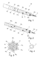
- the microprobe 50 shown on the Figure 1 comprises a plurality of seven microcables 40 1 , 40 2 , 40 3 , 40 4 , 40 5 , 40 6 , 40 7 assembled according to a strand shown more specifically to FIG. Figure 2 , each microcable constituting for the microprobe 50 a conduction line connected to a pole of the generator.
- a microcable comprises a core cable 11 surrounded by an insulation layer 20 so as to electrically isolate the microcables from each other.
- each core cable 11 is formed by a strand of seven elementary strands 10 whose diameter is, for example, 0.033 mm. The diameter of a core cable 11 is then 0.1 mm.
- elementary strands 10 of the type shown in FIG. Figure 4 that is to say comprising a core 1 made of a structuring material such as a stainless steel, a cobalt alloy of the MP35N series, a precious metal, titanium or a NiTi alloy, of high resistance to fatigue, the diameter of 0.033 mm allowing on average to guarantee a breaking strength in maximum fatigue in the extreme conditions of stress to which such structures can be subjected.
- a structuring material such as a stainless steel, a cobalt alloy of the MP35N series, a precious metal, titanium or a NiTi alloy
- radiopaque material 2 In order to guarantee sufficient X-ray visibility for the implantation of the microprobe, it may be necessary to introduce a minimum quantity of radiopaque material 2 along the core cable according to a composite structure that reconciles the fatigue resistance of the cable. and radiopacity, most materials used for their X-ray visibility, namely tantalum (Ta), tungsten (W), iridium (Ir), platinum (Pt) and gold (Au) generally not having a high resistance to fatigue.
- the microprobe has a risk of heating related to currents induced by "skin effect" outside the elementary strands under the action of the applied magnetic field.
- the small diameter given to the strands is favorable to heat dissipation and reduces the heating effects due to MRI.
- the thermal energy stored by the materials already limited in volume, can be further reduced if the unitary strands are coated with an outer layer of low magnetic susceptibility material (the magnetic susceptibility being the faculty of a material to to be magnetized under the action of an external magnetic field).
- the most favorable materials in this application are those whose magnetic susceptibility is less than 2000.10 -12 .m 3 .mole -1 , especially tantalum (Ta), titanium (Ti), rhodium (Rh), molybdenum ( Mo), tungsten (W), palladium (Pd) and gold (Au).
- the thickness of the isolation layer is 0.025 mm (25 ⁇ m). Microcables of 0.150 mm in diameter and a strand of seven microcables with a diameter of 0.45 mm are thus produced.
- the processes for producing the insulation layer 20 on the core cable are, for example, the coextrusion on the conductor or the heating of a heat-shrinkable tube.
- the insulation layers surrounding the core cables 11 of the microcables have at least one stripped area 30 intended to form, according to production methods which will be described in detail below, a detection / stimulation electrode for the microprobe 50, like the electrodes 52 of the Figure 1 .
- the stripped areas 30 are obtained in particular by the laser ablation technique.
- This example takes into account only one electrode at the distal end of the central microcable 40 7 .
- the number of electrodes there is no limitation to the number of electrodes, but for a microprobe consisting of seven stranded microcables, the number of poles is dependent on the number of microcables, here seven poles.
- Another possibility is to electrically connect a plurality of microcables to the same electrical potential, to increase the reliability by this redundancy.
- Figure 3 connect two (or three) of the seven microcables to the same pole of the generator proximal side, and distal side to group the electrodes of these microcables in the same stimulation area to form a specific point of stimulation - or, conversely , to remove them between them several centimeters to create a large area of stimulation.
- FIG. 1 shows more particularly that the microprobe 50 is surrounded by an outer sheath 51, except at the locations occupied by the electrodes 52.
- This sheath 51 may be heat-shrinkable polymer, such as polyethylene terephthalate (PET). Its thickness is typically 0.025 mm (25 ⁇ m), which corresponds to a final diameter of 0.5 mm or 1.5 French for the microprobe 50.
- PET polyethylene terephthalate
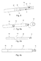
- the Figure 5 illustrates a first embodiment of the microprobe 50 in which conducting rings 52 platinum / iridium 90/10 type respectively placed opposite a stripped area 30 (not visible in the figure). Each ring 52 is fixed by reducing its outer diameter, for example by crimping, until the local contacting of the inner diameter of the ring 52 with the core cable 11 of the stripped microcable.
- the reduction of the diameter of the ring 52, obtained by deformation of material, causes intrinsic constraints on the ring but also on the insulation layers 20 and the core cables 11.
- the material of the rings 52 must therefore be sufficiently malleable so as not to damage the non-bare areas.
- the assembly of the microprobe 50 of the Figure 5 consists in alternately threading a length of heat-shrinkable sheath 51 and a conductive ring 52.
- the electrodes 52 are of the annular type and allow 360 ° stimulation.
- a first ring 53 referred to as an inner ring, also made of iridescent platinum, whose inner diameter is at least equal to the outer diameter of the microcables, ie 0.15 mm, for an outer diameter of 0.18 mm, is threaded on the one of the microcables 40 ( Figure 6a ) to be next to a bare area 30 ( Figure 6b ) and be set ( Figure 6c ) so as to make the electrical contact with the core cable 11 and keep the isodiameter.
- the outer diameter of the inner ring 53 is then 0.15 mm.
- This ring 53 is then used as visible mark ( Figure 7a ), under binocular in a vertical position, to allow the placement ( Figure 7b ) a second ring 52, said outer ring or stimulation, attached to the inner ring 53.
- a hole 521 is formed in the outer ring 52 ( Figure 7c ) to facilitate the orientation and positioning of the rings 52, 53 for a laser welding assembly.
- a particular microcable 40 has a zone 30 free of isolation layer 20 ( Figure 8a ). This stripped zone is covered by a deposit 31 of conductive glue ( Figure 8b ) allowing the mounting and positioning of an outer ring 52 which becomes the stimulation electrode in contact with the tissue ( Figure 8c ).
- the function of the conductive adhesive is to transmit an electric current between the two conductive components and to preserve the integrity of the insulation layers of the adjacent microcables. There is no risk of melting the polymer insulation layers, or to cut or reduce their thickness locally.
- This bonding technique can also be applied to the assembly of an inner ring 53 and an outer ring 52, as described with regard to Figures 7a to 7c .
- the structure located under the glued rings consists of rigid and non-compressible metal strands and insulating layers of flexible and therefore compressible polymer.
- This structure On a microscopic scale, it is possible to define this structure as flexible and can vary in size and in geometry.
- the use of glue makes it possible to compensate for these microscopic deformations by virtue of the intrinsic characteristics of the glue and to introduce a relative flexibility in the assembly of the two rings and to make this attachment less brittle when it is subjected to tensile stresses, bending or twisting.
- the Figure 9 shows a distal electrode 52 disposed at the end of the central microcable 40 7 and made according to one of the preceding embodiments, in particular that involving an inner ring and an outer ring.
- the strength of the structure is provided by an alternation of sheath elements 51 enveloping the strand of the seven microcables.
- the length in this alternation of the outer sheath is greater than the lengths of the gaps.
- This sheath also plays an important role in the manipulation of the microprobe during insertion into the catheter. It also ensures that the distal part is shaped to reduce the risk of moving the microprobe into the veins.
- each stimulation point is oriented angularly and does not allow annular stimulation.
- the surface of an electrode is about 0.314 mm 2 for a length of 1 mm. This low stimulation surface is favorable to the longevity of the battery.
- the Figures 11a and 11b represent a low-consumption dipole, consisting of spiral microcables and each covered, in this case, a heat-shrunk PET sheath.
- a stripped zone 30 of a length corresponding to a turn (360 °) is first produced, which makes it possible to increase the conducting surface of each core cable 11 to an equivalent value. to an annular ring type electrode.
- the conductive surface thus twisted offers a better contact with the tissues of the vein over 360 °.
- This architecture makes it possible to make a microprobe that can be used as a dipole and thus obtain a very small distance between the poles.
- the distance between poles is 0.15 mm, separated by a central microcable 40 7 of constant thickness.
- the position of the two stripped microcables at the periphery may be different in particular by alternating non-consecutive microcables such as sheathed microcable / stripped microcable.
- the advantage of such a device is to create an electric field between two electrodes at a very short distance, of identical surface, of the same material, and being in the same electrolyte, which has the consequence of increasing the intensity of the electric field.
Abstract
Description
L'invention concerne de façon générale les "dispositifs médicaux implantables actifs" tels que définis par la Directive 90/385/CEE du 20 juin 1990 du Conseil des communautés européennes.The invention relates generally to "active implantable medical devices" as defined by Council Directive 90/385 / EEC of 20 June 1990.
Cette définition inclut en particulier les implants cardiaques chargés de surveiller l'activité cardiaque et de générer des impulsions de stimulation, de défibrillation et/ou de resynchronisation en cas de trouble du rythme détecté par l'appareil, et/ou de détecter une activité électrique. Elle inclut aussi les appareils neurologiques, les implants cochléaires, les pompes de diffusion de substances médicales, les capteurs biologiques implantés, etc.This definition includes in particular cardiac implants responsible for monitoring cardiac activity and generating pacing, defibrillation and / or resynchronization pulses in case of arrhythmia detected by the apparatus, and / or for detecting electrical activity. . It also includes neurological devices, cochlear implants, diffusion pumps for medical substances, implanted biological sensors, etc.
Ces dispositifs comportent un boitier généralement désigné "générateur", raccordé électriquement et mécaniquement à une ou plusieurs "sondes" intracorporelles munie(s) d'électrodes destinées à venir en contact avec les tissus sur lesquels on souhaite appliquer des impulsions de stimulation et/ou recueillir un signal électrique : myocarde, nerf, muscle...These devices comprise a housing generally designated "generator", electrically and mechanically connected to one or more intracorporeal "probes" provided with (s) electrodes intended to come into contact with the tissues on which it is desired to apply stimulation pulses and / or collect an electrical signal: myocardium, nerve, muscle ...
La présente invention concerne plus précisément une microsonde de détection/stimulation destinée à être implantée dans des réseaux veineux, artériels ou lymphatiques.The present invention more specifically relates to a microprobe of detection / stimulation intended to be implanted in venous, arterial or lymphatic networks.
Le principe actuel de stimulation électrique des tissus est basé sur un dispositif, appelé généralement "sonde", qui est un objet implanté au travers de divers vaisseaux, veineux, artériels ou lymphatiques notamment, et dont la fonction est de transmettre un signal électrique au tissu-cible tout en garantissant les propriétés suivantes :
- facilité d'implantation par le médecin dans un réseau de vaisseaux du patient, et en particulier facilité : à faire progresser la sonde dans les vaisseaux par poussée, à faire suivre à la sonde des trajets tortueux et passer des embranchements, et à transmettre des couples ;
- visibilité aux rayons X afin de permettre au médecin une navigation aisée à travers les vaisseaux du réseau sous radioscopie X ;
- atraumaticité de la sonde au niveau des veines, ce qui nécessite une grande souplesse de structure et l'absence de transition rigide ou d'angle vif ;
- aptitude à transmettre un signal électrique aux tissus et à faire des mesures électriques monopolaires ou multipolaires de manière stable ;
- biocompatibilité avec les tissus vivants pour une implantation à long terme ;
- capacité à se connecter à un appareil implantable source de transmission du signal ;
- aptitude à la stérilisation (rayons gamma, température...) sans subir de dommages ;
- biostabilité, en particulier résistance à la corrosion dans le milieu vivant et résistance à la sollicitation mécanique en fatigue liée aux mouvements du patient et des organes ; et
- compatibilité avec l'imagerie IRM, particulièrement importante en neurologie.
- ease of implantation by the physician in a network of vessels of the patient, and in particular facilitated: to advance the probe in the vessels by pushing, to follow the probe tortuous paths and pass branch lines, and to transmit couples ;
- X-ray visibility to allow the physician easy navigation through the X-ray network vessels;
- atraumaticity of the probe at the level of the veins, which requires a great flexibility of structure and the absence of rigid transition or sharp angle;
- ability to transmit an electrical signal to tissues and to make monopolar or multipolar electrical measurements in a stable manner;
- biocompatibility with living tissue for long-term implantation;
- ability to connect to an implantable device that is a source of signal transmission;
- ability to sterilize (gamma rays, temperature ...) without being damaged;
- biostability, in particular resistance to corrosion in the living medium and resistance to mechanical stress in fatigue related to the movements of the patient and organs; and
- compatibility with MRI imaging, particularly important in neurology.
L'architecture actuelle des sondes répondant à ces besoins peut se résumer à une structure généralement creuse pour permettre le passage d'un mandrin ou d'un fil-guide, et comprenant des composants de type câbles conducteurs isolés, reliés à des électrodes mécaniques pour assurer la conductivité électrique, la radio-opacité, etc.The current architecture of the probes meeting these needs can be summarized as a generally hollow structure to allow the passage of a mandrel or a guide wire, and comprising insulated conductor cable components connected to mechanical electrodes for ensure electrical conductivity, radiopacity, etc.
Il s'agit donc de sondes nécessitant un assemblage complexe d'un nombre important de pièces, de fils et d'isolants associés, créant des risques non négligeables de rupture compte tenu des contraintes mécaniques à long terme auxquelles elles sont exposées.It is therefore probes requiring a complex assembly of a large number of parts, son and associated insulators, creating significant risk of rupture given the long-term mechanical stresses to which they are exposed.
Des exemples de telles sondes sont donnés dans les
Parmi les difficultés rencontrées, on peut citer la gestion des gradients de raideur liés aux pièces mécaniques utilisées, qui affectent fortement les propriétés d'implantabilité et de résistance mécanique sur le long terme (fatigue). De plus, en termes de fatigue des assemblages, toute zone de transition de rigidité est susceptible d'induire des risques de fatigue, des difficultés à stériliser du fait de la présence de zones d'accès difficile, et des problèmes de tenue des jonctions de conducteurs au niveau de la liaison avec les électrodes et le connecteur.Among the difficulties encountered, mention may be made of the management of stiffness gradients related to the mechanical parts used, which strongly affect the implantability and mechanical resistance properties over the long term (fatigue). Moreover, in terms of assembly fatigue, any stiffness transition zone is likely to induce risks of fatigue, difficulties to sterilize due to the presence of areas of difficult access, and problems with the holding of connection junctions. conductors at the connection with the electrodes and the connector.
Par ailleurs, la tendance clinique dans le domaine des sondes implantables est d'en réduire la taille afin de les rendre moins invasives et plus faciles à manipuler à travers les vaisseaux. La taille actuelle des sondes implantables est typiquement de l'ordre de 4 à 6 French (1,33 à 2 mm).In addition, the clinical trend in the field of implantable probes is to reduce their size to make them less invasive and easier to handle through the vessels. The current size of the implantable probes is typically in the range of 4 to 6 French (1.33 to 2 mm).
Cependant, il est clair que la réduction de la taille des sondes augmenterait leur complexité et imposerait des contraintes techniques génératrices de risques.However, it is clear that reducing the size of the probes would increase their complexity and impose technical constraints that generate risks.
Pourtant, une telle réduction, à moins de 1,5 French (0,5 mm) par exemple, ouvrirait des perspectives d'applications médicales dans des domaines variés allant de la cardiologie à la neurologie en présence d'un réseau veineux, artériel ou même lymphatique, comme le réseau veineux cérébral ou le réseau veineux du sinus coronaire.However, such a reduction, to less than 1.5 French (0.5 mm) for example, would open perspectives of medical applications in various fields ranging from cardiology to neurology in the presence of a venous, arterial or even the lymphatic system, such as the cerebral venous network or the venous network of the coronary sinus.
Aujourd'hui, la technologie de stimulation électrique a permis des avancées importantes dans le domaine de la neuromodulation, qui consiste à stimuler des zones-cibles du cerveau pour le traitement de la maladie de Parkinson, l'épilepsie et autres maladies neurologiques.Today, electrical stimulation technology has led to significant advances in the field of neuromodulation, which involves stimulating target areas of the brain for the treatment of Parkinson's disease, epilepsy and other neurological diseases.
On pourrait donc imaginer parvenir avec ce type de technologie à traiter de nouvelles régions difficilement atteignables aujourd'hui, ceci au moyen de sondes de stimulation de petite taille, ou "microsondes", présentant une grande robustesse afin de garantir la biostabilité à long terme. Avec des microsondes de taille réduite, il est possible d'envisager notamment le passage d'anastomoses pour établir par exemple un dispositif de stimulation du ventricule gauche via deux zones distinctes.One could thus imagine with this type of technology to treat new regions difficult to reach today, this by means of small stimulation probes, or "microworlds", with a great robustness in order to guarantee the long-term biostability. With microsondes of reduced size, it is possible to consider in particular the passage of anastomoses to establish for example a device for stimulating the left ventricle via two distinct areas.
Une telle technique permettrait également une approche moins invasive de ces traitements et surtout une efficacité supérieure des traitements administrés.Such a technique would also allow a less invasive approach to these treatments and above all a superior efficacy of the treatments administered.
Il serait en outre possible de connecter une ou plusieurs microsondes à travers le réseau de vaisseaux considéré jusqu'à leur localisation-cible. Leur mise en place pourrait être effectuée, du fait de leur taille réduite, par des dispositifs de guidage utilisés aujourd'hui en neuroradiologie interventionnelle pour la libération de ressorts (coils) lors du traitement des anévrismes intracrâniens. En particulier, des microsondes de 1,5 French seraient compatibles avec des cathéters de diamètre interne 1,6 French. D'autre part, il existe un besoin de pouvoir disposer de sondes multipolaires dans des applications liées à la fonction de "repositionnement électronique", laquelle offre de nombreuses possibilités de stimulation des tissus à travers le choix et la polarisation de certaines lignes de conduction parmi plusieurs incluses dans la microsonde. Cette technique permet de programmer des zones de stimulation en fonction de la thérapie, propriété très intéressante en particulier en neurologie.It would also be possible to connect one or more microwaves across the relevant vessel network to their target location. Their implementation could be carried out, because of their reduced size, by guiding devices used today in interventional neuroradiology for the release of springs ( coils ) during the treatment of intracranial aneurysms. In particular, microworlds of 1.5 French would be compatible with 1.6 French inner diameter catheters. On the other hand, there is a need to be able to have multipole probes in applications related to the function of "electronic repositioning", which offers many opportunities for tissue stimulation through the choice and polarization of certain conduction lines among several included in the microprobe. This technique allows to program zones of stimulation according to the therapy, very interesting property in particular in neurology.
Le
Le but de la présente invention est de proposer une microsonde de petite taille qui serait en conformité avec les propriétés générales des sondes implantables telles qu'elles ont été énumérées plus haut, tout en en réduisant la complexité et, de ce fait, le cout final, et en permettant par ailleurs de réaliser une connexion multipolaire sur un même microcâble afin de pouvoir polariser des lignes indépendamment les unes des autres et stimuler les tissus au moyen d'électrodes disposées en différentes positions le long de la microsonde.The object of the present invention is to provide a small microprobe that would be in accordance with the general properties of the implantable probes as listed above, while reducing the complexity and, therefore, the final cost. , and also allowing a multipolar connection to be made on the same microcable in order to be able to polarize lines independently of one another and to stimulate the tissues by means of electrodes arranged in different positions along the microprobe.
La taille de cette microsonde devrait notamment permettre d'atteindre des veinules de très petites dimensions, inaccessibles aujourd'hui avec des dispositifs de taille supérieure. La microsonde de l'invention devrait également faciliter sensiblement la navigabilité dans les réseaux veineux, artériels ou lymphatiques du fait de sa souplesse, amplifiée par ses petites dimensions.The size of this microprobe should in particular make it possible to reach venules of very small dimensions, inaccessible today with devices of greater size. The microprobe of the invention should also facilitate substantially navigability in the venous, arterial or lymphatic networks because of its flexibility, amplified by its small size.
De même, la microsonde de l'invention doit pouvoir répondre à un certains nombre d'exigences.Similarly, the microprobe of the invention must be able to meet a number of requirements.
Au niveau de la fiabilité de la liaison mécanique et électrique conducteur/électrode, il s'agit d'éviter les conceptions risquant d'altérer la tenue mécanique immédiate du conducteur par des assemblages de composants de continuité électrique insérés entre différentes portions de conducteurs. Il est préférable en ce sens de privilégier la continuité physique du conducteur. Il convient également d'assurer une étanchéité maximum afin de ne pas exposer les conducteurs aux fluides corporels.At the level of the reliability of the mechanical and electrical connection conductor / electrode, it is to avoid designs that could alter the immediate mechanical strength of the conductor by assembling electrical continuity components inserted between different portions of conductors. It is preferable in this sense to privilege physical continuity of the driver. It is also necessary to ensure a maximum seal in order not to expose the conductors to body fluids.
Au niveau des performances, il s'agit de :
- donner à la microsonde un diamètre extérieur compatible avec la taille des vaisseaux visés ;
- ne pas altérer localement la grande flexibilité de la microsonde afin de conserver une maniabilité maximale, notamment au passage à travers les petites veines ;
- assurer un profil isodiamétrique pour permettre le passage dans un cathéter implantable et les veines ; et
- faciliter et simplifier la procédure d'assemblage microsonde/cathéter. Conformément à l'invention, ce but est atteint grâce à une microsonde multipolaire de détection/stimulation destinée à être implantée dans des réseaux veineux, artériels ou lymphatiques.
- to give the microprobe an outer diameter compatible with the size of the target ships;
- do not locally alter the flexibility of the microprobe to maintain maximum maneuverability, especially when passing through small veins;
- provide an isodiametric profile to allow passage into an implantable catheter and veins; and
- facilitate and simplify the microprobe / catheter assembly procedure. According to the invention, this object is achieved by means of a multipolar detection / stimulation microprobe designed to be implanted in venous, arterial or lymphatic networks.
Comme divulgué par le
La sonde de l'invention est remarquable en ce que les torons de brins des différents microcâbles sont eux-mêmes assemblés ensemble en un toron de microcâbles, ce toron de microcâbles formant une partie active distale de stimulation multipolaire de la sonde, et en ce que la sonde est une microsonde, le diamètre de la partie active distale étant au plus égal à 1,5 French (0,5 mm).The probe of the invention is remarkable in that the strand strands of the various microcables are themselves assembled together in a microcable strand, this microcable strand forming a distal active portion of multipolar stimulation of the probe, and in that the probe is a microprobe, the diameter of the distal active part being at most 1.5 French (0.5 mm).
Ainsi, on comprend qu'avec un diamètre ne dépassant pas 0,5 mm, la microsonde selon l'invention présente une grande flexibilité, favorable à sa manipulation par le médecin, notamment au cours de son implantation lorsqu'il s'agit par exemple de l'introduire dans des réseaux de vaisseaux avec de fortes tortuosités et de nombreux embranchements et d'éviter des traumatismes que pourraient engendrer des sondes beaucoup plus rigides, incompatibles avec les tissus.Thus, it is understood that with a diameter not exceeding 0.5 mm, the microprobe according to the invention has great flexibility, favorable to its handling by the doctor, especially during its implantation when it comes for example to introduce it into networks of vessels with strong tortuosities and many branches and to avoid trauma that could lead to much more rigid probes, incompatible with the tissues.
Selon un mode de réalisation de l'invention, le câble de coeur est formé par une pluralité de brins élémentaires de 0,033 mm de diamètre. En particulier, un câble de coeur de 0,1 mm est formé par un toron de sept brins élémentaires de 0,033 mm de diamètre.According to one embodiment of the invention, the core cable is formed by a plurality of elementary strands of 0.033 mm in diameter. In particular, a core cable of 0.1 mm is formed by a strand of seven elementary strands of 0.033 mm in diameter.
Le choix d'une structure multifilaire toronnée composée de brins élémentaires très fins pour réaliser les câbles de coeur permet d'augmenter leur résistance à la fatigue mécanique due aux mouvements du patient et des organes, sachant que la limite de rupture en flexion d'un fil est sensiblement inversement proportionnelle à son diamètre.The choice of a stranded multifilament structure composed of very thin elementary strands for making the core cables makes it possible to increase their resistance to mechanical fatigue due to the movements of the patient and the organs, knowing that the flexural rupture limit of a wire is substantially inversely proportional to its diameter.
De manière à renforcer cette importante propriété de biostabilité, il y a avantage à ce que les brins élémentaires présentent une structure composite constituée d'un matériau structurant et d'un matériau radio-opaque. De préférence, le matériau structurant a une résistance à la fatigue intrinsèque élevée, comme par exemple un acier inox, un alliage de cobalt MP35N, un métal précieux, le titane ou un alliage NiTi connu notamment sous le nom de nitinol. À ces métaux chargés d'assurer les qualités mécaniques du câble de coeur s'ajoute un matériau radio-opaque destiné à rendre la microsonde visible aux rayons X lors de sa mise en place par le médecin. Le matériau radio-opaque peut être choisi parmi le tantale (Ta), le tungstène (W), l'iridium (Ir), le platine (Pt) et l'or (Au).In order to reinforce this important property of biostability, it is advantageous for the elementary strands to have a composite structure consisting of a structuring material and a radiopaque material. Preferably, the structuring material has a high intrinsic fatigue resistance, such as for example a stainless steel, a cobalt alloy MP35N, a precious metal, titanium or a NiTi alloy known in particular under the name of nitinol. To these metals responsible for ensuring the mechanical properties of the heart cable is added a radiopaque material intended to make the microprobe visible to X-rays when it is put in place by the doctor. The radiopaque material may be selected from tantalum (Ta), tungsten (W), iridium (Ir), platinum (Pt) and gold (Au).
Pour réaliser le contact électrique avec les tissus et transmettre les signaux électriques de détection/stimulation, l'invention propose une solution qui consiste à utiliser les câbles de coeur pour former les électrodes de la microsonde en ménageant des zones dénudées dans une couche d'isolement entourant les câbles.In order to make electrical contact with the tissues and to transmit the electrical detection / stimulation signals, the invention proposes a solution that consists in using the core cables to form the electrodes of the microprobe by providing bare areas in an isolation layer. surrounding the cables.
De préférence, la couche d'isolement est en polymère fluoré, éthylène tétrafluoroéthylène (ETFE) par exemple, et a une épaisseur de 25 µm.Preferably, the insulation layer is made of fluorinated polymer, ethylene tetrafluoroethylene (ETFE) for example, and has a thickness of 25 microns.
Selon un mode de réalisation avantageux, la microsonde selon l'invention est constituée d'un toron de microcâbles, en particulier de sept microcâbles. L'invention prévoit également qu'une gaine en polymère thermorétractable, en polyester (PET) par exemple, entoure partiellement la microsonde.According to an advantageous embodiment, the microprobe according to the invention consists of a strand of microcables, in particular of seven microcables. The invention also provides that a sheath of heat-shrinkable polymer, polyester (PET) for example, partially surrounds the microprobe.
Afin de limiter l'échauffement du câble de coeur par effet de peau lors d'une imagerie par IRM, l'invention recommande que les brins comprennent une couche extérieure en matériau à faible susceptibilité magnétique, inférieure à 2000.10-12.m3.mole-1. Le matériau à faible susceptibilité magnétique peut être, au choix, le tantale (Ta), le titane (Ti), le rhodium (Rh), le molybdène (Mo), le tungstène (W), le palladium (Pd) et l'or (Au). Selon une première variante de réalisation de la microsonde selon l'invention, une électrode de détection/stimulation comprend une bague conductrice fixée sur une zone dénudée de microcâble par réduction de son diamètre extérieur.In order to limit the heating of the core rope by skin effect in an MRI imaging, the invention recommends that the strands comprise an outer layer of low magnetic susceptibility material, less than 2000.10 -12 .m 3 .mole -1 . The material with low magnetic susceptibility can be, alternatively, tantalum (Ta), titanium (Ti), rhodium (Rh), molybdenum (Mo), tungsten (W), palladium (Pd) and gold (Au). According to a first embodiment of the microprobe according to the invention, a detection / stimulation electrode comprises a conductive ring fixed on a stripped zone of microcable by reducing its outer diameter.
Afin d'éviter les contraintes sur la bague, les gaines et les torons, l'invention prévoit une seconde variante selon laquelle une électrode de détection/stimulation comprend, d'une part, une bague conductrice intérieure fixée sur une zone dénudée par réduction de son diamètre extérieur, et, d'autre part, une bague conductrice extérieure fixée sur la bague intérieure. Les bagues conductrices sont par exemple en platine iridié. Avantageusement, la bague extérieure est fixée sur la bague intérieure par soudure laser ou par collage au moyen d'une colle conductrice. L'invention prévoit également qu'une électrode de détection/stimulation comprend une bague conductrice fixée sur une zone dénudée par collage au moyen d'une colle conductrice.In order to avoid stresses on the ring, the sheaths and the strands, the invention provides a second variant according to which a detection / stimulation electrode comprises, on the one hand, an inner conductive ring fixed on a denuded zone by reduction of its outer diameter, and on the other hand, an outer conductive ring fixed on the inner ring. The conductive rings are for example platinum iridium. Advantageously, the outer ring is fixed to the inner ring by laser welding or by gluing by means of a conductive glue. The invention also provides that a detection / stimulation electrode comprises a conductive ring fixed on a stripped area by gluing by means of a conductive glue.
Selon une autre variante, la zone dénudée s'étend sur 360°, sur une longueur correspondant à une spire de toron de microcâbles. Il est alors possible de réaliser sur la microsonde au moins un dipôle constitué de deux zones dénudées sur 360° disposées en regard sur deux microcâbles non consécutifs.According to another variant, the stripped zone extends over 360 °, over a length corresponding to a turn of strand of microcables. It is then possible to perform on the microprobe at least one dipole consisting of two denuded zones 360 ° arranged facing two non-consecutive microcables.
Enfin, il est avantageux que les extrémités distales des microcâbles soient décalées longitudinalement les unes par rapport aux autres, de manière à produire une diminution progressive du diamètre et introduire un gradient de raideur dans la partie la plus distale de la microsonde.Finally, it is advantageous for the distal ends of the microcables to be offset longitudinally relative to each other so as to produce a gradual decrease in the diameter and to introduce a stiffness gradient in the most distal part of the microprobe.
On va maintenant décrire des exemples de mise en oeuvre de l'invention, en référence aux dessins annexés où les mêmes références numériques désignent d'une figure à l'autre des éléments identiques ou fonctionnellement semblables.
- La
Figure 1 est une vue partielle en perspective d'une microsonde multipolaire de détection/stimulation conforme à l'invention. - La
Figure 2 représente la microsonde de laFigure 1 avant mise en place de la gaine extérieure et des électrodes. - La
Figure 3 est une section droite de la vue de laFigure 2 . - La
figure 4 est une vue en coupe d'un brin élémentaire d'un microcâble montré à laFigure 3 . - La
Figure 5 est une vue partielle en perspective d'une microsonde réalisée selon une première variante de réalisation de l'invention. - Les
Figures 6a à 6c sont des vues illustrant les étapes de mise en place d'une bague intérieure sur un microcâble conformément à une deuxième variante de réalisation. - Les
Figures 7a à 7c sont des vues illustrant les étapes de fixation par soudure laser d'une bague extérieure sur la bague intérieure desFigures 6a à 6b . - Les
Figures 8a à 8c sont des vues illustrant les étapes de fixation par collage d'une bague extérieure sur une zone dénudée d'un microcâble. - La
Figure 9 est une vue partielle en perspective montrant une électrode en partie distale du microcâble central de la microsonde de laFigure 1 . - La
Figure 10 est une vue partielle en perspective d'une microsonde réalisée selon une troisième variante de réalisation. - Les
Figures 11a et 11b sont des vues montrant la réalisation d'un dipôle sur une microsonde conforme à l'invention. - Les
Figures 12a et 12b illustrent un perfectionnement des modes de réalisation décrits aux Figures précédentes, permettant d'obtenir une réduction progressive du diamètre en extrémité distale de la sonde.
- The
Figure 1 is a partial perspective view of a multipolar microprobe of detection / stimulation according to the invention. - The
Figure 2 represents the microprobe of theFigure 1 before placing the outer sheath and the electrodes. - The
Figure 3 is a cross section of the view of theFigure 2 . - The
figure 4 is a sectional view of an elementary strand of a microcable shown inFigure 3 . - The
Figure 5 is a partial perspective view of a microprobe made according to a first embodiment of the invention. - The
Figures 6a to 6c are views illustrating the steps of setting up an inner ring on a microcable according to a second embodiment. - The
Figures 7a to 7c are views illustrating the steps of laser welding attachment of an outer ring to the inner ring ofFigures 6a to 6b . - The
Figures 8a to 8c are views illustrating the steps of adhesive bonding an outer ring to a bare area of a microcable. - The
Figure 9 is a partial perspective view showing an electrode partly distal of the central microcable of the microprobe of theFigure 1 . - The
Figure 10 is a partial perspective view of a microprobe made according to a third embodiment. - The
Figures 11a and 11b are views showing the realization of a dipole on a microprobe according to the invention. - The
Figures 12a and 12b illustrate an improvement of the embodiments described in the preceding figures, making it possible to obtain a progressive reduction of the diameter at the distal end of the probe.
Les microsondes concernées par l'invention sont des microsondes multipolaires de détection/stimulation destinées à être implantées dans des réseaux veineux, artériels ou lymphatiques, et dont le diamètre ne dépasse pas 1,5 French (0,5 mm). Elles sont plus particulièrement adaptées aux applications mettant en oeuvre la fonction de repositionnement électronique, évoquée plus haut, qui implique une pluralité de lignes de conduction isolées et indépendantes, chacune reliée à un pôle du générateur d'un dispositif implantable via un connecteur de type IS-1 ou IS-4 pour une sonde cardiaque, ou même un plus grand nombre de pôles plus pour une sonde neurologique.The microworlds concerned by the invention are multipolar detection / stimulation microprobes intended to be implanted in venous, arterial or lymphatic networks, and whose diameter does not exceed 1.5 French (0.5 mm). They are more particularly adapted to applications implementing the electronic repositioning function, mentioned above, which involves a plurality of isolated and independent conduction lines, each connected to a pole of the generator of an implantable device via an IS-1 or IS-4 type connector for a heart probe, or even more poles for a neurological probe.
La microsonde 50 montrée sur la
Comme le montre la
Dans l'exemple de réalisation montré sur la section droite de la
Il est proposé par l'invention d'utiliser des brins élémentaires 10 du type de celui représenté sur la
Afin de garantir une visibilité aux rayons X suffisante pour l'implantation de la microsonde, il peut être nécessaire d'introduire le long du câble de coeur une quantité minimale de matériau radio-opaque 2 selon une structure composite conciliant résistance à la fatigue du câble et radio-opacité, la plupart des matériaux utilisés pour leur visibilité aux rayons X, à savoir le tantale (Ta), le tungstène (W), l'iridium (Ir), le platine (Pt) et l'or (Au) ne présentant pas en général une grande résistance à la fatigue.In order to guarantee sufficient X-ray visibility for the implantation of the microprobe, it may be necessary to introduce a minimum quantity of
On sait, d'une manière générale, que la compatibilité des dispositifs implantables avec les techniques médicales modernes d'imagerie, telles que l'IRM, est fondamentale pour garantir un traitement optimal du patient.It is generally known that the compatibility of implantable devices with modern medical imaging techniques, such as MRI, is fundamental to ensuring optimal patient treatment.
En effet, du fait de sa structure globalement métallique, la microsonde présente un risque d'échauffement lié aux courants induits par "effet de peau" à l'extérieur des brins élémentaires sous l'action du champ magnétique appliqué. Le faible diamètre donné aux brins est toutefois favorable à la dissipation thermique et réduit les effets d'échauffement dus à l'IRM. De plus, l'énergie thermique emmagasinée par les matériaux, déjà limitée en volume, peut encore être diminuée si les brins unitaires sont revêtus d'une couche extérieure en matériau à faible susceptibilité magnétique (la susceptibilité magnétique étant la faculté d'un matériau à s'aimanter sous l'action d'un champ magnétique extérieur).Indeed, because of its overall metallic structure, the microprobe has a risk of heating related to currents induced by "skin effect" outside the elementary strands under the action of the applied magnetic field. The small diameter given to the strands, however, is favorable to heat dissipation and reduces the heating effects due to MRI. In addition, the thermal energy stored by the materials, already limited in volume, can be further reduced if the unitary strands are coated with an outer layer of low magnetic susceptibility material (the magnetic susceptibility being the faculty of a material to to be magnetized under the action of an external magnetic field).
Les matériaux les plus favorables dans cette application sont ceux dont la susceptibilité magnétique est inférieure à 2000.10-12.m3.mole-1, notamment le tantale (Ta), le titane (Ti), le rhodium (Rh), le molybdène (Mo), le tungstène (W), le palladium (Pd) et l'or (Au).The most favorable materials in this application are those whose magnetic susceptibility is less than 2000.10 -12 .m 3 .mole -1 , especially tantalum (Ta), titanium (Ti), rhodium (Rh), molybdenum ( Mo), tungsten (W), palladium (Pd) and gold (Au).
De préférence, l'épaisseur de la couche 20 d'isolement est de 0,025 mm (25 µm). On réalise ainsi des microcâbles de 0,150 mm de diamètre et un toron de sept microcâbles de diamètre égal à 0,45 mm.Preferably, the thickness of the isolation layer is 0.025 mm (25 μm). Microcables of 0.150 mm in diameter and a strand of seven microcables with a diameter of 0.45 mm are thus produced.
Les caractéristiques requises pour la couche 20 d'isolement sont les suivantes :
- résistance à la fatigue,
- isolement électrique,
- biocompatibilité à long terme,
- biostabilité,
- possibilité de transformation et mise en oeuvre compatible avec le conducteur du câble de coeur.
- fatigue resistance,
- electrical isolation,
- long-term biocompatibility,
- biostability,
- possibility of transformation and implementation compatible with the conductor of the heart cable.
Pour réaliser la couche 20 d'isolement, on privilégiera les matériaux à forte inertie chimique comme les polymères fluorés, qui présentent également une très bonne qualité d'isolation. Parmi ces composés, on peut citer en particulier l'ETFE (éthylène tétrafluoroéthylène).To achieve the
Les procédés de réalisation de la couche 20 d'isolement sur le câble de coeur sont, par exemple, la co-extrusion sur le conducteur ou l'échauffement d'un tube thermorétractable.The processes for producing the
Comme on peut le voir sur les
Dans le cadre de stimulation dans une anastomose, par exemple, il est facilement envisageable d'ajouter une ou plusieurs séries d'électrodes sur chacun des microcâbles, ceci afin d'augmenter le nombre de points de stimulation :
- avec une électrode par microcâble périphérique, on obtient six électrodes périphériques et une à l'extrémité distale du microcâble central, soit sept pôles et sept électrodes ;
- avec deux électrodes par microcâble périphérique, on obtient douze électrodes périphériques et une à l'extrémité distale du microcâble central, soit sept pôles et treize électrodes ;
- avec trois électrodes par microcâble périphérique, on obtient dix-huit électrodes périphériques et une à l'extrémité distale du microcâble central, soit sept pôles et dix-neuf électrodes ;
- etc.
- with a peripheral microcable electrode, six peripheral electrodes are obtained and one at the distal end of the central microcable, ie seven poles and seven electrodes;
- with two electrodes per peripheral microcable, twelve peripheral electrodes are obtained and one at the distal end of the central microcable, ie seven poles and thirteen electrodes;
- with three electrodes per peripheral microcable, eighteen peripheral electrodes are obtained and one at the distal end of the central microcable, ie seven poles and nineteen electrodes;
- etc.
Cet exemple ne prend en compte qu'une seule électrode en extrémité distale du microcâble central 407. Il est cependant possible d'y placer une pluralité d'électrodes si le microcâble est allongé en partie distale. Dans ce cas, il n'y a pas de limitation au nombre d'électrodes, mais pour une microsonde constituée de sept microcâbles toronnés, le nombre de pôles est dépendant du nombre de microcâbles, soit ici sept pôles.This example takes into account only one electrode at the distal end of the
Une autre possibilité consiste à relier électriquement une pluralité de microcâbles à un même potentiel électrique, pour accroitre la fiabilité par cette redondance.Another possibility is to electrically connect a plurality of microcables to the same electrical potential, to increase the reliability by this redundancy.
On peut ainsi prévoir par exemple, avec une structure 7x7 telle que celle illustrée
Enfin, la
La
La réduction du diamètre de la bague 52, obtenue par déformation de matière, entraine des contraintes intrinsèques à la bague mais aussi sur les couches 20 d'isolement et les câbles 11 de coeur. La matière des bagues 52 doit donc être suffisamment malléable afin de ne pas endommager les zones non dénudées.The reduction of the diameter of the
L'assemblage de la microsonde 50 de la
Il est à noter que les électrodes 52 sont de type annulaire et permettent une stimulation sur 360°.It should be noted that the
L'ensemble des
Dans la variante des
Cette bague 53 est ensuite utilisée comme repère visible (
Cette solution évite de soumettre les sept microcâbles à un effort de sertissage. Le contact électrique est alors reporté entre les deux bagues 52, 53. Les risques de dommage par sertissage sur les couches 20 d'isolement des microcâbles sont ainsi réduits.This solution avoids subjecting the seven microcables to a crimping effort. The electrical contact is then transferred between the two
Un trou 521 est ménagé dans la bague extérieure 52 (
Selon la variante des
La colle conductrice a pour fonction de transmettre un courant électrique entre les deux composants conducteurs et de préserver l'intégrité des couches d'isolement des microcâbles adjacents. Il n'y a pas de risque de faire fondre le polymère des couches d'isolement, ni de les couper ou de réduire localement leur épaisseur.The function of the conductive adhesive is to transmit an electric current between the two conductive components and to preserve the integrity of the insulation layers of the adjacent microcables. There is no risk of melting the polymer insulation layers, or to cut or reduce their thickness locally.
Une large gamme de colles biocompatibles et couramment utilisées dans les appareils médicaux implantables est disponible auprès de la société Epoxy Technology, Inc., par exemple sous la référence EPO-TEK (marque déposée).A wide range of biocompatible glues and commonly used in implantable medical devices is available from Epoxy Technology, Inc., for example as EPO-TEK (Trade Mark).
Cette technique de collage peut s'appliquer également à l'assemblage d'une bague intérieure 53 et d'une bague extérieure 52, telles que décrites en regard des
La structure située sous les bagues collées est constituée de brins métalliques rigides et non compressibles et de couches isolantes en polymère souple et donc compressible. À une échelle microscopique, il est possible de définir cette structure comme souple et pouvant varier en dimension et en géométrie. L'usage de colle permet de compenser ces déformations microscopiques grâce aux caractéristiques intrinsèques de la colle et d'introduire une relative souplesse dans l'assemblage des deux bagues et de rendre cette fixation moins cassante lorsqu'elle est soumise à des contraintes de traction, flexion ou torsion.The structure located under the glued rings consists of rigid and non-compressible metal strands and insulating layers of flexible and therefore compressible polymer. On a microscopic scale, it is possible to define this structure as flexible and can vary in size and in geometry. The use of glue makes it possible to compensate for these microscopic deformations by virtue of the intrinsic characteristics of the glue and to introduce a relative flexibility in the assembly of the two rings and to make this attachment less brittle when it is subjected to tensile stresses, bending or twisting.
La
La
La tenue de la structure est assurée par une alternance d'éléments de gaine 51 enveloppant le toron des sept microcâbles. De préférence, la longueur dans cette alternance de la gaine extérieure est supérieure aux longueurs des intervalles. Cette gaine joue également un rôle important dans la manipulation de la microsonde, lors de l'insertion dans le cathéter. Elle assure également la mise en forme de la partie distale afin de réduire le risque de déplacement de la microsonde dans les veines.The strength of the structure is provided by an alternation of
Il est à noter que, dans cette configuration, chaque point de stimulation est orienté angulairement et ne permet pas une stimulation annulaire.It should be noted that in this configuration, each stimulation point is oriented angularly and does not allow annular stimulation.
La surface d'une électrode est d'environ 0,314 mm2 pour une longueur de 1 mm. Cette faible surface de stimulation est favorable à la longévité de la batterie.The surface of an electrode is about 0.314 mm 2 for a length of 1 mm. This low stimulation surface is favorable to the longevity of the battery.
Les
La surface conductrice ainsi torsadée offre un meilleur contact avec les tissus de la veine sur 360°.The conductive surface thus twisted offers a better contact with the tissues of the vein over 360 °.
Cette architecture permet de réaliser une microsonde qui pourra être utilisée comme dipôle et obtenir ainsi une distance très faible entre les pôles. Dans cet exemple la distance entre pôles est de 0,15 mm, séparée par un microcâble central 407 d'épaisseur constante.This architecture makes it possible to make a microprobe that can be used as a dipole and thus obtain a very small distance between the poles. In this example the distance between poles is 0.15 mm, separated by a
La position des deux microcâbles dénudés en périphérie peut être différente notamment par alternance de microcâbles non consécutifs tels que microcâble gainé/microcâble dénudé.The position of the two stripped microcables at the periphery may be different in particular by alternating non-consecutive microcables such as sheathed microcable / stripped microcable.
L'avantage d'un tel dispositif est de créer un champ électrique entre deux électrodes à très faible distance, de surface identique, de même matière, et se trouvant dans un même électrolyte, ce qui a pour conséquence d'augmenter l'intensité du champ électrique.The advantage of such a device is to create an electric field between two electrodes at a very short distance, of identical surface, of the same material, and being in the same electrolyte, which has the consequence of increasing the intensity of the electric field.
Les
Ce décalage longitudinal des extrémités des différents torons offre un double avantage :
- en premier lieu, il introduit dans la partie la plus distale de la microsonde un gradient de raideur évitant un changement brutal de diamètre entre le faisceau regroupant tous les microcâbles 401 à 407 et le seul microcâble central 407, ce qui réduit fortement les risques de rupture prématurée des composants sous l'effet de contraintes mécaniques de flexion ;
- par ailleurs, il améliore l'isolement électrique entre les torons, et donc l'isolement des différents pôles de la microsonde, en évitant toute proximité immédiate d'extrémités non isolées des coeurs conducteurs des différents microcâbles.
- firstly, it introduces into the most distal part of the microprobe a stiffness gradient avoiding a sudden change in diameter between the beam grouping all the
microcables 40 1 to 40 7 and the singlecentral microcable 40 7 , which greatly reduces the risks of premature failure of the components under the effect of mechanical bending stresses; - Moreover, it improves the electrical insulation between the strands, and thus the isolation of the different poles of the microprobe, avoiding any immediate proximity of uninsulated ends of the conductive cores of the various microcables.
Claims (20)
cette sonde comprenant une pluralité de microcâbles (401, 402, 403, 404, 405, 406, 407),
chaque microcâble comprenant un câble de coeur (11) électriquement conducteur, apte à être relié à un pôle d'un générateur multipolaire d'un dispositif médical implantable actif, et une couche d'isolement (20) en polymère entourant le câble de coeur et comprenant au moins une zone dénudée (30) ménagée dans la couche d'isolement et destinée à former une électrode (52) de détection/stimulation monopolaire,
chaque câble de coeur étant formé par une pluralité de brins élémentaires assemblés ensemble en un toron de brins respectif,
sonde caractérisée en ce que :
ce toron de microcâbles formant une partie active distale de détection/stimulation multipolaire de la sonde, et
this probe comprising a plurality of microcables (40 1 , 40 2 , 40 3 , 40 4 , 40 5 , 40 6 , 40 7 ),
each microcable comprising an electrically conductive core cable (11), connectable to a pole of a multipolar generator of an active implantable medical device, and an insulation layer (20) of polymer surrounding the core cable and comprising at least one stripped area (30) in the insulating layer for forming a monopolar detection / stimulation electrode (52),
each core cable being formed by a plurality of elementary strands assembled together into a respective strand strand,
probe characterized in that
this strand of microcables forming a distal active portion of detection / multipolar stimulation of the probe, and
de manière à produire une diminution progressive du diamètre et introduire un gradient de raideur dans la partie la plus distale de la microsonde.The probe of claim 1, wherein the distal ends of the microcables (40 1 , 40 2 , 40 3 , 40 4 , 40 5 , 40 6 , 40 7 ) are longitudinally offset (ℓ) from one another,
to produce a gradual decrease in diameter and introduce a stiffness gradient in the most distal part of the microprobe.
Applications Claiming Priority (1)
| Application Number | Priority Date | Filing Date | Title |
|---|---|---|---|
| FR1259758 | 2012-10-12 |
Publications (2)
| Publication Number | Publication Date |
|---|---|
| EP2719422A1 true EP2719422A1 (en) | 2014-04-16 |
| EP2719422B1 EP2719422B1 (en) | 2015-02-18 |
Family
ID=47428707
Family Applications (1)
| Application Number | Title | Priority Date | Filing Date |
|---|---|---|---|
| EP13169168.5A Active EP2719422B1 (en) | 2012-10-12 | 2013-05-24 | Implantable multipolar detection/stimulation microprobe |
Country Status (3)
| Country | Link |
|---|---|
| US (2) | US10463848B2 (en) |
| EP (1) | EP2719422B1 (en) |
| CN (1) | CN103721342B (en) |
Cited By (6)
| Publication number | Priority date | Publication date | Assignee | Title |
|---|---|---|---|---|
| EP2959828A1 (en) | 2014-06-25 | 2015-12-30 | Sorin CRM SAS | Hybrid assembly forming an active implantable medical device |
| EP3058983A1 (en) | 2015-02-17 | 2016-08-24 | Sorin CRM SAS | Detection/stimulation microprobe, in particular for multipoint neuromodulation of the central nervous system |
| EP3069755A1 (en) | 2015-03-18 | 2016-09-21 | Sorin CRM SAS | Active implantable medical device comprising a connector-free capsule, permanently connected to a microprobe |
| WO2017158174A1 (en) | 2016-03-18 | 2017-09-21 | Sorin Crm Sas | Active implantable medical device for combined treatment of cardiac rhythm and of respiratory rhythm |
| WO2017198472A1 (en) | 2016-05-19 | 2017-11-23 | Sorin Crm Sas | Dual multipolar lead implantable in the coronary venous network |
| EP3591763A1 (en) | 2018-07-06 | 2020-01-08 | Sorin CRM SAS | Connection method for connecting an insulated micro-conductor |
Families Citing this family (8)
| Publication number | Priority date | Publication date | Assignee | Title |
|---|---|---|---|---|
| EP2664354B1 (en) * | 2012-05-16 | 2015-09-16 | Sorin CRM SAS | Medical lead with a ring electrode for implantation in a cardiac or cerebral blood vessel and a method for its manufacture |
| US20130310673A1 (en) * | 2012-05-17 | 2013-11-21 | Assaf Govari | Guide wire with position sensing electrodes |
| WO2015117066A1 (en) * | 2014-02-03 | 2015-08-06 | Volcano Corporation | Intravascular devices,systems, and methods having a core wire with embedded conductors |
| US20170189674A1 (en) * | 2016-01-04 | 2017-07-06 | Medtronic, Inc. | Medical electrical lead |
| EP3542853B1 (en) * | 2018-03-23 | 2021-05-05 | Heraeus Deutschland GmbH & Co. KG | Manufacturing method for a microlead |
| EP3673951B1 (en) | 2018-12-28 | 2022-05-04 | Heraeus Medical Components, LLC | Overmolded segmented electrode |
| DE102019218477B4 (en) * | 2019-11-28 | 2022-01-05 | Heraeus Deutschland GmbH & Co. KG | Micro-lead for directional stimulation |
| KR102463096B1 (en) * | 2021-01-19 | 2022-11-03 | 주식회사 페라자 | Multiple Helix Flexible Mechanism |
Citations (4)
| Publication number | Priority date | Publication date | Assignee | Title |
|---|---|---|---|---|
| US6192280B1 (en) | 1999-06-02 | 2001-02-20 | Medtronic, Inc. | Guidewire placed implantable lead with tip seal |
| US7047082B1 (en) | 1999-09-16 | 2006-05-16 | Micronet Medical, Inc. | Neurostimulating lead |
| EP2384784A1 (en) * | 2010-05-05 | 2011-11-09 | Sorin CRM SAS | Assembly for endocavitary stimulation/defibrillation of the left ventricle |
| EP2455131A1 (en) | 2010-11-19 | 2012-05-23 | Sorin CRM SAS | Probe for stimulating a left cavity of the heart which can be implanted in the coronary network |
Family Cites Families (25)
| Publication number | Priority date | Publication date | Assignee | Title |
|---|---|---|---|---|
| US1691869A (en) * | 1924-07-03 | 1928-11-13 | Frank F Fowle | Electrical conductor |
| US2320470A (en) * | 1938-04-11 | 1943-06-01 | Mackworth G Rees | Current delivering and conducting means |
| JPS60172755A (en) * | 1984-02-17 | 1985-09-06 | Honda Motor Co Ltd | Control device for speed change gear of vehicle |
| JPH066115B2 (en) * | 1987-08-27 | 1994-01-26 | 新技術事業団 | Electrodes for implantation in the body |
| EP0312495A3 (en) * | 1987-10-16 | 1989-08-30 | Institut Straumann Ag | Electrical cable for carrying out at least one stimulation and/or measurement in a human or animal body |
| US4945341A (en) | 1989-04-05 | 1990-07-31 | Buttimer Gregory J | Alarm system for electrical devices |
| US5246014A (en) * | 1991-11-08 | 1993-09-21 | Medtronic, Inc. | Implantable lead system |
| US5760341A (en) * | 1996-09-10 | 1998-06-02 | Medtronic, Inc. | Conductor cable for biomedical lead |
| US6324415B1 (en) * | 1997-07-30 | 2001-11-27 | Intermedics Inc. | Cardiac lead with minimized inside diameter of sleeve |
| US6216045B1 (en) * | 1999-04-26 | 2001-04-10 | Advanced Neuromodulation Systems, Inc. | Implantable lead and method of manufacture |
| US20030236562A1 (en) * | 2000-10-10 | 2003-12-25 | Kuzma Janusz A. | Band type multicontact electrode and method of making the same |
| US7138582B2 (en) * | 2003-06-24 | 2006-11-21 | Medtronic, Inc. | Medical electrical lead conductor formed from modified MP35N alloy |
| US7155294B2 (en) * | 2003-06-26 | 2006-12-26 | Medtronic, Inc. | Conductor arrangement for multipolar medical electrical leads |
| US7420124B2 (en) * | 2004-02-11 | 2008-09-02 | Fort Wayne Metals Research Products Corp. | Drawn strand filled tubing wire |
| WO2006058096A1 (en) * | 2004-11-23 | 2006-06-01 | Advanced Neuromodulation Systems, Incorporated | Method for producing a multielectrode lead |
| US20080046059A1 (en) * | 2006-08-04 | 2008-02-21 | Zarembo Paul E | Lead including a heat fused or formed lead body |
| US20080114230A1 (en) * | 2006-11-14 | 2008-05-15 | Bruce Addis | Electrode support |
| US8155756B2 (en) * | 2007-02-16 | 2012-04-10 | Pacesetter, Inc. | Motion-based optimization for placement of cardiac stimulation electrodes |
| WO2009035708A1 (en) * | 2007-09-13 | 2009-03-19 | Medtronic, Inc. | Medical electrical profiled lead |
| US20110220408A1 (en) * | 2009-02-23 | 2011-09-15 | Walsh Robert G | Electrode and connector attachments for a cylindrical glass fiber wire lead |
| US8364281B2 (en) * | 2008-11-07 | 2013-01-29 | W. L. Gore & Associates, Inc. | Implantable lead |
| US9833616B2 (en) | 2009-01-02 | 2017-12-05 | Medtronic, Inc. | System and method for cardiac lead |
| US20100222860A1 (en) | 2009-03-02 | 2010-09-02 | Pacesetter, Inc. | Implantable Leads Having Mechanisms to Impede Over-Rotation of Fixation Mechanisms |
| US8533944B2 (en) * | 2009-12-07 | 2013-09-17 | Advanced Neuromodulation Systems, Inc. | Method for fabrication of a neurostimulaton lead including multiple micro-cables |
| US8560084B2 (en) * | 2011-08-30 | 2013-10-15 | Greatbatch Ltd. | Lead body with inner and outer co-axial coils |
-
2013
- 2013-05-24 EP EP13169168.5A patent/EP2719422B1/en active Active
- 2013-10-11 US US14/052,371 patent/US10463848B2/en active Active
- 2013-10-12 CN CN201310475838.1A patent/CN103721342B/en active Active
-
2019
- 2019-10-29 US US16/667,222 patent/US11771889B2/en active Active
Patent Citations (4)
| Publication number | Priority date | Publication date | Assignee | Title |
|---|---|---|---|---|
| US6192280B1 (en) | 1999-06-02 | 2001-02-20 | Medtronic, Inc. | Guidewire placed implantable lead with tip seal |
| US7047082B1 (en) | 1999-09-16 | 2006-05-16 | Micronet Medical, Inc. | Neurostimulating lead |
| EP2384784A1 (en) * | 2010-05-05 | 2011-11-09 | Sorin CRM SAS | Assembly for endocavitary stimulation/defibrillation of the left ventricle |
| EP2455131A1 (en) | 2010-11-19 | 2012-05-23 | Sorin CRM SAS | Probe for stimulating a left cavity of the heart which can be implanted in the coronary network |
Cited By (11)
| Publication number | Priority date | Publication date | Assignee | Title |
|---|---|---|---|---|
| EP2959828A1 (en) | 2014-06-25 | 2015-12-30 | Sorin CRM SAS | Hybrid assembly forming an active implantable medical device |
| US10099060B2 (en) | 2014-06-25 | 2018-10-16 | Sorin Crm Sas | Hybrid system forming an active implantable medical device |
| US10898722B2 (en) | 2014-06-25 | 2021-01-26 | Sorin Crm Sas | Hybrid system forming an active implantable medical device |
| EP3058983A1 (en) | 2015-02-17 | 2016-08-24 | Sorin CRM SAS | Detection/stimulation microprobe, in particular for multipoint neuromodulation of the central nervous system |
| US9937340B2 (en) | 2015-02-17 | 2018-04-10 | Sorin Crm Sas | Microlead for multipoint neuromodulation of the central nervous system |
| US10183161B2 (en) | 2015-02-17 | 2019-01-22 | Sorin Crm Sas | Microlead for multipoint neuromodulation of the central nervous system |
| EP3069755A1 (en) | 2015-03-18 | 2016-09-21 | Sorin CRM SAS | Active implantable medical device comprising a connector-free capsule, permanently connected to a microprobe |
| WO2017158174A1 (en) | 2016-03-18 | 2017-09-21 | Sorin Crm Sas | Active implantable medical device for combined treatment of cardiac rhythm and of respiratory rhythm |
| WO2017198472A1 (en) | 2016-05-19 | 2017-11-23 | Sorin Crm Sas | Dual multipolar lead implantable in the coronary venous network |
| US10912938B2 (en) | 2016-05-19 | 2021-02-09 | Sorin Crm Sas | Dual multipolar lead implantable in the coronary venous network |
| EP3591763A1 (en) | 2018-07-06 | 2020-01-08 | Sorin CRM SAS | Connection method for connecting an insulated micro-conductor |
Also Published As
| Publication number | Publication date |
|---|---|
| CN103721342B (en) | 2018-05-08 |
| US11771889B2 (en) | 2023-10-03 |
| US20200061367A1 (en) | 2020-02-27 |
| EP2719422B1 (en) | 2015-02-18 |
| CN103721342A (en) | 2014-04-16 |
| US20140107455A1 (en) | 2014-04-17 |
| US10463848B2 (en) | 2019-11-05 |
Similar Documents
| Publication | Publication Date | Title |
|---|---|---|
| EP2719422B1 (en) | Implantable multipolar detection/stimulation microprobe | |
| EP3058983B1 (en) | Detection/stimulation microprobe, in particular for multipoint neuromodulation of the central nervous system | |
| EP4043065A1 (en) | Detection/stimulation microprobe implantable in venous, arterial or lymphatic systems | |
| EP2455131B1 (en) | Probe for stimulating a left cavity of the heart which can be implanted in the coronary network | |
| EP2664354B1 (en) | Medical lead with a ring electrode for implantation in a cardiac or cerebral blood vessel and a method for its manufacture | |
| US5016646A (en) | Thin electrode lead and connections | |
| EP2878332B1 (en) | Detection/stimulation microprobe implantable in a vessel of the venous, lymphatic or arterial network | |
| US9067058B2 (en) | Nano multipole rings for medical microleads | |
| AU2004216639A1 (en) | Implantable lead and method of manufacture | |
| EP2572751B1 (en) | Probe for stimulation in an extended region of a cardiac chamber, which can be implanted by wire guidance in the deep coronary network | |
| FR2786701A1 (en) | Electrical heart stimulator or defibrillator has conductor, electrode(s) and atrium branch | |
| EP2682151A1 (en) | Implantable microcatheter into venous, arterial and lymphatic system | |
| EP2719423B1 (en) | Atraumatic detection/stimulation microprobe | |
| EP2559453B1 (en) | Lead implantable in the coronary vessels for multi-zone stimulation of a left heart chamber | |
| JP2011500209A (en) | Stimulation and sensing leads with non-coiled wire structure | |
| EP2732848B1 (en) | Microlead for implantation in the deep coronary vessels comprising a deformable proximal part | |
| EP3542854B1 (en) | Manufacturing method for a multi electrode system | |
| US20100331941A1 (en) | Implantable fine wire lead for electrostimulation and sensing | |
| EP2810686B1 (en) | Assembly suitable for implantation in the coronary venous network for stimulation of a left heart chamber |
Legal Events
| Date | Code | Title | Description |
|---|---|---|---|
| PUAI | Public reference made under article 153(3) epc to a published international application that has entered the european phase |
Free format text: ORIGINAL CODE: 0009012 |
|
| AK | Designated contracting states |
Kind code of ref document: A1 Designated state(s): AL AT BE BG CH CY CZ DE DK EE ES FI FR GB GR HR HU IE IS IT LI LT LU LV MC MK MT NL NO PL PT RO RS SE SI SK SM TR |
|
| AX | Request for extension of the european patent |
Extension state: BA ME |
|
| 17P | Request for examination filed |
Effective date: 20140929 |
|
| GRAP | Despatch of communication of intention to grant a patent |
Free format text: ORIGINAL CODE: EPIDOSNIGR1 |
|
| RBV | Designated contracting states (corrected) |
Designated state(s): AL AT BE BG CH CY CZ DE DK EE ES FI FR GB GR HR HU IE IS IT LI LT LU LV MC MK MT NL NO PL PT RO RS SE SI SK SM TR |
|
| RIC1 | Information provided on ipc code assigned before grant |
Ipc: A61N 1/05 20060101AFI20141020BHEP |
|
| INTG | Intention to grant announced |
Effective date: 20141105 |
|
| RIN1 | Information on inventor provided before grant (corrected) |
Inventor name: D'HIVER, PHILIPPE Inventor name: REGNIER, WILLY Inventor name: SHAN, NICHOLAS Inventor name: OLLIVIER, JEAN-FRANCOIS |
|
| GRAS | Grant fee paid |
Free format text: ORIGINAL CODE: EPIDOSNIGR3 |
|
| GRAA | (expected) grant |
Free format text: ORIGINAL CODE: 0009210 |
|
| AK | Designated contracting states |
Kind code of ref document: B1 Designated state(s): AL AT BE BG CH CY CZ DE DK EE ES FI FR GB GR HR HU IE IS IT LI LT LU LV MC MK MT NL NO PL PT RO RS SE SI SK SM TR |
|
| REG | Reference to a national code |
Ref country code: GB Ref legal event code: FG4D Free format text: NOT ENGLISH |
|
| REG | Reference to a national code |
Ref country code: CH Ref legal event code: EP |
|
| REG | Reference to a national code |
Ref country code: AT Ref legal event code: REF Ref document number: 710396 Country of ref document: AT Kind code of ref document: T Effective date: 20150315 |
|
| REG | Reference to a national code |
Ref country code: IE Ref legal event code: FG4D Free format text: LANGUAGE OF EP DOCUMENT: FRENCH |
|
| REG | Reference to a national code |
Ref country code: DE Ref legal event code: R096 Ref document number: 602013000979 Country of ref document: DE Effective date: 20150402 |
|
| REG | Reference to a national code |
Ref country code: FR Ref legal event code: PLFP Year of fee payment: 3 |
|
| REG | Reference to a national code |
Ref country code: NL Ref legal event code: VDEP Effective date: 20150218 |
|
| REG | Reference to a national code |
Ref country code: AT Ref legal event code: MK05 Ref document number: 710396 Country of ref document: AT Kind code of ref document: T Effective date: 20150218 |
|
| REG | Reference to a national code |
Ref country code: LT Ref legal event code: MG4D |
|
| PG25 | Lapsed in a contracting state [announced via postgrant information from national office to epo] |
Ref country code: ES Free format text: LAPSE BECAUSE OF FAILURE TO SUBMIT A TRANSLATION OF THE DESCRIPTION OR TO PAY THE FEE WITHIN THE PRESCRIBED TIME-LIMIT Effective date: 20150218 Ref country code: FI Free format text: LAPSE BECAUSE OF FAILURE TO SUBMIT A TRANSLATION OF THE DESCRIPTION OR TO PAY THE FEE WITHIN THE PRESCRIBED TIME-LIMIT Effective date: 20150218 Ref country code: SE Free format text: LAPSE BECAUSE OF FAILURE TO SUBMIT A TRANSLATION OF THE DESCRIPTION OR TO PAY THE FEE WITHIN THE PRESCRIBED TIME-LIMIT Effective date: 20150218 Ref country code: HR Free format text: LAPSE BECAUSE OF FAILURE TO SUBMIT A TRANSLATION OF THE DESCRIPTION OR TO PAY THE FEE WITHIN THE PRESCRIBED TIME-LIMIT Effective date: 20150218 Ref country code: NO Free format text: LAPSE BECAUSE OF FAILURE TO SUBMIT A TRANSLATION OF THE DESCRIPTION OR TO PAY THE FEE WITHIN THE PRESCRIBED TIME-LIMIT Effective date: 20150518 Ref country code: LT Free format text: LAPSE BECAUSE OF FAILURE TO SUBMIT A TRANSLATION OF THE DESCRIPTION OR TO PAY THE FEE WITHIN THE PRESCRIBED TIME-LIMIT Effective date: 20150218 |
|
| PG25 | Lapsed in a contracting state [announced via postgrant information from national office to epo] |
Ref country code: AT Free format text: LAPSE BECAUSE OF FAILURE TO SUBMIT A TRANSLATION OF THE DESCRIPTION OR TO PAY THE FEE WITHIN THE PRESCRIBED TIME-LIMIT Effective date: 20150218 Ref country code: RS Free format text: LAPSE BECAUSE OF FAILURE TO SUBMIT A TRANSLATION OF THE DESCRIPTION OR TO PAY THE FEE WITHIN THE PRESCRIBED TIME-LIMIT Effective date: 20150218 Ref country code: GR Free format text: LAPSE BECAUSE OF FAILURE TO SUBMIT A TRANSLATION OF THE DESCRIPTION OR TO PAY THE FEE WITHIN THE PRESCRIBED TIME-LIMIT Effective date: 20150519 Ref country code: LV Free format text: LAPSE BECAUSE OF FAILURE TO SUBMIT A TRANSLATION OF THE DESCRIPTION OR TO PAY THE FEE WITHIN THE PRESCRIBED TIME-LIMIT Effective date: 20150218 Ref country code: IS Free format text: LAPSE BECAUSE OF FAILURE TO SUBMIT A TRANSLATION OF THE DESCRIPTION OR TO PAY THE FEE WITHIN THE PRESCRIBED TIME-LIMIT Effective date: 20150618 Ref country code: NL Free format text: LAPSE BECAUSE OF FAILURE TO SUBMIT A TRANSLATION OF THE DESCRIPTION OR TO PAY THE FEE WITHIN THE PRESCRIBED TIME-LIMIT Effective date: 20150218 |
|
| PG25 | Lapsed in a contracting state [announced via postgrant information from national office to epo] |
Ref country code: CZ Free format text: LAPSE BECAUSE OF FAILURE TO SUBMIT A TRANSLATION OF THE DESCRIPTION OR TO PAY THE FEE WITHIN THE PRESCRIBED TIME-LIMIT Effective date: 20150218 Ref country code: RO Free format text: LAPSE BECAUSE OF FAILURE TO SUBMIT A TRANSLATION OF THE DESCRIPTION OR TO PAY THE FEE WITHIN THE PRESCRIBED TIME-LIMIT Effective date: 20150218 Ref country code: SK Free format text: LAPSE BECAUSE OF FAILURE TO SUBMIT A TRANSLATION OF THE DESCRIPTION OR TO PAY THE FEE WITHIN THE PRESCRIBED TIME-LIMIT Effective date: 20150218 Ref country code: DK Free format text: LAPSE BECAUSE OF FAILURE TO SUBMIT A TRANSLATION OF THE DESCRIPTION OR TO PAY THE FEE WITHIN THE PRESCRIBED TIME-LIMIT Effective date: 20150218 Ref country code: EE Free format text: LAPSE BECAUSE OF FAILURE TO SUBMIT A TRANSLATION OF THE DESCRIPTION OR TO PAY THE FEE WITHIN THE PRESCRIBED TIME-LIMIT Effective date: 20150218 |
|
| REG | Reference to a national code |
Ref country code: DE Ref legal event code: R097 Ref document number: 602013000979 Country of ref document: DE |
|
| PG25 | Lapsed in a contracting state [announced via postgrant information from national office to epo] |
Ref country code: PL Free format text: LAPSE BECAUSE OF FAILURE TO SUBMIT A TRANSLATION OF THE DESCRIPTION OR TO PAY THE FEE WITHIN THE PRESCRIBED TIME-LIMIT Effective date: 20150218 |
|
| PLBE | No opposition filed within time limit |
Free format text: ORIGINAL CODE: 0009261 |
|
| STAA | Information on the status of an ep patent application or granted ep patent |
Free format text: STATUS: NO OPPOSITION FILED WITHIN TIME LIMIT |
|
| 26N | No opposition filed |
Effective date: 20151119 |
|
| PG25 | Lapsed in a contracting state [announced via postgrant information from national office to epo] |
Ref country code: LU Free format text: LAPSE BECAUSE OF FAILURE TO SUBMIT A TRANSLATION OF THE DESCRIPTION OR TO PAY THE FEE WITHIN THE PRESCRIBED TIME-LIMIT Effective date: 20150524 Ref country code: MC Free format text: LAPSE BECAUSE OF FAILURE TO SUBMIT A TRANSLATION OF THE DESCRIPTION OR TO PAY THE FEE WITHIN THE PRESCRIBED TIME-LIMIT Effective date: 20150218 |
|
| REG | Reference to a national code |
Ref country code: IE Ref legal event code: MM4A |
|
| PG25 | Lapsed in a contracting state [announced via postgrant information from national office to epo] |
Ref country code: SI Free format text: LAPSE BECAUSE OF FAILURE TO SUBMIT A TRANSLATION OF THE DESCRIPTION OR TO PAY THE FEE WITHIN THE PRESCRIBED TIME-LIMIT Effective date: 20150218 |
|
| REG | Reference to a national code |
Ref country code: FR Ref legal event code: PLFP Year of fee payment: 4 |
|
| PG25 | Lapsed in a contracting state [announced via postgrant information from national office to epo] |
Ref country code: IE Free format text: LAPSE BECAUSE OF NON-PAYMENT OF DUE FEES Effective date: 20150524 |
|
| PG25 | Lapsed in a contracting state [announced via postgrant information from national office to epo] |
Ref country code: MT Free format text: LAPSE BECAUSE OF FAILURE TO SUBMIT A TRANSLATION OF THE DESCRIPTION OR TO PAY THE FEE WITHIN THE PRESCRIBED TIME-LIMIT Effective date: 20150218 |
|
| REG | Reference to a national code |
Ref country code: CH Ref legal event code: PL |
|
| PG25 | Lapsed in a contracting state [announced via postgrant information from national office to epo] |
Ref country code: CH Free format text: LAPSE BECAUSE OF NON-PAYMENT OF DUE FEES Effective date: 20160531 Ref country code: LI Free format text: LAPSE BECAUSE OF NON-PAYMENT OF DUE FEES Effective date: 20160531 |
|
| REG | Reference to a national code |
Ref country code: FR Ref legal event code: PLFP Year of fee payment: 5 |
|
| PG25 | Lapsed in a contracting state [announced via postgrant information from national office to epo] |
Ref country code: BG Free format text: LAPSE BECAUSE OF FAILURE TO SUBMIT A TRANSLATION OF THE DESCRIPTION OR TO PAY THE FEE WITHIN THE PRESCRIBED TIME-LIMIT Effective date: 20150218 Ref country code: HU Free format text: LAPSE BECAUSE OF FAILURE TO SUBMIT A TRANSLATION OF THE DESCRIPTION OR TO PAY THE FEE WITHIN THE PRESCRIBED TIME-LIMIT; INVALID AB INITIO Effective date: 20130524 |
|
| PG25 | Lapsed in a contracting state [announced via postgrant information from national office to epo] |
Ref country code: CY Free format text: LAPSE BECAUSE OF FAILURE TO SUBMIT A TRANSLATION OF THE DESCRIPTION OR TO PAY THE FEE WITHIN THE PRESCRIBED TIME-LIMIT Effective date: 20150218 |
|
| PG25 | Lapsed in a contracting state [announced via postgrant information from national office to epo] |
Ref country code: BE Free format text: LAPSE BECAUSE OF NON-PAYMENT OF DUE FEES Effective date: 20150531 |
|
| PG25 | Lapsed in a contracting state [announced via postgrant information from national office to epo] |
Ref country code: TR Free format text: LAPSE BECAUSE OF FAILURE TO SUBMIT A TRANSLATION OF THE DESCRIPTION OR TO PAY THE FEE WITHIN THE PRESCRIBED TIME-LIMIT Effective date: 20150218 |
|
| REG | Reference to a national code |
Ref country code: FR Ref legal event code: PLFP Year of fee payment: 6 |
|
| PG25 | Lapsed in a contracting state [announced via postgrant information from national office to epo] |
Ref country code: SM Free format text: LAPSE BECAUSE OF FAILURE TO SUBMIT A TRANSLATION OF THE DESCRIPTION OR TO PAY THE FEE WITHIN THE PRESCRIBED TIME-LIMIT Effective date: 20150218 |
|
| PG25 | Lapsed in a contracting state [announced via postgrant information from national office to epo] |
Ref country code: MK Free format text: LAPSE BECAUSE OF FAILURE TO SUBMIT A TRANSLATION OF THE DESCRIPTION OR TO PAY THE FEE WITHIN THE PRESCRIBED TIME-LIMIT Effective date: 20150218 Ref country code: PT Free format text: LAPSE BECAUSE OF FAILURE TO SUBMIT A TRANSLATION OF THE DESCRIPTION OR TO PAY THE FEE WITHIN THE PRESCRIBED TIME-LIMIT Effective date: 20150218 |
|
| PG25 | Lapsed in a contracting state [announced via postgrant information from national office to epo] |
Ref country code: AL Free format text: LAPSE BECAUSE OF FAILURE TO SUBMIT A TRANSLATION OF THE DESCRIPTION OR TO PAY THE FEE WITHIN THE PRESCRIBED TIME-LIMIT Effective date: 20150218 |
|
| PGFP | Annual fee paid to national office [announced via postgrant information from national office to epo] |
Ref country code: IT Payment date: 20230517 Year of fee payment: 11 Ref country code: FR Payment date: 20230523 Year of fee payment: 11 Ref country code: DE Payment date: 20230510 Year of fee payment: 11 |
|
| P01 | Opt-out of the competence of the unified patent court (upc) registered |
Effective date: 20230714 |
|
| PGFP | Annual fee paid to national office [announced via postgrant information from national office to epo] |
Ref country code: GB Payment date: 20230519 Year of fee payment: 11 |