EP2698107A1 - Valve and fluid control device - Google Patents
Valve and fluid control device Download PDFInfo
- Publication number
- EP2698107A1 EP2698107A1 EP12770893.1A EP12770893A EP2698107A1 EP 2698107 A1 EP2698107 A1 EP 2698107A1 EP 12770893 A EP12770893 A EP 12770893A EP 2698107 A1 EP2698107 A1 EP 2698107A1
- Authority
- EP
- European Patent Office
- Prior art keywords
- ventilation hole
- valve
- region
- pressure
- diaphragm
- Prior art date
- Legal status (The legal status is an assumption and is not a legal conclusion. Google has not performed a legal analysis and makes no representation as to the accuracy of the status listed.)
- Granted
Links
- 239000012530 fluid Substances 0.000 title claims abstract description 109
- 238000009423 ventilation Methods 0.000 claims description 418
- 238000005086 pumping Methods 0.000 claims description 75
- 230000002093 peripheral effect Effects 0.000 claims description 32
- 238000004519 manufacturing process Methods 0.000 abstract description 6
- 125000006850 spacer group Chemical group 0.000 description 22
- 230000000694 effects Effects 0.000 description 21
- 238000009530 blood pressure measurement Methods 0.000 description 17
- 238000012856 packing Methods 0.000 description 14
- 230000002787 reinforcement Effects 0.000 description 10
- 229920001971 elastomer Polymers 0.000 description 9
- 230000004048 modification Effects 0.000 description 9
- 238000012986 modification Methods 0.000 description 9
- 239000010409 thin film Substances 0.000 description 8
- 230000008859 change Effects 0.000 description 5
- 239000000463 material Substances 0.000 description 5
- PXHVJJICTQNCMI-UHFFFAOYSA-N Nickel Chemical compound [Ni] PXHVJJICTQNCMI-UHFFFAOYSA-N 0.000 description 4
- 238000005452 bending Methods 0.000 description 4
- 230000036772 blood pressure Effects 0.000 description 3
- 239000011347 resin Substances 0.000 description 3
- 229920005989 resin Polymers 0.000 description 3
- 238000007789 sealing Methods 0.000 description 3
- 230000000903 blocking effect Effects 0.000 description 2
- KUNSUQLRTQLHQQ-UHFFFAOYSA-N copper tin Chemical compound [Cu].[Sn] KUNSUQLRTQLHQQ-UHFFFAOYSA-N 0.000 description 2
- 238000005336 cracking Methods 0.000 description 2
- 238000013461 design Methods 0.000 description 2
- 239000002184 metal Substances 0.000 description 2
- 229910052751 metal Inorganic materials 0.000 description 2
- 238000000034 method Methods 0.000 description 2
- 229910052759 nickel Inorganic materials 0.000 description 2
- 229910001220 stainless steel Inorganic materials 0.000 description 2
- 239000010935 stainless steel Substances 0.000 description 2
- 235000001674 Agaricus brunnescens Nutrition 0.000 description 1
- 229910000906 Bronze Inorganic materials 0.000 description 1
- 229920000181 Ethylene propylene rubber Polymers 0.000 description 1
- OAICVXFJPJFONN-UHFFFAOYSA-N Phosphorus Chemical compound [P] OAICVXFJPJFONN-UHFFFAOYSA-N 0.000 description 1
- 230000008901 benefit Effects 0.000 description 1
- 239000010974 bronze Substances 0.000 description 1
- 230000000052 comparative effect Effects 0.000 description 1
- 230000007423 decrease Effects 0.000 description 1
- 230000003111 delayed effect Effects 0.000 description 1
- 239000007769 metal material Substances 0.000 description 1
- 230000008569 process Effects 0.000 description 1
- 230000004044 response Effects 0.000 description 1
- 230000004043 responsiveness Effects 0.000 description 1
- 229920002379 silicone rubber Polymers 0.000 description 1
- 239000004945 silicone rubber Substances 0.000 description 1
- 238000005476 soldering Methods 0.000 description 1
Images


Classifications
-
- A—HUMAN NECESSITIES
- A61—MEDICAL OR VETERINARY SCIENCE; HYGIENE
- A61B—DIAGNOSIS; SURGERY; IDENTIFICATION
- A61B5/00—Measuring for diagnostic purposes; Identification of persons
- A61B5/02—Detecting, measuring or recording pulse, heart rate, blood pressure or blood flow; Combined pulse/heart-rate/blood pressure determination; Evaluating a cardiovascular condition not otherwise provided for, e.g. using combinations of techniques provided for in this group with electrocardiography or electroauscultation; Heart catheters for measuring blood pressure
- A61B5/021—Measuring pressure in heart or blood vessels
- A61B5/022—Measuring pressure in heart or blood vessels by applying pressure to close blood vessels, e.g. against the skin; Ophthalmodynamometers
- A61B5/0235—Valves specially adapted therefor
-
- F—MECHANICAL ENGINEERING; LIGHTING; HEATING; WEAPONS; BLASTING
- F04—POSITIVE - DISPLACEMENT MACHINES FOR LIQUIDS; PUMPS FOR LIQUIDS OR ELASTIC FLUIDS
- F04B—POSITIVE-DISPLACEMENT MACHINES FOR LIQUIDS; PUMPS
- F04B43/00—Machines, pumps, or pumping installations having flexible working members
- F04B43/02—Machines, pumps, or pumping installations having flexible working members having plate-like flexible members, e.g. diaphragms
- F04B43/04—Pumps having electric drive
- F04B43/043—Micropumps
- F04B43/046—Micropumps with piezoelectric drive
-
- F—MECHANICAL ENGINEERING; LIGHTING; HEATING; WEAPONS; BLASTING
- F04—POSITIVE - DISPLACEMENT MACHINES FOR LIQUIDS; PUMPS FOR LIQUIDS OR ELASTIC FLUIDS
- F04B—POSITIVE-DISPLACEMENT MACHINES FOR LIQUIDS; PUMPS
- F04B49/00—Control, e.g. of pump delivery, or pump pressure of, or safety measures for, machines, pumps, or pumping installations, not otherwise provided for, or of interest apart from, groups F04B1/00 - F04B47/00
- F04B49/22—Control, e.g. of pump delivery, or pump pressure of, or safety measures for, machines, pumps, or pumping installations, not otherwise provided for, or of interest apart from, groups F04B1/00 - F04B47/00 by means of valves
- F04B49/225—Control, e.g. of pump delivery, or pump pressure of, or safety measures for, machines, pumps, or pumping installations, not otherwise provided for, or of interest apart from, groups F04B1/00 - F04B47/00 by means of valves with throttling valves or valves varying the pump inlet opening or the outlet opening
-
- F—MECHANICAL ENGINEERING; LIGHTING; HEATING; WEAPONS; BLASTING
- F16—ENGINEERING ELEMENTS AND UNITS; GENERAL MEASURES FOR PRODUCING AND MAINTAINING EFFECTIVE FUNCTIONING OF MACHINES OR INSTALLATIONS; THERMAL INSULATION IN GENERAL
- F16K—VALVES; TAPS; COCKS; ACTUATING-FLOATS; DEVICES FOR VENTING OR AERATING
- F16K15/00—Check valves
- F16K15/14—Check valves with flexible valve members
- F16K15/144—Check valves with flexible valve members the closure elements being fixed along all or a part of their periphery
- F16K15/145—Check valves with flexible valve members the closure elements being fixed along all or a part of their periphery the closure elements being shaped as a solids of revolution, e.g. cylindrical or conical
-
- F—MECHANICAL ENGINEERING; LIGHTING; HEATING; WEAPONS; BLASTING
- F16—ENGINEERING ELEMENTS AND UNITS; GENERAL MEASURES FOR PRODUCING AND MAINTAINING EFFECTIVE FUNCTIONING OF MACHINES OR INSTALLATIONS; THERMAL INSULATION IN GENERAL
- F16K—VALVES; TAPS; COCKS; ACTUATING-FLOATS; DEVICES FOR VENTING OR AERATING
- F16K24/00—Devices, e.g. valves, for venting or aerating enclosures
- F16K24/04—Devices, e.g. valves, for venting or aerating enclosures for venting only
-
- F—MECHANICAL ENGINEERING; LIGHTING; HEATING; WEAPONS; BLASTING
- F16—ENGINEERING ELEMENTS AND UNITS; GENERAL MEASURES FOR PRODUCING AND MAINTAINING EFFECTIVE FUNCTIONING OF MACHINES OR INSTALLATIONS; THERMAL INSULATION IN GENERAL
- F16K—VALVES; TAPS; COCKS; ACTUATING-FLOATS; DEVICES FOR VENTING OR AERATING
- F16K7/00—Diaphragm valves or cut-off apparatus, e.g. with a member deformed, but not moved bodily, to close the passage ; Pinch valves
- F16K7/12—Diaphragm valves or cut-off apparatus, e.g. with a member deformed, but not moved bodily, to close the passage ; Pinch valves with flat, dished, or bowl-shaped diaphragm
- F16K7/14—Diaphragm valves or cut-off apparatus, e.g. with a member deformed, but not moved bodily, to close the passage ; Pinch valves with flat, dished, or bowl-shaped diaphragm arranged to be deformed against a flat seat
- F16K7/17—Diaphragm valves or cut-off apparatus, e.g. with a member deformed, but not moved bodily, to close the passage ; Pinch valves with flat, dished, or bowl-shaped diaphragm arranged to be deformed against a flat seat the diaphragm being actuated by fluid pressure
-
- G—PHYSICS
- G05—CONTROLLING; REGULATING
- G05D—SYSTEMS FOR CONTROLLING OR REGULATING NON-ELECTRIC VARIABLES
- G05D7/00—Control of flow
- G05D7/01—Control of flow without auxiliary power
- G05D7/0106—Control of flow without auxiliary power the sensing element being a flexible member, e.g. bellows, diaphragm, capsule
- G05D7/0113—Control of flow without auxiliary power the sensing element being a flexible member, e.g. bellows, diaphragm, capsule the sensing element acting as a valve
-
- F—MECHANICAL ENGINEERING; LIGHTING; HEATING; WEAPONS; BLASTING
- F16—ENGINEERING ELEMENTS AND UNITS; GENERAL MEASURES FOR PRODUCING AND MAINTAINING EFFECTIVE FUNCTIONING OF MACHINES OR INSTALLATIONS; THERMAL INSULATION IN GENERAL
- F16K—VALVES; TAPS; COCKS; ACTUATING-FLOATS; DEVICES FOR VENTING OR AERATING
- F16K15/00—Check valves
- F16K15/14—Check valves with flexible valve members
- F16K15/144—Check valves with flexible valve members the closure elements being fixed along all or a part of their periphery
-
- Y—GENERAL TAGGING OF NEW TECHNOLOGICAL DEVELOPMENTS; GENERAL TAGGING OF CROSS-SECTIONAL TECHNOLOGIES SPANNING OVER SEVERAL SECTIONS OF THE IPC; TECHNICAL SUBJECTS COVERED BY FORMER USPC CROSS-REFERENCE ART COLLECTIONS [XRACs] AND DIGESTS
- Y10—TECHNICAL SUBJECTS COVERED BY FORMER USPC
- Y10T—TECHNICAL SUBJECTS COVERED BY FORMER US CLASSIFICATION
- Y10T137/00—Fluid handling
- Y10T137/7722—Line condition change responsive valves
- Y10T137/7781—With separate connected fluid reactor surface
- Y10T137/7835—Valve seating in direction of flow
- Y10T137/7836—Flexible diaphragm or bellows reactor
-
- Y—GENERAL TAGGING OF NEW TECHNOLOGICAL DEVELOPMENTS; GENERAL TAGGING OF CROSS-SECTIONAL TECHNOLOGIES SPANNING OVER SEVERAL SECTIONS OF THE IPC; TECHNICAL SUBJECTS COVERED BY FORMER USPC CROSS-REFERENCE ART COLLECTIONS [XRACs] AND DIGESTS
- Y10—TECHNICAL SUBJECTS COVERED BY FORMER USPC
- Y10T—TECHNICAL SUBJECTS COVERED BY FORMER US CLASSIFICATION
- Y10T137/00—Fluid handling
- Y10T137/8593—Systems
- Y10T137/85978—With pump
- Y10T137/85986—Pumped fluid control
- Y10T137/86002—Fluid pressure responsive
- Y10T137/86019—Direct response valve
-
- Y—GENERAL TAGGING OF NEW TECHNOLOGICAL DEVELOPMENTS; GENERAL TAGGING OF CROSS-SECTIONAL TECHNOLOGIES SPANNING OVER SEVERAL SECTIONS OF THE IPC; TECHNICAL SUBJECTS COVERED BY FORMER USPC CROSS-REFERENCE ART COLLECTIONS [XRACs] AND DIGESTS
- Y10—TECHNICAL SUBJECTS COVERED BY FORMER USPC
- Y10T—TECHNICAL SUBJECTS COVERED BY FORMER US CLASSIFICATION
- Y10T137/00—Fluid handling
- Y10T137/8593—Systems
- Y10T137/87169—Supply and exhaust
- Y10T137/87177—With bypass
- Y10T137/87185—Controlled by supply or exhaust valve
Definitions
- the present invention relates to a valve suitable for a fluid control device that charges compressed air into an air reservoir and exhausts the air from the air reservoir, and relates to the fluid control device.
- the conventional electronic sphygmomanometer is disclosed in Patent Literature 1.
- This electronic sphygmomanometer is connected to a cuff through an armband rubber tube.
- This electronic sphygmomanometer stores in a body case: a pressure pump that sends out air to the cuff; a pressure sensor that converts a cuff pressure into an electronic signal; an electromagnetic valve that is opened according to the electric signal, and rapidly reduces the cuff pressure; a constant speed reducing pressure valve that reduces the cuff pressure at a constant speed; and a driver circuit that generates an electric signal and transmits the electric signal to the electromagnetic valve.
- the pressure sensor, the pressure pump, the electromagnetic valve, and the constant speed reducing pressure valve are connected to one another by one rubber tube, and this one rubber tube is connected to an arm band rubber tube that communicates with the cuff.
- the electronic sphygmomanometer when starting blood pressure measurement, sends out air to the cuff by the pumping operation of the pressure pump, and increases the pressure in the cuff. Then, after the blood pressure measurement is completed, the electronic sphygmomanometer energizes the electromagnetic valve, opens the electromagnetic valve, and makes air in the cuff exhaust rapidly. Accordingly, the cuff will be in a state in which the next blood pressure can be measured.
- Patent Literature 1 Japanese Examined Utility Model Application Publication No. 61-32645
- the electronic sphygmomanometer of the above mentioned Patent Literature 1 requires an electromagnetic valve that is difficult to be miniaturized and a driver circuit that drives the electromagnetic valve. Therefore, the manufacturing costs may become higher, and the main body of the electronic sphygmomanometer may become larger, and the power consumption may increase.
- a typical piezoelectric pump might be connected to a cuff directly.
- a piezoelectric pump having a pump housing with a pump chamber, a discharge hole, and a suction hole formed inside is prepared; and the discharge hole is connected to the arm band rubber tube of the cuff. Then, the piezoelectric pump, when starting blood pressure measurement, performs a pumping operation, sends out air from the discharge hole to the cuff, and increases the pressure in the cuff. Subsequently, after the blood pressure measurement is completed, the piezoelectric pump stops the pumping operation and exhausts the air in the cuff from the suction hole.
- the volume of the air that can be stored in the cuff is extremely large as compared with the volume of the pump chamber of the piezoelectric pump. Then, the exhaust speed of the piezoelectric pump is extremely slow as compared with the amount of the air that can be stored in the cuff. Therefore, in a case in which the piezoelectric pump is directly connected to the cuff, the air in the cuff cannot be exhausted rapidly.
- An object of the present invention is to provide a valve suitable for a fluid control device that charges compressed air into an air reservoir and can rapidly exhaust the air from the air reservoir, requires low manufacturing costs and small power consumption, and has a small size; and to provide the fluid control device.
- a valve according to the present invention is provided with the following configurations in order to solve the above described problems.
- the pump is connected to the first ventilation hole, the air reservoirs, such as the cuff for blood pressure measurement, are connected to the second ventilation hole, and the third ventilation hole is opened to the atmosphere.
- the pump performs a pumping operation, air will flow from the discharge hole of the pump into the first region in the valve housing through the first ventilation hole.
- the pressure of the first region becomes higher than the pressure of the second region, and the first ventilation hole and the second ventilation hole communicate each other; and the ventilation between the second ventilation hole and the third ventilation hole is blocked.
- the air is sent out from the pump to the air reservoir through the first ventilation hole and the second ventilation hole, and the pressure (the air pressure) in the air reservoir increases.
- the valve housing may preferably include a first valve housing and a second valve housing, wherein: the first valve housing and the second valve housing include the first region and the second region formed inside by the diaphragm, respectively; the first valve housing includes the first ventilation hole and the second ventilation hole; the second valve housing includes: the third ventilation hole; a fourth ventilation hole that communicates with the first ventilation hole and the first region; and a fifth ventilation hole that communicates with the second ventilation hole and the second region, and the diaphragm is fixed to the first valve housing and the second valve housing so that, in a case in which the pressure of the first region is higher than the pressure of the second region, makes the first ventilation hole and the second ventilation hole communicate with each other and blocks the ventilation between the third ventilation hole and the fifth ventilation hole; and, in a case in which the pressure of the first region is lower than the pressure of the second region, makes the third ventilation hole and the fifth ventilation hole communicate with each other and blocks the ventilation between the first ventilation hole and the second ventilation hole.
- the air when the pump performs the pumping operation, the air will flow from the discharge hole of the pump into the first region in the first valve housing and the second valve housing through the first ventilation hole. Accordingly, within the first valve housing and the second valve housing, the pressure of the first region becomes higher than the pressure of the second region, and the first ventilation hole and the second ventilation hole communicate with each other, and the ventilation between the second and the fifth ventilation holes and the third ventilation hole is blocked. As a result, the air is sent out from the pump to the air reservoir through the first ventilation hole and the second ventilation hole, and the pressure (the air pressure) in the air reservoir increases.
- the pressure of the first region is immediately reduced lower than the pressure of the second region.
- the second and the fifth ventilation holes and the third ventilation hole communicate with each other, and the ventilation between the first ventilation hole and the second ventilation hole is blocked. Accordingly, the air in the air reservoir is immediately exhausted from the third ventilation hole through the fifth ventilation hole and the second region.
- the diaphragm may preferably include: a first diaphragm that divides an inside of the first valve housing and forms the first region and the second region in the first valve housing; and a second diaphragm that divides an inside of the second valve housing and forms the first region and the second region in the second valve housing, wherein: the first diaphragm is fixed to the first valve housing so that, in a case in which the pressure of the first region is higher than the pressure of the second region, the first diaphragm opens the second ventilation hole and makes the first ventilation hole and the second ventilation hole communicate with each other; and, in a case in which the pressure of the first region is lower than the pressure of the second region, seals the second ventilation hole and blocks the ventilation between the first ventilation hole and the second ventilation hole; and the second diaphragm is fixed to the second valve housing so that, in a case in which the pressure of the first region is higher than the pressure of the second region, the second diaphragm seals the third ventilation hole and blocks the ventilation between the third ventilation
- the first valve housing may preferably include a sixth ventilation hole that communicates with the second ventilation hole and the second region, wherein the first diaphragm divides the inside of the first valve housing and forms: a first valve chamber that communicates with the first ventilation hole and forms a part of the first region, and a second valve chamber that communicates with the sixth ventilation hole and forms a part of the second region.
- the air that flows out of the second ventilation hole through the first ventilation hole of the first valve housing becomes a pressure slightly lower than the discharge pressure of the piezoelectric pump, and flows from the sixth ventilation hole into the second valve chamber.
- the discharge pressure of the piezoelectric pump is applied to the first valve chamber.
- the pressure of the first valve chamber is slightly higher than the pressure of the second valve chamber, and the first diaphragm is kept opened in the first valve housing.
- the difference in pressure between the first valve chamber and the second valve chamber is small, the difference in pressure is not extremely deviated, so that the first diaphragm can be prevented from being damaged.
- the first valve housing may preferably include a valve seat that projects from a peripheral end of the second ventilation hole toward the first diaphragm, wherein the first diaphragm is arranged in contact with the valve seat.
- the first diaphragm may preferably open and close the valve by contacting or separating from the valve seat by the difference in pressure between the first valve chamber and the second valve chamber.
- the first diaphragm separates from the valve seat and opens the valve.
- the first diaphragm contacts the valve seat and closes the valve.
- the valve seat may be preferably formed in the first valve housing so as to pressurize the first diaphragm.
- the first diaphragm and the second diaphragm are formed of one sheet of a diaphragm sheet.
- the first diaphragm and the second diaphragm are formed of a single diaphragm, the miniaturization of the valve can be attained.
- the first valve housing and the second valve housing are formed in one valve housing.
- the miniaturization of the valve can be attained by forming the valve housing integrally.
- the valve housing may preferably include a communicating hole that communicates with the second ventilation hole and the second region, wherein the diaphragm is fixed to the valve housing so that, in a case in which the pressure of the first region is higher than the pressure of the second region, the diaphragm opens the second ventilation hole and makes the first ventilation hole and the second ventilation hole communicate with each other while sealing the third ventilation hole and blocking the ventilation between the third ventilation hole and the communicating hole; and, in a case in which the pressure of the first region is lower than the pressure of the second region, the diaphragm opens the third ventilation hole and makes the third ventilation hole and the communicating hole communicate with each other while sealing the second ventilation hole and blocking the first ventilation hole and the second ventilation hole.
- the pressure of the first region is immediately reduced lower than the pressure of the second region.
- the third ventilation hole is opened and the third ventilation hole and the communicating hole are communicated with each other while the second ventilation hole is sealed and the ventilation between the first ventilation hole and the second ventilation hole is blocked. Accordingly, the air in the air reservoir is rapidly exhausted from the third ventilation hole through the communicating hole and the second region.
- the valve housing may preferably include a projecting portion that projects toward the diaphragm in the first region in which the diaphragm includes a hole portion in a part of a region that is opposed to the projecting portion in which the diaphragm is fixed to the valve housing so that, in a case in which the pressure of the first region is higher than the pressure of the second region, the diaphragm separates a peripheral end of the hole portion from the projecting portion and makes the first ventilation hole and the second ventilation hole communicate with each other, and seals the third ventilation hole and blocks the ventilation between the second ventilation hole and the third ventilation hole; and, in a case in which the pressure of the first region is lower than the pressure of the second region, the diaphragm opens the third ventilation hole and makes the second ventilation hole and the third ventilation hole communicate with each other, and makes the peripheral end of the hole portion abut against the projecting portion and blocks the ventilation between the first ventilation hole and the second ventilation hole.
- the pressure of the first region is immediately reduced lower than the pressure of the second region.
- the third ventilation hole is opened, the second ventilation hole and the third ventilation hole are communicated with each other, and the ventilation between the first ventilation hole and the second ventilation hole is blocked. This enables the air in the air reservoir to be rapidly exhausted from the third ventilation hole through the second ventilation hole and the second region.
- a fluid control device of the present invention is equipped with the following configurations in order to solve the above described problems.
- the fluid control device may preferably include a pump having a pump chamber, and a suction hole and a discharge hole that communicate with each other through the pump chamber; and the valve according to any one of the above described (1) to (11), wherein: the discharge hole of the pump is connected to the first ventilation hole; the pump makes the pressure of the first region higher than the pressure of the second region by performing the pumping operation; and the pump makes the pressure of the first region lower than the pressure of the second region by stopping the pumping operation.
- the fluid control device is, for example, an electronic sphygmomanometer.
- the valves above described in (1) to (11) a similar effect is achieved even for a fluid control device equipped with the valve.
- an electromagnetic valve which is hard to be miniaturized and a driver circuit that drives the electromagnetic valve are not provided, so that a small and low profile fluid control device can be provided with low manufacturing costs and small power consumption.
- the pump may have, for example, an actuator of which the peripheral portion is not substantially fixed and which bends and vibrates from the central portion to the peripheral portion; and a flat portion disposed while being close and facing the actuator, and one ventilation hole or a plurality of ventilation holes are formed in an actuator facing region, which faces the actuator, on the flat portion.
- a valve and a fluid control device can be provided, the valve being suitable for the fluid control device that charges compressed air into an air reservoir and can immediately exhaust the air from the air reservoir, requires low manufacturing costs and small power consumption, and has a small size.
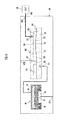
- Fig. 1 is a cross sectional view of the main portion of the fluid control device 100 according to the first embodiment of the present invention.
- Fig. 2 is an explanatory view showing the connection relationship among a piezoelectric pump 101, a check valve 102, an exhaust valve 103, and a cuff 109 that are shown in Fig. 1 .
- the fluid control device 100 has a structure in which the piezoelectric pump 101, a base plate 107, a valve housing 105 that forms, together with a diaphragm 108, a dustproof filter 105A, the check valve 102, and the exhaust valve 103, and a lid element 106 are laminated in this order.
- the piezoelectric pump 101, the check valve 102, and the exhaust valve 103 are formed integrally.
- the fluid control device 100 is equipped with the piezoelectric pump 101, the check valve 102, and the exhaust valve 103.
- the lid element 106 includes a cuff connection port 106A that communicates with an arm band rubber tube 109A of the cuff 109.
- a cuff connection port 106A that communicates with an arm band rubber tube 109A of the cuff 109.
- the base plate 107 includes a suction port 107A for sucking external air, an inflow path 107B for making the air that has passed the dustproof filter 105A flow into the piezoelectric pump 101, an outflow path 107C for making the air sent out from the piezoelectric pump 101 flow out into the valve housing 105, and an exhaust port 107D for exhausting the air in the cuff 109.
- a through hole 98 and a discharge hole 55 of the piezoelectric pump 101 so as to communicate with the inflow path 107B and the outflow path 107C of the base plate 107 and then connecting the piezoelectric pump 101 to the base plate 107 through the packing P, the base plate 107 is connected to the piezoelectric pump 101.
- the material of the diaphragm 108 may be an elastic element, such as ethylene propylene rubber or silicone rubber, for example.
- the fluid control device 100 makes the piezoelectric pump 101 perform the pumping operation when starting blood pressure measurement. Accordingly, the fluid control device 100 sucks external air from the suction port 107A and makes the air flow into a pump chamber 45 in the piezoelectric pump 101 through the dustproof filter 105A. Then, the fluid control device 100 sends out the air from the discharge hole 55 to the cuff 109 through the check valve 102 and increases the pressure (the air pressure) in the cuff 109.
- the fluid control device 100 stops the pumping operation of the piezoelectric pump 101, and makes the air in the cuff 109 exhaust rapidly from the exhaust port 107D through the fifth ventilation hole 34 and the third ventilation hole 32.
- the structure of the piezoelectric pump 101, the check valve 102, and the exhaust valve 103 is described in detail. To begin with, the structure of the piezoelectric pump 101 is described in detail with reference to Fig. 1 , Fig. 3 , and Fig. 4 .
- Fig. 3 is an exploded perspective view of the main portion of the piezoelectric pump 101 shown in Fig. 1
- Fig. 4 is a cross sectional view of the main portion of the piezoelectric pump 101 shown in Fig. 1 .
- the piezoelectric pump 101 is equipped with a base plate 91, a flat portion 51, a spacer 53A, a reinforcement plate 43, a vibrating plate unit 60, apiezoelectric element 42, a spacer 53B, an electrode conducting plate 70, a spacer 53C, and a lid portion 54, and has a structure in which the above mentioned elements are laminated in order.
- the piezoelectric element 42 is attached onto the upper surface of a disc shaped vibrating plate 41; the reinforcement plate 43 is attached onto the lower surface of the vibrating plate 41; and the vibrating plate 41, the piezoelectric element 42, and the reinforcement plate 43 form an actuator 40.
- the vibrating plate 41 is preferably formed of a metal plate that has a coefficient of linear expansion greater than the coefficients of linear expansion of the piezoelectric element 42 and the reinforcement plate 43 and cured by applying heat at time of adhesion, so that the entirety does not bend and an appropriate compressive stress can be left on the piezoelectric element 42, which prevents the piezoelectric element 42 from cracking.
- the vibrating plate 41 may be preferably made of a material having a greater coefficient of linear expansion such as phosphor bronze (C5210) and stainless steel SUS301, and the reinforcement plate 43 may be preferably formed of 42 nickel, 36 nickel, stainless steel SUS430 or the like.
- the thickness of the spacer 53B may preferably be the same as or slightly thicker than the thickness of the piezoelectric element 42.
- the vibrating plate 41, the piezoelectric element 42, and the reinforcement plate 43 may be placed from the top in order of the piezoelectric element 42, the reinforcement plate 43, and the vibrating plate 41.
- the coefficient of linear expansion is adjusted by inter changing the materials between the reinforcement plate 43 and the vibrating plate 41 so as to leave the appropriate compressive stress on the piezoelectric element 42.
- a vibrating plate support frame 61 is provided around the vibrating plate 41, and the vibrating plate 41 is linked to the vibrating plate support frame 61 by a link portion 62.
- the link portion 62 is formed in a thin ring shape and has an elastic structure having the elasticity of a small spring constant. Therefore, the vibrating plate 41 is flexibly supported preferably at two points against the vibrating plate support frame 61 by the two link portions 62. For this reason, the bending vibration of the vibrating plate 41 is not practically blocked. In other words, the peripheral portion of the actuator 40 (as well as the central portion) is not substantially fixed. It is to be noted the spacer 53A is provided in order to hold the actuator 40 while keeping a constant gap to the flat portion 51.
- the vibrating plate support frame 61 includes an external terminal 63 for electrical connection.
- the vibrating plate 41, the vibrating plate support frame 61, the link portion 62, and the external terminal 63 are molded through a stamping process of a metal plate, and these elements form a vibrating plate unit 60.
- the spacer 53B made of a resin material is adhesively fixed onto the upper surface of the vibrating plate support frame 61.
- the thickness of the spacer 53B is preferably the same as or slightly thicker than the thickness of the piezoelectric element 42, and the spacer 53B forms a portion of the pump housing 80 and electrically insulates the electrode conducting plate 70, described below, with the vibrating plate unit 60.
- the electrode conducting plate 70 made of a metal material is adhesively fixed on the spacer 53B.
- the electrode conducting plate 70 includes a frame portion 71 that is a nearly circular opening, an inner terminal 73 that projects into the opening, and an external terminal 72 that projects into the outside.
- the leading edge of the inner terminal 73 is soldered onto the surface of the piezoelectric element 42.
- the vibration of the inner terminal 73 can be suppressed by setting a soldering position to a position equivalent to a node of the bending vibration of the actuator 40.
- the spacer 53C made of a resin material is adhesively fixed on the electrode conducting plate 70.
- the spacer 53C in this embodiment, has a thickness that is similar to the thickness of the piezoelectric element 42.
- the spacer 53C is a spacer for preventing the soldered portion of the inner terminal 73 from contacting the lid portion 54 when the actuator vibrates.
- the spacer 53C also prevents the surface of the piezoelectric element 42 from excessively approaching to the lid portion 54 and thereby prevents vibration amplitude by air resistance from reducing. Therefore, the thickness of the spacer 53C may preferably be similar to the thickness of the piezoelectric element 42 as stated above.
- the lid portion 54 is put on the upper part of the spacer 53C and covers the surroundings of the actuator 40. For that reason, the fluid sucked in through a central ventilation hole 52 is discharged from the discharge hole 55. While the discharge hole 55 may be provided in the center of the lid portion 54, the discharge hole 55 for releasing positive pressure in the pump housing 80 including the lid portion 54 need not necessarily be provided in the center of the lid portion 54.
- a central ventilation hole 52 (a suction hole) is formed in the center of the flat portion 51.
- the spacer 53A is inserted, the spacer 53A having a thickness obtained by adding approximately several 10 micrometers to the thickness of the reinforcement plate 43.
- the spacer 53A since the vibrating plate 41 is not necessarily fixed by the vibrating plate support frame 61, a gap varies automatically according to load fluctuation.
- the fixed link portion 62 gives some influence, by inserting the spacer 53A in this way, a gap can be ensured positively and a flow rate can be increased at low load time.
- the link portion 62 bends at high load time, the gap of region as opposed to the actuator 40 and the flat portion 51 decreases automatically, which makes operation by high pressure possible.
- the link portion 62 is provided at two spots in the example shown in Fig. 3
- the link portion 62 may be provided at not less than three spots. Since the link portion 62 is not designed to block the vibration of the actuator 40, but gives some influence to the vibration, by linking (holding) at three spots, for example, a more natural hold becomes possible, which can prevent the piezoelectric element from cracking.
- the base plate 91 including a cylindrical shaped opening 92 formed in the center is provided in the lower part of the flat portion 51.
- a portion of the flat portion 51 is exposed at the opening 92 of the base plate 91.
- This circularly exposed portion can vibrate at a frequency substantially the same as a frequency of the actuator 40 by pressure fluctuation accompanying the vibration of the actuator 40.
- a portion that is positioned in the center or around the center of an actuator facing region of the flat portion 51 is a thin plate portion that can bend and vibrate, and a peripheral portion is a thick plate portion that is fixed substantially.
- This characteristic frequency of the circularly thin plate portion is designed to be the same as or slightly lower than the driving frequency of the actuator 40.
- the exposed portion of the flat portion 51 centering on the central ventilation hole 52 also vibrates with large amplitude. If the vibration phase of the flat portion 51 is a vibration phase delayed (90-delayed, for example) from the vibration phase of the actuator 40, the thickness fluctuation of a gap space between the flat portion 51 and the actuator 40 increases substantially. As a result, the pump performance can be improved.
- a cover plate portion 95 is provided in the lower part of the base plate 91 in the lower part of the base plate 91 in the lower part of the base plate 91.
- the cover plate portion 95 is formed by bonding a flow path plate 96 and a cover plate 99 together.
- the pump housing 80 includes a through hole 98. Consequently, the piezoelectric pump 101 has a shape in which an L character shaped communicating hole 97 that makes the inflow path 107B and the opening 92 communicate with each other is formed.
- Fig. 5 is a cross sectional view of the main part of the check valve 102 provided in the fluid control device 100 according to the first embodiment of the present invention.
- the check valve 102 has a cylindrical shaped first valve housing 21 and a first diaphragm 108A that consists of a circular shaped thin film.
- the first valve housing 21 includes a first ventilation hole 24 that communicates with a discharge hole 55 of the piezoelectric pump 101, a second ventilation hole 22 that communicates with the cuff 109, a sixth ventilation hole 27 that communicates with the second ventilation hole 22 and the cuff 109, and a valve seat 20 that is projected from the peripheral end of the second ventilation hole 22 to the first diaphragm 108A side.
- the first diaphragm 108A contacts the valve seat 20 and is fixed to the first valve housing 21. Accordingly, the first diaphragm 108A divides the inside of the first valve housing 21 and forms a ring shaped first valve chamber 23 that communicates with the first ventilation hole 24, and the second valve chamber 26 that communicates with the sixth ventilation hole 27.
- the valve seat 20 is formed in the first valve housing 21 so as to pressurize the first diaphragm 108A.
- the check valve 102 opens and closes the valve when the first diaphragm 108A contacts or separates from the valve seat 20 by a difference in pressure between the first valve chamber 23 and the second valve chamber 26.
- FIG. 6 is a cross sectional view of the main part of the exhaust valve 103 provided in the fluid control device 100 according to the first embodiment of the present invention.
- the exhaust valve 103 has a cylindrical shaped second valve housing 31 and a second diaphragm 108B that consists of a circular shaped thin film.
- the second valve housing 31 includes: a third ventilation hole 32 that communicates with the outside of the fluid control device 100; a fourth ventilation hole 37 that communicates with the discharge hole 55 of the piezoelectric pump 101. and the first ventilation hole 24; a fifth ventilation hole 34 that communicates with the cuff 109, the second ventilation hole 22, and the sixth ventilation hole 27; and a valve seat 30 that is projected from the peripheral end of the third ventilation hole 32 to the second diaphragm 108B side.
- the second diaphragm 108B contacts the valve seat 30 and is fixed to the second valve housing 31. Accordingly, the second diaphragm 108B divides the inside of the second valve housing 31 and forms a ring shaped third valve chamber 33 that communicates with the fifth ventilation hole 34, and a fourth valve chamber 36 that communicates with the fourth ventilation hole 37.
- the exhaust valve 103 opens and closes the valve when the second diaphragm 108B contacts or separates from the valve seat 30 by a difference in pressure between the third valve chamber 33 and the fourth valve chamber 36.
- first valve chamber 23 and the fourth valve chamber 36 are equivalent to the "first region” of the present invention
- second valve chamber 26 and the third valve chamber 33 are equivalent to the "second region” of the present invention.
- Fig. 7 is an explanatory view showing a flow of air when the piezoelectric pump 101 shown in Fig. 1 is performing a pumping operation.
- Fig. 8 is an explanatory view showing a flow of air immediately after the piezoelectric pump 101 shown in Fig. 1 stops the pumping operation.
- Fig. 9 is a cross sectional view of the main part of the exhaust valve 103 at time of opening the valve, provided in the fluid control device 100 according to the first embodiment of the present invention.
- Fig. 10 is a graph showing a change in pressure of the cuff 109 in a state in which the piezoelectric pump 101 shown in Fig. 1 is driven.
- Fig. 10 is a graph showing a change in pressure of the cuff 109 in a state in which the piezoelectric pump 101 shown in Fig. 1 is driven.
- Fig. 11 is a graph showing an enlarged section from Time 39 seconds to Time 43 seconds that are shown in Fig. 10 .
- Fig. 12 is a graph showing a change in pressure of the cuff 109 in a state in which the piezoelectric pump 101 is driven when the discharge hole 55 of the piezoelectric pump 101 is directly connected to the cuff 109.
- the fluid control device 100 makes the piezoelectric pump 101 perform the pumping operation when starting the blood pressure measurement. Accordingly, the piezoelectric pump 101 sucks external air from the suction port 107A and makes the air flow into the pump chamber 45 in the piezoelectric pump 101 through the dustproof filter 105A (see Fig. 1 ). Then, the piezoelectric pump 101 makes the air flow from the discharge hole 55 of the piezoelectric pump 101 into the check valve 102. In the check valve 102, the discharge pressure in the forward direction from the first ventilation hole 24 to the second ventilation hole 22 is generated by the pumping operation of the piezoelectric pump 101, so that the pressure of the first valve chamber 23 becomes higher than the pressure of the second valve chamber 26.
- the first diaphragm 108A opens and makes the first ventilation hole 24 and the second ventilation hole 22 communicate with each other.
- the pressure of the fourth valve chamber 36 rises by the pumping operation of the piezoelectric pump 101, so that the pressure of the fourth valve chamber 36 becomes higher than the pressure of the third valve chamber 33.
- the second diaphragm 108B seals the third ventilation hole 32 and blocks out ventilation between the fifth ventilation hole 34 and the second ventilation hole 22, and the third ventilation hole 32.
- the air is sent out from the piezoelectric pump 101 to the cuff 109 through the first ventilation hole 24 and the second ventilation hole 22 of the check valve 102 (see Fig. 7 ), and the pressure (the air pressure) in the cuff 109 increases.
- the fluid control device 100 has a structure in which the second ventilation hole 22 and the sixth ventilation hole 27 of the check valve 102 communicate with each other.
- the check valve 102 has a shape in which the first ventilation hole 24 is formed in the outer periphery, centering on the second ventilation hole 22. Accordingly, the air that flows out of the second ventilation hole 22 through the first ventilation hole 24 of the check valve 102 becomes a pressure slightly lower than the discharge pressure of the piezoelectric pump 101 and flows from the sixth ventilation hole 27 into the second valve chamber 26. On the other hand, the discharge pressure of the piezoelectric pump 101 is applied to the first valve chamber 23.
- the pressure of the first valve chamber 23 is slightly higher than the pressure of the second valve chamber 26, and the first diaphragm 108A is kept open in the check valve 102. Additionally, since the difference in pressure between the first valve chamber 23 and the second valve chamber 26 is small, the difference in pressure is not extremely deviated, so that the first diaphragm 108A can be prevented from being damaged.
- the fluid control device 100 has a structure in which the second ventilation hole 22 of the check valve 102 and the fifth ventilation hole 34 of the exhaust valve 103 communicate with each other.
- the exhaust valve 103 has a shape in which the fifth ventilation hole 34 is formed in the outer periphery, centering on the third ventilation hole 32. Accordingly, the air that flows out of the second ventilation hole 22 through the first ventilation hole 24 of the check valve 102 becomes a pressure slightly lower than the discharge pressure of the piezoelectric pump 101 and flows from the fifth ventilation hole 34 into the third valve chamber 33 of the exhaust valve 103.
- the discharge pressure of the piezoelectric pump 101 is applied to the fourth valve chamber 36.
- the pressure of the fourth valve chamber 36 is slightly higher than the pressure of the third valve chamber 33, and the second diaphragm 108B is kept close in the exhaust valve 103.
- the difference in pressure between the fourth valve chamber 36 and the third valve chamber 33 is small, the difference in pressure is not extremely deviated, so that the second diaphragm 108B can be prevented from being damaged.
- the fluid control device 100 stops the pumping operation of the piezoelectric pump 101.
- the volume of the pump chamber 45, the first valve chamber 23, and the fourth valve chamber 36 is extremely small as compared with the volume of the air that can be stored in the cuff 109. Therefore, when the pumping operation of the piezoelectric pump 101 stops, the air in the pump chamber 45, the first valve chamber 23, and the fourth valve chamber 36 is immediately exhausted from the suction port 107A of the fluid control device 100 to the outside of the fluid control device 100 through the central ventilation hole 52 and the opening 92 of the piezoelectric pump 101.
- the pressure of the cuff 109 is applied to the second valve chamber 26 and the third valve chamber 33.
- the first diaphragm 108A abuts against the valve seat 20 and seals the second ventilation hole 22.
- the second diaphragm 108B opens and makes the fifth ventilation hole 34 and the third ventilation hole 32 communicate with each other. This enables the air in the cuff 109 to be rapidly exhausted from the exhaust port 107D through the fifth ventilation hole 34 and the third ventilation hole 32 (see Fig. 10 and Fig. 11 ).
- Fig. 10 and Fig. 11 show the exhaustion of the air in the cuff 109 will be completed in two seconds after the pumping operation of the piezoelectric pump 101 is stopped.
- the fluid control device 100 equipped with the check valve 102 and the exhaust valve 103 can also achieve a similar effect .
- an electromagnetic valve which is hard to be miniaturized and a driver circuit that drives the electromagnetic valve are not provided, so that a small and low profile fluid control device 100 can be provided with low manufacturing costs and small power consumption.
- the actuator having a unimorph type structure and undergoing bending vibration was preferably provided in the above described preferred embodiment, it may be possible to attach a piezoelectric element on both sides of the vibrating plate so as to have a bimorph type structure and undergo bending vibration.
- valve seat 20 of the check valve 102 is formed in the peripheral end of the second ventilation hole 22
- valve seat 20 may be formed in the peripheral end of the first ventilation hole 24 in the event of the operation.
- valve seat 30 of the exhaust valve 103 is formed in the peripheral end of the third ventilation hole 32
- the valve seat 30 may be formed in the peripheral end of the fifth ventilation hole 34 in the event of the operation.
- the exhaust valve 103 may connect the fifth ventilation hole 34 placed in the position of the third ventilation hole 32 of Fig. 2 to the cuff 109, and may connect the third ventilation hole 32 placed in the position of the fifth ventilation hole 34 of Fig. 2 to the exhaust port 107D.
- this connection method even in a case in which the pressure of the cuff 109 varies due to a body motion and the like, an advantage that unintended exhaust is unlikely to occur is attained.
- the diaphragm 108A that made of a circular shaped thin film as a valve element of the check valve 102 is employed, other shapes (such as a mushroom shape, a rectangle shape, for example) capable of sealing the valve seat 20 may be employed in the event of the operation.
- a fluid control device 200 according to a second embodiment of the present invention will be described.
- This second embodiment is different from the above described first embodiment in that the check valve 102 and the exhaust valve 103 that are shown in Fig. 2 are replaced with a valve 203 and is the same as the above described first embodiment in other configurations.
- Fig. 13 is an explanatory view showing a connection relationship among a piezoelectric pump 101, the valve 203, and a cuff 109 that are included in a fluid control device 200 according to a second embodiment of the present invention.
- the valve 203 is an integrated valve that preferably includes the check valve 102 and the exhaust valve 103 that are shown in Fig. 2 , and has a cylindrical shaped valve housing 231 and a diaphragm 208 that made of a circular shaped thin film.
- the valve housing 231 includes: a first ventilation hole 211 that communicates with the discharge hole 55 of the piezoelectric pump 101; a second ventilation hole 212 that communicates with the cuff 109; a third ventilation hole 213 that communicates with the outside of the fluid control device 200; a communicating hole 214 that communicates with the second ventilation hole 212 and the cuff 109; a valve seat 220 that is projected from the peripheral end of the second ventilation hole 212 to the diaphragm 208 side; and a valve seat 230 that is projected from the peripheral end of the third ventilation hole 213 to the diaphragm 108 side.
- the diaphragm 208 contacts the valve seats 220 and 230 and is fixed to the valve housing 231. Accordingly, the diaphragm 208 divides the inside of the valve housing 231 and forms a ring shaped lower valve chamber 223 that communicates with the first ventilation hole 211, and the ring shaped upper valve chamber 233 that communicates with a communicating hole 214.
- the valve seat 220 is formed in the valve housing 231 so as to pressurize the diaphragm 208.
- the valve 203 opens and closes the valve when the diaphragm 208 contacts or separates from the valve seat 220 by a difference in pressure between the lower valve chamber 223 and the upper valve chamber 233.
- the valve 203 opens and closes the valve when the diaphragm 208 contacts or separates from the valve seat 230 by the difference in pressure between the upper valve chamber 233 and the lower valve chamber 223.
- the lower valve chamber 223 is equivalent to the "first region” of the present invention
- the upper valve chamber 233 is equivalent to the "second region” of the present invention.
- Fig. 14 is an explanatory view showing a flow of air when the piezoelectric pump 101 shown in Fig. 13 is performing a pumping operation.
- Fig. 15 is an explanatory view showing a flow of air immediately after the piezoelectric pump 101 shown in Fig. 13 stops the pumping operation.
- the fluid control device 200 makes the piezoelectric pump 101 perform the pumping operation when starting the blood pressure measurement. Accordingly, the piezoelectric pump 101 sucks external air from a suction port 107A and makes the air flow into a pump chamber 45 in the piezoelectric pump 101. Then, the piezoelectric pump 101 makes the air flow from the discharge hole 55 of the piezoelectric pump 101 into the valve 203. In the valve 203, the discharge pressure in the forward direction from the first ventilation hole 211 to the second ventilation hole 212 is generated by the pumping operation of the piezoelectric pump 101, so that the pressure of the lower valve chamber 223 becomes higher than the pressure of the upper valve chamber 233.
- the diaphragm 208 opens the second ventilation hole 212 and makes the first ventilation hole 211 and the second ventilation hole 212 communicate with each other, and the diaphragm 208 seals the third ventilation hole 213 and blocks the ventilation between the communicating hole 214 and the second ventilation hole 212, and the third ventilation hole 213.
- the air is sent out from the piezoelectric pump 101 to the cuff 109 through the first ventilation hole 211 and the second ventilation hole 212 of the valve 203 (see Fig. 14 ), and the pressure (the air pressure) in the cuff 109 increases.
- the fluid control device 200 has a structure in which the second ventilation hole 212 and the communicating hole 214 of the valve 203 communicate with each other.
- the valve 203 has a shape in which the first ventilation hole 211 is formed in the outer periphery, centering on the second ventilation hole 212. Accordingly, the air that flows out of the second ventilation hole 212 through the first ventilation hole 211 of the valve 203 becomes a pressure slightly lower than the discharge pressure of the piezoelectric pump 101 and flows from the communicating hole 214 into the upper valve chamber 233. On the other hand, the discharge pressure of the piezoelectric pump 101 is applied to the lower valve chamber 223.
- the pressure of the lower valve chamber 223 is slightly higher than the pressure of the upper valve chamber 233, and, in the valve 203, the diaphragm 208 seals the thirdventilation hole 213 and the secondventilation hole 212 is kept open. Additionally, since a difference in pressure between the lower valve chamber 223 and the upper valve chamber 233 is small, the difference in pressure is not extremely deviated, so that the diaphragm 208 can be prevented from being damaged.
- the fluid control device 200 stops the pumping operation of the piezoelectric pump 101.
- the volume of the pump chamber 45 and the lower valve chamber 223 is extremely small as compared with the volume of the air that can be stored in the cuff 109. Therefore, when the pumping operation of the piezoelectric pump 101 stops, the air in the pump chamber 45 and the lower valve chamber 223 is immediately exhausted from the suction port 107A of the fluid control device 200 to the outside of the fluid control device 200 through the central ventilation hole 52 and the opening 92 of the piezoelectric pump 101. In addition, the pressure of the cuff 109 is applied to the upper valve chamber 233. As a result, in the valve 203, after the pumping operation of the piezoelectric pump 101 stops, the pressure of the lower valve chamber 223 is immediately reduced lower than the pressure of the upper valve chamber 233.
- valve 203 when the pressure of the lower valve chamber 223 is reduced lower than the pressure of the upper valve chamber 233, the diaphragm 208 abuts against the valve seat 220 and seals the second ventilation hole 212, and opens the third ventilation hole 213 and makes the communicating hole 214 and the third ventilation hole 213 communicate with each other. This enables the air in the cuff 109 to be rapidly exhausted from an exhaust port 207D formed in the housing of the fluid control device 200 through the communicating hole 214 and the third ventilation hole 213 (see Fig. 15 ).
- valve 203 and the fluid control device 200 according to the present embodiment make it possible to achieve an effect similar to the effect that can be achieved by the first embodiment. Furthermore, since the valve 203 is an integrated valve that preferably includes the check valve 102 and the exhaust valve 103 that are shown in Fig. 2 , and the valve 203 and the fluid control device 200 according to the present embodiment can reduce the size.
- a fluid control device 300 according to a third embodiment of the present invention will be described.
- This third embodiment is different from the above described second embodiment in the structure of a valve 303 and is the same as the above described second embodiment in other configurations.
- Fig. 16 is an explanatory view showing a connection relationship among a piezoelectric pump 101, the valve 303, and a cuff 109 that are included in the fluid control device 300 according to the third embodiment of the present invention.
- the valve 303 is a deformed version of the valve 203 shown in Fig. 13 , and has a cylindrical shaped valve housing 331 and a diaphragm 308 that is made of a circular shaped thin film.
- the valve housing 331 includes: a first ventilation hole 211 that communicates with the discharge hole 55 of the piezoelectric pump 101; a second ventilation hole 312 that communicates with the cuff 109; a third ventilation hole 213 that communicates with the outside of the fluid control device 300; a valve seat 230 that is projected from the peripheral end of the third ventilation hole 213 to the diaphragm 308 side; and a projecting portion 332 that is projected to the diaphragm 308 side.
- the diaphragm 308 includes a hole portion 309 in a part of a region that is opposed to the projecting portion 332.
- the diaphragm 308 is fixed to the valve housing 331 so as to contact the valve seat 230 and make the peripheral end of the hole portion 309 contact the projecting portion 332. Accordingly, the diaphragm 308 divides the inside of the valve housing 331 and forms a ring shaped lower valve chamber 223 that communicates with the first ventilation hole 211, and a ring shaped upper valve chamber 233 that communicates with the second ventilation hole 312.
- the projecting portion 332 is formed in the valve housing 331 so as to pressurize the peripheral end of the hole portion 309 in the diaphragm 308.
- the valve 303 opens and closes the valve when the diaphragm 308 contacts or separates from the projecting portion 332 by a difference in pressure between the lower valve chamber 223 and the upper valve chamber 233.
- the valve 303 opens and closes the valve when the diaphragm 308 contacts or separates from the valve seat 230 by the difference in pressure between the upper valve chamber 233 and the lower valve chamber 223.
- the lower valve chamber 223 is equivalent to the "first region” of the present invention
- the upper valve chamber 233 is equivalent to the "second region” of the present invention.
- Fig. 17 is an explanatory view showing a flow of air when the piezoelectric pump 101 shown in Fig. 16 is performing a pumping operation.
- Fig. 18 is an explanatory view showing a flow of air immediately after the piezoelectric pump 101 shown in Fig. 16 stops the pumping operation.
- the fluid control device 300 makes the piezoelectric pump 101 perform the pumping operation when starting blood pressure measurement. Accordingly, the piezoelectric pump 101 sucks external air from a suction port 107A and makes the air flow into a pump chamber 45 in the piezoelectric pump 101. Then, the piezoelectric pump 101 makes the air flow from the discharge hole 55 of the piezoelectric pump 101 into the valve 303. In the valve 303, the discharge pressure in the forward direction from the first ventilation hole 211 to the second ventilation hole 312 is generated by the pumping operation of the piezoelectric pump 101, so that the pressure of the lower valve chamber 223 becomes higher than the pressure of the upper valve chamber 233.
- the diaphragm 308 separates from the projecting portion 332 and makes the first ventilation hole 211 and the second ventilation hole 312 communicate through the hole portion 309, and the diaphragm 308 seals the third ventilation hole 213 and blocks the ventilation between the second ventilation hole 312 and the third ventilation hole 213.
- the air is sent out from the piezoelectric pump 101 to the cuff 109 through the first ventilation hole 221, the hole portion 309, and the second ventilation hole 312 of the valve 303 (see Fig. 17 ), and the pressure (the air pressure) in the cuff 109 increases.
- the diaphragm 308 is fixed to the valve housing 331 so that the peripheral end of the hole portion 309 contacts the projecting portion 332. Then, this projecting portion 332 pressurizes the peripheral end of the hole portion 309 in the diaphragm 308. Accordingly, the air that flows out of the hole portion 309 through the first ventilation hole 211 of the valve 303 becomes a pressure slightly lower than the discharge pressure of the piezoelectric pump 101 and flows from the hole portion 309 into the upper valve chamber 233. On the other hand, the discharge pressure of the piezoelectric pump 101 is applied to the lower valve chamber 223.
- the pressure of the lower valve chamber 223 is slightly higher than the pressure of the upper valve chamber 233, and, in the valve 303, the diaphragm 308 seals the third ventilation hole 213 and the hole portion 309 is kept open. Additionally, since the difference in pressure between the lower valve chamber 223 and the upper valve chamber 233 is small, the difference in pressure is not extremely deviated, so that the diaphragm 308 can be prevented from being damaged.
- the fluid control device 300 stops the pumping operation of the piezoelectric pump 101.
- the air in the pump chamber 45 and the lower valve chamber 223 is immediately exhausted from the suction port 107A of the fluid control device 300 to the outside of the fluid control device 300 through the central ventilation hole 52 and the opening 92 of the piezoelectric pump 101.
- the pressure of the cuff 109 is applied to the upper valve chamber 233 from the second ventilation hole 312.
- the pressure of the lower valve chamber 223 is immediately reduced lower than the pressure of the upper valve chamber 233.
- valve 303 when the pressure of the lower valve chamber 223 is reduced lower than the pressure of the upper valve chamber 233, the diaphragm 308 abuts against the projecting portion 332 and seals the hole portion 309, and opens the third ventilation hole 213 and makes the second ventilation hole 312 and the third ventilation hole 213 communicate with each other.
- This enables the air in the cuff 109 to be rapidly exhausted from the exhaust port 207D through the second ventilation hole 312 and the third ventilation hole 213 (see Fig. 18 ). Therefore, the valve 303 and the fluid control device 300 according to the present embodiment make it possible to achieve an effect similar to the effect that can be achieved by the second embodiment.
- FIG. 19 is a cross sectional view of a main portion of the fluid control device 350 according to the modification example of the third embodiment of the present invention.
- Fig. 20 and Fig. 21 are exploded perspective views of a valve 353 shown in Fig. 19 .
- Fig. 20 is the exploded perspective view of the valve 353 as viewed from the upper surface side that is connected to the cuff 109
- Fig. 21 is the exploded perspective view of the valve 353 as viewed from the bottom side that is bonded to a piezoelectric pump 301.
- the fluid control device 350 is formed of the piezoelectric pump 301 and the valve 353.
- This piezoelectric pump 301 is different from the above described piezoelectric pump 101 in that two discharge holes 55 and 56 are formed, and is the same as the above described piezoelectric pump 101 in other configurations.
- the valve 353 is a deformed version of the valve 303 shown in Fig. 16 and an integrated valve that preferably includes the check valve 102 and the exhaust valve 103 that are shown in Fig. 2 .
- the valve 353, as shown in Fig. 19 , Fig. 20 , and Fig. 21 , has a structure in which a lower valve housing 392, a diaphragm 358 that is made of a rectangular shaped thin film, and an upper valve housing 391 are laminated in this order.
- the upper valve housing 391 and the lower valve housing 392 are equivalent to the valve housing 381.
- the lower valve housing 392 includes: a first ventilation hole 361 that communicates with the discharge hole 56 of the piezoelectric pump 301; a fourth ventilation hole 360 that communicates with the discharge hole 55 of the piezoelectric pump 301; and a projecting portion 382 that is projected to the diaphragm 358 side.
- the upper valve housing 39 includes: a second ventilation hole 362 that communicates with the cuff 109; a third ventilation hole 363 that communicates with the outside of the fluid control device 350, and a valve seat 380 that is projected from the peripheral end of the third ventilation hole 363 to the diaphragm 358 side.
- the diaphragm 358 as shown in Fig. 19 , Fig. 20 , and Fig. 21 , includes a hole portion 359 in a part of a region as opposed to the projecting portion 382.
- the diaphragm 358 is held by the upper valve housing 391 and the lower valve housing 392 from the both sides and is fixed to the upper valve housing 391 and the lower valve housing 392 so as to contact the valve seat 380 and make the peripheral end of the hole portion 359 contact the projecting portion 382.
- the diaphragm 358 divides the inside of the valve housing 381 and forms: a cylindrical shaped first lower valve chamber 372 that communicates with a first ventilation hole 361; a ring shaped second lower valve chamber 373 that communicates with a fourth ventilation hole 360; a cylindrical shaped first upper valve chamber 383 that communicates with a second ventilation hole 362 through a communicating path 385; and a ring shaped second upper valve chamber 384 that communicates with the first upper valve chamber 383 through the communicating path 385. Therefore, during the pumping operation of the piezoelectric pump 301, the air discharged out of the discharge holes 55 and 56 of the piezoelectric pump 301, as shown in Fig. 19 , flows into both the first lower valve chamber 372 and the second lower valve chamber 373.
- the projecting portion 382 is formed in the lower valve housing 392 so as to pressurize the peripheral end of the hole portion 359 in the diaphragm 358.
- the valve 353 opens and closes the valve when the diaphragm 358 contacts or separates from the projecting portion 382 by a difference in pressure between the first lower valve chamber 372 and the second lower valve chamber 373, and the first upper valve chamber 383 and the second lower valve chamber 384.
- the valve 353 opens and closes the valve when the diaphragm 358 contacts or separates from the valve seat 380 by the difference in pressure between the first lower valve chamber 372 and the second lower valve chamber 373, and the first upper valve chamber 383 and the second lower valve chamber 384.
- valve 353 and the fluid control device 350 according to the present modification example make it possible to achieve an effect similar to the effect that can be achieved by the second embodiment.
- the valve 353 according to the present modification example since each of the regions 358A, 358B, 358C, and 358D of the diaphragm 358 facing each of the valve chambers 372, 373, 383, and 384 has a circular shape, as shown in Figs. 20 and 21 , the tension of the diaphragm 358 is applied uniformly.
- each valve can be more reliably opened and closed.
- a fluid control device 400 according to a fourth embodiment of the present invention will be described.
- This fourth embodiment is different from the above described third embodiment in that a piezoelectric pump 401 and a valve 403 are directly connected to each other, and is the same as the above described third embodiment in other configurations.
- Fig. 22 is an explanatory view showing a connection relationship among the piezoelectric pump 401, the valve 403, and a cuff 109 that are included in a fluid control device 400 according to the fourth embodiment of the present invention.
- Fig. 23 is an explanatory view showing a flow of air when the piezoelectric pump 401 shown in Fig. 22 is performing a pumping operation.
- Fig. 24 is an explanatory view showing a flow of air immediately after the piezoelectric pump 401 shown in Fig. 22 stops the pumping operation.
- a complex of the piezoelectric pump 401 and the valve 403 is an integral structure that preferably includes the piezoelectric pump 101 and the valve 303 that are shown in Fig. 16 . More specifically, the complex of the piezoelectric pump 401 and the valve 403 has a structure in which the spacer 53C of the piezoelectric pump 101 shown in Fig. 4 is removed, and the lid portion 54 is replaced with a valve housing 431 having a shape in which the first ventilation hole 211 of the valve housing 331 as shown in Fig. 16 is expanded; and is the same in other configurations as the piezoelectric pump 101 as shown in Fig. 4 .
- the diaphragm 308 divides the inside of the valve housing 403 and forms a lower valve chamber 423 that communicates with a suction hole 52, and a ring shaped upper valve chamber 233 that communicates with the second ventilation hole 312. Additionally, the pump chamber 145 and the lower valve chamber 423 of the piezoelectric pump 401 communicate with each other.
- the valve 403 opens and closes the valve when the diaphragm 308 contacts or separates from the projecting portion 332 by a difference in pressure between the lower valve chamber 423 and the upper valve chamber 233.
- the valve 403 opens and closes the valve when the diaphragm 308 contacts or separates from the valve seat 230 by the difference in pressure between the upper valve chamber 233 and the lower valve chamber 423.
- the fluid control device 400 according to the present embodiment makes it possible to achieve an effect similar to the effect that can be achieved by the third embodiment. Additionally, in the valve 403 according to the present embodiment, direct connection of the valve 403 and the piezoelectric pump 401 used as a pressure generating means increases the pressure of the lower valve chamber 423. Therefore, the fluid control device 400 of the present embodiment can further miniaturize the main body of the apparatus.
- the lower valve chamber 423 is equivalent to the "first region” of the present invention
- the upper valve chamber 233 is equivalent to the "second region” of the present invention.
- the pump chamber 145 and the lower valve chamber 423 of the piezoelectric pump 401 are directly connected to each other and integrated into one body, the vicinity of the position in which the pump chamber 145 and the lower valve chamber 423 are connected is defined as "the first ventilation hole" of the present invention.
- a fluid control device 500 according to a fifth embodiment of the present invention will be described.
- This fifth embodiment is different from the above described second embodiment in the structure of a valve 503, and is the same as the above described second embodiment in other configurations.
- Fig. 25 is an explanatory view showing a connection relationship among a piezoelectric pump 101, the valve 503, and a cuff 109 that are included in a fluid control device 500 according to the fifth embodiment of the present invention.
- Fig. 26 is an explanatory view showing a flow of air when the piezoelectric pump 101 shown in Fig. 25 is performing a pumping operation.
- Fig. 27 is an explanatory view showing a flow of air immediately after the piezoelectric pump 101 shown in Fig. 25 stops the pumping operation.
- This valve 503 is a deformed version of the valve 203 shown in Fig. 13 , and has a cylindrical shaped valve housing 531 and a diaphragm 508 that is made of a circular shaped thin film.
- the valve housing 531 in the same manner as the valve housing 231 of the valve 203 as shown in Fig. 13 , includes a first ventilation hole 211, a second ventilation hole 212, a third ventilation hole 213, a communicating hole 214, and valve seats 220 and 230.
- valve housing 531 includes a valve seat 510 that is projected from the peripheral end of the first ventilation hole 211 to the diaphragm 508 side.
- This valve seat 510 and the valve seat 220 have the same shape and the same height H.
- the valve housing 531 including this valve seat 510 includes a cutout 532, the first ventilation hole 211 always communicates with the lower valve chamber 523.
- the positional relationship among the first ventilation hole 211, the second ventilation hole 212, and the third ventilation hole 213 in the valve housing 531 will be described in detail.
- the third ventilation hole 213 is formed in the center of the valve housing 531.
- the first ventilation hole 211 and the second ventilation hole 212 are formed in a position of the valve housing 531, the position being in which a length L from the center of the first ventilation hole 211 to the center of the third ventilation hole 213 becomes the same as a length L from the center of the third ventilation hole 213 to the center of the second ventilation hole 212.
- the diaphragm 508 is fixed to the valve housing 531 so as to contact the valve seats 220, 230, and 510. Accordingly, the diaphragm 508 divides the inside of the valve housing 531 and forms a lower valve chamber 523 and a ring shaped upper valve chamber 533 that communicates with a communicating hole 214. It should be noted, in the present embodiment, the lower valve chamber 523 is equivalent to the "first region" of the present invention, and the upper valve chamber 533 is equivalent to the "second region" of the present invention.
- the valve 503 opens and closes the valve when the diaphragm 508 contacts or separates from the valve seat 220 by a difference in pressure between the lower valve chamber 523 and the upper valve chamber 533.
- the valve housing 531 includes a cutout 532, the first ventilation hole 211 always communicates with the lower valve chamber 523.
- the valve 503 opens and closes the valve when the diaphragm 508 contacts or separates from the valve seat 230 by the difference in pressure between the upper valve chamber 533 and the lower valve chamber 523.
- valve 503 and the fluid control device 500 make it possible to achieve an effect similar to the effect that can be achieved by the second embodiment. Furthermore, according to the valve 503 and the fluid control device 500 of the present embodiment, the diaphragm 508 is in close contact with the valve seat 230 of the third ventilation hole 213 in parallel, so that the air from the upper valve chamber 533 to the third ventilation hole 213 can be prevented from leaking and rapid exhaustion of the air can be further stabilized.
- a disc shaped packing 239 may be provided in a position as opposed to the valve seat 230 of the diaphragm 508.
- the packing 239 is made of an elastic body harder than the diaphragm 508.
- the diaphragm 508 can be prevented from being deformed when the diaphragm 508 closes the third ventilation hole 213.
- valve 504 since the valve seat 230 and the packing 239 are in close contact with each other when the diaphragm 508 closes the third ventilation hole 213, aircanbefurtherpreventedfromleaking. Furthermore, in the valve 504, since the packing 239 of the diaphragm 508 can be moved in parallel apart from the valve seat 230, the valve is stably opened and rapid exhaustion of the air can be further stabilized.
- a fluid control device 600 according to a sixth embodiment of the present invention will be described.
- This sixth embodiment is different from the above described fifth embodiment in regards to the structure of a valve 603, and is the same as the above described fifth embodiment in other configurations.
- Fig. 29 is an explanatory view showing a connection relationship among a piezoelectric pump 101, the valve 603, and a cuff 109 that are included in the fluid control device 600 according to the sixth embodiment of the present invention.
- Fig. 30 is an explanatory view showing a flow of air when the piezoelectric pump 101 shown in Fig. 29 is performing a pumping operation.
- Fig. 31 is an explanatory view showing a flow of air immediately after the piezoelectric pump 101 shown in Fig. 29 stops the pumping operation.
- This valve 603 is a valve obtained by combining the valve 503 shown in Fig. 25 and the valve 303 shown in Fig. 16 .
- valve housing 631 in the same manner as the valve 503 as shown in Fig. 25 , includes a first ventilation hole 211, a third ventilation hole 213, and valve seats 230 and 510. Furthermore, the valve housing 631, in the same manner as the valve 303 as shown in Fig. 16 , includes a second ventilation hole 312 and a projecting portion 332 that is projected to the diaphragm 608 side. This projecting portion 332 and the valve seat 510 have the same height H. In this regard, since the valve housing 631 including this valve seat 510 also includes a cutout 532, the first ventilation hole 211 always communicates with the lower valve chamber 523.
- the third ventilation hole 213 is formed in the center of the valve housing 531.
- the first ventilation hole 211 and the projecting portion 332 are formed in a position of the valve housing 631, the position being in which a length L from the center of the first ventilation hole 211 to the center of the third ventilation hole 213 becomes the same as a length L from the center of the third ventilation hole 213 to the center of the projecting portion 332.
- the diaphragm 608 in the same manner as the valve 303 as shown in Fig. 16 , includes a hole portion 309 in a part of a region as opposed to the projecting portion 332.
- the diaphragm 608 is fixed to the valve housing 631 so as to contact the valve seats 230 and 510 and make the peripheral end of the hole portion 309 contact the projecting portion 332. Accordingly, the diaphragm 608 divides the inside of the valve housing 631 and forms a lower valve chamber 523 and a ring shaped upper valve chamber 533 that communicates with the second ventilation hole 312.
- the projecting portion 332 is formed in the valve housing 631 so as to pressurize the peripheral end of the hole portion 309 in the diaphragm 608.
- the valve 603 opens and closes the valve when the diaphragm 608 contacts or separates from the projecting portion 332 by a difference in pressure between the lower valve chamber 523 and the upper valve chamber 533.
- the valve 603 opens and closes the valve when the diaphragm 608 contacts or separates from the valve seat 230 by the difference in pressure between the upper valve chamber 533 and the lower valve chamber 523.
- valve 603 and the fluid control device 600 make it possible to achieve an effect similar to the effect that can be achieved by the above described third embodiment. Furthermore, according to the valve 603 and the fluid control device 600 of the present embodiment, the diaphragm 608 is in close contact with the valve seat 230 of the third ventilation hole 213 in parallel, so that the air can be prevented from leaking and rapid exhaustion of the air can be further stabilized.
- a disc shaped packing 239 may be provided in a position as opposed to the valve seat 230 of the diaphragm 608.
- the packing 239 is made of an elastic body harder than the diaphragm 608.
- the valve 604 equipped with this packing 239 makes it possible to achieve an effect similar to the effect that can be achieved by the valve 504 equipped with the packing 239 as shown in Fig. 28 .
- a fluid control device 700 according to a seventh embodiment of the present invention will be described.
- This seventh embodiment is different from the above described second embodiment in the structure of a valve 703, and is the same as the above described second embodiment in other configurations.
- Fig. 33 is an explanatory view showing a connection relationship among a piezoelectric pump 101, the valve 703, and a cuff 109 that are included in the fluid control device 700 according to the seventh embodiment of the present invention.
- Fig. 34 is an explanatory view showing a flow of air when the piezoelectric pump 101 shown in Fig. 33 is performing a pumping operation.
- Fig. 35 is an explanatory view showing a flow of air immediately after the piezoelectric pump 101 shown in Fig. 33 stops the pumping operation.
- This valve 703 is a deformed version of the valve 203 shown in Fig. 13 , and has a cylindrical shaped valve housing 731 and a diaphragm 708 that is made of a circular shaped thin film.
- the valve housing 731 in the same manner as the valve housing 231 of the valve 203 as shown in Fig. 13 , includes a first ventilation hole 211, a second ventilation hole 212, a third ventilation hole 213, a communicating hole 214, and valve seats 220 and 230.
- valve housing 731 includes a valve seat 730 that is projected from the peripheral end of the communicating hole 214 to the diaphragm 708 side.
- This valve seat 730 and the valve seat 230 have the same shape and the same height H.
- the valve housing 731 including this valve seat 730 includes a cutout 732, the communicating hole 214 always communicates with the upper valve chamber 733.
- the second ventilation hole 212 is formed in the center of the valve housing 731.
- the third ventilation hole 213 and the communicating hole 214 are formed in a position of the valve housing 731, the position being in which a length L from the center of the third ventilation hole 213 to the center of the second ventilation hole 212 becomes the same as a length L from the center of the second ventilation hole 212 to the center of the communicating hole 214.
- the diaphragm 708 is fixed to the valve housing 731 so as to contact the valve seats 220, 230, and 730. Accordingly, the diaphragm 708 divides the inside of the valve housing 731 and forms a ring shaped lower valve chamber 723 that communicates with the first ventilation hole 211, and a upper valve chamber 733. It should be noted, in the present embodiment, the lower valve chamber 723 is equivalent to the "first region" of the present invention, and the upper valve chamber 733 is equivalent to the "second region" of the present invention.
- valve 703 opens and closes the valve when the diaphragm 708 contacts or separates from the valve seat 220 by a difference in pressure between the lower valve chamber 723 and the upper valve chamber 733.
- valve 703 opens and closes the valve when the diaphragm 708 contacts or separates from the valve seat 230 by the difference in pressure between the upper valve chamber 733 and the lower valve chamber 723.
- valve 703 and the fluid control device 700 make it possible to achieve an effect similar to the effect that can be achieved by the second embodiment. Furthermore, according to the valve 703 and the fluid control device 700 of the present embodiment, the diaphragm 708 is in close contact with the valve seat 220 of the second ventilation hole 212 in parallel, so that rapid exhaustion of the air can be further stabilized.
- a fluid control device 800 according to an eighth embodiment of the present invention will be described.
- This eighth embodiment is different from the above described seventh embodiment in the structure of a valve 803, and is the same as the above described seventh embodiment in other configurations.
- Fig. 36 is an explanatory view showing a connection relationship among a piezoelectric pump 101, the valve 803, and a cuff 109 that are included in the fluid control device 800 according to the eighth embodiment of the present invention.
- Fig. 37 is an explanatory view showing a flow of air when the piezoelectric pump 101 shown in Fig. 36 is performing a pumping operation.
- Fig. 38 is an explanatory view showing a flow of air immediately after the piezoelectric pump 101 shown in Fig. 36 stops the pumping operation.
- This valve 803 is a valve obtained by combining the valve 703 shown in Fig. 33 and the valve 303 shown in Fig. 16 .
- valve housing 831 in the same manner as the valve 703 as shown in Fig. 33 , includes a first ventilation hole 211, a third ventilation hole 213, and valve seats 230 and 730. Furthermore, the valve housing 831, in the same manner as the valve 303 as shown in Fig. 16 , includes a second ventilation hole 312 and a projecting portion 332 that is projected to the diaphragm 808 side.
- the valve seat 230 and the valve seat 730 have the same shape and the same height H. In this regard, since the valve housing 831 including this valve seat 730 includes a cutout 732, the second ventilation hole 312 always communicates with the upper valve chamber 733.
- the projecting portion 332 is formed in the center of the valve housing 831.
- the second ventilation hole 312 and the third ventilation hole 213 are formed in a position of the valve housing 831, the position being in which a length L from the center of the second ventilation hole 312 to the center of the projecting portion 332 becomes the same as a length L from the center of the projecting portion 332 to the center of the third ventilation hole 213.
- the diaphragm 808 is fixed to the valve housing 831 so as to contact the valve seats 230 and 730 and make the peripheral end of the hole portion 309 contact the projecting portion 332. Accordingly, the diaphragm 808 divides the inside of the valve housing 831 and forms a ring shaped lower valve chamber 723 that communicates with the first ventilation hole 211, and a upper valve chamber 733.
- the projecting portion 332 is formed in the valve housing 831 so as to pressurize the peripheral end of the hole portion 309 in the diaphragm 808.
- the valve 803 opens and closes the valve when the diaphragm 808 contacts or separates from the projecting portion 332 by a difference in pressure between the lower valve chamber 723 and the upper valve chamber 733.
- the valve 803 opens and closes the valve when the diaphragm 808 contacts or separates from the valve seat 230 by the difference in pressure between the upper valve chamber 733 and the lower valve chamber 723.
- valve 803 and the fluid control device 800 according to the present embodiment make it possible to achieve an effect similar to the effect that can be achieved by the above described third embodiment. Furthermore, according to the valve 803 and the fluid control device 800 of the present embodiment, the diaphragm 808 is in close contact with the projecting portion 332 in parallel, so that rapid exhaustion of the air can be further stabilized.
- a fluid control device 900 according to a ninth embodiment of the present invention will be described.
- This ninth embodiment is different from the above described second embodiment in that a leak valve 80 is provided, and is the same as the above described second embodiment in other configurations.
- Fig. 39 is an explanatory view showing a connection relationship among a piezoelectric pump 101, the leak valve 80, a valve 203, and a cuff 109 that are included in the fluid control device 900 according to the ninth embodiment of the present invention.
- Fig. 40A is a cross sectional view of a main part of the leak valve 80 shown in Fig. 39 .
- Fig. 40B is a plan view of a cylinder portion 85 shown in Fig. 40A .
- the air in the pump chamber 45 and the lower valve chamber 223 is exhausted from the suction port 107A of the fluid control device 200 to the outside of the fluid control device 200 through the piezoelectric pump 101.
- the air in the pump chamber 45 and the lower valve chamber 223 may pass through the inside of the piezoelectric pump 101 having a high flow passage resistance. Therefore, in the fluid control device 200, even if the pumping operation of the piezoelectric pump 101 stops, there is a risk that the air in the pump chamber 45 and the lower valve chamber 223 is not rapidly exhausted from the suction port 107A of the fluid control device 200 to the outside of the fluid control device 200 through the piezoelectric pump 101. Then, in this embodiment, the fluid control device 900 is equipped with the leak valve 80.
- this leak valve 80 is connected to a flow path that links the piezoelectric pump 101 and the valve 203.
- the leak valve 80 as shown in Fig. 40A and 40B , includes a housing 81 which is made of a resin and in which a connecting portion 83 connected to the flow path is formed, and a cylinder portion 85 which is made of rubber and in which a slit 86 is formed. Within the cylinder portion 85, interior space 87 is formed to communicate through a hole portion 82 in the connection portion 83, and the slit 86.
- the air in the pump chamber 45 and the lower valve chamber 223 is exhausted from the suction port 107A to the outside of the device through the piezoelectric pump 101 and is exhausted from an exhaust port 107E of the fluid control device 900 to the outside of the device through the leak valve 80 (see Fig. 40A ).
- the leak valve 80 the air that has flowed into the hole portion 82 in the connecting portion 83 flows out to the exhaust port 107E through the slit 86 and the interior space 87 of the cylinder portion 85.
- valve 903 and the fluid control device 900 of this embodiment when the pumping operation of the piezoelectric pump 101 stops, the air in the pump chamber 45 and the lower valve chamber 223 is immediately exhausted, so that the responsiveness of rapid exhaustion can be improved.
Abstract
Description
- The present invention relates to a valve suitable for a fluid control device that charges compressed air into an air reservoir and exhausts the air from the air reservoir, and relates to the fluid control device.
- The conventional electronic sphygmomanometer is disclosed in Patent Literature 1. This electronic sphygmomanometer is connected to a cuff through an armband rubber tube. This electronic sphygmomanometer stores in a body case: a pressure pump that sends out air to the cuff; a pressure sensor that converts a cuff pressure into an electronic signal; an electromagnetic valve that is opened according to the electric signal, and rapidly reduces the cuff pressure; a constant speed reducing pressure valve that reduces the cuff pressure at a constant speed; and a driver circuit that generates an electric signal and transmits the electric signal to the electromagnetic valve. The pressure sensor, the pressure pump, the electromagnetic valve, and the constant speed reducing pressure valve are connected to one another by one rubber tube, and this one rubber tube is connected to an arm band rubber tube that communicates with the cuff.
- In this structure, the electronic sphygmomanometer, when starting blood pressure measurement, sends out air to the cuff by the pumping operation of the pressure pump, and increases the pressure in the cuff. Then, after the blood pressure measurement is completed, the electronic sphygmomanometer energizes the electromagnetic valve, opens the electromagnetic valve, and makes air in the cuff exhaust rapidly. Accordingly, the cuff will be in a state in which the next blood pressure can be measured.
- Patent Literature 1: Japanese Examined Utility Model Application Publication No.
61-32645 - The electronic sphygmomanometer of the above mentioned Patent Literature 1 requires an electromagnetic valve that is difficult to be miniaturized and a driver circuit that drives the electromagnetic valve. Therefore, the manufacturing costs may become higher, and the main body of the electronic sphygmomanometer may become larger, and the power consumption may increase.
- Accordingly, for example, in order to simplify the structure, a typical piezoelectric pump might be connected to a cuff directly. For example, a piezoelectric pump having a pump housing with a pump chamber, a discharge hole, and a suction hole formed inside is prepared; and the discharge hole is connected to the arm band rubber tube of the cuff. Then, the piezoelectric pump, when starting blood pressure measurement, performs a pumping operation, sends out air from the discharge hole to the cuff, and increases the pressure in the cuff. Subsequently, after the blood pressure measurement is completed, the piezoelectric pump stops the pumping operation and exhausts the air in the cuff from the suction hole.
- However, the volume of the air that can be stored in the cuff is extremely large as compared with the volume of the pump chamber of the piezoelectric pump. Then, the exhaust speed of the piezoelectric pump is extremely slow as compared with the amount of the air that can be stored in the cuff. Therefore, in a case in which the piezoelectric pump is directly connected to the cuff, the air in the cuff cannot be exhausted rapidly.
- An object of the present invention is to provide a valve suitable for a fluid control device that charges compressed air into an air reservoir and can rapidly exhaust the air from the air reservoir, requires low manufacturing costs and small power consumption, and has a small size; and to provide the fluid control device.
- A valve according to the present invention is provided with the following configurations in order to solve the above described problems.
- (1) A valve includes: a valve housing including a first ventilation hole, a second ventilation hole, and a third ventilation hole; a diaphragm that divides an inside of the valve housing and forms a first region and a second region in the valve housing, and the diaphragm is fixed to the valve housing so that, in a case in which, in the valve housing, a pressure of the first region that communicates with the first ventilation hole is higher than a pressure of the second region that communicates with the second ventilation hole in the valve housing, the diaphragm makes the first ventilation hole and the second ventilation hole communicate with each other and blocks ventilation between the second ventilation hole and the third ventilation hole; and, in a case in which the pressure of the first region is lower than the pressure of the second region, the diaphragm makes the second ventilation hole and the third ventilation hole communicate with each other and blocks the ventilation between the first ventilation hole and the second ventilation hole.
- With this configuration, for example, the pump is connected to the first ventilation hole, the air reservoirs, such as the cuff for blood pressure measurement, are connected to the second ventilation hole, and the third ventilation hole is opened to the atmosphere. In this case, when the pump performs a pumping operation, air will flow from the discharge hole of the pump into the first region in the valve housing through the first ventilation hole. Accordingly, within the valve housing, the pressure of the first region becomes higher than the pressure of the second region, and the first ventilation hole and the second ventilation hole communicate each other; and the ventilation between the second ventilation hole and the third ventilation hole is blocked. As a result, the air is sent out from the pump to the air reservoir through the first ventilation hole and the second ventilation hole, and the pressure (the air pressure) in the air reservoir increases.
- Subsequently, after the pump stops the pumping operation, since the volume of the pump chamber and the first region is extremely small as compared with the volume of the air that can be stored in the air reservoir, the air in the pump chamber and the first region is immediately exhausted from the suction hole of the pump to the outside of the pump through the discharge hole of the pump. As a result, within the valve housing, after the pumping operation of the pump stops, the pressure of the first region is immediately reduced lower than the pressure of the second region.
- When the pressure of the first region is reduced lower than the pressure of the second region, with this configuration, the second ventilation hole and the third ventilation hole communicate with each other, and the ventilation between the first ventilation hole and the second ventilation hole is blocked. Accordingly, the air in the air reservoir is rapidly exhausted from the third ventilation hole through the second region.
- Therefore, by connecting the valve in this configuration to the pump and the air reservoir, compressed air is charged into the air reservoir and the air can be rapidly exhausted from the air reservoir.
- (2) The valve housing may preferably include a first valve housing and a second valve housing, wherein: the first valve housing and the second valve housing include the first region and the second region formed inside by the diaphragm, respectively; the first valve housing includes the first ventilation hole and the second ventilation hole; the second valve housing includes: the third ventilation hole; a fourth ventilation hole that communicates with the first ventilation hole and the first region; and a fifth ventilation hole that communicates with the second ventilation hole and the second region, and the diaphragm is fixed to the first valve housing and the second valve housing so that, in a case in which the pressure of the first region is higher than the pressure of the second region, makes the first ventilation hole and the second ventilation hole communicate with each other and blocks the ventilation between the third ventilation hole and the fifth ventilation hole; and, in a case in which the pressure of the first region is lower than the pressure of the second region, makes the third ventilation hole and the fifth ventilation hole communicate with each other and blocks the ventilation between the first ventilation hole and the second ventilation hole.
- With this configuration, when the pump performs the pumping operation, the air will flow from the discharge hole of the pump into the first region in the first valve housing and the second valve housing through the first ventilation hole. Accordingly, within the first valve housing and the second valve housing, the pressure of the first region becomes higher than the pressure of the second region, and the first ventilation hole and the second ventilation hole communicate with each other, and the ventilation between the second and the fifth ventilation holes and the third ventilation hole is blocked. As a result, the air is sent out from the pump to the air reservoir through the first ventilation hole and the second ventilation hole, and the pressure (the air pressure) in the air reservoir increases.
- Subsequently, after the pump stops the pumping operation, as described above, within the first valve housing and the second valve housing, the pressure of the first region is immediately reduced lower than the pressure of the second region. When the pressure of the first region is reduced lower than the pressure of the second region, with this configuration, the second and the fifth ventilation holes and the third ventilation hole communicate with each other, and the ventilation between the first ventilation hole and the second ventilation hole is blocked. Accordingly, the air in the air reservoir is immediately exhausted from the third ventilation hole through the fifth ventilation hole and the second region.
- Therefore, by connecting the valve in this configuration to the pump and the air reservoir, compressed air is charged into the air reservoir and the air can be rapidly exhausted from the air reservoir.
- (3) The diaphragm may preferably include: a first diaphragm that divides an inside of the first valve housing and forms the first region and the second region in the first valve housing; and a second diaphragm that divides an inside of the second valve housing and forms the first region and the second region in the second valve housing, wherein: the first diaphragm is fixed to the first valve housing so that, in a case in which the pressure of the first region is higher than the pressure of the second region, the first diaphragm opens the second ventilation hole and makes the first ventilation hole and the second ventilation hole communicate with each other; and, in a case in which the pressure of the first region is lower than the pressure of the second region, seals the second ventilation hole and blocks the ventilation between the first ventilation hole and the second ventilation hole; and the second diaphragm is fixed to the second valve housing so that, in a case in which the pressure of the first region is higher than the pressure of the second region, the second diaphragm seals the third ventilation hole and blocks the ventilation between the third ventilation hole and the fifth ventilation hole; and, in a case in which the pressure of the first region is lower than the pressure of the second region, the second diaphragm opens the third ventilation hole and makes the third ventilation hole and the fifth ventilation hole communicate with each other.
- (4) The first valve housing may preferably include a sixth ventilation hole that communicates with the second ventilation hole and the second region, wherein the first diaphragm divides the inside of the first valve housing and forms: a first valve chamber that communicates with the first ventilation hole and forms a part of the first region, and a second valve chamber that communicates with the sixth ventilation hole and forms a part of the second region.
- With this configuration, at time of performing the pumping operation of the pump, the air that flows out of the second ventilation hole through the first ventilation hole of the first valve housing becomes a pressure slightly lower than the discharge pressure of the piezoelectric pump, and flows from the sixth ventilation hole into the second valve chamber. On the other hand, the discharge pressure of the piezoelectric pump is applied to the first valve chamber. As a result, in the first valve housing, the pressure of the first valve chamber is slightly higher than the pressure of the second valve chamber, and the first diaphragm is kept opened in the first valve housing. In addition, since a difference in pressure between the first valve chamber and the second valve chamber is small, the difference in pressure is not extremely deviated, so that the first diaphragm can be prevented from being damaged.
- (5) The first valve housing may preferably include a valve seat that projects from a peripheral end of the second ventilation hole toward the first diaphragm, wherein the first diaphragm is arranged in contact with the valve seat.
- (6) The first diaphragm may preferably open and close the valve by contacting or separating from the valve seat by the difference in pressure between the first valve chamber and the second valve chamber.
- With this configuration, in a case in which the pressure of the first valve chamber is higher than the pressure of the second valve chamber, the first diaphragm separates from the valve seat and opens the valve. On the contrary, in a case in which the pressure of the second valve chamber is higher than the pressure of the first valve chamber, the first diaphragm contacts the valve seat and closes the valve.
- (7) The valve seat may be preferably formed in the first valve housing so as to pressurize the first diaphragm.
- With this configuration, in order that the valve seat may give a pressure force to the first diaphragm, the check function of a check valve increases.
- (8) The first diaphragm and the second diaphragm are formed of one sheet of a diaphragm sheet.
- With this configuration, since the first diaphragm and the second diaphragm are formed of a single diaphragm, the miniaturization of the valve can be attained.
- (9) The first valve housing and the second valve housing are formed in one valve housing.
- With this configuration, the miniaturization of the valve can be attained by forming the valve housing integrally.
- (10) The valve housing may preferably include a communicating hole that communicates with the second ventilation hole and the second region, wherein the diaphragm is fixed to the valve housing so that, in a case in which the pressure of the first region is higher than the pressure of the second region, the diaphragm opens the second ventilation hole and makes the first ventilation hole and the second ventilation hole communicate with each other while sealing the third ventilation hole and blocking the ventilation between the third ventilation hole and the communicating hole; and, in a case in which the pressure of the first region is lower than the pressure of the second region, the diaphragm opens the third ventilation hole and makes the third ventilation hole and the communicating hole communicate with each other while sealing the second ventilation hole and blocking the first ventilation hole and the second ventilation hole.
- With this configuration, when the pump performs the pumping operation, air will flow from the discharge hole of the pump into the first region in the valve housing through the first ventilation hole. Accordingly, within the valve housing, the pressure of the first region is higher than the pressure of the second region, the second ventilation hole is opened and the first ventilation hole and the second ventilation hole are communicated with each other while the third ventilation hole is sealed and the ventilation between the third ventilation hole and the communicating hole is blocked. As a result, the air is sent out from the pump to the air reservoir through the first ventilation hole and the second ventilation hole, and the pressure (the air pressure) in the air reservoir increases.
- Subsequently, after the pump stops the pumping operation, as described above, within the valve housing, the pressure of the first region is immediately reduced lower than the pressure of the second region. When the pressure of the first region is lower than the pressure of the second region, with this configuration, the third ventilation hole is opened and the third ventilation hole and the communicating hole are communicated with each other while the second ventilation hole is sealed and the ventilation between the first ventilation hole and the second ventilation hole is blocked. Accordingly, the air in the air reservoir is rapidly exhausted from the third ventilation hole through the communicating hole and the second region.
- Therefore, by connecting the valve in this configuration to the pump and the air reservoir, compressed air is charged into the air reservoir and the air can be rapidly exhausted from the air reservoir.
- (11) The valve housing may preferably include a projecting portion that projects toward the diaphragm in the first region in which the diaphragm includes a hole portion in a part of a region that is opposed to the projecting portion in which the diaphragm is fixed to the valve housing so that, in a case in which the pressure of the first region is higher than the pressure of the second region, the diaphragm separates a peripheral end of the hole portion from the projecting portion and makes the first ventilation hole and the second ventilation hole communicate with each other, and seals the third ventilation hole and blocks the ventilation between the second ventilation hole and the third ventilation hole; and, in a case in which the pressure of the first region is lower than the pressure of the second region, the diaphragm opens the third ventilation hole and makes the second ventilation hole and the third ventilation hole communicate with each other, and makes the peripheral end of the hole portion abut against the projecting portion and blocks the ventilation between the first ventilation hole and the second ventilation hole.
- With this configuration, when the pump performs the pumping operation, air will flow from the discharge hole of the pump into the first region in the valve housing through the first ventilation hole. Accordingly, within the valve housing, the pressure of the first region becomes higher than the pressure of the second region, the first ventilation hole and the second ventilation hole are communicated with each other, the third ventilation hole is sealed, and the ventilation between the second ventilation hole and the third ventilation hole is blocked. As a result, the air is sent out from the pump to the air reservoir through the first ventilation hole, the hole portion of the diaphragm, and the second ventilation hole, and the pressure (the air pressure) in the air reservoir increases.
- Subsequently, after the pump stops the pumping operation, as described above, within the valve housing, the pressure of the first region is immediately reduced lower than the pressure of the second region. When the pressure of the first region is reduced lower than the pressure of the second region, with this configuration, the third ventilation hole is opened, the second ventilation hole and the third ventilation hole are communicated with each other, and the ventilation between the first ventilation hole and the second ventilation hole is blocked. This enables the air in the air reservoir to be rapidly exhausted from the third ventilation hole through the second ventilation hole and the second region.
- Therefore, by connecting the valve in this configuration to the pump and the air reservoir, compressed air is charged into the air reservoir and the air can be rapidly exhausted from the air reservoir.
- In addition, a fluid control device of the present invention is equipped with the following configurations in order to solve the above described problems.
- (12) The fluid control device may preferably include a pump having a pump chamber, and a suction hole and a discharge hole that communicate with each other through the pump chamber; and the valve according to any one of the above described (1) to (11), wherein: the discharge hole of the pump is connected to the first ventilation hole; the pump makes the pressure of the first region higher than the pressure of the second region by performing the pumping operation; and the pump makes the pressure of the first region lower than the pressure of the second region by stopping the pumping operation.
- With this configuration, the fluid control device is, for example, an electronic sphygmomanometer. With this configuration, by using any one of the valves above described in (1) to (11), a similar effect is achieved even for a fluid control device equipped with the valve. Furthermore, according to this configuration, an electromagnetic valve which is hard to be miniaturized and a driver circuit that drives the electromagnetic valve are not provided, so that a small and low profile fluid control device can be provided with low manufacturing costs and small power consumption.
- It is to be noted that, with this configuration, the pump may have, for example, an actuator of which the peripheral portion is not substantially fixed and which bends and vibrates from the central portion to the peripheral portion; and a flat portion disposed while being close and facing the actuator, and one ventilation hole or a plurality of ventilation holes are formed in an actuator facing region, which faces the actuator, on the flat portion. According to this configuration, since the pump that can achieve a higher pressure and a larger flow rate despite the small size and low profile design is used, a fluid control device that has further smaller size and lower profile design can be provided.
- According to the present invention, a valve and a fluid control device can be provided, the valve being suitable for the fluid control device that charges compressed air into an air reservoir and can immediately exhaust the air from the air reservoir, requires low manufacturing costs and small power consumption, and has a small size.
-
-
Fig. 1 is a cross sectional view of a main portion of afluid control device 100 according to a first embodiment of the present invention; -
Fig. 2 is an explanatory view showing a connection relationship among apiezoelectric pump 101, acheck valve 102, anexhaust valve 103, and acuff 109 that are shown inFig. 1 ; -
Fig. 3 is an exploded perspective view of a main portion of thepiezoelectric pump 101 shown inFig. 1 ; -
Fig. 4 is a cross sectional view of the main portion of thepiezoelectric pump 101 shown inFig. 1 ; -
Fig. 5 is a cross sectional view of a main part of thecheck valve 102 shown inFig. 1 ; -
Fig. 6 is a cross sectional view of a main part of theexhaust valve 103 shown inFig. 1 ; -
Fig. 7 is an explanatory view showing a flow of air when thepiezoelectric pump 101 shown inFig. 1 is performing a pumping operation; -
Fig. 8 is an explanatory view showing a flow of air immediately after thepiezoelectric pump 101 shown inFig. 1 stops the pumping operation; -
Fig. 9 is a cross sectional view of the main part when a valve of theexhaust valve 103 shown inFig. 1 opens; -
Fig. 10 is a graph showing a change in pressure of thecuff 109 in a state in which thepiezoelectric pump 101 shown inFig. 1 is driven; -
Fig. 11 is a graph showing an enlarged section fromTime 39 seconds toTime 43 seconds that are shown inFig. 10 ; -
Fig. 12 is a graph showing a change in pressure of thecuff 109 in a state in which thepiezoelectric pump 101 is driven when thepiezoelectric pump 101 is directly connected to thecuff 109; -
Fig. 13 is an explanatory view showing a connection relationship among apiezoelectric pump 101, avalve 203, and acuff 109 that are included in afluid control device 200 according to a second embodiment of the present invention; -
Fig. 14 is an explanatory view showing a flow of air when thepiezoelectric pump 101 shown inFig. 13 is performing a pumping operation; -
Fig. 15 is an explanatory view showing a flow of air immediately after thepiezoelectric pump 101 shown inFig. 13 stops the pumping operation; -
Fig. 16 is an explanatory view showing a connection relationship among apiezoelectric pump 101, avalve 303, and acuff 109 that are included in afluid control device 300 according to a third embodiment of the present invention; -
Fig. 17 is an explanatory view showing a flow of air when thepiezoelectric pump 101 shown inFig. 16 is performing a pumping operation; -
Fig. 18 is an explanatory view showing a flow of air immediately after thepiezoelectric pump 101 shown inFig. 16 stops the pumping operation; -
Fig. 19 is a cross sectional view of a main portion of afluid control device 350 according to a modification example according to the third embodiment of the present invention; -
Fig. 20 is an exploded perspective view of avalve 353 shown inFig. 19 ; -
Fig. 21 is an exploded perspective view of thevalve 353 shown inFig. 19 ; -
Fig. 22 is an explanatory view showing a connection relationship among apiezoelectric pump 401, avalve 403, and acuff 109 that are included in afluid control device 400 according to a fourth embodiment of the present invention; -
Fig. 23 is an explanatory view showing a flow of air when thepiezoelectric pump 401 shown inFig. 22 is performing a pumping operation; -
Fig. 24 is an explanatory view showing a flow of air immediately after thepiezoelectric pump 401 shown inFig. 22 stops the pumping operation; -
Fig. 25 is an explanatory view showing a connection relationship among apiezoelectric pump 101, avalve 503, and acuff 109 that are included in afluid control device 500 according to a fifth embodiment of the present invention; -
Fig. 26 is an explanatory view showing a flow of air when thepiezoelectric pump 101 shown inFig. 25 is performing a pumping operation; -
Fig. 27 is an explanatory view showing a flow of air immediately after thepiezoelectric pump 101 shown inFig. 25 stops the pumping operation; -
Fig. 28 is an explanatory view showing a connection relationship among avalve 504 as a modification example of thevalve 503 shown inFig. 25 , thepiezoelectric pump 101, and thecuff 109; -
Fig. 29 is an explanatory view showing a connection relationship among apiezoelectric pump 101, avalve 603, and acuff 109 that are included in afluid control device 600 according to a sixth embodiment of the present invention; -
Fig. 30 is an explanatory view showing a flow of air when thepiezoelectric pump 101 shown inFig. 28 is performing a pumping operation; -
Fig. 31 is an explanatory view showing a flow of air immediately after thepiezoelectric pump 101 shown inFig. 28 stops the pumping operation; -
Fig. 32 is an explanatory view showing a connection relationship among avalve 604 as a modification example of thevalve 603 shown inFig. 28 , thepiezoelectric pump 101, and thecuff 109; -
Fig. 33 is an explanatory view showing a connection relationship among apiezoelectric pump 101, avalve 703, and acuff 109 that are included in afluid control device 700 according to a seventh embodiment of the present invention; -
Fig. 34 is an explanatory view showing a flow of air when thepiezoelectric pump 101 shown inFig. 33 is performing a pumping operation; -
Fig. 35 is an explanatory view showing a flow of air immediately after thepiezoelectric pump 101 shown inFig. 33 stops the pumping operation; -
Fig. 36 is an explanatory view showing a connection relationship among apiezoelectric pump 101, avalve 803, and acuff 109 that are included in afluid control device 800 according to an eighth embodiment of the present invention; -
Fig. 37 is an explanatory view showing a flow of air when thepiezoelectric pump 101 shown inFig. 36 is performing a pumping operation; -
Fig. 38 is an explanatory view showing a flow of air immediately after thepiezoelectric pump 101 shown inFig. 36 stops the pumping operation; -
Fig. 39 is an explanatory view showing a connection relationship among apiezoelectric pump 101, aleak valve 80, avalve 203, and acuff 109 that are included in afluid control device 900 according to a ninth embodiment of the present invention; -
Fig. 40A is a cross sectional view of a main part of theleak valve 80 shown inFig. 39 ; andFig. 40B is a plan view of acylinder portion 85 shown inFig. 40A . - Hereinafter, a
fluid control device 100 according to a first embodiment of the present invention will be described.Fig. 1 is a cross sectional view of the main portion of thefluid control device 100 according to the first embodiment of the present invention.Fig. 2 is an explanatory view showing the connection relationship among apiezoelectric pump 101, acheck valve 102, anexhaust valve 103, and acuff 109 that are shown inFig. 1 . Thefluid control device 100 has a structure in which thepiezoelectric pump 101, abase plate 107, avalve housing 105 that forms, together with adiaphragm 108, adustproof filter 105A, thecheck valve 102, and theexhaust valve 103, and alid element 106 are laminated in this order. In other words, thepiezoelectric pump 101, thecheck valve 102, and theexhaust valve 103 are formed integrally. With this structure, thefluid control device 100 is equipped with thepiezoelectric pump 101, thecheck valve 102, and theexhaust valve 103. - The
lid element 106 includes acuff connection port 106A that communicates with an armband rubber tube 109A of thecuff 109. By fitting the armband rubber tube 109A of thecuff 109 to thecuff connection port 106A of thelid element 106 through a packing P, thefluid control device 100 is connected to thecuff 109. - The
base plate 107 includes asuction port 107A for sucking external air, aninflow path 107B for making the air that has passed thedustproof filter 105A flow into thepiezoelectric pump 101, anoutflow path 107C for making the air sent out from thepiezoelectric pump 101 flow out into thevalve housing 105, and anexhaust port 107D for exhausting the air in thecuff 109. By positioning a throughhole 98 and adischarge hole 55 of thepiezoelectric pump 101 so as to communicate with theinflow path 107B and theoutflow path 107C of thebase plate 107 and then connecting thepiezoelectric pump 101 to thebase plate 107 through the packing P, thebase plate 107 is connected to thepiezoelectric pump 101. - The material of the
diaphragm 108 may be an elastic element, such as ethylene propylene rubber or silicone rubber, for example. - In the above structure, the
fluid control device 100, although the details will be described later, makes thepiezoelectric pump 101 perform the pumping operation when starting blood pressure measurement. Accordingly, thefluid control device 100 sucks external air from thesuction port 107A and makes the air flow into apump chamber 45 in thepiezoelectric pump 101 through thedustproof filter 105A. Then, thefluid control device 100 sends out the air from thedischarge hole 55 to thecuff 109 through thecheck valve 102 and increases the pressure (the air pressure) in thecuff 109. Subsequently, after the blood pressure measurement is completed, thefluid control device 100 stops the pumping operation of thepiezoelectric pump 101, and makes the air in thecuff 109 exhaust rapidly from theexhaust port 107D through thefifth ventilation hole 34 and thethird ventilation hole 32. - It is to be noted that a complex of the
check valve 102 and theexhaust valve 103 of thefluid control device 100 shown inFig. 1 is equivalent to the "valve" of the present invention. - Here, the structure of the
piezoelectric pump 101, thecheck valve 102, and theexhaust valve 103 is described in detail. To begin with, the structure of thepiezoelectric pump 101 is described in detail with reference toFig. 1 ,Fig. 3 , andFig. 4 . -
Fig. 3 is an exploded perspective view of the main portion of thepiezoelectric pump 101 shown inFig. 1 , andFig. 4 is a cross sectional view of the main portion of thepiezoelectric pump 101 shown inFig. 1 . Thepiezoelectric pump 101 is equipped with abase plate 91, aflat portion 51, aspacer 53A, areinforcement plate 43, a vibratingplate unit 60,apiezoelectric element 42, aspacer 53B, anelectrode conducting plate 70, aspacer 53C, and alid portion 54, and has a structure in which the above mentioned elements are laminated in order. - The
piezoelectric element 42 is attached onto the upper surface of a disc shaped vibratingplate 41; thereinforcement plate 43 is attached onto the lower surface of the vibratingplate 41; and the vibratingplate 41, thepiezoelectric element 42, and thereinforcement plate 43 form anactuator 40. Here, the vibratingplate 41 is preferably formed of a metal plate that has a coefficient of linear expansion greater than the coefficients of linear expansion of thepiezoelectric element 42 and thereinforcement plate 43 and cured by applying heat at time of adhesion, so that the entirety does not bend and an appropriate compressive stress can be left on thepiezoelectric element 42, which prevents thepiezoelectric element 42 from cracking. For example, the vibratingplate 41 may be preferably made of a material having a greater coefficient of linear expansion such as phosphor bronze (C5210) and stainless steel SUS301, and thereinforcement plate 43 may be preferably formed of 42 nickel, 36 nickel, stainless steel SUS430 or the like. In this case, the thickness of the spacer 53Bmaypreferably be the same as or slightly thicker than the thickness of thepiezoelectric element 42. It should be noted that the vibratingplate 41, thepiezoelectric element 42, and thereinforcement plate 43 may be placed from the top in order of thepiezoelectric element 42, thereinforcement plate 43, and the vibratingplate 41. Also in this case, the coefficient of linear expansion is adjusted by inter changing the materials between thereinforcement plate 43 and the vibratingplate 41 so as to leave the appropriate compressive stress on thepiezoelectric element 42. - A vibrating
plate support frame 61 is provided around the vibratingplate 41, and the vibratingplate 41 is linked to the vibratingplate support frame 61 by alink portion 62. Thelink portion 62 is formed in a thin ring shape and has an elastic structure having the elasticity of a small spring constant. Therefore, the vibratingplate 41 is flexibly supported preferably at two points against the vibratingplate support frame 61 by the twolink portions 62. For this reason, the bending vibration of the vibratingplate 41 is not practically blocked. In other words, the peripheral portion of the actuator 40 (as well as the central portion) is not substantially fixed. It is to be noted thespacer 53A is provided in order to hold theactuator 40 while keeping a constant gap to theflat portion 51. The vibratingplate support frame 61 includes an external terminal 63 for electrical connection. - The vibrating
plate 41, the vibratingplate support frame 61, thelink portion 62, and the external terminal 63 are molded through a stamping process of a metal plate, and these elements form a vibratingplate unit 60. - The
spacer 53B made of a resin material is adhesively fixed onto the upper surface of the vibratingplate support frame 61. The thickness of thespacer 53B is preferably the same as or slightly thicker than the thickness of thepiezoelectric element 42, and thespacer 53B forms a portion of thepump housing 80 and electrically insulates theelectrode conducting plate 70, described below, with the vibratingplate unit 60. - The
electrode conducting plate 70 made of a metal material is adhesively fixed on thespacer 53B. Theelectrode conducting plate 70 includes aframe portion 71 that is a nearly circular opening, aninner terminal 73 that projects into the opening, and anexternal terminal 72 that projects into the outside. - The leading edge of the
inner terminal 73 is soldered onto the surface of thepiezoelectric element 42. The vibration of theinner terminal 73 can be suppressed by setting a soldering position to a position equivalent to a node of the bending vibration of theactuator 40. - The
spacer 53C made of a resin material is adhesively fixed on theelectrode conducting plate 70. Thespacer 53C, in this embodiment, has a thickness that is similar to the thickness of thepiezoelectric element 42. Thespacer 53C is a spacer for preventing the soldered portion of the inner terminal 73 from contacting thelid portion 54 when the actuator vibrates. Thespacer 53C also prevents the surface of thepiezoelectric element 42 from excessively approaching to thelid portion 54 and thereby prevents vibration amplitude by air resistance from reducing. Therefore, the thickness of thespacer 53C may preferably be similar to the thickness of thepiezoelectric element 42 as stated above. - The
lid portion 54 is put on the upper part of thespacer 53C and covers the surroundings of theactuator 40. For that reason, the fluid sucked in through acentral ventilation hole 52 is discharged from thedischarge hole 55. While thedischarge hole 55 may be provided in the center of thelid portion 54, thedischarge hole 55 for releasing positive pressure in thepump housing 80 including thelid portion 54 need not necessarily be provided in the center of thelid portion 54. - On the other hand, a central ventilation hole 52 (a suction hole) is formed in the center of the
flat portion 51. Between theflat portion 51 and the vibratingplate unit 60, thespacer 53A is inserted, thespacer 53A having a thickness obtained by adding approximately several 10 micrometers to the thickness of thereinforcement plate 43. In this way, even if thespacer 53A exists, since the vibratingplate 41 is not necessarily fixed by the vibratingplate support frame 61, a gap varies automatically according to load fluctuation. However, since the fixedlink portion 62 gives some influence, by inserting thespacer 53A in this way, a gap can be ensured positively and a flow rate can be increased at low load time. In addition, even in a case in which thespacer 53A is inserted, thelink portion 62 bends at high load time, the gap of region as opposed to theactuator 40 and theflat portion 51 decreases automatically, which makes operation by high pressure possible. - It is to be noted that, while the
link portion 62 is provided at two spots in the example shown inFig. 3 , thelink portion 62 may be provided at not less than three spots. Since thelink portion 62 is not designed to block the vibration of theactuator 40, but gives some influence to the vibration, by linking (holding) at three spots, for example, a more natural hold becomes possible, which can prevent the piezoelectric element from cracking. - The
base plate 91 including a cylindrical shapedopening 92 formed in the center is provided in the lower part of theflat portion 51. A portion of theflat portion 51 is exposed at theopening 92 of thebase plate 91. This circularly exposed portion can vibrate at a frequency substantially the same as a frequency of theactuator 40 by pressure fluctuation accompanying the vibration of theactuator 40. By the configuration of theflat portion 51 and thebase plate 91, a portion that is positioned in the center or around the center of an actuator facing region of theflat portion 51 is a thin plate portion that can bend and vibrate, and a peripheral portion is a thick plate portion that is fixed substantially. This characteristic frequency of the circularly thin plate portion is designed to be the same as or slightly lower than the driving frequency of theactuator 40. Accordingly, in response to the vibration of theactuator 40, the exposed portion of theflat portion 51 centering on thecentral ventilation hole 52 also vibrates with large amplitude. If the vibration phase of theflat portion 51 is a vibration phase delayed (90-delayed, for example) from the vibration phase of theactuator 40, the thickness fluctuation of a gap space between theflat portion 51 and theactuator 40 increases substantially. As a result, the pump performance can be improved. - In the lower part of the
base plate 91, acover plate portion 95 is provided as shown inFig. 1 . Thecover plate portion 95 is formed by bonding aflow path plate 96 and acover plate 99 together. In addition, thepump housing 80 includes a throughhole 98. Consequently, thepiezoelectric pump 101 has a shape in which an L character shaped communicatinghole 97 that makes theinflow path 107B and theopening 92 communicate with each other is formed. - Next, the structure of the
check valve 102 is described in detail.Fig. 5 is a cross sectional view of the main part of thecheck valve 102 provided in thefluid control device 100 according to the first embodiment of the present invention. Thecheck valve 102 has a cylindrical shapedfirst valve housing 21 and afirst diaphragm 108A that consists of a circular shaped thin film. - The
first valve housing 21 includes afirst ventilation hole 24 that communicates with adischarge hole 55 of thepiezoelectric pump 101, asecond ventilation hole 22 that communicates with thecuff 109, asixth ventilation hole 27 that communicates with thesecond ventilation hole 22 and thecuff 109, and avalve seat 20 that is projected from the peripheral end of thesecond ventilation hole 22 to thefirst diaphragm 108A side. - The
first diaphragm 108A contacts thevalve seat 20 and is fixed to thefirst valve housing 21. Accordingly, thefirst diaphragm 108A divides the inside of thefirst valve housing 21 and forms a ring shapedfirst valve chamber 23 that communicates with thefirst ventilation hole 24, and thesecond valve chamber 26 that communicates with thesixth ventilation hole 27. Thevalve seat 20 is formed in thefirst valve housing 21 so as to pressurize thefirst diaphragm 108A. - In the above structure, the
check valve 102 opens and closes the valve when thefirst diaphragm 108A contacts or separates from thevalve seat 20 by a difference in pressure between thefirst valve chamber 23 and thesecond valve chamber 26. - Subsequently, the structure of the
exhaust valve 103 is described in detail.Fig. 6 is a cross sectional view of the main part of theexhaust valve 103 provided in thefluid control device 100 according to the first embodiment of the present invention. Theexhaust valve 103 has a cylindrical shapedsecond valve housing 31 and asecond diaphragm 108B that consists of a circular shaped thin film. - The
second valve housing 31 includes: athird ventilation hole 32 that communicates with the outside of thefluid control device 100; afourth ventilation hole 37 that communicates with thedischarge hole 55 of thepiezoelectric pump 101. and thefirst ventilation hole 24; afifth ventilation hole 34 that communicates with thecuff 109, thesecond ventilation hole 22, and thesixth ventilation hole 27; and avalve seat 30 that is projected from the peripheral end of thethird ventilation hole 32 to thesecond diaphragm 108B side. - The
second diaphragm 108B contacts thevalve seat 30 and is fixed to thesecond valve housing 31. Accordingly, thesecond diaphragm 108B divides the inside of thesecond valve housing 31 and forms a ring shapedthird valve chamber 33 that communicates with thefifth ventilation hole 34, and afourth valve chamber 36 that communicates with thefourth ventilation hole 37. - In the above structure, the
exhaust valve 103 opens and closes the valve when thesecond diaphragm 108B contacts or separates from thevalve seat 30 by a difference in pressure between thethird valve chamber 33 and thefourth valve chamber 36. - It should be noted, in the present embodiment, the
first valve chamber 23 and thefourth valve chamber 36 are equivalent to the "first region" of the present invention, and thesecond valve chamber 26 and thethird valve chamber 33 are equivalent to the "second region" of the present invention. - Here, the operation of the
fluid control device 100 at the time of blood pressure measurement will be described.Fig. 7 is an explanatory view showing a flow of air when thepiezoelectric pump 101 shown inFig. 1 is performing a pumping operation.Fig. 8 is an explanatory view showing a flow of air immediately after thepiezoelectric pump 101 shown inFig. 1 stops the pumping operation.Fig. 9 is a cross sectional view of the main part of theexhaust valve 103 at time of opening the valve, provided in thefluid control device 100 according to the first embodiment of the present invention.Fig. 10 is a graph showing a change in pressure of thecuff 109 in a state in which thepiezoelectric pump 101 shown inFig. 1 is driven.Fig. 11 is a graph showing an enlarged section fromTime 39 seconds toTime 43 seconds that are shown inFig. 10 .Fig. 12 is a graph showing a change in pressure of thecuff 109 in a state in which thepiezoelectric pump 101 is driven when thedischarge hole 55 of thepiezoelectric pump 101 is directly connected to thecuff 109. - The
fluid control device 100 makes thepiezoelectric pump 101 perform the pumping operation when starting the blood pressure measurement. Accordingly, thepiezoelectric pump 101 sucks external air from thesuction port 107A and makes the air flow into thepump chamber 45 in thepiezoelectric pump 101 through thedustproof filter 105A (seeFig. 1 ). Then, thepiezoelectric pump 101 makes the air flow from thedischarge hole 55 of thepiezoelectric pump 101 into thecheck valve 102. In thecheck valve 102, the discharge pressure in the forward direction from thefirst ventilation hole 24 to thesecond ventilation hole 22 is generated by the pumping operation of thepiezoelectric pump 101, so that the pressure of thefirst valve chamber 23 becomes higher than the pressure of thesecond valve chamber 26. Accordingly, thefirst diaphragm 108A opens and makes thefirst ventilation hole 24 and thesecond ventilation hole 22 communicate with each other. In addition, in theexhaust valve 103, the pressure of thefourth valve chamber 36 rises by the pumping operation of thepiezoelectric pump 101, so that the pressure of thefourth valve chamber 36 becomes higher than the pressure of thethird valve chamber 33. Accordingly, thesecond diaphragm 108B seals thethird ventilation hole 32 and blocks out ventilation between thefifth ventilation hole 34 and thesecond ventilation hole 22, and thethird ventilation hole 32. As a result, the air is sent out from thepiezoelectric pump 101 to thecuff 109 through thefirst ventilation hole 24 and thesecond ventilation hole 22 of the check valve 102 (seeFig. 7 ), and the pressure (the air pressure) in thecuff 109 increases. - It should be noted the
fluid control device 100 has a structure in which thesecond ventilation hole 22 and thesixth ventilation hole 27 of thecheck valve 102 communicate with each other. In addition, thecheck valve 102 has a shape in which thefirst ventilation hole 24 is formed in the outer periphery, centering on thesecond ventilation hole 22. Accordingly, the air that flows out of thesecond ventilation hole 22 through thefirst ventilation hole 24 of thecheck valve 102 becomes a pressure slightly lower than the discharge pressure of thepiezoelectric pump 101 and flows from thesixth ventilation hole 27 into thesecond valve chamber 26. On the other hand, the discharge pressure of thepiezoelectric pump 101 is applied to thefirst valve chamber 23. As a result, in thecheck valve 102, the pressure of thefirst valve chamber 23 is slightly higher than the pressure of thesecond valve chamber 26, and thefirst diaphragm 108A is kept open in thecheck valve 102. Additionally, since the difference in pressure between thefirst valve chamber 23 and thesecond valve chamber 26 is small, the difference in pressure is not extremely deviated, so that thefirst diaphragm 108A can be prevented from being damaged. - Moreover, the
fluid control device 100 has a structure in which thesecond ventilation hole 22 of thecheck valve 102 and thefifth ventilation hole 34 of theexhaust valve 103 communicate with each other. In addition, theexhaust valve 103 has a shape in which thefifth ventilation hole 34 is formed in the outer periphery, centering on thethird ventilation hole 32. Accordingly, the air that flows out of thesecond ventilation hole 22 through thefirst ventilation hole 24 of thecheck valve 102 becomes a pressure slightly lower than the discharge pressure of thepiezoelectric pump 101 and flows from thefifth ventilation hole 34 into thethird valve chamber 33 of theexhaust valve 103. On the other hand, the discharge pressure of thepiezoelectric pump 101 is applied to thefourth valve chamber 36. As a result, in theexhaust valve 103, the pressure of thefourth valve chamber 36 is slightly higher than the pressure of thethird valve chamber 33, and thesecond diaphragm 108B is kept close in theexhaust valve 103. In addition, since the difference in pressure between thefourth valve chamber 36 and thethird valve chamber 33 is small, the difference in pressure is not extremely deviated, so that thesecond diaphragm 108B can be prevented from being damaged. - Subsequently, after the blood pressure measurement is completed, the
fluid control device 100 stops the pumping operation of thepiezoelectric pump 101. Here, the volume of thepump chamber 45, thefirst valve chamber 23, and thefourth valve chamber 36 is extremely small as compared with the volume of the air that can be stored in thecuff 109. Therefore, when the pumping operation of thepiezoelectric pump 101 stops, the air in thepump chamber 45, thefirst valve chamber 23, and thefourth valve chamber 36 is immediately exhausted from thesuction port 107A of thefluid control device 100 to the outside of thefluid control device 100 through thecentral ventilation hole 52 and theopening 92 of thepiezoelectric pump 101. In addition, the pressure of thecuff 109 is applied to thesecond valve chamber 26 and thethird valve chamber 33. As a result, in thecheck valve 102, after the pumping operation of thepiezoelectric pump 101 stops, the pressure of thefirst valve chamber 23 is immediately reduced lower than the pressure of thesecond valve chamber 26. Similarly, in theexhaust valve 103, after the pumping operation of thepiezoelectric pump 101 stops, the pressure of thefourth valve chamber 36 is immediately reduced lower than the pressure of thethird valve chamber 33. - In the
check valve 102, when the pressure of thefirst valve chamber 23 is reduced lower than the pressure of thesecondvalve chamber 26, thefirst diaphragm 108A abuts against thevalve seat 20 and seals thesecond ventilation hole 22. In addition, in theexhaust valve 103, when the pressure of thefourth valve chamber 36 is reduced lower than the pressure of thethird valve chamber 33, as shown inFig. 9 , thesecond diaphragm 108B opens and makes thefifth ventilation hole 34 and thethird ventilation hole 32 communicate with each other. This enables the air in thecuff 109 to be rapidly exhausted from theexhaust port 107D through thefifth ventilation hole 34 and the third ventilation hole 32 (seeFig. 10 andFig. 11 ).Fig. 10 andFig. 11 show the exhaustion of the air in thecuff 109 will be completed in two seconds after the pumping operation of thepiezoelectric pump 101 is stopped. - On the other hand, as a comparative example, in a case of
Fig. 12 showing a change in pressure of thecuff 109 in a state in which thepiezoelectric pump 101 is driven when thedischarge hole 55 of thepiezoelectric pump 101 is directly connected to thecuff 109, it is shown that it takes 100 seconds after the pumping operation of thepiezoelectric pump 101 is stopped until the exhaust of the air in thecuff 109 is completed, that is, until thecuff 109 can measure next blood pressure. - In other words, in a case in which the
fluid control device 100 of the present embodiment is connected to thecuff 109, as compared with a case in which thepiezoelectric pump 101 is directly connected to thecuff 109, it became clear that even 98 seconds canbe reduced after the blood pressure measurement is completed until thecuff 109 can measure next blood pressure. - Therefore, by connecting the
pump 101 and thecuff 109 to thecheck valve 102 and theexhaust valve 103 of the present embodiment, compressed air can be charged into thecuff 109, and the air can be rapidly discharged from thecuff 109. In addition, by using thecheck valve 102 and theexhaust valve 103 of the present embodiment, thefluid control device 100 equipped with thecheck valve 102 and theexhaust valve 103 can also achieve a similar effect . Moreover, according to the present embodiment, an electromagnetic valve which is hard to be miniaturized and a driver circuit that drives the electromagnetic valve are not provided, so that a small and low profilefluid control device 100 can be provided with low manufacturing costs and small power consumption. - It is to be noted while the actuator having a unimorph type structure and undergoing bending vibration was preferably provided in the above described preferred embodiment, it may be possible to attach a piezoelectric element on both sides of the vibrating plate so as to have a bimorph type structure and undergo bending vibration.
- Furthermore, in the above described preferred embodiment, while the
valve seat 20 of thecheck valve 102 is formed in the peripheral end of thesecond ventilation hole 22, thevalve seat 20 may be formed in the peripheral end of thefirst ventilation hole 24 in the event of the operation. Similarly, while thevalve seat 30 of theexhaust valve 103 is formed in the peripheral end of thethird ventilation hole 32, thevalve seat 30 may be formed in the peripheral end of thefifth ventilation hole 34 in the event of the operation. - Additionally, in the above described preferred embodiment, while the
exhaust valve 103 connects thefifth ventilation hole 34 to thecuff 109 and connects thethird ventilation hole 32 to theexhaust port 107D, in the event of the operation, theexhaust valve 103 may connect thefifth ventilation hole 34 placed in the position of thethird ventilation hole 32 ofFig. 2 to thecuff 109, and may connect thethird ventilation hole 32 placed in the position of thefifth ventilation hole 34 ofFig. 2 to theexhaust port 107D. In this connection method, even in a case in which the pressure of thecuff 109 varies due to a body motion and the like, an advantage that unintended exhaust is unlikely to occur is attained. - Moreover, in the above described preferred embodiment, while the
diaphragm 108A that made of a circular shaped thin film as a valve element of thecheck valve 102 is employed, other shapes (such as a mushroom shape, a rectangle shape, for example) capable of sealing thevalve seat 20 may be employed in the event of the operation. - Subsequently, hereinafter, a
fluid control device 200 according to a second embodiment of the present invention will be described. This second embodiment is different from the above described first embodiment in that thecheck valve 102 and theexhaust valve 103 that are shown inFig. 2 are replaced with avalve 203 and is the same as the above described first embodiment in other configurations. - To begin with, the structure of the
valve 203 will be described.Fig. 13 is an explanatory view showing a connection relationship among apiezoelectric pump 101, thevalve 203, and acuff 109 that are included in afluid control device 200 according to a second embodiment of the present invention. Thevalve 203 is an integrated valve that preferably includes thecheck valve 102 and theexhaust valve 103 that are shown inFig. 2 , and has a cylindrical shapedvalve housing 231 and adiaphragm 208 that made of a circular shaped thin film. - The
valve housing 231 includes: afirst ventilation hole 211 that communicates with thedischarge hole 55 of thepiezoelectric pump 101; asecond ventilation hole 212 that communicates with thecuff 109; athird ventilation hole 213 that communicates with the outside of thefluid control device 200; a communicatinghole 214 that communicates with thesecond ventilation hole 212 and thecuff 109; avalve seat 220 that is projected from the peripheral end of thesecond ventilation hole 212 to thediaphragm 208 side; and avalve seat 230 that is projected from the peripheral end of thethird ventilation hole 213 to thediaphragm 108 side. - The
diaphragm 208 contacts the valve seats 220 and 230 and is fixed to thevalve housing 231. Accordingly, thediaphragm 208 divides the inside of thevalve housing 231 and forms a ring shapedlower valve chamber 223 that communicates with thefirst ventilation hole 211, and the ring shapedupper valve chamber 233 that communicates with a communicatinghole 214. Thevalve seat 220 is formed in thevalve housing 231 so as to pressurize thediaphragm 208. - In the above structure, the
valve 203 opens and closes the valve when thediaphragm 208 contacts or separates from thevalve seat 220 by a difference in pressure between thelower valve chamber 223 and theupper valve chamber 233. In addition, thevalve 203 opens and closes the valve when thediaphragm 208 contacts or separates from thevalve seat 230 by the difference in pressure between theupper valve chamber 233 and thelower valve chamber 223. - It should be noted, in the present embodiment, the
lower valve chamber 223 is equivalent to the "first region" of the present invention, and theupper valve chamber 233 is equivalent to the "second region" of the present invention. - Here, the operation of the
fluid control device 200 at the time of blood pressure measurement will be described.Fig. 14 is an explanatory view showing a flow of air when thepiezoelectric pump 101 shown inFig. 13 is performing a pumping operation.Fig. 15 is an explanatory view showing a flow of air immediately after thepiezoelectric pump 101 shown inFig. 13 stops the pumping operation. - The
fluid control device 200 makes thepiezoelectric pump 101 perform the pumping operation when starting the blood pressure measurement. Accordingly, thepiezoelectric pump 101 sucks external air from asuction port 107A and makes the air flow into apump chamber 45 in thepiezoelectric pump 101. Then, thepiezoelectric pump 101 makes the air flow from thedischarge hole 55 of thepiezoelectric pump 101 into thevalve 203. In thevalve 203, the discharge pressure in the forward direction from thefirst ventilation hole 211 to thesecond ventilation hole 212 is generated by the pumping operation of thepiezoelectric pump 101, so that the pressure of thelower valve chamber 223 becomes higher than the pressure of theupper valve chamber 233. Accordingly, thediaphragm 208 opens thesecond ventilation hole 212 and makes thefirst ventilation hole 211 and thesecond ventilation hole 212 communicate with each other, and thediaphragm 208 seals thethird ventilation hole 213 and blocks the ventilation between the communicatinghole 214 and thesecond ventilation hole 212, and thethird ventilation hole 213. As a result, the air is sent out from thepiezoelectric pump 101 to thecuff 109 through thefirst ventilation hole 211 and thesecond ventilation hole 212 of the valve 203 (seeFig. 14 ), and the pressure (the air pressure) in thecuff 109 increases. - It should be noted the
fluid control device 200 has a structure in which thesecond ventilation hole 212 and the communicatinghole 214 of thevalve 203 communicate with each other. In addition, thevalve 203 has a shape in which thefirst ventilation hole 211 is formed in the outer periphery, centering on thesecond ventilation hole 212. Accordingly, the air that flows out of thesecond ventilation hole 212 through thefirst ventilation hole 211 of thevalve 203 becomes a pressure slightly lower than the discharge pressure of thepiezoelectric pump 101 and flows from the communicatinghole 214 into theupper valve chamber 233. On the other hand, the discharge pressure of thepiezoelectric pump 101 is applied to thelower valve chamber 223. As a result, in thevalve 203, the pressure of thelower valve chamber 223 is slightly higher than the pressure of theupper valve chamber 233, and, in thevalve 203, thediaphragm 208 seals thethirdventilation hole 213 and thesecondventilation hole 212 is kept open. Additionally, since a difference in pressure between thelower valve chamber 223 and theupper valve chamber 233 is small, the difference in pressure is not extremely deviated, so that thediaphragm 208 can be prevented from being damaged. - Subsequently, after the blood pressure measurement is completed, the
fluid control device 200 stops the pumping operation of thepiezoelectric pump 101. Here, the volume of thepump chamber 45 and thelower valve chamber 223 is extremely small as compared with the volume of the air that can be stored in thecuff 109. Therefore, when the pumping operation of thepiezoelectric pump 101 stops, the air in thepump chamber 45 and thelower valve chamber 223 is immediately exhausted from thesuction port 107A of thefluid control device 200 to the outside of thefluid control device 200 through thecentral ventilation hole 52 and theopening 92 of thepiezoelectric pump 101. In addition, the pressure of thecuff 109 is applied to theupper valve chamber 233. As a result, in thevalve 203, after the pumping operation of thepiezoelectric pump 101 stops, the pressure of thelower valve chamber 223 is immediately reduced lower than the pressure of theupper valve chamber 233. - In the
valve 203, when the pressure of thelower valve chamber 223 is reduced lower than the pressure of theupper valve chamber 233, thediaphragm 208 abuts against thevalve seat 220 and seals thesecond ventilation hole 212, and opens thethird ventilation hole 213 and makes the communicatinghole 214 and thethird ventilation hole 213 communicate with each other. This enables the air in thecuff 109 to be rapidly exhausted from anexhaust port 207D formed in the housing of thefluid control device 200 through the communicatinghole 214 and the third ventilation hole 213 (seeFig. 15 ). - Therefore, the
valve 203 and thefluid control device 200 according to the present embodiment make it possible to achieve an effect similar to the effect that can be achieved by the first embodiment. Furthermore, since thevalve 203 is an integrated valve that preferably includes thecheck valve 102 and theexhaust valve 103 that are shown inFig. 2 , and thevalve 203 and thefluid control device 200 according to the present embodiment can reduce the size. - Subsequently, hereinafter, a
fluid control device 300 according to a third embodiment of the present invention will be described. This third embodiment is different from the above described second embodiment in the structure of avalve 303 and is the same as the above described second embodiment in other configurations. - To begin with, the structure of the
valve 303 will be described.Fig. 16 is an explanatory view showing a connection relationship among apiezoelectric pump 101, thevalve 303, and acuff 109 that are included in thefluid control device 300 according to the third embodiment of the present invention. Thevalve 303 is a deformed version of thevalve 203 shown inFig. 13 , and has a cylindrical shapedvalve housing 331 and adiaphragm 308 that is made of a circular shaped thin film. - The
valve housing 331 includes: afirst ventilation hole 211 that communicates with thedischarge hole 55 of thepiezoelectric pump 101; asecond ventilation hole 312 that communicates with thecuff 109; athird ventilation hole 213 that communicates with the outside of thefluid control device 300; avalve seat 230 that is projected from the peripheral end of thethird ventilation hole 213 to thediaphragm 308 side; and a projectingportion 332 that is projected to thediaphragm 308 side. - The
diaphragm 308 includes ahole portion 309 in a part of a region that is opposed to the projectingportion 332. Thediaphragm 308 is fixed to thevalve housing 331 so as to contact thevalve seat 230 and make the peripheral end of thehole portion 309 contact the projectingportion 332. Accordingly, thediaphragm 308 divides the inside of thevalve housing 331 and forms a ring shapedlower valve chamber 223 that communicates with thefirst ventilation hole 211, and a ring shapedupper valve chamber 233 that communicates with thesecond ventilation hole 312. The projectingportion 332 is formed in thevalve housing 331 so as to pressurize the peripheral end of thehole portion 309 in thediaphragm 308. - In the above structure, the
valve 303 opens and closes the valve when thediaphragm 308 contacts or separates from the projectingportion 332 by a difference in pressure between thelower valve chamber 223 and theupper valve chamber 233. In addition, thevalve 303 opens and closes the valve when thediaphragm 308 contacts or separates from thevalve seat 230 by the difference in pressure between theupper valve chamber 233 and thelower valve chamber 223. - It should be noted, in the present embodiment, the
lower valve chamber 223 is equivalent to the "first region" of the present invention, and theupper valve chamber 233 is equivalent to the "second region" of the present invention. - Here, the operation of the
fluid control device 300 at the time of blood pressure measurement will be described.Fig. 17 is an explanatory view showing a flow of air when thepiezoelectric pump 101 shown inFig. 16 is performing a pumping operation.Fig. 18 is an explanatory view showing a flow of air immediately after thepiezoelectric pump 101 shown inFig. 16 stops the pumping operation. - The
fluid control device 300 makes thepiezoelectric pump 101 perform the pumping operation when starting blood pressure measurement. Accordingly, thepiezoelectric pump 101 sucks external air from asuction port 107A and makes the air flow into apump chamber 45 in thepiezoelectric pump 101. Then, thepiezoelectric pump 101 makes the air flow from thedischarge hole 55 of thepiezoelectric pump 101 into thevalve 303. In thevalve 303, the discharge pressure in the forward direction from thefirst ventilation hole 211 to thesecond ventilation hole 312 is generated by the pumping operation of thepiezoelectric pump 101, so that the pressure of thelower valve chamber 223 becomes higher than the pressure of theupper valve chamber 233. Accordingly, thediaphragm 308 separates from the projectingportion 332 and makes thefirst ventilation hole 211 and thesecond ventilation hole 312 communicate through thehole portion 309, and thediaphragm 308 seals thethird ventilation hole 213 and blocks the ventilation between thesecond ventilation hole 312 and thethird ventilation hole 213. As a result, the air is sent out from thepiezoelectric pump 101 to thecuff 109 through the first ventilation hole 221, thehole portion 309, and thesecond ventilation hole 312 of the valve 303 (seeFig. 17 ), and the pressure (the air pressure) in thecuff 109 increases. - It should be noted the
diaphragm 308 is fixed to thevalve housing 331 so that the peripheral end of thehole portion 309 contacts the projectingportion 332. Then, this projectingportion 332 pressurizes the peripheral end of thehole portion 309 in thediaphragm 308. Accordingly, the air that flows out of thehole portion 309 through thefirst ventilation hole 211 of thevalve 303 becomes a pressure slightly lower than the discharge pressure of thepiezoelectric pump 101 and flows from thehole portion 309 into theupper valve chamber 233. On the other hand, the discharge pressure of thepiezoelectric pump 101 is applied to thelower valve chamber 223. As a result, in thevalve 303, the pressure of thelower valve chamber 223 is slightly higher than the pressure of theupper valve chamber 233, and, in thevalve 303, thediaphragm 308 seals thethird ventilation hole 213 and thehole portion 309 is kept open. Additionally, since the difference in pressure between thelower valve chamber 223 and theupper valve chamber 233 is small, the difference in pressure is not extremely deviated, so that thediaphragm 308 can be prevented from being damaged. - Subsequently, after the blood pressure measurement is completed, the
fluid control device 300 stops the pumping operation of thepiezoelectric pump 101. Here, as stated above, when the pumping operation of thepiezoelectric pump 101 stops, the air in thepump chamber 45 and thelower valve chamber 223 is immediately exhausted from thesuction port 107A of thefluid control device 300 to the outside of thefluid control device 300 through thecentral ventilation hole 52 and theopening 92 of thepiezoelectric pump 101. In addition, the pressure of thecuff 109 is applied to theupper valve chamber 233 from thesecond ventilation hole 312. As a result, in thevalve 303, after the pumping operation of thepiezoelectric pump 101 stops, the pressure of thelower valve chamber 223 is immediately reduced lower than the pressure of theupper valve chamber 233. - In the
valve 303, when the pressure of thelower valve chamber 223 is reduced lower than the pressure of theupper valve chamber 233, thediaphragm 308 abuts against the projectingportion 332 and seals thehole portion 309, and opens thethird ventilation hole 213 and makes thesecond ventilation hole 312 and thethird ventilation hole 213 communicate with each other. This enables the air in thecuff 109 to be rapidly exhausted from theexhaust port 207D through thesecond ventilation hole 312 and the third ventilation hole 213 (seeFig. 18 ). Therefore, thevalve 303 and thefluid control device 300 according to the present embodiment make it possible to achieve an effect similar to the effect that can be achieved by the second embodiment. - Hereinafter, a
fluid control device 350 according to a modification example of the third embodiment of the present invention will be described.Fig. 19 is a cross sectional view of a main portion of thefluid control device 350 according to the modification example of the third embodiment of the present invention.Fig. 20 andFig. 21 are exploded perspective views of avalve 353 shown inFig. 19 .Fig. 20 is the exploded perspective view of thevalve 353 as viewed from the upper surface side that is connected to thecuff 109, andFig. 21 is the exploded perspective view of thevalve 353 as viewed from the bottom side that is bonded to apiezoelectric pump 301. - The
fluid control device 350 is formed of thepiezoelectric pump 301 and thevalve 353. Thispiezoelectric pump 301 is different from the above describedpiezoelectric pump 101 in that twodischarge holes piezoelectric pump 101 in other configurations. - The
valve 353 is a deformed version of thevalve 303 shown inFig. 16 and an integrated valve that preferably includes thecheck valve 102 and theexhaust valve 103 that are shown inFig. 2 . Thevalve 353, as shown inFig. 19 ,Fig. 20 , andFig. 21 , has a structure in which alower valve housing 392, adiaphragm 358 that is made of a rectangular shaped thin film, and anupper valve housing 391 are laminated in this order. Here, theupper valve housing 391 and thelower valve housing 392 are equivalent to thevalve housing 381. - To the bottom surface of the
lower valve housing 392, as shown inFig. 19 , the top surface of thepiezoelectric pump 301 is bonded. Thelower valve housing 392, as shown inFig. 19 ,Fig. 20 , andFig. 21 , includes: afirst ventilation hole 361 that communicates with thedischarge hole 56 of thepiezoelectric pump 301; afourth ventilation hole 360 that communicates with thedischarge hole 55 of thepiezoelectric pump 301; and a projectingportion 382 that is projected to thediaphragm 358 side. - The
upper valve housing 391, as shown inFig. 19 ,Fig. 20 , andFig. 21 , includes: asecond ventilation hole 362 that communicates with thecuff 109; athird ventilation hole 363 that communicates with the outside of thefluid control device 350, and avalve seat 380 that is projected from the peripheral end of thethird ventilation hole 363 to thediaphragm 358 side. - The
diaphragm 358, as shown inFig. 19 ,Fig. 20 , andFig. 21 , includes ahole portion 359 in a part of a region as opposed to the projectingportion 382. Thediaphragm 358 is held by theupper valve housing 391 and thelower valve housing 392 from the both sides and is fixed to theupper valve housing 391 and thelower valve housing 392 so as to contact thevalve seat 380 and make the peripheral end of thehole portion 359 contact the projectingportion 382. Accordingly, thediaphragm 358 divides the inside of thevalve housing 381 and forms: a cylindrical shaped firstlower valve chamber 372 that communicates with afirst ventilation hole 361; a ring shaped secondlower valve chamber 373 that communicates with afourth ventilation hole 360; a cylindrical shaped firstupper valve chamber 383 that communicates with asecond ventilation hole 362 through a communicatingpath 385; and a ring shaped secondupper valve chamber 384 that communicates with the firstupper valve chamber 383 through the communicatingpath 385. Therefore, during the pumping operation of thepiezoelectric pump 301, the air discharged out of the discharge holes 55 and 56 of thepiezoelectric pump 301, as shown inFig. 19 , flows into both the firstlower valve chamber 372 and the secondlower valve chamber 373. - The projecting
portion 382 is formed in thelower valve housing 392 so as to pressurize the peripheral end of thehole portion 359 in thediaphragm 358. - In the above structure, the
valve 353 opens and closes the valve when thediaphragm 358 contacts or separates from the projectingportion 382 by a difference in pressure between the firstlower valve chamber 372 and the secondlower valve chamber 373, and the firstupper valve chamber 383 and the secondlower valve chamber 384. In addition, thevalve 353 opens and closes the valve when thediaphragm 358 contacts or separates from thevalve seat 380 by the difference in pressure between the firstlower valve chamber 372 and the secondlower valve chamber 373, and the firstupper valve chamber 383 and the secondlower valve chamber 384. - Therefore, the
valve 353 and thefluid control device 350 according to the present modification example make it possible to achieve an effect similar to the effect that can be achieved by the second embodiment. Moreover, in thevalve 353 according to the present modification example, since each of theregions diaphragm 358 facing each of thevalve chambers Figs. 20 and21 , the tension of thediaphragm 358 is applied uniformly. Thus, according to thevalve 353 of the present modification example, each valve can be more reliably opened and closed. - Subsequently, hereinafter, a
fluid control device 400 according to a fourth embodiment of the present invention will be described. This fourth embodiment is different from the above described third embodiment in that apiezoelectric pump 401 and avalve 403 are directly connected to each other, and is the same as the above described third embodiment in other configurations. -
Fig. 22 is an explanatory view showing a connection relationship among thepiezoelectric pump 401, thevalve 403, and acuff 109 that are included in afluid control device 400 according to the fourth embodiment of the present invention.Fig. 23 is an explanatory view showing a flow of air when thepiezoelectric pump 401 shown inFig. 22 is performing a pumping operation.Fig. 24 is an explanatory view showing a flow of air immediately after thepiezoelectric pump 401 shown inFig. 22 stops the pumping operation. - A complex of the
piezoelectric pump 401 and thevalve 403 is an integral structure that preferably includes thepiezoelectric pump 101 and thevalve 303 that are shown inFig. 16 . More specifically, the complex of thepiezoelectric pump 401 and thevalve 403 has a structure in which thespacer 53C of thepiezoelectric pump 101 shown inFig. 4 is removed, and thelid portion 54 is replaced with avalve housing 431 having a shape in which thefirst ventilation hole 211 of thevalve housing 331 as shown inFig. 16 is expanded; and is the same in other configurations as thepiezoelectric pump 101 as shown inFig. 4 . - The
diaphragm 308 divides the inside of thevalve housing 403 and forms alower valve chamber 423 that communicates with asuction hole 52, and a ring shapedupper valve chamber 233 that communicates with thesecond ventilation hole 312. Additionally, thepump chamber 145 and thelower valve chamber 423 of thepiezoelectric pump 401 communicate with each other. - In the above structure, the
valve 403, as shown inFig. 23 andFig. 24 , opens and closes the valve when thediaphragm 308 contacts or separates from the projectingportion 332 by a difference in pressure between thelower valve chamber 423 and theupper valve chamber 233. In addition, thevalve 403 opens and closes the valve when thediaphragm 308 contacts or separates from thevalve seat 230 by the difference in pressure between theupper valve chamber 233 and thelower valve chamber 423. - Therefore, the
fluid control device 400 according to the present embodiment makes it possible to achieve an effect similar to the effect that can be achieved by the third embodiment. Additionally, in thevalve 403 according to the present embodiment, direct connection of thevalve 403 and thepiezoelectric pump 401 used as a pressure generating means increases the pressure of thelower valve chamber 423. Therefore, thefluid control device 400 of the present embodiment can further miniaturize the main body of the apparatus. - It should be noted, in the present embodiment, the
lower valve chamber 423 is equivalent to the "first region" of the present invention, and theupper valve chamber 233 is equivalent to the "second region" of the present invention. Furthermore, in the present embodiment, since thepump chamber 145 and thelower valve chamber 423 of thepiezoelectric pump 401 are directly connected to each other and integrated into one body, the vicinity of the position in which thepump chamber 145 and thelower valve chamber 423 are connected is defined as "the first ventilation hole" of the present invention. - Subsequently, hereinafter, a
fluid control device 500 according to a fifth embodiment of the present invention will be described. This fifth embodiment is different from the above described second embodiment in the structure of avalve 503, and is the same as the above described second embodiment in other configurations. -
Fig. 25 is an explanatory view showing a connection relationship among apiezoelectric pump 101, thevalve 503, and acuff 109 that are included in afluid control device 500 according to the fifth embodiment of the present invention.Fig. 26 is an explanatory view showing a flow of air when thepiezoelectric pump 101 shown inFig. 25 is performing a pumping operation.Fig. 27 is an explanatory view showing a flow of air immediately after thepiezoelectric pump 101 shown inFig. 25 stops the pumping operation. Thisvalve 503 is a deformed version of thevalve 203 shown inFig. 13 , and has a cylindrical shapedvalve housing 531 and adiaphragm 508 that is made of a circular shaped thin film. - The
valve housing 531, in the same manner as thevalve housing 231 of thevalve 203 as shown inFig. 13 , includes afirst ventilation hole 211, asecond ventilation hole 212, athird ventilation hole 213, a communicatinghole 214, andvalve seats - Furthermore, the
valve housing 531 includes avalve seat 510 that is projected from the peripheral end of thefirst ventilation hole 211 to thediaphragm 508 side. Thisvalve seat 510 and thevalve seat 220 have the same shape and the same height H. In this regard, since thevalve housing 531 including thisvalve seat 510 includes acutout 532, thefirst ventilation hole 211 always communicates with thelower valve chamber 523. - The positional relationship among the
first ventilation hole 211, thesecond ventilation hole 212, and thethird ventilation hole 213 in thevalve housing 531 will be described in detail. Thethird ventilation hole 213 is formed in the center of thevalve housing 531. In addition, thefirst ventilation hole 211 and thesecond ventilation hole 212 are formed in a position of thevalve housing 531, the position being in which a length L from the center of thefirst ventilation hole 211 to the center of thethird ventilation hole 213 becomes the same as a length L from the center of thethird ventilation hole 213 to the center of thesecond ventilation hole 212. - The
diaphragm 508 is fixed to thevalve housing 531 so as to contact the valve seats 220, 230, and 510. Accordingly, thediaphragm 508 divides the inside of thevalve housing 531 and forms alower valve chamber 523 and a ring shapedupper valve chamber 533 that communicates with a communicatinghole 214. It should be noted, in the present embodiment, thelower valve chamber 523 is equivalent to the "first region" of the present invention, and theupper valve chamber 533 is equivalent to the "second region" of the present invention. - In the above structure, the
valve 503, as shown inFig. 26 andFig. 27 , opens and closes the valve when thediaphragm 508 contacts or separates from thevalve seat 220 by a difference in pressure between thelower valve chamber 523 and theupper valve chamber 533. In this regard, since thevalve housing 531 includes acutout 532, thefirst ventilation hole 211 always communicates with thelower valve chamber 523. In addition, thevalve 503 opens and closes the valve when thediaphragm 508 contacts or separates from thevalve seat 230 by the difference in pressure between theupper valve chamber 533 and thelower valve chamber 523. - Therefore, the
valve 503 and thefluid control device 500 according to the present embodiment make it possible to achieve an effect similar to the effect that can be achieved by the second embodiment. Furthermore, according to thevalve 503 and thefluid control device 500 of the present embodiment, thediaphragm 508 is in close contact with thevalve seat 230 of thethird ventilation hole 213 in parallel, so that the air from theupper valve chamber 533 to thethird ventilation hole 213 can be prevented from leaking and rapid exhaustion of the air can be further stabilized. - It is to be noted, as shown in
Fig. 28 , a disc shaped packing 239 may be provided in a position as opposed to thevalve seat 230 of thediaphragm 508. The packing 239 is made of an elastic body harder than thediaphragm 508. In thevalve 504 equipped with this packing 239, since the packing 239 attached to thediaphragm 508 is in close contact with thevalve seat 230 and closes thethird ventilation hole 213, thediaphragm 508 can be prevented from being deformed when thediaphragm 508 closes thethird ventilation hole 213. Also, in thevalve 504, since thevalve seat 230 and the packing 239 are in close contact with each other when thediaphragm 508 closes thethird ventilation hole 213, aircanbefurtherpreventedfromleaking. Furthermore, in thevalve 504, since the packing 239 of thediaphragm 508 can be moved in parallel apart from thevalve seat 230, the valve is stably opened and rapid exhaustion of the air can be further stabilized. - Subsequently, hereinafter, a
fluid control device 600 according to a sixth embodiment of the present invention will be described. This sixth embodiment is different from the above described fifth embodiment in regards to the structure of avalve 603, and is the same as the above described fifth embodiment in other configurations. -
Fig. 29 is an explanatory view showing a connection relationship among apiezoelectric pump 101, thevalve 603, and acuff 109 that are included in thefluid control device 600 according to the sixth embodiment of the present invention.Fig. 30 is an explanatory view showing a flow of air when thepiezoelectric pump 101 shown inFig. 29 is performing a pumping operation.Fig. 31 is an explanatory view showing a flow of air immediately after thepiezoelectric pump 101 shown inFig. 29 stops the pumping operation. Thisvalve 603 is a valve obtained by combining thevalve 503 shown inFig. 25 and thevalve 303 shown inFig. 16 . - More specifically, the
valve housing 631, in the same manner as thevalve 503 as shown inFig. 25 , includes afirst ventilation hole 211, athird ventilation hole 213, andvalve seats valve housing 631, in the same manner as thevalve 303 as shown inFig. 16 , includes asecond ventilation hole 312 and a projectingportion 332 that is projected to thediaphragm 608 side. This projectingportion 332 and thevalve seat 510 have the same height H. In this regard, since thevalve housing 631 including thisvalve seat 510 also includes acutout 532, thefirst ventilation hole 211 always communicates with thelower valve chamber 523. - Here, the positional relationship among the
first ventilation hole 211, the projectingportion 332, and thethird ventilation hole 213 in thevalve housing 631 will be described in detail. Thethird ventilation hole 213 is formed in the center of thevalve housing 531. In addition, thefirst ventilation hole 211 and the projectingportion 332 are formed in a position of thevalve housing 631, the position being in which a length L from the center of thefirst ventilation hole 211 to the center of thethird ventilation hole 213 becomes the same as a length L from the center of thethird ventilation hole 213 to the center of the projectingportion 332. - Moreover, the
diaphragm 608, in the same manner as thevalve 303 as shown inFig. 16 , includes ahole portion 309 in a part of a region as opposed to the projectingportion 332. Thediaphragm 608 is fixed to thevalve housing 631 so as to contact the valve seats 230 and 510 and make the peripheral end of thehole portion 309 contact the projectingportion 332. Accordingly, thediaphragm 608 divides the inside of thevalve housing 631 and forms alower valve chamber 523 and a ring shapedupper valve chamber 533 that communicates with thesecond ventilation hole 312. The projectingportion 332 is formed in thevalve housing 631 so as to pressurize the peripheral end of thehole portion 309 in thediaphragm 608. - In the above structure, the
valve 603, as shown inFig. 30 andFig. 31 , opens and closes the valve when thediaphragm 608 contacts or separates from the projectingportion 332 by a difference in pressure between thelower valve chamber 523 and theupper valve chamber 533. In addition, thevalve 603 opens and closes the valve when thediaphragm 608 contacts or separates from thevalve seat 230 by the difference in pressure between theupper valve chamber 533 and thelower valve chamber 523. - Therefore, the
valve 603 and thefluid control device 600 according to the present embodiment make it possible to achieve an effect similar to the effect that can be achieved by the above described third embodiment. Furthermore, according to thevalve 603 and thefluid control device 600 of the present embodiment, thediaphragm 608 is in close contact with thevalve seat 230 of thethird ventilation hole 213 in parallel, so that the air can be prevented from leaking and rapid exhaustion of the air can be further stabilized. - It is to be noted, also in the present embodiment, as shown in
Fig. 32 , a disc shaped packing 239 may be provided in a position as opposed to thevalve seat 230 of thediaphragm 608. The packing 239 is made of an elastic body harder than thediaphragm 608. Thevalve 604 equipped with this packing 239 makes it possible to achieve an effect similar to the effect that can be achieved by thevalve 504 equipped with the packing 239 as shown inFig. 28 . - Subsequently, hereinafter, a
fluid control device 700 according to a seventh embodiment of the present invention will be described. This seventh embodiment is different from the above described second embodiment in the structure of avalve 703, and is the same as the above described second embodiment in other configurations. -
Fig. 33 is an explanatory view showing a connection relationship among apiezoelectric pump 101, thevalve 703, and acuff 109 that are included in thefluid control device 700 according to the seventh embodiment of the present invention.Fig. 34 is an explanatory view showing a flow of air when thepiezoelectric pump 101 shown inFig. 33 is performing a pumping operation.Fig. 35 is an explanatory view showing a flow of air immediately after thepiezoelectric pump 101 shown inFig. 33 stops the pumping operation. Thisvalve 703 is a deformed version of thevalve 203 shown inFig. 13 , and has a cylindrical shapedvalve housing 731 and adiaphragm 708 that is made of a circular shaped thin film. - The
valve housing 731, in the same manner as thevalve housing 231 of thevalve 203 as shown inFig. 13 , includes afirst ventilation hole 211, asecond ventilation hole 212, athird ventilation hole 213, a communicatinghole 214, andvalve seats - Furthermore, the
valve housing 731 includes avalve seat 730 that is projected from the peripheral end of the communicatinghole 214 to thediaphragm 708 side. Thisvalve seat 730 and thevalve seat 230 have the same shape and the same height H. In this regard, since thevalve housing 731 including thisvalve seat 730 includes acutout 732, the communicatinghole 214 always communicates with theupper valve chamber 733. - Here, the positional relationship among the
second ventilation hole 212, thethird ventilation hole 213, and the communicatinghole 214 in thevalve housing 731 will be described in detail. Thesecond ventilation hole 212 is formed in the center of thevalve housing 731. In addition, thethird ventilation hole 213 and the communicatinghole 214 are formed in a position of thevalve housing 731, the position being in which a length L from the center of thethird ventilation hole 213 to the center of thesecond ventilation hole 212 becomes the same as a length L from the center of thesecond ventilation hole 212 to the center of the communicatinghole 214. - The
diaphragm 708 is fixed to thevalve housing 731 so as to contact the valve seats 220, 230, and 730. Accordingly, thediaphragm 708 divides the inside of thevalve housing 731 and forms a ring shapedlower valve chamber 723 that communicates with thefirst ventilation hole 211, and aupper valve chamber 733. It should be noted, in the present embodiment, thelower valve chamber 723 is equivalent to the "first region" of the present invention, and theupper valve chamber 733 is equivalent to the "second region" of the present invention. - In the above structure, the
valve 703, as shown inFig. 34 andFig. 35 , opens and closes the valve when thediaphragm 708 contacts or separates from thevalve seat 220 by a difference in pressure between thelower valve chamber 723 and theupper valve chamber 733. In addition, thevalve 703 opens and closes the valve when thediaphragm 708 contacts or separates from thevalve seat 230 by the difference in pressure between theupper valve chamber 733 and thelower valve chamber 723. - Therefore, the
valve 703 and thefluid control device 700 according to the present embodiment make it possible to achieve an effect similar to the effect that can be achieved by the second embodiment. Furthermore, according to thevalve 703 and thefluid control device 700 of the present embodiment, thediaphragm 708 is in close contact with thevalve seat 220 of thesecond ventilation hole 212 in parallel, so that rapid exhaustion of the air can be further stabilized. - Subsequently, hereinafter, a
fluid control device 800 according to an eighth embodiment of the present invention will be described. This eighth embodiment is different from the above described seventh embodiment in the structure of avalve 803, and is the same as the above described seventh embodiment in other configurations. -
Fig. 36 is an explanatory view showing a connection relationship among apiezoelectric pump 101, thevalve 803, and acuff 109 that are included in thefluid control device 800 according to the eighth embodiment of the present invention.Fig. 37 is an explanatory view showing a flow of air when thepiezoelectric pump 101 shown inFig. 36 is performing a pumping operation.Fig. 38 is an explanatory view showing a flow of air immediately after thepiezoelectric pump 101 shown inFig. 36 stops the pumping operation. Thisvalve 803 is a valve obtained by combining thevalve 703 shown inFig. 33 and thevalve 303 shown inFig. 16 . - More specifically, the
valve housing 831, in the same manner as thevalve 703 as shown inFig. 33 , includes afirst ventilation hole 211, athird ventilation hole 213, andvalve seats valve housing 831, in the same manner as thevalve 303 as shown inFig. 16 , includes asecond ventilation hole 312 and a projectingportion 332 that is projected to thediaphragm 808 side. Thevalve seat 230 and thevalve seat 730 have the same shape and the same height H. In this regard, since thevalve housing 831 including thisvalve seat 730 includes acutout 732, thesecond ventilation hole 312 always communicates with theupper valve chamber 733. - Here, the positional relationship among the
second ventilation hole 312, the projectingportion 332, and thethird ventilation hole 213 in thevalve housing 831 will be described in detail. The projectingportion 332 is formed in the center of thevalve housing 831. In addition, thesecond ventilation hole 312 and thethird ventilation hole 213 are formed in a position of thevalve housing 831, the position being in which a length L from the center of thesecond ventilation hole 312 to the center of the projectingportion 332 becomes the same as a length L from the center of the projectingportion 332 to the center of thethird ventilation hole 213. - Moreover, the
diaphragm 808, in the same manner as thevalve 303 as shown inFig. 16 , includes ahole portion 309 in a part of a region as opposed to the projectingportion 332. Thediaphragm 808 is fixed to thevalve housing 831 so as to contact the valve seats 230 and 730 and make the peripheral end of thehole portion 309 contact the projectingportion 332. Accordingly, thediaphragm 808 divides the inside of thevalve housing 831 and forms a ring shapedlower valve chamber 723 that communicates with thefirst ventilation hole 211, and aupper valve chamber 733. The projectingportion 332 is formed in thevalve housing 831 so as to pressurize the peripheral end of thehole portion 309 in thediaphragm 808. - In the above structure, the
valve 803, as shown inFig. 37 andFig. 38 , opens and closes the valve when thediaphragm 808 contacts or separates from the projectingportion 332 by a difference in pressure between thelower valve chamber 723 and theupper valve chamber 733. In addition, thevalve 803 opens and closes the valve when thediaphragm 808 contacts or separates from thevalve seat 230 by the difference in pressure between theupper valve chamber 733 and thelower valve chamber 723. - Therefore, the
valve 803 and thefluid control device 800 according to the present embodiment make it possible to achieve an effect similar to the effect that can be achieved by the above described third embodiment. Furthermore, according to thevalve 803 and thefluid control device 800 of the present embodiment, thediaphragm 808 is in close contact with the projectingportion 332 in parallel, so that rapid exhaustion of the air can be further stabilized. - Subsequently, hereinafter, a
fluid control device 900 according to a ninth embodiment of the present invention will be described. This ninth embodiment is different from the above described second embodiment in that aleak valve 80 is provided, and is the same as the above described second embodiment in other configurations. -
Fig. 39 is an explanatory view showing a connection relationship among apiezoelectric pump 101, theleak valve 80, avalve 203, and acuff 109 that are included in thefluid control device 900 according to the ninth embodiment of the present invention.Fig. 40A is a cross sectional view of a main part of theleak valve 80 shown inFig. 39 .Fig. 40B is a plan view of acylinder portion 85 shown inFig. 40A . - In the
fluid control device 200 according to the above described second embodiment of the present invention, as stated above, when the pumping operation of thepiezoelectric pump 101 stops, the air in thepump chamber 45 and thelower valve chamber 223 is exhausted from thesuction port 107A of thefluid control device 200 to the outside of thefluid control device 200 through thepiezoelectric pump 101. - However, the air in the
pump chamber 45 and thelower valve chamber 223 may pass through the inside of thepiezoelectric pump 101 having a high flow passage resistance. Therefore, in thefluid control device 200, even if the pumping operation of thepiezoelectric pump 101 stops, there is a risk that the air in thepump chamber 45 and thelower valve chamber 223 is not rapidly exhausted from thesuction port 107A of thefluid control device 200 to the outside of thefluid control device 200 through thepiezoelectric pump 101. Then, in this embodiment, thefluid control device 900 is equipped with theleak valve 80. - More specifically, this
leak valve 80, as shown inFig. 39 , is connected to a flow path that links thepiezoelectric pump 101 and thevalve 203. Theleak valve 80, as shown inFig. 40A and 40B , includes ahousing 81 which is made of a resin and in which a connecting portion 83 connected to the flow path is formed, and acylinder portion 85 which is made of rubber and in which aslit 86 is formed. Within thecylinder portion 85,interior space 87 is formed to communicate through ahole portion 82 in the connection portion 83, and theslit 86. - In the present embodiment, when the pumping operation of the
piezoelectric pump 101 stops, the air in thepump chamber 45 and thelower valve chamber 223 is exhausted from thesuction port 107A to the outside of the device through thepiezoelectric pump 101 and is exhausted from anexhaust port 107E of thefluid control device 900 to the outside of the device through the leak valve 80 (seeFig. 40A ). In theleak valve 80, the air that has flowed into thehole portion 82 in the connecting portion 83 flows out to theexhaust port 107E through theslit 86 and theinterior space 87 of thecylinder portion 85. - Therefore, according to the valve 903 and the
fluid control device 900 of this embodiment, when the pumping operation of thepiezoelectric pump 101 stops, the air in thepump chamber 45 and thelower valve chamber 223 is immediately exhausted, so that the responsiveness of rapid exhaustion can be improved. - Finally, the above described embodiments are to be considered in all respects as illustrative and not restrictive. The scope of the present invention is def ined not by above described embodiments but by the claims. Further, the scope of the present invention is intended to include all modifications that come within the meaning and scope of the claims and any equivalents thereof.
-
- 20
- Valve seat
- 21
- First valve housing
- 22
- Second ventilation hole
- 23
- First valve chamber
- 24
- First ventilation hole
- 26
- Second valve chamber
- 27
- Sixth ventilation hole
- 30
- Valve seat
- 31
- Second valve housing
- 32
- Third ventilation hole
- 33
- Third valve chamber
- 34
- Fifth ventilation hole
- 36
- Fourth valve chamber
- 37
- Fourth ventilation hole
- 40
- Actuator
- 41
- Vibrating plate
- 42
- Piezoelectric element
- 43
- Reinforcement plate
- 45, 145
- Pump chamber
- 51
- Flat portion
- 52
- Central ventilation hole
- 53A, 53B, 53C
- Spacer
- 54
- Lid portion
- 55, 56
- Discharge hole
- 60
- Vibrating plate unit
- 61
- Vibrating plate support frame
- 62
- Link portion
- 63
- External terminal
- 70
- Electrode conducting plate
- 71
- Frame portion
- 72
- External terminal
- 73
- Inner terminal
- 80
- Leak valve
- 81
- Housing
- 82
- Hole portion
- 83
- Connecting portion
- 85
- Cylinder portion
- 86
- Slit
- 87
- Interior space
- 91
- Base plate
- 92
- Opening
- 95
- Cover plate portion
- 96
- Flow path plate
- 97
- Ventilation hole
- 98
- Through hole
- 99
- Cover plate
- 100, 200, 300, 350, 400, 500, 600, 700, 800, 900
- Fluid control device
- 101, 301, 401
- Piezoelectric pump
- 102
- Check valve
- 103
- Exhaust valve
- 105
- Valve housing
- 105A
- Dustproof filter
- 106
- Lid element
- 106A
- Cuff connection port
- 107
- Base plate
- 107A
- Suction port
- 107B
- Inflow path
- 107C
- Outflow path
- 107D
- Exhaust port
- 107E
- Exhaust port
- 108
- Diaphragm
- 108A
- Diaphragm
- 108B
- Diaphragm
- 109
- Cuff
- 109A
- Arm band rubber tube
- P
- Packing
- 203, 303, 353, 403, 503, 603, 703, 803
- Valve
- 207D
- Exhaust port
- 208, 308, 358, 508, 608, 708, 808
- Diaphragm
- 211, 361
- First ventilation hole
- 212, 312, 362
- Second ventilation hole
- 213, 363
- Third ventilation hole
- 214
- Communicating hole
- 220, 230, 380, 510, 730
- Valve seat
- 223, 423, 523, 723
- Lower valve chamber
- 231, 331, 381, 431, 531, 631, 731, 831
- Valve housing
- 233, 533, 733
- Upper valve chamber
- 239
- Packing
- 309, 359
- Hole portion
- 332, 382
- Projecting portion
- 360
- Fourth ventilation hole
- 372
- First lower valve chamber
- 373
- Second lower valve chamber
- 383
- First upper valve chamber
- 384
- Second upper valve chamber
- 385
- Communicating path
- 532, 732
- Cutout
Claims (12)
- A valve comprising:a valve housing including a first ventilation hole, a second ventilation hole, and a third ventilation hole;a diaphragm that divides an inside of the valve housing and forms a first region and a second region in the valve housing, wherein:the diaphragm is fixed to the valve housing so that, in a case in which a pressure of the first region that communicates with the first ventilation hole in the valve housing is higher than a pressure of the second region that communicates with the second ventilation hole in the valve housing, the diaphragmmakes the first ventilation hole and the second ventilation hole communicate with each other and blocks ventilation between the second ventilation hole and the third ventilation hole; and, in a case in which the pressure of the first region is lower than the pressure of the second region, the diaphragm makes the second ventilation hole and the third ventilation hole communicate with each other and blocks the ventilation between the first ventilation hole and the second ventilation hole.
- The valve according to claim 1, wherein:the valve housing further includes a first valve housing; and a second valve housing;the first valve housing and the second valve housing include the first region and the second region formed inside by the diaphragm, respectively;the first valve housing includes the first ventilation hole and the second ventilation hole;the second valve housing includes:the third ventilation hole;a fourth ventilation hole that communicates with the first ventilation hole and the first region; anda fifth ventilation hole that communicates with the second ventilation hole and the second region, andthe diaphragm is fixed to the first valve housing and the second valve housing so that, in the case in which the pressure of the first region is higher than the pressure of the second region, the diaphragm makes the first ventilation hole and the second ventilation hole communicate with each other and blocks the ventilation between the third ventilation hole and the fifth ventilation hole; and, in the case in which the pressure of the first region is lower than the pressure of the second region, makes the third ventilation hole and the fifth ventilation hole communicate with each other and blocks the ventilation between the first ventilation hole and the second ventilation hole.
- The valve according to claim 2, the diaphragm further comprising:a first diaphragm that divides an inside of the first valve housing and forms the first region and the second region in the first valve housing; anda second diaphragm that divides an inside of the second valve housing and forms the first region and the second region in the second valve housing, wherein:the first diaphragm is fixed to the first valve housing so that, in the case in which the pressure of the first region is higher than the pressure of the second region, the first diaphragm opens the second ventilation hole and makes the first ventilation hole and the second ventilation hole communicate with each other; and, in the case in which the pressure of the first region is lower than the pressure of the second region, seals the second ventilation hole and blocks the ventilation between the first ventilation hole and the second ventilation hole; andthe second diaphragm is fixed to the second valve housing so that, in the case in which the pressure of the first region is higher than the pressure of the second region, the second diaphragm seals the third ventilation hole and blocks the ventilation between the third ventilation hole and the fifth ventilation hole; and, in the case in which the pressure of the first region is lower than the pressure of the second region, the second diaphragm opens the third ventilation hole and makes the third ventilation hole and the fifth ventilation hole communicate with each other.
- The valve according to claim 2 or claim 3, the first valve housing further comprising:a sixth ventilation hole that communicates with the second ventilation hole and the second region, wherein
the first diaphragm divides the inside of the first valve housing and forms:a first valve chamber that communicates with the first ventilation hole and forms a part of the first region, anda second valve chamber that communicates with the sixth ventilation hole and forms a part of the second region. - The valve according to any one of claims 2 to 4, the first valve housing further comprising:a valve seat that projects from a peripheral end of the second ventilation hole toward the first diaphragm, whereinthe first diaphragm is arranged in contact with the valve seat.
- The valve according to claim 5, wherein the first diaphragm opens and closes the valve by contacting or separating from the valve seat by a difference in pressure of between the first valve chamber and the second valve chamber.
- The valve according to claim 5 or claim 6, wherein the valve seat is arranged in the first valve housing so as to pressurize the first diaphragm.
- The valve according to any one of claims 3 to 7, the first diaphragm and the second diaphragm are formed of one sheet of a diaphragm sheet.
- The valve according to any one of claims 2 to 8, wherein the first valve housing and the second valve housing are arranged in one valve housing.
- The valve according to claim 1, the valve housing further comprising:a communicating hole that communicates with the second ventilation hole and the second region, wherein:the diaphragm is fixed to the valve housing so that, in the case in which the pressure of the first region is higher than the pressure of the second region, the diaphragm opens the second ventilation hole and makes the first ventilation hole and the second ventilation hole communicate with each other, and seals the third ventilation hole and blocks the ventilation between the third ventilation hole and the communicating hole; and, in the case in which the pressure of the first region is lower than the pressure of the second region, the diaphragm opens the third ventilation hole and makes the third ventilation hole and the communicating hole communicate with each other, and seals the second ventilation hole and blocks the ventilation between the first ventilation hole and the second ventilation hole.
- The valve according to claim 1, the valve housing further comprising:a projecting portion that projects toward the diaphragm in the first region, whereinthe diaphragm includes a hole portion in a part of a region that is opposed to the projecting portion, whereinthe diaphragm is fixed to the valve housing so that, in the case in which the pressure of the first region is higher than the pressure of the second region, the diaphragm separates a peripheral end of the hole portion from the projecting portion and makes the first ventilation hole and the second ventilation hole communicate with each other, and seals the third ventilation hole and blocks the ventilation between the second ventilation hole and the third ventilation hole; and, in the case in which the pressure of the first region is lower than the pressure of the second region, the diaphragm opens the third ventilation hole and makes the second ventilation hole and the third ventilation hole communicate with each other, and makes the peripheral end of the hole portion abut against the projecting portion and blocks the ventilation between the first ventilation hole and the second ventilation hole.
- A fluid control device comprising:a pump including:a pump chamber; anda suction hole and a discharge hole that communicate with each other through the pump chamber;the valve according to any one of claims 1 to 11, wherein:the discharge hole of the pump is connected to the first ventilation hole;the pump makes the pressure of the first region higher than the pressure of the second region by performing a pumping operation; andthe pump makes the pressure of the first region lower than the pressure of the second region when stopping the pumping operation.
Applications Claiming Priority (2)
| Application Number | Priority Date | Filing Date | Title |
|---|---|---|---|
| JP2011087472 | 2011-04-11 | ||
| PCT/JP2012/059620 WO2012141113A1 (en) | 2011-04-11 | 2012-04-09 | Valve and fluid control device |
Publications (3)
| Publication Number | Publication Date |
|---|---|
| EP2698107A1 true EP2698107A1 (en) | 2014-02-19 |
| EP2698107A4 EP2698107A4 (en) | 2014-09-10 |
| EP2698107B1 EP2698107B1 (en) | 2021-07-14 |
Family
ID=47009286
Family Applications (1)
| Application Number | Title | Priority Date | Filing Date |
|---|---|---|---|
| EP12770893.1A Active EP2698107B1 (en) | 2011-04-11 | 2012-04-09 | Valve and fluid control device |
Country Status (5)
| Country | Link |
|---|---|
| US (2) | US9033683B2 (en) |
| EP (1) | EP2698107B1 (en) |
| JP (1) | JP5185475B2 (en) |
| CN (1) | CN103140166B (en) |
| WO (1) | WO2012141113A1 (en) |
Cited By (2)
| Publication number | Priority date | Publication date | Assignee | Title |
|---|---|---|---|---|
| US20150118084A1 (en) * | 2013-10-24 | 2015-04-30 | Koge Electronics Co., Ltd | Automatic depressurizing pump |
| EP3144570A4 (en) * | 2014-05-13 | 2017-11-29 | Murata Manufacturing Co., Ltd. | Valve and fluid control device |
Families Citing this family (43)
| Publication number | Priority date | Publication date | Assignee | Title |
|---|---|---|---|---|
| WO2013084909A1 (en) * | 2011-12-09 | 2013-06-13 | 株式会社村田製作所 | Gas control apparatus |
| CN107654358B (en) * | 2012-04-19 | 2020-02-21 | 株式会社村田制作所 | Fluid control device |
| CN205260908U (en) * | 2013-05-24 | 2016-05-25 | 株式会社村田制作所 | Valve, fluid control device |
| JP6276589B2 (en) * | 2013-12-27 | 2018-02-07 | 応研精工株式会社 | Quick drain valve integrated diaphragm pump |
| CN103767695B (en) * | 2014-01-21 | 2017-01-04 | 深圳金亿帝医疗设备股份有限公司 | Vent valve, integrated air pump and electric sphygmomanometer |
| WO2016006496A1 (en) * | 2014-07-11 | 2016-01-14 | 株式会社村田製作所 | Suction device |
| JP6278116B2 (en) | 2014-07-11 | 2018-02-14 | 株式会社村田製作所 | Milking machine |
| CN107072563B (en) * | 2014-10-21 | 2019-05-17 | 株式会社村田制作所 | Valve, fluid control device and sphygmomanometer |
| JP6369568B2 (en) | 2014-12-26 | 2018-08-08 | 株式会社村田製作所 | Valve, fluid control device |
| CN104825145A (en) * | 2015-04-30 | 2015-08-12 | 深圳金亿帝医疗设备股份有限公司 | Air valve, integrated air pump and wearable electronic sphygmomanometer |
| WO2016190148A1 (en) * | 2015-05-27 | 2016-12-01 | 株式会社村田製作所 | Cuff pressure control device, cuffed tracheal tube, and artificial respirator |
| JP6338017B2 (en) | 2015-05-29 | 2018-06-06 | 株式会社村田製作所 | Suction device |
| TWI605217B (en) * | 2016-04-28 | 2017-11-11 | 科際精密股份有限公司 | Depressurizing device |
| WO2017195475A1 (en) * | 2016-05-09 | 2017-11-16 | 株式会社村田製作所 | Valve, fluid control device, and blood-pressure monitor |
| WO2018021099A1 (en) * | 2016-07-29 | 2018-02-01 | 株式会社村田製作所 | Valve, gas control device, and sphygmomanometer |
| WO2018020882A1 (en) | 2016-07-29 | 2018-02-01 | 株式会社村田製作所 | Valve, gas control device, and sphygmomanometer |
| TWI613367B (en) * | 2016-09-05 | 2018-02-01 | 研能科技股份有限公司 | Fluid control device |
| TWI612246B (en) | 2016-09-05 | 2018-01-21 | 研能科技股份有限公司 | Manufacturing method of fluid control device |
| TWI616351B (en) * | 2016-09-05 | 2018-03-01 | 研能科技股份有限公司 | Manufacturing method of fluid control device |
| TWI616350B (en) * | 2016-09-05 | 2018-03-01 | 研能科技股份有限公司 | Manufacturing method of fluid control device |
| TWI599868B (en) | 2016-09-05 | 2017-09-21 | 研能科技股份有限公司 | Manufacturing method of fluid control device |
| TWI606936B (en) | 2016-09-05 | 2017-12-01 | 研能科技股份有限公司 | Fluid control device |
| TWI602995B (en) | 2016-09-05 | 2017-10-21 | 研能科技股份有限公司 | Fluid control device |
| TWI625468B (en) | 2016-09-05 | 2018-06-01 | 研能科技股份有限公司 | Fluid control device |
| US10533669B2 (en) * | 2016-12-01 | 2020-01-14 | Baker Hughes, A Ge Company, Llc | Bi-directional flow control valve |
| CN110088473B (en) * | 2016-12-21 | 2022-04-19 | 费森尤斯医疗护理德国有限责任公司 | Diaphragm pump device and diaphragm pump with diaphragm pump device and operating device |
| DE102016015207A1 (en) * | 2016-12-21 | 2018-06-21 | Fresenius Medical Care Deutschland Gmbh | Actuating device and method for operating an actuating device and diaphragm pump with an actuating device and a diaphragm pump device and a blood treatment device with a diaphragm pump |
| JP6627992B2 (en) * | 2017-01-31 | 2020-01-08 | 株式会社村田製作所 | Fluid control device and blood pressure monitor |
| JP6747332B2 (en) * | 2017-02-16 | 2020-08-26 | オムロンヘルスケア株式会社 | Blood pressure information measuring device |
| US10438868B2 (en) * | 2017-02-20 | 2019-10-08 | Microjet Technology Co., Ltd. | Air-cooling heat dissipation device |
| US10724572B2 (en) | 2017-08-23 | 2020-07-28 | Todd H. Becker | Electronically-releasable suction cup assembly secured to an appliance |
| JP6904267B2 (en) | 2018-01-18 | 2021-07-14 | 株式会社島津製作所 | Valve system |
| JP6908175B2 (en) * | 2018-02-16 | 2021-07-21 | 株式会社村田製作所 | Fluid control device |
| WO2019171736A1 (en) * | 2018-03-09 | 2019-09-12 | 株式会社村田製作所 | Valve, and fluid control device with valve |
| WO2020084978A1 (en) | 2018-10-22 | 2020-04-30 | 株式会社村田製作所 | Valve and gas control device |
| CN109621186B (en) * | 2019-01-28 | 2023-10-27 | 黄智勇 | Intensive care sampling device |
| CN109780319A (en) * | 2019-03-04 | 2019-05-21 | 常州威图流体科技有限公司 | A kind of membrane configuration and steam leak-off valve |
| EP3741632B1 (en) * | 2019-05-21 | 2023-09-06 | Fico Transpar, S.A. | Device and method for washing a surface of a motor vehicle part and fluid control valve for such device |
| US11236846B1 (en) * | 2019-07-11 | 2022-02-01 | Facebook Technologies, Llc | Fluidic control: using exhaust as a control mechanism |
| CN112377648A (en) * | 2020-10-15 | 2021-02-19 | 北京航天石化技术装备工程有限公司 | One-way valve for low-pressure working condition |
| US11725749B2 (en) * | 2020-11-02 | 2023-08-15 | The Regents Of The University Of California | Passive microfluidic valves |
| CN116725505A (en) * | 2022-03-04 | 2023-09-12 | 华为技术有限公司 | Inflation and deflation assembly and wearable equipment |
| WO2023167284A1 (en) * | 2022-03-04 | 2023-09-07 | 株式会社村田製作所 | Valve, and fluid control device |
Citations (3)
| Publication number | Priority date | Publication date | Assignee | Title |
|---|---|---|---|---|
| US3241152A (en) * | 1962-09-25 | 1966-03-15 | Air Reduction | Blood pressure cuff inflator |
| DE19643360C1 (en) * | 1996-10-21 | 1998-05-14 | Jan Willem Marinus Ing Myers | Membrane valve in three=way formation, particularly for medical technical use |
| US6033191A (en) * | 1997-05-16 | 2000-03-07 | Institut Fur Mikrotechnik Mainz Gmbh | Micromembrane pump |
Family Cites Families (27)
| Publication number | Priority date | Publication date | Assignee | Title |
|---|---|---|---|---|
| US1871535A (en) * | 1932-08-16 | Valve | ||
| US2529028A (en) * | 1947-07-31 | 1950-11-07 | Landon Standard Pools | Chemical feeder |
| US3076477A (en) * | 1960-11-21 | 1963-02-05 | Modernair Corp | Multi-way pneumatic valve |
| JPS5861213U (en) | 1981-10-19 | 1983-04-25 | 九州日立マクセル株式会社 | electronic blood pressure monitor |
| JPH0695709B2 (en) | 1984-07-25 | 1994-11-24 | 株式会社日立製作所 | Inquiry call and transfer connection method |
| US5088515A (en) * | 1989-05-01 | 1992-02-18 | Kamen Dean L | Valve system with removable fluid interface |
| US4690171A (en) * | 1986-06-05 | 1987-09-01 | Johnston Charles F | Valve assembly for a sphygmomanometer |
| US4794940A (en) * | 1987-01-06 | 1989-01-03 | Coe Corporation | Plural diaphragm valve |
| JP2662791B2 (en) | 1988-03-15 | 1997-10-15 | 応研精工株式会社 | Pressure regulator |
| JPH02154873A (en) * | 1988-12-05 | 1990-06-14 | Takashi Kimura | Selector valve for air pressure cylinder |
| DE4332720C2 (en) * | 1993-09-25 | 1997-02-13 | Karlsruhe Forschzent | Micro diaphragm pump |
| US5660370A (en) * | 1996-03-07 | 1997-08-26 | Integrated Fludics, Inc. | Valve with flexible sheet member and two port non-flexing backer member |
| JPH10184549A (en) * | 1996-12-26 | 1998-07-14 | Citizen Electron Co Ltd | Small-sized pump |
| US6412751B1 (en) * | 2000-04-20 | 2002-07-02 | Agilent Technologies, Inc. | Extended range diaphragm valve and method for making same |
| US6752599B2 (en) * | 2000-06-09 | 2004-06-22 | Alink M, Inc. | Apparatus for photoresist delivery |
| DE10216146A1 (en) * | 2002-04-12 | 2003-10-30 | Bayer Ag | diaphragm pump |
| EP1403519A1 (en) * | 2002-09-27 | 2004-03-31 | Novo Nordisk A/S | Membrane pump with stretchable pump membrane |
| US7018337B2 (en) * | 2002-11-11 | 2006-03-28 | Ge Medical Systems Global Technology Company, Llc | Method and apparatus for automatic non-invasive blood pressure monitoring |
| TWI344525B (en) * | 2003-01-17 | 2011-07-01 | Applied Materials Inc | Combination manual/pneumatics valve for fluid control assembly |
| US7717682B2 (en) * | 2005-07-13 | 2010-05-18 | Purity Solutions Llc | Double diaphragm pump and related methods |
| JP2008032066A (en) * | 2006-07-27 | 2008-02-14 | Yoshinobu Wada | Sanitary diaphragm valve |
| CN101377192B (en) * | 2007-08-30 | 2012-06-13 | 研能科技股份有限公司 | Fluid delivery device |
| US8038640B2 (en) * | 2007-11-26 | 2011-10-18 | Purity Solutions Llc | Diaphragm pump and related systems and methods |
| US7637284B1 (en) * | 2008-10-03 | 2009-12-29 | Feldmeier Robert H | Sanitary diaphragm valve |
| WO2012086646A1 (en) * | 2010-12-24 | 2012-06-28 | 株式会社村田製作所 | Fluid supply unit |
| JP5775703B2 (en) | 2011-02-21 | 2015-09-09 | 応研精工株式会社 | Diaphragm pump |
| JP5798335B2 (en) | 2011-02-21 | 2015-10-21 | 応研精工株式会社 | Differential pressure operated three-way valve |
-
2012
- 2012-04-09 JP JP2012549583A patent/JP5185475B2/en active Active
- 2012-04-09 WO PCT/JP2012/059620 patent/WO2012141113A1/en active Application Filing
- 2012-04-09 EP EP12770893.1A patent/EP2698107B1/en active Active
- 2012-04-09 CN CN201280002493.1A patent/CN103140166B/en active Active
-
2013
- 2013-02-21 US US13/772,487 patent/US9033683B2/en active Active
-
2014
- 2014-12-15 US US14/570,024 patent/US9237854B2/en active Active
Patent Citations (3)
| Publication number | Priority date | Publication date | Assignee | Title |
|---|---|---|---|---|
| US3241152A (en) * | 1962-09-25 | 1966-03-15 | Air Reduction | Blood pressure cuff inflator |
| DE19643360C1 (en) * | 1996-10-21 | 1998-05-14 | Jan Willem Marinus Ing Myers | Membrane valve in three=way formation, particularly for medical technical use |
| US6033191A (en) * | 1997-05-16 | 2000-03-07 | Institut Fur Mikrotechnik Mainz Gmbh | Micromembrane pump |
Non-Patent Citations (1)
| Title |
|---|
| See also references of WO2012141113A1 * |
Cited By (4)
| Publication number | Priority date | Publication date | Assignee | Title |
|---|---|---|---|---|
| US20150118084A1 (en) * | 2013-10-24 | 2015-04-30 | Koge Electronics Co., Ltd | Automatic depressurizing pump |
| US9739271B2 (en) * | 2013-10-24 | 2017-08-22 | Koge Electronics Co., Ltd | Automatic depressurizing pump |
| EP3144570A4 (en) * | 2014-05-13 | 2017-11-29 | Murata Manufacturing Co., Ltd. | Valve and fluid control device |
| US10350337B2 (en) | 2014-05-13 | 2019-07-16 | Murata Manufacturing Co., Ltd. | Valve and fluid control device |
Also Published As
| Publication number | Publication date |
|---|---|
| US9033683B2 (en) | 2015-05-19 |
| US20130178752A1 (en) | 2013-07-11 |
| WO2012141113A1 (en) | 2012-10-18 |
| EP2698107A4 (en) | 2014-09-10 |
| EP2698107B1 (en) | 2021-07-14 |
| US20150096638A1 (en) | 2015-04-09 |
| JP5185475B2 (en) | 2013-04-17 |
| CN103140166A (en) | 2013-06-05 |
| JPWO2012141113A1 (en) | 2014-07-28 |
| CN103140166B (en) | 2015-09-30 |
| US9237854B2 (en) | 2016-01-19 |
Similar Documents
| Publication | Publication Date | Title |
|---|---|---|
| EP2698107B1 (en) | Valve and fluid control device | |
| US10502328B2 (en) | Valve and fluid control appratus | |
| JP6460219B2 (en) | Valve, fluid control device, and blood pressure measurement device | |
| CN108884823B (en) | Valve, gas control device, and sphygmomanometer | |
| US10781808B2 (en) | Valve, fluid control device, and sphygmomanometer | |
| EP2568176B1 (en) | Fluid control device | |
| US9046093B2 (en) | Fluid control device | |
| EP2557312A1 (en) | Fluid pump | |
| WO2007055136A1 (en) | Pump using unimorph vibration diaphragm | |
| JP5668582B2 (en) | Fluid control device | |
| JP5500310B2 (en) | Active valve, fluid control device |
Legal Events
| Date | Code | Title | Description |
|---|---|---|---|
| PUAI | Public reference made under article 153(3) epc to a published international application that has entered the european phase |
Free format text: ORIGINAL CODE: 0009012 |
|
| 17P | Request for examination filed |
Effective date: 20130228 |
|
| AK | Designated contracting states |
Kind code of ref document: A1 Designated state(s): AL AT BE BG CH CY CZ DE DK EE ES FI FR GB GR HR HU IE IS IT LI LT LU LV MC MK MT NL NO PL PT RO RS SE SI SK SM TR |
|
| DAX | Request for extension of the european patent (deleted) | ||
| A4 | Supplementary search report drawn up and despatched |
Effective date: 20140807 |
|
| RIC1 | Information provided on ipc code assigned before grant |
Ipc: F16K 7/17 20060101ALI20140801BHEP Ipc: F16K 11/22 20060101ALI20140801BHEP Ipc: F16K 31/126 20060101ALI20140801BHEP Ipc: A61B 5/0235 20060101AFI20140801BHEP |
|
| 17Q | First examination report despatched |
Effective date: 20160310 |
|
| STAA | Information on the status of an ep patent application or granted ep patent |
Free format text: STATUS: EXAMINATION IS IN PROGRESS |
|
| GRAP | Despatch of communication of intention to grant a patent |
Free format text: ORIGINAL CODE: EPIDOSNIGR1 |
|
| STAA | Information on the status of an ep patent application or granted ep patent |
Free format text: STATUS: GRANT OF PATENT IS INTENDED |
|
| INTG | Intention to grant announced |
Effective date: 20180605 |
|
| GRAJ | Information related to disapproval of communication of intention to grant by the applicant or resumption of examination proceedings by the epo deleted |
Free format text: ORIGINAL CODE: EPIDOSDIGR1 |
|
| STAA | Information on the status of an ep patent application or granted ep patent |
Free format text: STATUS: EXAMINATION IS IN PROGRESS |
|
| INTC | Intention to grant announced (deleted) | ||
| STAA | Information on the status of an ep patent application or granted ep patent |
Free format text: STATUS: EXAMINATION IS IN PROGRESS |
|
| REG | Reference to a national code |
Ref country code: DE Ref legal event code: R079 Ref document number: 602012076111 Country of ref document: DE Free format text: PREVIOUS MAIN CLASS: A61B0005022000 Ipc: A61B0005023500 |
|
| GRAP | Despatch of communication of intention to grant a patent |
Free format text: ORIGINAL CODE: EPIDOSNIGR1 |
|
| STAA | Information on the status of an ep patent application or granted ep patent |
Free format text: STATUS: GRANT OF PATENT IS INTENDED |
|
| INTG | Intention to grant announced |
Effective date: 20210315 |
|
| RIC1 | Information provided on ipc code assigned before grant |
Ipc: F04B 43/04 20060101ALI20210226BHEP Ipc: A61B 5/0235 20060101AFI20210226BHEP Ipc: F16K 7/17 20060101ALI20210226BHEP Ipc: F16K 11/22 20060101ALI20210226BHEP Ipc: F16K 31/126 20060101ALI20210226BHEP |
|
| GRAS | Grant fee paid |
Free format text: ORIGINAL CODE: EPIDOSNIGR3 |
|
| GRAA | (expected) grant |
Free format text: ORIGINAL CODE: 0009210 |
|
| STAA | Information on the status of an ep patent application or granted ep patent |
Free format text: STATUS: THE PATENT HAS BEEN GRANTED |
|
| AK | Designated contracting states |
Kind code of ref document: B1 Designated state(s): AL AT BE BG CH CY CZ DE DK EE ES FI FR GB GR HR HU IE IS IT LI LT LU LV MC MK MT NL NO PL PT RO RS SE SI SK SM TR |
|
| REG | Reference to a national code |
Ref country code: GB Ref legal event code: FG4D |
|
| REG | Reference to a national code |
Ref country code: DE Ref legal event code: R096 Ref document number: 602012076111 Country of ref document: DE |
|
| REG | Reference to a national code |
Ref country code: IE Ref legal event code: FG4D |
|
| REG | Reference to a national code |
Ref country code: AT Ref legal event code: REF Ref document number: 1410005 Country of ref document: AT Kind code of ref document: T Effective date: 20210815 |
|
| REG | Reference to a national code |
Ref country code: LT Ref legal event code: MG9D |
|
| REG | Reference to a national code |
Ref country code: NL Ref legal event code: MP Effective date: 20210714 |
|
| REG | Reference to a national code |
Ref country code: AT Ref legal event code: MK05 Ref document number: 1410005 Country of ref document: AT Kind code of ref document: T Effective date: 20210714 |
|
| PG25 | Lapsed in a contracting state [announced via postgrant information from national office to epo] |
Ref country code: NL Free format text: LAPSE BECAUSE OF FAILURE TO SUBMIT A TRANSLATION OF THE DESCRIPTION OR TO PAY THE FEE WITHIN THE PRESCRIBED TIME-LIMIT Effective date: 20210714 Ref country code: RS Free format text: LAPSE BECAUSE OF FAILURE TO SUBMIT A TRANSLATION OF THE DESCRIPTION OR TO PAY THE FEE WITHIN THE PRESCRIBED TIME-LIMIT Effective date: 20210714 Ref country code: NO Free format text: LAPSE BECAUSE OF FAILURE TO SUBMIT A TRANSLATION OF THE DESCRIPTION OR TO PAY THE FEE WITHIN THE PRESCRIBED TIME-LIMIT Effective date: 20211014 Ref country code: PT Free format text: LAPSE BECAUSE OF FAILURE TO SUBMIT A TRANSLATION OF THE DESCRIPTION OR TO PAY THE FEE WITHIN THE PRESCRIBED TIME-LIMIT Effective date: 20211115 Ref country code: FI Free format text: LAPSE BECAUSE OF FAILURE TO SUBMIT A TRANSLATION OF THE DESCRIPTION OR TO PAY THE FEE WITHIN THE PRESCRIBED TIME-LIMIT Effective date: 20210714 Ref country code: ES Free format text: LAPSE BECAUSE OF FAILURE TO SUBMIT A TRANSLATION OF THE DESCRIPTION OR TO PAY THE FEE WITHIN THE PRESCRIBED TIME-LIMIT Effective date: 20210714 Ref country code: AT Free format text: LAPSE BECAUSE OF FAILURE TO SUBMIT A TRANSLATION OF THE DESCRIPTION OR TO PAY THE FEE WITHIN THE PRESCRIBED TIME-LIMIT Effective date: 20210714 Ref country code: BG Free format text: LAPSE BECAUSE OF FAILURE TO SUBMIT A TRANSLATION OF THE DESCRIPTION OR TO PAY THE FEE WITHIN THE PRESCRIBED TIME-LIMIT Effective date: 20211014 Ref country code: LT Free format text: LAPSE BECAUSE OF FAILURE TO SUBMIT A TRANSLATION OF THE DESCRIPTION OR TO PAY THE FEE WITHIN THE PRESCRIBED TIME-LIMIT Effective date: 20210714 Ref country code: HR Free format text: LAPSE BECAUSE OF FAILURE TO SUBMIT A TRANSLATION OF THE DESCRIPTION OR TO PAY THE FEE WITHIN THE PRESCRIBED TIME-LIMIT Effective date: 20210714 Ref country code: SE Free format text: LAPSE BECAUSE OF FAILURE TO SUBMIT A TRANSLATION OF THE DESCRIPTION OR TO PAY THE FEE WITHIN THE PRESCRIBED TIME-LIMIT Effective date: 20210714 |
|
| PG25 | Lapsed in a contracting state [announced via postgrant information from national office to epo] |
Ref country code: PL Free format text: LAPSE BECAUSE OF FAILURE TO SUBMIT A TRANSLATION OF THE DESCRIPTION OR TO PAY THE FEE WITHIN THE PRESCRIBED TIME-LIMIT Effective date: 20210714 Ref country code: LV Free format text: LAPSE BECAUSE OF FAILURE TO SUBMIT A TRANSLATION OF THE DESCRIPTION OR TO PAY THE FEE WITHIN THE PRESCRIBED TIME-LIMIT Effective date: 20210714 Ref country code: GR Free format text: LAPSE BECAUSE OF FAILURE TO SUBMIT A TRANSLATION OF THE DESCRIPTION OR TO PAY THE FEE WITHIN THE PRESCRIBED TIME-LIMIT Effective date: 20211015 |
|
| REG | Reference to a national code |
Ref country code: DE Ref legal event code: R097 Ref document number: 602012076111 Country of ref document: DE |
|
| PG25 | Lapsed in a contracting state [announced via postgrant information from national office to epo] |
Ref country code: DK Free format text: LAPSE BECAUSE OF FAILURE TO SUBMIT A TRANSLATION OF THE DESCRIPTION OR TO PAY THE FEE WITHIN THE PRESCRIBED TIME-LIMIT Effective date: 20210714 |
|
| PLBE | No opposition filed within time limit |
Free format text: ORIGINAL CODE: 0009261 |
|
| STAA | Information on the status of an ep patent application or granted ep patent |
Free format text: STATUS: NO OPPOSITION FILED WITHIN TIME LIMIT |
|
| PG25 | Lapsed in a contracting state [announced via postgrant information from national office to epo] |
Ref country code: SM Free format text: LAPSE BECAUSE OF FAILURE TO SUBMIT A TRANSLATION OF THE DESCRIPTION OR TO PAY THE FEE WITHIN THE PRESCRIBED TIME-LIMIT Effective date: 20210714 Ref country code: SK Free format text: LAPSE BECAUSE OF FAILURE TO SUBMIT A TRANSLATION OF THE DESCRIPTION OR TO PAY THE FEE WITHIN THE PRESCRIBED TIME-LIMIT Effective date: 20210714 Ref country code: RO Free format text: LAPSE BECAUSE OF FAILURE TO SUBMIT A TRANSLATION OF THE DESCRIPTION OR TO PAY THE FEE WITHIN THE PRESCRIBED TIME-LIMIT Effective date: 20210714 Ref country code: EE Free format text: LAPSE BECAUSE OF FAILURE TO SUBMIT A TRANSLATION OF THE DESCRIPTION OR TO PAY THE FEE WITHIN THE PRESCRIBED TIME-LIMIT Effective date: 20210714 Ref country code: CZ Free format text: LAPSE BECAUSE OF FAILURE TO SUBMIT A TRANSLATION OF THE DESCRIPTION OR TO PAY THE FEE WITHIN THE PRESCRIBED TIME-LIMIT Effective date: 20210714 Ref country code: AL Free format text: LAPSE BECAUSE OF FAILURE TO SUBMIT A TRANSLATION OF THE DESCRIPTION OR TO PAY THE FEE WITHIN THE PRESCRIBED TIME-LIMIT Effective date: 20210714 |
|
| 26N | No opposition filed |
Effective date: 20220419 |
|
| REG | Reference to a national code |
Ref country code: CH Ref legal event code: PL |
|
| REG | Reference to a national code |
Ref country code: BE Ref legal event code: MM Effective date: 20220430 |
|
| PG25 | Lapsed in a contracting state [announced via postgrant information from national office to epo] |
Ref country code: MC Free format text: LAPSE BECAUSE OF FAILURE TO SUBMIT A TRANSLATION OF THE DESCRIPTION OR TO PAY THE FEE WITHIN THE PRESCRIBED TIME-LIMIT Effective date: 20210714 Ref country code: LU Free format text: LAPSE BECAUSE OF NON-PAYMENT OF DUE FEES Effective date: 20220409 Ref country code: LI Free format text: LAPSE BECAUSE OF NON-PAYMENT OF DUE FEES Effective date: 20220430 Ref country code: CH Free format text: LAPSE BECAUSE OF NON-PAYMENT OF DUE FEES Effective date: 20220430 |
|
| PG25 | Lapsed in a contracting state [announced via postgrant information from national office to epo] |
Ref country code: BE Free format text: LAPSE BECAUSE OF NON-PAYMENT OF DUE FEES Effective date: 20220430 |
|
| PG25 | Lapsed in a contracting state [announced via postgrant information from national office to epo] |
Ref country code: IE Free format text: LAPSE BECAUSE OF NON-PAYMENT OF DUE FEES Effective date: 20220409 |
|
| PGFP | Annual fee paid to national office [announced via postgrant information from national office to epo] |
Ref country code: IT Payment date: 20230426 Year of fee payment: 12 Ref country code: FR Payment date: 20230424 Year of fee payment: 12 Ref country code: DE Payment date: 20230420 Year of fee payment: 12 |
|
| PGFP | Annual fee paid to national office [announced via postgrant information from national office to epo] |
Ref country code: GB Payment date: 20230419 Year of fee payment: 12 |
|
| PG25 | Lapsed in a contracting state [announced via postgrant information from national office to epo] |
Ref country code: HU Free format text: LAPSE BECAUSE OF FAILURE TO SUBMIT A TRANSLATION OF THE DESCRIPTION OR TO PAY THE FEE WITHIN THE PRESCRIBED TIME-LIMIT; INVALID AB INITIO Effective date: 20120409 |