EP2679893A1 - Illumination device - Google Patents
Illumination device Download PDFInfo
- Publication number
- EP2679893A1 EP2679893A1 EP12749517.4A EP12749517A EP2679893A1 EP 2679893 A1 EP2679893 A1 EP 2679893A1 EP 12749517 A EP12749517 A EP 12749517A EP 2679893 A1 EP2679893 A1 EP 2679893A1
- Authority
- EP
- European Patent Office
- Prior art keywords
- installation cover
- illumination
- main body
- illumination panel
- illumination device
- Prior art date
- Legal status (The legal status is an assumption and is not a legal conclusion. Google has not performed a legal analysis and makes no representation as to the accuracy of the status listed.)
- Granted
Links
Images


Classifications
-
- F—MECHANICAL ENGINEERING; LIGHTING; HEATING; WEAPONS; BLASTING
- F21—LIGHTING
- F21V—FUNCTIONAL FEATURES OR DETAILS OF LIGHTING DEVICES OR SYSTEMS THEREOF; STRUCTURAL COMBINATIONS OF LIGHTING DEVICES WITH OTHER ARTICLES, NOT OTHERWISE PROVIDED FOR
- F21V19/00—Fastening of light sources or lamp holders
- F21V19/001—Fastening of light sources or lamp holders the light sources being semiconductors devices, e.g. LEDs
- F21V19/003—Fastening of light source holders, e.g. of circuit boards or substrates holding light sources
-
- F—MECHANICAL ENGINEERING; LIGHTING; HEATING; WEAPONS; BLASTING
- F21—LIGHTING
- F21V—FUNCTIONAL FEATURES OR DETAILS OF LIGHTING DEVICES OR SYSTEMS THEREOF; STRUCTURAL COMBINATIONS OF LIGHTING DEVICES WITH OTHER ARTICLES, NOT OTHERWISE PROVIDED FOR
- F21V19/00—Fastening of light sources or lamp holders
-
- F—MECHANICAL ENGINEERING; LIGHTING; HEATING; WEAPONS; BLASTING
- F21—LIGHTING
- F21S—NON-PORTABLE LIGHTING DEVICES; SYSTEMS THEREOF; VEHICLE LIGHTING DEVICES SPECIALLY ADAPTED FOR VEHICLE EXTERIORS
- F21S8/00—Lighting devices intended for fixed installation
- F21S8/04—Lighting devices intended for fixed installation intended only for mounting on a ceiling or the like overhead structures
-
- F—MECHANICAL ENGINEERING; LIGHTING; HEATING; WEAPONS; BLASTING
- F21—LIGHTING
- F21Y—INDEXING SCHEME ASSOCIATED WITH SUBCLASSES F21K, F21L, F21S and F21V, RELATING TO THE FORM OR THE KIND OF THE LIGHT SOURCES OR OF THE COLOUR OF THE LIGHT EMITTED
- F21Y2105/00—Planar light sources
-
- F—MECHANICAL ENGINEERING; LIGHTING; HEATING; WEAPONS; BLASTING
- F21—LIGHTING
- F21Y—INDEXING SCHEME ASSOCIATED WITH SUBCLASSES F21K, F21L, F21S and F21V, RELATING TO THE FORM OR THE KIND OF THE LIGHT SOURCES OR OF THE COLOUR OF THE LIGHT EMITTED
- F21Y2115/00—Light-generating elements of semiconductor light sources
- F21Y2115/10—Light-emitting diodes [LED]
- F21Y2115/15—Organic light-emitting diodes [OLED]
-
- H—ELECTRICITY
- H10—SEMICONDUCTOR DEVICES; ELECTRIC SOLID-STATE DEVICES NOT OTHERWISE PROVIDED FOR
- H10K—ORGANIC ELECTRIC SOLID-STATE DEVICES
- H10K2102/00—Constructional details relating to the organic devices covered by this subclass
- H10K2102/301—Details of OLEDs
- H10K2102/311—Flexible OLED
-
- H—ELECTRICITY
- H10—SEMICONDUCTOR DEVICES; ELECTRIC SOLID-STATE DEVICES NOT OTHERWISE PROVIDED FOR
- H10K—ORGANIC ELECTRIC SOLID-STATE DEVICES
- H10K50/00—Organic light-emitting devices
- H10K50/80—Constructional details
- H10K50/84—Passivation; Containers; Encapsulations
Definitions
- the present invention relates to an illumination device, and in particular relates to an illumination device provided with a sheet-shaped illumination panel.
- Japanese Patent Laid-Open No. 2004-055535 discloses an illumination device which is provided with an organic EL (OLED: Organic Light Emitting Diode) as the illumination panel.
- the illumination panel In the illumination device of Japanese Patent Laid-Open No. 2004-055535 (PTD 1), the illumination panel (OLED) is formed into a sheet shape.
- the sheet-shaped illumination panel is installed on an obverse face of a main body (supporting body).
- the sheet-shaped illumination panel shapes in accordance with the superficial shape of the main body and thereafter is installed on the obverse face of the main body through the use of an adhesive agent, a clip or the like.
- An object of the present invention is to provide an illumination device including a sheet-shaped illumination panel and capable of achieving desired light distribution characteristics of the illumination panel.
- the illumination device includes a sheet-shaped, flexible illumination panel including on its surface a light emitting face, the light emitting face being configured to emit light when supplied with electrical power; a main body including a mounting face whereon the illumination panel is to be mounted; and an installation cover which to be installed on the main body and including a pressing region pressing the light emitting face of the illumination panel against the mounting face of the main body.
- the illumination device including a sheet-shaped illumination panel and capable of achieving desired light distribution characteristics of the illumination panel.
- FIG. 1 is a perspective view illustrating an illumination device 100 according to the present embodiment in an exploded state (prior to assembly).
- Illumination device 100 includes a main body 10, an installation cover 20 and an illumination panel 30.
- installation cover 20 is installed on main body 10, sandwiching both main body 10 and illumination panel 30 (the details will be given later).
- Fig. 2 is a cross sectional view taken along a line II-II in Fig. 1
- Fig. 3 is a cross sectional view taken along a line III-III in Fig. 1
- main body 10 is formed into a plate shape, and includes ends 11 to 14 and a mounting face 15.
- Main body 10 can be fixed on a ceiling (not shown), a wall surface (not shown) or the like through the intermediary of a rear face (opposite to mounting face 15).
- Main body 10 is made of, for example, aluminum or stainless steel through a pressing operation or a cutting operation.
- the thickness of main body 10 is, for example, from 2 cm to 10 cm.
- Main body 10 is disposed with an annular groove 16 (see Figs. 1 to 3 ) having a predetermined depth along a peripheral edge of mounting face 15. To be described in detail hereinafter, the shape of annular groove 16 fits with the shape of an embedding portion 23 (see Figs. 1 and 4 ) disposed on installation cover 20. When illumination device 100 is in the assembled state, embedding portion 23 of installation cover 20 is embedded in annular groove 16 of main body 10.
- two cutouts 19 are carved side by side at predetermined positions on mounting face 15.
- a pair of electrical contacts 41 (first electrical contact) are disposed inside cutouts 19, respectively. Electrical contacts 41 are positioned in such a way that they can have a contact with electrical contacts 42 (see Fig. 6 ) of illumination panel 30 when illumination panel 30 is installed on main body 10.
- electrical contacts 41 disposed inside cutouts 19 may be fixed therein with a portion thereof protruding out of mounting face 15 like a plate spring. According to this configuration, when illumination panel 30 is installed on main body 10, a good electrical connection is achieved between electrical contacts 42 (see Fig. 6 ) of illumination panel 30 and electrical contacts 41 of main body 10. Electrical contacts 41 penetrate through main body 10 (see Fig. 3 ), and are connected to a predetermined power source (not shown).
- two supporting units 18 are disposed side by side at end 11 and end 12 facing each other, respectively.
- An L-shaped retaining member 17 is rotatably installed at supporting unit 18.
- a biasing unit such as a coil spring or the like is built inside supporting unit 18. Due to the action from the biasing unit such as a coil spring or the like, retaining member 17 installed at supporting unit 18 is biased to rotate toward mounting face 15 in the direction of an arrow AR2 (see Fig. 2 ).
- Fig. 4 is a cross sectional view taken along a line IV-IV in Fig. 1 .
- installation cover 20 includes a plate member 21 and embedding portion 23.
- Embedding portion 23 is erected circularly around the outer periphery of plate member 21.
- the shape of embedding portion 23 fits with the shape of annular groove 16 (see Fig. 1 ) disposed on main body 10.
- the inner peripheral side of plate member 21 is disposed with a rectangular transparent plate 22 (transparent region) made of glass, acryl resin or the like.
- the thickness of transparent plate 22 is, for example, from 2 mm to 3 mm.
- the rear face (where embedding portion 23 is erected) of transparent plate 22 defines a pressing region 25.
- the surface shape of pressing region 25 (the shape of the rear face of transparent plate 22) fits with the surface shape of mounting face 15.
- Fig. 5 is a top view of illumination panel 30, and Fig. 6 is a bottom view of illumination panel 30.
- Illumination panel 30 is formed into a shape of a flexible sheet (see Figs. 1 , 5 and 6 ).
- the thickness of illumination panel 30 is, for example, about 1 mm.
- a sheet represents a planar sheet having a thickness from about 0.5 mm to about 10 mm, preferably having a substantially uniform thickness from about 0.5 mm to about 1 mm, and also includes such a sheet of a thickness as those referred to as a film sheet or a thin-plate sheet.
- the rectangular light emitting face 33 which emits light when supplied with electrical power is formed on an obverse face 31 of illumination panel 30.
- Light emitting face 33 may be constructed from, for example, organic EL (OLED: Organic Light Emitting Diode) elements.
- a rear face 32 of illumination panel 30 is disposed with a pair of electrical contacts 42 (second electrical contact) for supplying electrical power to light emitting face 33.
- light emitting face 33 is constructed from organic EL elements
- electrical power is supplied to both sides of an organic light emitting layer inside light emitting face 33.
- the organic light emitting layer emits visible light.
- a transparent electrode layer (such as ITO) is disposed on the organic light emitting layer at the side of light emitting face 33 (the side of obverse face 31), and the transparent electrode layer is sealed by a sealing layer.
- An electrode layer for example an aluminum electrode layer configured to reflect the emitted light, is disposed underneath the organic light emitting layer (at the side of rear face 32). Underneath the electrode layer (the side of rear face 32), a base layer is disposed.
- the electrode layers on both sides of the organic light emitting layer are wired, according to a predetermined pattern, to the pair of electrical contacts 42 disposed on rear face 32, respectively.
- Fig. 7 is a perspective view illustrating illumination device 100 in an assembled state (after being assembled).
- main body 10 and installation cover 20 are arranged opposite to each other, sandwiching illumination panel 30 therebetween (see Figs. 1 and 7 ).
- Retaining member 17 of main body 10 is rotated in the direction opposite to arrow AR2 (see Fig. 2 ) so as to be erected.
- Retaining member 17 may be kept at an erected state against the biasing force of a coil spring or the like through hooking by using, for example, a latch mechanism (not shown).
- illumination device 100 As illustrated in Fig. 7 is obtained.
- electrical power is supplied to light emitting face 33 of illumination panel 30 from an external power source (not shown) through the intermediary of electrical contacts 41 (see Fig. 1 ) disposed on main body 10 and electrical contacts 42 (see Fig. 6 ) disposed on illumination panel 30.
- electrical contacts 41 see Fig. 1
- electrical contacts 42 see Fig. 6
- retaining member 17 is rotated in the direction opposite to arrow AR2. While retaining member 17 is in the erected state according to the hooking by the latch mechanism, illumination panel 30 is installed on main body 10. Thereafter, the hooking by the latch mechanism is released, and illumination panel 30 is fixed on main body 10 by a biasing force in the direction of arrow AR2 by a coil spring or the like.
- the approach of installing illumination panel 30 on main body 10 is not limited to that illustrated in Fig. 2 and the like as mentioned in the above, and it is acceptable to adopt a configuration using a retaining member 17A as illustrated in Fig. 8 to do the same.
- a tip end 17T of retaining member 17A is made inclined so as to accept embedding portion 23 of installation cover 20.
- the sheet-shaped illumination panel 30 may bend in the direction of gravity due to initial distortions (such as a warp or the like resulting from manufacture or transportation) and/or due to the weight (dead weight) of illumination panel 30 itself according to an installation manner thereof.
- illumination device 100 of the present embodiment light emitting face 33 of illumination panel 30 is pressed against mounting face 15 by pressing region 25 of installation cover 20.
- pressing region 25 and mounting face 15 are sandwiched by pressing region 25 and mounting face 15, and thereby the shape thereof is retained.
- the sheet-shaped illumination panel is installed on the obverse face of the main body (supporting body).
- One face of the sheet-shaped illumination panel in PTD 1 is in contact with the main body, and the other face thereof is not in contact with any members but exposed as the light emitting face (the so-called "single face-contacting installation structure").
- the illumination panel may bend due to its dead weight. Since the illumination device in PTD 1 adopts the so-called single face-contacting installation structure, the bending of the illumination panel remains even after the installation.
- the retaining members for pre-installing the illumination panel on the main body (supporting body) are designed to have a predetermined distance therebetween.
- both ends of the illumination panel each is disposed preliminarily with a clip or the like.
- the distance between the retaining members may not fit with the distance between the clips disposed at both ends of the illumination panel.
- manufacturing error is easy to occur.
- the distance between the retaining members is different from the distance between the clips, such problem may occur that the illumination panel may have to be crinkled in order to be installed on the main body.
- illumination panel 30 is fixed through the way of being sandwiched by main body 10 and installation cover 20. Even in the case where illumination panel 30 is manufactured with dimensions different from the initially designed dimensions along, for example, the longitudinal direction, since illumination panel 30 is being fixed against main body 10 and installation cover 20 according to the pressing from both the obverse face and the rear face, no crinkles will occur. Even at this viewpoint, it is possible for illumination device 100 to achieve the desired light distribution characteristics.
- retaining member 17 and supporting unit 18 are installed at positions deviated 90° from the positions illustrated in Fig. 1 .
- the installation positions of retaining member 17 and supporting unit 18 may be at the positions illustrated in Fig. 1 (retaining member 17 and supporting unit 18 are configured to be installed on ends 11 and 12) or may be at the positions illustrated in Figs. 9 and 10 (retaining member 17 and supporting unit 18 are configured to be installed on ends 13 and 14).
- main body 10 is fixed on ceiling 50 through bolts and nuts or the like. Thereafter, illumination panel 30 is mounted on pressing region 25 of installation cover 20, with light emitting face 33 facing downward. Under this condition, as illustrated by an arrow AR3, embedding portion 23 of installation cover 20 is embedded into annular groove 16 of main body 10. At this time, as illustrated in Fig. 9 , a warp may occur in the sheet-shaped illumination panel 30 due to the residual stress or the like resulting from the manufacture.
- illumination panel 30 is fixed through the way of being sandwiched by main body 10 and installation cover 20. Even though a warp has occurred on illumination panel 30, when illumination device 100 is in the assembled state, illumination panel 30 will be pressed by pressing region 25 and mounting face 15 and thereby the warp will be corrected. Light emitting face 33 will be shaped (corrected) in correspondence with the shapes of mounting face 15 and pressing region 15 (transparent plate 22). As a result, it is possible to keep light emitting face 33 in the initially designed shape, making it possible to achieve desired light distribution characteristics.
- Fig. 11 is a perspective view illustrating an installation cover 20A used in an illumination device according to a first modification of the above Embodiment 1.
- a plurality of through holes 22A may be disposed in an inner periphery of plate member 21.
- installation cover 20A does not include transparent plate 22.
- Each through hole 22A is formed by perforating plate member 21, and through holes 22A are arranged in a lattice pattern, for example.
- Pressing region 25 is defined by the remaining part without being perforated on the rear face of plate member 21. Thereby, pressing region 25 of the present modification is formed into the lattice pattern defmed by the shape of each through hole 22A. For the purpose of correcting a warp on illumination panel 30, it is desirable that pressing region 25 is arranged uniformly relative to the entire part of light emitting face 33, like installation cover 20A having the lattice-patterned portion according to the present modification.
- pressing region 25 may not have to be arranged uniformly relative to the entire part of light emitting face 33; it is acceptable that pressing region 25 is formed somewhat non-uniformly as long as pressing region 25 can press a part of light emitting face 33 so as to correct the warp on illumination panel 30 to some extent, and it is also acceptable that pressing region 25 is formed into the other shapes from the viewpoint of design or the like.
- Fig. 12 is a plan view illustrating an installation cover 20B used in an illumination device according to a second modification of the above Embodiment 1.
- wires 22B are disposed in the inner periphery of plate member 21.
- installation cover 20B does not include transparent plate 22.
- wires 22B are disposed in a lattice pattern, for example, as illustrated in Fig. 12 .
- Pressing region 25 is defined by a rear face of wires 22B.
- pressing region 25 (wires 22B) may be formed into the other shapes from the viewpoint of design on a condition that it is possible for it to press a part of light emitting face 33.
- light emitting face 33 (see Fig. 1 ) of illumination panel 30 (see Fig. 1 ) is exposed directly through the spaces between wires 22B.
- a part of light emitting face 33 is pressed by pressing region 25 against mounting face 15 through the lattice pattern, it is possible for light emitting face 33 to keep the initially designed shape.
- light emitting face 33 it is also possible for light emitting face 33 to achieve the initially designed light distribution characteristics without causing the problem that the intensity of light from light emitting face 33 may become irregular (uneven) depending on the direction of illumination.
- Fig. 13 is a cross sectional view illustrating an illumination device according to a third modification of the above Embodiment 1.
- An installation cover 20C used in the illumination device according to the present modification has a part thereof (herein, one end of installation cover 20C) preliminarily fixed at main body 10 through the intermediary of a supporting unit 18A.
- Installation cover 20C is rotatable about supporting unit 18A.
- Embedding portion 23 at the other end of installation cover 20C can be embedded into annular groove 16, as illustrated by an arrow AR4.
- preliminary (permanent) installation of installation cover 20C on main body 10 makes it possible to improve the working convenience of a worker in installing or replacing illumination panel 30.
- a restraint member 24 may be disposed between installation cover 20C1 and main body 10. Restraint member 24 is constructed by joining two thin plate members. Restraint member 24 may be a string-like member. As illustrated in Fig. 14 , restraint member 24 may be disposed along the side surfaces of main body 10 and installation cover 20C1. Restraint member 24 is configured to restrain installation cover 20C1 from being opened too wide from main body 10 when installation cover 20C1 is rotated about supporting unit 18A. Due to the disposition of restraint member 24, the angle of installation cover 20C1 relative to main body 10 can be kept at a predetermined value, which makes it possible to easily mount illumination panel 30 onto installation cover 20C1.
- a restraint member 24A may be disposed as a unit for restraining installation cover 20C2 from being opened too wide from main body 10. Restraint member 24A is disposed at the end of installation cover 20C2 where installation cover 20C2 is installed on supporting unit 18A. As illustrated in Fig 17 , as installation cover 20C2 is rotated about supporting unit 18A, restraint member 24A contacts ceiling 50, which thereby restrains installation cover 20C2 from being opened too wide from main body 10. According to this configuration, it is also possible to obtain the same effects as the abovementioned restraint member 24 (see Figs. 14 and 15 ).
- Fig. 18 is a bottom view of an illumination panel 30A used in an illumination device according to a fourth modification of the above Embodiment 1.
- Fig. 18 corresponds to Fig. 6 in the above Embodiment 1.
- a pair of electrical contacts 42 are disposed on rear face 32 of illumination panel 30 by extending with a predetermined length along the peripheral edges thereof.
- electrical contacts 41 (not shown) disposed on main body 10 (not shown) are arranged at predetermined positions on mounting face 15 (not shown) in accordance with the positions of electrical contacts 42. Since electrical contacts 42 are sufficiently long relative to electrical contacts 41 on mounting face 15, even in the case where illumination panel 30A is fixed with a deviation to some extent, it is possible to obtain a good electrical connection between electrical contacts 41 and electrical contacts 42.
- Fig. 19 is a bottom view of an illumination panel 30B used in an illumination device according to a fifth modification of the above Embodiment 1.
- Fig. 19 corresponds to Fig. 6 in the above Embodiment 1.
- a pair of positive electrical contacts 42 (42A) are disposed on rear face 32 of illumination panel 30B by extending with a predetermined length along the opposing peripheral edges thereof.
- a pair of negative electrical contacts 42 are disposed on rear face 32 of illumination panel 30B by extending with a predetermined length along the other opposing peripheral edges thereof. It is acceptable that illumination panel 30B has two positive electrical contacts 42 (42A) and two negative electrical contacts 42 (42B) disposed on rear face 32.
- electrical contacts 41 (not shown) disposed on main body 10 (not shown) are arranged at predetermined positions on mounting face 15 (not shown) in respective accordance with the positions of positive electrical contacts 42 (42A) and the position of negative electrical contacts 42 (42B). Since positive electrical contacts 42 (42A) and negative electrical contacts 42 (42B) are sufficiently long relative to electrical contacts 41 on mounting face 15, even in the case where illumination panel 30A is fixed with a deviation to some extent, it is possible to obtain a good electrical connection from electrical contacts 41 to electrical contacts 42 (42A) and to electrical contacts 42 (42B).
- FIG. 20 is a bottom view illustrating an installation cover 20D used in the illumination device according to the present modification.
- Fig. 21 is a cross sectional view taken along a line XXI-XXI in Fig. 20.
- Fig. 22 is a bottom view illustrating a state where illumination panel 30 is mounted on pressing region 25 of installation cover 20D.
- Fig. 23 is a cross sectional view taken along a line XXIII-XXIII in Fig. 22 .
- prefixing portions 26 are disposed at a peripheral edge (herein, the top end of embedding portion 23 in the erecting direction) of installation cover 20D.
- Prefixing portions 26 of installation cover 20D are disposed side by side on one end of the annular-shaped embedding portion 23 in rectangular form, extending with a predetermined length so as to have a partial overlap with pressing region 25 in planar view.
- Each prefixing portion 26 is separated from pressing region 25 by a distance L1 (see Fig. 21 ). It should be noted that along with the disposition of prefixing portion 26, the shape of annular groove 16 (not shown) disposed in mounting face 15 (not shown) of main body 10 (not shown) may be changed in accordance with the shape of prefixing portion 26.
- each end portion (having a thickness L2) of illumination panel 30 is inserted between prefixing portions 26 and pressing region 25 (thickness L2 ⁇ distance L1). Thereby, illumination panel 30 is prefixed relative to installation cover 20D. Due to the prefixing, illumination panel 30 is prevented from dropping (being disengaged) away from installation cover 20D, which makes it possible to improve the working convenience of a worker in installing or replacing illumination panel 30.
- FIG. 24 is a bottom view illustrating an installation cover 20E used in the illumination device according to the present modification.
- Fig. 25 is a cross sectional view taken along a line XXV-XXV in Fig. 24 .
- Fig. 26 is a bottom view illustrating a state where illumination panel 30 is mounted on pressing region 25 of installation cover 20E.
- Fig. 27 is a cross sectional view taken along a line XXVII-XXVII in Fig. 26 .
- prefixing portions 26 are disposed at peripheral edges (herein, the top ends of embedding portion 23 in the erecting direction) of installation cover 20E.
- Two prefixing portions 26 of installation cover 20E are disposed side by side on each of two opposing ends of the annular-shaped embedding portion 23 in rectangular form, extending with a predetermined length so as to have a partial overlap with pressing region 25 in planar view.
- Each prefixing portion 26 is separated from pressing region 25 by distance L1 (see Fig. 25 ). It should be noted that along with the disposition of prefixing portion 26, the shape of annular groove 16 (not shown) disposed on mounting face 15 (not shown) of main body 10 (not shown) may be changed in accordance with the shape of prefixing portion 26.
- each end portion (having thickness L2) of illumination panel 30 is inserted between prefixing portions 26 and pressing region 25 (thickness L2 ⁇ distance L1).
- illumination panel 30 is prefixed relative to installation cover 20E. Due to the prefixing, illumination panel 30 is prevented from dropping (being disengaged) away from installation cover 20E, which makes it possible to improve the working convenience of a worker in installing or replacing illumination panel 30.
- prefixing portion 26 may be configured as being rotatable in the direction of an arrow in Fig. 28 about the top end of embedding portion 23 in the erecting direction toward illumination panel 30.
- illumination panel 30 In mounting illumination panel 30 on the installation cover (installation cover 20E), by erecting prefixing portions 26 (to the state illustrated in Fig. 28 ), it is possible to easily mount illumination panel 30 on the installation cover (installation cover 20E). After illumination panel 30 is mounted, illumination panel 30 is prefixed by rotating prefixing portion 26 toward illumination panel 30.
- prefixing portion 26 may be configured as being rotatable about the top end of embedding portion 23 in the erecting direction toward illumination panel 30.
- FIG. 29 is a bottom view illustrating an installation cover 20F used in the illumination device according to the present modification.
- Fig. 30 is a perspective view illustrating a portion nearby a guide member 27 (the detail thereof will be described hereinafter) of installation cover 20F.
- Fig. 31 is a bottom view illustrating an illumination panel 30C used in the illumination device according to the present modification.
- guide member 27 (first guide portion) is formed at a peripheral edge (herein, a corner of the annular-shaped embedding portion 23 in rectangular form) of installation cover 20F.
- Guide member 27 is formed into a substantially triangular prism shape by extending from the top end of embedding portion 23 in the erecting direction to reach plate member 21 (in the direction orthogonal to the plane of paper in Fig. 29 ) and bulging from the corner of embedding portion 23 toward pressing region 25.
- a guide member 37 (first guide portion) is formed at a peripheral edge (herein, a corner of illumination panel 30C in rectangular form) of illumination panel 30C.
- Guide member 37 is formed by chamfering the corner.
- Guide member 37 fits with guide member 27 of installation cover 20F in shape and position.
- illumination panel 30C is mounted on pressing region 25 of installation cover 20F in such a way that guide member 27 and guide member 37 fit each other (i.e., face each other). Illumination panel 30C cannot be mounted on pressing region 25 of installation cover 20F from another geometric angle (phase). Thereby, the so-called reverse insertion of illumination panel 30C into installation cover 20F is prevented, which in turn prevents electrical contacts 41 (not shown) on main body 10 (not shown) from being connected to electrical contacts 42 on illumination panel 30C in wrong polarity, making it possible to improve the working convenience of a worker in installing or replacing illumination panel 30C.
- FIG. 32 is a bottom view illustrating an installation cover 20G used in the illumination device according to the present modification.
- Fig. 33 is a bottom view illustrating an illumination panel 30D used in the illumination device according to the present modification.
- guide member 27 (second guide portion) is formed at a peripheral edge (herein, one end of the annular-shaped embedding portion 23 in rectangular form) of installation cover 20G.
- Guide member 27 is formed into a cuboid shape by extending from the top end of embedding portion 23 in the erecting direction to reach plate member 21 (in the direction orthogonal to the plane of paper in Fig. 32 ) and bulging from one end of embedding portion 23 toward pressing region 25.
- guide member 37 (first guide member) is formed at a peripheral edge (herein, one end of illumination panel 30D in rectangular form) of illumination panel 30D.
- Guide member 37 is formed by cutting out a part of the edge, fitting with guide member 27 of installation cover 20G in shape and position.
- illumination panel 30D is mounted on pressing region 25 of installation cover 20G in such a way that guide member 27 and guide member 37 fit each other (i.e., face each other). Illumination panel 30D cannot be mounted on pressing region 25 of installation cover 20G from another geometric angle (phase). Thereby, the so-called reverse insertion of illumination panel 30D into installation cover 20G is prevented, which in turn prevents electrical contacts 41 (not shown) on main body 10 (not shown) from being connected to electrical contacts 42 on illumination panel 30D in wrong polarity, making it possible to improve the working convenience of a worker in installing or replacing illumination panel 30D.
- FIG. 34 is a bottom view illustrating an installation cover 20H used in the illumination device according to the present modification.
- Fig. 35 is a bottom view illustrating an illumination panel 30E used in the illumination device according to the present modification.
- guide member 27 (first guide portion) is formed at a peripheral edge (herein, one end of the annular-shaped embedding portion 23 in rectangular form) of installation cover 20H.
- Guide member 27 is formed into a cuboid shape by extending from the top end of embedding portion 23 in the erecting direction to reach plate member 21 (in the direction orthogonal to the plane of paper in Fig. 34 ) and being cut away from one end of embedding portion 23 toward the opposite side of pressing region 25.
- guide member 37 (second guide portion) is formed at a peripheral edge (herein, one end of illumination panel 30E in rectangular form) of illumination panel 30E.
- Guide member 37 is formed by bulging from the end, fitting with guide member 27 of installation cover 20H in shape and position.
- illumination panel 30E is mounted on pressing region 25 of installation cover 20H in such a way that guide member 27 and guide member 37 fit each other (i.e., face each other). Illumination panel 30E cannot be mounted on pressing region 25 of installation cover 20H from another geometric angle (phase).
- illumination panel 30E is prevented, which in turn prevents electrical contacts 41 (not shown) on main body 10 (not shown) from being connected to electrical contacts 42 on illumination panel 30E in wrong polarity, making it possible to improve the working convenience of a worker in installing or replacing illumination panel 30E.
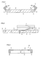
- FIG. 36 is a front view illustrating a main body 10M and an installation cover 20M used in illumination device 200 according to the present embodiment.
- Fig. 37 is a cross sectional view taken along a line XXXVII-XXXVII in Fig. 36 .
- Fig. 38 is a front view illustrating illumination device 200 in an assembled state (a state in which illumination panel 30 is installed between main body 10M and installation cover 20M).
- Fig. 39 is a cross sectional view taken along a line XXXIX-XXXIX in Fig. 38 .
- main body 10M is formed into a substantially triangular prism shape having two ends 11 (first end) and 12 (second end) facing each other.
- Main body 10M can be fixed on ceiling 50 and a side wall 51 through the intermediary of its rear face.
- Main body 10M is made of, for example, aluminum or stainless steel.
- Mounting face 15 of main body 10M is formed into an arc shape curving inward from end 11 toward end 12.
- a pair of electrical contacts 41 (first electrical contact) are disposed at predetermined positions on mounting face 15. Electrical contacts 41 are positioned in such a way that they can have a contact with electrical contacts (not shown) (corresponding to electrical contacts 42 in the above Embodiment 1) of illumination panel 30 when illumination panel 30 (see Figs. 38 and 39 ) is installed on main body 10M. As illustrated in Fig. 18 of the above Embodiment 1, the electrical contacts of illumination panel 30 may be disposed on the rear face of illumination panel 30 by extending with a predetermined length along the peripheral edges thereof. Since the electrical contacts of illumination panel 30 are sufficiently long relative to electrical contacts 41 on mounting face 15, even in the case where illumination panel 30 is fixed with a deviation to some extent, it is possible to obtain a good electrical connection between the electrical contacts of illumination panel 30 and electrical contacts 41.
- Electrical contacts 41 may be fixed on mounting face 15 with a portion thereof protruding therefrom like a plate spring. Thus, when illumination panel 30 is installed on main body 10M, a good electrical connection is achieved between the electrical contacts of illumination panel 30 and electrical contacts 41 of main body 10M. Electrical contacts 41 penetrate through main body 10M and are connected to a predetermined power source (not shown). End 11 is disposed with a plurality of supporting units 28 side by side, and end 12 is disposed with a plurality of supporting units 29 side by side at positions facing supporting units 28, respectively.
- Installation cover 20M is made of a transparent and elastically deformable material such as transparent acryl resin or polycarbonate having a rectangular shape, and is disposed across each facing pair of supporting units 28 and 29 like a bridge. Installation cover 20M is rotatably supported by supporting unit 28 and also by supporting unit 29.
- the thickness of installation cover 20M is, for example, 2 mm to 3 mm.
- the length of installation cover 20M in the longitudinal direction is longer than the direct distance between supporting unit 28 and supporting unit 29.
- the length of installation cover 20M in the longitudinal direction is roughly equal to the arc length of mounting face 15 in the same direction.
- a rear face of installation cover 20M defines pressing region 25 (see Fig. 37 ).
- illumination panel 30 is constructed in a similar manner to the above Embodiment 1.
- illumination panel 30 is inserted between installation cover 20M and mounting face 15 from a transverse direction. Thereafter, installation cover 20M is elastically deformed along mounting face 15 between end 11 and end 12 in the direction of an arrow AR5 (see Fig. 37 ).
- illumination device 200 illustrated in Figs. 38 and 39 is obtained.
- electrical power is supplied to light emitting face 33 of illumination panel 30 from an external power source (not shown) through the intermediary of electrical contacts 41 (see Fig. 36 ) disposed on main body 10M and the electrical contacts (not shown) disposed on illumination panel 30.
- electrical contacts 41 see Fig. 36
- light emitting face 33 emits light, which makes illumination device 200 ready for illumination.
- a plurality of installation covers 20M disposed across each facing pair of supporting units 28 and 29 like a bridge are separated from each other by a predetermined distance, and are configured to retain light emitting face 33 by pressing the corresponding portions on light emitting face 33 against mounting face 15 of main body 10M; however, the width, the number, the disposing positions, the shape and the like of installation covers 20M relative to light emitting face 33 may be appropriately defined in such a range capable of pressing light emitting face 33 so as to maintain the shape thereof.
- installation cover 20M may be formed into one piece as illustrated in Fig. 1 of the above Embodiment 1 so as to press the entire part of light emitting face 33, or may be formed into a lattice pattern as illustrated in Fig. 11 of the first modification of the above
- the sheet-shaped illumination panel 30 may bend in the direction of gravity due to the weight (dead weight) of illumination panel 30 itself.
- illumination device 200 in the present embodiment light emitting face 33 of illumination panel 30 is being pressed against mounting face 15 by pressing region 25 of installation cover 20M.
- pressing region 25 and mounting face 15 are being sandwiched by pressing region 25 and mounting face 15, and thereby the shape thereof is maintained.
- light emitting face 33 Due to the pressing by pressing region 25, light emitting face 33 will not bend, and thus, it is possible for it to maintain the initially designed shape. Thereby, it is possible for light emitting face 33 to achieve the initially designed light distribution characteristics without causing the problem that the intensity of light from light emitting face 33 may become irregular (uneven) depending on the direction of illumination.
- illumination panel 30 is fixed through the way of being sandwiched by main body 10M and installation cover 20M. Even in the case where illumination panel 30 is manufactured in dimensions different from the initially designed dimensions in, for example, the longitudinal direction, since illumination panel 30 is being fixed against main body 10M and installation cover 20M according to the pressing from both the obverse face and the rear face, no crinkles will occur.
- a warp may occur in illumination panel 30 due to the residual stress or the like resulting from the manufacture. Even in this situation, when illumination device 200 is in the assembled state, illumination panel 30 will be pressed by pressing region 25 and mounting face 15 to have the warp corrected.
- Light emitting face 33 is shaped (corrected) in correspondence with the shapes of mounting face 15 and pressing region 25. As a result, it is possible to keep light emitting face 33 in the initially designed shape, making it possible to achieve desired light distribution characteristics.
- FIG. 40 is a front view illustrating illumination device 201.
- Fig. 41 is a cross sectional view taken along a line XLI-XLI in Fig. 40 .
- illumination device 201 only one end of an installation cover 20N is fixed at supporting unit 28 permanently, and a part of installation cover 20N (i.e., the other end of installation cover 20N) is detachable from supporting unit 29A. As illustrated by an arrow AR6 (see Fig. 41 ), the other end of installation cover 20N can be detachably embedded into a recess 29K disposed in supporting unit 29A.
- illumination panel 30 In installing or replacing illumination panel 30, the other end of installation cover 20N is detached from supporting unit 29A. Since only one end of installation cover 20N is fixed at main body 10 (supporting unit 28), installation cover 20N hangs from supporting unit 28 (see dotted lines in Fig. 41 ). In this state, illumination panel 30 can be installed from the front side relative to mounting face 15.
- illumination panel 30 in the present modification may not be necessarily inserted from a traverse direction relative to mounting face 15. According to illumination device 201, it is possible to improve the working convenience of a worker in installing or replacing illumination panel 30.
Abstract
Description
- The present invention relates to an illumination device, and in particular relates to an illumination device provided with a sheet-shaped illumination panel.
- In recent years, in place of a point light emitting illumination device such as an incandescent bulb or a LED (Light Emitting Diode), a surface light emitting illumination device having an illumination panel is drawing attention. Japanese Patent Laid-Open No.
2004-055535 - In the illumination device of Japanese Patent Laid-Open No.
2004-055535 -
- PTD 1: Japanese Patent Laid-Open No.
2004-055535 - In the illumination device of Japanese Patent Laid-Open No.
2004-055535 PTD 1, the intensity of light from the illumination panel may be irregular depending on the direction of illumination. - An object of the present invention is to provide an illumination device including a sheet-shaped illumination panel and capable of achieving desired light distribution characteristics of the illumination panel.
- The illumination device according to the present invention includes a sheet-shaped, flexible illumination panel including on its surface a light emitting face, the light emitting face being configured to emit light when supplied with electrical power; a main body including a mounting face whereon the illumination panel is to be mounted; and an installation cover which to be installed on the main body and including a pressing region pressing the light emitting face of the illumination panel against the mounting face of the main body.
- According to the present invention, it is possible to obtain the illumination device including a sheet-shaped illumination panel and capable of achieving desired light distribution characteristics of the illumination panel.
-
-
Fig. 1 is a perspective view illustrating an illumination device according toEmbodiment 1 in an exploded state; -
Fig. 2 is a cross sectional view taken along a line II-II inFig. 1 ; -
Fig. 3 is a cross sectional view taken along a line III-III inFig. 1 ; -
Fig. 4 is a cross sectional view taken along a line IV-IV inFig. 1 ; -
Fig. 5 is a top view of an illumination panel used in the illumination device according toEmbodiment 1; -
Fig. 6 is a bottom view of the illumination panel used in the illumination device according toEmbodiment 1; -
Fig. 7 is a perspective view illustrating the illumination device according toEmbodiment 1 in an assembled state; -
Fig. 8 is a cross sectional view illustrating a modification of a retaining member used in the illumination device according toEmbodiment 1; -
Fig. 9 is a cross sectional view illustrating the illumination device according toEmbodiment 1 before being installed on a ceiling; -
Fig. 10 is a cross sectional view illustrating the illumination device according toEmbodiment 1 after being installed on the ceiling; -
Fig. 11 is a perspective view illustrating an installation cover used in an illumination device according to a first modification ofEmbodiment 1; -
Fig. 12 is a plan view illustrating an installation cover used in an illumination device according to a second modification ofEmbodiment 1; -
Fig. 13 is a cross sectional view illustrating an illumination device according to a third modification ofEmbodiment 1; -
Fig. 14 is a side view illustrating another configuration of the illumination device (before an installation cover is installed on a main body) according to the third modification ofEmbodiment 1; -
Fig. 15 is a side view illustrating another configuration of the illumination device (after the installation cover is installed on the main body) according to the third modification ofEmbodiment 1; -
Fig. 16 is a side view illustrating still another configuration of the illumination device (after the installation cover is installed on the main body) according to the third modification ofEmbodiment 1; -
Fig. 17 is a side view illustrating still another configuration of the illumination device (before the installation cover is installed on the main body) according to the third modification ofEmbodiment 1; -
Fig. 18 is a bottom view of an illumination panel used in an illumination device according to a fourth modification ofEmbodiment 1; -
Fig. 19 is a bottom view of an illumination panel used in an illumination device according to a fifth modification ofEmbodiment 1; -
Fig. 20 is a bottom view illustrating an installation cover used in an illumination device according to a sixth modification ofEmbodiment 1; -
Fig. 21 is a cross sectional view taken along a line XXI-XXI inFig. 20 ; -
Fig. 22 is a bottom view illustrating a state where the illumination panel is mounted on a pressing region of the installation cover used in the illumination device according to the sixth modification ofEmbodiment 1; -
Fig. 23 is a cross sectional view taken along a line XXIII-XXIII inFig. 22 ; -
Fig. 24 is a bottom view illustrating an installation cover used in an illumination device according to a seventh modification ofEmbodiment 1; -
Fig. 25 is a cross sectional view taken along a line XXV-XXV inFig. 24 ; -
Fig. 26 is a bottom view illustrating a state where the illumination panel is mounted on a pressing region of the installation cover used in the illumination device according to the seventh modification ofEmbodiment 1; -
Fig. 27 is a cross sectional view taken along a line XXVII-XXVII inFig. 26 ; -
Fig. 28 is a cross sectional view illustrating another configuration of the installation cover (prefixing portion) used in the illumination device according to the seventh modification ofEmbodiment 1; -
Fig. 29 is a bottom view illustrating an installation cover used in an illumination device according to an eighth modification ofEmbodiment 1; -
Fig. 30 is a perspective view illustrating a portion nearby a guide member of an installation cover used in the illumination device according to the eighth modification ofEmbodiment 1; -
Fig. 31 is a bottom view illustrating an illumination panel used in the illumination device according to the eighth modification ofEmbodiment 1; -
Fig. 32 is a bottom view illustrating an installation cover used in an illumination device according to a ninth modification ofEmbodiment 1; -
Fig. 33 is a bottom view illustrating an illumination panel used in the illumination device according to the ninth modification ofEmbodiment 1; -
Fig. 34 is a bottom view illustrating an installation cover used in an illumination device according to a tenth modification ofEmbodiment 1; -
Fig. 35 is a bottom view illustrating an illumination panel used in the illumination device according to the tenth modification ofEmbodiment 1; -
Fig. 36 is a front view illustrating a main body and an installation cover used in an illumination device according to Embodiment 2; -
Fig. 37 is a cross sectional view taken along a line XXXVII-XXXVII inFig. 36 ; -
Fig. 38 is a front view illustrating the illumination device according to Embodiment 2 in an assembled state; -
Fig. 39 is a cross sectional view taken along a line XXXIX-XXXIX inFig. 38 ; -
Fig. 40 is a front view illustrating an illumination device according to a modification of Embodiment 2; and -
Fig. 41 is a cross sectional view taken along a line XLI-XLI inFig. 40 . - Each embodiment of the present invention will be described hereinafter with reference to the drawings. In the description of each embodiment, unless otherwise specified, the scope of the present invention is not necessarily limited to the numbers or amounts indicated in each embodiment. In the description of each embodiment, the same or corresponding components are given the same reference numbers and may not be described repeatedly. Unless otherwise specified, an appropriate combination of configurations illustrated respectively in the embodiments has been initially expected.
-
Fig. 1 is a perspective view illustrating anillumination device 100 according to the present embodiment in an exploded state (prior to assembly).Illumination device 100 includes amain body 10, aninstallation cover 20 and anillumination panel 30. As illustrated by an arrow AR1,installation cover 20 is installed onmain body 10, sandwiching bothmain body 10 and illumination panel 30 (the details will be given later). -
Fig. 2 is a cross sectional view taken along a line II-II inFig. 1 , andFig. 3 is a cross sectional view taken along a line III-III inFig. 1 . As illustrated inFigs. 1 to 3 ,main body 10 is formed into a plate shape, and includes ends 11 to 14 and a mountingface 15.Main body 10 can be fixed on a ceiling (not shown), a wall surface (not shown) or the like through the intermediary of a rear face (opposite to mounting face 15).Main body 10 is made of, for example, aluminum or stainless steel through a pressing operation or a cutting operation. The thickness ofmain body 10 is, for example, from 2 cm to 10 cm. -
Main body 10 is disposed with an annular groove 16 (seeFigs. 1 to 3 ) having a predetermined depth along a peripheral edge of mountingface 15. To be described in detail hereinafter, the shape ofannular groove 16 fits with the shape of an embedding portion 23 (seeFigs. 1 and4 ) disposed oninstallation cover 20. Whenillumination device 100 is in the assembled state, embeddingportion 23 ofinstallation cover 20 is embedded inannular groove 16 ofmain body 10. - As illustrated in
Figs. 1 and3 , twocutouts 19 are carved side by side at predetermined positions on mountingface 15. A pair of electrical contacts 41 (first electrical contact) are disposed insidecutouts 19, respectively.Electrical contacts 41 are positioned in such a way that they can have a contact with electrical contacts 42 (seeFig. 6 ) ofillumination panel 30 whenillumination panel 30 is installed onmain body 10. - As illustrated in
Fig. 3 ,electrical contacts 41 disposed insidecutouts 19 may be fixed therein with a portion thereof protruding out of mountingface 15 like a plate spring. According to this configuration, whenillumination panel 30 is installed onmain body 10, a good electrical connection is achieved between electrical contacts 42 (seeFig. 6 ) ofillumination panel 30 andelectrical contacts 41 ofmain body 10.Electrical contacts 41 penetrate through main body 10 (seeFig. 3 ), and are connected to a predetermined power source (not shown). - As illustrated in
Figs. 1 and2 , two supportingunits 18 are disposed side by side atend 11 and end 12 facing each other, respectively. An L-shaped retainingmember 17 is rotatably installed at supportingunit 18. A biasing unit such as a coil spring or the like is built inside supportingunit 18. Due to the action from the biasing unit such as a coil spring or the like, retainingmember 17 installed at supportingunit 18 is biased to rotate toward mountingface 15 in the direction of an arrow AR2 (seeFig. 2 ). -
Fig. 4 is a cross sectional view taken along a line IV-IV inFig. 1 . As illustrated inFigs. 1 and4 ,installation cover 20 includes aplate member 21 and embeddingportion 23. Embeddingportion 23 is erected circularly around the outer periphery ofplate member 21. As mentioned in the above, the shape of embeddingportion 23 fits with the shape of annular groove 16 (seeFig. 1 ) disposed onmain body 10. - The inner peripheral side of
plate member 21 is disposed with a rectangular transparent plate 22 (transparent region) made of glass, acryl resin or the like. The thickness oftransparent plate 22 is, for example, from 2 mm to 3 mm. The rear face (where embeddingportion 23 is erected) oftransparent plate 22 defines apressing region 25. The surface shape of pressing region 25 (the shape of the rear face of transparent plate 22) fits with the surface shape of mountingface 15. Whenillumination device 10 is in an assembled state, pressingregion 25 presses the entire part of alight emitting face 33 ofillumination panel 30 against mountingface 15 ofmain body 10. -
Fig. 5 is a top view ofillumination panel 30, andFig. 6 is a bottom view ofillumination panel 30.Illumination panel 30 is formed into a shape of a flexible sheet (seeFigs. 1 ,5 and 6 ). The thickness ofillumination panel 30 is, for example, about 1 mm. Here, a sheet represents a planar sheet having a thickness from about 0.5 mm to about 10 mm, preferably having a substantially uniform thickness from about 0.5 mm to about 1 mm, and also includes such a sheet of a thickness as those referred to as a film sheet or a thin-plate sheet. - The rectangular
light emitting face 33 which emits light when supplied with electrical power is formed on anobverse face 31 ofillumination panel 30.Light emitting face 33 may be constructed from, for example, organic EL (OLED: Organic Light Emitting Diode) elements. Arear face 32 ofillumination panel 30 is disposed with a pair of electrical contacts 42 (second electrical contact) for supplying electrical power to light emittingface 33. - In the case where light emitting
face 33 is constructed from organic EL elements, electrical power is supplied to both sides of an organic light emitting layer insidelight emitting face 33. When supplied with electrical power, the organic light emitting layer emits visible light. A transparent electrode layer (such as ITO) is disposed on the organic light emitting layer at the side of light emitting face 33 (the side of obverse face 31), and the transparent electrode layer is sealed by a sealing layer. An electrode layer, for example an aluminum electrode layer configured to reflect the emitted light, is disposed underneath the organic light emitting layer (at the side of rear face 32). Underneath the electrode layer (the side of rear face 32), a base layer is disposed. The electrode layers on both sides of the organic light emitting layer are wired, according to a predetermined pattern, to the pair ofelectrical contacts 42 disposed onrear face 32, respectively. -
Fig. 7 is a perspective view illustratingillumination device 100 in an assembled state (after being assembled). In assemblingillumination device 100,main body 10 and installation cover 20 are arranged opposite to each other, sandwichingillumination panel 30 therebetween (seeFigs. 1 and7 ). Retainingmember 17 ofmain body 10 is rotated in the direction opposite to arrow AR2 (seeFig. 2 ) so as to be erected. Retainingmember 17 may be kept at an erected state against the biasing force of a coil spring or the like through hooking by using, for example, a latch mechanism (not shown). - Then, embedding
portion 23 ofinstallation cover 20 is embedded intoannular groove 16 ofmain body 10. Thus,illumination panel 30 is sandwiched by transparent plate 22 (pressing region 25) ofinstallation cover 20 and mountingface 15 ofmain body 10. Thereafter, the hooking by the latch mechanism is released according to the operation of a release lever or a release button (not shown). Accordingly, the erected state of retainingmember 17, which is kept by the latch mechanism through hooking, is also released. Thereby, retainingmember 17 is biased by a coil spring or the like to rotate in the direction of arrow AR2 (seeFig. 2 ). Retainingmember 17 pressesplate member 21 ofinstallation cover 20 toward mountingface 15. - Due to the pressing from retaining
member 17,installation cover 20 andillumination panel 30 are installed onmain body 10. Pressing region 25 (seeFigs. 1 and4 ) presseslight emitting face 33 toward mountingface 15. According the abovementioned procedure,illumination device 100 as illustrated inFig. 7 is obtained. Inillumination device 100, electrical power is supplied to light emittingface 33 ofillumination panel 30 from an external power source (not shown) through the intermediary of electrical contacts 41 (seeFig. 1 ) disposed onmain body 10 and electrical contacts 42 (seeFig. 6 ) disposed onillumination panel 30. When supplied with the electrical power,light emitting face 33 emits light, which makesillumination device 100 ready for illumination. - According to the approach described above with reference to
Fig. 2 and the like, in installingillumination panel 30 onmain body 10, retainingmember 17 is rotated in the direction opposite to arrow AR2. While retainingmember 17 is in the erected state according to the hooking by the latch mechanism,illumination panel 30 is installed onmain body 10. Thereafter, the hooking by the latch mechanism is released, andillumination panel 30 is fixed onmain body 10 by a biasing force in the direction of arrow AR2 by a coil spring or the like. However, the approach of installingillumination panel 30 onmain body 10 is not limited to that illustrated inFig. 2 and the like as mentioned in the above, and it is acceptable to adopt a configuration using a retainingmember 17A as illustrated inFig. 8 to do the same. - According to an approach as illustrated in
Fig. 8 , in installingillumination panel 30 and installation cover 20 onmain body 10, it is unnecessary to manually rotate retainingmembers 17A one by one in the direction opposite to arrow AR2. Specifically, atip end 17T of retainingmember 17A is made inclined so as to accept embeddingportion 23 ofinstallation cover 20. When pressinginstallation cover 20 andillumination panel 30 toward a predetermined installation position onmain body 10, embeddingportion 23 of installation cover 20 contacts tipend 17T of retainingmember 17A. - At this time, embedding
portion 23 ofinstallation cover 20pushes retaining member 17A toward the direction opposite to arrow AR2. Thereby, retainingmember 17A rotates in the direction opposite to arrow AR2 against the biasing force from acoil spring 17C. At a timing when embeddingportion 23 of installation cover 20 passes overtip end 17T of retainingmember 17A (the timing when embeddingportion 23 ofinstallation cover 20 loses the contact withtip end 17T of retainingmember 17A), retainingmember 17A restores in the direction of arrow AR2 due to the biasing force fromcoil spring 17C.Illumination panel 30 and installation cover 20 are pressed againstmain body 10 by an engagingsection 17K disposed in retainingmember 17A. According to the configuration illustrated inFig. 8 , it is possible to easily installillumination panel 30 and installation cover 20 onmain body 10. - As shown in
Fig. 1 , the sheet-shapedillumination panel 30 may bend in the direction of gravity due to initial distortions (such as a warp or the like resulting from manufacture or transportation) and/or due to the weight (dead weight) ofillumination panel 30 itself according to an installation manner thereof. According toillumination device 100 of the present embodiment,light emitting face 33 ofillumination panel 30 is pressed against mountingface 15 by pressingregion 25 ofinstallation cover 20. Thus,light emitting face 33 is being sandwiched by pressingregion 25 and mountingface 15, and thereby the shape thereof is retained. - In the illumination device of Japanese Patent Laid-Open No.
2004-055535 PTD 1 is in contact with the main body, and the other face thereof is not in contact with any members but exposed as the light emitting face (the so-called "single face-contacting installation structure"). When the illumination device inPTD 1 is installed on a ceiling, a wall surface or the like, the illumination panel may bend due to its dead weight. Since the illumination device inPTD 1 adopts the so-called single face-contacting installation structure, the bending of the illumination panel remains even after the installation. - Even when
illumination device 100 of the present embodiment is installed on the ceiling, the wall surface or the like, sincelight emitting face 33 is being pressed by pressingregion 25, it will not bend. Thereby, according to the configuration where the shape of pressingregion 25 ofinstallation cover 20 and the shape of mountingface 15 ofmain body 10 are formed fitting with the desired shape of light emittingface 33 andillumination panel 30 is sandwiched byinstallation cover 20 andlight emitting face 33, it is possible to keep light emittingface 33 at the initially designed shape. Thereby, it is possible forlight emitting face 33 to achieve the initially designed light distribution characteristics without causing the problem that the intensity of light fromlight emitting face 33 may become irregular (uneven) depending on the direction of illumination from light emittingface 33. - In the illumination device of
PTD 1, the retaining members for pre-installing the illumination panel on the main body (supporting body) are designed to have a predetermined distance therebetween. Correspondingly, both ends of the illumination panel each is disposed preliminarily with a clip or the like. However, due to manufacturing error or the like, the distance between the retaining members may not fit with the distance between the clips disposed at both ends of the illumination panel. In forming the illumination panel into the sheet shape, due to the characteristics of the illumination panel, such manufacturing error is easy to occur. In the case where the distance between the retaining members is different from the distance between the clips, such problem may occur that the illumination panel may have to be crinkled in order to be installed on the main body. - In
illumination device 100 of the present embodiment,illumination panel 30 is fixed through the way of being sandwiched bymain body 10 andinstallation cover 20. Even in the case whereillumination panel 30 is manufactured with dimensions different from the initially designed dimensions along, for example, the longitudinal direction, sinceillumination panel 30 is being fixed againstmain body 10 and installation cover 20 according to the pressing from both the obverse face and the rear face, no crinkles will occur. Even at this viewpoint, it is possible forillumination device 100 to achieve the desired light distribution characteristics. - With reference to
Figs. 9 and10 , the installation of illumination device 100 (seeFig. 10 ) onceiling 50 will be described. InFigs. 9 and10 , retainingmember 17 and supportingunit 18 are installed at positions deviated 90° from the positions illustrated inFig. 1 . In other words, the installation positions of retainingmember 17 and supportingunit 18 may be at the positions illustrated inFig. 1 (retainingmember 17 and supportingunit 18 are configured to be installed on ends 11 and 12) or may be at the positions illustrated inFigs. 9 and10 (retainingmember 17 and supportingunit 18 are configured to be installed on ends 13 and 14). - In the case of installing illumination device 100 (see
Fig. 10 ) onceiling 50, firstly,main body 10 is fixed onceiling 50 through bolts and nuts or the like. Thereafter,illumination panel 30 is mounted on pressingregion 25 ofinstallation cover 20, withlight emitting face 33 facing downward. Under this condition, as illustrated by an arrow AR3, embeddingportion 23 ofinstallation cover 20 is embedded intoannular groove 16 ofmain body 10. At this time, as illustrated inFig. 9 , a warp may occur in the sheet-shapedillumination panel 30 due to the residual stress or the like resulting from the manufacture. - According to
illumination device 100 of the present embodiment,illumination panel 30 is fixed through the way of being sandwiched bymain body 10 andinstallation cover 20. Even though a warp has occurred onillumination panel 30, whenillumination device 100 is in the assembled state,illumination panel 30 will be pressed by pressingregion 25 and mountingface 15 and thereby the warp will be corrected.Light emitting face 33 will be shaped (corrected) in correspondence with the shapes of mountingface 15 and pressing region 15 (transparent plate 22). As a result, it is possible to keep light emittingface 33 in the initially designed shape, making it possible to achieve desired light distribution characteristics. -
Fig. 11 is a perspective view illustrating aninstallation cover 20A used in an illumination device according to a first modification of theabove Embodiment 1. Ininstallation cover 20A of the present modification, a plurality of throughholes 22A may be disposed in an inner periphery ofplate member 21. Different from installation cover 20 of theabove Embodiment 1,installation cover 20A does not includetransparent plate 22. Each throughhole 22A is formed by perforatingplate member 21, and throughholes 22A are arranged in a lattice pattern, for example. -
Pressing region 25 is defined by the remaining part without being perforated on the rear face ofplate member 21. Thereby, pressingregion 25 of the present modification is formed into the lattice pattern defmed by the shape of each throughhole 22A. For the purpose of correcting a warp onillumination panel 30, it is desirable thatpressing region 25 is arranged uniformly relative to the entire part of light emittingface 33, like installation cover 20A having the lattice-patterned portion according to the present modification. On the other hand, pressingregion 25 may not have to be arranged uniformly relative to the entire part of light emittingface 33; it is acceptable thatpressing region 25 is formed somewhat non-uniformly as long as pressingregion 25 can press a part of light emittingface 33 so as to correct the warp onillumination panel 30 to some extent, and it is also acceptable thatpressing region 25 is formed into the other shapes from the viewpoint of design or the like. Afterinstallation cover 20A of the present modification is assembled into the illumination device, light emitting face 33 (seeFig. 1 ) of illumination panel 30 (seeFig. 1 ) is directly exposed out of throughholes 22A. - When a part of light emitting
face 33 is pressed by pressingregion 25 against mountingface 15 through the lattice pattern, it is possible forlight emitting face 33 to keep the initially designed shape. As a result, due to the contribution ofinstallation cover 20A, it is possible forlight emitting face 33 to achieve the initially designed light distribution characteristics without causing the problem that the intensity of light fromlight emitting face 33 may become irregular (uneven) depending on the direction of illumination. -
Fig. 12 is a plan view illustrating aninstallation cover 20B used in an illumination device according to a second modification of theabove Embodiment 1. Ininstallation cover 20B of the present modification,wires 22B are disposed in the inner periphery ofplate member 21. Different from installation cover 20 of theabove Embodiment 1,installation cover 20B does not includetransparent plate 22. In place oftransparent plate 22,wires 22B are disposed in a lattice pattern, for example, as illustrated inFig. 12 . -
Pressing region 25 is defined by a rear face ofwires 22B. Similarly to the disposition of throughholes 22A in the first modification of theabove Embodiment 1, pressing region 25 (wires 22B) may be formed into the other shapes from the viewpoint of design on a condition that it is possible for it to press a part of light emittingface 33. - After
installation cover 20B of the present modification is assembled into the illumination device, light emitting face 33 (seeFig. 1 ) of illumination panel 30 (seeFig. 1 ) is exposed directly through the spaces betweenwires 22B. When a part of light emittingface 33 is pressed by pressingregion 25 against mountingface 15 through the lattice pattern, it is possible forlight emitting face 33 to keep the initially designed shape. As a result, due to the contribution ofinstallation cover 20B, it is also possible forlight emitting face 33 to achieve the initially designed light distribution characteristics without causing the problem that the intensity of light fromlight emitting face 33 may become irregular (uneven) depending on the direction of illumination. -
Fig. 13 is a cross sectional view illustrating an illumination device according to a third modification of theabove Embodiment 1. Aninstallation cover 20C used in the illumination device according to the present modification has a part thereof (herein, one end ofinstallation cover 20C) preliminarily fixed atmain body 10 through the intermediary of a supportingunit 18A.Installation cover 20C is rotatable about supportingunit 18A. Embeddingportion 23 at the other end ofinstallation cover 20C can be embedded intoannular groove 16, as illustrated by an arrow AR4. - According to the illumination device of the present modification, preliminary (permanent) installation of
installation cover 20C onmain body 10 makes it possible to improve the working convenience of a worker in installing or replacingillumination panel 30. - In an installation cover 20C1 as illustrated in
Fig. 14 , arestraint member 24 may be disposed between installation cover 20C1 andmain body 10.Restraint member 24 is constructed by joining two thin plate members.Restraint member 24 may be a string-like member. As illustrated inFig. 14 ,restraint member 24 may be disposed along the side surfaces ofmain body 10 and installation cover 20C1.Restraint member 24 is configured to restrain installation cover 20C1 from being opened too wide frommain body 10 when installation cover 20C1 is rotated about supportingunit 18A. Due to the disposition ofrestraint member 24, the angle of installation cover 20C1 relative tomain body 10 can be kept at a predetermined value, which makes it possible to easily mountillumination panel 30 onto installation cover 20C1. - As illustrated in
Fig. 15 , when installation cover 20C1 is installed onmain body 10,restraint member 24 is folded along the side surfaces ofmain body 10 and installation cover 20C1. By disposingrestraint member 24 at the side surfaces ofmain body 10 and installation cover 20C1, it is possible to preventrestraint member 24 from interrupting the installing work or replacing work ofillumination panel 30, which further improves the working convenience. - In an installation cover 20C2 as illustrated in
Fig 16 , arestraint member 24A may be disposed as a unit for restraining installation cover 20C2 from being opened too wide frommain body 10.Restraint member 24A is disposed at the end of installation cover 20C2 where installation cover 20C2 is installed on supportingunit 18A. As illustrated inFig 17 , as installation cover 20C2 is rotated about supportingunit 18A,restraint member 24A contacts ceiling 50, which thereby restrains installation cover 20C2 from being opened too wide frommain body 10. According to this configuration, it is also possible to obtain the same effects as the abovementioned restraint member 24 (seeFigs. 14 and 15 ). -
Fig. 18 is a bottom view of anillumination panel 30A used in an illumination device according to a fourth modification of theabove Embodiment 1.Fig. 18 corresponds toFig. 6 in theabove Embodiment 1. Inillumination panel 30A of the present modification, a pair ofelectrical contacts 42 are disposed onrear face 32 ofillumination panel 30 by extending with a predetermined length along the peripheral edges thereof. - Meanwhile, electrical contacts 41 (not shown) disposed on main body 10 (not shown) are arranged at predetermined positions on mounting face 15 (not shown) in accordance with the positions of
electrical contacts 42. Sinceelectrical contacts 42 are sufficiently long relative toelectrical contacts 41 on mountingface 15, even in the case whereillumination panel 30A is fixed with a deviation to some extent, it is possible to obtain a good electrical connection betweenelectrical contacts 41 andelectrical contacts 42. -
Fig. 19 is a bottom view of anillumination panel 30B used in an illumination device according to a fifth modification of theabove Embodiment 1.Fig. 19 corresponds toFig. 6 in theabove Embodiment 1. Inillumination panel 30B of the present modification, a pair of positive electrical contacts 42 (42A) are disposed onrear face 32 ofillumination panel 30B by extending with a predetermined length along the opposing peripheral edges thereof. - Similarly, a pair of negative electrical contacts 42 (42B) are disposed on
rear face 32 ofillumination panel 30B by extending with a predetermined length along the other opposing peripheral edges thereof. It is acceptable thatillumination panel 30B has two positive electrical contacts 42 (42A) and two negative electrical contacts 42 (42B) disposed onrear face 32. - Similarly to the arrangement of
electrical contacts 41 on mountingface 15 at predetermined positions in correspondence with the positions ofelectrical contacts 42 as in the fourth modification of theabove Embodiment 1, in the fifth modification, electrical contacts 41 (not shown) disposed on main body 10 (not shown) are arranged at predetermined positions on mounting face 15 (not shown) in respective accordance with the positions of positive electrical contacts 42 (42A) and the position of negative electrical contacts 42 (42B). Since positive electrical contacts 42 (42A) and negative electrical contacts 42 (42B) are sufficiently long relative toelectrical contacts 41 on mountingface 15, even in the case whereillumination panel 30A is fixed with a deviation to some extent, it is possible to obtain a good electrical connection fromelectrical contacts 41 to electrical contacts 42 (42A) and to electrical contacts 42 (42B). - With reference to
Figs. 20 to 23 , an illumination device according to a sixth modification of theabove Embodiment 1 will be described.Fig. 20 is a bottom view illustrating aninstallation cover 20D used in the illumination device according to the present modification.Fig. 21 is a cross sectional view taken along a line XXI-XXI inFig. 20. Fig. 22 is a bottom view illustrating a state whereillumination panel 30 is mounted on pressingregion 25 ofinstallation cover 20D.Fig. 23 is a cross sectional view taken along a line XXIII-XXIII inFig. 22 . - As illustrated in
Figs. 20 and 21 , prefixingportions 26 are disposed at a peripheral edge (herein, the top end of embeddingportion 23 in the erecting direction) ofinstallation cover 20D. Prefixingportions 26 ofinstallation cover 20D are disposed side by side on one end of the annular-shaped embeddingportion 23 in rectangular form, extending with a predetermined length so as to have a partial overlap with pressingregion 25 in planar view. Each prefixingportion 26 is separated from pressingregion 25 by a distance L1 (seeFig. 21 ). It should be noted that along with the disposition of prefixingportion 26, the shape of annular groove 16 (not shown) disposed in mounting face 15 (not shown) of main body 10 (not shown) may be changed in accordance with the shape of prefixingportion 26. - As illustrated in
Figs. 22 and23 , in mountingillumination panel 30 on pressingregion 25 ofinstallation cover 20D, each end portion (having a thickness L2) ofillumination panel 30 is inserted between prefixingportions 26 and pressing region 25 (thickness L2 < distance L1). Thereby,illumination panel 30 is prefixed relative toinstallation cover 20D. Due to the prefixing,illumination panel 30 is prevented from dropping (being disengaged) away frominstallation cover 20D, which makes it possible to improve the working convenience of a worker in installing or replacingillumination panel 30. - With reference to
Figs. 24 to 27 , an illumination device according to a seventh modification of theabove Embodiment 1 will be described.Fig. 24 is a bottom view illustrating aninstallation cover 20E used in the illumination device according to the present modification.Fig. 25 is a cross sectional view taken along a line XXV-XXV inFig. 24 .Fig. 26 is a bottom view illustrating a state whereillumination panel 30 is mounted on pressingregion 25 ofinstallation cover 20E.Fig. 27 is a cross sectional view taken along a line XXVII-XXVII inFig. 26 . - As illustrated in
Figs. 24 and 25 , prefixingportions 26 are disposed at peripheral edges (herein, the top ends of embeddingportion 23 in the erecting direction) ofinstallation cover 20E. Two prefixingportions 26 ofinstallation cover 20E are disposed side by side on each of two opposing ends of the annular-shaped embeddingportion 23 in rectangular form, extending with a predetermined length so as to have a partial overlap with pressingregion 25 in planar view. Each prefixingportion 26 is separated from pressingregion 25 by distance L1 (seeFig. 25 ). It should be noted that along with the disposition of prefixingportion 26, the shape of annular groove 16 (not shown) disposed on mounting face 15 (not shown) of main body 10 (not shown) may be changed in accordance with the shape of prefixingportion 26. - As illustrated in
Figs. 26 and 27 , in mountingillumination panel 30 on pressingregion 25 ofinstallation cover 20E, each end portion (having thickness L2) ofillumination panel 30 is inserted between prefixingportions 26 and pressing region 25 (thickness L2 < distance L1). Similarly toinstallation cover 20D of the sixth modification (seeFigs. 20 to 23 ) in the above,illumination panel 30 is prefixed relative toinstallation cover 20E. Due to the prefixing,illumination panel 30 is prevented from dropping (being disengaged) away frominstallation cover 20E, which makes it possible to improve the working convenience of a worker in installing or replacingillumination panel 30. - As illustrated in
Fig. 28 , prefixingportion 26 may be configured as being rotatable in the direction of an arrow inFig. 28 about the top end of embeddingportion 23 in the erecting direction towardillumination panel 30. In mountingillumination panel 30 on the installation cover (installation cover 20E), by erecting prefixing portions 26 (to the state illustrated inFig. 28 ), it is possible to easily mountillumination panel 30 on the installation cover (installation cover 20E). Afterillumination panel 30 is mounted,illumination panel 30 is prefixed by rotating prefixingportion 26 towardillumination panel 30. Similarly, in the sixth modification (seeFigs. 20 to 23 ) described in the above, prefixingportion 26 may be configured as being rotatable about the top end of embeddingportion 23 in the erecting direction towardillumination panel 30. - With reference to
Figs. 29 to 31 , an illumination device according to an eighth modification of theabove Embodiment 1 will be described.Fig. 29 is a bottom view illustrating aninstallation cover 20F used in the illumination device according to the present modification.Fig. 30 is a perspective view illustrating a portion nearby a guide member 27 (the detail thereof will be described hereinafter) ofinstallation cover 20F.Fig. 31 is a bottom view illustrating anillumination panel 30C used in the illumination device according to the present modification. - As illustrated in
Figs. 29 and 30 , guide member 27 (first guide portion) is formed at a peripheral edge (herein, a corner of the annular-shaped embeddingportion 23 in rectangular form) ofinstallation cover 20F.Guide member 27 is formed into a substantially triangular prism shape by extending from the top end of embeddingportion 23 in the erecting direction to reach plate member 21 (in the direction orthogonal to the plane of paper inFig. 29 ) and bulging from the corner of embeddingportion 23 toward pressingregion 25. - As illustrated in
Fig. 31 , a guide member 37 (first guide portion) is formed at a peripheral edge (herein, a corner ofillumination panel 30C in rectangular form) ofillumination panel 30C.Guide member 37 is formed by chamfering the corner.Guide member 37 fits withguide member 27 ofinstallation cover 20F in shape and position. - In assembling the illumination device according to the present modification,
illumination panel 30C is mounted on pressingregion 25 ofinstallation cover 20F in such a way that guidemember 27 and guidemember 37 fit each other (i.e., face each other).Illumination panel 30C cannot be mounted on pressingregion 25 ofinstallation cover 20F from another geometric angle (phase). Thereby, the so-called reverse insertion ofillumination panel 30C intoinstallation cover 20F is prevented, which in turn prevents electrical contacts 41 (not shown) on main body 10 (not shown) from being connected toelectrical contacts 42 onillumination panel 30C in wrong polarity, making it possible to improve the working convenience of a worker in installing or replacingillumination panel 30C. - With reference to
Figs. 32 and 33 , an illumination device according to a ninth modification of theabove Embodiment 1 will be described.Fig. 32 is a bottom view illustrating aninstallation cover 20G used in the illumination device according to the present modification.Fig. 33 is a bottom view illustrating anillumination panel 30D used in the illumination device according to the present modification. - As illustrated in
Fig. 32 , guide member 27 (second guide portion) is formed at a peripheral edge (herein, one end of the annular-shaped embeddingportion 23 in rectangular form) ofinstallation cover 20G.Guide member 27 is formed into a cuboid shape by extending from the top end of embeddingportion 23 in the erecting direction to reach plate member 21 (in the direction orthogonal to the plane of paper inFig. 32 ) and bulging from one end of embeddingportion 23 toward pressingregion 25. - As illustrated in
Fig. 33 , guide member 37 (first guide member) is formed at a peripheral edge (herein, one end ofillumination panel 30D in rectangular form) ofillumination panel 30D.Guide member 37 is formed by cutting out a part of the edge, fitting withguide member 27 ofinstallation cover 20G in shape and position. - In assembling the illumination device according to the present modification, similarly to the eighth modification (see
Figs. 29 to 31 ) in the above,illumination panel 30D is mounted on pressingregion 25 ofinstallation cover 20G in such a way that guidemember 27 and guidemember 37 fit each other (i.e., face each other).Illumination panel 30D cannot be mounted on pressingregion 25 ofinstallation cover 20G from another geometric angle (phase). Thereby, the so-called reverse insertion ofillumination panel 30D intoinstallation cover 20G is prevented, which in turn prevents electrical contacts 41 (not shown) on main body 10 (not shown) from being connected toelectrical contacts 42 onillumination panel 30D in wrong polarity, making it possible to improve the working convenience of a worker in installing or replacingillumination panel 30D. - With reference to
Figs. 34 and 35 , an illumination device according to a tenth modification of theabove Embodiment 1 will be described.Fig. 34 is a bottom view illustrating aninstallation cover 20H used in the illumination device according to the present modification.Fig. 35 is a bottom view illustrating anillumination panel 30E used in the illumination device according to the present modification. - As illustrated in
Fig. 34 , guide member 27 (first guide portion) is formed at a peripheral edge (herein, one end of the annular-shaped embeddingportion 23 in rectangular form) ofinstallation cover 20H.Guide member 27 is formed into a cuboid shape by extending from the top end of embeddingportion 23 in the erecting direction to reach plate member 21 (in the direction orthogonal to the plane of paper inFig. 34 ) and being cut away from one end of embeddingportion 23 toward the opposite side of pressingregion 25. - As illustrated in
Fig. 35 , guide member 37 (second guide portion) is formed at a peripheral edge (herein, one end ofillumination panel 30E in rectangular form) ofillumination panel 30E.Guide member 37 is formed by bulging from the end, fitting withguide member 27 ofinstallation cover 20H in shape and position. - In assembling the illumination device according to the present modification, similarly to the eighth modification (see
Figs. 29 to 31 ) and the ninth modification (seeFigs. 32 and 33 ) in the above,illumination panel 30E is mounted on pressingregion 25 ofinstallation cover 20H in such a way that guidemember 27 and guidemember 37 fit each other (i.e., face each other).Illumination panel 30E cannot be mounted on pressingregion 25 ofinstallation cover 20H from another geometric angle (phase). Thereby, the so-called reverse insertion ofillumination panel 30E intoinstallation cover 20H is prevented, which in turn prevents electrical contacts 41 (not shown) on main body 10 (not shown) from being connected toelectrical contacts 42 onillumination panel 30E in wrong polarity, making it possible to improve the working convenience of a worker in installing or replacingillumination panel 30E. - With reference to
Figs. 36 to 39 , an illumination device 200 (seeFigs. 38 and 39 ) according to the present embodiment will be described.Fig. 36 is a front view illustrating amain body 10M and aninstallation cover 20M used inillumination device 200 according to the present embodiment.Fig. 37 is a cross sectional view taken along a line XXXVII-XXXVII inFig. 36 .Fig. 38 is a front view illustratingillumination device 200 in an assembled state (a state in whichillumination panel 30 is installed betweenmain body 10M andinstallation cover 20M).Fig. 39 is a cross sectional view taken along a line XXXIX-XXXIX inFig. 38 . - As illustrated in
Figs. 36 and 37 ,main body 10M is formed into a substantially triangular prism shape having two ends 11 (first end) and 12 (second end) facing each other.Main body 10M can be fixed onceiling 50 and aside wall 51 through the intermediary of its rear face.Main body 10M is made of, for example, aluminum or stainless steel. - Mounting
face 15 ofmain body 10M is formed into an arc shape curving inward fromend 11 towardend 12. A pair of electrical contacts 41 (first electrical contact) are disposed at predetermined positions on mountingface 15.Electrical contacts 41 are positioned in such a way that they can have a contact with electrical contacts (not shown) (corresponding toelectrical contacts 42 in the above Embodiment 1) ofillumination panel 30 when illumination panel 30 (seeFigs. 38 and 39 ) is installed onmain body 10M. As illustrated inFig. 18 of theabove Embodiment 1, the electrical contacts ofillumination panel 30 may be disposed on the rear face ofillumination panel 30 by extending with a predetermined length along the peripheral edges thereof. Since the electrical contacts ofillumination panel 30 are sufficiently long relative toelectrical contacts 41 on mountingface 15, even in the case whereillumination panel 30 is fixed with a deviation to some extent, it is possible to obtain a good electrical connection between the electrical contacts ofillumination panel 30 andelectrical contacts 41. -
Electrical contacts 41 may be fixed on mountingface 15 with a portion thereof protruding therefrom like a plate spring. Thus, whenillumination panel 30 is installed onmain body 10M, a good electrical connection is achieved between the electrical contacts ofillumination panel 30 andelectrical contacts 41 ofmain body 10M.Electrical contacts 41 penetrate throughmain body 10M and are connected to a predetermined power source (not shown).End 11 is disposed with a plurality of supportingunits 28 side by side, and end 12 is disposed with a plurality of supportingunits 29 side by side at positions facing supportingunits 28, respectively. -
Installation cover 20M is made of a transparent and elastically deformable material such as transparent acryl resin or polycarbonate having a rectangular shape, and is disposed across each facing pair of supportingunits Installation cover 20M is rotatably supported by supportingunit 28 and also by supportingunit 29. The thickness ofinstallation cover 20M is, for example, 2 mm to 3 mm. The length ofinstallation cover 20M in the longitudinal direction is longer than the direct distance between supportingunit 28 and supportingunit 29. The length ofinstallation cover 20M in the longitudinal direction is roughly equal to the arc length of mountingface 15 in the same direction. A rear face ofinstallation cover 20M defines pressing region 25 (seeFig. 37 ). - With reference to
Figs. 38 and 39 ,illumination panel 30 is constructed in a similar manner to theabove Embodiment 1. In assemblingillumination device 200, whileinstallation cover 20M and mountingface 15 are being separated from each other,illumination panel 30 is inserted betweeninstallation cover 20M and mountingface 15 from a transverse direction. Thereafter,installation cover 20M is elastically deformed along mountingface 15 betweenend 11 and end 12 in the direction of an arrow AR5 (seeFig. 37 ). - According to the elastic deformation, pressing
region 25 ofinstallation cover 20M presseslight emitting face 33 ofillumination panel 30 against mountingface 15 ofmain body 10M. According the abovementioned procedure,illumination device 200 illustrated inFigs. 38 and 39 is obtained. Inillumination device 200, electrical power is supplied to light emittingface 33 ofillumination panel 30 from an external power source (not shown) through the intermediary of electrical contacts 41 (seeFig. 36 ) disposed onmain body 10M and the electrical contacts (not shown) disposed onillumination panel 30. When supplied with the electrical power,light emitting face 33 emits light, which makesillumination device 200 ready for illumination. In the present embodiment, a plurality of installation covers 20M disposed across each facing pair of supportingunits face 33 by pressing the corresponding portions on light emittingface 33 against mountingface 15 ofmain body 10M; however, the width, the number, the disposing positions, the shape and the like of installation covers 20M relative to light emittingface 33 may be appropriately defined in such a range capable of pressinglight emitting face 33 so as to maintain the shape thereof. On a condition of not affecting manipulation performance,installation cover 20M may be formed into one piece as illustrated inFig. 1 of theabove Embodiment 1 so as to press the entire part of light emittingface 33, or may be formed into a lattice pattern as illustrated inFig. 11 of the first modification of the above - The sheet-shaped
illumination panel 30 may bend in the direction of gravity due to the weight (dead weight) ofillumination panel 30 itself. According toillumination device 200 in the present embodiment,light emitting face 33 ofillumination panel 30 is being pressed against mountingface 15 by pressingregion 25 ofinstallation cover 20M. Thus,light emitting face 33 is being sandwiched by pressingregion 25 and mountingface 15, and thereby the shape thereof is maintained. - Due to the pressing by pressing
region 25,light emitting face 33 will not bend, and thus, it is possible for it to maintain the initially designed shape. Thereby, it is possible forlight emitting face 33 to achieve the initially designed light distribution characteristics without causing the problem that the intensity of light fromlight emitting face 33 may become irregular (uneven) depending on the direction of illumination. - In
illumination device 200,illumination panel 30 is fixed through the way of being sandwiched bymain body 10M andinstallation cover 20M. Even in the case whereillumination panel 30 is manufactured in dimensions different from the initially designed dimensions in, for example, the longitudinal direction, sinceillumination panel 30 is being fixed againstmain body 10M andinstallation cover 20M according to the pressing from both the obverse face and the rear face, no crinkles will occur. - A warp may occur in
illumination panel 30 due to the residual stress or the like resulting from the manufacture. Even in this situation, whenillumination device 200 is in the assembled state,illumination panel 30 will be pressed by pressingregion 25 and mountingface 15 to have the warp corrected.Light emitting face 33 is shaped (corrected) in correspondence with the shapes of mountingface 15 andpressing region 25. As a result, it is possible to keep light emittingface 33 in the initially designed shape, making it possible to achieve desired light distribution characteristics. - With reference to
Figs. 40 and 41 , anillumination device 201 according to a modification of the above Embodiment 2 will be described.Fig. 40 is a front view illustratingillumination device 201.Fig. 41 is a cross sectional view taken along a line XLI-XLI inFig. 40 . - In
illumination device 201, only one end of aninstallation cover 20N is fixed at supportingunit 28 permanently, and a part ofinstallation cover 20N (i.e., the other end ofinstallation cover 20N) is detachable from supportingunit 29A. As illustrated by an arrow AR6 (seeFig. 41 ), the other end ofinstallation cover 20N can be detachably embedded into arecess 29K disposed in supportingunit 29A. - In installing or replacing
illumination panel 30, the other end ofinstallation cover 20N is detached from supportingunit 29A. Since only one end ofinstallation cover 20N is fixed at main body 10 (supporting unit 28),installation cover 20N hangs from supporting unit 28 (see dotted lines inFig. 41 ). In this state,illumination panel 30 can be installed from the front side relative to mountingface 15. - Different from
illumination device 200 in the above Embodiment 2,illumination panel 30 in the present modification may not be necessarily inserted from a traverse direction relative to mountingface 15. According toillumination device 201, it is possible to improve the working convenience of a worker in installing or replacingillumination panel 30. - Each embodiment has been described in the above on the basis of the present invention. The embodiments disclosed herein have been presented for the purpose of illustration and description but not limited in all aspects. It is intended that the scope of the present invention is defined by the scope of the claims and encompasses all modifications equivalent in meaning and scope to the claims.
- 10, 10M: main body; 11: end (first end); 12: end (second end); 13, 14: end; 15: mounting face; 16: annular groove; 17,17A: retaining member; 17C: coil spring; 17K: engaging section; 17T: tip end; 18, 18A, 28, 29, 29A: supporting unit; 19: cutout; 20, 20A, 20B, 20C, 20C1, 20C2, 20D, 20E, 20F, 20G, 20H, 20M, 20N: installation cover; 21: plate member; 22: transparent plate; 22A: through hole; 22B: wire; 23: embedding portion; 24, 24A: restraint member; 25: pressing region; 26: prefixing portion; 27: guide member (second guide member); 29K: recess; 30, 30A, 30B, 30C, 30D, 30E: illumination panel; 31: obverse face; 32: rear face; 33: light emitting face; 37: guide member (first guide member); 41: electrical contact (first electrical contact); 42: electrical contact (second electrical contact); 50: ceiling; 51: side wall; 100, 200, 201: illumination device; AR1, AR2, AR3, AR4, AR5, AR6: arrow; L1: distance; L2 thickness
Claims (14)
- An illumination device, comprising:a sheet-shaped, flexible illumination panel (30) including on its surface a light emitting face (33), said light emitting face being configured to emit light when supplied with electrical power;a main body (10) including a mounting face (15) whereon said illumination panel (30) is to be mounted; andan installation cover (20) being to be installed on said main body (10) and including a pressing region (25) pressing said light emitting face (33) of said illumination panel (30) against said mounting face (15) of said main body (10).
- The illumination device according to claim 1, wherein
said pressing region (25) includes a transparent region, and
said pressing region (25) presses an entire part of said light emitting face (33) against said mounting face (15). - The illumination device according to claim 1, wherein said pressing region (25) presses a part of said light emitting face (33) against said mounting face (15).
- The illumination device according to claim 3, wherein said pressing region (25) is formed to have a lattice pattern.
- The illumination device according to claim 1, wherein
a first electrical contact (41) is disposed on said mounting face (15) of said main body (10), said first electrical contact being configured to receive electrical power supplied from a power source,
a second electrical contact (42) is disposed on a rear face (32) of said illumination panel (30), said second electrical contact being configured to supply electrical power received from said first electrical contact (41) to said light emitting face (33) of said illumination panel (30), and
said first electrical contact (41) and said second electrical contact (42) are arranged at positions to contact each other when said illumination panel (30) is installed on said main body (10). - The illumination device according to claim 5, wherein said second electrical contact (42) extends for a predetermined length along a peripheral edge of said rear face.
- The illumination device according to claim 1, wherein
a first guide portion (37) is disposed at a peripheral edge of said illumination panel (30),
a second guide portion (27) having a shape fitting with said first guide portion (37) is disposed at said installation cover (20), and
said illumination panel (30) is installed on said installation cover (20) with said first guide portion (37) being arranged to fit said second guide portion (27). - The illumination device according to claim 1, wherein a prefixing portion (26) is disposed at a peripheral edge of said installation cover (20), said prefixing portion being configured to prefix said illumination panel (30) mounted on said pressing region (25).
- The illumination device according to claim 1, wherein
an annular groove (16) is disposed on a surface of said main body (10), said surface facing said illumination panel (30),
an embedding portion (23) is disposed on a surface of said installation cover (20), said surface facing said illumination panel (30), and
by embedding said embedding portion (23) into said annular groove (16), said installation cover (20) is fixed to said main body (10) and said pressing region (25) presses said illumination panel (30) against said mounting face (15). - The illumination device according to claim 1, wherein a part of said installation cover (20) is fixed at said main body (10).
- The illumination device according to claim 10, wherein
said installation cover (20) is rotatable about the part fixed at said main body (10), and
the illumination device further includes a restraint member (24, 24A) configured to restrain the rotation of said installation cover (20) so as to prevent an angle between said installation cover (20) and said main body (10) from going beyond a predetermined value. - The illumination device according to claim 1, wherein
said mounting face (15) of said main body (10) includes a first end (11) and a second end (12) disposed opposite to each other, and has a shape curving inward between said first end (11) said second end (12), and
when said illumination panel (30) is in a state of being installed on said main body (10), said installation cover (20) deforms elastically along said mounting face (15) between said first end (11) and said second end (12), to cause said pressing region (25) of said installation cover (20) to press said light emitting face (33) of said illumination panel (30) so as to press said illumination panel against said mounting face (15). - The illumination device according to claim 12, wherein one end of said installation cover (20) is fixed at said main body (10).
- The illumination device according to claim 1, wherein said light emitting face (33) of said illumination panel (30) is made of organic EL elements.
Applications Claiming Priority (2)
| Application Number | Priority Date | Filing Date | Title |
|---|---|---|---|
| JP2011035710 | 2011-02-22 | ||
| PCT/JP2012/052949 WO2012114887A1 (en) | 2011-02-22 | 2012-02-09 | Illumination device |
Publications (3)
| Publication Number | Publication Date |
|---|---|
| EP2679893A1 true EP2679893A1 (en) | 2014-01-01 |
| EP2679893A4 EP2679893A4 (en) | 2014-07-09 |
| EP2679893B1 EP2679893B1 (en) | 2018-03-28 |
Family
ID=46720672
Family Applications (1)
| Application Number | Title | Priority Date | Filing Date |
|---|---|---|---|
| EP12749517.4A Active EP2679893B1 (en) | 2011-02-22 | 2012-02-09 | Illumination device |
Country Status (4)
| Country | Link |
|---|---|
| US (1) | US20130329438A1 (en) |
| EP (1) | EP2679893B1 (en) |
| JP (1) | JP5630558B2 (en) |
| WO (1) | WO2012114887A1 (en) |
Cited By (3)
| Publication number | Priority date | Publication date | Assignee | Title |
|---|---|---|---|---|
| FR3027096A1 (en) * | 2014-10-13 | 2016-04-15 | Saint-Gobain Placo | LUMINOUS PANEL |
| FR3056283A1 (en) * | 2016-09-21 | 2018-03-23 | Valeo Vision | LIGHT DEVICE COMPRISING A SURFACE LIGHT SOURCE |
| EP3640527A4 (en) * | 2018-06-26 | 2020-09-09 | Kilt Planning Office Inc. | Illumination device |
Families Citing this family (15)
| Publication number | Priority date | Publication date | Assignee | Title |
|---|---|---|---|---|
| US9062836B2 (en) * | 2011-05-16 | 2015-06-23 | Abl Ip Holding, Llc | Cassette for receiving a planar light source |
| DE102012109158B4 (en) * | 2012-09-27 | 2017-08-03 | Osram Oled Gmbh | light element |
| WO2014103010A1 (en) * | 2012-12-28 | 2014-07-03 | パイオニア株式会社 | Light emitting apparatus |
| JP6083527B2 (en) | 2013-02-13 | 2017-02-22 | パナソニックIpマネジメント株式会社 | Light emitting module and lighting apparatus using the same |
| JP2015022872A (en) * | 2013-07-18 | 2015-02-02 | パイオニア株式会社 | Light emission device |
| DE202014100951U1 (en) * | 2014-03-03 | 2015-06-09 | Zumtobel Lighting Gmbh | Luminaire with support element and releasably attachable light module |
| USD735928S1 (en) * | 2014-06-12 | 2015-08-04 | James Bradford Hawkins | Curved LED lighting fixture |
| JP6158886B2 (en) * | 2015-10-14 | 2017-07-05 | 三菱電機株式会社 | Light source unit and lighting device |
| WO2017187819A1 (en) * | 2016-04-28 | 2017-11-02 | 株式会社キルトプランニングオフィス | Illumination device and attachment member |
| JP6833441B2 (en) * | 2016-10-13 | 2021-02-24 | スタンレー電気株式会社 | Vehicle lighting |
| JP6243579B1 (en) * | 2016-12-02 | 2017-12-06 | 株式会社カネカ | Planar light source and illumination device |
| US10544912B2 (en) * | 2017-01-23 | 2020-01-28 | Abl Ip Holding, Llc | Cassette for holding a planar light source with a thermally isolated driver board |
| JP2018174160A (en) * | 2018-08-03 | 2018-11-08 | 株式会社小糸製作所 | Lamp fitting |
| JP2020068156A (en) * | 2018-10-26 | 2020-04-30 | シーシーエス株式会社 | Oled illumination device |
| JP7215875B2 (en) * | 2018-10-26 | 2023-01-31 | シーシーエス株式会社 | OLED lighting device |
Citations (11)
| Publication number | Priority date | Publication date | Assignee | Title |
|---|---|---|---|---|
| US6170958B1 (en) * | 1995-02-03 | 2001-01-09 | Tseng-Lu Chien | Electro-luminescent night light having an improved housing and connector arrangement therefor |
| EP1182493A1 (en) * | 1999-04-20 | 2002-02-27 | Optiva, Inc. | Liquid crystal display |
| JP2002072915A (en) * | 2000-06-13 | 2002-03-12 | Seiko Epson Corp | Electrooptical device, production of electrooptical device, light transmission body, liquid crystal device, production of liquid crystal device and electronic appliance |
| US6357893B1 (en) * | 2000-03-15 | 2002-03-19 | Richard S. Belliveau | Lighting devices using a plurality of light sources |
| JP2005166426A (en) * | 2003-12-02 | 2005-06-23 | Sharp Corp | Illumination device and its manufacturing method |
| WO2008069582A1 (en) * | 2006-12-08 | 2008-06-12 | Ock Soon Eom | Led lamp |
| EP2042897A1 (en) * | 2007-09-28 | 2009-04-01 | FUJIFILM Corporation | Planar lighting device |
| JP2009076388A (en) * | 2007-09-21 | 2009-04-09 | Panasonic Electric Works Co Ltd | Surface light-emitting lighting apparatus |
| JP2009289482A (en) * | 2008-05-27 | 2009-12-10 | Panasonic Electric Works Co Ltd | Indicating lamp |
| US20090303744A1 (en) * | 2006-07-28 | 2009-12-10 | Fujifilm Corporation | Planar illumination device |
| WO2010064501A1 (en) * | 2008-12-05 | 2010-06-10 | シャープ株式会社 | Illuminating device and display device |
Family Cites Families (12)
| Publication number | Priority date | Publication date | Assignee | Title |
|---|---|---|---|---|
| US5775016A (en) * | 1995-07-03 | 1998-07-07 | Chien; Tseng-Lu | Illuminated safety guide |
| JP4493064B2 (en) * | 2000-10-06 | 2010-06-30 | 日本電気株式会社 | Flat fluorescent lamp fixing structure and liquid crystal display device |
| US6771021B2 (en) | 2002-05-28 | 2004-08-03 | Eastman Kodak Company | Lighting apparatus with flexible OLED area illumination light source and fixture |
| JP5103175B2 (en) * | 2004-11-01 | 2012-12-19 | パナソニック株式会社 | Lighting device and display device |
| JP4487867B2 (en) * | 2005-06-27 | 2010-06-23 | パナソニック電工株式会社 | Lighting device |
| US7182627B1 (en) * | 2006-01-06 | 2007-02-27 | Advanced Thermal Devices, Inc. | High illumosity lighting assembly |
| NL2000996C2 (en) * | 2007-11-12 | 2008-09-15 | Ind Tech Verlichting B V | LED light fixture for e.g. street lighting, has LED's protected from weather by refractive optical components |
| JP2009245611A (en) * | 2008-03-28 | 2009-10-22 | Sonac Kk | Surface light emitting device |
| FR2937929B1 (en) * | 2008-11-04 | 2011-01-07 | Faurecia Interieur Ind | AUTOMOTIVE VEHICLE TRIM PANEL COMPRISING A PICTOGRAM AREA ILLUMINATED BY A LIGHT EMITTING LAYER |
| JP2010145731A (en) * | 2008-12-18 | 2010-07-01 | Sharp Corp | Display device |
| CN103403447B (en) * | 2011-03-04 | 2016-02-24 | 松下知识产权经营株式会社 | Lighting apparatus |
| JP5842132B2 (en) * | 2011-09-21 | 2016-01-13 | パナソニックIpマネジメント株式会社 | lighting equipment |
-
2012
- 2012-02-09 WO PCT/JP2012/052949 patent/WO2012114887A1/en active Application Filing
- 2012-02-09 EP EP12749517.4A patent/EP2679893B1/en active Active
- 2012-02-09 US US14/000,781 patent/US20130329438A1/en not_active Abandoned
- 2012-02-09 JP JP2013500952A patent/JP5630558B2/en active Active
Patent Citations (11)
| Publication number | Priority date | Publication date | Assignee | Title |
|---|---|---|---|---|
| US6170958B1 (en) * | 1995-02-03 | 2001-01-09 | Tseng-Lu Chien | Electro-luminescent night light having an improved housing and connector arrangement therefor |
| EP1182493A1 (en) * | 1999-04-20 | 2002-02-27 | Optiva, Inc. | Liquid crystal display |
| US6357893B1 (en) * | 2000-03-15 | 2002-03-19 | Richard S. Belliveau | Lighting devices using a plurality of light sources |
| JP2002072915A (en) * | 2000-06-13 | 2002-03-12 | Seiko Epson Corp | Electrooptical device, production of electrooptical device, light transmission body, liquid crystal device, production of liquid crystal device and electronic appliance |
| JP2005166426A (en) * | 2003-12-02 | 2005-06-23 | Sharp Corp | Illumination device and its manufacturing method |
| US20090303744A1 (en) * | 2006-07-28 | 2009-12-10 | Fujifilm Corporation | Planar illumination device |
| WO2008069582A1 (en) * | 2006-12-08 | 2008-06-12 | Ock Soon Eom | Led lamp |
| JP2009076388A (en) * | 2007-09-21 | 2009-04-09 | Panasonic Electric Works Co Ltd | Surface light-emitting lighting apparatus |
| EP2042897A1 (en) * | 2007-09-28 | 2009-04-01 | FUJIFILM Corporation | Planar lighting device |
| JP2009289482A (en) * | 2008-05-27 | 2009-12-10 | Panasonic Electric Works Co Ltd | Indicating lamp |
| WO2010064501A1 (en) * | 2008-12-05 | 2010-06-10 | シャープ株式会社 | Illuminating device and display device |
Non-Patent Citations (1)
| Title |
|---|
| See also references of WO2012114887A1 * |
Cited By (6)
| Publication number | Priority date | Publication date | Assignee | Title |
|---|---|---|---|---|
| FR3027096A1 (en) * | 2014-10-13 | 2016-04-15 | Saint-Gobain Placo | LUMINOUS PANEL |
| FR3056283A1 (en) * | 2016-09-21 | 2018-03-23 | Valeo Vision | LIGHT DEVICE COMPRISING A SURFACE LIGHT SOURCE |
| EP3299219A1 (en) * | 2016-09-21 | 2018-03-28 | Valeo Vision | Light device comprising an oled light source |
| CN107859966A (en) * | 2016-09-21 | 2018-03-30 | 法雷奥照明公司 | Lamp device including surface source of light |
| US10718480B2 (en) | 2016-09-21 | 2020-07-21 | Valeo Vision | Light device comprising a surface light source |
| EP3640527A4 (en) * | 2018-06-26 | 2020-09-09 | Kilt Planning Office Inc. | Illumination device |
Also Published As
| Publication number | Publication date |
|---|---|
| US20130329438A1 (en) | 2013-12-12 |
| EP2679893A4 (en) | 2014-07-09 |
| JPWO2012114887A1 (en) | 2014-07-07 |
| JP5630558B2 (en) | 2014-11-26 |
| WO2012114887A1 (en) | 2012-08-30 |
| EP2679893B1 (en) | 2018-03-28 |
Similar Documents
| Publication | Publication Date | Title |
|---|---|---|
| EP2679893A1 (en) | Illumination device | |
| JP5594180B2 (en) | Lighting device | |
| KR100950957B1 (en) | Led lighting and method for manufacturing the same | |
| EP2243997B1 (en) | Frame connecting member and LED lighting apparatus fabricated by using the same | |
| EP2570720A1 (en) | Circuit board assembly and lighting device | |
| US9400095B2 (en) | Lighting apparatus | |
| EP2495492A2 (en) | Illumination device | |
| CN201489240U (en) | Backlight module of liquid crystal display | |
| US20200080710A1 (en) | Lighting device mountable to glasses | |
| EP2177822A1 (en) | Backlight unit | |
| JP6176255B2 (en) | Light emitting device and manufacturing method thereof | |
| JP5534430B2 (en) | Surface emitting module and surface emitting lighting device | |
| TWI621109B (en) | Display device | |
| EP2821693B1 (en) | Lighting device | |
| EP2495491B1 (en) | Illumination device | |
| EP2573459B1 (en) | Illumination device | |
| JP5909668B2 (en) | Lighting device | |
| CN108885405B (en) | Light irradiation device | |
| WO2015060098A1 (en) | Lighting panel | |
| KR200483081Y1 (en) | Fixture for light cover | |
| EP1965124B1 (en) | Lamp, particularly an emergency lamp | |
| JP2014182896A (en) | Illumination device | |
| CN204986672U (en) | Wall lamp | |
| US9726811B2 (en) | Circuit board and lighting device having the circuit board | |
| KR20180031201A (en) | Slim recessed lighting |
Legal Events
| Date | Code | Title | Description |
|---|---|---|---|
| PUAI | Public reference made under article 153(3) epc to a published international application that has entered the european phase |
Free format text: ORIGINAL CODE: 0009012 |
|
| 17P | Request for examination filed |
Effective date: 20130917 |
|
| AK | Designated contracting states |
Kind code of ref document: A1 Designated state(s): AL AT BE BG CH CY CZ DE DK EE ES FI FR GB GR HR HU IE IS IT LI LT LU LV MC MK MT NL NO PL PT RO RS SE SI SK SM TR |
|
| DAX | Request for extension of the european patent (deleted) | ||
| A4 | Supplementary search report drawn up and despatched |
Effective date: 20140610 |
|
| RIC1 | Information provided on ipc code assigned before grant |
Ipc: H05B 33/06 20060101ALI20140603BHEP Ipc: F21Y 105/00 20060101ALI20140603BHEP Ipc: H01L 51/50 20060101ALI20140603BHEP Ipc: F21V 3/02 20060101ALI20140603BHEP Ipc: F21V 17/00 20060101ALI20140603BHEP Ipc: F21V 3/00 20060101ALI20140603BHEP Ipc: F21V 19/00 20060101AFI20140603BHEP |
|
| 17Q | First examination report despatched |
Effective date: 20150709 |
|
| STAA | Information on the status of an ep patent application or granted ep patent |
Free format text: STATUS: EXAMINATION IS IN PROGRESS |
|
| GRAP | Despatch of communication of intention to grant a patent |
Free format text: ORIGINAL CODE: EPIDOSNIGR1 |
|
| STAA | Information on the status of an ep patent application or granted ep patent |
Free format text: STATUS: GRANT OF PATENT IS INTENDED |
|
| INTG | Intention to grant announced |
Effective date: 20171113 |
|
| GRAS | Grant fee paid |
Free format text: ORIGINAL CODE: EPIDOSNIGR3 |
|
| GRAA | (expected) grant |
Free format text: ORIGINAL CODE: 0009210 |
|
| STAA | Information on the status of an ep patent application or granted ep patent |
Free format text: STATUS: THE PATENT HAS BEEN GRANTED |
|
| AK | Designated contracting states |
Kind code of ref document: B1 Designated state(s): AL AT BE BG CH CY CZ DE DK EE ES FI FR GB GR HR HU IE IS IT LI LT LU LV MC MK MT NL NO PL PT RO RS SE SI SK SM TR |
|
| REG | Reference to a national code |
Ref country code: GB Ref legal event code: FG4D |
|
| REG | Reference to a national code |
Ref country code: CH Ref legal event code: EP |
|
| REG | Reference to a national code |
Ref country code: AT Ref legal event code: REF Ref document number: 983776 Country of ref document: AT Kind code of ref document: T Effective date: 20180415 |
|
| REG | Reference to a national code |
Ref country code: IE Ref legal event code: FG4D |
|
| REG | Reference to a national code |
Ref country code: DE Ref legal event code: R096 Ref document number: 602012044487 Country of ref document: DE |
|
| PG25 | Lapsed in a contracting state [announced via postgrant information from national office to epo] |
Ref country code: FI Free format text: LAPSE BECAUSE OF FAILURE TO SUBMIT A TRANSLATION OF THE DESCRIPTION OR TO PAY THE FEE WITHIN THE PRESCRIBED TIME-LIMIT Effective date: 20180328 Ref country code: LT Free format text: LAPSE BECAUSE OF FAILURE TO SUBMIT A TRANSLATION OF THE DESCRIPTION OR TO PAY THE FEE WITHIN THE PRESCRIBED TIME-LIMIT Effective date: 20180328 Ref country code: HR Free format text: LAPSE BECAUSE OF FAILURE TO SUBMIT A TRANSLATION OF THE DESCRIPTION OR TO PAY THE FEE WITHIN THE PRESCRIBED TIME-LIMIT Effective date: 20180328 Ref country code: NO Free format text: LAPSE BECAUSE OF FAILURE TO SUBMIT A TRANSLATION OF THE DESCRIPTION OR TO PAY THE FEE WITHIN THE PRESCRIBED TIME-LIMIT Effective date: 20180628 |
|
| REG | Reference to a national code |
Ref country code: NL Ref legal event code: MP Effective date: 20180328 |
|
| REG | Reference to a national code |
Ref country code: LT Ref legal event code: MG4D |
|
| PG25 | Lapsed in a contracting state [announced via postgrant information from national office to epo] |
Ref country code: GR Free format text: LAPSE BECAUSE OF FAILURE TO SUBMIT A TRANSLATION OF THE DESCRIPTION OR TO PAY THE FEE WITHIN THE PRESCRIBED TIME-LIMIT Effective date: 20180629 Ref country code: BG Free format text: LAPSE BECAUSE OF FAILURE TO SUBMIT A TRANSLATION OF THE DESCRIPTION OR TO PAY THE FEE WITHIN THE PRESCRIBED TIME-LIMIT Effective date: 20180628 Ref country code: RS Free format text: LAPSE BECAUSE OF FAILURE TO SUBMIT A TRANSLATION OF THE DESCRIPTION OR TO PAY THE FEE WITHIN THE PRESCRIBED TIME-LIMIT Effective date: 20180328 Ref country code: LV Free format text: LAPSE BECAUSE OF FAILURE TO SUBMIT A TRANSLATION OF THE DESCRIPTION OR TO PAY THE FEE WITHIN THE PRESCRIBED TIME-LIMIT Effective date: 20180328 Ref country code: SE Free format text: LAPSE BECAUSE OF FAILURE TO SUBMIT A TRANSLATION OF THE DESCRIPTION OR TO PAY THE FEE WITHIN THE PRESCRIBED TIME-LIMIT Effective date: 20180328 |
|
| PG25 | Lapsed in a contracting state [announced via postgrant information from national office to epo] |
Ref country code: PL Free format text: LAPSE BECAUSE OF FAILURE TO SUBMIT A TRANSLATION OF THE DESCRIPTION OR TO PAY THE FEE WITHIN THE PRESCRIBED TIME-LIMIT Effective date: 20180328 Ref country code: EE Free format text: LAPSE BECAUSE OF FAILURE TO SUBMIT A TRANSLATION OF THE DESCRIPTION OR TO PAY THE FEE WITHIN THE PRESCRIBED TIME-LIMIT Effective date: 20180328 Ref country code: NL Free format text: LAPSE BECAUSE OF FAILURE TO SUBMIT A TRANSLATION OF THE DESCRIPTION OR TO PAY THE FEE WITHIN THE PRESCRIBED TIME-LIMIT Effective date: 20180328 Ref country code: ES Free format text: LAPSE BECAUSE OF FAILURE TO SUBMIT A TRANSLATION OF THE DESCRIPTION OR TO PAY THE FEE WITHIN THE PRESCRIBED TIME-LIMIT Effective date: 20180328 Ref country code: AL Free format text: LAPSE BECAUSE OF FAILURE TO SUBMIT A TRANSLATION OF THE DESCRIPTION OR TO PAY THE FEE WITHIN THE PRESCRIBED TIME-LIMIT Effective date: 20180328 Ref country code: RO Free format text: LAPSE BECAUSE OF FAILURE TO SUBMIT A TRANSLATION OF THE DESCRIPTION OR TO PAY THE FEE WITHIN THE PRESCRIBED TIME-LIMIT Effective date: 20180328 |
|
| PG25 | Lapsed in a contracting state [announced via postgrant information from national office to epo] |
Ref country code: CZ Free format text: LAPSE BECAUSE OF FAILURE TO SUBMIT A TRANSLATION OF THE DESCRIPTION OR TO PAY THE FEE WITHIN THE PRESCRIBED TIME-LIMIT Effective date: 20180328 Ref country code: SM Free format text: LAPSE BECAUSE OF FAILURE TO SUBMIT A TRANSLATION OF THE DESCRIPTION OR TO PAY THE FEE WITHIN THE PRESCRIBED TIME-LIMIT Effective date: 20180328 Ref country code: SK Free format text: LAPSE BECAUSE OF FAILURE TO SUBMIT A TRANSLATION OF THE DESCRIPTION OR TO PAY THE FEE WITHIN THE PRESCRIBED TIME-LIMIT Effective date: 20180328 |
|
| REG | Reference to a national code |
Ref country code: AT Ref legal event code: MK05 Ref document number: 983776 Country of ref document: AT Kind code of ref document: T Effective date: 20180328 |
|
| PG25 | Lapsed in a contracting state [announced via postgrant information from national office to epo] |
Ref country code: PT Free format text: LAPSE BECAUSE OF FAILURE TO SUBMIT A TRANSLATION OF THE DESCRIPTION OR TO PAY THE FEE WITHIN THE PRESCRIBED TIME-LIMIT Effective date: 20180730 |
|
| REG | Reference to a national code |
Ref country code: DE Ref legal event code: R097 Ref document number: 602012044487 Country of ref document: DE |
|
| PG25 | Lapsed in a contracting state [announced via postgrant information from national office to epo] |
Ref country code: AT Free format text: LAPSE BECAUSE OF FAILURE TO SUBMIT A TRANSLATION OF THE DESCRIPTION OR TO PAY THE FEE WITHIN THE PRESCRIBED TIME-LIMIT Effective date: 20180328 Ref country code: DK Free format text: LAPSE BECAUSE OF FAILURE TO SUBMIT A TRANSLATION OF THE DESCRIPTION OR TO PAY THE FEE WITHIN THE PRESCRIBED TIME-LIMIT Effective date: 20180328 |
|
| PLBE | No opposition filed within time limit |
Free format text: ORIGINAL CODE: 0009261 |
|
| STAA | Information on the status of an ep patent application or granted ep patent |
Free format text: STATUS: NO OPPOSITION FILED WITHIN TIME LIMIT |
|
| PG25 | Lapsed in a contracting state [announced via postgrant information from national office to epo] |
Ref country code: IT Free format text: LAPSE BECAUSE OF FAILURE TO SUBMIT A TRANSLATION OF THE DESCRIPTION OR TO PAY THE FEE WITHIN THE PRESCRIBED TIME-LIMIT Effective date: 20180328 |
|
| 26N | No opposition filed |
Effective date: 20190103 |
|
| PG25 | Lapsed in a contracting state [announced via postgrant information from national office to epo] |
Ref country code: SI Free format text: LAPSE BECAUSE OF FAILURE TO SUBMIT A TRANSLATION OF THE DESCRIPTION OR TO PAY THE FEE WITHIN THE PRESCRIBED TIME-LIMIT Effective date: 20180328 |
|
| REG | Reference to a national code |
Ref country code: CH Ref legal event code: PL |
|
| PG25 | Lapsed in a contracting state [announced via postgrant information from national office to epo] |
Ref country code: LU Free format text: LAPSE BECAUSE OF NON-PAYMENT OF DUE FEES Effective date: 20190209 Ref country code: MC Free format text: LAPSE BECAUSE OF FAILURE TO SUBMIT A TRANSLATION OF THE DESCRIPTION OR TO PAY THE FEE WITHIN THE PRESCRIBED TIME-LIMIT Effective date: 20180328 |
|
| REG | Reference to a national code |
Ref country code: BE Ref legal event code: MM Effective date: 20190228 |
|
| REG | Reference to a national code |
Ref country code: IE Ref legal event code: MM4A |
|
| PG25 | Lapsed in a contracting state [announced via postgrant information from national office to epo] |
Ref country code: LI Free format text: LAPSE BECAUSE OF NON-PAYMENT OF DUE FEES Effective date: 20190228 Ref country code: CH Free format text: LAPSE BECAUSE OF NON-PAYMENT OF DUE FEES Effective date: 20190228 |
|
| PG25 | Lapsed in a contracting state [announced via postgrant information from national office to epo] |
Ref country code: IE Free format text: LAPSE BECAUSE OF NON-PAYMENT OF DUE FEES Effective date: 20190209 |
|
| PG25 | Lapsed in a contracting state [announced via postgrant information from national office to epo] |
Ref country code: BE Free format text: LAPSE BECAUSE OF NON-PAYMENT OF DUE FEES Effective date: 20190228 |
|
| PG25 | Lapsed in a contracting state [announced via postgrant information from national office to epo] |
Ref country code: TR Free format text: LAPSE BECAUSE OF FAILURE TO SUBMIT A TRANSLATION OF THE DESCRIPTION OR TO PAY THE FEE WITHIN THE PRESCRIBED TIME-LIMIT Effective date: 20180328 |
|
| PG25 | Lapsed in a contracting state [announced via postgrant information from national office to epo] |
Ref country code: MT Free format text: LAPSE BECAUSE OF NON-PAYMENT OF DUE FEES Effective date: 20190209 |
|
| PG25 | Lapsed in a contracting state [announced via postgrant information from national office to epo] |
Ref country code: CY Free format text: LAPSE BECAUSE OF FAILURE TO SUBMIT A TRANSLATION OF THE DESCRIPTION OR TO PAY THE FEE WITHIN THE PRESCRIBED TIME-LIMIT Effective date: 20180328 |
|
| PG25 | Lapsed in a contracting state [announced via postgrant information from national office to epo] |
Ref country code: IS Free format text: LAPSE BECAUSE OF FAILURE TO SUBMIT A TRANSLATION OF THE DESCRIPTION OR TO PAY THE FEE WITHIN THE PRESCRIBED TIME-LIMIT Effective date: 20180728 |
|
| PG25 | Lapsed in a contracting state [announced via postgrant information from national office to epo] |
Ref country code: HU Free format text: LAPSE BECAUSE OF FAILURE TO SUBMIT A TRANSLATION OF THE DESCRIPTION OR TO PAY THE FEE WITHIN THE PRESCRIBED TIME-LIMIT; INVALID AB INITIO Effective date: 20120209 |
|
| REG | Reference to a national code |
Ref country code: DE Ref legal event code: R081 Ref document number: 602012044487 Country of ref document: DE Owner name: MERCK PATENT GMBH, DE Free format text: FORMER OWNER: KONICA MINOLTA, INC., TOKYO, JP Ref country code: DE Ref legal event code: R081 Ref document number: 602012044487 Country of ref document: DE Owner name: MERCK PATENT GMBH, DE Free format text: FORMER OWNER: MERCK PERFORMANCE MATERIALS GERMANY GMBH, 64293 DARMSTADT, DE Ref country code: DE Ref legal event code: R082 Ref document number: 602012044487 Country of ref document: DE |
|
| REG | Reference to a national code |
Ref country code: GB Ref legal event code: 732E Free format text: REGISTERED BETWEEN 20220217 AND 20220223 |
|
| PG25 | Lapsed in a contracting state [announced via postgrant information from national office to epo] |
Ref country code: MK Free format text: LAPSE BECAUSE OF FAILURE TO SUBMIT A TRANSLATION OF THE DESCRIPTION OR TO PAY THE FEE WITHIN THE PRESCRIBED TIME-LIMIT Effective date: 20180328 |
|
| PGFP | Annual fee paid to national office [announced via postgrant information from national office to epo] |
Ref country code: GB Payment date: 20221222 Year of fee payment: 12 Ref country code: FR Payment date: 20221208 Year of fee payment: 12 |
|
| PGFP | Annual fee paid to national office [announced via postgrant information from national office to epo] |
Ref country code: DE Payment date: 20221213 Year of fee payment: 12 |