EP2679175A1 - Surgical instrument - Google Patents
Surgical instrument Download PDFInfo
- Publication number
- EP2679175A1 EP2679175A1 EP13186482.9A EP13186482A EP2679175A1 EP 2679175 A1 EP2679175 A1 EP 2679175A1 EP 13186482 A EP13186482 A EP 13186482A EP 2679175 A1 EP2679175 A1 EP 2679175A1
- Authority
- EP
- European Patent Office
- Prior art keywords
- trigger
- jaw
- surgical instrument
- electrode
- drive system
- Prior art date
- Legal status (The legal status is an assumption and is not a legal conclusion. Google has not performed a legal analysis and makes no representation as to the accuracy of the status listed.)
- Withdrawn
Links
Images


Classifications
-
- A—HUMAN NECESSITIES
- A61—MEDICAL OR VETERINARY SCIENCE; HYGIENE
- A61B—DIAGNOSIS; SURGERY; IDENTIFICATION
- A61B17/00—Surgical instruments, devices or methods, e.g. tourniquets
- A61B17/28—Surgical forceps
- A61B17/29—Forceps for use in minimally invasive surgery
-
- A—HUMAN NECESSITIES
- A61—MEDICAL OR VETERINARY SCIENCE; HYGIENE
- A61B—DIAGNOSIS; SURGERY; IDENTIFICATION
- A61B18/00—Surgical instruments, devices or methods for transferring non-mechanical forms of energy to or from the body
- A61B18/04—Surgical instruments, devices or methods for transferring non-mechanical forms of energy to or from the body by heating
- A61B18/08—Surgical instruments, devices or methods for transferring non-mechanical forms of energy to or from the body by heating by means of electrically-heated probes
- A61B18/082—Probes or electrodes therefor
- A61B18/085—Forceps, scissors
-
- A—HUMAN NECESSITIES
- A61—MEDICAL OR VETERINARY SCIENCE; HYGIENE
- A61B—DIAGNOSIS; SURGERY; IDENTIFICATION
- A61B18/00—Surgical instruments, devices or methods for transferring non-mechanical forms of energy to or from the body
- A61B18/04—Surgical instruments, devices or methods for transferring non-mechanical forms of energy to or from the body by heating
- A61B18/12—Surgical instruments, devices or methods for transferring non-mechanical forms of energy to or from the body by heating by passing a current through the tissue to be heated, e.g. high-frequency current
- A61B18/14—Probes or electrodes therefor
- A61B18/1442—Probes having pivoting end effectors, e.g. forceps
- A61B18/1445—Probes having pivoting end effectors, e.g. forceps at the distal end of a shaft, e.g. forceps or scissors at the end of a rigid rod
-
- A—HUMAN NECESSITIES
- A61—MEDICAL OR VETERINARY SCIENCE; HYGIENE
- A61B—DIAGNOSIS; SURGERY; IDENTIFICATION
- A61B17/00—Surgical instruments, devices or methods, e.g. tourniquets
- A61B17/28—Surgical forceps
- A61B17/29—Forceps for use in minimally invasive surgery
- A61B17/295—Forceps for use in minimally invasive surgery combined with cutting implements
-
- A—HUMAN NECESSITIES
- A61—MEDICAL OR VETERINARY SCIENCE; HYGIENE
- A61B—DIAGNOSIS; SURGERY; IDENTIFICATION
- A61B17/00—Surgical instruments, devices or methods, e.g. tourniquets
- A61B17/28—Surgical forceps
- A61B17/29—Forceps for use in minimally invasive surgery
- A61B17/2909—Handles
- A61B2017/2912—Handles transmission of forces to actuating rod or piston
- A61B2017/2919—Handles transmission of forces to actuating rod or piston details of linkages or pivot points
- A61B2017/2922—Handles transmission of forces to actuating rod or piston details of linkages or pivot points toggle linkages
-
- A—HUMAN NECESSITIES
- A61—MEDICAL OR VETERINARY SCIENCE; HYGIENE
- A61B—DIAGNOSIS; SURGERY; IDENTIFICATION
- A61B17/00—Surgical instruments, devices or methods, e.g. tourniquets
- A61B17/28—Surgical forceps
- A61B17/29—Forceps for use in minimally invasive surgery
- A61B17/2909—Handles
- A61B2017/2912—Handles transmission of forces to actuating rod or piston
- A61B2017/2923—Toothed members, e.g. rack and pinion
-
- A—HUMAN NECESSITIES
- A61—MEDICAL OR VETERINARY SCIENCE; HYGIENE
- A61B—DIAGNOSIS; SURGERY; IDENTIFICATION
- A61B17/00—Surgical instruments, devices or methods, e.g. tourniquets
- A61B17/28—Surgical forceps
- A61B17/29—Forceps for use in minimally invasive surgery
- A61B2017/2926—Details of heads or jaws
- A61B2017/2932—Transmission of forces to jaw members
- A61B2017/2933—Transmission of forces to jaw members camming or guiding means
- A61B2017/2934—Transmission of forces to jaw members camming or guiding means arcuate shaped guiding means
-
- A—HUMAN NECESSITIES
- A61—MEDICAL OR VETERINARY SCIENCE; HYGIENE
- A61B—DIAGNOSIS; SURGERY; IDENTIFICATION
- A61B18/00—Surgical instruments, devices or methods for transferring non-mechanical forms of energy to or from the body
- A61B2018/00571—Surgical instruments, devices or methods for transferring non-mechanical forms of energy to or from the body for achieving a particular surgical effect
- A61B2018/00625—Vaporization
-
- A—HUMAN NECESSITIES
- A61—MEDICAL OR VETERINARY SCIENCE; HYGIENE
- A61B—DIAGNOSIS; SURGERY; IDENTIFICATION
- A61B18/00—Surgical instruments, devices or methods for transferring non-mechanical forms of energy to or from the body
- A61B2018/0091—Handpieces of the surgical instrument or device
- A61B2018/00916—Handpieces of the surgical instrument or device with means for switching or controlling the main function of the instrument or device
-
- A—HUMAN NECESSITIES
- A61—MEDICAL OR VETERINARY SCIENCE; HYGIENE
- A61B—DIAGNOSIS; SURGERY; IDENTIFICATION
- A61B18/00—Surgical instruments, devices or methods for transferring non-mechanical forms of energy to or from the body
- A61B18/04—Surgical instruments, devices or methods for transferring non-mechanical forms of energy to or from the body by heating
- A61B18/12—Surgical instruments, devices or methods for transferring non-mechanical forms of energy to or from the body by heating by passing a current through the tissue to be heated, e.g. high-frequency current
- A61B18/14—Probes or electrodes therefor
- A61B2018/1405—Electrodes having a specific shape
- A61B2018/1412—Blade
-
- A—HUMAN NECESSITIES
- A61—MEDICAL OR VETERINARY SCIENCE; HYGIENE
- A61B—DIAGNOSIS; SURGERY; IDENTIFICATION
- A61B18/00—Surgical instruments, devices or methods for transferring non-mechanical forms of energy to or from the body
- A61B18/04—Surgical instruments, devices or methods for transferring non-mechanical forms of energy to or from the body by heating
- A61B18/12—Surgical instruments, devices or methods for transferring non-mechanical forms of energy to or from the body by heating by passing a current through the tissue to be heated, e.g. high-frequency current
- A61B18/14—Probes or electrodes therefor
- A61B18/1442—Probes having pivoting end effectors, e.g. forceps
- A61B2018/1452—Probes having pivoting end effectors, e.g. forceps including means for cutting
- A61B2018/1455—Probes having pivoting end effectors, e.g. forceps including means for cutting having a moving blade for cutting tissue grasped by the jaws
Abstract
Description
- The present invention is directed to surgical instruments and methods for the use thereof.
- In various circumstances, a surgical instrument can be configured to apply energy to tissue in order to treat and/or destroy the tissue. In certain circumstances, a surgical instrument can comprise one or more electrodes which can be positioned against and/or positioned relative to the tissue such that electrical current can flow through the electrodes and into the tissue. The surgical instrument can further comprise an electrical input, a supply conductor electrically coupled with the electrodes, and/or a return conductor which can be configured to allow current to flow from the electrical input, through the supply conductor, through the electrodes and tissue, and then through the return conductor to an electrical output, for example. In various circumstances, the current can generate heat within the electrodes wherein the heat can create one or more hemostatic seals within the tissue. Such embodiments may be particularly useful for sealing blood vessels, for example. The surgical instrument can further comprise a cutting member which can be moved relative to the tissue and electrodes in order to transect the tissue.
- The foregoing discussion is intended only to illustrate various aspects of the related art in the field of the invention at the time, and should not be taken as a disavowal of claim scope.
- In at least one form, a surgical instrument can comprise an end effector comprising an electrode and a cutting member. The surgical instrument can further comprise an elongate shaft comprising a proximal end and a distal end, wherein said end effector is coupled to said distal end of said elongate shaft, and wherein said elongate shaft further comprises a conductor electrically coupled with said electrode. The surgical instrument can further comprise a drive shaft operably coupled with said cutting member. The surgical instrument can further comprise a handle coupled to said proximal end of said elongate shaft, wherein said handle comprises a lock movable between a locked position and an unlocked position, wherein said lock is engaged with said drive shaft to prevent said drive shaft from being advanced toward said distal end of said elongate shaft when said lock is in said locked position, and wherein said lock is disengaged from said drive shaft to permit said drive shaft to be advanced toward said distal end of said elongate shaft when said lock is in said unlocked position. The handle can further comprise an electrical input, and a switch movable between an unactuated position and an actuated position, wherein said electrical input is electrically uncoupled from said conductor when said switch is in said unactuated position, wherein said switch is configured to electrically couple said electrical input and said conductor when said switch is in said actuated position, and wherein said switch and said lock are operably coupled such that the movement of said switch from said unactuated position to said actuated position moves said lock from said locked position to said unlocked position.
- In at least one form, a surgical instrument can comprise an end effector comprising an electrode and a cutting member, and an elongate shaft comprising a proximal end and a distal end, wherein said end effector is coupled to said distal end of said elongate shaft, and wherein said elongate shaft further comprises a conductor electrically coupled with said electrode. The surgical instrument can further comprise a drive shaft operably coupled with said cutting member. The surgical instrument can further comprise a handle coupled to said proximal end of said elongate shaft, wherein said handle comprises a lock movable between a locked position and an unlocked position, wherein said lock is engaged with said drive shaft to prevent said drive shaft from being advanced toward said distal end of said elongate shaft when said lock is in said locked position, and wherein said lock is disengaged from said drive shaft to permit said drive shaft to be advanced toward said distal end of said elongate shaft when said lock is in said unlocked position. The handle can further comprise an electrical input, and a switch movable between an unactuated position and an actuated position upon the application of a first force to said switch, wherein said electrical input is electrically uncoupled from said conductor when said switch is in said unactuated position, wherein said switch is configured to electrically couple said electrical input and said conductor when said switch is in said actuated position, wherein said switch and said lock are operably coupled such that a second force applied to said switch moves said lock from said locked position to said unlocked position, and wherein said second force is larger than said first force.
- In at least one form, a surgical instrument can comprise an end effector comprising an electrode and a cutting member, and an elongate shaft comprising a proximal end and a distal end, wherein said end effector is coupled to said distal end of said elongate shaft, and wherein said elongate shaft further comprises a conductor electrically coupled with said electrode, and a drive shaft operably coupled with said cutting member. The surgical instrument can further comprise a handle coupled to said proximal end of said elongate shaft, wherein said handle comprises a lock movable between a locked position and an unlocked position, wherein said lock is engaged with said drive shaft to prevent said drive shaft from being advanced toward said distal end of said elongate shaft when said lock is in said locked position, and wherein said lock is disengaged from said drive shaft to permit said drive shaft to be advanced toward said distal end of said elongate shaft when said lock is in said unlocked position. The handle can further comprise an electrical input, and a switch movable between an unactuated position, an actuated position, and a third position, wherein said electrical input is electrically uncoupled from said conductor when said switch is in said unactuated position, wherein said switch is configured to electrically couple said electrical input and said conductor when said switch is in said actuated position, and wherein said switch and said lock are operably coupled such that the movement of said switch from said actuated position to said third position moves said lock from said locked position to said unlocked position.
- In at least one form, a surgical instrument for supplying energy to tissue can comprise a handle comprising a trigger and an electrical input, and a shaft extending from said handle, wherein said shaft comprises a conductor, and wherein said trigger is selectively actuatable to electrically couple said electrical input and said conductor. The surgical instrument can further comprise an end effector comprising a first jaw member and a second jaw member, wherein at least one of said first jaw member and said second jaw member is movable relative to the other of said first jaw member and said second jaw member to clamp tissue intermediate said first jaw member and said second jaw member. The end effector can further comprise an electrode electrically coupled with said conductor, wherein said electrode is configured to generate heat when electrical energy is supplied to said electrode, and at least one steam path within said electrode, wherein said at least one steam path is configured to vent steam generated when the tissue is heated by the electrode.
- In at least one form, a surgical instrument for supplying energy to tissue can comprise a handle comprising a trigger and an electrical input, and a shaft extending from said handle, wherein said shaft comprises a conductor, and wherein said trigger is selectively actuatable to electrically couple said electrical input and said conductor. The surgical instrument can further comprise an end effector comprising a first jaw member and a second jaw member, wherein at least one of said first jaw member and said second jaw member is movable relative to the other of said first jaw member and said second jaw member to clamp tissue intermediate said first jaw member and said second jaw member. The end effector can further comprise an electrode electrically coupled with said conductor, wherein said electrode is configured to generate heat when electrical energy is supplied to said electrode, a return electrode electrically coupled with said return conductor, and at least one steam path within said return electrode, wherein said at least one steam path is configured to vent steam generated when the tissue is heated by the electrode.
- In at least one form, a surgical instrument for supplying energy to tissue can comprise a handle comprising a trigger and an electrical input, and a shaft extending from said handle, wherein said shaft comprises a conductor, and wherein said trigger is selectively actuatable to electrically couple said electrical input and said conductor. The surgical instrument can further comprise an end effector comprising a first jaw member and a second jaw member, wherein at least one of said first jaw member and said second jaw member is movable relative to the other of said first jaw member and said second jaw member to clamp tissue intermediate said first jaw member and said second jaw member. The end effector can further comprise an electrode electrically coupled with said conductor, wherein said electrode is configured to generate heat when electrical energy is supplied to said electrode, and steam conduction means for conducting steam generated when the tissue is heated by the electrode.
- In at least one form, a surgical instrument for supplying energy to tissue can comprise a handle comprising a trigger and an electrical input, and a shaft extending from said handle, wherein said shaft comprises a conductor, and wherein said trigger is selectively actuatable to electrically couple said electrical input and said conductor. The surgical instrument can further comprise an end effector comprising a first jaw member and a second jaw member, wherein at least one of said first jaw member and said second jaw member is movable relative to the other of said first jaw member and said second jaw member to clamp tissue intermediate said first jaw member and said second jaw member. The end effector can further comprise an electrode electrically coupled with said conductor, wherein said electrode is configured to generate heat when electrical energy is supplied to said electrode, and a tissue-grasping portion comprising a plurality of teeth, wherein said tissue-grasping portion is comprised of an electrically non-conductive material.
- In at least one form, a surgical instrument for supplying energy to tissue can comprise a handle comprising a trigger and an electrical input, and a shaft extending from said handle, wherein said shaft comprises a conductor, and wherein said trigger is selectively actuatable to electrically couple said electrical input and said conductor. The surgical instrument can further comprise an end effector comprising a first jaw member and a second jaw member, wherein at least one of said first jaw member and said second jaw member is movable relative to the other of said first jaw member and said second jaw member to clamp tissue intermediate said first jaw member and said second jaw member. The end effector can further comprise an electrode electrically coupled with said conductor, wherein said electrode is configured to generate heat when electrical energy is supplied to said electrode, and an array of electrically non-conductive teeth positioned adjacent to and extending away from said electrode.
- In at least one form, a surgical instrument for supplying energy to tissue can comprise a handle comprising a trigger and an electrical input, and a shaft extending from said handle, wherein said shaft comprises a conductor, and wherein said trigger is selectively actuatable to electrically couple said electrical input and said conductor. The surgical instrument can further comprise a first jaw member comprising an electrode electrically coupled with said conductor, wherein said electrode is configured to generate heat when electrical energy is supplied to said electrode, and wherein said electrode comprises a top surface, and an insulator positioned adjacent to said electrode, wherein said insulator comprises a top surface movable between a first position and a second position relative to said top surface of said electrode, and wherein said top surface of said insulator is closer to said top surface of said electrode when said insulator is in said first position than when said insulator is in said second position. The surgical instrument can further comprise a second jaw member, wherein at least one of said first jaw member and said second jaw member is movable relative to the other of said first jaw member and said second jaw member to clamp tissue intermediate said first jaw member and said second jaw member.
- In at least one form, a surgical instrument for supplying energy to tissue can comprise a handle comprising a trigger and an electrical input, and a shaft extending from said handle, wherein said shaft comprises a conductor, wherein said trigger is selectively actuatable to electrically couple said electrical input and said conductor. The surgical instrument can further comprise a first jaw member comprising an electrode electrically coupled with said conductor, wherein said electrode is configured to generate heat when electrical energy is supplied to said electrode, and wherein said electrode comprises a top surface, and an insulator positioned adjacent to said electrode, wherein said insulator is movable relative to said tissue-contacting surface between a first height and a second height, and wherein said insulator is positioned closer to said tissue-contacting surface when said insulator is at said first height than when said insulator is at said second height. The surgical instrument can further comprise a second jaw member, wherein at least one of said first jaw member and said second jaw member is movable relative to the other of said first jaw member and said second jaw member to clamp tissue intermediate said first jaw member and said second jaw member.
- In at least one form, a surgical instrument for supplying energy to tissue can comprise a handle comprising a trigger and an electrical input, and a shaft extending from said handle, wherein said shaft comprises a conductor, and wherein said trigger is selectively actuatable to electrically couple said electrical input and said conductor. The surgical instrument can further comprise a first jaw member comprising an electrode electrically coupled with said conductor, wherein said electrode is configured to generate heat when electrical energy is supplied to said electrode, and wherein said electrode comprises a top surface, and an insulator positioned adjacent to said electrode, wherein said insulator comprises a top surface, wherein said top surface of said electrode is movable between a first position and a second position relative to said top surface of said insulator, and wherein said top surface of said electrode is closer to said top surface of said insulator when said electrode is in said first position than when said electrode is in said second position. The surgical instrument can further comprise a second jaw member, wherein at least one of said first jaw member and said second jaw member is movable relative to the other of said first jaw member and said second jaw member to clamp tissue intermediate said first jaw member and said second jaw member.
- In at least one form, a surgical instrument can comprise a handle comprising a trigger movable between an unactuated position and an actuated position, a first drive system comprising a toggle clamp, and a second drive system. The second drive system can comprise a rack, a pinion operably engaged with said rack, and a yoke comprising a rack lock selectively engageable with said rack, wherein said trigger is movable between a first range of motion and a second range of motion when said trigger is moved between said unactuated position and said actuated position, wherein said trigger is operably engageable with said first drive system such that said trigger is configured to actuate said toggle clamp during said first range of motion, and wherein said trigger is operably engageable with said second drive system such that said trigger is configured to actuate said rack during said second range of motion. The surgical instrument can further comprise a shaft extending from said handle, wherein said shaft comprises a knife bar movable between a first position, a second position, and a third position, wherein said toggle clamp and said rack are operably engageable with said knife bar, wherein said toggle clamp is configured to move said knife bar between said first position and said second position, and wherein said rack is configured to move said knife bar between said second position and said third position. The surgical instrument can further comprise an end effector extending from said shaft, wherein said end effector comprises a distal end, a first jaw, and a second jaw, wherein said first jaw is movable relative to said second jaw between an open position and a closed position, wherein said knife bar is configured to move said first jaw between said open position and said closed position when said knife bar is moved between said first position and said second position, and wherein said knife bar is configured to move toward said distal end of said end effector when said knife bar is moved between said second position and said third position.
- In at least one form, a surgical instrument configured to deliver energy to tissue can comprise a trigger movable between an unactuated position and an actuated position, a first drive system comprising a toggle clamp, and a second drive system comprising a rack and pinion system, wherein said trigger is movable between a first range of motion and a second range of motion when said trigger is moved between said unactuated position and said actuated position, wherein said trigger is operably engageable with said first drive system such that said trigger is configured to actuate said toggle clamp during said first range of motion, wherein said trigger is operably disengaged from said second drive system during said first range of motion, wherein said trigger is operably engageable with said second drive system such that said trigger is configured to actuate said rack during said second range of motion, and wherein said trigger is operable disengaged from said first drive system during said second range of motion. The surgical instrument can further comprise a shaft extending from said handle, wherein said shaft comprises a firing member movable between a first position, a second position, and a third position, wherein said toggle clamp and said rack are operably engageable with said firing member, wherein said toggle clamp is configured to move said firing member between said first position and said second position, and wherein said rack is configured to move said firing member between said second position and said third position. The surgical instrument can further comprise an end effector extending from said shaft, wherein said end effector comprises a distal end, a first jaw, and a second jaw, wherein said first jaw is movable relative to said second jaw between an open position and a closed position, and wherein said firing member is configured to move said first jaw between said open position and said closed position when said firing member is moved between said first position and said second position, and wherein said firing member is configured to move toward said distal end of said end effector when said firing member is moved between said second position and said third position.
- The foregoing discussion should not be taken as a disavowal of claim scope.
- Various features of the embodiments described herein are set forth with particularity in the appended claims. The various embodiments, however, both as to organization and methods of operation, together with advantages thereof, may be understood in accordance with the following description taken in conjunction with the accompanying drawings as follows.
-
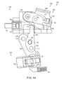
FIG. 1 is a cross-sectional view of a handle of a surgical instrument illustrated with some components removed in accordance with at least one embodiment. -
FIG. 2 illustrates the handle ofFIG. 1 in an unactuated configuration with various components removed. -
FIG. 3 is an elevational view of an end effector of the surgical instrument ofFIG. 1 illustrated in an open configuration and the distal end of a knife bar in an unadvanced position. -
FIG. 4 illustrates a trigger and a first drive system of the handle ofFIG. 2 in a partially actuated configuration. -
FIG. 5 is an elevational view of the end effector ofFIG. 3 illustrated in a partially closed configuration and the knife bar ofFIG. 3 in a partially advanced position. -
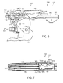
FIG. 6 illustrates a toggle clamp of the first drive system ofFIG. 4 in a completely actuated configuration. -
FIG. 7 is an elevational view of the end effector ofFIG. 3 illustrated in a fully closed configuration and the knife bar in a partially advanced position. -
FIG. 8 is a detail view of a yoke spring positioned intermediate a shaft of the surgical instrument ofFIG. 1 and a yoke of the first drive system ofFIG. 4 . -
FIG. 9 illustrates a lock system for locking and unlocking a second drive system of the handle ofFIG. 2 , wherein the lock system is illustrated in an unactuated and locked configuration.FIG. 9 further illustrates a portion of the first drive system ofFIG. 4 in an unactuated configuration. -
FIG. 10 illustrates the lock system ofFIG. 9 in an actuated, but locked configuration and the first drive system ofFIG. 4 in an unactuated configuration. -
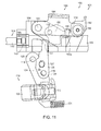
FIG. 11 illustrates the lock system ofFIG. 9 in an actuated and unlocked configuration and the first drive system ofFIG. 4 in an actuated configuration. -
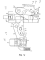
FIG. 12 illustrates the lock system ofFIG. 9 in an unactuated and locked configuration and the first drive system ofFIG. 4 in an actuated configuration. -
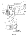
FIG. 13 illustrates the lock system ofFIG. 9 in an actuated and unlocked configuration and the first drive system ofFIG. 4 in an actuated configuration. -
FIG. 14 illustrates the lock system ofFIG. 9 returned to a locked configuration. -
FIG. 15 illustrates the toggle clamp of the first drive system in a completely actuated configuration and the trigger ofFIG. 4 operably engaged with a second drive system. -
FIG. 16 illustrates a trigger gear portion of the trigger ofFIG. 4 operably engaged with a compound gear system of the second drive system. -
FIG. 17 illustrates the end effector ofFIG. 3 in a fully closed position and the knife bar ofFIG. 3 in a partially advanced position. -
FIG. 18 illustrates the trigger ofFIG. 4 in a fully actuated position and a rack of the second drive system ofFIG. 15 in a fully advanced position. -
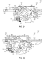
FIG. 19 illustrates the end effector ofFIG. 3 in a fully closed position and the knife bar ofFIG. 3 in a fully advanced position proximal to a distal end of the end effector. -
FIG. 20 is a detail view of the distal end of the end effector ofFIG. 19 . -
FIG. 21 illustrates a return plate of the handle ofFIG. 2 operably engaged with the trigger gear ofFIG. 16 .FIG. 21 also illustrates the trigger ofFIG. 4 and the rack ofFIG. 18 in a partially retracted, or partially returned, position. -
FIG. 22 illustrates the trigger ofFIG. 4 and the rack ofFIG. 18 in a further partially retracted, or further partially returned, position. -
FIG. 23 illustrates the trigger ofFIG. 4 engaged with the toggle clamp ofFIG. 6 and the toggle clamp being moved from its fully actuated configuration to a partially actuated configuration.FIG. 23 also illustrates the rack ofFIG. 18 in a further partially retracted, or further partially returned, position and the lock system ofFIG. 9 re-engaged with the rack ofFIG. 18 . -
FIG. 24 illustrates the toggle clamp ofFIG. 6 in a further partially actuated configuration and the rack ofFIG. 18 in a further partially retracted, or further partially returned, position. -
FIG. 25 illustrates the end effector ofFIG. 3 in a partially opened position and the knife bar ofFIG. 3 in a partially retracted position. -
FIG. 26 illustrates the toggle clamp ofFIG. 6 in an unactuated configuration. -
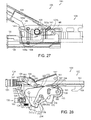
FIG. 27 illustrates the end effector ofFIG. 3 in a fully opened position and the knife bar ofFIG. 3 in a fully retracted position. -
FIG. 28 illustrates the toggle clamp ofFIG. 6 in an unactuated configuration and the rack ofFIG. 18 in a fully retracted position. -
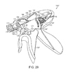
FIG. 29 is a perspective view of a handle of an alternative embodiment of a surgical instrument in an unactuated configuration illustrated with various components removed. -
FIG. 30 is another perspective view of the handle ofFIG. 29 in a partially actuated position illustrating a trigger coming into operative engagement with a gear of a second drive system. -
FIG. 31 is a perspective view of the lock system ofFIG. 9 in an unactuated, but locked configuration with an alternative embodiment of a rack of the second drive system. -
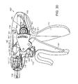
FIG. 32 is an elevational view of the lock system ofFIG. 9 in the unactuated, but locked configuration ofFIG. 31 .FIG. 32 further illustrates a button switch of the lock system in an unactuated configuration. -
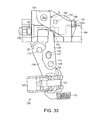
FIG. 33 illustrates the button switch ofFIG. 32 in an actuated position. -
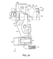
FIG. 34 illustrates the button switch ofFIG. 32 in an actuated position, a link of the lock system in an actuated position, and the lock of the lock system in an unlocked position. -
FIG. 34A is a detail view of the lock ofFIG. 34 and a lock spring configured to bias the lock into engagement with the rack. -
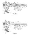
FIG. 35 illustrates the lock system ofFIG. 9 in an actuated, unlocked configuration and the rack ofFIG. 31 in an unadvanced position. -
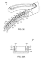
FIG. 36 illustrates the lock system ofFIG. 9 in an actuated, unlocked configuration and the rack ofFIG. 18 in an unadvanced position. -
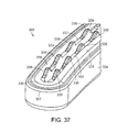
FIG. 37 illustrates a jaw of an end effector in accordance with at least one embodiment. -
FIG. 38 illustrates a jaw of an end effector comprising steam control paths in accordance with at least one embodiment. -
FIG. 38A is a cross-sectional view of the jaw ofFIG. 38 illustrating the steam control paths extending through an electrode of the end effector. Various components of the end effector have been removed inFIG. 38A . -
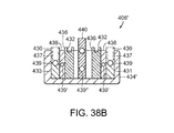
FIG. 38B is a cross-sectional view of a jaw of an alternative embodiment of an end effector illustrating steam control paths in supply electrodes, return electrodes, insulators positioned intermediate the supply electrodes and the return electrodes, and a cutting member movable within the end effector. -
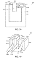
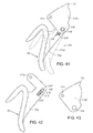
FIG. 39 illustrates a jaw of an end effector comprising a movable electrode. -
FIG. 40 illustrates a jaw of an end effector comprising first and second insulators which are movable relative to an electrode. -
FIG. 41 illustrates a trigger assembly of an alternative embodiment of a surgical instrument, wherein the trigger assembly further comprises a mechanism for limiting the force that can be transmitted through the trigger assembly.FIG. 41 further illustrates a first part of the trigger assembly (illustrated with phantom lines) moved relative to a second part of the trigger assembly. -
FIG. 42 is an elevational view of the first part of the trigger assembly. -
FIG. 43 is an elevational view of the second part of the trigger assembly. -
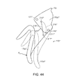
FIG. 44 illustrates a trigger assembly of an alternative embodiment of a surgical instrument, wherein the trigger assembly further comprises a mechanism for limiting the force that can be transmitted through the trigger assembly.FIG. 44 further illustrates a first part of the trigger assembly (illustrated with phantom lines) moved relative to a second part of the trigger assembly. -
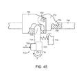
FIG. 45 is a diagram of an energy trigger assembly in accordance with at least one alternative embodiment of the present invention. -
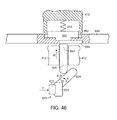
FIG. 46 is a diagram of another energy trigger assembly in accordance with at least one alternative embodiment of the present invention. - Corresponding reference characters indicate corresponding parts throughout the several views. The exemplifications set out herein illustrate various embodiments of the invention, in one form, and such exemplifications are not to be construed as limiting the scope of the invention in any manner.
- Various embodiments are directed to apparatuses, systems, and methods for the treatment of tissue Numerous specific details are set forth to provide a thorough understanding of the overall structure, function, manufacture, and use of the embodiments as described in the specification and illustrated in the accompanying drawings. It will be understood by those skilled in the art, however, that the embodiments may be practiced without such specific details. In other instances, well-known operations, components, and elements have not been described in detail so as not to obscure the embodiments described in the specification. Those of ordinary skill in the art will understand that the embodiments described and illustrated herein are nonlimiting examples, and thus it can be appreciated that the specific structural and functional details disclosed herein may be representative and do not necessarily limit the scope of the embodiments, the scope of which is defined solely by the appended claims.
- Reference throughout the specification to "various embodiments," "some embodiments," "one embodiment," or "an embodiment", or the like, means that a particular feature, structure, or characteristic described in connection with the embodiment is included in at least one embodiment. Thus, appearances of the phrases "in various embodiments," "in some embodiments," "in one embodiment," or "in an embodiment", or the like, in places throughout the specification are not necessarily all referring to the same embodiment. Furthermore, the particular features, structures, or characteristics may be combined in any suitable manner in one or more embodiments. Thus, the particular features, structures, or characteristics illustrated or described in connection with one embodiment may be combined, in whole or in part, with the features structures, or characteristics of one or more other embodiments without limitation.
- It will be appreciated that the terms "proximal" and "distal" may be used throughout the specification with reference to a clinician manipulating one end of an instrument used to treat a patient. The term "proximal" refers to the portion of the instrument closest to the clinician and the term "distal" refers to the portion located furthest from the clinician. It will be further appreciated that for conciseness and clarity, spatial terms such as "vertical," "horizontal," "up," and "down" may be used herein with respect to the illustrated embodiments. However, surgical instruments may be used in many orientations and positions, and these terms are not intended to be limiting and absolute.
- The entire disclosures of the following commonly-owned, non-provisional United States patent applications are hereby incorporated by reference herein:
- SURGICAL INSTRUMENT COMPRISING AN ENERGY TRIGGER LOCKOUT, filed on even date herewith, Atty. Docket No. END6675USNP1/090329;
- SURGICAL INSTRUMENT FOR TRANSMITTING ENERGY TO TISSUE COMPRISING STEAM CONTROL PATHS, filed on even date herewith, Atty. Docket No. END6675USNP4/090333;
- SURGICAL INSTRUMENT FOR TRANSMITTING ENERGY TO TISSUE COMPRISING NON-CODNDUCTIVE GRASPING PORTIONS, filed on even date herewith, Atty. Docket No. END6675USNP2/090331; and
- SURGICAL INSTRUMENT FOR TRANSMITTING ENERGY TO TISSUE COMPRISING A MOVABLE ELECTRODE OR INSULATOR, filed on even date herewith, Atty. Docket No. END6675USNP3/090332.
- The entire disclosures of the following non-provisional United States patents are hereby incorporated by reference herein:
-
U.S. Patent No. 7,381,209 , entitled ELECTROSURGICAL INSTRUMENT; -
U.S. Patent No. 7,354,440 , entitled ELECTROSURGICAL INSTRUMENT AND METHOD OF USE; -
U.S. Patent No. 7,311,709 , entitled ELECTROSURGICAL INSTRUMENT AND METHOD OF USE; -
U.S. Patent No. 7,309,849 , entitled POLYMER COMPOSITIONS EXHIBITING A PTC PROPERTY AND METHODS OF FABRICATION; -
U.S. Patent No. 7,220,951 , entitled SURGICAL SEALING SURFACES AND METHODS OF USE; -
U.S. Patent No. 7,189,233 , entitled ELECTROSURGICAL INSTRUMENT; -
U.S. Patent No. 7,186,253 , entitled ELECTROSURGICAL JAW STRUCTURE FOR CONTROLLED ENERGY DELIVERY; -
U.S. Patent No. 7,169,146 , entitled ELECTROSURGICAL PROBE AND METHOD OF USE; -
U.S. Patent No. 7,125,409 , entitled ELECTROSURGICAL WORKING END FOR CONTROLLED ENERGY DELIVERY; and -
U.S. Patent No. 7,112,201 , entitled ELECTROSURGICAL INSTRUMENT AND METHOD OF USE. - A surgical instrument can be configured to supply energy, such as electrical energy and/or heat energy, for example, to the tissue of a patient. In various embodiments, referring now to
FIG. 1 , a surgical instrument, such assurgical instrument 100, for example, can comprise ahandle 102, ashaft 104, and an end effector 106 (FIG. 3 ). As described in greater detail below, thehandle 102 can comprise one or more switches or triggers which can be configured to supply electrical energy to endeffector 106 and/or advance a knife or cutting member within theend effector 106, for example, in order to transect the tissue positioned within theend effector 106. - In various embodiments, referring to
FIG. 1 , thehandle 102 can comprise one or more electrical inputs, such as input, or terminal, 110, for example, which can be operably coupled with a power supply, such as a voltage supply, for example. In various embodiments, such a power supply can provide an electrical current to thesurgical instrument 100, wherein the magnitude, duration, wave form, and/or frequency, for example, of the current can be sufficiently controlled or modulated to provide a desired amount of energy to thesurgical instrument 100. Such power supplies are well known within the art and a more detailed description thereof is not required. In various embodiments, thehandle 102 can comprise ahandle body 112 which, as described in greater detail below, can be configured to operably support a switch or trigger, such astrigger system 120, for example, which can be configured to electrically coupleelectrical input 110 with a conductor inshaft 104 such that the current supplied to input 110 can be transmitted to endeffector 106. In various embodiments, referring toFIG. 1 , handlebody 112 can comprise two portions which are assembled together to formhandle body 112. As the reader will note, only one of the portions, or halves, is depicted inFIG. 1 , although the other portion, or half, can be a mirror image of, or at least substantially similar to, the half depicted inFIG. 1 . In various embodiments, the halves ofhandle body 112 can be snap-fit, press-fit, adhered, and/or fastened to one another. - In various embodiments, further to the above, the electrical conductor within the
shaft 104 can comprise a wire, such as insulated wire, for example, which can extend betweentrigger system 120 and an electrode 130 (FIG. 3 ) inend effector 106. In certain embodiments, referring again toFIG. 1 , thehandle 102 can further comprise asupply wire 114 which can be electrically coupled with an electrical supply conductor (not illustrated) encased within an outer housing, or spine, 105 (FIG. 8 ) of theshaft 104. In at least one embodiment, the supply conductor can comprise a conductive insert, comprised of copper, for example, which is at least partially positioned within an insulative plastic jacket or sheath, for example, of thespine 105. In certain circumstances, the plastic jacket can be molded over the conductive insert during an injection molding process. In various embodiments, referring again toFIG. 1 , thehandle 102 can comprise aslip ring 116 which can be configured to electricallycouple wire 114 with the supply conductor withinshaft 104. More particularly, in at least one embodiment, theslip ring 116 can comprise a circular, or an at least semi-circular, contact, for example, mounted to handlebody 102 which can remain in contact with a corresponding circular, or an at least semi-circular, contact mounted toshaft 104. Such corresponding contacts can permit relative rotational movement betweenshaft 104 and handle 102 and yet still provide an electrical path betweenwire 114 and the electrical supply conductor withinshaft 104. - In various embodiments, the
shaft 104 can further comprise another slip ring connector which, similar to the above, can maintain electrical contact between the supply conductor ofshaft 104 and a supply contact 132 (FIG. 3 ) ofelectrode 130. As described in greater detail below, electrical current can flow from theelectrical input 110, throughsupply wire 114, through the electrical conductor inshaft 104, and into theelectrode 130 such that current can flow from theelectrode 130 and into the tissue captured within theend effector 106. In various embodiments, as also described in greater detail below, the end effector can further comprise one or more return electrodes and/or conductors which can comprise a return path, or circuit, for the current. In at least one embodiment, similar to the above, the return path can comprise a slip ring contact operably coupled with a return electrode in theend effector 106 and a return conductor embedded within theshaft 104, for example. Also similar to the above, thehandle 102 can further comprise aslip ring 117, for example, which can maintain the return conductor withinshaft 104 in electrical contact withreturn wire 115. In at least one such embodiment, thereturn wire 115 can extend between theslip ring 117 and an electrical output, or terminal, which can, in various embodiments, be positioned adjacent to electrical input, or terminal, 110. - Further to the above, referring to
FIG. 37 , anend effector 306 can comprise anelectrode 330 which can extend between a proximal end ofend effector 306 and adistal end 307 ofend effector 306. In at least one such embodiment, theelectrode 330 can comprise a firstlateral portion 331 extending along a first side ofjaw member 334, a secondlateral portion 333 extending along a second side ofjaw member 334, and a transverseintermediate portion 335 connecting the firstlateral portion 331 and the secondlateral portion 333. In various embodiments, further to the above, the first jaw member can further comprise a return electrode and/or the end effector can further comprise a second jaw member having a return electrode which can be positioned opposite the first jaw member. In any event, referring again toFIG. 1 , thetrigger system 120 can comprise abutton 122 which can be selectively actuated in order to electrically couple theelectrical input 110 withsupply wire 114 and/or selectively actuated in order to electrically couple thereturn wire 115 with the electrical output ofhandle 102. More particularly, in at least one embodiment, thebutton 122 can be movable between an undepressed, or unactuated, position in which current cannot flow toelectrode 130, and a depressed, or actuated, position in which current can flow toelectrode 130. Although thebutton 122, and/or any similar button, can be used to actuate theswitch 123, and/or any other suitable switch, other energy actuation mechanisms, such as toggles, levers, and/or any suitable actuators, can be used in addition to or in lieu of the above. - When electrical current is supplied to an electrode, referring again to
FIG. 37 , the electrical current can pass through the tissue positioned against and/or surrounding theelectrode 330, for example. In various circumstances, the current flowing through theelectrode 330 can generate heat within the electrode and the surrounding tissue. In certain circumstances, the heat can denature the collagen within the tissue and, in co-operation with clamping pressure provided by the jaws of the end effector, the denatured collagen can form a seal within the tissue, for example. In at least one circumstance, thefirst side 331 ofelectrode 330 can be configured to create a first seal within the tissue and thesecond side 333 ofelectrode 330 can be configured to create a second seal within the tissue. Other embodiments are envisioned in which multiple electrodes, and/or multiple electrode portions, can create any suitable number of seals within the tissue. In various embodiments, as described in greater detail below, one or more of the jaw members of an end effector can comprise grasping portions which can be utilized to manipulate tissue within a surgical site and/or position and hold the tissue within the end effector. - In at least one embodiment, referring to
FIG. 37 ,first jaw member 334 can comprise at least one grasping member, such as a graspingportion 337, for example, which can be comprised of an electrically non-conductive, or insulative, material, such as plastic and/or ceramic, for example. In use, the graspingportions 337 can hold the tissue within the end effector without conducting, or at least not significantly conducting, current and/or heat to the tissue. In various embodiments, as a result, the possibility of the treated tissue adhering to, or becoming stuck to, the graspingportions 337 can be reduced or eliminated. In various embodiments, each graspingportion 337 can comprise an array or row ofteeth 339, for example, wherein, in at least one embodiment, a first grasping portion can comprise a first array or row ofteeth 339 and a second grasping portion can comprise a second array or row ofteeth 339. In at least one such embodiment, the first row ofteeth 339 can be positioned adjacent to the firstlateral portion 331 ofelectrode 330 and the second row ofteeth 339 can be positioned adjacent to the secondlateral portion 333 ofelectrode 330. - In various circumstances, further to the above, the grasping
portions 337 can be comprised of an electrically non-conductive plastic, glass, and/or ceramic, for example, and, in at least one embodiment, the graspingportions 337 can be formed by an injection molding process. In certain embodiments, at least one lubricant additive, such as Teflon, for example, can be mixed or embedded within the plastic. In various circumstances, the one or more lubricants can prevent, or at least inhibit, the tissue captured within theend effector 306 from sticking or adhering to theteeth 339, for example. In addition to or in lieu of the above, in certain embodiments, at least one lubricant, such as Teflon, for example, can be coated on the graspingportions 337. In certain embodiments, the graspingportions 337 can be comprised of an electrically conductive material which can be coated, or at least partially coated, with an electrically non-conductive material, for example - Owing to current flowing through the tissue and/or the heat generated by the one or more electrodes of an end effector of the surgical instrument, water, and/or other fluids, within the tissue can be vaporized. In certain circumstances, the heated vapors, such as steam, for example, can flow out of the end effector and into the surgical site surrounding the end effector. In various circumstances, the heated vapors can damage the surrounding tissue. In various embodiments, referring now to
FIG. 38 , at least one of the jaws, such asfirst jaw 434, for example, ofend effector 406 can comprise at least one steam control path, passage, or conduit for conveying the steam, and/or other vapors created by the current and/or heat, away from the surgical site. In certain embodiments, an electrode, such aselectrode 430, for example, can comprise an electrode body and at least one steam control path therein. In at least one embodiment, referring toFIG. 38A , the steam control path can comprise one ormore passages 439 which can extend longitudinally through the firstlateral portion 431 and the secondlateral portion 433 ofelectrode 430, for example. The steam control paths can further comprise one or more passages, or holes, 437 which can extend between an outside surface ofelectrode 430 and thepassages 439 such that steam can flow from the tissue being treated, through theholes 437, and into thepassages 439. In at least one embodiment, thepassage 439 extending though the firstlateral portion 431 and thepassage 439 extending through the secondlateral portion 433 can be in fluid communication via a passage withinintermediate portion 435 ofelectrode 430. In various embodiments, the shaft of the surgical instrument, such asshaft 104 ofsurgical instrument 100, for example, can comprise one or more passages or conduits therein which can be in fluid communication with thepassages 439, for example, such that the heated vapors can be conveyed away from the end effector and out of the patient. In at least one such embodiment, the handle of the surgical instrument, such ashandle 102, for example, can comprise at least one vent configured to allow the heated vapors to vent into the atmosphere surrounding the patient, for example. - In various embodiments, referring now to
FIG. 38B , a jaw 434' of an end effector 406' can comprise, similar to the above, asupply electrode 430 having first andsecond portions paths comprising passages return electrode 436 and one or more electricallynon-conductive insulators 438 positioned intermediate portions of thesupply electrode 430 and portions of thereturn electrode 436. In various embodiments, the return electrode and/or the insulators can comprise one or more steam control paths for conveying steam away from the tissue being treated. For example, the return electrode can comprise one ormore channels 432 therein which can be configured to convey the steam in a space intermediate the tissue and an outside surface of thereturn electrode 436. Also, for example, theinsulators 438 can comprise one or more passages 439' extending therethrough. Althoughpassages channels 432 are illustrated as having substantially orthogonal sidewalls, the sidewalls of the channels can comprise any suitable configuration, such as arcuate and/or semi-circular configurations, for example. In any event, any one of the supply electrode, return electrode, and/or insulators can comprise any suitable number of exterior channels and/or internal passages therein for conveying heated vapors away from the tissue in the end effector. In certain embodiments, referring again toFIG. 38B , a cuttingmember 440 can comprise one ormore steam paths 439" extending therethrough. - As described above, electrical energy, or current, can be supplied to the electrodes of an end effector, such as
electrode 130 ofend effector 106, for example, in order to treat, heat, and/or seal tissue captured within theend effector 106. As also described above, the tissue can be transected by a knife or cutting member. In various circumstances, however, it may not be desirable to transect the tissue prior to supplyingelectrode 130 with current and/or prior to the application of heat to the tissue. In various embodiments described herein,surgical instrument 100, for example, can comprise a trigger system, such astrigger system 120, for example, which can be configured to prevent the cutting member 140 (FIG. 3 ) ofsurgical instrument 100 from being advanced toward thedistal end 107 ofend effector 106 prior to the electrical current being supplied toelectrode 130. In certain embodiments, the cuttingmember 140 can be advanced at the same time that current is supplied toelectrode 130. In certain other embodiments, the current can be supplied toelectrode 130 prior to cuttingmember 140 being advanced to transect the tissue. - In various embodiments, referring now to
FIGS. 31-36 , thetrigger system 120 can comprise anenergy actuation button 122 mounted to afirst link 124, asecond link 126 operably coupled withfirst link 124, and apivotable lock 150 which can be moved between a locked position and an unlocked position bysecond link 126. Thebutton 122 can be moveable between an unactuated, or undepressed, position (FIG. 32 ) and an actuated, or depressed, position (FIG. 33 ) in order to electrically connect, or couple, afirst portion 114a ofsupply wire 114 and asecond portion 114b ofsupply wire 114. More particularly, thetrigger system 120 can further comprise aswitch 123 mounted tofirst link 124 which can be switched, or closed, whenbutton 122 is depressed such that current can flow from theelectrical input 110, through the firstsupply wire portion 114a, and into the secondsupply wire portion 114b andslip ring 116. As described above, the current can then flow toelectrode 130, throughreturn wire 117, and then through the electrical outlet in order to complete the electrical circuit. In various embodiments, theswitch 123 can comprise a spring, such as a linear coil spring, for example, positioned therein which can be compressed when thebutton 122 is moved from its unactuated position to its actuated position. In at least one such embodiment, the coil spring can be positioned intermediate thebutton 122 and a housing of theswitch 123 and/orfirst link 124. In any event, in certain embodiments, a force is required to compress the spring and, in addition, thebutton 122 is required to move a predetermined distance in order to actuateswitch 123. - In various embodiments, further to the above, the force applied to
button 122 in order to actuateswitch 123 can causefirst link 124 to move. More particularly, the force applied tobutton 122 can be transmitted through the coil spring to switch 123 wherein the force can then be transferred tofirst link 124. In at least one embodiment, referring again toFIG. 32 , thefirst link 124 can comprise afirst end 125 pivotably mounted to handlebody 112 via a pivot or pin 118 extending fromhandle body 112 and through an aperture infirst end 125. Whenfirst link 124 is moved by the force, thefirst link 124 can rotate or pivot about an axis defined bypin 118 in a direction indicated by arrow A (FIG. 32 ). In various embodiments, thefirst link 124 can further comprise adrive member 127 extending therefrom which can be configured to movesecond link 126. In at least one embodiment, thesecond link 126 can comprise afirst end 129 pivotably mounted to handlebody 112 via a pivot or pin 119 extending fromhandle body 112 and through an aperture infirst end 129. Thedrive member 127 can extend into aslot 128 insecond link 126 such that, when thefirst link 124 is rotated aboutpivot 118 in direction A, thesecond link 126 can be rotated aboutpivot 119 in a direction indicated by arrow B (FIG. 32 ). More particularly, thedrive member 127 extending intoslot 128 can engage a sidewall of theslot 128 so as to transmit movement betweenfirst link 124 andsecond link 126. In various embodiments, further to the above, thesecond link 126 can further comprise asecond end 151 which can be configured to engagerack 150 and rotaterack lock 150 between an unactuated, locked position (FIG. 33 ) and an actuated, unlocked position (FIG. 34 ). More particularly, whensecond link 126 is rotated in direction B, therack lock 150 can be rotated in a direction indicated by arrow C (FIG. 32 ) about an axis defined bypivot 152 onyoke 154. Whenrack lock 150 is sufficiently rotated in direction C, as described in greater detail further below,tooth 155 extending fromrack lock 150 may be sufficiently removed fromnotch 162a inrack 160 such thatrack 160 can be moved relative to lock 150. - As described above, the force applied to
button 122 in order to actuateswitch 123 can rotatefirst link 124 aboutpivot 118, rotatesecond link 126 aboutpivot 119, and rotaterack lock 150 between locked and unlocked positions. In at least one embodiment, such a force can be sufficient to actuateswitch 123 and unlockrack 150 at the same time, or at least substantially the same time. In such embodiments, energy can be supplied to theelectrode 130 at the same time that rack 160 becomes unlocked and capable of advancingknife bar 140 distally withinend effector 106 as described in greater detail below. In various circumstances, as a result, thetrigger system 120 can assure that the tissue positioned within the end effector is not transected before it is at least partially treated and/or sealed. In various other embodiments, referring again toFIG. 32 , thetrigger system 120 can further comprise atrigger spring 121 operably engaged with thefirst link 124, for example, which can be configured to resist the movement offirst link 124 in the direction indicated by arrow A. In at least one embodiment, the force applied tobutton 122 to actuateswitch 123 may be insufficient to rotatefirst link 124 and second link 126 a sufficient distance to moverack lock 150 into its unlocked position. In such embodiments, theswitch 123 can be actuated to supplyelectrode 130 with current while therack 160 can remain locked in place byrack lock 150. More particularly, further to the above, thetooth 155 ofrack lock 150 can remain biased intofirst notch 162a bylock spring 156 such thatrack 160 is prevented from moving, or at least substantially moving, relative to racklock 150. In various other embodiments, further to the above, a rack lock may be slid between a first position in which it is locked with a rack, such asrack 160, for example, and a second position in which it is unlocked from the rack. In at least one such embodiment, the rack lock can be moved along a straight line. - In order to overcome the biasing force of
trigger spring 121, further to the above, a larger, or second, force may need to be applied tobutton 122 and/orfirst link 124. More particularly, in the event that the force, or first force, used to depressbutton 122 and actuateswitch 123 is insufficient to unlockrack lock 150, a second, or larger, force can be applied tobutton 122, for example, in order to sufficiently compressspring 121, sufficiently rotatefirst link 124 andsecond link 126, and rotaterack lock 150 into an unlocked position. In such circumstances, a clinician may apply a light force tobutton 122 in order to actuate the electrical energy system and a heavier force tobutton 122 in order to unlock therack 160. In various embodiments, referring toFIG. 1 ,trigger spring 121 can be positioned intermediatefirst link 124 and handlebody 112 such thattrigger spring 121 is compressed asfirst link 124 is rotated in the direction indicated by arrow A. The length and/or stiffness oftrigger spring 121 can be selected such that the coil spring withinswitch 123 is sufficiently compressed to supplyelectrode 130 with electrical energy before thetrigger spring 121 is sufficiently compressed to unlockrack 160. In such embodiments, as a result, the treatment or sealing of the tissue positioned within theend effector 106, for example, can begin beforerack 160 and cuttingmember 140 can be advanced. In certain circumstances, the difference between the first force and the second force can be large enough such that a surgeon, or other clinician, using thesurgical instrument 100 may be provided with a tactile feedback as to whether the surgical instrument is in a first operating condition in which energy is being applied to the tissue and the cutting member is not being advanced within the end effector and a second operating condition in which energy is being applied to the tissue and the cutting member is being advanced within the end effector to transect the tissue. For example, the switch spring and thetrigger spring 121 can be selected such that a significantly smaller force is required to depressbutton 122 and actuateswitch 123 as compared to a significantly larger force required to unlockrack lock 150. In the various alternative embodiments where it may be desirable for the electrical energy to be supplied toelectrode 130 at the same time, or at least substantially the same time, that therack 160 becomes unlocked, the stiffness of the spring inswitch 123 and the stiffness oftrigger spring 121 can be selected such that a force which is sufficient to actuatebutton 122 can also be sufficient to rotatelock 150 into an unlocked configuration. In at least one such embodiment, the force necessary to actuatebutton 122 can be the same, or at least substantially the same, as the force necessary to unlockrack 160. - In various circumstances, the surgeon can release
button 122 such that the spring ofswitch 123 can returnbutton 122 to an unactuated position and operably disconnectfirst portion 114a andsecond portion 114b ofsupply wire 114. In such circumstances, electrical current may no longer flow toelectrode 130 and, as a result, theelectrode 130 and the tissue within the end effector may begin to cool. In addition to the above, thetrigger spring 121 may return first link 124 and/orsecond link 126 to their unactuated positions and thelock spring 156 may returnrack lock 150 to an unlocked position. More particularly, referring now toFIG. 36 , in the event that thebutton 122 is released and therack 160 has not been advanced, or has been returned to its starting position, thelock spring 156 can reposition thelock tooth 155 within thenotch 162a and relock therack 160 in position. In various other circumstances, therack 160 may be sufficiently advanced such that therack tooth 155 cannot be reseated within thenotch 162a and, as a result, thelock spring 156 may position thetooth 155 against atop surface 161 ofrack 160 in an unlocked position. In such circumstances, therack 160 and the cuttingmember 140 can be advanced within the tissue without current flowing to theelectrode 130. In various other embodiments, referring now toFIG. 35 , a rack 160' can comprise a plurality ofnotches 162a-162e, for example, which can, once thebutton 122 has been released, allow thelock spring 156 to return thelock 150 to a locked configuration even though the rack 160' and the cuttingmember 140 have already been advanced. More particularly, depending on the distance that rack 160 has been advanced, thelock spring 156 can position thelock tooth 155 in any one of thenotches 162b-162e, for example. In order to prevent thelock 150 from re-engaging with the rack 160' as it is being advanced, in at least one such embodiment, the surgeon may keep thebutton 122 depressed and thefirst link 124 and thesecond link 126 sufficiently rotated in order to keep thelock 150 in an unlocked position. In such circumstances, owing to the constant depression ofbutton 122, electrical energy can be supplied to theelectrode 130 during the entire, or at least substantially entire, advancement ofrack 160 and cuttingmember 140. - As discussed above,
lock spring 156 can be configured to biaslock 150 into engagement withrack 160. In various embodiments, referring now toFIG. 34A ,lock spring 156 can comprise a torsion spring including acoil 156a positioned aboutpivot pin 152, a first end extending fromcoil 156a mounted toyoke 154, and a second end 156b. In at least one embodiment, the second end 156b can comprise a torque arm which, when thelock 150 is rotated aboutpivot pin 152 as described above, the second end 156b can torque or compress thespring coil 156a. In such circumstances, thespring 156 can store potential energy therein which, when released, can act to movelock 150 from its unlocked position into its locked position. In various embodiments, the second end 156b can comprise a hook orattachment portion 156c which can mount the second end 156b to lock 150 such that the second end 156b moves thelock 150. - In various embodiments, referring again to
FIGS. 32-34 , the distance to movebutton 122 from an unactuated position to an actuated position can be shorter than the distance to rotate link 124 sufficiently to movelock 150 between a locked position and an unlocked position. Stated another way, in various embodiments, the actuation ofbutton 122, although it may causefirst link 124 andsecond link 126 to rotate, may be insufficient to rotatefirst link 124 and second link 126 a sufficient distance to movelock 150 into its unlocked configuration. In at least one such embodiment, as a result, thebutton 122 can be depressed to supply electrical energy to theelectrode 130 while therack 160, for example, can remain locked in position byrack lock 150. In such circumstances, the tissue can be sealed, or at least partially sealed, before the cuttingmember 140 is advanced through the tissue within theend effector 106. In various circumstances, thebutton 122 and thefirst link 124 can be moved an additional distance in order to sufficiently rotatelock 150 into an unlocked configuration such thatrack 160 and cuttingmember 140 can be advanced into and/or through the tissue. Stated another way, in various embodiments, thebutton 122 can be moved a first distance to supply electrical current to electrode 130 although thebutton 122 can be moved a total distance which is greater than the first distance to unlockrack lock 150. In various embodiments, the difference between the first distance and the total distance thatbutton 122 is moved can be sufficient to provide a sufficiently large window of operation to allow the surgeon to movebutton 122 within a range of distances while not unlocking therack lock 150. In the various alternative embodiments where it may desired to supply electrical energy to electrode 130 at the same time, or at least substantially the same time, thatrack 160 becomes unlocked, the distance necessary to actuatebutton 122 may the same, or at least substantially the same, as the distance necessary to movelock 150 between its locked and unlocked configurations. - Once
rack lock 150 has been disengaged fromrack 160, as described above,rack 160 and cuttingmember 140 can be advanced toward distal end 107 (FIG. 3 ) ofend effector 106. In various embodiments, as described in greater detail below, the advancement of cuttingmember 140 can, one,move jaw 108 towardjaw 109 and, two, incise the tissue captured betweenjaw 108 andjaw 109. Referring toFIG. 1 , thehandle 102 can further comprise atrigger 170 which can be moved between an unactuated position, as illustrated inFIG. 1 , and an actuated position, as illustrated inFIG. 18 . The movement oftrigger 170 between its actuated position and unactuated position can define one stroke oftrigger 170, although such a stroke can comprise two different ranges of motion. More particularly, in at least one embodiment, the stroke can comprise a first range of motion which drives a first drive system and a second range of motion which drives a second drive system. In various embodiments, thetrigger 170, in co-operation with the first drive system, can advance therack 160 and the cuttingmember 140 between a first position (FIG. 3 ) and a second position (FIG. 7 ) during the first range of motion oftrigger 170, wherein thetrigger 170, in co-operation with the second drive system, can advance therack 160 and the cuttingmember 140 between a second position (FIG. 7 ) and a third position (FIG. 19 ) during the second range of motion oftrigger 170. When the cuttingmember 140 is moved between its first position (FIG. 3 ) and its second position (FIG. 7 ), as described in greater detail below, the cuttingmember 140 can move thesecond jaw 108 toward thefirst jaw 109 and clamp tissue positioned therebetween. When the cuttingmember 140 is moved between its second position (FIG. 7 ) and its third position (FIG. 19 ), as described in greater detail further below, the cuttingmember 140 can be advanced toward thedistal end 107 to incise the tissue clamped betweenjaw 108 andjaw 109. - In various embodiments, referring now to
FIG. 2 , the first drive system can comprise atoggle clamp 180 which can be moved between a first configuration (FIG. 2 ) associated with the first position (FIG. 3 ) of cuttingmember 140 and a second configuration (FIG. 6 ) associated with the second position (FIG. 7 ) of cuttingmember 140. Thetoggle clamp 180, referring again toFIG. 2 , can comprise afirst link 182 and asecond link 184. Thefirst link 182 can comprise a first end pivotably mounted to handlebody 112 atfirst pivot 181, via a pivot pin, for example, and, in addition, thesecond link 184 can comprise a first end pivotably mounted toyoke 154 at asecond pivot 183, also via a pivot pin, for example. Further to the above, thefirst link 182 and thesecond link 184 can each comprise second ends which are pivotably mounted to each other via anintermediate pivot pin 185, for example. In certain embodiments, theintermediate pivot pin 185 can comprise a vertex of an angle defined between a first line, or axis, 186 extending through the centers offirst pivot 181 andintermediate pivot 185 and a second line, or axis, 187 extending through the centers ofsecond pivot 183 andintermediate pivot 185. In various embodiments, thefirst line 186 and thesecond line 187 can define a vertex angle α therebetween. Opposite vertex angle α is a line, or axis, 188 defined between the center offirst pivot 181 and the center ofsecond pivot 183. Whentoggle clamp 180 is in its first configuration, in various embodiments, the vertex angle α can be about 90 degrees and/or slightly greater than 90 degrees, for example. In at least one embodiment, angle α can be about 120 degrees whentoggle clamp 180 is in its first configuration, for example. Although such angles may be suitable in various circumstances, any other suitable angle can be used. - In various embodiments, further to the above, the
trigger 170 can be moved from its unactuated position (FIG. 2 ) into a partially actuated position (FIG. 4 ) as part of its first range of motion. As the reader will see when comparingFIG. 2 andFIG. 4 ,trigger 170 is pivotably mounted to handlebody 112 via apivot 171, such as a pivot pin, for example. Whentrigger 170 is rotated aboutpivot 171, trigger 170 can begin to move thetoggle clamp 180 from its first configuration (FIG. 2 ) into its second configuration (FIG. 6 ). More particularly, in at least one embodiment, thetrigger 170 can further comprise a cam, or driver, 172 extending therefrom which can be configured to engagefirst link 182 and lift the second end oflink 182 upwardly and, at the same time, rotate first link 182 aboutfirst pivot 181 in a direction indicated by arrow D (FIG. 4 ). Owing to the pivoted connection of the second ends offirst link 182 andsecond link 184, the upward movement of the second end offirst link 182 can cause the second end ofsecond link 184 to move upwardly and, at the same time, rotate aboutsecond pivot 183 in a direction indicated by arrow E (FIG. 4 ). In various embodiments, thefirst link 182 can comprise a cam, or drive,pocket 173 which can be engaged by cam, or driver, 172 in order to transmit the rotation oftrigger 170 tofirst link 182. In order to accommodate the upward movement of the second ends oflinks intermediate pivot 185, theyoke 154 can translate distally in a direction indicated by arrow F (FIG. 4 ). - In various embodiments, referring again to
FIG. 4 , the distal movement ofyoke 154 in the direction F can be transmitted to rack 160 and cuttingmember 140 such thatrack 160 and cuttingmember 140 are also moved in direction F. More particularly, further to the above, therack lock 150 mounted toyoke 154, when engaged withrack 160, can allow theyoke 154 to pull therack 160 distally when theyoke 154 is pushed distally bytoggle clamp 180 as described above. Furthermore, owing to the connection betweenrack 160 and cuttingmember 140, the distal movement ofrack 160 can be transmitted to cuttingmember 140. More particularly, in at least one embodiment, the cuttingmember 140 can comprise aproximal portion 142 which can be connected to thedistal end 165 ofrack 160. In various embodiments, such a connection can prevent, or at least inhibit, relative longitudinal movement between cutting memberproximal end 142 and rackdistal end 165 while permitting relative rotational movement therebetween owing to around head 143 of theproximal end 142 captured within a round cavity in thedistal end 165 ofrack 160. In any event, referring now toFIG. 5 , the proximal movement of cuttingmember 140 can, in at least one embodiment,cause cutting member 140 to engage thesecond jaw 108 and move, or rotate,second jaw 108 towardfirst jaw 109. More particularly, the cuttingmember 140 can comprise one or more cams, or cam pins, 144a which can be configured to engage one or more cam surfaces 145 onsecond jaw 108 and rotatesecond jaw 108 downwardly about one or more pivot pins 103, for example. - In various embodiments, further to the above, the rotation of
trigger 170 through its first range of motion can move thetoggle clamp 180 between its first, or unactuated, configuration (FIG. 2 ) and its second, or fully actuated, configuration (FIG. 6 ). Also further to the above, the movement of thetoggle clamp 180 between its first configuration and its second configuration can move the cuttingmember 140 between its first position (FIG. 3 ) and its second position (FIG. 7 ) and, as a result, movesecond jaw 108 between its fully open position (FIG. 3 ) and its fully closed position (FIG. 7 ). When comparing thetoggle clamp 180 in its second configuration as compared to its first configuration, the reader will note that the vertex angle α defined betweenfirst line 186 andsecond line 187 is about 180 degrees, for example. In at least one embodiment, the vertex angle α can be about 175 degrees, for example. Furthermore, the reader will note that thesecond pivot 183 has moved distally respect tofirst pivot 181 asyoke 154 has been moved distally as described above. As a result of the above, thetoggle clamp 180 can transmit a very large longitudinal force to rack 160 and cuttingmember 140 in the distal direction F. In fact, this very large longitudinal force can increase exponentially and/or asymptotically as the vertex angle α approaches approximately 180 degrees. This very large longitudinal force can apply a large biasing force tosecond jaw 108 such that a large clamping force, or pressure, is applied to the tissue positioned intermediate thefirst jaw 109 and thesecond jaw 108. - In various embodiments, referring now to
FIG. 8 , the distal movement ofyoke 154 can compress a yoke spring, such asaxial spring 147, for example,intermediate yoke 154 and aspine 105 ofshaft 104. In at least one embodiment, as described in greater detail below, theaxial spring 147 can store potential energy therein which can be released in order to at least partially retractrack 160 and cuttingmember 140. Although thetoggle clamp 180 is illustrated in its first, or unactuated configuration, inFIG. 8 , theaxial spring 147 is at least partially compressed betweenshaft spine 105 andyoke 154. In various circumstances, the compression force applied toshaft spine 105 andyoke 154 byspring 147 can provide an additional benefit of inhibiting relative movement betweenshaft spine 105 andyoke 154. - In various embodiments, referring now to
FIG. 9 which illustrates thetoggle clamp 180 in its first configuration and thetrigger assembly 120 in its unactuated configuration, therack lock 150 is in its locked position andrack 160 is in its unadvanced position. In such a configuration, further to the above and referring now toFIG. 10 , thetrigger assembly 120 can be actuated so as to rotatefirst link 124 aboutpivot 118 and rotatesecond link 126 aboutpivot 119; however, in circumstances where therack 160 and cutting member have not yet been advanced into their second positions, for example, the actuation oftrigger assembly 120 may not moverack lock 150 into its unlocked position. Upon the advancement ofrack 160 and cuttingmember 140 into their second positions, referring now toFIG. 11 , therack lock 150 can be moved into contact withsecond link 126 such thatrack lock 150 is rotated from its locked position to its unlocked position. Alternatively, referring now toFIG. 12 , therack 160 and cuttingmember 140 can be advanced from their first positions (FIG. 9 ) to their second positions (FIG. 12 ) when thetoggle clamp 180 is moved from its first configuration into its second configuration, as described above, and wherein, upon a sufficient actuation oftrigger assembly 120, as described above, thesecond link 126 can contactrack lock 150 and rotaterack lock 150 into its unlocked configuration as illustrated inFIG. 13 . In any event, upon the completion of its first range of motion, trigger 170 can, as described in greater detail below, become operably disengaged from the first drive system and/or operably engaged with the second drive system. - Referring now to
FIG. 15 which depicts thetrigger 170 at the end of its first range of motion, the reader will see that thecam 172 is no longer positioned withinpocket 173 infirst link 182. As a result, thecam 172 may no longer drive thetoggle clamp 180 despite any further rotation oftrigger 170 toward its actuated position (FIG. 18 ), and, as a result, thetrigger 170 may be operably disconnected from the first drive system. The reader will also see that, at this position oftrigger 170, thetrigger 170 has been moved into operative engagement withtrigger gear 175 and the second drive system. More particularly, referring now toFIG. 16 , thetrigger 170 can further comprise adrive pin 176 extending therefrom which is configured to contact thebottom surface 177 oftrigger gear 175 and, once engaged withtrigger gear 175, push, or rotate, thetrigger gear 175 upwardly such that thetrigger gear 175 rotates acompounding gear 191 of the rack andpinion system 190 astrigger 170 is moved through its second range of motion. As the reader will note, thetrigger gear 175 comprises an array ofteeth 178 which are operably engaged with, or meshed with, thecompounding gear 191 while thetrigger 170 is moved through its first range of motion, although, theteeth 178 do not drive thecompounding gear 191 during the first range of motion oftrigger 170. On the other hand, the rotation oftrigger 170 in its second range of motion can causetrigger gear 175 to drive or rotatecompounding gear 191 as described in greater detail further below. In various embodiments, further to the above, the disengagement ofcam 172 frompocket 173 infirst link 182 can occur at the same time, or at least substantially the same time, as thetrigger 170 comes into operative engagement withtrigger gear 175. Alternatively, thetrigger 170 may not come into operative engagement withtrigger gear 175 until after thecam 172 has been disengaged frompocket 173. In at least one such embodiment, the rotation oftrigger 170 may comprise a dwell period in which thetrigger 170 is not operatively engaged with either the first drive system of the second drive system. - Once
trigger 170 has been operatively engaged withtrigger gear 175, further to the above, the further rotation oftrigger 170 can, one, cause thecam 172 to move relative to abottom surface 187 offirst link 182, and, two, rotate compoundinggear 191. In at least one embodiment, thecompounding gear 191 can be mounted to apin 192 which can be rotatably mounted between the two halves ofhandle body 112. Referring again toFIG. 16 , the rack andpinion system 190 can further comprise an additional, or second, compoundinggear 193 which can be mounted to pin 192. In at least one such embodiment, the compounding gears 191, 193 can be mounted to pin 192 such that the rotation of one of compounding gears 191, 193 causes the rotation of the other of the compounding gears 191, 193. In various embodiments, the rack andpinion system 190 can further comprise athird compounding gear 195 which can be mounted to apin 194 which can be rotatably mounted between the two halves ofhandle body 112. As illustrated inFIG. 16 , thethird compounding gear 195 can be operably meshed with thesecond compounding gear 193 such that the rotation ofsecond compounding gear 193 can rotate thethird compounding gear 195. The rack andpinion system 190 can further comprise apinion gear 197 which can also be mounted to pin 194, wherein, similar to the above, thecompounding gear 195 and thepinion gear 197 can be mounted to pin 194 such that the rotation of one ofgears gears FIG. 16 , thepinion gear 197 is operably or meshingly engaged with therack teeth 164 onrack 160 such that the rotation ofpinion gear 197 can move, or displace, rack 160 along a straight, or at least substantially straight, path, for example. - During the second range of motion of
trigger 170, further to the above, the rotation oftrigger 170 can be transmitted topinion gear 197 via compounding gears 191, 193, and 195 such that, owing to the gear ratio ofgears trigger 170 can result in a large displacement ofrack 160 and cuttingmember 140. In various embodiments, as described above, the rotation oftrigger 170 through its second range of motion can move cuttingmember 140 between its second position (FIG. 17 ) and its third position (FIG. 19 ). In its second position, referring toFIG. 17 , the cuttingmember 140 can be positioned within theend effector 106 such that theknife edge 146 of cuttingmember 140 is positioned to be advanced through the tissue captured betweenfirst jaw 109 andsecond jaw 108, and owing to the rotation oftrigger 170,trigger gear 175, and gears 191, 193, 195, and 197, therack 160 can be displaced in the distal direction F so as to displace the cuttingmember 140 toward thedistal end 107 ofend effector 106. In its third position, referring toFIGS. 18 and 19 , the cuttingmember 140 can be positioned at thedistal end 107 ofend effector 106. In at least one embodiment, referring toFIG. 20 ,jaw 108 and/orjaw 109 can comprise aslot 149 which can be configured to receive at least a portion of cuttingmember 140 andguide cutting member 140 toward thedistal end 107. In certain embodiments, the cam pins 144a extending from cuttingmember 140 can be configured to ride on top ofcam surface 148a on the outside ofjaw 108 such thatjaw 108 is compressed towardjaw 109. Similarly, cuttingmember 140 can further comprise cam pins 144b extending therefrom which can be configured to ride oncam surface 148b on the outside ofjaw 109 such thatjaw 109 is compressed towardjaw 108. Stated another way, the cam pins 144a and 144b can engage thecam surfaces intermediate jaw 108 andjaw 109. In certain embodiments, referring again toFIG. 20 ,jaw 108 and/orjaw 109 can further comprise astop 147 which can be configured to stop the distal displacement of cuttingmember 140 through the tissue. In at least one embodiment, thestop 147 can be positioned proximally with respect to the distal end ofelectrode 130 such that theknife edge 146 may not transect tissue which has not been sealed. - Once the
trigger 170 has been moved through its second range of motion and/or at any suitable moment during the second range of motion, thetrigger 170 can be released. Upon the release oftrigger 170, a return spring, such as torsion spring 199 (FIG. 28 ), for example, can reverse the rotation of compoundinggears pinion gear 197 in order to retractrack 160 and cuttingmember 140 in a proximal direction, i.e., in a direction opposite direction F. In at least one embodiment, referring toFIG. 28 , one end of thetorsion spring 199 can be engaged with thecompounding gear 191 and another end of thetorsion spring 199 can be engaged with thehandle body 112, for example, such that potential energy stored within thetorsion spring 199 when therack 160 is advanced can be released when thetrigger 170 is released in order to rotatecompounding gear 191 in a reverse direction. In addition to the above, referring toFIG. 21 the reverse rotation of compoundinggear 191 can, owing to the meshing engagement oftrigger gear teeth 178 andcompounding gear 191, rotatetrigger gear 175 downwardly in a direction indicated by arrow G. In various embodiments, the downward rotation oftrigger gear 175 can be transmitted to trigger 170 via the interaction ofdrive surface 177 acting against thedrive pin 176 in order to retract, or return, thetrigger 170 through its second range of motion, as illustrated inFIG. 22 . In at least one embodiment, the surgical instrument can further comprise a reversingplate 200 which can be operably engaged withcompounding gear 191 such that the reverse rotation of compoundinggear 191 can also be transmitted to triggergear 175 via reversingplate 200. The reversingplate 200 can be keyed to compoundinggear 191 and/or pin 192 such that, as compoundinggear 191 is driven in a reverse direction byreturn spring 199, the reversingplate 200 is driven downwardly and rotated about an axis defined bypin 192 in a direction indicated by arrow H. In such circumstances, referring toFIG. 22 , the reversingplate 200 can act againstdrive pin 202 extending fromtrigger gear 175 to drivetrigger gear 175 downwardly. - In various embodiments, further to the above, the
return spring 199, viagears member 140 and therack 160 from their third position to their second position and allow therack lock 150 to re-engage therack 160 as illustrated inFIG. 23 . Owing to the re-engagement ofrack lock 150 withrack 160, theyoke spring 147 can pushyoke 154,rack 160, and cuttingmember 140 in a proximal direction, i.e., a direction opposite direction F. In various circumstances, theyoke spring 147, viayoke 154, can move therack 160 and the cuttingmember 140 from their second positions to their first positions. In addition to the above, whenyoke spring 147 pushesyoke 154 backward, theyoke 154 can drive, or collapse, thetoggle clamp 180 between its second configuration (FIG. 22 ) into its first configuration (FIG. 23 ). In such circumstances, referring toFIGS. 23 and 24 , thecam 172 extending fromtrigger 170 can become re-engaged with thepocket 173 infirst link 182 such that thefirst link 182 can drive thetrigger 170 through its first range of motion into its unactuated position as illustrated inFIG. 26 . - When the cutting
member 140 is returned to its first position from its second position, as described above and referring toFIGS. 25 and27 , the cuttingmember 140 can movesecond jaw 109 from its closed position to its open position. More particularly, in at least one embodiment, the cuttingmember 140 can further comprise at least oneopening cam pin 141 extending therefrom which, when moved proximally, can engagecam surface 101a onsecond jaw 109 such thatsecond jaw 109 is pivoted upwardly about pivot pins 103 into its open position as illustrated inFIG. 27 . Oncejaw 109 has been moved into its open position, thecam pin 141 can be further retracted such that it is positioned over and/or againstlock surface 101b which is positioned proximally with respect tocam surface 101a. In such circumstances, thesecond jaw 109 can be locked or held in an open position bycam pin 141. In any event, in order to assure that the cuttingmember 140 has been fully returned to its first position, thedrive pin 176 extending fromtrigger 170 can engage the sidewall of aslot 204 in reversingplate 200 astrigger 170 is returned to its unactuated position. More particularly, thedrive pin 176 can assure that the reversingplate 200, the compounding gears 191, 193, 195, and 197, and therack 160 have been returned to their initial positions and, as a result, assure that cuttingmember 140 has been returned to its initial position. - As described above, the
trigger 170 comprises adrive pin 176 which, at the end of the first range of motion oftrigger 170, can contact thedrive surface 177 oftrigger gear 175 in order to movetrigger gear 175 upwardly. In such circumstances, thetrigger 170 andtrigger gear 175 move together about a common axis of rotation defined bypivot 171. Whentrigger 170 is released and returned to its unactuated position, however, thetrigger 170 andtrigger gear 175 can, referring toFIGS. 21-24 , for example, move independently of one another and rotate relative to one another. More particularly, thetrigger 170 andtrigger gear 175 can move relative to one another about apivot 179 ontrigger 170 astrigger 170 is returned to its unactuated position and as thesurgical instrument 100 is reset to its initial configuration. - In various embodiments, referring now to
FIG. 41 , an alternative surgical instrument can comprise substantially the same components and systems assurgical instrument 100, although the alternative surgical instrument can comprise a trigger assembly 170' comprising afirst portion 170a' and asecond portion 170b'. In certain embodiments, relative movement between thefirst portion 170a' and thesecond portion 170b' is possible during the actuation of trigger 170'. More particularly, in at least one embodiment, a force overload mechanism can be positioned intermediate thefirst trigger portion 170a' and thesecond trigger portion 170b' such that, when the force applied to triggerportion 170a' exceeds a predetermined value, thetrigger portion 170a' can move relative to thetrigger portion 170b' and prevent any force in excess of the predetermined value from being transmitted to triggergear 175 via drive pin 176'. Referring now toFIG. 42 , thefirst trigger portion 170a' can comprise apivot hole 171a' which can be aligned with, referring toFIG. 43 , apivot hole 171b' insecond trigger portion 170b' wherein, when thefirst portion 170a' and thesecond portion 170b' are assembled together, as illustrated inFIG. 41 , thefirst portion 170a' and thesecond portion 170b' can rotate together about an axis defined by pivot 171'. More particularly, a force, or load, FA applied tofirst portion 170a' can causefirst portion 170a' to rotate about pivot 171' and, owing to drive pin 176', the rotation offirst portion 170a' can be transmitted tosecond portion 170b' in order to causesecond portion 170b' to be rotated about pivot 171'. In at least one embodiment, the drive pin 176' can be slidably positioned within a slot 212' withinfirst portion 170a', wherein thefirst portion 170a' can further comprise a spring, such as an axial compression 216', for example, configured to bias the drive pin 176' against the end 214' of slot 212'. As illustrated inFIG. 41 , the drive pin 176' can extend through a drive aperture 218' insecond portion 170b', wherein, in various circumstances, at least a portion of the force FA applied tofirst trigger portion 170a' can be transmitted through the spring 216', drive pin 176', and a sidewall of drive aperture 218' in order to apply a force tosecond trigger portion 170b'. - In various embodiments, further to the above, the force transmitted between the
first trigger portion 170a' and thesecond trigger portion 170b' can be represented by a force FT (FIG. 41 ) which is transmitted throughspring 216. As illustrated inFIG. 41 , the force FT can be aligned, or collinear, with the longitudinal, or axial, axis of spring 216'. When the force FT is at or below the predetermined, or threshold, value described above, thefirst portion 170a' and thesecond portion 170b' can move together with little, if any, relative movement therebetween. In at least one such embodiment, the spring 216' can be compressed between the drive pin 176' and a second sidewall 215' of theslot 212 such that the spring 216' is compressed by a preload force which is equal to, or at least substantially equal to, the predetermined threshold value. In such circumstances, the spring 216' may not be further compressed unless and if the force FT exceeds the predetermined threshold value. Once the force FT exceeds the predetermined threshold value, the spring 216' may be further compressed, thereby permitting relative movement betweenfirst portion 170a' andsecond portion 170b'. Furthermore, owing to such relative movement, the force in excess of the predetermined threshold value may be absorbed by the spring 216' instead of being transmitted to triggergear 175 via drive pin 176'. Such embodiments can prevent an excessive force from being applied to rack 160 and cuttingmember 140 and, as a result, an overload condition can be avoided, or at least partially ameliorated. - In various embodiments, referring now to
FIG. 44 , an alternative surgical instrument can comprise substantially the same components and systems assurgical instrument 100, although the alternative surgical instrument can comprise atrigger assembly 170"' comprising afirst portion 170a"' and asecond portion 170b"'. In certain embodiments, relative movement between thefirst portion 170a"' and thesecond portion 170b"' is possible during the actuation oftrigger 170"'. Similar to the above, in at least one embodiment, a force overload mechanism can be positioned intermediate thefirst trigger portion 170a"' and thesecond trigger portion 170b"' such that, when the force applied to triggerportion 170a"' exceeds a predetermined value, thetrigger portion 170a"' can move relative to thetrigger portion 170b"' and prevent any force in excess of the predetermined value from being transmitted to triggergear 175 viadrive pin 176"'. Similar to the above, thefirst trigger portion 170a"' and thesecond trigger portion 170b"' can be pivotable aboutpivot pin 171 "', wherein a force, or load, FA applied tofirst portion 170a"' can causefirst portion 170a" to rotate aboutpivot 171"' and, owing to beam, or link, 216"', the rotation offirst portion 170a"' can be transmitted tosecond portion 170b"' in order to causesecond portion 170b"' to be rotated aboutpivot 171 "'. More particularly, in at least one embodiment, afirst end 217"' ofbeam 216"' can be fixedly mounted tofirst trigger portion 170a"' and asecond end 218"' ofbean 216"' can be fixedly mounted tosecond trigger portion 170b"', wherein, in various circumstances, at least a portion of the force FA applied tofirst trigger portion 170a"' can be transmitted through thebeam 216"' in order to apply a force tosecond trigger portion 170b"'. - In various embodiments, when the force transmitted through
beam 216" is at or below a predetermined, or threshold, value, thefirst portion 170a" and thesecond portion 170b" can move together with little, if any, relative movement therebetween. More particularly, thebeam 216" can be configured such that, although the below-threshold force transmitted throughbeam 216" may create a compressive contraction or other minor elastic deformation within thebeam 216", thebeam 216" will remain largely undeflected as long as the force transmitted therethrough is below the threshold value. Once the force transmitted throughbeam 216" exceeds the predetermined threshold value, however, the beam 216' may buckle, thereby permitting relative movement betweenfirst portion 170a' andsecond portion 170b'. Such relative movement is depicted inFIG. 44 which illustrates thefirst portion 170a" in phantom lines as having moved relative tosecond trigger portion 170b". In such circumstances, thefirst end 217" can move toward thesecond end 218" such thatbeam 216 buckles or collapses laterally. In various circumstances, such buckling can be elastic or resilient which could allow thefirst trigger portion 170a" to be reset relative to thesecond trigger portion 170b". In other circumstances, the buckling can be at least partially inelastic, or plastic, which may prevent or inhibit such a reset. In any event, the various embodiments described above can prevent an excessive force from being applied to rack 160 and cuttingmember 140 and, as a result, an overload condition can be avoided, or at least partially ameliorated. - In various alternative embodiments, referring now to
FIGS. 29 and30 , an alternativesurgical instrument 100" can comprise a onepiece trigger 170" which can drive the first drive system and the second drive system described above. More particularly, in at least one embodiment, thetrigger 170" can be, similar to the above, configured to be rotated between an actuated position and an unactuated position aboutpivot 171 during a stroke oftrigger 170". Also similar to the above, this stroke oftrigger 170" can comprise a first range of motion for driving the first drive system and a second range of motion for driving the second drive system. Referring toFIG. 29 , thetrigger 170" is illustrated in an unactuated position whereintrigger gear teeth 178" are not operably engaged withcompounding gear 191 and thetoggle clamp 180 is in its first, or unactuated, configuration. During the first range of motion oftrigger 170", referring now toFIG. 30 , thetrigger 170" can move thetoggle clamp 180 from its first configuration into its second configuration, similar to the above, and, in addition, operably engagetrigger gear teeth 178" withcompounding gear 191. During the second range of motion oftrigger 170", similar to the above, thetrigger 170" can rotatecompounding gear 191 to advancerack 160 and cuttingmember 140 and, astrigger 170" is no longer operably engaged withtoggle clamp 180, thetrigger 170" can move relative tofirst link 182. Whentrigger 170" is released, similar to the above, thesurgical instrument 100" can comprise a spring which can biastoggle clamp 180 back into its first configuration and returntrigger 170" to its unactuated position. Thesurgical instrument 100" can further comprise a second spring which can reverse the rotation of compoundinggear 191 to return therack 160 and cuttingmember 140 to their initial, or starting, positions. In various embodiments, thetrigger 170" can further comprise areturn tooth 178" which can be configured to engagecompounding gear 191 and assure thatcompounding gear 191,rack 160, and cuttingmember 140 are returned to their initial, or starting, positions astrigger 170" is moved into its unactuated position as illustrated inFIG. 29 . - As described above, in various embodiments, the
trigger assembly 120 can comprise abutton 122 for actuatingswitch 123, whereinswitch 123 is mounted tofirst link 124, whereinfirst link 124 is operably engaged withsecond link 126, and whereinsecond link 126 is configured to rotatelock 150. Referring now to the embodiment illustrated inFIG. 45 , a surgical instrument can comprise atrigger assembly 720 comprising, similar to the above, aswitch 723 mounted to alink 724, wherein theswitch 723 can comprise abutton 722 configured to actuateswitch 723. In various embodiments,button 722 and switch 723 can operate in substantially the same manner asbutton 122 and switch 123; however, in at least one embodiment, thelink 724 oftrigger assembly 720 may be configured such that it can engage lock 750 directly, i.e., without the presence of a second link, such assecond link 126, for example, operably positioned therebetween. In at least one such embodiment, a force F can be applied tobutton 722 in order to actuate theswitch 723 and, simultaneously, rotatelink 724 aboutpivot 718 in a direction indicated by arrow Z. In such circumstances, adrive end 751 of thelink 724 can contactlock 750 and rotatelock 750 aboutpivot pin 752 ofyoke 754 in a direction indicated by arrow Y. In various embodiments, further to the above, the force sufficient to actuateswitch 723 may be sufficient to movelock 750 from its locked position (FIG. 45 ), in which locktooth 755 is positioned withinrecess 762 inrack 760, into an unlocked position in which rack 760 can move relative to lock 750 andyoke 754. In at least one such embodiment, similar to the above, the stiffness of a spring withinswitch 723 and the stiffness ofspring 721, positionedintermediate link 724 and handleframe 712, can be selected such thatswitch 723 is actuated at the same time, or at least substantially the same time, asrack 760 is unlocked. In various other embodiments, also similar to the above, the stiffness ofspring 721 and the spring ofswitch 723 can be selected such thatswitch 723 can be actuated without movinglock 750 into an unlocked configuration. In such embodiments, a second, or larger, force could be applied tobutton 722 in order to unlocklock 750. In various alternative embodiments, the lock can include a lock spring configured to bias thelock 750 into a locked configuration and, in at least one embodiment, the lock spring can be used in lieu ofspring 721, for example. - Referring now to the embodiment of
FIG. 46 , a surgical instrument can comprise atrigger assembly 820 comprising, similar to the above, aswitch 823 comprising abutton 822, wherein theswitch 823 is mounted to afirst link 824, and wherein upon an application of a force F tobutton 820, the force can rotate link 824 aboutpivot 818 in a direction indicated by arrow X. As illustrated inFIG. 46 , thetrigger assembly 820 can further comprise aslider 826 which is operably engaged withfirst link 824 such that, aslink 824 is rotated in direction X, link 824 can driveslider 826 upwardly in a direction indicated by arrow W within a slot defined byhandle portion 812. Whenslider 826 is moved upwardly, adrive end 851 ofslider 826 can pass through aslot 869 inrack 860 in order to engagelock 850 and lift it upwardly out ofrecess 862 inrack 860. In various embodiments, further to the above, thetrigger assembly 820 can further comprise alock spring 856 positioned intermediate thelock 850, for example, and thehandle frame 812 wherein thelock spring 856 can be configured to biaslock 850 intorecess 862. In certain embodiments, similar to the above, theswitch 823 can comprise a spring wherein the stiffness of the switch spring and thelock spring 856 can be selected such that the force sufficient to actuateswitch 823 can be sufficient to movelock 850 into an unlocked position and, as a result, unlockrack 860. In various alternative embodiments, also similar to the above, the spring ofswitch 823 andlock spring 856 can be selected such thatswitch 823 can be actuated without movinglock 850 into an unlocked position. In such embodiments, a second, or larger, force could be applied tobutton 822 in order to unlocklock 850. - In various embodiments, as described above, the
end effector 106 ofsurgical instrument 100 can comprise anelectrode 130 which, in co-operation with a ground or return electrode, can allow current to flow through tissue positioned within theend effector 106. In various circumstances, as also described above, the current flowing through theelectrode 130 can generate heat within theelectrode 130 in order to seal the tissue, for example. In at least one embodiment, theelectrode 130 can be securely positioned within thefirst jaw 108, for example, such that theelectrode 130 does not move relative to thefirst jaw 108. In addition to the above, thejaw 108 can comprise one or more insulators positioned intermediate theelectrode 130 and the return electrode, wherein the insulators can assure that current does not flow directly between theelectrode 130 and the return electrode without at least first passing through the tissue. In various alternative embodiments, referring now toFIG. 39 , an alternative surgical instrument can comprise anelectrode 530 which can be moved relative to aninsulator 532 and/or areturn 534, for example. In at least one embodiment, theelectrode 530 can comprise a top surface, or tissue-contacting surface, 531 which can be configured to be positioned against the tissue T positioned within theend effector 506. In various circumstances, thetop surface 531 ofelectrode 530 can be raised and/or lowered with respect to theinsulator 532 and/or return 534. More particularly, in at least one such embodiment, thetop surface 531 ofelectrode 530 can be moved relative to thetop surfaces insulator 532 and/or relative to thetop surfaces return 534. In various circumstances, raising theelectrode 530, ortop surface 531, relative to theinsulator 532 and/or return 534 can increase the amount of tissue exposed to theelectrode 530. In such circumstances, the size of the seal created within the tissue can be increased as compared to when theelectrode 530 is in a lower position, for example. When theelectrode 530 is lowered, the size of the seal created within the tissue can be decreased as compared to when theelectrode 530 is in a raised position, for example. In various circumstances, when theelectrode 530 is in a lower position, the lateral spread of heat to tissue adjacent theend effector 506 can be reduced as compared to when theelectrode 530 is in a raised position. - In various embodiments, further to the above, a surgical instrument can comprise means for lifting and/or lowering
electrode 530 relative toinsulator 532. In at least one embodiment, theelectrode 530 can comprise a bottom surface comprising a ramp or inclined surface, wherein, when theelectrode 530 is slid longitudinally within theend effector 506, the inclined surface can contact a cam within theend effector 506 such that theelectrode 530 is lifted upwardly, i.e., in a direction which is orthogonal, or at least substantially orthogonal, to a plane defined by one oftop surfaces electrode 530 can be lowered downwardly relative to the plane when theelectrode 530 is slid or pulled down the cam. In various embodiments, theend effector 506 can comprise two or more electrodes which can be raised and/or lowered together or independently. In embodiments where the electrodes are raised or lowered together, the surgical instrument can comprise an actuator which moves the electrodes longitudinally within the end effector at the same time. In embodiments where the electrodes can be raised and/or lowered independently, the surgical instrument can comprise two or more actuators which can be actuated independently in order to independently move the electrodes. In various other embodiments, a surgical instrument can comprise one or more drivers comprising an inclined surface which are slid under the electrodes in a longitudinal direction and, depending on the direction the drivers are slid, the drivers can raise or lower the electrodes. - In various alternative embodiments, referring now to
FIG. 40 , anend effector 606 can comprise anelectrode 630, afirst insulator 632a positioned on a first side ofelectrode 630, asecond insulator 632b positioned on a second side ofelectrode 630, afirst return 634a positioned adjacent tofirst insulator 632a, and asecond return 634b positioned adjacent tosecond insulator 632b. Theend effector 606 can further comprise afirst actuator 636a operably coupled tofirst insulator 632a, wherein thefirst actuator 636a can be configured to slidefirst insulator 632a up and/or down ramp, or cam, 637. Similarly, theend effector 606 can further comprise asecond actuator 636b operably coupled tosecond insulator 632b, wherein thesecond actuator 636b can be configured to slidesecond insulator 632b up and/or down ramp, or cam, 637. As illustrated inFIG. 40 , thesecond insulator 632b can comprise aninclined bottom surface 638b which can co-operate with the inclined surface of cam 673 in order to movetop surface 633b ofsecond insulator 632b relative to thetop surface 631 ofelectrode 630 and/or thetop surface 635b ofreturn 634b, for example. Similarly, thefirst insulator 632a can comprise an inclined bottom surface which can co-operate with the inclined surface of cam 673 in order to movetop surface 633a offirst insulator 632a relative to thetop surface 631 ofelectrode 630 and/or thetop surface 635a ofreturn 634a, for example. Various other embodiments are envisioned in which one or more returns can be raised and/or lowered relative to an electrode, for example. - The embodiments of the devices described herein may be introduced inside a patient using minimally invasive or open surgical techniques. In some instances it may be advantageous to introduce the devices inside the patient using a combination of minimally invasive and open surgical techniques. Minimally invasive techniques may provide more accurate and effective access to the treatment region for diagnostic and treatment procedures. To reach internal treatment regions within the patient, the devices described herein may be inserted through natural openings of the body such as the mouth, anus, and/or vagina, for example. Minimally invasive procedures performed by the introduction of various medical devices into the patient through a natural opening of the patient are known in the art as NOTES™ procedures. Some portions of the devices may be introduced to the tissue treatment region percutaneously or through small - keyhole - incisions.
- Endoscopic minimally invasive surgical and diagnostic medical procedures are used to evaluate and treat internal organs by inserting a small tube into the body. The endoscope may have a rigid or a flexible tube. A flexible endoscope may be introduced either through a natural body opening (e.g., mouth, anus, and/or vagina) or via a trocar through a relatively small - keyhole - incision incisions (usually 0.5 - 1.5cm). The endoscope can be used to observe surface conditions of internal organs, including abnormal or diseased tissue such as lesions and other surface conditions and capture images for visual inspection and photography. The endoscope may be adapted and configured with working channels for introducing medical instruments to the treatment region for taking biopsies, retrieving foreign objects, and/or performing surgical procedures.
- Preferably, the various embodiments of the devices described herein will be processed before surgery. First, a new or used instrument is obtained and if necessary cleaned. The instrument can then be sterilized. In one sterilization technique, the instrument is placed in a closed and sealed container, such as a plastic or TYVEK® bag. The container and instrument are then placed in a field of radiation that can penetrate the container, such as gamma radiation, x-rays, or high-energy electrons. The radiation kills bacteria on the instrument and in the container. The sterilized instrument can then be stored in the sterile container. The sealed container keeps the instrument sterile until it is opened in the medical facility. Other sterilization techniques can be done by any number of ways known to those skilled in the art including beta or gamma radiation, ethylene oxide, and/or steam.
- Although the various embodiments of the devices have been described herein in connection with certain disclosed embodiments, many modifications and variations to those embodiments may be implemented. For example, different types of end effectors may be employed. Also, where materials are disclosed for certain components, other materials may be used. The foregoing description and following claims are intended to cover all such modification and variations.
- Any patent, publication, or other disclosure material, in whole or in part, that is said to be incorporated by reference herein is incorporated herein only to the extent that the incorporated materials does not conflict with existing definitions, statements, or other disclosure material set forth in this disclosure. As such, and to the extent necessary, the disclosure as explicitly set forth herein supersedes any conflicting material incorporated herein by reference. Any material, or portion thereof, that is said to be incorporated by reference herein, but which conflicts with existing definitions, statements, or other disclosure material set forth herein will only be incorporated to the extent that no conflict arises between that incorporated material and the existing disclosure material.
- The following statements also form part of the disclosure:
-
Statement 1. A surgical instrument, comprising:- a handle, comprising;
a trigger movable between an unactuated position and an actuated position;
a first drive system comprising a toggle clamp; and
a second drive system, comprising:- a rack;
- a pinion operably engaged with said rack; and
- a yoke comprising a rack lock selectively engageable with said rack, wherein said trigger is movable between a first range of motion and a second range of motion when said trigger is moved between said unactuated position and said actuated position, wherein said trigger is operably engageable with said first drive system such that said trigger is configured to actuate said toggle clamp during said first range of motion, and wherein said trigger is operably engageable with said second drive system such that said trigger is configured to actuate said rack during said second range of motion;
- a shaft extending from said handle, wherein said shaft comprises a knife bar movable between a first position, a second position, and a third position, wherein said toggle clamp and said rack are operably engageable with said knife bar, wherein said toggle clamp is configured to move said knife bar between said first position and said second position, and wherein said rack is configured to move said knife bar between said second position and said third position; and
- an end effector extending from said shaft, wherein said end effector comprises
a distal end;
a first jaw; and
a second jaw, wherein said first jaw is movable relative to said second jaw between an open position and a closed position, wherein said knife bar is configured to move said first jaw between said open position and said closed position when said knife bar is moved between said first position and said second position, and wherein said knife bar is configured to move toward said distal end of said end effector when said knife bar is moved between said second position and said third position.
- a handle, comprising;
-
Statement 2. The surgical instrument ofstatement 1, wherein said handle comprises a handle body, wherein said trigger is pivotably mounted to said handle body, and wherein said toggle clamp comprises:- a first link comprising a first end and a second end;
- a first pivot, wherein said first end of said first link is pivotably mounted to said handle body at said first pivot;
- a second link comprising a first end and a second end; and
- a second pivot, wherein said first end of said second link is pivotably mounted to said yoke at said second pivot, wherein said second end of said first link is rotatably coupled to said second end of said second link, and wherein said trigger is configured to engage at least one of said first link and said second link to move said first link and said second link between a first configuration and a second configuration and move said knife bar between said first position and said second position.
- Statement 3. The surgical instrument of
statement 2, wherein said second link is configured to drive said yoke toward said distal end of said end effector when said first link and said second link are moved from said first configuration into said second configuration, and wherein said rack is driven toward said distal end of said end effector by said rack lock in order to move said knife bar between said first position and said second position. - Statement 4. The surgical instrument of statement 3, wherein said rack lock is configured to prevent said knife bar from being moved between said second position and said third position when said rack lock is operably engaged with said rack, and wherein said rack is movable relative to said yoke when said rack lock is disengaged from said rack to allow said knife bar to be moved between said second position and said third position.
- Statement 5. The surgical instrument of
statement 2, wherein said second end of said first link is rotatably coupled to said second end of said second link at an intermediate pivot, wherein said first pivot and said second pivot define an axis therebetween, wherein said intermediate pivot comprises a vertex defined between a first line comprising said first pivot and said intermediate pivot and a second line comprising said second pivot and said intermediate pivot, wherein a first vertex angle is defined when said toggle clamp is in said first configuration, wherein a second vertex angle is defined when said toggle clamp is in said second configuration, and wherein said first vertex angle is smaller than said second vertex angle. - Statement 6. The surgical instrument of statement 5, wherein said second vertex angle is slightly less than 180 degrees.
- Statement 7. The surgical instrument of statement 5, wherein said first link comprises a drive surface, wherein said trigger comprises a cam configured to engage said drive surface and move said first link and said second link between said first configuration and said second configuration during said first range of motion, and wherein said cam is not engaged with said drive surface during said second range of motion.
- Statement 8. The surgical instrument of statement 7, wherein said cam is disengaged from said drive surface at the end of said first range of motion.
- Statement 9. The surgical instrument of statement 7, further comprising a trigger gear pivotably mounted to said handle body, wherein said trigger is configured to move said trigger gear into operative engagement with said pinion gear during said first range of motion, and wherein said trigger is configured to drive said trigger gear and said pinion during said second range of motion in order to move said rack toward said distal end of said end effector and move said knife bar between said second position and said third position.
-
Statement 10. The surgical instrument of statement 9, wherein said trigger gear is not operably engaged with said pinion gear until the end of said first range of motion. - Statement 11. The surgical instrument of statement 9, further comprising a compounding gear operably engaged with said pinion gear, wherein said trigger is configured to operably engage said compounding gear in order to drive said pinion gear, and wherein said compounding gear is configured such that the pinion gear rotates at a faster rate than said trigger gear.
- Statement 12. The surgical instrument of statement 11, further comprising a return spring operably engaged with at least one of said pinion gear and said compounding gear, and wherein said return spring is configured to rotate said compounding gear in a reverse direction such that said trigger gear is moved out of operative engagement with said compounding gear and such that said rack is moved from said third position to said second position.
- Statement 13. The surgical instrument of statement 12, wherein said rack lock is configured to prevent said knife bar from being moved between said second position and said third position when said rack lock is operably engaged with said rack, wherein said rack is movable relative to said yoke when said rack lock is disengaged from said rack to allow said knife bar to be moved between said second position and said third position, and wherein surgical instrument further comprises a lock spring configured to re-engage said rack lock with said rack when said knife bar is returned from said third position to said second position.
- Statement 14. The surgical instrument of statement 13, wherein said cam of said trigger is configured to re-engage said drive surface of said first link when said trigger gear is operably disengaged from said compounding gear.
- Statement 15. The surgical instrument of statement 14, wherein said surgical instrument further comprises a reversing plate operably engageable with said compounding gear, wherein said compounding gear and said return spring are configured to drive said reversing plate, and wherein said reversing plate is configured to drive said trigger such that said trigger moves said first link and said second link from said second configuration into said first configuration.
- Statement 16. The surgical instrument of statement 15, wherein the movement of said first link and said second link from said second configuration into said first configuration is configured to move said yoke, said rack lock, and said rack away from said distal end of said end effector and to move said knife bar from said second position into said first position.
- Statement 17. The surgical instrument of
statement 1, further comprising a yoke spring positioned intermediate said shaft and said yoke, wherein said yoke spring is configured to be compressed between said yoke and said shaft and store potential energy when said yoke is advanced toward said distal end of said end effector. - Statement 18. The surgical instrument of
statement 1, wherein at least one of said first jaw and said second jaw comprises an electrode configured to deliver energy to tissue clamped between said first jaw and said second jaw. - Statement 19. A surgical instrument configured to deliver energy to tissue, comprising:
- a trigger movable between an unactuated position and an actuated position;
- a first drive system comprising a toggle clamp;
- a second drive system comprising a rack and pinion system, wherein said trigger is movable between a first range of motion and a second range of motion when said trigger is moved between said unactuated position and said actuated position, wherein said trigger is operably engageable with said first drive system such that said trigger is configured to actuate said toggle clamp during said first range of motion, wherein said trigger is operably disengaged from said second drive system during said first range of motion, wherein said trigger is operably engageable with said second drive system such that said trigger is configured to actuate said rack during said second range of motion, and wherein said trigger is operable disengaged from said first drive system during said second range of motion;
- a shaft extending from said handle, wherein said shaft comprises a firing member movable between a first position, a second position, and a third position, wherein said toggle clamp and said rack are operably engageable with said firing member, wherein said toggle clamp is configured to move said firing member between said first position and said second position, and wherein said rack is configured to move said firing member between said second position and said third position; and
- an end effector extending from said shaft, wherein said end effector comprises
a distal end;
a first jaw; and
a second jaw, wherein said first jaw is movable relative to said second jaw between an open position and a closed position, and wherein said firing member is configured to move said first jaw between said open position and said closed position when said firing member is moved between said first position and said second position, and wherein said firing member is configured to move toward said distal end of said end effector when said firing member is moved between said second position and said third position.
-
Statement 20. A surgical instrument, comprising:- an end effector, comprising:
- an electrode; and
- a cutting member;
- an elongate shaft comprising a proximal end and a distal end, wherein said end effector is coupled to said distal end of said elongate shaft, and wherein said elongate shaft further comprises:
- a conductor electrically coupled with said electrode; and
- a drive shaft operably coupled with said cutting member; and
- a handle coupled to said proximal end of said elongate shaft, wherein said handle comprises:
- a lock movable between a locked position and an unlocked position, wherein said lock is engaged with said drive shaft to prevent said drive shaft from being advanced toward said distal end of said elongate shaft when said lock is in said locked position, and wherein said lock is disengaged from said drive shaft to permit said drive shaft to be advanced toward said distal end of said elongate shaft when said lock is in said unlocked position;
- an electrical input; and
- a switch movable between an unactuated position and an actuated position, wherein said electrical input is electrically uncoupled from said conductor when said switch is in said unactuated position, wherein said switch is configured to electrically couple said electrical input and said conductor when said switch is in said actuated position, and wherein said switch and said lock are operably coupled such that the movement of said switch from said unactuated position to said actuated position moves said lock from said locked position to said unlocked position.
- an end effector, comprising:
- Statement 21. The surgical instrument of
statement 20, further comprising a link rotatably mounted to said handle, wherein said switch is mounted to said link, wherein the movement of said switch between said unactuated position and said actuated position rotates said link about an axis, and wherein said link and said lock are operably engaged such that the rotation of said link rotates said lock. - Statement 22. The surgical instrument of
statement 20, further comprising a link rotatably mounted to said handle, wherein said switch is mounted to said link, wherein said switch comprises a button and a spring, wherein said spring is positioned intermediate said button and said link, wherein a force applied to said button to compress said spring rotates said link about an axis, and wherein said link and said lock are operably engaged such that the rotation of said link moves said lock between said locked position and said unlocked position. - Statement 23. The surgical instrument of
statement 20, wherein a first force applied to said switch is required to move said switch between said unactuated position and said actuated position, wherein a second force applied to said switch is required to move said lock between said locked position and said unlocked position, and wherein said second force is greater than said first force. - Statement 24. The surgical instrument of
statement 20, wherein said switch is moved into said actuated position and said lock is moved into said unlocked position simultaneously. - Statement 25. A surgical instrument, comprising:
- an end effector, comprising:
- an electrode; and
- a cutting member;
- an elongate shaft comprising a proximal end and a distal end, wherein said end effector is coupled to said distal end of said elongate shaft, and wherein said elongate shaft further comprises:
- a conductor electrically coupled with said electrode; and
- a drive shaft operably coupled with said cutting member; and
- a handle coupled to said proximal end of said elongate shaft, wherein said handle comprises:
- a lock movable between a locked position and an unlocked position, wherein said lock is engaged with said drive shaft to prevent said drive shaft from being advanced toward said distal end of said elongate shaft when said lock is in said locked position, and wherein said lock is disengaged from said drive shaft to permit said drive shaft to be advanced toward said distal end of said elongate shaft when said lock is in said unlocked position;
- an electrical input; and
- a switch movable between an unactuated position and an actuated position upon the application of a first force to said switch, wherein said electrical input is electrically uncoupled from said conductor when said switch is in said unactuated position, wherein said switch is configured to electrically couple said electrical input and said conductor when said switch is in said actuated position, wherein said switch and said lock are operably coupled such that a second force applied to said switch moves said lock from said locked position to said unlocked position, and wherein said second force is larger than said first force.
- an end effector, comprising:
- Statement 26. The surgical instrument of statement 25, further comprising a link rotatably mounted to said handle, wherein said switch is mounted to said link, wherein the movement of said switch between said unactuated position and said actuated position rotates said link about an axis, and wherein said link and said lock are operably engaged such that the rotation of said link rotates said lock.
- Statement 27. The surgical instrument of statement 25, further comprising a link rotatably mounted to said handle, wherein said switch is mounted to said link, wherein said switch comprises a button and a spring, wherein said spring is positioned intermediate said button and said link, wherein said first force is applied to said button to compress said spring and rotate said link about an axis, and wherein said link and said lock are operably engaged such that the rotation of said link moves said lock between said locked position and said unlocked position upon the application of said second force.
- Statement 28. The surgical instrument of statement 25, wherein said switch is depressed a first distance upon the application of said first force, and wherein said switch is moved a second distance upon the application of said second force.
- Statement 29. The surgical instrument of statement 25, wherein said lock is moved into said unlocked position after said switch is moved into said actuated position.
- Statement 30. A surgical instrument, comprising:
- an end effector, comprising:
- an electrode; and
- a cutting member;
- an elongate shaft comprising a proximal end and a distal end, wherein said end effector is coupled to said distal end of said elongate shaft, and wherein said elongate shaft further comprises:
- a conductor electrically coupled with said electrode; and
- a drive shaft operably coupled with said cutting member; and
- a handle coupled to said proximal end of said elongate shaft, wherein said handle comprises:
- a lock movable between a locked position and an unlocked position, wherein said lock is engaged with said drive shaft to prevent said drive shaft from being advanced toward said distal end of said elongate shaft when said lock is in said locked position, and wherein said lock is disengaged from said drive shaft to permit said drive shaft to be advanced toward said distal end of said elongate shaft when said lock is in said unlocked position;
- an electrical input; and
- a switch movable between an unactuated position, an actuated position, and a third position, wherein said electrical input is electrically uncoupled from said conductor when said switch is in said unactuated position, wherein said switch is configured to electrically couple said electrical input and said conductor when said switch is in said actuated position, and wherein said switch and said lock are operably coupled such that the movement of said switch from said actuated position to said third position moves said lock from said locked position to said unlocked position.
- an end effector, comprising:
- Statement 31. The surgical instrument of statement 30, further comprising a link rotatably mounted to said handle, wherein said switch is mounted to said link, wherein the movement of said switch between said actuated position and said third position rotates said link about an axis, and wherein said link and said lock are operably engaged such that the rotation of said link rotates said lock.
- Statement 32. The surgical instrument of statement 30, further comprising a link rotatably mounted to said handle, wherein said switch is mounted to said link, wherein said switch comprises a button and a spring, wherein said spring is positioned intermediate said button and said link, wherein a force applied to said button to compress said spring rotates said link about an axis, and wherein said link and said lock are operably engaged such that the rotation of said link moves said lock between said locked position and said unlocked position.
- Statement 33. The surgical instrument of statement 32, wherein a first force applied to said switch is required to move said switch between said unactuated position and said actuated position, wherein a second force applied to said switch is required to move said switch between said actuated position and a third position, and wherein said second force is greater than said first force.
- Statement 34. The surgical instrument of statement 30, wherein said lock is moved into said unlocked position after said switch is moved into said actuated position.
- Statement 35. A surgical instrument for supplying energy to tissue, comprising:
- a handle, comprising:
- a trigger; and
- an electrical input;
- a shaft extending from said handle, wherein said shaft comprises a conductor, and wherein said trigger is selectively actuatable to electrically couple said electrical input and said conductor; and
- an end effector, comprising:
- a first jaw member;
- a second jaw member, wherein at least one of said first jaw member and said second jaw member is movable relative to the other of said first jaw member and said second jaw member to clamp tissue intermediate said first jaw member and said second jaw member;
- an electrode electrically coupled with said conductor, wherein said electrode is configured to generate heat when electrical energy is supplied to said electrode; and
- a tissue-grasping portion comprising a plurality of teeth, wherein said tissue-grasping portion is comprised of an electrically non-conductive material.
- a handle, comprising:
- Statement 36. The surgical instrument of statement 35, wherein said electrode comprises:
- a first lateral portion;
- a second lateral portion;
- a transverse portion connecting said first lateral portion and said second lateral portion, wherein said tissue-grasping portion is positioned intermediate said first lateral portion and said second lateral portion.
- Statement 37. The surgical instrument of statement 36, wherein said tissue-grasping portion comprises:
- a first row of teeth positioned adjacent to said first lateral portion of said electrode; and
- a second row of teeth positioned adjacent to said second lateral portion.
- Statement 38. The surgical instrument of statement 37, further comprising a moveable cutting member configured to transect the tissue positioned intermediate said first jaw member and said second jaw member, and wherein said movable cutting member comprises a return electrode.
- Statement 39. The surgical instrument of statement 38, further comprising a slot configured to slideably receive said cutting member, wherein said slot is defined between said first row of teeth and said second row of teeth.
- Statement 40. The surgical instrument of statement 35, wherein said tissue-grasping portion is comprised of molded plastic.
- Statement 41. The surgical instrument of statement 35, wherein said tissue-grasping portion comprises at least one of a lubricant embedded within said electrically non-conductive material and a lubricant coated on said electrically non-conductive material.
- Statement 42. A surgical instrument for supplying energy to tissue, comprising:
- a handle, comprising:
- a trigger; and
- an electrical input;
- a shaft extending from said handle, wherein said shaft comprises a conductor, and wherein said trigger is selectively actuatable to electrically couple said electrical input and said conductor; and
- an end effector, comprising:
- a first jaw member;
- a second jaw member, wherein at least one of said first jaw member and said second jaw member is movable relative to the other of said first jaw member and said second jaw member to clamp tissue intermediate said first jaw member and said second jaw member;
- an electrode electrically coupled with said conductor, wherein said electrode is configured to generate heat when electrical energy is supplied to said electrode; and
- an array of electrically non-conductive teeth positioned adjacent to and extending away from said electrode.
- a handle, comprising:
- Statement 43. The surgical instrument of statement 42, wherein said electrode comprises:
- a first lateral portion;
- a second lateral portion;
- a transverse portion connecting said first lateral portion and said second lateral portion, wherein said array of electrically non-conductive teeth is positioned intermediate said first lateral portion and said second lateral portion.
- Statement 44. The surgical instrument of statement 43, wherein said array of electrically non-conductive teeth comprises:
- a first row of teeth positioned adjacent to said first lateral portion of said electrode; and
- a second row of teeth positioned adjacent to said second lateral portion.
- Statement 45. The surgical instrument of statement 44, further comprising a moveable cutting member configured to transect the tissue positioned intermediate said first jaw and said second jaw, and wherein said movable cutting member comprises a return electrode.
- Statement 46. The surgical instrument of statement 45, further comprising a slot configured to slidably receive said cutting member, wherein said slot is defined between said first row of teeth and said second row of teeth.
- Statement 47. The surgical instrument of statement 42, wherein said array of electrically non-conductive teeth is comprised of molded plastic.
- Statement 48. A surgical instrument for supplying energy to tissue, comprising:
- a handle, comprising:
- a trigger; and
- an electrical input;
- a shaft extending from said handle, wherein said shaft comprises a conductor, wherein said trigger is selectively actuatable to electrically couple said electrical input and said conductor; and
- an end effector, comprising:
- a first jaw member, comprising:
- an electrode electrically coupled with said conductor, wherein said electrode is configured to generate heat when electrical energy is supplied to said electrode, and wherein said electrode comprises a top surface; and
- an insulator positioned adjacent to said electrode, wherein said insulator comprises a top surface movable between a first position and a second position relative to said top surface of said electrode, and wherein said top surface of said insulator is closer to said top surface of said electrode when said insulator is in said first position than when said insulator is in said second position; and
- a second jaw member, wherein at least one of said first jaw member and said second jaw member is movable relative to the other of said first jaw member and said second jaw member to clamp tissue intermediate said first jaw member and said second jaw member.
- a first jaw member, comprising:
- a handle, comprising:
- Statement 49. The surgical instrument of statement 48, wherein said end effector further comprises a driver, and wherein said driver is slidable relative to said insulator in order to move said insulator between said first position and said second position.
- Statement 50. The surgical instrument of statement 48, wherein said insulator comprises a first insulator positioned adjacent to a first side of said electrode, wherein said end effector further comprises a second insulator positioned adjacent to a second side of said electrode, and wherein said second insulator is movable between a third position and a fourth position relative to said top surface of said electrode.
- Statement 51. The surgical instrument of statement 50, wherein said end effector further comprises a driver, wherein said driver is slidable relative to said first insulator in order to move said first insulator between said first position and said second position, and wherein said driver is slidable relative to said second insulator in order to move said second insulator between said third position and said fourth position.
- Statement 52. The surgical instrument of statement 48, wherein said insulator moves in a first direction when it moves between said first position and said second position, and wherein said first direction is transverse to a plane defined by said top surface of said electrode.
- Statement 53. The surgical instrument of statement 52, wherein said insulator comprises a cam, wherein said end effector comprises an end effector body, wherein said cam is configured to operably engage said end effector body such that when said insulator is moved in a second direction said insulator is moved in said first direction.
- Statement 54. A surgical instrument for supplying energy to tissue, comprising:
- a handle, comprising:
- a trigger; and
- an electrical input;
- a shaft extending from said handle, wherein said shaft comprises a conductor, wherein said trigger is selectively actuatable to electrically couple said electrical input and said conductor; and
- an end effector, comprising:
- a first jaw member, comprising:
- an electrode electrically coupled with said conductor, wherein said electrode is configured to generate heat when electrical energy is supplied to said electrode, and wherein said electrode comprises a tissue-contacting surface; and
- an insulator positioned adjacent to said electrode, wherein said insulator is movable relative to said tissue-contacting surface between a first height and a second height, and wherein said insulator is positioned closer to said tissue-contacting surface when said insulator is at said first height than when said insulator is at said second height; and
- a second jaw member, wherein at least one of said first jaw member and said second jaw member is movable relative to the other of said first jaw member and said second jaw member to clamp tissue intermediate said first jaw member and said second jaw member.
- a first jaw member, comprising:
- a handle, comprising:
- Statement 55. The surgical instrument of statement 54, wherein said end effector further comprises a driver, and wherein said driver is slidable relative to said insulator in order to move said insulator between said first height and said second height.
- Statement 56. The surgical instrument of statement 54, wherein said insulator comprises a first insulator positioned adjacent to a first side of said electrode, wherein said end effector further comprises a second insulator positioned adjacent to a second side of said electrode, and wherein said second insulator is movable between a third height and a fourth height relative to said tissue-contacting surface.
- Statement 57. The surgical instrument of statement 56, wherein said end effector further comprises a driver, wherein said driver is slidable relative to said first insulator in order to move said first insulator between said first height and said second height, and wherein said driver is slidable relative to said second insulator in order to move said second insulator between said third height and said fourth height.
- Statement 58. The surgical instrument of statement 54, wherein said insulator moves in a first direction when it moves between said first height and said second height, and wherein said first direction is transverse to a plane defined by said tissue-contacting surface of said electrode.
- Statement 59. The surgical instrument of statement 58, wherein said insulator comprises a cam, wherein said end effector comprises an end effector body, wherein said cam is configured to operably engage said end effector body such that when said insulator is moved in a second direction said insulator is moved in said first direction.
- Statement 60. A surgical instrument for supplying energy to tissue, comprising:
- a handle, comprising:
- a trigger; and
- an electrical input;
- a shaft extending from said handle, wherein said shaft comprises a conductor, wherein said trigger is selectively actuatable to electrically couple said electrical input and said conductor; and
- an end effector, comprising:
- a first jaw member, comprising:
- an electrode electrically coupled with said conductor, wherein said electrode is configured to generate heat when electrical energy is supplied to said electrode, and wherein said electrode comprises a top surface; and
- an insulator positioned adjacent to said electrode, wherein said insulator comprises a top surface, wherein said top surface of said electrode is movable between a first position and a second position relative to said top surface of said insulator, and wherein said top surface of said electrode is closer to said top surface of said insulator when said electrode is in said first position than when said electrode is in said second position; and
- a second jaw member, wherein at least one of said first jaw member and said second jaw member is movable relative to the other of said first jaw member and said second jaw member to clamp tissue intermediate said first jaw member and said second jaw member.
- a first jaw member, comprising:
- a handle, comprising:
- Statement 61. The surgical instrument of statement 60, wherein said end effector further comprises a driver, and wherein said driver is slidable relative to said electrode in order to move said electrode between said first position and said second position.
- Statement 62. The surgical instrument of statement 60, wherein said electrode comprises a first electrode, wherein said end effector further comprises a second electrode, and wherein said second electrode is movable between a third position and a fourth position relative to said top surface of said insulator.
- Statement 63. The surgical instrument of statement 62, wherein said end effector further comprises a driver, wherein said driver is slidable relative to said first electrode in order to move said first electrode between said first position and said second position, and wherein said driver is slidable relative to said second electrode in order to move said second electrode between said third position and said fourth position.
- Statement 64. The surgical instrument of statement 60, wherein said electrode moves in a first direction when it moves between said first position and said second position, and wherein said first direction is transverse to a plane defined by said top surface of said insulator.
- Statement 65. The surgical instrument of statement 64, wherein said electrode comprises a cam, wherein said end effector comprises an end effector body, wherein said cam is configured to operably engage said end effector body such that when said electrode is moved in a second direction said electrode is moved in said first direction.
- Statement 66. A surgical instrument for supplying energy to tissue, comprising:
- a handle, comprising:
- a trigger; and
- an electrical input;
- a shaft extending from said handle, wherein said shaft comprises a conductor, wherein said trigger is selectively actuatable to electrically couple said electrical input and said conductor; and
- an end effector, comprising:
- a first jaw member;
- a second jaw member, wherein at least one of said first jaw member and said second jaw member is movable relative to the other of said first jaw member and said second jaw member to clamp tissue intermediate said first jaw member and said second jaw member;
- an electrode electrically coupled with said conductor, wherein said electrode is configured to generate heat when electrical energy is supplied to said electrode; and
- at least one steam path within said electrode, wherein said at least one steam path is configured to vent steam generated when the tissue is heated by the electrode.
- a handle, comprising:
- Statement 67. The surgical instrument of statement 66, wherein said electrode comprises an electrode body and an outside surface, and wherein said at least one steam path comprises at least one passage extending from said outside surface through said electrode body.
- Statement 68. The surgical instrument of statement 66, wherein said electrode comprises an electrode body and an outside surface, and wherein said at least one steam path comprises at least one channel in said electrode body.
- Statement 69. The surgical instrument of statement 66, wherein said end effector further comprises a return electrode, wherein said shaft further comprises a return conductor, and wherein said return electrode comprises at least one steam path configured to vent steam generated when the tissue is heated.
- Statement 70. The surgical instrument of statement 69, wherein said electrode and said return electrode are positioned within said first jaw, wherein said first jaw further comprises an insulator positioned intermediate said electrode and said return electrode, and wherein said insulator comprises at least one steam path configured to vent steam generated when the tissue is heated.
- Statement 71. The surgical instrument of statement 66, wherein said end effector further comprises a moveable cutting member configured to transect the tissue positioned intermediate said first jaw and said second jaw, and wherein said cutting member comprises at least one steam path configured to vent steam generated when the tissue is heated.
- Statement 72. A surgical instrument for supplying energy to tissue, comprising:
- a handle, comprising:
- a trigger; and
- an electrical input;
- a shaft extending from said handle, wherein said shaft comprises a conductor and a return conductor, wherein said trigger is selectively actuatable to electrically couple said electrical input and said conductor; and
- an end effector, comprising:
- a first jaw member;
- a second jaw member, wherein at least one of said first jaw member and said second jaw member is movable relative to the other of said first jaw member and said second jaw member to clamp tissue intermediate said first jaw member and said second jaw member;
- an electrode electrically coupled with said conductor, wherein said electrode is configured to generate heat when electrical energy is supplied to said electrode;
- a return electrode electrically coupled with said return conductor; and
- at least one steam path within said return electrode, wherein said at least one steam path is configured to vent steam generated when the tissue is heated by the electrode.
- a handle, comprising:
- Statement 73. The surgical instrument of statement 72, wherein said return electrode comprises a return electrode body and an outside surface, and wherein said at least one steam path comprises at least one passage extending from said outside surface through said return electrode body.
- Statement 74. The surgical instrument of statement 72, wherein said return electrode comprises a return electrode body and an outside surface, and wherein said at least one steam path comprises at least one channel in said return electrode body.
- Statement 75. The surgical instrument of statement 72, wherein said electrode and said return electrode are positioned within said first jaw, wherein said first jaw further comprises an insulator positioned intermediate said electrode and said return electrode, and wherein said insulator comprises at least one steam path configured to vent steam generated when the tissue is heated.
- Statement 76. The surgical instrument of statement 72, wherein said end effector further comprises a moveable cutting member configured to transect the tissue positioned intermediate said first jaw and said second jaw, and wherein said cutting member comprises at least one steam path configured to vent steam generated when the tissue is heated.
- Statement 77. A surgical instrument for supplying energy to tissue, comprising:
- a handle, comprising:
- a trigger; and
- an electrical input;
- a conductor, wherein said trigger is selectively actuatable to electrically couple said electrical input and said conductor; and
- an end effector, comprising:
- a first jaw member;
- a second jaw member, wherein at least one of said first jaw member and said second jaw member is movable relative to the other of said first jaw member and said second jaw member to clamp tissue intermediate said first jaw member and said second jaw member;
- an electrode electrically coupled with said conductor, wherein said electrode is configured to generate heat when electrical energy is supplied to said electrode; and
- steam conduction means for conducting steam generated when the tissue is heated by the electrode.
- a handle, comprising:
- Statement 78. The surgical instrument of statement 77, wherein said electrode comprises an electrode body and an outside surface, and wherein said steam conduction means comprises at least one passage extending from said outside surface through said electrode body.
- Statement 79. The surgical instrument of statement 77, wherein said electrode comprises an electrode body and an outside surface, and wherein said steam conduction means comprises at least one channel in said electrode body.
- Statement 80. The surgical instrument of statement 77, wherein said end effector further comprises a return electrode, wherein said shaft further comprises a return conductor, and wherein said return electrode comprises steam conduction means configured to vent steam generated when the tissue is heated.
- Statement 81. The surgical instrument statement 80, wherein said electrode and said return electrode are positioned within said first jaw, wherein said first jaw further comprises an insulator positioned intermediate said electrode and said return electrode, and wherein said insulator comprises steam conduction means configured to vent steam generated when the tissue is heated.
- Statement 82. The surgical instrument of statement 77, wherein said end effector further comprises a moveable cutting member configured to transect the tissue positioned intermediate said first jaw and said second jaw, and wherein said cutting member comprises steam conduction means for venting steam generated when the tissue is heated.
Claims (22)
- A surgical instrument, comprising:a first drive system;a second drive system;a trigger configured to move in a first direction through a first range of motion and in said first direction through a second range of motion, wherein said second range of motion is adjacent to said first range of motion, wherein said trigger is operably engaged with said first drive system during said first range of motion, and wherein said trigger is operably engaged with said second drive system during said second range of motion; andan end effector, comprising:a first jaw and a second jaw, wherein said first jaw is movable relative to said second jaw between an open position and a closed position, and wherein said first drive system is configured to move said first jaw between said open position and said closed position when said trigger moves through said first range of motion; anda cutting member, wherein said second drive system is configured to move said cutting member toward a distal end of said end effector when said trigger moves through said second range of motion.
- The surgical instrument of Claim 1, wherein said trigger is moveable between an unactuated position and an actuated position, and wherein said trigger moves through said first range of motion and through said second range of motion when moving between said unactuated position and said actuated position.
- The surgical instrument of Claim 2, wherein said trigger pivots between said unactuated position and said actuated position.
- The surgical instrument of Claim 1, wherein said first drive system comprises a toggle clamp.
- The surgical instrument of Claim 1, wherein said first drive system comprises:a rack; anda pinion operably engaged with said rack.
- The surgical instrument of Claim 1, comprising a knife bar movable between a first position, a second position, and a third position, wherein said cutting member extends from said knife bar, wherein said first drive system is configured to move said knife bar between said first position and said second position, and wherein said second drive system is configured to move said knife bar between said second position and said third position.
- The surgical instrument of Claim 6, wherein said knife bar is configured to move said first jaw between said open position and said closed position when said knife bar is moved between said first position and said second position, and wherein said knife bar is configured to move said cutting member toward said distal end of said end effector when said knife bar is moved between said second position and said third position.
- The surgical instrument of Claim 1, wherein said trigger is operably disengaged from said second drive system during said first range of motion, and wherein said trigger is operably disengaged from said first drive system during said second range of motion.
- The surgical instrument of Claim 1, wherein at least one of said first jaw and said second jaw comprises an electrode configured to deliver energy to tissue clamped between said first jaw and said second jaw.
- A surgical instrument, comprising:a first drive system;a second drive system;a trigger configured to move in a first direction through a first range of motion and in said first direction through a second range of motion, wherein said second range of motion is adjacent to said first range of motion, wherein said trigger is operably engaged with said first drive system during said first range of motion, and wherein said trigger is operably engaged with said second drive system during said second range of motion; anda firing member movable between a first position, a second position, and a third position, wherein said first drive system is configured to move said firing member between said first position and said second position, and wherein said second drive system is configured to move said firing member between said second position and said third position.
- The surgical instrument of Claim 10, wherein said trigger is moveable between an unactuated position and an actuated position, and wherein said trigger moves through said first range of motion and through said second range of motion when moving between said unactuated position and said actuated position.
- The surgical instrument of Claim 10, wherein said first drive system comprises a toggle clamp.
- The surgical instrument of Claim 10, wherein said second drive system comprises:a rack; anda pinion operably engaged with said rack.
- The surgical instrument of Claim 10, comprising an end effector, wherein said end effector comprises:a distal end;a first jaw; anda second jaw, wherein said first jaw is movable relative to said second jaw between an open position and a closed position, wherein said firing member is configured to move said first jaw between said open position and said closed position when said firing member is moved between said first position and said second position, and wherein said firing member is configured to move toward said distal end when said firing member is moved between said second position and said third position.
- The surgical instrument of Claim 14, wherein at least one of said first jaw and said second jaw comprises an electrode configured to deliver energy to tissue clamped between said first jaw and said second jaw.
- A surgical instrument, comprising:a first drive system;a second drive system;a trigger movable through a first range of positions and through a second range of positions, wherein said trigger is operably engaged with said first drive system in said first range of positions, and wherein said trigger is operably engaged with said second drive system in said second range of positions; anda firing member movable between a proximal position and a distal position, wherein an intermediate position is between said proximal position and said distal position, wherein said first drive system is configured to move said firing member between said proximal position and said intermediate position, and wherein said second drive system is configured to move said firing member between said intermediate position and said distal position.
- The surgical instrument of Claim 16, wherein said trigger is moveable between an unactuated position and an actuated position, and wherein said trigger moves through said first range of positions and said second range of positions when moving between said unactuated position and said actuated position.
- The surgical instrument of Claim 16, wherein said first drive system comprises a toggle clamp.
- The surgical instrument of Claim 16, wherein said second drive system comprises:a rack; anda pinion operably engaged with said rack.
- The surgical instrument of Claim 16, comprising an end effector, wherein said end effector comprises:a distal end;a first jaw; anda second jaw, wherein said first jaw is movable relative to said second jaw between an open position and a closed position, and wherein said firing member is configured to move said first jaw between said open position and said closed position when said firing member is moved between said proximal position and said intermediate position, and wherein said firing member is configured to move toward said distal end when said firing member is moved from said intermediate position to said distal position.
- The surgical instrument of Claim 20, wherein at least one of said first jaw and said second jaw comprises an electrode configured to deliver energy to tissue clamped between said first jaw and said second jaw.
- A surgical instrument configured to deliver energy to tissue, comprising:a trigger movable between an unactuated position and an actuated position;a first drive system comprising a toggle clamp;a second drive system comprising a rack and pinion system, wherein said trigger is movable between a first range of motion and a second range of motion when said trigger is moved between said unactuated position and said actuated position, wherein said trigger is operably engageable with said first drive system such that said trigger is configured to actuate said toggle clamp during said first range of motion, wherein said trigger is operably disengaged from said second drive system during said first range of motion, wherein said trigger is operably engageable with said second drive system such that said trigger is configured to actuate said rack during said second range of motion, and wherein said trigger is operable disengaged from said first drive system during said second range of motion;a shaft, wherein said shaft comprises a firing member movable between a first position, a second position, and a third position, wherein said toggle clamp and said rack are operably engageable with said firing member, wherein said toggle clamp is configured to move said firing member between said first position and said second position, and wherein said rack is configured to move said firing member between said second position and said third position; andan end effector extending from said shaft, wherein said end effector comprises:a distal end;a first jaw; anda second jaw, wherein said first jaw is movable relative to said second jaw between an open position and a closed position, and wherein said firing member is configured to move said first jaw between said open position and said closed position when said firing member is moved between said first position and said second position, and wherein said firing member is configured to move toward said distal end of said end effector when said firing member is moved between said second position and said third position.
Applications Claiming Priority (6)
| Application Number | Priority Date | Filing Date | Title |
|---|---|---|---|
| US12/576,756 US10172669B2 (en) | 2009-10-09 | 2009-10-09 | Surgical instrument comprising an energy trigger lockout |
| US12/576,776 US8939974B2 (en) | 2009-10-09 | 2009-10-09 | Surgical instrument comprising first and second drive systems actuatable by a common trigger mechanism |
| US12/576,808 US8574231B2 (en) | 2009-10-09 | 2009-10-09 | Surgical instrument for transmitting energy to tissue comprising a movable electrode or insulator |
| US12/576,831 US8906016B2 (en) | 2009-10-09 | 2009-10-09 | Surgical instrument for transmitting energy to tissue comprising steam control paths |
| US12/576,789 US8747404B2 (en) | 2009-10-09 | 2009-10-09 | Surgical instrument for transmitting energy to tissue comprising non-conductive grasping portions |
| EP10768131.4A EP2485661B1 (en) | 2009-10-09 | 2010-10-07 | Surgical instrument |
Related Parent Applications (1)
| Application Number | Title | Priority Date | Filing Date |
|---|---|---|---|
| EP10768131.4 Division | 2010-10-07 |
Publications (1)
| Publication Number | Publication Date |
|---|---|
| EP2679175A1 true EP2679175A1 (en) | 2014-01-01 |
Family
ID=43500479
Family Applications (2)
| Application Number | Title | Priority Date | Filing Date |
|---|---|---|---|
| EP10768131.4A Active EP2485661B1 (en) | 2009-10-09 | 2010-10-07 | Surgical instrument |
| EP13186482.9A Withdrawn EP2679175A1 (en) | 2009-10-09 | 2010-10-07 | Surgical instrument |
Family Applications Before (1)
| Application Number | Title | Priority Date | Filing Date |
|---|---|---|---|
| EP10768131.4A Active EP2485661B1 (en) | 2009-10-09 | 2010-10-07 | Surgical instrument |
Country Status (7)
| Country | Link |
|---|---|
| EP (2) | EP2485661B1 (en) |
| JP (2) | JP5701891B2 (en) |
| CN (1) | CN102647949B (en) |
| AU (1) | AU2010303390B2 (en) |
| CA (1) | CA2777105C (en) |
| IN (1) | IN2012DN02987A (en) |
| WO (1) | WO2011044343A2 (en) |
Cited By (1)
| Publication number | Priority date | Publication date | Assignee | Title |
|---|---|---|---|---|
| WO2016057281A1 (en) * | 2014-10-10 | 2016-04-14 | Ethicon Endo-Surgery, Inc. | Surgical device with overload mechanism |
Families Citing this family (610)
| Publication number | Priority date | Publication date | Assignee | Title |
|---|---|---|---|---|
| US10835307B2 (en) | 2001-06-12 | 2020-11-17 | Ethicon Llc | Modular battery powered handheld surgical instrument containing elongated multi-layered shaft |
| US9060770B2 (en) | 2003-05-20 | 2015-06-23 | Ethicon Endo-Surgery, Inc. | Robotically-driven surgical instrument with E-beam driver |
| US20070084897A1 (en) | 2003-05-20 | 2007-04-19 | Shelton Frederick E Iv | Articulating surgical stapling instrument incorporating a two-piece e-beam firing mechanism |
| US8215531B2 (en) | 2004-07-28 | 2012-07-10 | Ethicon Endo-Surgery, Inc. | Surgical stapling instrument having a medical substance dispenser |
| US11890012B2 (en) | 2004-07-28 | 2024-02-06 | Cilag Gmbh International | Staple cartridge comprising cartridge body and attached support |
| US9237891B2 (en) | 2005-08-31 | 2016-01-19 | Ethicon Endo-Surgery, Inc. | Robotically-controlled surgical stapling devices that produce formed staples having different lengths |
| US10159482B2 (en) | 2005-08-31 | 2018-12-25 | Ethicon Llc | Fastener cartridge assembly comprising a fixed anvil and different staple heights |
| US11246590B2 (en) | 2005-08-31 | 2022-02-15 | Cilag Gmbh International | Staple cartridge including staple drivers having different unfired heights |
| US20070194079A1 (en) | 2005-08-31 | 2007-08-23 | Hueil Joseph C | Surgical stapling device with staple drivers of different height |
| US11484312B2 (en) | 2005-08-31 | 2022-11-01 | Cilag Gmbh International | Staple cartridge comprising a staple driver arrangement |
| US7669746B2 (en) | 2005-08-31 | 2010-03-02 | Ethicon Endo-Surgery, Inc. | Staple cartridges for forming staples having differing formed staple heights |
| US7934630B2 (en) | 2005-08-31 | 2011-05-03 | Ethicon Endo-Surgery, Inc. | Staple cartridges for forming staples having differing formed staple heights |
| US20070106317A1 (en) | 2005-11-09 | 2007-05-10 | Shelton Frederick E Iv | Hydraulically and electrically actuated articulation joints for surgical instruments |
| US20120292367A1 (en) | 2006-01-31 | 2012-11-22 | Ethicon Endo-Surgery, Inc. | Robotically-controlled end effector |
| US7845537B2 (en) | 2006-01-31 | 2010-12-07 | Ethicon Endo-Surgery, Inc. | Surgical instrument having recording capabilities |
| US7753904B2 (en) | 2006-01-31 | 2010-07-13 | Ethicon Endo-Surgery, Inc. | Endoscopic surgical instrument with a handle that can articulate with respect to the shaft |
| US11224427B2 (en) | 2006-01-31 | 2022-01-18 | Cilag Gmbh International | Surgical stapling system including a console and retraction assembly |
| US20110290856A1 (en) | 2006-01-31 | 2011-12-01 | Ethicon Endo-Surgery, Inc. | Robotically-controlled surgical instrument with force-feedback capabilities |
| US11278279B2 (en) | 2006-01-31 | 2022-03-22 | Cilag Gmbh International | Surgical instrument assembly |
| US8708213B2 (en) | 2006-01-31 | 2014-04-29 | Ethicon Endo-Surgery, Inc. | Surgical instrument having a feedback system |
| US8820603B2 (en) | 2006-01-31 | 2014-09-02 | Ethicon Endo-Surgery, Inc. | Accessing data stored in a memory of a surgical instrument |
| US11793518B2 (en) | 2006-01-31 | 2023-10-24 | Cilag Gmbh International | Powered surgical instruments with firing system lockout arrangements |
| US8186555B2 (en) | 2006-01-31 | 2012-05-29 | Ethicon Endo-Surgery, Inc. | Motor-driven surgical cutting and fastening instrument with mechanical closure system |
| US20110024477A1 (en) | 2009-02-06 | 2011-02-03 | Hall Steven G | Driven Surgical Stapler Improvements |
| US9861359B2 (en) | 2006-01-31 | 2018-01-09 | Ethicon Llc | Powered surgical instruments with firing system lockout arrangements |
| US8992422B2 (en) | 2006-03-23 | 2015-03-31 | Ethicon Endo-Surgery, Inc. | Robotically-controlled endoscopic accessory channel |
| US20070225562A1 (en) | 2006-03-23 | 2007-09-27 | Ethicon Endo-Surgery, Inc. | Articulating endoscopic accessory channel |
| US8322455B2 (en) | 2006-06-27 | 2012-12-04 | Ethicon Endo-Surgery, Inc. | Manually driven surgical cutting and fastening instrument |
| US20080078802A1 (en) | 2006-09-29 | 2008-04-03 | Hess Christopher J | Surgical staples and stapling instruments |
| US10130359B2 (en) | 2006-09-29 | 2018-11-20 | Ethicon Llc | Method for forming a staple |
| US10568652B2 (en) | 2006-09-29 | 2020-02-25 | Ethicon Llc | Surgical staples having attached drivers of different heights and stapling instruments for deploying the same |
| US8652120B2 (en) | 2007-01-10 | 2014-02-18 | Ethicon Endo-Surgery, Inc. | Surgical instrument with wireless communication between control unit and sensor transponders |
| US11291441B2 (en) | 2007-01-10 | 2022-04-05 | Cilag Gmbh International | Surgical instrument with wireless communication between control unit and remote sensor |
| US8684253B2 (en) | 2007-01-10 | 2014-04-01 | Ethicon Endo-Surgery, Inc. | Surgical instrument with wireless communication between a control unit of a robotic system and remote sensor |
| US20080169332A1 (en) | 2007-01-11 | 2008-07-17 | Shelton Frederick E | Surgical stapling device with a curved cutting member |
| US11039836B2 (en) | 2007-01-11 | 2021-06-22 | Cilag Gmbh International | Staple cartridge for use with a surgical stapling instrument |
| US20090001121A1 (en) | 2007-03-15 | 2009-01-01 | Hess Christopher J | Surgical staple having an expandable portion |
| US8893946B2 (en) | 2007-03-28 | 2014-11-25 | Ethicon Endo-Surgery, Inc. | Laparoscopic tissue thickness and clamp load measuring devices |
| US11672531B2 (en) | 2007-06-04 | 2023-06-13 | Cilag Gmbh International | Rotary drive systems for surgical instruments |
| US8931682B2 (en) | 2007-06-04 | 2015-01-13 | Ethicon Endo-Surgery, Inc. | Robotically-controlled shaft based rotary drive systems for surgical instruments |
| US8408439B2 (en) | 2007-06-22 | 2013-04-02 | Ethicon Endo-Surgery, Inc. | Surgical stapling instrument with an articulatable end effector |
| US7753245B2 (en) | 2007-06-22 | 2010-07-13 | Ethicon Endo-Surgery, Inc. | Surgical stapling instruments |
| US11849941B2 (en) | 2007-06-29 | 2023-12-26 | Cilag Gmbh International | Staple cartridge having staple cavities extending at a transverse angle relative to a longitudinal cartridge axis |
| US7905381B2 (en) | 2008-09-19 | 2011-03-15 | Ethicon Endo-Surgery, Inc. | Surgical stapling instrument with cutting member arrangement |
| US8561870B2 (en) | 2008-02-13 | 2013-10-22 | Ethicon Endo-Surgery, Inc. | Surgical stapling instrument |
| US8657174B2 (en) | 2008-02-14 | 2014-02-25 | Ethicon Endo-Surgery, Inc. | Motorized surgical cutting and fastening instrument having handle based power source |
| BRPI0901282A2 (en) | 2008-02-14 | 2009-11-17 | Ethicon Endo Surgery Inc | surgical cutting and fixation instrument with rf electrodes |
| US8573465B2 (en) | 2008-02-14 | 2013-11-05 | Ethicon Endo-Surgery, Inc. | Robotically-controlled surgical end effector system with rotary actuated closure systems |
| US8636736B2 (en) | 2008-02-14 | 2014-01-28 | Ethicon Endo-Surgery, Inc. | Motorized surgical cutting and fastening instrument |
| US8758391B2 (en) | 2008-02-14 | 2014-06-24 | Ethicon Endo-Surgery, Inc. | Interchangeable tools for surgical instruments |
| US7819298B2 (en) | 2008-02-14 | 2010-10-26 | Ethicon Endo-Surgery, Inc. | Surgical stapling apparatus with control features operable with one hand |
| US7866527B2 (en) | 2008-02-14 | 2011-01-11 | Ethicon Endo-Surgery, Inc. | Surgical stapling apparatus with interlockable firing system |
| US9179912B2 (en) | 2008-02-14 | 2015-11-10 | Ethicon Endo-Surgery, Inc. | Robotically-controlled motorized surgical cutting and fastening instrument |
| US10390823B2 (en) | 2008-02-15 | 2019-08-27 | Ethicon Llc | End effector comprising an adjunct |
| US11272927B2 (en) | 2008-02-15 | 2022-03-15 | Cilag Gmbh International | Layer arrangements for surgical staple cartridges |
| US20090206131A1 (en) | 2008-02-15 | 2009-08-20 | Ethicon Endo-Surgery, Inc. | End effector coupling arrangements for a surgical cutting and stapling instrument |
| US9089360B2 (en) | 2008-08-06 | 2015-07-28 | Ethicon Endo-Surgery, Inc. | Devices and techniques for cutting and coagulating tissue |
| PL3476312T3 (en) | 2008-09-19 | 2024-03-11 | Ethicon Llc | Surgical stapler with apparatus for adjusting staple height |
| US9386983B2 (en) | 2008-09-23 | 2016-07-12 | Ethicon Endo-Surgery, Llc | Robotically-controlled motorized surgical instrument |
| US11648005B2 (en) | 2008-09-23 | 2023-05-16 | Cilag Gmbh International | Robotically-controlled motorized surgical instrument with an end effector |
| US8210411B2 (en) | 2008-09-23 | 2012-07-03 | Ethicon Endo-Surgery, Inc. | Motor-driven surgical cutting instrument |
| US9005230B2 (en) | 2008-09-23 | 2015-04-14 | Ethicon Endo-Surgery, Inc. | Motorized surgical instrument |
| US8608045B2 (en) | 2008-10-10 | 2013-12-17 | Ethicon Endo-Sugery, Inc. | Powered surgical cutting and stapling apparatus with manually retractable firing system |
| US8517239B2 (en) | 2009-02-05 | 2013-08-27 | Ethicon Endo-Surgery, Inc. | Surgical stapling instrument comprising a magnetic element driver |
| US8453907B2 (en) | 2009-02-06 | 2013-06-04 | Ethicon Endo-Surgery, Inc. | Motor driven surgical fastener device with cutting member reversing mechanism |
| BRPI1008667A2 (en) | 2009-02-06 | 2016-03-08 | Ethicom Endo Surgery Inc | improvement of the operated surgical stapler |
| US8444036B2 (en) | 2009-02-06 | 2013-05-21 | Ethicon Endo-Surgery, Inc. | Motor driven surgical fastener device with mechanisms for adjusting a tissue gap within the end effector |
| US8663220B2 (en) | 2009-07-15 | 2014-03-04 | Ethicon Endo-Surgery, Inc. | Ultrasonic surgical instruments |
| US8951248B2 (en) | 2009-10-09 | 2015-02-10 | Ethicon Endo-Surgery, Inc. | Surgical generator for ultrasonic and electrosurgical devices |
| US10441345B2 (en) | 2009-10-09 | 2019-10-15 | Ethicon Llc | Surgical generator for ultrasonic and electrosurgical devices |
| US11090104B2 (en) | 2009-10-09 | 2021-08-17 | Cilag Gmbh International | Surgical generator for ultrasonic and electrosurgical devices |
| US10172669B2 (en) | 2009-10-09 | 2019-01-08 | Ethicon Llc | Surgical instrument comprising an energy trigger lockout |
| US8220688B2 (en) | 2009-12-24 | 2012-07-17 | Ethicon Endo-Surgery, Inc. | Motor-driven surgical cutting instrument with electric actuator directional control assembly |
| US8851354B2 (en) | 2009-12-24 | 2014-10-07 | Ethicon Endo-Surgery, Inc. | Surgical cutting instrument that analyzes tissue thickness |
| US8608046B2 (en) | 2010-01-07 | 2013-12-17 | Ethicon Endo-Surgery, Inc. | Test device for a surgical tool |
| US8469981B2 (en) | 2010-02-11 | 2013-06-25 | Ethicon Endo-Surgery, Inc. | Rotatable cutting implement arrangements for ultrasonic surgical instruments |
| GB2480498A (en) | 2010-05-21 | 2011-11-23 | Ethicon Endo Surgery Inc | Medical device comprising RF circuitry |
| US8795327B2 (en) | 2010-07-22 | 2014-08-05 | Ethicon Endo-Surgery, Inc. | Electrosurgical instrument with separate closure and cutting members |
| US9192431B2 (en) | 2010-07-23 | 2015-11-24 | Ethicon Endo-Surgery, Inc. | Electrosurgical cutting and sealing instrument |
| US8783543B2 (en) | 2010-07-30 | 2014-07-22 | Ethicon Endo-Surgery, Inc. | Tissue acquisition arrangements and methods for surgical stapling devices |
| US8360296B2 (en) | 2010-09-09 | 2013-01-29 | Ethicon Endo-Surgery, Inc. | Surgical stapling head assembly with firing lockout for a surgical stapler |
| US8632525B2 (en) | 2010-09-17 | 2014-01-21 | Ethicon Endo-Surgery, Inc. | Power control arrangements for surgical instruments and batteries |
| US9289212B2 (en) | 2010-09-17 | 2016-03-22 | Ethicon Endo-Surgery, Inc. | Surgical instruments and batteries for surgical instruments |
| US20120078244A1 (en) | 2010-09-24 | 2012-03-29 | Worrell Barry C | Control features for articulating surgical device |
| US9089327B2 (en) | 2010-09-24 | 2015-07-28 | Ethicon Endo-Surgery, Inc. | Surgical instrument with multi-phase trigger bias |
| US9545253B2 (en) | 2010-09-24 | 2017-01-17 | Ethicon Endo-Surgery, Llc | Surgical instrument with contained dual helix actuator assembly |
| US8733613B2 (en) | 2010-09-29 | 2014-05-27 | Ethicon Endo-Surgery, Inc. | Staple cartridge |
| US10123798B2 (en) | 2010-09-30 | 2018-11-13 | Ethicon Llc | Tissue thickness compensator comprising controlled release and expansion |
| US9220501B2 (en) | 2010-09-30 | 2015-12-29 | Ethicon Endo-Surgery, Inc. | Tissue thickness compensators |
| US8864009B2 (en) | 2010-09-30 | 2014-10-21 | Ethicon Endo-Surgery, Inc. | Tissue thickness compensator for a surgical stapler comprising an adjustable anvil |
| CN103140178B (en) | 2010-09-30 | 2015-09-23 | 伊西康内外科公司 | Comprise the closure system keeping matrix and alignment matrix |
| US11849952B2 (en) | 2010-09-30 | 2023-12-26 | Cilag Gmbh International | Staple cartridge comprising staples positioned within a compressible portion thereof |
| US9629814B2 (en) | 2010-09-30 | 2017-04-25 | Ethicon Endo-Surgery, Llc | Tissue thickness compensator configured to redistribute compressive forces |
| US9861361B2 (en) | 2010-09-30 | 2018-01-09 | Ethicon Llc | Releasable tissue thickness compensator and fastener cartridge having the same |
| US9414838B2 (en) | 2012-03-28 | 2016-08-16 | Ethicon Endo-Surgery, Llc | Tissue thickness compensator comprised of a plurality of materials |
| US9364233B2 (en) | 2010-09-30 | 2016-06-14 | Ethicon Endo-Surgery, Llc | Tissue thickness compensators for circular surgical staplers |
| US9839420B2 (en) | 2010-09-30 | 2017-12-12 | Ethicon Llc | Tissue thickness compensator comprising at least one medicament |
| US10945731B2 (en) | 2010-09-30 | 2021-03-16 | Ethicon Llc | Tissue thickness compensator comprising controlled release and expansion |
| US11812965B2 (en) | 2010-09-30 | 2023-11-14 | Cilag Gmbh International | Layer of material for a surgical end effector |
| US9386988B2 (en) | 2010-09-30 | 2016-07-12 | Ethicon End-Surgery, LLC | Retainer assembly including a tissue thickness compensator |
| US9232941B2 (en) | 2010-09-30 | 2016-01-12 | Ethicon Endo-Surgery, Inc. | Tissue thickness compensator comprising a reservoir |
| US9314246B2 (en) | 2010-09-30 | 2016-04-19 | Ethicon Endo-Surgery, Llc | Tissue stapler having a thickness compensator incorporating an anti-inflammatory agent |
| US9332974B2 (en) | 2010-09-30 | 2016-05-10 | Ethicon Endo-Surgery, Llc | Layered tissue thickness compensator |
| US9204880B2 (en) | 2012-03-28 | 2015-12-08 | Ethicon Endo-Surgery, Inc. | Tissue thickness compensator comprising capsules defining a low pressure environment |
| US20120080498A1 (en) | 2010-09-30 | 2012-04-05 | Ethicon Endo-Surgery, Inc. | Curved end effector for a stapling instrument |
| US9307989B2 (en) | 2012-03-28 | 2016-04-12 | Ethicon Endo-Surgery, Llc | Tissue stapler having a thickness compensator incorportating a hydrophobic agent |
| US11298125B2 (en) | 2010-09-30 | 2022-04-12 | Cilag Gmbh International | Tissue stapler having a thickness compensator |
| US8695866B2 (en) | 2010-10-01 | 2014-04-15 | Ethicon Endo-Surgery, Inc. | Surgical instrument having a power control circuit |
| US8632462B2 (en) | 2011-03-14 | 2014-01-21 | Ethicon Endo-Surgery, Inc. | Trans-rectum universal ports |
| JP6026509B2 (en) | 2011-04-29 | 2016-11-16 | エシコン・エンド−サージェリィ・インコーポレイテッドEthicon Endo−Surgery,Inc. | Staple cartridge including staples disposed within a compressible portion of the staple cartridge itself |
| US9072535B2 (en) | 2011-05-27 | 2015-07-07 | Ethicon Endo-Surgery, Inc. | Surgical stapling instruments with rotatable staple deployment arrangements |
| US11207064B2 (en) | 2011-05-27 | 2021-12-28 | Cilag Gmbh International | Automated end effector component reloading system for use with a robotic system |
| US9259265B2 (en) | 2011-07-22 | 2016-02-16 | Ethicon Endo-Surgery, Llc | Surgical instruments for tensioning tissue |
| US9044243B2 (en) * | 2011-08-30 | 2015-06-02 | Ethcon Endo-Surgery, Inc. | Surgical cutting and fastening device with descendible second trigger arrangement |
| US9125649B2 (en) | 2011-09-15 | 2015-09-08 | Ethicon Endo-Surgery, Inc. | Surgical instrument with filled staple |
| US9050084B2 (en) | 2011-09-23 | 2015-06-09 | Ethicon Endo-Surgery, Inc. | Staple cartridge including collapsible deck arrangement |
| US20130123776A1 (en) | 2011-10-24 | 2013-05-16 | Ethicon Endo-Surgery, Inc. | Battery shut-off algorithm in a battery powered device |
| EP2811932B1 (en) | 2012-02-10 | 2019-06-26 | Ethicon LLC | Robotically controlled surgical instrument |
| US9044230B2 (en) | 2012-02-13 | 2015-06-02 | Ethicon Endo-Surgery, Inc. | Surgical cutting and fastening instrument with apparatus for determining cartridge and firing motion status |
| US9078653B2 (en) | 2012-03-26 | 2015-07-14 | Ethicon Endo-Surgery, Inc. | Surgical stapling device with lockout system for preventing actuation in the absence of an installed staple cartridge |
| MX353040B (en) | 2012-03-28 | 2017-12-18 | Ethicon Endo Surgery Inc | Retainer assembly including a tissue thickness compensator. |
| JP6305979B2 (en) | 2012-03-28 | 2018-04-04 | エシコン・エンド−サージェリィ・インコーポレイテッドEthicon Endo−Surgery,Inc. | Tissue thickness compensator with multiple layers |
| BR112014024098B1 (en) | 2012-03-28 | 2021-05-25 | Ethicon Endo-Surgery, Inc. | staple cartridge |
| US9198662B2 (en) | 2012-03-28 | 2015-12-01 | Ethicon Endo-Surgery, Inc. | Tissue thickness compensator having improved visibility |
| US9439668B2 (en) | 2012-04-09 | 2016-09-13 | Ethicon Endo-Surgery, Llc | Switch arrangements for ultrasonic surgical instruments |
| US8808175B2 (en) | 2012-04-12 | 2014-08-19 | Coloplast A/S | Vaginal manipulator including light source |
| US8734337B2 (en) | 2012-04-12 | 2014-05-27 | Coloplast A/S | Surgical device for internally manipulating an organ |
| US8652165B2 (en) * | 2012-04-25 | 2014-02-18 | Ethicon Endo-Surgery, Inc. | Toggling ergonomic surgical instrument |
| US9101358B2 (en) | 2012-06-15 | 2015-08-11 | Ethicon Endo-Surgery, Inc. | Articulatable surgical instrument comprising a firing drive |
| BR112014032776B1 (en) | 2012-06-28 | 2021-09-08 | Ethicon Endo-Surgery, Inc | SURGICAL INSTRUMENT SYSTEM AND SURGICAL KIT FOR USE WITH A SURGICAL INSTRUMENT SYSTEM |
| US20140001234A1 (en) | 2012-06-28 | 2014-01-02 | Ethicon Endo-Surgery, Inc. | Coupling arrangements for attaching surgical end effectors to drive systems therefor |
| US9561038B2 (en) | 2012-06-28 | 2017-02-07 | Ethicon Endo-Surgery, Llc | Interchangeable clip applier |
| US20140005705A1 (en) | 2012-06-29 | 2014-01-02 | Ethicon Endo-Surgery, Inc. | Surgical instruments with articulating shafts |
| EP2866686A1 (en) | 2012-06-28 | 2015-05-06 | Ethicon Endo-Surgery, Inc. | Empty clip cartridge lockout |
| US9101385B2 (en) | 2012-06-28 | 2015-08-11 | Ethicon Endo-Surgery, Inc. | Electrode connections for rotary driven surgical tools |
| US9289256B2 (en) | 2012-06-28 | 2016-03-22 | Ethicon Endo-Surgery, Llc | Surgical end effectors having angled tissue-contacting surfaces |
| US9649111B2 (en) | 2012-06-28 | 2017-05-16 | Ethicon Endo-Surgery, Llc | Replaceable clip cartridge for a clip applier |
| US9125662B2 (en) | 2012-06-28 | 2015-09-08 | Ethicon Endo-Surgery, Inc. | Multi-axis articulating and rotating surgical tools |
| US9028494B2 (en) | 2012-06-28 | 2015-05-12 | Ethicon Endo-Surgery, Inc. | Interchangeable end effector coupling arrangement |
| US9072536B2 (en) | 2012-06-28 | 2015-07-07 | Ethicon Endo-Surgery, Inc. | Differential locking arrangements for rotary powered surgical instruments |
| US9119657B2 (en) | 2012-06-28 | 2015-09-01 | Ethicon Endo-Surgery, Inc. | Rotary actuatable closure arrangement for surgical end effector |
| US11202631B2 (en) | 2012-06-28 | 2021-12-21 | Cilag Gmbh International | Stapling assembly comprising a firing lockout |
| US9204879B2 (en) | 2012-06-28 | 2015-12-08 | Ethicon Endo-Surgery, Inc. | Flexible drive member |
| US20140001231A1 (en) | 2012-06-28 | 2014-01-02 | Ethicon Endo-Surgery, Inc. | Firing system lockout arrangements for surgical instruments |
| US9393037B2 (en) | 2012-06-29 | 2016-07-19 | Ethicon Endo-Surgery, Llc | Surgical instruments with articulating shafts |
| US9226767B2 (en) | 2012-06-29 | 2016-01-05 | Ethicon Endo-Surgery, Inc. | Closed feedback control for electrosurgical device |
| US9198714B2 (en) | 2012-06-29 | 2015-12-01 | Ethicon Endo-Surgery, Inc. | Haptic feedback devices for surgical robot |
| US20140005702A1 (en) | 2012-06-29 | 2014-01-02 | Ethicon Endo-Surgery, Inc. | Ultrasonic surgical instruments with distally positioned transducers |
| US9408622B2 (en) | 2012-06-29 | 2016-08-09 | Ethicon Endo-Surgery, Llc | Surgical instruments with articulating shafts |
| US9326788B2 (en) | 2012-06-29 | 2016-05-03 | Ethicon Endo-Surgery, Llc | Lockout mechanism for use with robotic electrosurgical device |
| US9351754B2 (en) | 2012-06-29 | 2016-05-31 | Ethicon Endo-Surgery, Llc | Ultrasonic surgical instruments with distally positioned jaw assemblies |
| US8690893B2 (en) | 2012-08-16 | 2014-04-08 | Coloplast A/S | Vaginal manipulator head with tissue index and head extender |
| IN2015DN01614A (en) * | 2012-09-19 | 2015-07-03 | Ethicon Endo Surgery Inc | |
| US9492224B2 (en) | 2012-09-28 | 2016-11-15 | EthiconEndo-Surgery, LLC | Multi-function bi-polar forceps |
| US9386985B2 (en) | 2012-10-15 | 2016-07-12 | Ethicon Endo-Surgery, Llc | Surgical cutting instrument |
| US9095367B2 (en) | 2012-10-22 | 2015-08-04 | Ethicon Endo-Surgery, Inc. | Flexible harmonic waveguides/blades for surgical instruments |
| US20140135804A1 (en) | 2012-11-15 | 2014-05-15 | Ethicon Endo-Surgery, Inc. | Ultrasonic and electrosurgical devices |
| US9610114B2 (en) * | 2013-01-29 | 2017-04-04 | Ethicon Endo-Surgery, Llc | Bipolar electrosurgical hand shears |
| US9386984B2 (en) | 2013-02-08 | 2016-07-12 | Ethicon Endo-Surgery, Llc | Staple cartridge comprising a releasable cover |
| BR112015021098B1 (en) | 2013-03-01 | 2022-02-15 | Ethicon Endo-Surgery, Inc | COVERAGE FOR A JOINT JOINT AND SURGICAL INSTRUMENT |
| JP6345707B2 (en) | 2013-03-01 | 2018-06-20 | エシコン・エンド−サージェリィ・インコーポレイテッドEthicon Endo−Surgery,Inc. | Surgical instrument with soft stop |
| US20140249557A1 (en) | 2013-03-01 | 2014-09-04 | Ethicon Endo-Surgery, Inc. | Thumbwheel switch arrangements for surgical instruments |
| US9655673B2 (en) | 2013-03-11 | 2017-05-23 | Covidien Lp | Surgical instrument |
| US9456863B2 (en) | 2013-03-11 | 2016-10-04 | Covidien Lp | Surgical instrument with switch activation control |
| US10070916B2 (en) | 2013-03-11 | 2018-09-11 | Covidien Lp | Surgical instrument with system and method for springing open jaw members |
| US20140263552A1 (en) | 2013-03-13 | 2014-09-18 | Ethicon Endo-Surgery, Inc. | Staple cartridge tissue thickness sensor system |
| US9629629B2 (en) | 2013-03-14 | 2017-04-25 | Ethicon Endo-Surgey, LLC | Control systems for surgical instruments |
| US9808244B2 (en) | 2013-03-14 | 2017-11-07 | Ethicon Llc | Sensor arrangements for absolute positioning system for surgical instruments |
| US9237923B2 (en) * | 2013-03-15 | 2016-01-19 | Ethicon Endo-Surgery, Inc. | Surgical instrument with partial trigger lockout |
| US9572577B2 (en) | 2013-03-27 | 2017-02-21 | Ethicon Endo-Surgery, Llc | Fastener cartridge comprising a tissue thickness compensator including openings therein |
| US9332984B2 (en) | 2013-03-27 | 2016-05-10 | Ethicon Endo-Surgery, Llc | Fastener cartridge assemblies |
| US9795384B2 (en) | 2013-03-27 | 2017-10-24 | Ethicon Llc | Fastener cartridge comprising a tissue thickness compensator and a gap setting element |
| BR112015026109B1 (en) | 2013-04-16 | 2022-02-22 | Ethicon Endo-Surgery, Inc | surgical instrument |
| US9867612B2 (en) | 2013-04-16 | 2018-01-16 | Ethicon Llc | Powered surgical stapler |
| US9574644B2 (en) | 2013-05-30 | 2017-02-21 | Ethicon Endo-Surgery, Llc | Power module for use with a surgical instrument |
| US9579147B2 (en) | 2013-06-04 | 2017-02-28 | Ethicon Endo-Surgery, Llc | Electrosurgical forceps with translating blade driver |
| JP6416260B2 (en) | 2013-08-23 | 2018-10-31 | エシコン エルエルシー | Firing member retractor for a powered surgical instrument |
| US9775609B2 (en) | 2013-08-23 | 2017-10-03 | Ethicon Llc | Tamper proof circuit for surgical instrument battery pack |
| PL2845549T3 (en) * | 2013-09-10 | 2016-12-30 | Surgical instrument with improved actuating mechanism | |
| US9814514B2 (en) | 2013-09-13 | 2017-11-14 | Ethicon Llc | Electrosurgical (RF) medical instruments for cutting and coagulating tissue |
| US9265926B2 (en) | 2013-11-08 | 2016-02-23 | Ethicon Endo-Surgery, Llc | Electrosurgical devices |
| GB2521228A (en) | 2013-12-16 | 2015-06-17 | Ethicon Endo Surgery Inc | Medical device |
| US9724092B2 (en) | 2013-12-23 | 2017-08-08 | Ethicon Llc | Modular surgical instruments |
| US9681870B2 (en) | 2013-12-23 | 2017-06-20 | Ethicon Llc | Articulatable surgical instruments with separate and distinct closing and firing systems |
| US9642620B2 (en) | 2013-12-23 | 2017-05-09 | Ethicon Endo-Surgery, Llc | Surgical cutting and stapling instruments with articulatable end effectors |
| US9687232B2 (en) | 2013-12-23 | 2017-06-27 | Ethicon Llc | Surgical staples |
| US9839428B2 (en) | 2013-12-23 | 2017-12-12 | Ethicon Llc | Surgical cutting and stapling instruments with independent jaw control features |
| US20150173756A1 (en) | 2013-12-23 | 2015-06-25 | Ethicon Endo-Surgery, Inc. | Surgical cutting and stapling methods |
| CN103767751B (en) * | 2014-01-03 | 2016-02-24 | 上海逸思医疗科技有限公司 | A kind of surgical instruments of one-hand operation |
| US9795436B2 (en) | 2014-01-07 | 2017-10-24 | Ethicon Llc | Harvesting energy from a surgical generator |
| US10231776B2 (en) | 2014-01-29 | 2019-03-19 | Covidien Lp | Tissue sealing instrument with tissue-dissecting electrode |
| US9962161B2 (en) | 2014-02-12 | 2018-05-08 | Ethicon Llc | Deliverable surgical instrument |
| US9839422B2 (en) | 2014-02-24 | 2017-12-12 | Ethicon Llc | Implantable layers and methods for altering implantable layers for use with surgical fastening instruments |
| CN106232029B (en) | 2014-02-24 | 2019-04-12 | 伊西康内外科有限责任公司 | Fastening system including firing member locking piece |
| WO2015131362A1 (en) * | 2014-03-06 | 2015-09-11 | Covidien Lp | Surgical fastener applying instruments |
| US9554854B2 (en) | 2014-03-18 | 2017-01-31 | Ethicon Endo-Surgery, Llc | Detecting short circuits in electrosurgical medical devices |
| US9913642B2 (en) | 2014-03-26 | 2018-03-13 | Ethicon Llc | Surgical instrument comprising a sensor system |
| BR112016021943B1 (en) | 2014-03-26 | 2022-06-14 | Ethicon Endo-Surgery, Llc | SURGICAL INSTRUMENT FOR USE BY AN OPERATOR IN A SURGICAL PROCEDURE |
| US9750499B2 (en) | 2014-03-26 | 2017-09-05 | Ethicon Llc | Surgical stapling instrument system |
| US9820738B2 (en) | 2014-03-26 | 2017-11-21 | Ethicon Llc | Surgical instrument comprising interactive systems |
| US9826977B2 (en) | 2014-03-26 | 2017-11-28 | Ethicon Llc | Sterilization verification circuit |
| US10092310B2 (en) | 2014-03-27 | 2018-10-09 | Ethicon Llc | Electrosurgical devices |
| US10463421B2 (en) | 2014-03-27 | 2019-11-05 | Ethicon Llc | Two stage trigger, clamp and cut bipolar vessel sealer |
| USD745149S1 (en) | 2014-03-28 | 2015-12-08 | Coloplast A/S | Vaginal manipulator |
| USD745674S1 (en) | 2014-03-28 | 2015-12-15 | Coloplast A/S | Vaginal manipulator |
| USD745150S1 (en) | 2014-03-28 | 2015-12-08 | Coloplast A/S | Vaginal manipulator |
| USD753824S1 (en) | 2014-03-28 | 2016-04-12 | Coloplast A/S | Vaginal manipulator |
| USD745148S1 (en) | 2014-03-28 | 2015-12-08 | Coloplast A/S | Vaginal manipulator |
| US9737355B2 (en) | 2014-03-31 | 2017-08-22 | Ethicon Llc | Controlling impedance rise in electrosurgical medical devices |
| US9913680B2 (en) | 2014-04-15 | 2018-03-13 | Ethicon Llc | Software algorithms for electrosurgical instruments |
| JP6636452B2 (en) | 2014-04-16 | 2020-01-29 | エシコン エルエルシーEthicon LLC | Fastener cartridge including extension having different configurations |
| US9801628B2 (en) | 2014-09-26 | 2017-10-31 | Ethicon Llc | Surgical staple and driver arrangements for staple cartridges |
| BR112016023807B1 (en) | 2014-04-16 | 2022-07-12 | Ethicon Endo-Surgery, Llc | CARTRIDGE SET OF FASTENERS FOR USE WITH A SURGICAL INSTRUMENT |
| US20150297223A1 (en) | 2014-04-16 | 2015-10-22 | Ethicon Endo-Surgery, Inc. | Fastener cartridges including extensions having different configurations |
| CN106456158B (en) | 2014-04-16 | 2019-02-05 | 伊西康内外科有限责任公司 | Fastener cartridge including non-uniform fastener |
| US10299792B2 (en) | 2014-04-16 | 2019-05-28 | Ethicon Llc | Fastener cartridge comprising non-uniform fasteners |
| US10045781B2 (en) | 2014-06-13 | 2018-08-14 | Ethicon Llc | Closure lockout systems for surgical instruments |
| US10285724B2 (en) | 2014-07-31 | 2019-05-14 | Ethicon Llc | Actuation mechanisms and load adjustment assemblies for surgical instruments |
| US10194972B2 (en) | 2014-08-26 | 2019-02-05 | Ethicon Llc | Managing tissue treatment |
| US10660694B2 (en) | 2014-08-27 | 2020-05-26 | Covidien Lp | Vessel sealing instrument and switch assemblies thereof |
| BR112017004361B1 (en) | 2014-09-05 | 2023-04-11 | Ethicon Llc | ELECTRONIC SYSTEM FOR A SURGICAL INSTRUMENT |
| US11311294B2 (en) | 2014-09-05 | 2022-04-26 | Cilag Gmbh International | Powered medical device including measurement of closure state of jaws |
| US10016199B2 (en) | 2014-09-05 | 2018-07-10 | Ethicon Llc | Polarity of hall magnet to identify cartridge type |
| US10105142B2 (en) | 2014-09-18 | 2018-10-23 | Ethicon Llc | Surgical stapler with plurality of cutting elements |
| BR112017005981B1 (en) | 2014-09-26 | 2022-09-06 | Ethicon, Llc | ANCHOR MATERIAL FOR USE WITH A SURGICAL STAPLE CARTRIDGE AND SURGICAL STAPLE CARTRIDGE FOR USE WITH A SURGICAL INSTRUMENT |
| US11523821B2 (en) | 2014-09-26 | 2022-12-13 | Cilag Gmbh International | Method for creating a flexible staple line |
| US10076325B2 (en) | 2014-10-13 | 2018-09-18 | Ethicon Llc | Surgical stapling apparatus comprising a tissue stop |
| US9924944B2 (en) | 2014-10-16 | 2018-03-27 | Ethicon Llc | Staple cartridge comprising an adjunct material |
| US11141153B2 (en) | 2014-10-29 | 2021-10-12 | Cilag Gmbh International | Staple cartridges comprising driver arrangements |
| US10517594B2 (en) | 2014-10-29 | 2019-12-31 | Ethicon Llc | Cartridge assemblies for surgical staplers |
| US9844376B2 (en) | 2014-11-06 | 2017-12-19 | Ethicon Llc | Staple cartridge comprising a releasable adjunct material |
| US10639092B2 (en) | 2014-12-08 | 2020-05-05 | Ethicon Llc | Electrode configurations for surgical instruments |
| US10736636B2 (en) | 2014-12-10 | 2020-08-11 | Ethicon Llc | Articulatable surgical instrument system |
| US9987000B2 (en) | 2014-12-18 | 2018-06-05 | Ethicon Llc | Surgical instrument assembly comprising a flexible articulation system |
| US10117649B2 (en) | 2014-12-18 | 2018-11-06 | Ethicon Llc | Surgical instrument assembly comprising a lockable articulation system |
| US9844374B2 (en) | 2014-12-18 | 2017-12-19 | Ethicon Llc | Surgical instrument systems comprising an articulatable end effector and means for adjusting the firing stroke of a firing member |
| US9943309B2 (en) | 2014-12-18 | 2018-04-17 | Ethicon Llc | Surgical instruments with articulatable end effectors and movable firing beam support arrangements |
| US10085748B2 (en) | 2014-12-18 | 2018-10-02 | Ethicon Llc | Locking arrangements for detachable shaft assemblies with articulatable surgical end effectors |
| BR112017012996B1 (en) | 2014-12-18 | 2022-11-08 | Ethicon Llc | SURGICAL INSTRUMENT WITH AN ANvil WHICH IS SELECTIVELY MOVABLE ABOUT AN IMMOVABLE GEOMETRIC AXIS DIFFERENT FROM A STAPLE CARTRIDGE |
| US9844375B2 (en) | 2014-12-18 | 2017-12-19 | Ethicon Llc | Drive arrangements for articulatable surgical instruments |
| US10188385B2 (en) | 2014-12-18 | 2019-01-29 | Ethicon Llc | Surgical instrument system comprising lockable systems |
| US10092348B2 (en) | 2014-12-22 | 2018-10-09 | Ethicon Llc | RF tissue sealer, shear grip, trigger lock mechanism and energy activation |
| US10159524B2 (en) | 2014-12-22 | 2018-12-25 | Ethicon Llc | High power battery powered RF amplifier topology |
| US10111699B2 (en) | 2014-12-22 | 2018-10-30 | Ethicon Llc | RF tissue sealer, shear grip, trigger lock mechanism and energy activation |
| US10245095B2 (en) | 2015-02-06 | 2019-04-02 | Ethicon Llc | Electrosurgical instrument with rotation and articulation mechanisms |
| WO2016138018A2 (en) | 2015-02-24 | 2016-09-01 | 410 Medical Innovation, LLC | Apparatus and kits for fluid infusion |
| US10180463B2 (en) | 2015-02-27 | 2019-01-15 | Ethicon Llc | Surgical apparatus configured to assess whether a performance parameter of the surgical apparatus is within an acceptable performance band |
| US10226250B2 (en) | 2015-02-27 | 2019-03-12 | Ethicon Llc | Modular stapling assembly |
| US9931118B2 (en) | 2015-02-27 | 2018-04-03 | Ethicon Endo-Surgery, Llc | Reinforced battery for a surgical instrument |
| US11154301B2 (en) | 2015-02-27 | 2021-10-26 | Cilag Gmbh International | Modular stapling assembly |
| US10052044B2 (en) | 2015-03-06 | 2018-08-21 | Ethicon Llc | Time dependent evaluation of sensor data to determine stability, creep, and viscoelastic elements of measures |
| US9993248B2 (en) | 2015-03-06 | 2018-06-12 | Ethicon Endo-Surgery, Llc | Smart sensors with local signal processing |
| JP2020121162A (en) | 2015-03-06 | 2020-08-13 | エシコン エルエルシーEthicon LLC | Time dependent evaluation of sensor data to determine stability element, creep element and viscoelastic element of measurement |
| US10441279B2 (en) | 2015-03-06 | 2019-10-15 | Ethicon Llc | Multiple level thresholds to modify operation of powered surgical instruments |
| US10245033B2 (en) | 2015-03-06 | 2019-04-02 | Ethicon Llc | Surgical instrument comprising a lockable battery housing |
| US9924961B2 (en) | 2015-03-06 | 2018-03-27 | Ethicon Endo-Surgery, Llc | Interactive feedback system for powered surgical instruments |
| US9901342B2 (en) | 2015-03-06 | 2018-02-27 | Ethicon Endo-Surgery, Llc | Signal and power communication system positioned on a rotatable shaft |
| US9808246B2 (en) | 2015-03-06 | 2017-11-07 | Ethicon Endo-Surgery, Llc | Method of operating a powered surgical instrument |
| US10687806B2 (en) | 2015-03-06 | 2020-06-23 | Ethicon Llc | Adaptive tissue compression techniques to adjust closure rates for multiple tissue types |
| US10045776B2 (en) | 2015-03-06 | 2018-08-14 | Ethicon Llc | Control techniques and sub-processor contained within modular shaft with select control processing from handle |
| US9895148B2 (en) | 2015-03-06 | 2018-02-20 | Ethicon Endo-Surgery, Llc | Monitoring speed control and precision incrementing of motor for powered surgical instruments |
| US10617412B2 (en) | 2015-03-06 | 2020-04-14 | Ethicon Llc | System for detecting the mis-insertion of a staple cartridge into a surgical stapler |
| US10321950B2 (en) | 2015-03-17 | 2019-06-18 | Ethicon Llc | Managing tissue treatment |
| US10342602B2 (en) | 2015-03-17 | 2019-07-09 | Ethicon Llc | Managing tissue treatment |
| US10595929B2 (en) | 2015-03-24 | 2020-03-24 | Ethicon Llc | Surgical instruments with firing system overload protection mechanisms |
| US10213201B2 (en) | 2015-03-31 | 2019-02-26 | Ethicon Llc | Stapling end effector configured to compensate for an uneven gap between a first jaw and a second jaw |
| US10314638B2 (en) | 2015-04-07 | 2019-06-11 | Ethicon Llc | Articulating radio frequency (RF) tissue seal with articulating state sensing |
| US10111698B2 (en) * | 2015-04-16 | 2018-10-30 | Ethicon Llc | Surgical instrument with rotatable shaft having plurality of locking positions |
| US10130410B2 (en) | 2015-04-17 | 2018-11-20 | Ethicon Llc | Electrosurgical instrument including a cutting member decouplable from a cutting member trigger |
| US10159471B2 (en) | 2015-05-13 | 2018-12-25 | C.R. Bard, Inc. | Actuation lockout for a surgical instrument |
| EP3294186B1 (en) | 2015-05-15 | 2023-07-26 | Intuitive Surgical Operations, Inc. | System for minimally invasive cutting instrument operation |
| US10368861B2 (en) | 2015-06-18 | 2019-08-06 | Ethicon Llc | Dual articulation drive system arrangements for articulatable surgical instruments |
| US10765470B2 (en) | 2015-06-30 | 2020-09-08 | Ethicon Llc | Surgical system with user adaptable techniques employing simultaneous energy modalities based on tissue parameters |
| US10034704B2 (en) | 2015-06-30 | 2018-07-31 | Ethicon Llc | Surgical instrument with user adaptable algorithms |
| US11129669B2 (en) | 2015-06-30 | 2021-09-28 | Cilag Gmbh International | Surgical system with user adaptable techniques based on tissue type |
| US10898256B2 (en) | 2015-06-30 | 2021-01-26 | Ethicon Llc | Surgical system with user adaptable techniques based on tissue impedance |
| US11051873B2 (en) | 2015-06-30 | 2021-07-06 | Cilag Gmbh International | Surgical system with user adaptable techniques employing multiple energy modalities based on tissue parameters |
| CN104997541A (en) * | 2015-08-14 | 2015-10-28 | 上海逸思医疗科技有限公司 | One-hand operable surgical instrument and operation method thereof |
| US11058425B2 (en) | 2015-08-17 | 2021-07-13 | Ethicon Llc | Implantable layers for a surgical instrument |
| MX2022009705A (en) | 2015-08-26 | 2022-11-07 | Ethicon Llc | Surgical staples comprising hardness variations for improved fastening of tissue. |
| US10166026B2 (en) | 2015-08-26 | 2019-01-01 | Ethicon Llc | Staple cartridge assembly including features for controlling the rotation of staples when being ejected therefrom |
| JP6828018B2 (en) | 2015-08-26 | 2021-02-10 | エシコン エルエルシーEthicon LLC | Surgical staple strips that allow you to change the characteristics of staples and facilitate filling into cartridges |
| MX2022006192A (en) | 2015-09-02 | 2022-06-16 | Ethicon Llc | Surgical staple configurations with camming surfaces located between portions supporting surgical staples. |
| US10357252B2 (en) | 2015-09-02 | 2019-07-23 | Ethicon Llc | Surgical staple configurations with camming surfaces located between portions supporting surgical staples |
| ES2886014T3 (en) * | 2015-09-16 | 2021-12-16 | Reach Surgical Inc | Action Execution Apparatus and Ultrasonic Surgical Instrument |
| US10076326B2 (en) | 2015-09-23 | 2018-09-18 | Ethicon Llc | Surgical stapler having current mirror-based motor control |
| US10238386B2 (en) | 2015-09-23 | 2019-03-26 | Ethicon Llc | Surgical stapler having motor control based on an electrical parameter related to a motor current |
| US10085751B2 (en) | 2015-09-23 | 2018-10-02 | Ethicon Llc | Surgical stapler having temperature-based motor control |
| US10363036B2 (en) | 2015-09-23 | 2019-07-30 | Ethicon Llc | Surgical stapler having force-based motor control |
| US10105139B2 (en) | 2015-09-23 | 2018-10-23 | Ethicon Llc | Surgical stapler having downstream current-based motor control |
| US10327769B2 (en) | 2015-09-23 | 2019-06-25 | Ethicon Llc | Surgical stapler having motor control based on a drive system component |
| US10299878B2 (en) | 2015-09-25 | 2019-05-28 | Ethicon Llc | Implantable adjunct systems for determining adjunct skew |
| US10980539B2 (en) | 2015-09-30 | 2021-04-20 | Ethicon Llc | Implantable adjunct comprising bonded layers |
| US10687884B2 (en) | 2015-09-30 | 2020-06-23 | Ethicon Llc | Circuits for supplying isolated direct current (DC) voltage to surgical instruments |
| US10478188B2 (en) | 2015-09-30 | 2019-11-19 | Ethicon Llc | Implantable layer comprising a constricted configuration |
| US11890015B2 (en) | 2015-09-30 | 2024-02-06 | Cilag Gmbh International | Compressible adjunct with crossing spacer fibers |
| US10736633B2 (en) | 2015-09-30 | 2020-08-11 | Ethicon Llc | Compressible adjunct with looping members |
| US10595930B2 (en) | 2015-10-16 | 2020-03-24 | Ethicon Llc | Electrode wiping surgical device |
| US10959771B2 (en) | 2015-10-16 | 2021-03-30 | Ethicon Llc | Suction and irrigation sealing grasper |
| US10136910B2 (en) * | 2015-11-24 | 2018-11-27 | Ethicon Llc | Surgical device with anti-binding features |
| US10238413B2 (en) * | 2015-12-16 | 2019-03-26 | Ethicon Llc | Surgical instrument with multi-function button |
| US10368865B2 (en) | 2015-12-30 | 2019-08-06 | Ethicon Llc | Mechanisms for compensating for drivetrain failure in powered surgical instruments |
| US10179022B2 (en) | 2015-12-30 | 2019-01-15 | Ethicon Llc | Jaw position impedance limiter for electrosurgical instrument |
| US10959806B2 (en) | 2015-12-30 | 2021-03-30 | Ethicon Llc | Energized medical device with reusable handle |
| US10292704B2 (en) | 2015-12-30 | 2019-05-21 | Ethicon Llc | Mechanisms for compensating for battery pack failure in powered surgical instruments |
| US10265068B2 (en) | 2015-12-30 | 2019-04-23 | Ethicon Llc | Surgical instruments with separable motors and motor control circuits |
| US10575892B2 (en) | 2015-12-31 | 2020-03-03 | Ethicon Llc | Adapter for electrical surgical instruments |
| US10716615B2 (en) | 2016-01-15 | 2020-07-21 | Ethicon Llc | Modular battery powered handheld surgical instrument with curved end effectors having asymmetric engagement between jaw and blade |
| US11229471B2 (en) | 2016-01-15 | 2022-01-25 | Cilag Gmbh International | Modular battery powered handheld surgical instrument with selective application of energy based on tissue characterization |
| US11129670B2 (en) | 2016-01-15 | 2021-09-28 | Cilag Gmbh International | Modular battery powered handheld surgical instrument with selective application of energy based on button displacement, intensity, or local tissue characterization |
| US10251664B2 (en) | 2016-01-15 | 2019-04-09 | Ethicon Llc | Modular battery powered handheld surgical instrument with multi-function motor via shifting gear assembly |
| US11213293B2 (en) | 2016-02-09 | 2022-01-04 | Cilag Gmbh International | Articulatable surgical instruments with single articulation link arrangements |
| BR112018016098B1 (en) | 2016-02-09 | 2023-02-23 | Ethicon Llc | SURGICAL INSTRUMENT |
| US10245029B2 (en) | 2016-02-09 | 2019-04-02 | Ethicon Llc | Surgical instrument with articulating and axially translatable end effector |
| US10448948B2 (en) | 2016-02-12 | 2019-10-22 | Ethicon Llc | Mechanisms for compensating for drivetrain failure in powered surgical instruments |
| US11224426B2 (en) | 2016-02-12 | 2022-01-18 | Cilag Gmbh International | Mechanisms for compensating for drivetrain failure in powered surgical instruments |
| US10258331B2 (en) | 2016-02-12 | 2019-04-16 | Ethicon Llc | Mechanisms for compensating for drivetrain failure in powered surgical instruments |
| US10555769B2 (en) | 2016-02-22 | 2020-02-11 | Ethicon Llc | Flexible circuits for electrosurgical instrument |
| US10456140B2 (en) | 2016-04-01 | 2019-10-29 | Ethicon Llc | Surgical stapling system comprising an unclamping lockout |
| US10617413B2 (en) | 2016-04-01 | 2020-04-14 | Ethicon Llc | Closure system arrangements for surgical cutting and stapling devices with separate and distinct firing shafts |
| US10485542B2 (en) | 2016-04-01 | 2019-11-26 | Ethicon Llc | Surgical stapling instrument comprising multiple lockouts |
| US11284890B2 (en) | 2016-04-01 | 2022-03-29 | Cilag Gmbh International | Circular stapling system comprising an incisable tissue support |
| US10413293B2 (en) | 2016-04-01 | 2019-09-17 | Ethicon Llc | Interchangeable surgical tool assembly with a surgical end effector that is selectively rotatable about a shaft axis |
| US10335145B2 (en) | 2016-04-15 | 2019-07-02 | Ethicon Llc | Modular surgical instrument with configurable operating mode |
| US11607239B2 (en) | 2016-04-15 | 2023-03-21 | Cilag Gmbh International | Systems and methods for controlling a surgical stapling and cutting instrument |
| US10405859B2 (en) | 2016-04-15 | 2019-09-10 | Ethicon Llc | Surgical instrument with adjustable stop/start control during a firing motion |
| US11179150B2 (en) | 2016-04-15 | 2021-11-23 | Cilag Gmbh International | Systems and methods for controlling a surgical stapling and cutting instrument |
| US10456137B2 (en) | 2016-04-15 | 2019-10-29 | Ethicon Llc | Staple formation detection mechanisms |
| US10357247B2 (en) | 2016-04-15 | 2019-07-23 | Ethicon Llc | Surgical instrument with multiple program responses during a firing motion |
| US10492783B2 (en) | 2016-04-15 | 2019-12-03 | Ethicon, Llc | Surgical instrument with improved stop/start control during a firing motion |
| US10828028B2 (en) | 2016-04-15 | 2020-11-10 | Ethicon Llc | Surgical instrument with multiple program responses during a firing motion |
| US10426467B2 (en) | 2016-04-15 | 2019-10-01 | Ethicon Llc | Surgical instrument with detection sensors |
| US11317917B2 (en) | 2016-04-18 | 2022-05-03 | Cilag Gmbh International | Surgical stapling system comprising a lockable firing assembly |
| US10426469B2 (en) | 2016-04-18 | 2019-10-01 | Ethicon Llc | Surgical instrument comprising a primary firing lockout and a secondary firing lockout |
| US20170296173A1 (en) | 2016-04-18 | 2017-10-19 | Ethicon Endo-Surgery, Llc | Method for operating a surgical instrument |
| US10702329B2 (en) | 2016-04-29 | 2020-07-07 | Ethicon Llc | Jaw structure with distal post for electrosurgical instruments |
| US10856934B2 (en) | 2016-04-29 | 2020-12-08 | Ethicon Llc | Electrosurgical instrument with electrically conductive gap setting and tissue engaging members |
| US10987156B2 (en) | 2016-04-29 | 2021-04-27 | Ethicon Llc | Electrosurgical instrument with electrically conductive gap setting member and electrically insulative tissue engaging members |
| US10485607B2 (en) | 2016-04-29 | 2019-11-26 | Ethicon Llc | Jaw structure with distal closure for electrosurgical instruments |
| US10646269B2 (en) | 2016-04-29 | 2020-05-12 | Ethicon Llc | Non-linear jaw gap for electrosurgical instruments |
| US10456193B2 (en) | 2016-05-03 | 2019-10-29 | Ethicon Llc | Medical device with a bilateral jaw configuration for nerve stimulation |
| US10349963B2 (en) * | 2016-06-14 | 2019-07-16 | Gyrus Acmi, Inc. | Surgical apparatus with jaw force limiter |
| CN109310431B (en) | 2016-06-24 | 2022-03-04 | 伊西康有限责任公司 | Staple cartridge comprising wire staples and punch staples |
| USD847989S1 (en) | 2016-06-24 | 2019-05-07 | Ethicon Llc | Surgical fastener cartridge |
| USD850617S1 (en) | 2016-06-24 | 2019-06-04 | Ethicon Llc | Surgical fastener cartridge |
| US10702270B2 (en) | 2016-06-24 | 2020-07-07 | Ethicon Llc | Stapling system for use with wire staples and stamped staples |
| USD826405S1 (en) | 2016-06-24 | 2018-08-21 | Ethicon Llc | Surgical fastener |
| US10376305B2 (en) | 2016-08-05 | 2019-08-13 | Ethicon Llc | Methods and systems for advanced harmonic energy |
| US10751117B2 (en) | 2016-09-23 | 2020-08-25 | Ethicon Llc | Electrosurgical instrument with fluid diverter |
| US11266430B2 (en) | 2016-11-29 | 2022-03-08 | Cilag Gmbh International | End effector control and calibration |
| US20180168619A1 (en) | 2016-12-21 | 2018-06-21 | Ethicon Endo-Surgery, Llc | Surgical stapling systems |
| US11134942B2 (en) | 2016-12-21 | 2021-10-05 | Cilag Gmbh International | Surgical stapling instruments and staple-forming anvils |
| US10426471B2 (en) | 2016-12-21 | 2019-10-01 | Ethicon Llc | Surgical instrument with multiple failure response modes |
| US10993715B2 (en) | 2016-12-21 | 2021-05-04 | Ethicon Llc | Staple cartridge comprising staples with different clamping breadths |
| US10856868B2 (en) | 2016-12-21 | 2020-12-08 | Ethicon Llc | Firing member pin configurations |
| US10667809B2 (en) | 2016-12-21 | 2020-06-02 | Ethicon Llc | Staple cartridge and staple cartridge channel comprising windows defined therein |
| US10687810B2 (en) | 2016-12-21 | 2020-06-23 | Ethicon Llc | Stepped staple cartridge with tissue retention and gap setting features |
| JP7010956B2 (en) | 2016-12-21 | 2022-01-26 | エシコン エルエルシー | How to staple tissue |
| CN110087565A (en) | 2016-12-21 | 2019-08-02 | 爱惜康有限责任公司 | Surgical stapling system |
| US11684367B2 (en) | 2016-12-21 | 2023-06-27 | Cilag Gmbh International | Stepped assembly having and end-of-life indicator |
| US10758230B2 (en) | 2016-12-21 | 2020-09-01 | Ethicon Llc | Surgical instrument with primary and safety processors |
| US10537324B2 (en) | 2016-12-21 | 2020-01-21 | Ethicon Llc | Stepped staple cartridge with asymmetrical staples |
| US20180168615A1 (en) | 2016-12-21 | 2018-06-21 | Ethicon Endo-Surgery, Llc | Method of deforming staples from two different types of staple cartridges with the same surgical stapling instrument |
| US11419606B2 (en) | 2016-12-21 | 2022-08-23 | Cilag Gmbh International | Shaft assembly comprising a clutch configured to adapt the output of a rotary firing member to two different systems |
| US10675026B2 (en) | 2016-12-21 | 2020-06-09 | Ethicon Llc | Methods of stapling tissue |
| US10568626B2 (en) | 2016-12-21 | 2020-02-25 | Ethicon Llc | Surgical instruments with jaw opening features for increasing a jaw opening distance |
| CN110099619B (en) | 2016-12-21 | 2022-07-15 | 爱惜康有限责任公司 | Lockout device for surgical end effector and replaceable tool assembly |
| US11160551B2 (en) | 2016-12-21 | 2021-11-02 | Cilag Gmbh International | Articulatable surgical stapling instruments |
| US10945727B2 (en) | 2016-12-21 | 2021-03-16 | Ethicon Llc | Staple cartridge with deformable driver retention features |
| US10758229B2 (en) | 2016-12-21 | 2020-09-01 | Ethicon Llc | Surgical instrument comprising improved jaw control |
| US10898186B2 (en) | 2016-12-21 | 2021-01-26 | Ethicon Llc | Staple forming pocket arrangements comprising primary sidewalls and pocket sidewalls |
| US10835245B2 (en) | 2016-12-21 | 2020-11-17 | Ethicon Llc | Method for attaching a shaft assembly to a surgical instrument and, alternatively, to a surgical robot |
| US10893864B2 (en) | 2016-12-21 | 2021-01-19 | Ethicon | Staple cartridges and arrangements of staples and staple cavities therein |
| US10568624B2 (en) | 2016-12-21 | 2020-02-25 | Ethicon Llc | Surgical instruments with jaws that are pivotable about a fixed axis and include separate and distinct closure and firing systems |
| US11033325B2 (en) | 2017-02-16 | 2021-06-15 | Cilag Gmbh International | Electrosurgical instrument with telescoping suction port and debris cleaner |
| US10799284B2 (en) | 2017-03-15 | 2020-10-13 | Ethicon Llc | Electrosurgical instrument with textured jaws |
| US11497546B2 (en) | 2017-03-31 | 2022-11-15 | Cilag Gmbh International | Area ratios of patterned coatings on RF electrodes to reduce sticking |
| US10881396B2 (en) | 2017-06-20 | 2021-01-05 | Ethicon Llc | Surgical instrument with variable duration trigger arrangement |
| USD879809S1 (en) | 2017-06-20 | 2020-03-31 | Ethicon Llc | Display panel with changeable graphical user interface |
| US11090046B2 (en) | 2017-06-20 | 2021-08-17 | Cilag Gmbh International | Systems and methods for controlling displacement member motion of a surgical stapling and cutting instrument |
| US11517325B2 (en) | 2017-06-20 | 2022-12-06 | Cilag Gmbh International | Closed loop feedback control of motor velocity of a surgical stapling and cutting instrument based on measured displacement distance traveled over a specified time interval |
| USD890784S1 (en) | 2017-06-20 | 2020-07-21 | Ethicon Llc | Display panel with changeable graphical user interface |
| US10980537B2 (en) | 2017-06-20 | 2021-04-20 | Ethicon Llc | Closed loop feedback control of motor velocity of a surgical stapling and cutting instrument based on measured time over a specified number of shaft rotations |
| US10888321B2 (en) | 2017-06-20 | 2021-01-12 | Ethicon Llc | Systems and methods for controlling velocity of a displacement member of a surgical stapling and cutting instrument |
| USD879808S1 (en) | 2017-06-20 | 2020-03-31 | Ethicon Llc | Display panel with graphical user interface |
| US10327767B2 (en) | 2017-06-20 | 2019-06-25 | Ethicon Llc | Control of motor velocity of a surgical stapling and cutting instrument based on angle of articulation |
| US11653914B2 (en) | 2017-06-20 | 2023-05-23 | Cilag Gmbh International | Systems and methods for controlling motor velocity of a surgical stapling and cutting instrument according to articulation angle of end effector |
| US10390841B2 (en) | 2017-06-20 | 2019-08-27 | Ethicon Llc | Control of motor velocity of a surgical stapling and cutting instrument based on angle of articulation |
| US10368864B2 (en) | 2017-06-20 | 2019-08-06 | Ethicon Llc | Systems and methods for controlling displaying motor velocity for a surgical instrument |
| US10307170B2 (en) | 2017-06-20 | 2019-06-04 | Ethicon Llc | Method for closed loop control of motor velocity of a surgical stapling and cutting instrument |
| US10813639B2 (en) | 2017-06-20 | 2020-10-27 | Ethicon Llc | Closed loop feedback control of motor velocity of a surgical stapling and cutting instrument based on system conditions |
| US11071554B2 (en) | 2017-06-20 | 2021-07-27 | Cilag Gmbh International | Closed loop feedback control of motor velocity of a surgical stapling and cutting instrument based on magnitude of velocity error measurements |
| US10779820B2 (en) | 2017-06-20 | 2020-09-22 | Ethicon Llc | Systems and methods for controlling motor speed according to user input for a surgical instrument |
| US10881399B2 (en) | 2017-06-20 | 2021-01-05 | Ethicon Llc | Techniques for adaptive control of motor velocity of a surgical stapling and cutting instrument |
| US10624633B2 (en) | 2017-06-20 | 2020-04-21 | Ethicon Llc | Systems and methods for controlling motor velocity of a surgical stapling and cutting instrument |
| US11382638B2 (en) | 2017-06-20 | 2022-07-12 | Cilag Gmbh International | Closed loop feedback control of motor velocity of a surgical stapling and cutting instrument based on measured time over a specified displacement distance |
| US10646220B2 (en) | 2017-06-20 | 2020-05-12 | Ethicon Llc | Systems and methods for controlling displacement member velocity for a surgical instrument |
| US10993716B2 (en) | 2017-06-27 | 2021-05-04 | Ethicon Llc | Surgical anvil arrangements |
| US11266405B2 (en) | 2017-06-27 | 2022-03-08 | Cilag Gmbh International | Surgical anvil manufacturing methods |
| US11324503B2 (en) | 2017-06-27 | 2022-05-10 | Cilag Gmbh International | Surgical firing member arrangements |
| US10772629B2 (en) | 2017-06-27 | 2020-09-15 | Ethicon Llc | Surgical anvil arrangements |
| US10856869B2 (en) | 2017-06-27 | 2020-12-08 | Ethicon Llc | Surgical anvil arrangements |
| US11141154B2 (en) | 2017-06-27 | 2021-10-12 | Cilag Gmbh International | Surgical end effectors and anvils |
| USD851762S1 (en) | 2017-06-28 | 2019-06-18 | Ethicon Llc | Anvil |
| US10765427B2 (en) | 2017-06-28 | 2020-09-08 | Ethicon Llc | Method for articulating a surgical instrument |
| US11246592B2 (en) | 2017-06-28 | 2022-02-15 | Cilag Gmbh International | Surgical instrument comprising an articulation system lockable to a frame |
| EP4070740A1 (en) | 2017-06-28 | 2022-10-12 | Cilag GmbH International | Surgical instrument comprising selectively actuatable rotatable couplers |
| USD906355S1 (en) | 2017-06-28 | 2020-12-29 | Ethicon Llc | Display screen or portion thereof with a graphical user interface for a surgical instrument |
| US10903685B2 (en) | 2017-06-28 | 2021-01-26 | Ethicon Llc | Surgical shaft assemblies with slip ring assemblies forming capacitive channels |
| US10716614B2 (en) | 2017-06-28 | 2020-07-21 | Ethicon Llc | Surgical shaft assemblies with slip ring assemblies with increased contact pressure |
| US11058424B2 (en) | 2017-06-28 | 2021-07-13 | Cilag Gmbh International | Surgical instrument comprising an offset articulation joint |
| USD854151S1 (en) | 2017-06-28 | 2019-07-16 | Ethicon Llc | Surgical instrument shaft |
| US11259805B2 (en) | 2017-06-28 | 2022-03-01 | Cilag Gmbh International | Surgical instrument comprising firing member supports |
| US11564686B2 (en) | 2017-06-28 | 2023-01-31 | Cilag Gmbh International | Surgical shaft assemblies with flexible interfaces |
| US10603117B2 (en) | 2017-06-28 | 2020-03-31 | Ethicon Llc | Articulation state detection mechanisms |
| US10211586B2 (en) | 2017-06-28 | 2019-02-19 | Ethicon Llc | Surgical shaft assemblies with watertight housings |
| US10588633B2 (en) | 2017-06-28 | 2020-03-17 | Ethicon Llc | Surgical instruments with open and closable jaws and axially movable firing member that is initially parked in close proximity to the jaws prior to firing |
| US11007022B2 (en) | 2017-06-29 | 2021-05-18 | Ethicon Llc | Closed loop velocity control techniques based on sensed tissue parameters for robotic surgical instrument |
| US10898183B2 (en) | 2017-06-29 | 2021-01-26 | Ethicon Llc | Robotic surgical instrument with closed loop feedback techniques for advancement of closure member during firing |
| US10258418B2 (en) | 2017-06-29 | 2019-04-16 | Ethicon Llc | System for controlling articulation forces |
| US10932772B2 (en) | 2017-06-29 | 2021-03-02 | Ethicon Llc | Methods for closed loop velocity control for robotic surgical instrument |
| US10398434B2 (en) | 2017-06-29 | 2019-09-03 | Ethicon Llc | Closed loop velocity control of closure member for robotic surgical instrument |
| US11471155B2 (en) | 2017-08-03 | 2022-10-18 | Cilag Gmbh International | Surgical system bailout |
| US11304695B2 (en) | 2017-08-03 | 2022-04-19 | Cilag Gmbh International | Surgical system shaft interconnection |
| US11944300B2 (en) | 2017-08-03 | 2024-04-02 | Cilag Gmbh International | Method for operating a surgical system bailout |
| US10932790B2 (en) * | 2017-08-08 | 2021-03-02 | Covidien Lp | Geared actuation mechanism and surgical clip applier including the same |
| US11490951B2 (en) | 2017-09-29 | 2022-11-08 | Cilag Gmbh International | Saline contact with electrodes |
| US10796471B2 (en) | 2017-09-29 | 2020-10-06 | Ethicon Llc | Systems and methods of displaying a knife position for a surgical instrument |
| US10743872B2 (en) | 2017-09-29 | 2020-08-18 | Ethicon Llc | System and methods for controlling a display of a surgical instrument |
| USD907647S1 (en) | 2017-09-29 | 2021-01-12 | Ethicon Llc | Display screen or portion thereof with animated graphical user interface |
| US11484358B2 (en) | 2017-09-29 | 2022-11-01 | Cilag Gmbh International | Flexible electrosurgical instrument |
| USD907648S1 (en) | 2017-09-29 | 2021-01-12 | Ethicon Llc | Display screen or portion thereof with animated graphical user interface |
| USD917500S1 (en) | 2017-09-29 | 2021-04-27 | Ethicon Llc | Display screen or portion thereof with graphical user interface |
| US11033323B2 (en) | 2017-09-29 | 2021-06-15 | Cilag Gmbh International | Systems and methods for managing fluid and suction in electrosurgical systems |
| US11399829B2 (en) | 2017-09-29 | 2022-08-02 | Cilag Gmbh International | Systems and methods of initiating a power shutdown mode for a surgical instrument |
| US10729501B2 (en) | 2017-09-29 | 2020-08-04 | Ethicon Llc | Systems and methods for language selection of a surgical instrument |
| US10765429B2 (en) | 2017-09-29 | 2020-09-08 | Ethicon Llc | Systems and methods for providing alerts according to the operational state of a surgical instrument |
| US11134944B2 (en) | 2017-10-30 | 2021-10-05 | Cilag Gmbh International | Surgical stapler knife motion controls |
| US11090075B2 (en) | 2017-10-30 | 2021-08-17 | Cilag Gmbh International | Articulation features for surgical end effector |
| US10842490B2 (en) | 2017-10-31 | 2020-11-24 | Ethicon Llc | Cartridge body design with force reduction based on firing completion |
| US10779903B2 (en) | 2017-10-31 | 2020-09-22 | Ethicon Llc | Positive shaft rotation lock activated by jaw closure |
| US10779825B2 (en) | 2017-12-15 | 2020-09-22 | Ethicon Llc | Adapters with end effector position sensing and control arrangements for use in connection with electromechanical surgical instruments |
| US10687813B2 (en) | 2017-12-15 | 2020-06-23 | Ethicon Llc | Adapters with firing stroke sensing arrangements for use in connection with electromechanical surgical instruments |
| US11033267B2 (en) | 2017-12-15 | 2021-06-15 | Ethicon Llc | Systems and methods of controlling a clamping member firing rate of a surgical instrument |
| US10743874B2 (en) | 2017-12-15 | 2020-08-18 | Ethicon Llc | Sealed adapters for use with electromechanical surgical instruments |
| US10869666B2 (en) | 2017-12-15 | 2020-12-22 | Ethicon Llc | Adapters with control systems for controlling multiple motors of an electromechanical surgical instrument |
| US11071543B2 (en) | 2017-12-15 | 2021-07-27 | Cilag Gmbh International | Surgical end effectors with clamping assemblies configured to increase jaw aperture ranges |
| US10779826B2 (en) | 2017-12-15 | 2020-09-22 | Ethicon Llc | Methods of operating surgical end effectors |
| US10966718B2 (en) | 2017-12-15 | 2021-04-06 | Ethicon Llc | Dynamic clamping assemblies with improved wear characteristics for use in connection with electromechanical surgical instruments |
| US10743875B2 (en) | 2017-12-15 | 2020-08-18 | Ethicon Llc | Surgical end effectors with jaw stiffener arrangements configured to permit monitoring of firing member |
| US11006955B2 (en) | 2017-12-15 | 2021-05-18 | Ethicon Llc | End effectors with positive jaw opening features for use with adapters for electromechanical surgical instruments |
| US11197670B2 (en) | 2017-12-15 | 2021-12-14 | Cilag Gmbh International | Surgical end effectors with pivotal jaws configured to touch at their respective distal ends when fully closed |
| US10828033B2 (en) | 2017-12-15 | 2020-11-10 | Ethicon Llc | Handheld electromechanical surgical instruments with improved motor control arrangements for positioning components of an adapter coupled thereto |
| US10716565B2 (en) | 2017-12-19 | 2020-07-21 | Ethicon Llc | Surgical instruments with dual articulation drivers |
| US11045270B2 (en) | 2017-12-19 | 2021-06-29 | Cilag Gmbh International | Robotic attachment comprising exterior drive actuator |
| US11020112B2 (en) | 2017-12-19 | 2021-06-01 | Ethicon Llc | Surgical tools configured for interchangeable use with different controller interfaces |
| US10835330B2 (en) | 2017-12-19 | 2020-11-17 | Ethicon Llc | Method for determining the position of a rotatable jaw of a surgical instrument attachment assembly |
| USD910847S1 (en) | 2017-12-19 | 2021-02-16 | Ethicon Llc | Surgical instrument assembly |
| US10729509B2 (en) | 2017-12-19 | 2020-08-04 | Ethicon Llc | Surgical instrument comprising closure and firing locking mechanism |
| US11076853B2 (en) | 2017-12-21 | 2021-08-03 | Cilag Gmbh International | Systems and methods of displaying a knife position during transection for a surgical instrument |
| US11129680B2 (en) | 2017-12-21 | 2021-09-28 | Cilag Gmbh International | Surgical instrument comprising a projector |
| US11583274B2 (en) | 2017-12-21 | 2023-02-21 | Cilag Gmbh International | Self-guiding stapling instrument |
| CN108553162B (en) * | 2018-01-04 | 2020-12-15 | 中国人民解放军空军军医大学第二附属医院 | Electric coagulation hemostat |
| CN108553163B (en) * | 2018-01-04 | 2020-12-11 | 河北北方学院附属第一医院 | Electric coagulation hemostat |
| US11134928B2 (en) * | 2018-01-10 | 2021-10-05 | C.R. Bard, Inc. | Articulating surgical instruments |
| US10856870B2 (en) | 2018-08-20 | 2020-12-08 | Ethicon Llc | Switching arrangements for motor powered articulatable surgical instruments |
| US11039834B2 (en) | 2018-08-20 | 2021-06-22 | Cilag Gmbh International | Surgical stapler anvils with staple directing protrusions and tissue stability features |
| US10842492B2 (en) | 2018-08-20 | 2020-11-24 | Ethicon Llc | Powered articulatable surgical instruments with clutching and locking arrangements for linking an articulation drive system to a firing drive system |
| USD914878S1 (en) | 2018-08-20 | 2021-03-30 | Ethicon Llc | Surgical instrument anvil |
| US10779821B2 (en) | 2018-08-20 | 2020-09-22 | Ethicon Llc | Surgical stapler anvils with tissue stop features configured to avoid tissue pinch |
| US11291440B2 (en) | 2018-08-20 | 2022-04-05 | Cilag Gmbh International | Method for operating a powered articulatable surgical instrument |
| US11324501B2 (en) | 2018-08-20 | 2022-05-10 | Cilag Gmbh International | Surgical stapling devices with improved closure members |
| US11083458B2 (en) | 2018-08-20 | 2021-08-10 | Cilag Gmbh International | Powered surgical instruments with clutching arrangements to convert linear drive motions to rotary drive motions |
| US11207065B2 (en) | 2018-08-20 | 2021-12-28 | Cilag Gmbh International | Method for fabricating surgical stapler anvils |
| US11253256B2 (en) | 2018-08-20 | 2022-02-22 | Cilag Gmbh International | Articulatable motor powered surgical instruments with dedicated articulation motor arrangements |
| US10912559B2 (en) | 2018-08-20 | 2021-02-09 | Ethicon Llc | Reinforced deformable anvil tip for surgical stapler anvil |
| US11045192B2 (en) | 2018-08-20 | 2021-06-29 | Cilag Gmbh International | Fabricating techniques for surgical stapler anvils |
| EP3669807B1 (en) | 2018-12-20 | 2024-05-01 | Covidien LP | Electrosurgical forceps |
| US11172929B2 (en) | 2019-03-25 | 2021-11-16 | Cilag Gmbh International | Articulation drive arrangements for surgical systems |
| US11147551B2 (en) | 2019-03-25 | 2021-10-19 | Cilag Gmbh International | Firing drive arrangements for surgical systems |
| US11147553B2 (en) | 2019-03-25 | 2021-10-19 | Cilag Gmbh International | Firing drive arrangements for surgical systems |
| US11696761B2 (en) | 2019-03-25 | 2023-07-11 | Cilag Gmbh International | Firing drive arrangements for surgical systems |
| US11253254B2 (en) | 2019-04-30 | 2022-02-22 | Cilag Gmbh International | Shaft rotation actuator on a surgical instrument |
| US11903581B2 (en) | 2019-04-30 | 2024-02-20 | Cilag Gmbh International | Methods for stapling tissue using a surgical instrument |
| US11648009B2 (en) | 2019-04-30 | 2023-05-16 | Cilag Gmbh International | Rotatable jaw tip for a surgical instrument |
| US11426251B2 (en) | 2019-04-30 | 2022-08-30 | Cilag Gmbh International | Articulation directional lights on a surgical instrument |
| US11471157B2 (en) | 2019-04-30 | 2022-10-18 | Cilag Gmbh International | Articulation control mapping for a surgical instrument |
| US11452528B2 (en) | 2019-04-30 | 2022-09-27 | Cilag Gmbh International | Articulation actuators for a surgical instrument |
| US11432816B2 (en) | 2019-04-30 | 2022-09-06 | Cilag Gmbh International | Articulation pin for a surgical instrument |
| EP3988036A4 (en) * | 2019-06-20 | 2023-07-05 | Micron Shiga Inc. | Cutter, forceps, surgical system, medical system, robot, medical robot for surgery, and surgical system |
| US11771419B2 (en) | 2019-06-28 | 2023-10-03 | Cilag Gmbh International | Packaging for a replaceable component of a surgical stapling system |
| US11627959B2 (en) | 2019-06-28 | 2023-04-18 | Cilag Gmbh International | Surgical instruments including manual and powered system lockouts |
| US11478241B2 (en) | 2019-06-28 | 2022-10-25 | Cilag Gmbh International | Staple cartridge including projections |
| US11638587B2 (en) | 2019-06-28 | 2023-05-02 | Cilag Gmbh International | RFID identification systems for surgical instruments |
| US11399837B2 (en) | 2019-06-28 | 2022-08-02 | Cilag Gmbh International | Mechanisms for motor control adjustments of a motorized surgical instrument |
| US11426167B2 (en) | 2019-06-28 | 2022-08-30 | Cilag Gmbh International | Mechanisms for proper anvil attachment surgical stapling head assembly |
| US11298127B2 (en) | 2019-06-28 | 2022-04-12 | Cilag GmbH Interational | Surgical stapling system having a lockout mechanism for an incompatible cartridge |
| US11684434B2 (en) | 2019-06-28 | 2023-06-27 | Cilag Gmbh International | Surgical RFID assemblies for instrument operational setting control |
| US11246678B2 (en) | 2019-06-28 | 2022-02-15 | Cilag Gmbh International | Surgical stapling system having a frangible RFID tag |
| US11497492B2 (en) | 2019-06-28 | 2022-11-15 | Cilag Gmbh International | Surgical instrument including an articulation lock |
| US11224497B2 (en) | 2019-06-28 | 2022-01-18 | Cilag Gmbh International | Surgical systems with multiple RFID tags |
| US11660163B2 (en) | 2019-06-28 | 2023-05-30 | Cilag Gmbh International | Surgical system with RFID tags for updating motor assembly parameters |
| US11376098B2 (en) | 2019-06-28 | 2022-07-05 | Cilag Gmbh International | Surgical instrument system comprising an RFID system |
| US11219455B2 (en) | 2019-06-28 | 2022-01-11 | Cilag Gmbh International | Surgical instrument including a lockout key |
| US11259803B2 (en) | 2019-06-28 | 2022-03-01 | Cilag Gmbh International | Surgical stapling system having an information encryption protocol |
| US11523822B2 (en) | 2019-06-28 | 2022-12-13 | Cilag Gmbh International | Battery pack including a circuit interrupter |
| US11051807B2 (en) | 2019-06-28 | 2021-07-06 | Cilag Gmbh International | Packaging assembly including a particulate trap |
| US11464601B2 (en) | 2019-06-28 | 2022-10-11 | Cilag Gmbh International | Surgical instrument comprising an RFID system for tracking a movable component |
| US11241235B2 (en) | 2019-06-28 | 2022-02-08 | Cilag Gmbh International | Method of using multiple RFID chips with a surgical assembly |
| US11298132B2 (en) | 2019-06-28 | 2022-04-12 | Cilag GmbH Inlernational | Staple cartridge including a honeycomb extension |
| US11291451B2 (en) | 2019-06-28 | 2022-04-05 | Cilag Gmbh International | Surgical instrument with battery compatibility verification functionality |
| US11553971B2 (en) | 2019-06-28 | 2023-01-17 | Cilag Gmbh International | Surgical RFID assemblies for display and communication |
| CN110946646B (en) * | 2019-11-11 | 2021-04-20 | 浙江天松医疗器械股份有限公司 | Multifunctional cutting pliers and installation method and operation method thereof |
| EP3824836A1 (en) * | 2019-11-22 | 2021-05-26 | Erbe Elektromedizin GmbH | Probe |
| US11911032B2 (en) | 2019-12-19 | 2024-02-27 | Cilag Gmbh International | Staple cartridge comprising a seating cam |
| US11701111B2 (en) | 2019-12-19 | 2023-07-18 | Cilag Gmbh International | Method for operating a surgical stapling instrument |
| US11559304B2 (en) | 2019-12-19 | 2023-01-24 | Cilag Gmbh International | Surgical instrument comprising a rapid closure mechanism |
| US11931033B2 (en) | 2019-12-19 | 2024-03-19 | Cilag Gmbh International | Staple cartridge comprising a latch lockout |
| US11464512B2 (en) | 2019-12-19 | 2022-10-11 | Cilag Gmbh International | Staple cartridge comprising a curved deck surface |
| US11304696B2 (en) | 2019-12-19 | 2022-04-19 | Cilag Gmbh International | Surgical instrument comprising a powered articulation system |
| US11529139B2 (en) | 2019-12-19 | 2022-12-20 | Cilag Gmbh International | Motor driven surgical instrument |
| US11844520B2 (en) | 2019-12-19 | 2023-12-19 | Cilag Gmbh International | Staple cartridge comprising driver retention members |
| US11234698B2 (en) | 2019-12-19 | 2022-02-01 | Cilag Gmbh International | Stapling system comprising a clamp lockout and a firing lockout |
| US11446029B2 (en) | 2019-12-19 | 2022-09-20 | Cilag Gmbh International | Staple cartridge comprising projections extending from a curved deck surface |
| US11576672B2 (en) | 2019-12-19 | 2023-02-14 | Cilag Gmbh International | Surgical instrument comprising a closure system including a closure member and an opening member driven by a drive screw |
| US11291447B2 (en) | 2019-12-19 | 2022-04-05 | Cilag Gmbh International | Stapling instrument comprising independent jaw closing and staple firing systems |
| US11607219B2 (en) | 2019-12-19 | 2023-03-21 | Cilag Gmbh International | Staple cartridge comprising a detachable tissue cutting knife |
| US11504122B2 (en) | 2019-12-19 | 2022-11-22 | Cilag Gmbh International | Surgical instrument comprising a nested firing member |
| US11529137B2 (en) | 2019-12-19 | 2022-12-20 | Cilag Gmbh International | Staple cartridge comprising driver retention members |
| US11684412B2 (en) | 2019-12-30 | 2023-06-27 | Cilag Gmbh International | Surgical instrument with rotatable and articulatable surgical end effector |
| US11944366B2 (en) | 2019-12-30 | 2024-04-02 | Cilag Gmbh International | Asymmetric segmented ultrasonic support pad for cooperative engagement with a movable RF electrode |
| US11937866B2 (en) | 2019-12-30 | 2024-03-26 | Cilag Gmbh International | Method for an electrosurgical procedure |
| US11660089B2 (en) | 2019-12-30 | 2023-05-30 | Cilag Gmbh International | Surgical instrument comprising a sensing system |
| US11452525B2 (en) | 2019-12-30 | 2022-09-27 | Cilag Gmbh International | Surgical instrument comprising an adjustment system |
| US11779329B2 (en) | 2019-12-30 | 2023-10-10 | Cilag Gmbh International | Surgical instrument comprising a flex circuit including a sensor system |
| US11937863B2 (en) | 2019-12-30 | 2024-03-26 | Cilag Gmbh International | Deflectable electrode with variable compression bias along the length of the deflectable electrode |
| US11911063B2 (en) | 2019-12-30 | 2024-02-27 | Cilag Gmbh International | Techniques for detecting ultrasonic blade to electrode contact and reducing power to ultrasonic blade |
| US11950797B2 (en) | 2019-12-30 | 2024-04-09 | Cilag Gmbh International | Deflectable electrode with higher distal bias relative to proximal bias |
| US11779387B2 (en) | 2019-12-30 | 2023-10-10 | Cilag Gmbh International | Clamp arm jaw to minimize tissue sticking and improve tissue control |
| US20210196361A1 (en) | 2019-12-30 | 2021-07-01 | Ethicon Llc | Electrosurgical instrument with monopolar and bipolar energy capabilities |
| US11786291B2 (en) | 2019-12-30 | 2023-10-17 | Cilag Gmbh International | Deflectable support of RF energy electrode with respect to opposing ultrasonic blade |
| US11786294B2 (en) | 2019-12-30 | 2023-10-17 | Cilag Gmbh International | Control program for modular combination energy device |
| US20210196349A1 (en) | 2019-12-30 | 2021-07-01 | Ethicon Llc | Electrosurgical instrument with flexible wiring assemblies |
| US11812957B2 (en) | 2019-12-30 | 2023-11-14 | Cilag Gmbh International | Surgical instrument comprising a signal interference resolution system |
| US11696776B2 (en) | 2019-12-30 | 2023-07-11 | Cilag Gmbh International | Articulatable surgical instrument |
| USD975850S1 (en) | 2020-06-02 | 2023-01-17 | Cilag Gmbh International | Staple cartridge |
| USD976401S1 (en) | 2020-06-02 | 2023-01-24 | Cilag Gmbh International | Staple cartridge |
| USD966512S1 (en) | 2020-06-02 | 2022-10-11 | Cilag Gmbh International | Staple cartridge |
| USD967421S1 (en) | 2020-06-02 | 2022-10-18 | Cilag Gmbh International | Staple cartridge |
| USD975278S1 (en) | 2020-06-02 | 2023-01-10 | Cilag Gmbh International | Staple cartridge |
| USD975851S1 (en) | 2020-06-02 | 2023-01-17 | Cilag Gmbh International | Staple cartridge |
| USD974560S1 (en) | 2020-06-02 | 2023-01-03 | Cilag Gmbh International | Staple cartridge |
| US20220031320A1 (en) | 2020-07-28 | 2022-02-03 | Cilag Gmbh International | Surgical instruments with flexible firing member actuator constraint arrangements |
| US11931025B2 (en) | 2020-10-29 | 2024-03-19 | Cilag Gmbh International | Surgical instrument comprising a releasable closure drive lock |
| USD980425S1 (en) | 2020-10-29 | 2023-03-07 | Cilag Gmbh International | Surgical instrument assembly |
| US11534259B2 (en) | 2020-10-29 | 2022-12-27 | Cilag Gmbh International | Surgical instrument comprising an articulation indicator |
| US11717289B2 (en) | 2020-10-29 | 2023-08-08 | Cilag Gmbh International | Surgical instrument comprising an indicator which indicates that an articulation drive is actuatable |
| US11452526B2 (en) | 2020-10-29 | 2022-09-27 | Cilag Gmbh International | Surgical instrument comprising a staged voltage regulation start-up system |
| US11517390B2 (en) | 2020-10-29 | 2022-12-06 | Cilag Gmbh International | Surgical instrument comprising a limited travel switch |
| US11844518B2 (en) | 2020-10-29 | 2023-12-19 | Cilag Gmbh International | Method for operating a surgical instrument |
| US11617577B2 (en) | 2020-10-29 | 2023-04-04 | Cilag Gmbh International | Surgical instrument comprising a sensor configured to sense whether an articulation drive of the surgical instrument is actuatable |
| US11896217B2 (en) | 2020-10-29 | 2024-02-13 | Cilag Gmbh International | Surgical instrument comprising an articulation lock |
| US11779330B2 (en) | 2020-10-29 | 2023-10-10 | Cilag Gmbh International | Surgical instrument comprising a jaw alignment system |
| US11890010B2 (en) | 2020-12-02 | 2024-02-06 | Cllag GmbH International | Dual-sided reinforced reload for surgical instruments |
| US11849943B2 (en) | 2020-12-02 | 2023-12-26 | Cilag Gmbh International | Surgical instrument with cartridge release mechanisms |
| US11678882B2 (en) | 2020-12-02 | 2023-06-20 | Cilag Gmbh International | Surgical instruments with interactive features to remedy incidental sled movements |
| US11627960B2 (en) | 2020-12-02 | 2023-04-18 | Cilag Gmbh International | Powered surgical instruments with smart reload with separately attachable exteriorly mounted wiring connections |
| US11653915B2 (en) | 2020-12-02 | 2023-05-23 | Cilag Gmbh International | Surgical instruments with sled location detection and adjustment features |
| US11653920B2 (en) | 2020-12-02 | 2023-05-23 | Cilag Gmbh International | Powered surgical instruments with communication interfaces through sterile barrier |
| US11944296B2 (en) | 2020-12-02 | 2024-04-02 | Cilag Gmbh International | Powered surgical instruments with external connectors |
| US11737751B2 (en) | 2020-12-02 | 2023-08-29 | Cilag Gmbh International | Devices and methods of managing energy dissipated within sterile barriers of surgical instrument housings |
| US11744581B2 (en) | 2020-12-02 | 2023-09-05 | Cilag Gmbh International | Powered surgical instruments with multi-phase tissue treatment |
| US11751869B2 (en) | 2021-02-26 | 2023-09-12 | Cilag Gmbh International | Monitoring of multiple sensors over time to detect moving characteristics of tissue |
| US11950779B2 (en) | 2021-02-26 | 2024-04-09 | Cilag Gmbh International | Method of powering and communicating with a staple cartridge |
| US11950777B2 (en) | 2021-02-26 | 2024-04-09 | Cilag Gmbh International | Staple cartridge comprising an information access control system |
| US11925349B2 (en) | 2021-02-26 | 2024-03-12 | Cilag Gmbh International | Adjustment to transfer parameters to improve available power |
| US11749877B2 (en) | 2021-02-26 | 2023-09-05 | Cilag Gmbh International | Stapling instrument comprising a signal antenna |
| US11701113B2 (en) | 2021-02-26 | 2023-07-18 | Cilag Gmbh International | Stapling instrument comprising a separate power antenna and a data transfer antenna |
| US11696757B2 (en) | 2021-02-26 | 2023-07-11 | Cilag Gmbh International | Monitoring of internal systems to detect and track cartridge motion status |
| US11730473B2 (en) | 2021-02-26 | 2023-08-22 | Cilag Gmbh International | Monitoring of manufacturing life-cycle |
| US11723657B2 (en) | 2021-02-26 | 2023-08-15 | Cilag Gmbh International | Adjustable communication based on available bandwidth and power capacity |
| US11812964B2 (en) | 2021-02-26 | 2023-11-14 | Cilag Gmbh International | Staple cartridge comprising a power management circuit |
| US11793514B2 (en) | 2021-02-26 | 2023-10-24 | Cilag Gmbh International | Staple cartridge comprising sensor array which may be embedded in cartridge body |
| US11744583B2 (en) | 2021-02-26 | 2023-09-05 | Cilag Gmbh International | Distal communication array to tune frequency of RF systems |
| AU2022232358A1 (en) | 2021-03-08 | 2023-09-14 | 410 Medical, Inc. | Systems, apparatus, and methods for fluid infusion |
| US11717291B2 (en) | 2021-03-22 | 2023-08-08 | Cilag Gmbh International | Staple cartridge comprising staples configured to apply different tissue compression |
| US11759202B2 (en) | 2021-03-22 | 2023-09-19 | Cilag Gmbh International | Staple cartridge comprising an implantable layer |
| US11826042B2 (en) | 2021-03-22 | 2023-11-28 | Cilag Gmbh International | Surgical instrument comprising a firing drive including a selectable leverage mechanism |
| US11737749B2 (en) | 2021-03-22 | 2023-08-29 | Cilag Gmbh International | Surgical stapling instrument comprising a retraction system |
| US11826012B2 (en) | 2021-03-22 | 2023-11-28 | Cilag Gmbh International | Stapling instrument comprising a pulsed motor-driven firing rack |
| US11723658B2 (en) | 2021-03-22 | 2023-08-15 | Cilag Gmbh International | Staple cartridge comprising a firing lockout |
| US11806011B2 (en) | 2021-03-22 | 2023-11-07 | Cilag Gmbh International | Stapling instrument comprising tissue compression systems |
| US11786243B2 (en) | 2021-03-24 | 2023-10-17 | Cilag Gmbh International | Firing members having flexible portions for adapting to a load during a surgical firing stroke |
| US11944336B2 (en) | 2021-03-24 | 2024-04-02 | Cilag Gmbh International | Joint arrangements for multi-planar alignment and support of operational drive shafts in articulatable surgical instruments |
| US11786239B2 (en) | 2021-03-24 | 2023-10-17 | Cilag Gmbh International | Surgical instrument articulation joint arrangements comprising multiple moving linkage features |
| US11903582B2 (en) | 2021-03-24 | 2024-02-20 | Cilag Gmbh International | Leveraging surfaces for cartridge installation |
| US11793516B2 (en) | 2021-03-24 | 2023-10-24 | Cilag Gmbh International | Surgical staple cartridge comprising longitudinal support beam |
| US11849944B2 (en) | 2021-03-24 | 2023-12-26 | Cilag Gmbh International | Drivers for fastener cartridge assemblies having rotary drive screws |
| US11832816B2 (en) | 2021-03-24 | 2023-12-05 | Cilag Gmbh International | Surgical stapling assembly comprising nonplanar staples and planar staples |
| US11896219B2 (en) | 2021-03-24 | 2024-02-13 | Cilag Gmbh International | Mating features between drivers and underside of a cartridge deck |
| US11744603B2 (en) | 2021-03-24 | 2023-09-05 | Cilag Gmbh International | Multi-axis pivot joints for surgical instruments and methods for manufacturing same |
| US11849945B2 (en) | 2021-03-24 | 2023-12-26 | Cilag Gmbh International | Rotary-driven surgical stapling assembly comprising eccentrically driven firing member |
| US11896218B2 (en) | 2021-03-24 | 2024-02-13 | Cilag Gmbh International | Method of using a powered stapling device |
| US11826047B2 (en) | 2021-05-28 | 2023-11-28 | Cilag Gmbh International | Stapling instrument comprising jaw mounts |
| GB2611793B (en) * | 2021-10-12 | 2023-10-11 | Gyrus Medical Ltd | Blood vessel pressure relief for electro-surgical sealing devices |
| US11957337B2 (en) | 2021-10-18 | 2024-04-16 | Cilag Gmbh International | Surgical stapling assembly with offset ramped drive surfaces |
| US11877745B2 (en) | 2021-10-18 | 2024-01-23 | Cilag Gmbh International | Surgical stapling assembly having longitudinally-repeating staple leg clusters |
| US11937816B2 (en) | 2021-10-28 | 2024-03-26 | Cilag Gmbh International | Electrical lead arrangements for surgical instruments |
| US11957342B2 (en) | 2021-11-01 | 2024-04-16 | Cilag Gmbh International | Devices, systems, and methods for detecting tissue and foreign objects during a surgical operation |
| KR20230137592A (en) * | 2022-03-22 | 2023-10-05 | 연세대학교 산학협력단 | Device for cutting specimen |
Citations (13)
| Publication number | Priority date | Publication date | Assignee | Title |
|---|---|---|---|---|
| US5762255A (en) * | 1996-02-20 | 1998-06-09 | Richard-Allan Medical Industries, Inc. | Surgical instrument with improvement safety lockout mechanisms |
| WO2003030708A2 (en) * | 2001-10-09 | 2003-04-17 | Seedling Enterprises, Llc | Surgical instrument |
| US7112201B2 (en) | 2001-10-22 | 2006-09-26 | Surgrx Inc. | Electrosurgical instrument and method of use |
| US7125409B2 (en) | 2001-10-22 | 2006-10-24 | Surgrx, Inc. | Electrosurgical working end for controlled energy delivery |
| US7169146B2 (en) | 2003-02-14 | 2007-01-30 | Surgrx, Inc. | Electrosurgical probe and method of use |
| US20070043352A1 (en) * | 2005-08-19 | 2007-02-22 | Garrison David M | Single action tissue sealer |
| US7186253B2 (en) | 2001-10-22 | 2007-03-06 | Surgrx, Inc. | Electrosurgical jaw structure for controlled energy delivery |
| US7189233B2 (en) | 2001-10-22 | 2007-03-13 | Surgrx, Inc. | Electrosurgical instrument |
| US7220951B2 (en) | 2004-04-19 | 2007-05-22 | Surgrx, Inc. | Surgical sealing surfaces and methods of use |
| US7309849B2 (en) | 2003-11-19 | 2007-12-18 | Surgrx, Inc. | Polymer compositions exhibiting a PTC property and methods of fabrication |
| US7311709B2 (en) | 2001-10-22 | 2007-12-25 | Surgrx, Inc. | Electrosurgical instrument and method of use |
| US7354440B2 (en) | 2001-10-22 | 2008-04-08 | Surgrx, Inc. | Electrosurgical instrument and method of use |
| US20080314954A1 (en) * | 2007-06-22 | 2008-12-25 | Ethicon Endo-Surgery, Inc. | Surgical stapling instrument with a geared return mechanism |
Family Cites Families (15)
| Publication number | Priority date | Publication date | Assignee | Title |
|---|---|---|---|---|
| US4058126A (en) * | 1973-08-02 | 1977-11-15 | Leveen Harry H | Device for the fracture of the blood vessel lining |
| JPS537994A (en) * | 1976-07-07 | 1978-01-24 | Keihin Hosupitaru Saabisu Yuug | Electrode for coagulating living body tissue |
| US5817093A (en) * | 1993-07-22 | 1998-10-06 | Ethicon Endo-Surgery, Inc. | Impedance feedback monitor with query electrode for electrosurgical instrument |
| AU701320B2 (en) * | 1994-12-22 | 1999-01-28 | Ethicon Endo-Surgery, Inc. | Impedance feedback monitor with query electrode for electrosurgical instrument |
| US5624452A (en) * | 1995-04-07 | 1997-04-29 | Ethicon Endo-Surgery, Inc. | Hemostatic surgical cutting or stapling instrument |
| US6626901B1 (en) * | 1997-03-05 | 2003-09-30 | The Trustees Of Columbia University In The City Of New York | Electrothermal instrument for sealing and joining or cutting tissue |
| US6514252B2 (en) * | 1998-05-01 | 2003-02-04 | Perfect Surgical Techniques, Inc. | Bipolar surgical instruments having focused electrical fields |
| US20030171747A1 (en) * | 1999-01-25 | 2003-09-11 | Olympus Optical Co., Ltd. | Medical treatment instrument |
| US6379350B1 (en) * | 1999-10-05 | 2002-04-30 | Oratec Interventions, Inc. | Surgical instrument for ablation and aspiration |
| WO2002080794A1 (en) * | 2001-04-06 | 2002-10-17 | Sherwood Services Ag | Vessel sealer and divider |
| US6926716B2 (en) * | 2001-11-09 | 2005-08-09 | Surgrx Inc. | Electrosurgical instrument |
| WO2003068046A2 (en) * | 2002-02-13 | 2003-08-21 | Applied Medical Resources Corporation | Tissue fusion/welder apparatus corporation |
| US7931649B2 (en) * | 2002-10-04 | 2011-04-26 | Tyco Healthcare Group Lp | Vessel sealing instrument with electrical cutting mechanism |
| US7143925B2 (en) * | 2004-07-28 | 2006-12-05 | Ethicon Endo-Surgery, Inc. | Surgical instrument incorporating EAP blocking lockout mechanism |
| US7819299B2 (en) * | 2007-06-04 | 2010-10-26 | Ethicon Endo-Surgery, Inc. | Surgical instrument having a common trigger for actuating an end effector closing system and a staple firing system |
-
2010
- 2010-10-07 CA CA2777105A patent/CA2777105C/en not_active Expired - Fee Related
- 2010-10-07 JP JP2012533313A patent/JP5701891B2/en active Active
- 2010-10-07 EP EP10768131.4A patent/EP2485661B1/en active Active
- 2010-10-07 IN IN2987DEN2012 patent/IN2012DN02987A/en unknown
- 2010-10-07 EP EP13186482.9A patent/EP2679175A1/en not_active Withdrawn
- 2010-10-07 AU AU2010303390A patent/AU2010303390B2/en not_active Ceased
- 2010-10-07 CN CN201080056042.7A patent/CN102647949B/en active Active
- 2010-10-07 WO PCT/US2010/051794 patent/WO2011044343A2/en active Application Filing
-
2014
- 2014-08-19 JP JP2014166453A patent/JP5925847B2/en active Active
Patent Citations (14)
| Publication number | Priority date | Publication date | Assignee | Title |
|---|---|---|---|---|
| US5762255A (en) * | 1996-02-20 | 1998-06-09 | Richard-Allan Medical Industries, Inc. | Surgical instrument with improvement safety lockout mechanisms |
| WO2003030708A2 (en) * | 2001-10-09 | 2003-04-17 | Seedling Enterprises, Llc | Surgical instrument |
| US7186253B2 (en) | 2001-10-22 | 2007-03-06 | Surgrx, Inc. | Electrosurgical jaw structure for controlled energy delivery |
| US7125409B2 (en) | 2001-10-22 | 2006-10-24 | Surgrx, Inc. | Electrosurgical working end for controlled energy delivery |
| US7112201B2 (en) | 2001-10-22 | 2006-09-26 | Surgrx Inc. | Electrosurgical instrument and method of use |
| US7189233B2 (en) | 2001-10-22 | 2007-03-13 | Surgrx, Inc. | Electrosurgical instrument |
| US7311709B2 (en) | 2001-10-22 | 2007-12-25 | Surgrx, Inc. | Electrosurgical instrument and method of use |
| US7354440B2 (en) | 2001-10-22 | 2008-04-08 | Surgrx, Inc. | Electrosurgical instrument and method of use |
| US7381209B2 (en) | 2001-10-22 | 2008-06-03 | Surgrx, Inc. | Electrosurgical instrument |
| US7169146B2 (en) | 2003-02-14 | 2007-01-30 | Surgrx, Inc. | Electrosurgical probe and method of use |
| US7309849B2 (en) | 2003-11-19 | 2007-12-18 | Surgrx, Inc. | Polymer compositions exhibiting a PTC property and methods of fabrication |
| US7220951B2 (en) | 2004-04-19 | 2007-05-22 | Surgrx, Inc. | Surgical sealing surfaces and methods of use |
| US20070043352A1 (en) * | 2005-08-19 | 2007-02-22 | Garrison David M | Single action tissue sealer |
| US20080314954A1 (en) * | 2007-06-22 | 2008-12-25 | Ethicon Endo-Surgery, Inc. | Surgical stapling instrument with a geared return mechanism |
Cited By (1)
| Publication number | Priority date | Publication date | Assignee | Title |
|---|---|---|---|---|
| WO2016057281A1 (en) * | 2014-10-10 | 2016-04-14 | Ethicon Endo-Surgery, Inc. | Surgical device with overload mechanism |
Also Published As
| Publication number | Publication date |
|---|---|
| CN102647949A (en) | 2012-08-22 |
| JP2013507191A (en) | 2013-03-04 |
| WO2011044343A3 (en) | 2011-07-28 |
| EP2485661A2 (en) | 2012-08-15 |
| JP5925847B2 (en) | 2016-05-25 |
| CA2777105A1 (en) | 2011-04-14 |
| EP2485661B1 (en) | 2013-10-02 |
| JP5701891B2 (en) | 2015-04-15 |
| CN102647949B (en) | 2015-01-21 |
| WO2011044343A2 (en) | 2011-04-14 |
| CA2777105C (en) | 2018-03-27 |
| JP2015016347A (en) | 2015-01-29 |
| AU2010303390B2 (en) | 2015-05-14 |
| AU2010303390A1 (en) | 2012-05-03 |
| IN2012DN02987A (en) | 2015-07-31 |
Similar Documents
| Publication | Publication Date | Title |
|---|---|---|
| EP2485661B1 (en) | Surgical instrument | |
| US8906016B2 (en) | Surgical instrument for transmitting energy to tissue comprising steam control paths | |
| US8939974B2 (en) | Surgical instrument comprising first and second drive systems actuatable by a common trigger mechanism | |
| US8574231B2 (en) | Surgical instrument for transmitting energy to tissue comprising a movable electrode or insulator | |
| US8747404B2 (en) | Surgical instrument for transmitting energy to tissue comprising non-conductive grasping portions | |
| US10172669B2 (en) | Surgical instrument comprising an energy trigger lockout | |
| US10639094B2 (en) | Knife deployment mechanisms for surgical forceps | |
| KR102561853B1 (en) | ultrasonic robot tool operation | |
| CN108289713B (en) | Robotic surgical assembly and electromechanical instrument therefor | |
| EP2844172B1 (en) | Electrosurgical device for cutting and coagulating | |
| US8469992B2 (en) | Apparatus for performing an electrosurgical procedure | |
| CN103096827B (en) | There is independent closure member and the electrosurgical unit of cutting element | |
| US9149324B2 (en) | Surgical instrument comprising an articulatable end effector | |
| JP5582788B2 (en) | Apparatus, system, and method for performing an electrosurgical procedure | |
| US20170245921A1 (en) | Surgical instrument having a bipolar end effector assembly and a deployable monopolar assembly | |
| JP2018504992A (en) | Robotic surgical assembly and its electrosurgical instrument | |
| US20170265933A1 (en) | Surgical end effectors with increased stiffness | |
| US11154348B2 (en) | Surgical instruments and methods of assembling surgical instruments | |
| WO2022040286A1 (en) | End effector assembly for use in a robotic surgical instrument |
Legal Events
| Date | Code | Title | Description |
|---|---|---|---|
| PUAI | Public reference made under article 153(3) epc to a published international application that has entered the european phase |
Free format text: ORIGINAL CODE: 0009012 |
|
| AC | Divisional application: reference to earlier application |
Ref document number: 2485661 Country of ref document: EP Kind code of ref document: P |
|
| AK | Designated contracting states |
Kind code of ref document: A1 Designated state(s): AL AT BE BG CH CY CZ DE DK EE ES FI FR GB GR HR HU IE IS IT LI LT LU LV MC MK MT NL NO PL PT RO RS SE SI SK SM TR |
|
| AX | Request for extension of the european patent |
Extension state: BA ME |
|
| 17P | Request for examination filed |
Effective date: 20140627 |
|
| RAX | Requested extension states of the european patent have changed |
Extension state: ME Payment date: 20140627 Extension state: BA Payment date: 20140627 |
|
| RBV | Designated contracting states (corrected) |
Designated state(s): AL AT BE BG CH CY CZ DE DK EE ES FI FR GB GR HR HU IE IS IT LI LT LU LV MC MK MT NL NO PL PT RO RS SE SI SK SM TR |
|
| 17Q | First examination report despatched |
Effective date: 20171207 |
|
| GRAP | Despatch of communication of intention to grant a patent |
Free format text: ORIGINAL CODE: EPIDOSNIGR1 |
|
| INTG | Intention to grant announced |
Effective date: 20190320 |
|
| RAP1 | Party data changed (applicant data changed or rights of an application transferred) |
Owner name: ETHICON LLC |
|
| GRAJ | Information related to disapproval of communication of intention to grant by the applicant or resumption of examination proceedings by the epo deleted |
Free format text: ORIGINAL CODE: EPIDOSDIGR1 |
|
| GRAP | Despatch of communication of intention to grant a patent |
Free format text: ORIGINAL CODE: EPIDOSNIGR1 |
|
| INTC | Intention to grant announced (deleted) | ||
| INTG | Intention to grant announced |
Effective date: 20191205 |
|
| STAA | Information on the status of an ep patent application or granted ep patent |
Free format text: STATUS: THE APPLICATION IS DEEMED TO BE WITHDRAWN |
|
| 18D | Application deemed to be withdrawn |
Effective date: 20200603 |