EP2676613A2 - Improved graft fixation device - Google Patents
Improved graft fixation device Download PDFInfo
- Publication number
- EP2676613A2 EP2676613A2 EP20130173203 EP13173203A EP2676613A2 EP 2676613 A2 EP2676613 A2 EP 2676613A2 EP 20130173203 EP20130173203 EP 20130173203 EP 13173203 A EP13173203 A EP 13173203A EP 2676613 A2 EP2676613 A2 EP 2676613A2
- Authority
- EP
- European Patent Office
- Prior art keywords
- aperture
- passage
- graft
- longitudinal
- transverse passage
- Prior art date
- Legal status (The legal status is an assumption and is not a legal conclusion. Google has not performed a legal analysis and makes no representation as to the accuracy of the status listed.)
- Granted
Links
- 238000000034 method Methods 0.000 abstract description 21
- 210000000988 bone and bone Anatomy 0.000 abstract description 15
- 239000003356 suture material Substances 0.000 description 8
- 210000002435 tendon Anatomy 0.000 description 8
- 230000008878 coupling Effects 0.000 description 7
- 238000010168 coupling process Methods 0.000 description 7
- 238000005859 coupling reaction Methods 0.000 description 7
- 210000003041 ligament Anatomy 0.000 description 7
- 239000000463 material Substances 0.000 description 5
- 238000001356 surgical procedure Methods 0.000 description 4
- 238000011065 in-situ storage Methods 0.000 description 3
- 210000003127 knee Anatomy 0.000 description 3
- 210000002303 tibia Anatomy 0.000 description 3
- 210000000689 upper leg Anatomy 0.000 description 3
- 210000001264 anterior cruciate ligament Anatomy 0.000 description 2
- 239000000835 fiber Substances 0.000 description 2
- 238000012986 modification Methods 0.000 description 2
- 230000004048 modification Effects 0.000 description 2
- 230000000717 retained effect Effects 0.000 description 2
- OKTJSMMVPCPJKN-UHFFFAOYSA-N Carbon Chemical compound [C] OKTJSMMVPCPJKN-UHFFFAOYSA-N 0.000 description 1
- 239000004698 Polyethylene Substances 0.000 description 1
- 229910001069 Ti alloy Inorganic materials 0.000 description 1
- RTAQQCXQSZGOHL-UHFFFAOYSA-N Titanium Chemical compound [Ti] RTAQQCXQSZGOHL-UHFFFAOYSA-N 0.000 description 1
- 239000012620 biological material Substances 0.000 description 1
- 229910052799 carbon Inorganic materials 0.000 description 1
- 239000000919 ceramic Substances 0.000 description 1
- 239000000788 chromium alloy Substances 0.000 description 1
- 238000010586 diagram Methods 0.000 description 1
- 238000005553 drilling Methods 0.000 description 1
- 238000005516 engineering process Methods 0.000 description 1
- 238000000605 extraction Methods 0.000 description 1
- 238000004519 manufacturing process Methods 0.000 description 1
- 229910052751 metal Inorganic materials 0.000 description 1
- 239000002184 metal Substances 0.000 description 1
- 239000002905 metal composite material Substances 0.000 description 1
- 229910001092 metal group alloy Inorganic materials 0.000 description 1
- 150000002739 metals Chemical class 0.000 description 1
- 229920003023 plastic Polymers 0.000 description 1
- 239000004033 plastic Substances 0.000 description 1
- 229920000728 polyester Polymers 0.000 description 1
- -1 polyethylene Polymers 0.000 description 1
- 229920000573 polyethylene Polymers 0.000 description 1
- 229920000642 polymer Polymers 0.000 description 1
- 210000004872 soft tissue Anatomy 0.000 description 1
- 229910001220 stainless steel Inorganic materials 0.000 description 1
- 239000010936 titanium Substances 0.000 description 1
- 229910052719 titanium Inorganic materials 0.000 description 1
Images


Classifications
-
- A—HUMAN NECESSITIES
- A61—MEDICAL OR VETERINARY SCIENCE; HYGIENE
- A61F—FILTERS IMPLANTABLE INTO BLOOD VESSELS; PROSTHESES; DEVICES PROVIDING PATENCY TO, OR PREVENTING COLLAPSING OF, TUBULAR STRUCTURES OF THE BODY, e.g. STENTS; ORTHOPAEDIC, NURSING OR CONTRACEPTIVE DEVICES; FOMENTATION; TREATMENT OR PROTECTION OF EYES OR EARS; BANDAGES, DRESSINGS OR ABSORBENT PADS; FIRST-AID KITS
- A61F2/00—Filters implantable into blood vessels; Prostheses, i.e. artificial substitutes or replacements for parts of the body; Appliances for connecting them with the body; Devices providing patency to, or preventing collapsing of, tubular structures of the body, e.g. stents
- A61F2/02—Prostheses implantable into the body
- A61F2/08—Muscles; Tendons; Ligaments
- A61F2/0811—Fixation devices for tendons or ligaments
-
- A—HUMAN NECESSITIES
- A61—MEDICAL OR VETERINARY SCIENCE; HYGIENE
- A61B—DIAGNOSIS; SURGERY; IDENTIFICATION
- A61B17/00—Surgical instruments, devices or methods, e.g. tourniquets
- A61B17/04—Surgical instruments, devices or methods, e.g. tourniquets for suturing wounds; Holders or packages for needles or suture materials
- A61B17/0401—Suture anchors, buttons or pledgets, i.e. means for attaching sutures to bone, cartilage or soft tissue; Instruments for applying or removing suture anchors
- A61B2017/0414—Suture anchors, buttons or pledgets, i.e. means for attaching sutures to bone, cartilage or soft tissue; Instruments for applying or removing suture anchors having a suture-receiving opening, e.g. lateral opening
-
- A—HUMAN NECESSITIES
- A61—MEDICAL OR VETERINARY SCIENCE; HYGIENE
- A61B—DIAGNOSIS; SURGERY; IDENTIFICATION
- A61B17/00—Surgical instruments, devices or methods, e.g. tourniquets
- A61B17/04—Surgical instruments, devices or methods, e.g. tourniquets for suturing wounds; Holders or packages for needles or suture materials
- A61B17/0401—Suture anchors, buttons or pledgets, i.e. means for attaching sutures to bone, cartilage or soft tissue; Instruments for applying or removing suture anchors
- A61B2017/0417—T-fasteners
-
- A—HUMAN NECESSITIES
- A61—MEDICAL OR VETERINARY SCIENCE; HYGIENE
- A61F—FILTERS IMPLANTABLE INTO BLOOD VESSELS; PROSTHESES; DEVICES PROVIDING PATENCY TO, OR PREVENTING COLLAPSING OF, TUBULAR STRUCTURES OF THE BODY, e.g. STENTS; ORTHOPAEDIC, NURSING OR CONTRACEPTIVE DEVICES; FOMENTATION; TREATMENT OR PROTECTION OF EYES OR EARS; BANDAGES, DRESSINGS OR ABSORBENT PADS; FIRST-AID KITS
- A61F2/00—Filters implantable into blood vessels; Prostheses, i.e. artificial substitutes or replacements for parts of the body; Appliances for connecting them with the body; Devices providing patency to, or preventing collapsing of, tubular structures of the body, e.g. stents
- A61F2/02—Prostheses implantable into the body
- A61F2/08—Muscles; Tendons; Ligaments
- A61F2/0811—Fixation devices for tendons or ligaments
- A61F2002/0847—Mode of fixation of anchor to tendon or ligament
- A61F2002/0852—Fixation of a loop or U-turn, e.g. eyelets, anchor having multiple holes
-
- A—HUMAN NECESSITIES
- A61—MEDICAL OR VETERINARY SCIENCE; HYGIENE
- A61F—FILTERS IMPLANTABLE INTO BLOOD VESSELS; PROSTHESES; DEVICES PROVIDING PATENCY TO, OR PREVENTING COLLAPSING OF, TUBULAR STRUCTURES OF THE BODY, e.g. STENTS; ORTHOPAEDIC, NURSING OR CONTRACEPTIVE DEVICES; FOMENTATION; TREATMENT OR PROTECTION OF EYES OR EARS; BANDAGES, DRESSINGS OR ABSORBENT PADS; FIRST-AID KITS
- A61F2/00—Filters implantable into blood vessels; Prostheses, i.e. artificial substitutes or replacements for parts of the body; Appliances for connecting them with the body; Devices providing patency to, or preventing collapsing of, tubular structures of the body, e.g. stents
- A61F2/02—Prostheses implantable into the body
- A61F2/08—Muscles; Tendons; Ligaments
- A61F2/0811—Fixation devices for tendons or ligaments
- A61F2002/0876—Position of anchor in respect to the bone
- A61F2002/0882—Anchor in or on top of a bone tunnel, i.e. a hole running through the entire bone
Definitions
- the present invention relates to retaining and fixation devices and in particular to devices for retaining or fastening grafts.
- the invention has been developed primarily for use as a fixation device that can be used to retain or fasten a graft (including tendon or ligament) with respect to a bone and will be described hereinafter with reference to this application. However, it will be appreciated that the invention is not limited to this particular field of use.
- ACL anterior cruciate ligament
- the ACL reconstruction can be performed in numerous ways. All common methods involve drilling holes or tunnels in the femur and tibia. These can be drilled using a variety of techniques. Grafts such as autografts, allografts or artificial biomaterials may be used to extend between the femoral tunnel and the tibial tunnel. The graft is then fixed to the appropriate bone structure, again numerous techniques being suitable. The replacement graft is fixed to the femur and tibia, most commonly by a screw into the adjacent bone, it being understood that staples, pins and similar devices may also be used.
- a known device for retaining a graft proximal to the aperture to a femoral tunnel is an EndoButtonTM, as described in: United States Patent No. 6533802 (issued 18 March 2003 ). Similar devices are taught in United States Patent No. 5,645,588 (issued 8 July 1997 ) and United States Patent No. 5,306,301 (issued 26 April 1994 ).
- the EndoButtonTM includes an integrally formed continuous ring of polyester tape for fixation of soft tissue.
- the EndoButton can be drawn through the femoral tunnel through manipulation of a pair of suture loops each taken about and through one of respective pair of through apertures located at the ends of the device. When the device exits the through the femoral tunnel the pair of suture loops are manipulated to lay the device flat across the aperture to the femoral tunnel.
- Use of the EndoButton requires both pairs of suture loops to be manipulated and appropriately tensioned.
- a graft fixation device comprising:
- the body has a lower protruding portion located below the transverse passage. More preferably, the lower protruding portion is a smooth bulged portion that extends at least the longitudinal span of the transverse passage.
- the transverse passage is defined as a channel being open to an upper surface of the device. More preferably, a lower portion of the channel extends toward the first end. Most preferably, the channel has an hook or 'L' shaped profile.
- transverse through passage can be symmetric in profile.
- the transverse through passage can be defined by a closed through aperture (being asymmetric or symmetric).
- the body tapers-down toward the second end; More preferably, the body tapers down toward the first end. Most preferably, the body tapers down from a central region toward both the first end and second end.
- the graft retainer element is a closed loop element adapted to be located in the transverse passage for retaining the graft with respect to the device. More preferably, the loop is a continuous woven material. Alternatively, the loop is integrally formed with an artificial graft.
- the first aperture and the second aperture is located proximal to the centre of the respective first end and second end.
- the longitudinal through passage is sized to receive a length of suture.
- the longitudinal through passage extends from the first aperture to a first intermediate aperture proximal to the transverse passage, and from a second intermediate aperture proximal to the transverse passage to the second aperture. More preferably, the longitudinal through passage is intersected by the transverse passage. Most preferably, the longitudinal through passage is defined by a first passage segment and a second passage segment, each passage segment being substantially straight inwardly-upwardly through-passages extending from a respective first end and second end. Alternatively, the longitudinal through passage can be axially directed.
- a fixation device for drawing a graft through a first tunnel defined in a first bone, the method comprising the steps of:
- a fixation device for drawing a graft through a first tunnel defined in a first bone, the method comprising the steps of:
- the device is used during knee surgery when replacing a tendon or ligament.
- the graft is a ligament or tendon being either a transplant or artificial.
- an embodiment fixation device 100 can comprise:
- the first aperture 132 and second aperture 134 define respective ends of the transverse passage 130.
- the longitudinal through passage is typically sized to receive a length of suture.
- the first aperture and the second aperture can be located proximal to the centre of the respective first end and second end.
- the longitudinal through passage 130 extends from the first aperture 132 to a first intermediate aperture 133 proximal to the transverse passage, and from a second intermediate aperture 135 proximal to the transverse passage to the second aperture 134.
- the longitudinal through passage is intersected by the transverse passage.
- the longitudinal through passage 130 is defined by a first passage segment 136 and a second passage segment 138, wherein the first passage segment is a substantially straight inwardly-upwardly through-passage extending from the first end 112, and wherein the second passage segment is a substantially straight inwardly-upwardly through-passage extending from the second end 114.
- the longitudinal through passage can be defined in a plurality of configurations wherein the passage comprises a first aperture 132 and a second aperture 134 defined proximal to respective ends of the device.
- the longitudinal through passage can be axially directed.
- the body has a lower protruding portion 140 located below the transverse passage 120.
- the lower protruding portion is defined by a smooth bulged portion that extends at least the longitudinal span of the transverse passage. It will be appreciated that the protuberance can provide longitudinal rigidity across the transverse passage, and can assist in locating the device about the tibial through passage.
- the transverse passage 120 can be defined as a channel that is open to an upper surface of the device.
- the lower portion of the channel can extend (referring to reference 122) toward the first end.
- the channel can be an angled slot, or have a hook or 'L' shaped profile.
- a transverse through passage can be defined a closed through aperture - wherein a graft retainer element is manufactured in situ with the device. An open channel can be necked down to resist release of an inserted graft retainer element.
- the body tapers down from a central region 115 toward both the first end 112 and second end 114. This can assist movement of the device through a bone tunnel.
- the graft retainer element is typically, but not limited to, a closed loop element adapted to be located within the transverse passage.
- the graft retainer element can be a loop of continuous woven material.
- the graft retainer element can be used for retaining the graft with respect to the device, or alternatively can be a loop that is integrally formed with an artificial graft. It will be appreciated that, by having an open channel, a closed loop can be located after manufacture of the device. Alternatively, the loop can be manufactured in situ (or integrally formed with) the device.
- a graft retainer element can be a loop of fibre material (for example suture material), which can be placed over (or through) the transverse passage. The graft can then be retained by passing it through the loop.
- fibre material for example suture material
- the device can be used during knee surgery for fixation of a graft, wherein the graft can include a ligament or tendon being either a transplant or artificial. All references to a graft includes a transplant or artificial tendon and/or ligament.
- an artificial graft can be combined from multiple artificial tendon strands that are braided to form a graft retainer element in situ.
- edges of the device have been rounded to avoid sharp edges, for example: about the exterior of the device; and about or within the passages.
- a fixation device 200 can have dimensions as defined with reference to FIG. 3A through FIG. 3E .
- a fixation device 200 can have:
- the device can be manufactured from materials including (but not limited to) any one or more of the materials selected from the set comprising: metals (such a titanium), metal alloys (such as stainless steels, cobalt-chromium alloys, and titanium alloys), metal composites, ceramics, polymers or plastics (such as polyethylene) and carbon fibre.
- metals such as a titanium
- metal alloys such as stainless steels, cobalt-chromium alloys, and titanium alloys
- metal composites such as ceramics, polymers or plastics (such as polyethylene) and carbon fibre.
- FIG. 4A through FIG. 4E show an embodiment fixation device 100 configured for retaining a graft.
- a length of suture material 310 is threaded through the device to define a loop having a trailing length 312 and a leading length 314.
- the suture material loop having a stop 316 which abuts the first end 112 of the fixation device.
- the stop 316 is a knot formed at an intermediate position of the suture material 310. It will be appreciated that the stop can be associated with the suture material 310, including any one of the following methods selected from the set: applied to, integrally formed with, interconnected with, or attached to.
- a graft retainer element 320 is located within (and retained by) the transverse passage 120.
- the graft retainer element is by way of example only a loop graft retainer element.
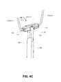
- a graft 330 can be passed through the loop graft retainer element and doubled back - as shown in FIG. 4C .
- a portion 318 of the length of suture material 310 extends across the transverse passage 120 and over the graft retainer element 320 - as shown in FIG. 4B . This reduces the risk that the graft retainer element 320 can be dislodged, particularly while tension is maintained on the leading length 314.
- the fixation device 100 can be drawn end on in the direction of the leading edge - as shown in FIG. 4D .
- the device By applying tension to the trailing length 314 of the suture loop 310, the device can be rotated flat, and the suture loop can be extracted from the device - as shown in FIG. 4E .
- FIG. 5A through FIG. 5F show method steps for using an embodiment fixation device (for example fixation device 100) configured for retaining a graft during an anterior cruciate ligament (“ACL”) reconstruction.
- fixation device 100 for example fixation device 100
- ACL anterior cruciate ligament
- FIG 5A through FIG. 5F shows the femur 510 and tibia 520 are first drilled to form a femoral tunnel 512 and tibial tunnel 522 respectively.
- the femoral tunnel 512 and tibial tunnel 522 can have a single diameter (typically about 7-10mm in diameter) throughout their respective length.
- a first end of the graft 330 is coupled to the fixation device, for example using a graft retainer element 320; and a loop (for example a loop of suture material 310) is coupling the fixation device 100, wherein a stop 316 on the loop abutting a first end of the fixation device.
- FIG. 5A shows tension applied to a leading length 314 of the loop causes the fixation device to draw the graft up through the tunnel.
- FIG. 5B shows tension applied to a leading length 314 of the loop to cause the fixation device to exit the tunnel 522.
- FIG. 5C, FIG. 5D and FIG. 5E shows that, by applying tension to the leading edge 314 and a trailing length 312 of the loop, the fixation device 100 is rotated flat across the tunnel 522.
- FIG. 5F shows that by applying tension to the trailing length 312 of the loop enables extraction of the loop 310 from the fixation device 100, leaving the fixation device located proximal to and across the tunnel 522 - thereby to retain the graft relative to the fixation device and the bone.
- the device is drawn through the tunnel in an end-on configuration (e.g. as shown in FIG. 4D and FIG. 5A ).
- the second aperture is located on the second end of the device proximal to a central longitudinal axis. Travel of the device through the bone tunnel is substantial parallel to the central longitudinal axis. It will be further appreciated that this preferred trajectory can be enhanced by locating the first aperture (e.g. 132) on the second end of the device proximal to a central longitudinal axis.
- suture loop represents a preferred element, and can alternatively comprise any strand element or filament element being suitable for medical procedures and having sufficient length and strength to draw the device in use through a bone tunnel.
- An embodiment method 600 depicted in FIG. 6 , is taught for using a fixation device 100 for drawing a graft 330 through a first tunnel (e.g. 522) defined in a first bone (e.g. 520).
- the method comprising the steps of:
- a suture is used pulls the device up the tunnel using a knot or expansion at abutting the device. Once the graft is in place the surgeon can keep tension on the suture and rotate/flip the device so it is sitting transversely across a bone aperture. The suture can then be removed by pulling it in the opposite direction.
- an embodiment fixation device can have the form 700.
- the fixation device 700 comprises:
- the first aperture 732 and second aperture 734 defines respective ends of the transverse passage 730 that is not fully enclosed.
- the first aperture and the second aperture can be located proximal to the centre of the respective first end and second end.
- the longitudinal through passage 730 extends from the first aperture 732 to a first intermediate aperture 733 proximal to the transverse passage 720, and from a second intermediate aperture 735 proximal to the transverse passage 720 to the second aperture 734.
- the longitudinal through passage exits at the first intermediate aperture 733 and the second intermediate aperture 733 located on the upper surface 716 of the device.
- the longitudinal through passage 730 is defined by a first passage segment 736 and a second passage segment 738, wherein the first passage segment is a substantially straight inwardly-upwardly through-passage extending from the first end 712, and wherein the second passage segment is a substantially straight inwardly-upwardly through-passage extending from the second end 714.
- the longitudinal through passage can be defined in a plurality of configurations wherein the passage comprises a first aperture 732 and a second aperture 734 defined proximal to respective ends of the device.
- the longitudinal through passage can be axially directed.
- transverse passage 722 is necked down to resist release of an inserted graft retainer element (not shown).
- the fixation device 700 can have:
- the body 710 in plan view (e.g. FIG. 8A ) is rectangular having fully rounded edges.
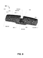
- an embodiment fixation device can have the form 900.
- the fixation device 900 comprises:
- the first aperture 932 and second aperture 934 defines respective ends of the transverse passage 930 that is not fully enclosed.
- the first aperture and the second aperture can be located proximal to the centre of the respective first end and second end.
- the longitudinal through passage 930 extends from the first aperture 932 to a first intermediate aperture 933 proximal to the transverse passage 920, and from a second intermediate aperture 935 proximal to the transverse passage 920 to the second aperture 934.
- the longitudinal through passage exits at the first intermediate aperture 933 and the second intermediate aperture 933 located in cavity defined by the transverse passage 920 of the device.
- the longitudinal through passage 930 is defined by a first passage segment 936 and a second passage segment 938, wherein the first passage segment is a substantially straight inwardly-upwardly through-passage extending from the first end 912, and wherein the second passage segment is a substantially straight inwardly-upwardly through-passage extending from the second end 914.
- each passage segment 936, 938 is inwardly-upwardly directed at an angle of 12 to 15 degrees, and having a bore diameter of about 1mm.
- first passage segment and the second passage segment of the longitudinal through passage have an aperture located within the surface defining the transverse passage.
- the longitudinal through passage can be defined in a plurality of configurations wherein the passage comprises a first aperture 932 and a second aperture 934 defined proximal to respective ends of the device.
- the longitudinal through passage can be axially directed.
- the transverse passage 920 is necked down 922 to define a substantially oval passage 924 for resisting release of an inserted graft retainer element (not shown). It will ne appreciated that the substantially oval profile 924 of the transverse passage 920 enables the graft retainer to move toward one end when the device is drawn end-on though a bone passage.
- the body 910 in plan view (e.g. FIG. 8A ) is rectangular having fully rounded edges, and a convex upper surface. It will be appreciated that the edges and corners of the device are curved to minimise risk of the device cutting or gouging, or becoming caught or snagged during use.
- the illustrated device can retain a graft located with a bone tunnel.
- the graft is a ligament or tendon being either a transplant or artificial.
- the device can be used during surgery (in particular knee surgery) when replacing a tendon or ligament.
- transverse passage that is symmetric and slightly longitudinally extended, for example such that is necked down to define a more oval passage, it reduces the risk that of incorrect orientation (e.g. longitudinal-direction) of the device during use - and which enables the stop (or knot) to be proximal to either end during preliminary configuration of the device.
- the device may be sided (i.e. a smaller version), such that during use a smaller tunnel is first drilled through the outer femoral cortex and then a larger tunnel is drilled not all the way through the cortex.
- This configuration can be (but is not limited to) a substantially similar length to the previously disclosed devices (for example about 12mm) but having an overall diameter of about 4.5 mm.
- any one of the terms comprising, comprised of or which comprises is an open term that means including at least the elements/features that follow, but not excluding others.
- the term comprising, when used in the claims should not be interpreted as being limitative to the means or elements or steps listed thereafter.
- the scope of the expression a device comprising A and B should not be limited to devices consisting only of elements A and B.
- Any one of the terms including or which includes or that includes as used herein is also an open term that also means including at least the elements/features that follow the term, but not excluding others. Thus, including is synonymous with and means comprising.
- Coupled should not be interpreted as being limitative to direct connections only.
- the terms “coupled” and “connected”, along with their derivatives, may be used. It should be understood that these terms are not intended as synonyms for each other.
- the scope of the expression a device A coupled to a device B should not be limited to devices or systems wherein an output of device A is directly connected to an input of device B. It means that there exists a path between an output of A and an input of B which may be a path including other devices or means.
- Coupled may mean that two or more elements are either in direct physical, or that two or more elements are not in direct contact with each other but yet still co-operate or interact with each other.
- an embodiment of the invention can consist essentially of features disclosed herein.
- an embodiment of the invention can consist of features disclosed herein.
- the invention illustratively disclosed herein suitably may be practiced in the absence of any element which is not specifically disclosed herein.
Abstract
Description
- The present invention relates to retaining and fixation devices and in particular to devices for retaining or fastening grafts.
- The invention has been developed primarily for use as a fixation device that can be used to retain or fasten a graft (including tendon or ligament) with respect to a bone and will be described hereinafter with reference to this application. However, it will be appreciated that the invention is not limited to this particular field of use.
- Any discussion of the prior art throughout the specification should in no way be considered as an admission that such prior art is widely known or forms part of the common general knowledge in the field.
- The present disclosure will be used with reference to an anterior cruciate ligament ("ACL") reconstruction, but it will be understood that the technology and methods of the present invention may have other applications for reconstruction of other parts of body
- The ACL reconstruction can be performed in numerous ways. All common methods involve drilling holes or tunnels in the femur and tibia. These can be drilled using a variety of techniques. Grafts such as autografts, allografts or artificial biomaterials may be used to extend between the femoral tunnel and the tibial tunnel. The graft is then fixed to the appropriate bone structure, again numerous techniques being suitable. The replacement graft is fixed to the femur and tibia, most commonly by a screw into the adjacent bone, it being understood that staples, pins and similar devices may also be used.
- A known device for retaining a graft proximal to the aperture to a femoral tunnel is an EndoButton™, as described in: United States Patent No.
6533802 (issued 18 March 2003 ). Similar devices are taught in United States Patent No.5,645,588 (issued 8 July 1997 ) and United States Patent No.5,306,301 (issued 26 April 1994 ). - The EndoButton™ includes an integrally formed continuous ring of polyester tape for fixation of soft tissue. The EndoButton can be drawn through the femoral tunnel through manipulation of a pair of suture loops each taken about and through one of respective pair of through apertures located at the ends of the device. When the device exits the through the femoral tunnel the pair of suture loops are manipulated to lay the device flat across the aperture to the femoral tunnel. Use of the EndoButton requires both pairs of suture loops to be manipulated and appropriately tensioned.
- It is an object of the present invention to overcome or ameliorate at least one of the disadvantages of the prior art, or to provide a useful alternative.
- It is an object of the invention in its preferred form to provide a graft fixation device for retaining graft located with a bone tunnel.
- According to an aspect of the invention there is provided a graft fixation device comprising:
- an elongate body having a first end and a second end;
- a transverse passage for retaining a graft retainer element;
- a first aperture located in the first end, and a second aperture in the second end; the first aperture and second aperture defining respective ends of a longitudinal through passage.
- Preferably, the body has a lower protruding portion located below the transverse passage. More preferably, the lower protruding portion is a smooth bulged portion that extends at least the longitudinal span of the transverse passage.
- Preferably, the transverse passage is defined as a channel being open to an upper surface of the device. More preferably, a lower portion of the channel extends toward the first end. Most preferably, the channel has an hook or 'L' shaped profile. Alternatively, transverse through passage can be symmetric in profile. Alternatively, the transverse through passage can be defined by a closed through aperture (being asymmetric or symmetric).
- Preferably, the body tapers-down toward the second end; More preferably, the body tapers down toward the first end. Most preferably, the body tapers down from a central region toward both the first end and second end.
- Preferably, the graft retainer element is a closed loop element adapted to be located in the transverse passage for retaining the graft with respect to the device. More preferably, the loop is a continuous woven material. Alternatively, the loop is integrally formed with an artificial graft.
- Preferably, the first aperture and the second aperture is located proximal to the centre of the respective first end and second end. Preferably, the longitudinal through passage is sized to receive a length of suture.
- Preferably, the longitudinal through passage extends from the first aperture to a first intermediate aperture proximal to the transverse passage, and from a second intermediate aperture proximal to the transverse passage to the second aperture. More preferably, the longitudinal through passage is intersected by the transverse passage. Most preferably, the longitudinal through passage is defined by a first passage segment and a second passage segment, each passage segment being substantially straight inwardly-upwardly through-passages extending from a respective first end and second end. Alternatively, the longitudinal through passage can be axially directed.
- According to an aspect of the invention there is provided a method of using a fixation device for drawing a graft through a first tunnel defined in a first bone, the method comprising the steps of:
- (a) providing a fixation device;
- (b) coupling the fixation device to a loop having a stop abutting a first end of the fixation device;
- (c) coupling the fixation device to a first end of the graft;
- (d) applying tension to a leading length of the loop to cause the fixation device to draw the graft up through the tunnel;
- (e) applying tension to a leading length of the loop to cause the fixation device to exit the tunnel;
- (f) applying tension to the leading edge and a trailing length of the loop to cause the fixation device to rotate flat across the tunnel; and
- (g) applying tension to the trailing length of the loop to thereby extract the loop from the fixation device.
- According to an aspect of the invention there is provided a method of using a fixation device for drawing a graft through a first tunnel defined in a first bone, the method comprising the steps of:
- (a) providing a fixation device;
- (b) coupling the fixation device to a length of suture having a stop abutting a first end of the fixation device;
- (c) coupling the fixation device to a first end of the graft;
- (d) applying tension to a leading portion of the length of suture to cause the fixation device to draw the graft up through the tunnel;
- (e) applying tension to a leading portion of the length of suture to cause the fixation device to exit the tunnel;
- (f) applying tension to the leading edge and a trailing portion of the length of suture to cause the fixation device to rotate flat across the tunnel; and
- (g) applying tension to the trailing portion of the length of suture to thereby extract the length of suture from the fixation device.
- Preferably, the device is used during knee surgery when replacing a tendon or ligament.
- Preferably, the graft is a ligament or tendon being either a transplant or artificial.
- A preferred embodiment of the invention will now be described, by way of example only, with reference to the accompanying drawings in which:
-
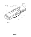
FIG. 1 is a perspective view of an embodiment fixation device according to the invention; -
FIG. 2A is a side view of the device ofFIG. 1 ; -
FIG. 2B is a plan view of the device ofFIG. 1 ; -
FIG. 2C is an end view of the device ofFIG. 1 ; -
FIG. 2D is a sectional side view of the device taken along line D-D ofFIG. 2C ; -
FIG. 2E is a sectional end view of the device taken along line E-E ofFIG. 2B ; -
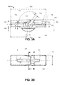
FIG. 3A is a side view of an embodiment fixation device according to the invention; -
FIG. 3B is a plan view of the device ofFIG. 3A ; -
FIG. 3C is an end view of the device ofFIG. 3A ; -
FIG. 3D is a sectional side view of the device taken along line D-D ofFIG. 3C ; -
FIG. 3E is a sectional end view of the device taken along line E-E ofFIG. 3B ; -
FIG. 4A is a perspective view of an embodiment fixation device according to the invention, shown configured with a suture loop and a graft fixation loop; -
FIG. 4B is a sectional side view of the device ofFIG. 4A ; -
FIG. 4C is a perspective view of the device ofFIG. 4A , shown with a joined graft; -
FIG. 4D is a perspective view of the device ofFIG. 4C , shown in a configuration for drawing through a femoral tunnel; -
FIG. 4E is a perspective view of the device ofFIG. 4C , shown with the suture loop removed; -
FIG. 5A-5F are perspective views illustrating steps involved in utilisation of the invention in conjunction with an ACL reconstruction; and -
FIG. 6 shows a flowchart for an embodiment method of using a fixation device according to the invention; -
FIG. 7 is a perspective view of an embodiment fixation device according to the invention; -
FIG. 8A is a side view of the device ofFIG. 7 ; -
FIG. 8B is a plan view of the device ofFIG. 7 ; -
FIG. 8C is an end view of the device ofFIG. 7 ; -
FIG. 9 is a perspective view of an embodiment fixation device according to the invention; -
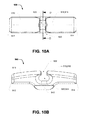
FIG. 10A is a plan view of the device ofFIG. 9 ; -
FIG. 10B is a side view of the device ofFIG. 9 ; -
FIG. 10C is an end view of the device ofFIG. 9 ; -
FIG. 10D is a sectional end view of the device taken along line D-D ofFIG. 10A ; and -
FIG. 10E is a sectional side view of the device taken along line E-E ofFIG. 10C . - Referring initially to
FIG 1 of the drawings, andFIG. 2A to FIG. 2E , anembodiment fixation device 100, by way of example only, can comprise: - an
elongate body 110 having afirst end 112 and asecond end 114; - a
transverse passage 120 for retaining a graft retainer element (not shown); - a longitudinal through passage 130 having a first aperture 132 located in the first end, and a second aperture 134 in the second end.
- The first aperture 132 and second aperture 134 define respective ends of the transverse passage 130. The longitudinal through passage is typically sized to receive a length of suture. Typically, the first aperture and the second aperture can be located proximal to the centre of the respective first end and second end.
- By way of example only, the longitudinal through passage 130 extends from the first aperture 132 to a first intermediate aperture 133 proximal to the transverse passage, and from a second intermediate aperture 135 proximal to the transverse passage to the second aperture 134. In this embodiment, the longitudinal through passage is intersected by the transverse passage. As best shown in
FIG. 2D , the longitudinal through passage 130 is defined by a first passage segment 136 and a second passage segment 138, wherein the first passage segment is a substantially straight inwardly-upwardly through-passage extending from thefirst end 112, and wherein the second passage segment is a substantially straight inwardly-upwardly through-passage extending from thesecond end 114. It will be appreciated that, the longitudinal through passage can be defined in a plurality of configurations wherein the passage comprises a first aperture 132 and a second aperture 134 defined proximal to respective ends of the device. For example, in an embodiment, the longitudinal through passage can be axially directed. - In this embodiment, the body has a lower protruding
portion 140 located below thetransverse passage 120. The lower protruding portion is defined by a smooth bulged portion that extends at least the longitudinal span of the transverse passage. It will be appreciated that the protuberance can provide longitudinal rigidity across the transverse passage, and can assist in locating the device about the tibial through passage. - In accordance with the present example embodiment, the
transverse passage 120 can be defined as a channel that is open to an upper surface of the device. The lower portion of the channel can extend (referring to reference 122) toward the first end. It will be appreciated that, by way of example only, the channel can be an angled slot, or have a hook or 'L' shaped profile. Alternatively, a transverse through passage can be defined a closed through aperture - wherein a graft retainer element is manufactured in situ with the device. An open channel can be necked down to resist release of an inserted graft retainer element. - The body tapers down from a
central region 115 toward both thefirst end 112 andsecond end 114. This can assist movement of the device through a bone tunnel. The graft retainer element is typically, but not limited to, a closed loop element adapted to be located within the transverse passage. By way of example, the graft retainer element can be a loop of continuous woven material. - The graft retainer element can be used for retaining the graft with respect to the device, or alternatively can be a loop that is integrally formed with an artificial graft. It will be appreciated that, by having an open channel, a closed loop can be located after manufacture of the device. Alternatively, the loop can be manufactured in situ (or integrally formed with) the device.
- By way of example, a graft retainer element can be a loop of fibre material (for example suture material), which can be placed over (or through) the transverse passage. The graft can then be retained by passing it through the loop.
- It will be appreciated that the device can be used during knee surgery for fixation of a graft, wherein the graft can include a ligament or tendon being either a transplant or artificial. All references to a graft includes a transplant or artificial tendon and/or ligament.
- By way of example an artificial graft can be combined from multiple artificial tendon strands that are braided to form a graft retainer element in situ.
- It is noted that edges of the device have been rounded to avoid sharp edges, for example: about the exterior of the device; and about or within the passages.
- In an embodiment, by way of an example only, a
fixation device 200 can have dimensions as defined with reference toFIG. 3A through FIG. 3E . - Accordingly, referring to
FIG. 3A through FIG. 3E , afixation device 200 can have: - ➢ an
overall length 202 of about 20mm; - ➢ an
overall height 204 of about 5.5 mm; - ➢ an
overall width 206 of about 5.5 mm; - ➢ a lower protruding
portion height 208 of about 1.8mm; - ➢ a transverse passage having a
slot width 210 of about 1mm aninclination 212 of about 125 degrees; a lower portion of the passage extends 214 about 1 mm having a height 216 of about 1.6mm, having a concave terminus having a radius 218 of about 0.8mm; - ➢ a longitudinal through passage having
nominal bore diameter 220 of about 1.35mm, a first passage segment and a second passage segment each inclined 222 at about 15 degrees; an intermediate open segment of the passage extending 224 about 11mm; and - ➢ the body has an
overall diameter 230, about thelongitudinal axis 231, of about 5.5 mm; and the body tapers down from a central toward both the first end having a height 332 of about 3.2mm and second end having aheight 234 of about 2.7mm. - Depending on the size of the device (thereby imparting a structural strength) and the intended use of the device, it will be appreciated that the device can be manufactured from materials including (but not limited to) any one or more of the materials selected from the set comprising: metals (such a titanium), metal alloys (such as stainless steels, cobalt-chromium alloys, and titanium alloys), metal composites, ceramics, polymers or plastics (such as polyethylene) and carbon fibre.
-
FIG. 4A through FIG. 4E show anembodiment fixation device 100 configured for retaining a graft. - In this configuration, a length of suture material 310 is threaded through the device to define a loop having a trailing length 312 and a leading length 314. The suture material loop having a stop 316 which abuts the
first end 112 of the fixation device. In this embodiment, thestop 316 is a knot formed at an intermediate position of the suture material 310. It will be appreciated that the stop can be associated with the suture material 310, including any one of the following methods selected from the set: applied to, integrally formed with, interconnected with, or attached to. - In this configuration a
graft retainer element 320 is located within (and retained by) thetransverse passage 120. The graft retainer element is by way of example only a loop graft retainer element. By way of example, agraft 330 can be passed through the loop graft retainer element and doubled back - as shown inFIG. 4C . - It will be appreciated that a portion 318 of the length of suture material 310, extends across the
transverse passage 120 and over the graft retainer element 320 - as shown inFIG. 4B . This reduces the risk that thegraft retainer element 320 can be dislodged, particularly while tension is maintained on the leading length 314. - In use, by applying tension to a leading length 314 of the suture loop 310, the
fixation device 100 can be drawn end on in the direction of the leading edge - as shown inFIG. 4D . By applying tension to the trailing length 314 of the suture loop 310, the device can be rotated flat, and the suture loop can be extracted from the device - as shown inFIG. 4E . -
FIG. 5A through FIG. 5F show method steps for using an embodiment fixation device (for example fixation device 100) configured for retaining a graft during an anterior cruciate ligament ("ACL") reconstruction. -
FIG 5A through FIG. 5F shows thefemur 510 andtibia 520 are first drilled to form afemoral tunnel 512 andtibial tunnel 522 respectively. In this example, it is noted that thefemoral tunnel 512 andtibial tunnel 522 can have a single diameter (typically about 7-10mm in diameter) throughout their respective length. - Upon providing a
fixation device 100; a first end of thegraft 330 is coupled to the fixation device, for example using agraft retainer element 320; and a loop (for example a loop of suture material 310) is coupling thefixation device 100, wherein astop 316 on the loop abutting a first end of the fixation device. -
FIG. 5A shows tension applied to a leading length 314 of the loop causes the fixation device to draw the graft up through the tunnel. -
FIG. 5B shows tension applied to a leading length 314 of the loop to cause the fixation device to exit thetunnel 522. -
FIG. 5C, FIG. 5D andFIG. 5E shows that, by applying tension to the leading edge 314 and a trailing length 312 of the loop, thefixation device 100 is rotated flat across thetunnel 522. -
FIG. 5F shows that by applying tension to the trailing length 312 of the loop enables extraction of the loop 310 from thefixation device 100, leaving the fixation device located proximal to and across the tunnel 522 - thereby to retain the graft relative to the fixation device and the bone. - It will be appreciated that by locating the second aperture (e.g. 134) on the
second end 114, and by applying tension to the leading length 314 of the suture loop, the device is drawn through the tunnel in an end-on configuration (e.g. as shown inFIG. 4D andFIG. 5A ). Typically the second aperture is located on the second end of the device proximal to a central longitudinal axis. Travel of the device through the bone tunnel is substantial parallel to the central longitudinal axis. It will be further appreciated that this preferred trajectory can be enhanced by locating the first aperture (e.g. 132) on the second end of the device proximal to a central longitudinal axis. - It will be appreciated that reference to a suture loop represents a preferred element, and can alternatively comprise any strand element or filament element being suitable for medical procedures and having sufficient length and strength to draw the device in use through a bone tunnel.
- An
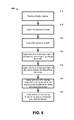
embodiment method 600, depicted inFIG. 6 , is taught for using afixation device 100 for drawing agraft 330 through a first tunnel (e.g. 522) defined in a first bone (e.g. 520). The method comprising the steps of: - STEP 610: providing a
fixation device 100; - STEP 620: coupling the
fixation device 100 to a loop (for example a loop of suture material 310) having astop 316 abutting a first end of the fixation device; - STEP 630: coupling the fixation device to a first end of the
graft 330, for example using agraft retainer element 320; - STEP 640: applying tension to a leading length 314 of the loop to cause the fixation device to draw the graft up through the tunnel - as shown in
FIG. 5A ; - STEP 650: applying tension to a leading length 314 of the loop to cause the fixation device to exit the tunnel 522- as shown in
FIG. 5B ; - STEP 660: applying tension to the leading edge 314 and a trailing length 312 of the loop to cause the
fixation device 100 to rotate flat across the tunnel 522 - as shown inFIG. 5C, FIG. 5D andFIG. 5E ; and - STEP 670: applying tension to the trailing length 312 of the loop to thereby extract the loop 310 from the
fixation device 100, as shown inFIG. 5F . - A suture is used pulls the device up the tunnel using a knot or expansion at abutting the device. Once the graft is in place the surgeon can keep tension on the suture and rotate/flip the device so it is sitting transversely across a bone aperture. The suture can then be removed by pulling it in the opposite direction.
- It will be appreciated by those skilled in the art that other embodied may have many other forms.
- Referring to
FIG. 7 andFIG. 8A throughFIG. 8C , by way of example only, an embodiment fixation device can have theform 700. In this embodiment, thefixation device 700, comprises: - an
elongate body 710 having afirst end 712 and asecond end 714; - a
transverse passage 720 for retaining a graft retainer element (not shown); - a longitudinal through passage 730 having a first aperture 732 located in the first end, and a second aperture 734 in the second end.
- The first aperture 732 and second aperture 734 defines respective ends of the transverse passage 730 that is not fully enclosed. Typically, the first aperture and the second aperture can be located proximal to the centre of the respective first end and second end.
- By way of example only, the longitudinal through passage 730 extends from the first aperture 732 to a first intermediate aperture 733 proximal to the
transverse passage 720, and from a second intermediate aperture 735 proximal to thetransverse passage 720 to the second aperture 734. In this embodiment, the longitudinal through passage exits at the first intermediate aperture 733 and the second intermediate aperture 733 located on theupper surface 716 of the device. - As best shown in
FIG. 8B , the longitudinal through passage 730 is defined by a first passage segment 736 and a second passage segment 738, wherein the first passage segment is a substantially straight inwardly-upwardly through-passage extending from thefirst end 712, and wherein the second passage segment is a substantially straight inwardly-upwardly through-passage extending from thesecond end 714. - It will be appreciated that, the longitudinal through passage can be defined in a plurality of configurations wherein the passage comprises a first aperture 732 and a second aperture 734 defined proximal to respective ends of the device. For example, in an embodiment, the longitudinal through passage can be axially directed.
- In this example, the
transverse passage 722 is necked down to resist release of an inserted graft retainer element (not shown). - Referring to
FIG. 8A through FIG. 8C , thefixation device 700 can have: - ➢ an
overall length 802 of about 20 mm; - ➢ an
overall height 804 of about 5 mm; - ➢ an
overall width 206 of about 5 mm; - ➢ a lower protruding
portion height 208 of about 1.5 mm; - ➢ a transverse passage having a
necked slot width 810 of about 1mm; adepth 812 of about 1.5mm; wherein a lower portion of the passage having adiameter 814 of about 1.6mm; - ➢ a longitudinal through passage having nominal bore diameter 820 of about 1.2mm, a first passage segment and a second passage segment each inclined 822 at about 12 degrees.
- In this example embodiment, in plan view (e.g.
FIG. 8A ) thebody 710 is rectangular having fully rounded edges. - Referring to
FIG. 9 andFIG. 10A throughFIG. 10E , by way of example only, an embodiment fixation device can have theform 900. In this embodiment, thefixation device 900, comprises: - an
elongate body 910 having afirst end 912 and asecond end 914; - a
transverse passage 920 for retaining a graft retainer element (not shown); - a longitudinal through passage 930 having a first aperture 932 located in the first end, and a second aperture 934 in the second end.
- The first aperture 932 and second aperture 934 defines respective ends of the transverse passage 930 that is not fully enclosed. Typically, the first aperture and the second aperture can be located proximal to the centre of the respective first end and second end.
- By way of example only, the longitudinal through passage 930 extends from the first aperture 932 to a first intermediate aperture 933 proximal to the
transverse passage 920, and from a second intermediate aperture 935 proximal to thetransverse passage 920 to the second aperture 934. In this embodiment, the longitudinal through passage exits at the first intermediate aperture 933 and the second intermediate aperture 933 located in cavity defined by thetransverse passage 920 of the device. - As best shown in
FIG. 10E , the longitudinal through passage 930 is defined by afirst passage segment 936 and asecond passage segment 938, wherein the first passage segment is a substantially straight inwardly-upwardly through-passage extending from thefirst end 912, and wherein the second passage segment is a substantially straight inwardly-upwardly through-passage extending from thesecond end 914. In this embodiment, eachpassage segment - In this example embodiment, the first passage segment and the second passage segment of the longitudinal through passage have an aperture located within the surface defining the transverse passage.
- It will be appreciated that, the longitudinal through passage can be defined in a plurality of configurations wherein the passage comprises a first aperture 932 and a second aperture 934 defined proximal to respective ends of the device. For example, in an embodiment, the longitudinal through passage can be axially directed.
- In this example, the
transverse passage 920 is necked down 922 to define a substantially oval passage 924 for resisting release of an inserted graft retainer element (not shown). It will ne appreciated that the substantially oval profile 924 of thetransverse passage 920 enables the graft retainer to move toward one end when the device is drawn end-on though a bone passage. - In this example embodiment, in plan view (e.g.
FIG. 8A ) thebody 910 is rectangular having fully rounded edges, and a convex upper surface. It will be appreciated that the edges and corners of the device are curved to minimise risk of the device cutting or gouging, or becoming caught or snagged during use. - It will be appreciated that the illustrated device can retain a graft located with a bone tunnel. The graft is a ligament or tendon being either a transplant or artificial. The device can be used during surgery (in particular knee surgery) when replacing a tendon or ligament.
- It will be further appreciated that by including a the transverse passage that is symmetric and slightly longitudinally extended, for example such that is necked down to define a more oval passage, it reduces the risk that of incorrect orientation (e.g. longitudinal-direction) of the device during use - and which enables the stop (or knot) to be proximal to either end during preliminary configuration of the device.
- It will be further appreciated that the device may be sided (i.e. a smaller version), such that during use a smaller tunnel is first drilled through the outer femoral cortex and then a larger tunnel is drilled not all the way through the cortex. This configuration can be (but is not limited to) a substantially similar length to the previously disclosed devices (for example about 12mm) but having an overall diameter of about 4.5 mm.
- Although the invention has been described with reference to specific examples, it will be appreciated by those skilled in the art that the invention may be embodied in many other forms.
- Reference throughout this specification to "one embodiment" or "an embodiment" means that a particular feature, structure or characteristic described in connection with the embodiment is included in at least one embodiment of the present invention. Thus, appearances of the phrases "in one embodiment" or "in an embodiment" in various places throughout this specification are not necessarily all referring to the same embodiment, but may. Furthermore, the particular features, structures or characteristics may be combined in any suitable manner, as would be apparent to one of ordinary skill in the art from this disclosure, in one or more embodiments.
- In the claims below and the description herein, any one of the terms comprising, comprised of or which comprises is an open term that means including at least the elements/features that follow, but not excluding others. Thus, the term comprising, when used in the claims, should not be interpreted as being limitative to the means or elements or steps listed thereafter. For example, the scope of the expression a device comprising A and B should not be limited to devices consisting only of elements A and B. Any one of the terms including or which includes or that includes as used herein is also an open term that also means including at least the elements/features that follow the term, but not excluding others. Thus, including is synonymous with and means comprising.
- Similarly, it is to be noticed that the term coupled, when used in the claims, should not be interpreted as being limitative to direct connections only. The terms "coupled" and "connected", along with their derivatives, may be used. It should be understood that these terms are not intended as synonyms for each other. Thus, the scope of the expression a device A coupled to a device B should not be limited to devices or systems wherein an output of device A is directly connected to an input of device B. It means that there exists a path between an output of A and an input of B which may be a path including other devices or means. "Coupled" may mean that two or more elements are either in direct physical, or that two or more elements are not in direct contact with each other but yet still co-operate or interact with each other.
- As used herein, unless otherwise specified the use of the ordinal adjectives "first", "second", "third", etc., to describe a common object, merely indicate that different instances of like objects are being referred to, and are not intended to imply that the objects so described must be in a given sequence, either temporally, spatially, in ranking, or in any other manner.
- As used herein, unless otherwise specified the use of terms "horizontal", "vertical", "left", "right", "up" and "down", as well as adjectival and adverbial derivatives thereof (e.g., "horizontally", "rightwardly", "upwardly", etc.), simply refer to the orientation of the illustrated structure as the particular drawing figure faces the reader, or with reference to the orientation of the structure during nominal use, as appropriate. Similarly, the terms "inwardly" and "outwardly" generally refer to the orientation of a surface relative to its axis of elongation, or axis of rotation, as appropriate.
- Similarly it should be appreciated that in the above description of exemplary embodiments of the invention, various features of the invention are sometimes grouped together in a single embodiment, figure, or description thereof for the purpose of streamlining the disclosure and aiding in the understanding of one or more of the various inventive aspects. This method of disclosure, however, is not to be interpreted as reflecting an intention that the claimed invention requires more features than are expressly recited in each claim. Rather, as the following claims reflect, inventive aspects lie in less than all features of a single foregoing disclosed embodiment. Thus, the claims following the Detailed Description are hereby expressly incorporated into this Detailed Description, with each claim standing on its own as a separate embodiment of this invention.
- Furthermore, while some embodiments described herein include some but not other features included in other embodiments, combinations of features of different embodiments are meant to be within the scope of the invention, and form different embodiments, as would be understood by those in the art. For example, in the following claims, any of the claimed embodiments can be used in any combination.
- In the description provided herein, numerous specific details are set forth. However, it is understood that embodiments of the invention may be practiced without these specific details. In other instances, well-known methods, structures and techniques have not been shown in detail in order not to obscure an understanding of this description.
- Thus, while there has been described what are believed to be the preferred embodiments of the invention, those skilled in the art will recognize that other and further modifications may be made thereto without departing from the spirit of the invention, and it is intended to claim all such changes and modifications as fall within the scope of the invention. For example, any formulas given above are merely representative of procedures that may be used. Functionality may be added or deleted from the block diagrams and operations may be interchanged among functional blocks. Steps may be added or deleted to methods described within the scope of the present invention.
- It will be appreciated that an embodiment of the invention can consist essentially of features disclosed herein. Alternatively, an embodiment of the invention can consist of features disclosed herein. The invention illustratively disclosed herein suitably may be practiced in the absence of any element which is not specifically disclosed herein.
Claims (15)
- A fixation device for a graft, the device including:an elongate body having a first end and a second end;a transverse passage for retaining a graft retainer element;a first aperture located in the first end, and a second aperture in the second end;the first aperture and second aperture defining respective ends of a longitudinal through path.
- The device according to claim 1, wherein the body has a lower protruding portion located below the transverse passage.
- The device according to claim 2, wherein the lower protruding portion is a transverse smooth bulged portion with a width that extends at least the longitudinal span of the transverse passage.
- The device according to any one of claims 1 to 3, wherein the transverse passage is defined as a channel being open to an upper surface of the device.
- The device according to claim 4, wherein a lower portion of the channel extends toward the first end.
- The device according to claim 5, wherein the channel has an hook or 'L' shaped profile.
- The device according to any one of claims 1 to 3, wherein the transverse passage is by a closed through aperture.
- The device according to any one of claims 1 to 7, wherein the body tapers-down toward the second end.
- The device according to any one of claims 1 to 8, wherein the body tapers down from a central region toward both the first end and the second end.
- The device according to any one of claims 1 to 9, the device further including the graft retainer element in the form of a closed loop element located in the transverse passage for retaining the graft with respect to the device.
- The device according to any one of claims 1 to 10, wherein the first aperture and the second aperture are located proximal to the centre of the respective first end and second end; and the longitudinal through path is sized to receive a length of suture.
- The device according to any one of claims 1 to 11, wherein the longitudinal through path is intersected by the transverse passage.
- The device according to claim 12, wherein the longitudinal through path extends from the first aperture to a first intermediate aperture proximal to the transverse passage, and from a second intermediate aperture proximal to the transverse passage to the second aperture.
- The device according to claim 13, wherein the longitudinal through path is defined by a first passage segment and a second passage segment, each passage segment being substantially straight inwardly-upwardly through-passages extending from a respective first end and second end.
- The device according to any one of claims 1 to 11, wherein the longitudinal through path is an axially directed through passage.
Applications Claiming Priority (1)
| Application Number | Priority Date | Filing Date | Title |
|---|---|---|---|
| AU2012902627A AU2012902627A0 (en) | 2012-06-22 | Improved Ligament Fixation Device |
Publications (3)
| Publication Number | Publication Date |
|---|---|
| EP2676613A2 true EP2676613A2 (en) | 2013-12-25 |
| EP2676613A3 EP2676613A3 (en) | 2014-01-08 |
| EP2676613B1 EP2676613B1 (en) | 2017-11-29 |
Family
ID=49003631
Family Applications (1)
| Application Number | Title | Priority Date | Filing Date |
|---|---|---|---|
| EP13173203.4A Active EP2676613B1 (en) | 2012-06-22 | 2013-06-21 | Improved graft fixation device |
Country Status (5)
| Country | Link |
|---|---|
| US (1) | US9186241B2 (en) |
| EP (1) | EP2676613B1 (en) |
| JP (1) | JP6420028B2 (en) |
| AU (1) | AU2013206414B2 (en) |
| ES (1) | ES2659993T3 (en) |
Cited By (2)
| Publication number | Priority date | Publication date | Assignee | Title |
|---|---|---|---|---|
| WO2021101724A1 (en) * | 2019-11-22 | 2021-05-27 | Smith & Nephew, Inc. | Surgical fixation devices and methods of use thereof |
| EP4248912A1 (en) * | 2022-03-21 | 2023-09-27 | Inion Oy | Graft suspension device and arrangement |
Families Citing this family (8)
| Publication number | Priority date | Publication date | Assignee | Title |
|---|---|---|---|---|
| US9265600B2 (en) * | 2013-02-27 | 2016-02-23 | Orthopediatrics Corp. | Graft fixation |
| US9974643B2 (en) * | 2013-03-11 | 2018-05-22 | Medos International Sàrl | Implant having adjustable filament coils |
| US9387065B2 (en) * | 2014-03-28 | 2016-07-12 | Medos International Sàrl | Implant and filament management device |
| BR102015007027B1 (en) | 2014-03-28 | 2022-02-08 | Medos International Sàrl | IMPLANT AND FILAMENT MANAGEMENT DEVICE |
| JP6450004B2 (en) | 2014-11-25 | 2019-01-09 | ジョナサン ピー.ガリ−ノ | Cruciate ligament replacement knee prosthesis |
| AU2016364969B2 (en) | 2015-12-04 | 2021-09-16 | Crossroads Extremity Systems, Llc | Devices for anchoring tissue |
| US20220104935A1 (en) * | 2020-10-05 | 2022-04-07 | Biomet Manufacturing, Llc | Devices and methods for fixation against tissue |
| US11389290B1 (en) * | 2021-04-08 | 2022-07-19 | Integrity Orthopaedics, Inc. | Delivery device for implanting knotless micro-suture anchors and anchor arrays for attachment of soft tissue to bone |
Citations (2)
| Publication number | Priority date | Publication date | Assignee | Title |
|---|---|---|---|---|
| US5306301A (en) | 1993-02-11 | 1994-04-26 | American Cyanamid Company | Graft attachment device and method of using same |
| US6533802B2 (en) | 2001-05-16 | 2003-03-18 | Smith & Nephew, Inc. | Endobutton continuous loop for bone-tendon-bone |
Family Cites Families (20)
| Publication number | Priority date | Publication date | Assignee | Title |
|---|---|---|---|---|
| US5464427A (en) * | 1994-10-04 | 1995-11-07 | Synthes (U.S.A.) | Expanding suture anchor |
| US6117161A (en) * | 1995-06-06 | 2000-09-12 | Li Medical Tecnologies, Inc. | Fastener and fastening method, particularly for fastening sutures to bone |
| GB9524861D0 (en) | 1995-12-05 | 1996-02-07 | United Surgical Services Ltd | Surgical anchorage |
| GB9620046D0 (en) * | 1996-09-26 | 1996-11-13 | Neoligaments | Attachment device for use in the implantation of prosthetic ligament |
| EP1482841B1 (en) * | 2002-03-14 | 2005-12-07 | Yeung, Jeffery E. | Suture anchor and approximating device |
| US7338492B2 (en) * | 2002-05-15 | 2008-03-04 | Linvatec Corporation | Cross-pin graft fixation, instruments, and methods |
| US7722644B2 (en) * | 2003-06-11 | 2010-05-25 | Medicine Lodge, Inc. | Compact line locks and methods |
| US8062334B2 (en) * | 2004-06-02 | 2011-11-22 | Kfx Medical Corporation | Suture anchor |
| US8109965B2 (en) * | 2004-06-09 | 2012-02-07 | Biomet Sports Medicine, LLP | Method and apparatus for soft tissue fixation |
| US7582105B2 (en) * | 2004-06-30 | 2009-09-01 | Silhouette Lift Societad Limitada | Suture for wound closure, tissue approximation, tissue support, suspension and/or fixation |
| US8323338B2 (en) * | 2005-12-22 | 2012-12-04 | Smith & Nephew, Inc. | Tissue graft fixation |
| WO2007109665A1 (en) | 2006-03-20 | 2007-09-27 | Smith & Nephew, Inc. | Tissue graft fixation |
| US8852250B2 (en) | 2006-05-18 | 2014-10-07 | Linvatec Corporation | Graft fixation implant |
| US8226714B2 (en) * | 2006-09-29 | 2012-07-24 | Depuy Mitek, Inc. | Femoral fixation |
| US9364276B2 (en) * | 2009-07-09 | 2016-06-14 | Smith & Nephew, Inc | Tissue graft anchor assembly and instrumentation for use therewith |
| US9179905B2 (en) * | 2009-07-17 | 2015-11-10 | Pivot Medical, Inc. | Method and apparatus for re-attaching the labrum to the acetabulum, including the provision and use of a novel suture anchor system |
| WO2012040627A1 (en) * | 2010-09-24 | 2012-03-29 | Medicinelodge, Inc. Dba Imds Co-Innovation | System for intra -operative tension and fixation of zipknot acl fixation |
| US8790352B2 (en) * | 2011-10-03 | 2014-07-29 | Smith & Nephew, Inc. | Ovoid tunnel guide and method of ACL reconstruction |
| US8545558B2 (en) | 2012-02-02 | 2013-10-01 | Depuy Mitek, Llc | Flipping-type graft fixation device and method |
| US9056003B2 (en) * | 2013-01-25 | 2015-06-16 | Smith & Nephew, Inc. | Tissue graft fixation |
-
2013
- 2013-06-19 US US13/921,208 patent/US9186241B2/en not_active Expired - Fee Related
- 2013-06-19 AU AU2013206414A patent/AU2013206414B2/en active Active
- 2013-06-21 JP JP2013130282A patent/JP6420028B2/en active Active
- 2013-06-21 ES ES13173203.4T patent/ES2659993T3/en active Active
- 2013-06-21 EP EP13173203.4A patent/EP2676613B1/en active Active
Patent Citations (3)
| Publication number | Priority date | Publication date | Assignee | Title |
|---|---|---|---|---|
| US5306301A (en) | 1993-02-11 | 1994-04-26 | American Cyanamid Company | Graft attachment device and method of using same |
| US5645588A (en) | 1993-02-11 | 1997-07-08 | Acufex Microsurgical, Inc. | Graft attachment device |
| US6533802B2 (en) | 2001-05-16 | 2003-03-18 | Smith & Nephew, Inc. | Endobutton continuous loop for bone-tendon-bone |
Cited By (2)
| Publication number | Priority date | Publication date | Assignee | Title |
|---|---|---|---|---|
| WO2021101724A1 (en) * | 2019-11-22 | 2021-05-27 | Smith & Nephew, Inc. | Surgical fixation devices and methods of use thereof |
| EP4248912A1 (en) * | 2022-03-21 | 2023-09-27 | Inion Oy | Graft suspension device and arrangement |
Also Published As
| Publication number | Publication date |
|---|---|
| US20140094912A1 (en) | 2014-04-03 |
| JP2014004363A (en) | 2014-01-16 |
| AU2013206414B2 (en) | 2018-11-01 |
| ES2659993T3 (en) | 2018-03-20 |
| AU2013206414A1 (en) | 2014-01-16 |
| EP2676613A3 (en) | 2014-01-08 |
| US9186241B2 (en) | 2015-11-17 |
| JP6420028B2 (en) | 2018-11-07 |
| EP2676613B1 (en) | 2017-11-29 |
Similar Documents
| Publication | Publication Date | Title |
|---|---|---|
| AU2013206414B2 (en) | Improved Graft Fixation Device | |
| US9539085B2 (en) | Double-loop endobutton, ovoid tunnel guide, and method of ACL re-construction using the ovoid tunnel guide and the double-loop endobutton | |
| US8852250B2 (en) | Graft fixation implant | |
| EP3463185B1 (en) | Loop/ button system for tendon and ligament reconstruction | |
| JP5882337B2 (en) | Tissue fixture | |
| US11395727B2 (en) | Graft preparation system | |
| JP6949853B2 (en) | Graft suspension device | |
| EP3797706B1 (en) | One-way adjustable loop suture constructs | |
| EP2760373B1 (en) | Attachment device to attach tissue graft | |
| US20190125518A1 (en) | Whip-Stitching With Reinforcement Material | |
| EP2809268B1 (en) | Implantable biologic holder | |
| US20230248357A1 (en) | Implant and suture organization device | |
| JP2019500912A (en) | Flexible wire intraosseous attachment system configured to secure ligament tissue to bone | |
| US20210068815A1 (en) | Coined suture passing drill | |
| KR20210102322A (en) | Self-Drilling Anchor Inserter |
Legal Events
| Date | Code | Title | Description |
|---|---|---|---|
| PUAL | Search report despatched |
Free format text: ORIGINAL CODE: 0009013 |
|
| PUAI | Public reference made under article 153(3) epc to a published international application that has entered the european phase |
Free format text: ORIGINAL CODE: 0009012 |
|
| AK | Designated contracting states |
Kind code of ref document: A2 Designated state(s): AL AT BE BG CH CY CZ DE DK EE ES FI FR GB GR HR HU IE IS IT LI LT LU LV MC MK MT NL NO PL PT RO RS SE SI SK SM TR |
|
| AX | Request for extension of the european patent |
Extension state: BA ME |
|
| AK | Designated contracting states |
Kind code of ref document: A3 Designated state(s): AL AT BE BG CH CY CZ DE DK EE ES FI FR GB GR HR HU IE IS IT LI LT LU LV MC MK MT NL NO PL PT RO RS SE SI SK SM TR |
|
| AX | Request for extension of the european patent |
Extension state: BA ME |
|
| RIC1 | Information provided on ipc code assigned before grant |
Ipc: A61B 17/04 20060101AFI20131204BHEP |
|
| 17P | Request for examination filed |
Effective date: 20140708 |
|
| RBV | Designated contracting states (corrected) |
Designated state(s): AL AT BE BG CH CY CZ DE DK EE ES FI FR GB GR HR HU IE IS IT LI LT LU LV MC MK MT NL NO PL PT RO RS SE SI SK SM TR |
|
| 17Q | First examination report despatched |
Effective date: 20150212 |
|
| RIC1 | Information provided on ipc code assigned before grant |
Ipc: A61F 2/08 20060101ALI20151029BHEP Ipc: A61B 17/04 20060101AFI20151029BHEP |
|
| GRAP | Despatch of communication of intention to grant a patent |
Free format text: ORIGINAL CODE: EPIDOSNIGR1 |
|
| INTG | Intention to grant announced |
Effective date: 20170608 |
|
| GRAS | Grant fee paid |
Free format text: ORIGINAL CODE: EPIDOSNIGR3 |
|
| GRAA | (expected) grant |
Free format text: ORIGINAL CODE: 0009210 |
|
| AK | Designated contracting states |
Kind code of ref document: B1 Designated state(s): AL AT BE BG CH CY CZ DE DK EE ES FI FR GB GR HR HU IE IS IT LI LT LU LV MC MK MT NL NO PL PT RO RS SE SI SK SM TR |
|
| REG | Reference to a national code |
Ref country code: CH Ref legal event code: EP |
|
| REG | Reference to a national code |
Ref country code: AT Ref legal event code: REF Ref document number: 949644 Country of ref document: AT Kind code of ref document: T Effective date: 20171215 |
|
| REG | Reference to a national code |
Ref country code: IE Ref legal event code: FG4D |
|
| REG | Reference to a national code |
Ref country code: DE Ref legal event code: R096 Ref document number: 602013030020 Country of ref document: DE |
|
| REG | Reference to a national code |
Ref country code: CH Ref legal event code: NV Representative=s name: ISLER AND PEDRAZZINI AG, CH |
|
| REG | Reference to a national code |
Ref country code: ES Ref legal event code: FG2A Ref document number: 2659993 Country of ref document: ES Kind code of ref document: T3 Effective date: 20180320 |
|
| REG | Reference to a national code |
Ref country code: NL Ref legal event code: MP Effective date: 20171129 |
|
| REG | Reference to a national code |
Ref country code: LT Ref legal event code: MG4D |
|
| REG | Reference to a national code |
Ref country code: AT Ref legal event code: MK05 Ref document number: 949644 Country of ref document: AT Kind code of ref document: T Effective date: 20171129 |
|
| PG25 | Lapsed in a contracting state [announced via postgrant information from national office to epo] |
Ref country code: FI Free format text: LAPSE BECAUSE OF FAILURE TO SUBMIT A TRANSLATION OF THE DESCRIPTION OR TO PAY THE FEE WITHIN THE PRESCRIBED TIME-LIMIT Effective date: 20171129 Ref country code: LT Free format text: LAPSE BECAUSE OF FAILURE TO SUBMIT A TRANSLATION OF THE DESCRIPTION OR TO PAY THE FEE WITHIN THE PRESCRIBED TIME-LIMIT Effective date: 20171129 Ref country code: SE Free format text: LAPSE BECAUSE OF FAILURE TO SUBMIT A TRANSLATION OF THE DESCRIPTION OR TO PAY THE FEE WITHIN THE PRESCRIBED TIME-LIMIT Effective date: 20171129 Ref country code: NO Free format text: LAPSE BECAUSE OF FAILURE TO SUBMIT A TRANSLATION OF THE DESCRIPTION OR TO PAY THE FEE WITHIN THE PRESCRIBED TIME-LIMIT Effective date: 20180228 |
|
| PG25 | Lapsed in a contracting state [announced via postgrant information from national office to epo] |
Ref country code: AT Free format text: LAPSE BECAUSE OF FAILURE TO SUBMIT A TRANSLATION OF THE DESCRIPTION OR TO PAY THE FEE WITHIN THE PRESCRIBED TIME-LIMIT Effective date: 20171129 Ref country code: LV Free format text: LAPSE BECAUSE OF FAILURE TO SUBMIT A TRANSLATION OF THE DESCRIPTION OR TO PAY THE FEE WITHIN THE PRESCRIBED TIME-LIMIT Effective date: 20171129 Ref country code: HR Free format text: LAPSE BECAUSE OF FAILURE TO SUBMIT A TRANSLATION OF THE DESCRIPTION OR TO PAY THE FEE WITHIN THE PRESCRIBED TIME-LIMIT Effective date: 20171129 Ref country code: RS Free format text: LAPSE BECAUSE OF FAILURE TO SUBMIT A TRANSLATION OF THE DESCRIPTION OR TO PAY THE FEE WITHIN THE PRESCRIBED TIME-LIMIT Effective date: 20171129 Ref country code: GR Free format text: LAPSE BECAUSE OF FAILURE TO SUBMIT A TRANSLATION OF THE DESCRIPTION OR TO PAY THE FEE WITHIN THE PRESCRIBED TIME-LIMIT Effective date: 20180301 Ref country code: BG Free format text: LAPSE BECAUSE OF FAILURE TO SUBMIT A TRANSLATION OF THE DESCRIPTION OR TO PAY THE FEE WITHIN THE PRESCRIBED TIME-LIMIT Effective date: 20180228 |
|
| REG | Reference to a national code |
Ref country code: FR Ref legal event code: PLFP Year of fee payment: 6 |
|
| PG25 | Lapsed in a contracting state [announced via postgrant information from national office to epo] |
Ref country code: NL Free format text: LAPSE BECAUSE OF FAILURE TO SUBMIT A TRANSLATION OF THE DESCRIPTION OR TO PAY THE FEE WITHIN THE PRESCRIBED TIME-LIMIT Effective date: 20171129 |
|
| PG25 | Lapsed in a contracting state [announced via postgrant information from national office to epo] |
Ref country code: SK Free format text: LAPSE BECAUSE OF FAILURE TO SUBMIT A TRANSLATION OF THE DESCRIPTION OR TO PAY THE FEE WITHIN THE PRESCRIBED TIME-LIMIT Effective date: 20171129 Ref country code: CZ Free format text: LAPSE BECAUSE OF FAILURE TO SUBMIT A TRANSLATION OF THE DESCRIPTION OR TO PAY THE FEE WITHIN THE PRESCRIBED TIME-LIMIT Effective date: 20171129 Ref country code: CY Free format text: LAPSE BECAUSE OF FAILURE TO SUBMIT A TRANSLATION OF THE DESCRIPTION OR TO PAY THE FEE WITHIN THE PRESCRIBED TIME-LIMIT Effective date: 20171129 Ref country code: DK Free format text: LAPSE BECAUSE OF FAILURE TO SUBMIT A TRANSLATION OF THE DESCRIPTION OR TO PAY THE FEE WITHIN THE PRESCRIBED TIME-LIMIT Effective date: 20171129 Ref country code: EE Free format text: LAPSE BECAUSE OF FAILURE TO SUBMIT A TRANSLATION OF THE DESCRIPTION OR TO PAY THE FEE WITHIN THE PRESCRIBED TIME-LIMIT Effective date: 20171129 |
|
| REG | Reference to a national code |
Ref country code: DE Ref legal event code: R097 Ref document number: 602013030020 Country of ref document: DE |
|
| PG25 | Lapsed in a contracting state [announced via postgrant information from national office to epo] |
Ref country code: PL Free format text: LAPSE BECAUSE OF FAILURE TO SUBMIT A TRANSLATION OF THE DESCRIPTION OR TO PAY THE FEE WITHIN THE PRESCRIBED TIME-LIMIT Effective date: 20171129 Ref country code: RO Free format text: LAPSE BECAUSE OF FAILURE TO SUBMIT A TRANSLATION OF THE DESCRIPTION OR TO PAY THE FEE WITHIN THE PRESCRIBED TIME-LIMIT Effective date: 20171129 Ref country code: SM Free format text: LAPSE BECAUSE OF FAILURE TO SUBMIT A TRANSLATION OF THE DESCRIPTION OR TO PAY THE FEE WITHIN THE PRESCRIBED TIME-LIMIT Effective date: 20171129 |
|
| PLBE | No opposition filed within time limit |
Free format text: ORIGINAL CODE: 0009261 |
|
| STAA | Information on the status of an ep patent application or granted ep patent |
Free format text: STATUS: NO OPPOSITION FILED WITHIN TIME LIMIT |
|
| 26N | No opposition filed |
Effective date: 20180830 |
|
| PG25 | Lapsed in a contracting state [announced via postgrant information from national office to epo] |
Ref country code: SI Free format text: LAPSE BECAUSE OF FAILURE TO SUBMIT A TRANSLATION OF THE DESCRIPTION OR TO PAY THE FEE WITHIN THE PRESCRIBED TIME-LIMIT Effective date: 20171129 |
|
| REG | Reference to a national code |
Ref country code: BE Ref legal event code: MM Effective date: 20180630 |
|
| REG | Reference to a national code |
Ref country code: IE Ref legal event code: MM4A |
|
| PG25 | Lapsed in a contracting state [announced via postgrant information from national office to epo] |
Ref country code: LU Free format text: LAPSE BECAUSE OF NON-PAYMENT OF DUE FEES Effective date: 20180621 Ref country code: MC Free format text: LAPSE BECAUSE OF FAILURE TO SUBMIT A TRANSLATION OF THE DESCRIPTION OR TO PAY THE FEE WITHIN THE PRESCRIBED TIME-LIMIT Effective date: 20171129 |
|
| PG25 | Lapsed in a contracting state [announced via postgrant information from national office to epo] |
Ref country code: IE Free format text: LAPSE BECAUSE OF NON-PAYMENT OF DUE FEES Effective date: 20180621 |
|
| PG25 | Lapsed in a contracting state [announced via postgrant information from national office to epo] |
Ref country code: BE Free format text: LAPSE BECAUSE OF NON-PAYMENT OF DUE FEES Effective date: 20180630 |
|
| PG25 | Lapsed in a contracting state [announced via postgrant information from national office to epo] |
Ref country code: MT Free format text: LAPSE BECAUSE OF NON-PAYMENT OF DUE FEES Effective date: 20180621 |
|
| PG25 | Lapsed in a contracting state [announced via postgrant information from national office to epo] |
Ref country code: TR Free format text: LAPSE BECAUSE OF FAILURE TO SUBMIT A TRANSLATION OF THE DESCRIPTION OR TO PAY THE FEE WITHIN THE PRESCRIBED TIME-LIMIT Effective date: 20171129 |
|
| PG25 | Lapsed in a contracting state [announced via postgrant information from national office to epo] |
Ref country code: PT Free format text: LAPSE BECAUSE OF FAILURE TO SUBMIT A TRANSLATION OF THE DESCRIPTION OR TO PAY THE FEE WITHIN THE PRESCRIBED TIME-LIMIT Effective date: 20171129 Ref country code: HU Free format text: LAPSE BECAUSE OF FAILURE TO SUBMIT A TRANSLATION OF THE DESCRIPTION OR TO PAY THE FEE WITHIN THE PRESCRIBED TIME-LIMIT; INVALID AB INITIO Effective date: 20130621 |
|
| PG25 | Lapsed in a contracting state [announced via postgrant information from national office to epo] |
Ref country code: MK Free format text: LAPSE BECAUSE OF NON-PAYMENT OF DUE FEES Effective date: 20171129 |
|
| PG25 | Lapsed in a contracting state [announced via postgrant information from national office to epo] |
Ref country code: AL Free format text: LAPSE BECAUSE OF FAILURE TO SUBMIT A TRANSLATION OF THE DESCRIPTION OR TO PAY THE FEE WITHIN THE PRESCRIBED TIME-LIMIT Effective date: 20171129 Ref country code: IS Free format text: LAPSE BECAUSE OF FAILURE TO SUBMIT A TRANSLATION OF THE DESCRIPTION OR TO PAY THE FEE WITHIN THE PRESCRIBED TIME-LIMIT Effective date: 20180329 |
|
| REG | Reference to a national code |
Ref country code: DE Ref legal event code: R081 Ref document number: 602013030020 Country of ref document: DE Owner name: MEDACTA INTERNATIONAL S.A., CH Free format text: FORMER OWNER: WALKER, PETER MICHAEL SUTHERLAND, BELLEVUE HILL, AU |
|
| REG | Reference to a national code |
Ref country code: ES Ref legal event code: PC2A Owner name: MEDACTA INTERNATIONAL, S.A. Effective date: 20220711 |
|
| PGFP | Annual fee paid to national office [announced via postgrant information from national office to epo] |
Ref country code: GB Payment date: 20220630 Year of fee payment: 10 |
|
| REG | Reference to a national code |
Ref country code: GB Ref legal event code: 732E Free format text: REGISTERED BETWEEN 20220721 AND 20220727 |
|
| PGFP | Annual fee paid to national office [announced via postgrant information from national office to epo] |
Ref country code: IT Payment date: 20220630 Year of fee payment: 10 Ref country code: ES Payment date: 20220711 Year of fee payment: 10 Ref country code: DE Payment date: 20220630 Year of fee payment: 10 |
|
| PGFP | Annual fee paid to national office [announced via postgrant information from national office to epo] |
Ref country code: FR Payment date: 20220719 Year of fee payment: 10 |
|
| PGFP | Annual fee paid to national office [announced via postgrant information from national office to epo] |
Ref country code: CH Payment date: 20220713 Year of fee payment: 10 |
|
| REG | Reference to a national code |
Ref country code: DE Ref legal event code: R119 Ref document number: 602013030020 Country of ref document: DE |
|
| REG | Reference to a national code |
Ref country code: CH Ref legal event code: PL |
|
| GBPC | Gb: european patent ceased through non-payment of renewal fee |
Effective date: 20230621 |