EP2674190A1 - Elektrodenstruktur für eine multipolare Detektions-/Stimulationsmikrosonde zur Implantation in ein Herz- oder Hirngefäß - Google Patents
Elektrodenstruktur für eine multipolare Detektions-/Stimulationsmikrosonde zur Implantation in ein Herz- oder Hirngefäß Download PDFInfo
- Publication number
- EP2674190A1 EP2674190A1 EP12194864.0A EP12194864A EP2674190A1 EP 2674190 A1 EP2674190 A1 EP 2674190A1 EP 12194864 A EP12194864 A EP 12194864A EP 2674190 A1 EP2674190 A1 EP 2674190A1
- Authority
- EP
- European Patent Office
- Prior art keywords
- probe
- ring
- microcable
- connection
- electrode
- Prior art date
- Legal status (The legal status is an assumption and is not a legal conclusion. Google has not performed a legal analysis and makes no representation as to the accuracy of the status listed.)
- Granted
Links
- 238000002513 implantation Methods 0.000 title 1
- 239000004020 conductor Substances 0.000 claims abstract description 31
- 230000000638 stimulation Effects 0.000 claims abstract description 24
- 238000001514 detection method Methods 0.000 claims abstract description 12
- 239000000523 sample Substances 0.000 claims description 74
- 229910052751 metal Inorganic materials 0.000 claims description 20
- 239000002184 metal Substances 0.000 claims description 20
- 239000000463 material Substances 0.000 claims description 14
- 230000001926 lymphatic effect Effects 0.000 claims description 8
- 229920002635 polyurethane Polymers 0.000 claims description 8
- 239000004814 polyurethane Substances 0.000 claims description 8
- 238000009413 insulation Methods 0.000 claims description 7
- 239000003292 glue Substances 0.000 claims description 4
- 239000007787 solid Substances 0.000 claims description 4
- 230000004936 stimulating effect Effects 0.000 claims description 4
- 239000011810 insulating material Substances 0.000 claims description 3
- 239000002861 polymer material Substances 0.000 claims description 3
- 230000001681 protective effect Effects 0.000 claims description 3
- 238000000034 method Methods 0.000 description 10
- 230000008901 benefit Effects 0.000 description 9
- 238000002788 crimping Methods 0.000 description 8
- 239000011248 coating agent Substances 0.000 description 6
- 238000000576 coating method Methods 0.000 description 6
- BASFCYQUMIYNBI-UHFFFAOYSA-N platinum Chemical compound [Pt] BASFCYQUMIYNBI-UHFFFAOYSA-N 0.000 description 6
- 230000007797 corrosion Effects 0.000 description 5
- 238000005260 corrosion Methods 0.000 description 5
- 230000000694 effects Effects 0.000 description 5
- 239000010410 layer Substances 0.000 description 5
- 230000005405 multipole Effects 0.000 description 5
- OKTJSMMVPCPJKN-UHFFFAOYSA-N Carbon Chemical compound [C] OKTJSMMVPCPJKN-UHFFFAOYSA-N 0.000 description 4
- 239000004952 Polyamide Substances 0.000 description 4
- 229910052799 carbon Inorganic materials 0.000 description 4
- 206010016256 fatigue Diseases 0.000 description 4
- 229920002313 fluoropolymer Polymers 0.000 description 4
- 239000004811 fluoropolymer Substances 0.000 description 4
- 229920002647 polyamide Polymers 0.000 description 4
- 229920000728 polyester Polymers 0.000 description 4
- 238000007789 sealing Methods 0.000 description 4
- 239000004696 Poly ether ether ketone Substances 0.000 description 3
- 239000004642 Polyimide Substances 0.000 description 3
- 239000000853 adhesive Substances 0.000 description 3
- 230000001070 adhesive effect Effects 0.000 description 3
- 229910045601 alloy Inorganic materials 0.000 description 3
- 239000000956 alloy Substances 0.000 description 3
- 230000003872 anastomosis Effects 0.000 description 3
- 210000001124 body fluid Anatomy 0.000 description 3
- 239000010839 body fluid Substances 0.000 description 3
- 238000005516 engineering process Methods 0.000 description 3
- 229920000840 ethylene tetrafluoroethylene copolymer Polymers 0.000 description 3
- 238000002955 isolation Methods 0.000 description 3
- 230000007774 longterm Effects 0.000 description 3
- 238000004519 manufacturing process Methods 0.000 description 3
- 229910001000 nickel titanium Inorganic materials 0.000 description 3
- 229920000052 poly(p-xylylene) Polymers 0.000 description 3
- 229920002530 polyetherether ketone Polymers 0.000 description 3
- 229920001721 polyimide Polymers 0.000 description 3
- 238000011282 treatment Methods 0.000 description 3
- 235000008612 Gnetum gnemon Nutrition 0.000 description 2
- 240000000018 Gnetum gnemon Species 0.000 description 2
- KDLHZDBZIXYQEI-UHFFFAOYSA-N Palladium Chemical compound [Pd] KDLHZDBZIXYQEI-UHFFFAOYSA-N 0.000 description 2
- 238000013459 approach Methods 0.000 description 2
- 230000005540 biological transmission Effects 0.000 description 2
- 230000000747 cardiac effect Effects 0.000 description 2
- 230000002490 cerebral effect Effects 0.000 description 2
- 210000000080 chela (arthropods) Anatomy 0.000 description 2
- 229910052804 chromium Inorganic materials 0.000 description 2
- 238000000605 extraction Methods 0.000 description 2
- 238000010438 heat treatment Methods 0.000 description 2
- 230000000004 hemodynamic effect Effects 0.000 description 2
- 239000007943 implant Substances 0.000 description 2
- 230000008595 infiltration Effects 0.000 description 2
- 238000001764 infiltration Methods 0.000 description 2
- 239000010445 mica Substances 0.000 description 2
- 229910052618 mica group Inorganic materials 0.000 description 2
- 229910052750 molybdenum Inorganic materials 0.000 description 2
- 229910052759 nickel Inorganic materials 0.000 description 2
- 229910052697 platinum Inorganic materials 0.000 description 2
- HWLDNSXPUQTBOD-UHFFFAOYSA-N platinum-iridium alloy Chemical compound [Ir].[Pt] HWLDNSXPUQTBOD-UHFFFAOYSA-N 0.000 description 2
- 229920003229 poly(methyl methacrylate) Polymers 0.000 description 2
- 239000004417 polycarbonate Substances 0.000 description 2
- 229920000515 polycarbonate Polymers 0.000 description 2
- 239000004926 polymethyl methacrylate Substances 0.000 description 2
- 229920001343 polytetrafluoroethylene Polymers 0.000 description 2
- 239000004810 polytetrafluoroethylene Substances 0.000 description 2
- 230000009467 reduction Effects 0.000 description 2
- 238000013519 translation Methods 0.000 description 2
- 230000002861 ventricular Effects 0.000 description 2
- BQCIDUSAKPWEOX-UHFFFAOYSA-N 1,1-Difluoroethene Chemical compound FC(F)=C BQCIDUSAKPWEOX-UHFFFAOYSA-N 0.000 description 1
- 208000012902 Nervous system disease Diseases 0.000 description 1
- 208000025966 Neurological disease Diseases 0.000 description 1
- 239000002033 PVDF binder Substances 0.000 description 1
- 208000018737 Parkinson disease Diseases 0.000 description 1
- 229920001774 Perfluoroether Polymers 0.000 description 1
- NRTOMJZYCJJWKI-UHFFFAOYSA-N Titanium nitride Chemical compound [Ti]#N NRTOMJZYCJJWKI-UHFFFAOYSA-N 0.000 description 1
- 238000002679 ablation Methods 0.000 description 1
- 230000009471 action Effects 0.000 description 1
- 230000004888 barrier function Effects 0.000 description 1
- 238000010009 beating Methods 0.000 description 1
- 238000005452 bending Methods 0.000 description 1
- 230000015572 biosynthetic process Effects 0.000 description 1
- 239000008280 blood Substances 0.000 description 1
- 210000004369 blood Anatomy 0.000 description 1
- 210000004556 brain Anatomy 0.000 description 1
- 238000005234 chemical deposition Methods 0.000 description 1
- 229920006026 co-polymeric resin Polymers 0.000 description 1
- 150000001875 compounds Chemical class 0.000 description 1
- 239000012141 concentrate Substances 0.000 description 1
- 210000003748 coronary sinus Anatomy 0.000 description 1
- 210000004351 coronary vessel Anatomy 0.000 description 1
- 238000009792 diffusion process Methods 0.000 description 1
- 208000037265 diseases, disorders, signs and symptoms Diseases 0.000 description 1
- 208000035475 disorder Diseases 0.000 description 1
- 238000006073 displacement reaction Methods 0.000 description 1
- 230000005684 electric field Effects 0.000 description 1
- 238000010292 electrical insulation Methods 0.000 description 1
- 229940082150 encore Drugs 0.000 description 1
- 206010015037 epilepsy Diseases 0.000 description 1
- QHSJIZLJUFMIFP-UHFFFAOYSA-N ethene;1,1,2,2-tetrafluoroethene Chemical group C=C.FC(F)=C(F)F QHSJIZLJUFMIFP-UHFFFAOYSA-N 0.000 description 1
- 208000028327 extreme fatigue Diseases 0.000 description 1
- 239000012530 fluid Substances 0.000 description 1
- HCDGVLDPFQMKDK-UHFFFAOYSA-N hexafluoropropylene Chemical group FC(F)=C(F)C(F)(F)F HCDGVLDPFQMKDK-UHFFFAOYSA-N 0.000 description 1
- 238000001802 infusion Methods 0.000 description 1
- 239000012212 insulator Substances 0.000 description 1
- 230000010354 integration Effects 0.000 description 1
- 229910052741 iridium Inorganic materials 0.000 description 1
- GKOZUEZYRPOHIO-UHFFFAOYSA-N iridium atom Chemical compound [Ir] GKOZUEZYRPOHIO-UHFFFAOYSA-N 0.000 description 1
- 238000000608 laser ablation Methods 0.000 description 1
- 238000012423 maintenance Methods 0.000 description 1
- 230000004007 neuromodulation Effects 0.000 description 1
- 229910000510 noble metal Inorganic materials 0.000 description 1
- 210000000056 organ Anatomy 0.000 description 1
- 229910052763 palladium Inorganic materials 0.000 description 1
- 210000003105 phrenic nerve Anatomy 0.000 description 1
- 238000009832 plasma treatment Methods 0.000 description 1
- -1 polytetrafluoroethylene Polymers 0.000 description 1
- 238000003825 pressing Methods 0.000 description 1
- 230000008569 process Effects 0.000 description 1
- 125000004805 propylene group Chemical group [H]C([H])([H])C([H])([*:1])C([H])([H])[*:2] 0.000 description 1
- 230000008672 reprogramming Effects 0.000 description 1
- 239000002356 single layer Substances 0.000 description 1
- 238000004544 sputter deposition Methods 0.000 description 1
- 239000010935 stainless steel Substances 0.000 description 1
- 229910001220 stainless steel Inorganic materials 0.000 description 1
- 239000000126 substance Substances 0.000 description 1
- 229910052715 tantalum Inorganic materials 0.000 description 1
- GUVRBAGPIYLISA-UHFFFAOYSA-N tantalum atom Chemical compound [Ta] GUVRBAGPIYLISA-UHFFFAOYSA-N 0.000 description 1
- BFKJFAAPBSQJPD-UHFFFAOYSA-N tetrafluoroethene Chemical group FC(F)=C(F)F BFKJFAAPBSQJPD-UHFFFAOYSA-N 0.000 description 1
- 230000009466 transformation Effects 0.000 description 1
- 210000003462 vein Anatomy 0.000 description 1
- 210000000264 venule Anatomy 0.000 description 1
- 238000011179 visual inspection Methods 0.000 description 1
Images


Classifications
-
- A—HUMAN NECESSITIES
- A61—MEDICAL OR VETERINARY SCIENCE; HYGIENE
- A61N—ELECTROTHERAPY; MAGNETOTHERAPY; RADIATION THERAPY; ULTRASOUND THERAPY
- A61N1/00—Electrotherapy; Circuits therefor
- A61N1/02—Details
- A61N1/04—Electrodes
- A61N1/05—Electrodes for implantation or insertion into the body, e.g. heart electrode
-
- H—ELECTRICITY
- H01—ELECTRIC ELEMENTS
- H01R—ELECTRICALLY-CONDUCTIVE CONNECTIONS; STRUCTURAL ASSOCIATIONS OF A PLURALITY OF MUTUALLY-INSULATED ELECTRICAL CONNECTING ELEMENTS; COUPLING DEVICES; CURRENT COLLECTORS
- H01R4/00—Electrically-conductive connections between two or more conductive members in direct contact, i.e. touching one another; Means for effecting or maintaining such contact; Electrically-conductive connections having two or more spaced connecting locations for conductors and using contact members penetrating insulation
- H01R4/24—Connections using contact members penetrating or cutting insulation or cable strands
- H01R4/2491—Connections using contact members penetrating or cutting insulation or cable strands the contact members penetrating the insulation being actuated by conductive cams or wedges
-
- A—HUMAN NECESSITIES
- A61—MEDICAL OR VETERINARY SCIENCE; HYGIENE
- A61N—ELECTROTHERAPY; MAGNETOTHERAPY; RADIATION THERAPY; ULTRASOUND THERAPY
- A61N1/00—Electrotherapy; Circuits therefor
- A61N1/02—Details
- A61N1/04—Electrodes
- A61N1/05—Electrodes for implantation or insertion into the body, e.g. heart electrode
- A61N1/056—Transvascular endocardial electrode systems
Definitions
- the invention relates generally to "active implantable medical devices" as defined by Council Directive 90/385 / EEC of 20 June 1990.
- a microprobe of detection / stimulation intended to be implanted in venous, arterial or lymphatic networks in order to deliver an electrical pulse and / or to detect an electrical activity.
- Such a probe can in particular be used in cardiology, in particular to be implanted in the venous network of the coronary sinus in order to stimulate a left or right cavity of the heart.
- Microprobes are, however, useful in many other medical applications, whenever one is in the presence of a venous, arterial or even lymphatic network, such as in particular the venous or arterial cerebral network.
- electrical stimulation has led to significant advances in neurology in the field of neuromodulation, which involves stimulating target areas of the brain for the treatment of disorders such as Parkinson's disease, epilepsy and other neurological diseases.
- Such a technique allows a less invasive approach to these treatments and above all a superior efficacy of the treatments administered.
- the size of the current implantable probes being typically of the order of 4 to 6 French (1.33 to 2 mm), it would be desirable to be able to reduce this diameter to less than 2 French (0.66 mm) to open new perspectives of medical applications in areas that have not been explored so far, given technological constraints.
- Such a micro-microprobe size would make it possible to reach very small venules, inaccessible today with devices of greater size.
- Such a microprobe must also be able to navigate easily in the arterial or lymphatic venous networks by presenting a sufficient flexibility to be able to be introduced in networks of vessels presenting strong tortuosities, anastomoses, etc.
- Probes have been proposed comprising a microcable consisting of a central conductor intended to be connected to the generator of the implant, this conductor being coated with an electrically insulating sheath.
- the central conductor is full, the diameter of the spiral conductors used up to now being incompatible with the required diameter.
- These probes monopolar, also have on their active part one or more electrodes detection / stimulation all electrically connected to the central conductor, and intended to come into contact with the wall of the target vessel.
- a first technique for producing the electrodes of such probes described for example in the EP 2 455 131 A1 (Sorin CRM SAS), consists in punctually stripping the insulating sheath so as to expose the microcable in one or more points. The stripped portions together constitute a network of electrodes connected in series to multiply the stimulation points and thus ensure multizone diffusion of the stimulation energy delivered by the implant.
- This same document also proposes, in a variant, to make the active microprobe part by successively and alternately threading on the microcable insulating tubes and conductive electrodes in iridescent platinum, in the form of rings.
- the insulating tubes for example made of polyurethane, are glued to the microcable and the iridium platinum electrodes are crimped directly onto this microcable.
- Still another technique consists in applying to the microcable a coating of insulating polyurethane glue, leaving locally uncoated, conductive surfaces in reserve.
- a conductive coating for example a titanium nitride alloy or a carbofilm-type carbon deposit. (registered trademark) by a sputtering technique such as that described in particular in the US 5,370,684 A and US 5,387,247 (both in the name of Sorin Biomedica SpA), to protect the exposed cable from corrosion.
- the microcable must be perfectly isolated from any contact with the environment of the microprobe, hence the additional conductive coating of NiTi or carbon on the electrode areas or the crimp on the microcable of platinum rings iridium (noble material, insensitive to corrosion).
- This isolation constraint of the microcable with the external medium, in particular in the region of the electrodes, must be respected i) over the expected lifetime of the microprobe, ie 10 years, and ii) despite all the mechanical stresses that the microprobe is likely to undergo, typically 400 000 000 bending stress without rupture, this figure corresponding to the average number of heartbeats over the lifetime of the microprobe. Compliance with these conditions is essential for the microprobe to be implanted permanently in the body, typically in a coronary vessel.
- a microprobe of stimulation by the venous network can be the seat of deformations under curvatures much higher than those which undergoes a conventional probe, insofar as it must follow the deformations of the veins. This causes greater stress and makes its resistance to fatigue more restrictive.
- the inner face of the ring is in mechanical contact with the surface of the sheath, with interposition of the insulating material of the sheath between the microcable and the ring in regions on either side. the perforation zone of the sheath.
- a multipolar probe in particular to operate a bipolar stimulation by sending pulses between two electrodes located at the end of the probe, or between two electrodes of straight ventricular probes, instead of doing so. between an electrode (or series of electrodes) and the generator box, as with a monopolar probe.
- US 2008/0114230 A1 and US 7,364,479 B1 describe electrode support structures for multipolar probe.
- a multipole detection / stimulation probe intended to be implanted in a venous, arterial or lymphatic network
- this probe comprising, in a manner known per se, in particular according to FIG. US 2008/0114230 A1 mentioned above: at least two microcables each consisting of a solid central conductor intended to be connected to an active implantable medical device generator, and a sheath made of an insulating polymer material surrounding the central conductor on its periphery and on its length ; at least one detection / stimulation electrode intended to be electrically connected to a central conductor of a microcable and to come against a wall of a target vessel of said venous, arterial or lymphatic network; and means of electrical connection between the electrode and a central conductor.
- the outer diameter of the probe is at most equal to 2 French (0.66 mm), and the electrode comprises a cylindrical metal ring having a longitudinal electrical connection slot adapted to receive a microcable intended to be connected to the ring, and at least one longitudinal electrode passage lumen.
- the longitudinal electrode passage lumen is adapted to receive at least one microcable not connected to the ring; and the electrode also comprises means for electrical connection by perforation comprising at least one guide tunnel transverse to the ring, formed between the periphery of the ring and the electrical connection light, and an electrical connection slide able to slide in the guide tunnel and provided with an inner end shaped to perforate the sheath of the microcable in the light so as to make electrical contact between the ring and the central conductor of the microcable via the connection drawer mounted and held tight in the tunnel guidance.
- the probe according to the invention is multipole, it is therefore with a plurality of microcables whose number depends in particular on the number of poles considered, and these microcables are inserted through lights arranged on a plurality of metal rings arranged on along the probe and forming electrodes.
- Each ring comprises a connection light receiving the microcable whose central conductor must be electrically connected to the ring and other microcables, which must not be connected to the ring, through the latter simply by the so-called electrode crossing lights.
- connection slide whose forced sliding movement in the guide tunnel causes the perforation of the insulating sheath of the microcable through the internal end of the drawer .
- the technique of electrical connection by perforation guarantees the tightness around the microcables and their protection against electrocorrosion, without the need to use special means of NiTi conductive coating type or carbon.
- the physical continuity of microcables is ensured and gives the entire probe excellent mechanical strength even under high curvature, for example the crossing of vessels with high tortuosity and anastomoses.
- the slide axis of the connection slide passes through the center of the connecting lumen. It is also advantageous that the probe of the invention comprises two opposite connection drawers. In addition, in order to avoid formation on the periphery of the metal ring of protuberances which would affect the isodiametric profile of the probe, the connection drawer in the perforation position is completely retracted inside the guide tunnel.
- the electrode feed light receives a plurality of microcables not connected to the ring, for a limited space requirement.
- the probe comprises, at the periphery of the ring, at least one zone of non-through longitudinal grooves. In this way, peak effects are created which generate better transmission of electrical impulses to tissues.
- the invention provides that the latter is covered with a collective outer sheath of heat-shrinkable insulating material, windows being cut in this sheath around detection / stimulation surfaces.
- the ring which in addition can carry longitudinal grooves.
- a flexible adhesive seal may be deposited at the ends of the ring, and a chamfer or a countersink is provided at each end of the ring, in particular to better manage the stiffness gradient ring / body of probe.
- a cylindrical metal ring 10 constituting a detection / stimulation electrode for a multipolar probe which, in the proposed embodiment, has three microcables respectively referenced 21, 22a and 22b (in practice, the number of microcables varies generally between two and four).
- This electrode is intended to be electrically connected to one of the microcables and to come into contact with a wall of a target vessel of the venous, arterial or lymphatic network.
- the ring 10 is made of a material that is insensitive to the phenomenon of electrocorrosion, such as an iridium platinum alloy (typically 90/10) or of another noble metal, such as palladium or tantalum.
- an iridium platinum alloy typically 90/10
- another noble metal such as palladium or tantalum.
- each electrode or group of electrodes being connected to the same pole of the implanted generator, that is to say each ring or group of rings. being connected (s) to a microcable itself connected to the pole, the whole structure forming a single-body type probe.
- the technical difficulty is then to establish an industrialized reliable connection with that of the microcables that constitutes the conduction line, while preserving the isolation of the other unconnected microcables, all to be contained in a diameter of 1 to 2 French (0 , 33 to 0.66 mm) to preserve the benefits of such devices, for example the passage of anastomoses to establish a left ventricular stimulating system via two distinct areas.
- the proposed solution as illustrated on Figures 1a, 1b and 1c , consists in that the cylindrical metal ring 10, of diameter substantially equal to 1 to 2 French (0.33 to 0.66 mm), comprises three longitudinal slots 11, 12a and 12b extending parallel to the axis of the ring 10.
- one of these lights receives the microcable 21 intended to be connected to the ring 10 and to a pole of the generator.
- microcable is normally a non-bare microcable, to benefit the best of all the advantages of the invention, but alternatively it can be stripped locally, the means that will be described are then intended to make the contact directly on the stripped region of the cable without perforation of the insulation.
- the other two longitudinal lumens 12a and 12b are called “electrode feedthroughs” in that they allow the microcables 22a and 22b, which must not be connected to the ring 10, to pass through it.
- connection light 11 has a circular opening of diameter substantially equal to that of the connected microcable 21 (with a minimum set of mounting, related to the dimensional tolerances of the components).
- the electrode feed-through lights 12a and 12b may have a diameter greater than that of the unconnected microcables 22a and 22b, in order to avoid any risk of damage to the microcables insulation in the immediate vicinity of the ring ; this increase in diameter also makes it possible to insert an additional protective insulating sheath (not shown) into the electrode bushings, which also makes it possible, from a mechanical point of view, to contribute to the management of stiffness gradients in the immediate vicinity of the ring.
- the microcables 21, 22a and 22b are formed of a solid central conductor 23 surrounded by a sheath 24 of insulating polymer material.
- the central conductor 23 is advantageously a multi-wire structure in the form of a strand of a plurality of conductive strands 231 of small diameter.
- a strand comprises seven strands 231 of 33 microns in diameter for a total diameter of 100 microns.
- a strand 231 has a bi-material structure, namely a platinum core and a stainless steel envelope made of an alloy of the MP35 N type (35% Ni, 35% Co, 20% Cr and 10% Mo ) or MP35 NLT, whose essential advantage is its extreme fatigue endurance.
- the reduction in diameter of the single strands reduces the stress applied to each of them, and therefore increases the fatigue performance of the strand structure.
- Such a structure, without internal lumen and with several strands twisted together, is able to provide both endurance against cardiac movements and resistance to stresses related to the pose.
- the MP35N can be coated with platinum in order to guarantee complete protection of the electrical junction against electrocorrosion, in case the sealing at the puncture through the insulation, or between the connection slide and the guide tunnel, or even the sealing of the possible bonding, would not be sufficient.
- the insulating sheath 24 As regards the insulating sheath 24, this must satisfy the following characteristics: fatigue resistance, electrical insulation, long-term biocompatibility, biostability, possibility of transformation and compatibility with the central conductor 23.
- the materials that can be used in this context include the materials of the group comprising: polyurethanes (PU), polyesters (PET), polyamides (PA), polycarbonates (PC), polyimides, fluoropolymers, polyether ether-ketone (PEEK), poly-p-xylylene (parylene) and polymethylmethacrylate (PMM).
- PU polyurethanes
- PET polyesters
- PA polyamides
- PC polycarbonates
- PEEK polyether ether-ketone
- parylene poly-p-xylylene
- PMM polymethylmethacrylate
- materials with high chemical inertness such as fluoropolymers, which also have a very good quality of insulation.
- materials of the group comprising: PTFE (polytetrafluoroethylene), FEP (perfluorinated propylene), PFA (perfluoroalkoxy copolymer resin), THV (tetrafluoroethylene, hexafluoropropylene, vinylidene fluoride), PVDF (polyvinylidene fluoride), EFEP (ethylene propylene fluorinated ethylene) and ETFE (ethylene tetrafluoroethylene).
- PTFE polytetrafluoroethylene
- FEP perfluorinated propylene
- PFA perfluoroalkoxy copolymer resin
- THV tetrafluoroethylene, hexafluoropropylene, vinylidene fluoride
- PVDF polyvinylidene fluoride
- EFEP ethylene propylene fluorinated
- the methods for producing the insulating sheath 24 on the central conductor 23 depend on the materials used, for example: coextrusion on the conductor (for PU, PA, PEEK, polyimides and fluoropolymers); dip deposit in a solution (for PU, PA and polyimides); heating of a heat-shrinkable tube (for PET and fluoropolymers); chemical deposition by gas (for parylene); plasma treatments to improve adhesion between layers.
- the invention has been illustrated with a single layer of the same material sheathing the microcables 21, 22a and 22b, it is possible to provide several successive layers forming the sheath 24, for example a layer of PET and a layer of ETFE.
- the insulating sheath 24 has a typical thickness of 5 to 20 microns.
- the electrical connection between the ring 10 and the microcable 21 is made by perforation of the insulating sheath 24 of the microcable by means of two transverse metal connection drawers 14a, 14b, each provided with an internal end 141a, 141b shaped to perforate the microcable sheath 21 present in the connecting light 11, so as to make electrical contact between the ring 10 and the central conductor 23 of the microcable 21 via the drawers 14a, 14b.
- connection drawers comprise an inner end 141a, 141b of projecting shape and can respectively slide in guide tunnels 13a, 13b transverse to the ring 10, arranged between the periphery of the ring and the connection lumen 11.
- connection drawers 14a, 14b in the perforation position are preferably retracted inside the respective guiding tunnels 13a, 13b.
- the effective perforation of the insulating sheath 24 of the microcable 21 to be connected is achieved by pressing force by means of crimping jaws bearing on the surfaces 143a and 143b of the connection drawers 14a, 14b push.
- the system with two opposed connection drawers makes it possible to make the microcable / ring connection reliable, on the one hand, by a pincer effect on the microcable receiving opposite connection pressures and, on the other hand, by redundancy of the contact on the microcable.
- connection drawers 14a, 14b slide in the tunnels 13a, 13b along the same sliding axis AA passing through the center of the connection lumen 11, in order to orient the thrust surfaces 143a, 143b perpendicular to the movement of the crimping jaws.
- An alternative solution is to make parallel the push surfaces of the connection drawers, allowing to use a crimping equipment with parallel and non-concentric jaws.
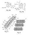
- the Figure 5 shows a multipolar probe element comprising six rings, the first three 10 1 are connected to the same microcable, while the last three 2 2 are connected to another microcable due to a different orientation of the rings.
- the choice of the microcable connected for a given electrode is set by the angular positioning of the ring during pre-assembly of the probe as a whole.
- the angular sequence of stacking of the rings can be encoded on the mounting tool, the keying being obtained because the protrusion region of the connection drawers 14a, 14b must enter in a notch arranged on the tool.
- the alternative solution of the Figure 6 consists in stacking clusters of rings one above the other, the position of each ring 10 on a cluster being determined by the choice of microcable to connect.
- the alignment of the lights allows the simultaneous introduction in a single step of the microcables through all the rings, the latter then being detached from the cluster. It remains to position the rings longitudinally before the crimping operation.
- connection drawers 14a, 14b When the microcables are inserted, the projecting internal ends 141a, 141b of the connection drawers 14a, 14b are completely retracted inside the guiding tunnels 13a, 13b, thus avoiding any difficulty in introducing the microcables as the connection lights 11 are then completely cleared.
- One or more temporary attachment zones are provided in the axial direction for example. These areas are intended to keep the drawers 14a, 14b in the open position during all ring manufacturing operations, control, and assembly of cables to the crimping stage. Under the force of the jaws, the temporary attachment zones are broken and no longer impede the sliding movement of the drawers in the tunnels 13a, 13b.
- the concentric crimping operation does not require angular identification of the assembly.
- a rapid visual inspection of production and / or final control makes it possible to identify the state of the system, namely "connected" state for electrodes without protuberance, or "unconnected” state for electrodes with one or two protuberances.
- a preferred method for producing rings 10 is the MICA Freeform process (registered trademark of Microfabrica, Inc.) for its specificities: extreme precision, integration of components, etc. Thanks to this technology by successive layers, the metal ring 10, the connection drawers 14a, 14b and the zones 144 of temporary attachment form a single piece.
- zones 18a, 18b and 18c on the periphery of the ring 10 are provided on the periphery of the ring.
- Figures 7a and 7b bearing longitudinal grooves 181 flush contained within the surface of the ring. These grooves 181, with a radius of at least 5 ⁇ m, are not through to maintain at each end of the ring 10 a cylindrical perimeter which guarantees the longitudinal sealing function of the electrode when laying a metal. heat-shrinkable collective outer sheath 30 shown in FIGS. Figures 8a, 8b and 8c .
- This collective sheath 30 avoids any discontinuity of global isolation and the creation of local stiffness gradients.
- Windows 31 are cut in the collective sheath 30 by laser ablation around stimulation surfaces, namely here the zones 18a, 18b and 18c of longitudinal grooving. Only these areas of grooving in contact with the tissues are stimulating.
- a metal ring 10 provided at each end of a chamfer 16a, 16b.
- This feature has the advantage of protecting the insulating sheaths 24 of the microcables from an abrasive contact with the outer edge of the ring. Indeed, under the action of the heat-shrinkable sheath 30, the three microcables can be held in position in their respective lumen over a greater length corresponding to the generatrix G of the connection lumen 11 shown on FIG. Figures 2a and 2b .
- These chamfers also make it possible to better manage the stiffness gradient ring / probe body.
- the chamfers 16a, 16b are made at the same time as the ring 10 according to MICA Freeform technology , which gives them the staircase profile that can be observed in the above figures.
- the countersink 17 is tangent to the three slots 11, 12a and 12b. This avoids too punctual contact against the edge of the ring 10, which may concentrate the stresses at a point of the insulating sheath 24 of the microcables and locally weaken the sheath.
- the stiffness gradient and the tightness of the structure can be further improved by the addition of a flexible adhesive seal 40 to the ends of the ring 10, under the collective sheath, as shown in FIGS. Figures 9a and 9b .
- This flexible seal 40 is inserted between the edges of the ring 10 and the insulation sheath of the unconnected microcables 22a, 22b, in the zone 15 with the largest diameter of the electrode passage apertures 12a, 12b.
- a polyurethane type glue is particularly well suited because of its high fluidity and ability to migrate in the small gaps by simple capillarity.
Abstract
Description
L'invention concerne de façon générale les "dispositifs médicaux implantables actifs" tels que définis par la directive 90/385/CEE du 20 juin 1990 du Conseil des communautés européennes.The invention relates generally to "active implantable medical devices" as defined by Council Directive 90/385 / EEC of 20 June 1990.
Elle concerne plus précisément une microsonde de détection/stimulation destinée à être implantée dans des réseaux veineux, artériels ou lymphatiques pour y délivrer une impulsion électrique et/ou détecter une activité électrique.More specifically, it relates to a microprobe of detection / stimulation intended to be implanted in venous, arterial or lymphatic networks in order to deliver an electrical pulse and / or to detect an electrical activity.
Une telle sonde peut notamment être utilisée en cardiologie, en particulier pour être implantée dans le réseau veineux du sinus coronaire afin de stimuler une cavité gauche ou droite du coeur.Such a probe can in particular be used in cardiology, in particular to be implanted in the venous network of the coronary sinus in order to stimulate a left or right cavity of the heart.
Les microsondes sont cependant utiles dans de nombreuses autres applications médicales, chaque fois que l'on est en présence d'un réseau veineux, artériel ou même lymphatique, comme notamment le réseau cérébral veineux ou artériel. En particulier, la stimulation électrique a permis des avancées importantes en neurologie dans le domaine de la neuromodulation, technique qui consiste à stimuler des zones cibles du cerveau pour le traitement de troubles tels que la maladie de Parkinson, l'épilepsie et autres maladies neurologiques. Une telle technique permet une approche moins invasive de ces traitements et surtout une efficacité supérieure des traitements administrésMicroprobes are, however, useful in many other medical applications, whenever one is in the presence of a venous, arterial or even lymphatic network, such as in particular the venous or arterial cerebral network. In particular, electrical stimulation has led to significant advances in neurology in the field of neuromodulation, which involves stimulating target areas of the brain for the treatment of disorders such as Parkinson's disease, epilepsy and other neurological diseases. Such a technique allows a less invasive approach to these treatments and above all a superior efficacy of the treatments administered.
La difficulté dans ces applications est d'atteindre des régions peu accessibles aujourd'hui, grâce à des "microsondes" de stimulation de très petit diamètre mais présentant néanmoins une très grande robustesse afin de garantir la biostabilité à long terme.The difficulty in these applications is to reach inaccessible regions today, thanks to "microsondes" of stimulation of very small diameter but nevertheless having a very great robustness in order to guarantee the biostability in the long term.
Ainsi, la taille des sondes implantables actuelles étant typiquement de l'ordre de 4 à 6 French (1,33 à 2 mm), il serait souhaitable de pouvoir réduire ce diamètre à moins de 2 French (0,66 mm) pour ouvrir de nouvelles perspectives d'applications médicales dans des domaines jusqu'à présent non explorés compte tenu des contraintes technologiques. Une telle taille de microsonde permettrait notamment d'atteindre des veinules de très petite dimension, inaccessibles aujourd'hui avec des dispositifs de taille supérieure. Une telle microsonde doit également pouvoir naviguer facilement dans les réseaux veineux artériels ou lymphatiques en présentant une souplesse suffisante pour pouvoir être introduite dans des réseaux de vaisseaux présentant de fortes tortuosités, anastomoses, etc.Thus, the size of the current implantable probes being typically of the order of 4 to 6 French (1.33 to 2 mm), it would be desirable to be able to reduce this diameter to less than 2 French (0.66 mm) to open new perspectives of medical applications in areas that have not been explored so far, given technological constraints. Such a micro-microprobe size would make it possible to reach very small venules, inaccessible today with devices of greater size. Such a microprobe must also be able to navigate easily in the arterial or lymphatic venous networks by presenting a sufficient flexibility to be able to be introduced in networks of vessels presenting strong tortuosities, anastomoses, etc.
Cependant, il est clair que la réduction de diamètre des sondes augmente leur complexité technologique et impose des contraintes techniques génératrices de risques.However, it is clear that the diameter reduction of the probes increases their technological complexity and imposes technical constraints generating risks.
Il a été proposé des sondes comprenant un microcâble constitué d'un conducteur central destiné à être relié au générateur de l'implant, ce conducteur étant revêtu d'une gaine électriquement isolante. Le conducteur central est plein, le diamètre des conducteurs spiralés utilisés jusqu'à présent étant incompatible avec le diamètre requis. Ces sondes, monopolaires, présentent en outre sur leur partie active une ou plusieurs électrodes de détection/stimulation toutes électriquement reliées au conducteur central, et destinée à venir en contact avec la paroi du vaisseau-cible. Une première technique de réalisation des électrodes de telles sondes, décrite par exemple dans le
Ce même document propose également, en variante, de réaliser la partie active de microsonde en enfilant successivement et alternativement sur le microcâble des tubes isolants et des électrodes conductrices courtes en platine iridié, en forme de bagues. Les tubes isolants, par exemple en polyuréthanne, sont collés sur le microcâble et les électrodes en platine iridié sont serties directement sur ce microcâble.This same document also proposes, in a variant, to make the active microprobe part by successively and alternately threading on the microcable insulating tubes and conductive electrodes in iridescent platinum, in the form of rings. The insulating tubes, for example made of polyurethane, are glued to the microcable and the iridium platinum electrodes are crimped directly onto this microcable.
Une autre technique encore consiste à appliquer sur le microcâble une enduction de colle polyuréthanne isolante, en laissant apparaitre localement en réserve des surfaces non revêtues, conductrices.Still another technique consists in applying to the microcable a coating of insulating polyurethane glue, leaving locally uncoated, conductive surfaces in reserve.
Avec ces techniques qui prévoient la mise à nu du microcâble (ablation de l'isolant ou surfaces laissées en réserve), il est toutefois nécessaire de prévoir un revêtement conducteur, par exemple un alliage de nitrure de titane ou un dépôt de carbone de type Carbofilm (marque déposée) par une technique de pulvérisation cathodique telle que celle exposée notamment dans les
En effet, celui-ci est réalisé en un alliage tel que le MP35N (35% Ni, 35% Co, 20% Cr et 10% Mo), considéré comme inoxydable dans des conditions standard, choix nécessité par les contraintes particulièrement sévères de robustesse mécanique et de tenue à la fatigue sur le long terme imposées au microcâble. Or, un tel matériau se révèle assez sensible à l'électrocorrosion, c'est-à-dire à un phénomène de corrosion accentué par la circulation du courant dans des zones polaires (électrodes) et par le contact avec les fluides organiques environnants (sang, etc.).Indeed, it is made of an alloy such as MP35N (35% Ni, 35% Co, 20% Cr and 10% Mo), considered to be stainless under standard conditions, choice required by the particularly severe constraints of robustness mechanical and long-term fatigue resistance imposed on the microcable. However, such a material is quite sensitive to electrocorrosion, that is to say to a phenomenon of corrosion accentuated by the flow of current in polar areas (electrodes) and by contact with surrounding organic fluids (blood , etc.).
Il convient donc d'éviter tout risque de perfusion des fluides corporels vers le microcâble. Pour cette raison, le microcâble doit être parfaitement isolé de tout contact avec l'environnement de la microsonde, d'où le revêtement conducteur additionnel de NiTi ou de carbone sur les zones d'électrode ou bien le sertissage sur le microcâble de bagues en platine iridié (matériau noble, insensible à la corrosion).It is therefore necessary to avoid any risk of infusion of body fluids to the microcable. For this reason, the microcable must be perfectly isolated from any contact with the environment of the microprobe, hence the additional conductive coating of NiTi or carbon on the electrode areas or the crimp on the microcable of platinum rings iridium (noble material, insensitive to corrosion).
Cette contrainte d'isolement du microcâble avec le milieu extérieur, notamment dans la région des électrodes, doit être respectée i) sur toute la durée de vie escomptée de la microsonde, soit dix ans, et ii) en dépit de toutes les sollicitations mécaniques que la microsonde est susceptible de subir, typiquement 400 000 000 de sollicitations en flexion sans rupture, ce chiffre correspondant au nombre moyen de battements cardiaques sur la durée de vie de la microsonde. Le respect de ces conditions est indispensable pour que la microsonde puisse être implantée de façon permanente dans le corps, typiquement dans un vaisseau coronaire.This isolation constraint of the microcable with the external medium, in particular in the region of the electrodes, must be respected i) over the expected lifetime of the microprobe, ie 10 years, and ii) despite all the mechanical stresses that the microprobe is likely to undergo, typically 400 000 000 bending stress without rupture, this figure corresponding to the average number of heartbeats over the lifetime of the microprobe. Compliance with these conditions is essential for the microprobe to be implanted permanently in the body, typically in a coronary vessel.
La durée de vie est de ce fait un paramètre fondamental, qui doit être absolument pris en compte lors de la conception d'une microsonde de stimulation. En effet, les battements du coeur et le mouvement des organes induisent sur ce type de dispositif des déformations de flexion qui doivent être parfaitement maitrisées. En particulier, une microsonde de stimulation par le réseau veineux peut être le siège de déformations sous des courbures très supérieures à celles que subit une sonde conventionnelle, dans la mesure où elle doit suivre les déformations des veines. Ceci provoque des contraintes plus importantes et rend sa résistance à la fatigue plus contraignante.The lifetime is therefore a fundamental parameter, which must be absolutely taken into account when designing a microprobe of stimulation. Indeed, the beating of the heart and the movement of the organs induce on this type of device flexural deformations which must be perfectly mastered. In particular, a microprobe of stimulation by the venous network can be the seat of deformations under curvatures much higher than those which undergoes a conventional probe, insofar as it must follow the deformations of the veins. This causes greater stress and makes its resistance to fatigue more restrictive.
Dans le cas d'une sonde monopolaire, pour obtenir cette fonction de barrière de protection, garantie dans les conditions exposées ci-dessus, du microcâble contre l'électrocorrosion au niveau des électrodes, le tout réalisé de façon industriellement simple, économique et fiable, la demande française
On comprend que l'avantage de telles électrodes est qu'elles ne nécessitent pas de dénuder le microcâble pour dégager le conducteur central plein ni de prévoir un revêtement spécifique pour protéger le microcâble du milieu extérieur, tel qu'un revêtement conducteur de NiTi ou de carbone.It is understood that the advantage of such electrodes is that they do not require stripping the microcable to clear the solid central conductor nor to provide a specific coating to protect the microcable from the external environment, such as a conductive coating NiTi or carbon.
Mais dans certaines applications, il est souhaitable de disposer d'une sonde multipolaire, notamment pour opérer une stimulation bipolaire par envoi d'impulsions entre deux électrodes situées en bout de sonde, ou entre deux électrodes de sondes ventriculaires droites, au lieu de le faire entre une électrode (ou série d'électrodes) et le boitier du générateur, comme avec une sonde monopolaire.But in certain applications, it is desirable to have a multipolar probe, in particular to operate a bipolar stimulation by sending pulses between two electrodes located at the end of the probe, or between two electrodes of straight ventricular probes, instead of doing so. between an electrode (or series of electrodes) and the generator box, as with a monopolar probe.
Un autre avantage des sondes multipolaires et la possibilité de mettre en oeuvre la fonction de "repositionnement électronique". Cette fonction permet à un chirurgien de sélectionner parmi les diverses électrodes présentes sur la sonde celle qui procure le meilleur compromis entre échappement au nerf phrénique, efficacité sur le plan électrique et efficacité sur le plan hémodynamique. Une telle sonde à électrodes multiples est décrite en particulier dans le
Les
Mais, dans le cas d'une sonde multipolaire, la présence d'une pluralité de conducteurs (typiquement, trois conducteurs) courant le long du corps de sonde rend inapplicable le sertissage d'une électrode en forme de bague, qui viendrait perforer indistinctement tous les conducteurs de la sonde.But, in the case of a multipole probe, the presence of a plurality of conductors (typically three conductors) running along the probe body makes inapplicable the crimping of a ring-shaped electrode, which would perforate indistinctly all the conductors of the probe.
Aussi, un but de l'invention est de proposer une sonde multipolaire à microcâbles multiples qui satisfasse aux conditions suivantes :
- fiabilité de la liaison mécanique et électrique entre conducteurs et électrodes en privilégiant la continuité physique des microcâbles, afin d'éviter d'altérer le tenue mécanique immédiate des conducteurs par l'assemblage de composants de continuité électrique intermédiaires insérés entre différentes portions des microcâbles ;
- étanchéité maximale autour de la surface des microcâbles afin de ne pas les exposer aux fluides corporels ;
- diamètre extérieur typique de 1 à 2 French (0,33 à 0,66 mm) ;
- flexibilité élevée de la sonde, pour conserver une trackabilité maximale, essentielle dans les applications spécifiques ;
- profil isodiamètre, notamment pour faciliter l'extraction de la sonde ;
- procédure de montage en usine facile et simple.
- reliability of the mechanical and electrical connection between conductors and electrodes by privileging the physical continuity of the microcables, in order to avoid altering the immediate mechanical resistance of the conductors by assembling intermediate electrical continuity components inserted between different portions of the microcables;
- maximum sealing around the surface of the microcables so as not to expose them to body fluids;
- typical outer diameter of 1 to 2 French (0.33 to 0.66 mm);
- high flexibility of the probe, to maintain maximum trackability , essential in specific applications;
- isodiameter profile, in particular to facilitate the extraction of the probe;
- easy and simple factory mounting procedure.
Ce but est atteint, conformément à l'invention, grâce à une sonde de détection/stimulation multipolaire destinée à être implantée dans un réseau veineux, artériel ou lymphatique, cette sonde comprenant, de manière en elle-même connue, notamment d'après le
De façon caractéristique de l'invention : la lumière longitudinale de traversée d'électrode est apte à recevoir au moins un microcâble non connecté à la bague; et l'électrode comprend également des moyens de connexion électrique par perforation comprenant au moins un tunnel de guidage transversal à la bague, ménagé entre la périphérie de la bague et la lumière de connexion électrique, et un tiroir de connexion électrique apte à coulisser dans le tunnel de guidage et muni d'une extrémité interne conformée pour perforer la gaine du microcâble présent dans la lumière de manière à réaliser un contact électrique entre la bague et le conducteur central de ce microcâble via le tiroir de connexion monté et maintenu serré dans le tunnel de guidage.Characteristically according to the invention: the longitudinal electrode passage lumen is adapted to receive at least one microcable not connected to the ring; and the electrode also comprises means for electrical connection by perforation comprising at least one guide tunnel transverse to the ring, formed between the periphery of the ring and the electrical connection light, and an electrical connection slide able to slide in the guide tunnel and provided with an inner end shaped to perforate the sheath of the microcable in the light so as to make electrical contact between the ring and the central conductor of the microcable via the connection drawer mounted and held tight in the tunnel guidance.
Autrement dit, la sonde selon l'invention est multipolaire, elle se présente donc avec une pluralité de microcâbles dont le nombre dépend notamment du nombre de pôles considérés, et ces microcâbles sont insérés à travers des lumières aménagées sur une pluralité de bagues métalliques disposées le long de la sonde et formant électrodes.In other words, the probe according to the invention is multipole, it is therefore with a plurality of microcables whose number depends in particular on the number of poles considered, and these microcables are inserted through lights arranged on a plurality of metal rings arranged on along the probe and forming electrodes.
Chaque bague comprend une lumière de connexion recevant le microcâble dont le conducteur central doit être électriquement connecté à la bague et les autres microcâbles, qui ne doivent pas être connectés à la bague, traversent cette dernière simplement par les lumières dites de traversée d'électrode.Each ring comprises a connection light receiving the microcable whose central conductor must be electrically connected to the ring and other microcables, which must not be connected to the ring, through the latter simply by the so-called electrode crossing lights.
La connexion électrique entre le microcâble à connecter et la bague métallique est réalisée au moyen du "tiroir de connexion" dont le mouvement de coulissement à force dans le tunnel de guidage provoque la perforation de la gaine isolante du microcâble par l'extrémité interne du tiroir.The electrical connection between the microcable to be connected and the metal ring is achieved by means of the "connection slide" whose forced sliding movement in the guide tunnel causes the perforation of the insulating sheath of the microcable through the internal end of the drawer .
La technique de connexion électrique par perforation garantit l'étanchéité autour des microcâbles et leur protection contre l'électrocorrosion, sans qu'il soit nécessaire d'utiliser des moyens particuliers du type revêtement conducteur de NiTi ou de carbone. De plus, la continuité physique des microcâbles est assurée et confère à l'ensemble de la sonde une excellente tenue mécanique même sous courbure élevée, par exemple à la traversée de vaisseaux de forte tortuosité et d'anastomoses.The technique of electrical connection by perforation guarantees the tightness around the microcables and their protection against electrocorrosion, without the need to use special means of NiTi conductive coating type or carbon. In addition, the physical continuity of microcables is ensured and gives the entire probe excellent mechanical strength even under high curvature, for example the crossing of vessels with high tortuosity and anastomoses.
Dans un mode de réalisation préférentiel permettant une opération de perforation plus précise, l'axe de coulissement du tiroir de connexion passe par le centre de la lumière de connexion. Il est également avantageux que la sonde de l'invention comprenne deux tiroirs de connexion opposés. De plus, afin d'éviter la formation sur la périphérie de la bague métallique de protubérances qui affecteraient le profil isodiamétrique de la sonde, le tiroir de connexion en position de perforation est entièrement escamoté à l'intérieur du tunnel de guidage.In a preferred embodiment allowing a more precise perforation operation, the slide axis of the connection slide passes through the center of the connecting lumen. It is also advantageous that the probe of the invention comprises two opposite connection drawers. In addition, in order to avoid formation on the periphery of the metal ring of protuberances which would affect the isodiametric profile of the probe, the connection drawer in the perforation position is completely retracted inside the guide tunnel.
Il est possible de prévoir que la lumière de traversée d'électrode reçoive une pluralité de microcâbles non connectés à la bague, pour un encombrement limité.It is possible to provide that the electrode feed light receives a plurality of microcables not connected to the ring, for a limited space requirement.
Selon une caractéristique préférée de l'invention, la sonde comprend, à la périphérie de la bague, au moins une zone de rainures longitudinales non traversantes. On crée de cette manière des effets de pointe générant une meilleure transmission des impulsions électriques aux tissus.According to a preferred characteristic of the invention, the probe comprises, at the periphery of the ring, at least one zone of non-through longitudinal grooves. In this way, peak effects are created which generate better transmission of electrical impulses to tissues.
Pour éviter des discontinuités d'isolement sur l'ensemble de la sonde, l'invention prévoit que cette dernière est recouverte d'une gaine extérieure collective en matériau isolant thermorétractable, des fenêtres étant découpées dans cette gaine autour de surfaces de détection/stimulation de la bague, qui en outre peuvent porter des rainures longitudinales.In order to avoid insulation discontinuities throughout the probe, the invention provides that the latter is covered with a collective outer sheath of heat-shrinkable insulating material, windows being cut in this sheath around detection / stimulation surfaces. the ring, which in addition can carry longitudinal grooves.
Selon d'autres caractéristiques optionnelles avantageuses , un joint de colle souple peut être déposé aux extrémités de la bague, et un chanfrein ou bien un lamage est aménagé à chaque extrémité de bague, afin notamment de gérer au mieux le gradient de raideur bague/corps de sonde.According to other advantageous optional features, a flexible adhesive seal may be deposited at the ends of the ring, and a chamfer or a countersink is provided at each end of the ring, in particular to better manage the stiffness gradient ring / body of probe.
On va maintenant décrire un exemple de mise en oeuvre du dispositif de l'invention, en référence aux dessins annexés où les mêmes références numériques désignent d'une figure à l'autre des éléments identiques ou fonctionnellement semblables.
- La
Figure 1a est une vue en perspective en coupe d'une bague métallique constituant une électrode d'une sonde multipolaire conforme à l'invention. - La
Figure 1b montre la bague de laFigure 1a équipée de trois microcâbles. - La
Figure 1c montre la bague de laFigure 1b en position de perforation d'un microcâble. - La
Figure 2a est une vue de côté d'une bague métallique munie de deux chanfreins d'extrémité. - La
Figure 2b est une vue en perspective de la bague de laFigure 2a . - La
Figure 3 est une vue éclatée de la bague desFigures 2a et 2b . - La
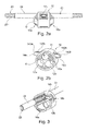
Figure 4a est une vue en perspective d'un tiroir de connexion. - La
Figure 4b montre le tiroir de connexion de laFigure 4a en position dans un tunnel de guidage. - La
Figure 5 est une vue en perspective d'une pluralité de bagues métalliques constituant les électrodes d'une sonde multipolaire. - La
Figure 6 représente des grappes de bagues métalliques disposées de manière à réaliser des sondes multipolaires conformes à l'invention. - La
Figure 7a est une vue en perspective en coupe d'une bague métallique portant des rainures longitudinales. - La
Figure 7b est une vue en perspective de la bague de laFigure 7a . - La
Figure 8a est une vue en perspective d'un élément de sonde multipolaire entourée d'une gaine collective thermorétractable. - La
Figure 8b montre l'élément de sonde de laFigure 8a après chauffage de la gaine thermorétractable. - La
Figure 8c montre l'élément de sonde de laFigure 8b munie de surfaces de détection/stimulation. - La
figure 9a est une vue en perspective éclatée d'une bague munie d'un joint de colle. - La
figure 9b est une vue de détail de laFigure 9a . - La
Figure 10a est une vue en perspective éclatée d'une bague munie d'un lamage d'extrémité. - La
Figure 10b montre la bague de laFigure 10a équipée de microcâbles. - Les
Figures 11a à 12b sont des vues en coupe de variantes de réalisation de la bague métallique. - Les
Figures 13a à illustrent encore deux autres variantes respectives de réalisation de la bague métallique.13c et 14a à 14b
- The
Figure 1a is a perspective view in section of a metal ring constituting an electrode of a multipolar probe according to the invention. - The
Figure 1b shows the ring of theFigure 1a equipped with three microcables. - The
Figure 1c shows the ring of theFigure 1b in the perforation position of a microcable. - The
Figure 2a is a side view of a metal ring with two end chamfers. - The
Figure 2b is a perspective view of the ring of theFigure 2a . - The
Figure 3 is an exploded view of the ring ofFigures 2a and 2b . - The
Figure 4a is a perspective view of a connection drawer. - The
Figure 4b shows the connection drawer of theFigure 4a in position in a guide tunnel. - The
Figure 5 is a perspective view of a plurality of metal rings constituting the electrodes of a multipolar probe. - The
Figure 6 represents clusters of metal rings arranged so as to produce multipole probes according to the invention. - The
Figure 7a is a perspective view in section of a metal ring bearing longitudinal grooves. - The
Figure 7b is a perspective view of the ring of theFigure 7a . - The
Figure 8a is a perspective view of a multipole probe element surrounded by a heat shrinkable sheath. - The
Figure 8b shows the probe element of theFigure 8a after heating the heat-shrinkable sheath. - The
Figure 8c shows the probe element of theFigure 8b equipped with detection / stimulation surfaces. - The
figure 9a is an exploded perspective view of a ring provided with an adhesive seal. - The
figure 9b is a detail view of theFigure 9a . - The
Figure 10a is an exploded perspective view of a ring provided with an end counterbore. - The
Figure 10b shows the ring of theFigure 10a equipped with microcables. - The
Figures 11a to 12b are sectional views of alternative embodiments of the metal ring. - The
Figures 13a to 13c and 14a to 14b illustrate two other respective embodiments of the metal ring.
On va maintenant décrire un exemple de réalisation des électrodes de la sonde multipolaire selon l'invention.An embodiment of the electrodes of the multipolar probe according to the invention will now be described.
Sur les
La bague 10 est en un matériau insensible au phénomène d'électrocorrosion tel qu'un alliage de platine iridié (typiquement 90/10) ou d'un autre métal noble, comme le palladium ou le tantale.The
Pour obtenir une sonde fiable, il est proposé d'adopter la technique du câblage individualisé, chaque électrode ou groupe d'électrodes étant reliée(s) au même pôle du générateur implanté, c'est-à-dire chaque bague ou groupe de bagues étant connectée(s) à un microcâble lui-même relié au pôle considéré, l'ensemble de la structure formant une sonde de type monocorps.To obtain a reliable probe, it is proposed to adopt the individualized wiring technique, each electrode or group of electrodes being connected to the same pole of the implanted generator, that is to say each ring or group of rings. being connected (s) to a microcable itself connected to the pole, the whole structure forming a single-body type probe.
La difficulté technique est alors d'établir une connexion fiabilisée industrialisable avec celui des microcâbles qui constitue la ligne de conduction, tout en préservant l'isolement des autres microcâbles non connectés, le tout devant être contenu dans un diamètre de 1 à 2 French (0,33 à 0,66 mm) pour préserver les bénéfices de tels dispositifs, par exemple le passage d'anastomoses pour établir un système stimulant du ventricule gauche via deux zones distinctes.The technical difficulty is then to establish an industrialized reliable connection with that of the microcables that constitutes the conduction line, while preserving the isolation of the other unconnected microcables, all to be contained in a diameter of 1 to 2 French (0 , 33 to 0.66 mm) to preserve the benefits of such devices, for example the passage of anastomoses to establish a left ventricular stimulating system via two distinct areas.
La solution proposée, telle qu'illustrée sur les
Plus précisément, une de ces lumières, la lumière 11 dite "de connexion électrique", reçoit le microcâble 21 prévu pour être connecté à la bague 10 et à un pôle du générateur.More precisely, one of these lights, the so-called "electrical connection" light 11, receives the microcable 21 intended to be connected to the
Le microcâble est normalement un microcâble non dénudé, pour bénéficier aux mieux de tous les avantages des l'invention, mais en variante il peut être dénudé localement, les moyens que l'on va décrire étant alors destinés à réaliser la prise de contact directement sur la région dénudée du câble, sans perforation de l'isolant.The microcable is normally a non-bare microcable, to benefit the best of all the advantages of the invention, but alternatively it can be stripped locally, the means that will be described are then intended to make the contact directly on the stripped region of the cable without perforation of the insulation.
Les deux autres lumières longitudinales 12a et 12b sont dites "de traversée d'électrode" dans la mesure où elles permettent aux microcâbles 22a et 22b, qui ne doivent pas être connectés à la bague 10, de seulement la traverser.The other two
La lumière de connexion 11 présente une ouverture circulaire de diamètre sensiblement égal à celui du microcâble connecté 21 (moyennant un jeu minimum de montage, lié aux tolérances dimensionnelles des composants). À l'inverse, les lumières de traversée d'électrode 12a et 12b peuvent avoir un diamètre supérieur à celui des microcâbles non connectés 22a et 22b, ceci afin d'éviter tout risque d'endommagement de l'isolant des microcâbles à proximité immédiate de la bague ; cette augmentation de diamètre permet également d'insérer dans les lumières de traversée d'électrode une gaine isolante supplémentaire de protection (non représentée), permettant en outre, du point de vue mécanique, de contribuer à la gestion des gradients de raideur à proximité immédiate de la bague. On peut toutefois également prévoir, dans une zone centrale longitudinale de la bague 10, un rétrécissement des lumières de traversée d'électrode 12a, 12b à un diamètre sensiblement égal à celui de la lumière de connexion 11, de manière à garantir le centrage des microcâbles non connectés 22a et 22b. La zone 15 de plus fort diamètre est montrée plus particulièrement sur la vue de détail de la
Il est également possible de remplacer les lumières de traversée d'électrode individuelles 12a et 12b par une seule lumière (non représentée) apte à recevoir une pluralité de microcâbles non connectés. Cette lumière unique peut par exemple avoir une forme oblongue courbée. Dans le mode de réalisation présenté, trois lignes de conduction indépendantes, portées par les microcâbles 21, 22a et 22b, ont été prises en compte afin d'optimiser le rapport diamètre hors tout/nombre de lignes. Néanmoins, une approche similaire est envisageable pour deux à quatre lignes indépendantes ou redondantes, deux lignes étant alors affectées à un groupe d'électrodes.It is also possible to replace the individual
Pour la version illustrée à trois lignes, il est possible d'attribuer différentes fonctions spécifiques au troisième microcâble lorsque le générateur ne dispose que d'un port de connexion bipolaire (connexion de typelS1) :
- redondance de la connexion avec une série d'électrodes ;
- radio-opacité au moyen d'une section de brins en matériau radio-opaque, par exemple majoritairement en Ptlr ;
- résistance mécanique pure en traction et en flexion, grâce à une section par exemple majoritairement en MP35 NLT.
- redundancy of the connection with a series of electrodes;
- radiopacity by means of a section of strands of radio-opaque material, for example predominantly Ptlr;
- pure mechanical strength in traction and flexion, thanks to a section for example mainly in MP35 NLT.
Les microcâbles 21, 22a et 22b sont formés d'un conducteur central plein 23 entouré d'une gaine 24 en matériau polymère isolant.The
Le conducteur central 23 est avantageusement une structure multifilaire se présentant sous forme d'un toron d'une pluralité de brins conducteurs 231 de faible diamètre. Typiquement, un toron comporte sept brins 231 de 33 µm de diamètre pour un diamètre total de 100 µm. Selon un exemple de réalisation particulier, un brin 231 présente une structure bi-matériau, à savoir une âme en platine et une enveloppe inoxydable en un alliage du type MP35 N (35% Ni, 35% Co, 20% Cr et 10% Mo) ou MP35 NLT, dont l'avantage essentiel est son extrême endurance en fatigue. La réduction en diamètre des brins unitaires permet de réduire la contrainte appliquée à chacun d'entre eux, et donc d'augmenter les performances en fatigue de la structure du toron. Une telle structure, sans lumière interne et avec plusieurs brins torsadés ensemble, est capable d'assurer à la fois l'endurance à l'encontre des mouvements cardiaques et la résistance aux sollicitations liées à la pose.The
Si besoin, à titre de précaution supplémentaire, le MP35N peut être revêtu de platine afin de garantir une protection complète de la jonction électrique à l'encontre de l'électrocorrosion, au cas où l'étanchéité au niveau de la ponction à travers l'isolant, ou entre le tiroir de connexion et le tunnel de guidage, ou même l'étanchéité du collage éventuel, ne seraient pas suffisantes.If necessary, as an additional precaution, the MP35N can be coated with platinum in order to guarantee complete protection of the electrical junction against electrocorrosion, in case the sealing at the puncture through the insulation, or between the connection slide and the guide tunnel, or even the sealing of the possible bonding, would not be sufficient.
En ce qui concerne la gaine isolante 24, celle-ci doit répondre aux caractéristiques suivantes : résistance à la fatigue, isolement électrique, bio-compatibilité à long terme, biostabilité, possibilité de transformation et compatibilité avec le conducteur central 23.As regards the insulating
Les matériaux pouvant être utilisés dans ce cadre sont notamment les matériaux du groupe comprenant : les polyuréthannes (PU), les polyesters (PET), les polyamides (PA), les polycarbonates (PC), les polyimides, les polymères fluorés, le polyéther-éther-kétone (PEEK), le poly-p-xylylène (parylène) et le polyméthacrylate de méthyle (PMM).The materials that can be used in this context include the materials of the group comprising: polyurethanes (PU), polyesters (PET), polyamides (PA), polycarbonates (PC), polyimides, fluoropolymers, polyether ether-ketone (PEEK), poly-p-xylylene (parylene) and polymethylmethacrylate (PMM).
Cependant, on privilégiera les matériaux à forte inertie chimique comme les polymères fluorés, qui présentent également une très bonne qualité d'isolement. Parmi ces composés, on peut notamment citer les matériaux du groupe comprenant : le PTFE (polytétrafluoroéthylène), le FEP (propylène perfluoré), le PFA (résine de copolymère perfluoroalkoxy), le THV (tétrafluoroéthylène, hexafluoropropylène, fluorure de vinylidène), le PVDF (polyfluorure de vinylidène), l'EFEP (éthylène propylène éthylène fluoré) et l'ETFE (éthylène tétrafluoroéthylène).However, preference will be given to materials with high chemical inertness, such as fluoropolymers, which also have a very good quality of insulation. Among these compounds, there may be mentioned materials of the group comprising: PTFE (polytetrafluoroethylene), FEP (perfluorinated propylene), PFA (perfluoroalkoxy copolymer resin), THV (tetrafluoroethylene, hexafluoropropylene, vinylidene fluoride), PVDF (polyvinylidene fluoride), EFEP (ethylene propylene fluorinated ethylene) and ETFE (ethylene tetrafluoroethylene).
Les procédés de réalisation de la gaine 24 d'isolement sur le conducteur central 23 sont fonction des matériaux utilisés, par exemple : co-extrusion sur le conducteur (pour PU, PA, PEEK, polyimides et polymères fluorés) ; dépôt par trempage dans une solution (pour PU, PA et polyimides) ; échauffement d'un tube thermorétractable (pour PET et polymères fluorés) ; dépôt chimique par voie gazeuse (pour le parylène) ; traitements plasma pour améliorer l'adhésion entre les couches.The methods for producing the insulating
On notera par ailleurs que, bien que l'invention ait été illustrée avec une unique couche d'un même matériau gainant les microcâbles 21, 22a et 22b, il est possible de prévoir plusieurs couches successives formant la gaine 24, par exemple une couche de PET et une couche de ETFE. Dans l'application proposée ici, la gaine isolante 24 a une épaisseur typique de 5 à 20 µm.Note also that, although the invention has been illustrated with a single layer of the same material sheathing the
Comme le montrent les
Plus précisément, les tiroirs de connexion comportent une extrémité interne 141a, 141b de forme saillante et peuvent coulisser respectivement dans des tunnels de guidage 13a, 13b transversaux à la bague 10, aménagés entre la périphérie de la bague et la lumière de connexion 11.More specifically, the connection drawers comprise an
Pour éviter qu'ils ne forment des protubérances à l'extérieur de la périphérie de la bague 10, les tiroirs de connexion 14a, 14b en position de perforation sont de préférence escamotés à l'intérieur des tunnels de guidage 13a, 13b respectifs.To prevent them from forming protuberances outside the periphery of the
L'ajustement entre un tiroir de connexion et le tunnel de guidage associé est prévu suffisamment serré afin :
- d'établir la liaison électrique entre le tiroir et la bague 10 ;
- de maintenir le tiroir en position fermée. Sur ce point, il est possible d'aménager des bossages 142a, 142b sur les tiroirs 14a, 14b afin de localiser et mieux maitriser l'interférence mécanique ; et
- d'empêcher l'infiltration de fluides corporels vers les brins du microcâble 21, afin de prévenir les risques de corrosion.
- to establish the electrical connection between the drawer and the
ring 10; - keep the drawer in the closed position. On this point, it is possible to arrange
bosses drawers - to prevent the infiltration of body fluids towards the strands of the
microcable 21, to prevent the risk of corrosion.
En pratique, la perforation effective de la gaine isolante 24 du microcâble 21 à connecter est réalisée par enfoncement à force au moyen de mors de sertissage venant en appui sur des surfaces 143a et 143b de poussée des tiroirs de connexion 14a, 14b.In practice, the effective perforation of the insulating
Le système à deux tiroirs de connexion opposés permet de fiabiliser la connexion microcâble/bague, d'une part, par un "effet tenaille" sur le microcâble recevant des pressions de connexion opposées et, d'autre part, par redondance du contact sur le microcâble.The system with two opposed connection drawers makes it possible to make the microcable / ring connection reliable, on the one hand, by a pincer effect on the microcable receiving opposite connection pressures and, on the other hand, by redundancy of the contact on the microcable.
Idéalement, les tiroirs de connexion opposés 14a, 14b coulissent dans les tunnels 13a, 13b selon un même axe A-A de coulissement passant par le centre de la lumière de connexion 11, afin d'orienter les surfaces de poussée 143a, 143b perpendiculairement au mouvement des mors de sertissage. Une solution alternative consiste à rendre parallèles les surfaces de poussée des tiroirs de connexion, permettant d'utiliser un équipement de sertissage à mors parallèles et non concentriques.Ideally, the
La
La solution alternative de la
Lors de l'insertion des microcâbles, les extrémités internes saillantes 141a, 141b de perforation des tiroirs de connexion 14a, 14b sont complètement escamotées à l'intérieur des tunnels de guidage 13a, 13b, évitant ainsi toute difficulté d'introduction des microcâbles puisque les lumières de connexion 11 sont alors totalement dégagées.When the microcables are inserted, the projecting
Un ou plusieurs zones d'attache temporaire, telle que la zone 144 de la
On peut remarquer que l'opération de sertissage concentrique, maitrisé en déplacement, ne nécessite pas de repérage angulaire de l'ensemble. De plus, une inspection visuelle rapide de production et/ou de contrôle final permet d'identifier l'état du système, à savoir état "connecté" pour des électrodes sans protubérance, ou état "non connecté" pour des électrodes avec une ou deux protubérances.It may be noted that the concentric crimping operation, mastered in displacement, does not require angular identification of the assembly. In addition, a rapid visual inspection of production and / or final control makes it possible to identify the state of the system, namely "connected" state for electrodes without protuberance, or "unconnected" state for electrodes with one or two protuberances.
Un procédé de réalisation préférentiel de réalisation des bagues 10 est le procédé MICA Freeform (marque déposée de la société Microfabrica, Inc.) pour ses spécificités : extrême précision, intégration des composants, etc. Grâce à cette technologie par strates successives, la bague métallique 10, les tiroirs de connexion 14a, 14b et les zones 144 d'attache temporaire ne forment qu'une seule pièce monobloc.A preferred method for producing
Dans le but d'améliorer par effet de pointe la transmission des impulsions électriques aux tissus visés, il est prévu sur la périphérie de la bague 10 des zones, référencées 18a, 18b et 18c sur les
Cette gaine collective 30 évite toute discontinuité de l'isolement global et la création de gradients de raideur locaux. Des fenêtres 31 sont découpées dans la gaine collective 30 par ablation laser autour de surfaces de stimulation, à savoir ici les zones 18a, 18b et 18c de rainurage longitudinal. Seules ces zones de rainurage en contact avec les tissus sont stimulantes.This
Sur les
Les chanfreins 16a, 16b sont réalisés en même temps que la bague 10 selon la technologie MICA Freeform, ce qui leur confère le profil en escalier que l'on peut observer sur les figures précitées.The
Afin de permettre aux microcâbles de venir en appui contre une surface rigide le long d'une de leur génératrice extérieure, il est possible, comme le montrent les
Le gradient de rigidité et l'étanchéité de la structure peuvent encore être améliorés par l'ajout d'un joint de colle souple 40 aux extrémités de la bague 10, sous la gaine collective, comme représenté sur les
Les
- la variante de la
Figure 11a met enoeuvre un poinçon 14 de connexion découpé dans la bague 10, apte à perforer la gaine d'un microcâble disposé dans la lumière de connexion 11 par déformation maitrisée de la structure circulaire de la bague sans rupture des points d'attache du poinçon 14 avec la bague. L'avantage de cette variante est la continuité de matière dans la liaison électrique poinçon/bague et le maintien d'une étanchéité optimale ; - sur la
figure 11b , la bague 10 et l'organe 14' de perforation sont constitués de deux matériaux de rigidités différentes, combinés dans la même section de matriçage afin de programmer la déformation localisée de la lumière de connexion 11. Cette variante ne nécessite pas de repérage angulaire pendant le sertissage ; - les variantes des
Figures 11c à 12b présentent des éléments 14", 14"' de connexion mobiles uniques de type fourche, dont les avantages sont une double découpe de la gaine isolante du microcâble à connecter et un effet de "tenaille" natif. Plus particulièrement, le mode de réalisation desFigures comporte un système de clipsage de l'élément 14"' de connexion dans la lumière de connexion 11 ;12a et 12b - la variante des
Figures 13a à 13c illustre une alternative au mouvement de translation des tiroirs 14a, 14b selon un axe A-A passant par le centre de la lumière de connexion 11 ; - la variante des
Figures 14a à 14b illustre une alternative mettant en oeuvre une rotation des tiroirs de connexion 14a, 14 dans leur tunnel de guidage 13a, 13b.
- the variant of the
Figure 11a uses aconnection punch 14 cut into thering 10, able to perforate the sheath of a microcable arranged in theconnection lumen 11 by controlled deformation of the circular structure of the ring without breaking the points of attachment of thepunch 14 with the ring. The advantage of this variant is the continuity of material in the electrical punch / ring connection and the maintenance of an optimal seal; - on the
figure 11b , thering 10 and the perforation member 14 'consist of two materials of different stiffnesses, combined in the same stamping section in order to program the localized deformation of theconnection lumen 11. This variant does not require any angular registration during crimping; - variants of
Figures 11c to 12b feature unique 14 ", 14"'mobile connection elements of the fork type, the advantages of which are a double cut of the insulating jacket of the microcable to be connected and a native "pincer" effect. More particularly, the embodiment of theFigures 12a and 12b comprises a clipping system of theelement 14 "'of connection in theconnection lumen 11; - the variant of
Figures 13a to 13c illustrates an alternative to the translation movement of thedrawers connection lumen 11; - the variant of
Figures 14a to 14b illustrates an alternative implementing a rotation of theconnection drawers guide tunnel
Claims (24)
Applications Claiming Priority (1)
| Application Number | Priority Date | Filing Date | Title |
|---|---|---|---|
| FR1255544A FR2991882A1 (en) | 2012-06-13 | 2012-06-13 | ELECTRODE STRUCTURE FOR A MULTIPOLAR DETECTION / STIMULATION MICROSONDE INTENDED TO BE IMPLANTED INTO A CARDIAC OR CEREBRAL VESSEL |
Publications (2)
| Publication Number | Publication Date |
|---|---|
| EP2674190A1 true EP2674190A1 (en) | 2013-12-18 |
| EP2674190B1 EP2674190B1 (en) | 2014-12-17 |
Family
ID=47221981
Family Applications (1)
| Application Number | Title | Priority Date | Filing Date |
|---|---|---|---|
| EP20120194864 Active EP2674190B1 (en) | 2012-06-13 | 2012-11-29 | Electrode structure for a multipolar stimulation/sensing microprobe for implantation in a heart or brain blood vessel |
Country Status (3)
| Country | Link |
|---|---|
| US (1) | US9067058B2 (en) |
| EP (1) | EP2674190B1 (en) |
| FR (1) | FR2991882A1 (en) |
Cited By (1)
| Publication number | Priority date | Publication date | Assignee | Title |
|---|---|---|---|---|
| EP3591763A1 (en) | 2018-07-06 | 2020-01-08 | Sorin CRM SAS | Connection method for connecting an insulated micro-conductor |
Families Citing this family (12)
| Publication number | Priority date | Publication date | Assignee | Title |
|---|---|---|---|---|
| EP2664354B1 (en) | 2012-05-16 | 2015-09-16 | Sorin CRM SAS | Medical lead with a ring electrode for implantation in a cardiac or cerebral blood vessel and a method for its manufacture |
| US11179566B2 (en) * | 2014-06-03 | 2021-11-23 | Cochlear Limited | Fitting method using channels |
| EP3185248B1 (en) | 2015-12-23 | 2019-11-06 | Heraeus Deutschland GmbH & Co. KG | Process for electrically contacting a coated lead with a particle |
| EP3185363B1 (en) | 2015-12-23 | 2020-02-12 | Heraeus Deutschland GmbH & Co. KG | Process for electrically contacting a coated lead with a layer |
| EP3542853B1 (en) | 2018-03-23 | 2021-05-05 | Heraeus Deutschland GmbH & Co. KG | Manufacturing method for a microlead |
| EP3542854B1 (en) | 2018-03-23 | 2021-06-30 | Heraeus Deutschland GmbH & Co. KG | Manufacturing method for a multi electrode system |
| DE102018221355B4 (en) | 2018-12-10 | 2022-08-18 | Heraeus Deutschland GmbH & Co. KG | Contacting method and system |
| DE102018221635B8 (en) | 2018-12-13 | 2020-08-06 | Heraeus Deutschland GmbH & Co. KG | Contacting procedure and system |
| DE102019218477B4 (en) * | 2019-11-28 | 2022-01-05 | Heraeus Deutschland GmbH & Co. KG | Micro-lead for directional stimulation |
| DE102020118371A1 (en) | 2020-07-13 | 2022-01-13 | Heraeus Deutschland GmbH & Co. KG | Multi-layer ring electrode with multiple openings |
| DE102020118373B4 (en) | 2020-07-13 | 2023-11-02 | Heraeus Deutschland GmbH & Co. KG | Multi-layer ring electrode with multiple openings and low-melting internal structures |
| DE102020123651B4 (en) | 2020-09-10 | 2023-11-09 | Heraeus Deutschland GmbH & Co. KG | Multi-layer ring electrode with clamp |
Citations (10)
| Publication number | Priority date | Publication date | Assignee | Title |
|---|---|---|---|---|
| FR1254548A (en) | 1960-01-13 | 1961-02-24 | Device for transmitting the motive energy of a motor vehicle to various mechanical receivers | |
| US4387727A (en) * | 1981-03-30 | 1983-06-14 | Medtronic, Inc. | Coaxial service kit |
| US4590950A (en) * | 1982-12-20 | 1986-05-27 | Telectronics Pty, Limited | Electrical connection |
| US5370684A (en) | 1986-12-12 | 1994-12-06 | Sorin Biomedica S.P.A. | Prosthesis of polymeric material coated with biocompatible carbon |
| US5387247A (en) | 1983-10-25 | 1995-02-07 | Sorin Biomedia S.P.A. | Prosthetic device having a biocompatible carbon film thereon and a method of and apparatus for forming such device |
| US7364479B1 (en) | 2007-02-02 | 2008-04-29 | Pacesetter, Inc. | Crimp connector for connecting a conductor cable and electrode of an implantable cardiac electrotherapy lead |
| US20080114230A1 (en) | 2006-11-14 | 2008-05-15 | Bruce Addis | Electrode support |
| EP1983881A2 (en) | 2006-02-03 | 2008-10-29 | Cannuflow, Inc. | Anti-extravasation sheath |
| US20100331934A1 (en) * | 2009-06-29 | 2010-12-30 | Boston Scientific Neuromodulation Corporation | Multi-element contact assemblies for electrical stimulation systems and systems and methods of making and using |
| EP2455131A1 (en) | 2010-11-19 | 2012-05-23 | Sorin CRM SAS | Probe for stimulating a left cavity of the heart which can be implanted in the coronary network |
Family Cites Families (2)
| Publication number | Priority date | Publication date | Assignee | Title |
|---|---|---|---|---|
| US6660935B2 (en) * | 2001-05-25 | 2003-12-09 | Gelcore Llc | LED extrusion light engine and connector therefor |
| FR2910818A1 (en) | 2006-12-28 | 2008-07-04 | Ela Medical Soc Par Actions Si | MULTIPLEXED ELECTRODE CONTROLLED SWITCHING CIRCUIT FOR ACTIVE ACTIVE IMPLANTABLE DISPOSITION |
-
2012
- 2012-06-13 FR FR1255544A patent/FR2991882A1/en active Pending
- 2012-11-29 EP EP20120194864 patent/EP2674190B1/en active Active
-
2013
- 2013-06-12 US US13/916,444 patent/US9067058B2/en active Active
Patent Citations (10)
| Publication number | Priority date | Publication date | Assignee | Title |
|---|---|---|---|---|
| FR1254548A (en) | 1960-01-13 | 1961-02-24 | Device for transmitting the motive energy of a motor vehicle to various mechanical receivers | |
| US4387727A (en) * | 1981-03-30 | 1983-06-14 | Medtronic, Inc. | Coaxial service kit |
| US4590950A (en) * | 1982-12-20 | 1986-05-27 | Telectronics Pty, Limited | Electrical connection |
| US5387247A (en) | 1983-10-25 | 1995-02-07 | Sorin Biomedia S.P.A. | Prosthetic device having a biocompatible carbon film thereon and a method of and apparatus for forming such device |
| US5370684A (en) | 1986-12-12 | 1994-12-06 | Sorin Biomedica S.P.A. | Prosthesis of polymeric material coated with biocompatible carbon |
| EP1983881A2 (en) | 2006-02-03 | 2008-10-29 | Cannuflow, Inc. | Anti-extravasation sheath |
| US20080114230A1 (en) | 2006-11-14 | 2008-05-15 | Bruce Addis | Electrode support |
| US7364479B1 (en) | 2007-02-02 | 2008-04-29 | Pacesetter, Inc. | Crimp connector for connecting a conductor cable and electrode of an implantable cardiac electrotherapy lead |
| US20100331934A1 (en) * | 2009-06-29 | 2010-12-30 | Boston Scientific Neuromodulation Corporation | Multi-element contact assemblies for electrical stimulation systems and systems and methods of making and using |
| EP2455131A1 (en) | 2010-11-19 | 2012-05-23 | Sorin CRM SAS | Probe for stimulating a left cavity of the heart which can be implanted in the coronary network |
Cited By (1)
| Publication number | Priority date | Publication date | Assignee | Title |
|---|---|---|---|---|
| EP3591763A1 (en) | 2018-07-06 | 2020-01-08 | Sorin CRM SAS | Connection method for connecting an insulated micro-conductor |
Also Published As
| Publication number | Publication date |
|---|---|
| EP2674190B1 (en) | 2014-12-17 |
| US20130338745A1 (en) | 2013-12-19 |
| US9067058B2 (en) | 2015-06-30 |
| FR2991882A1 (en) | 2013-12-20 |
Similar Documents
| Publication | Publication Date | Title |
|---|---|---|
| EP2674190B1 (en) | Electrode structure for a multipolar stimulation/sensing microprobe for implantation in a heart or brain blood vessel | |
| EP2664354B1 (en) | Medical lead with a ring electrode for implantation in a cardiac or cerebral blood vessel and a method for its manufacture | |
| EP2878332B1 (en) | Detection/stimulation microprobe implantable in a vessel of the venous, lymphatic or arterial network | |
| EP2455131B1 (en) | Probe for stimulating a left cavity of the heart which can be implanted in the coronary network | |
| EP3173126B1 (en) | Implantable capsule, in particular an autonomous cardiac stimulation capsule, and its method of assembly | |
| EP4043065A1 (en) | Detection/stimulation microprobe implantable in venous, arterial or lymphatic systems | |
| EP3058983B1 (en) | Detection/stimulation microprobe, in particular for multipoint neuromodulation of the central nervous system | |
| EP2500998B1 (en) | Electrical connection plug for multipole probe of an active implantable medical device | |
| EP2647406B1 (en) | Electrical connection plug for multipolar probe of an active implantable medical device | |
| EP2719422A1 (en) | Implantable multipolar detection/stimulation microprobe | |
| EP3075411B1 (en) | Multi-electrode probe with multiplexed control, in particular for cardiac stimulation, and associated connection method | |
| EP2544312B1 (en) | Connector for multipolar probe | |
| EP3476284B1 (en) | Biocompatible integrated monolithic sensor, notably for an active implantable medical device | |
| US20200009370A1 (en) | Connection method for connecting an isolated micro-conductor | |
| EP2559453B1 (en) | Lead implantable in the coronary vessels for multi-zone stimulation of a left heart chamber | |
| EP2465425B1 (en) | Lead for an active implantable medical device, comprising a microchip, in particular for multiplexing | |
| EP2719423B1 (en) | Atraumatic detection/stimulation microprobe | |
| EP1557194B1 (en) | Single-piece defibrillation sonde | |
| EP2275170B1 (en) | Assembly suitable for implantation in the coronary sinus, including a stimulation probe with anchoring screw | |
| EP1036572A1 (en) | Cardiac lead implantable in the coronary veins for stimulating the left atria | |
| EP0208154B1 (en) | Implantable electrode | |
| FR3071973A1 (en) | HERMETIC AND INSULATING CROSSWAY FOR A HOUSING, IN PARTICULAR TITANIUM, OF AN ELECTRONIC DEVICE, AND METHODS OF MAKING SAME |
Legal Events
| Date | Code | Title | Description |
|---|---|---|---|
| PUAI | Public reference made under article 153(3) epc to a published international application that has entered the european phase |
Free format text: ORIGINAL CODE: 0009012 |
|
| 17P | Request for examination filed |
Effective date: 20121129 |
|
| AK | Designated contracting states |
Kind code of ref document: A1 Designated state(s): AL AT BE BG CH CY CZ DE DK EE ES FI FR GB GR HR HU IE IS IT LI LT LU LV MC MK MT NL NO PL PT RO RS SE SI SK SM TR |
|
| AX | Request for extension of the european patent |
Extension state: BA ME |
|
| RIC1 | Information provided on ipc code assigned before grant |
Ipc: A61N 1/05 20060101AFI20140521BHEP Ipc: H01R 4/24 20060101ALI20140521BHEP |
|
| GRAP | Despatch of communication of intention to grant a patent |
Free format text: ORIGINAL CODE: EPIDOSNIGR1 |
|
| INTG | Intention to grant announced |
Effective date: 20140704 |
|
| RBV | Designated contracting states (corrected) |
Designated state(s): AL AT BE BG CH CY CZ DE DK EE ES FI FR GB GR HR HU IE IS IT LI LT LU LV MC MK MT NL NO PL PT RO RS SE SI SK SM TR |
|
| GRAS | Grant fee paid |
Free format text: ORIGINAL CODE: EPIDOSNIGR3 |
|
| GRAA | (expected) grant |
Free format text: ORIGINAL CODE: 0009210 |
|
| AK | Designated contracting states |
Kind code of ref document: B1 Designated state(s): AL AT BE BG CH CY CZ DE DK EE ES FI FR GB GR HR HU IE IS IT LI LT LU LV MC MK MT NL NO PL PT RO RS SE SI SK SM TR |
|
| REG | Reference to a national code |
Ref country code: GB Ref legal event code: FG4D Free format text: NOT ENGLISH |
|
| REG | Reference to a national code |
Ref country code: CH Ref legal event code: EP |
|
| REG | Reference to a national code |
Ref country code: IE Ref legal event code: FG4D Free format text: LANGUAGE OF EP DOCUMENT: FRENCH |
|
| REG | Reference to a national code |
Ref country code: AT Ref legal event code: REF Ref document number: 701444 Country of ref document: AT Kind code of ref document: T Effective date: 20150115 |
|
| REG | Reference to a national code |
Ref country code: DE Ref legal event code: R096 Ref document number: 602012004347 Country of ref document: DE Effective date: 20150129 |
|
| PG25 | Lapsed in a contracting state [announced via postgrant information from national office to epo] |
Ref country code: LT Free format text: LAPSE BECAUSE OF FAILURE TO SUBMIT A TRANSLATION OF THE DESCRIPTION OR TO PAY THE FEE WITHIN THE PRESCRIBED TIME-LIMIT Effective date: 20141217 Ref country code: NO Free format text: LAPSE BECAUSE OF FAILURE TO SUBMIT A TRANSLATION OF THE DESCRIPTION OR TO PAY THE FEE WITHIN THE PRESCRIBED TIME-LIMIT Effective date: 20150317 Ref country code: FI Free format text: LAPSE BECAUSE OF FAILURE TO SUBMIT A TRANSLATION OF THE DESCRIPTION OR TO PAY THE FEE WITHIN THE PRESCRIBED TIME-LIMIT Effective date: 20141217 |
|
| REG | Reference to a national code |
Ref country code: LT Ref legal event code: MG4D |
|
| PG25 | Lapsed in a contracting state [announced via postgrant information from national office to epo] |
Ref country code: HR Free format text: LAPSE BECAUSE OF FAILURE TO SUBMIT A TRANSLATION OF THE DESCRIPTION OR TO PAY THE FEE WITHIN THE PRESCRIBED TIME-LIMIT Effective date: 20141217 Ref country code: SE Free format text: LAPSE BECAUSE OF FAILURE TO SUBMIT A TRANSLATION OF THE DESCRIPTION OR TO PAY THE FEE WITHIN THE PRESCRIBED TIME-LIMIT Effective date: 20141217 Ref country code: GR Free format text: LAPSE BECAUSE OF FAILURE TO SUBMIT A TRANSLATION OF THE DESCRIPTION OR TO PAY THE FEE WITHIN THE PRESCRIBED TIME-LIMIT Effective date: 20150318 Ref country code: LV Free format text: LAPSE BECAUSE OF FAILURE TO SUBMIT A TRANSLATION OF THE DESCRIPTION OR TO PAY THE FEE WITHIN THE PRESCRIBED TIME-LIMIT Effective date: 20141217 Ref country code: RS Free format text: LAPSE BECAUSE OF FAILURE TO SUBMIT A TRANSLATION OF THE DESCRIPTION OR TO PAY THE FEE WITHIN THE PRESCRIBED TIME-LIMIT Effective date: 20141217 |
|
| REG | Reference to a national code |
Ref country code: AT Ref legal event code: MK05 Ref document number: 701444 Country of ref document: AT Kind code of ref document: T Effective date: 20141217 |
|
| PG25 | Lapsed in a contracting state [announced via postgrant information from national office to epo] |
Ref country code: NL Free format text: LAPSE BECAUSE OF FAILURE TO SUBMIT A TRANSLATION OF THE DESCRIPTION OR TO PAY THE FEE WITHIN THE PRESCRIBED TIME-LIMIT Effective date: 20141217 |
|
| PG25 | Lapsed in a contracting state [announced via postgrant information from national office to epo] |
Ref country code: CZ Free format text: LAPSE BECAUSE OF FAILURE TO SUBMIT A TRANSLATION OF THE DESCRIPTION OR TO PAY THE FEE WITHIN THE PRESCRIBED TIME-LIMIT Effective date: 20141217 Ref country code: ES Free format text: LAPSE BECAUSE OF FAILURE TO SUBMIT A TRANSLATION OF THE DESCRIPTION OR TO PAY THE FEE WITHIN THE PRESCRIBED TIME-LIMIT Effective date: 20141217 Ref country code: EE Free format text: LAPSE BECAUSE OF FAILURE TO SUBMIT A TRANSLATION OF THE DESCRIPTION OR TO PAY THE FEE WITHIN THE PRESCRIBED TIME-LIMIT Effective date: 20141217 Ref country code: SK Free format text: LAPSE BECAUSE OF FAILURE TO SUBMIT A TRANSLATION OF THE DESCRIPTION OR TO PAY THE FEE WITHIN THE PRESCRIBED TIME-LIMIT Effective date: 20141217 Ref country code: RO Free format text: LAPSE BECAUSE OF FAILURE TO SUBMIT A TRANSLATION OF THE DESCRIPTION OR TO PAY THE FEE WITHIN THE PRESCRIBED TIME-LIMIT Effective date: 20141217 |
|
| PG25 | Lapsed in a contracting state [announced via postgrant information from national office to epo] |
Ref country code: AT Free format text: LAPSE BECAUSE OF FAILURE TO SUBMIT A TRANSLATION OF THE DESCRIPTION OR TO PAY THE FEE WITHIN THE PRESCRIBED TIME-LIMIT Effective date: 20141217 Ref country code: PL Free format text: LAPSE BECAUSE OF FAILURE TO SUBMIT A TRANSLATION OF THE DESCRIPTION OR TO PAY THE FEE WITHIN THE PRESCRIBED TIME-LIMIT Effective date: 20141217 Ref country code: IS Free format text: LAPSE BECAUSE OF FAILURE TO SUBMIT A TRANSLATION OF THE DESCRIPTION OR TO PAY THE FEE WITHIN THE PRESCRIBED TIME-LIMIT Effective date: 20150417 |
|
| REG | Reference to a national code |
Ref country code: DE Ref legal event code: R097 Ref document number: 602012004347 Country of ref document: DE |
|
| REG | Reference to a national code |
Ref country code: FR Ref legal event code: PLFP Year of fee payment: 4 |
|
| PLBE | No opposition filed within time limit |
Free format text: ORIGINAL CODE: 0009261 |
|
| STAA | Information on the status of an ep patent application or granted ep patent |
Free format text: STATUS: NO OPPOSITION FILED WITHIN TIME LIMIT |
|
| PG25 | Lapsed in a contracting state [announced via postgrant information from national office to epo] |
Ref country code: DK Free format text: LAPSE BECAUSE OF FAILURE TO SUBMIT A TRANSLATION OF THE DESCRIPTION OR TO PAY THE FEE WITHIN THE PRESCRIBED TIME-LIMIT Effective date: 20141217 |
|
| 26N | No opposition filed |
Effective date: 20150918 |
|
| PG25 | Lapsed in a contracting state [announced via postgrant information from national office to epo] |
Ref country code: SI Free format text: LAPSE BECAUSE OF FAILURE TO SUBMIT A TRANSLATION OF THE DESCRIPTION OR TO PAY THE FEE WITHIN THE PRESCRIBED TIME-LIMIT Effective date: 20141217 |
|
| PG25 | Lapsed in a contracting state [announced via postgrant information from national office to epo] |
Ref country code: MC Free format text: LAPSE BECAUSE OF FAILURE TO SUBMIT A TRANSLATION OF THE DESCRIPTION OR TO PAY THE FEE WITHIN THE PRESCRIBED TIME-LIMIT Effective date: 20141217 Ref country code: LU Free format text: LAPSE BECAUSE OF FAILURE TO SUBMIT A TRANSLATION OF THE DESCRIPTION OR TO PAY THE FEE WITHIN THE PRESCRIBED TIME-LIMIT Effective date: 20151129 |
|
| REG | Reference to a national code |
Ref country code: CH Ref legal event code: PL |
|
| PG25 | Lapsed in a contracting state [announced via postgrant information from national office to epo] |
Ref country code: LI Free format text: LAPSE BECAUSE OF NON-PAYMENT OF DUE FEES Effective date: 20151130 Ref country code: CH Free format text: LAPSE BECAUSE OF NON-PAYMENT OF DUE FEES Effective date: 20151130 |
|
| REG | Reference to a national code |
Ref country code: IE Ref legal event code: MM4A |
|
| REG | Reference to a national code |
Ref country code: FR Ref legal event code: PLFP Year of fee payment: 5 |
|
| PG25 | Lapsed in a contracting state [announced via postgrant information from national office to epo] |
Ref country code: IE Free format text: LAPSE BECAUSE OF NON-PAYMENT OF DUE FEES Effective date: 20151129 |
|
| PG25 | Lapsed in a contracting state [announced via postgrant information from national office to epo] |
Ref country code: HU Free format text: LAPSE BECAUSE OF FAILURE TO SUBMIT A TRANSLATION OF THE DESCRIPTION OR TO PAY THE FEE WITHIN THE PRESCRIBED TIME-LIMIT; INVALID AB INITIO Effective date: 20121129 Ref country code: BG Free format text: LAPSE BECAUSE OF FAILURE TO SUBMIT A TRANSLATION OF THE DESCRIPTION OR TO PAY THE FEE WITHIN THE PRESCRIBED TIME-LIMIT Effective date: 20141217 Ref country code: SM Free format text: LAPSE BECAUSE OF FAILURE TO SUBMIT A TRANSLATION OF THE DESCRIPTION OR TO PAY THE FEE WITHIN THE PRESCRIBED TIME-LIMIT Effective date: 20141217 |
|
| PG25 | Lapsed in a contracting state [announced via postgrant information from national office to epo] |
Ref country code: CY Free format text: LAPSE BECAUSE OF FAILURE TO SUBMIT A TRANSLATION OF THE DESCRIPTION OR TO PAY THE FEE WITHIN THE PRESCRIBED TIME-LIMIT Effective date: 20141217 |
|
| PG25 | Lapsed in a contracting state [announced via postgrant information from national office to epo] |
Ref country code: BE Free format text: LAPSE BECAUSE OF NON-PAYMENT OF DUE FEES Effective date: 20151130 |
|
| PG25 | Lapsed in a contracting state [announced via postgrant information from national office to epo] |
Ref country code: MT Free format text: LAPSE BECAUSE OF FAILURE TO SUBMIT A TRANSLATION OF THE DESCRIPTION OR TO PAY THE FEE WITHIN THE PRESCRIBED TIME-LIMIT Effective date: 20141217 |
|
| REG | Reference to a national code |
Ref country code: FR Ref legal event code: PLFP Year of fee payment: 6 |
|
| PG25 | Lapsed in a contracting state [announced via postgrant information from national office to epo] |
Ref country code: MK Free format text: LAPSE BECAUSE OF FAILURE TO SUBMIT A TRANSLATION OF THE DESCRIPTION OR TO PAY THE FEE WITHIN THE PRESCRIBED TIME-LIMIT Effective date: 20141217 |
|
| PG25 | Lapsed in a contracting state [announced via postgrant information from national office to epo] |
Ref country code: PT Free format text: LAPSE BECAUSE OF FAILURE TO SUBMIT A TRANSLATION OF THE DESCRIPTION OR TO PAY THE FEE WITHIN THE PRESCRIBED TIME-LIMIT Effective date: 20141217 |
|
| REG | Reference to a national code |
Ref country code: FR Ref legal event code: PLFP Year of fee payment: 7 |
|
| PG25 | Lapsed in a contracting state [announced via postgrant information from national office to epo] |
Ref country code: AL Free format text: LAPSE BECAUSE OF FAILURE TO SUBMIT A TRANSLATION OF THE DESCRIPTION OR TO PAY THE FEE WITHIN THE PRESCRIBED TIME-LIMIT Effective date: 20141217 Ref country code: TR Free format text: LAPSE BECAUSE OF FAILURE TO SUBMIT A TRANSLATION OF THE DESCRIPTION OR TO PAY THE FEE WITHIN THE PRESCRIBED TIME-LIMIT Effective date: 20141217 |
|
| P01 | Opt-out of the competence of the unified patent court (upc) registered |
Effective date: 20230714 |
|
| PGFP | Annual fee paid to national office [announced via postgrant information from national office to epo] |
Ref country code: GB Payment date: 20231120 Year of fee payment: 12 |
|
| PGFP | Annual fee paid to national office [announced via postgrant information from national office to epo] |
Ref country code: IT Payment date: 20231109 Year of fee payment: 12 Ref country code: FR Payment date: 20231124 Year of fee payment: 12 Ref country code: DE Payment date: 20231107 Year of fee payment: 12 |