EP2666493A2 - Platelet rich plasma concentrate apparatus and method - Google Patents
Platelet rich plasma concentrate apparatus and method Download PDFInfo
- Publication number
- EP2666493A2 EP2666493A2 EP13169584.3A EP13169584A EP2666493A2 EP 2666493 A2 EP2666493 A2 EP 2666493A2 EP 13169584 A EP13169584 A EP 13169584A EP 2666493 A2 EP2666493 A2 EP 2666493A2
- Authority
- EP
- European Patent Office
- Prior art keywords
- prp
- separator
- concentrator
- centrifugal
- blood
- Prior art date
- Legal status (The legal status is an assumption and is not a legal conclusion. Google has not performed a legal analysis and makes no representation as to the accuracy of the status listed.)
- Granted
Links
- 239000012141 concentrate Substances 0.000 title claims abstract description 58
- 210000004623 platelet-rich plasma Anatomy 0.000 title claims description 180
- 238000000034 method Methods 0.000 title claims description 25
- 210000003743 erythrocyte Anatomy 0.000 claims abstract description 98
- 239000012510 hollow fiber Substances 0.000 claims abstract description 54
- XLYOFNOQVPJJNP-UHFFFAOYSA-N water Substances O XLYOFNOQVPJJNP-UHFFFAOYSA-N 0.000 claims abstract description 45
- 239000012528 membrane Substances 0.000 claims abstract description 34
- 239000011148 porous material Substances 0.000 claims abstract description 16
- 239000000835 fiber Substances 0.000 claims abstract description 14
- 230000035876 healing Effects 0.000 claims abstract description 11
- 210000004369 blood Anatomy 0.000 claims description 91
- 239000008280 blood Substances 0.000 claims description 90
- 239000007788 liquid Substances 0.000 claims description 58
- 230000008569 process Effects 0.000 claims description 14
- 230000002209 hydrophobic effect Effects 0.000 claims description 6
- 150000003839 salts Chemical class 0.000 claims description 6
- 206010053567 Coagulopathies Diseases 0.000 claims description 3
- 230000000903 blocking effect Effects 0.000 claims description 3
- 230000035602 clotting Effects 0.000 claims description 3
- 238000004891 communication Methods 0.000 claims description 3
- 230000001351 cycling effect Effects 0.000 claims description 3
- 229920006395 saturated elastomer Polymers 0.000 claims description 3
- 238000000926 separation method Methods 0.000 abstract description 90
- 238000007789 sealing Methods 0.000 abstract description 5
- 230000004913 activation Effects 0.000 abstract description 4
- 208000014674 injury Diseases 0.000 abstract description 4
- 230000008733 trauma Effects 0.000 abstract description 4
- 239000003102 growth factor Substances 0.000 abstract description 2
- 102000015081 Blood Coagulation Factors Human genes 0.000 abstract 1
- 108010039209 Blood Coagulation Factors Proteins 0.000 abstract 1
- 239000003114 blood coagulation factor Substances 0.000 abstract 1
- 239000011324 bead Substances 0.000 description 73
- 210000002381 plasma Anatomy 0.000 description 57
- 230000033001 locomotion Effects 0.000 description 37
- 210000001772 blood platelet Anatomy 0.000 description 30
- 238000005119 centrifugation Methods 0.000 description 25
- 239000000499 gel Substances 0.000 description 19
- 239000000306 component Substances 0.000 description 17
- 239000000565 sealant Substances 0.000 description 12
- 102000008946 Fibrinogen Human genes 0.000 description 10
- 108010049003 Fibrinogen Proteins 0.000 description 10
- 229940012952 fibrinogen Drugs 0.000 description 10
- 239000000017 hydrogel Substances 0.000 description 10
- 210000001519 tissue Anatomy 0.000 description 10
- 230000010287 polarization Effects 0.000 description 9
- 239000000047 product Substances 0.000 description 9
- 230000008878 coupling Effects 0.000 description 8
- 238000010168 coupling process Methods 0.000 description 8
- 238000005859 coupling reaction Methods 0.000 description 8
- 239000012530 fluid Substances 0.000 description 8
- 210000000265 leukocyte Anatomy 0.000 description 7
- 210000004027 cell Anatomy 0.000 description 6
- 239000000463 material Substances 0.000 description 6
- 230000029663 wound healing Effects 0.000 description 5
- 239000000853 adhesive Substances 0.000 description 4
- 230000001070 adhesive effect Effects 0.000 description 4
- 230000000977 initiatory effect Effects 0.000 description 4
- 244000005700 microbiome Species 0.000 description 4
- 238000002360 preparation method Methods 0.000 description 4
- 230000000717 retained effect Effects 0.000 description 4
- 238000003756 stirring Methods 0.000 description 4
- 238000000108 ultra-filtration Methods 0.000 description 4
- 230000003213 activating effect Effects 0.000 description 3
- 239000012503 blood component Substances 0.000 description 3
- 230000000994 depressogenic effect Effects 0.000 description 3
- 238000009826 distribution Methods 0.000 description 3
- 239000006260 foam Substances 0.000 description 3
- 230000005484 gravity Effects 0.000 description 3
- 229910052751 metal Inorganic materials 0.000 description 3
- 239000002184 metal Substances 0.000 description 3
- 230000002441 reversible effect Effects 0.000 description 3
- 238000010408 sweeping Methods 0.000 description 3
- 229920001605 Dextranomer Polymers 0.000 description 2
- 102000009123 Fibrin Human genes 0.000 description 2
- 108010073385 Fibrin Proteins 0.000 description 2
- BWGVNKXGVNDBDI-UHFFFAOYSA-N Fibrin monomer Chemical compound CNC(=O)CNC(=O)CN BWGVNKXGVNDBDI-UHFFFAOYSA-N 0.000 description 2
- XEEYBQQBJWHFJM-UHFFFAOYSA-N Iron Chemical compound [Fe] XEEYBQQBJWHFJM-UHFFFAOYSA-N 0.000 description 2
- 230000004888 barrier function Effects 0.000 description 2
- 230000000740 bleeding effect Effects 0.000 description 2
- 230000017531 blood circulation Effects 0.000 description 2
- 230000004087 circulation Effects 0.000 description 2
- 239000000356 contaminant Substances 0.000 description 2
- 230000000694 effects Effects 0.000 description 2
- 229950003499 fibrin Drugs 0.000 description 2
- 239000002657 fibrous material Substances 0.000 description 2
- 238000005534 hematocrit Methods 0.000 description 2
- 230000036512 infertility Effects 0.000 description 2
- 238000003780 insertion Methods 0.000 description 2
- 230000037431 insertion Effects 0.000 description 2
- NOESYZHRGYRDHS-UHFFFAOYSA-N insulin Chemical compound N1C(=O)C(NC(=O)C(CCC(N)=O)NC(=O)C(CCC(O)=O)NC(=O)C(C(C)C)NC(=O)C(NC(=O)CN)C(C)CC)CSSCC(C(NC(CO)C(=O)NC(CC(C)C)C(=O)NC(CC=2C=CC(O)=CC=2)C(=O)NC(CCC(N)=O)C(=O)NC(CC(C)C)C(=O)NC(CCC(O)=O)C(=O)NC(CC(N)=O)C(=O)NC(CC=2C=CC(O)=CC=2)C(=O)NC(CSSCC(NC(=O)C(C(C)C)NC(=O)C(CC(C)C)NC(=O)C(CC=2C=CC(O)=CC=2)NC(=O)C(CC(C)C)NC(=O)C(C)NC(=O)C(CCC(O)=O)NC(=O)C(C(C)C)NC(=O)C(CC(C)C)NC(=O)C(CC=2NC=NC=2)NC(=O)C(CO)NC(=O)CNC2=O)C(=O)NCC(=O)NC(CCC(O)=O)C(=O)NC(CCCNC(N)=N)C(=O)NCC(=O)NC(CC=3C=CC=CC=3)C(=O)NC(CC=3C=CC=CC=3)C(=O)NC(CC=3C=CC(O)=CC=3)C(=O)NC(C(C)O)C(=O)N3C(CCC3)C(=O)NC(CCCCN)C(=O)NC(C)C(O)=O)C(=O)NC(CC(N)=O)C(O)=O)=O)NC(=O)C(C(C)CC)NC(=O)C(CO)NC(=O)C(C(C)O)NC(=O)C1CSSCC2NC(=O)C(CC(C)C)NC(=O)C(NC(=O)C(CCC(N)=O)NC(=O)C(CC(N)=O)NC(=O)C(NC(=O)C(N)CC=1C=CC=CC=1)C(C)C)CC1=CN=CN1 NOESYZHRGYRDHS-UHFFFAOYSA-N 0.000 description 2
- 238000011068 loading method Methods 0.000 description 2
- 239000000203 mixture Substances 0.000 description 2
- 230000036961 partial effect Effects 0.000 description 2
- 238000001556 precipitation Methods 0.000 description 2
- 102000004169 proteins and genes Human genes 0.000 description 2
- 108090000623 proteins and genes Proteins 0.000 description 2
- 239000013049 sediment Substances 0.000 description 2
- 239000000725 suspension Substances 0.000 description 2
- 239000003634 thrombocyte concentrate Substances 0.000 description 2
- 238000012546 transfer Methods 0.000 description 2
- 238000011144 upstream manufacturing Methods 0.000 description 2
- MCSXGCZMEPXKIW-UHFFFAOYSA-N 3-hydroxy-4-[(4-methyl-2-nitrophenyl)diazenyl]-N-(3-nitrophenyl)naphthalene-2-carboxamide Chemical group Cc1ccc(N=Nc2c(O)c(cc3ccccc23)C(=O)Nc2cccc(c2)[N+]([O-])=O)c(c1)[N+]([O-])=O MCSXGCZMEPXKIW-UHFFFAOYSA-N 0.000 description 1
- HRPVXLWXLXDGHG-UHFFFAOYSA-N Acrylamide Chemical compound NC(=O)C=C HRPVXLWXLXDGHG-UHFFFAOYSA-N 0.000 description 1
- 229920000936 Agarose Polymers 0.000 description 1
- 108010088751 Albumins Proteins 0.000 description 1
- 102000009027 Albumins Human genes 0.000 description 1
- 108010039627 Aprotinin Proteins 0.000 description 1
- 102000004506 Blood Proteins Human genes 0.000 description 1
- 108010017384 Blood Proteins Proteins 0.000 description 1
- UXVMQQNJUSDDNG-UHFFFAOYSA-L Calcium chloride Chemical compound [Cl-].[Cl-].[Ca+2] UXVMQQNJUSDDNG-UHFFFAOYSA-L 0.000 description 1
- KRKNYBCHXYNGOX-UHFFFAOYSA-K Citrate Chemical compound [O-]C(=O)CC(O)(CC([O-])=O)C([O-])=O KRKNYBCHXYNGOX-UHFFFAOYSA-K 0.000 description 1
- 229910001200 Ferrotitanium Inorganic materials 0.000 description 1
- 241000282414 Homo sapiens Species 0.000 description 1
- 102000004877 Insulin Human genes 0.000 description 1
- 108090001061 Insulin Proteins 0.000 description 1
- 229920005830 Polyurethane Foam Polymers 0.000 description 1
- VYPSYNLAJGMNEJ-UHFFFAOYSA-N Silicium dioxide Chemical compound O=[Si]=O VYPSYNLAJGMNEJ-UHFFFAOYSA-N 0.000 description 1
- RTAQQCXQSZGOHL-UHFFFAOYSA-N Titanium Chemical compound [Ti] RTAQQCXQSZGOHL-UHFFFAOYSA-N 0.000 description 1
- 206010052428 Wound Diseases 0.000 description 1
- 208000027418 Wounds and injury Diseases 0.000 description 1
- 230000002745 absorbent Effects 0.000 description 1
- 239000002250 absorbent Substances 0.000 description 1
- 238000010521 absorption reaction Methods 0.000 description 1
- 230000009471 action Effects 0.000 description 1
- 239000003146 anticoagulant agent Substances 0.000 description 1
- 229940127219 anticoagulant drug Drugs 0.000 description 1
- 239000000504 antifibrinolytic agent Substances 0.000 description 1
- 229960004405 aprotinin Drugs 0.000 description 1
- QVGXLLKOCUKJST-UHFFFAOYSA-N atomic oxygen Chemical compound [O] QVGXLLKOCUKJST-UHFFFAOYSA-N 0.000 description 1
- 239000010836 blood and blood product Substances 0.000 description 1
- 210000000601 blood cell Anatomy 0.000 description 1
- 210000004204 blood vessel Anatomy 0.000 description 1
- 239000001110 calcium chloride Substances 0.000 description 1
- 229910001628 calcium chloride Inorganic materials 0.000 description 1
- 239000011248 coating agent Substances 0.000 description 1
- 238000000576 coating method Methods 0.000 description 1
- 230000000295 complement effect Effects 0.000 description 1
- 239000004020 conductor Substances 0.000 description 1
- 239000000470 constituent Substances 0.000 description 1
- 238000010276 construction Methods 0.000 description 1
- 238000004925 denaturation Methods 0.000 description 1
- 230000036425 denaturation Effects 0.000 description 1
- 229960002864 dextranomer Drugs 0.000 description 1
- 238000005265 energy consumption Methods 0.000 description 1
- 230000020764 fibrinolysis Effects 0.000 description 1
- 238000001914 filtration Methods 0.000 description 1
- 150000003278 haem Chemical class 0.000 description 1
- 239000002874 hemostatic agent Substances 0.000 description 1
- 230000036039 immunity Effects 0.000 description 1
- 230000001976 improved effect Effects 0.000 description 1
- 230000006872 improvement Effects 0.000 description 1
- 239000003112 inhibitor Substances 0.000 description 1
- ZPNFWUPYTFPOJU-LPYSRVMUSA-N iniprol Chemical compound C([C@H]1C(=O)NCC(=O)NCC(=O)N[C@H]2CSSC[C@H]3C(=O)N[C@@H](CCCCN)C(=O)N[C@@H](C)C(=O)N[C@@H](CCCNC(N)=N)C(=O)N[C@H](C(N[C@H](C(=O)N[C@@H](CCCNC(N)=N)C(=O)N[C@@H](CC=4C=CC(O)=CC=4)C(=O)N[C@@H](CC=4C=CC=CC=4)C(=O)N[C@@H](CC=4C=CC(O)=CC=4)C(=O)N[C@@H](CC(N)=O)C(=O)N[C@@H](C)C(=O)N[C@@H](CCCCN)C(=O)N[C@@H](C)C(=O)NCC(=O)N[C@@H](CC(C)C)C(=O)N[C@@H](CSSC[C@H](NC(=O)[C@H](CC(O)=O)NC(=O)[C@H](CCC(O)=O)NC(=O)[C@H](C)NC(=O)[C@H](CO)NC(=O)[C@H](CCCCN)NC(=O)[C@H](CC=4C=CC=CC=4)NC(=O)[C@H](CC(N)=O)NC(=O)[C@H](CC(N)=O)NC(=O)[C@H](CCCNC(N)=N)NC(=O)[C@H](CCCCN)NC(=O)[C@H](C)NC(=O)[C@H](CCCNC(N)=N)NC2=O)C(=O)N[C@@H](CCSC)C(=O)N[C@@H](CCCNC(N)=N)C(=O)N[C@@H]([C@@H](C)O)C(=O)N[C@@H](CSSC[C@H](NC(=O)[C@H](CC=2C=CC=CC=2)NC(=O)[C@H](CC(O)=O)NC(=O)[C@H]2N(CCC2)C(=O)[C@@H](N)CCCNC(N)=N)C(=O)N[C@@H](CC(C)C)C(=O)N[C@@H](CCC(O)=O)C(=O)N2[C@@H](CCC2)C(=O)N2[C@@H](CCC2)C(=O)N[C@@H](CC=2C=CC(O)=CC=2)C(=O)N[C@@H]([C@@H](C)O)C(=O)NCC(=O)N2[C@@H](CCC2)C(=O)N3)C(=O)NCC(=O)NCC(=O)N[C@@H](C)C(O)=O)C(=O)N[C@@H](CCC(N)=O)C(=O)N[C@H](C(=O)N[C@@H](CC=2C=CC=CC=2)C(=O)N[C@H](C(=O)N1)C(C)C)[C@@H](C)O)[C@@H](C)CC)=O)[C@@H](C)CC)C1=CC=C(O)C=C1 ZPNFWUPYTFPOJU-LPYSRVMUSA-N 0.000 description 1
- 229940125396 insulin Drugs 0.000 description 1
- 230000010354 integration Effects 0.000 description 1
- 229910052742 iron Inorganic materials 0.000 description 1
- 230000000670 limiting effect Effects 0.000 description 1
- 230000007774 longterm Effects 0.000 description 1
- 230000013011 mating Effects 0.000 description 1
- 239000011159 matrix material Substances 0.000 description 1
- 239000002207 metabolite Substances 0.000 description 1
- 238000002156 mixing Methods 0.000 description 1
- 238000000465 moulding Methods 0.000 description 1
- 229910052760 oxygen Inorganic materials 0.000 description 1
- 239000001301 oxygen Substances 0.000 description 1
- 239000002245 particle Substances 0.000 description 1
- 239000011496 polyurethane foam Substances 0.000 description 1
- 239000002244 precipitate Substances 0.000 description 1
- 102000004196 processed proteins & peptides Human genes 0.000 description 1
- 108090000765 processed proteins & peptides Proteins 0.000 description 1
- 238000012545 processing Methods 0.000 description 1
- 238000005086 pumping Methods 0.000 description 1
- 238000011084 recovery Methods 0.000 description 1
- 230000002829 reductive effect Effects 0.000 description 1
- 230000004044 response Effects 0.000 description 1
- 230000000630 rising effect Effects 0.000 description 1
- 238000009738 saturating Methods 0.000 description 1
- 230000002000 scavenging effect Effects 0.000 description 1
- 239000000741 silica gel Substances 0.000 description 1
- 229910002027 silica gel Inorganic materials 0.000 description 1
- 235000014214 soft drink Nutrition 0.000 description 1
- 229910001220 stainless steel Inorganic materials 0.000 description 1
- 239000010935 stainless steel Substances 0.000 description 1
- 239000000126 substance Substances 0.000 description 1
- 230000008093 supporting effect Effects 0.000 description 1
- 239000003106 tissue adhesive Substances 0.000 description 1
- 239000010936 titanium Substances 0.000 description 1
- 238000012549 training Methods 0.000 description 1
- 238000013022 venting Methods 0.000 description 1
- 239000010457 zeolite Substances 0.000 description 1
Images


Classifications
-
- B—PERFORMING OPERATIONS; TRANSPORTING
- B01—PHYSICAL OR CHEMICAL PROCESSES OR APPARATUS IN GENERAL
- B01D—SEPARATION
- B01D63/00—Apparatus in general for separation processes using semi-permeable membranes
- B01D63/02—Hollow fibre modules
-
- A—HUMAN NECESSITIES
- A61—MEDICAL OR VETERINARY SCIENCE; HYGIENE
- A61M—DEVICES FOR INTRODUCING MEDIA INTO, OR ONTO, THE BODY; DEVICES FOR TRANSDUCING BODY MEDIA OR FOR TAKING MEDIA FROM THE BODY; DEVICES FOR PRODUCING OR ENDING SLEEP OR STUPOR
- A61M1/00—Suction or pumping devices for medical purposes; Devices for carrying-off, for treatment of, or for carrying-over, body-liquids; Drainage systems
- A61M1/02—Blood transfusion apparatus
- A61M1/0281—Apparatus for treatment of blood or blood constituents prior to transfusion, e.g. washing, filtering or thawing
-
- A—HUMAN NECESSITIES
- A61—MEDICAL OR VETERINARY SCIENCE; HYGIENE
- A61M—DEVICES FOR INTRODUCING MEDIA INTO, OR ONTO, THE BODY; DEVICES FOR TRANSDUCING BODY MEDIA OR FOR TAKING MEDIA FROM THE BODY; DEVICES FOR PRODUCING OR ENDING SLEEP OR STUPOR
- A61M1/00—Suction or pumping devices for medical purposes; Devices for carrying-off, for treatment of, or for carrying-over, body-liquids; Drainage systems
- A61M1/34—Filtering material out of the blood by passing it through a membrane, i.e. hemofiltration or diafiltration
- A61M1/3472—Filtering material out of the blood by passing it through a membrane, i.e. hemofiltration or diafiltration with treatment of the filtrate
- A61M1/3482—Filtering material out of the blood by passing it through a membrane, i.e. hemofiltration or diafiltration with treatment of the filtrate by filtrating the filtrate using another cross-flow filter, e.g. a membrane filter
-
- A—HUMAN NECESSITIES
- A61—MEDICAL OR VETERINARY SCIENCE; HYGIENE
- A61M—DEVICES FOR INTRODUCING MEDIA INTO, OR ONTO, THE BODY; DEVICES FOR TRANSDUCING BODY MEDIA OR FOR TAKING MEDIA FROM THE BODY; DEVICES FOR PRODUCING OR ENDING SLEEP OR STUPOR
- A61M1/00—Suction or pumping devices for medical purposes; Devices for carrying-off, for treatment of, or for carrying-over, body-liquids; Drainage systems
- A61M1/34—Filtering material out of the blood by passing it through a membrane, i.e. hemofiltration or diafiltration
- A61M1/3496—Plasmapheresis; Leucopheresis; Lymphopheresis
-
- A—HUMAN NECESSITIES
- A61—MEDICAL OR VETERINARY SCIENCE; HYGIENE
- A61M—DEVICES FOR INTRODUCING MEDIA INTO, OR ONTO, THE BODY; DEVICES FOR TRANSDUCING BODY MEDIA OR FOR TAKING MEDIA FROM THE BODY; DEVICES FOR PRODUCING OR ENDING SLEEP OR STUPOR
- A61M1/00—Suction or pumping devices for medical purposes; Devices for carrying-off, for treatment of, or for carrying-over, body-liquids; Drainage systems
- A61M1/36—Other treatment of blood in a by-pass of the natural circulatory system, e.g. temperature adaptation, irradiation ; Extra-corporeal blood circuits
- A61M1/3621—Extra-corporeal blood circuits
- A61M1/3627—Degassing devices; Buffer reservoirs; Drip chambers; Blood filters
- A61M1/3633—Blood component filters, e.g. leukocyte filters
-
- A—HUMAN NECESSITIES
- A61—MEDICAL OR VETERINARY SCIENCE; HYGIENE
- A61M—DEVICES FOR INTRODUCING MEDIA INTO, OR ONTO, THE BODY; DEVICES FOR TRANSDUCING BODY MEDIA OR FOR TAKING MEDIA FROM THE BODY; DEVICES FOR PRODUCING OR ENDING SLEEP OR STUPOR
- A61M1/00—Suction or pumping devices for medical purposes; Devices for carrying-off, for treatment of, or for carrying-over, body-liquids; Drainage systems
- A61M1/36—Other treatment of blood in a by-pass of the natural circulatory system, e.g. temperature adaptation, irradiation ; Extra-corporeal blood circuits
- A61M1/3679—Other treatment of blood in a by-pass of the natural circulatory system, e.g. temperature adaptation, irradiation ; Extra-corporeal blood circuits by absorption
-
- A—HUMAN NECESSITIES
- A61—MEDICAL OR VETERINARY SCIENCE; HYGIENE
- A61M—DEVICES FOR INTRODUCING MEDIA INTO, OR ONTO, THE BODY; DEVICES FOR TRANSDUCING BODY MEDIA OR FOR TAKING MEDIA FROM THE BODY; DEVICES FOR PRODUCING OR ENDING SLEEP OR STUPOR
- A61M1/00—Suction or pumping devices for medical purposes; Devices for carrying-off, for treatment of, or for carrying-over, body-liquids; Drainage systems
- A61M1/36—Other treatment of blood in a by-pass of the natural circulatory system, e.g. temperature adaptation, irradiation ; Extra-corporeal blood circuits
- A61M1/3693—Other treatment of blood in a by-pass of the natural circulatory system, e.g. temperature adaptation, irradiation ; Extra-corporeal blood circuits using separation based on different densities of components, e.g. centrifuging
- A61M1/3696—Other treatment of blood in a by-pass of the natural circulatory system, e.g. temperature adaptation, irradiation ; Extra-corporeal blood circuits using separation based on different densities of components, e.g. centrifuging with means for adding or withdrawing liquid substances during the centrifugation, e.g. continuous centrifugation
-
- A—HUMAN NECESSITIES
- A61—MEDICAL OR VETERINARY SCIENCE; HYGIENE
- A61P—SPECIFIC THERAPEUTIC ACTIVITY OF CHEMICAL COMPOUNDS OR MEDICINAL PREPARATIONS
- A61P17/00—Drugs for dermatological disorders
- A61P17/02—Drugs for dermatological disorders for treating wounds, ulcers, burns, scars, keloids, or the like
-
- A—HUMAN NECESSITIES
- A61—MEDICAL OR VETERINARY SCIENCE; HYGIENE
- A61P—SPECIFIC THERAPEUTIC ACTIVITY OF CHEMICAL COMPOUNDS OR MEDICINAL PREPARATIONS
- A61P41/00—Drugs used in surgical methods, e.g. surgery adjuvants for preventing adhesion or for vitreum substitution
-
- A—HUMAN NECESSITIES
- A61—MEDICAL OR VETERINARY SCIENCE; HYGIENE
- A61P—SPECIFIC THERAPEUTIC ACTIVITY OF CHEMICAL COMPOUNDS OR MEDICINAL PREPARATIONS
- A61P7/00—Drugs for disorders of the blood or the extracellular fluid
- A61P7/04—Antihaemorrhagics; Procoagulants; Haemostatic agents; Antifibrinolytic agents
-
- B—PERFORMING OPERATIONS; TRANSPORTING
- B04—CENTRIFUGAL APPARATUS OR MACHINES FOR CARRYING-OUT PHYSICAL OR CHEMICAL PROCESSES
- B04B—CENTRIFUGES
- B04B5/00—Other centrifuges
- B04B5/04—Radial chamber apparatus for separating predominantly liquid mixtures, e.g. butyrometers
- B04B5/0442—Radial chamber apparatus for separating predominantly liquid mixtures, e.g. butyrometers with means for adding or withdrawing liquid substances during the centrifugation, e.g. continuous centrifugation
-
- A—HUMAN NECESSITIES
- A61—MEDICAL OR VETERINARY SCIENCE; HYGIENE
- A61M—DEVICES FOR INTRODUCING MEDIA INTO, OR ONTO, THE BODY; DEVICES FOR TRANSDUCING BODY MEDIA OR FOR TAKING MEDIA FROM THE BODY; DEVICES FOR PRODUCING OR ENDING SLEEP OR STUPOR
- A61M2202/00—Special media to be introduced, removed or treated
- A61M2202/04—Liquids
- A61M2202/0413—Blood
- A61M2202/0415—Plasma
-
- A—HUMAN NECESSITIES
- A61—MEDICAL OR VETERINARY SCIENCE; HYGIENE
- A61M—DEVICES FOR INTRODUCING MEDIA INTO, OR ONTO, THE BODY; DEVICES FOR TRANSDUCING BODY MEDIA OR FOR TAKING MEDIA FROM THE BODY; DEVICES FOR PRODUCING OR ENDING SLEEP OR STUPOR
- A61M2202/00—Special media to be introduced, removed or treated
- A61M2202/04—Liquids
- A61M2202/0413—Blood
- A61M2202/0427—Platelets; Thrombocytes
-
- B—PERFORMING OPERATIONS; TRANSPORTING
- B01—PHYSICAL OR CHEMICAL PROCESSES OR APPARATUS IN GENERAL
- B01D—SEPARATION
- B01D2313/00—Details relating to membrane modules or apparatus
- B01D2313/44—Cartridge types
-
- B—PERFORMING OPERATIONS; TRANSPORTING
- B01—PHYSICAL OR CHEMICAL PROCESSES OR APPARATUS IN GENERAL
- B01D—SEPARATION
- B01D2313/00—Details relating to membrane modules or apparatus
- B01D2313/58—Parts of membrane modules specifically adapted for single use
-
- B—PERFORMING OPERATIONS; TRANSPORTING
- B04—CENTRIFUGAL APPARATUS OR MACHINES FOR CARRYING-OUT PHYSICAL OR CHEMICAL PROCESSES
- B04B—CENTRIFUGES
- B04B5/00—Other centrifuges
- B04B5/04—Radial chamber apparatus for separating predominantly liquid mixtures, e.g. butyrometers
- B04B5/0442—Radial chamber apparatus for separating predominantly liquid mixtures, e.g. butyrometers with means for adding or withdrawing liquid substances during the centrifugation, e.g. continuous centrifugation
- B04B2005/0478—Radial chamber apparatus for separating predominantly liquid mixtures, e.g. butyrometers with means for adding or withdrawing liquid substances during the centrifugation, e.g. continuous centrifugation with filters in the separation chamber
Definitions
- This invention relates to a device and method for preparing platelet-plasma concentrates with improved wound healing properties for use as a tissue sealant and adhesive.
- the product has a fully active (un-denatured) fibrinogen concentration that is several times greater than is found in blood and a platelet concentration that is many times greater than is found in blood.
- Plasma is a water solution of salts, metabolites, peptides, and many proteins ranging from small (insulin) to very large (complement components).
- the bottom, high-density layer is a deep red viscous fluid comprising anuclear red blood cells (erythrocytes) specialized for oxygen transport.
- the red color is imparted by a high concentration of chelated iron or heme that is responsible for the erythrocytes' high specific gravity.
- the relative volume of whole blood that consists of erythrocytes is called the hematocrit, and in normal human beings this can range from about 37% to about 52% of whole blood.
- the intermediate layer is the smallest, appearing as a thin white band above the erythrocyte layer and below the plasma layer; this is called the buffy coat.
- the buffy coat itself has two major components, nucleated leukocytes (white blood cells) and anuclear smaller bodies called platelets (or thrombocytes).
- Leukocytes confer immunity and contribute to debris scavenging. Platelets seal ruptures in blood vessels to stop bleeding, and deliver growth and wound healing factors to a wound site. Slower speed or shorter duration centrifugation permits separation of erythrocytes and leucocytes from plasma, while the smaller platelets remain suspended in the plasma, resulting in PRP.
- the disposable cartridge could fit in the palm of the hand and was hermetically sealed to eliminate possible exposure to patient blood and ensure sterility.
- Adhesive and tensile strengths of the product were comparable or superior to pooled blood fibrin sealants made with precipitation methods.
- Use of antifibrinolytic agents (such as aprotinin) was not necessary because the tissue sealant contained high concentrations of natural inhibitors of fibrinolysis from the patient's blood.
- This new tissue sealant also optionally contained patient platelets and additional factors that promote wound healing, healing factors that are not present in commercially available fibrin sealants.
- This device used a new sterile disposable cartridge with the separation chambers for each run. Since the device was designed to be used in a normal medical setting with ample power, the permanent components, designed for long-term durability, safety and reliability, were relatively heavy, using conventional centrifuge motors and accessories.
- centrifugal devices for obtaining platelet concentrates from blood are described in commonly assigned, copending application Serial No. 10/394,828 filed March 21, 2003 , the entire contents of which are hereby incorporated by reference.
- This device separates blood into erythrocyte, plasma and platelet layers and selectively removes the platelet layer as a platelet concentrate, that is, platelets suspended in plasma.
- the plasma fraction being in an unconcentrated form, is not effective as a hemostat or tissue adhesive.
- the PRP separator-concentrator of the present invention is suitable for office use or emergency use for trauma victims.
- One embodiment is a disposable self-contained PRP separator and concentrator unit designed for use with a permanent motor assembly.
- Another embodiment is a self-contained disposable PRP separator and concentrator that includes an internal motor and power supply assembly.
- a still further embodiment comprises a motorized centrifugal separation unit for preparing PRP.
- the PRP separator comprises a motorized centrifugal separation assembly for and an optional concentrator assembly for concentrating the PRP.
- the centrifugal separator assembly comprises a centrifugal drum separator that includes an erythrocyte capture module and a motor with a drive axis connected to the centrifugal drum separator.
- the concentrator assembly comprises a water-removal system for preparing PRP concentrate.
- the centrifugal drum can have an inner wall surface with an upper edge and a lower edge, a drum bottom, and a central axis; the drum bottom can have a central depression and a floor sloping downward from the lower edge to the center of the central depression.
- the motorized centrifugal separation assembly includes a motor having a drive axis, the drive axis being coaxial with the central axis.
- the motor can have the capacity to rotate the centrifugal drum at a speed of at least 2,000 rpm for 120 seconds.
- the battery can be connected to the motor through an on/off switch or timer switch, the battery having the capacity to provide sufficient power to complete the separation process.
- the portable centrifugal separator can be fully enclosed within an outer container, the outer container having a top with a sterile syringe port aligned with the central depression, and an access tube connected to and extending downward from the syringe port.
- the erythrocyte capture module is a depth filter lining the inner wall surface of the centrifugal separator unit, the depth filter having pores sized to capture erythrocytes moving into the pores during centrifugal separation of the erythrocytes from blood and to retain the erythrocytes in the depth filter when centrifugal separation is completed.
- depth filter is defined as a filter medium that retains contaminants primarily within tortuous passages.
- It can include an open-cell foam or other matrix made of a material such as a felt that does not significantly activate platelets contacting the surface thereof, whereby erythrocytes moving outward through the plasma during centrifugation move into and are captured by the depth filter leaving behind PRP substantially free from erythrocytes.
- the inner wall surface of the centrifugal drum can be sloped outwardly from the bottom at an angle of from 1° to 15° with respect to the central axis.
- the upper edge of the centrifugal drum can be surrounded by an outer, annular erythrocyte capture chamber, the erythrocyte capture chamber including, an outer wall and an inner wall, the outer wall having an upper edge with an elevation higher than the inner wall.
- the volume of the erythrocyte capture chamber below the top of the inner wall is sized to retain the total volume of separated erythrocytes in the blood while retaining a minimal volume of the PRP.
- erythrocytes moving outward through the plasma during centrifugation are retained against the outer wall of the erythrocyte capture chamber and slide downward to substantially fill the lower volume of the erythrocyte capture chamber when centrifugation is ended.
- platelets suspended in the liquid in the erythrocyte capture chamber are carried with the flow of plasma displaced by sedimenting erythrocytes so that they travel to the top and over the inner surface of the erythrocyte capture chamber and into the centrifugal drum.
- At least the upper surface of the inner wall of the erythrocyte capture chamber has a slope forming an angle "a" of at least 25° with respect to the central axis for facilitating flow of platelets against the centrifugal force up and over the upper edge of the erythrocyte capture chamber during centrifugation.
- the portal or cross-sectional area through which the plasma flows is reduced by the rising slope of the inner wall surface, causing an increase in the plasma flow velocity over the surface and increasing the portion of platelets successfully transported by the plasma.
- the concentrator assembly of the PRP separator-concentrator includes a water-removing hollow fiber cartridge, a pump, and tubing connecting with the hollow fiber cartridge and the pump that circulates PRP in the centrifugal drum through the pump and hollow fiber cartridge and then returns it to the centrifugal drum.
- the fibers are ultrafiltration membranes with pores that allow the flow of water through the fiber membrane while excluding the passage of growth factors helpful for healing. The pore structure and surfaces are selected to avoid activation of platelets and disruption of any erythrocytes remaining in the PRP.
- the concentrator assembly includes a plasma concentrating syringe, the syringe having a Luer coupling for connection to the access tube to the center or central depression of the centrifugal drum.
- the plasma concentrating syringe comprises a cylindrical barrel with an inner surface and an inlet/outlet port, and a cylindrical actuated piston having an outer surface engaging the inner surface of the barrel. Concentrating beads which can be desiccated hydrogel are positioned between the piston and the inlet/outlet port. A filter is positioned adjacent the inlet/outlet port to prevent escape of the concentrating beads through the inlet/out port.
- the devices of this invention can be operated with standard batteries as their power source, they consume far less power than prior art centrifuge devices, leading to substantial power saving.
- a further PRP separator and concentrator embodiment of this invention has a central axis comprises a stationary housing and a rotary assembly mounted for rotation about the central axis with respect to the stationary housing.
- the rotatable assembly comprises a rotatable centrifugal separator and concentrator and a drive motor.
- a coupling connects the drive motor and the rotatable assembly, the motor and drive coupling being positioned to rotate the rotatable assembly about the central axis.
- the centrifugal separator has an inner separation chamber and an outer erythrocyte capture system.
- the concentrator comprises a concentration chamber containing desiccated beads.
- the concentration chamber comprises a floor and a plurality of upright screen supports, the upright screen supports having an inner surface and an outer surface.
- a cylindrical screen is supported on the outer surface of the upright screen supports.
- An axially concentric stationary tube is secured to the housing and extends through the concentration chamber.
- a stationary bead rake is secured to the tube and extends radially outward. The rake has a distal edge that is positioned adjacent the inner surface of the upright screen supports,
- Each pair of adjacent upright screen supports can define a desiccating bead receptor for holding desiccated beads radially outward from the distal edge of the rake, whereby bead disruption by the rake during high speed rotational phases is substantially avoided.
- the separator and concentrator can include a motor controller, wherein the drive motor has a high rotational speed required for centrifugal separation and PRP collection phases and a slow rotational speed required for water removal by desiccated beads, the motor controller include a switch for initiating high and low rotational speeds of the rotary assembly.
- the switch initiates high rotational speed of the rotary assembly during centrifugal and PRP concentrate collection phases and initiates low slow rotational speed of the rotary assembly during the PRP concentrate collection phase.
- Another rotatable PRP concentrator of this invention has a stationary housing with a central axis, the concentrator including a drive motor and a coupling connecting the drive motor and the centrifugal separator for rotation about its central axis.
- the concentrator comprises a concentration chamber containing desiccated beads, the concentration chamber comprising a floor and a plurality of upright screen supports.
- the upright screen supports have an inner surface and an outer surface.
- a cylindrical screen is supported on the outer surface of the upright screen supports.
- An axially concentric stationary tube secured to the housing extends through the concentration chamber.
- a stationary bead rake is secured to the tube and extends radially outward to adjacent the inner surface of the upright screen supports.
- Each pair of adjacent upright screen supports and the screen segments extending therebetween defines a desiccating bead receptor for holding desiccated beads radially outward from the distal edge of the rake, whereby bead disruption by the rake during high speed rotational phases is substantially avoided.
- the separator and concentrator can include a motor controller, wherein the drive motor has a high rotational speed required for the PRP collection phase and a slow rotational speed required for water removal by desiccated beads.
- the motor controller includes a switch for initiating high and low rotational speeds of the rotary assembly. The switch initiates high rotational speed of the rotary assembly during the PRP concentrate collection phase and initiates low slow rotational speed of the rotary assembly during the PRP concentrate collection phase.
- This device and method separates plasma-rich plasma from blood and removes water from the plasma-rich plasma without denaturing the fibrinogen or activating the platelets invention.
- One aspect of the invention is a portable, completely self-contained device that performs this method with a patient's blood to provide an autologous product that is useful as wound healing tissue sealant and adhesive that promotes and speeds healing.
- Another aspect of the invention is a portable disposable system that can be used with a permanent motorized unit to provide this method and product.
- a still further aspect is a portable disposable system for producing PRP from a patient's blood.
- the devices of this invention are small, portable, self-contained, disposable PRP separation systems.
- the centrifugal separation modules described with respect to FIGS. 1-13 are one aspect of this invention. They are directed to disposable PRP separation systems that can be used by a medical assistant or doctor without extensive training to prepare PRP and a PRP concentrate from a patient's blood within minutes, with a high recovery of platelets and without significant activation of the platelets.
- the devices are completely automated and require no user intervention between, first, loading and actuating the device and, second, retrieving the PRP.
- the devices are able to process bloods of different hematocrits and different plasma densities.
- Another more highly automated separator-concentrator of this invention is the combination centrifugal separator and hollow fiber cartridge concentrator shown in FIG. 14 . This system requires no user intervention between loading the blood and retrieving PRP concentrate.
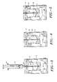
- FIG. 1 is a schematic cross-sectional drawing of a centrifugal separator of this invention with an annular erythrocyte trap
- FIG. 2 is a fragmentary cross-sectional drawing of the centrifugal separator and annular erythrocyte trap shown in FIG. 1
- the separation system comprises a centrifugal separator unit 2 and a motor 4.
- the centrifugal separator unit comprises a centrifugal drum 5 having an inner wall surface 6 with an upper edge 8 and a lower edge 10, a drum bottom 12, and a central axis (not shown).
- the drum bottom 12 has a central depression 14, the bottom 12 constituting a floor sloping downward from the lower edge 10 to the central depression 14.
- the motor 4 has a drive axis 16 that is coaxial with the central axis.
- the motor 4 has the capacity to rotate the centrifugal drum at a speed of at least 2,000 rpm for 120 seconds.
- the complete, self-contained unit includes a battery 18 connected to the motor 4 through conventional power connections, the battery 18 having sufficient capacity to complete the separation process.
- the battery 18 is connected to the motor through an on/off time switch 20 with a manual knob 22.
- An outer container 24 encloses the centrifugal separation unit.
- the container 24 has a top 26 with a sterile syringe port 28 that can be a Luer fitting aligned with the central depression 14.
- An access tube 29 connects to and extends downward from the syringe port 28 into the separation chamber 2. Tube 29 is used for introducing blood into the separation chamber 2 and for removing PRP from the separation chamber 2 as is explained in greater detail with respect to FIGS. 2-6 hereinafter.
- the inner wall surface 6 of the centrifugal drum 5 is sloped outwardly from the bottom 12 at an angle of from 75 to 89° from the central axis.
- the upper edge 8 of the centrifugal drum 5 is surrounded by an outer, annular erythrocyte capture chamber 30.
- the outer container 24 for the system is sealed to maintain sterility.
- a vent system 30 is provided in a wall of the outer container that permits movement of air out of the container when liquid is introduced and movement of air into the container when liquid is removed. Details of suitable venting systems are described hereinafter with respect to FIGS. 2B and 2C .
- the erythrocyte capture chamber 31 includes an outer wall 32, and an inner wall 34, the outer wall 32 having a top edge 36 with an elevation higher than the top 8 of the inner wall 6.
- the vertical distance between the top edge and the top of the inner wall is small, preferably less than 1 mm, but large enough to allow passage of cells, preferably greater than 50 microns.
- the narrow gap between the top of the inner wall and the top of the chamber serves to minimize the sweeping of erythrocytes from the erythrocyte capture chamber into the centrifugal drum by the swirling wave of PRP during deceleration after completion of the centrifugation step.
- the gap above the inner wall can be filled with a depth filter or screen.
- the volume of the erythrocyte capture chamber 31 is sized to retain the total volume of separated erythrocytes and leukocytes in the blood while retaining a minimal volume of PRP.
- An annular cap 38 is secured to the top of the centrifugal drum 5 and the erythrocyte capture chamber 31 in a sealing engagement that prevents escape of blood and blood products from the centrifugal chamber during the centrifugal separation step.
- the upper surface portion 42 of the inner wall 34 of the erythrocyte capture chamber 31 can optionally have a slope forming an angle "a" at least 25° with the central axis, facilitating flow of platelets in the PRP flowing inwardly over the upper edge 8 of the erythrocyte capture chamber 31 when the erythrocytes sediment to fill the erythrocyte capture chamber 31.
- FIG. 1 shows the separation system coupled with a syringe 44 positioned to introduce blood into the separation chamber 2.
- the syringe 44 is shown with the plunger or piston 46 in the extended, full position prior to the blood introduction.
- FIG. 2A is a fragmentary cross-sectional drawing of an alternative erythrocyte trap configuration.
- the upper surface portion 48 of the erythrocyte capture chamber 31 shown in FIG. 2 extends downward to the opposing wall 50, providing a continuous sloped surface for movement of platelets to the centrifugal chamber 5 during centrifugation.
- Surface 48 forms the angle "a" with the central axis (not shown) of the erythrocyte capture chamber.
- FIG. 2B is a detailed fragmentary view of a vent system 30 according to this invention that uses a sterile porous sheet to allow air movement into and from the outer container.
- an air flow passageway 52 in a wall 54 of the outer container 24 ( FIGS. 1 and 2 ) is sealed with a conventional sterile porous sheet 56 that has sufficient porosity to allow free movement of air through the sheet but is an effective microorganism barrier that prevents movement of microorganisms from the outer environment into the container 24. This prevents significant fluctuations of air pressure in the outer container 24 during liquid movement into and out of the system.
- FIG. 2C is a detailed fragmentary view of a vent system 30 according to this invention that uses a flexible balloon or diaphragm to allow air movement into and out of the outer container 24.
- an air flow passageway 58 in a wall 54 of the outer container 24 ( FIGS. 1 and 2 ) is sealed with a balloon or flexible diaphragm 60.
- the balloon or flexible diaphragm 60 should have sufficient flexibility and size to allow free movement of air through the air flow passageway 56 in a volume that can be at least equal to the total volume of blood that is introduced into the system during the separation process. This prevents significant fluctuations of air pressure in the outer container 24 during liquid movement into and out of the system.
- the balloon or flexible diaphragm 60 must have the integrity to an effective microorganism barrier preventing movement of microorganisms from the outer environment into the container 24 during PRP removal.
- FIGS. 3-5 show successive stages in the preparation of PRP with the device of FIG. 1 .
- FIG. 3 is a schematic cross-sectional drawing of the centrifugal separator of FIG. 1 after being loaded with blood 62 from syringe 44.
- Syringe 44 is attached through the Luer port 28 and communicates with the access tube 29, and the plunger 46 has been depressed to expel the blood contents of the syringe into the separation chamber 2.
- FIG. 4 is a schematic cross-sectional drawing of the centrifugal separator of FIG. 1 during the spin separation phase.
- the syringe 44 can be removed as shown, to be replaced with a sterile cap or a fresh syringe to remove separated PRP product.
- the syringe 44 can be left in place during the separation phase (not shown) and reused to remove the PRP product.
- the centrifugal force causes the more dense erythrocytes 64 to move outward through the plasma until they collect in the erythrocyte capture chamber, leaving PRP 66 in the centrifugal drum 5.
- FIG. 5 is a schematic cross-sectional drawing of the centrifugal separator of FIG. 1 after centrifugation has ended.
- the dense erythrocyte layer remains isolated in the erythrocyte capture chamber 30, and the layer of PRP 66 in the centrifugal drum collects at the lowermost section of the centrifugal chamber.
- the PRP can then be removed through the access tube 29 from the centrifugal drum 5 with the original syringe 44 ( FIG. 3 ) or a fresh syringe positioned as shown in FIG. 3 .
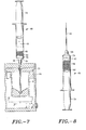
- FIG. 6 is a cross-sectional schematic view of a syringe embodiment for producing PRP concentrate from PRP.
- the syringe device 69 includes a process chamber 70 having an outer wall 72.
- a plunger 74 is positioned above filter 76, the plunger 74 and the filter 76 defining a concentrating portion or chamber 78 of the process chamber 70.
- the concentrator chamber 78 contains concentrating desiccated hydrogel beads 80 and one or more agitators 82.
- a concentrate chamber 84 positioned below or downstream of filter 76, includes an inlet/outlet port 86.
- the concentrating desiccated hydrogel beads 80 can be insoluble beads or disks that will absorb a substantial volume of water and not introduce any undesirable contaminant into the plasma. They can be dextranomer or acrylamide beads that are commercially available (Debrisan from Pharmacia and BIO-GEL PTM from Bio-Rad Laboratories, respectively). Alternatively, other concentrators can be used, such as SEPHADEXTM moisture or water absorbents (available from Pharmacia), silica gel, zeolites, cross-linked agarose, etc., in the form of insoluble inert beads.
- the agitators 82 can be dense objects such as inert metal spheres. It will be readily apparent to a person skilled in the art that the shape, composition and density of the agitators 82 can vary widely without departing from the invention so long as the agitator has a density substantially greater than whole blood. It is advantageous that the agitator be a metal sphere such as a titanium or stainless steel sphere that will not react with blood components, or a dense sphere coated with an inert coating that will not react with blood components.
- the filter 76 can be any inert mesh or porous materials which will permit the passage of plasma and prevent passage of the hydrogel beads and agitator.
- the filter can be a metal wire or inert fiber frit of either woven or nonwoven composition, or any other frit construction which, when the liquid in the concentration chamber is passed through the filter, will permit passage of the PRP and not the hydrogel beads and agitator, effectively separating the PRP from the hydrogel beads and agitators as will be described in greater detail hereinafter.
- FIGS. 7 and 8 show the preparation of PRP concentrate using the syringe concentrator shown in FIG. 6 .
- FIG. 7 is a schematic cross-sectional drawing of the centrifugal separator of FIG. 5 after PRP 66 has been drawn into a concentrator syringe
- FIG. 8 shows a concentrator syringe containing PRP concentrate 90 after the water removal phase.
- Moving plunger or piston 74 draws PRP 66 from the centrifugal drum 5 into the syringe chamber.
- a volume of air is also drawn into the syringe to facilitate expulsion of PRP concentrate after concentration.
- the concentrator syringe is then withdrawn from the centrifugal separator and shaken by a reciprocal movement in the direction of the syringe axis.
- This movement causes relative agitating movement of the agitator balls 82 in the PRP 66, stirring the hydrogel beads in the solution, and mixing the PRP to reduce localized concentrations and gel polarization of plasma proteins around the bead surfaces, thereby facilitating movement of water from the PRP into the beads 80.
- FIG. 8 shows the concentrator syringe with the PRP concentrate 90 after the water removal step is completed.
- FIG. 9 is a schematic cross-sectional drawing of a centrifugal separator of this invention with a depth filter erythrocyte trap.
- This embodiment also comprises a centrifugal separator unit 102 and a motor 104.
- the centrifugal separator unit comprises a centrifugal drum106 having an inner wall surface 108 with a bottom edge 110, a drum bottom 112, and a central axis (not shown).
- the drum bottom 112 has a central depression 114, the bottom 112 constituting a floor sloping downward from the lower edge 110 to the central depression 114.
- the motor 104 has a drive axis 116 coaxial with the central axis.
- the motor 104 has the capacity to rotate the centrifugal drum 102 at a speed of at least 2,000 rpm for 120 seconds with a total power consumption of less than 500 mAh, the power that is obtainable from a small battery such as a conventional 9 volt alkaline battery.
- the complete, self-contained unit includes a battery 118 connected to the motor 104 through conventional power connections.
- the battery 118 has the capacity to provide sufficient power to complete the separation process and being connected to the motor through an on/off toggle or timer switch 120 with a manual knob 122.
- An outer container 124 encloses the centrifugal separation unit.
- the container 124 has a top 126 with a sterile syringe port 128 aligned with the central depression 114, an access tube 130 connected to and extending downward from the syringe port 128 for introducing blood into the separation chamber 132 and for removing PRP from the separation chamber 132 as is explained in greater detail with respect to FIGS. 10-13 hereinafter.
- the inner wall 108 of the centrifugal separator unit 102 is the surface of a depth filter 134 having pores sized to capture erythrocytes moving into the pores during centrifugal separation of the erythrocytes from blood and to retain the erythrocytes in the material of the depth filter when centrifugal separation is completed, the material of the depth filter being selected from a material that does not significantly activate platelets contacting the surface thereof.
- the depth filter 134 can be a honeycomb-like or woven fiber material that allows fluids and small particles to flow freely (e.g., felt or open cell polyurethane foam). Like a wetted sponge, the depth filter holds liquid against a certain head of pressure due to surface tension forces. Thus, blood cells or other suspended particulates remain entrapped within the foam when the centrifuge stops and separated platelet-rich plasma drains from the surface under the force of gravity.
- Foam can be either rigid or flexible and can be formed into the appropriate annular shape for the device by molding or die-cutting. The parts are sized so that the packed cell (e.g., erythrocyte and leukocyte) layer is fully contained within the outer depth filter chamber, which retains the cells when the centrifuge stops.
- erythrocytes moving outward through the plasma during centrifugation pass into and are captured by the depth filter 134, and the PRP flowing downward when centrifugation is ended is substantially free from erythrocytes as is described hereinafter in greater detail with respect to FIGS. 10-13 .
- a vent system136 can be provided in the outer container 124. This vent system can be the same as described hereinabove with respect to Figs. 2B and 2C .
- FIG. 10 is a schematic cross-sectional drawing of the centrifugal separator of FIG. 9 after being loaded with blood 138 from syringe 140, the syringe connecting through the sterile seal 128 and into the vertical tube 130, and the plunger 142 having been depressed to expel the blood contents of the syringe into the separation chamber 132.
- FIG. 11 is a schematic cross-sectional drawing of the centrifugal separator of FIG. 10 during the spin separation phase.
- the syringe 140 can be removed as shown to be replaced with a sterile cap or fresh syringe to remove the separated PRP product.
- the syringe 140 can be left in place (not shown) during the separation phase and used to remove the PRP product.
- the centrifugal force causes the more dense erythrocytes to move outward through the plasma into the depth filter 134, leaving PRP 148 substantially free from erythrocytes in the centrifugal drum 102.
- FIG. 12 is a schematic cross-sectional drawing of the centrifugal separator of FIG. 11 after centrifugation has ended.
- the erythrocyte-free PRP product 148 flows downward in the separator chamber 132, the erythrocytes remaining trapped in the depth filter 134.
- the PRP 148 that collects in the centrifugal drum 102 is substantially free from erythrocytes and leukocytes.
- the PRP 148 can then be removed from the centrifugal drum 102 with the original syringe 140 ( FIG. 10 ) or a fresh syringe as will be readily apparent to a person skilled in the art.
- FIG. 13 is a schematic cross-sectional drawing of the centrifugal separator of FIG. 12 after PRP 148 has been drawn into a concentrator syringe 69. Withdrawing the plunger or piston 74 draws PRP 148 from the centrifugal chamber 132 into the syringe barrel 150.
- the water is removed from the PRP 148 to produce a PRP concentrate and expelled from the syringe as is described hereinabove with respect to FIGs. 7 and 8 .
- FIG. 14 is a schematic representation of a combination centrifugal separator and hollow fiber concentrator of this invention.
- the entire separation and concentration components are enclosed in a housing 160.
- the top of the housing has a sterile vent 162 to allow passage of air displaced during addition and removal of fluid from the device and a Luer fitting 164 to which a standard syringe 166 with a piston 168 and piston actuator 170 can be coupled.
- a centrifugal separator 172 can have the annular erythrocyte trapping system shown and described hereinabove with respect to FIGS. 1-5 or it can have the depth filter erythrocyte trapping system shown and described hereinabove with respect to FIGS. 9-13 .
- a drive motor 174 is positioned in the bottom section of the housing 160 below the centrifugal separator 172 in the basic configurations shown in FIGS. 1 and 9 .
- the concentrator system comprises a hollow fiber cartridge 178 and a pump 180.
- a central tube 182 having outlet 184 extends from the Luer fitting 164 toward the depression 186 at the bottom of the centrifugal separator 172.
- a inlet flow check valve 188 limiting liquid flow toward the centrifugal separator is placed in the central tube 182 at an intermediate level
- the tube outlet 184 is positioned to circulate PRP, preferably stopping short of the bottom 186.
- a return tube 190 extends from the bottom depression 186 to a pump inlet check valve 192 communicating with the inlet of pump 180.
- Check valve 192 directs liquid movement in the direction toward the pump, thus preventing backflow into line 190.
- a second return tube 194 extends from pump outlet check valve 196 communicating with the outlet of pump 180.
- Check valve 196 directs liquid movement in the direction leading away from the pump, thus preventing backflow from line 194 to the pump.
- Second return tube 194 extends to the inlet manifold 198 of the hollow fiber cartridge concentrator 178.
- a third return tube 200 extends from the outlet manifold 202of the hollow fiber cartridge 178 to a concentrator outlet check valve 204 leading to the central tube 182 at a position above (or upstream of) check valve 188.
- Tube 200 is sized to restrict the flow of fluid, generating a backpressure upstream in the fluid circulation path to drive filtration through the hollow fiber membranes.
- Check valve 284 prevents backflow of liquid from the tube
- the hollow fiber cartridge includes fiber membranes that efficiently remove water and salts from the plasma while leaving larger healing factors.
- Choice of the fiber materials and pore distributions is a critical factor because rapid water removal without significant platelet damage must be achieved.
- the large concentration of protein present in plasma presents another difficulty since it thickens along the membrane surface due to localized concentration and gel polarization. Therefore, the fiber membranes and their configuration must facilitate sweeping of the membrane surface by passing plasma, disrupting the polarization and redistributing the plasma constituents.
- the hollow fiber cartridge provide its ultrafiltration function with minimal energy consumption so that complete separation and concentration can be achieved with a standard small (e.g., 9 volt transistor) battery.
- the pump 180 can be a conventional piston or diaphragm pump that provides the necessary circulation of plasma through the hollow fiber separator 316 without use of excessive energy.
- the pump 180 should have the capacity to complete concentration of the plasma with a power consumption of less than 500 mAh, that is, the power available from a small battery such as a standard 9 volt alkaline battery.
- Power to the motor 174 and pump 180 is provided by conventional wiring and a small battery (not shown) that has the capacity to provide sufficient power to complete the concentration process.
- a small (e.g., standard 9 V transistor radio) battery is acceptable.
- a conventional power supply system using standard business and residential power can be used.
- the system shown in FIG. 14 operates as follows: Blood is provided to separator Luer fitting by a blood-filled syringe, using syringe such as syringe 166. Downward movement of the actuator 170 moves the piston 168 in a downward direction, expelling the contents of the syringe through the Luer fitting 164 and the tubing 182 through the inlet check valve 188 into the bottom of the centrifugal separator 172. After its contents have been expelled, the syringe can be left in place or replaced with a fresh syringe or sealing cap to prevent fluid from escaping through the Luer port 164 during the concentrating step of the process.
- Operation of the pump 180 draws PRP from the lower depression 186 of the centrifugal separator upward through tube 190, through the pump inlet check valve 192 into the pumping chamber (not shown) of the pump 180. Then PRP flows through pump 180 and through pump outlet check valve 196. From check valve 194, the PRP passes through the tubing 194 into the inlet manifold 198 of the hollow fiber concentrator 178 and through the hollow fiber concentrator.
- PRP from which a portion of the water and salts have been removed then flows from the outlet manifold 202 of the hollow fiber concentrator 178 through flow restrictive tubing 200 and concentrator outlet check valve 204 to the inlet tubing 182, and then through check valve 188 to the bottom of the centrifugal separator 172 where it mixes with the other PRP. This cycling process is continued, removing a portion of the water in each pass, until the desired concentration of PRP has been obtained.
- PRP erythrocyte removal and concentration of the PRP to a platelet concentration of 3X can be automatically achieved within 5 minutes. If higher PRP concentration is needed for a particular application such as for sealing tissues to stop bleeding, the concentration cycle can be continued beyond 5 minutes, whereby concentration up to 5X and higher can be achieved.
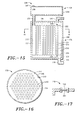
- FIG. 15 is a schematic cross-sectional view of a hollow fiber concentrator shown in FIG. 14
- FIG. 16 is a cross-sectional view of the hollow fiber concentrator of FIG. 15 , taken along the line 16-16.
- the hollow fiber concentrator 178 is combined with an extracted liquid reservoir 206.
- the concentrator 178 has an outer housing 208 that encloses the inlet manifold 198, an outlet manifold 202, a plurality of hollow ultrafiltration fibers 210 and an extracted liquid chamber 212.
- Each of the hollow fibers 210 has a wall 214, an axial passageway 216, an inlet end 218 and an outlet end 220.
- the inlet end 218 of each hollow fiber 210 is secured to a correspondingly sized hole in the inlet manifold plate 222 in a conventional manner that establishes communication between the hollow fiber passageway 216 and the inlet manifold 198 while preventing escape of the liquid contents thereof into the extracted liquid chamber 212.
- each hollow fiber 210 is secured to a correspondingly sized hole in the outlet manifold plate 226 in a conventional manner that establishes communication between the hollow fiber passageway 216 and the outlet manifold 202 while preventing escape of the liquid contents thereof into the extracted liquid chamber 212.
- the extracted liquid chamber 212 is the space defined by the inner wall surface 213 of the housing 208, the outer wall surface of the hollow fibers 210, and the manifold plates 222 and 226.
- the extracted liquid chamber 212 captures the liquid that passes through the hollow fibers 210 in the ultrafiltration process.
- conduit 194 shown in FIG. 14 connects with the inlet manifold 232 through manifold inlet conduit 230.
- the inlet end of conduit 200 shown in FIG. 14 connects with the outlet manifold 202 through manifold outlet conduit 228.
- pressurized plasma passes from conduit 194 through the inlet manifold inlet conduit 230 into the inlet manifold 198, and then through the hollow fibers 210. In each pass a portion of the water and salts passes through the pores in the fiber walls into the extracted liquid chamber 212. The concentrated plasma then passes into the outlet manifold 202, through the outlet manifold outlet conduit 228 and then to the conduit 200.
- the extracted liquid reservoir 206 has a reservoir housing 234 that connects with an overflow conduit 236.
- the overflow reservoir 206 has an air vent 238.
- FIG. 17 is a schematic cross-sectional view of the membrane valve air vent 238 in the hollow fiber concentrator of FIG. 15 .
- the valve 238 comprises a porous lower hydrophilic membrane 240 communicating with the interior of the extracted liquid reservoir 206 and a porous upper hydrophobic membrane 242 that communicates with outer space surrounding the reservoir.
- the extracted liquid reservoir captures extracted liquid when the volume of the extracted liquid exceeds the volume of the extracted liquid chamber 213 and the excess liquid escapes through the extracted liquid conduit 236 into the extracted liquid chamber 206. Air in the extracted liquid chamber displaced by the incoming liquid escapes through the porous membranes 240 and 242 until the liquid level reaches the membranes, saturating the hydrophilic membrane 140. Escape of the extracted liquid from the extracted liquid chamber 206 is prevented by the hydrophobic membrane 242.
- the valve prevents movement of air into the system when PRP concentrate is removed as follows. Movement of PRP concentrate from the centrifugal separator 172 ( FIG. 14 ) creates a partial vacuum in the system. Movement of air through the valve 238 in response to this partial vacuum is prevented by the liquid saturated hydrophilic membrane 240.
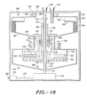
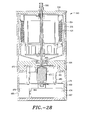
- Fig. 18 is a schematic cross-sectional drawing of an automated spring-clutch system for preparing PRP concentrate from a patient's blood.
- the disposable, single-use system is enclosed in a compact portable device that can be smaller than a twelve ounce soft drink can.
- the outer housing 252 is sealed except for the blood inlet port 254, the PRP concentrate withdrawal port 256, and sterile vent 258.
- the PRP withdrawal port 256 is one end of a rigid PRP concentrate withdrawal tube 260 that is secured to the outer housing 252 and functions as a central axle around which the rotary separation components turn and also as a PRP concentrate withdrawal tube.
- the separation components comprise a upper rotary centrifugal separator housing 262 and a lower rotary water removal system housing 264, these two housing being connected by an integral cylindrical waist element 266 into a unitary housing structure.
- the water removal system housing 264 includes a PRP concentrate reservoir 268 that communicates with the lower opening 270 of the PRP concentrate withdrawal tube 260.
- the rotary components are supported on the drive axle 272 of the two direction, two speed motor 274.
- the direction and speed of the motor 274 are controlled by the conventional motor controller 276 to which it is connected by electrical conduit 278.
- Switch 280 activates the motor controller 276.
- roller bearing raceway structure that includes a plurality of roller bearings 282 positioned between an outer ring flange 284 secured to the outer housing 252 and an inner ring flange 286 secured to the upper rotary centrifugal separator housing 262.
- the centrifugal blood separating components housed in the upper housing 262 of the rotary assemblage is similar in structure and function to other blood separators described hereinabove with respect to FIGs. 9-13 in that the cylindrical rotary centrifugal separator 290 has the inner surface of its outer wall lined with a cylindrical depth filter 294. Also included in this embodiments of the centrifugal separator is an blood overflow reservoir 296 defined by a floor 298 and an integral wall 300 that functions to control or limit the volume of blood that is subject to the separating operation if the volume introduced exceeds the volume that can be effectively concentrated in the water removal operation described in greater detail hereinafter.
- the centrifugal separator spins during the separation phase, excess blood flows upwardly along the wall 300 and into the PRP reservoir 296.
- the wall 300 prevents escape of liquid as it settles on the floor 298.
- Suitable depth filter materials have been described hereinabove with respect to FIGs. 9-13 .
- the depth filter structure and overflow reservoir structure 294 can be replaced with an erythrocyte trap and function such as is described with respect to FIGs. 1-8 hereinabove in a manner that would be readily apparent to a person skilled in the art.
- erythrocytes separating from the plasma flow into the depth filter 294, leaving a layer of PRP behind outside the depth filter.
- the PRP flows to the bottom of the centrifugal separator where it is held by the seal of the valve plate 302 against the floor 304 of the separation housing.
- valve plate 302 The seal of the valve plate 302 against the floor 304 is opened by action of a spring clutch assembly.
- the valve plate 302 is a part of a valve assembly including a hollow upper valve stem 306 (a cylinder) integral with the plate 302 through which the rigid tube 260 extends. This stabilizes orientation of the valve assembly on the rigid tube 260.
- the lower part of the valve assembly is outer cylinder 308 with internal threads 310.
- the outer cylinder 308 further encloses an inner cylinder 312 that has external threads 314 engaging the internal threads 310 of the outer cylinder 308 in sliding engagement.
- the spring clutch 288 wraps around the rigid tube 260 and is positioned between the rotary internal threaded element 312 to which it is secured and the rigid tube 260.
- the spring clutch 288 functions as a slip bearing between the rotating internal threaded element 312 and the rigid tube 260 during the centrifugal separation phase because the direction of the movement of the spring around the stationary rod 260 tends to open the spring, reducing then sliding friction.
- the motor 274 is then activated to turn slowly in a reverse direction.
- the spring-clutch 288 rotates around the rigid tube 260 in a direction that tightens the spring, locking the spring to the rigid tube 260.
- the outer cylinder 308 rises, lifting unseating the valve plate 306, the movement continuing until the top surface 318 of the upper valve stem 306 abuts the collar 318 secured to the rigid tube 260.
- the PRP in the bottom of the centrifugal separator 290 flows downward through a channel 320 defined by the outer surface 322 of the lower cylinder and the inner surface 324 of the waist cylinder 266 into the lower rotary water removal system enclosed in the lower housing 264 where it contacts the desiccated gel beads 326. Direct flow of liquid from the water removal system is prevented by O-ring seal 327.
- the lower rotary water removal system 328 enclosed in lower housing 264 comprises a rotary cylindrical screen element 330 which has radially inwardly extending comb elements 332 and a rake system.
- the bottom of the lower housing 264 has a central opening with a downwardly extending cylindrical flange 333 to accommodate the rigid tube 260.
- O-ring 327 is positioned between flange 333 and the rigid tube 260 to prevent liquid flow therebetween.
- the rake system comprises a rake cylinder 334 having radially outward extending rake elements 336 that mesh with the comb elements 332.
- the rake cylinder 334 is separated from the rigid tube 260 by roller bearings 338 that reduce friction between the rake cylinder 334 and the tube 260 during the high speed rotation of the centrifugation step.
- the rake cylinder has a projecting spline 340 that engages a matching vertical recess grove (now shown) in the lower valve stem 308.
- the spline 340 is positioned to move up and down in the matching grove to maintain engagement of the rake cylinder 334 and the lower valve stem outer cylinder 308 at all elevations of the valve stem.
- the spline system locks the rake cylinder 334 to the stationary tube 260 when the spring clutch engages, preventing rotation of the rake cylinder when the comb elements are rotated through the rakes.
- the motor controller 276 can reverse rotational direction of the drive shaft 272, causing disengagement of the spring clutch 288 from the rigid tube 260, and permitting the separation assembly elements to rapidly spin as a unit.
- the concentrated PRP is spun from the beads 270 through the cylindrical screen 330 where it is collected in the PRP concentrate reservoir 268.
- PRP concentrate is then drawn from the PRP concentrate reservoir 268 though the rigid tube 260 and out through the PRP concentrate withdrawal port 256.
- Fig. 19 is an isometric view of a plasma separator and concentrator embodiment of this invention
- Fig. 20 is a top view of the plasma separator and concentrator shown in Fig. 19
- This embodiment comprises a disposable separator/concentrator module 350 and a permanent base 352 with the motor and control system.
- the separator/concentrator module 350 has a housing 354 and a housing top 356.
- the housing top 356 has a blood inlet port 358 and a plasma concentrate outlet port 360.
- the base 352 has a base housing 362 with a control switch 364 and an external power connector 366 ( Fig. 20 ).
- This compact unit separates platelet rich plasma (PRP) from blood and removes water from the PRP to form an autologous platelet rich plasma concentrate from a patients blood within minutes.
- PRP platelet rich plasma
- Fig. 21 is a cross-sectional view of the plasma separator and concentrator of Fig. 20 , taken along the line 21-21, separated along the vertical axis to show the motor drive and drive receptor relationship prior to placing the disposable separator-concentrator assembly on the drive base.
- the drive base 368 comprises a base housing 370 supported on a plurality of base feet 372.
- the housing has a rotary assembly guide surface 374 that is shaped to match the shape of the base receptor 376 of the separator and concentrator assembly 350. It has an annular support surface 380 that together with the top support surface 382 supports and aligns the separator and concentrator assembly 350 on the base 368.
- a motor 384 is mounted on a support plate 386 that is held in position by a plurality of support fixtures 388.
- the motor 384 has a drive connector 390 that securely mates with the rotary assembly drive receptor 392.
- the base has a conventional power connector 366 and a conventional motor control switch 364 that are electrically connected to the motor with conductors in a conventional manner (not shown).
- the motor control switch 364 includes a conventional timer that controls the motor speed at different phases of the separation and concentration process as is described in greater detail hereinafter.
- the rotary unit comprises the housing 354 with the housing top 356 supporting the PRP concentrate outlet port 360.
- the housing 354 includes a base 394 with a base receptor 376 that is shaped and sized to mate with the top support surface 374 and assembly guide to support and align the separator and concentrator assembly 350 on the base 374.
- Axially concentric bearing assembly 396 is positioned to support the separator and concentrator assembly 350 in position to permit mating of the drive connector 390 and the drive receptor 392.
- the drive connector 390 and drive receptor 392 have matching shapes that require the two units to turn a single unit. They can have any cross-sectional shape that prevents the drive connector 390 from turning inside the drive receptor 392 such as the rectangular shape shown. It can also have any other polygonal or oval shape that provides this result. Circular cross-sections are also acceptable if they are keyed in a conventional manner fully within the skill of the art, and all functionally equivalent shapes are intended to be within the scope of this invention.
- the separation and concentration assembly 378 rotates about the vertical axes established by the stationary fixed tube 398.
- Tube 398 also constitutes a PRP concentrate conduit. This communicates with the PRP concentrate outlet 360.
- Tube 398 is rigidly secured against rotation about its central axis by its connection with the top 356 of the outer housing 354.
- the lower end 398 of the tube 398 includes a PRP concentrate inlet 400 and a rake hub 402 that is rigidly connected to the tube so that it remains stationary when the rotary components are in motion as will be described in greater detail hereinafter.
- the separation and concentration assembly 378 includes a rotary housing 378, the tapered bottom 404 of which includes the drive receptor 392.
- the separation and concentration assembly 378 has a top plate 406 with a sterile vent 408 that is supported in its position on the tube 398 by sleeve bearing 410.
- Figs. 21-23 The desiccated gel beads used to removed water from the PRP are omitted from Figs. 21-23 to present more clearly the other components of the concentrating assembly. They are shown in Figs. 24-27 .
- the separation and concentration assembly 378 has an outer wall 412 that isolates the blood components during the separation and concentrating process.
- the upper portion of the housing 378 encloses a centrifugal plasma separator that comprises a cylindrical blood reservoir 416 with an outwardly tapering inner surface 418 and an inner wall 420 that surrounds the tube 398 and is configured to permit free rotation of the inner wall 420 around the tube 398. This combination maintains axial orientation of the blood reservoir during centrifugal motion of the separation process.
- a cylindrical depth filter 424 Surrounding the blood reservoir 416 is a cylindrical depth filter 424 above which is positioned an annular blood overflow reservoir 426, details and functions of which are described in greater detail hereinbelow with respect to Fig. 23 .
- a concentrator assembly 428 is positioned below the blood reservoir 416 and depth filter 424.
- the concentration assembly comprises a concentrating basket 429 formed by an axially concentric rotary screen 430 and a concentrator base 432.
- the screen has a cylindrical cross-section and is supported by a circular array of vertical supports 434.
- Surrounding the screen 430 is a concentric PRP concentrate reservoir comprising a vertical side wall 438 and the tapered bottom 404. The center of the tapered bottom 404 is positioned adjacent the inlet opening 400 of the tube 398.
- Fig. 22 is a cross-sectional view of the plasma separator and concentrator of Fig. 20 , taken along the line 22-22 and should be considered together with Figs. 21 and 23 to form a complete understanding of the structure of the invention.
- the view provided by this figure shows, in addition to features described above with respect to Fig. 21 , a cross-sectional view of the blood inlet 358 supported by the housing top 356 and the rake elements 440 mounted on the rake hub 402.
- Fig. 23 is a fragmentary cross-sectional view of the separator-concentrator shown in Fig. 22 .
- a top plate 442 is secured to the top of the outer wall 412 to confine the blood to the separator during the centrifugal separation.
- the top plate 442 supports a blood distribution tube 444 that is positioned below and in alignment with the blood inlet port 358 at the first stage when blood is introduced into the separator.
- the annular blood overflow chamber 426 has a top plate 446 with a blood flow inlet opening 448 adjacent the top plate 442 and a second vent opening 450 that is radially inward from the blood inlet opening. This allows overflowing blood to enter the chamber during the centrifugal separation phase through the first inlet opening 448 and allows escape of air displaced by the blood through the second vent opening 450.
- the tapered outer wall 418 of the blood reservoir has a tip edge 449.
- a PRP flow passageway 451 leads from the outer separation chamber 453 to the concentrator basket 429.
- the rakes 440 have a terminal tip edge 452 that are positioned adjacent the inner surfaces 454 of the upright screen supports 434 so they closely sweep the surfaces 454 during their rotation.
- the upright screen supports 434 have a thickness and openings 456 into which gel beads collect during the fast centrifuge phase, placing them beyond the tip edge of the rakes.
- the screen 430 has a mesh size that is sufficiently small to prevent escape of the gel beads from the chamber concentration chamber during the final centrifugal separation of the PRP concentrate from the gel beads.
- Figs. 24-27 illustrate the device of Figs. 19-23 during the phases of the blood separation and concentration.
- Fig. 24 is a cross-sectional drawing of the device of Figs. 19-23 after blood has been added
- Fig. 25 is a cross-sectional drawing of the device during the centrifugal separation stage producing PRP
- Fig. 26 is a cross-sectional drawing of the device during the slow rotation concentration stage
- Fig. 27 is a cross-sectional drawing of the device of during the centrifugal PRP concentrate separation stage.
- the blood separation and concentration with the device of this invention proceeds as follows:
- the motor 384 is energized to rotate the separator and concentrator assembly 378 at a fast spin rate that effects centrifugal separation of the more dense erythrocytes in the blood from the PRP.
- the central tube 360 and attached rake 440 remain stationary during this rapid rotation, and the gel beads 460 are spun by the rotary components and held by the centrifugal force against the screen 430, beyond the reach of the tips 452 of the stationary rake tips 440.
- the centrifugal force causes the blood 458 to flow up the tapered inside wall 418 of the blood reservoir 416 and over the tip edge 449, to collect against the depth filter 424 as shown in Fig. 25 .
- the separation is achieved as a function of cell density, sending the most dense erythrocytes outward and through the passageways of the depth filter 424.
- the platelets remain in the PRP layer 462 that forms against the depth filter 424.
- PRP flow passageways 451 lead from the outer separator chamber 453 to the concentrator basket 429.
- the PRP 462 flows from the pores and surface of the depth filter 424 downward through the PRP flow passageway 451 into the concentrating basket 429. Erythrocytes remain trapped in the pores and passageways of the depth filter 424 so that the PRP 463 reaching the basket 429 is substantially free of erythrocytes.
- the PRP 463 flows into contact with the desiccated gel beads 460 that have collected on the base 432 of the concentrating basket 429. As the beads absorb water from the PRP, they swell, and the PRP immediately adjacent the bead surface thickens and becomes tacky. The continuing slow movement of the concentration basket 429 past the stationary rake 440 and the vertical supports 434 stirs the beads 460, reducing gel polarization on the bead surface, and breaking up the bead clumps. This slow stirring movement of the rotary components is continued until the water removal stage is completed.
- the motor speed is then increased to a fast spin mode, and the centrifugal force moves the gel beads 460 to the surface of the screen 430.
- the centrifugal force generated by the spin caused the PRP concentrate 464 to flow away from the surfaces of the beads and through the screen 430 to collect the PRP concentrate in the PRP reservoir as shown in Fig. 27 .
- the PRP concentrate is removed with a syringe through tube 398 and PRP outlet port 360.
- Fig. 28 is a cross-sectional view of a portable embodiment of this invention.
- This embodiment includes a blood separation and concentration system in the upper housing 354 that is identical to the blood separation and concentration system described with respect to Figs. 19-23 . Because these components are identical and to avoid unnecessary redundancy, no separate description of the identical components is provided herein, the description of these elements with respect to Figs. 19-27 being incorporated by reference. For details about the blood separation and concentration systems, see the description of the components provided hereinabove with respect to Figs. 19-23 .
- the system shown in Figs. 19-23 comprises a disposable blood separation and concentration unit and a permanent motor control unit. This assembly is optimum of use in a laboratory or surgical setting found in a hospital or medical clinic.
- a portable fully integrated embodiment of this invention is provided.
- the major difference between the embodiment shown in Fig. 24 is the integration of the motor, power supply and control system in a unitary system with the blood separation and concentration system.
- the lower casing or housing 470 encloses the motor 472, power supply 474 and control system 476.
- the motor 472 is secured to a motor support plate 478 mounted on the motor support suspension 480.
- the motor support suspension 480 is secured the lower surface 482 of the base 484 in a position to maintain axial alignment of the motor with the axis of the rotary elements of the separator and concentrator unit.
- the motor drive shaft is secured to the separator and concentrator assembly by a coupling 485.
- the motor 472 is connected to the battery power supply 474 and control system 476 with conventional electrical circuitry (not shown).
- the battery power supply is electrically connected to the control system 476 with conventional electrical connections 486.
- a conventional removable plate 487 can be removably secured to the lower portion of the lower housing 489 in a position that permits insertion of the power supply battery 474 when it is removed. This allows insertion of an active battery immediately before deployment or use of the system.
- the control system 476 is a conventional motor controller and timer that establishes and controls the motor speeds during the rapid rotation centrifugation phases of the blood separation and during the concentration stages, and during the slow rotation concentration stage. These stages are the same as are described hereinabove with respect to Figs. 24-27 .
- the weight and size of the separator and concentrator elements are selected to conserve energy and to be fully operational with a standard 9 volt battery. This enables the device to be a completely portable system that does not require external power. It is thus suitable for use in mobile field units and field hospitals where self-powered, fully portable units are needed.
Abstract
Description
- This invention relates to a device and method for preparing platelet-plasma concentrates with improved wound healing properties for use as a tissue sealant and adhesive. The product has a fully active (un-denatured) fibrinogen concentration that is several times greater than is found in blood and a platelet concentration that is many times greater than is found in blood.
- Blood can be fractionated, and the different fractions of the blood can be used for different medical needs. Under the influence of gravity or centrifugal force, blood spontaneously sediments into three layers. At equilibrium, the top low-density layer is a straw-colored clear fluid called plasma. Plasma is a water solution of salts, metabolites, peptides, and many proteins ranging from small (insulin) to very large (complement components).
- The bottom, high-density layer is a deep red viscous fluid comprising anuclear red blood cells (erythrocytes) specialized for oxygen transport. The red color is imparted by a high concentration of chelated iron or heme that is responsible for the erythrocytes' high specific gravity. The relative volume of whole blood that consists of erythrocytes is called the hematocrit, and in normal human beings this can range from about 37% to about 52% of whole blood.
- The intermediate layer is the smallest, appearing as a thin white band above the erythrocyte layer and below the plasma layer; this is called the buffy coat. The buffy coat itself has two major components, nucleated leukocytes (white blood cells) and anuclear smaller bodies called platelets (or thrombocytes). Leukocytes confer immunity and contribute to debris scavenging. Platelets seal ruptures in blood vessels to stop bleeding, and deliver growth and wound healing factors to a wound site. Slower speed or shorter duration centrifugation permits separation of erythrocytes and leucocytes from plasma, while the smaller platelets remain suspended in the plasma, resulting in PRP.
- A major improvement in making plasma concentrate from whole blood for use in wound healing and as a tissue sealant is described in
U.S. Patent No. 5,585,007 ; this patent is hereby incorporated by reference in its entirety. This device, designed for placement in a medical laboratory or surgical amphitheatre, used a disposable cartridge for preparing tissue sealant. The device was particularly applicable for stat preparations of autologous tissue sealants. Preparation in the operating room of 5 ml of sealant from 50 ml of patient blood required less than 15 minutes and only one simple operator step. There was no risk of tracking error because processing can be done in the operating room. Chemicals added could be limited to anticoagulant (e.g., citrate) and calcium chloride. The disposable cartridge could fit in the palm of the hand and was hermetically sealed to eliminate possible exposure to patient blood and ensure sterility. Adhesive and tensile strengths of the product were comparable or superior to pooled blood fibrin sealants made with precipitation methods. Use of antifibrinolytic agents (such as aprotinin) was not necessary because the tissue sealant contained high concentrations of natural inhibitors of fibrinolysis from the patient's blood. This new tissue sealant also optionally contained patient platelets and additional factors that promote wound healing, healing factors that are not present in commercially available fibrin sealants. - This device used a new sterile disposable cartridge with the separation chambers for each run. Since the device was designed to be used in a normal medical setting with ample power, the permanent components, designed for long-term durability, safety and reliability, were relatively heavy, using conventional centrifuge motors and accessories.
- Small, self-contained centrifugal devices for obtaining platelet concentrates from blood are described in commonly assigned, copending application Serial No.
10/394,828 filed March 21, 2003 - It is an objective of this invention to provide a compact, self-contained system for producing a concentrate of platelets suspended in concentrated fully active plasma, that is substantially unactivated platelets suspended in plasma concentrated by removing water, leaving the fibrinogen in a fully active form.
- The PRP separator-concentrator of the present invention is suitable for office use or emergency use for trauma victims.
- One embodiment is a disposable self-contained PRP separator and concentrator unit designed for use with a permanent motor assembly.
- Another embodiment is a self-contained disposable PRP separator and concentrator that includes an internal motor and power supply assembly.
- A still further embodiment comprises a motorized centrifugal separation unit for preparing PRP.
- The PRP separator comprises a motorized centrifugal separation assembly for and an optional concentrator assembly for concentrating the PRP. The centrifugal separator assembly comprises a centrifugal drum separator that includes an erythrocyte capture module and a motor with a drive axis connected to the centrifugal drum separator. The concentrator assembly comprises a water-removal system for preparing PRP concentrate.
- The centrifugal drum can have an inner wall surface with an upper edge and a lower edge, a drum bottom, and a central axis; the drum bottom can have a central depression and a floor sloping downward from the lower edge to the center of the central depression.
- In the portable, self-contained embodiment of the PRP separator-concentrator of this invention, the motorized centrifugal separation assembly includes a motor having a drive axis, the drive axis being coaxial with the central axis. The motor can have the capacity to rotate the centrifugal drum at a speed of at least 2,000 rpm for 120 seconds. The battery can be connected to the motor through an on/off switch or timer switch, the battery having the capacity to provide sufficient power to complete the separation process. The portable centrifugal separator can be fully enclosed within an outer container, the outer container having a top with a sterile syringe port aligned with the central depression, and an access tube connected to and extending downward from the syringe port.
- In one embodiment, the erythrocyte capture module is a depth filter lining the inner wall surface of the centrifugal separator unit, the depth filter having pores sized to capture erythrocytes moving into the pores during centrifugal separation of the erythrocytes from blood and to retain the erythrocytes in the depth filter when centrifugal separation is completed. The term "depth filter", as used herein, is defined as a filter medium that retains contaminants primarily within tortuous passages. It can include an open-cell foam or other matrix made of a material such as a felt that does not significantly activate platelets contacting the surface thereof, whereby erythrocytes moving outward through the plasma during centrifugation move into and are captured by the depth filter leaving behind PRP substantially free from erythrocytes.
- In an alternative embodiment of the invention, the inner wall surface of the centrifugal drum can be sloped outwardly from the bottom at an angle of from 1° to 15° with respect to the central axis. The upper edge of the centrifugal drum can be surrounded by an outer, annular erythrocyte capture chamber, the erythrocyte capture chamber including, an outer wall and an inner wall, the outer wall having an upper edge with an elevation higher than the inner wall. The volume of the erythrocyte capture chamber below the top of the inner wall is sized to retain the total volume of separated erythrocytes in the blood while retaining a minimal volume of the PRP. In this embodiment, erythrocytes moving outward through the plasma during centrifugation are retained against the outer wall of the erythrocyte capture chamber and slide downward to substantially fill the lower volume of the erythrocyte capture chamber when centrifugation is ended. During centrifugation, platelets suspended in the liquid in the erythrocyte capture chamber are carried with the flow of plasma displaced by sedimenting erythrocytes so that they travel to the top and over the inner surface of the erythrocyte capture chamber and into the centrifugal drum. Optionally, at least the upper surface of the inner wall of the erythrocyte capture chamber has a slope forming an angle "a" of at least 25° with respect to the central axis for facilitating flow of platelets against the centrifugal force up and over the upper edge of the erythrocyte capture chamber during centrifugation. As the plasma flows from the erythrocyte capture chamber to the centrifugal chamber, the portal or cross-sectional area through which the plasma flows is reduced by the rising slope of the inner wall surface, causing an increase in the plasma flow velocity over the surface and increasing the portion of platelets successfully transported by the plasma.
- In one embodiment, the concentrator assembly of the PRP separator-concentrator includes a water-removing hollow fiber cartridge, a pump, and tubing connecting with the hollow fiber cartridge and the pump that circulates PRP in the centrifugal drum through the pump and hollow fiber cartridge and then returns it to the centrifugal drum. In the hollow fiber cartridge, the fibers are ultrafiltration membranes with pores that allow the flow of water through the fiber membrane while excluding the passage of growth factors helpful for healing. The pore structure and surfaces are selected to avoid activation of platelets and disruption of any erythrocytes remaining in the PRP.
- In another embodiment, the concentrator assembly includes a plasma concentrating syringe, the syringe having a Luer coupling for connection to the access tube to the center or central depression of the centrifugal drum. In this embodiment, the plasma concentrating syringe comprises a cylindrical barrel with an inner surface and an inlet/outlet port, and a cylindrical actuated piston having an outer surface engaging the inner surface of the barrel. Concentrating beads which can be desiccated hydrogel are positioned between the piston and the inlet/outlet port. A filter is positioned adjacent the inlet/outlet port to prevent escape of the concentrating beads through the inlet/out port. In the operation of the syringe concentrator, movement of the piston in a direction away from the inlet/outlet port draws PRP into the concentrating chamber. Water is removed from the PRP by the concentrating beads, thereby concentrating the PRP without activating the platelets or denaturing the fibrinogen in the plasma. Movement of the piston toward the inlet/outlet port expels concentrated PRP through the inlet/outlet port.
- Because the devices of this invention can be operated with standard batteries as their power source, they consume far less power than prior art centrifuge devices, leading to substantial power saving.
- A further PRP separator and concentrator embodiment of this invention has a central axis comprises a stationary housing and a rotary assembly mounted for rotation about the central axis with respect to the stationary housing. The rotatable assembly comprises a rotatable centrifugal separator and concentrator and a drive motor. A coupling connects the drive motor and the rotatable assembly, the motor and drive coupling being positioned to rotate the rotatable assembly about the central axis.
- The centrifugal separator has an inner separation chamber and an outer erythrocyte capture system. The concentrator comprises a concentration chamber containing desiccated beads. The concentration chamber comprises a floor and a plurality of upright screen supports, the upright screen supports having an inner surface and an outer surface. A cylindrical screen is supported on the outer surface of the upright screen supports.
- An axially concentric stationary tube is secured to the housing and extends through the concentration chamber. A stationary bead rake is secured to the tube and extends radially outward. The rake has a distal edge that is positioned adjacent the inner surface of the upright screen supports,
- With this assemblage, slow rotation of the rotary assembly with respect to the stationary housing pulls the beads past the stationary rake, reducing gel polarization and clumping of the beads.
- Each pair of adjacent upright screen supports can define a desiccating bead receptor for holding desiccated beads radially outward from the distal edge of the rake, whereby bead disruption by the rake during high speed rotational phases is substantially avoided.
- The separator and concentrator can include a motor controller, wherein the drive motor has a high rotational speed required for centrifugal separation and PRP collection phases and a slow rotational speed required for water removal by desiccated beads, the motor controller include a switch for initiating high and low rotational speeds of the rotary assembly.
- The switch initiates high rotational speed of the rotary assembly during centrifugal and PRP concentrate collection phases and initiates low slow rotational speed of the rotary assembly during the PRP concentrate collection phase.
- Another rotatable PRP concentrator of this invention has a stationary housing with a central axis, the concentrator including a drive motor and a coupling connecting the drive motor and the centrifugal separator for rotation about its central axis. The concentrator comprises a concentration chamber containing desiccated beads, the concentration chamber comprising a floor and a plurality of upright screen supports. The upright screen supports have an inner surface and an outer surface. A cylindrical screen is supported on the outer surface of the upright screen supports. An axially concentric stationary tube secured to the housing extends through the concentration chamber. A stationary bead rake is secured to the tube and extends radially outward to adjacent the inner surface of the upright screen supports.
- With this configuration, slow rotation of the rotary assembly with respect to the stationary housing pulls the beads past the stationary rake, reducing gel polarization and clumping of the beads.
- Each pair of adjacent upright screen supports and the screen segments extending therebetween defines a desiccating bead receptor for holding desiccated beads radially outward from the distal edge of the rake, whereby bead disruption by the rake during high speed rotational phases is substantially avoided.
- The separator and concentrator can include a motor controller, wherein the drive motor has a high rotational speed required for the PRP collection phase and a slow rotational speed required for water removal by desiccated beads. The motor controller includes a switch for initiating high and low rotational speeds of the rotary assembly. The switch initiates high rotational speed of the rotary assembly during the PRP concentrate collection phase and initiates low slow rotational speed of the rotary assembly during the PRP concentrate collection phase.
- A more complete appreciation of the invention and many of the attendant advantages thereof will be readily obtained as the same becomes better understood by reference to the following detailed description when considered with the accompanying drawings, wherein:
-
FIG. 1 is a schematic cross-sectional drawing of a centrifugal separator of this invention with an annular erythrocyte trap. -
FIG. 2 is a fragmentary cross-sectional drawing of the centrifugal separator and annular erythrocyte trap portion of the centrifugal separator shown inFIG. 1 . -
FIG. 2A is a fragmentary cross-sectional drawing of an alternative erythrocyte trap. -
FIG. 2B is a detailed fragmentary view of a vent system according to this invention that uses a sterile porous sheet to allow air movement into and from the outer container. -
FIG. 2C is a detailed fragmentary view of a vent system according to this invention that uses a flexible balloon or diaphragm to allow air movement into and from the outer container. -
FIG. 3 is a schematic cross-sectional drawing of the separation separator ofFIG. 1 after being loaded with blood. -
FIG. 4 is a schematic cross-sectional drawing of the separation separator ofFIG. 1 during the spin separation phase. -
FIG. 5 is a schematic cross-sectional drawing of the separation separator ofFIG. 1 after centrifugation has ended. -
FIG. 6 is a cross-sectional drawing of a concentrator syringe. -
FIG. 7 a schematic cross-sectional drawing of the separation separator ofFIG. 1 after PRP has been drawn into a concentrator syringe. -
FIG. 8 shows a concentrator syringe containing PRP after the water removal phase with the PRP concentrate ready for use. -
FIG. 9 is a schematic cross-sectional drawing of a separation separator of this invention with a depth filter erythrocyte trap. -
FIG. 10 is a schematic cross-sectional drawing of the separation separator ofFIG. 9 after being loaded with blood. -
FIG. 11 is a schematic cross-sectional drawing of the separation separator ofFIG. 10 during the spin separation phase. -
FIG. 12 is a schematic cross-sectional drawing of the separation separator ofFIG. 10 after centrifugation has ended. -
FIG. 13 is a schematic cross-sectional drawing of the separation separator ofFIG. 9 after PRP has been drawn into a concentrator syringe. -
FIG.14 is a schematic representation of a combination centrifugal separator and hollow fiber concentrator of this invention. -
FIG. 15 is a schematic cross-sectional view of a hollow fiber concentrator according to this invention. -
FIG. 16 is a cross-sectional view of the hollow fiber concentrator ofFIG. 15 , taken along the line 16-16. -
FIG. 17 is a schematic cross-sectional view of the membrane valve in the hollow fiber concentrator ofFIG. 15 . -
FIG. 18 is a schematic cross-sectional drawing of an automated spring-clutch system for preparing PRP concentrate from a patient's blood. -
Fig. 19 is an isometric view of a plasma separator and concentrator embodiment of this invention. -
Fig. 20 is a top view of the plasma separator and concentrator shown inFig. 19 . -
Fig. 21 is a cross-sectional view of the plasma separator and concentrator ofFig. 20 , taken along the line 21-21, exploded along the vertical axis to show the motor drive and drive receptor relationship prior to placing the disposable separator-concentrator assembly on the drive base. -
Fig. 22 is a cross-sectional view of the plasma separator and concentrator ofFig. 20 , taken along the line 22-22. -
Fig. 23 is a fragmentary cross-sectional view of the separator-concentrator shown inFig. 22 . -
Fig. 24 is a cross-sectional drawing of the device ofFigs. 19-23 after blood has been added. -
Fig. 25 is a cross-sectional drawing of the device ofFigs. 19-23 during the centrifugal separation stage producing PRP. -
Fig. 26 is a cross-sectional drawing of the device ofFigs. 19-23 during the slow rotation concentration stage. -
Fig. 27 is a cross-sectional drawing of the device ofFigs. 19-23 during the centrifugal PRP concentrate separation stage. -
Fig. 28 is a cross-sectional view of a portable embodiment of this invention. - This device and method separates plasma-rich plasma from blood and removes water from the plasma-rich plasma without denaturing the fibrinogen or activating the platelets invention. One aspect of the invention is a portable, completely self-contained device that performs this method with a patient's blood to provide an autologous product that is useful as wound healing tissue sealant and adhesive that promotes and speeds healing. Another aspect of the invention is a portable disposable system that can be used with a permanent motorized unit to provide this method and product. A still further aspect is a portable disposable system for producing PRP from a patient's blood.
- The devices of this invention are small, portable, self-contained, disposable PRP separation systems. The centrifugal separation modules described with respect to
FIGS. 1-13 are one aspect of this invention. They are directed to disposable PRP separation systems that can be used by a medical assistant or doctor without extensive training to prepare PRP and a PRP concentrate from a patient's blood within minutes, with a high recovery of platelets and without significant activation of the platelets. The devices are completely automated and require no user intervention between, first, loading and actuating the device and, second, retrieving the PRP. The devices are able to process bloods of different hematocrits and different plasma densities. - Another more highly automated separator-concentrator of this invention is the combination centrifugal separator and hollow fiber cartridge concentrator shown in
FIG. 14 . This system requires no user intervention between loading the blood and retrieving PRP concentrate. -
FIG. 1 is a schematic cross-sectional drawing of a centrifugal separator of this invention with an annular erythrocyte trap, andFIG. 2 is a fragmentary cross-sectional drawing of the centrifugal separator and annular erythrocyte trap shown inFIG. 1 . Referring toFIGS. 1 and2 , the separation system comprises acentrifugal separator unit 2 and amotor 4. The centrifugal separator unit comprises acentrifugal drum 5 having aninner wall surface 6 with anupper edge 8 and alower edge 10, a drum bottom 12, and a central axis (not shown). The drum bottom 12 has acentral depression 14, the bottom 12 constituting a floor sloping downward from thelower edge 10 to thecentral depression 14. Themotor 4 has adrive axis 16 that is coaxial with the central axis. Themotor 4 has the capacity to rotate the centrifugal drum at a speed of at least 2,000 rpm for 120 seconds. - The complete, self-contained unit includes a
battery 18 connected to themotor 4 through conventional power connections, thebattery 18 having sufficient capacity to complete the separation process. Thebattery 18 is connected to the motor through an on/offtime switch 20 with amanual knob 22. - An
outer container 24 encloses the centrifugal separation unit. Thecontainer 24 has a top 26 with asterile syringe port 28 that can be a Luer fitting aligned with thecentral depression 14. Anaccess tube 29 connects to and extends downward from thesyringe port 28 into theseparation chamber 2.Tube 29 is used for introducing blood into theseparation chamber 2 and for removing PRP from theseparation chamber 2 as is explained in greater detail with respect toFIGS. 2-6 hereinafter. - The
inner wall surface 6 of thecentrifugal drum 5 is sloped outwardly from the bottom 12 at an angle of from 75 to 89° from the central axis. Theupper edge 8 of thecentrifugal drum 5 is surrounded by an outer, annularerythrocyte capture chamber 30. - Preferably, the
outer container 24 for the system is sealed to maintain sterility. To prevent pressure fluctuations from movement of liquid into and from the system, avent system 30 is provided in a wall of the outer container that permits movement of air out of the container when liquid is introduced and movement of air into the container when liquid is removed. Details of suitable venting systems are described hereinafter with respect toFIGS. 2B and 2C . - Referring to
FIG. 2 , theerythrocyte capture chamber 31 includes anouter wall 32, and aninner wall 34, theouter wall 32 having atop edge 36 with an elevation higher than the top 8 of theinner wall 6. The vertical distance between the top edge and the top of the inner wall is small, preferably less than 1 mm, but large enough to allow passage of cells, preferably greater than 50 microns. The narrow gap between the top of the inner wall and the top of the chamber serves to minimize the sweeping of erythrocytes from the erythrocyte capture chamber into the centrifugal drum by the swirling wave of PRP during deceleration after completion of the centrifugation step. To further minimize sweeping of erythrocytes back into the centrifuge drum during deceleration, the gap above the inner wall can be filled with a depth filter or screen. The volume of theerythrocyte capture chamber 31 is sized to retain the total volume of separated erythrocytes and leukocytes in the blood while retaining a minimal volume of PRP. Anannular cap 38 is secured to the top of thecentrifugal drum 5 and theerythrocyte capture chamber 31 in a sealing engagement that prevents escape of blood and blood products from the centrifugal chamber during the centrifugal separation step. - The
upper surface portion 42 of theinner wall 34 of theerythrocyte capture chamber 31 can optionally have a slope forming an angle "a" at least 25° with the central axis, facilitating flow of platelets in the PRP flowing inwardly over theupper edge 8 of theerythrocyte capture chamber 31 when the erythrocytes sediment to fill theerythrocyte capture chamber 31. -
FIG. 1 shows the separation system coupled with asyringe 44 positioned to introduce blood into theseparation chamber 2. Thesyringe 44 is shown with the plunger orpiston 46 in the extended, full position prior to the blood introduction. -
FIG. 2A is a fragmentary cross-sectional drawing of an alternative erythrocyte trap configuration. In this alternative embodiment, the upper surface portion 48 of theerythrocyte capture chamber 31 shown inFIG. 2 extends downward to the opposingwall 50, providing a continuous sloped surface for movement of platelets to thecentrifugal chamber 5 during centrifugation. Surface 48 forms the angle "a" with the central axis (not shown) of the erythrocyte capture chamber. -
FIG. 2B is a detailed fragmentary view of avent system 30 according to this invention that uses a sterile porous sheet to allow air movement into and from the outer container. In this embodiment, anair flow passageway 52 in awall 54 of the outer container 24 (FIGS. 1 and2 ) is sealed with a conventional sterileporous sheet 56 that has sufficient porosity to allow free movement of air through the sheet but is an effective microorganism barrier that prevents movement of microorganisms from the outer environment into thecontainer 24. This prevents significant fluctuations of air pressure in theouter container 24 during liquid movement into and out of the system. -
FIG. 2C is a detailed fragmentary view of avent system 30 according to this invention that uses a flexible balloon or diaphragm to allow air movement into and out of theouter container 24. In this embodiment, anair flow passageway 58 in awall 54 of the outer container 24 (FIGS. 1 and2 ) is sealed with a balloon orflexible diaphragm 60. The balloon orflexible diaphragm 60 should have sufficient flexibility and size to allow free movement of air through theair flow passageway 56 in a volume that can be at least equal to the total volume of blood that is introduced into the system during the separation process. This prevents significant fluctuations of air pressure in theouter container 24 during liquid movement into and out of the system. The balloon orflexible diaphragm 60 must have the integrity to an effective microorganism barrier preventing movement of microorganisms from the outer environment into thecontainer 24 during PRP removal. -
FIGS. 3-5 show successive stages in the preparation of PRP with the device ofFIG. 1 .FIG. 3 is a schematic cross-sectional drawing of the centrifugal separator ofFIG. 1 after being loaded with blood 62 fromsyringe 44.Syringe 44 is attached through theLuer port 28 and communicates with theaccess tube 29, and theplunger 46 has been depressed to expel the blood contents of the syringe into theseparation chamber 2. -
FIG. 4 is a schematic cross-sectional drawing of the centrifugal separator ofFIG. 1 during the spin separation phase. During this phase, thesyringe 44 can be removed as shown, to be replaced with a sterile cap or a fresh syringe to remove separated PRP product. Alternatively, thesyringe 44 can be left in place during the separation phase (not shown) and reused to remove the PRP product. During the spin phase, the centrifugal force causes the moredense erythrocytes 64 to move outward through the plasma until they collect in the erythrocyte capture chamber, leavingPRP 66 in thecentrifugal drum 5. -
FIG. 5 is a schematic cross-sectional drawing of the centrifugal separator ofFIG. 1 after centrifugation has ended. When centrifugation is complete and the centrifugal forces are no longer present, the dense erythrocyte layer remains isolated in theerythrocyte capture chamber 30, and the layer ofPRP 66 in the centrifugal drum collects at the lowermost section of the centrifugal chamber. The PRP can then be removed through theaccess tube 29 from thecentrifugal drum 5 with the original syringe 44 (FIG. 3 ) or a fresh syringe positioned as shown inFIG. 3 . - If one desires to obtain a PRP concentrate according to this invention, one can use the concentrating syringe shown in
FIG. 6 whereinFIG. 6 is a cross-sectional schematic view of a syringe embodiment for producing PRP concentrate from PRP. Thesyringe device 69 includes aprocess chamber 70 having anouter wall 72. In theprocess chamber 70, aplunger 74 is positioned abovefilter 76, theplunger 74 and thefilter 76 defining a concentrating portion orchamber 78 of theprocess chamber 70. Theconcentrator chamber 78 contains concentratingdesiccated hydrogel beads 80 and one ormore agitators 82. Aconcentrate chamber 84, positioned below or downstream offilter 76, includes an inlet/outlet port 86. - The concentrating
desiccated hydrogel beads 80 can be insoluble beads or disks that will absorb a substantial volume of water and not introduce any undesirable contaminant into the plasma. They can be dextranomer or acrylamide beads that are commercially available (Debrisan from Pharmacia and BIO-GEL P™ from Bio-Rad Laboratories, respectively). Alternatively, other concentrators can be used, such as SEPHADEX™ moisture or water absorbents (available from Pharmacia), silica gel, zeolites, cross-linked agarose, etc., in the form of insoluble inert beads. - The
agitators 82 can be dense objects such as inert metal spheres. It will be readily apparent to a person skilled in the art that the shape, composition and density of theagitators 82 can vary widely without departing from the invention so long as the agitator has a density substantially greater than whole blood. It is advantageous that the agitator be a metal sphere such as a titanium or stainless steel sphere that will not react with blood components, or a dense sphere coated with an inert coating that will not react with blood components. - The
filter 76 can be any inert mesh or porous materials which will permit the passage of plasma and prevent passage of the hydrogel beads and agitator. The filter can be a metal wire or inert fiber frit of either woven or nonwoven composition, or any other frit construction which, when the liquid in the concentration chamber is passed through the filter, will permit passage of the PRP and not the hydrogel beads and agitator, effectively separating the PRP from the hydrogel beads and agitators as will be described in greater detail hereinafter. - It is important that the water removal procedure be carried out with minimal activation of the platelets and minimal denaturation of the fibrinogen. Prior art commercial procedures for preparing plasma concentrate use precipitation to separate fibrinogen from albumin and reconstitution to prepare the sealant. This deactivates a major portion of the fibrinogen and removes healing factors. As a result proportionally more of the reconstituted precipitate is required to achieve effective tissue sealing. With the device of this invention, denaturing of the fibrinogen is avoided by water removal and the healing factors in the plasma are retained with the fibrinogen during the concentration step, yielding a more effective tissue sealant and adhesive that also promotes healing.
-
FIGS. 7 and 8 show the preparation of PRP concentrate using the syringe concentrator shown inFIG. 6 .FIG. 7 is a schematic cross-sectional drawing of the centrifugal separator ofFIG. 5 afterPRP 66 has been drawn into a concentrator syringe, andFIG. 8 shows a concentrator syringe containing PRP concentrate 90 after the water removal phase. Moving plunger orpiston 74 drawsPRP 66 from thecentrifugal drum 5 into the syringe chamber. A volume of air is also drawn into the syringe to facilitate expulsion of PRP concentrate after concentration. - The concentrator syringe is then withdrawn from the centrifugal separator and shaken by a reciprocal movement in the direction of the syringe axis. This movement causes relative agitating movement of the
agitator balls 82 in thePRP 66, stirring the hydrogel beads in the solution, and mixing the PRP to reduce localized concentrations and gel polarization of plasma proteins around the bead surfaces, thereby facilitating movement of water from the PRP into thebeads 80.FIG. 8 shows the concentrator syringe with the PRP concentrate 90 after the water removal step is completed. Movement of theplunger 74 toward the inlet-outlet port 86 discharges PRP concentrate 90 through theapplicator needle 92, thefilter 76 preventing movement of the hydratedbeads 94 andagitator 82 with the PRP concentrate. Concentrated PRP retained within the interstitial space between beads is purged by air as the plunger is depressed further. -
FIG. 9 is a schematic cross-sectional drawing of a centrifugal separator of this invention with a depth filter erythrocyte trap. This embodiment also comprises acentrifugal separator unit 102 and amotor 104. The centrifugal separator unit comprises a centrifugal drum106 having aninner wall surface 108 with abottom edge 110, adrum bottom 112, and a central axis (not shown). Thedrum bottom 112 has acentral depression 114, the bottom 112 constituting a floor sloping downward from thelower edge 110 to thecentral depression 114. Themotor 104 has adrive axis 116 coaxial with the central axis. Themotor 104 has the capacity to rotate thecentrifugal drum 102 at a speed of at least 2,000 rpm for 120 seconds with a total power consumption of less than 500 mAh, the power that is obtainable from a small battery such as a conventional 9 volt alkaline battery. - The complete, self-contained unit includes a
battery 118 connected to themotor 104 through conventional power connections. Thebattery 118 has the capacity to provide sufficient power to complete the separation process and being connected to the motor through an on/off toggle ortimer switch 120 with amanual knob 122. - An
outer container 124 encloses the centrifugal separation unit. Thecontainer 124 has a top 126 with asterile syringe port 128 aligned with thecentral depression 114, anaccess tube 130 connected to and extending downward from thesyringe port 128 for introducing blood into theseparation chamber 132 and for removing PRP from theseparation chamber 132 as is explained in greater detail with respect toFIGS. 10-13 hereinafter. - The
inner wall 108 of thecentrifugal separator unit 102 is the surface of adepth filter 134 having pores sized to capture erythrocytes moving into the pores during centrifugal separation of the erythrocytes from blood and to retain the erythrocytes in the material of the depth filter when centrifugal separation is completed, the material of the depth filter being selected from a material that does not significantly activate platelets contacting the surface thereof. - The
depth filter 134 can be a honeycomb-like or woven fiber material that allows fluids and small particles to flow freely (e.g., felt or open cell polyurethane foam). Like a wetted sponge, the depth filter holds liquid against a certain head of pressure due to surface tension forces. Thus, blood cells or other suspended particulates remain entrapped within the foam when the centrifuge stops and separated platelet-rich plasma drains from the surface under the force of gravity. Foam can be either rigid or flexible and can be formed into the appropriate annular shape for the device by molding or die-cutting. The parts are sized so that the packed cell (e.g., erythrocyte and leukocyte) layer is fully contained within the outer depth filter chamber, which retains the cells when the centrifuge stops. - With this device, erythrocytes moving outward through the plasma during centrifugation pass into and are captured by the
depth filter 134, and the PRP flowing downward when centrifugation is ended is substantially free from erythrocytes as is described hereinafter in greater detail with respect toFIGS. 10-13 . - Similar to the vent system provided in the system shown in
FIGS. 1 and2 , a vent system136 can be provided in theouter container 124. This vent system can be the same as described hereinabove with respect toFigs. 2B and 2C . -
FIG. 10 is a schematic cross-sectional drawing of the centrifugal separator ofFIG. 9 after being loaded withblood 138 fromsyringe 140, the syringe connecting through thesterile seal 128 and into thevertical tube 130, and theplunger 142 having been depressed to expel the blood contents of the syringe into theseparation chamber 132. -
FIG. 11 is a schematic cross-sectional drawing of the centrifugal separator ofFIG. 10 during the spin separation phase. During this phase, thesyringe 140 can be removed as shown to be replaced with a sterile cap or fresh syringe to remove the separated PRP product. Alternatively, thesyringe 140 can be left in place (not shown) during the separation phase and used to remove the PRP product. During the spin phase, the centrifugal force causes the more dense erythrocytes to move outward through the plasma into thedepth filter 134, leavingPRP 148 substantially free from erythrocytes in thecentrifugal drum 102. -
FIG. 12 is a schematic cross-sectional drawing of the centrifugal separator ofFIG. 11 after centrifugation has ended. When centrifugation is complete and the centrifugal forces are no longer present, the erythrocyte-free PRP product 148 flows downward in theseparator chamber 132, the erythrocytes remaining trapped in thedepth filter 134. ThePRP 148 that collects in thecentrifugal drum 102 is substantially free from erythrocytes and leukocytes. ThePRP 148 can then be removed from thecentrifugal drum 102 with the original syringe 140 (FIG. 10 ) or a fresh syringe as will be readily apparent to a person skilled in the art. -
FIG. 13 is a schematic cross-sectional drawing of the centrifugal separator ofFIG. 12 afterPRP 148 has been drawn into aconcentrator syringe 69. Withdrawing the plunger orpiston 74 drawsPRP 148 from thecentrifugal chamber 132 into thesyringe barrel 150. - The water is removed from the
PRP 148 to produce a PRP concentrate and expelled from the syringe as is described hereinabove with respect toFIGs. 7 and 8 . -
FIG. 14 is a schematic representation of a combination centrifugal separator and hollow fiber concentrator of this invention. The entire separation and concentration components are enclosed in ahousing 160. The top of the housing has asterile vent 162 to allow passage of air displaced during addition and removal of fluid from the device and a Luer fitting 164 to which astandard syringe 166 with apiston 168 andpiston actuator 170 can be coupled. - A
centrifugal separator 172 can have the annular erythrocyte trapping system shown and described hereinabove with respect toFIGS. 1-5 or it can have the depth filter erythrocyte trapping system shown and described hereinabove with respect toFIGS. 9-13 . - A
drive motor 174 is positioned in the bottom section of thehousing 160 below thecentrifugal separator 172 in the basic configurations shown inFIGS. 1 and9 . - Positioning the hollow
fiber concentrator system 176 above thecentrifugal separator 172 simplifies the liquid transfer components of the concentrator, although it will be readily apparent to a person skilled in the art that alternative configurations such as side-by-side placement or placing the centrifuge above the concentrator are also suitable, provided adequate space is provided to house the fluid transfer tubing. - The concentrator system comprises a
hollow fiber cartridge 178 and apump 180. - A
central tube 182 havingoutlet 184 extends from the Luer fitting 164 toward thedepression 186 at the bottom of thecentrifugal separator 172. A inletflow check valve 188 limiting liquid flow toward the centrifugal separator is placed in thecentral tube 182 at an intermediate level - The
tube outlet 184 is positioned to circulate PRP, preferably stopping short of the bottom 186. - A
return tube 190 extends from thebottom depression 186 to a pumpinlet check valve 192 communicating with the inlet ofpump 180.Check valve 192 directs liquid movement in the direction toward the pump, thus preventing backflow intoline 190. Asecond return tube 194 extends from pumpoutlet check valve 196 communicating with the outlet ofpump 180.Check valve 196 directs liquid movement in the direction leading away from the pump, thus preventing backflow fromline 194 to the pump.Second return tube 194 extends to theinlet manifold 198 of the hollowfiber cartridge concentrator 178. Athird return tube 200 extends from the outlet manifold 202of thehollow fiber cartridge 178 to a concentratoroutlet check valve 204 leading to thecentral tube 182 at a position above (or upstream of)check valve 188.Tube 200 is sized to restrict the flow of fluid, generating a backpressure upstream in the fluid circulation path to drive filtration through the hollow fiber membranes.Check valve 284 prevents backflow of liquid from thetube 182 to thehollow fiber cartridge 178. - The hollow fiber cartridge includes fiber membranes that efficiently remove water and salts from the plasma while leaving larger healing factors. Choice of the fiber materials and pore distributions is a critical factor because rapid water removal without significant platelet damage must be achieved. The large concentration of protein present in plasma presents another difficulty since it thickens along the membrane surface due to localized concentration and gel polarization. Therefore, the fiber membranes and their configuration must facilitate sweeping of the membrane surface by passing plasma, disrupting the polarization and redistributing the plasma constituents. Furthermore, because a preferred embodiment of this device is intended to be self-contained and highly portable, it is preferred that the hollow fiber cartridge provide its ultrafiltration function with minimal energy consumption so that complete separation and concentration can be achieved with a standard small (e.g., 9 volt transistor) battery.
- The
pump 180 can be a conventional piston or diaphragm pump that provides the necessary circulation of plasma through thehollow fiber separator 316 without use of excessive energy. Preferably, thepump 180 should have the capacity to complete concentration of the plasma with a power consumption of less than 500 mAh, that is, the power available from a small battery such as a standard 9 volt alkaline battery. - Power to the
motor 174 and pump 180 is provided by conventional wiring and a small battery (not shown) that has the capacity to provide sufficient power to complete the concentration process. A small (e.g., standard 9 V transistor radio) battery is acceptable. Alternatively, if the unit is to be used in a location with standard auxiliary power, a conventional power supply system using standard business and residential power can be used. - The system shown in
FIG. 14 operates as follows: Blood is provided to separator Luer fitting by a blood-filled syringe, using syringe such assyringe 166. Downward movement of theactuator 170 moves thepiston 168 in a downward direction, expelling the contents of the syringe through the Luer fitting 164 and thetubing 182 through theinlet check valve 188 into the bottom of thecentrifugal separator 172. After its contents have been expelled, the syringe can be left in place or replaced with a fresh syringe or sealing cap to prevent fluid from escaping through theLuer port 164 during the concentrating step of the process. - Operation of the
centrifugal separator 172 removes erythrocytes and leukocytes from the blood, leaving PRP in the bottom of the centrifuge chamber after centrifugation is stopped. - Operation of the
pump 180 draws PRP from thelower depression 186 of the centrifugal separator upward throughtube 190, through the pumpinlet check valve 192 into the pumping chamber (not shown) of thepump 180. Then PRP flows throughpump 180 and through pumpoutlet check valve 196. Fromcheck valve 194, the PRP passes through thetubing 194 into theinlet manifold 198 of thehollow fiber concentrator 178 and through the hollow fiber concentrator. - PRP from which a portion of the water and salts have been removed then flows from the
outlet manifold 202 of thehollow fiber concentrator 178 through flowrestrictive tubing 200 and concentratoroutlet check valve 204 to theinlet tubing 182, and then throughcheck valve 188 to the bottom of thecentrifugal separator 172 where it mixes with the other PRP. This cycling process is continued, removing a portion of the water in each pass, until the desired concentration of PRP has been obtained. - With the device of this invention PRP erythrocyte removal and concentration of the PRP to a platelet concentration of 3X can be automatically achieved within 5 minutes. If higher PRP concentration is needed for a particular application such as for sealing tissues to stop bleeding, the concentration cycle can be continued beyond 5 minutes, whereby concentration up to 5X and higher can be achieved.
-
FIG. 15 is a schematic cross-sectional view of a hollow fiber concentrator shown inFIG. 14 , andFIG. 16 is a cross-sectional view of the hollow fiber concentrator ofFIG. 15 , taken along the line 16-16. - Referring to
FIG. 15 , thehollow fiber concentrator 178 is combined with an extractedliquid reservoir 206. Theconcentrator 178 has anouter housing 208 that encloses theinlet manifold 198, anoutlet manifold 202, a plurality ofhollow ultrafiltration fibers 210 and an extractedliquid chamber 212. Each of thehollow fibers 210 has awall 214, anaxial passageway 216, aninlet end 218 and anoutlet end 220. Theinlet end 218 of eachhollow fiber 210 is secured to a correspondingly sized hole in theinlet manifold plate 222 in a conventional manner that establishes communication between thehollow fiber passageway 216 and theinlet manifold 198 while preventing escape of the liquid contents thereof into the extractedliquid chamber 212. Theoutlet end 220 of eachhollow fiber 210 is secured to a correspondingly sized hole in theoutlet manifold plate 226 in a conventional manner that establishes communication between thehollow fiber passageway 216 and theoutlet manifold 202 while preventing escape of the liquid contents thereof into the extractedliquid chamber 212. - Referring to
FIGS. 15 and 16 , the extractedliquid chamber 212 is the space defined by theinner wall surface 213 of thehousing 208, the outer wall surface of thehollow fibers 210, and themanifold plates liquid chamber 212 captures the liquid that passes through thehollow fibers 210 in the ultrafiltration process. - The outlet end of
conduit 194 shown inFIG. 14 connects with the inlet manifold 232 throughmanifold inlet conduit 230. The inlet end ofconduit 200 shown inFIG. 14 connects with theoutlet manifold 202 throughmanifold outlet conduit 228. - During the water removal process, pressurized plasma passes from
conduit 194 through the inletmanifold inlet conduit 230 into theinlet manifold 198, and then through thehollow fibers 210. In each pass a portion of the water and salts passes through the pores in the fiber walls into the extractedliquid chamber 212. The concentrated plasma then passes into theoutlet manifold 202, through the outletmanifold outlet conduit 228 and then to theconduit 200. - The extracted
liquid reservoir 206 has areservoir housing 234 that connects with anoverflow conduit 236. Theoverflow reservoir 206 has anair vent 238. -
FIG. 17 is a schematic cross-sectional view of the membranevalve air vent 238 in the hollow fiber concentrator ofFIG. 15 . Thevalve 238 comprises a porous lowerhydrophilic membrane 240 communicating with the interior of the extractedliquid reservoir 206 and a porous upperhydrophobic membrane 242 that communicates with outer space surrounding the reservoir. The extracted liquid reservoir captures extracted liquid when the volume of the extracted liquid exceeds the volume of the extractedliquid chamber 213 and the excess liquid escapes through the extractedliquid conduit 236 into the extractedliquid chamber 206. Air in the extracted liquid chamber displaced by the incoming liquid escapes through theporous membranes hydrophilic membrane 140. Escape of the extracted liquid from the extractedliquid chamber 206 is prevented by thehydrophobic membrane 242. - The valve prevents movement of air into the system when PRP concentrate is removed as follows. Movement of PRP concentrate from the centrifugal separator 172 (
FIG. 14 ) creates a partial vacuum in the system. Movement of air through thevalve 238 in response to this partial vacuum is prevented by the liquid saturatedhydrophilic membrane 240. -
Fig. 18 is a schematic cross-sectional drawing of an automated spring-clutch system for preparing PRP concentrate from a patient's blood. Like other embodiments of this invention, the disposable, single-use system is enclosed in a compact portable device that can be smaller than a twelve ounce soft drink can. - Referring to
FIG. 18 , theouter housing 252 is sealed except for theblood inlet port 254, the PRPconcentrate withdrawal port 256, andsterile vent 258. ThePRP withdrawal port 256 is one end of a rigid PRPconcentrate withdrawal tube 260 that is secured to theouter housing 252 and functions as a central axle around which the rotary separation components turn and also as a PRP concentrate withdrawal tube. The separation components comprise a upper rotarycentrifugal separator housing 262 and a lower rotary waterremoval system housing 264, these two housing being connected by an integralcylindrical waist element 266 into a unitary housing structure. The waterremoval system housing 264 includes aPRP concentrate reservoir 268 that communicates with thelower opening 270 of the PRPconcentrate withdrawal tube 260. - The rotary components are supported on the
drive axle 272 of the two direction, twospeed motor 274. The direction and speed of themotor 274 are controlled by theconventional motor controller 276 to which it is connected byelectrical conduit 278.Switch 280 activates themotor controller 276. - The relative position of the rotary components in the
outer housing 252 is maintained by a roller bearing raceway structure. This structure that includes a plurality ofroller bearings 282 positioned between anouter ring flange 284 secured to theouter housing 252 and aninner ring flange 286 secured to the upper rotarycentrifugal separator housing 262. - The centrifugal blood separating components housed in the
upper housing 262 of the rotary assemblage is similar in structure and function to other blood separators described hereinabove with respect toFIGs. 9-13 in that the cylindrical rotarycentrifugal separator 290 has the inner surface of its outer wall lined with acylindrical depth filter 294. Also included in this embodiments of the centrifugal separator is anblood overflow reservoir 296 defined by afloor 298 and anintegral wall 300 that functions to control or limit the volume of blood that is subject to the separating operation if the volume introduced exceeds the volume that can be effectively concentrated in the water removal operation described in greater detail hereinafter. When the centrifugal separator spins during the separation phase, excess blood flows upwardly along thewall 300 and into thePRP reservoir 296. When the separation phase ends and the rotary speed slows, thewall 300 prevents escape of liquid as it settles on thefloor 298. - Suitable depth filter materials have been described hereinabove with respect to
FIGs. 9-13 . Alternatively, the depth filter structure andoverflow reservoir structure 294 can be replaced with an erythrocyte trap and function such as is described with respect toFIGs. 1-8 hereinabove in a manner that would be readily apparent to a person skilled in the art. - During the centrifugal separation stage, erythrocytes separating from the plasma flow into the
depth filter 294, leaving a layer of PRP behind outside the depth filter. - When the centrifugal separation is completed and centrifugal separation is ended, the PRP flows to the bottom of the centrifugal separator where it is held by the seal of the
valve plate 302 against thefloor 304 of the separation housing. - The seal of the
valve plate 302 against thefloor 304 is opened by action of a spring clutch assembly. Thevalve plate 302 is a part of a valve assembly including a hollow upper valve stem 306 (a cylinder) integral with theplate 302 through which therigid tube 260 extends. This stabilizes orientation of the valve assembly on therigid tube 260. The lower part of the valve assembly isouter cylinder 308 withinternal threads 310. - The
outer cylinder 308 further encloses aninner cylinder 312 that hasexternal threads 314 engaging theinternal threads 310 of theouter cylinder 308 in sliding engagement. Thespring clutch 288 wraps around therigid tube 260 and is positioned between the rotary internal threadedelement 312 to which it is secured and therigid tube 260. Thespring clutch 288 functions as a slip bearing between the rotating internal threadedelement 312 and therigid tube 260 during the centrifugal separation phase because the direction of the movement of the spring around thestationary rod 260 tends to open the spring, reducing then sliding friction. - After the centrifugal separation of the PRP is completed, the
motor 274 is then activated to turn slowly in a reverse direction. The spring-clutch 288 rotates around therigid tube 260 in a direction that tightens the spring, locking the spring to therigid tube 260. As theouter cylinder 308 turns around the locked stationaryinner cylinder 312, theouter cylinder 308 rises, lifting unseating thevalve plate 306, the movement continuing until thetop surface 318 of theupper valve stem 306 abuts thecollar 318 secured to therigid tube 260. - When the
valve plate 302 unseats, the PRP in the bottom of thecentrifugal separator 290 flows downward through achannel 320 defined by theouter surface 322 of the lower cylinder and the inner surface 324 of thewaist cylinder 266 into the lower rotary water removal system enclosed in thelower housing 264 where it contacts thedesiccated gel beads 326. Direct flow of liquid from the water removal system is prevented by O-ring seal 327. - The lower rotary
water removal system 328 enclosed inlower housing 264 comprises a rotarycylindrical screen element 330 which has radially inwardly extendingcomb elements 332 and a rake system. The bottom of thelower housing 264 has a central opening with a downwardly extendingcylindrical flange 333 to accommodate therigid tube 260. O-ring 327 is positioned betweenflange 333 and therigid tube 260 to prevent liquid flow therebetween. The rake system comprises arake cylinder 334 having radially outward extendingrake elements 336 that mesh with thecomb elements 332. Therake cylinder 334 is separated from therigid tube 260 byroller bearings 338 that reduce friction between therake cylinder 334 and thetube 260 during the high speed rotation of the centrifugation step. The rake cylinder has a projectingspline 340 that engages a matching vertical recess grove (now shown) in thelower valve stem 308. Thespline 340 is positioned to move up and down in the matching grove to maintain engagement of therake cylinder 334 and the lower valve stemouter cylinder 308 at all elevations of the valve stem. The spline system locks therake cylinder 334 to thestationary tube 260 when the spring clutch engages, preventing rotation of the rake cylinder when the comb elements are rotated through the rakes. - As water is removed from the PRP by the
desiccated beads 326, gel polarization occurs, slowing water absorption into the beads. To reverse this effect, the beads are slowly stirred during the dewatering process from slow rotation of the cylindrical screen and rake elements by themotor 274. The relative movement of therake 336 through thegel beads 326 and through the spaces of thecomb 320 stirs the beads and breaks up bead clumps, increasing efficiency of the water removal process. This process is obtained as follows. - When water removal is completed, the
motor controller 276 can reverse rotational direction of thedrive shaft 272, causing disengagement of thespring clutch 288 from therigid tube 260, and permitting the separation assembly elements to rapidly spin as a unit. During this spin, the concentrated PRP is spun from thebeads 270 through thecylindrical screen 330 where it is collected in thePRP concentrate reservoir 268. PRP concentrate is then drawn from thePRP concentrate reservoir 268 though therigid tube 260 and out through the PRPconcentrate withdrawal port 256. -
Fig. 19 is an isometric view of a plasma separator and concentrator embodiment of this invention; andFig. 20 is a top view of the plasma separator and concentrator shown inFig. 19 . This embodiment comprises a disposable separator/concentrator module 350 and apermanent base 352 with the motor and control system. The separator/concentrator module 350 has ahousing 354 and ahousing top 356. Thehousing top 356 has ablood inlet port 358 and a plasmaconcentrate outlet port 360. Thebase 352 has abase housing 362 with acontrol switch 364 and an external power connector 366 (Fig. 20 ). This compact unit separates platelet rich plasma (PRP) from blood and removes water from the PRP to form an autologous platelet rich plasma concentrate from a patients blood within minutes. -
Fig. 21 is a cross-sectional view of the plasma separator and concentrator ofFig. 20 , taken along the line 21-21, separated along the vertical axis to show the motor drive and drive receptor relationship prior to placing the disposable separator-concentrator assembly on the drive base. Thedrive base 368 comprises abase housing 370 supported on a plurality ofbase feet 372. The housing has a rotaryassembly guide surface 374 that is shaped to match the shape of thebase receptor 376 of the separator andconcentrator assembly 350. It has anannular support surface 380 that together with thetop support surface 382 supports and aligns the separator andconcentrator assembly 350 on thebase 368. In thebase 368, amotor 384 is mounted on asupport plate 386 that is held in position by a plurality ofsupport fixtures 388. Themotor 384 has adrive connector 390 that securely mates with the rotaryassembly drive receptor 392. The base has aconventional power connector 366 and a conventionalmotor control switch 364 that are electrically connected to the motor with conductors in a conventional manner (not shown). Themotor control switch 364 includes a conventional timer that controls the motor speed at different phases of the separation and concentration process as is described in greater detail hereinafter. - The rotary unit comprises the
housing 354 with thehousing top 356 supporting the PRPconcentrate outlet port 360. Thehousing 354 includes a base 394 with abase receptor 376 that is shaped and sized to mate with thetop support surface 374 and assembly guide to support and align the separator andconcentrator assembly 350 on thebase 374. Axiallyconcentric bearing assembly 396 is positioned to support the separator andconcentrator assembly 350 in position to permit mating of thedrive connector 390 and thedrive receptor 392. Thedrive connector 390 and drivereceptor 392 have matching shapes that require the two units to turn a single unit. They can have any cross-sectional shape that prevents thedrive connector 390 from turning inside thedrive receptor 392 such as the rectangular shape shown. It can also have any other polygonal or oval shape that provides this result. Circular cross-sections are also acceptable if they are keyed in a conventional manner fully within the skill of the art, and all functionally equivalent shapes are intended to be within the scope of this invention. - The separation and
concentration assembly 378 rotates about the vertical axes established by the stationary fixedtube 398.Tube 398 also constitutes a PRP concentrate conduit. This communicates with thePRP concentrate outlet 360.Tube 398 is rigidly secured against rotation about its central axis by its connection with the top 356 of theouter housing 354. Thelower end 398 of thetube 398 includes aPRP concentrate inlet 400 and arake hub 402 that is rigidly connected to the tube so that it remains stationary when the rotary components are in motion as will be described in greater detail hereinafter. - The separation and
concentration assembly 378 includes arotary housing 378, thetapered bottom 404 of which includes thedrive receptor 392. The separation andconcentration assembly 378 has atop plate 406 with asterile vent 408 that is supported in its position on thetube 398 bysleeve bearing 410. - The desiccated gel beads used to removed water from the PRP are omitted from
Figs. 21-23 to present more clearly the other components of the concentrating assembly. They are shown inFigs. 24-27 . - The separation and
concentration assembly 378 has anouter wall 412 that isolates the blood components during the separation and concentrating process. The upper portion of thehousing 378 encloses a centrifugal plasma separator that comprises acylindrical blood reservoir 416 with an outwardly taperinginner surface 418 and aninner wall 420 that surrounds thetube 398 and is configured to permit free rotation of theinner wall 420 around thetube 398. This combination maintains axial orientation of the blood reservoir during centrifugal motion of the separation process. Surrounding theblood reservoir 416 is acylindrical depth filter 424 above which is positioned an annularblood overflow reservoir 426, details and functions of which are described in greater detail hereinbelow with respect toFig. 23 . - A
concentrator assembly 428 is positioned below theblood reservoir 416 anddepth filter 424. The concentration assembly comprises a concentratingbasket 429 formed by an axiallyconcentric rotary screen 430 and aconcentrator base 432. The screen has a cylindrical cross-section and is supported by a circular array ofvertical supports 434. Surrounding thescreen 430 is a concentric PRP concentrate reservoir comprising avertical side wall 438 and thetapered bottom 404. The center of the taperedbottom 404 is positioned adjacent the inlet opening 400 of thetube 398. -
Fig. 22 is a cross-sectional view of the plasma separator and concentrator ofFig. 20 , taken along the line 22-22 and should be considered together withFigs. 21 and23 to form a complete understanding of the structure of the invention. The view provided by this figure shows, in addition to features described above with respect toFig. 21 , a cross-sectional view of theblood inlet 358 supported by thehousing top 356 and therake elements 440 mounted on therake hub 402. -
Fig. 23 is a fragmentary cross-sectional view of the separator-concentrator shown inFig. 22 . Atop plate 442 is secured to the top of theouter wall 412 to confine the blood to the separator during the centrifugal separation. Thetop plate 442 supports ablood distribution tube 444 that is positioned below and in alignment with theblood inlet port 358 at the first stage when blood is introduced into the separator. - The annular
blood overflow chamber 426 has atop plate 446 with a blood flow inlet opening 448 adjacent thetop plate 442 and a second vent opening 450 that is radially inward from the blood inlet opening. This allows overflowing blood to enter the chamber during the centrifugal separation phase through the first inlet opening 448 and allows escape of air displaced by the blood through the second vent opening 450. - The tapered
outer wall 418 of the blood reservoir has atip edge 449. - A
PRP flow passageway 451 leads from theouter separation chamber 453 to theconcentrator basket 429. - The
rakes 440 have aterminal tip edge 452 that are positioned adjacent theinner surfaces 454 of the upright screen supports 434 so they closely sweep thesurfaces 454 during their rotation. The upright screen supports 434 have a thickness andopenings 456 into which gel beads collect during the fast centrifuge phase, placing them beyond the tip edge of the rakes. - The
screen 430 has a mesh size that is sufficiently small to prevent escape of the gel beads from the chamber concentration chamber during the final centrifugal separation of the PRP concentrate from the gel beads. -
Figs. 24-27 illustrate the device ofFigs. 19-23 during the phases of the blood separation and concentration.Fig. 24 is a cross-sectional drawing of the device ofFigs. 19-23 after blood has been added,Fig. 25 is a cross-sectional drawing of the device during the centrifugal separation stage producing PRP,Fig. 26 is a cross-sectional drawing of the device during the slow rotation concentration stage, andFig. 27 is a cross-sectional drawing of the device of during the centrifugal PRP concentrate separation stage. - The blood separation and concentration with the device of this invention proceeds as follows:
- Referring to
Fig. 24 , a quantity of blood 458 that approximates the volume that can be concentrated (dewatered) by the gel beads is introduced into theblood reservoir 416 through theinlet opening 442 anddistribution tube 444. The blood 458 can be introduced through the needle of the original sample syringe or another device. The blood is shown after is has settled in the bottom of theblood reservoir 416. - In
Fig. 25 , themotor 384 is energized to rotate the separator andconcentrator assembly 378 at a fast spin rate that effects centrifugal separation of the more dense erythrocytes in the blood from the PRP. Thecentral tube 360 and attachedrake 440 remain stationary during this rapid rotation, and thegel beads 460 are spun by the rotary components and held by the centrifugal force against thescreen 430, beyond the reach of thetips 452 of thestationary rake tips 440. The centrifugal force causes the blood 458 to flow up the tapered insidewall 418 of theblood reservoir 416 and over thetip edge 449, to collect against thedepth filter 424 as shown inFig. 25 . The separation is achieved as a function of cell density, sending the most dense erythrocytes outward and through the passageways of thedepth filter 424. The platelets remain in the PRP layer 462 that forms against thedepth filter 424. - After separation of the cells is complete, the rotation of the separator and
concentrator assembly 378 is slowed.PRP flow passageways 451 lead from theouter separator chamber 453 to theconcentrator basket 429. The PRP 462 flows from the pores and surface of thedepth filter 424 downward through thePRP flow passageway 451 into the concentratingbasket 429. Erythrocytes remain trapped in the pores and passageways of thedepth filter 424 so that thePRP 463 reaching thebasket 429 is substantially free of erythrocytes. - As shown in
Fig. 26 , thePRP 463 flows into contact with thedesiccated gel beads 460 that have collected on thebase 432 of the concentratingbasket 429. As the beads absorb water from the PRP, they swell, and the PRP immediately adjacent the bead surface thickens and becomes tacky. The continuing slow movement of theconcentration basket 429 past thestationary rake 440 and thevertical supports 434 stirs thebeads 460, reducing gel polarization on the bead surface, and breaking up the bead clumps. This slow stirring movement of the rotary components is continued until the water removal stage is completed. - The motor speed is then increased to a fast spin mode, and the centrifugal force moves the
gel beads 460 to the surface of thescreen 430. The centrifugal force generated by the spin caused the PRP concentrate 464 to flow away from the surfaces of the beads and through thescreen 430 to collect the PRP concentrate in the PRP reservoir as shown inFig. 27 . The PRP concentrate is removed with a syringe throughtube 398 andPRP outlet port 360. -
Fig. 28 is a cross-sectional view of a portable embodiment of this invention. This embodiment includes a blood separation and concentration system in theupper housing 354 that is identical to the blood separation and concentration system described with respect toFigs. 19-23 . Because these components are identical and to avoid unnecessary redundancy, no separate description of the identical components is provided herein, the description of these elements with respect toFigs. 19-27 being incorporated by reference. For details about the blood separation and concentration systems, see the description of the components provided hereinabove with respect toFigs. 19-23 . - The system shown in
Figs. 19-23 comprises a disposable blood separation and concentration unit and a permanent motor control unit. This assembly is optimum of use in a laboratory or surgical setting found in a hospital or medical clinic. - For applications where a permanent motor and control system powered from conventional power sources is not practical, a portable fully integrated embodiment of this invention is provided. The major difference between the embodiment shown in
Fig. 24 is the integration of the motor, power supply and control system in a unitary system with the blood separation and concentration system. The lower casing orhousing 470 encloses themotor 472,power supply 474 andcontrol system 476. Themotor 472 is secured to amotor support plate 478 mounted on themotor support suspension 480. Themotor support suspension 480 is secured thelower surface 482 of the base 484 in a position to maintain axial alignment of the motor with the axis of the rotary elements of the separator and concentrator unit. The motor drive shaft is secured to the separator and concentrator assembly by acoupling 485. Themotor 472 is connected to thebattery power supply 474 andcontrol system 476 with conventional electrical circuitry (not shown). The battery power supply is electrically connected to thecontrol system 476 with conventionalelectrical connections 486. A conventionalremovable plate 487 can be removably secured to the lower portion of thelower housing 489 in a position that permits insertion of thepower supply battery 474 when it is removed. This allows insertion of an active battery immediately before deployment or use of the system. - The
control system 476 is a conventional motor controller and timer that establishes and controls the motor speeds during the rapid rotation centrifugation phases of the blood separation and during the concentration stages, and during the slow rotation concentration stage. These stages are the same as are described hereinabove with respect toFigs. 24-27 . - The weight and size of the separator and concentrator elements are selected to conserve energy and to be fully operational with a standard 9 volt battery. This enables the device to be a completely portable system that does not require external power. It is thus suitable for use in mobile field units and field hospitals where self-powered, fully portable units are needed.
- The operation of the embodiment shown in
Fig. 28 is the same as is described above with respect toFigs. 24-27 . - The following numbered paragraphs contain statements of broad combinations of the inventive technical features herein disclosed:-
- 1. A portable, enclosed, disposable, self-contained, single-use PRP separator suitable for office use or emergency use for trauma victims, the PRP separator comprising a centrifugal separator unit and a motor that is capable of separating erythrocytes from blood to produce PRP in less than 3 minutes with a total power consumption of less than 500 mAh;
- a) the centrifugal separator unit comprising a centrifugal drum having an inner wall surface with an upper edge and a lower edge, a drum bottom, and a central axis, the floor sloping downward from the lower edge to the drum bottom; and
- b) the motor having a drive axis connected to the centrifugal separator unit, the motor having the capacity to rotate the centrifugal drum at a speed of at least 2,000 rpm for 120 seconds.
- 2. The PRP separator of paragraph 1 including a battery connected to the motor, the battery having the capacity to provide power of at least 500 mAh connected to the motor through a switch.
- 3. The portable separator of paragraph 1 wherein the separator is fully enclosed within an outer container, the outer container having a top with a sterile vent and a sterile syringe port aligned with the central depression, an access tube connected to and extending downward from the syringe port.
- 4. The portable separator of paragraph 1 wherein the inner wall surface of the centrifugal separator unit is a depth filter having passageways that are sized to capture erythrocytes moving into the pores during centrifugal separation of the erythrocytes from blood and to retain the erythrocytes in the depth filter when centrifugal separation is completed, the depth filter being selected from a material that does not significantly activate platelets contacting the surface thereof, whereby erythrocytes moving outward through the plasma during centrifugation pass into and are captured by the depth filter and the PRP flowing downward to the central depression when centrifugation is ended is substantially free from erythrocytes.
- 5. The portable separator of paragraph 1 wherein the inner wall surface of the centrifugal drum is sloped outwardly from the bottom at an angle of from 1° to 15° from the central axis, the upper edge of the centrifugal drum is surrounded by an outer, annular erythrocyte capture chamber integral therewith, the erythrocyte capture chamber including an outer wall, an inner wall, and a lower volume, the outer wall having a top edge with an elevation higher than the inner wall, the lower volume of the erythrocyte capture chamber being the volume below the top of the inner wall, the lower volume being sized to retain the total volume of separated erythrocytes in the blood without retaining significant volumes of the PRP, whereby erythrocytes moving outward through the plasma during centrifugation flow are retained against the outer wall of the erythrocyte capture chamber during centrifugation and collect in the lower volume of the erythrocyte capture chamber when centrifugation is ended.
- 6. The portable separator of
paragraph 5 wherein the inner wall of the erythrocyte capture chamber includes an upper portion having a slope forming an angle "a" of at least 25° relative to the central axis, the slope facilitating flow of platelets in the PRP flowing up and over the upper edge of the erythrocyte capture chamber during centrifugation. - 7. A combination of the portable separator of paragraph 1 with a plasma concentrating syringe, the syringe having a Luer fitting for connection to the access tube to the bottom of the centrifugal drum.
- 8. The combination of
paragraph 8 wherein the plasma concentrating syringe comprises a cylindrical barrel with an inner surface and an inlet/outlet port, a cylindrical actuated piston having an outer surface engaging the inner surface of the barrel, concentrating desiccated hydrogel beads positioned between the piston and the inlet/outlet port, and a filter positioned adjacent the inlet/outlet port to prevent escape of the concentrating desiccated hydrogel beads through the inlet/out port, whereby movement of the piston in a direction away from the inlet/outlet port draws PRP into the concentrating chamber, water is removed from the PRP by the concentrating desiccated hydrogel beads, thereby concentrating the PRP without activating the platelets or denaturing the fibrinogen in the plasma, and movement of the piston toward the inlet/outlet port expels concentrated PRP through the inlet/outlet port. - 9. A portable, enclosed, disposable self-contained, single-use PRP separator-concentrator suitable for office use or emergency use for trauma victims, the PRP separator comprising a centrifugal separator unit and a motor, the separator-concentrator having the ability to separate and concentrate PRP with a total power consumption of less than 500 mAh;
- a) the centrifugal separator unit comprising a centrifugal drum having an inner wall surface with an upper edge and a lower edge, a drum bottom, and a central axis, the drum bottom having a depression and a floor sloping downward from the lower edge to a depression, incoming flow tube extending into the centrifugal drum and an outgoing flow tube extending into the centrifugal drum, the outgoing flow tube having an inlet positioned adjacent the depression;
- b) a drive motor having a drive axis connected to the centrifugal separator unit;
- c) a hollow fiber cartridge having a cartridge inlet, a cartridge outlet, and membrane fibers, the membrane fibers having pores that allow the passage of water and salts while blocking passage of clotting and healing factors present in blood, the cartridge inlet connected to the outgoing tube through a flow passageway; and
- d) a pump having an inlet port and an outlet port, the inlet port connected to the cartridge outlet through a flow passageway and the outlet port connected to the incoming flow tube through a flow passageway.
- 10. The separator-concentrator of paragraph 9 wherein the hollow fiber cartridge includes hollow fibers, an extracted liquid chamber surrounding the hollow fibers and an extracted liquid overflow chamber communicating with the extracted liquid chamber.
- 11. The separator-concentrator of
paragraph 10 wherein the extracted liquid overflow chamber has an upper wall and a vent in the upper wall, the vent being blocked by a lower hydrophilic membrane and an upper hydrophobic membrane, whereby air is vented through the vent when the overflow chamber fills, liquid saturates the hydrophilic membrane and the hydrophobic membrane blocks liquid flow when the overflow chamber is filled, and the saturated hydrophilic membrane prevents air flow into the overflow chamber if internal pressure in the system draws liquid from the overflow chamber. - 12. A PRP separator and concentrator having a central axis comprising a stationary housing and a rotary assembly mounted for rotation in the stationary housing about the central axis, with respect to the stationary housing,
the rotatable assembly comprising a rotatable centrifugal separator and concentrator, a drive motor, and a coupling connecting the drive motor and the rotatable assembly, the motor and drive coupling being positioned to rotate the rotatable assembly about the central axis,
the centrifugal separator having an inner separation chamber and an outer erythrocyte capture system,
the concentrator comprising a concentration chamber containing desiccated beads, the concentration chamber having a floor and a plurality of upright screen supports, the upright screen supports having an inner surface and an outer surface, a cylindrical screen supported on the outer surface of the upright screen supports,
an axially concentric stationary tube secured to the housing and extending through the concentration chamber with a stationary bead rake secured to the stationary tube and extending radially outward, the rake having a distal edge that is positioned adjacent the inner surface of the upright screen supports, whereby slow rotation of the rotary assembly with respect to the stationary housing pulls the beads past the stationary rake, reducing gel polarization and clumping of the beads. - 13. The separator and concentrator of
paragraph 12 wherein each pair of adjacent upright screen supports defines a desiccating bead receptor for holding desiccated beads radially outward from the distal edge of the rake, whereby bead disruption by the rake during high speed rotational phases is substantially avoided. - 14. The separator and concentrator of paragraph 13 including a motor controller, wherein the drive motor has a high rotational speed required for centrifugal erythrocyte separation and PRP collection phases and a slow rotational speed required for water removal by desiccated beads, the motor controller include a switch for initiating high and low rotational speeds of the rotary assembly.
- 15. The separator and concentrator of
paragraph 14 wherein the switch initiates high rotational speed of the rotary assembly during centrifugal and PRP concentrate collection phases and initiates low slow rotational speed of the rotary assembly during the PRP concentrate collection phase. - 16. A rotatable PRP concentrator having a stationary housing with a central axis,
the concentrator including a drive motor and a rotatable centrifugal PRP concentrate separator, a coupling connecting the drive motor and centrifugal PRP separator for rotation about its central axis,
the PRP separator including a concentration chamber containing desiccated beads, the concentration chamber comprising a floor and a plurality of upright screen supports, the upright screen supports having an inner surface and an outer surface, a cylindrical screen supported on the outer surface of the upright screen supports,
an axially concentric stationary tube secured to the housing and extending through the concentration chamber, a stationary bead rake secured to the tube and extending radially outward to adjacent the inner surface of the upright screen supports,
whereby slow rotation of the rotary assembly with respect to the stationary housing pulls the beads past the stationary rake, reducing gel polarization and clumping of the beads. - 17. The concentrator of
paragraph 16 wherein each pair of adjacent upright screen supports and the screen segment extending therebetween defines a desiccating bead receptor for holding desiccated beads radially outward from the distal edge of the rake during high speed rotation, whereby bead disruption by the rake during high speed rotational phases is substantially avoided. - 18. The concentrator of
paragraph 16 including a motor controller, wherein the drive motor has a high rotational speed required for the PRP collection phase and a slow rotational speed required for water removal by desiccated beads, the motor controller include a switch for initiating high and low rotational speeds of the rotary assembly. - 19. The concentrator of
paragraph 18 wherein the switch initiates high rotational speed of the rotary assembly during the PRP concentrate collection phase and initiates low slow rotational speed of the rotary assembly during the PRP concentrate collection phase.
Claims (15)
- A Platelet-Rich-Plasma (PRP) separator-concentrator having an ability to separate and concentrate PRP, comprising:a) the centrifugal separator unit comprising a centrifugal drum having an inner wall surface with an upper edge and a lower edge, a drum bottom, and a central axis, an incoming flow tube extending into the centrifugal drum and an outgoing flow tube extending into the centrifugal drum;b) a drive motor having a drive axis connected to the centrifugal separator unit;c) a hollow fiber cartridge having a cartridge inlet, a cartridge outlet, and membrane fibers, the membrane fibers having pores that allow the passage of water and salts while blocking passage of clotting and healing factors present in blood, the cartridge inlet connected to the outgoing tube through a flow passageway; andd) a pump having an inlet port and an outlet port, the inlet port connected to the cartridge outlet through a flow passageway and the outlet port connected to the incoming flow tube through a flow passageway.
- The separator-concentrator of claim 1 wherein the hollow fiber cartridge includes hollow fibers, an extracted liquid chamber surrounding the hollow fibers and an extracted liquid overflow chamber communicating with the extracted liquid chamber.
- The separator-concentrator of claim 2 wherein the extracted liquid overflow chamber has an upper wall and a vent in the upper wall, the vent being blocked by a lower hydrophilic membrane and an upper hydrophobic membrane, whereby air is vented through the vent when the overflow chamber fills, liquid saturates the hydrophilic membrane and the hydrophobic membrane blocks liquid flow when the overflow chamber is filled, and the saturated hydrophilic membrane prevents air flow into the overflow chamber if internal pressure in the system draws liquid from the overflow chamber.
- The separator-concentrator of claim 1, further comprising:a housing enclosing all of the centrifugal drum, the drive motor, the hollow fiber cartridge, and the pump.
- The separator-concentrator of claim 1, wherein the separator-concentrator is configured to separate and concentrate PRP with a total power consumption of less than 500 mA.
- The separator-concentrator of claim 1, wherein the drum bottom has a floor sloping downward from the lower edge to a depression, wherein the outgoing flow tube has an inlet positioned adjacent the depression.
- The separator-concentrator of claim 1, wherein the centrifugal separator unit further comprises an erythrocyte trapping system positioned near the upper edge of the centrifugal drum.
- The separator-concentrator of claim 1, wherein the centrifugal separator unit further comprises an erythrocyte trapping depth filter positioned at an inner wall of the centrifugal drum.
- The separator-concentrator of claim 1, further comprising:a single battery power source to power both the drive motor and the pump.
- The separator-concentrator of claim 1, further comprising:a housing defining an extracted liquid chamber surrounding a hollow fiber of the hollow fiber cartridge; andan extracted liquid overflow chamber communicating with the extracted liquid chamber.
- The separator-concentrator of claim 1 wherein the hollow fiber cartridge includes a plurality of hollow fibers;
wherein each hollow fiber of the plurality of hollow fibers is connected to and extends between an inlet manifold plate and an outlet manifold plate;
wherein each of the hollow fibers is in communication with a correspondingly sized hole in the inlet manifold plate and the outlet manifold plate. - The separator-concentrator of claim 1 wherein the PRP separator is configured to achieve a platelet concentration of three times.
- A method of separating and concentrating a Platelet-Rich-Plasma (PRP) with a PRP separator-concentrator, comprising:passing a volume of blood through an incoming flow tube extending into a centrifugal drum;operating a centrifugal separator unit comprising the centrifugal drum to remove erythrocytes from the blood to form the PRP within the centrifugal drum; andoperating a pump to pump the PRP from the centrifugal drum to a cartridge inlet of a hollow fiber cartridge having membrane fibers, wherein the membrane fibers have pores that allow the passage of water while blocking passage of clotting and healing factors present in the blood.
- The method of Claim 13, wherein operating a centrifugal separator unit includes powering a motor to centrifuge the blood within the centrifugal drum;
wherein operating a pump to pump the PRP from the centrifugal drum to a cartridge inlet includes powering the pump;
wherein the motor and the pump are powered with a single battery power source. - The method of Claim 13, further comprising:cycling the PRP by passing the PRP from the centrifugal drum through the hollow fiber cartridge to the centrifugal drum;wherein the cycling process is continued until a selected concentration of PRP is obtained by removing a portion of the water in each pass.
Applications Claiming Priority (6)
| Application Number | Priority Date | Filing Date | Title |
|---|---|---|---|
| US65105005P | 2005-02-07 | 2005-02-07 | |
| US65471805P | 2005-02-17 | 2005-02-17 | |
| US72331205P | 2005-10-04 | 2005-10-04 | |
| US11/342,761 US7708152B2 (en) | 2005-02-07 | 2006-01-30 | Method and apparatus for preparing platelet rich plasma and concentrates thereof |
| EP06720111.1A EP1848474B1 (en) | 2005-02-07 | 2006-01-30 | Platelet rich plasma concentrate apparatus and method |
| PCT/US2006/003599 WO2006086201A2 (en) | 2005-02-07 | 2006-01-30 | Platelet rich plasma concentrate apparatus and method |
Related Parent Applications (2)
| Application Number | Title | Priority Date | Filing Date |
|---|---|---|---|
| EP06720111.1A Division EP1848474B1 (en) | 2005-02-07 | 2006-01-30 | Platelet rich plasma concentrate apparatus and method |
| EP06720111.1 Division | 2006-01-30 |
Publications (3)
| Publication Number | Publication Date |
|---|---|
| EP2666493A2 true EP2666493A2 (en) | 2013-11-27 |
| EP2666493A3 EP2666493A3 (en) | 2014-04-30 |
| EP2666493B1 EP2666493B1 (en) | 2020-09-23 |
Family
ID=36353336
Family Applications (4)
| Application Number | Title | Priority Date | Filing Date |
|---|---|---|---|
| EP13169584.3A Active EP2666493B1 (en) | 2005-02-07 | 2006-01-30 | Platelet rich plasma concentrate apparatus |
| EP13169586.8A Active EP2666494B1 (en) | 2005-02-07 | 2006-01-30 | Platelet rich plasma concentrate apparatus and method |
| EP15159104.7A Active EP2910258B1 (en) | 2005-02-07 | 2006-01-30 | Platelet rich plasma concentrate apparatus |
| EP06720109.5A Active EP1848472B1 (en) | 2005-02-07 | 2006-01-30 | Platelet rich plasma concentrate apparatus and method |
Family Applications After (3)
| Application Number | Title | Priority Date | Filing Date |
|---|---|---|---|
| EP13169586.8A Active EP2666494B1 (en) | 2005-02-07 | 2006-01-30 | Platelet rich plasma concentrate apparatus and method |
| EP15159104.7A Active EP2910258B1 (en) | 2005-02-07 | 2006-01-30 | Platelet rich plasma concentrate apparatus |
| EP06720109.5A Active EP1848472B1 (en) | 2005-02-07 | 2006-01-30 | Platelet rich plasma concentrate apparatus and method |
Country Status (5)
| Country | Link |
|---|---|
| US (2) | US7824559B2 (en) |
| EP (4) | EP2666493B1 (en) |
| JP (4) | JP4974902B2 (en) |
| ES (1) | ES2426941T3 (en) |
| WO (1) | WO2006086199A1 (en) |
Families Citing this family (80)
| Publication number | Priority date | Publication date | Assignee | Title |
|---|---|---|---|---|
| US7992725B2 (en) * | 2002-05-03 | 2011-08-09 | Biomet Biologics, Llc | Buoy suspension fractionation system |
| US7832566B2 (en) | 2002-05-24 | 2010-11-16 | Biomet Biologics, Llc | Method and apparatus for separating and concentrating a component from a multi-component material including macroparticles |
| US20030205538A1 (en) | 2002-05-03 | 2003-11-06 | Randel Dorian | Methods and apparatus for isolating platelets from blood |
| US7179391B2 (en) | 2002-05-24 | 2007-02-20 | Biomet Manufacturing Corp. | Apparatus and method for separating and concentrating fluids containing multiple components |
| US7845499B2 (en) | 2002-05-24 | 2010-12-07 | Biomet Biologics, Llc | Apparatus and method for separating and concentrating fluids containing multiple components |
| US20060278588A1 (en) | 2002-05-24 | 2006-12-14 | Woodell-May Jennifer E | Apparatus and method for separating and concentrating fluids containing multiple components |
| US7354515B2 (en) | 2004-02-23 | 2008-04-08 | Millennium Medical Technologies, Inc. | Fluid concentrator |
| US7866485B2 (en) | 2005-02-07 | 2011-01-11 | Hanuman, Llc | Apparatus and method for preparing platelet rich plasma and concentrates thereof |
| EP2666493B1 (en) | 2005-02-07 | 2020-09-23 | Hanuman LLC | Platelet rich plasma concentrate apparatus |
| EP1848474B1 (en) | 2005-02-07 | 2013-06-12 | Hanuman LLC | Platelet rich plasma concentrate apparatus and method |
| US7640301B2 (en) * | 2006-04-06 | 2009-12-29 | Att Knowledge Ventures, L.P. | System and method for distributing video conference data over an internet protocol television system |
| US8567609B2 (en) | 2006-05-25 | 2013-10-29 | Biomet Biologics, Llc | Apparatus and method for separating and concentrating fluids containing multiple components |
| JP2010530055A (en) * | 2007-02-06 | 2010-09-02 | ヨアブ キムチ | Lumen polyp detection |
| US8034014B2 (en) | 2007-03-06 | 2011-10-11 | Biomet Biologics, Llc | Angiogenesis initation and growth |
| US7806276B2 (en) | 2007-04-12 | 2010-10-05 | Hanuman, Llc | Buoy suspension fractionation system |
| US8328024B2 (en) | 2007-04-12 | 2012-12-11 | Hanuman, Llc | Buoy suspension fractionation system |
| US20080269762A1 (en) * | 2007-04-25 | 2008-10-30 | Biomet Manufacturing Corp. | Method and device for repair of cartilage defects |
| US7901344B2 (en) * | 2007-05-11 | 2011-03-08 | Biomet Biologics, Llc | Methods of reducing surgical complications in cancer patients |
| US20090192528A1 (en) * | 2008-01-29 | 2009-07-30 | Biomet Biologics, Inc. | Method and device for hernia repair |
| US8753690B2 (en) | 2008-02-27 | 2014-06-17 | Biomet Biologics, Llc | Methods and compositions for delivering interleukin-1 receptor antagonist |
| PL2259774T3 (en) | 2008-02-27 | 2013-04-30 | Biomet Biologics Llc | Methods and compositions for delivering interleukin-1 receptor antagonist |
| EP2254991B1 (en) | 2008-02-29 | 2018-08-22 | Biomet Manufacturing, LLC | A system and process for separating a material |
| US7850917B2 (en) * | 2008-03-11 | 2010-12-14 | Ortho-Clinical Diagnostics, Inc. | Particle agglutination in a tip |
| US8012077B2 (en) | 2008-05-23 | 2011-09-06 | Biomet Biologics, Llc | Blood separating device |
| US8309343B2 (en) | 2008-12-01 | 2012-11-13 | Baxter International Inc. | Apparatus and method for processing biological material |
| US8177072B2 (en) * | 2008-12-04 | 2012-05-15 | Thermogenesis Corp. | Apparatus and method for separating and isolating components of a biological fluid |
| US8187475B2 (en) | 2009-03-06 | 2012-05-29 | Biomet Biologics, Llc | Method and apparatus for producing autologous thrombin |
| US8313954B2 (en) | 2009-04-03 | 2012-11-20 | Biomet Biologics, Llc | All-in-one means of separating blood components |
| US8540078B2 (en) * | 2009-06-16 | 2013-09-24 | Biomet Biologics, Llc | Liquid separation from adipose tissue |
| US8790519B2 (en) * | 2009-06-16 | 2014-07-29 | Biomet Biologics, Llc | Liquid separation from adipose tissue |
| US9011800B2 (en) | 2009-07-16 | 2015-04-21 | Biomet Biologics, Llc | Method and apparatus for separating biological materials |
| US20110052561A1 (en) * | 2009-08-27 | 2011-03-03 | Biomet Biologics,LLC | Osteolysis treatment |
| WO2011031553A2 (en) | 2009-08-27 | 2011-03-17 | Biomet Biologics, Llc | Implantable device for production of interleukin-1 receptor antagonist |
| KR101080290B1 (en) | 2010-01-22 | 2011-11-08 | 은형일 | A Method For Manufacturing A Platelet Rich Plasma |
| US8591391B2 (en) | 2010-04-12 | 2013-11-26 | Biomet Biologics, Llc | Method and apparatus for separating a material |
| EP2977054A1 (en) | 2010-09-03 | 2016-01-27 | Biomet Biologics, LLC | Methods and compositions for delivering interleukin-1 receptor antagonist |
| US9555171B2 (en) | 2010-09-30 | 2017-01-31 | Depuy Mitek, Llc | Methods and devices for collecting separate components of whole blood |
| US8556794B2 (en) | 2010-11-19 | 2013-10-15 | Kensey Nash Corporation | Centrifuge |
| US8317672B2 (en) | 2010-11-19 | 2012-11-27 | Kensey Nash Corporation | Centrifuge method and apparatus |
| US8469871B2 (en) | 2010-11-19 | 2013-06-25 | Kensey Nash Corporation | Centrifuge |
| US8870733B2 (en) | 2010-11-19 | 2014-10-28 | Kensey Nash Corporation | Centrifuge |
| US8394006B2 (en) | 2010-11-19 | 2013-03-12 | Kensey Nash Corporation | Centrifuge |
| KR101263820B1 (en) | 2010-12-09 | 2013-05-13 | 도병록 | Device for extracting regenerative cells |
| KR101016166B1 (en) | 2011-01-05 | 2011-03-18 | 문상호 | Filtration method for the separation of platelet rich plsama |
| WO2012102094A1 (en) * | 2011-01-28 | 2012-08-02 | 国立大学法人 新潟大学 | Platelet rich fibrin-flattening device |
| KR101031460B1 (en) | 2011-02-21 | 2011-04-26 | 문상호 | Apparatus for extracting of platelet rich plsama |
| US9011684B2 (en) * | 2011-03-07 | 2015-04-21 | Spinesmith Holdings, Llc | Fluid concentrator with removable cartridge |
| US9164079B2 (en) | 2011-03-17 | 2015-10-20 | Greyledge Technologies Llc | Systems for autologous biological therapeutics |
| US9011846B2 (en) | 2011-05-02 | 2015-04-21 | Biomet Biologics, Llc | Thrombin isolated from blood and blood fractions |
| US9327296B2 (en) | 2012-01-27 | 2016-05-03 | Fenwal, Inc. | Fluid separation chambers for fluid processing systems |
| DE102012201717A1 (en) * | 2012-02-06 | 2013-08-08 | AusBio Laboratories Co, Ltd. | Sample carrier centrifuge |
| US9120095B2 (en) * | 2012-03-29 | 2015-09-01 | Biomet Biologics, Llc | Apparatus and method for separating and concentrating a component of a fluid |
| WO2013183797A1 (en) * | 2012-06-05 | 2013-12-12 | 주식회사 휴림바이오셀 | Regenerative cell extraction device |
| US9642956B2 (en) | 2012-08-27 | 2017-05-09 | Biomet Biologics, Llc | Apparatus and method for separating and concentrating fluids containing multiple components |
| CN104602724B (en) * | 2012-08-28 | 2017-02-15 | 汾沃有限公司 | Spring-open sheeting for fluid processing cassette |
| US9895418B2 (en) | 2013-03-15 | 2018-02-20 | Biomet Biologics, Llc | Treatment of peripheral vascular disease using protein solutions |
| US10208095B2 (en) | 2013-03-15 | 2019-02-19 | Biomet Manufacturing, Llc | Methods for making cytokine compositions from tissues using non-centrifugal methods |
| US9758806B2 (en) | 2013-03-15 | 2017-09-12 | Biomet Biologics, Llc | Acellular compositions for treating inflammatory disorders |
| US9950035B2 (en) | 2013-03-15 | 2018-04-24 | Biomet Biologics, Llc | Methods and non-immunogenic compositions for treating inflammatory disorders |
| US9878011B2 (en) | 2013-03-15 | 2018-01-30 | Biomet Biologics, Llc | Treatment of inflammatory respiratory disease using biological solutions |
| US20140271589A1 (en) | 2013-03-15 | 2014-09-18 | Biomet Biologics, Llc | Treatment of collagen defects using protein solutions |
| US10143725B2 (en) | 2013-03-15 | 2018-12-04 | Biomet Biologics, Llc | Treatment of pain using protein solutions |
| WO2015081253A1 (en) | 2013-11-26 | 2015-06-04 | Biomet Biologics, Llc | Methods of mediating macrophage phenotypes |
| ES2754326T3 (en) | 2014-01-31 | 2020-04-17 | Dsm Ip Assets Bv | Adipose tissue centrifuge and usage procedure |
| US10441635B2 (en) | 2014-11-10 | 2019-10-15 | Biomet Biologics, Llc | Methods of treating pain using protein solutions |
| US9763800B2 (en) | 2015-03-18 | 2017-09-19 | Biomet C. V. | Implant configured for hammertoe and small bone fixation |
| US9713810B2 (en) | 2015-03-30 | 2017-07-25 | Biomet Biologics, Llc | Cell washing plunger using centrifugal force |
| US9757721B2 (en) | 2015-05-11 | 2017-09-12 | Biomet Biologics, Llc | Cell washing plunger using centrifugal force |
| US10207044B2 (en) | 2015-07-29 | 2019-02-19 | Fenwal, Inc. | Five-port blood separation chamber and methods of using the same |
| US10792411B2 (en) | 2016-05-09 | 2020-10-06 | Jae-Hyung Robert CHANG | Accelerated method for preparing platelet rich plasma |
| CN111282721A (en) * | 2018-08-08 | 2020-06-16 | 田飞标 | Separation equipment and separation method for refined standby fruit juice with natural fruit aroma |
| WO2020174005A1 (en) | 2019-02-28 | 2020-09-03 | The Regenerative Group Ltd. | Regenerative combination of plasma and adipose tissue |
| US11931674B2 (en) * | 2019-04-04 | 2024-03-19 | Natera, Inc. | Materials and methods for processing blood samples |
| IT201900006867A1 (en) * | 2019-05-15 | 2020-11-15 | Prometheus Soc A Responsabilita Limitata | METHOD AND DEVICE FOR MAKING A COMPOSITION INCLUDING PLASMA ENRICHED WITH PLATES, A KIT FOR SAID DEVELOPMENT DEVICE, SAID COMPOSITION ITSELF AND USE OF SAID COMPOSITION |
| KR102345147B1 (en) * | 2019-12-09 | 2021-12-30 | 문상호 | Platelet activation kit with multii-flow channels therein |
| CN112058174B (en) * | 2020-09-24 | 2022-05-13 | 北京大学第三医院(北京大学第三临床医学院) | Platelet-rich plasma (PRP) spray gun device |
| CN112169419A (en) * | 2020-09-28 | 2021-01-05 | 廖琼红 | Device for filtering rapeseed oil impurities by using centrifugal force to trigger piezoelectric effect |
| CN112547319B (en) * | 2020-11-23 | 2022-03-29 | 西安大兴医院 | Blood treatment device for blood transfusion department |
| CN113499624B (en) * | 2021-05-31 | 2023-02-17 | 中工武大设计研究有限公司 | Multistage mixed fertilizer filtering system and operation method thereof |
| CN116712775B (en) * | 2023-08-07 | 2023-10-20 | 深圳美讯医学检验科技有限公司 | Blood filtering device |
Citations (1)
| Publication number | Priority date | Publication date | Assignee | Title |
|---|---|---|---|---|
| US5585007A (en) | 1994-12-07 | 1996-12-17 | Plasmaseal Corporation | Plasma concentrate and tissue sealant methods and apparatuses for making concentrated plasma and/or tissue sealant |
Family Cites Families (276)
| Publication number | Priority date | Publication date | Assignee | Title |
|---|---|---|---|---|
| US2553004A (en) | 1949-03-11 | 1951-05-15 | Rabatine Michael | Dividing protractor |
| SE169293C1 (en) | 1958-03-13 | 1959-11-10 | ||
| US3141846A (en) | 1962-04-05 | 1964-07-21 | Western States Machine Co | Load control unit for cyclical centrifugal installation |
| DK113248B (en) | 1963-09-02 | 1969-03-03 | Pharmacia Ab | Process for the preparation of dextran substituted by one or more mono- or dihydroxyalkyl groups. |
| JPS497539B1 (en) | 1966-04-13 | 1974-02-21 | ||
| US3469369A (en) | 1966-12-29 | 1969-09-30 | Bell Telephone Labor Inc | Method for preparing and applying a viscous fluid |
| US3441143A (en) | 1967-02-10 | 1969-04-29 | Marvel Eng Co | Plural element filter assembly |
| US3409165A (en) | 1967-04-03 | 1968-11-05 | Olin Mathieson | Floating deck |
| US3508653A (en) | 1967-11-17 | 1970-04-28 | Charles M Coleman | Method and apparatus for fluid handling and separation |
| DE1782612B1 (en) | 1968-09-25 | 1971-05-19 | Westphalia Separator Ag | DEVICE FOR INITIATING THE DESludging of SELF-CLEANING MUD CENTRIFUGES |
| US3647070A (en) | 1970-06-11 | 1972-03-07 | Technicon Corp | Method and apparatus for the provision of fluid interface barriers |
| USRE32089E (en) | 1970-08-25 | 1986-03-04 | Amicon Corporation | Blood fractionating process and apparatus for carrying out same |
| US3814248A (en) | 1971-09-07 | 1974-06-04 | Corning Glass Works | Method and apparatus for fluid collection and/or partitioning |
| US3779383A (en) | 1972-04-25 | 1973-12-18 | Becton Dickinson Co | Sealed assembly for separation of blood components and method |
| US3785549A (en) * | 1972-07-31 | 1974-01-15 | Haemonetics Corp | Centrifuge chuck for disposable, snap-in centrifuge rotor |
| SE452109B (en) | 1973-01-29 | 1987-11-16 | Pharmacia Ab | SCIENTIFIC CLEANER EXTENDED SARYTOR |
| US4537767A (en) | 1973-01-29 | 1985-08-27 | Pharmacia Aktiebolag | Method for cleansing fluid discharging skin surfaces, wounds and mucous membranes and means for carrying out the method |
| US3850369A (en) | 1973-03-08 | 1974-11-26 | Coulter Electronics | Centrifuge for preparing platelet rich plasma |
| US3879295A (en) | 1973-08-17 | 1975-04-22 | Eastman Kodak Co | Vacutainer with positive separation barrier |
| US4001122A (en) | 1973-08-22 | 1977-01-04 | Telan Corporation | Method and device for separating blood components |
| US3931010A (en) | 1974-02-27 | 1976-01-06 | Becton, Dickinson And Company | Serum/plasma separators with centrifugal valves |
| US3894952A (en) | 1974-02-27 | 1975-07-15 | Becton Dickinson Co | Serum/plasma separator assembly having interface-seeking piston |
| US3935113A (en) | 1974-02-27 | 1976-01-27 | Becton, Dickinson And Company | Serum/plasma separator with centrifugal valve |
| US3897343A (en) | 1974-02-27 | 1975-07-29 | Becton Dickinson Co | Plasma separator-hydrostatic pressure type |
| US3941699A (en) | 1974-02-27 | 1976-03-02 | Becton, Dickinson And Company | Plasma separator with centrifugal valve |
| US3909419A (en) | 1974-02-27 | 1975-09-30 | Becton Dickinson Co | Plasma separator with squeezed sealant |
| US3929646A (en) | 1974-07-22 | 1975-12-30 | Technicon Instr | Serum separator and fibrin filter |
| US3931018A (en) | 1974-08-09 | 1976-01-06 | Becton, Dickinson And Company | Assembly for collection, separation and filtration of blood |
| US4059108A (en) | 1974-08-15 | 1977-11-22 | Haemonetics Corporation | Process for pheresis procedure and disposable pheresis bowl therefor |
| US4204537A (en) | 1974-08-15 | 1980-05-27 | Haemonetics Corporation | Process for pheresis procedure and disposable plasma |
| US3982691A (en) | 1974-10-09 | 1976-09-28 | Schlutz Charles A | Centrifuge separation and washing device and method |
| US3972812A (en) | 1975-05-08 | 1976-08-03 | Becton, Dickinson And Company | Blood serum separation filter disc |
| US4055501A (en) | 1976-01-16 | 1977-10-25 | Sherwood Medical Industries Inc. | Fluid collection device with phase partitioning means |
| US4027660A (en) | 1976-04-02 | 1977-06-07 | Wardlaw Stephen C | Material layer volume determination |
| CA1074273A (en) | 1976-05-06 | 1980-03-25 | Sherwood Medical Industries Inc. | Phase separation device |
| US4046699A (en) | 1976-11-01 | 1977-09-06 | Corning Glass Works | Access device for centrifugal separation assemblies |
| IT1103118B (en) | 1977-01-10 | 1985-10-14 | Levine Robert A | DEVICE AND TECHNIQUE TO IMPROVE THE SEPARATION OF CELL LAYERS IN CENTRIFUGAL BLOOD SAMPLES |
| US5217426A (en) | 1977-08-12 | 1993-06-08 | Baxter International Inc. | Combination disposable plastic blood receiving container and blood component centrifuge |
| US4187979A (en) | 1978-09-21 | 1980-02-12 | Baxter Travenol Laboratories, Inc. | Method and system for fractionating a quantity of blood into the components thereof |
| US4303193A (en) | 1979-01-22 | 1981-12-01 | Haemonetics Corporation | Apparatus for separating blood into components thereof |
| US4229298A (en) | 1979-02-05 | 1980-10-21 | The Western States Machine Company | Method and apparatus for determining the thickness of a charge wall formed in a centrifugal basket |
| AT359652B (en) | 1979-02-15 | 1980-11-25 | Immuno Ag | METHOD FOR PRODUCING A TISSUE ADHESIVE |
| AT359653B (en) | 1979-02-15 | 1980-11-25 | Immuno Ag | METHOD FOR PRODUCING A TISSUE ADHESIVE |
| US4314823A (en) | 1979-03-05 | 1982-02-09 | Dionex Corporation | Combination apparatus and method for chromatographic separation and quantitative analysis of multiple ionic species |
| JPS5917386B2 (en) | 1979-03-23 | 1984-04-20 | テルモ株式会社 | Blood separation method and device |
| US4300717A (en) | 1979-04-02 | 1981-11-17 | Haemonetics Corporation | Rotary centrifuge seal |
| US4269718A (en) | 1980-05-05 | 1981-05-26 | The Institutes Of Medical Sciences | Process and device for centrifugal separation of platelets |
| DE3165646D1 (en) | 1980-05-08 | 1984-09-27 | Terumo Corp | Apparatus for separating blood |
| US4332351A (en) | 1980-09-22 | 1982-06-01 | International Business Machines Corporation | Blood fraction extracting centrifuge |
| DE3101733C2 (en) | 1981-01-21 | 1982-10-14 | Uwe Dr.Med. 2300 Kiel Ballies | Separating element in a separating tube for centrifugal separation |
| US4424132A (en) * | 1981-02-05 | 1984-01-03 | Asahi Kasei Kogyo Kabushiki Kaisha | Apparatus and method for separating blood components |
| DE3105624A1 (en) | 1981-02-16 | 1982-09-02 | Hormon-Chemie München GmbH, 8000 München | MATERIAL FOR SEALING AND HEALING Wounds |
| US4417981A (en) | 1981-05-04 | 1983-11-29 | Becton, Dickinson And Company | Blood phase separator device |
| US4322298A (en) | 1981-06-01 | 1982-03-30 | Advanced Blood Component Technology, Inc. | Centrifugal cell separator, and method of use thereof |
| ATE20824T1 (en) | 1981-06-25 | 1986-08-15 | Serapharm Gmbh & Co Kg | ENRICHED PLASMA DERIVES TO SUPPORT WOUND CLOSURE AND HEALING. |
| US4442655A (en) | 1981-06-25 | 1984-04-17 | Serapharm Michael Stroetmann | Fibrinogen-containing dry preparation, manufacture and use thereof |
| DE3171072D1 (en) | 1981-06-25 | 1985-07-25 | Stroetmann M Serapharm | Enriched plasma derivative for promoting wound sealing and wound covering |
| US4735726A (en) | 1981-07-22 | 1988-04-05 | E. I. Du Pont De Nemours And Company | Plasmapheresis by reciprocatory pulsatile filtration |
| GB2104401B (en) | 1981-08-25 | 1985-03-20 | Krauss Maffei Ag | Support plate for centrifuges |
| US4464167A (en) | 1981-09-03 | 1984-08-07 | Haemonetics Corporation | Pheresis apparatus |
| US4416654A (en) | 1981-09-03 | 1983-11-22 | Haemonetics Corporation | Pheresis apparatus |
| DE3203775A1 (en) | 1982-02-04 | 1983-08-11 | Behringwerke Ag, 3550 Marburg | FIBRINOGEN PREPARATION, METHOD FOR THEIR PRODUCTION AND THEIR USE |
| JPS5928766A (en) | 1982-08-10 | 1984-02-15 | Sony Corp | Delay circuit |
| US4680025A (en) | 1982-08-24 | 1987-07-14 | Baxter Travenol Laboratories, Inc. | Blood component collection systems and methods |
| US4839058A (en) | 1982-09-13 | 1989-06-13 | Cawley Leo P | On-line plasma modification method |
| US4722790A (en) | 1982-09-13 | 1988-02-02 | Cawley Leo P | On-line plasma modification means |
| EP0109374A1 (en) | 1982-10-08 | 1984-05-23 | Antoon Soetens | Apparatus for capturing solar energy on a roof or the like |
| SE8206767D0 (en) | 1982-11-26 | 1982-11-26 | Seroteknik Hb | SET AND DEVICE FOR BATTERY CENTRIFUGAL SEPARATION OF BLOOD |
| US5034135A (en) | 1982-12-13 | 1991-07-23 | William F. McLaughlin | Blood fractionation system and method |
| US4632761A (en) | 1983-08-15 | 1986-12-30 | W. R. Grace & Co. | Centrifugal microconcentrator and methods for its use |
| US4755301A (en) | 1983-08-15 | 1988-07-05 | W. R. Grace & Co. | Apparatus and method for centrifugal recovery of retentate |
| US4672969A (en) | 1983-10-06 | 1987-06-16 | Sonomo Corporation | Laser healing method |
| CH665565A5 (en) | 1983-10-22 | 1988-05-31 | Mitsui Toatsu Chemicals | METHOD FOR CONTROLLING THE CONCENTRATION OF AN AQUEOUS SOLUTION OR EMULSION CONTAINING A MACROMOLECULAR CONNECTION. |
| JPS60250014A (en) | 1984-05-28 | 1985-12-10 | Mitsui Toatsu Chem Inc | Resin for concentration |
| CA1244774A (en) | 1983-11-09 | 1988-11-15 | Thomas Jefferson University | Medium for storing blood platelets |
| DE3410286C2 (en) | 1984-03-21 | 1986-01-23 | Fresenius AG, 6380 Bad Homburg | Method for separating blood and device for carrying out the method |
| AT379311B (en) | 1984-03-29 | 1985-12-27 | Immuno Ag | DEVICE FOR APPLICATING A TISSUE ADHESIVE |
| JPS6144825A (en) | 1984-08-09 | 1986-03-04 | Unitika Ltd | Hemostatic agent |
| US4610656A (en) | 1984-08-21 | 1986-09-09 | Mehealus Partnership | Fully portable semi-automatic mechanical heart-lung substitution system and method |
| US4776964A (en) | 1984-08-24 | 1988-10-11 | William F. McLaughlin | Closed hemapheresis system and method |
| US4928603A (en) | 1984-09-07 | 1990-05-29 | The Trustees Of Columbia University In The City Of New York | Method of preparing a cryoprecipitated suspension and use thereof |
| US4627879A (en) | 1984-09-07 | 1986-12-09 | The Trustees Of Columbia University In The City Of New York | Fibrin adhesive prepared as a concentrate from single donor fresh frozen plasma |
| US5165938A (en) | 1984-11-29 | 1992-11-24 | Regents Of The University Of Minnesota | Wound healing agents derived from platelets |
| US4639316A (en) | 1984-12-14 | 1987-01-27 | Becton, Dickinson And Company | Automatic liquid component separator |
| AT382783B (en) | 1985-06-20 | 1987-04-10 | Immuno Ag | DEVICE FOR APPLICATING A TISSUE ADHESIVE |
| SE448323B (en) | 1985-08-27 | 1987-02-09 | Ersson Nils Olof | PROCEDURE AND PROCEDURE TO SEPARATE SERUM OR PLASMA FROM BLOOD |
| US4846974A (en) | 1985-11-14 | 1989-07-11 | Norfolk Scientific, Inc. | Centrifuge system and fluid container therefor |
| US4724317A (en) | 1985-12-05 | 1988-02-09 | Baxter Travenol Laboratories, Inc. | Optical data collection apparatus and method used with moving members |
| US4871462A (en) | 1985-12-23 | 1989-10-03 | Haemonetics Corporation | Enhanced separation of blood components |
| US4755300A (en) | 1985-12-23 | 1988-07-05 | Haemonetics Corporation | Couette membrane filtration apparatus for separating suspended components in a fluid medium using high shear |
| AU578554B2 (en) | 1986-01-24 | 1988-10-27 | Japanese Red Cross Society | Centrifugal method of separating blood components |
| US5112490A (en) | 1986-02-19 | 1992-05-12 | Jon Turpen | Sample filtration, separation and dispensing device |
| ES2004281A6 (en) | 1986-04-04 | 1988-12-16 | Univ Jefferson | Method of treating a synthetic naturally occurring surface with a collagen laminate to support microvascular endothelial cell growth, and the surface itself |
| SE8601891D0 (en) | 1986-04-24 | 1986-04-24 | Svante Jonsson | PLASMA SWITCH TREATMENT AND TROMBOCYTING MACHINE |
| DE3622642A1 (en) | 1986-07-05 | 1988-01-14 | Behringwerke Ag | ONE-COMPONENT TISSUE ADHESIVE AND METHOD FOR THE PRODUCTION THEREOF |
| US4943273A (en) | 1986-07-22 | 1990-07-24 | Haemonetics Corporation | Disposable centrifuge bowl for blood processing |
| US4983158A (en) | 1986-07-22 | 1991-01-08 | Haemonetics Corporation | Plasmapheresis centrifuge bowl |
| US4714457A (en) | 1986-09-15 | 1987-12-22 | Robert Alterbaum | Method and apparatus for use in preparation of fibrinogen from a patient's blood |
| DK475386D0 (en) | 1986-10-03 | 1986-10-03 | Weis Fogh Ulla Sivertsen | METHOD AND APPARATUS FOR MANUFACTURING BIOLOGICAL SUBSTANCES |
| US4929242A (en) | 1986-11-26 | 1990-05-29 | Baxter International Inc. | Solution and method for maintaining patency of a catheter |
| CH673117A5 (en) | 1986-12-10 | 1990-02-15 | Ajinomoto Kk | |
| US4933291A (en) | 1986-12-22 | 1990-06-12 | Eastman Kodak Company | Centrifugable pipette tip and pipette therefor |
| US5053127A (en) | 1987-01-13 | 1991-10-01 | William F. McLaughlin | Continuous centrifugation system and method for directly deriving intermediate density material from a suspension |
| US5104526A (en) | 1987-01-30 | 1992-04-14 | Baxter International Inc. | Centrifugation system having an interface detection system |
| US5370802A (en) | 1987-01-30 | 1994-12-06 | Baxter International Inc. | Enhanced yield platelet collection systems and methods |
| US4834890A (en) | 1987-01-30 | 1989-05-30 | Baxter International Inc. | Centrifugation pheresis system |
| US4832851A (en) | 1987-02-02 | 1989-05-23 | W. R. Grace & Co. | Centrifugal force-enhanced filtration of fluids |
| US4983157A (en) | 1987-03-23 | 1991-01-08 | Ceramics Process Systems Corp. | Centrifugation system using static layer |
| US5030341A (en) | 1987-04-03 | 1991-07-09 | Andronic Technologies, Inc. | Apparatus for separating phases of blood |
| US5019243A (en) | 1987-04-03 | 1991-05-28 | Mcewen James A | Apparatus for collecting blood |
| IT1203461B (en) * | 1987-04-08 | 1989-02-15 | Dideco Spa | BLOOD CENTRIFUGATION CELL |
| US4738655A (en) * | 1987-06-17 | 1988-04-19 | Utah Bioresearch, Inc. | Apparatus and method for obtaining a rapid hematocrit |
| DE3723092C1 (en) | 1987-07-13 | 1989-01-26 | Westfalia Separator Ag | Continuous centrifuge for the industrial production of proteins from human blood plasma |
| US5260420A (en) | 1987-07-30 | 1993-11-09 | Centre Regional De Transfusion Sanguine De Lille | Concentrate of thrombin coagulable proteins, the method of obtaining same and therapeutical use thereof |
| DE3726227A1 (en) | 1987-08-07 | 1989-02-16 | Krauss Maffei Ag | DEVICE FOR RESULTS CONTROLLING A FILTER CENTRIFUGE |
| US4818386A (en) | 1987-10-08 | 1989-04-04 | Becton, Dickinson And Company | Device for separating the components of a liquid sample having higher and lower specific gravities |
| US4877520A (en) | 1987-10-08 | 1989-10-31 | Becton, Dickinson And Company | Device for separating the components of a liquid sample having higher and lower specific gravities |
| US4957638A (en) | 1987-10-23 | 1990-09-18 | Becton Dickinson And Company | Method for separating the cellular components of blood samples |
| US4844818A (en) | 1987-10-23 | 1989-07-04 | Becton Dickinson & Company | Method for separating the cellular components of blood samples |
| US5290552A (en) | 1988-05-02 | 1994-03-01 | Matrix Pharmaceutical, Inc./Project Hear | Surgical adhesive material |
| DE68902698C5 (en) | 1988-06-23 | 2005-07-14 | Asahi Medical Co. Ltd. | Method for separating blood into blood components and unit for separating blood components. |
| US4874368A (en) | 1988-07-25 | 1989-10-17 | Micromedics, Inc. | Fibrin glue delivery system |
| US4846780A (en) | 1988-08-10 | 1989-07-11 | Exxon Production Research Company | Centrifuge processor and liquid level control system |
| US4902281A (en) | 1988-08-16 | 1990-02-20 | Corus Medical Corporation | Fibrinogen dispensing kit |
| US4946601A (en) | 1988-08-22 | 1990-08-07 | Sherwood Medical Company | Blood serum separator tube |
| US5002571A (en) | 1989-02-06 | 1991-03-26 | Donnell Jr Francis E O | Intraocular lens implant and method of locating and adhering within the posterior chamber |
| SE8900586L (en) | 1989-02-21 | 1990-08-22 | Pharmacia Ab | COMPOSITION AND PROCEDURES TO PREVENT ADHESION BETWEEN BODY TISSUE |
| US5226877A (en) | 1989-06-23 | 1993-07-13 | Epstein Gordon H | Method and apparatus for preparing fibrinogen adhesive from whole blood |
| US5000970A (en) | 1989-06-30 | 1991-03-19 | Horizons International Foods, Inc. | Process for preparing reheatable french fried potatoes |
| US5152905A (en) | 1989-09-12 | 1992-10-06 | Pall Corporation | Method for processing blood for human transfusion |
| US5316674A (en) | 1989-09-12 | 1994-05-31 | Pall Corporation | Device for processing blood for human transfusion |
| US5100564A (en) | 1990-11-06 | 1992-03-31 | Pall Corporation | Blood collection and processing system |
| US5258126A (en) | 1989-09-12 | 1993-11-02 | Pall Corporation | Method for obtaining platelets |
| IL95641A0 (en) | 1989-09-15 | 1991-06-30 | Curative Tech Inc | Preparation of a platelet releasate product |
| US5104375A (en) | 1989-10-16 | 1992-04-14 | Johnson & Johnson Medical, Inc. | Locking holder for a pair of syringes and method of use |
| US5030215A (en) | 1990-01-03 | 1991-07-09 | Cryolife, Inc. | Preparation of fibrinogen/factor XIII precipitate |
| US5219328A (en) | 1990-01-03 | 1993-06-15 | Cryolife, Inc. | Fibrin sealant delivery method |
| US5318524A (en) | 1990-01-03 | 1994-06-07 | Cryolife, Inc. | Fibrin sealant delivery kit |
| NL9000090A (en) | 1990-01-15 | 1991-08-01 | Harimex Ligos Bv | METHOD FOR PREPARING A FIBRINOGEN CONCENTRATE FROM BLOOD PLASMA, APPARATUS FOR CARRYING OUT THIS PROCESS AND METHOD FOR PREPARING FIBRINOGEN FROM THE CONCENTRATE |
| US5185001A (en) | 1990-01-18 | 1993-02-09 | The Research Foundation Of State University Of New York | Method of preparing autologous plasma fibrin and application apparatus therefor |
| US5045048A (en) | 1990-03-29 | 1991-09-03 | Haemonetics Corporation | Rotary centrifuge bowl and seal for blood processing |
| US5204537A (en) | 1990-03-30 | 1993-04-20 | Recognition Equipment Incorporated | Thickness sensor comprising a leaf spring means, and a light sensor |
| DK119490D0 (en) | 1990-05-14 | 1990-05-14 | Unes As | Apparatus for the preparation of a concentrate of coagulation factors, such as the fibrinogen, from a blood portion |
| US5171456A (en) | 1990-06-14 | 1992-12-15 | Baxter International Inc. | Automated blood component separation procedure and apparatus promoting different functional characteristics in multiple blood components |
| US5156586A (en) | 1990-07-10 | 1992-10-20 | Bardyne | Orbital separator for orbitally separating a mixture |
| FR2665378B1 (en) | 1990-08-03 | 1992-10-09 | Guigan Jean | DEVICE FOR SEPARATING BY CENTRIFUGATION TWO PHASES FROM A SAMPLE OF A HETEROGENEOUS LIQUID, USABLE IN PARTICULAR FOR THE SEPARATION OF TOTAL BLOOD PLASMA. |
| US5420250A (en) | 1990-08-06 | 1995-05-30 | Fibrin Corporation | Phase transfer process for producing native plasma protein concentrates |
| US5641622A (en) | 1990-09-13 | 1997-06-24 | Baxter International Inc. | Continuous centrifugation process for the separation of biological components from heterogeneous cell populations |
| US5173295A (en) | 1990-10-05 | 1992-12-22 | Advance Biofactures Of Curacao, N.V. | Method of enhancing the regeneration of injured nerves and adhesive pharamaceutical formulation therefor |
| US5112484A (en) | 1990-10-11 | 1992-05-12 | Zuk, Inc. | Filtration apparatus |
| US5217627A (en) | 1990-11-06 | 1993-06-08 | Pall Corporation | System and method for processing biological fluid |
| US6054122A (en) | 1990-11-27 | 2000-04-25 | The American National Red Cross | Supplemented and unsupplemented tissue sealants, methods of their production and use |
| US6117425A (en) | 1990-11-27 | 2000-09-12 | The American National Red Cross | Supplemented and unsupplemented tissue sealants, method of their production and use |
| US6197325B1 (en) | 1990-11-27 | 2001-03-06 | The American National Red Cross | Supplemented and unsupplemented tissue sealants, methods of their production and use |
| US5234608A (en) | 1990-12-11 | 1993-08-10 | Baxter International Inc. | Systems and methods for processing cellular rich suspensions |
| JPH0774772B2 (en) | 1990-12-31 | 1995-08-09 | エイ. レビン ロバート | Blood sampling assembly, target cell collection method and target component collection method |
| US5137832A (en) | 1991-01-02 | 1992-08-11 | Becton Dickinson & Company | Quantification of fibrinogen in whole blood samples contained in a tube using a float to separate materials |
| US5206023A (en) | 1991-01-31 | 1993-04-27 | Robert F. Shaw | Method and compositions for the treatment and repair of defects or lesions in cartilage |
| US5156613A (en) | 1991-02-13 | 1992-10-20 | Interface Biomedical Laboratories Corp. | Collagen welding rod material for use in tissue welding |
| US5269927A (en) | 1991-05-29 | 1993-12-14 | Sherwood Medical Company | Separation device for use in blood collection tubes |
| US5236604A (en) | 1991-05-29 | 1993-08-17 | Sherwood Medical Company | Serum separation blood collection tube and the method of using thereof |
| FR2679251B1 (en) | 1991-07-18 | 1993-11-12 | Nord Assoc Essor Transfusion San | PROCESS FOR THE PREPARATION OF A HUMAN THROMBIN CONCENTRATE FOR THERAPEUTIC USE. |
| DE4126341C1 (en) | 1991-08-09 | 1993-01-28 | Fresenius Ag, 6380 Bad Homburg, De | |
| BR9103724A (en) | 1991-08-29 | 1993-03-30 | Univ Estadual Paulista Julio D | FIBRINE GLUE DERIVED FROM SNAKE POISON AND PROCESS FOR ITS PREPARATION |
| DE4129516C2 (en) | 1991-09-06 | 2000-03-09 | Fresenius Ag | Method and device for separating blood into its components |
| EP0534178B1 (en) | 1991-09-27 | 2001-04-18 | Omrix Biopharmaceuticals S.A. | Improved tissue glue prepared by using cryoprecipitate |
| US5344752A (en) | 1991-10-30 | 1994-09-06 | Thomas Jefferson University | Plasma-based platelet concentrate preparations |
| CA2074671A1 (en) | 1991-11-04 | 1993-05-05 | Thomas Bormann | Device and method for separating plasma from a biological fluid |
| US5190057A (en) | 1991-12-13 | 1993-03-02 | Faezeh Sarfarazi | Sarfarazi method of closing a corneal incision |
| DE4202667C1 (en) | 1992-01-29 | 1993-05-13 | Behringwerke Ag, 3550 Marburg, De | |
| DE4204012A1 (en) | 1992-02-12 | 1993-08-19 | Ulrich Prof Dr Zimmermann | MITOGEN-FREE SUBSTANCE, THEIR PRODUCTION AND USE |
| US5298016A (en) | 1992-03-02 | 1994-03-29 | Advanced Haemotechnologies | Apparatus for separating plasma and other wastes from blood |
| US5271852A (en) | 1992-05-01 | 1993-12-21 | E. I. Du Pont De Nemours And Company | Centrifugal methods using a phase-separation tube |
| US5403272A (en) | 1992-05-29 | 1995-04-04 | Baxter International Inc. | Apparatus and methods for generating leukocyte free platelet concentrate |
| DK83092D0 (en) | 1992-06-24 | 1992-06-24 | Unes As | PROCEDURE FOR THE EXTRACTION OF THROMBIN |
| US5443481A (en) | 1992-07-27 | 1995-08-22 | Lee; Benjamin I. | Methods and device for percutaneous sealing of arterial puncture sites |
| AU4926193A (en) | 1992-09-21 | 1994-04-12 | Vitaphore Corporation | Embolization plugs for blood vessels |
| FR2696095B1 (en) | 1992-09-30 | 1994-11-25 | Inoteb | Biological glue based on proteins coagulable by thrombin, enriched in platelet factors, its preparation and its application. |
| CN1091315A (en) | 1992-10-08 | 1994-08-31 | E·R·斯奎布父子公司 | Fibrin sealant compositions and using method thereof |
| DE69328738T2 (en) | 1992-12-01 | 2000-12-07 | Haemonetics Corp | DEVICE FOR APHERESIS OF RED BLOOD CELLS |
| US5290918A (en) | 1993-02-23 | 1994-03-01 | Haemacure Biotech Inc. | Process for the obtention of a biological adhesive made of concentrated coagulation factors by acidic precipitation |
| US5395923A (en) | 1993-02-23 | 1995-03-07 | Haemacure-Biotech, Inc. | Process for the obtention of a biological adhesive made of concentrated coagulation factors by "salting-out" |
| JP3210759B2 (en) | 1993-02-25 | 2001-09-17 | 昭和電工株式会社 | LCD color filter |
| US5330974A (en) | 1993-03-01 | 1994-07-19 | Fibratek, Inc. | Therapeutic fibrinogen compositions |
| US5614106A (en) | 1993-03-12 | 1997-03-25 | Baxter International Inc. | Method and apparatus for collection of platelets |
| EP0696211B1 (en) | 1993-04-27 | 2000-09-20 | Haemonetics Corporation | Apheresis apparatus |
| US5456885A (en) | 1993-07-12 | 1995-10-10 | Coleman; Charles M. | Fluid collection, separation and dispensing tube |
| CA2131738C (en) | 1993-11-17 | 2001-09-04 | Lonny R. Kelley | Flow enhanced one-pass centrifuge separator |
| ZA948564B (en) | 1993-11-19 | 1995-07-26 | Bristol Myers Squibb Co | Liquid separation apparatus and method |
| US5411885A (en) | 1993-12-17 | 1995-05-02 | New York Blood Center, Inc. | Methods for tissue embedding and tissue culturing |
| US5437598A (en) | 1994-01-21 | 1995-08-01 | Cobe Laboratories, Inc. | Automation of plasma sequestration |
| ATE403677T1 (en) | 1994-02-23 | 2008-08-15 | Kyowa Hakko Kogyo Kk | PLATELE GROWTH ACCELERATOR |
| US5533518A (en) | 1994-04-22 | 1996-07-09 | Becton, Dickinson And Company | Blood collection assembly including mechanical phase separating insert |
| US5577513A (en) | 1994-08-31 | 1996-11-26 | Activated Cell Therapy, Inc. | Centrifugation syringe, system and method |
| US5733253A (en) * | 1994-10-13 | 1998-03-31 | Transfusion Technologies Corporation | Fluid separation system |
| US5733446A (en) | 1994-12-02 | 1998-03-31 | Bristol-Myers Squibb Company | Centrifuge with annular filter |
| CA2182862C (en) | 1994-12-07 | 2006-10-03 | Richard D. Antanavich | Plasma concentrate and tissue sealant compositions |
| US5560830A (en) | 1994-12-13 | 1996-10-01 | Coleman; Charles M. | Separator float and tubular body for blood collection and separation and method of use thereof |
| NO301562B1 (en) | 1994-12-21 | 1997-11-10 | Exxon Production Research Co | Device for measuring |
| US5510102A (en) | 1995-01-23 | 1996-04-23 | The Regents Of The University Of California | Plasma and polymer containing surgical hemostatic adhesives |
| US7011644B1 (en) | 1995-02-06 | 2006-03-14 | Andrew Mark S | Tissue liquefaction and aspiration for dental treatment |
| US6676629B2 (en) | 1995-02-06 | 2004-01-13 | Mark S. Andrew | Tissue liquefaction and aspiration for dental treatment |
| FR2731176B1 (en) | 1995-03-02 | 1997-04-30 | Sidel Sa | INSTALLATION FOR MANUFACTURING CONTAINERS BY BLOWING PLASTIC PREFORMS |
| US5733545A (en) | 1995-03-03 | 1998-03-31 | Quantic Biomedical Partners | Platelet glue wound sealant |
| US5643192A (en) | 1995-04-06 | 1997-07-01 | Hamilton Civic Hospitals Research Development, Inc. | Autologous fibrin glue and methods for its preparation and use |
| US5674173A (en) | 1995-04-18 | 1997-10-07 | Cobe Laboratories, Inc. | Apparatus for separating particles |
| US6053856A (en) | 1995-04-18 | 2000-04-25 | Cobe Laboratories | Tubing set apparatus and method for separation of fluid components |
| US6022306A (en) | 1995-04-18 | 2000-02-08 | Cobe Laboratories, Inc. | Method and apparatus for collecting hyperconcentrated platelets |
| CA2222506C (en) * | 1995-06-06 | 2007-07-24 | Quantic Biomedical Partners | Device and method for concentrating plasma |
| US5738644A (en) | 1995-06-07 | 1998-04-14 | Cobe Laboratories, Inc. | Extracorporeal blood processing methods and apparatus |
| US5632905A (en) | 1995-08-07 | 1997-05-27 | Haynes; John L. | Method and apparatus for separating formed and unformed components |
| AU700988B2 (en) | 1995-10-03 | 1999-01-14 | Beckman Instruments, Inc. | Axial spin blood separation system and method |
| US5736033A (en) | 1995-12-13 | 1998-04-07 | Coleman; Charles M. | Separator float for blood collection tubes with water swellable material |
| US5643193A (en) | 1995-12-13 | 1997-07-01 | Haemonetics Corporation | Apparatus for collection washing and reinfusion of shed blood |
| US6025201A (en) | 1995-12-28 | 2000-02-15 | Bayer Corporation | Highly sensitive, accurate, and precise automated method and device for identifying and quantifying platelets and for determining platelet activation state using whole blood samples |
| US5889984A (en) * | 1996-08-19 | 1999-03-30 | Intel Corporation | Floating point and integer condition compatibility for conditional branches and conditional moves |
| US5889584A (en) | 1997-03-10 | 1999-03-30 | Robert A. Levine | Assembly for rapid measurement of cell layers |
| WO1998043720A1 (en) | 1997-04-03 | 1998-10-08 | Baxter International Inc. | Interface detection and control systems and methods |
| AU7153998A (en) * | 1997-04-25 | 1998-11-24 | Washington State University Research Foundation | Semi-continuous, small volume centrifugal blood separator |
| US5860937A (en) | 1997-04-30 | 1999-01-19 | Becton, Dickinson & Company | Evacuated sample collection tube with aqueous additive |
| EP0993311B1 (en) | 1997-06-18 | 2012-11-14 | Angiotech Pharmaceuticals (US), Inc. | Compositions containing thrombin and microfibrillar collagen, and methods for preparation and use thereof |
| IT1292410B1 (en) | 1997-06-24 | 1999-02-08 | Roberto Beretta | READY-TO-USE CONTAINER TO OBTAIN AUTOLOGOUS FIBRIN GLUE |
| US6979307B2 (en) | 1997-06-24 | 2005-12-27 | Cascade Medical Enterprises Llc | Systems and methods for preparing autologous fibrin glue |
| US5918622A (en) | 1997-07-01 | 1999-07-06 | Bermad | Separation valve |
| US6200287B1 (en) | 1997-09-05 | 2001-03-13 | Gambro, Inc. | Extracorporeal blood processing methods and apparatus |
| US5934803A (en) * | 1997-10-30 | 1999-08-10 | Physical Systems, Inc. | Apparatus and method for mixing multi-part reaction materials under vacuum |
| US6051146A (en) | 1998-01-20 | 2000-04-18 | Cobe Laboratories, Inc. | Methods for separation of particles |
| US5924972A (en) * | 1998-03-24 | 1999-07-20 | Turvaville; L. Jackson | Portable D.C. powered centrifuge |
| JP2000117150A (en) * | 1998-10-16 | 2000-04-25 | Kdk Corp | Centrifugal separation method and centrifugal container |
| US6563953B2 (en) | 1998-11-30 | 2003-05-13 | Microsoft Corporation | Predictive image compression using a single variable length code for both the luminance and chrominance blocks for each macroblock |
| US6280400B1 (en) | 1998-12-05 | 2001-08-28 | Becton Dickinson And Company | Device and method for separating component of a liquid sample |
| US6516953B1 (en) | 1998-12-05 | 2003-02-11 | Becton, Dickinson And Company | Device for separating components of a fluid sample |
| US6153113A (en) | 1999-02-22 | 2000-11-28 | Cobe Laboratories, Inc. | Method for using ligands in particle separation |
| US6322785B1 (en) | 1999-03-02 | 2001-11-27 | Natrex Technologies | Methods and compositions for bone graft implants |
| US20050153442A1 (en) | 1999-03-10 | 2005-07-14 | Adam Katz | Adipose-derived stem cells and lattices |
| US20050076396A1 (en) | 1999-03-10 | 2005-04-07 | Katz Adam J. | Adipose-derived stem cells and lattices |
| AU784580B2 (en) | 1999-03-10 | 2006-05-04 | Regents Of The University Of California, The | Adipose-derived stem cells and lattices |
| US6777231B1 (en) | 1999-03-10 | 2004-08-17 | The Regents Of The University Of California | Adipose-derived stem cells and lattices |
| US20030082152A1 (en) | 1999-03-10 | 2003-05-01 | Hedrick Marc H. | Adipose-derived stem cells and lattices |
| US6334842B1 (en) | 1999-03-16 | 2002-01-01 | Gambro, Inc. | Centrifugal separation apparatus and method for separating fluid components |
| US6296602B1 (en) | 1999-03-17 | 2001-10-02 | Transfusion Technologies Corporation | Method for collecting platelets and other blood components from whole blood |
| EP1057534A1 (en) | 1999-06-03 | 2000-12-06 | Haemonetics Corporation | Centrifugation bowl with filter core |
| US6629919B2 (en) | 1999-06-03 | 2003-10-07 | Haemonetics Corporation | Core for blood processing apparatus |
| US6472162B1 (en) | 1999-06-04 | 2002-10-29 | Thermogenesis Corp. | Method for preparing thrombin for use in a biological glue |
| US6316247B1 (en) | 1999-06-15 | 2001-11-13 | University Of Pittsburgh | System and method for refining liposuctioned adipose tissue |
| US6758978B1 (en) | 1999-08-06 | 2004-07-06 | Gl&V Management Hungary Kft. | Deep bed thickener/clarifiers with enhanced liquid removal |
| US6860846B2 (en) * | 1999-09-03 | 2005-03-01 | Baxter International Inc. | Blood processing systems and methods with umbilicus-driven blood processing chambers |
| ES2298234T3 (en) | 2000-04-28 | 2008-05-16 | Harvest Technologies Corporation | BLOOD COMPONENTS SEPARATING DISK. |
| US6764531B2 (en) | 2001-07-06 | 2004-07-20 | J. S. Hogan | Method and apparatus for cleaning a gas |
| US20030054331A1 (en) * | 2001-09-14 | 2003-03-20 | Stemsource, Inc. | Preservation of non embryonic cells from non hematopoietic tissues |
| KR101083454B1 (en) | 2001-12-07 | 2011-11-16 | 사이토리 테라퓨틱스, 인크. | Systems and Methods for treating Patients with Processed Lipoaspirate Cells |
| US7585670B2 (en) | 2001-12-07 | 2009-09-08 | Cytori Therapeutics, Inc. | Automated methods for isolating and using clinically safe adipose derived regenerative cells |
| US9597395B2 (en) | 2001-12-07 | 2017-03-21 | Cytori Therapeutics, Inc. | Methods of using adipose tissue-derived cells in the treatment of cardiovascular conditions |
| US7514075B2 (en) | 2001-12-07 | 2009-04-07 | Cytori Therapeutics, Inc. | Systems and methods for separating and concentrating adipose derived stem cells from tissue |
| WO2003053362A2 (en) * | 2001-12-20 | 2003-07-03 | Macropore, Inc. | Systems and methods for treating patients with collagen-rich material extracted from adipose tissue |
| WO2003090839A1 (en) * | 2002-04-24 | 2003-11-06 | Interpore Orthopaedics | Blood separation and concentration system |
| US20030205538A1 (en) | 2002-05-03 | 2003-11-06 | Randel Dorian | Methods and apparatus for isolating platelets from blood |
| US7374678B2 (en) | 2002-05-24 | 2008-05-20 | Biomet Biologics, Inc. | Apparatus and method for separating and concentrating fluids containing multiple components |
| US7179391B2 (en) | 2002-05-24 | 2007-02-20 | Biomet Manufacturing Corp. | Apparatus and method for separating and concentrating fluids containing multiple components |
| US6905612B2 (en) | 2003-03-21 | 2005-06-14 | Hanuman Llc | Plasma concentrate apparatus and method |
| US20040182795A1 (en) | 2003-03-21 | 2004-09-23 | Randel Dorian | Apparatus and method for concentration of plasma from whole blood |
| US7845499B2 (en) | 2002-05-24 | 2010-12-07 | Biomet Biologics, Llc | Apparatus and method for separating and concentrating fluids containing multiple components |
| WO2004009207A1 (en) | 2002-07-18 | 2004-01-29 | Hanuman Llc | Plasma concentrating apparatus and method |
| US7520402B2 (en) | 2002-09-19 | 2009-04-21 | Harvest Technologies Corporation | Sterile disposable unit |
| US7445125B2 (en) | 2003-05-19 | 2008-11-04 | Harvest Technologies Corporation | Method and apparatus for separating fluid components |
| JP5019511B2 (en) * | 2003-09-17 | 2012-09-05 | サイトリ セラピューティクス インコーポレイテッド | Methods for using neoplastic cells in the treatment of peripheral vascular disease and related disorders |
| EP1688183A1 (en) | 2005-02-03 | 2006-08-09 | Jean-Denis Rochat | Method and disposable device for centrifugal separation of a physiologic liquid |
| US7866485B2 (en) | 2005-02-07 | 2011-01-11 | Hanuman, Llc | Apparatus and method for preparing platelet rich plasma and concentrates thereof |
| EP2666493B1 (en) | 2005-02-07 | 2020-09-23 | Hanuman LLC | Platelet rich plasma concentrate apparatus |
| EP1848474B1 (en) | 2005-02-07 | 2013-06-12 | Hanuman LLC | Platelet rich plasma concentrate apparatus and method |
| US7766900B2 (en) | 2005-02-21 | 2010-08-03 | Biomet Manufacturing Corp. | Method and apparatus for application of a fluid |
| US7694828B2 (en) | 2005-04-27 | 2010-04-13 | Biomet Manufacturing Corp. | Method and apparatus for producing autologous clotting components |
| US7771590B2 (en) | 2005-08-23 | 2010-08-10 | Biomet Manufacturing Corp. | Method and apparatus for collecting biological materials |
| US7806276B2 (en) | 2007-04-12 | 2010-10-05 | Hanuman, Llc | Buoy suspension fractionation system |
| US8012077B2 (en) | 2008-05-23 | 2011-09-06 | Biomet Biologics, Llc | Blood separating device |
| US8187475B2 (en) | 2009-03-06 | 2012-05-29 | Biomet Biologics, Llc | Method and apparatus for producing autologous thrombin |
-
2006
- 2006-01-30 EP EP13169584.3A patent/EP2666493B1/en active Active
- 2006-01-30 EP EP13169586.8A patent/EP2666494B1/en active Active
- 2006-01-30 ES ES06720111T patent/ES2426941T3/en active Active
- 2006-01-30 EP EP15159104.7A patent/EP2910258B1/en active Active
- 2006-01-30 JP JP2007554191A patent/JP4974902B2/en active Active
- 2006-01-30 JP JP2007554193A patent/JP4961354B2/en active Active
- 2006-01-30 WO PCT/US2006/003597 patent/WO2006086199A1/en active Application Filing
- 2006-01-30 US US11/342,749 patent/US7824559B2/en active Active
- 2006-01-30 EP EP06720109.5A patent/EP1848472B1/en active Active
-
2010
- 2010-11-01 US US12/917,055 patent/US8096422B2/en active Active
-
2011
- 2011-09-14 JP JP2011201063A patent/JP5248665B2/en active Active
- 2011-09-16 JP JP2011203275A patent/JP5523418B2/en active Active
Patent Citations (1)
| Publication number | Priority date | Publication date | Assignee | Title |
|---|---|---|---|---|
| US5585007A (en) | 1994-12-07 | 1996-12-17 | Plasmaseal Corporation | Plasma concentrate and tissue sealant methods and apparatuses for making concentrated plasma and/or tissue sealant |
Also Published As
| Publication number | Publication date |
|---|---|
| EP2910258B1 (en) | 2018-08-01 |
| JP4961354B2 (en) | 2012-06-27 |
| JP2012011225A (en) | 2012-01-19 |
| JP2008529596A (en) | 2008-08-07 |
| EP2666494B1 (en) | 2018-01-17 |
| JP2012030085A (en) | 2012-02-16 |
| EP2666494A2 (en) | 2013-11-27 |
| EP2910258A2 (en) | 2015-08-26 |
| JP2008535531A (en) | 2008-09-04 |
| US20110042296A1 (en) | 2011-02-24 |
| EP2666494A3 (en) | 2014-04-23 |
| EP1848472A1 (en) | 2007-10-31 |
| US8096422B2 (en) | 2012-01-17 |
| JP5248665B2 (en) | 2013-07-31 |
| WO2006086199A1 (en) | 2006-08-17 |
| EP2910258A3 (en) | 2015-11-25 |
| EP1848472B1 (en) | 2015-04-01 |
| EP2666493A3 (en) | 2014-04-30 |
| ES2426941T3 (en) | 2013-10-25 |
| US7824559B2 (en) | 2010-11-02 |
| JP5523418B2 (en) | 2014-06-18 |
| JP4974902B2 (en) | 2012-07-11 |
| US20060175244A1 (en) | 2006-08-10 |
| EP2666493B1 (en) | 2020-09-23 |
Similar Documents
| Publication | Publication Date | Title |
|---|---|---|
| EP2666494B1 (en) | Platelet rich plasma concentrate apparatus and method | |
| US8133389B2 (en) | Method and apparatus for preparing platelet rich plasma and concentrates thereof | |
| US8105495B2 (en) | Method for preparing platelet rich plasma and concentrates thereof | |
| US9526821B2 (en) | Blood separation and concentration system | |
| JP5258765B2 (en) | Apparatus and method for preparing platelet-enriched plasma and concentrates thereof |
Legal Events
| Date | Code | Title | Description |
|---|---|---|---|
| PUAI | Public reference made under article 153(3) epc to a published international application that has entered the european phase |
Free format text: ORIGINAL CODE: 0009012 |
|
| 17P | Request for examination filed |
Effective date: 20130614 |
|
| AC | Divisional application: reference to earlier application |
Ref document number: 1848474 Country of ref document: EP Kind code of ref document: P |
|
| AK | Designated contracting states |
Kind code of ref document: A2 Designated state(s): AT BE BG CH CY CZ DE DK EE ES FI FR GB GR HU IE IS IT LI LT LU LV MC NL PL PT RO SE SI SK TR |
|
| PUAL | Search report despatched |
Free format text: ORIGINAL CODE: 0009013 |
|
| AK | Designated contracting states |
Kind code of ref document: A3 Designated state(s): AT BE BG CH CY CZ DE DK EE ES FI FR GB GR HU IE IS IT LI LT LU LV MC NL PL PT RO SE SI SK TR |
|
| RIC1 | Information provided on ipc code assigned before grant |
Ipc: A61M 1/02 20060101ALI20140321BHEP Ipc: A61M 1/36 20060101AFI20140321BHEP Ipc: A61M 1/34 20060101ALI20140321BHEP Ipc: B04B 5/04 20060101ALI20140321BHEP |
|
| STAA | Information on the status of an ep patent application or granted ep patent |
Free format text: STATUS: EXAMINATION IS IN PROGRESS |
|
| 17Q | First examination report despatched |
Effective date: 20161123 |
|
| GRAP | Despatch of communication of intention to grant a patent |
Free format text: ORIGINAL CODE: EPIDOSNIGR1 |
|
| STAA | Information on the status of an ep patent application or granted ep patent |
Free format text: STATUS: GRANT OF PATENT IS INTENDED |
|
| INTG | Intention to grant announced |
Effective date: 20200415 |
|
| GRAS | Grant fee paid |
Free format text: ORIGINAL CODE: EPIDOSNIGR3 |
|
| GRAA | (expected) grant |
Free format text: ORIGINAL CODE: 0009210 |
|
| STAA | Information on the status of an ep patent application or granted ep patent |
Free format text: STATUS: THE PATENT HAS BEEN GRANTED |
|
| AC | Divisional application: reference to earlier application |
Ref document number: 1848474 Country of ref document: EP Kind code of ref document: P |
|
| AK | Designated contracting states |
Kind code of ref document: B1 Designated state(s): AT BE BG CH CY CZ DE DK EE ES FI FR GB GR HU IE IS IT LI LT LU LV MC NL PL PT RO SE SI SK TR |
|
| REG | Reference to a national code |
Ref country code: GB Ref legal event code: FG4D |
|
| REG | Reference to a national code |
Ref country code: CH Ref legal event code: EP |
|
| REG | Reference to a national code |
Ref country code: IE Ref legal event code: FG4D |
|
| REG | Reference to a national code |
Ref country code: AT Ref legal event code: REF Ref document number: 1315746 Country of ref document: AT Kind code of ref document: T Effective date: 20201015 Ref country code: DE Ref legal event code: R096 Ref document number: 602006059699 Country of ref document: DE |
|
| PG25 | Lapsed in a contracting state [announced via postgrant information from national office to epo] |
Ref country code: BG Free format text: LAPSE BECAUSE OF FAILURE TO SUBMIT A TRANSLATION OF THE DESCRIPTION OR TO PAY THE FEE WITHIN THE PRESCRIBED TIME-LIMIT Effective date: 20201223 Ref country code: SE Free format text: LAPSE BECAUSE OF FAILURE TO SUBMIT A TRANSLATION OF THE DESCRIPTION OR TO PAY THE FEE WITHIN THE PRESCRIBED TIME-LIMIT Effective date: 20200923 Ref country code: GR Free format text: LAPSE BECAUSE OF FAILURE TO SUBMIT A TRANSLATION OF THE DESCRIPTION OR TO PAY THE FEE WITHIN THE PRESCRIBED TIME-LIMIT Effective date: 20201224 Ref country code: FI Free format text: LAPSE BECAUSE OF FAILURE TO SUBMIT A TRANSLATION OF THE DESCRIPTION OR TO PAY THE FEE WITHIN THE PRESCRIBED TIME-LIMIT Effective date: 20200923 |
|
| REG | Reference to a national code |
Ref country code: AT Ref legal event code: MK05 Ref document number: 1315746 Country of ref document: AT Kind code of ref document: T Effective date: 20200923 |
|
| PG25 | Lapsed in a contracting state [announced via postgrant information from national office to epo] |
Ref country code: LV Free format text: LAPSE BECAUSE OF FAILURE TO SUBMIT A TRANSLATION OF THE DESCRIPTION OR TO PAY THE FEE WITHIN THE PRESCRIBED TIME-LIMIT Effective date: 20200923 |
|
| REG | Reference to a national code |
Ref country code: NL Ref legal event code: MP Effective date: 20200923 |
|
| REG | Reference to a national code |
Ref country code: LT Ref legal event code: MG4D |
|
| PG25 | Lapsed in a contracting state [announced via postgrant information from national office to epo] |
Ref country code: EE Free format text: LAPSE BECAUSE OF FAILURE TO SUBMIT A TRANSLATION OF THE DESCRIPTION OR TO PAY THE FEE WITHIN THE PRESCRIBED TIME-LIMIT Effective date: 20200923 Ref country code: CZ Free format text: LAPSE BECAUSE OF FAILURE TO SUBMIT A TRANSLATION OF THE DESCRIPTION OR TO PAY THE FEE WITHIN THE PRESCRIBED TIME-LIMIT Effective date: 20200923 Ref country code: LT Free format text: LAPSE BECAUSE OF FAILURE TO SUBMIT A TRANSLATION OF THE DESCRIPTION OR TO PAY THE FEE WITHIN THE PRESCRIBED TIME-LIMIT Effective date: 20200923 Ref country code: NL Free format text: LAPSE BECAUSE OF FAILURE TO SUBMIT A TRANSLATION OF THE DESCRIPTION OR TO PAY THE FEE WITHIN THE PRESCRIBED TIME-LIMIT Effective date: 20200923 Ref country code: PT Free format text: LAPSE BECAUSE OF FAILURE TO SUBMIT A TRANSLATION OF THE DESCRIPTION OR TO PAY THE FEE WITHIN THE PRESCRIBED TIME-LIMIT Effective date: 20210125 Ref country code: RO Free format text: LAPSE BECAUSE OF FAILURE TO SUBMIT A TRANSLATION OF THE DESCRIPTION OR TO PAY THE FEE WITHIN THE PRESCRIBED TIME-LIMIT Effective date: 20200923 |
|
| PG25 | Lapsed in a contracting state [announced via postgrant information from national office to epo] |
Ref country code: ES Free format text: LAPSE BECAUSE OF FAILURE TO SUBMIT A TRANSLATION OF THE DESCRIPTION OR TO PAY THE FEE WITHIN THE PRESCRIBED TIME-LIMIT Effective date: 20200923 Ref country code: AT Free format text: LAPSE BECAUSE OF FAILURE TO SUBMIT A TRANSLATION OF THE DESCRIPTION OR TO PAY THE FEE WITHIN THE PRESCRIBED TIME-LIMIT Effective date: 20200923 Ref country code: PL Free format text: LAPSE BECAUSE OF FAILURE TO SUBMIT A TRANSLATION OF THE DESCRIPTION OR TO PAY THE FEE WITHIN THE PRESCRIBED TIME-LIMIT Effective date: 20200923 Ref country code: IS Free format text: LAPSE BECAUSE OF FAILURE TO SUBMIT A TRANSLATION OF THE DESCRIPTION OR TO PAY THE FEE WITHIN THE PRESCRIBED TIME-LIMIT Effective date: 20210123 |
|
| REG | Reference to a national code |
Ref country code: DE Ref legal event code: R097 Ref document number: 602006059699 Country of ref document: DE |
|
| PG25 | Lapsed in a contracting state [announced via postgrant information from national office to epo] |
Ref country code: SK Free format text: LAPSE BECAUSE OF FAILURE TO SUBMIT A TRANSLATION OF THE DESCRIPTION OR TO PAY THE FEE WITHIN THE PRESCRIBED TIME-LIMIT Effective date: 20200923 |
|
| PLBE | No opposition filed within time limit |
Free format text: ORIGINAL CODE: 0009261 |
|
| STAA | Information on the status of an ep patent application or granted ep patent |
Free format text: STATUS: NO OPPOSITION FILED WITHIN TIME LIMIT |
|
| PG25 | Lapsed in a contracting state [announced via postgrant information from national office to epo] |
Ref country code: DK Free format text: LAPSE BECAUSE OF FAILURE TO SUBMIT A TRANSLATION OF THE DESCRIPTION OR TO PAY THE FEE WITHIN THE PRESCRIBED TIME-LIMIT Effective date: 20200923 Ref country code: MC Free format text: LAPSE BECAUSE OF FAILURE TO SUBMIT A TRANSLATION OF THE DESCRIPTION OR TO PAY THE FEE WITHIN THE PRESCRIBED TIME-LIMIT Effective date: 20200923 Ref country code: SI Free format text: LAPSE BECAUSE OF FAILURE TO SUBMIT A TRANSLATION OF THE DESCRIPTION OR TO PAY THE FEE WITHIN THE PRESCRIBED TIME-LIMIT Effective date: 20200923 |
|
| 26N | No opposition filed |
Effective date: 20210624 |
|
| PG25 | Lapsed in a contracting state [announced via postgrant information from national office to epo] |
Ref country code: LU Free format text: LAPSE BECAUSE OF NON-PAYMENT OF DUE FEES Effective date: 20210130 |
|
| REG | Reference to a national code |
Ref country code: BE Ref legal event code: MM Effective date: 20210131 |
|
| PG25 | Lapsed in a contracting state [announced via postgrant information from national office to epo] |
Ref country code: IT Free format text: LAPSE BECAUSE OF FAILURE TO SUBMIT A TRANSLATION OF THE DESCRIPTION OR TO PAY THE FEE WITHIN THE PRESCRIBED TIME-LIMIT Effective date: 20200923 Ref country code: FR Free format text: LAPSE BECAUSE OF NON-PAYMENT OF DUE FEES Effective date: 20210131 |
|
| PG25 | Lapsed in a contracting state [announced via postgrant information from national office to epo] |
Ref country code: IE Free format text: LAPSE BECAUSE OF NON-PAYMENT OF DUE FEES Effective date: 20210130 |
|
| PG25 | Lapsed in a contracting state [announced via postgrant information from national office to epo] |
Ref country code: BE Free format text: LAPSE BECAUSE OF NON-PAYMENT OF DUE FEES Effective date: 20210131 |
|
| PGFP | Annual fee paid to national office [announced via postgrant information from national office to epo] |
Ref country code: CH Payment date: 20230201 Year of fee payment: 18 |
|
| PG25 | Lapsed in a contracting state [announced via postgrant information from national office to epo] |
Ref country code: HU Free format text: LAPSE BECAUSE OF FAILURE TO SUBMIT A TRANSLATION OF THE DESCRIPTION OR TO PAY THE FEE WITHIN THE PRESCRIBED TIME-LIMIT; INVALID AB INITIO Effective date: 20060130 Ref country code: CY Free format text: LAPSE BECAUSE OF FAILURE TO SUBMIT A TRANSLATION OF THE DESCRIPTION OR TO PAY THE FEE WITHIN THE PRESCRIBED TIME-LIMIT Effective date: 20200923 |
|
| PGFP | Annual fee paid to national office [announced via postgrant information from national office to epo] |
Ref country code: DE Payment date: 20221213 Year of fee payment: 18 |
|
| P01 | Opt-out of the competence of the unified patent court (upc) registered |
Effective date: 20230526 |
|
| PGFP | Annual fee paid to national office [announced via postgrant information from national office to epo] |
Ref country code: GB Payment date: 20231222 Year of fee payment: 19 |