EP2664354A1 - Ring electrode for implantation in a cardiac or cerebral blood vessel and a method for its manufacture - Google Patents
Ring electrode for implantation in a cardiac or cerebral blood vessel and a method for its manufacture Download PDFInfo
- Publication number
- EP2664354A1 EP2664354A1 EP13167517.5A EP13167517A EP2664354A1 EP 2664354 A1 EP2664354 A1 EP 2664354A1 EP 13167517 A EP13167517 A EP 13167517A EP 2664354 A1 EP2664354 A1 EP 2664354A1
- Authority
- EP
- European Patent Office
- Prior art keywords
- ring
- sheath
- probe
- microcable
- conductor
- Prior art date
- Legal status (The legal status is an assumption and is not a legal conclusion. Google has not performed a legal analysis and makes no representation as to the accuracy of the status listed.)
- Granted
Links
Images
Classifications
-
- A—HUMAN NECESSITIES
- A61—MEDICAL OR VETERINARY SCIENCE; HYGIENE
- A61N—ELECTROTHERAPY; MAGNETOTHERAPY; RADIATION THERAPY; ULTRASOUND THERAPY
- A61N1/00—Electrotherapy; Circuits therefor
- A61N1/02—Details
- A61N1/04—Electrodes
- A61N1/05—Electrodes for implantation or insertion into the body, e.g. heart electrode
- A61N1/0526—Head electrodes
- A61N1/0529—Electrodes for brain stimulation
- A61N1/0534—Electrodes for deep brain stimulation
-
- A—HUMAN NECESSITIES
- A61—MEDICAL OR VETERINARY SCIENCE; HYGIENE
- A61N—ELECTROTHERAPY; MAGNETOTHERAPY; RADIATION THERAPY; ULTRASOUND THERAPY
- A61N1/00—Electrotherapy; Circuits therefor
- A61N1/02—Details
- A61N1/04—Electrodes
- A61N1/05—Electrodes for implantation or insertion into the body, e.g. heart electrode
- A61N1/056—Transvascular endocardial electrode systems
-
- A—HUMAN NECESSITIES
- A61—MEDICAL OR VETERINARY SCIENCE; HYGIENE
- A61N—ELECTROTHERAPY; MAGNETOTHERAPY; RADIATION THERAPY; ULTRASOUND THERAPY
- A61N1/00—Electrotherapy; Circuits therefor
- A61N1/18—Applying electric currents by contact electrodes
- A61N1/32—Applying electric currents by contact electrodes alternating or intermittent currents
- A61N1/36—Applying electric currents by contact electrodes alternating or intermittent currents for stimulation
- A61N1/372—Arrangements in connection with the implantation of stimulators
-
- A—HUMAN NECESSITIES
- A61—MEDICAL OR VETERINARY SCIENCE; HYGIENE
- A61B—DIAGNOSIS; SURGERY; IDENTIFICATION
- A61B2562/00—Details of sensors; Constructional details of sensor housings or probes; Accessories for sensors
- A61B2562/12—Manufacturing methods specially adapted for producing sensors for in-vivo measurements
- A61B2562/125—Manufacturing methods specially adapted for producing sensors for in-vivo measurements characterised by the manufacture of electrodes
-
- Y—GENERAL TAGGING OF NEW TECHNOLOGICAL DEVELOPMENTS; GENERAL TAGGING OF CROSS-SECTIONAL TECHNOLOGIES SPANNING OVER SEVERAL SECTIONS OF THE IPC; TECHNICAL SUBJECTS COVERED BY FORMER USPC CROSS-REFERENCE ART COLLECTIONS [XRACs] AND DIGESTS
- Y10—TECHNICAL SUBJECTS COVERED BY FORMER USPC
- Y10T—TECHNICAL SUBJECTS COVERED BY FORMER US CLASSIFICATION
- Y10T29/00—Metal working
- Y10T29/49—Method of mechanical manufacture
- Y10T29/49002—Electrical device making
- Y10T29/49117—Conductor or circuit manufacturing
Landscapes
- Health & Medical Sciences (AREA)
- Heart & Thoracic Surgery (AREA)
- General Health & Medical Sciences (AREA)
- Radiology & Medical Imaging (AREA)
- Veterinary Medicine (AREA)
- Public Health (AREA)
- Engineering & Computer Science (AREA)
- Biomedical Technology (AREA)
- Nuclear Medicine, Radiotherapy & Molecular Imaging (AREA)
- Animal Behavior & Ethology (AREA)
- Life Sciences & Earth Sciences (AREA)
- Cardiology (AREA)
- Psychology (AREA)
- Neurology (AREA)
- Neurosurgery (AREA)
- Vascular Medicine (AREA)
- Electrotherapy Devices (AREA)
Abstract
Description
L'invention concerne de façon générale les "dispositifs médicaux implantables actifs" tels que définis par la directive 90/385/CEE du 20 juin 1990 du Conseil des communautés européennes.The invention relates generally to "active implantable medical devices" as defined by Council Directive 90/385 / EEC of 20 June 1990.
Elle concerne plus précisément une microsonde de détection/stimulation destinée à être implantée dans des réseaux veineux, artériels ou lymphatiques.More specifically, it relates to a microprobe of detection / stimulation intended to be implanted in venous, arterial or lymphatic networks.
Une telle sonde peut notamment être utilisée en cardiologie, en particulier pour être implantée dans le réseau veineux du sinus coronaire afin de stimuler une cavité gauche ou droite du coeur.Such a probe can in particular be used in cardiology, in particular to be implanted in the venous network of the coronary sinus in order to stimulate a left or right cavity of the heart.
Les microsondes sont cependant utiles dans de nombreuses autres applications médicales, chaque fois que l'on est en présence d'un réseau veineux, artériel ou même lymphatique, comme notamment le réseau cérébral veineux ou artériel.Microprobes are, however, useful in many other medical applications, whenever one is in the presence of a venous, arterial or even lymphatic network, such as in particular the venous or arterial cerebral network.
En particulier, la stimulation électrique a permis des avancées importantes en neurologie dans le domaine de la neuromodulation, technique qui consiste à stimuler des zones cibles du cerveau pour le traitement de troubles tels que la maladie de Parkinson, l'épilepsie et autres maladies neurologiques. Une telle technique permet une approche moins invasive de ces traitements et surtout une efficacité supérieure des traitements administrésIn particular, electrical stimulation has led to significant advances in neurology in the field of neuromodulation, which involves stimulating target areas of the brain for the treatment of disorders such as Parkinson's disease, epilepsy and other neurological diseases. Such a technique allows a less invasive approach to these treatments and above all a superior efficacy of the treatments administered.
La difficulté dans ces applications est d'atteindre des régions peu accessibles aujourd'hui, grâce à des "microsondes" de stimulation de très petit diamètre mais présentant néanmoins une très grande robustesse afin de garantir la biostabilité à long terme.The difficulty in these applications is to reach inaccessible regions today, thanks to "microsondes" of stimulation of very small diameter but nevertheless having a very great robustness in order to guarantee the biostability in the long term.
Ainsi, la taille des sondes implantables actuelles étant typiquement de l'ordre de 4 à 6
La microsonde comprend un conducteur central destiné à être relié au générateur de l'implant, ce conducteur étant revêtu d'une gaine électriquement isolante. Elle présente en outre sur sa partie active une ou plusieurs électrodes de détection/stimulation électriquement reliées au conducteur central, et destinées à venir en contact avec la paroi du vaisseau cible.The microprobe comprises a central conductor intended to be connected to the generator of the implant, this conductor being coated with an electrically insulating sheath. It also has on its active part one or more electrodes detection / stimulation electrically connected to the central conductor, and intended to come into contact with the wall of the target vessel.
L'invention vise plus précisément la réalisation des électrodes de détection/stimulation d'une telle microsonde.The invention is more specifically aimed at producing the electrodes for detecting / stimulating such a microprobe.
Une première technique de réalisation des électrodes consiste à dénuder ponctuellement la gaine isolante de façon à mettre à nu le microcâble en un ou plusieurs points. Les parties dénudées vont constituer ensemble un réseau d'électrodes reliées en série (configuration de sonde monopolaire), permettant de multiplier les points de stimulation et d'assurer ainsi une diffusion multizone de l'énergie de stimulation délivrée par l'implant.A first technique for producing the electrodes is to strip the insulating sheath punctually so as to expose the microcable at one or more points. The stripped parts together constitute a network of electrodes connected in series (configuration of monopolar probe), to multiply the stimulation points and thus ensure a multizone diffusion of the stimulation energy delivered by the implant.
Cette technique est par exemple décrite dans le
Cette même demande propose également, en variante, de réaliser la partie active de microsonde en enfilant successivement et alternativement sur le microcâble des tubes isolants et des électrodes conductrices courtes en platine iridié, en forme de bagues. Les tubes isolants, par exemple en polyuréthanne, sont collés sur le microcâble et les électrodes en platine iridié sont serties directement sur ce microcâble.This same application also proposes, in a variant, to make the active part of the microprobe by successively and alternately threading on the microcable insulating tubes and conductive electrodes short platinum iridescent, shaped rings. The insulating tubes, for example made of polyurethane, are glued to the microcable and the iridium platinum electrodes are crimped directly onto this microcable.
Une autre technique encore consiste à appliquer sur le microcâble une enduction de colle polyuréthanne isolante, en laissant apparaitre localement en réserve des surfaces non revêtues, conductrices.Still another technique consists in applying to the microcable a coating of insulating polyurethane glue, leaving locally uncoated, conductive surfaces in reserve.
Avec les techniques qui prévoient la mise à nu du microcâble (ablation de l'isolant ou surfaces laissées en réserve), il est toutefois nécessaire de prévoir un revêtement conducteur, par exemple un alliage de nitrure de titane ou un dépôt de carbone de type Carbofilm (marque déposée) par une technique de pulvérisation cathodique telle que celle exposée notamment dans les
En effet, celui-ci est réalisé en un alliage tel que le MP35N (35% Ni, 35% Co, 20% Cr et 10% Mo), considéré comme inoxydable dans des conditions standard, choix nécessité par les contraintes particulièrement sévères de robustesse mécanique et de tenue à la fatigue sur le long terme imposées au microcâble. Or un tel matériau se révèle assez sensible à l'électrocorrosion, c'est-à-dire à un phénomène de corrosion accentué par la circulation du courant dans des zones polaires (électrodes) et par le contact avec les fluides organiques environnants (sang, etc.).Indeed, it is made of an alloy such as MP35N (35% Ni, 35% Co, 20% Cr and 10% Mo), considered to be stainless under standard conditions, choice required by the particularly severe constraints of robustness mechanical and long-term fatigue resistance imposed on the microcable. However, such a material is sufficiently sensitive to electrocorrosion, that is to say to a phenomenon of corrosion accentuated by the current flow in polar areas (electrodes) and by contact with the surrounding organic fluids (blood, etc.).
Il convient donc d'éviter tout risque de perfusion des fluides corporels vers le microcâble. Pour cette raison, le microcâble doit être parfaitement isolé de tout contact avec l'environnement de la microsonde, d'où le revêtement conducteur additionnel de nitrure de titane NiTi ou de carbone sur les zones d'électrode ou bien le sertissage sur le microcâble de bagues en platine iridié (matériau noble, insensible à la corrosion).It is therefore necessary to avoid any risk of infusion of body fluids to the microcable. For this reason, the microcable must be perfectly isolated from any contact with the environment of the microprobe, hence the additional conductive coating of titanium nitride NiTi or carbon on the electrode areas or the crimping on the microcable of iridium platinum rings (noble material, insensitive to corrosion).
Cette contrainte d'isolement du microcâble avec le milieu extérieur, notamment dans la région des électrodes, doit être respectée i) sur toute la durée de vie escomptée de la microsonde, soit dix ans, et ii) en dépit de toutes les sollicitations mécaniques que la microsonde est susceptible de subir, typiquement 400 000 000 de sollicitations en flexion sans rupture, ce chiffre correspondant au nombre moyen de battements cardiaques sur la durée de vie de la microsonde. Le respect de ces conditions est indispensable pour que la microsonde puisse être implantée de façon permanente dans le corps, typiquement dans un vaisseau coronaire.This isolation constraint of the microcable with the external medium, in particular in the region of the electrodes, must be respected i) over the expected lifetime of the microprobe, ie 10 years, and ii) despite all the mechanical stresses that the microprobe is likely to undergo, typically 400 000 000 bending stress without rupture, this figure corresponding to the average number of heartbeats over the lifetime of the microprobe. Compliance with these conditions is essential for the microprobe to be implanted permanently in the body, typically in a coronary vessel.
La durée de vie est de ce fait un paramètre fondamental, qui doit être absolument pris en compte lors de la conception d'une microsonde de stimulation. En effet, les battements du coeur et le mouvement des organes induisent sur ce type de dispositif des déformations de flexion qui doivent être parfaitement maitrisées. En particulier, une microsonde de stimulation par le réseau veineux peut être le siège de déformations sous des courbures très supérieures à celles que subit une sonde conventionnelle, dans la mesure où elle doit suivre les déformations des veines. Ceci provoque des contraintes plus importantes et rend sa résistance à la fatigue plus contraignante.The lifetime is therefore a fundamental parameter, which must be absolutely taken into account when designing a microprobe of stimulation. Indeed, the beating of the heart and the movement of the organs induce on this type of device flexural deformations which must be perfectly mastered. In particular, a microprobe of stimulation by the venous network can be the seat of deformations under curvatures much higher than those which undergoes a conventional probe, insofar as it must follow the deformations of the veins. This causes greater stress and makes its resistance to fatigue more restrictive.
Le
Les
Le problème de l'invention est de réaliser une microsonde dans laquelle la fonction de barrière de protection du microcâble contre l'électrocorrosion au niveau des électrodes puisse être garantie dans les conditions exposées ci-dessus, et réalisée de façon industriellement simple, économique et fiable.The problem of the invention is to provide a microprobe in which the protective barrier function of the microcable against electrocorrosion at the electrodes can be guaranteed under the conditions described above, and performed industrially simple, economical and reliable .
Selon un premier aspect, l'invention propose un procédé de fabrication d'une sonde de détection/stimulation, procédé qui comprend les étapes suivantes : obtention d'un conducteur avec une gaine en matériau polymère électriquement isolant couvrant le conducteur sur sa périphérie et sur sa longueur, le diamètre externe de l'ensemble étant au plus égal à 2 French (0,66 mm) ; obtention d'au moins une électrode de détection/stimulation formée par une bague métallique, la bague comprenant deux parties d'extrémité s'étendant en direction longitudinale de part et d'autre d'une partie centrale ; et réalisation d'une prise de contact du conducteur avec la bague.According to a first aspect, the invention proposes a method for manufacturing a detection / stimulation probe, which method comprises the following steps: obtaining a conductor with a sheath of electrically insulating polymer material covering the conductor on its periphery and on its length, the external diameter of the assembly being at most equal to 2 French (0.66 mm); obtaining at least one detection / stimulation electrode formed by a metal ring, the ring comprising two end portions extending longitudinally on either side of a central portion; and making a contact of the conductor with the ring.
De façon caractéristique, l'étape de réalisation d'une prise de contact du conducteur avec la bague comprend un sertissage de la bague sur le conducteur, ce conducteur étant un microcâble de coeur plein et qui est entouré par ladite gaine en matériau polymère électriquement isolant. Le sertissage est effectué dans une région essentiellement non dénudée du microcâble, et il est opéré dans la partie centrale de la bague de manière à : i) pincer la gaine entre la bague et le microcâble ; ii) percer localement l'épaisseur de la gaine avec une zone de la face interne de la bague, de façon à mettre en contact de liaison mécanique et électrique la bague avec le microcâble dans au moins une zone de ponction de la gaine ; et ; iii) repousser le matériau isolant dans des zones adjacentes à ladite zone de ponction de la gaine, le matériau isolant de la gaine restant interposé entre le microcâble et la bague dans des régions situées de part et d'autre de ladite zone de ponction de la gaine.Typically, the step of making a contact of the conductor with the ring comprises a crimping of the ring on the conductor, the conductor being a solid core microcable and which is surrounded by said sheath of electrically insulating polymer material . The crimping is performed in a substantially non-stripped region of the microcable, and it is operated in the central portion of the ring so as to: i) clamp the sheath between the ring and the microcable; ii) locally pierce the thickness of the sheath with a zone of the inner face of the ring, way to put in contact mechanical and electrical connection the ring with the microcable in at least one puncture zone of the sheath; and; iii) repelling the insulating material in areas adjacent to said puncture zone of the sheath, the insulating material of the remaining sheath interposed between the microcable and the ring in regions situated on either side of said puncture zone of the sheath; sheath.
Selon un second aspect, l'invention propose une sonde de détection/stimulation fabriquée par mise en oeuvre du procédé ci-dessus.According to a second aspect, the invention proposes a detection / stimulation probe manufactured by implementing the above method.
Cette sonde comprend, de manière en elle-même connue d'après le
Le diamètre externe de la sonde est au plus égal à 2 French (0,66 mm). La bague comprend deux parties d'extrémité s'étendant en direction longitudinale de part et d'autre d'une partie centrale. Dans la partie centrale, la face interne de la bague est en contact de liaison mécanique et électrique avec la surface du conducteur en au moins une zone de ponction de la gaine, et dans les parties d'extrémité, la face interne de la bague est en contact de liaison mécanique avec la surface de la gaine, avec interposition du matériau isolant de la gaine entre le conducteur et la bague dans des régions situées de part et d'autre de ladite au moins une zone de ponction de la gaine.The outer diameter of the probe is at most 2 French (0.66 mm). The ring comprises two end portions extending longitudinally on either side of a central portion. In the central part, the inner face of the ring is in mechanical and electrical connection contact with the conductor surface in at least one puncture zone of the sheath, and in the end portions, the inner face of the ring is in mechanical contact with the surface of the sheath, with interposition of the insulating material of the sheath between the conductor and the ring in regions located on either side of said at least one puncture zone of the sheath.
De façon caractéristique de l'invention : le conducteur est un microcâble de coeur plein et qui est entouré par la gaine en matériau polymère électriquement isolant ; la bague est disposée sur le microcâble dans une région essentiellement non dénudée de celui-ci mais comprenant ladite au moins une zone de ponction de la gaine ; et dans la partie centrale, le matériau isolant est interposé entre la bague et le microcâble dans des zones adjacentes à ladite au moins une zone de ponction de la gaine.Characteristically according to the invention: the conductor is a solid core microcable and which is surrounded by the sheath of electrically insulating polymer material; the ring is disposed on the microcable in a substantially non-stripped region thereof but comprising said at least one puncture zone of the sheath; and in the central part, the insulating material is interposed between the ring and the microcable in areas adjacent to said at least one puncture zone of the sheath.
Selon diverses caractéristiques subsidiaires avantageuses :
- la zone de ponction de la gaine est une zone circonférentielle continue et située dans un plan orthogonal à l'axe de la gaine, ou bien une zone circonférentielle discontinue, également située dans un plan orthogonal à l'axe de la gaine, avec une pluralité de zones de ponction de la gaine ménageant entre elles des zones de continuité de l'isolant reliant les deux parties de gaine situées de part et d'autre de la bague ;
- la bague comprend sur sa face interne au moins un relief apte à définir une zone de ponction de la gaine correspondante, qui peut être soit un relief comprenant un profil longitudinal homologue de celui d'un mors de sertissage, sans surépaisseur de la bague à l'endroit de ce relief, soit un relief comprenant une surépaisseur formée sur la face interne ou externe de la bague ;
- en direction longitudinale, ce relief ne s'étend pas jusqu'à l'extrémité de la bague ;
- la bague porte sur sa face interne une pluralité de cannelures comprenant des parties rectilignes hélicoïdales et/ou longitudinales ;
- la bague porte sur sa face externe des nervures longitudinales de renfort ;
- l'épaisseur de paroi de la bague est comprise entre 20 et 100 µm ;
- la longueur de la bague est comprise entre 0,5 et 1,5 mm ;
- le matériau de la bague est un alliage de platine iridié ou de palladium, et le matériau de surface du microcâble est un alliage de type MP35N ou MP35NLT ;
- l'épaisseur de paroi de la gaine est comprise entre 5 et 50 µm ;
- le matériau polymère électriquement isolant de la gaine est choisi dans le groupe suivant : polyuréthannes (PU), polyesters (PET), polyamides (PA), polycarbonates (PC), polyimides, polymères fluorés, polyéther-éther-kétone (PEEK), poly-p-xylylène (parylène), polyméthacrylate de méthyle (PMM), PTFE (polytétrafluoroéthylène), FEP (propylène perfluoré), PFA (résine de copolymère perfluoroalkoxy), THV (tétrafluoroéthylène, hexafluoropropylène, fluorure de vinylidène), PVDF (polyfluorure de vinylidène), EFEP (éthylène propylène éthylène fluoré) et ETFE (éthylène tétrafluoroéthylène).
- the puncture zone of the sheath is a continuous circumferential zone and located in a plane orthogonal to the axis of the sheath, or a discontinuous circumferential zone, also located in a plane orthogonal to the axis of the sheath, with a plurality puncture areas of the sheath leaving between them zones of continuity of the insulation connecting the two sheath portions located on either side of the ring;
- the ring comprises on its internal face at least one relief capable of defining a puncture zone of the corresponding sheath, which may be either a relief comprising a longitudinal profile homologous to that of a crimping jaw, with no extra thickness of the ring to the location of this relief, a relief comprising an extra thickness formed on the inner or outer face of the ring;
- in the longitudinal direction, this relief does not extend to the end of the ring;
- the ring carries on its inner face a plurality of grooves comprising straight helicoidal and / or longitudinal portions;
- the ring has on its outer face longitudinal reinforcing ribs;
- the wall thickness of the ring is between 20 and 100 microns;
- the length of the ring is between 0.5 and 1.5 mm;
- the material of the ring is a platinum iridium or palladium alloy, and the surface material of the microcable is an alloy of MP35N or MP35NLT type;
- the wall thickness of the sheath is between 5 and 50 microns;
- the electrically insulating polymer material of the sheath is chosen from the following group: polyurethanes (PU), polyesters (PET), polyamides (PA), polycarbonates (PC), polyimides, fluorinated polymers, polyether-ether-ketone (PEEK), poly p-xylylene (parylene), polymethyl methacrylate (PMM), PTFE (polytetrafluoroethylene), FEP (perfluorinated propylene), PFA (perfluoroalkoxy copolymer resin), THV (tetrafluoroethylene, hexafluoropropylene, vinylidene fluoride), PVDF (polyvinylidene fluoride) ), EFEP (ethylene propylene fluorinated ethylene) and ETFE (ethylene tetrafluoroethylene).
On va maintenant décrire un exemple de réalisation de la microsonde de l'invention, en référence aux dessins annexés où les mêmes références numériques désignent d'une figure à l'autre des éléments identiques ou fonctionnellement semblables.
- La
Figure 1 illustre en coupe longitudinale une structure typique d'électrode de sonde monopolaire conventionnelle. - La
Figure 2 illustre la structure du microcâble isolé utilisable pour la réalisation de la microsonde de l'invention. - La
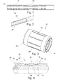
Figure 3 montre en perspective un exemple de bague à sertir pour la réalisation d'une électrode de détection/stimulation selon l'invention. - La
Figure 4 est une coupe longitudinale d'une structure d'électrode de sonde monopolaire selon l'invention, réalisée par sertissage d'une bague telle que celle de laFigure 3 sur le microcâble de laFigure 2 . - Les
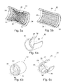
Figures 5a et 5b sont des vues arrachées de la bague d'électrode à sertir, montrant deux configurations possibles de cannelures internes. - Les
Figures 6a, 6b et 6c sont des vues arrachées schématiques montrant trois formes de réalisation possibles de reliefs formés sur la paroi interne de la bague d'électrode selon l'invention.
- The
Figure 1 illustrates in longitudinal section a typical structure of conventional monopolar probe electrode. - The
Figure 2 illustrates the structure of the isolated microcable used for the realization of the microprobe of the invention. - The
Figure 3 shows in perspective an example of crimping ring for the realization of a detection electrode / stimulation according to the invention. - The
Figure 4 is a longitudinal section of a monopolar probe electrode structure according to the invention, made by crimping a ring such as that of theFigure 3 on the microcable of theFigure 2 . - The
Figures 5a and 5b are torn out views of the crimp electrode ring, showing two possible configurations of internal splines. - The
Figures 6a, 6b and 6c are schematic torn views showing three possible embodiments of reliefs formed on the inner wall of the electrode ring according to the invention.
La
Cette construction conventionnelle comprend un corps de sonde 10 électriquement isolant, avec une lumière centrale 12 permettant l'introduction d'un fil-guide servant à l'implantation de la sonde. La région interne de la sonde comprend également un conducteur spiralé 14 (typiquement en un alliage tel que le MP35N) électriquement relié à une électrode 16 (typiquement en alliage Ptlr) rapportée sur le corps de sonde 10. Compte tenu des contraintes de dimension du fil-guide, d'épaisseur de l'isolant, etc., le diamètre d'une telle sonde conventionnelle est généralement compris entre 4 et 8 French (1,33 et 2,66 mm). De plus et surtout, la présence d'une électrode rapportée 16 introduit dans la structure de la sonde une discontinuité qui peut avoir une conséquence sur l'endurance à long terme de la sonde en cas de dimensionnement insuffisant des différents éléments.This conventional construction comprises an electrically insulating probe body with a
A la différence de ces sondes connues, l'invention concerne des microsondes dont le diamètre ne dépasse pas 2 French (0,66 mm).Unlike these known probes, the invention relates to microprobes whose diameter does not exceed 2 French (0.66 mm).
Ces microsondes sont réalisées à partir d'un microcâble gainé tel que celui illustré sur la
Le microcâble est avantageusement réalisé en un alliage du type MP35N ou MP35NLT, matériau dont l'avantage essentiel est son extrême endurance en fatigue. La structure du microcâble est avantageusement une structure multifilaire se présentant sous forme d'un toron d'une pluralité de brins conducteurs de faible diamètre ; la réduction en diamètre des brins unitaires permet en effet de réduire la contrainte appliquée à chacun d'entre eux, et donc d'augmenter les performances en fatigue de la structure du toron. Une telle structure, sans lumière interne et avec plusieurs microfils torsadés ensemble, est capable d'assurer à la fois l'endurance à l'encontre des mouvements cardiaques et la résistance aux sollicitations liées à la pose.The microcable is advantageously made of an alloy of the MP35N or MP35NLT type, a material whose essential advantage is its extreme endurance in fatigue. The structure of the microcable is advantageously a multi-wire structure in the form of a strand of a plurality of conductive strands of small diameter; the reduction in diameter of the single strands makes it possible to reduce the stress applied to each of them, and therefore to increase the fatigue performance of the strand structure. Such a structure, without internal lumen and with several microfilms twisted together, is able to provide both endurance against cardiac movements and resistance to stresses related to the pose.
La pose d'un tel microcâble dépourvu de lumière interne nécessite la mise en place préalable d'un corps de sonde implantable de façon permanente. Au préalable, le chirurgien dispose un cathéter principal lui permettant d'accéder au débouché du sinus coronaire, et un cathéter de sous-sélection permettant de choisir, sous amplificateur de brillance, le chemin du réseau veineux qui permettra d'atteindre la veine cible correspondant au site de stimulation choisi. Le chirurgien introduit ensuite dans ce cathéter un fil-guide, qu'il pousse pour le faire progresser à nu dans le réseau veineux coronaire de façon à sélectionner telle ou telle veine collatérale. Une fois la veine sélectionnée, le chirurgien enfile sur le fil-guide le corps de sonde, qu'il fait alors glisser et progresser sur le fil-guide jusqu'à l'emplacement choisi. Après retrait du fil-guide, le microcâble est enfilé dans le corps de sonde à partir de l'extrémité proximale de celui-ci, et il est poussé sur toute la longueur du corps de sonde jusqu'à émerger du débouché de l'extrémité proximale de ce dernier, puis est déployé au-delà de manière à le faire progresser, sous amplificateur de brillance, dans les veines collatérales jusqu'à atteindre la position souhaitée. Il est ainsi possible d'atteindre et de stimuler des zones du réseau coronaire veineux jusque-là inaccessibles avec des sondes conventionnelles.The installation of such a microcable without internal light requires the prior establishment of a permanently implantable probe body. Beforehand, the surgeon has a main catheter allowing him to access the outlet of the coronary sinus, and a sub-selection catheter making it possible to choose, under a brightness amplifier, the path of the venous network which will make it possible to reach the corresponding target vein. at the chosen stimulation site. The surgeon then introduces into this catheter a guide wire, which he pushes to make progress naked in the coronary venous network so as to select this or that collateral vein. Once the vein has been selected, the surgeon puts the probe body on the guidewire and slides it along the guidewire to the chosen location. After removal of the guide wire, the microcable is inserted into the probe body from the proximal end thereof, and it is pushed along the entire length of the probe body to emerge from the outlet of the proximal end thereof, and is deployed beyond to make it progress, under amplifier of brilliance, in the collateral veins until reaching the desired position. It is thus possible to reach and stimulate areas of the venous coronary network hitherto inaccessible with conventional probes.
Ces structures de microcâble sont disponibles par exemple auprès de la Société Fort Wayne Metals Inc., Fort Wayne, USA, et sont utilisées dans le domaine médical notamment pour réaliser des conducteurs de défibrillation.These microcable structures are available for example from Fort Wayne Metals Inc., Fort Wayne, USA, and are used in the medical field including to conduct defibrillation conductors.
En ce qui concerne la couche d'isolement 20, celle-ci doit répondre aux caractéristiques suivantes : résistance à la fatigue ; isolement électrique ; biocompatibilité à long terme ; biostabilité ; possibilité de transformation et mise en oeuvre compatible avec le conducteur du câble de coeur.With regard to the
Les matériaux pouvant être utilisés dans ce cadre sont notamment les matériaux du groupe comprenant : les polyuréthannes (PU), les polyesters (PET), les polyamides (PA), les polycarbonates (PC), les polyimides, les polymères fluorés, le polyéther-éther-kétone (PEEK), le poly-p-xylylène (parylène) et le polyméthacrylate de méthyle (PMM).The materials that can be used in this context include the materials of the group comprising: polyurethanes (PU), polyesters (PET), polyamides (PA), polycarbonates (PC), polyimides, fluoropolymers, polyether ether-ketone (PEEK), poly-p-xylylene (parylene) and polymethylmethacrylate (PMM).
Cependant, on privilégiera les matériaux à forte inertie chimique comme les polymères fluorés, qui présentent également une très bonne qualité d'isolation. Parmi ces composés, on peut notamment citer les matériaux du groupe comprenant : le PTFE (polytétrafluoroéthylène), le FEP (propylène perfluoré), le PFA (résine de copolymère perfluoroalkoxy), le THV (tétrafluoroéthylène, hexafluoropropylène, fluorure de vinylidène), le PVDF (polyfluorure de vinylidène), l'EFEP (éthylène propylène éthylène fluoré) et l'ETFE (éthylène tétrafluoroéthylène).However, preference will be given to materials with high chemical inertness, such as fluoropolymers, which also have a very good quality of insulation. Among these compounds, there may be mentioned materials of the group comprising: PTFE (polytetrafluoroethylene), FEP (perfluorinated propylene), PFA (perfluoroalkoxy copolymer resin), THV (tetrafluoroethylene, hexafluoropropylene, vinylidene fluoride), PVDF (polyvinylidene fluoride), EFEP (ethylene propylene fluorinated ethylene) and ETFE (ethylene tetrafluoroethylene).
Les procédés de réalisation de la couche d'isolement sur le microcâble de coeur seront fonction des matériaux utilisés, par exemple : co-extrusion sur le conducteur (pour PU, PA, PEEK, polyimides et polymères fluorés) ; dépôt par trempage dans une solution (pour PU, PA et polyimides) ; échauffement d'un tube thermorétractable (pour PET et polymères fluorés) ; dépôt chimique par voie gazeuse (pour le parylène) ; traitements plasma pour améliorer l'adhésion entre les couches.The processes for producing the insulation layer on the core microcable will depend on the materials used, for example: coextrusion on the conductor (for PU, PA, PEEK, polyimides and fluoropolymers); dip deposit in a solution (for PU, PA and polyimides); heating of a heat-shrinkable tube (for PET and fluoropolymers); chemical deposition by gas (for parylene); plasma treatments to improve adhesion between layers.
On notera par ailleurs que, bien que l'invention ait été illustrée avec une unique couche d'un même matériau gainant le microcâble 18, il est possible de prévoir plusieurs couches successives formant la gaine 20 du microcâble, par exemple une couche de PET et une couche de ETFE. Dans sa partie active, la microsonde est pourvue d'une ou plusieurs électrodes de détection/stimulation, électriquement reliées au conducteur central.Note also that, although the invention has been illustrated with a single layer of the same material sheathing the
Comme on l'a indiqué plus haut, il s'agit au niveau de ces électrodes d'obtenir la résistance à la corrosion (le matériau du microcâble étant en effet sujet au phénomène d'électrocorrosion, tout particulièrement au niveau des pièces polaires que sont les électrodes), tout en garantissant la résistance à la fatigue impérativement requise - notamment en évitant les discontinuités de structure susceptibles de créer des points de faiblesse.As indicated above, it is a matter of these electrodes to obtain the corrosion resistance (the microcable material being in fact subject to the phenomenon of electrocorrosion, especially at the level of the pole pieces which are the electrodes), while guaranteeing the required fatigue resistance - in particular by avoiding structural discontinuities that may create weak points.
La solution proposée par l'invention consiste à sertir sur le microcâble une bague telle que celle illustrée en 22 sur la
La longueur de la bague en direction longitudinale est typiquement de 0,5 à 1,5 mm pour un diamètre de l'ordre de 2 French (0,66 mm).The length of the ring in the longitudinal direction is typically 0.5 to 1.5 mm for a diameter of the order of 2 French (0.66 mm).
De façon caractéristique de l'invention, le sertissage de la bague est opéré directement sur le microcâble dans une région non dénudée de celui-ci, de sorte que ce sertissage perce très localement l'épaisseur de la gaine isolante 20 là où cette gaine est pincée entre la bague et le microcâble, établissant par ce biais un contact physique et électrique entre la face interne de la bague 22 et le matériau conducteur du microcâble 18.In a characteristic manner of the invention, the crimping of the ring is operated directly on the microcable in a non-stripped region thereof, so that this crimping very locally pierces the thickness of the insulating
La structure résultante obtenue après sertissage est illustrée en coupe
Sur la partie centrale 24 de la bague qui a subi localement le sertissage, la bague présente un diamètre réduit (sous l'effet du sertissage) par rapport aux parties d'extrémité 26 situées de part et d'autre de cette partie centrale 24. Cette géométrie résulte du sertissage différentiel de la bague, avec un effort de serrage plus élevé dans la partie centrale 24 que dans les parties d'extrémité 26. Ceci permet de créer, d'une part, le contact électrique dans la zone 28 au centre de la bague avec perçage du matériau isolant et, d'autre part, des zones de compression 30 du matériau isolant à l'entrée et à la sortie de la bague sans perçage de ce matériau, ces zones 30 assurant une étanchéité protégeant le microcâble 18 de l'électrocorrosion (lors du sertissage le matériau de la gaine est repoussé de la zone de fluage 30 vers l'extérieur en 32, à proximité des régions d'extrémité de la bague). Plus précisément :
- au droit de la partie centrale 24, la bague vient par sa face interne en contact de liaison mécanique et électrique avec les génératrices extérieures des brins à la surface du microcâble, dans la
zone 28 de ponction du matériau isolant. La résistance de contact obtenue peut être très faible, inférieure à 1 Ω, et stable ; - au droit des régions d'extrémité 26, la face interne de la bague est en contact de liaison mécanique non pas avec le microcâble, mais avec la surface de la gaine, et il y a donc dans ces régions interposition du matériau de la gaine entre le microcâble 18 et la bague 22. À cet endroit, le matériau 30 de la gaine repoussé par fluage au moment du sertissage joue le rôle de joint d'étanchéité, en formant une barrière isolante entre l'environnement extérieur et la zone de contact électrique (zone de ponction 28), et donc le matériau du microcâble, empêchant ainsi toute pénétration de fluide corporel vers la région 28 du contact électrique.
- to the right of the
central portion 24, the ring comes by its inner face in mechanical and electrical connection contact with the outer generatrices of the strands on the surface of the microcable, in thepuncture zone 28 of the insulating material. The contact resistance obtained can be very small, less than 1 Ω, and stable; - at
right end regions 26, the inner face of the ring is in mechanical contact contact not with the microcable, but with the surface of the sheath, and there is therefore in these regions interposition of the material of the sheath between the microcable 18 and thering 22. At this point, the material of the creep-sheathed sheath at the time of crimping acts as a seal, forming an insulating barrier between the external environment and the electrical contact zone. (Puncture area 28), and therefore the microcable material, thus preventing any penetration of body fluid to theregion 28 of the electrical contact.
Pour pouvoir réaliser la prise de contact par sertissage direct de la bague 22 sur le microcâble 18 revêtu de sa gaine 20, l'épaisseur de paroi de la bague est choisie relativement faible, de l'ordre de 20 à 100 µm, typiquement 25 µm, en fonction des contraintes de sertissage de manière à permettre aisément une déformation suffisante, mais sans rupture de la bague.In order to be able to make contacting by direct crimping of the
Quant à la gaine 20, son épaisseur est choisie de l'ordre de 5 à 50 µm pour pouvoir la ponctionner facilement. Par ailleurs, le matériau de cette gaine est choisi de manière à être relativement sensible au fluage, afin de se percer dès que la pression de contact (résultant de l'effort de sertissage) est suffisamment élevée. Des matériaux tels que le ETFE et le PET répondent à cette exigence, outre leurs excellentes propriétés de biocompatibilité et de tenue à la fatigue sur le long terme.As for the
Divers perfectionnements permettent d'optimiser la réalisation de la liaison de la bague au microcâble.Various improvements make it possible to optimize the production of the connection of the ring to the microcable.
Ainsi, comme illustré
Il est par ailleurs possible, comme illustré
Dans l'exemple de la
Dans ce dernier cas, chaque relief définit autour de lui une zone 44 de ponction de l'isolant, les zones de ponction 44 successives étant séparées les unes des autres par des zones intermédiaires 46 où l'isolant n'a pas été traversé. On forme ainsi des "bretelles" de matériau isolant intact reliant l'entrée et la sortie de la bague, ce qui a pour effet de procurer à la gaine isolante une meilleure endurance à la fatigue, du fait de la continuité mécanique de la gaine sur toute la longueur de la microsonde, y compris au niveau des électrodes.In the latter case, each relief defines around it a
En tout état de cause, la résistance à l'électrocorrosion de l'interface microcâble/électrode par les moyens décrits ci-dessus peut être renforcée en dotant les brins constituant le microcâble 18 d'une structure coaxiale bi-matériau, avec un coeur de brin en alliage de type MP35 associé à un revêtement d'une couche en un alliage noble, typiquement Pt-Ir, naturellement protégé contre la corrosion même dans l'hypothèse d'une infiltration accidentelle de fluide corporel.In any event, the resistance to electrocorrosion of the microcable / electrode interface by the means described above can be enhanced by providing the strands constituting the microcable 18 with a bi-material coaxial structure, with a core of strand alloy type MP35 associated with a coating of a layer of a noble alloy, typically Pt-Ir, naturally protected against corrosion even in the event of accidental infiltration of body fluid.
Enfin, pour conserver à la microsonde un caractère "isodiamètre", l'assemblage constitué par le microcâble 18 revêtu de sa gaine 20 et muni des bagues serties 22 peut être complété par une gaine thermorétractable supplémentaire 50 (
En conclusion, outre sa simplicité de conception, la solution de l'invention présente des avantages multiples :
- facilité de mise en oeuvre : on évite en effet une étape de production délicate consistant à réaliser une ablation préalable locale de l'isolant, étape qui présente des risques importants d'endommagement du microcâble ;
- protection optimale contre les risques de perfusion de fluides corporels vers le microcâble : lors du sertissage, l'isolant est repoussé à proximité immédiate des points de contact physique, renforçant alors l'étanchéité de cette zone, et évitant tout recours à un dépôt de colle silicone ou polyuréthanne, qui serait très difficile au vu des très faibles dimensions des interstices à combler (espaces résiduels entre microcâble et bague sertie) ;
- possibilité d'obtention d'un profil isodiamètre, par simple ajout d'une gaine thermorétractable ;
- maintien de la continuité mécanique structurelle du produit, du fait de la continuité du microcâble, qui n'est pas interrompu comme dans les sondes conventionnelles. Du fait de sa faible longueur, l'ajout de la bague ne modifie pas sensiblement le rayon de courbure naturelle du microcâble dû à sa propre rigidité, sous un mode de contrainte correspondant à des conditions normales d'utilisation (rayon de courbure minimal de l'ordre de 4 mm, pour une longueur de bague comprise entre 0,5 et 1,5 mm) ;
- le sertissage modifiant légèrement le profil cylindrique de la surface externe de la bague, ceci a pour effet de densifier localement le courant sortant (effet de pointe électrique), avec pour conséquence une réduction du seuil de stimulation et comme avantage corrélatif une réduction corrélative de l'énergie consommée par le système.
- ease of implementation: indeed avoids a delicate production step of performing local a prior removal of the insulation, which stage presents significant risks of damage to the microcable;
- optimal protection against the risk of perfusion of body fluids to the microcable: during crimping, the insulation is pushed back in the immediate vicinity of the physical contact points, thus reinforcing the tightness of this area, and avoiding any recourse to a glue deposit silicone or polyurethane, which would be very difficult in view of the very small dimensions of the interstices to fill (residual spaces between microcable and crimped ring);
- possibility of obtaining an isodiameter profile, by simple addition of a heat-shrinkable sheath;
- maintaining the structural structural continuity of the product, due to the continuity of the microcable, which is not interrupted as in conventional probes. Due to its short length, the addition of the ring does not substantially modify the natural radius of curvature of the microcable due to its own rigidity, under a corresponding constraint mode under normal conditions of use (minimum radius of curvature of the order of 4 mm, for a ring length of between 0.5 and 1.5 mm);
- the crimping slightly modifying the cylindrical profile of the outer surface of the ring, this has the effect of locally densifying the outgoing current (electric peak effect), with a consequent reduction of the stimulation threshold and as a correlative advantage a corresponding reduction in the energy consumed by the system.
Claims (15)
ce procédé comprenant les étapes suivantes :
le matériau isolant de la gaine restant interposé entre le microcâble et la bague dans des régions (30) situées de part et d'autre de ladite zone de ponction de la gaine.
this process comprising the following steps:
the insulating material of the remaining sheath interposed between the microcable and the ring in regions (30) located on either side of said puncture zone of the sheath.
Applications Claiming Priority (1)
| Application Number | Priority Date | Filing Date | Title |
|---|---|---|---|
| FR1254548 | 2012-05-16 |
Publications (2)
| Publication Number | Publication Date |
|---|---|
| EP2664354A1 true EP2664354A1 (en) | 2013-11-20 |
| EP2664354B1 EP2664354B1 (en) | 2015-09-16 |
Family
ID=48227100
Family Applications (1)
| Application Number | Title | Priority Date | Filing Date |
|---|---|---|---|
| EP13167517.5A Active EP2664354B1 (en) | 2012-05-16 | 2013-05-13 | Medical lead with a ring electrode for implantation in a cardiac or cerebral blood vessel and a method for its manufacture |
Country Status (2)
| Country | Link |
|---|---|
| US (3) | US9265929B2 (en) |
| EP (1) | EP2664354B1 (en) |
Cited By (4)
| Publication number | Priority date | Publication date | Assignee | Title |
|---|---|---|---|---|
| EP3459592A1 (en) | 2017-09-20 | 2019-03-27 | Sorin CRM SAS | Implantable lead |
| EP3459593A1 (en) | 2017-09-20 | 2019-03-27 | Sorin CRM SAS | Electrical connector cap for an implantable lead, implantable lead for use with said electrical connector cap, and implantable lead assembly |
| US10406350B2 (en) | 2008-11-12 | 2019-09-10 | Ecole Polytechnique Federale De Lausanne | Microfabricated neurostimulation device |
| US10441779B2 (en) | 2014-08-27 | 2019-10-15 | Aleva Neurotherapeutics | Deep brain stimulation lead |
Families Citing this family (16)
| Publication number | Priority date | Publication date | Assignee | Title |
|---|---|---|---|---|
| JP5653918B2 (en) | 2008-07-30 | 2015-01-14 | エコーレ ポリテクニーク フェデラーレ デ ローザンヌ (イーピーエフエル) | Apparatus and method for optimized stimulation of neural targets |
| JP5927176B2 (en) | 2010-04-01 | 2016-06-01 | エコーレ ポリテクニーク フェデラーレ デ ローザンヌ (イーピーエフエル) | Device for interacting with neural tissue and methods of making and using it |
| EP3476430B1 (en) | 2014-05-16 | 2020-07-01 | Aleva Neurotherapeutics SA | Device for interacting with neurological tissue |
| US11311718B2 (en) | 2014-05-16 | 2022-04-26 | Aleva Neurotherapeutics Sa | Device for interacting with neurological tissue and methods of making and using the same |
| US11338135B2 (en) | 2017-10-23 | 2022-05-24 | Cardiac Pacemakers, Inc. | Medical devices for cancer therapy with electric field shaping elements |
| US10702692B2 (en) | 2018-03-02 | 2020-07-07 | Aleva Neurotherapeutics | Neurostimulation device |
| US11426575B2 (en) * | 2018-07-06 | 2022-08-30 | Sorin Crm Sas | Connection method for connecting an isolated micro-conductor |
| EP3958959B1 (en) | 2019-04-22 | 2024-04-24 | Boston Scientific Scimed Inc. | Devices for administering electrical stimulation to treat cancer |
| US11691006B2 (en) | 2019-04-22 | 2023-07-04 | Boston Scientific Scimed, Inc. | Electrical stimulation devices for cancer treatment |
| US11607542B2 (en) | 2019-04-23 | 2023-03-21 | Boston Scientific Scimed, Inc. | Electrical stimulation for cancer treatment with internal and external electrodes |
| CN113747936A (en) | 2019-04-23 | 2021-12-03 | 波士顿科学国际有限公司 | Electrode for electrical stimulation to treat cancer |
| WO2020219521A1 (en) | 2019-04-23 | 2020-10-29 | Boston Scientific Scimed, Inc. | Electrical stimulation with thermal treatment or thermal monitoring |
| US11331502B2 (en) | 2019-04-26 | 2022-05-17 | Medtronic, Inc. | Implantable medical leads and lead extensions having an encapsulation band |
| DE102019218477B4 (en) * | 2019-11-28 | 2022-01-05 | Heraeus Deutschland GmbH & Co. KG | Micro-lead for directional stimulation |
| WO2021173509A1 (en) | 2020-02-24 | 2021-09-02 | Boston Scientific Scimed, Inc. | Systems and methods for treatment of pancreatic cancer |
| WO2024046624A1 (en) * | 2022-09-02 | 2024-03-07 | Biotronik Se & Co. Kg | Method for manufacturing an implantable lead and implantable lead |
Citations (8)
| Publication number | Priority date | Publication date | Assignee | Title |
|---|---|---|---|---|
| US5370684A (en) | 1986-12-12 | 1994-12-06 | Sorin Biomedica S.P.A. | Prosthesis of polymeric material coated with biocompatible carbon |
| US5387247A (en) | 1983-10-25 | 1995-02-07 | Sorin Biomedia S.P.A. | Prosthetic device having a biocompatible carbon film thereon and a method of and apparatus for forming such device |
| US6018684A (en) | 1998-07-30 | 2000-01-25 | Cardiac Pacemakers, Inc. | Slotted pacing/shocking electrode |
| US20050113896A1 (en) | 2003-11-20 | 2005-05-26 | Medtronic, Inc. | Novel welded junction for medical electrical leads |
| US20060229693A1 (en) * | 2005-03-31 | 2006-10-12 | Bauer Ryan T | Medical electrical lead with co-radial multi-conductor coil |
| US20060265037A1 (en) | 2001-11-13 | 2006-11-23 | Kuzma Janusz A | Construction of cylindrical multicontact electrode lead for neural stimulation and method of making same |
| US20090134134A1 (en) | 2000-09-26 | 2009-05-28 | Wessman Bradley J | Medical lead and method for medical lead manufacture |
| EP2455131A1 (en) | 2010-11-19 | 2012-05-23 | Sorin CRM SAS | Probe for stimulating a left cavity of the heart which can be implanted in the coronary network |
Family Cites Families (33)
| Publication number | Priority date | Publication date | Assignee | Title |
|---|---|---|---|---|
| US3143595A (en) * | 1960-12-29 | 1964-08-04 | Thomas & Betts Corp | Polytetrafluoroethylene insulated splice connector |
| US3249666A (en) * | 1964-09-04 | 1966-05-03 | Merit Molded Plastics Inc | Method of making flexible drive tubular casings |
| US4381014A (en) * | 1980-10-10 | 1983-04-26 | Medtronic, Inc. | Ring electrode for pacing lead and method of making same |
| EP0292596B1 (en) * | 1987-05-27 | 1992-09-30 | Siemens-Elema AB | Method of electrically connecting conductors and electrodes of an implantable electrode lead |
| US5282844A (en) * | 1990-06-15 | 1994-02-01 | Medtronic, Inc. | High impedance, low polarization, low threshold miniature steriod eluting pacing lead electrodes |
| US5288954A (en) * | 1993-01-21 | 1994-02-22 | Welch Allyn, Inc. | Binaural stethoscope |
| US5354327A (en) * | 1993-04-07 | 1994-10-11 | Medtronic, Inc. | Conductor coil with specific ratio of torque to bending stiffness |
| US6216045B1 (en) * | 1999-04-26 | 2001-04-10 | Advanced Neuromodulation Systems, Inc. | Implantable lead and method of manufacture |
| US6921295B2 (en) * | 2001-04-19 | 2005-07-26 | Medtronic, Inc. | Medical lead extension and connection system |
| US7146222B2 (en) * | 2002-04-15 | 2006-12-05 | Neurospace, Inc. | Reinforced sensing and stimulation leads and use in detection systems |
| WO2007120442A2 (en) * | 2003-07-25 | 2007-10-25 | Dexcom, Inc. | Dual electrode system for a continuous analyte sensor |
| DK1723700T3 (en) * | 2004-03-01 | 2013-04-15 | Novinium Inc | High pressure power cable connector |
| US20050228469A1 (en) * | 2004-04-12 | 2005-10-13 | Cardiac Pacemakers, Inc. | Electrode and conductor interconnect and method therefor |
| US7538274B2 (en) * | 2006-01-23 | 2009-05-26 | Novinium, Inc. | Swagable high-pressure cable connectors having improved sealing means |
| US8180425B2 (en) * | 2006-12-05 | 2012-05-15 | Tyco Healthcare Group Lp | ECG lead wire organizer and dispenser |
| EP2090359A1 (en) | 2008-02-12 | 2009-08-19 | INEOS Manufacturing Belgium NV | Polymerisation reator design |
| US8141246B2 (en) * | 2008-06-20 | 2012-03-27 | Cardiac Pacemakers, Inc. | Methods and devices for joining cables |
| US7957818B2 (en) * | 2008-06-26 | 2011-06-07 | Greatbatch Ltd. | Stimulation lead design and method of manufacture |
| US20100331644A1 (en) * | 2008-11-07 | 2010-12-30 | Dexcom, Inc. | Housing for an intravascular sensor |
| US8442658B2 (en) * | 2009-01-30 | 2013-05-14 | Pacesetter, Inc. | Crimp-through crimp connector for connecting a conductor cable and an electrode of an implantable cardiac electrotherapy lead |
| EP2429631B1 (en) * | 2009-04-30 | 2014-09-10 | Medtronic, Inc. | Termination of a shield within an implantable medical lead |
| US8788061B2 (en) * | 2009-04-30 | 2014-07-22 | Medtronic, Inc. | Termination of a shield within an implantable medical lead |
| DE102009031164B4 (en) | 2009-06-30 | 2013-11-28 | Siemens Aktiengesellschaft | Automatic layer layer positioning for MR angiography measurements |
| US9351677B2 (en) * | 2009-07-02 | 2016-05-31 | Dexcom, Inc. | Analyte sensor with increased reference capacity |
| EP3970610A3 (en) * | 2009-07-02 | 2022-05-18 | Dexcom, Inc. | Analyte sensors and methods of manufacturing same |
| US8011980B2 (en) * | 2009-09-17 | 2011-09-06 | Pacesetter, Inc. | Side-loading compact crimp termination |
| CN102686273B (en) * | 2009-12-30 | 2015-04-22 | 心脏起搏器公司 | Terminal connector assembly for a medical electrical lead |
| US8594761B2 (en) * | 2010-03-03 | 2013-11-26 | Pacesetter, Inc. | Crimp terminations for conductors in implantable medical lead and method of making same |
| EP2384784B1 (en) * | 2010-05-05 | 2012-09-26 | Sorin CRM SAS | Assembly for endocavitary stimulation/defibrillation of the left ventricle |
| FR2991882A1 (en) * | 2012-06-13 | 2013-12-20 | Sorin Crm Sas | ELECTRODE STRUCTURE FOR A MULTIPOLAR DETECTION / STIMULATION MICROSONDE INTENDED TO BE IMPLANTED INTO A CARDIAC OR CEREBRAL VESSEL |
| EP2719422B1 (en) * | 2012-10-12 | 2015-02-18 | Sorin CRM SAS | Implantable multipolar detection/stimulation microprobe |
| EP2742917A1 (en) * | 2012-12-13 | 2014-06-18 | Biotronik AG | Apparatus and method for crimping an implant |
| EP2754425A1 (en) * | 2013-01-09 | 2014-07-16 | Biotronik AG | Device and method for crimping an implant |
-
2013
- 2013-05-13 EP EP13167517.5A patent/EP2664354B1/en active Active
- 2013-05-16 US US13/895,974 patent/US9265929B2/en active Active
-
2016
- 2016-02-19 US US15/048,377 patent/US10071238B2/en active Active
-
2018
- 2018-09-07 US US16/125,657 patent/US11103694B2/en active Active
Patent Citations (8)
| Publication number | Priority date | Publication date | Assignee | Title |
|---|---|---|---|---|
| US5387247A (en) | 1983-10-25 | 1995-02-07 | Sorin Biomedia S.P.A. | Prosthetic device having a biocompatible carbon film thereon and a method of and apparatus for forming such device |
| US5370684A (en) | 1986-12-12 | 1994-12-06 | Sorin Biomedica S.P.A. | Prosthesis of polymeric material coated with biocompatible carbon |
| US6018684A (en) | 1998-07-30 | 2000-01-25 | Cardiac Pacemakers, Inc. | Slotted pacing/shocking electrode |
| US20090134134A1 (en) | 2000-09-26 | 2009-05-28 | Wessman Bradley J | Medical lead and method for medical lead manufacture |
| US20060265037A1 (en) | 2001-11-13 | 2006-11-23 | Kuzma Janusz A | Construction of cylindrical multicontact electrode lead for neural stimulation and method of making same |
| US20050113896A1 (en) | 2003-11-20 | 2005-05-26 | Medtronic, Inc. | Novel welded junction for medical electrical leads |
| US20060229693A1 (en) * | 2005-03-31 | 2006-10-12 | Bauer Ryan T | Medical electrical lead with co-radial multi-conductor coil |
| EP2455131A1 (en) | 2010-11-19 | 2012-05-23 | Sorin CRM SAS | Probe for stimulating a left cavity of the heart which can be implanted in the coronary network |
Cited By (6)
| Publication number | Priority date | Publication date | Assignee | Title |
|---|---|---|---|---|
| US10406350B2 (en) | 2008-11-12 | 2019-09-10 | Ecole Polytechnique Federale De Lausanne | Microfabricated neurostimulation device |
| US10441779B2 (en) | 2014-08-27 | 2019-10-15 | Aleva Neurotherapeutics | Deep brain stimulation lead |
| EP3459592A1 (en) | 2017-09-20 | 2019-03-27 | Sorin CRM SAS | Implantable lead |
| EP3459593A1 (en) | 2017-09-20 | 2019-03-27 | Sorin CRM SAS | Electrical connector cap for an implantable lead, implantable lead for use with said electrical connector cap, and implantable lead assembly |
| US11173314B2 (en) | 2017-09-20 | 2021-11-16 | Sorin Crm Sas | Implantable lead |
| US11219773B2 (en) | 2017-09-20 | 2022-01-11 | Sorin Crm Sas | Electrical connector cap for an implantable lead, implantable lead for use with said electrical connector cap, and implantable lead assembly |
Also Published As
| Publication number | Publication date |
|---|---|
| US20190001118A1 (en) | 2019-01-03 |
| US20160166827A1 (en) | 2016-06-16 |
| US10071238B2 (en) | 2018-09-11 |
| US20130310898A1 (en) | 2013-11-21 |
| US9265929B2 (en) | 2016-02-23 |
| US11103694B2 (en) | 2021-08-31 |
| EP2664354B1 (en) | 2015-09-16 |
Similar Documents
| Publication | Publication Date | Title |
|---|---|---|
| EP2664354B1 (en) | Medical lead with a ring electrode for implantation in a cardiac or cerebral blood vessel and a method for its manufacture | |
| EP2674190B1 (en) | Electrode structure for a multipolar stimulation/sensing microprobe for implantation in a heart or brain blood vessel | |
| EP4043065A1 (en) | Detection/stimulation microprobe implantable in venous, arterial or lymphatic systems | |
| EP2878332B1 (en) | Detection/stimulation microprobe implantable in a vessel of the venous, lymphatic or arterial network | |
| EP2455131B1 (en) | Probe for stimulating a left cavity of the heart which can be implanted in the coronary network | |
| EP2457612B1 (en) | Unit for stimulation/defibrillation of the left ventricle via the endocavity or from a vein of the coronary network | |
| US11426575B2 (en) | Connection method for connecting an isolated micro-conductor | |
| EP2719422A1 (en) | Implantable multipolar detection/stimulation microprobe | |
| EP3058983A1 (en) | Detection/stimulation microprobe, in particular for multipoint neuromodulation of the central nervous system | |
| EP2682151A1 (en) | Implantable microcatheter into venous, arterial and lymphatic system | |
| FR2786701A1 (en) | Electrical heart stimulator or defibrillator has conductor, electrode(s) and atrium branch | |
| EP2719423B1 (en) | Atraumatic detection/stimulation microprobe | |
| EP2559453B1 (en) | Lead implantable in the coronary vessels for multi-zone stimulation of a left heart chamber | |
| EP1557194B1 (en) | Single-piece defibrillation sonde | |
| FR2912921A1 (en) | NON-RECTILINE PROBE AND SYSTEM FOR DEEP ELECTRICAL NEUROSTIMULATION COMPRISING SUCH A PROBE | |
| EP1986199B1 (en) | Method of producing a class 5 insulated electric conductor | |
| EP2732848B1 (en) | Microlead for implantation in the deep coronary vessels comprising a deformable proximal part | |
| EP2810686B1 (en) | Assembly suitable for implantation in the coronary venous network for stimulation of a left heart chamber | |
| EP2813258A1 (en) | Implantable detection/stimulation microprobe including an anti-inflammatory agent | |
| FR2504383A1 (en) | CONNECTOR IMPLANTABLE IN THE BODY TO ESTABLISH A CONNECTION WITH AT LEAST ONE TERMINAL | |
| EP1036572A1 (en) | Cardiac lead implantable in the coronary veins for stimulating the left atria | |
| WO2012168378A1 (en) | Implantable bipolar cardiac stimulation probe with auxiliary stimulation pole and method of producing such a probe |
Legal Events
| Date | Code | Title | Description |
|---|---|---|---|
| PUAI | Public reference made under article 153(3) epc to a published international application that has entered the european phase |
Free format text: ORIGINAL CODE: 0009012 |
|
| AK | Designated contracting states |
Kind code of ref document: A1 Designated state(s): AL AT BE BG CH CY CZ DE DK EE ES FI FR GB GR HR HU IE IS IT LI LT LU LV MC MK MT NL NO PL PT RO RS SE SI SK SM TR |
|
| AX | Request for extension of the european patent |
Extension state: BA ME |
|
| 17P | Request for examination filed |
Effective date: 20140520 |
|
| RBV | Designated contracting states (corrected) |
Designated state(s): AL AT BE BG CH CY CZ DE DK EE ES FI FR GB GR HR HU IE IS IT LI LT LU LV MC MK MT NL NO PL PT RO RS SE SI SK SM TR |
|
| GRAP | Despatch of communication of intention to grant a patent |
Free format text: ORIGINAL CODE: EPIDOSNIGR1 |
|
| INTG | Intention to grant announced |
Effective date: 20141117 |
|
| GRAS | Grant fee paid |
Free format text: ORIGINAL CODE: EPIDOSNIGR3 |
|
| GRAA | (expected) grant |
Free format text: ORIGINAL CODE: 0009210 |
|
| AK | Designated contracting states |
Kind code of ref document: B1 Designated state(s): AL AT BE BG CH CY CZ DE DK EE ES FI FR GB GR HR HU IE IS IT LI LT LU LV MC MK MT NL NO PL PT RO RS SE SI SK SM TR |
|
| REG | Reference to a national code |
Ref country code: GB Ref legal event code: FG4D Free format text: NOT ENGLISH |
|
| REG | Reference to a national code |
Ref country code: CH Ref legal event code: EP |
|
| REG | Reference to a national code |
Ref country code: IE Ref legal event code: FG4D Free format text: LANGUAGE OF EP DOCUMENT: FRENCH |
|
| REG | Reference to a national code |
Ref country code: AT Ref legal event code: REF Ref document number: 749298 Country of ref document: AT Kind code of ref document: T Effective date: 20151015 |
|
| REG | Reference to a national code |
Ref country code: DE Ref legal event code: R096 Ref document number: 602013003016 Country of ref document: DE |
|
| REG | Reference to a national code |
Ref country code: NL Ref legal event code: MP Effective date: 20150916 |
|
| PG25 | Lapsed in a contracting state [announced via postgrant information from national office to epo] |
Ref country code: GR Free format text: LAPSE BECAUSE OF FAILURE TO SUBMIT A TRANSLATION OF THE DESCRIPTION OR TO PAY THE FEE WITHIN THE PRESCRIBED TIME-LIMIT Effective date: 20151217 Ref country code: FI Free format text: LAPSE BECAUSE OF FAILURE TO SUBMIT A TRANSLATION OF THE DESCRIPTION OR TO PAY THE FEE WITHIN THE PRESCRIBED TIME-LIMIT Effective date: 20150916 Ref country code: LT Free format text: LAPSE BECAUSE OF FAILURE TO SUBMIT A TRANSLATION OF THE DESCRIPTION OR TO PAY THE FEE WITHIN THE PRESCRIBED TIME-LIMIT Effective date: 20150916 Ref country code: LV Free format text: LAPSE BECAUSE OF FAILURE TO SUBMIT A TRANSLATION OF THE DESCRIPTION OR TO PAY THE FEE WITHIN THE PRESCRIBED TIME-LIMIT Effective date: 20150916 Ref country code: NO Free format text: LAPSE BECAUSE OF FAILURE TO SUBMIT A TRANSLATION OF THE DESCRIPTION OR TO PAY THE FEE WITHIN THE PRESCRIBED TIME-LIMIT Effective date: 20151216 |
|
| REG | Reference to a national code |
Ref country code: LT Ref legal event code: MG4D |
|
| REG | Reference to a national code |
Ref country code: AT Ref legal event code: MK05 Ref document number: 749298 Country of ref document: AT Kind code of ref document: T Effective date: 20150916 |
|
| PG25 | Lapsed in a contracting state [announced via postgrant information from national office to epo] |
Ref country code: HR Free format text: LAPSE BECAUSE OF FAILURE TO SUBMIT A TRANSLATION OF THE DESCRIPTION OR TO PAY THE FEE WITHIN THE PRESCRIBED TIME-LIMIT Effective date: 20150916 Ref country code: SE Free format text: LAPSE BECAUSE OF FAILURE TO SUBMIT A TRANSLATION OF THE DESCRIPTION OR TO PAY THE FEE WITHIN THE PRESCRIBED TIME-LIMIT Effective date: 20150916 Ref country code: RS Free format text: LAPSE BECAUSE OF FAILURE TO SUBMIT A TRANSLATION OF THE DESCRIPTION OR TO PAY THE FEE WITHIN THE PRESCRIBED TIME-LIMIT Effective date: 20150916 |
|
| PG25 | Lapsed in a contracting state [announced via postgrant information from national office to epo] |
Ref country code: NL Free format text: LAPSE BECAUSE OF FAILURE TO SUBMIT A TRANSLATION OF THE DESCRIPTION OR TO PAY THE FEE WITHIN THE PRESCRIBED TIME-LIMIT Effective date: 20150916 |
|
| REG | Reference to a national code |
Ref country code: FR Ref legal event code: PLFP Year of fee payment: 4 |
|
| PG25 | Lapsed in a contracting state [announced via postgrant information from national office to epo] |
Ref country code: CZ Free format text: LAPSE BECAUSE OF FAILURE TO SUBMIT A TRANSLATION OF THE DESCRIPTION OR TO PAY THE FEE WITHIN THE PRESCRIBED TIME-LIMIT Effective date: 20150916 Ref country code: IS Free format text: LAPSE BECAUSE OF FAILURE TO SUBMIT A TRANSLATION OF THE DESCRIPTION OR TO PAY THE FEE WITHIN THE PRESCRIBED TIME-LIMIT Effective date: 20160116 Ref country code: SK Free format text: LAPSE BECAUSE OF FAILURE TO SUBMIT A TRANSLATION OF THE DESCRIPTION OR TO PAY THE FEE WITHIN THE PRESCRIBED TIME-LIMIT Effective date: 20150916 Ref country code: ES Free format text: LAPSE BECAUSE OF FAILURE TO SUBMIT A TRANSLATION OF THE DESCRIPTION OR TO PAY THE FEE WITHIN THE PRESCRIBED TIME-LIMIT Effective date: 20150916 Ref country code: EE Free format text: LAPSE BECAUSE OF FAILURE TO SUBMIT A TRANSLATION OF THE DESCRIPTION OR TO PAY THE FEE WITHIN THE PRESCRIBED TIME-LIMIT Effective date: 20150916 |
|
| PG25 | Lapsed in a contracting state [announced via postgrant information from national office to epo] |
Ref country code: PT Free format text: LAPSE BECAUSE OF FAILURE TO SUBMIT A TRANSLATION OF THE DESCRIPTION OR TO PAY THE FEE WITHIN THE PRESCRIBED TIME-LIMIT Effective date: 20160118 Ref country code: PL Free format text: LAPSE BECAUSE OF FAILURE TO SUBMIT A TRANSLATION OF THE DESCRIPTION OR TO PAY THE FEE WITHIN THE PRESCRIBED TIME-LIMIT Effective date: 20150916 Ref country code: RO Free format text: LAPSE BECAUSE OF FAILURE TO SUBMIT A TRANSLATION OF THE DESCRIPTION OR TO PAY THE FEE WITHIN THE PRESCRIBED TIME-LIMIT Effective date: 20150916 Ref country code: AT Free format text: LAPSE BECAUSE OF FAILURE TO SUBMIT A TRANSLATION OF THE DESCRIPTION OR TO PAY THE FEE WITHIN THE PRESCRIBED TIME-LIMIT Effective date: 20150916 |
|
| REG | Reference to a national code |
Ref country code: DE Ref legal event code: R097 Ref document number: 602013003016 Country of ref document: DE |
|
| PLBE | No opposition filed within time limit |
Free format text: ORIGINAL CODE: 0009261 |
|
| STAA | Information on the status of an ep patent application or granted ep patent |
Free format text: STATUS: NO OPPOSITION FILED WITHIN TIME LIMIT |
|
| 26N | No opposition filed |
Effective date: 20160617 |
|
| PG25 | Lapsed in a contracting state [announced via postgrant information from national office to epo] |
Ref country code: DK Free format text: LAPSE BECAUSE OF FAILURE TO SUBMIT A TRANSLATION OF THE DESCRIPTION OR TO PAY THE FEE WITHIN THE PRESCRIBED TIME-LIMIT Effective date: 20150916 Ref country code: BE Free format text: LAPSE BECAUSE OF NON-PAYMENT OF DUE FEES Effective date: 20160531 |
|
| PG25 | Lapsed in a contracting state [announced via postgrant information from national office to epo] |
Ref country code: SI Free format text: LAPSE BECAUSE OF FAILURE TO SUBMIT A TRANSLATION OF THE DESCRIPTION OR TO PAY THE FEE WITHIN THE PRESCRIBED TIME-LIMIT Effective date: 20150916 |
|
| PG25 | Lapsed in a contracting state [announced via postgrant information from national office to epo] |
Ref country code: LU Free format text: LAPSE BECAUSE OF FAILURE TO SUBMIT A TRANSLATION OF THE DESCRIPTION OR TO PAY THE FEE WITHIN THE PRESCRIBED TIME-LIMIT Effective date: 20160513 |
|
| REG | Reference to a national code |
Ref country code: CH Ref legal event code: PL |
|
| PG25 | Lapsed in a contracting state [announced via postgrant information from national office to epo] |
Ref country code: CH Free format text: LAPSE BECAUSE OF NON-PAYMENT OF DUE FEES Effective date: 20160531 Ref country code: LI Free format text: LAPSE BECAUSE OF NON-PAYMENT OF DUE FEES Effective date: 20160531 |
|
| REG | Reference to a national code |
Ref country code: IE Ref legal event code: MM4A |
|
| REG | Reference to a national code |
Ref country code: FR Ref legal event code: PLFP Year of fee payment: 5 |
|
| PG25 | Lapsed in a contracting state [announced via postgrant information from national office to epo] |
Ref country code: IE Free format text: LAPSE BECAUSE OF NON-PAYMENT OF DUE FEES Effective date: 20160513 |
|
| REG | Reference to a national code |
Ref country code: FR Ref legal event code: PLFP Year of fee payment: 6 |
|
| PG25 | Lapsed in a contracting state [announced via postgrant information from national office to epo] |
Ref country code: CY Free format text: LAPSE BECAUSE OF FAILURE TO SUBMIT A TRANSLATION OF THE DESCRIPTION OR TO PAY THE FEE WITHIN THE PRESCRIBED TIME-LIMIT Effective date: 20150916 Ref country code: HU Free format text: LAPSE BECAUSE OF FAILURE TO SUBMIT A TRANSLATION OF THE DESCRIPTION OR TO PAY THE FEE WITHIN THE PRESCRIBED TIME-LIMIT; INVALID AB INITIO Effective date: 20130513 Ref country code: SM Free format text: LAPSE BECAUSE OF FAILURE TO SUBMIT A TRANSLATION OF THE DESCRIPTION OR TO PAY THE FEE WITHIN THE PRESCRIBED TIME-LIMIT Effective date: 20150916 |
|
| PG25 | Lapsed in a contracting state [announced via postgrant information from national office to epo] |
Ref country code: MK Free format text: LAPSE BECAUSE OF FAILURE TO SUBMIT A TRANSLATION OF THE DESCRIPTION OR TO PAY THE FEE WITHIN THE PRESCRIBED TIME-LIMIT Effective date: 20150916 Ref country code: TR Free format text: LAPSE BECAUSE OF FAILURE TO SUBMIT A TRANSLATION OF THE DESCRIPTION OR TO PAY THE FEE WITHIN THE PRESCRIBED TIME-LIMIT Effective date: 20150916 Ref country code: MT Free format text: LAPSE BECAUSE OF FAILURE TO SUBMIT A TRANSLATION OF THE DESCRIPTION OR TO PAY THE FEE WITHIN THE PRESCRIBED TIME-LIMIT Effective date: 20150916 Ref country code: MC Free format text: LAPSE BECAUSE OF FAILURE TO SUBMIT A TRANSLATION OF THE DESCRIPTION OR TO PAY THE FEE WITHIN THE PRESCRIBED TIME-LIMIT Effective date: 20150916 |
|
| PG25 | Lapsed in a contracting state [announced via postgrant information from national office to epo] |
Ref country code: BG Free format text: LAPSE BECAUSE OF FAILURE TO SUBMIT A TRANSLATION OF THE DESCRIPTION OR TO PAY THE FEE WITHIN THE PRESCRIBED TIME-LIMIT Effective date: 20150916 |
|
| PG25 | Lapsed in a contracting state [announced via postgrant information from national office to epo] |
Ref country code: AL Free format text: LAPSE BECAUSE OF FAILURE TO SUBMIT A TRANSLATION OF THE DESCRIPTION OR TO PAY THE FEE WITHIN THE PRESCRIBED TIME-LIMIT Effective date: 20150916 |
|
| PGFP | Annual fee paid to national office [announced via postgrant information from national office to epo] |
Ref country code: IT Payment date: 20230517 Year of fee payment: 11 Ref country code: FR Payment date: 20230523 Year of fee payment: 11 Ref country code: DE Payment date: 20230510 Year of fee payment: 11 |
|
| P01 | Opt-out of the competence of the unified patent court (upc) registered |
Effective date: 20230714 |
|
| PGFP | Annual fee paid to national office [announced via postgrant information from national office to epo] |
Ref country code: GB Payment date: 20230519 Year of fee payment: 11 |