EP2656800A1 - Surgical stapling device including a camera - Google Patents
Surgical stapling device including a camera Download PDFInfo
- Publication number
- EP2656800A1 EP2656800A1 EP13165364.4A EP13165364A EP2656800A1 EP 2656800 A1 EP2656800 A1 EP 2656800A1 EP 13165364 A EP13165364 A EP 13165364A EP 2656800 A1 EP2656800 A1 EP 2656800A1
- Authority
- EP
- European Patent Office
- Prior art keywords
- anvil
- assembly
- screw
- stapling device
- view
- Prior art date
- Legal status (The legal status is an assumption and is not a legal conclusion. Google has not performed a legal analysis and makes no representation as to the accuracy of the status listed.)
- Withdrawn
Links
Images


Classifications
-
- A—HUMAN NECESSITIES
- A61—MEDICAL OR VETERINARY SCIENCE; HYGIENE
- A61B—DIAGNOSIS; SURGERY; IDENTIFICATION
- A61B1/00—Instruments for performing medical examinations of the interior of cavities or tubes of the body by visual or photographical inspection, e.g. endoscopes; Illuminating arrangements therefor
- A61B1/04—Instruments for performing medical examinations of the interior of cavities or tubes of the body by visual or photographical inspection, e.g. endoscopes; Illuminating arrangements therefor combined with photographic or television appliances
-
- A—HUMAN NECESSITIES
- A61—MEDICAL OR VETERINARY SCIENCE; HYGIENE
- A61B—DIAGNOSIS; SURGERY; IDENTIFICATION
- A61B1/00—Instruments for performing medical examinations of the interior of cavities or tubes of the body by visual or photographical inspection, e.g. endoscopes; Illuminating arrangements therefor
- A61B1/00064—Constructional details of the endoscope body
- A61B1/00071—Insertion part of the endoscope body
- A61B1/0008—Insertion part of the endoscope body characterised by distal tip features
- A61B1/00087—Tools
-
- A—HUMAN NECESSITIES
- A61—MEDICAL OR VETERINARY SCIENCE; HYGIENE
- A61B—DIAGNOSIS; SURGERY; IDENTIFICATION
- A61B1/00—Instruments for performing medical examinations of the interior of cavities or tubes of the body by visual or photographical inspection, e.g. endoscopes; Illuminating arrangements therefor
- A61B1/00163—Optical arrangements
- A61B1/00174—Optical arrangements characterised by the viewing angles
- A61B1/00183—Optical arrangements characterised by the viewing angles for variable viewing angles
-
- A—HUMAN NECESSITIES
- A61—MEDICAL OR VETERINARY SCIENCE; HYGIENE
- A61B—DIAGNOSIS; SURGERY; IDENTIFICATION
- A61B17/00—Surgical instruments, devices or methods, e.g. tourniquets
- A61B17/11—Surgical instruments, devices or methods, e.g. tourniquets for performing anastomosis; Buttons for anastomosis
- A61B17/115—Staplers for performing anastomosis in a single operation
- A61B17/1155—Circular staplers comprising a plurality of staples
-
- A—HUMAN NECESSITIES
- A61—MEDICAL OR VETERINARY SCIENCE; HYGIENE
- A61B—DIAGNOSIS; SURGERY; IDENTIFICATION
- A61B90/00—Instruments, implements or accessories specially adapted for surgery or diagnosis and not covered by any of the groups A61B1/00 - A61B50/00, e.g. for luxation treatment or for protecting wound edges
- A61B90/30—Devices for illuminating a surgical field, the devices having an interrelation with other surgical devices or with a surgical procedure
-
- A—HUMAN NECESSITIES
- A61—MEDICAL OR VETERINARY SCIENCE; HYGIENE
- A61B—DIAGNOSIS; SURGERY; IDENTIFICATION
- A61B17/00—Surgical instruments, devices or methods, e.g. tourniquets
- A61B2017/00017—Electrical control of surgical instruments
- A61B2017/00221—Electrical control of surgical instruments with wireless transmission of data, e.g. by infrared radiation or radiowaves
-
- A—HUMAN NECESSITIES
- A61—MEDICAL OR VETERINARY SCIENCE; HYGIENE
- A61B—DIAGNOSIS; SURGERY; IDENTIFICATION
- A61B17/00—Surgical instruments, devices or methods, e.g. tourniquets
- A61B2017/00681—Aspects not otherwise provided for
- A61B2017/00734—Aspects not otherwise provided for battery operated
-
- A—HUMAN NECESSITIES
- A61—MEDICAL OR VETERINARY SCIENCE; HYGIENE
- A61B—DIAGNOSIS; SURGERY; IDENTIFICATION
- A61B17/00—Surgical instruments, devices or methods, e.g. tourniquets
- A61B17/068—Surgical staplers, e.g. containing multiple staples or clamps
- A61B17/072—Surgical staplers, e.g. containing multiple staples or clamps for applying a row of staples in a single action, e.g. the staples being applied simultaneously
- A61B2017/07214—Stapler heads
- A61B2017/07257—Stapler heads characterised by its anvil
-
- A—HUMAN NECESSITIES
- A61—MEDICAL OR VETERINARY SCIENCE; HYGIENE
- A61B—DIAGNOSIS; SURGERY; IDENTIFICATION
- A61B90/00—Instruments, implements or accessories specially adapted for surgery or diagnosis and not covered by any of the groups A61B1/00 - A61B50/00, e.g. for luxation treatment or for protecting wound edges
- A61B90/36—Image-producing devices or illumination devices not otherwise provided for
- A61B90/361—Image-producing devices, e.g. surgical cameras
- A61B2090/3616—Magnifying glass
-
- A—HUMAN NECESSITIES
- A61—MEDICAL OR VETERINARY SCIENCE; HYGIENE
- A61B—DIAGNOSIS; SURGERY; IDENTIFICATION
- A61B90/00—Instruments, implements or accessories specially adapted for surgery or diagnosis and not covered by any of the groups A61B1/00 - A61B50/00, e.g. for luxation treatment or for protecting wound edges
- A61B90/36—Image-producing devices or illumination devices not otherwise provided for
- A61B90/361—Image-producing devices, e.g. surgical cameras
Definitions
- the present disclosure relates generally to a surgical instrument including a camera. More particularly, the present disclosure relates to a surgical circular stapling device for applying surgical staples to body tissue which device includes a camera.
- Anastomosis is the surgical joining of separate hollow organ sections.
- an anastomosis procedure follows surgery in which a diseased or defective section of hollow tissue is removed and the remaining end sections are to be joined.
- the end sections may be joined by either circular, end-to-end or side-to-side organ reconstruction methods.
- these instruments typically include an elongated shaft having a handle portion, at a proximal end, to actuate the instrument and a staple holding component disposed at a distal end.
- An anvil assembly including an anvil rod with attached anvil head is mounted to the distal end of the instrument adjacent the staple holding component.
- Opposed end portions of tissue of the hollow organ(s) to be stapled are clamped between the anvil head and the staple holding component.
- the clamped tissue is stapled by driving one or more staples from the staple holding component so that the ends of the staples pass through the tissue and are deformed by the anvil head.
- An annular knife is concurrently advanced to core tissue with the hollow organ to free a tubular passage within the organ.
- surgical stapling devices for performing circular anastomosis have been used to treat internal hemorrhoids in the rectum.
- the anvil head and the staple holding component of the surgical stapling device are inserted through the anus and into the rectum with the anvil head and the staple holding component in an open or unapproximated position.
- a pursestring suture is used to pull the internal hemorrhoidal tissue towards the anvil rod.
- the anvil head and the staple holding component are approximated to clamp the hemorrhoid tissue between the anvil head and the staple holding component.
- the stapling device is fired to remove the hemorrhoidal tissue and staple the cut tissue.
- a circular surgical stapling device for performing circular anastomosis and/or treating internal hemorrhoids.
- the surgical stapling device includes a handle portion or assembly, a body portion and a head portion including an anvil assembly and a shell assembly.
- the handle portion can include a rotatable approximation knob for approximating the anvil and shell assemblies and a firing trigger for actuating a firing mechanism for ejecting staples positioned within the shell assembly.
- the anvil assembly includes a tiltable anvil that provides a reduced anvil profile to reduce trauma during removal.
- the tiltable anvil tilts automatically when the device has been fired and unapproximated.
- a camera assembly is operatively coupled to a surface of the tiltable anvil.
- the camera assembly includes a lens that is positioned on a surface of the tiltable anvil such that when the tiltable anvil is in the tilted position, the lens is directed towards the staple line, thereby facilitating viewing of the staple line prior to removal of the surgical stapling device from the surgical site.
- the camera assembly may be configured and adapted to wirelessly transmit images taken by the lens. Moreover, the camera assembly may be configured and adapted to wirelessly and/or remotely receive instruction. In addition, the camera assembly may include an internal power source. The camera assembly may also include a light source to illuminate the surgical site to facilitate capturing of images. Moreover, the camera assembly may be shaped to approximate and conform to the surface of the tiltable anvil and may also include an adhesive backing to facilitate affixing the camera assembly to the surface of the tiltable anvil.
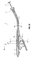
- FIG. 1 is a top side perspective view from the proximal end of the presently disclosed surgical stapling device in the unapproximated position;
- FIG. 2 is a top side perspective view from the distal end of the surgical stapling device shown in FIG. 1 ;
- FIG. 3 is a side perspective exploded view of the handle assembly of the surgical stapling device shown in FIG. 1 ;
- FIG. 3A is a top perspective view of the indicator of the handle assembly shown in FIG. 3 ;
- FIG. 4 is a side perspective view from the top of the handle assembly of the surgical stapling device shown in FIG. 1 with a handle section removed;
- FIG. 5 is a side perspective view from the bottom of the handle assembly of the surgical stapling device shown in FIG. 4 ;
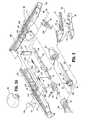
- FIG. 6 is a side perspective exploded view of the central body portion and distal head portion of the surgical stapling device shown in FIG. 1 ;
- FIG. 7 is an enlarged side perspective of the anvil retainer and band portions of the central body portion shown in FIG. 6 ;
- FIG. 8 is a side perspective view of the screw and screw stop of the approximation mechanism of the handle assembly shown in FIG. 5 ;
- FIG. 9 is an enlarged view of the indicated area of detail shown in FIG. 3 ;
- FIG. 9A is a side perspective view from the top of the abutment member of the handle assembly shown in FIG. 3 ;
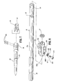
- FIG. 10 is a side perspective exploded view from the proximal end of the anvil assembly of the surgical stapling device shown in FIG. 1 ;
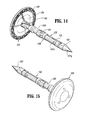
- FIG. 11 is a side perspective view of the retaining clip of the anvil assembly shown in FIG. 10 ;
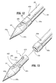
- FIG. 12 is a side perspective view of the distal end of the center rod of the anvil assembly shown in FIG. 10 with a removable trocar fastened thereto;
- FIG. 13 is a side perspective view of the center rod and removable trocar shown in FIG. 11 separated one from the other;
- FIG. 14 is a side perspective view from the proximal end of the anvil assembly shown in FIG. 10 with the removable trocar attached thereto;
- FIG. 15 is a side perspective view from the distal end of the anvil assembly shown in FIG. 14 ;
- FIG. 16 is a side cross-sectional view taken through the retaining clip of the anvil assembly and removable trocar of the anvil assembly shown in FIG. 15 ;
- FIG. 17 is an enlarged view of the indicated area of detail shown in FIG. 16 ;
- FIG. 18 is a side cross-sectional view taken through the pivot member of the anvil head assembly of the anvil assembly shown in FIG. 15 ;
- FIG. 19 is a side perspective view from the proximal end of the anvil assembly shown in FIG. 18 with the removable trocar removed;
- FIG. 20 is a perspective, partial cutaway view from the distal end of the anvil assembly shown in FIG. 19 , with the anvil head removed;
- FIG. 21 is a side cross-sectional partial cutaway view of the distal portion of the anvil assembly shown in FIG. 19 , with the anvil head in phantom;
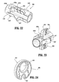
- FIG. 22 is a side perspective view from the bottom of the screw stop of the handle assembly shown in FIG. 3 ;
- FIG. 23 is a bottom perspective view from the proximal end of the screw stop shown in FIG. 22 ;
- FIG. 24 is a top perspective view of the cam adjustment member of the handle assembly shown in FIG. 3 ;
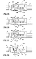
- FIG. 25 is a side view of the screw and screw stop of the handle assembly shown in FIG. 3 with the set screw and the cam adjustment member removed;
- FIG. 26 is a side view of the screw and screw stop shown in FIG. 25 with the set screw and cam adjustment member attached thereto;
- FIG. 27 is a side view of the screw and screw stop shown in FIG. 26 with the cam adjustment screw adjusted to increase the tissue gap;
- FIG. 28 is a side view of the screw and screw stop shown in FIG. 26 with the cam adjustment screw adjusted to decrease the tissue gap;
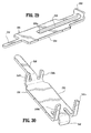
- FIG. 29 is a top perspective view from the proximal end of the slide member of the indicator mechanism of the handle assembly shown in FIG. 3 ;
- FIG. 30 is a bottom perspective view of the lockout member of the fire lockout mechanism of the handle assembly shown in FIG. 3 ;
- FIG. 31 is a side cross-sectional view of the surgical stapling device shown in FIG. 1 with the anvil assembly removed;
- FIG. 32 is a side enlarged view of the handle assembly of the surgical stapling device shown in FIG. 31 with the handle sections removed;
- FIG. 33 is an enlarged view of the indicated area of detail shown in FIG. 31 ;
- FIG. 34 is an enlarged view of the indicated area of detail shown in FIG. 31 ;
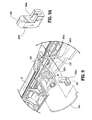
- FIG. 35 is a perspective view from the front of the distal end of the surgical stapling device shown in FIG. 31 with the anvil assembly removed;
- FIG. 36 is a perspective view from the front of the distal end of the surgical stapling device shown in FIG. 35 with an anvil assembly attached thereto;
- FIG. 37 is a side cross-sectional view of the distal end of the surgical stapling device shown in FIG. 36 ;
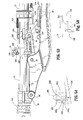
- FIG. 38 is a side cross-sectional view of the surgical stapling device shown in FIG. 31 with the anvil assembly attached thereto;
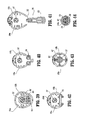
- FIG. 39 is a cross-sectional view taken along section lines 39-39 of FIG. 38 ;
- FIG. 40 is a cross-sectional view taken along section lines 40-40 of FIG. 38 ;
- FIG. 41 is a cross-sectional view taken along section lines 41-41 of FIG. 38 ;
- FIG. 42 is a cross-sectional view taken along section lines 42-42 of FIG. 38 ;
- FIG. 43 is a cross-sectional view taken along section lines 43-43 of FIG. 38 ;
- FIG. 44 is a cross-sectional view taken along section lines 44-44 of FIG. 38 ;
- FIG. 45 is a side perspective view of the surgical stapling device shown in FIG. 38 with the anvil assembly in an approximated position;
- FIG. 46 is a side cross-sectional view of the distal end of the surgical stapling device shown in FIG. 45 ;
- FIG. 47 is a side enlarged view of the handle assembly of the surgical stapling device shown in FIG. 45 with a handle section removed;
- FIG. 48 is a side cross-sectional view of the handle assembly of the surgical stapling device shown in FIG. 45 ;
- FIG. 49 is a top horizontal cross-sectional view of a portion of the handle assembly of the surgical stapling device shown in FIG. 45 ;
- FIG. 50 is a side view of a portion of the handle assembly of the surgical stapler shown in FIG. 45 with the handle sections removed;
- FIG. 51 is a side cross-sectional view of a portion of the handle assembly of the surgical stapling device shown in FIG. 45 after the firing trigger has been actuated;
- FIG. 52 is a side cross-sectional view of the distal end of the surgical stapling device shown in FIG. 45 after the firing trigger has been actuated;
- FIG. 53 is a side view of the handle assembly shown in FIG. 51 with the handle sections removed;
- FIG. 54 is an enlarged view of the firing link extension engaging the abutment member of the tactile indicator mechanism of the handle assembly shown in FIG. 53 ;
- FIG. 55 is a side cross-sectional view of the distal portion of the anvil assembly of the surgical stapling device shown in FIG. 52 ;
- FIG. 56 is a side cross-sectional view of the distal portion of the anvil assembly shown in FIG. 55 with a portion of the anvil head assembly in phantom;
- FIG. 57 is a side view of the surgical stapling device shown in FIG. 45 after the anvil assembly and cartridge assembly have been unapproximated a distance sufficient to permit the anvil head assembly to pivot on the anvil center rod;
- FIG. 58 is an enlarged view of the abutment member of the tactile indicator mechanism of the handle assembly shown in FIG. 53 (during unapproximation of the anvil and cartridge assemblies) with the wing of the screw stop, shown in phantom, in engagement with the abutment member;
- FIG. 59 is a side cross-sectional view of the anvil assembly shown in FIG. 56 as the anvil head assembly begins to tilt;
- FIG. 60 is a side cross-sectional view of the anvil assembly shown in FIG. 59 with the anvil assembly tilted;
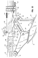
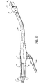
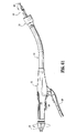
- FIG. 61 is a side view of the surgical stapling device shown in FIG. 45 with the anvil head assembly unapproximated and tilted;
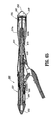
- FIG. 62 is a side cross-sectional view of another embodiment of the presently disclosed surgical stapling device with the anvil assembly removed from the anvil retainer;
- FIG. 63 is a side cross-sectional view of the surgical stapling device shown in FIG. 62 with the anvil assembly attached to the anvil retainer in the open position;
- FIG. 64 is a side cross-sectional view of the anvil assembly of the surgical stapling device shown in FIG. 63 ;
- FIG. 65 is a side cross-sectional view of the surgical stapling device shown in FIG. 63 with the anvil assembly in the approximated position;
- FIG. 66 is a side perspective view from the proximal end of the retainer extension of the surgical stapling device shown in FIG. 65 ;
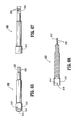
- FIG. 67 is a side view of the retainer extension shown in FIG. 66 ;
- FIG. 68 is a top cross-sectional view of the retainer extension shown in FIG. 67 ;
- FIG. 69 is a top view of the anvil retainer of the surgical stapling device shown in FIG. 65 ;
- FIG. 70 is a side view of the anvil retainer shown in FIG. 69 ;
- FIG. 71 is an enlarged view of the indicated area of detail shown in FIG. 70 ;
- FIG. 72 is a side view of the outer housing portion of the shell assembly of the surgical stapling device shown in FIG. 65 ;
- FIG. 73 is a top view of the outer housing portion of the shell assembly shown in FIG. 72 ;
- FIG. 74 is a cross-sectional view taken along section lines 74-74 of FIG. 72 ;
- FIG. 75 is a cross-sectional view taken along section lines 75-75 of FIG. 73 ;
- FIG. 76 is a side view of the inner guide portion of the shell assembly of the surgical stapling device shown in FIG. 65 ;
- FIG. 77 is a top view of the inner guide portion of the shell assembly shown in FIG. 76 ;
- FIG. 78 is a side cross-sectional view of the inner guide portion of the shell assembly shown in FIG. 77 ;
- FIG.79 is a top cross-sectional view of the inner guide portion of the shell assembly shown in FIG. 77 ;
- FIG. 80 is a side view of the pusher of the surgical stapling device shown in FIG. 65 ;
- FIG. 81 is a top view of the pusher shown in FIG. 80 ;
- FIG. 82 is a side cross-sectional view of the pusher shown in FIG. 81 ;
- FIG. 83 is a top cross-sectional view of the pusher shown in FIG. 82 ;
- FIG. 84 is a side cross-sectional view of the anvil assembly of the surgical stapling device shown in FIG. 65 ;
- FIG. 85 is a top cross-sectional view of the anvil assembly of the surgical stapling device shown in FIG. 84 ;
- FIG. 86 is a top view of the anvil center rod of the anvil assembly shown in FIG. 85 ;
- FIG. 87 is a side view of the anvil center rod of the anvil assembly shown in FIG. 85 ;
- FIG. 88 is a side cross-sectional view of the anvil head of the anvil assembly shown in FIG. 85 ;
- FIG. 89 is a side view of the anvil head shown in FIG. 88 ;
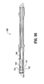
- FIG. 90 is a side cross-sectional view of the anvil center rod shown in FIG. 87 ;
- FIG. 91 is a side view of the anvil cover of the anvil assembly shown in FIG. 84 ;
- FIG. 92 is a side cross-sectional view of the anvil cover shown in FIG. 91 ;
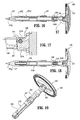
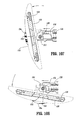
- FIG. 93 is a side cross-sectional view of an anvil assembly insertion handle
- FIG. 94 is a side perspective view of the anvil assembly insertion handle shown in FIG. 93 ;
- FIG. 95 is a side cross-sectional view of the anvil assembly insertion handle attached to the anvil assembly shown in FIG. 84 ;
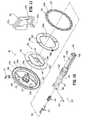
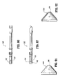
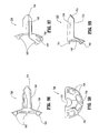
- FIG. 96 is a top view of a speculum suitable for use with the presently disclosed surgical stapling device
- FIG. 97 is a side perspective view from above of the speculum shown in FIG. 96 ;
- FIG. 98 is a rear view of the speculum shown in Fig. 96 ;
- FIG. 99 is a side cross-sectional view of the speculum shown in FIG. 97 ;
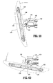
- FIG. 100 is a top side perspective view of a surgical stapling device as shown in FIG. 1 , in which the surgical stapling device includes an anvil including a camera assembly coupled thereto;
- FIG. 101 is a side view of the surgical stapling device of Fig. 100 after the anvil and cartridge assembly have been unapproximated (after firing of the staples) a distance sufficient to permit the anvil head assembly to pivot on the anvil center rod;
- FIG. 102 is a side perspective view from the distal end of the anvil assembly of the surgical stapling device shown in FIG. 100 ;
- FIG. 103 is a side cross-sectional view taken through the anvil assembly of FIG. 102 ;
- FIG. 104 is an enlarged view of the indicated area of detail shown in FIG. 103 ;
- FIG. 105 is a side cross-sectional view of the distal portion of the anvil assembly of the surgical stapling device shown in Fig. 102 ;
- FIG. 106 is a side cross-sectional view of the distal portion of the anvil assembly shown in FIG. 105 with a portion of the anvil head assembly in phantom;
- FIG. 107 is a side cross-sectional view of the anvil assembly shown in FIG. 106 as the anvil head assembly begins to tilt;
- FIG. 108 is a side cross-sectional view of the anvil assembly shown in FIG. 107 with the anvil head assembly tilted;
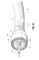
- FIG. 109 is a side view of the camera assembly of FIG. 100 shown with a removable liner partially removed.
- proximal will refer to the portion of the instrument closest to the operator and the term “distal” will refer to the portion of the instrument furthest from the operator.
- FIGS. 1 and 2 illustrate one embodiment of the presently disclosed surgical stapling device shown generally as 10.
- surgical stapling device 10 includes a proximal handle assembly 12, an elongated central body portion 14 including a curved elongated outer tube 14a, and a distal head portion 16.
- proximal handle assembly 12 an elongated central body portion 14 including a curved elongated outer tube 14a, and a distal head portion 16.
- a substantially straight central body portion may also be varied to suit a particular surgical procedure.
- Handle assembly 12 includes a stationary handle 18, a firing trigger 20, a rotatable approximation knob 22 and an indicator 24.
- Stationary handle 18 may be formed from thermoplastic handle sections 18a and 18b, e.g., polycarbonate, ( FIG. 3 ) which together define a housing for the internal components of handle assembly 12.
- Handle sections 18a and 18b may be secured together by sonic welding. Alternately, other known securement techniques may be employed including screws, adhesives, snap-fit connectors, etc.
- the internal components of handle portion 12 will be discussed in detail below.
- cushioned and/or resilient slip resistant portions such as a grip (not shown) can be fastened to or included as part of handle sections 18a and 18b and firing trigger 20.
- the slip resistant grip may be formed over handle sections 18a and 18b and firing trigger 20 using an overmolding procedure and may be formed from Neoprene polychloroprene or rubber. Alternately, other suitable, e.g., elastomeric, materials and joining techniques may be employed.
- a pivotally mounted trigger lock 26 is fastened to handle assembly 12 and is manually positioned to prevent inadvertent firing of stapling device 10.
- Indicator 24 is positioned on the stationary handle 18 and includes indicia, e.g., color coding, alphanumeric labeling, etc., to identify to a surgeon whether the device has been fired and/or when the device is ready to be fired.
- Head portion 16 includes an anvil assembly 30 and a shell assembly 31.
- the components of surgical device 10 are formed from thermoplastics including polycarbonates, and metals including stainless steel and aluminum.
- the particular material selected to form a particular component will depend upon the strength requirements of the particular component.
- the anvil may be formed from a metal, such as stainless steel
- the stationary handle may be formed from a thermoplastic such as polycarbonate.
- other materials not listed above, which can withstand sterilization procedures may be used to form components of stapling device 10 provided the materials are suitable for surgical use and meet the strength requirements of the particular component.
- FIGS. 3-5 illustrate the internal components of handle assembly 12.
- the internal components include the proximal components of approximation and firing mechanisms, a firing lockout mechanism and an indicator drive mechanism.
- FIGS. 6 and 7 illustrate the internal components of elongated body portion 14. These components include the distal components of the approximation and firing mechanisms. Each of these mechanisms will be disclosed in detail hereinbelow.
- the approximation mechanism includes approximation knob 22, a rotatable sleeve 33, a drive screw 32, first and second screw extensions 34 and 36 ( FIG. 6 ), and an anvil retainer 38.
- Rotatable sleeve 33 includes a substantially cylindrical hollow body portion 40 and a substantially cylindrical collar 42 which together define a central bore 33a.
- Collar 42 has an annular groove 44 formed thereabout and is dimensioned to receive an inwardly extending flange 46 formed on an inner wall of stationary handle 18. Engagement between groove 44 and flange 46 axially fixes sleeve 33 within handle 18 while permitting rotation of sleeve 33 in relation to stationary handle 18.
- the proximal end of body portion 40 of rotatable sleeve 33 extends through an opening 18b in the proximal end of stationary handle 18.
- a pair of diametrically opposed elongated ribs 48 are positioned on the outer surface of body portion 40.
- Approximation knob 22 includes a pair of internal slots 49a positioned to receive ribs 48 of sleeve 33 to rotatably fix sleeve 33 to knob 22, such that rotation of knob 22 causes concurrent rotation of sleeve 33.
- the proximal half of screw 32 includes a helical channel 50 and is dimensioned to be slidably positioned within central bore 33a of rotatable sleeve 33.
- the distal end of screw 32 includes an annular recess 35 dimensioned to receive a seal member 37 ( FIG. 3 ) for providing a fluid tight seal between the outer surface of screw 32 and the inner surface of pusher link 74 ( FIG. 6 ).
- a pin 52 ( FIG. 3 ) extends radially through body portion 42 of sleeve 33 into helical channel 50. Since sleeve 33 is axially fixed with respect to stationary handle 18, rotation of sleeve 33 about screw 32 causes pin 52 to move along channel 50 of screw 32 to effect axial movement of screw 32 within stationary handle 18.
- top and bottom screw extensions 34 and 36 each include a proximally located flexible flat band portion 58 and a distally located flat band portion 60.
- screw extensions 34 and 36 may have other than a band configuration.
- screw extensions 34 and 36 may be semi-circular or circular in cross-section.
- the flexibility of top and bottom screw extensions 34 and 36 permits movement of screw extensions 34 and 36 through curved elongated body portion 14.
- the proximal end of each band portion 58 includes a hole 62 dimensioned to receive a pin 64 for securing the proximal end of screw extensions 34 and 36 within transverse slot 54 of screw 32.
- each band portion 58 may be secured to screw 32, e.g., welding, crimping, etc.
- Distally located band portion 60 of each screw extension 34 and 36 is dimensioned to be received within a transverse slot 66 formed in a proximal end of anvil retainer 38 ( FIG. 7 ) to fasten anvil retainer 38 to the distal end of screw extensions 34 and 36.
- a pair of pins 66a which extend through the proximal end of anvil retainer 38 and band portions 60 are used to secure screw extensions 34 and 36 to anvil retainer 38.
- band portions 60 can be brazed or welded within slot 66 or other fastening techniques may be used to secure band portions 60 of screw extensions 34 and 36 to anvil retainer 38, e.g., screws, crimping, etc.
- Anvil retainer 38 includes an annular protrusion 177 ( FIG. 7 ) which is configured to engage the anvil assembly in a manner to be discussed in detail below.
- protrusion 177 need not be annular or may include different attachment structure, e.g., recesses, grooves, etc.
- rotatable sleeve 33 is rotated about the proximal end of screw 32 to move pin 52 along helical channel 50 of screw 32. Since sleeve 33 is axially fixed to stationary handle 18, as pin 52 is moved through channel 50, screw 32 is advanced or retracted within stationary handle 18. As a result, top and bottom screw extensions 34 and 36, which are fastened to the distal end of screw 32, and anvil retainer 38, which is fastened to the distal end of screw extensions 34 and 36, are moved axially within elongated body portion 14. Since anvil assembly 30 is secured to the distal end of anvil retainer 38, rotation of approximation knob 22 will effect movement of anvil assembly 30 in relation to shell assembly 31 between spaced and approximated positions.
- Firing trigger 20 includes a body portion 76 and a trigger cover 80.
- a cushioned gripping surface (not shown) which may be formed of Neoprene polychloroprene or rubber is provided on trigger cover 80.
- the cushioned gripping surface provides a non-slip cushioned surface to make actuation of device 10 more comfortable and less traumatic to a surgeon.
- Body portion 76 of trigger 20 is pivotally connected to a coupling member 86 (which is secured to the proximal end of pusher link 74), by a pivot member 84.
- Coupling member 86 may be formed integrally with pusher link 74 or as a separate element fastened thereto.
- Firing link 72 has a first end pivotally secured to body portion 76 of trigger 20 by a pivot member 87 and a second end pivotally secured within a vertical slot 82 formed between stationary handle half-sections 18a and 18b of stationary handle 18 by pivot member 79. Pivot member 79 is free to move vertically within slot 82.
- a spring 82a ( FIG. 9 ) is supported within handle 18 to urge pivot member 79 downwardly towards the bottom of slot 82.
- Body portion 76 further includes a pair of abutments including an abutment 89 and an abutment 91 which are positioned to engage the distal end 26a ( FIG. 4 ) of trigger lock 26 in a manner to be described in greater detail below to prevent actuation of trigger 20 prior to approximation of device 10.
- Coupling member 86 which is supported on the proximal end of elongated pusher link 74 includes a flange 104 ( FIG. 6 ).
- a spring 106 positioned between an inner wall or abutment within stationary handle 18 and flange 104, biases pusher link 74 proximally to a retracted, non-fired position.
- a pair of wings 108 extend radially outwardly from coupling member 86. Wings 108 are dimensioned to slide along channel 111 ( FIG. 3 ) formed along the internal walls of stationary handle 18 to maintain proper alignment of pusher link 74 within stationary handle 18 during firing of device 10.
- Pusher link 74 includes a pair of engagement fingers 110 which are dimensioned to lockingly engage with members 220 formed in the proximal end of pusher back 186.
- Pusher back 186 forms part of shell assembly 31 and will be discussed in greater detail below.
- Pusher link 74 may be formed from a flexible plastic material and includes a plurality of notches 187 which allow the pusher link to bend more easily as it moves through body 14.
- Pusher link 74 defines a hollow channel 75 for slidably receiving the approximation mechanism.
- a flat surface or cutout 74a formed in pusher link 74 slidably supports screw extensions 34 and 36 which are positioned in juxtaposed alignment one on top of the other.
- Spacers 77 are positioned within outer tube 14a adjacent cutout 74a to provide additional support for screw extensions 34 and 36 and pusher link 74 and prevent each component from buckling during actuation.
- An annular channel 74b is formed about pusher link 74 to receive an O-ring seal 74c.
- Pusher link 74 is slidably positioned within body portion 14 such that O-ring 74c seals the space between pusher link 74 and an internal wall of outer tube 14a. Operation of the firing mechanism of the device will be described in detail below.
- firing link 72 When firing trigger 20 is actuated, i.e., pivoted about pivot member 84, firing link 72 is moved proximally until pivot member 79 engages an abutment surface 307 ( FIG. 25, 28 and 48 ) formed on screw stop 306. Screw stop 306 is axially fixed to screw 32.
- pusher link 74 When firing trigger 20 is pushed distally, pusher link 74 is advanced distally against the bias of spring 106.
- actuation of firing trigger 20 effects advancement of pusher back 186 within shell assembly 31 to eject staples from shell assembly 31 in a manner to be described below.
- anvil assembly 30 includes an anvil head assembly 120 and an anvil center rod assembly 152.
- Anvil head assembly 120 includes a post 122, an anvil head 124, a backup plate 126, a cutting ring 128, an anvil 129 and a retaining clip 127.
- Post 122 is centrally positioned through a bore in anvil head 124.
- Anvil 129 is supported on anvil head 124 in an outer annular recess 136 and includes a plurality of pockets 140 for receiving and deforming staples.
- At least one tab 129a extends radially outwardly from anvil 129 and is dimensioned to be received within a cutout 124a formed in anvil head 124.
- Backup plate 126 includes a central opening 126b which is positioned about post 122 within an inner recess 134 of anvil head 124 between post 122 and annular recess 136.
- Backup ring 126 includes a raised platform 126a.
- Cutting ring 128 includes an opening 128a having a configuration substantially the same as platform 126a. Opening 128a is positioned about platform 126a to rotatably fix cutting ring 128a on backup ring 126.
- cutting ring 128 is formed from polyethylene and is fixedly secured to backup plate 126 using, for example, an adhesive.
- Backup ring 126 may be formed from a harder material such as a metal. Alternately other materials of construction may be used to construct plate 126 and ring 128. Cutting ring 128 and backup plate 126 are slidably mounted about post 122. Backup plate 126 includes a pair of inwardly extending tabs 150 which will be described in further detail below. Cutting ring 128 includes tabs 128b, which are received within cutouts 124b formed in anvil head 124 to properly align backup ring 126 and cutting ring 128 within anvil head 124.
- Anvil center rod assembly 152 includes anvil center rod 154, a plunger 156 and plunger spring 158.
- a first end of center rod 154 includes a transverse throughbore 160 which is offset from the central longitudinal axis of center rod 154.
- Post 122 of anvil head assembly 120 also includes a transverse throughbore 162.
- a pivot member 164 pivotably secures post 122 to center rod 154 such that anvil head assembly 120 is pivotably mounted to anvil center rod assembly 152.
- Plunger 156 is slidably positioned in a bore 154b ( FIG. 16 ) formed in the first end of center rod 154.
- Plunger 156 includes an engagement finger 168 which is offset from the pivot axis of anvil head assembly 120 and biased into engagement with the base 122a of post 122 by plunger spring 158 to urge anvil head assembly 120 to a pivoted position orthogonal to center rod 154.
- tabs 150 formed on backup plate 126 engage a top surface 154a ( FIG. 20 ) of center rod 154 to prevent anvil head assembly 120 from pivoting about pivot member 164.
- backup plate 126 and cutting ring 128 are moved deeper into anvil recess 134 of anvil head 124 about post 122 ( FIG. 21 ) by knife 188 ( FIG. 6 ) in a manner to be described in further detail below. Movement of backup plate 126 and cutting ring 128 into anvil recess 134 moves tabs 150 out of engagement with top surface 154a of center rod 154 to permit plunger 156 to pivot anvil head assembly 120 about pivot member 164.
- a retainer clip 127 is positioned in a transverse slot 122c formed in post 122 and includes a pair of outwardly biased flexible arms 127a and 127b.
- Arm 127b includes a recess 127c dimensioned to receive pivot pin 164 ( FIG. 17 ).
- arms 127a and 127b Prior to firing device 10, arms 127a and 127b are deformed inwardly by backup plate 126 ( FIG. 17 ).
- backup plate 126 FIG. 17
- flexible arms 127a and 127b spring outwardly to a position in front of backup plate 126. In this position, arms 127a and 127b prevent cutting ring 128 and backup plate 126 from sticking to knife 188 when anvil assembly 30 is unapproximated.
- a second end of center rod 154 includes a bore 170 defined by a plurality of flexible arms 155. Bore 170 is dimensioned to receive a removable trocar 157 ( FIG. 12 ).
- Flexible arms 155 each include an opening 155a dimensioned to receive a projection 157d formed on removable trocar 157 to releasably secure trocar 157 to center rod 154 ( FIG. 13 ).
- the distal ends of each of flexible arms 155 include an internal shoulder 155b dimensioned to releasably engage anvil retainer 38 ( FIG. 6 ) in a manner to be discussed in detail below.
- a plurality of splines 181 are formed about center rod 154 and are dimensioned to be received within grooves 196a ( FIG. 6 ) in shell assembly 31 to align anvil assembly 30 with shell assembly 31 during approximation of the anvil and shell assemblies.
- Center rod 154 also includes an annular recessed portion 183 to facilitate grasping of anvil assembly 30 by a surgeon with a
- Removable trocar 157 includes a trocar tip 157a, a body portion 157b and a cantilevered arm 157c.
- Projection 157d is positioned on the end of cantilevered arm 157c.
- Arm 157c is deflectable downwardly, i.e., radially inwardly, in the direction indicated by arrow "A" in FIG. 13 to facilitate insertion of body portion 157b into bore 170 of center rod 154.
- Splines 157e are provided on body portion 157b to properly align trocar 157 within bore 170 of center rod 154.
- Trocar tip 157a includes a throughbore 157g dimensioned to receive a suture (not shown) to facilitate locating and removal of trocar 157 within and from the human body. Although illustrated as having a sharpened tip, other trocar tip configurations are envisioned, e.g., blunt.
- shell assembly 31 includes a shell 182, a pusher back 186, a cylindrical knife 188, and a staple guide 192.
- Shell 182 includes an outer housing portion 194 and an inner guide portion 196 having grooves 196a for mating with splines 181 on anvil center rod 154 ( FIG. 10 ).
- Outer housing portion 194 defines a throughbore 198 having a distal cylindrical section 200, a central conical section 202 and a proximal smaller diameter cylindrical section 204.
- a plurality of openings 206 may be formed in conical section 202. Openings 206 are dimensioned to permit fluid and tissue passage during operation of the device.
- a pair of diametrically opposed flexible engagement members 207 are formed on proximal cylindrical section 204 of shell 182. Engagement members 207 are positioned to be received in openings 207a formed on the distal end of outer tube 14a to secure shell 182 to elongated body 14. A pair of openings 211 formed in the proximal end of outer tube 14a are dimensioned to receive protrusions (not shown) formed on the internal wall of stationary handle 18 ( FIG. 1 ) to facilitate attachment of tube 14a to handle portion 12.
- Pusher back 186 includes a central throughbore 208 which is slidably positioned about inner guide portion 196 of shell 182.
- Pusher back 186 includes a distal cylindrical section 210 which is slidably positioned within distal cylindrical section 200 of shell 182, a central conical section 212 and a proximal smaller diameter cylindrical section 214.
- the proximal end of pusher back 186 includes members 220 which are configured to lockingly engage with resilient fingers 110 of pusher link 74 to fasten pusher link 74 to pusher back 186 such that a distal face of pusher link 74 abuts a proximal face of pusher back 186.
- the distal end of pusher back 186 includes a pusher 190.
- Pusher 190 includes a multiplicity of distally extending fingers 226 dimensioned to be slidably received within slots 228 formed in staple guide 192 to eject staples 230 therefrom.
- Cylindrical knife 188 is frictionally retained within the central throughbore of pusher back 186 to fixedly secure knife 188 in relation to pusher 190. Alternately, knife 188 may be retained within pusher back 186 using adhesives, crimping, pins, etc.
- the distal end of knife 188 includes a circular cutting edge 234.
- pusher back 186 is advanced distally within shell 182. Advancement of pusher back 186 advances fingers 226 through slots 228 of staple guide 192 to advance staples 230 positioned within slots 228 and eject staples 230 from staple guide 192 into staple deforming pockets 140 of anvil 129 ( FIG. 11 ). Since knife 188 is secured to pusher back 186, knife 188 is also advanced distally to core tissue as will be described in more detail below.
- a rigid bushing 209 is supported in the proximal end of inner guide portion 196 of shell 182.
- Bushing 209 defines a throughbore dimensioned to slidably receive anvil retainer 38 and center rod 154 ( FIG. 10 ) of anvil assembly 30.
- Bushing 209 provides lateral support for flexible arms 155 of center rod 154 when the anvil assembly 30 has been approximated to prevent disengagement of anvil assembly 30 from anvil retainer 38. In the unapproximated position, flexible arms 155 of center rod 154 are positioned externally of bushing 209 to permit removal of anvil assembly 30 from retainer 38.
- a cam adjustment member 400 is secured by set screw 312 onto a sidewall 306a of screw stop 306 within a recess 306b formed in sidewall 306a.
- Cam adjustment member 400 includes a circular disc 402 having a throughbore 404. Throughbore 404 is eccentrically formed through disc 402 and is dimensioned to receive set screw 312. A smaller notch or hole 406 is also formed in disc 402 and is dimensioned to receive the tip of an adjustment tool (not shown).
- Recess 306b ( FIG. 22 ) includes a forward abutment shoulder or surface 306c ( FIG. 23 ) and a rear abutment surface 306d and is dimensioned to receive disc 402 such that the outer edge of disc 402 abuts forward and rear abutment surfaces 306c and 306d.
- Set screw 312 extends through disc 402 and screw stop 306 and is received in a threaded bore 32a in screw 32 to secure screw stop 306 in position on screw 32.
- Cam adjustment member 400 functions to adjust the axial position of screw stop 306 on screw 32. More specifically, set screw 312 can be loosened to allow disc 402 to rotate within recess 306b of screw stop 306 while still remaining fixed to screw 32. Since disc 402 is eccentrically mounted about screw 32 and engages forward and rear abutment surfaces 306c and 306d of recess 306b, rotation of disc 402 about fixed set screw 312 will urge screw stop 306 axially along screw 32 to adjust the axial position of screw stop 306 on screw 32.
- stapling device 10 When stapling device 10 is in a fully approximated position (as can be seen for instance in FIG. 65 ), i.e., anvil assembly 30, 640 and shell assembly 31, 605 are brought into juxtaposed alignment to define a tissue receiving clearance, screw stop 306 ( FIG. 47 ) abuts against body portion 42 of the rotatable sleeve 33, i.e., sleeve 33 functions as a stop for the approximation mechanism. In this position, anvil assembly 30 and shell assembly 31 are spaced slightly to define a tissue receiving clearance. By providing cam adjustment member 400, the tissue receiving clearance can be selectively adjusted to be within a desired range by adjusting the position of screw stop 306 on screw 32.
- cam adjustment member 400 permits adjustment of the tissue receiving clearance of ⁇ .045 inches, although greater or lesser adjustment capabilities are also envisioned. Typically, adjustments to the tissue receiving clearance will be made by the device manufacturer. Alternately, a hole or opening (not shown) may be provided in handle portion 12 ( FIG. 1 ) to provide direct access to adjustment member 400 to allow for adjustment of the tissue receiving clearance at the surgical site.
- the indicator mechanism includes indicator 24, lens cover 24a and slide member 500.
- Indicator 24 is pivotally supported about a pivot member 502 which may be formed monolithically with handle sections 18a and 18b.
- Lens cover 24a is positioned above indicator 24 and may be formed of magnification material to facilitate easy visualization of indicator 24.
- Slide member 500 ( FIG. 29 ) includes a body portion 504 having an elongated slot 506 formed therein, a distal abutment member or upturned lip portion 508, and a proximal extension 510. Slide member 500 is slidably positioned between handle sections 18a and 18b.
- Proximal extension 510 is slidably supported within stationary handle 18 by support structure 516 ( FIG. 5 ).
- a biasing member 512 e.g., a coil spring, is positioned in compression about proximal extension 510 between support structure 516 and body portion 504 of slide member 500 to urge slide member 500 distally within stationary handle 18.
- Indicator 24 includes a pair of downwardly extending projections 518 and 520 positioned about pivot member 502. Upturned lip portion 508 of slide member 500 is positioned between projections 518 and 520 and is positioned to engage projections 518 and 520 as it moves within stationary handle 18.
- biasing member 512 urges slide member 500 distally to move lip portion 508 into engagement with projection 518 to pivot indicator to a first position, which provides indication to a surgeon that the device has not been approximated and is not in a fire-ready condition.
- Screw stop 306 is fixedly attached to screw 32.
- Screw stop 306 includes a first engagement member 522 which is positioned to travel through slot 506 and engage the proximal end 506a of slot 506 during approximation of the device.
- engagement member 522 abuts proximal end 506a ( FIG. 29 ) of slot 506
- further approximation of device 10 moves slide plate 500 proximally within stationary handle 18 against the bias of spring 512 such that upturned lip 508 of slide member 500 engages projections 518 & 520 of indicator 24.
- Engagement between projections 518 & 520 and lip 508 causes indicator 24 to pivot about pivot member 502 to a second position. In the second position, indicator 24 provides indication to a surgeon that the device has been approximated and is now in a fire-ready position.
- the firing-lockout mechanism includes trigger lock 26 and lockout member 530.
- Trigger lock 26 is pivotally supported within bores 532 in handle sections 18a and 18b about pivot member 534.
- pivot member 534 extends from an upper edge of trigger lock 26 and is T-shaped and frictionally engages the inner wall of bores 532 to prevent free rotation of trigger lock 26.
- Tip 26a ( FIG. 5 ) of trigger lock 26 is positioned between abutments 89 and 91 on body portion 76 of firing trigger 20 to prevent actuation of trigger 20 when trigger lock 26 is in the locked position.
- Trigger lock 26 also includes a proximal extension 26b ( FIG. 4 ) which will be discussed in further detail below.
- Lockout member 530 ( FIG. 30 ) includes a body portion 536, a proximal extension 538, a pair of front legs 540a, a pair of rear legs 540b, and an abutment member or downturned lip portion 542. Lockout member 530 is slidably positioned between first and second stops 544 and 546 ( FIG. 5 ) formed on an internal wall of handle sections 18a and 18b. Stop 544 is positioned to engage rear legs 540b and stop 546 is positioned to engage front legs 540a. It is also envisioned that a single abutment member may be substituted for each pair of legs.
- a biasing member 548 e.g., a coil spring, is positioned between stop 544 and body 536 about proximal extension 538 to urge lockout 530 to its distal-most position with legs 540a abutting stop 546.
- extension 26b of trigger lock 26 is positioned beneath lip portion 542 of lockout member 530 to prevent pivotal movement of trigger lock 26, and thus prevent actuation of stapling device 10.
- screw stop 306 is secured to screw 32.
- a second engagement member or members 548 extend downwardly from screw stop 306. (See FIG. 22 ).
- engagement member 548 abuts front legs 540a of lockout member 530 to move lockout member 530 proximally against the bias of member 548 to a position in which lip portion 542 is spaced proximally of extension 26b of trigger lock 26.
- trigger lock 526 can be pivoted to permit firing of stapling device 10.
- a tactile indicator mechanism provided in stationary handle 18 includes an abutment member 580 which is slidably positioned in a vertical slot 582 defined within handle sections 18a and 18b.
- Abutment member 580 includes a protuberance 580a and a guide rib 580b.
- Protuberance 580a is dimensioned to be received within one of two detents 582a and 582b formed along a wall of slot 582.
- Abutment member 580 is movable from a retracted (downward) position, wherein protuberance 580a is positioned within detent 582a, to an extended (upward) position, wherein protuberance 580a is positioned within detent 582b.
- Detent 582c formed in vertical slot 582, is sized to slidably receive guide rib 580b and thereby maintain member 580 in contact with slot 582.
- abutment member 580 Prior to firing of stapling device 10, abutment member 580 is located in the retracted (downward) position ( FIG. 5 ). When device 10 is fired, an extension 590 of firing link 72 engages abutment member 580 and moves abutment member 580 from its retracted to its extended position. In the extended position, abutment member 580 extends into channel 111 of stationary handle 18.
- Screw stop 306 includes a pair of wings 584 which are slidably positioned in channel 111 of stationary handle 18. After stapling device 10 has been fired, abutment member 580 is positioned within channel 111. During unapproximation of anvil assembly 150 and cartridge assembly 31, one of the wings 584 of screw stop 306 engage abutment member 580 when the device has been unapproximated a sufficient distance to allow anvil assembly 30 to pivot to its reduced profile position (as will be discussed in mere detail below and as can be seen in FIG. 57 ).
- abutment member 580 and wing 584 of screw stop 306 provides a tactile and/or an audible indication to the surgeon that the anvil assembly 120 has tilted and stapling device 10 can be removed from a patient. If the surgical stapling device is unapproximated further, wing 584 will force abutment member 580 from the extended position back to the retracted position.
- FIGS. 31-35 illustrate surgical stapling device 10 in the unapproximated or open position prior to attachment of anvil assembly 30 to anvil retainer 38.
- biasing member 106 is engaged with coupling 86 to urge pusher link 74 to its proximal-most position in which coupling 86 abuts screw-stop 306.
- Biasing member 512 is engaged with slide member 500 of the indicator mechanism to position slide member 500 in engagement with projection 518 of indicator 24 to pivot indicator 24 in a clockwise direction, as viewed in FIG. 33 .
- Biasing member 549 is engaged with body 536 of lockout member 530 to urge lockout member 530 to its distal-most position, wherein lip portion 542 of lockout member 530 is positioned above extension 26b of trigger lock 26 to prevent movement of trigger lock 26 to the unlocked position.
- Biasing member 82a engages pivot member 79 to urge pivot member 79 to the base of vertical slot 82.
- Tactile indicator 580 is in the retracted or downward position with protrusion 580a positioned with detent 582a.
- FIGS. 36-44 illustrate surgical stapling device 10 with anvil assembly 30 attached to anvil retainer 38 and the anvil assembly 30 in the unapproximated or open position.
- anvil retainer 38 is positioned within bore 170 of center rod 154 of anvil assembly 30.
- Flexible arms 155 deflect outwardly to accommodate center rod 154.
- Center rod 154 is advanced onto anvil retainer 38 in the direction indicated by arrow "K" in FIG. 37 until internal shoulder 155b of flexible arms 155 passes over annular protrusion 177 formed on anvil retainer 38.
- resilient legs 155 releasably engage the anvil retainer.
- the position of the remaining components of stapling device are unaffected by attachment of anvil assembly 30 to anvil retainer 38 and remain as described above and shown in FIGS. 31-35 .
- FIGS. 45-50 illustrate surgical stapling device 10 during movement of anvil assembly 30 and cartridge assembly 31 to the approximated or closed position.
- anvil assembly 30 is moved to the approximated or closed position by rotating rotation knob 22 in the direction indicated by arrow "L" in FIG. 45 .
- Rotation of knob 22 causes cylindrical sleeve 33 to rotate to move pin 52 along helical channel 50 of screw 32.
- Movement of pin 52 ( FIG. 48 ) along helical channel 50 causes screw 32 to translate within sleeve 33.
- the distal end of screw 32 is connected to screw extensions 34 and 36 which are fastened at their distal ends to anvil retainer 38.
- screw stop 306 ( FIG. 47 ) is axially fixed to screw 32 by set screw 312.
- screw stop 306 is moved from a distal position within stationary handle 18 to a proximal position.
- first engagement member 522 formed on screw stop 306 abuts proximal end 506a of slot 506 of slide plate 500 and moves slide plate 500 proximally against the bias of spring 512.
- lip 508 of slide member 500 engages projections 518 & 520 of indicator 24 to pivot indicator 24 in a counter-clockwise direction as viewed in FIG. 48 .
- Screw stop 306 also includes a second engagement member 548 ( FIG. 47 ). As screw stop 306 is moved from the distal position to the proximal position during approximation of anvil assembly 30, second engagement member 548 engages distal legs 540a of lockout member 530 to move lockout member 530 proximally to a position in which lip portion 542 is spaced proximally of extension 26b of trigger lock 26. In this position, trigger lock 26 can be pivoted to an unlocked position to permit firing of stapling device 10.
- Abutment surface 307 comprises a substantially concave surface which is positioned to partially capture and act as a backstop for pivot 79 during firing of the stapling device.
- FIGS. 51-56 illustrate surgical stapling device 10 during the firing stroke of firing trigger 20.
- pivot member 79 engages abutment surface 307 on screw stop 306 and firing trigger 20 is pushed distally.
- the distal end of firing trigger 22 is connected through coupling member 86 to the proximal end of pusher link 74.
- pusher link 74 is moved distally to effect advancement of pusher back 186 within shell assembly 31.
- Fingers 190 of pusher back 186 engage and eject staples 230 from staple guide 192 ( FIG. 52 ).
- Cylindrical knife 188 is moved concurrently with pusher back 186 such that knife 188 moves into engagement with cutting ring 128 and backup plate 126.
- cutting ring 128 may be formed from polyethylene and backup plate 126 may be formed from a metal.
- knife 188 engages cutting ring 128, it cuts into cutting ring 128 and pushes backup plate 126 deeper into anvil head 124 to move tabs 150 from engagement with top surface 154a of center rod 154 ( FIG. 56 ).
- Anvil head 124 is now free to pivot about member 164 and is urged to do so by plunger 156.
- wing 584 of screw stop 306 engages tactile indicator 580 ( FIG. 58 ) at the point of unapproximation at which anvil assembly 124 is able to pivot to its tilted reduced profile position.
- tactile indicator 580 FIG. 58
- Contact between wing 584 and tactile indicator 580 provides a tactile and/or audible indication that anvil head 124 has tilted.
- wing 584 of screw stop 306 will force tactile indicator to the retracted position to allow stapling device 10 to move to the fully open position. In this position, flexible arms 155 are positioned distally of bushing 209 and anvil assembly 30 can be disengaged from anvil retainer 28.
- FIGS. 62-91 illustrate another embodiment of the presently disclosed surgical stapling device shown generally as 600.
- Stapling device 600 is configured and dimensioned to be particularly suitable for use in surgical procedures for removing internal hemorrhoids from a patient.
- surgical stapling device 600 includes a proximal handle assembly 601, a central body portion 603 and a distal head portion 605.
- the handle assembly 601 is substantially identical to handle assembly 12 of surgical stapling device 10 and will not be discussed in further detail herein.
- the approximation mechanism of surgical stapling device 600 includes an approximation knob 602, a rotatable sleeve 604, a drive screw 606, a retainer extension 608, and an anvil retainer 610.
- Approximation knob 602, rotatable sleeve 604 and drive screw 606 are substantially identical to the like named components described above with respect to surgical stapling device 10 and will not be described in further detail herein.
- retainer extension 608 includes a proximal end 612 defining a bore 614 dimensioned to receive the distal end of drive screw 606.
- a pair of transverse openings 618 extend through sidewalls of the proximal end of retainer extension 608 to facilitate attachment of retainer extension 608 to the distal end of drive screw 606 with a pin or screw 620 ( FIG. 62 ).
- other known attachment devices may be used, e.g., welding, brazing, screw threads, etc.
- the distal end of retainer extension 608 includes a flat finger 622 configured to be received within a slot 624 ( FIG. 69 ) formed in the proximal end of anvil retainer 610. Openings 626 and 626a in retainer extension 608 and anvil retainer 610 ( FIG. 70 ), respectively, are dimensioned to receive pins or screws 628 ( FIG. 62 ) to secure anvil retainer 610 to the distal end of retainer extension 608.
- other attachment configurations and techniques are contemplated.
- annular shoulder 632 defines an angle of about ninety-degrees with respect to the outer axial surface 610a of anvil retainer 610 ( FIG. 71 ). As will be discussed in further detail below, the sharp angle of shoulder 632 securely fastens an anvil assembly onto anvil retainer 610. As discussed above with respect to stapling device 10, when approximation knob 602 ( FIG. 62 ) is manually rotated, rotatable sleeve 604 is rotated about the proximal end of screw 606 to advance or retract screw 606 within handle assembly 601.
- anvil assembly 640 ( FIG. 64 ) is secured to anvil retainer 610. Accordingly, when approximation knob 602 is manually rotated, anvil assembly 640 will move axially with anvil retainer 610 in relation to a shell assembly 642 between spaced and approximated positions.
- distal head portion 605 ( FIG. 63 ) includes anvil assembly 640 and shell assembly 642.
- Shell assembly 642 includes a housing 644, a pusher 646, a cylindrical knife 645 and a staple guide 648.
- housing 644 includes an outer housing portion 644a and an inner guide portion 644b.
- Outer housing portion 644a ( FIGS. 72-75 ) defines an outwardly diverging throughbore 650 and includes a small diameter proximal end 652 and a large diameter distal end 654.
- Distal end 652 includes a pair of diametrically opposed spring tabs 656 for releasably engaging inner guide portion 644b in a manner to be discussed below.
- Throughbore 650 is dimensioned to slidably receive pusher 646 ( FIG. 62 ). Because of the configuration of throughbore 650 and pusher 646, pusher 646 is slidable in throughbore 650 only in a distal direction.
- a pair of stabilizing ribs 653 extend inwardly from an inner wall defining throughbore 650. Stabilizing ribs 653 engage ribs 654 ( FIG. 76 ) formed on sidewalls of inner guide portion 644b to secure inner guide portion 644b within outer housing portion 644a.
- Inner guide portion 644b ( FIGS. 76-79 ) includes a cylindrical proximal end 658, a cylindrical central portion 660 and an inner distal portion 662.
- Proximal end 658 includes a pair of openings 664 for engaging spring tabs (not shown) formed on handle assembly 612 for securing shell assembly 642 onto handle assembly 612.
- Ribs 654 are formed on inner distal portion 662 of inner guide portion 644b.
- a pair of annular ribs 666 is formed in spaced relation on central portion 660.
- Spring tabs 656 of outer housing portion 644a ( FIGS. 72-75 ) are positioned to snap fit into the space between ribs 666 to secure inner guide portion 644b to outer housing portion 644a.
- Inner distal portion 662 defines a cylindrical bore 668 for slidably receiving retainer extension 608 and anvil retainer 610 ( FIG. 62 ).
- Cylindrical bore 668 includes an annular array of ribs and grooves 676 for accurately circumferentially and axially aligning anvil assembly 640 and shell assembly 642 during approximation thereof.
- the proximal end of distal portion 662 extends proximally within central portion 660 to define therewith a pair of channels 670 ( FIG. 78 ).
- a proximal portion of channels 670 is dimensioned to slidably receive drive arms of a pusher link (not shown).
- the pusher link employed in this embodiment is similar to pusher link 74 discussed above with respect to stapling device 10 and will not be discussed in further detail herein.
- pusher 646 is slidably positioned within shell assembly housing 644.
- Pusher 646 includes a pair of proximal extensions 676 which extends through the distal end of channels 670 ( FIG. 78 ) formed in inner guide portion 644b.
- the distal end of pusher 646 includes a multiplicity of distally extending fingers 680 which are slidably received within slots formed in staple guide 648 ( FIG. 62 ).
- Staple guide 648 is fixedly retained in the distal end of outer housing portion 644a. Staples (not shown) are housed within the staple guide slots (not shown).
- a cylindrical knife 645 ( FIGS. 62 and 63 ) is secured or frictionally retained within a central throughbore of pusher 646.
- the distal end of knife 645 includes an annular cutting edge 682.
- the distal portion of pusher 646 defines an internal chamber 780 for receiving excised tissue.
- anvil assembly 640 includes an anvil head assembly 684 and an anvil center rod 686.
- Anvil head assembly 684 includes an anvil head 688, an anvil post 690, an anvil 692 and an anvil cover 694.
- Anvil cover 694 ( FIGS. 91 and 92 ) is substantially conical and includes a rounded distal portion 696 to facilitate smooth entry of anvil assembly 640 into a body lumen or orifice, e.g., anus.
- Anvil 692 is secured to anvil head 688 and includes a plurality of staple deforming pockets (not shown), as discussed above, for receiving and deforming staples.
- Anvil head assembly 684 is secured to the distal end of anvil center rod 686. Although anvil head assembly 684 may be pivotally secured to anvil center rod 686, as discussed above, in one embodiment, anvil head assembly 684 is fixedly secured to anvil center rod 686.
- anvil center rod 686 defines a central bore 700 which is partially defined by a plurality of flexile arms 702. Central bore 700 extends substantially along the longitudinal length of center rod 686. The distal end of each flexible arm 702 includes a radial projection 702a. Central bore 700 is dimensioned to slidably receive anvil retainer 610 ( FIG. 62 ) including distal extension 630 such that radial projections 702a snap over and engage annular shoulder 632 ( FIGS. 70 and 71 ) of anvil retainer 610 to secure anvil assembly 640 to anvil retainer 610. Radial projection 702a ( FIG.
- distal extension 630 of anvil retainer 610 extends through central bore 700 along a substantial portion of the length of anvil center rod 686. In one embodiment, distal extension 630 extends through central bore 700 substantially the entire length of anvil center rod 686.
- approximation knob 602 ( FIG. 63 ) is manually rotated to move screw 606 proximally, anvil retainer 610 and anvil assembly 640 are withdrawn into shell assembly 642 to move anvil head assembly 684 into approximation with shell assembly 642 ( FIG. 65 ).
- flexible arms 702 are drawn into cylindrical bore 668 of inner guide portion 644b, arms 702 are prevented from flexing outwardly to lock anvil assembly 640 to anvil retainer 610.
- stapling device 600 is particularly suitable for use in surgical procedures for removing internal hemorrhoids from a patient.
- anvil assembly 640 FIG. 64
- an insertion handle 720 may be used to facilitate insertion of anvil assembly 640 into the anus and rectum.
- handle 720 includes a gripping knob 722, a rigid shaft 725 extending distally from knob 722 and an attachment portion 724.
- Attachment portion 724 includes a detent 726 and a protrusion 728.
- Attachment portion 725 of shaft 724 is dimensioned to be slidably received within anvil center rod central bore 700.
- Detent 726 is positioned to be received within one of a plurality of suture holes 730 ( FIG. 87 ) formed in the distal end of anvil center rod 686 to releaseably lock handle 720 to anvil center rod 686.
- Protrusion 728 is positioned to be slidably received between and engaged by flexible arms 702 to properly align handle 720 with anvil center rod 686.
- a stop member 728a may also be provided on the attachment portion to limit the insertion depth of shaft 724 into central bore 700.
- a force sufficient to flex flexible arms 702 outwardly must be applied to handle 720 to release detent 726 from suture hole 730.
- a purse string suture is placed into each of the internal hemorrhoids. Thereafter, the purse string is cinched about the anvil center rod 686 to draw the internal hemorrhoids inwardly about the anvil center rod 686.
- the purse string suture may be placed into the internal hemorrhoids prior to insertion of the anvil assembly into the anus and rectum.
- an anoscope or speculum 750 may be provided to place the purse string into the internal hemorrhoids.
- Speculum 750 may include a semi-cylindrical body 752 having a tapered or blunt tip 754.
- Body 752 defines a channel or recess 756.
- the proximal end of body 752 has a semi-annular flange 758 including a plurality of openings 760 and a pair of protruding finger tabs 762.
- speculum 750 may be formed from a clear plastic material to enhance visualization. Further, the speculum 750 may include gradation markings (not shown) along the surface of the speculum 750 to assist the surgeon with knowledge of depth of placement of the hemorrhoids.
- blunt tip 754 of speculum 750 is inserted into the anus to a position in which first internal hemorrhoids hang into channel 756.
- a purse string suture is placed into a first portion of internal hemorrhoids.
- Speculum 750 is then rotated using finger tabs 762 and openings 760 until a second portion of internal hemorrhoids hang into channel 756.
- a purse string suture is placed into the second internal hemorrhoids. This process is repeated until a purse string suture has been placed into each of the internal hemorrhoids about the annulus of the anus.
- speculum 750 is removed from the anus and the anvil assembly 640 is inserted into the anus and rectum. Thereafter, the purse string sutures are cinched to draw the internal hemorrhoids in about the anvil center rod 686.
- Attachment structure such as openings, grooves, hooks, ridges or ribs, may be provided on anvil center rod 686 to secure the purse string suture and, thus, the internal hemorrhoids to the anvil center rod 686.
- the attachment structure may be in the form of an axially adjustable member, e.g., slidable hook, which may be adjusted to change the position of the purse string suture on anvil center rod 686 and within shell assembly 642.
- gradations can be placed on the center rod 686 to indicate depth of insertion of the center rod 686 or length of the suture or of sutured hemorrhoids.
- center rod 686 is attached to anvil retainer 610 in the manner discussed above.
- Distal extension 630 and anvil center rod 686 should be of a length to allow telescoping of extension 630 within anvil center rod 686 before visibility of the surgical site is obstructed by shell assembly 642 of device 600.
- the combined length of anvil center rod 686 and retainer extension 630 is at least 4.5 inches (114.3) or of a length to achieve the above objective.
- knob 602 can be manually rotated to approximate the anvil and shell assemblies and draw the internal hemorrhoids into an inner chamber 780 ( FIG. 62 ) defined within pusher 646 and within annular knife 682 of shell assembly 642.
- Firing trigger 790 ( FIG. 62 ) can now be actuated in the manner discussed above with respect to stapling device 10 to staple, sever and allow removal of the internal hemorrhoids.
- stapling device 600 is removed from the anus with the excised internal hemorrhoids contained within inner chamber 780 of shell assembly 642.
- instrument accessories may be used to assist in performing particular steps of the above described procedures.
- an anal dilator may be inserted into the anus prior to performing the above-described method steps to provide easier access to the surgical site.
- An obturator may be used to assist in placement of the dilator.
- an expandable introducer may be provided to reduce the trauma that results from insertion of the stapling device into the anus.
- any combination of the components discussed above including the stapling device, anvil assembly, insertion handle, speculum anal dilator, and/or an obturator may be included in a kit to perform a hemorrhoidal treatment procedure.
- the camera assembly 30a is configured and adapted to be operably coupled to the anvil head 124 of the anvil assembly 30.
- at least part of the camera assembly 30a may have a shape, e.g., a dome shape, which approximates the shape of the surface of the anvil head 124.
- the camera assembly 30a is placed at the distal surface of the anvil head 124 to provide forward viewing.
- the camera assembly 30a may be releasably or permanently affixed to the anvil head 124.
- the camera assembly 30a includes an adhesive backing 30d.
- the adhesive backing 30d may be formed from an epoxy to removably bond the camera assembly 30a to the outer surface of the anvil head 124.
- a removable liner 30b may cover the adhesive backing 30d prior to placement of the camera assembly 30a on the anvil head 124.
- the camera assembly 30a includes a camera lens 30c.
- An internal power source for the camera assembly 30a may be provided.
- the camera assembly 30a may be powered by a battery.
- the camera assembly 30a may wirelessly transmit images.
- the camera assembly 30a may include a light source 30e ( FIG. 109 ) to illuminate the surgical site.
- the camera assembly 30a may wirelessly receive instructions from the surgeon including instructions to begin transmitting images and to activate the light source.
- the anvil head 124 tilts as the pivot member 164 pivots ( FIGS. 103-108 ).
- the camera lens 30c also tilts. With the anvil head 124 in the tilted position, the camera lens 30c is directed towards the staple line facilitating viewing of the anastomosis prior to removal of the device 10 from the surgical site. Consequently, by providing the camera lens 30c on the tiltable anvil head, the staple line can be viewed to ensure proper sealing rather than requiring the separate steps of withdrawing the stapler and inserting an endoscope to check the quality of the staple line.
Abstract
A surgical stapling apparatus (10) including a handle assembly (12), an elongated shaft (14) extending distally from the handle assembly, a shell assembly (31)containing a plurality of staples arranged in an annular array, and a firing mechanism for advancing staples from the shell assembly. An anvil assembly (30) including a tiltable anvil head (120) movable from an aligned operative position to a tilted position. A camera assembly (30a) is operatively coupled to a distal surface of the tiltable anvil head such that an orientation of the camera assembly changes as the anvil head moves from the operative to the tilted position.
Description
- This application claims the benefit of and priority to
U.S. Provisional Patent Application No. 61/638,533, filed April 26, 2012 - The present disclosure relates generally to a surgical instrument including a camera. More particularly, the present disclosure relates to a surgical circular stapling device for applying surgical staples to body tissue which device includes a camera.
- Anastomosis is the surgical joining of separate hollow organ sections. Typically, an anastomosis procedure follows surgery in which a diseased or defective section of hollow tissue is removed and the remaining end sections are to be joined. Depending on the desired anastomosis procedure, the end sections may be joined by either circular, end-to-end or side-to-side organ reconstruction methods.
- In a circular anastomosis procedure, the two ends of the organ sections are joined by means of a stapling instrument, which drives a circular array of staples through the end section of each organ section and simultaneously cores any tissue interior of the driven circular array of staples to free the tubular passage. Examples of instruments for performing circular anastomosis of hollow organs are described in
U.S. Patent Nos. 7,303,106 ,6,053,390 ,5,588,579 ,5,119,983 ,5,005,749 ,4,646,745 ,4,576,167 , and4,473,077 , each of which is incorporated herein in its entirety by reference. Typically, these instruments include an elongated shaft having a handle portion, at a proximal end, to actuate the instrument and a staple holding component disposed at a distal end. An anvil assembly including an anvil rod with attached anvil head is mounted to the distal end of the instrument adjacent the staple holding component. Opposed end portions of tissue of the hollow organ(s) to be stapled are clamped between the anvil head and the staple holding component. The clamped tissue is stapled by driving one or more staples from the staple holding component so that the ends of the staples pass through the tissue and are deformed by the anvil head. An annular knife is concurrently advanced to core tissue with the hollow organ to free a tubular passage within the organ. - Besides anastomosis of hollow organs, surgical stapling devices for performing circular anastomosis have been used to treat internal hemorrhoids in the rectum. Typically, during use of a circular stapling device for hemorrhoid treatment, the anvil head and the staple holding component of the surgical stapling device are inserted through the anus and into the rectum with the anvil head and the staple holding component in an open or unapproximated position. Thereafter, a pursestring suture is used to pull the internal hemorrhoidal tissue towards the anvil rod. Next, the anvil head and the staple holding component are approximated to clamp the hemorrhoid tissue between the anvil head and the staple holding component. The stapling device is fired to remove the hemorrhoidal tissue and staple the cut tissue.
- It would be advantageous to increase visibility of the tissue during certain surgical procedures using the circular stapling device. Additionally, in certain instances, it would be advantageous to view the staple line after application of the surgical staplers. Currently, visual aids, such as endoscopes, may be inserted into the surgical site to view the anastomosis. This however requires removal of the stapler and time consuming insertion of the endoscope.
- In accordance with the present disclosure, a circular surgical stapling device for performing circular anastomosis and/or treating internal hemorrhoids is disclosed. The surgical stapling device includes a handle portion or assembly, a body portion and a head portion including an anvil assembly and a shell assembly. The handle portion can include a rotatable approximation knob for approximating the anvil and shell assemblies and a firing trigger for actuating a firing mechanism for ejecting staples positioned within the shell assembly.
- The anvil assembly includes a tiltable anvil that provides a reduced anvil profile to reduce trauma during removal. The tiltable anvil tilts automatically when the device has been fired and unapproximated. A camera assembly is operatively coupled to a surface of the tiltable anvil. The camera assembly includes a lens that is positioned on a surface of the tiltable anvil such that when the tiltable anvil is in the tilted position, the lens is directed towards the staple line, thereby facilitating viewing of the staple line prior to removal of the surgical stapling device from the surgical site.
- The camera assembly may be configured and adapted to wirelessly transmit images taken by the lens. Moreover, the camera assembly may be configured and adapted to wirelessly and/or remotely receive instruction. In addition, the camera assembly may include an internal power source. The camera assembly may also include a light source to illuminate the surgical site to facilitate capturing of images. Moreover, the camera assembly may be shaped to approximate and conform to the surface of the tiltable anvil and may also include an adhesive backing to facilitate affixing the camera assembly to the surface of the tiltable anvil. Without the camera assembly operatively coupled to the surgical stapling device, as described herein, a surgeon would otherwise have to remove the stapling device and insert another instrument, i.e., an endoscope, into the surgical site to view the staple line to ensure proper joining of the organ sections.
- These and other embodiments of the present disclosure will be described in greater detail below with reference to the appended figures.
- Various embodiment of the presently disclosed surgical stapling device are disclosed herein with reference to the drawings, wherein:
-
FIG. 1 is a top side perspective view from the proximal end of the presently disclosed surgical stapling device in the unapproximated position; -
FIG. 2 is a top side perspective view from the distal end of the surgical stapling device shown inFIG. 1 ; -
FIG. 3 is a side perspective exploded view of the handle assembly of the surgical stapling device shown inFIG. 1 ; -
FIG. 3A is a top perspective view of the indicator of the handle assembly shown inFIG. 3 ; -
FIG. 4 is a side perspective view from the top of the handle assembly of the surgical stapling device shown inFIG. 1 with a handle section removed; -
FIG. 5 is a side perspective view from the bottom of the handle assembly of the surgical stapling device shown inFIG. 4 ; -
FIG. 6 is a side perspective exploded view of the central body portion and distal head portion of the surgical stapling device shown inFIG. 1 ; -
FIG. 7 is an enlarged side perspective of the anvil retainer and band portions of the central body portion shown inFIG. 6 ; -
FIG. 8 is a side perspective view of the screw and screw stop of the approximation mechanism of the handle assembly shown inFIG. 5 ; -
FIG. 9 is an enlarged view of the indicated area of detail shown inFIG. 3 ; -
FIG. 9A is a side perspective view from the top of the abutment member of the handle assembly shown inFIG. 3 ; -
FIG. 10 is a side perspective exploded view from the proximal end of the anvil assembly of the surgical stapling device shown inFIG. 1 ; -
FIG. 11 is a side perspective view of the retaining clip of the anvil assembly shown inFIG. 10 ; -
FIG. 12 is a side perspective view of the distal end of the center rod of the anvil assembly shown inFIG. 10 with a removable trocar fastened thereto; -
FIG. 13 is a side perspective view of the center rod and removable trocar shown inFIG. 11 separated one from the other; -
FIG. 14 is a side perspective view from the proximal end of the anvil assembly shown inFIG. 10 with the removable trocar attached thereto; -
FIG. 15 is a side perspective view from the distal end of the anvil assembly shown inFIG. 14 ; -
FIG. 16 is a side cross-sectional view taken through the retaining clip of the anvil assembly and removable trocar of the anvil assembly shown inFIG. 15 ; -
FIG. 17 is an enlarged view of the indicated area of detail shown inFIG. 16 ; -
FIG. 18 is a side cross-sectional view taken through the pivot member of the anvil head assembly of the anvil assembly shown inFIG. 15 ; -
FIG. 19 is a side perspective view from the proximal end of the anvil assembly shown inFIG. 18 with the removable trocar removed; -
FIG. 20 is a perspective, partial cutaway view from the distal end of the anvil assembly shown inFIG. 19 , with the anvil head removed; -
FIG. 21 is a side cross-sectional partial cutaway view of the distal portion of the anvil assembly shown inFIG. 19 , with the anvil head in phantom; -
FIG. 22 is a side perspective view from the bottom of the screw stop of the handle assembly shown inFIG. 3 ; -
FIG. 23 is a bottom perspective view from the proximal end of the screw stop shown inFIG. 22 ; -
FIG. 24 is a top perspective view of the cam adjustment member of the handle assembly shown inFIG. 3 ; -
FIG. 25 is a side view of the screw and screw stop of the handle assembly shown inFIG. 3 with the set screw and the cam adjustment member removed; -
FIG. 26 is a side view of the screw and screw stop shown inFIG. 25 with the set screw and cam adjustment member attached thereto; -
FIG. 27 is a side view of the screw and screw stop shown inFIG. 26 with the cam adjustment screw adjusted to increase the tissue gap; -
FIG. 28 is a side view of the screw and screw stop shown inFIG. 26 with the cam adjustment screw adjusted to decrease the tissue gap; -
FIG. 29 is a top perspective view from the proximal end of the slide member of the indicator mechanism of the handle assembly shown inFIG. 3 ; -
FIG. 30 is a bottom perspective view of the lockout member of the fire lockout mechanism of the handle assembly shown inFIG. 3 ; -
FIG. 31 is a side cross-sectional view of the surgical stapling device shown inFIG. 1 with the anvil assembly removed; -
FIG. 32 is a side enlarged view of the handle assembly of the surgical stapling device shown inFIG. 31 with the handle sections removed; -
FIG. 33 is an enlarged view of the indicated area of detail shown inFIG. 31 ; -
FIG. 34 is an enlarged view of the indicated area of detail shown inFIG. 31 ; -
FIG. 35 is a perspective view from the front of the distal end of the surgical stapling device shown inFIG. 31 with the anvil assembly removed; -
FIG. 36 is a perspective view from the front of the distal end of the surgical stapling device shown inFIG. 35 with an anvil assembly attached thereto; -
FIG. 37 is a side cross-sectional view of the distal end of the surgical stapling device shown inFIG. 36 ; -
FIG. 38 is a side cross-sectional view of the surgical stapling device shown inFIG. 31 with the anvil assembly attached thereto; -
FIG. 39 is a cross-sectional view taken along section lines 39-39 ofFIG. 38 ; -
FIG. 40 is a cross-sectional view taken along section lines 40-40 ofFIG. 38 ; -
FIG. 41 is a cross-sectional view taken along section lines 41-41 ofFIG. 38 ; -
FIG. 42 is a cross-sectional view taken along section lines 42-42 ofFIG. 38 ; -
FIG. 43 is a cross-sectional view taken along section lines 43-43 ofFIG. 38 ; -
FIG. 44 is a cross-sectional view taken along section lines 44-44 ofFIG. 38 ; -
FIG. 45 is a side perspective view of the surgical stapling device shown inFIG. 38 with the anvil assembly in an approximated position; -
FIG. 46 is a side cross-sectional view of the distal end of the surgical stapling device shown inFIG. 45 ; -
FIG. 47 is a side enlarged view of the handle assembly of the surgical stapling device shown inFIG. 45 with a handle section removed; -
FIG. 48 is a side cross-sectional view of the handle assembly of the surgical stapling device shown inFIG. 45 ; -
FIG. 49 is a top horizontal cross-sectional view of a portion of the handle assembly of the surgical stapling device shown inFIG. 45 ; -
FIG. 50 is a side view of a portion of the handle assembly of the surgical stapler shown inFIG. 45 with the handle sections removed; -
FIG. 51 is a side cross-sectional view of a portion of the handle assembly of the surgical stapling device shown inFIG. 45 after the firing trigger has been actuated; -
FIG. 52 is a side cross-sectional view of the distal end of the surgical stapling device shown inFIG. 45 after the firing trigger has been actuated; -
FIG. 53 is a side view of the handle assembly shown inFIG. 51 with the handle sections removed; -
FIG. 54 is an enlarged view of the firing link extension engaging the abutment member of the tactile indicator mechanism of the handle assembly shown inFIG. 53 ; -
FIG. 55 is a side cross-sectional view of the distal portion of the anvil assembly of the surgical stapling device shown inFIG. 52 ; -
FIG. 56 is a side cross-sectional view of the distal portion of the anvil assembly shown inFIG. 55 with a portion of the anvil head assembly in phantom; -
FIG. 57 is a side view of the surgical stapling device shown inFIG. 45 after the anvil assembly and cartridge assembly have been unapproximated a distance sufficient to permit the anvil head assembly to pivot on the anvil center rod; -
FIG. 58 is an enlarged view of the abutment member of the tactile indicator mechanism of the handle assembly shown inFIG. 53 (during unapproximation of the anvil and cartridge assemblies) with the wing of the screw stop, shown in phantom, in engagement with the abutment member; -
FIG. 59 is a side cross-sectional view of the anvil assembly shown inFIG. 56 as the anvil head assembly begins to tilt; -
FIG. 60 is a side cross-sectional view of the anvil assembly shown inFIG. 59 with the anvil assembly tilted; -
FIG. 61 is a side view of the surgical stapling device shown inFIG. 45 with the anvil head assembly unapproximated and tilted; -
FIG. 62 is a side cross-sectional view of another embodiment of the presently disclosed surgical stapling device with the anvil assembly removed from the anvil retainer; -
FIG. 63 is a side cross-sectional view of the surgical stapling device shown inFIG. 62 with the anvil assembly attached to the anvil retainer in the open position; -
FIG. 64 is a side cross-sectional view of the anvil assembly of the surgical stapling device shown inFIG. 63 ; -
FIG. 65 is a side cross-sectional view of the surgical stapling device shown inFIG. 63 with the anvil assembly in the approximated position; -
FIG. 66 is a side perspective view from the proximal end of the retainer extension of the surgical stapling device shown inFIG. 65 ; -
FIG. 67 is a side view of the retainer extension shown inFIG. 66 ; -
FIG. 68 is a top cross-sectional view of the retainer extension shown inFIG. 67 ; -
FIG. 69 is a top view of the anvil retainer of the surgical stapling device shown inFIG. 65 ; -
FIG. 70 is a side view of the anvil retainer shown inFIG. 69 ; -
FIG. 71 is an enlarged view of the indicated area of detail shown inFIG. 70 ; -
FIG. 72 is a side view of the outer housing portion of the shell assembly of the surgical stapling device shown inFIG. 65 ; -
FIG. 73 is a top view of the outer housing portion of the shell assembly shown inFIG. 72 ; -
FIG. 74 is a cross-sectional view taken along section lines 74-74 ofFIG. 72 ; -
FIG. 75 is a cross-sectional view taken along section lines 75-75 ofFIG. 73 ; -
FIG. 76 is a side view of the inner guide portion of the shell assembly of the surgical stapling device shown inFIG. 65 ; -
FIG. 77 is a top view of the inner guide portion of the shell assembly shown inFIG. 76 ; -
FIG. 78 is a side cross-sectional view of the inner guide portion of the shell assembly shown inFIG. 77 ; -
FIG.79 is a top cross-sectional view of the inner guide portion of the shell assembly shown inFIG. 77 ; -
FIG. 80 is a side view of the pusher of the surgical stapling device shown inFIG. 65 ; -
FIG. 81 is a top view of the pusher shown inFIG. 80 ; -
FIG. 82 is a side cross-sectional view of the pusher shown inFIG. 81 ; -
FIG. 83 is a top cross-sectional view of the pusher shown inFIG. 82 ; -
FIG. 84 is a side cross-sectional view of the anvil assembly of the surgical stapling device shown inFIG. 65 ; -
FIG. 85 is a top cross-sectional view of the anvil assembly of the surgical stapling device shown inFIG. 84 ; -
FIG. 86 is a top view of the anvil center rod of the anvil assembly shown inFIG. 85 ; -
FIG. 87 is a side view of the anvil center rod of the anvil assembly shown inFIG. 85 ; -
FIG. 88 is a side cross-sectional view of the anvil head of the anvil assembly shown inFIG. 85 ; -
FIG. 89 is a side view of the anvil head shown inFIG. 88 ; -
FIG. 90 is a side cross-sectional view of the anvil center rod shown inFIG. 87 ; -
FIG. 91 is a side view of the anvil cover of the anvil assembly shown inFIG. 84 ; -
FIG. 92 is a side cross-sectional view of the anvil cover shown inFIG. 91 ; -
FIG. 93 is a side cross-sectional view of an anvil assembly insertion handle; -
FIG. 94 is a side perspective view of the anvil assembly insertion handle shown inFIG. 93 ; -
FIG. 95 is a side cross-sectional view of the anvil assembly insertion handle attached to the anvil assembly shown inFIG. 84 ; -
FIG. 96 is a top view of a speculum suitable for use with the presently disclosed surgical stapling device; -
FIG. 97 is a side perspective view from above of the speculum shown inFIG. 96 ; -
FIG. 98 is a rear view of the speculum shown inFig. 96 ; -
FIG. 99 is a side cross-sectional view of the speculum shown inFIG. 97 ; -
FIG. 100 is a top side perspective view of a surgical stapling device as shown inFIG. 1 , in which the surgical stapling device includes an anvil including a camera assembly coupled thereto; -
FIG. 101 is a side view of the surgical stapling device ofFig. 100 after the anvil and cartridge assembly have been unapproximated (after firing of the staples) a distance sufficient to permit the anvil head assembly to pivot on the anvil center rod; -
FIG. 102 is a side perspective view from the distal end of the anvil assembly of the surgical stapling device shown inFIG. 100 ; -
FIG. 103 is a side cross-sectional view taken through the anvil assembly ofFIG. 102 ; -
FIG. 104 is an enlarged view of the indicated area of detail shown inFIG. 103 ; -
FIG. 105 is a side cross-sectional view of the distal portion of the anvil assembly of the surgical stapling device shown inFig. 102 ; -
FIG. 106 is a side cross-sectional view of the distal portion of the anvil assembly shown inFIG. 105 with a portion of the anvil head assembly in phantom; -
FIG. 107 is a side cross-sectional view of the anvil assembly shown inFIG. 106 as the anvil head assembly begins to tilt; -
FIG. 108 is a side cross-sectional view of the anvil assembly shown inFIG. 107 with the anvil head assembly tilted; and -
FIG. 109 is a side view of the camera assembly ofFIG. 100 shown with a removable liner partially removed. - Embodiments of the presently disclosed surgical stapling device will now be described in detail with reference to the drawings in which like reference numerals designate identical or corresponding elements in each of the several views. Throughout this description, the term "proximal" will refer to the portion of the instrument closest to the operator and the term "distal" will refer to the portion of the instrument furthest from the operator.
-
FIGS. 1 and 2 illustrate one embodiment of the presently disclosed surgical stapling device shown generally as 10. Briefly,surgical stapling device 10 includes aproximal handle assembly 12, an elongatedcentral body portion 14 including a curved elongatedouter tube 14a, and adistal head portion 16. Alternately, in some surgical procedures, e.g., the treatment of hemorrhoids, it is desirable to have a substantially straight central body portion. The length, shape and/or the diameter ofbody portion 14 andhead portion 16 may also be varied to suit a particular surgical procedure. - Handle
assembly 12 includes astationary handle 18, a firingtrigger 20, arotatable approximation knob 22 and anindicator 24.Stationary handle 18 may be formed fromthermoplastic handle sections 18a and 18b, e.g., polycarbonate, (FIG. 3 ) which together define a housing for the internal components ofhandle assembly 12. Handlesections 18a and 18b may be secured together by sonic welding. Alternately, other known securement techniques may be employed including screws, adhesives, snap-fit connectors, etc. The internal components ofhandle portion 12 will be discussed in detail below. In one embodiment, cushioned and/or resilient slip resistant portions such as a grip (not shown) can be fastened to or included as part ofhandle sections 18a and 18b and firingtrigger 20. The slip resistant grip may be formed overhandle sections 18a and 18b and firingtrigger 20 using an overmolding procedure and may be formed from Neoprene polychloroprene or rubber. Alternately, other suitable, e.g., elastomeric, materials and joining techniques may be employed. A pivotally mountedtrigger lock 26 is fastened to handleassembly 12 and is manually positioned to prevent inadvertent firing of staplingdevice 10.Indicator 24 is positioned on thestationary handle 18 and includes indicia, e.g., color coding, alphanumeric labeling, etc., to identify to a surgeon whether the device has been fired and/or when the device is ready to be fired. -
Head portion 16 includes ananvil assembly 30 and ashell assembly 31. Each of these assemblies will be discussed in detail below. Except where otherwise noted, the components ofsurgical device 10 are formed from thermoplastics including polycarbonates, and metals including stainless steel and aluminum. The particular material selected to form a particular component will depend upon the strength requirements of the particular component. For example, the anvil may be formed from a metal, such as stainless steel, and the stationary handle may be formed from a thermoplastic such as polycarbonate. Alternately, other materials not listed above, which can withstand sterilization procedures, may be used to form components of staplingdevice 10 provided the materials are suitable for surgical use and meet the strength requirements of the particular component. -
FIGS. 3-5 illustrate the internal components ofhandle assembly 12. The internal components include the proximal components of approximation and firing mechanisms, a firing lockout mechanism and an indicator drive mechanism.FIGS. 6 and7 illustrate the internal components ofelongated body portion 14. These components include the distal components of the approximation and firing mechanisms. Each of these mechanisms will be disclosed in detail hereinbelow. - Referring to
FIGS. 3-8 , the approximation mechanism includesapproximation knob 22, arotatable sleeve 33, adrive screw 32, first andsecond screw extensions 34 and 36 (FIG. 6 ), and ananvil retainer 38.Rotatable sleeve 33 includes a substantially cylindricalhollow body portion 40 and a substantiallycylindrical collar 42 which together define acentral bore 33a.Collar 42 has anannular groove 44 formed thereabout and is dimensioned to receive an inwardly extendingflange 46 formed on an inner wall ofstationary handle 18. Engagement betweengroove 44 andflange 46 axially fixessleeve 33 withinhandle 18 while permitting rotation ofsleeve 33 in relation tostationary handle 18. The proximal end ofbody portion 40 ofrotatable sleeve 33 extends through an opening 18b in the proximal end ofstationary handle 18. A pair of diametrically opposedelongated ribs 48 are positioned on the outer surface ofbody portion 40.Approximation knob 22 includes a pair ofinternal slots 49a positioned to receiveribs 48 ofsleeve 33 to rotatably fixsleeve 33 toknob 22, such that rotation ofknob 22 causes concurrent rotation ofsleeve 33. - The proximal half of
screw 32 includes ahelical channel 50 and is dimensioned to be slidably positioned withincentral bore 33a ofrotatable sleeve 33. The distal end ofscrew 32 includes anannular recess 35 dimensioned to receive a seal member 37 (FIG. 3 ) for providing a fluid tight seal between the outer surface ofscrew 32 and the inner surface of pusher link 74 (FIG. 6 ). A pin 52 (FIG. 3 ) extends radially throughbody portion 42 ofsleeve 33 intohelical channel 50. Sincesleeve 33 is axially fixed with respect tostationary handle 18, rotation ofsleeve 33 aboutscrew 32causes pin 52 to move alongchannel 50 ofscrew 32 to effect axial movement ofscrew 32 withinstationary handle 18. - The distal end of
screw 32 includes atransverse slot 54. Top andbottom screw extensions 34 and 36 (FIG. 6 ) each include a proximally located flexibleflat band portion 58 and a distally locatedflat band portion 60. Alternately, it is envisioned thatscrew extensions extensions bottom screw extensions screw extensions elongated body portion 14. The proximal end of eachband portion 58 includes ahole 62 dimensioned to receive apin 64 for securing the proximal end ofscrew extensions transverse slot 54 ofscrew 32. Alternately, other fastening techniques may be used to secure eachband portion 58 to screw 32, e.g., welding, crimping, etc. Distally locatedband portion 60 of eachscrew extension transverse slot 66 formed in a proximal end of anvil retainer 38 (FIG. 7 ) to fastenanvil retainer 38 to the distal end ofscrew extensions pins 66a which extend through the proximal end ofanvil retainer 38 andband portions 60 are used to securescrew extensions anvil retainer 38. Alternately,band portions 60 can be brazed or welded withinslot 66 or other fastening techniques may be used to secureband portions 60 ofscrew extensions anvil retainer 38, e.g., screws, crimping, etc.Anvil retainer 38 includes an annular protrusion 177 (FIG. 7 ) which is configured to engage the anvil assembly in a manner to be discussed in detail below. Alternately,protrusion 177 need not be annular or may include different attachment structure, e.g., recesses, grooves, etc. - In operation, when
approximation knob 22 is manually rotated,rotatable sleeve 33 is rotated about the proximal end ofscrew 32 to movepin 52 alonghelical channel 50 ofscrew 32. Sincesleeve 33 is axially fixed tostationary handle 18, aspin 52 is moved throughchannel 50,screw 32 is advanced or retracted withinstationary handle 18. As a result, top andbottom screw extensions screw 32, andanvil retainer 38, which is fastened to the distal end ofscrew extensions elongated body portion 14. Sinceanvil assembly 30 is secured to the distal end ofanvil retainer 38, rotation ofapproximation knob 22 will effect movement ofanvil assembly 30 in relation toshell assembly 31 between spaced and approximated positions. - Referring to
FIG. 3-6 and9 , the firing mechanism includes firingtrigger 20, afiring link 72 and an elongated pusher link 74 (FIG. 6 ). Firingtrigger 20 includes abody portion 76 and atrigger cover 80. A cushioned gripping surface (not shown) which may be formed of Neoprene polychloroprene or rubber is provided ontrigger cover 80. The cushioned gripping surface provides a non-slip cushioned surface to make actuation ofdevice 10 more comfortable and less traumatic to a surgeon.Body portion 76 oftrigger 20 is pivotally connected to a coupling member 86 (which is secured to the proximal end of pusher link 74), by apivot member 84. Couplingmember 86 may be formed integrally withpusher link 74 or as a separate element fastened thereto. Firinglink 72 has a first end pivotally secured tobody portion 76 oftrigger 20 by apivot member 87 and a second end pivotally secured within avertical slot 82 formed between stationary handle half-sections 18a and 18b ofstationary handle 18 bypivot member 79.Pivot member 79 is free to move vertically withinslot 82. Aspring 82a (FIG. 9 ) is supported withinhandle 18 to urgepivot member 79 downwardly towards the bottom ofslot 82.Body portion 76 further includes a pair of abutments including anabutment 89 and anabutment 91 which are positioned to engage thedistal end 26a (FIG. 4 ) oftrigger lock 26 in a manner to be described in greater detail below to prevent actuation oftrigger 20 prior to approximation ofdevice 10. - Coupling
member 86 which is supported on the proximal end ofelongated pusher link 74 includes a flange 104 (FIG. 6 ). Aspring 106, positioned between an inner wall or abutment withinstationary handle 18 andflange 104, biases pusher link 74 proximally to a retracted, non-fired position. A pair ofwings 108 extend radially outwardly from couplingmember 86.Wings 108 are dimensioned to slide along channel 111 (FIG. 3 ) formed along the internal walls ofstationary handle 18 to maintain proper alignment ofpusher link 74 withinstationary handle 18 during firing ofdevice 10. - The distal end of
pusher link 74 includes a pair ofengagement fingers 110 which are dimensioned to lockingly engage withmembers 220 formed in the proximal end of pusher back 186. Pusher back 186 forms part ofshell assembly 31 and will be discussed in greater detail below.Pusher link 74 may be formed from a flexible plastic material and includes a plurality ofnotches 187 which allow the pusher link to bend more easily as it moves throughbody 14.Pusher link 74 defines ahollow channel 75 for slidably receiving the approximation mechanism. A flat surface orcutout 74a formed inpusher link 74 slidably supports screwextensions Spacers 77 are positioned withinouter tube 14aadjacent cutout 74a to provide additional support forscrew extensions pusher link 74 and prevent each component from buckling during actuation. An annular channel 74b is formed aboutpusher link 74 to receive an O-ring seal 74c.Pusher link 74 is slidably positioned withinbody portion 14 such that O-ring 74c seals the space betweenpusher link 74 and an internal wall ofouter tube 14a. Operation of the firing mechanism of the device will be described in detail below. - When firing
trigger 20 is actuated, i.e., pivoted aboutpivot member 84, firinglink 72 is moved proximally untilpivot member 79 engages an abutment surface 307 (FIG. 25, 28 and48 ) formed onscrew stop 306.Screw stop 306 is axially fixed to screw 32. When firingtrigger 20 is pushed distally,pusher link 74 is advanced distally against the bias ofspring 106. Turning again toFIG. 6 , since the distal end ofpusher link 74 is connected to pusher back 186, actuation of firingtrigger 20 effects advancement of pusher back 186 withinshell assembly 31 to eject staples fromshell assembly 31 in a manner to be described below. - Referring to
FIGS. 10-21 ,anvil assembly 30 includes ananvil head assembly 120 and an anvilcenter rod assembly 152.Anvil head assembly 120 includes apost 122, ananvil head 124, abackup plate 126, acutting ring 128, ananvil 129 and aretaining clip 127.Post 122 is centrally positioned through a bore inanvil head 124.Anvil 129 is supported onanvil head 124 in an outerannular recess 136 and includes a plurality ofpockets 140 for receiving and deforming staples. At least onetab 129a extends radially outwardly fromanvil 129 and is dimensioned to be received within a cutout 124a formed inanvil head 124.Tab 129a and cutout 124a function to alignanvil 129 withinannular recess 136.Backup plate 126 includes a central opening 126b which is positioned aboutpost 122 within aninner recess 134 ofanvil head 124 betweenpost 122 andannular recess 136.Backup ring 126 includes a raised platform 126a. Cuttingring 128 includes anopening 128a having a configuration substantially the same as platform 126a.Opening 128a is positioned about platform 126a to rotatablyfix cutting ring 128a onbackup ring 126. In one embodiment, cuttingring 128 is formed from polyethylene and is fixedly secured tobackup plate 126 using, for example, an adhesive.Backup ring 126 may be formed from a harder material such as a metal. Alternately other materials of construction may be used to constructplate 126 andring 128. Cuttingring 128 andbackup plate 126 are slidably mounted aboutpost 122.Backup plate 126 includes a pair of inwardly extendingtabs 150 which will be described in further detail below. Cuttingring 128 includes tabs 128b, which are received within cutouts 124b formed inanvil head 124 to properly alignbackup ring 126 and cuttingring 128 withinanvil head 124. - Anvil
center rod assembly 152 includesanvil center rod 154, aplunger 156 andplunger spring 158. A first end ofcenter rod 154 includes atransverse throughbore 160 which is offset from the central longitudinal axis ofcenter rod 154.Post 122 ofanvil head assembly 120 also includes atransverse throughbore 162. Apivot member 164 pivotably securespost 122 tocenter rod 154 such thatanvil head assembly 120 is pivotably mounted to anvilcenter rod assembly 152.Plunger 156 is slidably positioned in abore 154b (FIG. 16 ) formed in the first end ofcenter rod 154.Plunger 156 includes anengagement finger 168 which is offset from the pivot axis ofanvil head assembly 120 and biased into engagement with thebase 122a ofpost 122 byplunger spring 158 to urgeanvil head assembly 120 to a pivoted position orthogonal tocenter rod 154. In a prefired position,tabs 150 formed onbackup plate 126 engage atop surface 154a (FIG. 20 ) ofcenter rod 154 to preventanvil head assembly 120 from pivoting aboutpivot member 164. Asdevice 10 is fired,backup plate 126 and cuttingring 128 are moved deeper intoanvil recess 134 ofanvil head 124 about post 122 (FIG. 21 ) by knife 188 (FIG. 6 ) in a manner to be described in further detail below. Movement ofbackup plate 126 and cuttingring 128 intoanvil recess 134moves tabs 150 out of engagement withtop surface 154a ofcenter rod 154 to permitplunger 156 to pivotanvil head assembly 120 aboutpivot member 164. - A
retainer clip 127 is positioned in atransverse slot 122c formed inpost 122 and includes a pair of outwardly biasedflexible arms Arm 127b includes arecess 127c dimensioned to receive pivot pin 164 (FIG. 17 ). Prior to firingdevice 10,arms FIG. 17 ). Afterdevice 10 has been fired andbackup plate 126 has been pushed deeper intoanvil head 124 byknife 188,flexible arms backup plate 126. In this position,arms ring 128 andbackup plate 126 from sticking toknife 188 whenanvil assembly 30 is unapproximated. - A second end of
center rod 154 includes abore 170 defined by a plurality offlexible arms 155.Bore 170 is dimensioned to receive a removable trocar 157 (FIG. 12 ).Flexible arms 155 each include anopening 155a dimensioned to receive aprojection 157d formed onremovable trocar 157 to releasablysecure trocar 157 to center rod 154 (FIG. 13 ). The distal ends of each offlexible arms 155 include aninternal shoulder 155b dimensioned to releasably engage anvil retainer 38 (FIG. 6 ) in a manner to be discussed in detail below. A plurality of splines 181 (FIG. 10 ) are formed aboutcenter rod 154 and are dimensioned to be received withingrooves 196a (FIG. 6 ) inshell assembly 31 to alignanvil assembly 30 withshell assembly 31 during approximation of the anvil and shell assemblies.Center rod 154 also includes an annular recessedportion 183 to facilitate grasping ofanvil assembly 30 by a surgeon with a grasper. - Turning again to
FIG. 12-15 ,Removable trocar 157 includes atrocar tip 157a, abody portion 157b and acantilevered arm 157c.Projection 157d is positioned on the end ofcantilevered arm 157c.Arm 157c is deflectable downwardly, i.e., radially inwardly, in the direction indicated by arrow "A" inFIG. 13 to facilitate insertion ofbody portion 157b intobore 170 ofcenter rod 154.Splines 157e are provided onbody portion 157b to properly aligntrocar 157 withinbore 170 ofcenter rod 154.Arm 157c biases projection 157d outwardly such that whenprojection 157d passes beneath opening 155a incenter rod 154,projection 157d snaps intoopening 155a to releasably secureremovable trocar 157 tocenter rod 154. Atab 157f is positioned onarm 157c and can be depressed to facilitate removal oftrocar 157 fromcenter rod 154.Trocar tip 157a includes a throughbore 157g dimensioned to receive a suture (not shown) to facilitate locating and removal oftrocar 157 within and from the human body. Although illustrated as having a sharpened tip, other trocar tip configurations are envisioned, e.g., blunt. - Referring to
FIG. 6 ,shell assembly 31 includes ashell 182, a pusher back 186, acylindrical knife 188, and astaple guide 192.Shell 182 includes anouter housing portion 194 and aninner guide portion 196 havinggrooves 196a for mating withsplines 181 on anvil center rod 154 (FIG. 10 ).Outer housing portion 194 defines athroughbore 198 having a distalcylindrical section 200, a centralconical section 202 and a proximal smaller diametercylindrical section 204. A plurality ofopenings 206 may be formed inconical section 202.Openings 206 are dimensioned to permit fluid and tissue passage during operation of the device. A pair of diametrically opposedflexible engagement members 207 are formed on proximalcylindrical section 204 ofshell 182.Engagement members 207 are positioned to be received inopenings 207a formed on the distal end ofouter tube 14a to secureshell 182 toelongated body 14. A pair ofopenings 211 formed in the proximal end ofouter tube 14a are dimensioned to receive protrusions (not shown) formed on the internal wall of stationary handle 18 (FIG. 1 ) to facilitate attachment oftube 14a to handleportion 12. - Turning again to
FIG. 6 Pusher back 186 includes acentral throughbore 208 which is slidably positioned aboutinner guide portion 196 ofshell 182. Pusher back 186 includes a distalcylindrical section 210 which is slidably positioned within distalcylindrical section 200 ofshell 182, a central conical section 212 and a proximal smaller diametercylindrical section 214. The proximal end of pusher back 186 includesmembers 220 which are configured to lockingly engage withresilient fingers 110 ofpusher link 74 to fastenpusher link 74 to pusher back 186 such that a distal face ofpusher link 74 abuts a proximal face of pusher back 186. - The distal end of pusher back 186 includes a
pusher 190.Pusher 190 includes a multiplicity of distally extendingfingers 226 dimensioned to be slidably received withinslots 228 formed instaple guide 192 to ejectstaples 230 therefrom.Cylindrical knife 188 is frictionally retained within the central throughbore of pusher back 186 to fixedlysecure knife 188 in relation topusher 190. Alternately,knife 188 may be retained within pusher back 186 using adhesives, crimping, pins, etc. The distal end ofknife 188 includes acircular cutting edge 234. - In operation, when pusher link 74 is advanced distally in response to actuation of firing
trigger 20, as will be described below, pusher back 186 is advanced distally withinshell 182. Advancement of pusher back 186advances fingers 226 throughslots 228 ofstaple guide 192 to advancestaples 230 positioned withinslots 228 and ejectstaples 230 fromstaple guide 192 intostaple deforming pockets 140 of anvil 129 (FIG. 11 ). Sinceknife 188 is secured to pusher back 186,knife 188 is also advanced distally to core tissue as will be described in more detail below. - A
rigid bushing 209 is supported in the proximal end ofinner guide portion 196 ofshell 182.Bushing 209 defines a throughbore dimensioned to slidably receiveanvil retainer 38 and center rod 154 (FIG. 10 ) ofanvil assembly 30.Bushing 209 provides lateral support forflexible arms 155 ofcenter rod 154 when theanvil assembly 30 has been approximated to prevent disengagement ofanvil assembly 30 fromanvil retainer 38. In the unapproximated position,flexible arms 155 ofcenter rod 154 are positioned externally ofbushing 209 to permit removal ofanvil assembly 30 fromretainer 38. - Referring to
FIGS. 8 and22-28 , acam adjustment member 400 is secured byset screw 312 onto asidewall 306a of screw stop 306 within arecess 306b formed insidewall 306a.Cam adjustment member 400 includes acircular disc 402 having athroughbore 404.Throughbore 404 is eccentrically formed throughdisc 402 and is dimensioned to receive setscrew 312. A smaller notch orhole 406 is also formed indisc 402 and is dimensioned to receive the tip of an adjustment tool (not shown).Recess 306b (FIG. 22 ) includes a forward abutment shoulder orsurface 306c (FIG. 23 ) and arear abutment surface 306d and is dimensioned to receivedisc 402 such that the outer edge ofdisc 402 abuts forward and rear abutment surfaces 306c and 306d. - Set
screw 312 extends throughdisc 402 and screw stop 306 and is received in a threadedbore 32a inscrew 32 to securescrew stop 306 in position onscrew 32.Cam adjustment member 400 functions to adjust the axial position of screw stop 306 onscrew 32. More specifically, setscrew 312 can be loosened to allowdisc 402 to rotate withinrecess 306b of screw stop 306 while still remaining fixed to screw 32. Sincedisc 402 is eccentrically mounted aboutscrew 32 and engages forward and rear abutment surfaces 306c and 306d ofrecess 306b, rotation ofdisc 402 about fixedset screw 312 will urge screw stop 306 axially alongscrew 32 to adjust the axial position of screw stop 306 onscrew 32. For example, whendisc 402 is rotated in a clockwise direction (as viewed inFIG. 28 ) identified by arrow "B", screw stop 306 will be moved axially in relation to screw 32 in the direction indicated by arrow "C" in response to engagement between the outer edge ofdisc 402 andrear shoulder 306d ofrecess 306b. Conversely, whendisc 402 is rotated in a counter-clockwise direction (as viewed inFIG. 27 ), identified by arrow "D", screw stop 306 will be moved axially in relation to screw 32 in the direction indicated by arrow "E" in response to engagement between the outer edge ofdisc 402 andforward shoulder 306c ofrecess 306b. - When stapling
device 10 is in a fully approximated position (as can be seen for instance inFIG. 65 ), i.e.,anvil assembly shell assembly FIG. 47 ) abuts againstbody portion 42 of therotatable sleeve 33, i.e.,sleeve 33 functions as a stop for the approximation mechanism. In this position,anvil assembly 30 andshell assembly 31 are spaced slightly to define a tissue receiving clearance. By providingcam adjustment member 400, the tissue receiving clearance can be selectively adjusted to be within a desired range by adjusting the position of screw stop 306 onscrew 32. In one embodiment,cam adjustment member 400 permits adjustment of the tissue receiving clearance of ±.045 inches, although greater or lesser adjustment capabilities are also envisioned. Typically, adjustments to the tissue receiving clearance will be made by the device manufacturer. Alternately, a hole or opening (not shown) may be provided in handle portion 12 (FIG. 1 ) to provide direct access toadjustment member 400 to allow for adjustment of the tissue receiving clearance at the surgical site. - Referring to
FIGS. 3-5 ,9 ,22 ,29 and 33 , the indicator mechanism includesindicator 24,lens cover 24a andslide member 500.Indicator 24 is pivotally supported about apivot member 502 which may be formed monolithically withhandle sections 18a and 18b.Lens cover 24a is positioned aboveindicator 24 and may be formed of magnification material to facilitate easy visualization ofindicator 24. Slide member 500 (FIG. 29 ) includes abody portion 504 having anelongated slot 506 formed therein, a distal abutment member orupturned lip portion 508, and aproximal extension 510.Slide member 500 is slidably positioned betweenhandle sections 18a and 18b.Proximal extension 510 is slidably supported withinstationary handle 18 by support structure 516 (FIG. 5 ). A biasingmember 512, e.g., a coil spring, is positioned in compression aboutproximal extension 510 betweensupport structure 516 andbody portion 504 ofslide member 500 to urgeslide member 500 distally withinstationary handle 18.Indicator 24 includes a pair of downwardly extendingprojections pivot member 502.Upturned lip portion 508 ofslide member 500 is positioned betweenprojections projections stationary handle 18. In the unfired position ofdevice 10, biasingmember 512 urgesslide member 500 distally to movelip portion 508 into engagement withprojection 518 to pivot indicator to a first position, which provides indication to a surgeon that the device has not been approximated and is not in a fire-ready condition. - As discussed above, screw stop 306 is fixedly attached to screw 32.
Screw stop 306 includes afirst engagement member 522 which is positioned to travel throughslot 506 and engage theproximal end 506a ofslot 506 during approximation of the device. Whenengagement member 522 abutsproximal end 506a (FIG. 29 ) ofslot 506, further approximation ofdevice 10 moves slideplate 500 proximally withinstationary handle 18 against the bias ofspring 512 such thatupturned lip 508 ofslide member 500 engagesprojections 518 & 520 ofindicator 24. (SeeFIG. 48 ). Engagement betweenprojections 518 & 520 andlip 508 causesindicator 24 to pivot aboutpivot member 502 to a second position. In the second position,indicator 24 provides indication to a surgeon that the device has been approximated and is now in a fire-ready position. - Referring to
FIGS. 3-5 ,22 ,30 ,33 , and47 , the firing-lockout mechanism includestrigger lock 26 andlockout member 530.Trigger lock 26 is pivotally supported withinbores 532 inhandle sections 18a and 18b aboutpivot member 534. In one embodiment,pivot member 534 extends from an upper edge oftrigger lock 26 and is T-shaped and frictionally engages the inner wall ofbores 532 to prevent free rotation oftrigger lock 26.Tip 26a (FIG. 5 ) oftrigger lock 26 is positioned betweenabutments body portion 76 of firingtrigger 20 to prevent actuation oftrigger 20 when trigger lock 26 is in the locked position.Trigger lock 26 also includes a proximal extension 26b (FIG. 4 ) which will be discussed in further detail below. - Lockout member 530 (
FIG. 30 ) includes abody portion 536, aproximal extension 538, a pair offront legs 540a, a pair ofrear legs 540b, and an abutment member ordownturned lip portion 542.Lockout member 530 is slidably positioned between first andsecond stops 544 and 546 (FIG. 5 ) formed on an internal wall ofhandle sections 18a and 18b. Stop 544 is positioned to engagerear legs 540b and stop 546 is positioned to engagefront legs 540a. It is also envisioned that a single abutment member may be substituted for each pair of legs. A biasingmember 548, e.g., a coil spring, is positioned betweenstop 544 andbody 536 aboutproximal extension 538 to urgelockout 530 to its distal-most position withlegs 540a abuttingstop 546. In this position, extension 26b oftrigger lock 26 is positioned beneathlip portion 542 oflockout member 530 to prevent pivotal movement oftrigger lock 26, and thus prevent actuation of staplingdevice 10. - As discussed above and as shown in
FIG. 47 , screw stop 306 is secured to screw 32. A second engagement member ormembers 548 extend downwardly fromscrew stop 306. (SeeFIG. 22 ). When staplingdevice 10 is approximated and screw 32 is moved proximally withinstationary handle 18,engagement member 548 abutsfront legs 540a oflockout member 530 to movelockout member 530 proximally against the bias ofmember 548 to a position in whichlip portion 542 is spaced proximally of extension 26b oftrigger lock 26. In this position oflockout member 530, trigger lock 526 can be pivoted to permit firing of staplingdevice 10. - Referring to
FIGS. 3 ,5 ,9 and 9A , a tactile indicator mechanism provided instationary handle 18 includes anabutment member 580 which is slidably positioned in avertical slot 582 defined withinhandle sections 18a and 18b.Abutment member 580 includes aprotuberance 580a and aguide rib 580b.Protuberance 580a is dimensioned to be received within one of twodetents 582a and 582b formed along a wall ofslot 582.Abutment member 580 is movable from a retracted (downward) position, whereinprotuberance 580a is positioned withindetent 582a, to an extended (upward) position, whereinprotuberance 580a is positioned within detent 582b. Engagement betweenprotuberance 580a anddetents 582a and 582b retainsabutment member 580 in the respective position.Detent 582c, formed invertical slot 582, is sized to slidably receiveguide rib 580b and thereby maintainmember 580 in contact withslot 582. - Prior to firing of stapling
device 10,abutment member 580 is located in the retracted (downward) position (FIG. 5 ). Whendevice 10 is fired, anextension 590 of firinglink 72 engagesabutment member 580 and movesabutment member 580 from its retracted to its extended position. In the extended position,abutment member 580 extends intochannel 111 ofstationary handle 18. -
Screw stop 306 includes a pair ofwings 584 which are slidably positioned inchannel 111 ofstationary handle 18. After staplingdevice 10 has been fired,abutment member 580 is positioned withinchannel 111. During unapproximation ofanvil assembly 150 andcartridge assembly 31, one of thewings 584 of screw stop 306 engageabutment member 580 when the device has been unapproximated a sufficient distance to allowanvil assembly 30 to pivot to its reduced profile position (as will be discussed in mere detail below and as can be seen inFIG. 57 ). Engagement betweenabutment member 580 andwing 584 ofscrew stop 306 provides a tactile and/or an audible indication to the surgeon that theanvil assembly 120 has tilted andstapling device 10 can be removed from a patient. If the surgical stapling device is unapproximated further,wing 584 will forceabutment member 580 from the extended position back to the retracted position. - Operation of
surgical stapling device 10 will now be described in detail with reference toFIGS. 31-61 . -
FIGS. 31-35 illustratesurgical stapling device 10 in the unapproximated or open position prior to attachment ofanvil assembly 30 toanvil retainer 38. In this position, biasingmember 106 is engaged withcoupling 86 to urgepusher link 74 to its proximal-most position in whichcoupling 86 abuts screw-stop 306.Biasing member 512 is engaged withslide member 500 of the indicator mechanism to positionslide member 500 in engagement withprojection 518 ofindicator 24 to pivotindicator 24 in a clockwise direction, as viewed inFIG. 33 .Biasing member 549 is engaged withbody 536 oflockout member 530 to urgelockout member 530 to its distal-most position, whereinlip portion 542 oflockout member 530 is positioned above extension 26b oftrigger lock 26 to prevent movement oftrigger lock 26 to the unlocked position.Biasing member 82a engagespivot member 79 to urgepivot member 79 to the base ofvertical slot 82.Tactile indicator 580 is in the retracted or downward position withprotrusion 580a positioned withdetent 582a. -
FIGS. 36-44 illustratesurgical stapling device 10 withanvil assembly 30 attached toanvil retainer 38 and theanvil assembly 30 in the unapproximated or open position. Referring toFIGS. 37 and38 , during attachment ofanvil assembly 30 toanvil retainer 38,anvil retainer 38 is positioned withinbore 170 ofcenter rod 154 ofanvil assembly 30.Flexible arms 155 deflect outwardly to accommodatecenter rod 154.Center rod 154 is advanced ontoanvil retainer 38 in the direction indicated by arrow "K" inFIG. 37 untilinternal shoulder 155b offlexible arms 155 passes overannular protrusion 177 formed onanvil retainer 38. At this point,resilient legs 155 releasably engage the anvil retainer. The position of the remaining components of stapling device are unaffected by attachment ofanvil assembly 30 toanvil retainer 38 and remain as described above and shown inFIGS. 31-35 . -
FIGS. 45-50 illustratesurgical stapling device 10 during movement ofanvil assembly 30 andcartridge assembly 31 to the approximated or closed position. As discussed above,anvil assembly 30 is moved to the approximated or closed position by rotatingrotation knob 22 in the direction indicated by arrow "L" inFIG. 45 . Rotation ofknob 22 causescylindrical sleeve 33 to rotate to movepin 52 alonghelical channel 50 ofscrew 32. Movement of pin 52 (FIG. 48 ) alonghelical channel 50 causes screw 32 to translate withinsleeve 33. The distal end ofscrew 32 is connected to screwextensions anvil retainer 38. As such, retraction ofscrew 32 withinsleeve 33 is translated into proximal movement ofanvil retainer 38 andanvil assembly 30. It is noted that whenanvil assembly 30 is approximated,flexible legs 155 ofcenter rod 154 are drawn intobushing 209 to locklegs 155 ontoanvil retainer 38. (SeeFIG. 46 ). - As discussed above, screw stop 306 (
FIG. 47 ) is axially fixed to screw 32 byset screw 312. Thus, asscrew 32 is retracted withinsleeve 33, screw stop 306 is moved from a distal position withinstationary handle 18 to a proximal position. As screw stop 306 moves from the distal position to the proximal position,first engagement member 522 formed onscrew stop 306 abutsproximal end 506a ofslot 506 ofslide plate 500 and moves slideplate 500 proximally against the bias ofspring 512. Asslide plate 500 moves proximally,lip 508 ofslide member 500 engagesprojections 518 & 520 ofindicator 24 to pivotindicator 24 in a counter-clockwise direction as viewed inFIG. 48 . -
Screw stop 306 also includes a second engagement member 548 (FIG. 47 ). Asscrew stop 306 is moved from the distal position to the proximal position during approximation ofanvil assembly 30,second engagement member 548 engagesdistal legs 540a oflockout member 530 to movelockout member 530 proximally to a position in whichlip portion 542 is spaced proximally of extension 26b oftrigger lock 26. In this position, triggerlock 26 can be pivoted to an unlocked position to permit firing of staplingdevice 10. - Movement of screw stop 306 to its proximal-most position within
stationary handle 18 positions abutment surface 307 (FIG. 48 ) ofscrew stop 306 in position to engagepivot member 79 of firinglink 72.Abutment surface 307 comprises a substantially concave surface which is positioned to partially capture and act as a backstop forpivot 79 during firing of the stapling device. -
FIGS. 51-56 illustratesurgical stapling device 10 during the firing stroke of firingtrigger 20. Astrigger 20 is compressed towards stationary handle 18 (as shown by the arrow inFIG. 51 ),pivot member 79 engagesabutment surface 307 onscrew stop 306 and firingtrigger 20 is pushed distally. As discussed above, the distal end of firingtrigger 22 is connected throughcoupling member 86 to the proximal end ofpusher link 74. Accordingly, as firingtrigger 20 is moved distally,pusher link 74 is moved distally to effect advancement of pusher back 186 withinshell assembly 31.Fingers 190 of pusher back 186 engage and ejectstaples 230 from staple guide 192 (FIG. 52 ). -
Cylindrical knife 188 is moved concurrently with pusher back 186 such thatknife 188 moves into engagement with cuttingring 128 andbackup plate 126. As discussed above, cuttingring 128 may be formed from polyethylene andbackup plate 126 may be formed from a metal. Whenknife 188 engages cuttingring 128, it cuts into cuttingring 128 and pushesbackup plate 126 deeper intoanvil head 124 to movetabs 150 from engagement withtop surface 154a of center rod 154 (FIG. 56 ).Anvil head 124 is now free to pivot aboutmember 164 and is urged to do so byplunger 156. It is noted that because the anvil assembly is in juxtaposed alignment withshell assembly 31, theanvil head 14 will not pivot fully until the anvil and shell assemblies have been unapproximated a distance sufficient to allow the anvil head to fully pivot. Whenbackup plate 126 moves intoanvil head 124,flexible arms retainer clip 127 spring outwardly to a position in front ofbackup plate 126 blocking movement ofbackup plate 126 out of anvil head 124 (FIG. 55 ). As discussed above,arms backup plate 126 from sticking toknife 188 whenanvil assembly 30 is returned to the unapproximated position. - Referring to
FIGS. 57-60 , during unapproximation of staplingdevice 10 afterdevice 10 has been fired,wing 584 ofscrew stop 306 engages tactile indicator 580 (FIG. 58 ) at the point of unapproximation at whichanvil assembly 124 is able to pivot to its tilted reduced profile position. Contact betweenwing 584 andtactile indicator 580 provides a tactile and/or audible indication thatanvil head 124 has tilted. If additional force is provided toapproximation knob 22,wing 584 ofscrew stop 306 will force tactile indicator to the retracted position to allow staplingdevice 10 to move to the fully open position. In this position,flexible arms 155 are positioned distally ofbushing 209 andanvil assembly 30 can be disengaged from anvil retainer 28. -
FIGS. 62-91 illustrate another embodiment of the presently disclosed surgical stapling device shown generally as 600.Stapling device 600 is configured and dimensioned to be particularly suitable for use in surgical procedures for removing internal hemorrhoids from a patient. Briefly,surgical stapling device 600 includes aproximal handle assembly 601, acentral body portion 603 and adistal head portion 605. Thehandle assembly 601 is substantially identical to handleassembly 12 ofsurgical stapling device 10 and will not be discussed in further detail herein. - Referring to
FIGS. 62-71 , the approximation mechanism ofsurgical stapling device 600 includes anapproximation knob 602, arotatable sleeve 604, adrive screw 606, aretainer extension 608, and ananvil retainer 610.Approximation knob 602,rotatable sleeve 604 and drivescrew 606 are substantially identical to the like named components described above with respect tosurgical stapling device 10 and will not be described in further detail herein. Referring toFIGS. 66-68 ,retainer extension 608 includes aproximal end 612 defining abore 614 dimensioned to receive the distal end ofdrive screw 606. A pair oftransverse openings 618 extend through sidewalls of the proximal end ofretainer extension 608 to facilitate attachment ofretainer extension 608 to the distal end ofdrive screw 606 with a pin or screw 620 (FIG. 62 ). Alternately, other known attachment devices may be used, e.g., welding, brazing, screw threads, etc. The distal end ofretainer extension 608 includes aflat finger 622 configured to be received within a slot 624 (FIG. 69 ) formed in the proximal end ofanvil retainer 610.Openings retainer extension 608 and anvil retainer 610 (FIG. 70 ), respectively, are dimensioned to receive pins or screws 628 (FIG. 62 ) to secureanvil retainer 610 to the distal end ofretainer extension 608. Alternately, other attachment configurations and techniques are contemplated. - Referring also to
FIGS. 69-71 ,anvil retainer 610 includes an elongated reduced diameterdistal extension 630 and a centralannular shoulder 632. In one embodiment,annular shoulder 632 defines an angle of about ninety-degrees with respect to the outer axial surface 610a of anvil retainer 610 (FIG. 71 ). As will be discussed in further detail below, the sharp angle ofshoulder 632 securely fastens an anvil assembly ontoanvil retainer 610. As discussed above with respect to staplingdevice 10, when approximation knob 602 (FIG. 62 ) is manually rotated,rotatable sleeve 604 is rotated about the proximal end ofscrew 606 to advance or retractscrew 606 withinhandle assembly 601. Since theproximal end 612 ofretainer extension 608 is fastened to the distal end ofscrew 606 and the proximal end ofanvil retainer 610 is fastened to the distal end ofretainer extension 608,retainer extension 608 andanvil retainer 610 will move axially withincentral body portion 603 whendrive screw 606 moves axially withinhandle assembly 601. As will be discussed in further detail below, an anvil assembly 640 (FIG. 64 ) is secured toanvil retainer 610. Accordingly, whenapproximation knob 602 is manually rotated,anvil assembly 640 will move axially withanvil retainer 610 in relation to ashell assembly 642 between spaced and approximated positions. - As illustrated in
FIGS. 62-64 , distal head portion 605 (FIG. 63 ) includesanvil assembly 640 andshell assembly 642.Shell assembly 642 includes ahousing 644, apusher 646, acylindrical knife 645 and astaple guide 648. Referring also toFIGS. 72-79 ,housing 644 includes anouter housing portion 644a and aninner guide portion 644b.Outer housing portion 644a (FIGS. 72-75 ) defines an outwardly divergingthroughbore 650 and includes a small diameterproximal end 652 and a large diameterdistal end 654.Distal end 652 includes a pair of diametricallyopposed spring tabs 656 for releasably engaginginner guide portion 644b in a manner to be discussed below.Throughbore 650 is dimensioned to slidably receive pusher 646 (FIG. 62 ). Because of the configuration ofthroughbore 650 andpusher 646,pusher 646 is slidable inthroughbore 650 only in a distal direction. A pair of stabilizing ribs 653 (FIG. 75 ) extend inwardly from an innerwall defining throughbore 650. Stabilizingribs 653 engage ribs 654 (FIG. 76 ) formed on sidewalls ofinner guide portion 644b to secureinner guide portion 644b withinouter housing portion 644a. -
Inner guide portion 644b (FIGS. 76-79 ) includes a cylindricalproximal end 658, a cylindricalcentral portion 660 and an innerdistal portion 662.Proximal end 658 includes a pair ofopenings 664 for engaging spring tabs (not shown) formed onhandle assembly 612 for securingshell assembly 642 ontohandle assembly 612.Ribs 654 are formed on innerdistal portion 662 ofinner guide portion 644b. A pair ofannular ribs 666 is formed in spaced relation oncentral portion 660.Spring tabs 656 ofouter housing portion 644a (FIGS. 72-75 ) are positioned to snap fit into the space betweenribs 666 to secureinner guide portion 644b toouter housing portion 644a. Innerdistal portion 662 defines acylindrical bore 668 for slidably receivingretainer extension 608 and anvil retainer 610 (FIG. 62 ). Cylindrical bore 668 includes an annular array of ribs andgrooves 676 for accurately circumferentially and axially aligninganvil assembly 640 andshell assembly 642 during approximation thereof. The proximal end ofdistal portion 662 extends proximally withincentral portion 660 to define therewith a pair of channels 670 (FIG. 78 ). A proximal portion ofchannels 670 is dimensioned to slidably receive drive arms of a pusher link (not shown). The pusher link employed in this embodiment is similar topusher link 74 discussed above with respect to staplingdevice 10 and will not be discussed in further detail herein. - Referring to
FIG. 62 and80-83 ,pusher 646 is slidably positioned withinshell assembly housing 644.Pusher 646 includes a pair ofproximal extensions 676 which extends through the distal end of channels 670 (FIG. 78 ) formed ininner guide portion 644b. The distal end ofpusher 646 includes a multiplicity of distally extendingfingers 680 which are slidably received within slots formed in staple guide 648 (FIG. 62 ).Staple guide 648 is fixedly retained in the distal end ofouter housing portion 644a. Staples (not shown) are housed within the staple guide slots (not shown). Movement ofpusher 646 distally withinouter housing portion 644a ejects staples from the slots ofstaple guide 648. A cylindrical knife 645 (FIGS. 62 and 63 ) is secured or frictionally retained within a central throughbore ofpusher 646. The distal end ofknife 645 includes anannular cutting edge 682. The distal portion ofpusher 646 defines aninternal chamber 780 for receiving excised tissue. - Referring to
FIGS. 84-89 ,anvil assembly 640 includes ananvil head assembly 684 and ananvil center rod 686.Anvil head assembly 684 includes ananvil head 688, ananvil post 690, ananvil 692 and ananvil cover 694. Anvil cover 694 (FIGS. 91 and 92 ) is substantially conical and includes a roundeddistal portion 696 to facilitate smooth entry ofanvil assembly 640 into a body lumen or orifice, e.g., anus.Anvil 692 is secured toanvil head 688 and includes a plurality of staple deforming pockets (not shown), as discussed above, for receiving and deforming staples.Anvil head assembly 684 is secured to the distal end ofanvil center rod 686. Althoughanvil head assembly 684 may be pivotally secured toanvil center rod 686, as discussed above, in one embodiment,anvil head assembly 684 is fixedly secured toanvil center rod 686. - As illustrated in
FIGS. 86 and 87 and90 ,anvil center rod 686 defines acentral bore 700 which is partially defined by a plurality offlexile arms 702. Central bore 700 extends substantially along the longitudinal length ofcenter rod 686. The distal end of eachflexible arm 702 includes aradial projection 702a. Central bore 700 is dimensioned to slidably receive anvil retainer 610 (FIG. 62 ) includingdistal extension 630 such thatradial projections 702a snap over and engage annular shoulder 632 (FIGS. 70 and 71 ) ofanvil retainer 610 to secureanvil assembly 640 toanvil retainer 610.Radial projection 702a (FIG. 90 ) defines a perpendicular surface which abutsshoulder 632 to securely fastenanvil assembly 640 toanvil retainer 610 and substantially prevent inadvertent disengagement ofanvil assembly 640 fromanvil retainer 610. Whenanvil assembly 640 is secured toanvil retainer 610,distal extension 630 ofanvil retainer 610 extends throughcentral bore 700 along a substantial portion of the length ofanvil center rod 686. In one embodiment,distal extension 630 extends throughcentral bore 700 substantially the entire length ofanvil center rod 686. - In use, when approximation knob 602 (
FIG. 63 ) is manually rotated to movescrew 606 proximally,anvil retainer 610 andanvil assembly 640 are withdrawn intoshell assembly 642 to moveanvil head assembly 684 into approximation with shell assembly 642 (FIG. 65 ). Whenflexible arms 702 are drawn intocylindrical bore 668 ofinner guide portion 644b,arms 702 are prevented from flexing outwardly to lockanvil assembly 640 toanvil retainer 610. - As discussed above, stapling
device 600 is particularly suitable for use in surgical procedures for removing internal hemorrhoids from a patient. During such a procedure, anvil assembly 640 (FIG. 64 ) is inserted into the anus and rectum of the patient independently of staplingdevice 600. Referring toFIGS. 93-95 , aninsertion handle 720 may be used to facilitate insertion ofanvil assembly 640 into the anus and rectum. In one embodiment, handle 720 includes agripping knob 722, arigid shaft 725 extending distally fromknob 722 and anattachment portion 724.Attachment portion 724 includes adetent 726 and aprotrusion 728.Attachment portion 725 ofshaft 724 is dimensioned to be slidably received within anvil center rodcentral bore 700.Detent 726 is positioned to be received within one of a plurality of suture holes 730 (FIG. 87 ) formed in the distal end ofanvil center rod 686 to releaseably lock handle 720 toanvil center rod 686.Protrusion 728 is positioned to be slidably received between and engaged byflexible arms 702 to properly alignhandle 720 withanvil center rod 686. Astop member 728a may also be provided on the attachment portion to limit the insertion depth ofshaft 724 intocentral bore 700. To remove handle 720 fromanvil center rod 686, a force sufficient to flexflexible arms 702 outwardly must be applied to handle 720 to releasedetent 726 fromsuture hole 730. In one embodiment, afteranvil assembly 640 has been properly positioned in the anus and rectum, a purse string suture is placed into each of the internal hemorrhoids. Thereafter, the purse string is cinched about theanvil center rod 686 to draw the internal hemorrhoids inwardly about theanvil center rod 686. - Referring to
FIGS. 96-99 , in an alternate embodiment, the purse string suture may be placed into the internal hemorrhoids prior to insertion of the anvil assembly into the anus and rectum. Using either embodiment, an anoscope orspeculum 750, may be provided to place the purse string into the internal hemorrhoids.Speculum 750 may include asemi-cylindrical body 752 having a tapered orblunt tip 754.Body 752 defines a channel orrecess 756. The proximal end ofbody 752 has asemi-annular flange 758 including a plurality ofopenings 760 and a pair of protrudingfinger tabs 762.Fingers tabs 762 andopenings 760 allow for easier gripping and manipulation of the speculum during use. It is also envisioned thatspeculum 750 may be formed from a clear plastic material to enhance visualization. Further, thespeculum 750 may include gradation markings (not shown) along the surface of thespeculum 750 to assist the surgeon with knowledge of depth of placement of the hemorrhoids. - In use,
blunt tip 754 ofspeculum 750 is inserted into the anus to a position in which first internal hemorrhoids hang intochannel 756. A purse string suture is placed into a first portion of internal hemorrhoids.Speculum 750 is then rotated usingfinger tabs 762 andopenings 760 until a second portion of internal hemorrhoids hang intochannel 756. A purse string suture is placed into the second internal hemorrhoids. This process is repeated until a purse string suture has been placed into each of the internal hemorrhoids about the annulus of the anus. - When a purse string suture has been placed into each of the internal hemorrhoids,
speculum 750 is removed from the anus and theanvil assembly 640 is inserted into the anus and rectum. Thereafter, the purse string sutures are cinched to draw the internal hemorrhoids in about theanvil center rod 686. Attachment structure such as openings, grooves, hooks, ridges or ribs, may be provided onanvil center rod 686 to secure the purse string suture and, thus, the internal hemorrhoids to theanvil center rod 686. It is also envisioned that the attachment structure may be in the form of an axially adjustable member, e.g., slidable hook, which may be adjusted to change the position of the purse string suture onanvil center rod 686 and withinshell assembly 642. Likewise, gradations can be placed on thecenter rod 686 to indicate depth of insertion of thecenter rod 686 or length of the suture or of sutured hemorrhoids. - After the internal hemorrhoids have been cinched about
anvil center rod 686,center rod 686 is attached toanvil retainer 610 in the manner discussed above.Distal extension 630 andanvil center rod 686 should be of a length to allow telescoping ofextension 630 withinanvil center rod 686 before visibility of the surgical site is obstructed byshell assembly 642 ofdevice 600. In one embodiment, the combined length ofanvil center rod 686 andretainer extension 630 is at least 4.5 inches (114.3) or of a length to achieve the above objective. By providing an extension onanvil retainer 610 and/or providing an elongatedanvil center rod 686, visibility at the surgical site is greatly improved. Improved visibility not only simplifies attachment ofanvil assembly 640 toanvil center rod 686 but improves visibility during approximation of anvil to ensure that the hemorrhoidal tissue is properly positioned about the anvil shaft. - After the anvil assembly has been attached to the
anvil center rod 686,knob 602 can be manually rotated to approximate the anvil and shell assemblies and draw the internal hemorrhoids into an inner chamber 780 (FIG. 62 ) defined withinpusher 646 and withinannular knife 682 ofshell assembly 642. Firing trigger 790 (FIG. 62 ) can now be actuated in the manner discussed above with respect to staplingdevice 10 to staple, sever and allow removal of the internal hemorrhoids. Thereafter, staplingdevice 600 is removed from the anus with the excised internal hemorrhoids contained withininner chamber 780 ofshell assembly 642. - It is envisioned that instrument accessories may be used to assist in performing particular steps of the above described procedures. For example, an anal dilator may be inserted into the anus prior to performing the above-described method steps to provide easier access to the surgical site. An obturator may be used to assist in placement of the dilator. Also, an expandable introducer may be provided to reduce the trauma that results from insertion of the stapling device into the anus. Further, any combination of the components discussed above including the stapling device, anvil assembly, insertion handle, speculum anal dilator, and/or an obturator may be included in a kit to perform a hemorrhoidal treatment procedure.
- It is noted that by providing a surgical stapler having a removable anvil assembly, visibility at the surgical site is greatly improved. This is especially important during placement of the purse string suture and cinching of the purse string suture about the anvil center rod.
- A
camera assembly 30a will now be described with reference toFIGS. 100-109 . Thecamera assembly 30a is configured and adapted to be operably coupled to theanvil head 124 of theanvil assembly 30. In particular, at least part of thecamera assembly 30a may have a shape, e.g., a dome shape, which approximates the shape of the surface of theanvil head 124. Thecamera assembly 30a is placed at the distal surface of theanvil head 124 to provide forward viewing. Thecamera assembly 30a may be releasably or permanently affixed to theanvil head 124. - In the embodiment shown in
FIG. 109 , thecamera assembly 30a includes anadhesive backing 30d. Theadhesive backing 30d may be formed from an epoxy to removably bond thecamera assembly 30a to the outer surface of theanvil head 124. A removable liner 30b may cover theadhesive backing 30d prior to placement of thecamera assembly 30a on theanvil head 124. - The
camera assembly 30a includes acamera lens 30c. An internal power source for thecamera assembly 30a may be provided. For example, thecamera assembly 30a may be powered by a battery. In addition, thecamera assembly 30a may wirelessly transmit images. Moreover, thecamera assembly 30a may include alight source 30e (FIG. 109 ) to illuminate the surgical site. In addition, thecamera assembly 30a may wirelessly receive instructions from the surgeon including instructions to begin transmitting images and to activate the light source. - As discussed above, during unapproximation of the stapling
device 10 after thedevice 10 has been fired, theanvil head 124 tilts as thepivot member 164 pivots (FIGS. 103-108 ). As theanvil head 124 tilts, thecamera lens 30c also tilts. With theanvil head 124 in the tilted position, thecamera lens 30c is directed towards the staple line facilitating viewing of the anastomosis prior to removal of thedevice 10 from the surgical site. Consequently, by providing thecamera lens 30c on the tiltable anvil head, the staple line can be viewed to ensure proper sealing rather than requiring the separate steps of withdrawing the stapler and inserting an endoscope to check the quality of the staple line. - It will be understood that various modifications may be made to the embodiments disclosed herein. Therefore, the above description should not be construed as limiting, but merely as exemplifications of disclosed embodiments. Those skilled in the art will envision other modifications within the scope and spirit of the claims appended hereto.
Claims (9)
- A surgical stapling device comprising:a handle assembly;an elongated shaft extending distally from the handle assembly and dimensioned to be positioned within a hollow tubular organ, the elongated shaft including a proximal end and a distal end;a shell assembly containing a plurality of staples arranged in an annular array;a firing mechanism for advancing staples from the shell assembly;an anvil assembly including a tiltable anvil head, the tiltable anvil head movable from an aligned operative position to a tilted position; anda camera assembly operatively coupled to a distal surface of the tiltable anvil head such that an orientation of the camera assembly changes as the anvil head moves from the operative to the tilted position.
- The device of claim 1, wherein at least a portion of the camera assembly is shaped to conform to the surface of the tiltable anvil.
- The device of claim 1, wherein the camera assembly is affixed to the distal surface of the tiltable anvil by an adhesive.
- The device of claim 1, wherein the camera assembly includes a surface including an adhesive and a peel away strip placed over the adhesive.
- The device of claim 2, wherein the camera is dome shaped.
- The device of claim 1, further comprising an internal power source for the camera assembly.
- The device of claim 1, wherein the camera assembly wirelessly transmits images.
- The device of claim 1, wherein the camera assembly includes a light source to illuminate the surgical site.
- The device of claim 1, further comprising an approximation mechanism for moving the anvil assembly between spaced and approximated positions with respect to the shell assembly.
Applications Claiming Priority (2)
| Application Number | Priority Date | Filing Date | Title |
|---|---|---|---|
| US201261638533P | 2012-04-26 | 2012-04-26 | |
| US13/857,207 US20130284792A1 (en) | 2012-04-26 | 2013-04-05 | Surgical Stapling Device Including A Camera |
Publications (1)
| Publication Number | Publication Date |
|---|---|
| EP2656800A1 true EP2656800A1 (en) | 2013-10-30 |
Family
ID=48190747
Family Applications (1)
| Application Number | Title | Priority Date | Filing Date |
|---|---|---|---|
| EP13165364.4A Withdrawn EP2656800A1 (en) | 2012-04-26 | 2013-04-25 | Surgical stapling device including a camera |
Country Status (4)
| Country | Link |
|---|---|
| US (1) | US20130284792A1 (en) |
| EP (1) | EP2656800A1 (en) |
| AU (1) | AU2013203781A1 (en) |
| CA (1) | CA2812446A1 (en) |
Cited By (6)
| Publication number | Priority date | Publication date | Assignee | Title |
|---|---|---|---|---|
| CN105581818A (en) * | 2014-10-24 | 2016-05-18 | 瑞奇外科器械(中国)有限公司 | Nail anvil assembly for surgical operating instrument and surgical operating instrument |
| EP3103402A1 (en) * | 2015-06-12 | 2016-12-14 | Covidien LP | Surgical anastomosis apparatus |
| WO2019217841A1 (en) * | 2018-05-10 | 2019-11-14 | Franklin Institute of Innovation, LLC | Surgical staplers and related methods |
| EP3632347A1 (en) * | 2018-10-04 | 2020-04-08 | Covidien LP | Circular stapling device with anvil rotation locking structure |
| WO2022164682A1 (en) * | 2021-01-29 | 2022-08-04 | Covidien Lp | Circular stapling device with integrated visualization device |
| US20220287715A1 (en) * | 2021-03-11 | 2022-09-15 | Covidien Lp | Surgical stapling apparatus with integrated visualization |
Families Citing this family (387)
| Publication number | Priority date | Publication date | Assignee | Title |
|---|---|---|---|---|
| US20070084897A1 (en) | 2003-05-20 | 2007-04-19 | Shelton Frederick E Iv | Articulating surgical stapling instrument incorporating a two-piece e-beam firing mechanism |
| US9060770B2 (en) | 2003-05-20 | 2015-06-23 | Ethicon Endo-Surgery, Inc. | Robotically-driven surgical instrument with E-beam driver |
| US11890012B2 (en) | 2004-07-28 | 2024-02-06 | Cilag Gmbh International | Staple cartridge comprising cartridge body and attached support |
| US11246590B2 (en) | 2005-08-31 | 2022-02-15 | Cilag Gmbh International | Staple cartridge including staple drivers having different unfired heights |
| US7669746B2 (en) | 2005-08-31 | 2010-03-02 | Ethicon Endo-Surgery, Inc. | Staple cartridges for forming staples having differing formed staple heights |
| US7934630B2 (en) | 2005-08-31 | 2011-05-03 | Ethicon Endo-Surgery, Inc. | Staple cartridges for forming staples having differing formed staple heights |
| US10159482B2 (en) | 2005-08-31 | 2018-12-25 | Ethicon Llc | Fastener cartridge assembly comprising a fixed anvil and different staple heights |
| US11484312B2 (en) | 2005-08-31 | 2022-11-01 | Cilag Gmbh International | Staple cartridge comprising a staple driver arrangement |
| US20070106317A1 (en) | 2005-11-09 | 2007-05-10 | Shelton Frederick E Iv | Hydraulically and electrically actuated articulation joints for surgical instruments |
| US11793518B2 (en) | 2006-01-31 | 2023-10-24 | Cilag Gmbh International | Powered surgical instruments with firing system lockout arrangements |
| US8708213B2 (en) | 2006-01-31 | 2014-04-29 | Ethicon Endo-Surgery, Inc. | Surgical instrument having a feedback system |
| US7753904B2 (en) | 2006-01-31 | 2010-07-13 | Ethicon Endo-Surgery, Inc. | Endoscopic surgical instrument with a handle that can articulate with respect to the shaft |
| US20110290856A1 (en) | 2006-01-31 | 2011-12-01 | Ethicon Endo-Surgery, Inc. | Robotically-controlled surgical instrument with force-feedback capabilities |
| US8186555B2 (en) | 2006-01-31 | 2012-05-29 | Ethicon Endo-Surgery, Inc. | Motor-driven surgical cutting and fastening instrument with mechanical closure system |
| US7845537B2 (en) | 2006-01-31 | 2010-12-07 | Ethicon Endo-Surgery, Inc. | Surgical instrument having recording capabilities |
| US8820603B2 (en) | 2006-01-31 | 2014-09-02 | Ethicon Endo-Surgery, Inc. | Accessing data stored in a memory of a surgical instrument |
| US20120292367A1 (en) | 2006-01-31 | 2012-11-22 | Ethicon Endo-Surgery, Inc. | Robotically-controlled end effector |
| US8992422B2 (en) | 2006-03-23 | 2015-03-31 | Ethicon Endo-Surgery, Inc. | Robotically-controlled endoscopic accessory channel |
| US10568652B2 (en) | 2006-09-29 | 2020-02-25 | Ethicon Llc | Surgical staples having attached drivers of different heights and stapling instruments for deploying the same |
| US8684253B2 (en) | 2007-01-10 | 2014-04-01 | Ethicon Endo-Surgery, Inc. | Surgical instrument with wireless communication between a control unit of a robotic system and remote sensor |
| US11291441B2 (en) | 2007-01-10 | 2022-04-05 | Cilag Gmbh International | Surgical instrument with wireless communication between control unit and remote sensor |
| US8540128B2 (en) | 2007-01-11 | 2013-09-24 | Ethicon Endo-Surgery, Inc. | Surgical stapling device with a curved end effector |
| US8727197B2 (en) | 2007-03-15 | 2014-05-20 | Ethicon Endo-Surgery, Inc. | Staple cartridge cavity configuration with cooperative surgical staple |
| US8931682B2 (en) | 2007-06-04 | 2015-01-13 | Ethicon Endo-Surgery, Inc. | Robotically-controlled shaft based rotary drive systems for surgical instruments |
| US11857181B2 (en) | 2007-06-04 | 2024-01-02 | Cilag Gmbh International | Robotically-controlled shaft based rotary drive systems for surgical instruments |
| US11849941B2 (en) | 2007-06-29 | 2023-12-26 | Cilag Gmbh International | Staple cartridge having staple cavities extending at a transverse angle relative to a longitudinal cartridge axis |
| BRPI0901282A2 (en) | 2008-02-14 | 2009-11-17 | Ethicon Endo Surgery Inc | surgical cutting and fixation instrument with rf electrodes |
| US7819298B2 (en) | 2008-02-14 | 2010-10-26 | Ethicon Endo-Surgery, Inc. | Surgical stapling apparatus with control features operable with one hand |
| US8636736B2 (en) | 2008-02-14 | 2014-01-28 | Ethicon Endo-Surgery, Inc. | Motorized surgical cutting and fastening instrument |
| US9179912B2 (en) | 2008-02-14 | 2015-11-10 | Ethicon Endo-Surgery, Inc. | Robotically-controlled motorized surgical cutting and fastening instrument |
| US7866527B2 (en) | 2008-02-14 | 2011-01-11 | Ethicon Endo-Surgery, Inc. | Surgical stapling apparatus with interlockable firing system |
| US8210411B2 (en) | 2008-09-23 | 2012-07-03 | Ethicon Endo-Surgery, Inc. | Motor-driven surgical cutting instrument |
| US11648005B2 (en) | 2008-09-23 | 2023-05-16 | Cilag Gmbh International | Robotically-controlled motorized surgical instrument with an end effector |
| US9005230B2 (en) | 2008-09-23 | 2015-04-14 | Ethicon Endo-Surgery, Inc. | Motorized surgical instrument |
| US9386983B2 (en) | 2008-09-23 | 2016-07-12 | Ethicon Endo-Surgery, Llc | Robotically-controlled motorized surgical instrument |
| US8608045B2 (en) | 2008-10-10 | 2013-12-17 | Ethicon Endo-Sugery, Inc. | Powered surgical cutting and stapling apparatus with manually retractable firing system |
| US11812965B2 (en) | 2010-09-30 | 2023-11-14 | Cilag Gmbh International | Layer of material for a surgical end effector |
| US9282962B2 (en) | 2010-09-30 | 2016-03-15 | Ethicon Endo-Surgery, Llc | Adhesive film laminate |
| US11849952B2 (en) | 2010-09-30 | 2023-12-26 | Cilag Gmbh International | Staple cartridge comprising staples positioned within a compressible portion thereof |
| US10945731B2 (en) | 2010-09-30 | 2021-03-16 | Ethicon Llc | Tissue thickness compensator comprising controlled release and expansion |
| US9016542B2 (en) | 2010-09-30 | 2015-04-28 | Ethicon Endo-Surgery, Inc. | Staple cartridge comprising compressible distortion resistant components |
| US11298125B2 (en) | 2010-09-30 | 2022-04-12 | Cilag Gmbh International | Tissue stapler having a thickness compensator |
| US9386988B2 (en) | 2010-09-30 | 2016-07-12 | Ethicon End-Surgery, LLC | Retainer assembly including a tissue thickness compensator |
| US9211120B2 (en) | 2011-04-29 | 2015-12-15 | Ethicon Endo-Surgery, Inc. | Tissue thickness compensator comprising a plurality of medicaments |
| US9629814B2 (en) | 2010-09-30 | 2017-04-25 | Ethicon Endo-Surgery, Llc | Tissue thickness compensator configured to redistribute compressive forces |
| US8695866B2 (en) | 2010-10-01 | 2014-04-15 | Ethicon Endo-Surgery, Inc. | Surgical instrument having a power control circuit |
| CA2834649C (en) | 2011-04-29 | 2021-02-16 | Ethicon Endo-Surgery, Inc. | Staple cartridge comprising staples positioned within a compressible portion thereof |
| US9072535B2 (en) | 2011-05-27 | 2015-07-07 | Ethicon Endo-Surgery, Inc. | Surgical stapling instruments with rotatable staple deployment arrangements |
| US9603599B2 (en) | 2011-12-16 | 2017-03-28 | Ethicon Endo-Surgery, Llc | Feature to reengage safety switch of tissue stapler |
| BR112014024098B1 (en) | 2012-03-28 | 2021-05-25 | Ethicon Endo-Surgery, Inc. | staple cartridge |
| BR112014024102B1 (en) | 2012-03-28 | 2022-03-03 | Ethicon Endo-Surgery, Inc | CLAMP CARTRIDGE ASSEMBLY FOR A SURGICAL INSTRUMENT AND END ACTUATOR ASSEMBLY FOR A SURGICAL INSTRUMENT |
| US9101358B2 (en) | 2012-06-15 | 2015-08-11 | Ethicon Endo-Surgery, Inc. | Articulatable surgical instrument comprising a firing drive |
| US9289256B2 (en) | 2012-06-28 | 2016-03-22 | Ethicon Endo-Surgery, Llc | Surgical end effectors having angled tissue-contacting surfaces |
| US20140001231A1 (en) | 2012-06-28 | 2014-01-02 | Ethicon Endo-Surgery, Inc. | Firing system lockout arrangements for surgical instruments |
| US9282974B2 (en) | 2012-06-28 | 2016-03-15 | Ethicon Endo-Surgery, Llc | Empty clip cartridge lockout |
| US9226751B2 (en) | 2012-06-28 | 2016-01-05 | Ethicon Endo-Surgery, Inc. | Surgical instrument system including replaceable end effectors |
| BR112014032776B1 (en) | 2012-06-28 | 2021-09-08 | Ethicon Endo-Surgery, Inc | SURGICAL INSTRUMENT SYSTEM AND SURGICAL KIT FOR USE WITH A SURGICAL INSTRUMENT SYSTEM |
| JP6382235B2 (en) | 2013-03-01 | 2018-08-29 | エシコン・エンド−サージェリィ・インコーポレイテッドEthicon Endo−Surgery,Inc. | Articulatable surgical instrument with a conductive path for signal communication |
| CN104042292A (en) | 2013-03-15 | 2014-09-17 | 柯惠Lp公司 | Surgical anastomosis device comprising assemblies capable of being repeatedly utilized |
| BR112015026109B1 (en) | 2013-04-16 | 2022-02-22 | Ethicon Endo-Surgery, Inc | surgical instrument |
| US9844368B2 (en) | 2013-04-16 | 2017-12-19 | Ethicon Llc | Surgical system comprising first and second drive systems |
| CA2911179C (en) | 2013-06-17 | 2022-03-29 | Covidien Lp | Surgical instrument with lockout mechanism |
| US20150053746A1 (en) | 2013-08-23 | 2015-02-26 | Ethicon Endo-Surgery, Inc. | Torque optimization for surgical instruments |
| JP6416260B2 (en) | 2013-08-23 | 2018-10-31 | エシコン エルエルシー | Firing member retractor for a powered surgical instrument |
| US9517070B2 (en) | 2013-11-13 | 2016-12-13 | Covidien Lp | Anvil assembly and delivery system |
| US9554802B2 (en) | 2013-11-13 | 2017-01-31 | Covidien Lp | Anvil assembly with frangible retaining member |
| CN103767767B (en) * | 2014-01-08 | 2015-12-30 | 温州冠美医疗科技有限公司 | The pushing device of preputial ring Linear cut stiching instrument |
| CN103767765B (en) * | 2014-01-08 | 2015-12-09 | 温州冠美医疗科技有限公司 | A kind of preputial ring Linear cut stiching instrument |
| CN103767763B (en) * | 2014-01-08 | 2016-03-23 | 温州冠美医疗科技有限公司 | A kind of pushing device of preputial ring Linear cut stiching instrument |
| CN103767766B (en) * | 2014-01-08 | 2015-12-02 | 温州冠美医疗科技有限公司 | The stitching cutting differential gear of preputial ring Linear cut stiching instrument |
| US9733663B2 (en) | 2014-03-26 | 2017-08-15 | Ethicon Llc | Power management through segmented circuit and variable voltage protection |
| US20150297223A1 (en) | 2014-04-16 | 2015-10-22 | Ethicon Endo-Surgery, Inc. | Fastener cartridges including extensions having different configurations |
| BR112016023825B1 (en) | 2014-04-16 | 2022-08-02 | Ethicon Endo-Surgery, Llc | STAPLE CARTRIDGE FOR USE WITH A SURGICAL STAPLER AND STAPLE CARTRIDGE FOR USE WITH A SURGICAL INSTRUMENT |
| JP6636452B2 (en) | 2014-04-16 | 2020-01-29 | エシコン エルエルシーEthicon LLC | Fastener cartridge including extension having different configurations |
| JP6532889B2 (en) | 2014-04-16 | 2019-06-19 | エシコン エルエルシーEthicon LLC | Fastener cartridge assembly and staple holder cover arrangement |
| US9913643B2 (en) | 2014-05-09 | 2018-03-13 | Covidien Lp | Interlock assemblies for replaceable loading unit |
| JP6377775B2 (en) * | 2014-06-12 | 2018-08-22 | コヴィディエン リミテッド パートナーシップ | Surgical stapling device |
| US9861367B2 (en) | 2014-06-24 | 2018-01-09 | Covidien Lp | Anvil assembly delivery systems |
| US9867619B2 (en) | 2014-06-24 | 2018-01-16 | Covidien Lp | System for delivering an anvil assembly to a surgical site |
| EP3164084B1 (en) | 2014-07-04 | 2020-02-19 | Covidien LP | Loading unit with shipping member for surgical stapling device |
| US9757133B2 (en) | 2014-07-09 | 2017-09-12 | Covidien Lp | Methods and devices for performing a surgical anastomosis |
| CN104161572B (en) * | 2014-09-05 | 2016-06-29 | 浙江格宜医疗器械有限公司 | A kind of prepuce cutting stitching instrument |
| US10111679B2 (en) | 2014-09-05 | 2018-10-30 | Ethicon Llc | Circuitry and sensors for powered medical device |
| US11311294B2 (en) | 2014-09-05 | 2022-04-26 | Cilag Gmbh International | Powered medical device including measurement of closure state of jaws |
| BR112017004361B1 (en) | 2014-09-05 | 2023-04-11 | Ethicon Llc | ELECTRONIC SYSTEM FOR A SURGICAL INSTRUMENT |
| US11523821B2 (en) | 2014-09-26 | 2022-12-13 | Cilag Gmbh International | Method for creating a flexible staple line |
| US9924944B2 (en) | 2014-10-16 | 2018-03-27 | Ethicon Llc | Staple cartridge comprising an adjunct material |
| US10517594B2 (en) | 2014-10-29 | 2019-12-31 | Ethicon Llc | Cartridge assemblies for surgical staplers |
| US11141153B2 (en) | 2014-10-29 | 2021-10-12 | Cilag Gmbh International | Staple cartridges comprising driver arrangements |
| US9844376B2 (en) | 2014-11-06 | 2017-12-19 | Ethicon Llc | Staple cartridge comprising a releasable adjunct material |
| US10085744B2 (en) | 2014-12-08 | 2018-10-02 | Covidien Lp | Loading unit attachment band for surgical stapling instrument |
| US9855045B2 (en) | 2014-12-09 | 2018-01-02 | Covidien Lp | Anvil assembly delivery system |
| US10736636B2 (en) | 2014-12-10 | 2020-08-11 | Ethicon Llc | Articulatable surgical instrument system |
| US10499916B2 (en) | 2014-12-11 | 2019-12-10 | Covidien Lp | Surgical stapling loading unit |
| WO2016090600A1 (en) | 2014-12-11 | 2016-06-16 | Covidien Lp | Stapler with auto-matic lockout mechanism |
| JP6518766B2 (en) | 2014-12-17 | 2019-05-22 | コヴィディエン リミテッド パートナーシップ | Surgical stapling device with firing indicator |
| US10085748B2 (en) | 2014-12-18 | 2018-10-02 | Ethicon Llc | Locking arrangements for detachable shaft assemblies with articulatable surgical end effectors |
| MX2017008108A (en) | 2014-12-18 | 2018-03-06 | Ethicon Llc | Surgical instrument with an anvil that is selectively movable about a discrete non-movable axis relative to a staple cartridge. |
| US9987000B2 (en) | 2014-12-18 | 2018-06-05 | Ethicon Llc | Surgical instrument assembly comprising a flexible articulation system |
| US10004501B2 (en) | 2014-12-18 | 2018-06-26 | Ethicon Llc | Surgical instruments with improved closure arrangements |
| US9844374B2 (en) | 2014-12-18 | 2017-12-19 | Ethicon Llc | Surgical instrument systems comprising an articulatable end effector and means for adjusting the firing stroke of a firing member |
| US9844375B2 (en) | 2014-12-18 | 2017-12-19 | Ethicon Llc | Drive arrangements for articulatable surgical instruments |
| US10039549B2 (en) | 2015-01-07 | 2018-08-07 | Covidien Lp | Loading unit retention clip for surgical stapling instrument |
| US10117656B2 (en) | 2015-01-07 | 2018-11-06 | Covidien Lp | Loading unit locking collar |
| US10022126B2 (en) | 2015-01-07 | 2018-07-17 | Covidien Lp | Loading unit locking collar |
| WO2016127433A1 (en) * | 2015-02-15 | 2016-08-18 | Covidien Lp | Surgical stapling device with firing indicator of unitary construction |
| US11154301B2 (en) | 2015-02-27 | 2021-10-26 | Cilag Gmbh International | Modular stapling assembly |
| JP2020121162A (en) | 2015-03-06 | 2020-08-13 | エシコン エルエルシーEthicon LLC | Time dependent evaluation of sensor data to determine stability element, creep element and viscoelastic element of measurement |
| US10441279B2 (en) | 2015-03-06 | 2019-10-15 | Ethicon Llc | Multiple level thresholds to modify operation of powered surgical instruments |
| US10548504B2 (en) | 2015-03-06 | 2020-02-04 | Ethicon Llc | Overlaid multi sensor radio frequency (RF) electrode system to measure tissue compression |
| US9993248B2 (en) | 2015-03-06 | 2018-06-12 | Ethicon Endo-Surgery, Llc | Smart sensors with local signal processing |
| US10213201B2 (en) | 2015-03-31 | 2019-02-26 | Ethicon Llc | Stapling end effector configured to compensate for an uneven gap between a first jaw and a second jaw |
| US10881408B2 (en) | 2015-04-22 | 2021-01-05 | Covidien Lp | Interlock assembly for replaceable loading units |
| US10426480B2 (en) | 2015-04-29 | 2019-10-01 | Covidien Lp | Cutting ring assembly with rigid cutting member |
| US10111668B2 (en) | 2015-07-02 | 2018-10-30 | Covidien Lp | Anvil assembly with snap backup ring |
| US9974536B2 (en) | 2015-07-02 | 2018-05-22 | Covidien Lp | Anvil assemblies and delivery systems |
| US10117655B2 (en) | 2015-07-22 | 2018-11-06 | Covidien Lp | Loading unit locking band for surgical stapling instrument |
| US10085756B2 (en) | 2015-07-24 | 2018-10-02 | Covidien Lp | Anvil assembly and anvil assembly delivery system |
| US10117675B2 (en) | 2015-07-28 | 2018-11-06 | Covidien Lp | Trocar tip protector |
| US9980730B2 (en) | 2015-09-21 | 2018-05-29 | Covidien Lp | Loading unit locking collar with rotational actuated release |
| US10105139B2 (en) | 2015-09-23 | 2018-10-23 | Ethicon Llc | Surgical stapler having downstream current-based motor control |
| US10238386B2 (en) | 2015-09-23 | 2019-03-26 | Ethicon Llc | Surgical stapler having motor control based on an electrical parameter related to a motor current |
| US10111684B2 (en) | 2015-09-25 | 2018-10-30 | Covidien Lp | Adapter assembly including a removable trocar assembly |
| US11890015B2 (en) | 2015-09-30 | 2024-02-06 | Cilag Gmbh International | Compressible adjunct with crossing spacer fibers |
| US10285699B2 (en) | 2015-09-30 | 2019-05-14 | Ethicon Llc | Compressible adjunct |
| US10542992B2 (en) | 2015-10-19 | 2020-01-28 | Covidien Lp | Loading unit with stretchable bushing |
| EP3364885B1 (en) | 2015-10-20 | 2020-12-02 | Covidien LP | Circular stapler with tissue gap indicator assembly |
| WO2017066939A1 (en) | 2015-10-21 | 2017-04-27 | Covidien Lp | Annular knife for surgical stapler |
| US10512466B2 (en) | 2015-11-05 | 2019-12-24 | Covidien Lp | Adapter assembly for surgical device |
| CN108289683B (en) * | 2015-11-13 | 2021-06-25 | 柯惠有限合伙公司 | Circular stapler with audible indicator mechanism |
| WO2017096502A1 (en) | 2015-12-07 | 2017-06-15 | Covidien Lp | Anvil assembly and delivery system |
| US10390835B2 (en) | 2015-12-10 | 2019-08-27 | Covidien Lp | Surgical fastener apparatus with linear position sensor |
| US10292704B2 (en) | 2015-12-30 | 2019-05-21 | Ethicon Llc | Mechanisms for compensating for battery pack failure in powered surgical instruments |
| US10524797B2 (en) | 2016-01-13 | 2020-01-07 | Covidien Lp | Adapter assembly including a removable trocar assembly |
| US10874399B2 (en) | 2016-02-04 | 2020-12-29 | Covidien Lp | Circular stapler with visual indicator mechanism |
| US11213293B2 (en) | 2016-02-09 | 2022-01-04 | Cilag Gmbh International | Articulatable surgical instruments with single articulation link arrangements |
| BR112018016098B1 (en) | 2016-02-09 | 2023-02-23 | Ethicon Llc | SURGICAL INSTRUMENT |
| US10398439B2 (en) | 2016-02-10 | 2019-09-03 | Covidien Lp | Adapter, extension, and connector assemblies for surgical devices |
| US10603042B2 (en) | 2016-02-10 | 2020-03-31 | Covidien Lp | Flexible circular stapler |
| US11224426B2 (en) | 2016-02-12 | 2022-01-18 | Cilag Gmbh International | Mechanisms for compensating for drivetrain failure in powered surgical instruments |
| US10448948B2 (en) | 2016-02-12 | 2019-10-22 | Ethicon Llc | Mechanisms for compensating for drivetrain failure in powered surgical instruments |
| US10357247B2 (en) | 2016-04-15 | 2019-07-23 | Ethicon Llc | Surgical instrument with multiple program responses during a firing motion |
| US10492783B2 (en) | 2016-04-15 | 2019-12-03 | Ethicon, Llc | Surgical instrument with improved stop/start control during a firing motion |
| US10426467B2 (en) | 2016-04-15 | 2019-10-01 | Ethicon Llc | Surgical instrument with detection sensors |
| US10828028B2 (en) | 2016-04-15 | 2020-11-10 | Ethicon Llc | Surgical instrument with multiple program responses during a firing motion |
| US11607239B2 (en) | 2016-04-15 | 2023-03-21 | Cilag Gmbh International | Systems and methods for controlling a surgical stapling and cutting instrument |
| US11317917B2 (en) | 2016-04-18 | 2022-05-03 | Cilag Gmbh International | Surgical stapling system comprising a lockable firing assembly |
| US10368867B2 (en) | 2016-04-18 | 2019-08-06 | Ethicon Llc | Surgical instrument comprising a lockout |
| US20170296173A1 (en) | 2016-04-18 | 2017-10-19 | Ethicon Endo-Surgery, Llc | Method for operating a surgical instrument |
| US10595871B2 (en) | 2016-05-10 | 2020-03-24 | Covidien Lp | Insertion instrument, adapter assemblies and protector assemblies for a flexible circular stapler |
| US20170340348A1 (en) * | 2016-05-31 | 2017-11-30 | Covidien Lp | Trocar tip protector |
| GB201611306D0 (en) | 2016-06-29 | 2016-08-10 | Norwegian Univ Of Science And Tech (Ntnu) | Surgical stapler and a method of stapling tissue |
| US11141162B2 (en) | 2016-07-08 | 2021-10-12 | Covidien Lp | Loading unit locking collar with linearly actuated release |
| US11452522B2 (en) | 2016-08-15 | 2022-09-27 | Covidien Lp | Circular stapling device with articulating anvil retainer assembly |
| US10426470B2 (en) | 2016-11-04 | 2019-10-01 | Covidien Lp | Stapling device with releasable knife carrier |
| US10499922B2 (en) | 2016-11-04 | 2019-12-10 | Covidien Lp | Stapling device with self-releasing knife carrier pusher |
| US20180168625A1 (en) | 2016-12-21 | 2018-06-21 | Ethicon Endo-Surgery, Llc | Surgical stapling instruments with smart staple cartridges |
| US11419606B2 (en) | 2016-12-21 | 2022-08-23 | Cilag Gmbh International | Shaft assembly comprising a clutch configured to adapt the output of a rotary firing member to two different systems |
| US10973516B2 (en) | 2016-12-21 | 2021-04-13 | Ethicon Llc | Surgical end effectors and adaptable firing members therefor |
| US10959727B2 (en) | 2016-12-21 | 2021-03-30 | Ethicon Llc | Articulatable surgical end effector with asymmetric shaft arrangement |
| US10588631B2 (en) | 2016-12-21 | 2020-03-17 | Ethicon Llc | Surgical instruments with positive jaw opening features |
| US10918385B2 (en) | 2016-12-21 | 2021-02-16 | Ethicon Llc | Surgical system comprising a firing member rotatable into an articulation state to articulate an end effector of the surgical system |
| US20180168615A1 (en) | 2016-12-21 | 2018-06-21 | Ethicon Endo-Surgery, Llc | Method of deforming staples from two different types of staple cartridges with the same surgical stapling instrument |
| CN110099619B (en) | 2016-12-21 | 2022-07-15 | 爱惜康有限责任公司 | Lockout device for surgical end effector and replaceable tool assembly |
| JP7010956B2 (en) | 2016-12-21 | 2022-01-26 | エシコン エルエルシー | How to staple tissue |
| US11090048B2 (en) | 2016-12-21 | 2021-08-17 | Cilag Gmbh International | Method for resetting a fuse of a surgical instrument shaft |
| US11241232B2 (en) | 2017-01-24 | 2022-02-08 | Covidien Lp | Surgical stapling device with resettable anvil assembly |
| CN110198674A (en) | 2017-01-25 | 2019-09-03 | 柯惠Lp公司 | Circular stapling device and application method |
| US10542993B2 (en) | 2017-02-24 | 2020-01-28 | Covidien Lp | Anvil assembly of circular stapling device including alignment splines |
| US20180242974A1 (en) * | 2017-02-24 | 2018-08-30 | Covidien Lp | Tool assembly including axially spaced splines |
| WO2018161301A1 (en) | 2017-03-09 | 2018-09-13 | Covidien Lp | End effector assembly for circular stapler apparatus |
| WO2018161314A1 (en) | 2017-03-09 | 2018-09-13 | Covidien Lp | Surgical stapling device with audible indicator mechanism |
| ES2924630T3 (en) | 2017-03-23 | 2022-10-10 | Covidien Lp | Circular stapling device with alignment serrations |
| US10342534B2 (en) | 2017-03-23 | 2019-07-09 | Covidien Lp | Surgical stapling device with releasable knife carrier |
| US10881409B2 (en) | 2017-05-02 | 2021-01-05 | Covidien Lp | Rotation assembly for a surgical device |
| US11045199B2 (en) | 2017-06-09 | 2021-06-29 | Covidien Lp | Handheld electromechanical surgical system |
| US10932784B2 (en) | 2017-06-09 | 2021-03-02 | Covidien Lp | Handheld electromechanical surgical system |
| US11596400B2 (en) | 2017-06-09 | 2023-03-07 | Covidien Lp | Handheld electromechanical surgical system |
| US10881399B2 (en) | 2017-06-20 | 2021-01-05 | Ethicon Llc | Techniques for adaptive control of motor velocity of a surgical stapling and cutting instrument |
| US10779820B2 (en) | 2017-06-20 | 2020-09-22 | Ethicon Llc | Systems and methods for controlling motor speed according to user input for a surgical instrument |
| US11653914B2 (en) | 2017-06-20 | 2023-05-23 | Cilag Gmbh International | Systems and methods for controlling motor velocity of a surgical stapling and cutting instrument according to articulation angle of end effector |
| US10307170B2 (en) | 2017-06-20 | 2019-06-04 | Ethicon Llc | Method for closed loop control of motor velocity of a surgical stapling and cutting instrument |
| US11517325B2 (en) | 2017-06-20 | 2022-12-06 | Cilag Gmbh International | Closed loop feedback control of motor velocity of a surgical stapling and cutting instrument based on measured displacement distance traveled over a specified time interval |
| US11382638B2 (en) | 2017-06-20 | 2022-07-12 | Cilag Gmbh International | Closed loop feedback control of motor velocity of a surgical stapling and cutting instrument based on measured time over a specified displacement distance |
| US11324503B2 (en) | 2017-06-27 | 2022-05-10 | Cilag Gmbh International | Surgical firing member arrangements |
| US10993716B2 (en) | 2017-06-27 | 2021-05-04 | Ethicon Llc | Surgical anvil arrangements |
| US11564686B2 (en) | 2017-06-28 | 2023-01-31 | Cilag Gmbh International | Surgical shaft assemblies with flexible interfaces |
| US11484310B2 (en) | 2017-06-28 | 2022-11-01 | Cilag Gmbh International | Surgical instrument comprising a shaft including a closure tube profile |
| US11478242B2 (en) | 2017-06-28 | 2022-10-25 | Cilag Gmbh International | Jaw retainer arrangement for retaining a pivotable surgical instrument jaw in pivotable retaining engagement with a second surgical instrument jaw |
| EP3420947B1 (en) | 2017-06-28 | 2022-05-25 | Cilag GmbH International | Surgical instrument comprising selectively actuatable rotatable couplers |
| US10765427B2 (en) | 2017-06-28 | 2020-09-08 | Ethicon Llc | Method for articulating a surgical instrument |
| USD906355S1 (en) | 2017-06-28 | 2020-12-29 | Ethicon Llc | Display screen or portion thereof with a graphical user interface for a surgical instrument |
| US10932772B2 (en) | 2017-06-29 | 2021-03-02 | Ethicon Llc | Methods for closed loop velocity control for robotic surgical instrument |
| US10987107B2 (en) | 2017-07-05 | 2021-04-27 | Covidien Lp | Surgical stapling device |
| US11471155B2 (en) | 2017-08-03 | 2022-10-18 | Cilag Gmbh International | Surgical system bailout |
| US11944300B2 (en) | 2017-08-03 | 2024-04-02 | Cilag Gmbh International | Method for operating a surgical system bailout |
| US11304695B2 (en) | 2017-08-03 | 2022-04-19 | Cilag Gmbh International | Surgical system shaft interconnection |
| US11090054B2 (en) | 2017-08-07 | 2021-08-17 | Covidien Lp | Stapling device with resettable tilt anvil assembly |
| US10828026B2 (en) | 2017-08-08 | 2020-11-10 | Covidien Lp | Tiltable anvil assembly |
| US10695069B2 (en) | 2017-08-23 | 2020-06-30 | Covidien Lp | Circular stapling device with offset spline tip |
| US11234703B2 (en) | 2017-09-01 | 2022-02-01 | Covidien Lp | Circular stapling device with position ribs |
| US10835256B2 (en) * | 2017-09-27 | 2020-11-17 | Ethicon Llc | Circular stapling instrument with firing trigger having integral resilient features |
| US10842490B2 (en) | 2017-10-31 | 2020-11-24 | Ethicon Llc | Cartridge body design with force reduction based on firing completion |
| US11324507B2 (en) | 2017-11-03 | 2022-05-10 | Covidien Lp | Device and method for attachment of a stomal sleeve |
| US10779826B2 (en) | 2017-12-15 | 2020-09-22 | Ethicon Llc | Methods of operating surgical end effectors |
| US10835330B2 (en) | 2017-12-19 | 2020-11-17 | Ethicon Llc | Method for determining the position of a rotatable jaw of a surgical instrument attachment assembly |
| CN108186068A (en) * | 2017-12-20 | 2018-06-22 | 西人马(厦门)科技有限公司 | The intelligent stapler of body temperature can be perceived |
| CN108186069A (en) * | 2017-12-20 | 2018-06-22 | 西人马(厦门)科技有限公司 | Plug-in conducting connecting part and visual intelligent stapler |
| US11311290B2 (en) | 2017-12-21 | 2022-04-26 | Cilag Gmbh International | Surgical instrument comprising an end effector dampener |
| US11179152B2 (en) | 2017-12-21 | 2021-11-23 | Cilag Gmbh International | Surgical instrument comprising a tissue grasping system |
| US11497501B2 (en) | 2018-03-26 | 2022-11-15 | Covidien Lp | Circular stapling device with A-frame splines |
| US11026689B2 (en) * | 2018-03-28 | 2021-06-08 | Covidien Lp | Surgical anvil assemblies for surgical stapling instruments |
| US10952734B2 (en) | 2018-04-23 | 2021-03-23 | Covidien Lp | Stapling device with cut ring biasing member |
| US11534172B2 (en) * | 2018-05-07 | 2022-12-27 | Covidien Lp | Electromechanical surgical stapler including trocar assembly release mechanism |
| US11399839B2 (en) * | 2018-05-07 | 2022-08-02 | Covidien Lp | Surgical devices including trocar lock and trocar connection indicator |
| US11197676B2 (en) | 2018-06-28 | 2021-12-14 | Covidien Lp | Tie-down method for anvil assembly delivery system |
| US11241234B2 (en) | 2018-08-14 | 2022-02-08 | Covidien Lp | Anvil assembly with self-retaining backup member |
| US11324501B2 (en) | 2018-08-20 | 2022-05-10 | Cilag Gmbh International | Surgical stapling devices with improved closure members |
| CN112584780A (en) | 2018-08-24 | 2021-03-30 | 柯惠有限合伙公司 | Electric circular nailing device |
| US10973544B2 (en) | 2018-10-02 | 2021-04-13 | Covidien Lp | Retaining mechanism for trocar assembly |
| US11065005B2 (en) | 2018-11-07 | 2021-07-20 | Covidien Lp | Reload assembly for a circular stapling device |
| US11147561B2 (en) | 2018-11-28 | 2021-10-19 | Covidien Lp | Reload assembly for a circular stapling device |
| US11389263B2 (en) | 2018-12-13 | 2022-07-19 | Covidien Lp | Lockout mechanisms for surgical instruments |
| US11166728B2 (en) | 2019-02-08 | 2021-11-09 | Covidien Lp | Reload assembly for a circular stapling device |
| US11529144B2 (en) | 2019-02-22 | 2022-12-20 | Covidien Lp | Encapsulated plug assembly for electromechanical surgical devices |
| US11547411B2 (en) | 2019-02-22 | 2023-01-10 | Covidien Lp | Anastomosis wound protector |
| US11337701B2 (en) | 2019-03-01 | 2022-05-24 | Covidien Lp | Devices and methods for assembling adapter assemblies |
| US11331782B2 (en) | 2019-03-01 | 2022-05-17 | Covidien Lp | Reload assembly for a circular stapling device |
| US11696761B2 (en) | 2019-03-25 | 2023-07-11 | Cilag Gmbh International | Firing drive arrangements for surgical systems |
| US11457921B2 (en) | 2019-03-26 | 2022-10-04 | Covidien Lp | Anvil assembly for surgical stapling instrument |
| US11596410B2 (en) | 2019-04-05 | 2023-03-07 | Covidien Lp | Surgical stapling device |
| US11534164B2 (en) | 2019-04-05 | 2022-12-27 | Covidien Lp | Strain gauge stabilization in a surgical device |
| US11419631B2 (en) | 2019-04-16 | 2022-08-23 | Covidien Lp | Trocar assemblies for adapter assemblies for surgical stapling instruments |
| US11317945B2 (en) | 2019-04-16 | 2022-05-03 | Covidien Lp | Trocar assemblies for adapter assemblies for surgical stapling instruments |
| US11660116B2 (en) | 2019-04-16 | 2023-05-30 | Covidien Lp | Trocar assemblies for adapter assemblies for surgical stapling instruments |
| US11344330B2 (en) | 2019-04-16 | 2022-05-31 | Covidien Lp | Trocar assemblies for adapter assemblies for surgical stapling instruments |
| US11839378B2 (en) | 2019-04-19 | 2023-12-12 | Covidien Lp | Circular stapling instruments |
| US11399838B2 (en) | 2019-04-22 | 2022-08-02 | Covidien Lp | Reload assembly for circular stapling devices |
| US11246599B2 (en) | 2019-04-25 | 2022-02-15 | Covidien Lp | End effector for circular stapling instrument |
| US11648009B2 (en) | 2019-04-30 | 2023-05-16 | Cilag Gmbh International | Rotatable jaw tip for a surgical instrument |
| US11452528B2 (en) | 2019-04-30 | 2022-09-27 | Cilag Gmbh International | Articulation actuators for a surgical instrument |
| US11432816B2 (en) | 2019-04-30 | 2022-09-06 | Cilag Gmbh International | Articulation pin for a surgical instrument |
| US11426251B2 (en) | 2019-04-30 | 2022-08-30 | Cilag Gmbh International | Articulation directional lights on a surgical instrument |
| US11471157B2 (en) | 2019-04-30 | 2022-10-18 | Cilag Gmbh International | Articulation control mapping for a surgical instrument |
| US11903581B2 (en) | 2019-04-30 | 2024-02-20 | Cilag Gmbh International | Methods for stapling tissue using a surgical instrument |
| US11896233B2 (en) | 2019-05-31 | 2024-02-13 | Covidien Lp | Circular stapling device |
| US11690624B2 (en) | 2019-06-21 | 2023-07-04 | Covidien Lp | Reload assembly injection molded strain gauge |
| US11123101B2 (en) | 2019-07-05 | 2021-09-21 | Covidien Lp | Retaining mechanisms for trocar assemblies |
| US11464541B2 (en) * | 2019-06-24 | 2022-10-11 | Covidien Lp | Retaining mechanisms for trocar assembly |
| US11446035B2 (en) | 2019-06-24 | 2022-09-20 | Covidien Lp | Retaining mechanisms for trocar assemblies |
| US11771419B2 (en) | 2019-06-28 | 2023-10-03 | Cilag Gmbh International | Packaging for a replaceable component of a surgical stapling system |
| US11638587B2 (en) | 2019-06-28 | 2023-05-02 | Cilag Gmbh International | RFID identification systems for surgical instruments |
| US11399837B2 (en) | 2019-06-28 | 2022-08-02 | Cilag Gmbh International | Mechanisms for motor control adjustments of a motorized surgical instrument |
| US11627959B2 (en) | 2019-06-28 | 2023-04-18 | Cilag Gmbh International | Surgical instruments including manual and powered system lockouts |
| US11376098B2 (en) | 2019-06-28 | 2022-07-05 | Cilag Gmbh International | Surgical instrument system comprising an RFID system |
| US11426167B2 (en) | 2019-06-28 | 2022-08-30 | Cilag Gmbh International | Mechanisms for proper anvil attachment surgical stapling head assembly |
| US11478241B2 (en) | 2019-06-28 | 2022-10-25 | Cilag Gmbh International | Staple cartridge including projections |
| US11464601B2 (en) | 2019-06-28 | 2022-10-11 | Cilag Gmbh International | Surgical instrument comprising an RFID system for tracking a movable component |
| US11684434B2 (en) | 2019-06-28 | 2023-06-27 | Cilag Gmbh International | Surgical RFID assemblies for instrument operational setting control |
| US11553971B2 (en) | 2019-06-28 | 2023-01-17 | Cilag Gmbh International | Surgical RFID assemblies for display and communication |
| US11350938B2 (en) | 2019-06-28 | 2022-06-07 | Cilag Gmbh International | Surgical instrument comprising an aligned rfid sensor |
| US11660163B2 (en) | 2019-06-28 | 2023-05-30 | Cilag Gmbh International | Surgical system with RFID tags for updating motor assembly parameters |
| US11853835B2 (en) | 2019-06-28 | 2023-12-26 | Cilag Gmbh International | RFID identification systems for surgical instruments |
| US11298132B2 (en) | 2019-06-28 | 2022-04-12 | Cilag GmbH Inlernational | Staple cartridge including a honeycomb extension |
| US11523822B2 (en) | 2019-06-28 | 2022-12-13 | Cilag Gmbh International | Battery pack including a circuit interrupter |
| US11497492B2 (en) | 2019-06-28 | 2022-11-15 | Cilag Gmbh International | Surgical instrument including an articulation lock |
| US11291451B2 (en) | 2019-06-28 | 2022-04-05 | Cilag Gmbh International | Surgical instrument with battery compatibility verification functionality |
| US11361176B2 (en) | 2019-06-28 | 2022-06-14 | Cilag Gmbh International | Surgical RFID assemblies for compatibility detection |
| US11298127B2 (en) | 2019-06-28 | 2022-04-12 | Cilag GmbH Interational | Surgical stapling system having a lockout mechanism for an incompatible cartridge |
| US11357509B2 (en) | 2019-07-11 | 2022-06-14 | Covidien Lp | Reload assembly for a circular stapling device |
| US11192227B2 (en) | 2019-07-16 | 2021-12-07 | Covidien Lp | Reload assembly for circular stapling devices |
| WO2021016436A1 (en) * | 2019-07-24 | 2021-01-28 | Boston Scientific Scimed, Inc. | Fastening device |
| US11464510B2 (en) | 2019-07-26 | 2022-10-11 | Covidien Lp | Reload assembly with knife carrier lockout |
| US11253255B2 (en) | 2019-07-26 | 2022-02-22 | Covidien Lp | Knife lockout wedge |
| US11399825B2 (en) | 2019-10-28 | 2022-08-02 | Covidien Lp | Reload assembly with knife carrier lockout |
| US11553918B2 (en) | 2019-12-16 | 2023-01-17 | Covidien Lp | Reload assembly with knife carrier lockout |
| US11312036B2 (en) * | 2019-12-16 | 2022-04-26 | Robert Bosch Tool Corporation | Table saw fence with tension adjustment cam |
| US11844520B2 (en) | 2019-12-19 | 2023-12-19 | Cilag Gmbh International | Staple cartridge comprising driver retention members |
| US11464512B2 (en) | 2019-12-19 | 2022-10-11 | Cilag Gmbh International | Staple cartridge comprising a curved deck surface |
| US11576672B2 (en) | 2019-12-19 | 2023-02-14 | Cilag Gmbh International | Surgical instrument comprising a closure system including a closure member and an opening member driven by a drive screw |
| US11504122B2 (en) | 2019-12-19 | 2022-11-22 | Cilag Gmbh International | Surgical instrument comprising a nested firing member |
| US11291447B2 (en) | 2019-12-19 | 2022-04-05 | Cilag Gmbh International | Stapling instrument comprising independent jaw closing and staple firing systems |
| US11529137B2 (en) | 2019-12-19 | 2022-12-20 | Cilag Gmbh International | Staple cartridge comprising driver retention members |
| US11529139B2 (en) | 2019-12-19 | 2022-12-20 | Cilag Gmbh International | Motor driven surgical instrument |
| US11559304B2 (en) | 2019-12-19 | 2023-01-24 | Cilag Gmbh International | Surgical instrument comprising a rapid closure mechanism |
| US11911032B2 (en) | 2019-12-19 | 2024-02-27 | Cilag Gmbh International | Staple cartridge comprising a seating cam |
| US11701111B2 (en) | 2019-12-19 | 2023-07-18 | Cilag Gmbh International | Method for operating a surgical stapling instrument |
| US11304696B2 (en) | 2019-12-19 | 2022-04-19 | Cilag Gmbh International | Surgical instrument comprising a powered articulation system |
| US11607219B2 (en) | 2019-12-19 | 2023-03-21 | Cilag Gmbh International | Staple cartridge comprising a detachable tissue cutting knife |
| US11446029B2 (en) | 2019-12-19 | 2022-09-20 | Cilag Gmbh International | Staple cartridge comprising projections extending from a curved deck surface |
| US11517317B2 (en) | 2020-01-06 | 2022-12-06 | Covidien Lp | Trocar release assemblies for a surgical stapler |
| US11730481B2 (en) | 2020-01-06 | 2023-08-22 | Covidien Lp | Assemblies for retaining a trocar assembly |
| US11911038B2 (en) | 2020-01-13 | 2024-02-27 | Covidien Lp | Cut optimization for excessive tissue conditions |
| US11523828B2 (en) | 2020-01-28 | 2022-12-13 | Covidien Lp | Sealed reload assembly for stapling device |
| US11622767B2 (en) | 2020-02-19 | 2023-04-11 | Covidien Lp | Sealed trocar assembly for stapling device |
| US11547438B2 (en) | 2020-02-24 | 2023-01-10 | Covidien Lp | Tip protector for ensuring trocar insertion |
| US11382630B2 (en) | 2020-02-25 | 2022-07-12 | Covidien Lp | Surgical stapling device with two part knife assembly |
| US11779343B2 (en) | 2020-02-26 | 2023-10-10 | Covidien Lp | Staple reload assembly with releasable knife |
| US11298152B2 (en) | 2020-02-28 | 2022-04-12 | Covidien Lp | Trocar retaining mechanism including band support |
| US11272998B2 (en) | 2020-03-04 | 2022-03-15 | Covidien Lp | Strain gage fixation in tension |
| WO2021181376A1 (en) * | 2020-03-12 | 2021-09-16 | Medigus Ltd. | Endoscope devices comprising a moveable camera |
| US11426170B2 (en) | 2020-03-24 | 2022-08-30 | Covidien Lp | Retaining mechanisms for trocar assemblies |
| US11426169B2 (en) | 2020-03-24 | 2022-08-30 | Covidien Lp | Retaining mechanisms for trocar assemblies |
| US11350939B2 (en) | 2020-03-24 | 2022-06-07 | Covidien Lp | Retaining mechanisms for trocar assemblies |
| US11653925B2 (en) | 2020-05-21 | 2023-05-23 | Covidien Lp | Tissue relaxation monitoring for optimized tissue stapling |
| US11547405B2 (en) | 2020-05-22 | 2023-01-10 | Covidien Lp | Surgical stapling device |
| USD975278S1 (en) | 2020-06-02 | 2023-01-10 | Cilag Gmbh International | Staple cartridge |
| USD967421S1 (en) | 2020-06-02 | 2022-10-18 | Cilag Gmbh International | Staple cartridge |
| USD966512S1 (en) | 2020-06-02 | 2022-10-11 | Cilag Gmbh International | Staple cartridge |
| USD975850S1 (en) | 2020-06-02 | 2023-01-17 | Cilag Gmbh International | Staple cartridge |
| USD976401S1 (en) | 2020-06-02 | 2023-01-24 | Cilag Gmbh International | Staple cartridge |
| USD975851S1 (en) | 2020-06-02 | 2023-01-17 | Cilag Gmbh International | Staple cartridge |
| USD974560S1 (en) | 2020-06-02 | 2023-01-03 | Cilag Gmbh International | Staple cartridge |
| US11553921B2 (en) | 2020-07-15 | 2023-01-17 | Covidien Lp | Surgical stapling device with flexible shaft |
| US11547412B2 (en) | 2020-07-22 | 2023-01-10 | Covidien Lp | Surgical instruments and methods of assembly |
| US20220031320A1 (en) | 2020-07-28 | 2022-02-03 | Cilag Gmbh International | Surgical instruments with flexible firing member actuator constraint arrangements |
| US11877744B2 (en) | 2020-08-14 | 2024-01-23 | Covidien Lp | Low-cost powered stapler with end stop selection |
| US11627966B2 (en) | 2020-08-26 | 2023-04-18 | Covidien Lp | Surgical stapling device |
| US11801054B2 (en) | 2020-09-22 | 2023-10-31 | Covidien Lp | Surgical stapler with oval tool assembly |
| US11712509B2 (en) | 2020-10-02 | 2023-08-01 | Covidien Lp | Seal assembly for circular stapling instrument |
| USD980425S1 (en) | 2020-10-29 | 2023-03-07 | Cilag Gmbh International | Surgical instrument assembly |
| US11931025B2 (en) | 2020-10-29 | 2024-03-19 | Cilag Gmbh International | Surgical instrument comprising a releasable closure drive lock |
| US11717289B2 (en) | 2020-10-29 | 2023-08-08 | Cilag Gmbh International | Surgical instrument comprising an indicator which indicates that an articulation drive is actuatable |
| US11534259B2 (en) | 2020-10-29 | 2022-12-27 | Cilag Gmbh International | Surgical instrument comprising an articulation indicator |
| US11896217B2 (en) | 2020-10-29 | 2024-02-13 | Cilag Gmbh International | Surgical instrument comprising an articulation lock |
| US11617577B2 (en) | 2020-10-29 | 2023-04-04 | Cilag Gmbh International | Surgical instrument comprising a sensor configured to sense whether an articulation drive of the surgical instrument is actuatable |
| US11452526B2 (en) | 2020-10-29 | 2022-09-27 | Cilag Gmbh International | Surgical instrument comprising a staged voltage regulation start-up system |
| USD1013170S1 (en) | 2020-10-29 | 2024-01-30 | Cilag Gmbh International | Surgical instrument assembly |
| US11844518B2 (en) | 2020-10-29 | 2023-12-19 | Cilag Gmbh International | Method for operating a surgical instrument |
| US11779330B2 (en) | 2020-10-29 | 2023-10-10 | Cilag Gmbh International | Surgical instrument comprising a jaw alignment system |
| US11517390B2 (en) | 2020-10-29 | 2022-12-06 | Cilag Gmbh International | Surgical instrument comprising a limited travel switch |
| US11627967B2 (en) | 2020-11-23 | 2023-04-18 | Covidien Lp | Trans-anastomotic insertion device |
| US11744581B2 (en) | 2020-12-02 | 2023-09-05 | Cilag Gmbh International | Powered surgical instruments with multi-phase tissue treatment |
| US11849943B2 (en) | 2020-12-02 | 2023-12-26 | Cilag Gmbh International | Surgical instrument with cartridge release mechanisms |
| US11653920B2 (en) | 2020-12-02 | 2023-05-23 | Cilag Gmbh International | Powered surgical instruments with communication interfaces through sterile barrier |
| US11653915B2 (en) | 2020-12-02 | 2023-05-23 | Cilag Gmbh International | Surgical instruments with sled location detection and adjustment features |
| US11890010B2 (en) | 2020-12-02 | 2024-02-06 | Cllag GmbH International | Dual-sided reinforced reload for surgical instruments |
| US11944296B2 (en) | 2020-12-02 | 2024-04-02 | Cilag Gmbh International | Powered surgical instruments with external connectors |
| US11737751B2 (en) | 2020-12-02 | 2023-08-29 | Cilag Gmbh International | Devices and methods of managing energy dissipated within sterile barriers of surgical instrument housings |
| US11627960B2 (en) | 2020-12-02 | 2023-04-18 | Cilag Gmbh International | Powered surgical instruments with smart reload with separately attachable exteriorly mounted wiring connections |
| US11678882B2 (en) | 2020-12-02 | 2023-06-20 | Cilag Gmbh International | Surgical instruments with interactive features to remedy incidental sled movements |
| US11877750B2 (en) | 2021-01-21 | 2024-01-23 | Covidien Lp | Surgical stapler with powered and manual functions |
| US11786241B2 (en) | 2021-02-16 | 2023-10-17 | Covidien Lp | Surgical stapling device including a hydraulic staple formation mechanism |
| US11925349B2 (en) | 2021-02-26 | 2024-03-12 | Cilag Gmbh International | Adjustment to transfer parameters to improve available power |
| US11793514B2 (en) | 2021-02-26 | 2023-10-24 | Cilag Gmbh International | Staple cartridge comprising sensor array which may be embedded in cartridge body |
| US11696757B2 (en) | 2021-02-26 | 2023-07-11 | Cilag Gmbh International | Monitoring of internal systems to detect and track cartridge motion status |
| US11812964B2 (en) | 2021-02-26 | 2023-11-14 | Cilag Gmbh International | Staple cartridge comprising a power management circuit |
| US11701113B2 (en) | 2021-02-26 | 2023-07-18 | Cilag Gmbh International | Stapling instrument comprising a separate power antenna and a data transfer antenna |
| US11730473B2 (en) | 2021-02-26 | 2023-08-22 | Cilag Gmbh International | Monitoring of manufacturing life-cycle |
| US11950777B2 (en) | 2021-02-26 | 2024-04-09 | Cilag Gmbh International | Staple cartridge comprising an information access control system |
| US11723657B2 (en) | 2021-02-26 | 2023-08-15 | Cilag Gmbh International | Adjustable communication based on available bandwidth and power capacity |
| US11744583B2 (en) | 2021-02-26 | 2023-09-05 | Cilag Gmbh International | Distal communication array to tune frequency of RF systems |
| US11950779B2 (en) | 2021-02-26 | 2024-04-09 | Cilag Gmbh International | Method of powering and communicating with a staple cartridge |
| US11751869B2 (en) | 2021-02-26 | 2023-09-12 | Cilag Gmbh International | Monitoring of multiple sensors over time to detect moving characteristics of tissue |
| US11749877B2 (en) | 2021-02-26 | 2023-09-05 | Cilag Gmbh International | Stapling instrument comprising a signal antenna |
| WO2022189934A1 (en) * | 2021-03-11 | 2022-09-15 | Covidien Lp | Surgical stapling apparatus with integrated visualization |
| US11759202B2 (en) | 2021-03-22 | 2023-09-19 | Cilag Gmbh International | Staple cartridge comprising an implantable layer |
| US11737749B2 (en) | 2021-03-22 | 2023-08-29 | Cilag Gmbh International | Surgical stapling instrument comprising a retraction system |
| US11826042B2 (en) | 2021-03-22 | 2023-11-28 | Cilag Gmbh International | Surgical instrument comprising a firing drive including a selectable leverage mechanism |
| US11723658B2 (en) | 2021-03-22 | 2023-08-15 | Cilag Gmbh International | Staple cartridge comprising a firing lockout |
| US11826012B2 (en) | 2021-03-22 | 2023-11-28 | Cilag Gmbh International | Stapling instrument comprising a pulsed motor-driven firing rack |
| US11806011B2 (en) | 2021-03-22 | 2023-11-07 | Cilag Gmbh International | Stapling instrument comprising tissue compression systems |
| US11717291B2 (en) | 2021-03-22 | 2023-08-08 | Cilag Gmbh International | Staple cartridge comprising staples configured to apply different tissue compression |
| US11744603B2 (en) | 2021-03-24 | 2023-09-05 | Cilag Gmbh International | Multi-axis pivot joints for surgical instruments and methods for manufacturing same |
| US11857183B2 (en) | 2021-03-24 | 2024-01-02 | Cilag Gmbh International | Stapling assembly components having metal substrates and plastic bodies |
| US11896218B2 (en) | 2021-03-24 | 2024-02-13 | Cilag Gmbh International | Method of using a powered stapling device |
| US11786243B2 (en) | 2021-03-24 | 2023-10-17 | Cilag Gmbh International | Firing members having flexible portions for adapting to a load during a surgical firing stroke |
| US11849945B2 (en) | 2021-03-24 | 2023-12-26 | Cilag Gmbh International | Rotary-driven surgical stapling assembly comprising eccentrically driven firing member |
| US11903582B2 (en) | 2021-03-24 | 2024-02-20 | Cilag Gmbh International | Leveraging surfaces for cartridge installation |
| US11786239B2 (en) | 2021-03-24 | 2023-10-17 | Cilag Gmbh International | Surgical instrument articulation joint arrangements comprising multiple moving linkage features |
| US11793516B2 (en) | 2021-03-24 | 2023-10-24 | Cilag Gmbh International | Surgical staple cartridge comprising longitudinal support beam |
| US11944336B2 (en) | 2021-03-24 | 2024-04-02 | Cilag Gmbh International | Joint arrangements for multi-planar alignment and support of operational drive shafts in articulatable surgical instruments |
| US11849944B2 (en) | 2021-03-24 | 2023-12-26 | Cilag Gmbh International | Drivers for fastener cartridge assemblies having rotary drive screws |
| US11896219B2 (en) | 2021-03-24 | 2024-02-13 | Cilag Gmbh International | Mating features between drivers and underside of a cartridge deck |
| US11832816B2 (en) | 2021-03-24 | 2023-12-05 | Cilag Gmbh International | Surgical stapling assembly comprising nonplanar staples and planar staples |
| US11553920B2 (en) | 2021-05-03 | 2023-01-17 | Covidien Lp | Trocar retainer assembly for surgical stapler |
| US11490894B1 (en) | 2021-05-12 | 2022-11-08 | Covidien Lp | Surgical device with grease filter |
| US11642131B2 (en) | 2021-05-17 | 2023-05-09 | Covidien Lp | Devices and methods for shortening a rectal stump during a lower anterior resection procedure |
| US11612400B2 (en) | 2021-05-24 | 2023-03-28 | Covidien Lp | Trocar assembly with bearing assembly for load sharing |
| US11826047B2 (en) | 2021-05-28 | 2023-11-28 | Cilag Gmbh International | Stapling instrument comprising jaw mounts |
| US11744592B2 (en) | 2021-08-05 | 2023-09-05 | Covidien Lp | Handheld electromechanical stapler with tissue thickness detection |
| US11737759B2 (en) | 2021-08-05 | 2023-08-29 | Covidien Lp | Surgical stapling device accommodating prolapsed tissue |
| US11819208B2 (en) | 2021-08-05 | 2023-11-21 | Covidien Lp | Handheld electromechanical surgical device with strain gauge drift detection |
| US11883028B2 (en) | 2021-09-08 | 2024-01-30 | Covidien Lp | Systems and methods for post-operative anastomotic leak detection |
| US11717299B2 (en) | 2021-10-12 | 2023-08-08 | Covidien Lp | Surgical stapling device with probiotics |
| US11877745B2 (en) | 2021-10-18 | 2024-01-23 | Cilag Gmbh International | Surgical stapling assembly having longitudinally-repeating staple leg clusters |
| US11937816B2 (en) | 2021-10-28 | 2024-03-26 | Cilag Gmbh International | Electrical lead arrangements for surgical instruments |
Citations (11)
| Publication number | Priority date | Publication date | Assignee | Title |
|---|---|---|---|---|
| US4473077A (en) | 1982-05-28 | 1984-09-25 | United States Surgical Corporation | Surgical stapler apparatus with flexible shaft |
| US4576167A (en) | 1981-09-03 | 1986-03-18 | United States Surgical Corporation | Surgical stapler apparatus with curved shaft |
| US5005749A (en) | 1988-07-01 | 1991-04-09 | United States Surgical Corp. | Anastomosis surgical stapling instrument |
| US5119983A (en) | 1987-05-26 | 1992-06-09 | United States Surgical Corporation | Surgical stapler apparatus |
| US5197649A (en) * | 1991-10-29 | 1993-03-30 | The Trustees Of Columbia University In The City Of New York | Gastrointestinal endoscoptic stapler |
| US5395030A (en) * | 1992-06-04 | 1995-03-07 | Olympus Optical Co., Ltd. | Surgical device for stapling and fastening body tissues |
| US5588579A (en) | 1994-08-25 | 1996-12-31 | United States Surgical Corporation | Anvil for circular stapler |
| WO1998004196A1 (en) * | 1996-07-25 | 1998-02-05 | Haviv Toledano | A flexible annular stapler for closed surgery of hollow organs |
| US6053390A (en) | 1992-05-19 | 2000-04-25 | United States Surgical | Anvil for surgical stapler |
| US20060020213A1 (en) * | 2004-07-09 | 2006-01-26 | Whitman Michael P | Surgical imaging device |
| US7303106B2 (en) | 2002-10-04 | 2007-12-04 | Tyco Healthcare Group Lp | Surgical stapling device with visual indicator |
Family Cites Families (1)
| Publication number | Priority date | Publication date | Assignee | Title |
|---|---|---|---|---|
| US4839206A (en) * | 1987-09-15 | 1989-06-13 | Norton Company | Double sided adhesive tape |
-
2013
- 2013-04-05 US US13/857,207 patent/US20130284792A1/en not_active Abandoned
- 2013-04-11 AU AU2013203781A patent/AU2013203781A1/en not_active Abandoned
- 2013-04-15 CA CA2812446A patent/CA2812446A1/en not_active Abandoned
- 2013-04-25 EP EP13165364.4A patent/EP2656800A1/en not_active Withdrawn
Patent Citations (12)
| Publication number | Priority date | Publication date | Assignee | Title |
|---|---|---|---|---|
| US4576167A (en) | 1981-09-03 | 1986-03-18 | United States Surgical Corporation | Surgical stapler apparatus with curved shaft |
| US4646745A (en) | 1981-09-03 | 1987-03-03 | United States Surgical Corporation | Surgical stapler apparatus with curved shaft |
| US4473077A (en) | 1982-05-28 | 1984-09-25 | United States Surgical Corporation | Surgical stapler apparatus with flexible shaft |
| US5119983A (en) | 1987-05-26 | 1992-06-09 | United States Surgical Corporation | Surgical stapler apparatus |
| US5005749A (en) | 1988-07-01 | 1991-04-09 | United States Surgical Corp. | Anastomosis surgical stapling instrument |
| US5197649A (en) * | 1991-10-29 | 1993-03-30 | The Trustees Of Columbia University In The City Of New York | Gastrointestinal endoscoptic stapler |
| US6053390A (en) | 1992-05-19 | 2000-04-25 | United States Surgical | Anvil for surgical stapler |
| US5395030A (en) * | 1992-06-04 | 1995-03-07 | Olympus Optical Co., Ltd. | Surgical device for stapling and fastening body tissues |
| US5588579A (en) | 1994-08-25 | 1996-12-31 | United States Surgical Corporation | Anvil for circular stapler |
| WO1998004196A1 (en) * | 1996-07-25 | 1998-02-05 | Haviv Toledano | A flexible annular stapler for closed surgery of hollow organs |
| US7303106B2 (en) | 2002-10-04 | 2007-12-04 | Tyco Healthcare Group Lp | Surgical stapling device with visual indicator |
| US20060020213A1 (en) * | 2004-07-09 | 2006-01-26 | Whitman Michael P | Surgical imaging device |
Cited By (11)
| Publication number | Priority date | Publication date | Assignee | Title |
|---|---|---|---|---|
| CN105581818A (en) * | 2014-10-24 | 2016-05-18 | 瑞奇外科器械(中国)有限公司 | Nail anvil assembly for surgical operating instrument and surgical operating instrument |
| CN105581818B (en) * | 2014-10-24 | 2018-08-07 | 天津瑞奇外科器械股份有限公司 | The nail-anvil assembly and surgical operating instrument of surgical operating instrument |
| EP3103402A1 (en) * | 2015-06-12 | 2016-12-14 | Covidien LP | Surgical anastomosis apparatus |
| AU2016203545B2 (en) * | 2015-06-12 | 2020-07-02 | Covidien Lp | Surgical anastomosis apparatus |
| WO2019217841A1 (en) * | 2018-05-10 | 2019-11-14 | Franklin Institute of Innovation, LLC | Surgical staplers and related methods |
| EP3632347A1 (en) * | 2018-10-04 | 2020-04-08 | Covidien LP | Circular stapling device with anvil rotation locking structure |
| US11141163B2 (en) | 2018-10-04 | 2021-10-12 | Covidien Lp | Circular stapling device with anvil rotation locking structure |
| US11576678B2 (en) | 2018-10-04 | 2023-02-14 | Covidien Lp | Circular stapling device with anvil rotation locking structure |
| WO2022164682A1 (en) * | 2021-01-29 | 2022-08-04 | Covidien Lp | Circular stapling device with integrated visualization device |
| US20220287715A1 (en) * | 2021-03-11 | 2022-09-15 | Covidien Lp | Surgical stapling apparatus with integrated visualization |
| US11717300B2 (en) * | 2021-03-11 | 2023-08-08 | Covidien Lp | Surgical stapling apparatus with integrated visualization |
Also Published As
| Publication number | Publication date |
|---|---|
| US20130284792A1 (en) | 2013-10-31 |
| CA2812446A1 (en) | 2013-10-26 |
| AU2013203781A1 (en) | 2013-11-14 |
Similar Documents
| Publication | Publication Date | Title |
|---|---|---|
| EP2656800A1 (en) | Surgical stapling device including a camera | |
| EP1635712B1 (en) | Surgical stapling device | |
| US10413299B2 (en) | Ratcheting mechanism for surgical stapling device | |
| US8011554B2 (en) | Raised boss for staple guide | |
| EP2614786A1 (en) | Device for performing a surgical anastomosis | |
| CA2501049C (en) | Surgical stapling device | |
| AU2014206190A1 (en) | Ratcheting mechanism for surgical stapling device |
Legal Events
| Date | Code | Title | Description |
|---|---|---|---|
| PUAI | Public reference made under article 153(3) epc to a published international application that has entered the european phase |
Free format text: ORIGINAL CODE: 0009012 |
|
| AK | Designated contracting states |
Kind code of ref document: A1 Designated state(s): AL AT BE BG CH CY CZ DE DK EE ES FI FR GB GR HR HU IE IS IT LI LT LU LV MC MK MT NL NO PL PT RO RS SE SI SK SM TR |
|
| AX | Request for extension of the european patent |
Extension state: BA ME |
|
| STAA | Information on the status of an ep patent application or granted ep patent |
Free format text: STATUS: THE APPLICATION IS DEEMED TO BE WITHDRAWN |
|
| 18D | Application deemed to be withdrawn |
Effective date: 20140501 |