EP2651002A1 - Detachable modulized battery charging assembly - Google Patents
Detachable modulized battery charging assembly Download PDFInfo
- Publication number
- EP2651002A1 EP2651002A1 EP12163567.6A EP12163567A EP2651002A1 EP 2651002 A1 EP2651002 A1 EP 2651002A1 EP 12163567 A EP12163567 A EP 12163567A EP 2651002 A1 EP2651002 A1 EP 2651002A1
- Authority
- EP
- European Patent Office
- Prior art keywords
- modulized
- detachable
- charging
- assembly according
- battery
- Prior art date
- Legal status (The legal status is an assumption and is not a legal conclusion. Google has not performed a legal analysis and makes no representation as to the accuracy of the status listed.)
- Granted
Links
Images


Classifications
-
- B—PERFORMING OPERATIONS; TRANSPORTING
- B60—VEHICLES IN GENERAL
- B60L—PROPULSION OF ELECTRICALLY-PROPELLED VEHICLES; SUPPLYING ELECTRIC POWER FOR AUXILIARY EQUIPMENT OF ELECTRICALLY-PROPELLED VEHICLES; ELECTRODYNAMIC BRAKE SYSTEMS FOR VEHICLES IN GENERAL; MAGNETIC SUSPENSION OR LEVITATION FOR VEHICLES; MONITORING OPERATING VARIABLES OF ELECTRICALLY-PROPELLED VEHICLES; ELECTRIC SAFETY DEVICES FOR ELECTRICALLY-PROPELLED VEHICLES
- B60L53/00—Methods of charging batteries, specially adapted for electric vehicles; Charging stations or on-board charging equipment therefor; Exchange of energy storage elements in electric vehicles
- B60L53/80—Exchanging energy storage elements, e.g. removable batteries
-
- B—PERFORMING OPERATIONS; TRANSPORTING
- B60—VEHICLES IN GENERAL
- B60L—PROPULSION OF ELECTRICALLY-PROPELLED VEHICLES; SUPPLYING ELECTRIC POWER FOR AUXILIARY EQUIPMENT OF ELECTRICALLY-PROPELLED VEHICLES; ELECTRODYNAMIC BRAKE SYSTEMS FOR VEHICLES IN GENERAL; MAGNETIC SUSPENSION OR LEVITATION FOR VEHICLES; MONITORING OPERATING VARIABLES OF ELECTRICALLY-PROPELLED VEHICLES; ELECTRIC SAFETY DEVICES FOR ELECTRICALLY-PROPELLED VEHICLES
- B60L53/00—Methods of charging batteries, specially adapted for electric vehicles; Charging stations or on-board charging equipment therefor; Exchange of energy storage elements in electric vehicles
- B60L53/10—Methods of charging batteries, specially adapted for electric vehicles; Charging stations or on-board charging equipment therefor; Exchange of energy storage elements in electric vehicles characterised by the energy transfer between the charging station and the vehicle
- B60L53/11—DC charging controlled by the charging station, e.g. mode 4
-
- B—PERFORMING OPERATIONS; TRANSPORTING
- B60—VEHICLES IN GENERAL
- B60L—PROPULSION OF ELECTRICALLY-PROPELLED VEHICLES; SUPPLYING ELECTRIC POWER FOR AUXILIARY EQUIPMENT OF ELECTRICALLY-PROPELLED VEHICLES; ELECTRODYNAMIC BRAKE SYSTEMS FOR VEHICLES IN GENERAL; MAGNETIC SUSPENSION OR LEVITATION FOR VEHICLES; MONITORING OPERATING VARIABLES OF ELECTRICALLY-PROPELLED VEHICLES; ELECTRIC SAFETY DEVICES FOR ELECTRICALLY-PROPELLED VEHICLES
- B60L53/00—Methods of charging batteries, specially adapted for electric vehicles; Charging stations or on-board charging equipment therefor; Exchange of energy storage elements in electric vehicles
- B60L53/30—Constructional details of charging stations
- B60L53/305—Communication interfaces
-
- B—PERFORMING OPERATIONS; TRANSPORTING
- B60—VEHICLES IN GENERAL
- B60L—PROPULSION OF ELECTRICALLY-PROPELLED VEHICLES; SUPPLYING ELECTRIC POWER FOR AUXILIARY EQUIPMENT OF ELECTRICALLY-PROPELLED VEHICLES; ELECTRODYNAMIC BRAKE SYSTEMS FOR VEHICLES IN GENERAL; MAGNETIC SUSPENSION OR LEVITATION FOR VEHICLES; MONITORING OPERATING VARIABLES OF ELECTRICALLY-PROPELLED VEHICLES; ELECTRIC SAFETY DEVICES FOR ELECTRICALLY-PROPELLED VEHICLES
- B60L53/00—Methods of charging batteries, specially adapted for electric vehicles; Charging stations or on-board charging equipment therefor; Exchange of energy storage elements in electric vehicles
- B60L53/50—Charging stations characterised by energy-storage or power-generation means
- B60L53/53—Batteries
-
- B—PERFORMING OPERATIONS; TRANSPORTING
- B60—VEHICLES IN GENERAL
- B60L—PROPULSION OF ELECTRICALLY-PROPELLED VEHICLES; SUPPLYING ELECTRIC POWER FOR AUXILIARY EQUIPMENT OF ELECTRICALLY-PROPELLED VEHICLES; ELECTRODYNAMIC BRAKE SYSTEMS FOR VEHICLES IN GENERAL; MAGNETIC SUSPENSION OR LEVITATION FOR VEHICLES; MONITORING OPERATING VARIABLES OF ELECTRICALLY-PROPELLED VEHICLES; ELECTRIC SAFETY DEVICES FOR ELECTRICALLY-PROPELLED VEHICLES
- B60L53/00—Methods of charging batteries, specially adapted for electric vehicles; Charging stations or on-board charging equipment therefor; Exchange of energy storage elements in electric vehicles
- B60L53/60—Monitoring or controlling charging stations
- B60L53/65—Monitoring or controlling charging stations involving identification of vehicles or their battery types
-
- B—PERFORMING OPERATIONS; TRANSPORTING
- B60—VEHICLES IN GENERAL
- B60L—PROPULSION OF ELECTRICALLY-PROPELLED VEHICLES; SUPPLYING ELECTRIC POWER FOR AUXILIARY EQUIPMENT OF ELECTRICALLY-PROPELLED VEHICLES; ELECTRODYNAMIC BRAKE SYSTEMS FOR VEHICLES IN GENERAL; MAGNETIC SUSPENSION OR LEVITATION FOR VEHICLES; MONITORING OPERATING VARIABLES OF ELECTRICALLY-PROPELLED VEHICLES; ELECTRIC SAFETY DEVICES FOR ELECTRICALLY-PROPELLED VEHICLES
- B60L53/00—Methods of charging batteries, specially adapted for electric vehicles; Charging stations or on-board charging equipment therefor; Exchange of energy storage elements in electric vehicles
- B60L53/60—Monitoring or controlling charging stations
- B60L53/66—Data transfer between charging stations and vehicles
- B60L53/665—Methods related to measuring, billing or payment
-
- H—ELECTRICITY
- H02—GENERATION; CONVERSION OR DISTRIBUTION OF ELECTRIC POWER
- H02J—CIRCUIT ARRANGEMENTS OR SYSTEMS FOR SUPPLYING OR DISTRIBUTING ELECTRIC POWER; SYSTEMS FOR STORING ELECTRIC ENERGY
- H02J7/00—Circuit arrangements for charging or depolarising batteries or for supplying loads from batteries
- H02J7/0013—Circuit arrangements for charging or depolarising batteries or for supplying loads from batteries acting upon several batteries simultaneously or sequentially
-
- H—ELECTRICITY
- H02—GENERATION; CONVERSION OR DISTRIBUTION OF ELECTRIC POWER
- H02J—CIRCUIT ARRANGEMENTS OR SYSTEMS FOR SUPPLYING OR DISTRIBUTING ELECTRIC POWER; SYSTEMS FOR STORING ELECTRIC ENERGY
- H02J7/00—Circuit arrangements for charging or depolarising batteries or for supplying loads from batteries
- H02J7/0042—Circuit arrangements for charging or depolarising batteries or for supplying loads from batteries characterised by the mechanical construction
- H02J7/0045—Circuit arrangements for charging or depolarising batteries or for supplying loads from batteries characterised by the mechanical construction concerning the insertion or the connection of the batteries
-
- B—PERFORMING OPERATIONS; TRANSPORTING
- B60—VEHICLES IN GENERAL
- B60L—PROPULSION OF ELECTRICALLY-PROPELLED VEHICLES; SUPPLYING ELECTRIC POWER FOR AUXILIARY EQUIPMENT OF ELECTRICALLY-PROPELLED VEHICLES; ELECTRODYNAMIC BRAKE SYSTEMS FOR VEHICLES IN GENERAL; MAGNETIC SUSPENSION OR LEVITATION FOR VEHICLES; MONITORING OPERATING VARIABLES OF ELECTRICALLY-PROPELLED VEHICLES; ELECTRIC SAFETY DEVICES FOR ELECTRICALLY-PROPELLED VEHICLES
- B60L2250/00—Driver interactions
- B60L2250/20—Driver interactions by driver identification
-
- H—ELECTRICITY
- H02—GENERATION; CONVERSION OR DISTRIBUTION OF ELECTRIC POWER
- H02J—CIRCUIT ARRANGEMENTS OR SYSTEMS FOR SUPPLYING OR DISTRIBUTING ELECTRIC POWER; SYSTEMS FOR STORING ELECTRIC ENERGY
- H02J2310/00—The network for supplying or distributing electric power characterised by its spatial reach or by the load
- H02J2310/40—The network being an on-board power network, i.e. within a vehicle
- H02J2310/48—The network being an on-board power network, i.e. within a vehicle for electric vehicles [EV] or hybrid vehicles [HEV]
-
- Y—GENERAL TAGGING OF NEW TECHNOLOGICAL DEVELOPMENTS; GENERAL TAGGING OF CROSS-SECTIONAL TECHNOLOGIES SPANNING OVER SEVERAL SECTIONS OF THE IPC; TECHNICAL SUBJECTS COVERED BY FORMER USPC CROSS-REFERENCE ART COLLECTIONS [XRACs] AND DIGESTS
- Y02—TECHNOLOGIES OR APPLICATIONS FOR MITIGATION OR ADAPTATION AGAINST CLIMATE CHANGE
- Y02T—CLIMATE CHANGE MITIGATION TECHNOLOGIES RELATED TO TRANSPORTATION
- Y02T10/00—Road transport of goods or passengers
- Y02T10/60—Other road transportation technologies with climate change mitigation effect
- Y02T10/70—Energy storage systems for electromobility, e.g. batteries
-
- Y—GENERAL TAGGING OF NEW TECHNOLOGICAL DEVELOPMENTS; GENERAL TAGGING OF CROSS-SECTIONAL TECHNOLOGIES SPANNING OVER SEVERAL SECTIONS OF THE IPC; TECHNICAL SUBJECTS COVERED BY FORMER USPC CROSS-REFERENCE ART COLLECTIONS [XRACs] AND DIGESTS
- Y02—TECHNOLOGIES OR APPLICATIONS FOR MITIGATION OR ADAPTATION AGAINST CLIMATE CHANGE
- Y02T—CLIMATE CHANGE MITIGATION TECHNOLOGIES RELATED TO TRANSPORTATION
- Y02T10/00—Road transport of goods or passengers
- Y02T10/60—Other road transportation technologies with climate change mitigation effect
- Y02T10/7072—Electromobility specific charging systems or methods for batteries, ultracapacitors, supercapacitors or double-layer capacitors
-
- Y—GENERAL TAGGING OF NEW TECHNOLOGICAL DEVELOPMENTS; GENERAL TAGGING OF CROSS-SECTIONAL TECHNOLOGIES SPANNING OVER SEVERAL SECTIONS OF THE IPC; TECHNICAL SUBJECTS COVERED BY FORMER USPC CROSS-REFERENCE ART COLLECTIONS [XRACs] AND DIGESTS
- Y02—TECHNOLOGIES OR APPLICATIONS FOR MITIGATION OR ADAPTATION AGAINST CLIMATE CHANGE
- Y02T—CLIMATE CHANGE MITIGATION TECHNOLOGIES RELATED TO TRANSPORTATION
- Y02T90/00—Enabling technologies or technologies with a potential or indirect contribution to GHG emissions mitigation
- Y02T90/10—Technologies relating to charging of electric vehicles
- Y02T90/12—Electric charging stations
-
- Y—GENERAL TAGGING OF NEW TECHNOLOGICAL DEVELOPMENTS; GENERAL TAGGING OF CROSS-SECTIONAL TECHNOLOGIES SPANNING OVER SEVERAL SECTIONS OF THE IPC; TECHNICAL SUBJECTS COVERED BY FORMER USPC CROSS-REFERENCE ART COLLECTIONS [XRACs] AND DIGESTS
- Y02—TECHNOLOGIES OR APPLICATIONS FOR MITIGATION OR ADAPTATION AGAINST CLIMATE CHANGE
- Y02T—CLIMATE CHANGE MITIGATION TECHNOLOGIES RELATED TO TRANSPORTATION
- Y02T90/00—Enabling technologies or technologies with a potential or indirect contribution to GHG emissions mitigation
- Y02T90/10—Technologies relating to charging of electric vehicles
- Y02T90/14—Plug-in electric vehicles
-
- Y—GENERAL TAGGING OF NEW TECHNOLOGICAL DEVELOPMENTS; GENERAL TAGGING OF CROSS-SECTIONAL TECHNOLOGIES SPANNING OVER SEVERAL SECTIONS OF THE IPC; TECHNICAL SUBJECTS COVERED BY FORMER USPC CROSS-REFERENCE ART COLLECTIONS [XRACs] AND DIGESTS
- Y02—TECHNOLOGIES OR APPLICATIONS FOR MITIGATION OR ADAPTATION AGAINST CLIMATE CHANGE
- Y02T—CLIMATE CHANGE MITIGATION TECHNOLOGIES RELATED TO TRANSPORTATION
- Y02T90/00—Enabling technologies or technologies with a potential or indirect contribution to GHG emissions mitigation
- Y02T90/10—Technologies relating to charging of electric vehicles
- Y02T90/16—Information or communication technologies improving the operation of electric vehicles
- Y02T90/167—Systems integrating technologies related to power network operation and communication or information technologies for supporting the interoperability of electric or hybrid vehicles, i.e. smartgrids as interface for battery charging of electric vehicles [EV] or hybrid vehicles [HEV]
-
- Y—GENERAL TAGGING OF NEW TECHNOLOGICAL DEVELOPMENTS; GENERAL TAGGING OF CROSS-SECTIONAL TECHNOLOGIES SPANNING OVER SEVERAL SECTIONS OF THE IPC; TECHNICAL SUBJECTS COVERED BY FORMER USPC CROSS-REFERENCE ART COLLECTIONS [XRACs] AND DIGESTS
- Y04—INFORMATION OR COMMUNICATION TECHNOLOGIES HAVING AN IMPACT ON OTHER TECHNOLOGY AREAS
- Y04S—SYSTEMS INTEGRATING TECHNOLOGIES RELATED TO POWER NETWORK OPERATION, COMMUNICATION OR INFORMATION TECHNOLOGIES FOR IMPROVING THE ELECTRICAL POWER GENERATION, TRANSMISSION, DISTRIBUTION, MANAGEMENT OR USAGE, i.e. SMART GRIDS
- Y04S30/00—Systems supporting specific end-user applications in the sector of transportation
- Y04S30/10—Systems supporting the interoperability of electric or hybrid vehicles
- Y04S30/14—Details associated with the interoperability, e.g. vehicle recognition, authentication, identification or billing
Definitions
- the present invention relates to a battery charging assembly. More particularly, the present invention relates to a detachable modulized battery charging assembly for charging batteries of electric vehicles.
- An electric vehicle also referred to as an electric drive vehicle, is a moving vehicle using one or more electric motors as driving system. Unlike petroleum-based transportations which are moved by the energy from gasoline, the electric vehicles use electric power as their propulsion. They won't generate waste gas. Noise is also less. During the last few decades, increased concern over the environmental impact of the petroleum-based transportation, along with the spectre of peak oil, has led to renewed interest in electric transportation. Electric power for electric vehicles can be generated from a wide range of sources, including fossil fuels, nuclear power, and renewable sources such as tidal power, solar power, and wind or any combination of those.
- a system for charging the batteries of the electric vehicles should be as convenient as a gas station system.
- batteries of an electric car are in low battery, people can drive the car to a nearby charging station and get the batteries charged or replaced with full charged ones.
- the batteries can be charged during off-peak period when cost of charge of electricity is lowest.
- people can always know the status of the batteries and mechanics of the stations can trace the batteries for maintenance. Since the batteries are expensive, if the batteries are stolen and they can be easily found, it will be a great help for the car owners.
- the requirements mentioned above need an integrated system to fulfill.
- a charging station that can provide battery exchange service which allows a user to exchange a low power battery for a fully charged battery to save waiting time is urgent needed.
- a battery exchange service also needs to have corresponding hardware systems to carry out such goal.
- Traditional charging station mainly provides a charging booth for an electric vehicle to physically connect to, such as a gasoline station.
- a battery in low power to be fully charged may take hours, and drivers might not have that time and patience.
- U.S. Pub. No. 2010/0013434 provides a charging station operable in a charging cycle for charging an electric vehicle.
- the charging station has a key-activated controller for controlling the charging cycle.
- the application also relates to a key for operating the charging station.
- the application relates to a charging station having an interface for connecting the charging station to a data network.
- the application also relates to a charging station having a socket for receiving a plug and a key-operated locking mechanism for locking a plug in said socket.
- a frangible panel movable between an open position and a closed position may be provided.
- a processor may be provided for generating data to impose a financial charge on an individual for using the charging station. However, it still cannot fulfill the aforementioned requirements.
- U.S. Pub. No. 2012/0022685 discloses a method for operating an electric charging station within a parking area proposes operating an electric charging station within a parking area.
- An identification device is used by a user when entering into the parking area, wherein the identification device provides a unique identification, wherein a current supply device of the charging station is activated by the user by using the identification device whereupon the current supply device is available for a charging process.
- the identification device provides a unique identification
- a current supply device of the charging station is activated by the user by using the identification device whereupon the current supply device is available for a charging process.
- a detachable modulized battery charging assembly includes: a plurality of charging units, for charging a plurality of rechargeable batteries of electric vehicles while the rechargeable batteries are detachably inserted therein; a managing unit, connected to each of the charging units, for controlling the charging units, recording charging statuses of the rechargeable batteries, and confirming identification of a user; and a user interface unit, connected to the managing unit, for communicating with the user.
- the charging units, the managing unit and the user interface unit are modulized and can be fixed together in different arrangements.
- the user interface unit indicates which rechargeable battery is fully charged for the user to use.
- each of the charging units comprises a processor for retrieving data from the rechargeable battery.
- each of the charging units comprises an engaging element for engaging the rechargeable battery with the charging unit until an unlock instruction is received from the managing unit.
- the user interface unit comprises a monitor or a touch panel.
- the managing unit comprises a computer.
- the charging units, the managing unit and the user interface unit are individually formed in a rectangular cuboid shaped housing and can be stacked vertically and horizontally together to form an array of m x n, and m and n are integers.
- the managing unit and the user interface unit are together formed in a first housing having a rectangular cuboid shape and can be stacked vertically and horizontally with the charging units which are individually formed in a second housing having a rectangular cuboid shape to form an array of m x n, and m and n are integers.
- the detachable modulized battery charging assembly further includes a rack for accommodating the charging units, the managing unit and the user interface unit.
- the rack is divided into m x n sections, and m and n are integers.
- the charging units are individually placed in one of the sections.
- the managing unit and the user interface unit are placed in the same section together.
- the managing unit and the user interface unit are separately placed in two different sections.
- multiple adjacent sections are combined into one region for accommodation of the managing unit and the user interface unit.
- multiple adjacent sections are combined into one region for accommodation of multiple charging units.
- multiple adjacent sections are combined into one region for accommodation of another charging unit having a size multiple of the size of the plurality of charging units.
- the charging units have the same size.
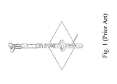
- Fig. 1 shows a prior art of a charging system.
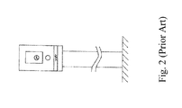
- Fig. 2 shows another prior art of a charging system.
- Fig. 3 illustrates a schematic diagram of a first embodiment of the present invention.
- Fig. 4 illustrates another schematic diagram of the first embodiment of the present invention.
- Fig. 5 illustrates a schematic diagram of a second embodiment of the present invention.
- Fig. 6 illustrates a schematic diagram of a third embodiment of the present invention.
- Fig. 7 illustrates a schematic diagram of a fourth embodiment of the present invention.
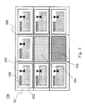
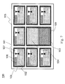
- Fig. 3 is a schematic diagram of a detachable modulized battery charging assembly 100.
- the detachable modulized battery charging assembly 100 includes seven charging units 101, a managing unit 103, a user interface unit 104 and a rack 105.
- Each of the charging unit 101 has a processor 106 and an engaging element 107.
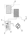
- Fig. 4 shows how the detachable modulized battery charging assembly 100 works.
- Dash-lined enclosed elements illustrate a basic charging unit of the detachable modulized battery charging assembly 100.
- Each of the charging units 101 has the same size. Therefore, the charging units 101 can be modulized.
- a rechargeable battery 102 of an electric vehicle (not shown) can be charged by removing it from the electric vehicle and then inserting it into one of the charging units 101.
- the charging unit 101 has a processor 106 and an engaging element 107.
- the processor 106 is used for retrieving data from the rechargeable battery 102.
- the data may include battery information and/or user identification.
- the battery information includes charging state, lifetime, cycle count, health state and/or serial number of the rechargeable battery.
- the user identification may include user name, user telephone number, user ID number, license plate number of the electric vehicle, and/or user password.
- the battery information and user identification of each rechargeable battery are stored in a database in the managing unit 103 or a remote server. By this way, rechargeable batteries can be easily traced while lost or stolen, and can provide a better battery management.
- a user can be notified in advance while a rechargeable battery needs to be renewed due to depletion of lifetime or defect of a battery.
- the processor 106 can retrieve data from the rechargeable battery 102 and then provide the data to the managing unit 103 for further identification.
- the managing unit 103 can identify whether the rechargeable battery 102 belongs to the user by such data retrieved from the rechargeable battery 102 because the data either includes user identification or battery information. If the data only includes battery information such as serial number but does not include user identification, then user identification can still be obtained by matching the serial number of the rechargeable battery 102 with database in the managing unit 103 or with database in a remote server.
- the possessor of the low powered rechargeable battery will no longer be recorded as the user in the database, whereas the user will instead be recorded as the possessor of the fully charged rechargeable battery in the database.
- the engaging element 107 engages the rechargeable battery 102 with the charging unit 101 until an unlock instruction is received from the managing unit 103.
- the function of unlock instruction protects the rechargeable battery 102 from being taken without permission. Only when the rechargeable battery 102 is fully charged and identification of the user is approved, i.e., it is confirmed that the low powered rechargeable battery 102 for exchange belongs to the user, the unlock instruction is given.
- the charging unit 101 is electrically linked to an external power source 200.
- the external power source 200 provides power to the charging unit 101 for the rechargeable battery 102 to be charged.
- the external power source 200 is not limited to be AC power, it DC power can also be used. In practice, it can also be a large power storage which has sufficient power stored to provide the charging unit 101.
- the managing unit 103 is actually connected to each of the charging units 101.
- the managing unit 103 controls the charging units 101, records charging statuses of the rechargeable batteries 102, and confirms identification of a user of the rechargeable batteries 102. If a rechargeable battery 102 is out of order or the user identification is not approved, the managing unit 103 will instruct the charging unit 101 not to charge the rechargeable battery 102 therein.
- the managing unit 103 includes a billing system such that a user can exchange a low powered rechargeable battery for a fully charged rechargeable battery after payments are paid. Basically, a computer can play the role of the managing unit 103.
- the user interface unit 104 is connected to the managing unit 103.
- the user interface unit 104 is mainly used to communicate with the user.
- the user interface unit 104 is a monitor. It can also be a touch panel if a two-way communication for the detachable modulized battery charging assembly 100 and users are required.
- the detachable modulized battery charging assembly 100 has seven rechargeable batteries 102 in seven charging units 101 as shown in Fig. 3 , not every fully charged rechargeable batteries 102 are allowed for the user to take, only the one that is decided by the managing unit 103 that is unlocked and able for the user to take. In other words, the user doesn't pick among the fully charged rechargeable batteries 102, the selection is made by the managing unit 103. After the selection is made by the managing unit 103, different methods can be used to indicate which of the rechargeable battery 102 is fully charged and selected for the user to take in exchange of a low powered rechargeable battery. For example, indication can be directly shown on the user interface unit 104 or simply by blinking lights set on the charging units 101 or rechargeable batteries 102.
- the rack 105 is used for accommodating the charging units 101, the managing unit 103 and the user interface unit 104.
- the rack 105 may have m columns and n rows forming shelf-like sections, wherein m and n are integers. In the present embodiment, both m and n are 3 which form nine sections. The number of the column and row are not limited to 3. It can have 5 columns with 4 rows ... etc. It should be note that the rack 105 is not limited to be a symmetric rectangular of m columns and n rows, it can even have (m x n) + 1 sections or (m x n) + 2 sections, and so on.
- the key spirit of the present invention is to make the detachable modulized battery charging assembly 100 to be able to assemble like systematic furniture such that the charging units 101, the managing unit 103 and the user interface unit 104 can be fixed together in the rack 106 in different arrangements according to different needs by having the charging units 101, the managing unit 103 and the user interface unit 104 modulized.
- the user interface unit 104 is not limited to be installed in the center of the sections. It can be put in any section of the detachable modulized battery charging assembly 100.
- the charging units 101 and the managing unit 103 can be arranged freely in the sections. Although in Fig. 3 , the managing unit 103 and the user interface unit 104 are placed separately in two different sections, they can also be placed in the same section.
- charging stations can also be in highly populated cities and not be limited to suburbs. Maintenance or replacement can also be easily performed since each component is modulized. It is also easier and cheaper for modulized components to be manufactured. Furthermore, assembly and disassembly can be much easier and convenient during shipping. Future addition of extra components can even be performed easily if needed.
- the elements of detachable modulized battery charging assembly 100 can also be further modulized in housings.
- Fig. 5 It illustrates a second embodiment.
- members having like functions will be identified by same reference numerals as that of the first embodiment and overlapping descriptions will be omitted.
- a rack 105 is not divided into shelf-like sections, and the detachable modulized battery charging assembly 100 further includes a first housing 108.
- the charging units 101, the managing unit 103 and the user interface unit 104 are individually formed inside the first housing 108 having a rectangular cuboid shape and can be stacked vertically and horizontally together to form an array of m x n.
- m and n are integers. As shown in Fig. 5 , m equals to 3 and n also equals to 3. However, it should be noted that the detachable modulized battery charging assembly 100 is not limited to be a symmetric rectangular which has an array of m x n, it can be of any shape since the first housing 108 allows each unit to be able to stack or assemble together as building blocks.
- each unit 101 has a first housing 108.
- Fig. 6 It illustrates a third embodiment. Members having like functions will be identified by same reference numerals as that of the first and second embodiments and overlapping descriptions will be omitted.
- the managing unit 103 and the user interface unit 104 are together formed in the same housing which has a rectangular cuboid shape.
- the size of the housing 108 for accommodation of the managing unit 103 and the user interface unit 104 is the same as that of for the charging units 102, and therefore, eight charging units 102 can be placed in the rack 105 to form an array of 3 x 3.
- Fig. 7 It illustrates a fourth embodiment. Members having like functions will be identified by same reference numerals as that of the previous embodiments and overlapping descriptions will be omitted.
- the managing unit 103 and the user interface unit 104 are together formed in a second housing 109 which has a size double of the size of the first housing 108 accommodating the charging units 102.
- the second housing 109 is not limited to have a size double of the size of the first housing 108, the second housing 109 can have a size multiple of the size of the first housing 108. Meaning that multiple adjacent sections can be combined into one region to accommodate the managing unit 103 and the user interface unit 104.
- the second housing 109 can even occupy the size of 2 x 2 sections.
- multiple adjacent sections which are combined into one region can also be used for accommodation of multiple charging units or another charging unit having a size multiple of the size of the charging units 102.
Abstract
Description
- The present invention relates to a battery charging assembly. More particularly, the present invention relates to a detachable modulized battery charging assembly for charging batteries of electric vehicles.
- An electric vehicle, also referred to as an electric drive vehicle, is a moving vehicle using one or more electric motors as driving system. Unlike petroleum-based transportations which are moved by the energy from gasoline, the electric vehicles use electric power as their propulsion. They won't generate waste gas. Noise is also less. During the last few decades, increased concern over the environmental impact of the petroleum-based transportation, along with the spectre of peak oil, has led to renewed interest in electric transportation. Electric power for electric vehicles can be generated from a wide range of sources, including fossil fuels, nuclear power, and renewable sources such as tidal power, solar power, and wind or any combination of those.
- In the past, an electric vehicle consumes huge electric power due to their power system. The electric power can only be transmitted to the car through overhead lines. This infrastructure makes the electric vehicles impossible to be popular. Only some of public transportations have access to it. Routes of the public transportation are strictly limited by the lined arrangement. With the development in power systems of electric vehicles, especially in batteries, the electric vehicles become a future star and more and more sources are devoted in this field.
- People are used to their existing life experience. Hence, a system for charging the batteries of the electric vehicles should be as convenient as a gas station system. When batteries of an electric car are in low battery, people can drive the car to a nearby charging station and get the batteries charged or replaced with full charged ones. Preferably, the batteries can be charged during off-peak period when cost of charge of electricity is lowest. Meanwhile, with a device to manage batteries that are used in the car, people can always know the status of the batteries and mechanics of the stations can trace the batteries for maintenance. Since the batteries are expensive, if the batteries are stolen and they can be easily found, it will be a great help for the car owners. However, the requirements mentioned above need an integrated system to fulfill.
- To fulfill the requirements, a charging station that can provide battery exchange service which allows a user to exchange a low power battery for a fully charged battery to save waiting time is desperately needed. However, to successfully manage such a battery exchange service also needs to have corresponding hardware systems to carry out such goal.
- Traditional charging station, as disclosed in
U.S. Pub. No. 2010/0013434 and2012/0022685 , mainly provides a charging booth for an electric vehicle to physically connect to, such as a gasoline station. However, for a battery in low power to be fully charged may take hours, and drivers might not have that time and patience. - Please refer to
Fig. 1 .U.S. Pub. No. 2010/0013434 provides a charging station operable in a charging cycle for charging an electric vehicle. The charging station has a key-activated controller for controlling the charging cycle. The application also relates to a key for operating the charging station. Furthermore, the application relates to a charging station having an interface for connecting the charging station to a data network. The application also relates to a charging station having a socket for receiving a plug and a key-operated locking mechanism for locking a plug in said socket. A frangible panel movable between an open position and a closed position may be provided. A processor may be provided for generating data to impose a financial charge on an individual for using the charging station. However, it still cannot fulfill the aforementioned requirements. - Please refer to
Fig. 2 .U.S. Pub. No. 2012/0022685 discloses a method for operating an electric charging station within a parking area proposes operating an electric charging station within a parking area. An identification device is used by a user when entering into the parking area, wherein the identification device provides a unique identification, wherein a current supply device of the charging station is activated by the user by using the identification device whereupon the current supply device is available for a charging process. However, it fails to fulfill the aforementioned requirements. - Hence, a solution to fulfill the above mentioned requirements for electric vehicle battery charging is desperately desired.
- This paragraph extracts and compiles some features of the present invention; other features will be disclosed in the follow-up paragraphs. It is intended to cover various modifications and similar arrangements included within the spirit and scope of the appended claims.
- In accordance with an aspect of the present invention, a detachable modulized battery charging assembly includes: a plurality of charging units, for charging a plurality of rechargeable batteries of electric vehicles while the rechargeable batteries are detachably inserted therein; a managing unit, connected to each of the charging units, for controlling the charging units, recording charging statuses of the rechargeable batteries, and confirming identification of a user; and a user interface unit, connected to the managing unit, for communicating with the user. The charging units, the managing unit and the user interface unit are modulized and can be fixed together in different arrangements.
- Preferably, the user interface unit indicates which rechargeable battery is fully charged for the user to use.
- Preferably, each of the charging units comprises a processor for retrieving data from the rechargeable battery.
- Preferably, each of the charging units comprises an engaging element for engaging the rechargeable battery with the charging unit until an unlock instruction is received from the managing unit.
- Preferably, the user interface unit comprises a monitor or a touch panel.
- Preferably, the managing unit comprises a computer.
- Preferably, the charging units, the managing unit and the user interface unit are individually formed in a rectangular cuboid shaped housing and can be stacked vertically and horizontally together to form an array of m x n, and m and n are integers.
- Preferably, the managing unit and the user interface unit are together formed in a first housing having a rectangular cuboid shape and can be stacked vertically and horizontally with the charging units which are individually formed in a second housing having a rectangular cuboid shape to form an array of m x n, and m and n are integers.
- Preferably, the detachable modulized battery charging assembly further includes a rack for accommodating the charging units, the managing unit and the user interface unit.
- Preferably, the rack is divided into m x n sections, and m and n are integers.
- Preferably, the charging units are individually placed in one of the sections.
- Preferably, the managing unit and the user interface unit are placed in the same section together.
- Preferably, the managing unit and the user interface unit are separately placed in two different sections.
- Preferably, multiple adjacent sections are combined into one region for accommodation of the managing unit and the user interface unit.
- Preferably, multiple adjacent sections are combined into one region for accommodation of multiple charging units.
- Preferably, multiple adjacent sections are combined into one region for accommodation of another charging unit having a size multiple of the size of the plurality of charging units.
- Preferably, the charging units have the same size.
-
Fig. 1 shows a prior art of a charging system. -
Fig. 2 shows another prior art of a charging system. -
Fig. 3 illustrates a schematic diagram of a first embodiment of the present invention. -
Fig. 4 illustrates another schematic diagram of the first embodiment of the present invention. -
Fig. 5 illustrates a schematic diagram of a second embodiment of the present invention. -
Fig. 6 illustrates a schematic diagram of a third embodiment of the present invention. -
Fig. 7 illustrates a schematic diagram of a fourth embodiment of the present invention. - The present invention will now be described more specifically with reference to the following embodiments.
- Please refer to
Fig. 3 andFig. 4 . A first embodiment is described.Fig. 3 is a schematic diagram of a detachable modulizedbattery charging assembly 100. In this embodiment, the detachable modulizedbattery charging assembly 100 includes seven chargingunits 101, a managingunit 103, auser interface unit 104 and arack 105. Each of the chargingunit 101 has aprocessor 106 and anengaging element 107.Fig. 4 shows how the detachable modulizedbattery charging assembly 100 works. - Please refer to
Fig. 4 first. Dash-lined enclosed elements illustrate a basic charging unit of the detachable modulizedbattery charging assembly 100. Each of the chargingunits 101 has the same size. Therefore, the chargingunits 101 can be modulized. Arechargeable battery 102 of an electric vehicle (not shown) can be charged by removing it from the electric vehicle and then inserting it into one of the chargingunits 101. - As aforementioned, the charging
unit 101 has aprocessor 106 and anengaging element 107. Theprocessor 106 is used for retrieving data from therechargeable battery 102. The data may include battery information and/or user identification. The battery information includes charging state, lifetime, cycle count, health state and/or serial number of the rechargeable battery. The user identification may include user name, user telephone number, user ID number, license plate number of the electric vehicle, and/or user password. The battery information and user identification of each rechargeable battery are stored in a database in the managingunit 103 or a remote server. By this way, rechargeable batteries can be easily traced while lost or stolen, and can provide a better battery management. For example, a user can be notified in advance while a rechargeable battery needs to be renewed due to depletion of lifetime or defect of a battery. Once arechargeable battery 102 is inserted into the chargingunit 101, theprocessor 106 can retrieve data from therechargeable battery 102 and then provide the data to the managingunit 103 for further identification. For example, the managingunit 103 can identify whether therechargeable battery 102 belongs to the user by such data retrieved from therechargeable battery 102 because the data either includes user identification or battery information. If the data only includes battery information such as serial number but does not include user identification, then user identification can still be obtained by matching the serial number of therechargeable battery 102 with database in the managingunit 103 or with database in a remote server. After the low powered rechargeable battery is exchanged with a fully charged rechargeable battery, the possessor of the low powered rechargeable battery will no longer be recorded as the user in the database, whereas the user will instead be recorded as the possessor of the fully charged rechargeable battery in the database. - The
engaging element 107 engages therechargeable battery 102 with the chargingunit 101 until an unlock instruction is received from the managingunit 103. The function of unlock instruction protects therechargeable battery 102 from being taken without permission. Only when therechargeable battery 102 is fully charged and identification of the user is approved, i.e., it is confirmed that the low poweredrechargeable battery 102 for exchange belongs to the user, the unlock instruction is given. - The charging
unit 101 is electrically linked to anexternal power source 200. Theexternal power source 200 provides power to thecharging unit 101 for therechargeable battery 102 to be charged. Theexternal power source 200 is not limited to be AC power, it DC power can also be used. In practice, it can also be a large power storage which has sufficient power stored to provide thecharging unit 101. - Although only one
charging unit 101 is shown inFig. 4 for succinct explanation, the managingunit 103 is actually connected to each of the chargingunits 101. The managingunit 103 controls the chargingunits 101, records charging statuses of therechargeable batteries 102, and confirms identification of a user of therechargeable batteries 102. If arechargeable battery 102 is out of order or the user identification is not approved, the managingunit 103 will instruct thecharging unit 101 not to charge therechargeable battery 102 therein. Ideally, the managingunit 103 includes a billing system such that a user can exchange a low powered rechargeable battery for a fully charged rechargeable battery after payments are paid. Basically, a computer can play the role of the managingunit 103. - The
user interface unit 104 is connected to the managingunit 103. Theuser interface unit 104 is mainly used to communicate with the user. In the present invention, theuser interface unit 104 is a monitor. It can also be a touch panel if a two-way communication for the detachable modulizedbattery charging assembly 100 and users are required. - When the detachable modulized
battery charging assembly 100 has sevenrechargeable batteries 102 in seven chargingunits 101 as shown inFig. 3 , not every fully chargedrechargeable batteries 102 are allowed for the user to take, only the one that is decided by the managingunit 103 that is unlocked and able for the user to take. In other words, the user doesn't pick among the fully chargedrechargeable batteries 102, the selection is made by the managingunit 103. After the selection is made by the managingunit 103, different methods can be used to indicate which of therechargeable battery 102 is fully charged and selected for the user to take in exchange of a low powered rechargeable battery. For example, indication can be directly shown on theuser interface unit 104 or simply by blinking lights set on the chargingunits 101 orrechargeable batteries 102. - The
rack 105 is used for accommodating the chargingunits 101, the managingunit 103 and theuser interface unit 104. In the present invention, therack 105 may have m columns and n rows forming shelf-like sections, wherein m and n are integers. In the present embodiment, both m and n are 3 which form nine sections. The number of the column and row are not limited to 3. It can have 5 columns with 4 rows ... etc. It should be note that therack 105 is not limited to be a symmetric rectangular of m columns and n rows, it can even have (m x n) + 1 sections or (m x n) + 2 sections, and so on. - The key spirit of the present invention is to make the detachable modulized
battery charging assembly 100 to be able to assemble like systematic furniture such that the chargingunits 101, the managingunit 103 and theuser interface unit 104 can be fixed together in therack 106 in different arrangements according to different needs by having the chargingunits 101, the managingunit 103 and theuser interface unit 104 modulized. It should be noticed that theuser interface unit 104 is not limited to be installed in the center of the sections. It can be put in any section of the detachable modulizedbattery charging assembly 100. As well, the chargingunits 101 and the managingunit 103 can be arranged freely in the sections. Although inFig. 3 , the managingunit 103 and theuser interface unit 104 are placed separately in two different sections, they can also be placed in the same section. - By providing rechargeable battery exchange service, users don't need to wait for the batteries to be charged which sufficiently reduces the parking time of each vehicle, and therefore, the charging station dose not need to have a huge land to provide enough parking spaces for electric vehicles or cafeteria for users to stay while waiting. Hence, charging stations can also be in highly populated cities and not be limited to suburbs. Maintenance or replacement can also be easily performed since each component is modulized. It is also easier and cheaper for modulized components to be manufactured. Furthermore, assembly and disassembly can be much easier and convenient during shipping. Future addition of extra components can even be performed easily if needed.
- SECOND EMBODIMENT
- According to the spirit of the present invention, the elements of detachable modulized
battery charging assembly 100 can also be further modulized in housings. Please refer toFig. 5 . It illustrates a second embodiment. In order to have an easy understanding, members having like functions will be identified by same reference numerals as that of the first embodiment and overlapping descriptions will be omitted. Differentiated from the first embodiment, arack 105 is not divided into shelf-like sections, and the detachable modulizedbattery charging assembly 100 further includes afirst housing 108. The chargingunits 101, the managingunit 103 and theuser interface unit 104 are individually formed inside thefirst housing 108 having a rectangular cuboid shape and can be stacked vertically and horizontally together to form an array of m x n. Here, m and n are integers. As shown inFig. 5 , m equals to 3 and n also equals to 3. However, it should be noted that the detachable modulizedbattery charging assembly 100 is not limited to be a symmetric rectangular which has an array of m x n, it can be of any shape since thefirst housing 108 allows each unit to be able to stack or assemble together as building blocks. - Like the first embodiment, seven charging
units 101, one managingunit 103 and oneuser interface unit 104 can be included in therack 105. However, it should be noted that therack 105 is not a requirement in this embodiment since each unit has afirst housing 108. - Please refer to
Fig. 6 . It illustrates a third embodiment. Members having like functions will be identified by same reference numerals as that of the first and second embodiments and overlapping descriptions will be omitted. Differentiated from the second embodiment, the managingunit 103 and theuser interface unit 104 are together formed in the same housing which has a rectangular cuboid shape. In this embodiment, the size of thehousing 108 for accommodation of the managingunit 103 and theuser interface unit 104 is the same as that of for the chargingunits 102, and therefore, eight chargingunits 102 can be placed in therack 105 to form an array of 3 x 3. - Please refer to
Fig. 7 . It illustrates a fourth embodiment. Members having like functions will be identified by same reference numerals as that of the previous embodiments and overlapping descriptions will be omitted. Differentiated from the third embodiment, the managingunit 103 and theuser interface unit 104 are together formed in asecond housing 109 which has a size double of the size of thefirst housing 108 accommodating the chargingunits 102. It should be noted that thesecond housing 109 is not limited to have a size double of the size of thefirst housing 108, thesecond housing 109 can have a size multiple of the size of thefirst housing 108. Meaning that multiple adjacent sections can be combined into one region to accommodate the managingunit 103 and theuser interface unit 104. Thus, thesecond housing 109 can even occupy the size of 2 x 2 sections. - Similarly, multiple adjacent sections which are combined into one region can also be used for accommodation of multiple charging units or another charging unit having a size multiple of the size of the charging
units 102. - While the invention has been described in terms of what is presently considered to be the most practical and preferred embodiments, it is to be understood that the invention needs not be limited to the disclosed embodiments. On the contrary, it is intended to cover various modifications and similar arrangements included within the spirit and scope of the appended claims, which are to be accorded with the broadest interpretation so as to encompass all such modifications and similar structures.
Claims (17)
- A detachable modulized battery charging assembly, comprising:a plurality of charging units, for charging a plurality of rechargeable batteries of electric vehicles while the rechargeable batteries are detachably inserted therein;a managing unit, connected to each of the charging units, for controlling the charging units, recording charging statuses of the rechargeable batteries, and confirming identification of a user; anda user interface unit, connected to the managing unit, for communicating with the user;wherein the charging units, the managing unit and the user interface unit are modulized and can be fixed together in different arrangements.
- The detachable modulized battery charging assembly according to claim 1, wherein the user interface unit indicates which rechargeable battery is fully charged for the user to use.
- The detachable modulized battery charging assembly according to claim 1, wherein each of the charging units comprises a processor for retrieving data from the rechargeable battery.
- The detachable modulized battery charging assembly according to claim 1, wherein each of the charging units comprises an engaging element for engaging the rechargeable battery with the charging unit until an unlock instruction is received from the managing unit.
- The detachable modulized battery charging assembly according to claim 1, wherein the user interface unit comprises a monitor or a touch panel.
- The detachable modulized battery charging assembly according to claim 1, wherein the managing unit comprises a computer.
- The detachable modulized battery charging assembly according to claim 1, wherein the charging units, the managing unit and the user interface unit are individually formed in a rectangular cuboid shaped housing and can be stacked vertically and horizontally together to form an array of m x n, and m and n are integers.
- The detachable modulized battery charging assembly according to claim 1, wherein the managing unit and the user interface unit are together formed in a first housing having a rectangular cuboid shape and can be stacked vertically and horizontally with the charging units which are individually formed in a second housing having a rectangular cuboid shape to form an array of m x n, and m and n are integers.
- The detachable modulized battery charging assembly according to claim 1, further comprising a rack for accommodating the charging units, the managing unit and the user interface unit.
- The detachable modulized battery charging assembly according to claim 9, wherein the rack is divided into m x n sections, and m and n are integers.
- The detachable modulized battery charging assembly according to claim 10, wherein the charging units are individually placed in one of the sections.
- The detachable modulized battery charging assembly according to claim 10, wherein the managing unit and the user interface unit are placed in the same section together.
- The detachable modulized battery charging assembly according to claim 10, wherein the managing unit and the user interface unit are separately placed in two different sections.
- The detachable modulized battery charging assembly according to claim 10, wherein multiple adjacent sections are combined into one region for accommodation of the managing unit and the user interface unit.
- The detachable modulized battery charging assembly according to claim 10, wherein multiple adjacent sections are combined into one region for accommodation of multiple charging units.
- The detachable modulized battery charging assembly according to claim 10, wherein multiple adjacent sections are combined into one region for accommodation of another charging unit having a size multiple of the size of the plurality of charging units.
- The detachable modulized battery charging assembly according to claim 1, wherein the plurality of charging units have the same size.
Priority Applications (5)
| Application Number | Priority Date | Filing Date | Title |
|---|---|---|---|
| EP12163567.6A EP2651002B1 (en) | 2012-04-10 | 2012-04-10 | Detachable modulized battery charging assembly |
| US13/443,102 US9096141B2 (en) | 2012-04-10 | 2012-04-10 | Detachable modularized battery charging assembly |
| ES12163567T ES2570854T3 (en) | 2012-04-10 | 2012-04-10 | Removable modular battery charging set |
| TW101125582A TWI565186B (en) | 2012-04-10 | 2012-07-16 | Detachable modulized battery charging assembly |
| CN201210248404.3A CN103368218B (en) | 2012-04-10 | 2012-07-17 | Detachable module electrochemical cell charging combination |
Applications Claiming Priority (2)
| Application Number | Priority Date | Filing Date | Title |
|---|---|---|---|
| EP12163567.6A EP2651002B1 (en) | 2012-04-10 | 2012-04-10 | Detachable modulized battery charging assembly |
| US13/443,102 US9096141B2 (en) | 2012-04-10 | 2012-04-10 | Detachable modularized battery charging assembly |
Publications (2)
| Publication Number | Publication Date |
|---|---|
| EP2651002A1 true EP2651002A1 (en) | 2013-10-16 |
| EP2651002B1 EP2651002B1 (en) | 2016-03-09 |
Family
ID=65724110
Family Applications (1)
| Application Number | Title | Priority Date | Filing Date |
|---|---|---|---|
| EP12163567.6A Active EP2651002B1 (en) | 2012-04-10 | 2012-04-10 | Detachable modulized battery charging assembly |
Country Status (5)
| Country | Link |
|---|---|
| US (1) | US9096141B2 (en) |
| EP (1) | EP2651002B1 (en) |
| CN (1) | CN103368218B (en) |
| ES (1) | ES2570854T3 (en) |
| TW (1) | TWI565186B (en) |
Cited By (5)
| Publication number | Priority date | Publication date | Assignee | Title |
|---|---|---|---|---|
| WO2016036742A1 (en) | 2014-09-04 | 2016-03-10 | Gogoro Inc. | Apparatus, system, and method for vending, charging, and two-way distribution of electrical energy storage devices |
| DE102016104989A1 (en) * | 2016-03-07 | 2017-09-07 | Deutsche Post Ag | Interim storage for battery units |
| DE102017105632A1 (en) | 2017-03-16 | 2018-09-20 | Dr. Ing. H.C. F. Porsche Ag | Charging station system for electric vehicles |
| WO2021024244A1 (en) * | 2019-08-07 | 2021-02-11 | Moshe Amzaleg | A portable device and an apparatus for replacing used battery of the portable device |
| EP4012879A1 (en) * | 2020-12-10 | 2022-06-15 | Andreas Stihl AG & Co. KG | Method and system for releasing an output of a motor-driven machining tool and / or a battery pack for supplying a machining tool with electrical drive power to a delivery point |
Families Citing this family (9)
| Publication number | Priority date | Publication date | Assignee | Title |
|---|---|---|---|---|
| WO2013142154A1 (en) | 2012-03-20 | 2013-09-26 | Tricopian, Llc | Two-way exchange vending |
| JP5641024B2 (en) * | 2012-08-07 | 2014-12-17 | トヨタ自動車株式会社 | Battery management system and battery replacement method |
| EP2909913A4 (en) * | 2012-10-19 | 2016-05-11 | Tricopian Llc | System and method for providing rechargeable batteries |
| WO2015027215A1 (en) | 2013-08-22 | 2015-02-26 | Tricopian, Llc | Standardized rechargeable battery cell |
| US10846674B2 (en) * | 2016-06-15 | 2020-11-24 | Dignan Rayner | Rechargeable devices and kiosks for same |
| TW201939419A (en) * | 2018-03-02 | 2019-10-01 | 光陽工業股份有限公司 | Power supply device exchange method and sales end mobile device thereof including a sales end communication module and a sales end processing module |
| CN208774573U (en) * | 2018-03-13 | 2019-04-23 | 蔚来汽车有限公司 | Charhing unit, electrical changing station |
| JP7405824B2 (en) * | 2018-07-20 | 2023-12-26 | 奥動新能源汽車科技有限公司 | Battery exchange control system and method |
| US11791630B1 (en) | 2020-05-01 | 2023-10-17 | Zero Nox, Inc. | Multi-functional building power management |
Citations (10)
| Publication number | Priority date | Publication date | Assignee | Title |
|---|---|---|---|---|
| EP0693813A1 (en) * | 1994-07-22 | 1996-01-24 | Chen-Chi Yang | Battery vending system |
| WO1999057794A1 (en) * | 1998-04-30 | 1999-11-11 | P.M.G. S.N.C. Dei F.Lli Paganini Mauro E Giorgio | Station for recharging and automatic identification of plural types of batteries |
| FR2780569A1 (en) * | 1998-06-24 | 1999-12-31 | Honda Motor Co Ltd | Automatic optimisation of battery recharging, particularly applicable to systems supporting battery electric vehicles |
| US6154006A (en) * | 1997-04-18 | 2000-11-28 | Honda Giken Kogyo Kabushiki Kaisha | Battery rental system |
| US6218796B1 (en) * | 1998-10-06 | 2001-04-17 | Mobile Design Corporation | Storage cart for rechargeable devices |
| GB2428525A (en) * | 2005-07-20 | 2007-01-31 | Peter Denness | A battery charging cabinet |
| US20070188130A1 (en) * | 2006-02-09 | 2007-08-16 | Scheucher Karl F | Scalable intelligent power supply system and method |
| US20100013434A1 (en) | 2006-06-08 | 2010-01-21 | Elektromotive Ltd. | Charging station |
| US20120022685A1 (en) | 2010-07-21 | 2012-01-26 | Scheidt & Bachmann Gmbh | Method for operating an electric charging station |
| EP2428939A1 (en) * | 2010-09-08 | 2012-03-14 | Siemens Aktiengesellschaft | Automatic service machine for using and/or charging an energy storage device for an electric bicycle |
Family Cites Families (6)
| Publication number | Priority date | Publication date | Assignee | Title |
|---|---|---|---|---|
| EP0950015A4 (en) * | 1996-11-12 | 2000-02-02 | Unlimited Range Electric Car S | Battery charging and exchange system for electrically powered vehicles |
| JP2000090348A (en) | 1998-09-09 | 2000-03-31 | Honda Motor Co Ltd | Battery charging device and battery returning device |
| US20030141840A1 (en) * | 2002-01-29 | 2003-07-31 | Grant Sanders | Recharging system for personal electronic devices |
| US7884502B2 (en) * | 2007-08-09 | 2011-02-08 | Zerobase Energy, Llc | Deployable power supply system |
| US8963481B2 (en) * | 2011-05-25 | 2015-02-24 | Green Charge Networks | Charging service vehicles and methods using modular batteries |
| TWI485572B (en) * | 2011-07-26 | 2015-05-21 | 睿能創意公司 | Apparatus, method and article for physical security of power storage devices in vehicles |
-
2012
- 2012-04-10 ES ES12163567T patent/ES2570854T3/en active Active
- 2012-04-10 EP EP12163567.6A patent/EP2651002B1/en active Active
- 2012-04-10 US US13/443,102 patent/US9096141B2/en active Active
- 2012-07-16 TW TW101125582A patent/TWI565186B/en active
- 2012-07-17 CN CN201210248404.3A patent/CN103368218B/en active Active
Patent Citations (10)
| Publication number | Priority date | Publication date | Assignee | Title |
|---|---|---|---|---|
| EP0693813A1 (en) * | 1994-07-22 | 1996-01-24 | Chen-Chi Yang | Battery vending system |
| US6154006A (en) * | 1997-04-18 | 2000-11-28 | Honda Giken Kogyo Kabushiki Kaisha | Battery rental system |
| WO1999057794A1 (en) * | 1998-04-30 | 1999-11-11 | P.M.G. S.N.C. Dei F.Lli Paganini Mauro E Giorgio | Station for recharging and automatic identification of plural types of batteries |
| FR2780569A1 (en) * | 1998-06-24 | 1999-12-31 | Honda Motor Co Ltd | Automatic optimisation of battery recharging, particularly applicable to systems supporting battery electric vehicles |
| US6218796B1 (en) * | 1998-10-06 | 2001-04-17 | Mobile Design Corporation | Storage cart for rechargeable devices |
| GB2428525A (en) * | 2005-07-20 | 2007-01-31 | Peter Denness | A battery charging cabinet |
| US20070188130A1 (en) * | 2006-02-09 | 2007-08-16 | Scheucher Karl F | Scalable intelligent power supply system and method |
| US20100013434A1 (en) | 2006-06-08 | 2010-01-21 | Elektromotive Ltd. | Charging station |
| US20120022685A1 (en) | 2010-07-21 | 2012-01-26 | Scheidt & Bachmann Gmbh | Method for operating an electric charging station |
| EP2428939A1 (en) * | 2010-09-08 | 2012-03-14 | Siemens Aktiengesellschaft | Automatic service machine for using and/or charging an energy storage device for an electric bicycle |
Cited By (9)
| Publication number | Priority date | Publication date | Assignee | Title |
|---|---|---|---|---|
| WO2016036742A1 (en) | 2014-09-04 | 2016-03-10 | Gogoro Inc. | Apparatus, system, and method for vending, charging, and two-way distribution of electrical energy storage devices |
| US10040359B2 (en) | 2014-09-04 | 2018-08-07 | Gogoro Inc. | Apparatus, system, and method for vending, charging, and two-way distribution of electrical energy storage devices |
| EP3188926A4 (en) * | 2014-09-04 | 2019-06-19 | Gogoro Inc. | Apparatus, system, and method for vending, charging, and two-way distribution of electrical energy storage devices |
| DE102016104989A1 (en) * | 2016-03-07 | 2017-09-07 | Deutsche Post Ag | Interim storage for battery units |
| CN107171377A (en) * | 2016-03-07 | 2017-09-15 | 德国邮政股份公司 | Intermediate storage facility for battery unit |
| DE102017105632A1 (en) | 2017-03-16 | 2018-09-20 | Dr. Ing. H.C. F. Porsche Ag | Charging station system for electric vehicles |
| US10457153B2 (en) | 2017-03-16 | 2019-10-29 | Dr. Ing. H.C. F. Porsche Aktiengesellschaft | Charging station system for electric vehicles with interconnections between power and cooling main components |
| WO2021024244A1 (en) * | 2019-08-07 | 2021-02-11 | Moshe Amzaleg | A portable device and an apparatus for replacing used battery of the portable device |
| EP4012879A1 (en) * | 2020-12-10 | 2022-06-15 | Andreas Stihl AG & Co. KG | Method and system for releasing an output of a motor-driven machining tool and / or a battery pack for supplying a machining tool with electrical drive power to a delivery point |
Also Published As
| Publication number | Publication date |
|---|---|
| TWI565186B (en) | 2017-01-01 |
| US9096141B2 (en) | 2015-08-04 |
| ES2570854T3 (en) | 2016-05-20 |
| TW201342295A (en) | 2013-10-16 |
| CN103368218A (en) | 2013-10-23 |
| EP2651002B1 (en) | 2016-03-09 |
| US20130264996A1 (en) | 2013-10-10 |
| CN103368218B (en) | 2015-10-21 |
Similar Documents
| Publication | Publication Date | Title |
|---|---|---|
| US9096141B2 (en) | Detachable modularized battery charging assembly | |
| USRE46166E1 (en) | Charging system of electric vehicle and method for charging electric vehicle | |
| US9567025B2 (en) | System and method for bicycle sharing and rental | |
| EP2182575B1 (en) | Cartridge battery, management device, battery system, management method, and program | |
| US20100292877A1 (en) | Comprehensive engineering / operation system for electric vehicle and smart networked and decentralized power storage | |
| US20210138921A1 (en) | Modular charging station for urban micro-mobility vehicles | |
| ES2802906T3 (en) | Modular system for the collection and distribution of electrical storage devices | |
| TWI546761B (en) | Method, machine and non-transitory computer-readable medium for collection, charging and distributing power storage devices | |
| TWI486909B (en) | Apparatus, method and article for providing vehicle diagnostic data | |
| US9310855B2 (en) | Flexible data center and methods for deployment | |
| CN214396452U (en) | Electricity changing cabinet, electricity changing system and combined adapter | |
| US20120303259A1 (en) | Providing Roadside Charging Services | |
| US9543783B2 (en) | Charging module and rechargeable battery assembly for electric vehicle | |
| CN101834455B (en) | Charging station system of electric automobile and matched charging method thereof | |
| US20100223858A1 (en) | Data center facility for multi-tenant environment | |
| US10926644B1 (en) | Compact electric vehicle fast charger with energy storage | |
| KR20210142153A (en) | Method and apparatus for modular charging station | |
| KR102328844B1 (en) | A movable charging device for electric vehicles | |
| JP2016208692A (en) | On-vehicle battery system | |
| CN112687055A (en) | Thing networking sharing locker | |
| CN106541849A (en) | A kind of new-energy automobile charging pile based on Internet of Things | |
| WO2021094909A1 (en) | Electric recharging station and integrated system for a plurality of such recharging stations | |
| CN110641307A (en) | System, method and device for appropriate power distribution and conversion | |
| KR20100001311U (en) | Station for lending/collecting of the bicycle | |
| CN109501762A (en) | Electrical changing station |
Legal Events
| Date | Code | Title | Description |
|---|---|---|---|
| PUAI | Public reference made under article 153(3) epc to a published international application that has entered the european phase |
Free format text: ORIGINAL CODE: 0009012 |
|
| AK | Designated contracting states |
Kind code of ref document: A1 Designated state(s): AL AT BE BG CH CY CZ DE DK EE ES FI FR GB GR HR HU IE IS IT LI LT LU LV MC MK MT NL NO PL PT RO RS SE SI SK SM TR |
|
| AX | Request for extension of the european patent |
Extension state: BA ME |
|
| 17P | Request for examination filed |
Effective date: 20140326 |
|
| RBV | Designated contracting states (corrected) |
Designated state(s): AL AT BE BG CH CY CZ DE DK EE ES FI FR GB GR HR HU IE IS IT LI LT LU LV MC MK MT NL NO PL PT RO RS SE SI SK SM TR |
|
| GRAP | Despatch of communication of intention to grant a patent |
Free format text: ORIGINAL CODE: EPIDOSNIGR1 |
|
| INTG | Intention to grant announced |
Effective date: 20150930 |
|
| GRAS | Grant fee paid |
Free format text: ORIGINAL CODE: EPIDOSNIGR3 |
|
| GRAA | (expected) grant |
Free format text: ORIGINAL CODE: 0009210 |
|
| AK | Designated contracting states |
Kind code of ref document: B1 Designated state(s): AL AT BE BG CH CY CZ DE DK EE ES FI FR GB GR HR HU IE IS IT LI LT LU LV MC MK MT NL NO PL PT RO RS SE SI SK SM TR |
|
| REG | Reference to a national code |
Ref country code: GB Ref legal event code: FG4D |
|
| REG | Reference to a national code |
Ref country code: AT Ref legal event code: REF Ref document number: 780138 Country of ref document: AT Kind code of ref document: T Effective date: 20160315 Ref country code: CH Ref legal event code: EP |
|
| REG | Reference to a national code |
Ref country code: IE Ref legal event code: FG4D |
|
| REG | Reference to a national code |
Ref country code: DE Ref legal event code: R096 Ref document number: 602012015343 Country of ref document: DE |
|
| REG | Reference to a national code |
Ref country code: FR Ref legal event code: PLFP Year of fee payment: 5 |
|
| REG | Reference to a national code |
Ref country code: ES Ref legal event code: FG2A Ref document number: 2570854 Country of ref document: ES Kind code of ref document: T3 Effective date: 20160520 |
|
| REG | Reference to a national code |
Ref country code: NL Ref legal event code: FP |
|
| REG | Reference to a national code |
Ref country code: LT Ref legal event code: MG4D |
|
| PG25 | Lapsed in a contracting state [announced via postgrant information from national office to epo] |
Ref country code: NO Free format text: LAPSE BECAUSE OF FAILURE TO SUBMIT A TRANSLATION OF THE DESCRIPTION OR TO PAY THE FEE WITHIN THE PRESCRIBED TIME-LIMIT Effective date: 20160609 Ref country code: HR Free format text: LAPSE BECAUSE OF FAILURE TO SUBMIT A TRANSLATION OF THE DESCRIPTION OR TO PAY THE FEE WITHIN THE PRESCRIBED TIME-LIMIT Effective date: 20160309 Ref country code: GR Free format text: LAPSE BECAUSE OF FAILURE TO SUBMIT A TRANSLATION OF THE DESCRIPTION OR TO PAY THE FEE WITHIN THE PRESCRIBED TIME-LIMIT Effective date: 20160610 |
|
| REG | Reference to a national code |
Ref country code: AT Ref legal event code: MK05 Ref document number: 780138 Country of ref document: AT Kind code of ref document: T Effective date: 20160309 |
|
| PG25 | Lapsed in a contracting state [announced via postgrant information from national office to epo] |
Ref country code: BE Free format text: LAPSE BECAUSE OF NON-PAYMENT OF DUE FEES Effective date: 20160430 Ref country code: RS Free format text: LAPSE BECAUSE OF FAILURE TO SUBMIT A TRANSLATION OF THE DESCRIPTION OR TO PAY THE FEE WITHIN THE PRESCRIBED TIME-LIMIT Effective date: 20160309 Ref country code: LV Free format text: LAPSE BECAUSE OF FAILURE TO SUBMIT A TRANSLATION OF THE DESCRIPTION OR TO PAY THE FEE WITHIN THE PRESCRIBED TIME-LIMIT Effective date: 20160309 Ref country code: PL Free format text: LAPSE BECAUSE OF FAILURE TO SUBMIT A TRANSLATION OF THE DESCRIPTION OR TO PAY THE FEE WITHIN THE PRESCRIBED TIME-LIMIT Effective date: 20160309 Ref country code: LT Free format text: LAPSE BECAUSE OF FAILURE TO SUBMIT A TRANSLATION OF THE DESCRIPTION OR TO PAY THE FEE WITHIN THE PRESCRIBED TIME-LIMIT Effective date: 20160309 Ref country code: SE Free format text: LAPSE BECAUSE OF FAILURE TO SUBMIT A TRANSLATION OF THE DESCRIPTION OR TO PAY THE FEE WITHIN THE PRESCRIBED TIME-LIMIT Effective date: 20160309 |
|
| PG25 | Lapsed in a contracting state [announced via postgrant information from national office to epo] |
Ref country code: IS Free format text: LAPSE BECAUSE OF FAILURE TO SUBMIT A TRANSLATION OF THE DESCRIPTION OR TO PAY THE FEE WITHIN THE PRESCRIBED TIME-LIMIT Effective date: 20160709 Ref country code: EE Free format text: LAPSE BECAUSE OF FAILURE TO SUBMIT A TRANSLATION OF THE DESCRIPTION OR TO PAY THE FEE WITHIN THE PRESCRIBED TIME-LIMIT Effective date: 20160309 |
|
| PG25 | Lapsed in a contracting state [announced via postgrant information from national office to epo] |
Ref country code: CZ Free format text: LAPSE BECAUSE OF FAILURE TO SUBMIT A TRANSLATION OF THE DESCRIPTION OR TO PAY THE FEE WITHIN THE PRESCRIBED TIME-LIMIT Effective date: 20160309 Ref country code: SK Free format text: LAPSE BECAUSE OF FAILURE TO SUBMIT A TRANSLATION OF THE DESCRIPTION OR TO PAY THE FEE WITHIN THE PRESCRIBED TIME-LIMIT Effective date: 20160309 Ref country code: SM Free format text: LAPSE BECAUSE OF FAILURE TO SUBMIT A TRANSLATION OF THE DESCRIPTION OR TO PAY THE FEE WITHIN THE PRESCRIBED TIME-LIMIT Effective date: 20160309 Ref country code: AT Free format text: LAPSE BECAUSE OF FAILURE TO SUBMIT A TRANSLATION OF THE DESCRIPTION OR TO PAY THE FEE WITHIN THE PRESCRIBED TIME-LIMIT Effective date: 20160309 Ref country code: PT Free format text: LAPSE BECAUSE OF FAILURE TO SUBMIT A TRANSLATION OF THE DESCRIPTION OR TO PAY THE FEE WITHIN THE PRESCRIBED TIME-LIMIT Effective date: 20160711 Ref country code: RO Free format text: LAPSE BECAUSE OF FAILURE TO SUBMIT A TRANSLATION OF THE DESCRIPTION OR TO PAY THE FEE WITHIN THE PRESCRIBED TIME-LIMIT Effective date: 20160309 |
|
| REG | Reference to a national code |
Ref country code: CH Ref legal event code: PL |
|
| REG | Reference to a national code |
Ref country code: DE Ref legal event code: R097 Ref document number: 602012015343 Country of ref document: DE |
|
| PG25 | Lapsed in a contracting state [announced via postgrant information from national office to epo] |
Ref country code: BE Free format text: LAPSE BECAUSE OF FAILURE TO SUBMIT A TRANSLATION OF THE DESCRIPTION OR TO PAY THE FEE WITHIN THE PRESCRIBED TIME-LIMIT Effective date: 20160309 |
|
| PLBE | No opposition filed within time limit |
Free format text: ORIGINAL CODE: 0009261 |
|
| STAA | Information on the status of an ep patent application or granted ep patent |
Free format text: STATUS: NO OPPOSITION FILED WITHIN TIME LIMIT |
|
| REG | Reference to a national code |
Ref country code: IE Ref legal event code: MM4A |
|
| PG25 | Lapsed in a contracting state [announced via postgrant information from national office to epo] |
Ref country code: DK Free format text: LAPSE BECAUSE OF FAILURE TO SUBMIT A TRANSLATION OF THE DESCRIPTION OR TO PAY THE FEE WITHIN THE PRESCRIBED TIME-LIMIT Effective date: 20160309 Ref country code: LI Free format text: LAPSE BECAUSE OF NON-PAYMENT OF DUE FEES Effective date: 20160430 Ref country code: CH Free format text: LAPSE BECAUSE OF NON-PAYMENT OF DUE FEES Effective date: 20160430 |
|
| 26N | No opposition filed |
Effective date: 20161212 |
|
| PG25 | Lapsed in a contracting state [announced via postgrant information from national office to epo] |
Ref country code: BG Free format text: LAPSE BECAUSE OF FAILURE TO SUBMIT A TRANSLATION OF THE DESCRIPTION OR TO PAY THE FEE WITHIN THE PRESCRIBED TIME-LIMIT Effective date: 20160609 |
|
| GBPC | Gb: european patent ceased through non-payment of renewal fee |
Effective date: 20160609 |
|
| REG | Reference to a national code |
Ref country code: FR Ref legal event code: PLFP Year of fee payment: 6 |
|
| PG25 | Lapsed in a contracting state [announced via postgrant information from national office to epo] |
Ref country code: SI Free format text: LAPSE BECAUSE OF FAILURE TO SUBMIT A TRANSLATION OF THE DESCRIPTION OR TO PAY THE FEE WITHIN THE PRESCRIBED TIME-LIMIT Effective date: 20160309 Ref country code: GB Free format text: LAPSE BECAUSE OF NON-PAYMENT OF DUE FEES Effective date: 20160609 Ref country code: IE Free format text: LAPSE BECAUSE OF NON-PAYMENT OF DUE FEES Effective date: 20160410 |
|
| REG | Reference to a national code |
Ref country code: FR Ref legal event code: PLFP Year of fee payment: 7 |
|
| PG25 | Lapsed in a contracting state [announced via postgrant information from national office to epo] |
Ref country code: HU Free format text: LAPSE BECAUSE OF FAILURE TO SUBMIT A TRANSLATION OF THE DESCRIPTION OR TO PAY THE FEE WITHIN THE PRESCRIBED TIME-LIMIT; INVALID AB INITIO Effective date: 20120410 Ref country code: CY Free format text: LAPSE BECAUSE OF FAILURE TO SUBMIT A TRANSLATION OF THE DESCRIPTION OR TO PAY THE FEE WITHIN THE PRESCRIBED TIME-LIMIT Effective date: 20160309 |
|
| PG25 | Lapsed in a contracting state [announced via postgrant information from national office to epo] |
Ref country code: MK Free format text: LAPSE BECAUSE OF FAILURE TO SUBMIT A TRANSLATION OF THE DESCRIPTION OR TO PAY THE FEE WITHIN THE PRESCRIBED TIME-LIMIT Effective date: 20160309 Ref country code: MT Free format text: LAPSE BECAUSE OF NON-PAYMENT OF DUE FEES Effective date: 20160430 Ref country code: LU Free format text: LAPSE BECAUSE OF NON-PAYMENT OF DUE FEES Effective date: 20160410 Ref country code: TR Free format text: LAPSE BECAUSE OF FAILURE TO SUBMIT A TRANSLATION OF THE DESCRIPTION OR TO PAY THE FEE WITHIN THE PRESCRIBED TIME-LIMIT Effective date: 20160309 Ref country code: MC Free format text: LAPSE BECAUSE OF FAILURE TO SUBMIT A TRANSLATION OF THE DESCRIPTION OR TO PAY THE FEE WITHIN THE PRESCRIBED TIME-LIMIT Effective date: 20160309 |
|
| PG25 | Lapsed in a contracting state [announced via postgrant information from national office to epo] |
Ref country code: AL Free format text: LAPSE BECAUSE OF FAILURE TO SUBMIT A TRANSLATION OF THE DESCRIPTION OR TO PAY THE FEE WITHIN THE PRESCRIBED TIME-LIMIT Effective date: 20160309 |
|
| PGFP | Annual fee paid to national office [announced via postgrant information from national office to epo] |
Ref country code: FR Payment date: 20230309 Year of fee payment: 12 |
|
| PGFP | Annual fee paid to national office [announced via postgrant information from national office to epo] |
Ref country code: NL Payment date: 20230406 Year of fee payment: 12 |
|
| PGFP | Annual fee paid to national office [announced via postgrant information from national office to epo] |
Ref country code: IT Payment date: 20230406 Year of fee payment: 12 Ref country code: DE Payment date: 20230406 Year of fee payment: 12 |
|
| PGFP | Annual fee paid to national office [announced via postgrant information from national office to epo] |
Ref country code: FI Payment date: 20230406 Year of fee payment: 12 |
|
| PGFP | Annual fee paid to national office [announced via postgrant information from national office to epo] |
Ref country code: ES Payment date: 20230713 Year of fee payment: 12 |