EP2650607A1 - Modular LED light - Google Patents
Modular LED light Download PDFInfo
- Publication number
- EP2650607A1 EP2650607A1 EP12164193.0A EP12164193A EP2650607A1 EP 2650607 A1 EP2650607 A1 EP 2650607A1 EP 12164193 A EP12164193 A EP 12164193A EP 2650607 A1 EP2650607 A1 EP 2650607A1
- Authority
- EP
- European Patent Office
- Prior art keywords
- controller
- connector
- light
- cable duct
- light module
- Prior art date
- Legal status (The legal status is an assumption and is not a legal conclusion. Google has not performed a legal analysis and makes no representation as to the accuracy of the status listed.)
- Granted
Links
Images


Classifications
-
- F—MECHANICAL ENGINEERING; LIGHTING; HEATING; WEAPONS; BLASTING
- F21—LIGHTING
- F21V—FUNCTIONAL FEATURES OR DETAILS OF LIGHTING DEVICES OR SYSTEMS THEREOF; STRUCTURAL COMBINATIONS OF LIGHTING DEVICES WITH OTHER ARTICLES, NOT OTHERWISE PROVIDED FOR
- F21V31/00—Gas-tight or water-tight arrangements
- F21V31/005—Sealing arrangements therefor
-
- F—MECHANICAL ENGINEERING; LIGHTING; HEATING; WEAPONS; BLASTING
- F21—LIGHTING
- F21K—NON-ELECTRIC LIGHT SOURCES USING LUMINESCENCE; LIGHT SOURCES USING ELECTROCHEMILUMINESCENCE; LIGHT SOURCES USING CHARGES OF COMBUSTIBLE MATERIAL; LIGHT SOURCES USING SEMICONDUCTOR DEVICES AS LIGHT-GENERATING ELEMENTS; LIGHT SOURCES NOT OTHERWISE PROVIDED FOR
- F21K9/00—Light sources using semiconductor devices as light-generating elements, e.g. using light-emitting diodes [LED] or lasers
- F21K9/20—Light sources comprising attachment means
-
- F—MECHANICAL ENGINEERING; LIGHTING; HEATING; WEAPONS; BLASTING
- F21—LIGHTING
- F21V—FUNCTIONAL FEATURES OR DETAILS OF LIGHTING DEVICES OR SYSTEMS THEREOF; STRUCTURAL COMBINATIONS OF LIGHTING DEVICES WITH OTHER ARTICLES, NOT OTHERWISE PROVIDED FOR
- F21V15/00—Protecting lighting devices from damage
- F21V15/01—Housings, e.g. material or assembling of housing parts
-
- F—MECHANICAL ENGINEERING; LIGHTING; HEATING; WEAPONS; BLASTING
- F21—LIGHTING
- F21V—FUNCTIONAL FEATURES OR DETAILS OF LIGHTING DEVICES OR SYSTEMS THEREOF; STRUCTURAL COMBINATIONS OF LIGHTING DEVICES WITH OTHER ARTICLES, NOT OTHERWISE PROVIDED FOR
- F21V19/00—Fastening of light sources or lamp holders
- F21V19/001—Fastening of light sources or lamp holders the light sources being semiconductors devices, e.g. LEDs
- F21V19/003—Fastening of light source holders, e.g. of circuit boards or substrates holding light sources
- F21V19/005—Fastening of light source holders, e.g. of circuit boards or substrates holding light sources by permanent fixing means, e.g. gluing, riveting or embedding in a potting compound
-
- F—MECHANICAL ENGINEERING; LIGHTING; HEATING; WEAPONS; BLASTING
- F21—LIGHTING
- F21V—FUNCTIONAL FEATURES OR DETAILS OF LIGHTING DEVICES OR SYSTEMS THEREOF; STRUCTURAL COMBINATIONS OF LIGHTING DEVICES WITH OTHER ARTICLES, NOT OTHERWISE PROVIDED FOR
- F21V23/00—Arrangement of electric circuit elements in or on lighting devices
- F21V23/001—Arrangement of electric circuit elements in or on lighting devices the elements being electrical wires or cables
- F21V23/002—Arrangements of cables or conductors inside a lighting device, e.g. means for guiding along parts of the housing or in a pivoting arm
-
- F—MECHANICAL ENGINEERING; LIGHTING; HEATING; WEAPONS; BLASTING
- F21—LIGHTING
- F21V—FUNCTIONAL FEATURES OR DETAILS OF LIGHTING DEVICES OR SYSTEMS THEREOF; STRUCTURAL COMBINATIONS OF LIGHTING DEVICES WITH OTHER ARTICLES, NOT OTHERWISE PROVIDED FOR
- F21V23/00—Arrangement of electric circuit elements in or on lighting devices
- F21V23/003—Arrangement of electric circuit elements in or on lighting devices the elements being electronics drivers or controllers for operating the light source, e.g. for a LED array
- F21V23/007—Arrangement of electric circuit elements in or on lighting devices the elements being electronics drivers or controllers for operating the light source, e.g. for a LED array enclosed in a casing
- F21V23/009—Arrangement of electric circuit elements in or on lighting devices the elements being electronics drivers or controllers for operating the light source, e.g. for a LED array enclosed in a casing the casing being inside the housing of the lighting device
-
- F—MECHANICAL ENGINEERING; LIGHTING; HEATING; WEAPONS; BLASTING
- F21—LIGHTING
- F21V—FUNCTIONAL FEATURES OR DETAILS OF LIGHTING DEVICES OR SYSTEMS THEREOF; STRUCTURAL COMBINATIONS OF LIGHTING DEVICES WITH OTHER ARTICLES, NOT OTHERWISE PROVIDED FOR
- F21V23/00—Arrangement of electric circuit elements in or on lighting devices
- F21V23/06—Arrangement of electric circuit elements in or on lighting devices the elements being coupling devices, e.g. connectors
-
- F—MECHANICAL ENGINEERING; LIGHTING; HEATING; WEAPONS; BLASTING
- F21—LIGHTING
- F21V—FUNCTIONAL FEATURES OR DETAILS OF LIGHTING DEVICES OR SYSTEMS THEREOF; STRUCTURAL COMBINATIONS OF LIGHTING DEVICES WITH OTHER ARTICLES, NOT OTHERWISE PROVIDED FOR
- F21V3/00—Globes; Bowls; Cover glasses
-
- F—MECHANICAL ENGINEERING; LIGHTING; HEATING; WEAPONS; BLASTING
- F21—LIGHTING
- F21Y—INDEXING SCHEME ASSOCIATED WITH SUBCLASSES F21K, F21L, F21S and F21V, RELATING TO THE FORM OR THE KIND OF THE LIGHT SOURCES OR OF THE COLOUR OF THE LIGHT EMITTED
- F21Y2115/00—Light-generating elements of semiconductor light sources
- F21Y2115/10—Light-emitting diodes [LED]
Definitions
- the invention relates to a modular LED-light comprising a housing for a controller and a light module according to the preamble of claim 1.
- US 2006/0262545 discloses a modular LED light.
- the LED light has a housing with a compartment for insertion of a controller.
- the controller is connected by wirings to a power line and to a data bus, e.g. Ethernet via RJ45 jacks.
- the controller is connected to a LED module by an output wiring.
- the output wiring may end in a socket for connector of a LED module.
- the socket is attached to a base, the latter being supported by the housing.
- the housing is inserted into an aperture in a ceiling and fixed to the ceiling. Subsequently the wiring is connected to the power line, a control input wire and inserted via an opening of the housing into the compartment.
- the controller reaches its final position, it is attached to the housing by a clamping element.
- the invention is based on the observation that LED-lights for wall or ceilings often have a modular design. However, they are complicated to mount and in most cases mounting require a certified electrician for connecting the wires.
- the problem to be solved by the invention is to provide an easy to mount modular LED-light that is in particular suited for being arranged in a row with other lights, to form a "light strip", i.e., a row of lights.
- the light comprises at least housing for a light module and a controller.
- the controller preferably has a casing and is electrically connected to a power line and to the light module.
- the housing preferably comprises a cable duct for housing the at least one power line.
- the cable duct may comprise at least a first connector being attached to the cable duct.
- the controller may comprise at least a second connector and preferably as well third connector.
- the second connector is complementary to the first connector.
- the cable duct and/or the controller preferably comprise a first support structure for attaching the cable duct with the controller. The first support structure attaches the cable duct to the controller when the first connector and the second connector reach their final plugged position. This permits to electrically connect and to mechanically attach the controller and the cable duct simultaneously.
- the second connector can be plugged into the first connector from the outside of the cable duct, i.e., the first connector can be accessed without opening the cable duct. Thereby, the power line and the "user interface side" of the first connector are separated.
- the light may further comprise a controller with at least a casing, a second connector and a third connector, wherein the second connector is complementary to the first connector and wherein the second connector and the third connector are each pluggable from the outside of the cable duct.
- a controller with at least a casing, a second connector and a third connector, wherein the second connector is complementary to the first connector and wherein the second connector and the third connector are each pluggable from the outside of the cable duct.
- At least one of the second and third connectors is preferably fixed to the casing of the controller.
- the second and/or third connectors may be integrated in the casing. Their pins and/or female counterparts may be mounted directly to a circuit board of the controller.
- the light module may comprise a fourth connector. If the latter is complementary to the third connector and pluggable from the outside of the casing, the light module can be connected to the controller by simply plugging the third and fourth connector.
- the cable duct and/or the controller comprise(s) a first support structure for attaching the cable duct with the controller, wherein the first support structure attaches the cable duct with the controller, when the first connector and the second connector reach their final positions.
- the controller is automatically attached to the cable duct.
- the first support structure may be integrated in the first and/or second connectors.
- the first support structure is separate, but preferably the cable duct and the controller are attached to each other at the same time the first and second connectors are connected to each other.
- the first support structure may interlock the connection of the first and second connectors.
- the light module and/or the controller comprise a second support structure for attaching the light module with the controller, wherein the second support structure attaches the light module with the controller, when the third connector and the fourth connector reach their final plugged positions.
- This permits to simply and safely attach and connect the light module to the cable duct and/or the controller, respectively.
- the first support structure and/or the second support structure may be integrated at least in part in the first connector and the second connector and/or in the third connector and the fourth connector, respectively.
- the extension of the cable duct defines a longitudinal direction and transversal direction.
- the second connector and the third connector are displaced against each other in the longitudinal direction and/or the transversal direction. This permits to design a controller with a reduced height.
- a controller may be connected to and/or attached with two or more light modules. Accordingly the controller may have two or more third connectors.
- the cable duct comprises at least a profile, with at least a base segment and two legs extending from the base segment, wherein the base segment and the two legs form a compartment for at least the controller and/or the light module.
- the controller may be inserted easily into the compartment, the first and second connectors may be connected simultaneously and the support structure may attach the cable duct with the controller simultaneously.
- the two legs are preferably part of the support structure and may be configured as guides for the controller, guiding it to its final attached position when inserting the controller into the compartment.
- the cable duct may comprise a profile with an H-type cross section.
- the horizontal bar of the H type profile forms the base segment.
- the two downwardly extending legs may form said legs. These legs may define the compartment for the controller.
- the two upwardly extending legs may form a cable duct for housing, e.g., a power line or other cables.
- a cover may close the cable duct.
- the two legs each have at least a first attachment member and the controller may have at least a second attachment member.
- the first and second attachment members may engage when the controller reaches its final position in the compartment and thereby attach the cable duct with the controller.
- the light module may cover the compartment for the controller, when plugged to the controller. Thus, the light appears to be fully integrated in the cable duct.
- the light module has at least an interlocking member, wherein the interlocking member blocks at least one of the first or second attachment members from releasing the engagement.
- the interlocking member be a protrusion engaging in a recess of the controller, thereby blocking at least one of the first or second attachment members from being pivoted out of the engagement with the respective second and/or first attachment member.
- the light module may comprise a base with at least a light exit window.
- the base may comprise at least one recess defining the light exit window, and at least one rest defining the position of at least one printed circuit board relative to the light exit window.
- the printed circuit board preferably covers the recess.
- the printed circuit board and the cover may be attached to each other by a connection frame. This kind of attachment reduces strain on the printed circuit board and the base due to heat of operating LEDs or other light sources.
- the light module comprises at least one light source, e.g., one or more LEDs.
- the light sources are preferably in a box like section being confined by the base and the printed circuit board.
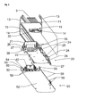
- FIG. 1 shows a light 1 with housing, comprising a profile 10 having an H-type cross section.
- the profile has a base leg 11, and two pairs of free legs 13, 14 extending from the base leg 11.
- the legs 13 and the base leg 11 provide a cable duct 17 that may be closed by a cover 16.
- the space between the legs 11, 14 forms a compartment 18 for a controller 20 and a lighting module 50.
- a cable 5 for providing the controller with power and preferably as well with data via some data line.
- the cable 5 is connected to a first connector 30, extending through the base leg 11.
- the first connector 30 is connected with a second connector 35, which is hidden in Fig.1 (cf. Fig. 2 ).
- the second connector 35 is integrated in the casing of the controller 20.
- the casing has an upper and a lower half shell 21, 22. Between the half shells 21, 22 are electronic components (not shown).
- the controller 20 is positioned in the compartment 18 and attached to the profile 10 by flexible levers 25 of first support structures.
- the levers 25 engage with rim like protrusions 15 extending from the legs 14 into the compartment 18, as will be explained in more detail below. Attached to the controller 20 is a light module 50.
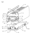
- Fig. 2 shows an exploded isometric sectional view of the light of Fig. 1 .
- the controller 20 has a third connector 36 mating with fourth connector 40 of the light module 50.
- the light module 50 and the controller 20 may be attached to each other by second support structures.
- the second support structures have latches 26, extending from the casing of the controller. At the distal ends of the latches 26 are catches 27, which may engage into recess members 55 of the light module 50 and thereby attach the light module 50 to the controller 20.
- the light module 50 comprises a transmissive base 51.
- the base 51 has at least one recess 57 defining a light exit window 52 and at least one rest 52 for a printed circuit board 54.
- the rest 52 defines the position of the printed circuit 54 board relative to the light exit window 52.
- the printed circuit board 54 may cover the recess 57 and support light sources like LEDs 56.
- the printed circuit board 54 and the base 51 may be attached to each other by a connection frame 60.
- the light module 50 in particular the base 51 of the light module, may have protrusions 59 as interlocking members 59.
- Each interlocking member 59 may block the levers 25 of the first support structure. This means, attaching the light module 50 to the controller interlocks the controller with the cable duct 17.
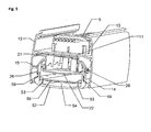
- Fig. 3 shows a partially mounted, section of the light.
- the controller 20 is already attached with the profile 10 of the cable duct 17.
- the second connector 35 engages with the first connector 30 and the first support structure (hidden, cf. Fig. 2 ) attaches the controller and the cable duct 17.
- the light module 50 is prepared for being attached and simultaneously connected to the controller 20. Depicted is a printed circuit board 54, covering the recess just above the light exit window 52 of the base 51.
- the base 51 has protrusion like interlocking members 59 and recess members 55, the latter being part of the second support structure.
- the third connector 36 and the fourth connector 40 cannot be seen in Fig.3 , as they are longitudinally displaced relative to the first and second connectors, as can be seen in Fig. 4 .
- Fig. 4 shows a further section of partially mounted light 1 after attachment of the controller 20.
- the light module 50 is prepared for attachment to the controller 20.
- the light module has a base 51 with a recess defining a light exit window 52. At least the narrow sides of the recess form a step which is a rest 53 for the printed circuit board 54.
- the printed circuit board 54 may have a metal layer for dissipating heat produced by the light sources.
- the printed circuit board may have a through hole, through which a fourth connector 40 extends.
- the fourth connector is electrically connected with the printed circuit board at its exit window facing side.
- the fourth connector 40 is positioned just opposite of the third connector 36, for mating it simultaneously with attaching the light module 50 to the controller 20.
- the light 1 has second support structures.
- the second support structures comprise latches 26, each having at their distal ends a catch 27 for engaging with complementary recess members 55.
- the recess members 55 are in the shown example protrusions extending from the light module 50, each having two recesses each for engagement of a catch 27.
- Fig. 5 shows detail of a section of the light after attachment of the light module 50 to the controller 20.
- the light module closes the compartment 18, however, between the light module and the legs 14 remains a small ventilation gap.
- the light module 50 and the controller 20 are thus vented and thereby cooled.
- the first support structure attaches the controller to the cable duct 17, in particular to the legs 14 of the profile 10.
- the first support structure comprises levers 25, which are flexibly connected to the controller 20, in the depicted example to the upper half 21 of the casing of the controller 20.
- the levers 25 each have a nose 24 facing away from the casing.
- the protrusions 15 of the legs 14 slide over the bridge of the nose 24 thereby pivoting the lever 25 towards the controller 20 until it reaches its final position, i.e., the depicted position. Now the levers 25 pivot towards the legs 14 and the lower side of the nose 24 engages with the protrusion 15. Subsequently the light module is attached to the controller 20.
- the light module has interlocking members 59, each being positioned as a block at the controller 20 facing side of the levers 25, thereby preventing the levers 25 from pivoting and thus preventing the noses 24 from releasing the protrusion 15, which would release the attachment of the controller 20 to the cable duct 17.
- the third and fourth connectors When attaching the light module 50 to the controller 20, the third and fourth connectors get mated. At the same time the catches 27 slide over the respective recess members 55 thereby pivoting the latches 26 until each of the catches 27 enters the recess of the respective recess member 55. Now the third and fourth connectors 36, 40 are connected and the light module 50 is attached to the controller. The light is completely assembled. No tools or specific skills, like those of certified electrician are necessary. For mounting the light, one simply has to "click" the controller to the cable duct 17 and the light module to the controller. In case of failure of the light module 50 or the controller 20, the respective support structures can be released one after the other and the components can be replaced easily.
- the latches 27 are pivoted for releasing the engagement of the clatches 27 with the recess members 55. Subsequently the light module can be pulled away from the controller 20, thereby decoupling the third and fourth connectors 36, 40.
- the path, required to pull the light module away from the controller to decouple the third and fourth connectors 36, 40 is preferably shorter than the section of the interlocking members 59, that engage with the first support structures. Thereby, it can be ensured that the interlocking of the first support structure, i.e., of the attachment of the cable duct 17 and controller 20 cannot be released until unmounting of the light module 50 is accomplished.
- the light can be further simplified, if the cable 5 has connectors at both of its ends, permitting to form rows of lights, by simply aligning the profiles 10 to form a common cable duct 17 and to connect the cables 5 accordingly. Subsequently the controllers 20 and the light modules 50 can be attached as described above.
- the controller may comprise a power supply for the light sources.
- the power line may be a one-phase or multi-phase AC power signal or a DC signal not suited to directly drive the at least one light source, e.g. one or multiple LEDs.
- the controller may convert the power provided by the power line into a power signal for the at least one light source.
- the controller may as well monitor variables like temperatures of the light sources and/or the printed circuit board, power on time of the light sources light intensity or the like and control the power provided to the light sources a function of at least one of the variables.
- the controller 20 is connected by some data bus to a main controller.
- the data bus permits the main controller to exchange data, e.g. values of the above listes variables with the controller and/or to send instructions like "power on light at xx%", "power off light”.
Abstract
Description
- The invention relates to a modular LED-light comprising a housing for a controller and a light module according to the preamble of
claim 1. -
US 2006/0262545 discloses a modular LED light. The LED light has a housing with a compartment for insertion of a controller. The controller is connected by wirings to a power line and to a data bus, e.g. Ethernet via RJ45 jacks. The controller is connected to a LED module by an output wiring. The output wiring may end in a socket for connector of a LED module. The socket is attached to a base, the latter being supported by the housing. For mounting the LED light, the housing is inserted into an aperture in a ceiling and fixed to the ceiling. Subsequently the wiring is connected to the power line, a control input wire and inserted via an opening of the housing into the compartment. When the controller reaches its final position, it is attached to the housing by a clamping element. - The invention is based on the observation that LED-lights for wall or ceilings often have a modular design. However, they are complicated to mount and in most cases mounting require a certified electrician for connecting the wires.
- The problem to be solved by the invention is to provide an easy to mount modular LED-light that is in particular suited for being arranged in a row with other lights, to form a "light strip", i.e., a row of lights.
- Solutions of the problem are described in the independent claims. The dependent claims relate to further improvements of the invention.
- The light comprises at least housing for a light module and a controller. The controller preferably has a casing and is electrically connected to a power line and to the light module. The housing preferably comprises a cable duct for housing the at least one power line. The cable duct may comprise at least a first connector being attached to the cable duct. The controller may comprise at least a second connector and preferably as well third connector. The second connector is complementary to the first connector. The cable duct and/or the controller preferably comprise a first support structure for attaching the cable duct with the controller. The first support structure attaches the cable duct to the controller when the first connector and the second connector reach their final plugged position. This permits to electrically connect and to mechanically attach the controller and the cable duct simultaneously.
- Preferably, the second connector can be plugged into the first connector from the outside of the cable duct, i.e., the first connector can be accessed without opening the cable duct. Thereby, the power line and the "user interface side" of the first connector are separated.
- The light may further comprise a controller with at least a casing, a second connector and a third connector, wherein the second connector is complementary to the first connector and wherein the second connector and the third connector are each pluggable from the outside of the cable duct. This permits to directly connect the first and second connectors. At least one of the second and third connectors is preferably fixed to the casing of the controller. The second and/or third connectors may be integrated in the casing. Their pins and/or female counterparts may be mounted directly to a circuit board of the controller. The light module may comprise a fourth connector. If the latter is complementary to the third connector and pluggable from the outside of the casing, the light module can be connected to the controller by simply plugging the third and fourth connector.
- Preferably, the cable duct and/or the controller comprise(s) a first support structure for attaching the cable duct with the controller, wherein the first support structure attaches the cable duct with the controller, when the first connector and the second connector reach their final positions. Thus, when the first and second connectors are plugged, the controller is automatically attached to the cable duct. The first support structure may be integrated in the first and/or second connectors. Alternatively the first support structure is separate, but preferably the cable duct and the controller are attached to each other at the same time the first and second connectors are connected to each other. The first support structure may interlock the connection of the first and second connectors.
- Preferably, the light module and/or the controller comprise a second support structure for attaching the light module with the controller, wherein the second support structure attaches the light module with the controller, when the third connector and the fourth connector reach their final plugged positions. This permits to simply and safely attach and connect the light module to the cable duct and/or the controller, respectively.
- The first support structure and/or the second support structure may be integrated at least in part in the first connector and the second connector and/or in the third connector and the fourth connector, respectively.
- The extension of the cable duct defines a longitudinal direction and transversal direction. Preferably the second connector and the third connector are displaced against each other in the longitudinal direction and/or the transversal direction. This permits to design a controller with a reduced height. A controller may be connected to and/or attached with two or more light modules. Accordingly the controller may have two or more third connectors.
- Preferably the cable duct comprises at least a profile, with at least a base segment and two legs extending from the base segment, wherein the base segment and the two legs form a compartment for at least the controller and/or the light module. The controller may be inserted easily into the compartment, the first and second connectors may be connected simultaneously and the support structure may attach the cable duct with the controller simultaneously. Thus, mounting of the controller is extremely easy, as it is sufficient to insert it into the compartment. The two legs are preferably part of the support structure and may be configured as guides for the controller, guiding it to its final attached position when inserting the controller into the compartment. For example, the cable duct may comprise a profile with an H-type cross section. The horizontal bar of the H type profile forms the base segment. The two downwardly extending legs may form said legs. These legs may define the compartment for the controller. The two upwardly extending legs may form a cable duct for housing, e.g., a power line or other cables. A cover may close the cable duct.
- For example, may the two legs each have at least a first attachment member and the controller may have at least a second attachment member. The first and second attachment members may engage when the controller reaches its final position in the compartment and thereby attach the cable duct with the controller.
- The light module may cover the compartment for the controller, when plugged to the controller. Thus, the light appears to be fully integrated in the cable duct.
- Preferably the light module has at least an interlocking member, wherein the interlocking member blocks at least one of the first or second attachment members from releasing the engagement. For example may the interlocking member be a protrusion engaging in a recess of the controller, thereby blocking at least one of the first or second attachment members from being pivoted out of the engagement with the respective second and/or first attachment member.
- For example, the light module may comprise a base with at least a light exit window. The base may comprise at least one recess defining the light exit window, and at least one rest defining the position of at least one printed circuit board relative to the light exit window. The printed circuit board preferably covers the recess. The printed circuit board and the cover may be attached to each other by a connection frame. This kind of attachment reduces strain on the printed circuit board and the base due to heat of operating LEDs or other light sources. The light module comprises at least one light source, e.g., one or more LEDs. The light sources are preferably in a box like section being confined by the base and the printed circuit board.
- In the following the invention will be described by way of example, without limitation of the general inventive concept, on examples of embodiment with reference to the drawings.
-
Figure 1 shows sectional view of a light. -
Figure 2 shows an exploded isometric sectional view of a light -
Figure 3 shows a sectional view of a partially mounted light. -
Figure 4 shows a sectional view of a partially mounted light. -
Figure 5 shows a sectional view of a light. - The sectional view in
Fig. 1 shows alight 1 with housing, comprising aprofile 10 having an H-type cross section. Thus, the profile has abase leg 11, and two pairs offree legs base leg 11. Thelegs 13 and thebase leg 11 provide acable duct 17 that may be closed by acover 16. The space between thelegs compartment 18 for acontroller 20 and alighting module 50. - In the
cable duct 17 is acable 5 for providing the controller with power and preferably as well with data via some data line. Thecable 5 is connected to afirst connector 30, extending through thebase leg 11. Thefirst connector 30 is connected with asecond connector 35, which is hidden inFig.1 (cf.Fig. 2 ). Thesecond connector 35 is integrated in the casing of thecontroller 20. The casing has an upper and alower half shell half shells controller 20 is positioned in thecompartment 18 and attached to theprofile 10 byflexible levers 25 of first support structures. Thelevers 25 engage with rim likeprotrusions 15 extending from thelegs 14 into thecompartment 18, as will be explained in more detail below. Attached to thecontroller 20 is alight module 50. -
Fig. 2 shows an exploded isometric sectional view of the light ofFig. 1 . As can be seen inFig.2 , thecontroller 20 has athird connector 36 mating withfourth connector 40 of thelight module 50. Thelight module 50 and thecontroller 20 may be attached to each other by second support structures. The second support structures havelatches 26, extending from the casing of the controller. At the distal ends of thelatches 26 arecatches 27, which may engage intorecess members 55 of thelight module 50 and thereby attach thelight module 50 to thecontroller 20. - The
light module 50 comprises atransmissive base 51. Thebase 51 has at least one recess 57 defining alight exit window 52 and at least onerest 52 for a printedcircuit board 54. Therest 52 defines the position of the printedcircuit 54 board relative to thelight exit window 52. The printedcircuit board 54 may cover the recess 57 and support light sources likeLEDs 56. The printedcircuit board 54 and the base 51 may be attached to each other by aconnection frame 60. - The
light module 50, in particular thebase 51 of the light module, may haveprotrusions 59 as interlockingmembers 59. Each interlockingmember 59 may block thelevers 25 of the first support structure. This means, attaching thelight module 50 to the controller interlocks the controller with thecable duct 17. -
Fig. 3 shows a partially mounted, section of the light. Thecontroller 20 is already attached with theprofile 10 of thecable duct 17. Thesecond connector 35 engages with thefirst connector 30 and the first support structure (hidden, cf.Fig. 2 ) attaches the controller and thecable duct 17. Thelight module 50 is prepared for being attached and simultaneously connected to thecontroller 20. Depicted is a printedcircuit board 54, covering the recess just above thelight exit window 52 of thebase 51. As can be best seen inFig. 3 , thebase 51 has protrusion like interlockingmembers 59 andrecess members 55, the latter being part of the second support structure. Thethird connector 36 and thefourth connector 40 cannot be seen inFig.3 , as they are longitudinally displaced relative to the first and second connectors, as can be seen inFig. 4 . -
Fig. 4 shows a further section of partially mountedlight 1 after attachment of thecontroller 20. Thelight module 50 is prepared for attachment to thecontroller 20. As can be seen, the light module has a base 51 with a recess defining alight exit window 52. At least the narrow sides of the recess form a step which is a rest 53 for the printedcircuit board 54. The printedcircuit board 54 may have a metal layer for dissipating heat produced by the light sources. As depicted, the printed circuit board may have a through hole, through which afourth connector 40 extends. Preferably, the fourth connector is electrically connected with the printed circuit board at its exit window facing side. Thefourth connector 40 is positioned just opposite of thethird connector 36, for mating it simultaneously with attaching thelight module 50 to thecontroller 20. For attaching thelight module 50 with the controller, thelight 1 has second support structures. The second support structures compriselatches 26, each having at their distal ends acatch 27 for engaging withcomplementary recess members 55. Therecess members 55 are in the shown example protrusions extending from thelight module 50, each having two recesses each for engagement of acatch 27. -
Fig. 5 shows detail of a section of the light after attachment of thelight module 50 to thecontroller 20. The light module closes thecompartment 18, however, between the light module and thelegs 14 remains a small ventilation gap. Thelight module 50 and thecontroller 20 are thus vented and thereby cooled. As already explained above, the first support structure attaches the controller to thecable duct 17, in particular to thelegs 14 of theprofile 10. As can be seen here the first support structure compriseslevers 25, which are flexibly connected to thecontroller 20, in the depicted example to theupper half 21 of the casing of thecontroller 20. Thelevers 25 each have anose 24 facing away from the casing. When inserting thecontroller 20 into thecompartment 18, theprotrusions 15 of thelegs 14 slide over the bridge of thenose 24 thereby pivoting thelever 25 towards thecontroller 20 until it reaches its final position, i.e., the depicted position. Now thelevers 25 pivot towards thelegs 14 and the lower side of thenose 24 engages with theprotrusion 15. Subsequently the light module is attached to thecontroller 20. The light module has interlockingmembers 59, each being positioned as a block at thecontroller 20 facing side of thelevers 25, thereby preventing thelevers 25 from pivoting and thus preventing thenoses 24 from releasing theprotrusion 15, which would release the attachment of thecontroller 20 to thecable duct 17. - When attaching the
light module 50 to thecontroller 20, the third and fourth connectors get mated. At the same time thecatches 27 slide over therespective recess members 55 thereby pivoting thelatches 26 until each of thecatches 27 enters the recess of therespective recess member 55. Now the third andfourth connectors light module 50 is attached to the controller. The light is completely assembled. No tools or specific skills, like those of certified electrician are necessary. For mounting the light, one simply has to "click" the controller to thecable duct 17 and the light module to the controller. In case of failure of thelight module 50 or thecontroller 20, the respective support structures can be released one after the other and the components can be replaced easily. For releasing thelight module 50 thelatches 27 are pivoted for releasing the engagement of theclatches 27 with therecess members 55. Subsequently the light module can be pulled away from thecontroller 20, thereby decoupling the third andfourth connectors fourth connectors members 59, that engage with the first support structures. Thereby, it can be ensured that the interlocking of the first support structure, i.e., of the attachment of thecable duct 17 andcontroller 20 cannot be released until unmounting of thelight module 50 is accomplished. - Mounting of the light can be further simplified, if the
cable 5 has connectors at both of its ends, permitting to form rows of lights, by simply aligning theprofiles 10 to form acommon cable duct 17 and to connect thecables 5 accordingly. Subsequently thecontrollers 20 and thelight modules 50 can be attached as described above. - It is to be understood, that the controller may comprise a power supply for the light sources. The power line may be a one-phase or multi-phase AC power signal or a DC signal not suited to directly drive the at least one light source, e.g. one or multiple LEDs. The controller may convert the power provided by the power line into a power signal for the at least one light source.
- The controller may as well monitor variables like temperatures of the light sources and/or the printed circuit board, power on time of the light sources light intensity or the like and control the power provided to the light sources a function of at least one of the variables. Preferably the
controller 20 is connected by some data bus to a main controller. The data bus permits the main controller to exchange data, e.g. values of the above listes variables with the controller and/or to send instructions like "power on light at xx%", "power off light". -
- 1
- light
- 5
- cable / ribbon cable
- 10
- profile
- 11
- base leg
- 13
- free leg
- 14
- free leg
- 15
- protrusion of first support structure
- 16
- cable duct cover
- 17
- cable duct
- 18
- compartment
- 20
- controller
- 21
- upper half shell of casing
- 22
- lower half shell of casing
- 24
- nose
- 25
- lever
- 26
- latch
- 27
- catch
- 30
- first connector
- 35
- second connector
- 36
- third connector
- 40
- fourth connector
- 50
- light module
- 51
- base / lamp cover
- 52
- light exit window/recess
- 53
- rest
- 54
- printed circuit board
- 55
- recess member of second support structure
- 56
- LED / light source
- 58
- gap
- 59
- interlocking member / protrusion
- 60
- connection frame
Claims (11)
- A light (1) comprising at least a housing (10) for a light module (50) and a controller (20) with a casing, the controller (20) being electrically connected to a power line (5) and to the light module (50) characterized in that- the housing comprises a cable duct (17) for housing the at least one power line (5), the cable duct (17) comprising at least a first connector (30) being attached to the cable duct,- the controller (20) comprises at least a second connector (35) and a third connector (36), wherein the second connector (35) is complementary to the first connector (30),- the cable duct (17) and/or the controller (20) comprise a first support structure (15, 25) for attaching the cable duct (17) with the controller (20), wherein the first support structure (15, 25) attaches the cable duct (17) to the controller (20), when the first connector (35) and the second connector (36) get plugged.
- The light of claim 1
characterized in that
the light module (50) comprises at least a fourth connector (40) and in that the light module (50) and/or the controller (20) comprise a second support structure for attaching the light module (50) with the controller (20), wherein the second support structure attaches the light module (50) with the controller (20), when the third connector (36) and the fourth connector (40) get plugged. - The light (1) of claim 1 or 2,
characterized in that
the first support structure and/or the second support structure are integrated at least in part in the first connector (30) and the second connector (35) and/or in the third connector (36) and the fourth connector (40). - The light (1) of one of the preceding claims
characterized in that
the extension of the cable duct (17) defines a longitudinal direction and a transversal direction and in that the second connector (30) and the third connector (35) are displaced against each other in the longitudinal direction and/or the transversal direction. - The light (1) of one of the preceding claims,
characterized in that
the housing comprises at least a profile (10), with a base leg (11)and a pair of legs (14) extending from the base leg (11), wherein the base leg 11 and the pair of legs (14) form a compartment (18) for at least the controller (20) and/or the light module (50). - The light (1) of claim 5,
characterized in that
light module (50) covers the compartment (18). - The light (1) module of one of the preceding claims characterized in that
the legs (14) each have at least a first attachment member (15) and the controller (20) has at least a second attachment member (25), wherein the first and second attachment members (15, 25) engage and thereby attach the cable duct (17) with the controller (20). - The light of one of the preceding claims,
characterized in that
the light module (50) has at least one interlocking member (59), wherein the interlocking member (59) blocks at least one of the first or second attachment members (15, 25) from releasing the engagement. - The light of one of the preceding claims
characterized in that
at least one of the second and third connectors (30,35) is fixed to the casing of the controller (20). - The light of one of the preceding claims,
characterized in that
the light module (50) comprises a base (51), the base having a recess defining an light exit window (52), and at least one rest (53) defining the position of a printed circuit board (54) relative to the light exit window (52), wherein the printed circuit board (54) covers the recess, and wherein the printed circuit board (54) and the base (51) are attached to each other. - A kit for a light, comprising at least:- a housing (10) for a light module (50) and a controller (20), the housing (10) comprising at least a cable duct (17) for housing at least one power line (5), wherein the cable duct (17) comprises at least a first connector (30) being attached to the cable duct (17)- the controller (20) comprising at least a second connector (35) for mating the first connector (30) thereby being electrically connected to the power line (5)- the light module (50) for being electrically connected to the controller (20).
Priority Applications (13)
| Application Number | Priority Date | Filing Date | Title |
|---|---|---|---|
| DK12164193.0T DK2650607T3 (en) | 2012-04-13 | 2012-04-13 | Modular LED lamp |
| ES12164193.0T ES2507740T3 (en) | 2012-04-13 | 2012-04-13 | LED modular light |
| PL12164193T PL2650607T3 (en) | 2012-04-13 | 2012-04-13 | Modular LED light |
| EP12164193.0A EP2650607B1 (en) | 2012-04-13 | 2012-04-13 | Modular LED light |
| EP12178841.8A EP2650610B1 (en) | 2012-04-13 | 2012-08-01 | Sealed LED light module |
| PL12178841T PL2650610T3 (en) | 2012-04-13 | 2012-08-01 | Sealed LED light module |
| DK12178841.8T DK2650610T3 (en) | 2012-04-13 | 2012-08-01 | Sealed LED light module |
| ES12178841.8T ES2567048T3 (en) | 2012-04-13 | 2012-08-01 | LED sealed light module |
| JP2015504974A JP5784262B2 (en) | 2012-04-13 | 2013-04-12 | Modular LED light source |
| PCT/EP2013/057734 WO2013153217A1 (en) | 2012-04-13 | 2013-04-12 | Modular led light |
| JP2015524738A JP5940217B2 (en) | 2012-04-13 | 2013-07-26 | Sealed LED light source module |
| US14/512,836 US9188324B2 (en) | 2012-04-13 | 2014-10-13 | Modular LED light |
| US14/610,634 US10139098B2 (en) | 2012-04-13 | 2015-01-30 | Sealed LED light module |
Applications Claiming Priority (1)
| Application Number | Priority Date | Filing Date | Title |
|---|---|---|---|
| EP12164193.0A EP2650607B1 (en) | 2012-04-13 | 2012-04-13 | Modular LED light |
Publications (2)
| Publication Number | Publication Date |
|---|---|
| EP2650607A1 true EP2650607A1 (en) | 2013-10-16 |
| EP2650607B1 EP2650607B1 (en) | 2014-07-23 |
Family
ID=46603724
Family Applications (2)
| Application Number | Title | Priority Date | Filing Date |
|---|---|---|---|
| EP12164193.0A Revoked EP2650607B1 (en) | 2012-04-13 | 2012-04-13 | Modular LED light |
| EP12178841.8A Active EP2650610B1 (en) | 2012-04-13 | 2012-08-01 | Sealed LED light module |
Family Applications After (1)
| Application Number | Title | Priority Date | Filing Date |
|---|---|---|---|
| EP12178841.8A Active EP2650610B1 (en) | 2012-04-13 | 2012-08-01 | Sealed LED light module |
Country Status (7)
| Country | Link |
|---|---|
| US (2) | US9188324B2 (en) |
| EP (2) | EP2650607B1 (en) |
| JP (2) | JP5784262B2 (en) |
| DK (2) | DK2650607T3 (en) |
| ES (2) | ES2507740T3 (en) |
| PL (2) | PL2650607T3 (en) |
| WO (1) | WO2013153217A1 (en) |
Cited By (16)
| Publication number | Priority date | Publication date | Assignee | Title |
|---|---|---|---|---|
| WO2014202666A1 (en) * | 2013-06-20 | 2014-12-24 | Zumtobel Lighting Gmbh | Lamp for use in a lighting strip system and lighting strip system |
| WO2015132225A1 (en) * | 2014-03-03 | 2015-09-11 | Zumtobel Lighting Gmbh | Light fixture comprising a carrier element and detachably securable lighting module |
| FR3023356A1 (en) * | 2014-07-03 | 2016-01-08 | Briand En | CABLE TRAY ASSEMBLY AND LIGHTING SYSTEM COMPRISING SAME |
| DE202014106102U1 (en) * | 2014-12-17 | 2016-03-18 | Zumtobel Lighting Gmbh | Equipment carrier and illuminant carrier for a continuous line luminaire |
| DE202014106111U1 (en) * | 2014-12-17 | 2016-03-18 | Zumtobel Lighting Gmbh | Equipment carrier for a continuous line luminaire |
| WO2016097321A1 (en) * | 2014-12-18 | 2016-06-23 | Itz Innovations- Und Technologiezentrum Gmbh | Modular illumination device |
| EP3067617A1 (en) * | 2015-03-11 | 2016-09-14 | LEDeXCHANGE GmbH | Method for mounting a luminaire |
| EP3217088A2 (en) | 2016-03-10 | 2017-09-13 | ITZ Innovations- und Technologiezentrum GmbH | Modular lighting device in the form of a light strip and a connection system for same |
| DE102016117157B3 (en) * | 2016-09-13 | 2018-02-01 | Insta Gmbh | light assembly |
| EP3336420A1 (en) * | 2016-12-15 | 2018-06-20 | H4X e.U. | Lighting system |
| EP3361141A1 (en) * | 2017-02-10 | 2018-08-15 | BEGA Gantenbrink-Leuchten KG | Linear luminaire and method for its assembly |
| WO2018210642A1 (en) * | 2017-05-16 | 2018-11-22 | Schreder S.A. | Tool-less light fixture |
| US10139098B2 (en) | 2012-04-13 | 2018-11-27 | Lunux Gmbh | Sealed LED light module |
| DE202018100522U1 (en) * | 2018-01-31 | 2019-05-03 | Zumtobel Lighting Gmbh | Lighting system |
| IT201800007005A1 (en) * | 2018-07-06 | 2020-01-06 | Assembly system for led lighting device | |
| EP3680551B1 (en) * | 2019-01-14 | 2022-03-09 | Zumtobel Lighting GmbH | Lighting module for a light strip system |
Families Citing this family (13)
| Publication number | Priority date | Publication date | Assignee | Title |
|---|---|---|---|---|
| DE102013201203A1 (en) * | 2013-01-25 | 2014-07-31 | Zumtobel Lighting Gmbh | Lighting system |
| US9890575B2 (en) * | 2013-12-09 | 2018-02-13 | Viking Access Systems, Llc | Movable barrier operator with removable power supply module |
| DE112015002678T5 (en) * | 2014-06-06 | 2017-02-23 | Opple Lighting Co., Ltd. | LED lighting device |
| US20160169462A1 (en) * | 2014-12-13 | 2016-06-16 | James Bradford Hawkins | Track system for light emitting diode (led) fixture |
| JP6664152B2 (en) * | 2015-04-28 | 2020-03-13 | 三菱電機株式会社 | Lighting equipment |
| DE102015107213A1 (en) | 2015-05-08 | 2016-11-10 | Trilux Gmbh & Co. Kg | LED lighting module |
| DE102015112838A1 (en) * | 2015-08-05 | 2017-02-09 | Selux Ag | Lighting arrangement for busbars |
| DE202015105855U1 (en) * | 2015-11-04 | 2017-02-08 | Zumtobel Lighting Gmbh | Oblong light band element |
| DE102018106040A1 (en) * | 2018-03-15 | 2019-09-19 | Occhio GmbH | Lighting device and method for its manufacture and assembly |
| CN110985904A (en) * | 2020-01-02 | 2020-04-10 | 东莞市泰亮半导体照明有限公司 | Modular lamp |
| CN111129813A (en) * | 2020-01-02 | 2020-05-08 | 东莞市泰亮半导体照明有限公司 | Lamp connecting piece |
| JP7003177B2 (en) * | 2020-04-14 | 2022-02-04 | 三菱電機株式会社 | lighting equipment |
| WO2024056812A1 (en) * | 2022-09-16 | 2024-03-21 | Signify Holding B.V. | Luminaire and method of manufacturing a luminaire |
Citations (3)
| Publication number | Priority date | Publication date | Assignee | Title |
|---|---|---|---|---|
| US20040184264A1 (en) * | 2003-03-18 | 2004-09-23 | Elam Thomas E. | Modular ambient lighting system |
| US20060262545A1 (en) | 2005-05-23 | 2006-11-23 | Color Kinetics Incorporated | Led-based light-generating modules for socket engagement, and methods of assembling, installing and removing same |
| US20090268435A1 (en) * | 2008-04-29 | 2009-10-29 | Man-D-Tec | Downward Illumination Assembly |
Family Cites Families (34)
| Publication number | Priority date | Publication date | Assignee | Title |
|---|---|---|---|---|
| DE1589363A1 (en) | 1967-02-20 | 1970-09-10 | Trilux Lenze Gmbh & Co Kg | Hospital room wall light |
| US5632551A (en) * | 1994-07-18 | 1997-05-27 | Grote Industries, Inc. | LED vehicle lamp assembly |
| DE10025646A1 (en) | 2000-05-24 | 2001-11-29 | Zumtobel Staff Gmbh | Track system |
| EP1182396B1 (en) | 2000-08-22 | 2009-10-14 | Koninklijke Philips Electronics N.V. | Lamp based on LEDs' light emission |
| DE10106961A1 (en) * | 2001-02-15 | 2002-08-29 | Happich Fahrzeug & Ind Teile | Bleuchtungseinrichtung |
| US20020137374A1 (en) | 2001-03-21 | 2002-09-26 | O'rourke John | Modular ballast housing for a track lighting fixture |
| DE10145499A1 (en) | 2001-09-14 | 2003-04-03 | Zumtobel Staff Gmbh & Co Kg | Lighting channel system |
| EP1478884B1 (en) * | 2002-02-06 | 2011-06-22 | odelo GmbH | Center high mounted stop lamp including leds and tir lens |
| DE10241941B4 (en) | 2002-09-10 | 2015-07-02 | Zumtobel Lighting Gmbh | Lighting system, adaptation element and luminaire with it |
| US7429186B2 (en) | 2004-04-06 | 2008-09-30 | Lumination Llc | Flexible high-power LED lighting system |
| US8061865B2 (en) | 2005-05-23 | 2011-11-22 | Philips Solid-State Lighting Solutions, Inc. | Methods and apparatus for providing lighting via a grid system of a suspended ceiling |
| SM200600005B (en) | 2006-02-15 | 2007-08-22 | Idealed.It S R L | High power LED light unit, as well as lighting apparatus comprising this unit |
| DE202006003729U1 (en) | 2006-03-07 | 2006-06-01 | Trilux-Lenze Gmbh + Co. Kg | Multifunctional channel |
| JP4825160B2 (en) | 2007-04-06 | 2011-11-30 | コイズミ照明株式会社 | LED lighting fixtures |
| JP4881807B2 (en) | 2007-07-27 | 2012-02-22 | 日立オートモティブシステムズ株式会社 | Hydraulic brake device |
| US8491148B2 (en) * | 2007-10-27 | 2013-07-23 | Osram Sylvania Inc. | Chambered waterproof lamp assembly having a transparent cover switch activator |
| PT2086065E (en) | 2008-01-31 | 2010-06-22 | Bticino Spa | Clasping device for the engagement with a suspended electrical duct |
| PT2088368E (en) | 2008-02-11 | 2010-07-05 | Bticino Spa | Lighting apparatus for installation on a suspended electrical duct |
| CN101603677B (en) * | 2008-06-13 | 2012-03-14 | 富准精密工业(深圳)有限公司 | LED lamp fitting |
| DE102008036474A1 (en) | 2008-08-05 | 2010-02-11 | Zumtobel Lighting Gmbh | Lighting system |
| JP2008305807A (en) * | 2008-08-22 | 2008-12-18 | Takagi Kogyo Kk | Underwater lighting body |
| JP5279133B2 (en) * | 2009-01-13 | 2013-09-04 | 株式会社エンプラス | Light emitting device and lighting device |
| CN101886753A (en) * | 2009-05-11 | 2010-11-17 | 富准精密工业(深圳)有限公司 | Light-emitting diode lamp |
| CN201448812U (en) * | 2009-08-08 | 2010-05-05 | 木林森电子有限公司 | Fan light source |
| EP2317205A1 (en) * | 2009-10-27 | 2011-05-04 | Liang Meng Plastic Share Co. Ltd. | Housing of LED light source comprising electrical connector |
| US8235549B2 (en) * | 2009-12-09 | 2012-08-07 | Tyco Electronics Corporation | Solid state lighting assembly |
| JPWO2011122518A1 (en) | 2010-03-30 | 2013-07-08 | 東芝ライテック株式会社 | Tubular lamp and luminaire |
| DE102010021113A1 (en) | 2010-05-20 | 2011-11-24 | Hella Kgaa Hueck & Co. | lighting system |
| US8851703B2 (en) * | 2010-08-30 | 2014-10-07 | Michael A. Blackstone | Cooperating electrical ballast and socket |
| CN102434813B (en) * | 2010-09-29 | 2015-08-12 | 欧司朗股份有限公司 | Light emitting module and there is the back lighting lamp string of this light emitting module |
| DE102010042264C5 (en) | 2010-10-11 | 2016-04-07 | Trilux Gmbh & Co. Kg | lamp |
| US8419217B2 (en) * | 2011-01-21 | 2013-04-16 | Hergy Lighting Technology Corp. | LED lamp |
| JP5799217B2 (en) | 2011-02-28 | 2015-10-21 | パナソニックIpマネジメント株式会社 | LED unit and lighting apparatus using the same |
| EP2650607B1 (en) | 2012-04-13 | 2014-07-23 | Hella KGaA Hueck & Co | Modular LED light |
-
2012
- 2012-04-13 EP EP12164193.0A patent/EP2650607B1/en not_active Revoked
- 2012-04-13 ES ES12164193.0T patent/ES2507740T3/en active Active
- 2012-04-13 PL PL12164193T patent/PL2650607T3/en unknown
- 2012-04-13 DK DK12164193.0T patent/DK2650607T3/en active
- 2012-08-01 DK DK12178841.8T patent/DK2650610T3/en active
- 2012-08-01 PL PL12178841T patent/PL2650610T3/en unknown
- 2012-08-01 ES ES12178841.8T patent/ES2567048T3/en active Active
- 2012-08-01 EP EP12178841.8A patent/EP2650610B1/en active Active
-
2013
- 2013-04-12 JP JP2015504974A patent/JP5784262B2/en not_active Expired - Fee Related
- 2013-04-12 WO PCT/EP2013/057734 patent/WO2013153217A1/en active Application Filing
- 2013-07-26 JP JP2015524738A patent/JP5940217B2/en not_active Expired - Fee Related
-
2014
- 2014-10-13 US US14/512,836 patent/US9188324B2/en not_active Expired - Fee Related
-
2015
- 2015-01-30 US US14/610,634 patent/US10139098B2/en not_active Expired - Fee Related
Patent Citations (3)
| Publication number | Priority date | Publication date | Assignee | Title |
|---|---|---|---|---|
| US20040184264A1 (en) * | 2003-03-18 | 2004-09-23 | Elam Thomas E. | Modular ambient lighting system |
| US20060262545A1 (en) | 2005-05-23 | 2006-11-23 | Color Kinetics Incorporated | Led-based light-generating modules for socket engagement, and methods of assembling, installing and removing same |
| US20090268435A1 (en) * | 2008-04-29 | 2009-10-29 | Man-D-Tec | Downward Illumination Assembly |
Cited By (29)
| Publication number | Priority date | Publication date | Assignee | Title |
|---|---|---|---|---|
| US10139098B2 (en) | 2012-04-13 | 2018-11-27 | Lunux Gmbh | Sealed LED light module |
| WO2014202666A1 (en) * | 2013-06-20 | 2014-12-24 | Zumtobel Lighting Gmbh | Lamp for use in a lighting strip system and lighting strip system |
| US9976712B2 (en) | 2013-06-20 | 2018-05-22 | Zumtobel Lighting Gmbh | Lamp for use in a lighting strip system and lighting strip system |
| US9951913B2 (en) | 2014-03-03 | 2018-04-24 | Zumtobel Lighting Gmbh | Light fixture comprising a carrier element and detachably securable lighting module |
| WO2015132225A1 (en) * | 2014-03-03 | 2015-09-11 | Zumtobel Lighting Gmbh | Light fixture comprising a carrier element and detachably securable lighting module |
| FR3023356A1 (en) * | 2014-07-03 | 2016-01-08 | Briand En | CABLE TRAY ASSEMBLY AND LIGHTING SYSTEM COMPRISING SAME |
| DE202014106102U1 (en) * | 2014-12-17 | 2016-03-18 | Zumtobel Lighting Gmbh | Equipment carrier and illuminant carrier for a continuous line luminaire |
| DE202014106111U1 (en) * | 2014-12-17 | 2016-03-18 | Zumtobel Lighting Gmbh | Equipment carrier for a continuous line luminaire |
| WO2016096708A1 (en) * | 2014-12-17 | 2016-06-23 | Zumtobel Lighting Gmbh | Device carrier for a strip-lighting luminaire |
| EP3235072B1 (en) * | 2014-12-17 | 2020-02-05 | Zumtobel Lighting GmbH | A device carrier and an illuminant carrier for a light strip luminaire |
| US10302288B2 (en) | 2014-12-17 | 2019-05-28 | Zumtobel Lighting Gmbh | Device carrier for a strip-lighting luminaire |
| AT15310U1 (en) * | 2014-12-17 | 2017-05-15 | Zumtobel Lighting Gmbh | Equipment carrier for a continuous line luminaire |
| DE102014118980A1 (en) | 2014-12-18 | 2016-06-23 | Itz Innovations- Und Technologiezentrum Gmbh | Modular lighting device |
| WO2016097321A1 (en) * | 2014-12-18 | 2016-06-23 | Itz Innovations- Und Technologiezentrum Gmbh | Modular illumination device |
| EP3067617A1 (en) * | 2015-03-11 | 2016-09-14 | LEDeXCHANGE GmbH | Method for mounting a luminaire |
| DE102016104355A1 (en) | 2016-03-10 | 2017-09-14 | Itz Innovations- Und Technologiezentrum Gmbh | Modular lighting device in the form of a light band and connection system therefor |
| EP3217088A2 (en) | 2016-03-10 | 2017-09-13 | ITZ Innovations- und Technologiezentrum GmbH | Modular lighting device in the form of a light strip and a connection system for same |
| DE102016117157B3 (en) * | 2016-09-13 | 2018-02-01 | Insta Gmbh | light assembly |
| EP3336420A1 (en) * | 2016-12-15 | 2018-06-20 | H4X e.U. | Lighting system |
| US10323837B2 (en) | 2016-12-15 | 2019-06-18 | H4X E.U. | Lighting system |
| US10465867B2 (en) | 2017-02-10 | 2019-11-05 | Bega Gantenbrink-Leuchten Kg | Linear light and method for mounting of said light |
| EP3361141A1 (en) * | 2017-02-10 | 2018-08-15 | BEGA Gantenbrink-Leuchten KG | Linear luminaire and method for its assembly |
| WO2018210642A1 (en) * | 2017-05-16 | 2018-11-22 | Schreder S.A. | Tool-less light fixture |
| US20200116336A1 (en) * | 2017-05-16 | 2020-04-16 | Schreder S.A. | Tool-Less Light Fixture |
| US10876716B2 (en) | 2017-05-16 | 2020-12-29 | Schreder S.A. | Tool-less light fixture |
| DE202018100522U1 (en) * | 2018-01-31 | 2019-05-03 | Zumtobel Lighting Gmbh | Lighting system |
| US11098884B2 (en) | 2018-01-31 | 2021-08-24 | Zumtobel Lighting Gmbh | Strip lighting system |
| IT201800007005A1 (en) * | 2018-07-06 | 2020-01-06 | Assembly system for led lighting device | |
| EP3680551B1 (en) * | 2019-01-14 | 2022-03-09 | Zumtobel Lighting GmbH | Lighting module for a light strip system |
Also Published As
| Publication number | Publication date |
|---|---|
| EP2650610A3 (en) | 2013-11-06 |
| PL2650607T3 (en) | 2015-03-31 |
| EP2650607B1 (en) | 2014-07-23 |
| EP2650610B1 (en) | 2016-01-13 |
| US20150029731A1 (en) | 2015-01-29 |
| US20150138771A1 (en) | 2015-05-21 |
| JP5784262B2 (en) | 2015-09-24 |
| JP2015529944A (en) | 2015-10-08 |
| US9188324B2 (en) | 2015-11-17 |
| WO2013153217A1 (en) | 2013-10-17 |
| ES2567048T3 (en) | 2016-04-19 |
| PL2650610T3 (en) | 2016-06-30 |
| EP2650610A2 (en) | 2013-10-16 |
| ES2507740T3 (en) | 2014-10-15 |
| JP2015518634A (en) | 2015-07-02 |
| DK2650610T3 (en) | 2016-04-18 |
| JP5940217B2 (en) | 2016-06-29 |
| DK2650607T3 (en) | 2014-10-20 |
| US10139098B2 (en) | 2018-11-27 |
Similar Documents
| Publication | Publication Date | Title |
|---|---|---|
| EP2650607B1 (en) | Modular LED light | |
| EP2334155B1 (en) | Solid state lighting system | |
| US7268674B2 (en) | Remote dummy load | |
| CN108291710B (en) | Modular ceiling illuminator | |
| JP2000148214A (en) | Programmable logic controller and programmable logic controller module | |
| US10368458B2 (en) | Rail-mounted control system with improved mounting | |
| US11085621B2 (en) | Junction box-driver assembly for direct mount luminaires | |
| CN106523398B (en) | Ventilation equipment with lighting function | |
| CN1551437A (en) | Electric connection box and method of assembling same | |
| EP3744159B1 (en) | Electrical connector and electronic device | |
| JP4106560B2 (en) | Electronic equipment with electrical connector device | |
| JP4839859B2 (en) | Wiring duct | |
| JP2009224155A (en) | Lighting fixture | |
| JP2017050066A (en) | Luminaire | |
| US10962212B2 (en) | Recessed lighting fixture | |
| CN209842460U (en) | Extension type control device and host machine of extension type control device | |
| CN114375530A (en) | Connection device for a lighting device driver | |
| US8128424B2 (en) | Electrical receptacle assembly | |
| JP2016110873A (en) | Electrical connection device and lighting equipment using the same | |
| JP7464470B2 (en) | Electrical component wiring structure | |
| JP2019067628A (en) | Light source device, luminaire, lighting fixture, and lighting system | |
| CN213815347U (en) | LED display screen capable of being installed front and back and spliced screen | |
| JP7038318B2 (en) | LED modules, boards, lighting equipment, lighting fixtures and lighting systems | |
| JP7360088B2 (en) | guide light | |
| JP6964249B2 (en) | Lighting fixtures, lighting equipment, fixture bodies and lighting systems |
Legal Events
| Date | Code | Title | Description |
|---|---|---|---|
| PUAI | Public reference made under article 153(3) epc to a published international application that has entered the european phase |
Free format text: ORIGINAL CODE: 0009012 |
|
| 17P | Request for examination filed |
Effective date: 20130412 |
|
| AK | Designated contracting states |
Kind code of ref document: A1 Designated state(s): AL AT BE BG CH CY CZ DE DK EE ES FI FR GB GR HR HU IE IS IT LI LT LU LV MC MK MT NL NO PL PT RO RS SE SI SK SM TR |
|
| AX | Request for extension of the european patent |
Extension state: BA ME |
|
| REG | Reference to a national code |
Ref country code: DE Ref legal event code: R079 Ref document number: 602012002485 Country of ref document: DE Free format text: PREVIOUS MAIN CLASS: F21V0015010000 Ipc: F21V0023000000 |
|
| GRAP | Despatch of communication of intention to grant a patent |
Free format text: ORIGINAL CODE: EPIDOSNIGR1 |
|
| RIC1 | Information provided on ipc code assigned before grant |
Ipc: F21Y 101/02 20060101ALN20140116BHEP Ipc: F21K 99/00 20100101ALI20140116BHEP Ipc: F21V 15/01 20060101ALI20140116BHEP Ipc: F21V 23/00 20060101AFI20140116BHEP Ipc: F21V 31/00 20060101ALI20140116BHEP Ipc: F21V 19/00 20060101ALI20140116BHEP Ipc: F21V 3/00 20060101ALI20140116BHEP Ipc: F21V 23/06 20060101ALI20140116BHEP |
|
| INTG | Intention to grant announced |
Effective date: 20140129 |
|
| RBV | Designated contracting states (corrected) |
Designated state(s): AL AT BE BG CH CY CZ DE DK EE ES FI FR GB GR HR HU IE IS IT LI LT LU LV MC MK MT NL NO PL PT RO RS SE SI SK SM TR |
|
| GRAS | Grant fee paid |
Free format text: ORIGINAL CODE: EPIDOSNIGR3 |
|
| GRAA | (expected) grant |
Free format text: ORIGINAL CODE: 0009210 |
|
| AK | Designated contracting states |
Kind code of ref document: B1 Designated state(s): AL AT BE BG CH CY CZ DE DK EE ES FI FR GB GR HR HU IE IS IT LI LT LU LV MC MK MT NL NO PL PT RO RS SE SI SK SM TR |
|
| REG | Reference to a national code |
Ref country code: GB Ref legal event code: FG4D |
|
| REG | Reference to a national code |
Ref country code: CH Ref legal event code: EP |
|
| REG | Reference to a national code |
Ref country code: IE Ref legal event code: FG4D |
|
| REG | Reference to a national code |
Ref country code: AT Ref legal event code: REF Ref document number: 679085 Country of ref document: AT Kind code of ref document: T Effective date: 20140815 |
|
| REG | Reference to a national code |
Ref country code: DE Ref legal event code: R096 Ref document number: 602012002485 Country of ref document: DE Effective date: 20140904 |
|
| REG | Reference to a national code |
Ref country code: ES Ref legal event code: FG2A Ref document number: 2507740 Country of ref document: ES Kind code of ref document: T3 Effective date: 20141015 |
|
| REG | Reference to a national code |
Ref country code: DK Ref legal event code: T3 Effective date: 20141013 |
|
| REG | Reference to a national code |
Ref country code: NL Ref legal event code: T3 |
|
| REG | Reference to a national code |
Ref country code: AT Ref legal event code: MK05 Ref document number: 679085 Country of ref document: AT Kind code of ref document: T Effective date: 20140723 |
|
| REG | Reference to a national code |
Ref country code: LT Ref legal event code: MG4D |
|
| PG25 | Lapsed in a contracting state [announced via postgrant information from national office to epo] |
Ref country code: SE Free format text: LAPSE BECAUSE OF FAILURE TO SUBMIT A TRANSLATION OF THE DESCRIPTION OR TO PAY THE FEE WITHIN THE PRESCRIBED TIME-LIMIT Effective date: 20140723 Ref country code: LT Free format text: LAPSE BECAUSE OF FAILURE TO SUBMIT A TRANSLATION OF THE DESCRIPTION OR TO PAY THE FEE WITHIN THE PRESCRIBED TIME-LIMIT Effective date: 20140723 Ref country code: FI Free format text: LAPSE BECAUSE OF FAILURE TO SUBMIT A TRANSLATION OF THE DESCRIPTION OR TO PAY THE FEE WITHIN THE PRESCRIBED TIME-LIMIT Effective date: 20140723 Ref country code: NO Free format text: LAPSE BECAUSE OF FAILURE TO SUBMIT A TRANSLATION OF THE DESCRIPTION OR TO PAY THE FEE WITHIN THE PRESCRIBED TIME-LIMIT Effective date: 20141023 Ref country code: PT Free format text: LAPSE BECAUSE OF FAILURE TO SUBMIT A TRANSLATION OF THE DESCRIPTION OR TO PAY THE FEE WITHIN THE PRESCRIBED TIME-LIMIT Effective date: 20141124 Ref country code: GR Free format text: LAPSE BECAUSE OF FAILURE TO SUBMIT A TRANSLATION OF THE DESCRIPTION OR TO PAY THE FEE WITHIN THE PRESCRIBED TIME-LIMIT Effective date: 20141024 Ref country code: BG Free format text: LAPSE BECAUSE OF FAILURE TO SUBMIT A TRANSLATION OF THE DESCRIPTION OR TO PAY THE FEE WITHIN THE PRESCRIBED TIME-LIMIT Effective date: 20141023 |
|
| PG25 | Lapsed in a contracting state [announced via postgrant information from national office to epo] |
Ref country code: IS Free format text: LAPSE BECAUSE OF FAILURE TO SUBMIT A TRANSLATION OF THE DESCRIPTION OR TO PAY THE FEE WITHIN THE PRESCRIBED TIME-LIMIT Effective date: 20141123 Ref country code: RS Free format text: LAPSE BECAUSE OF FAILURE TO SUBMIT A TRANSLATION OF THE DESCRIPTION OR TO PAY THE FEE WITHIN THE PRESCRIBED TIME-LIMIT Effective date: 20140723 Ref country code: CY Free format text: LAPSE BECAUSE OF FAILURE TO SUBMIT A TRANSLATION OF THE DESCRIPTION OR TO PAY THE FEE WITHIN THE PRESCRIBED TIME-LIMIT Effective date: 20140723 Ref country code: AT Free format text: LAPSE BECAUSE OF FAILURE TO SUBMIT A TRANSLATION OF THE DESCRIPTION OR TO PAY THE FEE WITHIN THE PRESCRIBED TIME-LIMIT Effective date: 20140723 Ref country code: LV Free format text: LAPSE BECAUSE OF FAILURE TO SUBMIT A TRANSLATION OF THE DESCRIPTION OR TO PAY THE FEE WITHIN THE PRESCRIBED TIME-LIMIT Effective date: 20140723 Ref country code: HR Free format text: LAPSE BECAUSE OF FAILURE TO SUBMIT A TRANSLATION OF THE DESCRIPTION OR TO PAY THE FEE WITHIN THE PRESCRIBED TIME-LIMIT Effective date: 20140723 |
|
| REG | Reference to a national code |
Ref country code: PL Ref legal event code: T3 |
|
| REG | Reference to a national code |
Ref country code: DE Ref legal event code: R026 Ref document number: 602012002485 Country of ref document: DE |
|
| PG25 | Lapsed in a contracting state [announced via postgrant information from national office to epo] |
Ref country code: EE Free format text: LAPSE BECAUSE OF FAILURE TO SUBMIT A TRANSLATION OF THE DESCRIPTION OR TO PAY THE FEE WITHIN THE PRESCRIBED TIME-LIMIT Effective date: 20140723 Ref country code: CZ Free format text: LAPSE BECAUSE OF FAILURE TO SUBMIT A TRANSLATION OF THE DESCRIPTION OR TO PAY THE FEE WITHIN THE PRESCRIBED TIME-LIMIT Effective date: 20140723 Ref country code: RO Free format text: LAPSE BECAUSE OF FAILURE TO SUBMIT A TRANSLATION OF THE DESCRIPTION OR TO PAY THE FEE WITHIN THE PRESCRIBED TIME-LIMIT Effective date: 20140723 Ref country code: SK Free format text: LAPSE BECAUSE OF FAILURE TO SUBMIT A TRANSLATION OF THE DESCRIPTION OR TO PAY THE FEE WITHIN THE PRESCRIBED TIME-LIMIT Effective date: 20140723 |
|
| PLBI | Opposition filed |
Free format text: ORIGINAL CODE: 0009260 |
|
| PLAX | Notice of opposition and request to file observation + time limit sent |
Free format text: ORIGINAL CODE: EPIDOSNOBS2 |
|
| 26 | Opposition filed |
Opponent name: ITZ INNOVATIONS- UND TECHNOLOGIEZENTRUM GMBH Effective date: 20150423 |
|
| PLAF | Information modified related to communication of a notice of opposition and request to file observations + time limit |
Free format text: ORIGINAL CODE: EPIDOSCOBS2 |
|
| PG25 | Lapsed in a contracting state [announced via postgrant information from national office to epo] |
Ref country code: LU Free format text: LAPSE BECAUSE OF FAILURE TO SUBMIT A TRANSLATION OF THE DESCRIPTION OR TO PAY THE FEE WITHIN THE PRESCRIBED TIME-LIMIT Effective date: 20150413 Ref country code: SI Free format text: LAPSE BECAUSE OF FAILURE TO SUBMIT A TRANSLATION OF THE DESCRIPTION OR TO PAY THE FEE WITHIN THE PRESCRIBED TIME-LIMIT Effective date: 20140723 Ref country code: MC Free format text: LAPSE BECAUSE OF FAILURE TO SUBMIT A TRANSLATION OF THE DESCRIPTION OR TO PAY THE FEE WITHIN THE PRESCRIBED TIME-LIMIT Effective date: 20140723 |
|
| REG | Reference to a national code |
Ref country code: CH Ref legal event code: PL |
|
| PLBB | Reply of patent proprietor to notice(s) of opposition received |
Free format text: ORIGINAL CODE: EPIDOSNOBS3 |
|
| REG | Reference to a national code |
Ref country code: IE Ref legal event code: MM4A |
|
| PG25 | Lapsed in a contracting state [announced via postgrant information from national office to epo] |
Ref country code: CH Free format text: LAPSE BECAUSE OF NON-PAYMENT OF DUE FEES Effective date: 20150430 Ref country code: LI Free format text: LAPSE BECAUSE OF NON-PAYMENT OF DUE FEES Effective date: 20150430 |
|
| REG | Reference to a national code |
Ref country code: FR Ref legal event code: PLFP Year of fee payment: 5 |
|
| PG25 | Lapsed in a contracting state [announced via postgrant information from national office to epo] |
Ref country code: IE Free format text: LAPSE BECAUSE OF NON-PAYMENT OF DUE FEES Effective date: 20150413 |
|
| PGFP | Annual fee paid to national office [announced via postgrant information from national office to epo] |
Ref country code: ES Payment date: 20160311 Year of fee payment: 5 |
|
| PGFP | Annual fee paid to national office [announced via postgrant information from national office to epo] |
Ref country code: PL Payment date: 20160314 Year of fee payment: 5 Ref country code: FR Payment date: 20160309 Year of fee payment: 5 |
|
| PGFP | Annual fee paid to national office [announced via postgrant information from national office to epo] |
Ref country code: NL Payment date: 20160411 Year of fee payment: 5 |
|
| PG25 | Lapsed in a contracting state [announced via postgrant information from national office to epo] |
Ref country code: BE Free format text: LAPSE BECAUSE OF FAILURE TO SUBMIT A TRANSLATION OF THE DESCRIPTION OR TO PAY THE FEE WITHIN THE PRESCRIBED TIME-LIMIT Effective date: 20140723 |
|
| PGFP | Annual fee paid to national office [announced via postgrant information from national office to epo] |
Ref country code: DE Payment date: 20160405 Year of fee payment: 5 Ref country code: GB Payment date: 20160413 Year of fee payment: 5 |
|
| PGFP | Annual fee paid to national office [announced via postgrant information from national office to epo] |
Ref country code: IT Payment date: 20160418 Year of fee payment: 5 Ref country code: DK Payment date: 20160412 Year of fee payment: 5 |
|
| PG25 | Lapsed in a contracting state [announced via postgrant information from national office to epo] |
Ref country code: MT Free format text: LAPSE BECAUSE OF FAILURE TO SUBMIT A TRANSLATION OF THE DESCRIPTION OR TO PAY THE FEE WITHIN THE PRESCRIBED TIME-LIMIT Effective date: 20140723 |
|
| RDAF | Communication despatched that patent is revoked |
Free format text: ORIGINAL CODE: EPIDOSNREV1 |
|
| STAA | Information on the status of an ep patent application or granted ep patent |
Free format text: STATUS: THE PATENT HAS BEEN GRANTED |
|
| REG | Reference to a national code |
Ref country code: DE Ref legal event code: R064 Ref document number: 602012002485 Country of ref document: DE Ref country code: DE Ref legal event code: R103 Ref document number: 602012002485 Country of ref document: DE |
|
| RDAG | Patent revoked |
Free format text: ORIGINAL CODE: 0009271 |
|
| STAA | Information on the status of an ep patent application or granted ep patent |
Free format text: STATUS: PATENT REVOKED |
|
| 27W | Patent revoked |
Effective date: 20170205 |
|
| GBPR | Gb: patent revoked under art. 102 of the ep convention designating the uk as contracting state |
Effective date: 20170205 |
|
| PG25 | Lapsed in a contracting state [announced via postgrant information from national office to epo] |
Ref country code: HU Free format text: LAPSE BECAUSE OF FAILURE TO SUBMIT A TRANSLATION OF THE DESCRIPTION OR TO PAY THE FEE WITHIN THE PRESCRIBED TIME-LIMIT; INVALID AB INITIO Effective date: 20120413 |
|
| PG25 | Lapsed in a contracting state [announced via postgrant information from national office to epo] |
Ref country code: AL Free format text: LAPSE BECAUSE OF FAILURE TO SUBMIT A TRANSLATION OF THE DESCRIPTION OR TO PAY THE FEE WITHIN THE PRESCRIBED TIME-LIMIT Effective date: 20140723 |
|
| RIC2 | Information provided on ipc code assigned after grant |
Ipc: F21V 15/01 20060101ALI20140116BHEP Ipc: F21V 23/06 20060101ALI20140116BHEP Ipc: F21V 19/00 20060101ALI20140116BHEP Ipc: F21Y 101/02 20000101ALN20140116BHEP Ipc: F21V 23/00 20150101AFI20140116BHEP Ipc: F21K 99/00 20160101ALI20140116BHEP Ipc: F21V 31/00 20060101ALI20140116BHEP Ipc: F21V 3/00 20150101ALI20140116BHEP |
|
| STAA | Information on the status of an ep patent application or granted ep patent |
Free format text: STATUS: PATENT REVOKED |
|
| PG25 | Lapsed in a contracting state [announced via postgrant information from national office to epo] |
Ref country code: TR Free format text: LAPSE BECAUSE OF FAILURE TO SUBMIT A TRANSLATION OF THE DESCRIPTION OR TO PAY THE FEE WITHIN THE PRESCRIBED TIME-LIMIT Effective date: 20140723 |