EP2633827A1 - Surgical introducer and access port assembly - Google Patents
Surgical introducer and access port assembly Download PDFInfo
- Publication number
- EP2633827A1 EP2633827A1 EP13156882.6A EP13156882A EP2633827A1 EP 2633827 A1 EP2633827 A1 EP 2633827A1 EP 13156882 A EP13156882 A EP 13156882A EP 2633827 A1 EP2633827 A1 EP 2633827A1
- Authority
- EP
- European Patent Office
- Prior art keywords
- port
- introducer
- elongated introducer
- leading
- housing
- Prior art date
- Legal status (The legal status is an assumption and is not a legal conclusion. Google has not performed a legal analysis and makes no representation as to the accuracy of the status listed.)
- Granted
Links
Images


Classifications
-
- A—HUMAN NECESSITIES
- A61—MEDICAL OR VETERINARY SCIENCE; HYGIENE
- A61B—DIAGNOSIS; SURGERY; IDENTIFICATION
- A61B17/00—Surgical instruments, devices or methods, e.g. tourniquets
- A61B17/34—Trocars; Puncturing needles
- A61B17/3417—Details of tips or shafts, e.g. grooves, expandable, bendable; Multiple coaxial sliding cannulas, e.g. for dilating
- A61B17/3421—Cannulas
- A61B17/3423—Access ports, e.g. toroid shape introducers for instruments or hands
-
- A—HUMAN NECESSITIES
- A61—MEDICAL OR VETERINARY SCIENCE; HYGIENE
- A61B—DIAGNOSIS; SURGERY; IDENTIFICATION
- A61B1/00—Instruments for performing medical examinations of the interior of cavities or tubes of the body by visual or photographical inspection, e.g. endoscopes; Illuminating arrangements therefor
- A61B1/32—Devices for opening or enlarging the visual field, e.g. of a tube of the body
-
- A—HUMAN NECESSITIES
- A61—MEDICAL OR VETERINARY SCIENCE; HYGIENE
- A61B—DIAGNOSIS; SURGERY; IDENTIFICATION
- A61B17/00—Surgical instruments, devices or methods, e.g. tourniquets
- A61B17/02—Surgical instruments, devices or methods, e.g. tourniquets for holding wounds open; Tractors
- A61B17/0218—Surgical instruments, devices or methods, e.g. tourniquets for holding wounds open; Tractors for minimally invasive surgery
-
- A—HUMAN NECESSITIES
- A61—MEDICAL OR VETERINARY SCIENCE; HYGIENE
- A61B—DIAGNOSIS; SURGERY; IDENTIFICATION
- A61B17/00—Surgical instruments, devices or methods, e.g. tourniquets
- A61B17/34—Trocars; Puncturing needles
- A61B17/3417—Details of tips or shafts, e.g. grooves, expandable, bendable; Multiple coaxial sliding cannulas, e.g. for dilating
- A61B17/3421—Cannulas
- A61B17/3423—Access ports, e.g. toroid shape introducers for instruments or hands
- A61B2017/3429—Access ports, e.g. toroid shape introducers for instruments or hands having a unitary compressible body, e.g. made of silicone or foam
Definitions
- the present disclosure relates to surgical access ports, and, more particularly, relates to an introducer and associated compressible port adapted to facilitate positioning of the port within tissue in connection with a laparoscopic surgical procedure.
- a retrieval structure may be operably coupled to the distal end of the elongated introducer.
- the retrieval structure may be selected from the group consisting of a suture, string and filament.
- FIG. 2D a perspective view illustrating the port securely positioned within tissue of a patient
- FIG. 3B is a front view of the port introducer depicted in FIG. 3A ;
- FIG. 3C is a perspective view illustrating the port introducer accessing tissue and the port loaded within the port introducer
- FIG. 3D is a perspective view illustrating the port securely positioned within tissue and the port introducer extracted from tissue;
- FIG. 4F is a perspective view illustrating the port securely positioned within tissue of a patient
- the port introducers according to the present disclosure are configured to facilitate the introduction of an access port, e.g., a foam port, within a surgical incision of a patient. It is envisioned that the port introducers may be used in connection with other surgical procedures utilizing natural or formed openings in a body cavity of a patient. Embodiments of the present disclosure are illustrated in FIGS. 1A-4J .
- port introducer 10 includes an introducer assembly 100 that is suitable for use with a surgical foam port 200.
- the port introducer 10 and foam port 200 may be manufactured and sold separately or provided as a kit.
- a circular recess 140 is defined between the flanges 136 and 138.
- the recess 140 is configured to receive one or more fingers of a user.
- the recess provides additional leverage for the user and, thus, facilitates a user in pushing the port 200 through the longitudinal slot 114 and from the housing 102. While the drawings depict the longitudinal slot 114 extending through the handle assembly, it is within the purview of the present disclosure to have the longitudinal slot not extend through the handle assembly 112.
- a surgical instrument 120 may be employed to push out, i.e., deploy the surgical port 200 from the distal end 110 of the housing 102 when the housing 102 is positioned within a tissue tract or an incision of the patient ( FIG. 1D ).
- a surgical instrument in the form of push rod 120 or the like is receivable within the handle assembly 112 and movable within at least a portion of the housing 102.
- the push rod 120 includes a guide pin 122 that is configured to move within the longitudinal slot 114.
- This configuration of flanges 208, 210 maintains the port 200 in a substantially fixed position when the port 200 is positioned within an incision of a patient.
- a port 200 is disclosed in commonly assigned U.S. Patent Application Serial No. 12/244,024 filed, October 2, 2008 the entire contents of which are hereby incorporated by reference herein.
- flexible portion 806 includes two generally upright collapsible outer sidewalls 814 and 816 laterally spaced apart from each other and culminating adjacent the distal end 810.
- the outer sidewalls 814 and 816 are configured to collapse when the port 200 is not positioned within the housing 802 and a force is applied to the outer sidewalls 814 and 816, such as, for example, when the housing 802 is being removed from a tissue tract.
- the flexible member 806 including outer sidewalls 814 and 816 form a longitudinal slot 818 extending at least partially the length of the housing 802.
- Proximal end 820 is dimensioned to move the port 200 toward a compressed state as the port 200 is pushed from the proximal end 820 of the housing 802 toward the distal end 810 of the housing 802.
- Distal end 810 includes a relatively blunt tip 824.
- distal end 810 may include a relatively sharp tip configuration (not explicitly shown).
- the port 200 may be positioned within the proximal end 820 of the housing 802. Once port 200 is secured to the housing 802, distal end 810 of housing 802 may then be inserted into an opening or incision made within a tissue "T" of a patient ( FIG. 4E ). After housing 802 is inserted into the incision, the port 200 is disengaged, e.g., via a twisting action of the housing 802, from the housing 802, where the port 200 will return to its non-compressed condition such that the port 200 is securely positioned within the incision (see FIG. 4F ). In an instance where, the housing 802 is completely inserted through the incision (as shown in FIG.
Abstract
Description
- The present application claims the benefit of and priority to
U.S. Provisional Application Serial No. 61/604,644, filed on February 29, 2012 - The present disclosure relates to surgical access ports, and, more particularly, relates to an introducer and associated compressible port adapted to facilitate positioning of the port within tissue in connection with a laparoscopic surgical procedure.
- Single Port Access (SPA™) surgery, also known as Single Incision Laparoscopic Surgery (SILS™) or One Port Umbilical Surgery (OPUS) or Natural Orifice TransUmbilical Surgery (NOTUS), is an advanced minimally invasive surgical procedure in which a clinician operates almost exclusively through a single entry point, typically a port positioned in a patient's navel. Surgical procedures of this type are like many laparoscopic surgeries in that the patient is under general anesthesia, insufflated and laparoscopic visualization is utilized. Typically, the port is inserted through an incision (e.g., 20 mm incision) via a surgical instrument, e.g., a port introducer device in the form of a Kelly clamp.
- Once a skin incision is made inferior to a patient's umbilicus, the patient is typically prepared for laparoscopic surgery using the Kelly clamp method. The Kelly clamp method involves spreading, separating, and dividing subcutaneous tissue (i.e., dissection). A surgeon's ability to properly place a port, e.g., a SILS™ port, may present practical challenges due to the limited length of the Kelly clamp's arm and handle. Furthermore, since the device is held in the palm of a surgeon's hand, sufficient visibility may not be possible using this technique without overly dilating the incision and compromising the seal. Not only is proper placement of a SILS™ port challenging using the Kelly clamp method, but removal of the Kelly clamp after successful installation may also be difficult. In addition, improper loading of the Kelly clamp may result in the clamp's metal tips coming into unintentional contact with the surgical area, which may result in injury including scarring, pain, and/or longer convalescence.
- Accordingly, a surgical apparatus for permitting access to tissue includes an elongated introducer and a surgical port. The introducer includes an outer wall segment defining a longitudinal axis and a longitudinal port passage extending therethrough. The outer wall segment has a longitudinal slot in communication with the port passage. The elongated introducer is dimensioned for at least partial introduction within an opening in tissue. The surgical port includes a port body having leading and trailing ends, an intermediate segment disposed between the leading and trailing ends and at least one passageway for reception and passage of a surgical instrument. The port body is mounted to the elongated introducer with one of the leading and trailing ends disposed within the port passage and with the intermediate segment extending through the longitudinal slot and the other of the leading and trailing end external of the elongated introducer. The port body is dimensioned to be advanced within the port passage for deployment through the opening in the tissue as generally directed by the elongated introducer. The port body comprising a compressible material and is adapted to transition from a compressed state when mounted to the elongated introducer to a released state when deployed from the elongated introducer.
- The surgical elongated introducer may define introducer leading and trailing ends, and further includes a retractor segment adjacent the introducer leading end. The retractor segment is dimensioned and configured to retract tissue surrounding the opening. The retractor segment may define an arcuate profile. The outer wall segment of the elongated introducer is substantially arcuate along a major portion of the length thereof. The retractor segment may define a general hook-shape and is arranged in oblique relation with the longitudinal axis.
- A pusher member may be at least partially disposed within the longitudinal port passage of the elongated introducer. The pusher member may be adapted for longitudinal advancement to engage and deploy the port body from the introducer and within the opening in tissue. The elongated introducer may include a handle mounted to the outer wall segment dimensioned for engagement by the user. The elongated introducer may be substantially rigid, flexible or include both rigid and flexible portions. At least a portion of the longitudinal slot is coated with a lubricious material.
- The outer wall segment of the elongated introducer may include first and second movable segments. Thee first and second movable segments may be adapted for movement between a generally open position and a generally approximated position, wherein, when in the open position, the one of the leading and trailing ends of the port body is positionable within the port passage, and, when in the approximated position, the port body is moved to the compressed state with the one of the leading and trailing ends disposed within the port passage, the intermediate segment extending through the longitudinal slot and the other of the leading and trailing end external of the elongated introducer. The first and second movable segments may be adapted for pivotal movement relative to each other.
- The elongated introducer may include a substantially flexible portion and a rigid portion. The substantially flexible portion may be movable between a first position for securing the port therein to a second position for facilitating removal of the elongated introducer from the opening in the tissue. The substantially flexible portion may be dimensioned to extend substantially the length of the rigid portion.
- A retrieval structure may be operably coupled to the distal end of the elongated introducer. The retrieval structure may be selected from the group consisting of a suture, string and filament.
- Embodiments of the disclosure will be described with reference to the accompanying drawings in which:
-
FIG. 1A is a perspective view of a port and port introducer in accordance with an embodiment of the present disclosure; -
FIG. 1A -1 is a cross-sectional view taken along line segment "1A-1-1A-1" ofFIG. 1A ; -
FIG. 1B is a perspective view illustrating the port being loaded into the port introducer depicted inFIG. 1A ; -
FIG. 1C is a perspective view illustrating the port introducer accessing tissue and the port loaded within the port introducer; -
FIG. 1D is a perspective view illustrating the port securely positioned within tissue of a patient; -
FIG. 2A is a perspective view of a port and port introducer in accordance with an alternate embodiment of the present disclosure; -
FIG. 2B is a perspective view illustrating the port being loaded into the port introducer mechanism depicted inFIG. 2A ; -
FIG. 2C a perspective view illustrating the port introducer accessing tissue and the port loaded within the port introducer; -
FIG. 2D a perspective view illustrating the port securely positioned within tissue of a patient; -
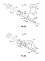
FIG. 3A is a perspective view illustrating a port and port introducer in accordance with an another embodiment of the present disclosure; -
FIG. 3B is a front view of the port introducer depicted inFIG. 3A ; -
FIG. 3C is a perspective view illustrating the port introducer accessing tissue and the port loaded within the port introducer; -
FIG. 3D is a perspective view illustrating the port securely positioned within tissue and the port introducer extracted from tissue; -
FIG. 4A is a perspective view of a port and port introducer in accordance with an embodiment of the present disclosure; -
FIG. 4A -1 is a cross-sectional view taken along line segment "4A-1-4A-1" ofFIG. 4A ; -
FIG. 4B is a side view of a rigid portion associated with the port introducer depicted inFIG. 4A ; -
FIG. 4C is a top elevational view of the rigid portion depicted inFIG. 4B ; -
FIG. 4D is a perspective view illustrating the port being loaded into the port introducer depicted inFIG. 4A ; -
FIG. 4E is a perspective view illustrating the port introducer accessing tissue and the port loaded within the port introducer; -
FIG. 4F is a perspective view illustrating the port securely positioned within tissue of a patient; -
FIG. 4G is a perspective view illustrating the port removed from tissue and the introducer being extracted from tissue; -
FIG. 4H is a perspective view of a port introducer in accordance with an embodiment of the present disclosure; -
FIG. 4H -1 is a cross-sectional view taken along line segment "4H-1-4H-1" ofFIG. 4H ; -
FIG. 4I is a side view of a rigid portion associated with the port introducer depicted inFIG. 4H ; and -
FIG. 4J is a top elevational view of the rigid portion depicted inFIG. 4I . - Particular embodiments of the present disclosure will be described herein with reference to the accompanying drawings. In the following description, well-known functions or constructions are not described in detail to avoid obscuring the present disclosure in unnecessary detail. As shown in the drawings and as described throughout the following descriptions, and as is traditional when referring to relative positioning on an object, the term "proximal" refers to the end of the device that is closer to the user and the term "distal" refers to the end of the apparatus that is further from the user.
- The port introducers according to the present disclosure are configured to facilitate the introduction of an access port, e.g., a foam port, within a surgical incision of a patient. It is envisioned that the port introducers may be used in connection with other surgical procedures utilizing natural or formed openings in a body cavity of a patient. Embodiments of the present disclosure are illustrated in
FIGS. 1A-4J . - With reference to
FIGS. 1A-1D , and initially with reference toFIG. 1A , an embodiment of aport introducer 10 is shown. In the embodiment illustrated inFIGS. 1A-1D ,port introducer 10 includes anintroducer assembly 100 that is suitable for use with asurgical foam port 200. Theport introducer 10 andfoam port 200 may be manufactured and sold separately or provided as a kit. -
Introducer assembly 100 includes a substantially rigid elongated introducer orhousing 102 dimensioned for at least partial introduction within an opening in tissue. In the embodiment illustrated inFIG. 1A-1D ,housing 102 is of a unitary construction formed by any suitable manufacturing methods including but not limited to injection molding, overmolding, etc.Housing 102 may be formed from any suitable biocompatible material including rigid such as stainless steel, titanium, polymeric material and/or a resilient elastomeric material. In embodiments,housing 102, or portion thereof, may be coated with or formed from alubricious material 104. More particularly, in the embodiment illustrated inFIGS. 1A-1D , aninternal surface 106 is coated with a layer of one or more types of fluoropolymers including without limitation, polytetrafluoroethylene (a.k.a. PTFE or Teflon®, manufactured by the E.I. du Pont de Nemours and Co. of Wilmington, Delaware, USA), seeFIG. 1A , for example. Coatinginternal surface 106 ofhousing 102 with alubricious material 104 decreases the coefficient of kinetic friction (µk) between theinternal surface 106 and theport 200 and, thus, facilitates movement of theport 200 throughhousing 102. In embodiments, thelubricious material 104 may be selected from the group consisting of polytetrafluoroethylene (PTFE), perfluoroalkoxy polymer resin (PFA), fluorinated ethylenepropylene (FEP). -
Housing 102 is configured to receive, compress and releasably secure theport 200 therein. With this purpose in mind,housing 102 includes anouter wall segment 102a defining a longitudinal axis "A-A" and asurgical port 200 passageway therethrough.Outer wall segment 102a includes a slotted tube configuration with open proximal (or trailing) and distal (or leading) ends 108 and 110, respectively.Housing 102 includes aproximal face 150 and adistal face 152. In an embodiment, theproximal end 108 may be closed. Alongitudinal slot 114 is disposed adjacent theproximal face 150 and may extend at least partially along a length of thehousing 102. In the embodiment illustrated inFIGS. 1A-1D , thelongitudinal slot 114 extends along the length of thehousing 102 from theproximal end 108 to thedistal end 110 such that thehousing 102 includes a generally "C" like configuration (seeFIG. 1A -1). A pair oftop edges longitudinal slot 114 and run parallel to the longitudinal axis "A-A" (seeFIGS. 1A -1 in conjunction withFIG. 1B ). Thelongitudinal slot 114 facilitates loading and unloading of theport 200 into thedistal end 110 of thehousing 102. Thelongitudinal slot 114 is proportioned to move theport 200 toward a compressed state as theport 200 is pushed within thelongitudinal slot 114 from thedistal end 110 of thehousing 102 toward theproximal end 108 of thehousing 102.Distal end 110 includes aleading edge 116 that is angled or slanted with respect totop edges leading edge 116 extends from a distal portion of thetop edges distal insertion tip 118. The angledleading edge 116 anddistal tip 118 facilitate loading and unloading of theport 200 into thehousing 102 and positioning thehousing 102 into a tissue tract. One or more types ofstructure 124 configured to manipulate tissue may be operably associated with thedistal end 110. More particularly,distal tip 118 includes a retractor having a generally "hook" like shape 124 (or other suitable structure), seeFIG. 1B . In this instance, theretractor 124 may be employed to retract tissue, such as, for example, prior to insertion of thehousing 102 into the tissue tract (FIG. 1C ).Retractor 124 includes a generally arcuate or curved configuration and extends distally from thedistal end 110 of thehousing 102 in a generally oblique relation with the longitudinal axis "A-A." Theretractor 124 may be a separate structure operably coupled to thehousing 102 at thedistal end 110 thereof, or theretractor 124 may be monolithically formed with thedistal tip 118. For example, a portion, e.g., thedistal face 152, of thedistal tip 118 may curve toward theproximal end 108 forming thehook 124. - In an embodiment, a gripping device or handle assembly may be operably coupled to the
proximal end 108. In the embodiment illustrated inFIGS. 1A-1D ,proximal end 108 includes ahandle assembly 112.Handle assembly 112 may operably couple to theproximal end 108 by any suitable means. For example, handleassembly 112 may be monolithically formed with theproximal end 108 or may be removably attached to the proximal end via a press or friction fit. Handle 112 assembly includes a generally "C" like configuration when viewed in cross-section.Handle assembly 112 includes proximal anddistal ends 132 and 134, respectively, each having arespective flange 136 and 138. Acircular recess 140 is defined between theflanges 136 and 138. Therecess 140 is configured to receive one or more fingers of a user. The recess provides additional leverage for the user and, thus, facilitates a user in pushing theport 200 through thelongitudinal slot 114 and from thehousing 102. While the drawings depict thelongitudinal slot 114 extending through the handle assembly, it is within the purview of the present disclosure to have the longitudinal slot not extend through thehandle assembly 112. - In the embodiment illustrated in
FIGS. 1A-1D , asurgical instrument 120 may be employed to push out, i.e., deploy thesurgical port 200 from thedistal end 110 of thehousing 102 when thehousing 102 is positioned within a tissue tract or an incision of the patient (FIG. 1D ). To this end, a surgical instrument in the form ofpush rod 120 or the like is receivable within thehandle assembly 112 and movable within at least a portion of thehousing 102. In the embodiment illustrated inFIGS. 1A-1D , thepush rod 120 includes aguide pin 122 that is configured to move within thelongitudinal slot 114. When thepush rod 120 is employed to push out, i.e., deploy thesurgical port 200 from thedistal end 110 of thehousing 102, the recess provides additional leverage to the user and, thus, allows a user to deploy thesurgical port 200 from thedistal end 110 of thehousing 102 with one hand. - As noted above,
port introducer assembly 100 is suitable for use with asurgical foam port 200. A brief description of asurgical port 200, and operative features associated therewith, now follows. -
Port 200 is of the foam type and is adapted to transition from a normally non-compressed or relaxed state or condition (FIGS. 1A and1D ) for affixing theport 200 within an incision or opening of a patient to a compressed condition (FIG. 1C ) when mounted to thehousing 102 for inserting theport 200 within the incision of a patient.Port 200 may be formed from any suitable bio-compatible material, such as, for example, athermoplastic elastomer. Port 200 is configured to receive one or more types of surgical instruments, e.g., laparoscopic and/or endoscopic instruments. With this purpose in mind,port 200 includes aport body 211 and may include one or more passageways oropenings 202 that extend from a proximal (or trailing) end 204 of thefoam port 200 to the distal (or leading)end 206 of thefoam port 200.Openings 202 may have any suitable geometric configuration. As shown in the representative drawings,openings 202 have a generally circular configuration. Trailingend 204 includes a generally circumferential configuration and includes aflange 208 that is configured to contact an outer surface of an abdominal wall of a patient (FIG. 1D ). Likewise, leadingend 206 includes a generally circumferential configuration and includes aflange 210 that is configured to contact an inner surface of an abdominal wall of a patient (FIG. 1D ). This configuration offlanges port 200 in a substantially fixed position when theport 200 is positioned within an incision of a patient. One example of aport 200 is disclosed in commonly assignedU.S. Patent Application Serial No. 12/244,024 filed, October 2, 2008 - In use,
port 200 may be inserted into the open end of thedistal end 110 and pushed into thelongitudinal slot 114 toward the proximal end 108 (FIG. 1B ). Onceport 200 is inserted into thelongitudinal slot 114,housing 102 may then be inserted into an opening or incision made within a tissue "T" of a patient (FIG. 1C ). Afterhousing 102 is properly positioned into the incision, theport 200 may be disengaged from thehousing 102 and into the incision where theport 200 will return to its non-compressed condition such that theport 200 is securely positioned within the incision (FIG. 1D ). In an embodiment, thepush rod 120 may be employed to push theport 200 through thelongitudinal slot 114 and from the opendistal end 110. Once theport 200 is securely positioned within the incision, one or more types of surgical instruments, e.g., endoscope, may be inserted through the one ormore apertures 202. - With reference to
FIGS. 2A-2D , and initially with reference toFIG. 2A , an embodiment of aport introducer 300 is shown. In the embodiment illustrated inFIGS. 2A-2D ,port introducer 300 includes anintroducer assembly 400 that is suitable for use withport 200. The components ofport introducer 300 may be formed from any of the hereinbefore disclosed materials. -
Introducer assembly 400 is substantially similar to theintroducer assembly 100 described above. So as not to obscure the present disclosure with redundant information, only those features unique tointroducer assembly 400 will described hereinafter. - Unlike the
housing 102, a portion of an elongated introducer orhousing 402 is movable between a first or generally open position for receiving at least a portion of theport 200 to a second or generally approximated position for securing and moving theport 200 to a compressed state. With this purpose in mind, thehousing 402 includes proximal anddistal faces Housing 402 includes a slotted tube configuration defined by two pivotably coupledouter wall segments FIGS. 2A-2D , ahinge 406, or the like, operably couples theouter wall segments hinge 406 facilitates movement of thehousing 402 between the first and second positions.Hinge 406 may be any suitable type of hinge, e.g., living, pinned, strap, and so forth. In the embodiment illustrated inFIGS. 2A-2D , hinge 406 is aliving hinge 406 that extends the length of thehousing 402 along the distal face 450a thereof. - In an embodiment, one or
more locking members 420, e.g., clamp, latch, drawstring, etc., may operably couple to or be operably associated with thehousing 402. The locking member(s) may be configured to allow theouter wall segments hinge 406 in the first position during insertion of thehousing 402 into an incision. In the embodiment illustrated inFIGS. 2A-2D , the lockingmember 420 is disposed along theproximal face 450 adjacent a medial portion of thehousing 402, seeFIG. 2A , More particularly, adrawstring 422 is operably disposed onouter wall segment 402a and receivable within a corresponding receivingstructure 424 operably disposed on theouter wall segment 402b. In use, thedrawstring 422 is threaded through the receivingstructure 424 and manipulated by a user to substantially maintain thehinge 406 in the first position during insertion of thehousing 402 into an incision. - Alternatively, the
housing 402 may be devoid of a lockingmember 420 and during insertion of thehousing 402 into an incision a user may simply grasp each of theouter wall segments hinge 406 is substantially maintained in the first position. - In use,
outer wall segments FIG. 2A ). Withhousing segments port 200 may be positioned between theouter wall segments outer wall segments port 200 is inserted into the housing, thehousing 402 may then be inserted into an opening or incision made within a tissue "T" of a patient (FIG. 2C ). Afterhousing 402 is properly positioned into the incision, theport 200 may be disengaged from thehousing 402 and into the incision where theport 200 will return to its non-compressed condition such that theport 200 is securely positioned within the incision (FIG. 2D ). In an embodiment, theouter wall segments port 200 from thehousing 402. Alternatively, or in combination therewith, thepush rod 120 may be employed to push theport 200 through the longitudinal slot 414 and from the open distal end 410. Once theport 200 is securely positioned within the incision, one or more types of surgical instruments, e.g., endoscope, may be inserted through the one ormore apertures 202. - With reference to
FIGS. 3A-3E , and initially with reference toFIG. 3A , an embodiment of aport introducer 500 is shown. In the embodiment illustrated inFIGS. 3A-3E ,port introducer 500 includes anintroducer assembly 600 that is suitable for use withport 200. The components ofport introducer mechanism 500 may be formed from any of the hereinbefore disclosed materials. -
Introducer assembly 600 includes an elongated introducer orhousing 602 configured to receive, compress and releasably secure theport 200 therein. With this purpose in mind,housing 602 includes anouter wall segment 606 defining a longitudinal axis "A-A."Housing 602 includingouter wall segment 606 includes a 'shoe horn" like configuration. More particularly,housing 602 includes open (or trailing) proximal and distal (or leading) ends 608 and 610, respectively. A relatively flatdistal face 652 extends along a length of thehousing 602. A longitudinal channel orslot 614 is disposed adjacent aproximal face 650 and extends along the length of thehousing 602 from theproximal end 608 to thedistal end 610 such that thehousing 602 includes an oval, generally "C" like configuration (seeFIG. 3B , for example). A pair oftop edges longitudinal slot 614 and run parallel to the longitudinal axis "A-A" (seeFIGS. 3A in conjunction withFIG. 3B ). Thelongitudinal slot 614 facilitates loading and unloading of theport 200 into thedistal end 610 of thehousing 102. Thelongitudinal slot 614 is proportioned to move theport 200 toward a compressed state as theport 200 is pushed within thelongitudinal slot 614 from thedistal end 610 of thehousing 602 toward theproximal end 608 of thehousing 602. - A
handle section 620 operably couples to theproximal end 608.Handle section 620 may operably couple to theproximal end 608 of the housing by any suitable means. In the embodiment illustrated inFIGS. 3A-3D ,handle section 620 is monolithically formed with thehousing 602. In embodiments, handlesection 620 may be joined tohousing 602 via welding, soldering, brazing, and so forth. Alternatively, handlesection 620 may operably couple to thehousing 620 via a rivet, bolt, screw, and so forth. Thehandle section 620 includes a "ladle" like configuration with one or more curved surfaces. More particularly, handlesection 620 includes a generally arcuate or curved (e.g., convex)proximal end 622 and a generally arcuate or curved (e.g., concave)distal end 625. Aportion 626 of theproximal end 622 serves as surface for a user to grip. Aportion 628 of thedistal end 624 serves as a shoulder that pushes against theport 200 and maintains theport 200 within thehousing 602, such as, for example, during insertion thehousing 602 into the tissue tract. - In use,
port 200 may be positioned within the housing 602 (FIG. 3A ). Onceport 200 is inserted into thehousing 602, thehousing 602 may then be inserted into an opening or incision made within a tissue "T" of a patient (FIG. 3C ). Afterhousing 602 is properly positioned into the incision, theport 200 may be disengaged from thehousing 602 and into the incision where theport 200 will return to its non-compressed condition such that theport 200 is securely positioned within the incision (FIG. 3D ). In an embodiment, thepush rod 120 may be employed to push theport 200 through thelongitudinal slot 614 and from the opendistal end 610. Once theport 200 is securely positioned within the incision, one or more types of surgical instruments, e.g., endoscope, may be inserted through the one ormore apertures 202. - With reference to
FIGS. 4A-4G , and initially with reference toFIG. 4A , an embodiment of aport introducer 700 is shown. In the embodiment illustrated inFIGS. 4A-4G ,port introducer 700 includes anintroducer assembly 800 that is suitable for use withport 200. The components ofport introducer mechanism 700 may be formed from any of the hereinbefore disclosed materials. -
Introducer assembly 800 includes an elongated introducer orhousing 802. In the embodiment illustrated inFIG. 4A-4G ,housing 802 is of a unitary construction formed by any of the aforementioned manufacturing methods and from any of the aforementioned materials. In embodiments,housing 802 is formed from one or more elastomeric materials, such as, for example, polypropylene, polyethylene, etc. In the embodiment illustrated inFIGS. 4A-4D , a portion (e.g., a rigid portion 804) of thehousing 802 may be formed from a material that is substantially rigid and a portion (e.g., a flexible portion 806) of thehousing 802 may be formed from a material that is substantially flexible (e.g., polyethylene). The significance ofhousing 802 having substantially rigid andflexible portions housing 802, or portion thereof, may be coated with or formed from any of the aforementionedlubricious materials 104. -
Housing 802 is configured to receive, compress and releasably secure theport 200 therein. With this purpose in mind,housing 802 includes a substantiallyrigid portion 804 and supporting aflexible portion 806 forming an outer wall segment (FIG. 4A-1 ).Rigid portion 804 extends the length of thehousing 802 and includes a generally "banana" like configuration (seeFIGS. 4A and4B , whereFIG. 4B illustrates therigid portion 804 separated from the flexible portion 806).Rigid portion 804 forms adistal end 810 of housing 802 (FIGS. 4A ,4B and 4C , whereFIG. 4C illustrates therigid portion 806 separated from the flexible portion 804).Rigid portion 804 defines and/or includes a rigid "backbone" 812 that extends at least partially along the length of the rigid portion 804 (as best seen inFIG. 4C ). The rigid "backbone" 812 provides additional structural integrity for thehousing 802.Flexible portion 806 operably couples to therigid portion 804. In the embodiment illustrated inFIGS. 4A-4G ,flexible portion 806 is overmolded to the rigid portion 804 (FIG. 4A -1) and substantially encases therigid portion 804.Flexible portion 806 extends substantially the length of therigid portion 804.Flexible portion 806 is movable between a first position for securing theport 200 therein (seeFIG. 4A-1 in combination withFIG. 4D , for example) to a second position for facilitating removal of thehousing 802 from a tissue tract (shown phantomly inFIG. 4A -1). With this purpose in mind,flexible portion 806 includes two generally upright collapsibleouter sidewalls distal end 810. Theouter sidewalls port 200 is not positioned within thehousing 802 and a force is applied to theouter sidewalls housing 802 is being removed from a tissue tract. Theflexible member 806 includingouter sidewalls longitudinal slot 818 extending at least partially the length of thehousing 802.Longitudinal slot 818 functions in a manner similar to that of the previously described slots, e.g.,longitudinal slot 114. Each of theouter sidewalls top edges top edges port 200 within thehousing 802.Flexible member 806 includingouter sidewalls rigid portion 804 define aproximal end 820 that includes anopening 822 dimensioned to securely receive a portion (e.g., a distal end 206) of thesurgical port 200.Proximal end 820 is dimensioned to move theport 200 toward a compressed state as theport 200 is pushed from theproximal end 820 of thehousing 802 toward thedistal end 810 of thehousing 802.Distal end 810 includes a relativelyblunt tip 824. Alternatively,distal end 810 may include a relatively sharp tip configuration (not explicitly shown). - A
retrieval structure 828 operably couples the distal end 810 (FIG. 4A ).Retrieval structure 828 couples to anaperture 830 locatedadjacent tip 824. Theretrieval structure 828 may be any suitable structure including but not limited suture, string, filament, and so forth. In the embodiment illustrated inFIGS. 4A-4G , retrieval structure is asuture 828 including anend 834 that is looped through theopening 830 and subsequently knotted. In an embodiment,suture 828 may be operably coupled tohousing 802 by other suitable coupling means, e.g., adhesives, over-molding, and so forth. Suture 828 may have any suitable length. In the embodiment illustrated inFIGS. 4A-4G ,suture 828 includes a length that allows thesuture 828 to remain outside the tissue tract after thehousing 802 is pushed into and completely through the tissue tract, such that thesuture 828 may be employed to pull thehousing 802 out of and from the tissue tract, described in greater detail below. - In an embodiment, surgical instrument may be employed to disengage the
housing 802 from thesurgical port 200 when thehousing 802 is positioned within a tissue tract or an incision of the patient. To this end, a surgical instrument in the form of apush rod 120 or the like is receivable within one or more of theopenings 202 of theport 200. - In use, the
port 200 may be positioned within theproximal end 820 of thehousing 802. Onceport 200 is secured to thehousing 802,distal end 810 ofhousing 802 may then be inserted into an opening or incision made within a tissue "T" of a patient (FIG. 4E ). Afterhousing 802 is inserted into the incision, theport 200 is disengaged, e.g., via a twisting action of thehousing 802, from thehousing 802, where theport 200 will return to its non-compressed condition such that theport 200 is securely positioned within the incision (seeFIG. 4F ). In an instance where, thehousing 802 is completely inserted through the incision (as shown inFIG. 4F , for example), thehousing 802 may be disengaged from theport 206 via one or more surgical instruments, e.g., apush rod 120. In this instance, the suture 832 may be employed to retrieve the housing 802 (FIG. 4G ). During extraction of thehousing 802 from the incision, thecollapsible walls FIG. 4A -1 and 4G, facilitating removal of the housing from the tissue tract. - With reference to
FIGS. 4H-4J an alternate embodiment of aport introducer 700 is shown designated 700a. Port introducer 700a is substantially similar toport introducer 700. So as not to obscure the present disclosure with redundant information only those features unique toport introducer 700a will be described herein. - In the embodiment illustrated in
FIGS. 4H-4J , an elongated introducer orhousing 802a includes one or more rigid supports orfingers 875 configured to provide added structural integrity tohousing 802a and/or aflexible portion 806a, e.g., collapsibleouter sidewalls housing 802a. In the illustrated embodiment,housing 802a includes a pair offingers 875.Fingers 875 operably couple to adistal end 810a of arigid portion 804a and extend proximally toward aproximal end 820a ofrigid portion 804a. In the embodiment illustrated inFIGS. 4H-4J ,fingers 875 are disposed above arigid backbone 812a and encased byflexible member 806a, seeFIG. 4I in combination withFIG. 4H-1 . More particularly,fingers 875 are in spaced apart relation relative to each other and are laterally disposed on opposite sides of arigid backbone 812a, seeFIG. 4H-1 in combination withFIG. 4J . Operation of introducer 800a includingfingers 875 is substantially similar to that ofintroducer 800. One distinguishing feature of the introducer 800a when compared tointroducer 800 is that thefingers 875 ofhousing 802a add an amount of predetermined rigidity to thecollapsible walls - It will be understood that various modifications may be made to the embodiments disclosed herein. Therefore, the above description should not be construed as limiting, but merely as an exemplification of preferred embodiments. Those skilled in the art will envision other modifications within the scope and spirit of the present disclosure. Such modifications and variations are intended to come within the scope of the following claims.
The inventions may be described by reference to the following numbered paragraphs:- - 1. A surgical apparatus for permitting access to tissue, which comprises:
- an elongated introducer including an outer wall segment defining a longitudinal axis and a longitudinal port passage extending therethrough, the outer wall segment having a longitudinal slot in communication with the port passage, the elongated introducer dimensioned for at least partial introduction within an opening in tissue; and
- a surgical port for providing access to underlying tissue, the surgical port including a port body having leading and trailing ends, an intermediate segment disposed between the leading and trailing ends, at least one passageway for reception and passage of a surgical instrument, the port body being mounted to the elongated introducer with one of the leading and trailing ends disposed within the port passage and with the intermediate segment extending through the longitudinal slot and the other of the leading and trailing end external of the elongated introducer, the port body dimensioned to be advanced within the port passage for deployment through the opening in the tissue as generally directed by the elongated introducer, the port body comprising a compressible material adapted to transition from a compressed state when mounted to the elongated introducer to a released state when deployed from the elongated introducer.
- 2. The surgical apparatus according to
paragraph 1 wherein the elongated introducer defines introducer leading and trailing ends, and further including a retractor segment adjacent the introducer leading end, the retractor segment dimensioned and configured to retract tissue surrounding the opening. - 3. The surgical apparatus according to paragraph 2 wherein the retractor segment defines an arcuate profile.
- 4. The surgical apparatus according to paragraph 2 wherein the outer wall segment of the elongated introducer is substantially arcuate along a major portion of the length thereof.
- 5. The surgical apparatus according to paragraph 2 wherein the retractor segment defines a general hook-shape and is arranged in oblique relation with the longitudinal axis.
- 6. The surgical apparatus according to
paragraph 1 including a pusher member at least partially disposed within the longitudinal port passage of the elongated introducer, the pusher member adapted for longitudinal advancement to engage and deploy the port body from the introducer and within the opening in tissue. - 7. The surgical apparatus according to
paragraph 1 wherein the elongated introducer includes a handle mounted to the outer wall segment, the handle dimensioned for engagement by the user. - 8. The surgical apparatus according to
paragraph 1 wherein the elongated introducer is substantially rigid. - 9. The surgical apparatus according to
paragraph 1 wherein at least a portion of the longitudinal slot is coated with a lubricious material. - 10. The surgical apparatus according to
paragraph 1 wherein at least the outer wall segment of the elongated introducer includes first and second movable segments, the first and second movable segments adapted for movement between a generally open position and a generally approximated position, wherein, when in the open position, the one of the leading and trailing ends of the port body is positionable within the port passage, and, when in the approximated position, the port body is moved to the compressed state with the one of the leading and trailing ends disposed within the port passage, the intermediate segment extending through the longitudinal slot and the other of the leading and trailing end external of the elongated introducer. - 11. The surgical apparatus according to
paragraph 10 wherein the first and second movable segments are adapted for pivotal movement relative to each other. - 12. The surgical apparatus according to
paragraph 1 wherein the elongated introducer includes a substantially flexible portion and a rigid portion. - 13. The surgical apparatus according to paragraph 12 wherein the substantially flexible portion is movable between a first position for securing the port therein to a second position for facilitating removal of the elongated introducer from the opening in the tissue.
- 14. The surgical apparatus according to paragraph 13 wherein the substantially flexible portion is dimensioned to extend substantially the length of the rigid portion.
- 15. The surgical apparatus according to paragraph 2 wherein the leading end of the elongated introducer is substantially open and the trailing end is closed.
- 16. The surgical apparatus according to
paragraph 1 wherein a retrieval structure is operably coupled to the distal end of the elongated introducer. - 17. The surgical apparatus according to paragraph 16 wherein the retrieval structure is selected from the group consisting of a suture, string and filament.
Claims (15)
- A surgical apparatus for permitting access to tissue, which comprises:an elongated introducer including an outer wall segment defining a longitudinal axis and a longitudinal port passage extending therethrough, the outer wall segment having a longitudinal slot in communication with the port passage, the elongated introducer dimensioned for at least partial introduction within an opening in tissue; anda surgical port for providing access to underlying tissue, the surgical port including a port body having leading and trailing ends, an intermediate segment disposed between the leading and trailing ends, at least one passageway for reception and passage of a surgical instrument, the port body being mounted to the elongated introducer with one of the leading and trailing ends disposed within the port passage and with the intermediate segment extending through the longitudinal slot and the other of the leading and trailing end external of the elongated introducer, the port body dimensioned to be advanced within the port passage for deployment through the opening in the tissue as generally directed by the elongated introducer, the port body comprising a compressible material adapted to transition from a compressed state when mounted to the elongated introducer to a released state when deployed from the elongated introducer.
- The surgical apparatus according to claim 1 wherein the elongated introducer defines introducer leading and trailing ends, and further including a retractor segment adjacent the introducer leading end, the retractor segment dimensioned and configured to retract tissue surrounding the opening.
- The surgical apparatus according to claim 2 wherein the retractor segment defines an arcuate profile, preferably wherein the outer wall segment of the elongated introducer is substantially arcuate along a major portion of the length thereof.
- The surgical apparatus according to claim 2 wherein the retractor segment defines a general hook-shape and is arranged in oblique relation with the longitudinal axis.
- The surgical apparatus according to any preceding claim including a pusher member at least partially disposed within the longitudinal port passage of the elongated introducer, the pusher member adapted for longitudinal advancement to engage and deploy the port body from the introducer and within the opening in tissue.
- The surgical apparatus according to any preceding claim wherein the elongated introducer includes a handle mounted to the outer wall segment, the handle dimensioned for engagement by the user.
- The surgical apparatus according to any preceding claim wherein the elongated introducer is substantially rigid.
- The surgical apparatus according to any preceding claim wherein at least a portion of the longitudinal slot is coated with a lubricious material.
- The surgical apparatus according to any preceding claim wherein at least the outer wall segment of the elongated introducer includes first and second movable segments, the first and second movable segments adapted for movement between a generally open position and a generally approximated position, wherein, when in the open position, the one of the leading and trailing ends of the port body is positionable within the port passage, and, when in the approximated position, the port body is moved to the compressed state with the one of the leading and trailing ends disposed within the port passage, the intermediate segment extending through the longitudinal slot and the other of the leading and trailing end external of the elongated introducer; preferably wherein the first and second movable segments are adapted for pivotal movement relative to each other.
- The surgical apparatus according to any of claims 1 to 6 wherein the elongated introducer includes a substantially flexible portion and a rigid portion.
- The surgical apparatus according to claim 10 wherein the substantially flexible portion is movable between a first position for securing the port therein to a second position for facilitating removal of the elongated introducer from the opening in the tissue.
- The surgical apparatus according to claim 11 wherein the substantially flexible portion is dimensioned to extend substantially the length of the rigid portion.
- The surgical apparatus according to claim 2 wherein the leading end of the elongated introducer is substantially open and the trailing end is closed.
- The surgical apparatus according to any preceding claim wherein a retrieval structure is operably coupled to the distal end of the elongated introducer.
- The surgical apparatus according to claim 14 wherein the retrieval structure is selected from the group consisting of a suture, string and filament.
Applications Claiming Priority (2)
| Application Number | Priority Date | Filing Date | Title |
|---|---|---|---|
| US201261604644P | 2012-02-29 | 2012-02-29 | |
| US13/755,244 US9271639B2 (en) | 2012-02-29 | 2013-01-31 | Surgical introducer and access port assembly |
Publications (2)
| Publication Number | Publication Date |
|---|---|
| EP2633827A1 true EP2633827A1 (en) | 2013-09-04 |
| EP2633827B1 EP2633827B1 (en) | 2017-04-05 |
Family
ID=47826932
Family Applications (1)
| Application Number | Title | Priority Date | Filing Date |
|---|---|---|---|
| EP13156882.6A Not-in-force EP2633827B1 (en) | 2012-02-29 | 2013-02-27 | Surgical introducer and access port assembly |
Country Status (4)
| Country | Link |
|---|---|
| US (2) | US9271639B2 (en) |
| EP (1) | EP2633827B1 (en) |
| AU (1) | AU2013200889A1 (en) |
| CA (1) | CA2805209A1 (en) |
Cited By (1)
| Publication number | Priority date | Publication date | Assignee | Title |
|---|---|---|---|---|
| EP3000433A1 (en) * | 2014-09-29 | 2016-03-30 | Sofradim Production | Device for introducing a prosthesis for hernia treatment into an incision |
Families Citing this family (33)
| Publication number | Priority date | Publication date | Assignee | Title |
|---|---|---|---|---|
| BRPI0817421A2 (en) * | 2007-10-05 | 2015-06-16 | Tyco Healthcare | Sealing fastener for use in surgical procedures |
| USD738500S1 (en) * | 2008-10-02 | 2015-09-08 | Covidien Lp | Seal anchor for use in surgical procedures |
| US9421032B2 (en) * | 2010-06-16 | 2016-08-23 | Covidien Lp | Seal port with blood collector |
| US9549747B2 (en) * | 2012-01-23 | 2017-01-24 | Covidien Lp | Reusable surgical retrieval apparatus with disposable cartridge assembly |
| US10064649B2 (en) | 2014-07-07 | 2018-09-04 | Covidien Lp | Pleated seal for surgical hand or instrument access |
| US9707011B2 (en) | 2014-11-12 | 2017-07-18 | Covidien Lp | Attachments for use with a surgical access device |
| US11160682B2 (en) | 2017-06-19 | 2021-11-02 | Covidien Lp | Method and apparatus for accessing matter disposed within an internal body vessel |
| US10828065B2 (en) | 2017-08-28 | 2020-11-10 | Covidien Lp | Surgical access system |
| US10675056B2 (en) | 2017-09-07 | 2020-06-09 | Covidien Lp | Access apparatus with integrated fluid connector and control valve |
| US11172957B2 (en) | 2018-02-07 | 2021-11-16 | Stryker Corporation | Surgical cannula and methods of use |
| US11389193B2 (en) | 2018-10-02 | 2022-07-19 | Covidien Lp | Surgical access device with fascial closure system |
| US11457949B2 (en) | 2018-10-12 | 2022-10-04 | Covidien Lp | Surgical access device and seal guard for use therewith |
| US11166748B2 (en) | 2019-02-11 | 2021-11-09 | Covidien Lp | Seal assemblies for surgical access assemblies |
| US10792071B2 (en) | 2019-02-11 | 2020-10-06 | Covidien Lp | Seals for surgical access assemblies |
| US11000313B2 (en) | 2019-04-25 | 2021-05-11 | Covidien Lp | Seals for surgical access devices |
| US11413068B2 (en) | 2019-05-09 | 2022-08-16 | Covidien Lp | Seal assemblies for surgical access assemblies |
| US11259840B2 (en) | 2019-06-21 | 2022-03-01 | Covidien Lp | Valve assemblies for surgical access assemblies |
| US11357542B2 (en) | 2019-06-21 | 2022-06-14 | Covidien Lp | Valve assembly and retainer for surgical access assembly |
| US11259841B2 (en) | 2019-06-21 | 2022-03-01 | Covidien Lp | Seal assemblies for surgical access assemblies |
| US11413065B2 (en) | 2019-06-28 | 2022-08-16 | Covidien Lp | Seal assemblies for surgical access assemblies |
| US11399865B2 (en) | 2019-08-02 | 2022-08-02 | Covidien Lp | Seal assemblies for surgical access assemblies |
| US11523842B2 (en) | 2019-09-09 | 2022-12-13 | Covidien Lp | Reusable surgical port with disposable seal assembly |
| US11432843B2 (en) | 2019-09-09 | 2022-09-06 | Covidien Lp | Centering mechanisms for a surgical access assembly |
| US11812991B2 (en) | 2019-10-18 | 2023-11-14 | Covidien Lp | Seal assemblies for surgical access assemblies |
| US11464540B2 (en) | 2020-01-17 | 2022-10-11 | Covidien Lp | Surgical access device with fixation mechanism |
| US11576701B2 (en) | 2020-03-05 | 2023-02-14 | Covidien Lp | Surgical access assembly having a pump |
| US11642153B2 (en) | 2020-03-19 | 2023-05-09 | Covidien Lp | Instrument seal for surgical access assembly |
| US11541218B2 (en) | 2020-03-20 | 2023-01-03 | Covidien Lp | Seal assembly for a surgical access assembly and method of manufacturing the same |
| US11446058B2 (en) | 2020-03-27 | 2022-09-20 | Covidien Lp | Fixture device for folding a seal member |
| US11717321B2 (en) | 2020-04-24 | 2023-08-08 | Covidien Lp | Access assembly with retention mechanism |
| US11622790B2 (en) | 2020-05-21 | 2023-04-11 | Covidien Lp | Obturators for surgical access assemblies and methods of assembly thereof |
| US11751908B2 (en) | 2020-06-19 | 2023-09-12 | Covidien Lp | Seal assembly for surgical access assemblies |
| JP2023552813A (en) * | 2020-12-09 | 2023-12-19 | ポータル アクセス,インク. | Squeezable subcutaneous port |
Citations (5)
| Publication number | Priority date | Publication date | Assignee | Title |
|---|---|---|---|---|
| US6171282B1 (en) * | 1999-07-23 | 2001-01-09 | Edgar K. Ragsdale | Soft cannula and methods for use |
| US20040092796A1 (en) * | 1999-10-14 | 2004-05-13 | John Butler | Wound retractor system |
| US20100100043A1 (en) * | 2007-10-05 | 2010-04-22 | Racenet Danyel J | Flexible Access Device For Use In Surgical Procedure |
| US20100204548A1 (en) * | 2007-06-05 | 2010-08-12 | Frank Bonadio | Instrument Access Device |
| US20100249524A1 (en) * | 2009-03-31 | 2010-09-30 | Ransden Jeffrey E | Foam port and introducer assembly |
Family Cites Families (236)
| Publication number | Priority date | Publication date | Assignee | Title |
|---|---|---|---|---|
| US4016884A (en) | 1975-07-02 | 1977-04-12 | Kwan Gett Clifford S | Atriotomy access device |
| US4183357A (en) | 1976-08-02 | 1980-01-15 | Bentley Laboratories, Inc. | Chronic transcutaneous implant assembly for enterostomies |
| US4112932A (en) | 1977-02-24 | 1978-09-12 | Chiulli Robert D | Laparoscopic cannula |
| US4402683A (en) | 1981-12-28 | 1983-09-06 | Kopman Ercument A | Cannula introducer |
| GB2161389B (en) | 1984-07-05 | 1988-06-08 | Wolf Gmbh Richard | Instrument insert for a uretero-renoscope |
| US4863438A (en) | 1985-11-29 | 1989-09-05 | Applied Medical Technology, Inc. | Low profile gastrostomy device |
| US4863430A (en) | 1987-08-26 | 1989-09-05 | Surgical Dynamics, Inc. | Introduction set with flexible trocar with curved cannula |
| FR2641692A1 (en) | 1989-01-17 | 1990-07-20 | Nippon Zeon Co | Plug for closing an opening for a medical application, and device for the closure plug making use thereof |
| US5176697A (en) | 1989-04-06 | 1993-01-05 | Hasson Harrith M | Laparoscopic cannula |
| US5514153A (en) | 1990-03-02 | 1996-05-07 | General Surgical Innovations, Inc. | Method of dissecting tissue layers |
| US5345927A (en) | 1990-03-02 | 1994-09-13 | Bonutti Peter M | Arthroscopic retractors |
| US5990382A (en) | 1990-08-29 | 1999-11-23 | Biomedical Enterprises, Inc. | Method and implant for surgical manipulation of bone |
| US5073169A (en) | 1990-10-02 | 1991-12-17 | Steve Raiken | Trocar support |
| DE4034705A1 (en) | 1990-10-31 | 1992-05-07 | Martin Neumann | WOUND CLOSURE |
| US5159921A (en) | 1990-11-27 | 1992-11-03 | Hoover Rocklin L | Surgical retractor |
| US5082005A (en) | 1990-12-18 | 1992-01-21 | New England Deaconess Hospital | Surgical access device |
| US5242409A (en) | 1991-05-16 | 1993-09-07 | Applied Medical Resources Corporation | Flexible access device |
| US5836871A (en) | 1991-05-29 | 1998-11-17 | Origin Medsystems, Inc. | Method for lifting a body wall using an inflatable lifting apparatus |
| FR2686256A1 (en) | 1992-01-17 | 1993-07-23 | Nycomed Ingenor Sa Lab | Dilation catheter |
| US5269772A (en) | 1992-01-24 | 1993-12-14 | Wilk Peter J | Laparoscopic cannula assembly and associated method |
| US5183471A (en) | 1992-01-24 | 1993-02-02 | Wilk Peter J | Laparoscopic cannula |
| US5257973A (en) | 1992-02-05 | 1993-11-02 | Raul Villasuso | Sealing sleeve and method for laparoscopy |
| US5334143A (en) | 1992-04-17 | 1994-08-02 | Carroll Brendon J | Method to remove common bile duct stones |
| US5540711A (en) | 1992-06-02 | 1996-07-30 | General Surgical Innovations, Inc. | Apparatus and method for developing an anatomic space for laparoscopic procedures with laparoscopic visualization |
| US5407427A (en) | 1992-06-16 | 1995-04-18 | Loma Linda University Medical Center | Trocar facilitator for endoscopic surgery |
| GR930100244A (en) | 1992-06-30 | 1994-02-28 | Ethicon Inc | Flexible endoscopic surgical port |
| US5312391A (en) | 1992-07-29 | 1994-05-17 | Wilk Peter J | Laparoscopic instrument assembly |
| US5330486A (en) | 1992-07-29 | 1994-07-19 | Wilk Peter J | Laparoscopic or endoscopic anastomosis technique and associated instruments |
| US5511564A (en) | 1992-07-29 | 1996-04-30 | Valleylab Inc. | Laparoscopic stretching instrument and associated method |
| US5395367A (en) | 1992-07-29 | 1995-03-07 | Wilk; Peter J. | Laparoscopic instrument with bendable shaft and removable actuator |
| US5242415A (en) | 1992-08-14 | 1993-09-07 | L-Vad Technology, Inc. | Percutaneous access device |
| US5257975A (en) | 1992-08-14 | 1993-11-02 | Edward Weck Incorporated | Cannula retention device |
| US5375588A (en) | 1992-08-17 | 1994-12-27 | Yoon; Inbae | Method and apparatus for use in endoscopic procedures |
| US5540648A (en) | 1992-08-17 | 1996-07-30 | Yoon; Inbae | Medical instrument stabilizer with anchoring system and methods |
| US5797960A (en) | 1993-02-22 | 1998-08-25 | Stevens; John H. | Method and apparatus for thoracoscopic intracardiac procedures |
| US5795290A (en) | 1993-07-09 | 1998-08-18 | Bioplexus Corporation | Apparatus for holding intestines out of an operative field |
| US5366478A (en) | 1993-07-27 | 1994-11-22 | Ethicon, Inc. | Endoscopic surgical sealing device |
| US5507758A (en) | 1993-08-25 | 1996-04-16 | Inlet Medical, Inc. | Insertable suture grasping probe guide, and methodology for using same |
| US5803921A (en) | 1994-02-18 | 1998-09-08 | Gaya Limited | Access port device for use in surgery |
| US5480410A (en) | 1994-03-14 | 1996-01-02 | Advanced Surgical, Inc. | Extracorporeal pneumoperitoneum access bubble |
| US5813409A (en) | 1994-09-02 | 1998-09-29 | Medical Creative Technologies, Inc. | Surgical apparatus |
| US5569205A (en) | 1994-07-14 | 1996-10-29 | Hart; Charles C. | Multiport trocar |
| US5460170A (en) | 1994-08-23 | 1995-10-24 | Hammerslag; Julius G. | Adjustable surgical retractor |
| US5514133A (en) | 1994-08-26 | 1996-05-07 | Golub; Robert | Access device for endoscopic surgery |
| US5522791A (en) | 1994-08-31 | 1996-06-04 | Leyva; Horacio A. | Apparatus for retracting an incision and inflating an abdominal cavity |
| US5653705A (en) | 1994-10-07 | 1997-08-05 | General Surgical Innovations, Inc. | Laparoscopic access port for surgical instruments or the hand |
| US5672168A (en) | 1994-10-07 | 1997-09-30 | De La Torre; Roger A. | Laparoscopic access port for surgical instruments or the hand |
| US5651771A (en) | 1994-11-07 | 1997-07-29 | Applied Medical Resources Corporation | Adjustable surgical clamp |
| US5713869A (en) | 1995-03-08 | 1998-02-03 | Morejon; Orlando | Trocar assembly |
| US5713858A (en) | 1995-04-28 | 1998-02-03 | Medtronic, Inc. | Permanently implantable guiding catheter |
| US5741298A (en) | 1995-04-28 | 1998-04-21 | Macleod; Cathel | Method and devices for video-assisted surgical techniques |
| US5899208A (en) | 1995-05-08 | 1999-05-04 | Gaya Limited | Hand access port |
| US5634937A (en) | 1995-05-19 | 1997-06-03 | General Surgical Innovations, Inc. | Skin seal with inflatable membrane |
| US5964781A (en) | 1995-05-19 | 1999-10-12 | General Surgical Innovations, Inc. | Skin seal with inflatable membrane |
| US5601581A (en) | 1995-05-19 | 1997-02-11 | General Surgical Innovations, Inc. | Methods and devices for blood vessel harvesting |
| US5634911A (en) | 1995-05-19 | 1997-06-03 | General Surgical Innovations, Inc. | Screw-type skin seal with inflatable membrane |
| US5997515A (en) | 1995-05-19 | 1999-12-07 | General Surgical Innovations, Inc. | Screw-type skin seal with inflatable membrane |
| US5524644A (en) | 1995-06-09 | 1996-06-11 | Medical Creative Technologies, Inc. | Incrementally adjustable incision liner and retractor |
| US5683378A (en) | 1995-06-27 | 1997-11-04 | Christy; William J. | Endoscopic wound access and anchoring device method |
| US6605063B2 (en) | 1998-09-21 | 2003-08-12 | Gerald G. Bousquet | Transcutaneous access device |
| US5545179A (en) | 1995-07-21 | 1996-08-13 | Ethicon Endo-Surgery, Inc. | Endoscopic access assembly |
| US5782817A (en) | 1995-11-06 | 1998-07-21 | Cordis Corporation | Catheter introducer having toroidal valve |
| US5785715A (en) | 1995-12-07 | 1998-07-28 | Schatz; Richard A. | Retrieval shuttle |
| US6576009B2 (en) | 1995-12-01 | 2003-06-10 | Medtronic Ave, Inc. | Bifurcated intraluminal prostheses construction and methods |
| US5746764A (en) | 1995-12-04 | 1998-05-05 | Atrion Medical Products, Inc. | Stent compression instrument |
| US5894843A (en) | 1996-02-20 | 1999-04-20 | Cardiothoracic Systems, Inc. | Surgical method for stabilizing the beating heart during coronary artery bypass graft surgery |
| US5649550A (en) | 1996-02-26 | 1997-07-22 | Medical Creative Technologies, Inc. | Surgical retractor liner and integral drape assembly |
| US5941898A (en) | 1996-02-29 | 1999-08-24 | Stephen P. Moenning | Apparatus and method for moving sealing members of a medical apparatus between a first orientation and a second orientation |
| US5951588A (en) | 1996-02-29 | 1999-09-14 | Moenning; Stephen P. | Apparatus and method for protecting a port site opening in the wall of a body cavity |
| US6814700B1 (en) | 1996-03-04 | 2004-11-09 | Heartport, Inc. | Soft tissue retractor and method for providing surgical access |
| US6048309A (en) | 1996-03-04 | 2000-04-11 | Heartport, Inc. | Soft tissue retractor and delivery device therefor |
| US5817062A (en) | 1996-03-12 | 1998-10-06 | Heartport, Inc. | Trocar |
| US5685857A (en) | 1996-03-22 | 1997-11-11 | Plc Medical Systems, Inc. | Thoracoscopic cannula system |
| EP0900051A1 (en) | 1996-05-08 | 1999-03-10 | Salviac Limited | An occluder device |
| EP0807415B1 (en) | 1996-05-09 | 2003-12-03 | Olympus Optical Co., Ltd. | A cavity retaining tool for bone surgery, a cavity retaining tool for general surgery, an endoscopic surgery system involving the use of a cavity retaining tool |
| EP0848598B1 (en) | 1996-05-10 | 2005-02-23 | Emmanuil Giannadakis | System of laparoscopic-endoscopic surgery |
| US5842971A (en) | 1996-05-22 | 1998-12-01 | Yoon; Inbae | Optical endoscopic portals and methods of using the same to establish passages through cavity walls |
| US5741234A (en) | 1996-07-16 | 1998-04-21 | Aboul-Hosn; Walid Nagib | Anatomical cavity access sealing condit |
| US5728103A (en) | 1996-08-23 | 1998-03-17 | Applied Medical Technology, Inc. | Implantable subcutaneous access device and method of using same |
| IL119131A (en) | 1996-08-26 | 2002-04-21 | Oridion Medical Ltd | Multiple channel sample port for airway adaptor |
| US6488692B1 (en) | 1996-09-16 | 2002-12-03 | Origin Medsystems, Inc. | Access and cannulation device and method for rapidly placing same and for rapidly closing same in minimally invasive surgery |
| US5810712A (en) | 1996-09-27 | 1998-09-22 | Ohio Medical Instrument Company, Inc. | Surgical endoscope support and pivot |
| JP2957134B2 (en) | 1996-10-08 | 1999-10-04 | 株式会社八光電機製作所 | Valve and valved trocar mantle |
| US5735791A (en) | 1997-01-31 | 1998-04-07 | Research Medical, Inc. | Inflatable heart elevation apparatus and method |
| US5911452A (en) | 1997-02-04 | 1999-06-15 | Advanced Cardiovascular Systems, Inc. | Apparatus and method for mounting a stent onto a catheter |
| US5848992A (en) | 1997-03-07 | 1998-12-15 | Hart; Charles C. | Superfascial surgical access device |
| US5971992A (en) | 1997-03-13 | 1999-10-26 | Solar; Ronald J. | Hydraulic method and apparatus for uniform radial compression and catheter mounting of radially expandable intraluminal stents and stented grafts |
| US5810838A (en) | 1997-03-13 | 1998-09-22 | Solar; Ronald J. | Hydraulic method and apparatus for uniform radial compression and catheter mounting of radially expandable intraluminal stents and stented grafts |
| US5860966A (en) | 1997-04-16 | 1999-01-19 | Numed, Inc. | Method of securing a stent on a balloon catheter |
| US5865817A (en) | 1997-04-29 | 1999-02-02 | Moenning; Stephen P. | Apparatus and method for securing a medical instrument to a cannula of a trocar assembly |
| US6440063B1 (en) | 1997-04-30 | 2002-08-27 | University Of Massachusetts | Surgical access port and laparoscopic surgical method |
| US5906577A (en) | 1997-04-30 | 1999-05-25 | University Of Massachusetts | Device, surgical access port, and method of retracting an incision into an opening and providing a channel through the incision |
| ATE260126T1 (en) | 1997-06-25 | 2004-03-15 | Biotap As | TRANSCUTANE IMPLANT DEVICE |
| US6382211B1 (en) | 1997-07-21 | 2002-05-07 | Medical Creative Technologies, Inc. | Surgical retractor liner appliance |
| JPH1199156A (en) | 1997-07-29 | 1999-04-13 | Olympus Optical Co Ltd | Access device for surgical treatment |
| US5916198A (en) | 1997-08-05 | 1999-06-29 | Femrx, Inc. | Non-binding surgical valve |
| US6241768B1 (en) | 1997-08-27 | 2001-06-05 | Ethicon, Inc. | Prosthetic device for the repair of a hernia |
| US6099506A (en) | 1997-09-26 | 2000-08-08 | Macoviak; John A. | Introducer and perfusion cannula |
| US6589167B1 (en) | 1997-10-08 | 2003-07-08 | Hakko Electric Machine Works Co., Ltd. | Valve and valved trocar jacket tube |
| US5951518A (en) | 1997-10-31 | 1999-09-14 | Teleflex, Incorporated | Introducing device with flared sheath end |
| US6197002B1 (en) | 1997-12-10 | 2001-03-06 | Phillips Plastics Corporation | Laparoscopic tool and method |
| US6042573A (en) | 1997-12-11 | 2000-03-28 | Smith & Nephew, Inc. | Surgical valve |
| US5976174A (en) | 1997-12-15 | 1999-11-02 | Ruiz; Carlos E. | Medical hole closure device and methods of use |
| US6464686B1 (en) | 1998-01-21 | 2002-10-15 | Abbott Laboratories | Polyurethane feeding tube and associated adaptors |
| DE59812219D1 (en) | 1998-03-04 | 2004-12-09 | Schneider Europ Gmbh Buelach | Device for inserting an endoprosthesis into a catheter shaft |
| JP3019150B2 (en) | 1998-04-07 | 2000-03-13 | 株式会社八光メディカル | Trocar mantle with valve |
| US5951466A (en) | 1998-04-13 | 1999-09-14 | Viamedics, Llc | Self-seating surgical access device and method of gaining surgical access to a body cavity |
| US6009614A (en) | 1998-04-21 | 2000-01-04 | Advanced Cardiovascular Systems, Inc. | Stent crimping tool and method of use |
| US6187000B1 (en) | 1998-08-20 | 2001-02-13 | Endius Incorporated | Cannula for receiving surgical instruments |
| US6454783B1 (en) | 1998-09-15 | 2002-09-24 | Gregory Piskun | Laparoscopic instruments and trocar systems for trans-umbilical laproscopic surgery |
| US7344547B2 (en) | 1998-09-15 | 2008-03-18 | Phavel Systems, Inc. | Laparoscopic instruments and trocar systems and related surgical method |
| JP4528956B2 (en) | 1998-12-01 | 2010-08-25 | アトロポス・リミテッド | Laparoscopy sealed access device |
| US20050192483A1 (en) | 1998-12-01 | 2005-09-01 | Frank Bonadio | Device |
| US7998068B2 (en) | 1998-12-01 | 2011-08-16 | Atropos Limited | Instrument access device |
| US7537564B2 (en) | 1998-12-01 | 2009-05-26 | Atropos Limited | Wound retractor device |
| US7195590B2 (en) | 1998-12-01 | 2007-03-27 | Atropos Limited | Surgical device |
| US7559893B2 (en) | 1998-12-01 | 2009-07-14 | Atropos Limited | Wound retractor device |
| DE69928128T2 (en) | 1998-12-01 | 2006-07-06 | Atropos Ltd., Bray | SURGICAL DEVICE FOR RETRACTION AND / OR FOR THE CLOSURE OF AN INSERT |
| US6024755A (en) | 1998-12-11 | 2000-02-15 | Embol-X, Inc. | Suture-free clamp and sealing port and methods of use |
| US6086603A (en) | 1998-12-14 | 2000-07-11 | Syntheon, Llc | Luminal port device having internal and external sealing mechanisms |
| DE19902036C1 (en) | 1999-01-20 | 2000-03-16 | Storz Karl Gmbh & Co Kg | Device to hold trocar tube aligned in various spaces; is designed to fasten trocar tube in different adjustable in situ positions on patient |
| US6033428A (en) | 1999-01-26 | 2000-03-07 | Sardella; William V. | Laparoscopic surgery device |
| SE9900454D0 (en) | 1999-02-10 | 1999-02-10 | Safe Conduct Ab | trocar |
| IES990219A2 (en) | 1999-03-18 | 2000-11-15 | Gaya Ltd | A surgical device |
| IES990220A2 (en) | 1999-03-18 | 2000-11-15 | Gaya Ltd | A surgical device |
| IES990218A2 (en) | 1999-03-18 | 2000-11-15 | Gaya Ltd | A surgical device |
| US6423036B1 (en) | 1999-06-07 | 2002-07-23 | Gibbons Surgical Corporation | Cannula anchoring port |
| US7637905B2 (en) | 2003-01-15 | 2009-12-29 | Usgi Medical, Inc. | Endoluminal tool deployment system |
| IE990795A1 (en) | 1999-07-30 | 2001-03-07 | Gaya Ltd | Hand Access Port Device |
| ES2316389T3 (en) | 1999-10-14 | 2009-04-16 | Atropos Limited | WOUND RETRACTOR. |
| US7540839B2 (en) | 1999-10-14 | 2009-06-02 | Atropos Limited | Wound retractor |
| US20050203346A1 (en) | 1999-10-14 | 2005-09-15 | Frank Bonadio | Wound retractor device |
| WO2001032116A1 (en) | 1999-11-01 | 2001-05-10 | Kimberly-Clark Worldwide, Inc. | Styrenic block copolymer breathable elastomeric films |
| US7101353B2 (en) | 1999-12-30 | 2006-09-05 | Cook Vascular Incorporated | Splittable medical valve |
| CA2395338C (en) | 1999-12-30 | 2009-02-10 | Cook Vascular Incorporated | Splittable medical valve |
| US6447489B1 (en) | 2000-01-18 | 2002-09-10 | Ethicon Endo-Surgey, Inc. | Laparoscopic access tool with gas seal |
| WO2001064124A1 (en) | 2000-03-01 | 2001-09-07 | Surgical Navigation Technologies, Inc. | Multiple cannula image guided tool for image guided procedures |
| US6440061B1 (en) | 2000-03-24 | 2002-08-27 | Donald E. Wenner | Laparoscopic instrument system for real-time biliary exploration and stone removal |
| US7660621B2 (en) | 2000-04-07 | 2010-02-09 | Medtronic, Inc. | Medical device introducer |
| AU2002224519A1 (en) | 2000-07-21 | 2002-02-05 | Atropos Limited | A surgical instrument |
| US7056321B2 (en) | 2000-08-01 | 2006-06-06 | Endius, Incorporated | Method of securing vertebrae |
| US6811546B1 (en) | 2000-08-25 | 2004-11-02 | Origin Medsystems, Inc. | Endoscopic surgical access port and method |
| US6551270B1 (en) | 2000-08-30 | 2003-04-22 | Snowden Pencer, Inc. | Dual lumen access port |
| US6837893B2 (en) | 2000-09-01 | 2005-01-04 | Onux Medical, Inc. | Multi-fastener surgical apparatus and method |
| US7473221B2 (en) | 2000-10-19 | 2009-01-06 | Applied Medical Resources Corporation | Surgical access apparatus and method |
| US6890295B2 (en) | 2002-10-31 | 2005-05-10 | Medtronic, Inc. | Anatomical space access tools and methods |
| US6913609B2 (en) | 2001-09-28 | 2005-07-05 | Cardica, Inc. | Access port system for anastomosis |
| US6450983B1 (en) | 2001-10-03 | 2002-09-17 | Robert D. Rambo | O-ring for incrementally adjustable incision liner and retractor |
| US6939296B2 (en) | 2001-10-17 | 2005-09-06 | Applied Medical Resources Corp. | Laparoscopic illumination apparatus and method |
| CA2426481A1 (en) | 2001-10-20 | 2003-05-01 | Applied Medical Resources Corporation | Sealed surgical access device |
| US7052454B2 (en) | 2001-10-20 | 2006-05-30 | Applied Medical Resources Corporation | Sealed surgical access device |
| US6958037B2 (en) | 2001-10-20 | 2005-10-25 | Applied Medical Resources Corporation | Wound retraction apparatus and method |
| US7192436B2 (en) | 2001-11-08 | 2007-03-20 | Sub-Q, Inc. | Pledget-handling system and method for delivering hemostasis promoting material to a blood vessel puncture site by fluid pressure |
| US6723088B2 (en) | 2001-12-20 | 2004-04-20 | Board Of Regents, The University Of Texas | Laparoscopic porting |
| JP2003199755A (en) | 2001-12-28 | 2003-07-15 | Olympus Optical Co Ltd | Trocar for operation under endoscope |
| JP2003204920A (en) | 2002-01-11 | 2003-07-22 | Olympus Optical Co Ltd | Insertion assisting tool |
| US6878110B2 (en) | 2002-01-14 | 2005-04-12 | Seung Choul Yang | Surgical instruments and method for creating anatomic working space in minilaparotomy procedure |
| CA2475213C (en) | 2002-02-08 | 2009-02-24 | Taut, Inc. | Introducer assembly for medical instruments |
| AU2003213189A1 (en) | 2002-02-21 | 2003-09-09 | Andre M. Persidsky | Apparatus and method for making a percutaneous access for port of variable size |
| US6929637B2 (en) | 2002-02-21 | 2005-08-16 | Spiration, Inc. | Device and method for intra-bronchial provision of a therapeutic agent |
| WO2003075796A2 (en) | 2002-03-08 | 2003-09-18 | Emphasys Medical, Inc. | Methods and devices for inducing collapse in lung regions fed by collateral pathways |
| US6723044B2 (en) | 2002-03-14 | 2004-04-20 | Apple Medical Corporation | Abdominal retractor |
| AU2003234176A1 (en) | 2002-04-22 | 2003-11-03 | The Children's Hospital Of Philadelphia | Low profile combination device for gastrostomy or jejunostomy applications having anti-granuloma formation characteristics |
| EP2340791B1 (en) | 2002-06-05 | 2012-11-14 | Applied Medical Resources Corporation | Wound retractor |
| US9271753B2 (en) | 2002-08-08 | 2016-03-01 | Atropos Limited | Surgical device |
| US7217277B2 (en) | 2002-09-30 | 2007-05-15 | Ethicon, Inc. | Device for providing intracardiac access in an open chest |
| US7083626B2 (en) | 2002-10-04 | 2006-08-01 | Applied Medical Resources Corporation | Surgical access device with pendent valve |
| US6745445B2 (en) | 2002-10-29 | 2004-06-08 | Bard Peripheral Vascular, Inc. | Stent compression method |
| US20040088038A1 (en) | 2002-10-30 | 2004-05-06 | Houdin Dehnad | Porous metal for drug-loaded stents |
| DE60325879D1 (en) | 2002-11-08 | 2009-03-05 | Tyco Healthcare | SELF-CLOSING CANNULA |
| US20040111061A1 (en) | 2002-11-12 | 2004-06-10 | Diana Curran | Trocar having an inflatable cuff for maintaining an insufflated abdominal cavity during an open laparaoscopy procedure |
| US7390317B2 (en) | 2002-12-02 | 2008-06-24 | Applied Medical Resources Corporation | Universal access seal |
| US7241221B1 (en) | 2002-12-10 | 2007-07-10 | Luciano Jr Robert A | Game for using remainder and partial credits |
| EP1572014B1 (en) | 2002-12-16 | 2007-07-25 | Atropos Limited | A surgical device |
| US7896889B2 (en) | 2003-02-20 | 2011-03-01 | Medtronic, Inc. | Trajectory guide with angled or patterned lumens or height adjustment |
| WO2004075741A2 (en) | 2003-02-25 | 2004-09-10 | Applied Medical Resources Corporation | Wound retractor for use in hand assisted laparoscopic surgery |
| WO2004075930A2 (en) | 2003-02-25 | 2004-09-10 | Applied Medical Resources Corporation | Apparatus and method for illuminating a peritoneal cavity during laparoscopic surgery |
| US20050020884A1 (en) | 2003-02-25 | 2005-01-27 | Hart Charles C. | Surgical access system |
| US7153261B2 (en) | 2003-04-25 | 2006-12-26 | Tyco Healthcare Group Lp | Surgical hand access apparatus |
| US7645232B2 (en) | 2003-05-16 | 2010-01-12 | Zimmer Spine, Inc. | Access device for minimally invasive surgery |
| US6916310B2 (en) | 2003-05-30 | 2005-07-12 | Codman & Shurtleff, Inc. | Percutaneous access device |
| US7163510B2 (en) | 2003-09-17 | 2007-01-16 | Applied Medical Resources Corporation | Surgical instrument access device |
| US7753901B2 (en) | 2004-07-21 | 2010-07-13 | Tyco Healthcare Group Lp | Laparoscopic instrument and cannula assembly and related surgical method |
| US20060161050A1 (en) | 2003-10-15 | 2006-07-20 | John Butler | A surgical sealing device |
| US20050148823A1 (en) | 2003-10-15 | 2005-07-07 | Trevor Vaugh | Surgical sealing device |
| US20050096695A1 (en) | 2003-11-03 | 2005-05-05 | Olich Jack M. | Flexible foam seal assembly |
| US7294103B2 (en) | 2003-11-12 | 2007-11-13 | Endoscopic Technologies, Inc. | Retractor with inflatable blades |
| US20050137609A1 (en) | 2003-12-17 | 2005-06-23 | Gerald Guiraudon | Universal cardiac introducer |
| JP4868602B2 (en) | 2004-04-05 | 2012-02-01 | タイコ・ヘルスケア・グループ・リミテッド・パートナーシップ | Surgical hand access device |
| WO2005097234A2 (en) | 2004-04-05 | 2005-10-20 | Tyco Healthcare Group Lp | Surgical hand access apparatus |
| US7223257B2 (en) | 2004-08-31 | 2007-05-29 | Igor Shubayev | Percutaneous vascular access device |
| US20060071432A1 (en) | 2004-09-29 | 2006-04-06 | Staudner Rupert A | Seal for trocar |
| US20060129165A1 (en) | 2004-11-24 | 2006-06-15 | Edrich Health Technologies, Inc. | Gel based laparoscopic trocar |
| US20060149137A1 (en) | 2005-01-05 | 2006-07-06 | Applied Medical Resources Corporation | Easily placeable and removable wound retractor |
| JP5239029B2 (en) | 2005-02-04 | 2013-07-17 | アトロポス・リミテッド | Device for inserting a surgical instrument at least partially through a wound opening |
| WO2006100658A2 (en) | 2005-03-22 | 2006-09-28 | Atropos Limited | A surgical instrument |
| US7766824B2 (en) | 2005-03-31 | 2010-08-03 | Tyco Healthcare Group Lp | Surgical hand access apparatus |
| US20060270911A1 (en) | 2005-04-08 | 2006-11-30 | Voegele James W | Tissue retraction device |
| US20060241651A1 (en) | 2005-04-22 | 2006-10-26 | Wilk Patent, Llc | Surgical port device and associated method |
| US20060252997A1 (en) | 2005-04-22 | 2006-11-09 | Wilk Patent, Llc | Medical port device, kit and associated method |
| EP1903958A1 (en) | 2005-07-15 | 2008-04-02 | Atropos Limited | A wound retractor |
| US7811251B2 (en) | 2005-10-13 | 2010-10-12 | Tyco Healthcare Group Lp | Trocar anchor |
| US7815567B2 (en) | 2005-10-14 | 2010-10-19 | Applied Medical Resources, Corporation | Split hoop wound retractor |
| ATE506038T1 (en) | 2005-11-17 | 2011-05-15 | Cleveland Clinic Foundation | METHOD AND DEVICE FOR COMPRESSING AN INTRALUMINAL PROSTHESIS |
| US7955257B2 (en) | 2006-01-05 | 2011-06-07 | Depuy Spine, Inc. | Non-rigid surgical retractor |
| US9820771B2 (en) | 2006-03-03 | 2017-11-21 | Axcess Instruments Inc. | Apparatus and method for minimally invasive surgery |
| US9011319B2 (en) | 2006-03-03 | 2015-04-21 | Axcess Instruments, Inc. | Conical laparoscopic apparatus for minimally invasive surgery |
| US8262567B2 (en) * | 2006-03-31 | 2012-09-11 | Insightra Medical, Inc. | Tissue retractor, tissue retractor kit and method of use thereof |
| US20070270882A1 (en) | 2006-05-19 | 2007-11-22 | Acorn Cardiovascular, Inc. | Pericardium management method for intra-pericardial surgical procedures |
| US20080097350A1 (en) | 2006-07-06 | 2008-04-24 | Bell Barbara A | Medical devices |
| US20080021360A1 (en) | 2006-07-18 | 2008-01-24 | Fihe Carrie I | Roll-up wound protector |
| US20090326330A1 (en) | 2006-07-27 | 2009-12-31 | Frank Bonadio | Apparatus for inserting a surgical device at least partially through a wound opening |
| CA2933737C (en) | 2006-08-04 | 2020-12-29 | Northgate Technologies Inc. | In-dwelling port for access into a body |
| US20080048011A1 (en) | 2006-08-24 | 2008-02-28 | Weller Kip D | Shrink tubing jacket construction, and method |
| US7798998B2 (en) | 2006-10-06 | 2010-09-21 | Surgiquest, Inc. | Elastically deformable surgical access device |
| WO2008093313A1 (en) | 2007-02-01 | 2008-08-07 | Atropos Limited | An instrument insertion device |
| JP5506660B2 (en) | 2007-03-30 | 2014-05-28 | コヴィディエン リミテッド パートナーシップ | Laparoscopic port assembly |
| US8187178B2 (en) * | 2007-06-05 | 2012-05-29 | Atropos Limited | Instrument access device |
| ITMI20071230A1 (en) | 2007-06-20 | 2008-12-21 | Lucini Surgical Concept S R L | CANNULA DEVICE FOR SURGICAL OPERATIONS IN ENDOSCOPY |
| WO2009036343A1 (en) | 2007-09-12 | 2009-03-19 | Synecor, Llc | Multi-lumen cannula |
| US20090227843A1 (en) | 2007-09-12 | 2009-09-10 | Smith Jeffrey A | Multi-instrument access devices and systems |
| BRPI0817421A2 (en) | 2007-10-05 | 2015-06-16 | Tyco Healthcare | Sealing fastener for use in surgical procedures |
| US8795326B2 (en) | 2007-10-05 | 2014-08-05 | Covidien Lp | Expanding seal anchor for single incision surgery |
| US20090131751A1 (en) | 2007-11-20 | 2009-05-21 | Spivey James T | Anal surgical instrument guides |
| JP5646343B2 (en) | 2008-01-22 | 2014-12-24 | アプライド メディカル リソーシーズ コーポレイション | Surgical instrument access device |
| EP3569168B1 (en) | 2008-02-29 | 2020-12-16 | Arthrex Inc | Button cannula |
| US8092430B2 (en) | 2008-03-03 | 2012-01-10 | Tyco Healthcare Group Lp | Single port device with multi-lumen cap |
| US8795161B2 (en) | 2008-06-25 | 2014-08-05 | Covidien Lp | Button port |
| US7850667B2 (en) | 2008-06-27 | 2010-12-14 | Tyco Healthcare Group Lp | Low profile instrument access device |
| US8628539B2 (en) | 2008-09-05 | 2014-01-14 | Innovia, Llc | Flexible disposable surgical port |
| US20100113883A1 (en) | 2008-10-30 | 2010-05-06 | Widenhouse Christopher W | Surgical access port with adjustable ring geometry |
| US8574153B2 (en) | 2009-03-20 | 2013-11-05 | Covidien Lp | Flexible port seal |
| US20100249521A1 (en) | 2009-03-31 | 2010-09-30 | Shelton Iv Frederick E | Access Device Including Retractor And Insert |
| US8475490B2 (en) | 2009-06-05 | 2013-07-02 | Ethicon Endo-Surgery, Inc. | Methods and devices for providing access through tissue to a surgical site |
| US20110021877A1 (en) * | 2009-07-24 | 2011-01-27 | Tyco Healthcare Group Lp | Surgical port and frangible introducer assembly |
| US8968190B2 (en) | 2009-08-25 | 2015-03-03 | Covidien Lp | Single incision surgical portal apparatus including inner member |
-
2013
- 2013-01-31 US US13/755,244 patent/US9271639B2/en not_active Expired - Fee Related
- 2013-02-08 CA CA2805209A patent/CA2805209A1/en not_active Abandoned
- 2013-02-14 AU AU2013200889A patent/AU2013200889A1/en not_active Abandoned
- 2013-02-27 EP EP13156882.6A patent/EP2633827B1/en not_active Not-in-force
-
2016
- 2016-01-21 US US15/003,126 patent/US20160135839A1/en not_active Abandoned
Patent Citations (5)
| Publication number | Priority date | Publication date | Assignee | Title |
|---|---|---|---|---|
| US6171282B1 (en) * | 1999-07-23 | 2001-01-09 | Edgar K. Ragsdale | Soft cannula and methods for use |
| US20040092796A1 (en) * | 1999-10-14 | 2004-05-13 | John Butler | Wound retractor system |
| US20100204548A1 (en) * | 2007-06-05 | 2010-08-12 | Frank Bonadio | Instrument Access Device |
| US20100100043A1 (en) * | 2007-10-05 | 2010-04-22 | Racenet Danyel J | Flexible Access Device For Use In Surgical Procedure |
| US20100249524A1 (en) * | 2009-03-31 | 2010-09-30 | Ransden Jeffrey E | Foam port and introducer assembly |
Cited By (3)
| Publication number | Priority date | Publication date | Assignee | Title |
|---|---|---|---|---|
| EP3000433A1 (en) * | 2014-09-29 | 2016-03-30 | Sofradim Production | Device for introducing a prosthesis for hernia treatment into an incision |
| US10327882B2 (en) | 2014-09-29 | 2019-06-25 | Sofradim Production | Whale concept—folding mesh for TIPP procedure for inguinal hernia |
| US11291536B2 (en) | 2014-09-29 | 2022-04-05 | Sofradim Production | Whale concept-folding mesh for TIPP procedure for inguinal hernia |
Also Published As
| Publication number | Publication date |
|---|---|
| EP2633827B1 (en) | 2017-04-05 |
| US20130225931A1 (en) | 2013-08-29 |
| US9271639B2 (en) | 2016-03-01 |
| AU2013200889A1 (en) | 2013-09-12 |
| CA2805209A1 (en) | 2013-08-29 |
| US20160135839A1 (en) | 2016-05-19 |
Similar Documents
| Publication | Publication Date | Title |
|---|---|---|
| EP2633827B1 (en) | Surgical introducer and access port assembly | |
| US11744576B2 (en) | Method and apparatus for applying a knot to a suture | |
| US9592067B2 (en) | Specimen retrieval device including a reusable shaft with interchangeable pouch | |
| EP2455024B1 (en) | Reinforced flexible access assembly | |
| US8974371B2 (en) | Through the scope tension member release clip | |
| JP5025899B2 (en) | Trocar insertion device | |
| EP2465449A1 (en) | Two part access assembly | |
| US8574155B2 (en) | Expandable surgical access port | |
| JP5425435B2 (en) | Insertion aid with interference fit | |
| US10973510B2 (en) | Needle loading unit for surgical suturing apparatus | |
| US11931070B1 (en) | Half pipe cannula and methods of manufacturing and using half pipe cannula | |
| EP3698741A1 (en) | Access assembly including flexible cannula | |
| JP6560941B2 (en) | Endoscopic clip device |
Legal Events
| Date | Code | Title | Description |
|---|---|---|---|
| PUAI | Public reference made under article 153(3) epc to a published international application that has entered the european phase |
Free format text: ORIGINAL CODE: 0009012 |
|
| AK | Designated contracting states |
Kind code of ref document: A1 Designated state(s): AL AT BE BG CH CY CZ DE DK EE ES FI FR GB GR HR HU IE IS IT LI LT LU LV MC MK MT NL NO PL PT RO RS SE SI SK SM TR |
|
| AX | Request for extension of the european patent |
Extension state: BA ME |
|
| 17P | Request for examination filed |
Effective date: 20140303 |
|
| RBV | Designated contracting states (corrected) |
Designated state(s): AL AT BE BG CH CY CZ DE DK EE ES FI FR GB GR HR HU IE IS IT LI LT LU LV MC MK MT NL NO PL PT RO RS SE SI SK SM TR |
|
| GRAP | Despatch of communication of intention to grant a patent |
Free format text: ORIGINAL CODE: EPIDOSNIGR1 |
|
| INTG | Intention to grant announced |
Effective date: 20160404 |
|
| GRAJ | Information related to disapproval of communication of intention to grant by the applicant or resumption of examination proceedings by the epo deleted |
Free format text: ORIGINAL CODE: EPIDOSDIGR1 |
|
| GRAP | Despatch of communication of intention to grant a patent |
Free format text: ORIGINAL CODE: EPIDOSNIGR1 |
|
| INTC | Intention to grant announced (deleted) | ||
| INTG | Intention to grant announced |
Effective date: 20160901 |
|
| GRAS | Grant fee paid |
Free format text: ORIGINAL CODE: EPIDOSNIGR3 |
|
| GRAA | (expected) grant |
Free format text: ORIGINAL CODE: 0009210 |
|
| RIN1 | Information on inventor provided before grant (corrected) |
Inventor name: CRUZ, AMOS G. Inventor name: FISCHVOGT, GREGORY Inventor name: MARCZYK, STANISLAW |
|
| AK | Designated contracting states |
Kind code of ref document: B1 Designated state(s): AL AT BE BG CH CY CZ DE DK EE ES FI FR GB GR HR HU IE IS IT LI LT LU LV MC MK MT NL NO PL PT RO RS SE SI SK SM TR |
|
| REG | Reference to a national code |
Ref country code: GB Ref legal event code: FG4D |
|
| REG | Reference to a national code |
Ref country code: CH Ref legal event code: EP |
|
| REG | Reference to a national code |
Ref country code: AT Ref legal event code: REF Ref document number: 881043 Country of ref document: AT Kind code of ref document: T Effective date: 20170415 |
|
| REG | Reference to a national code |
Ref country code: IE Ref legal event code: FG4D |
|
| REG | Reference to a national code |
Ref country code: DE Ref legal event code: R096 Ref document number: 602013019334 Country of ref document: DE |
|
| REG | Reference to a national code |
Ref country code: NL Ref legal event code: MP Effective date: 20170405 |
|
| REG | Reference to a national code |
Ref country code: LT Ref legal event code: MG4D |
|
| REG | Reference to a national code |
Ref country code: AT Ref legal event code: MK05 Ref document number: 881043 Country of ref document: AT Kind code of ref document: T Effective date: 20170405 |
|
| PG25 | Lapsed in a contracting state [announced via postgrant information from national office to epo] |
Ref country code: NL Free format text: LAPSE BECAUSE OF FAILURE TO SUBMIT A TRANSLATION OF THE DESCRIPTION OR TO PAY THE FEE WITHIN THE PRESCRIBED TIME-LIMIT Effective date: 20170405 |
|
| PG25 | Lapsed in a contracting state [announced via postgrant information from national office to epo] |
Ref country code: ES Free format text: LAPSE BECAUSE OF FAILURE TO SUBMIT A TRANSLATION OF THE DESCRIPTION OR TO PAY THE FEE WITHIN THE PRESCRIBED TIME-LIMIT Effective date: 20170405 Ref country code: NO Free format text: LAPSE BECAUSE OF FAILURE TO SUBMIT A TRANSLATION OF THE DESCRIPTION OR TO PAY THE FEE WITHIN THE PRESCRIBED TIME-LIMIT Effective date: 20170705 Ref country code: GR Free format text: LAPSE BECAUSE OF FAILURE TO SUBMIT A TRANSLATION OF THE DESCRIPTION OR TO PAY THE FEE WITHIN THE PRESCRIBED TIME-LIMIT Effective date: 20170706 Ref country code: LT Free format text: LAPSE BECAUSE OF FAILURE TO SUBMIT A TRANSLATION OF THE DESCRIPTION OR TO PAY THE FEE WITHIN THE PRESCRIBED TIME-LIMIT Effective date: 20170405 Ref country code: HR Free format text: LAPSE BECAUSE OF FAILURE TO SUBMIT A TRANSLATION OF THE DESCRIPTION OR TO PAY THE FEE WITHIN THE PRESCRIBED TIME-LIMIT Effective date: 20170405 Ref country code: FI Free format text: LAPSE BECAUSE OF FAILURE TO SUBMIT A TRANSLATION OF THE DESCRIPTION OR TO PAY THE FEE WITHIN THE PRESCRIBED TIME-LIMIT Effective date: 20170405 Ref country code: AT Free format text: LAPSE BECAUSE OF FAILURE TO SUBMIT A TRANSLATION OF THE DESCRIPTION OR TO PAY THE FEE WITHIN THE PRESCRIBED TIME-LIMIT Effective date: 20170405 |
|
| PG25 | Lapsed in a contracting state [announced via postgrant information from national office to epo] |
Ref country code: IS Free format text: LAPSE BECAUSE OF FAILURE TO SUBMIT A TRANSLATION OF THE DESCRIPTION OR TO PAY THE FEE WITHIN THE PRESCRIBED TIME-LIMIT Effective date: 20170805 Ref country code: SE Free format text: LAPSE BECAUSE OF FAILURE TO SUBMIT A TRANSLATION OF THE DESCRIPTION OR TO PAY THE FEE WITHIN THE PRESCRIBED TIME-LIMIT Effective date: 20170405 Ref country code: LV Free format text: LAPSE BECAUSE OF FAILURE TO SUBMIT A TRANSLATION OF THE DESCRIPTION OR TO PAY THE FEE WITHIN THE PRESCRIBED TIME-LIMIT Effective date: 20170405 Ref country code: PL Free format text: LAPSE BECAUSE OF FAILURE TO SUBMIT A TRANSLATION OF THE DESCRIPTION OR TO PAY THE FEE WITHIN THE PRESCRIBED TIME-LIMIT Effective date: 20170405 Ref country code: BG Free format text: LAPSE BECAUSE OF FAILURE TO SUBMIT A TRANSLATION OF THE DESCRIPTION OR TO PAY THE FEE WITHIN THE PRESCRIBED TIME-LIMIT Effective date: 20170705 Ref country code: RS Free format text: LAPSE BECAUSE OF FAILURE TO SUBMIT A TRANSLATION OF THE DESCRIPTION OR TO PAY THE FEE WITHIN THE PRESCRIBED TIME-LIMIT Effective date: 20170405 |
|
| REG | Reference to a national code |
Ref country code: DE Ref legal event code: R097 Ref document number: 602013019334 Country of ref document: DE |
|
| PG25 | Lapsed in a contracting state [announced via postgrant information from national office to epo] |
Ref country code: DK Free format text: LAPSE BECAUSE OF FAILURE TO SUBMIT A TRANSLATION OF THE DESCRIPTION OR TO PAY THE FEE WITHIN THE PRESCRIBED TIME-LIMIT Effective date: 20170405 Ref country code: RO Free format text: LAPSE BECAUSE OF FAILURE TO SUBMIT A TRANSLATION OF THE DESCRIPTION OR TO PAY THE FEE WITHIN THE PRESCRIBED TIME-LIMIT Effective date: 20170405 Ref country code: SK Free format text: LAPSE BECAUSE OF FAILURE TO SUBMIT A TRANSLATION OF THE DESCRIPTION OR TO PAY THE FEE WITHIN THE PRESCRIBED TIME-LIMIT Effective date: 20170405 Ref country code: EE Free format text: LAPSE BECAUSE OF FAILURE TO SUBMIT A TRANSLATION OF THE DESCRIPTION OR TO PAY THE FEE WITHIN THE PRESCRIBED TIME-LIMIT Effective date: 20170405 Ref country code: CZ Free format text: LAPSE BECAUSE OF FAILURE TO SUBMIT A TRANSLATION OF THE DESCRIPTION OR TO PAY THE FEE WITHIN THE PRESCRIBED TIME-LIMIT Effective date: 20170405 |
|
| PLBE | No opposition filed within time limit |
Free format text: ORIGINAL CODE: 0009261 |
|
| STAA | Information on the status of an ep patent application or granted ep patent |
Free format text: STATUS: NO OPPOSITION FILED WITHIN TIME LIMIT |
|
| PG25 | Lapsed in a contracting state [announced via postgrant information from national office to epo] |
Ref country code: IT Free format text: LAPSE BECAUSE OF FAILURE TO SUBMIT A TRANSLATION OF THE DESCRIPTION OR TO PAY THE FEE WITHIN THE PRESCRIBED TIME-LIMIT Effective date: 20170405 Ref country code: SM Free format text: LAPSE BECAUSE OF FAILURE TO SUBMIT A TRANSLATION OF THE DESCRIPTION OR TO PAY THE FEE WITHIN THE PRESCRIBED TIME-LIMIT Effective date: 20170405 |
|
| 26N | No opposition filed |
Effective date: 20180108 |
|
| PG25 | Lapsed in a contracting state [announced via postgrant information from national office to epo] |
Ref country code: SI Free format text: LAPSE BECAUSE OF FAILURE TO SUBMIT A TRANSLATION OF THE DESCRIPTION OR TO PAY THE FEE WITHIN THE PRESCRIBED TIME-LIMIT Effective date: 20170405 |
|
| REG | Reference to a national code |
Ref country code: DE Ref legal event code: R119 Ref document number: 602013019334 Country of ref document: DE |
|
| REG | Reference to a national code |
Ref country code: CH Ref legal event code: PL |
|
| PG25 | Lapsed in a contracting state [announced via postgrant information from national office to epo] |
Ref country code: MC Free format text: LAPSE BECAUSE OF FAILURE TO SUBMIT A TRANSLATION OF THE DESCRIPTION OR TO PAY THE FEE WITHIN THE PRESCRIBED TIME-LIMIT Effective date: 20170405 |
|
| GBPC | Gb: european patent ceased through non-payment of renewal fee |
Effective date: 20180227 |
|
| REG | Reference to a national code |
Ref country code: IE Ref legal event code: MM4A |
|
| REG | Reference to a national code |
Ref country code: BE Ref legal event code: MM Effective date: 20180228 |
|
| PG25 | Lapsed in a contracting state [announced via postgrant information from national office to epo] |
Ref country code: CH Free format text: LAPSE BECAUSE OF NON-PAYMENT OF DUE FEES Effective date: 20180228 Ref country code: LI Free format text: LAPSE BECAUSE OF NON-PAYMENT OF DUE FEES Effective date: 20180228 Ref country code: LU Free format text: LAPSE BECAUSE OF NON-PAYMENT OF DUE FEES Effective date: 20180227 |
|
| REG | Reference to a national code |
Ref country code: FR Ref legal event code: ST Effective date: 20181031 |
|
| PG25 | Lapsed in a contracting state [announced via postgrant information from national office to epo] |
Ref country code: IE Free format text: LAPSE BECAUSE OF NON-PAYMENT OF DUE FEES Effective date: 20180227 Ref country code: DE Free format text: LAPSE BECAUSE OF NON-PAYMENT OF DUE FEES Effective date: 20180901 |
|
| PG25 | Lapsed in a contracting state [announced via postgrant information from national office to epo] |
Ref country code: GB Free format text: LAPSE BECAUSE OF NON-PAYMENT OF DUE FEES Effective date: 20180227 Ref country code: BE Free format text: LAPSE BECAUSE OF NON-PAYMENT OF DUE FEES Effective date: 20180228 Ref country code: FR Free format text: LAPSE BECAUSE OF NON-PAYMENT OF DUE FEES Effective date: 20180228 |
|
| PG25 | Lapsed in a contracting state [announced via postgrant information from national office to epo] |
Ref country code: MT Free format text: LAPSE BECAUSE OF NON-PAYMENT OF DUE FEES Effective date: 20180227 |
|
| PG25 | Lapsed in a contracting state [announced via postgrant information from national office to epo] |
Ref country code: TR Free format text: LAPSE BECAUSE OF FAILURE TO SUBMIT A TRANSLATION OF THE DESCRIPTION OR TO PAY THE FEE WITHIN THE PRESCRIBED TIME-LIMIT Effective date: 20170405 |
|
| PG25 | Lapsed in a contracting state [announced via postgrant information from national office to epo] |
Ref country code: PT Free format text: LAPSE BECAUSE OF FAILURE TO SUBMIT A TRANSLATION OF THE DESCRIPTION OR TO PAY THE FEE WITHIN THE PRESCRIBED TIME-LIMIT Effective date: 20170405 Ref country code: HU Free format text: LAPSE BECAUSE OF FAILURE TO SUBMIT A TRANSLATION OF THE DESCRIPTION OR TO PAY THE FEE WITHIN THE PRESCRIBED TIME-LIMIT; INVALID AB INITIO Effective date: 20130227 |
|
| PG25 | Lapsed in a contracting state [announced via postgrant information from national office to epo] |
Ref country code: MK Free format text: LAPSE BECAUSE OF NON-PAYMENT OF DUE FEES Effective date: 20170405 Ref country code: CY Free format text: LAPSE BECAUSE OF FAILURE TO SUBMIT A TRANSLATION OF THE DESCRIPTION OR TO PAY THE FEE WITHIN THE PRESCRIBED TIME-LIMIT Effective date: 20170405 |
|
| PG25 | Lapsed in a contracting state [announced via postgrant information from national office to epo] |
Ref country code: AL Free format text: LAPSE BECAUSE OF FAILURE TO SUBMIT A TRANSLATION OF THE DESCRIPTION OR TO PAY THE FEE WITHIN THE PRESCRIBED TIME-LIMIT Effective date: 20170405 |