EP2629677B1 - Enhanced medical device for use in bodily cavities, for example an atrium - Google Patents
Enhanced medical device for use in bodily cavities, for example an atrium Download PDFInfo
- Publication number
- EP2629677B1 EP2629677B1 EP12736677.1A EP12736677A EP2629677B1 EP 2629677 B1 EP2629677 B1 EP 2629677B1 EP 12736677 A EP12736677 A EP 12736677A EP 2629677 B1 EP2629677 B1 EP 2629677B1
- Authority
- EP
- European Patent Office
- Prior art keywords
- elongate members
- elongate member
- elongate
- members
- configuration
- Prior art date
- Legal status (The legal status is an assumption and is not a legal conclusion. Google has not performed a legal analysis and makes no representation as to the accuracy of the status listed.)
- Active
Links
Images


Classifications
-
- A—HUMAN NECESSITIES
- A61—MEDICAL OR VETERINARY SCIENCE; HYGIENE
- A61B—DIAGNOSIS; SURGERY; IDENTIFICATION
- A61B18/00—Surgical instruments, devices or methods for transferring non-mechanical forms of energy to or from the body
-
- A—HUMAN NECESSITIES
- A61—MEDICAL OR VETERINARY SCIENCE; HYGIENE
- A61B—DIAGNOSIS; SURGERY; IDENTIFICATION
- A61B18/00—Surgical instruments, devices or methods for transferring non-mechanical forms of energy to or from the body
- A61B18/04—Surgical instruments, devices or methods for transferring non-mechanical forms of energy to or from the body by heating
- A61B18/12—Surgical instruments, devices or methods for transferring non-mechanical forms of energy to or from the body by heating by passing a current through the tissue to be heated, e.g. high-frequency current
- A61B18/14—Probes or electrodes therefor
- A61B18/1492—Probes or electrodes therefor having a flexible, catheter-like structure, e.g. for heart ablation
-
- A—HUMAN NECESSITIES
- A61—MEDICAL OR VETERINARY SCIENCE; HYGIENE
- A61B—DIAGNOSIS; SURGERY; IDENTIFICATION
- A61B5/00—Measuring for diagnostic purposes; Identification of persons
- A61B5/06—Devices, other than using radiation, for detecting or locating foreign bodies ; determining position of probes within or on the body of the patient
- A61B5/065—Determining position of the probe employing exclusively positioning means located on or in the probe, e.g. using position sensors arranged on the probe
-
- A—HUMAN NECESSITIES
- A61—MEDICAL OR VETERINARY SCIENCE; HYGIENE
- A61B—DIAGNOSIS; SURGERY; IDENTIFICATION
- A61B5/00—Measuring for diagnostic purposes; Identification of persons
- A61B5/24—Detecting, measuring or recording bioelectric or biomagnetic signals of the body or parts thereof
- A61B5/25—Bioelectric electrodes therefor
- A61B5/279—Bioelectric electrodes therefor specially adapted for particular uses
- A61B5/28—Bioelectric electrodes therefor specially adapted for particular uses for electrocardiography [ECG]
- A61B5/283—Invasive
- A61B5/287—Holders for multiple electrodes, e.g. electrode catheters for electrophysiological study [EPS]
-
- A—HUMAN NECESSITIES
- A61—MEDICAL OR VETERINARY SCIENCE; HYGIENE
- A61B—DIAGNOSIS; SURGERY; IDENTIFICATION
- A61B5/00—Measuring for diagnostic purposes; Identification of persons
- A61B5/68—Arrangements of detecting, measuring or recording means, e.g. sensors, in relation to patient
- A61B5/6846—Arrangements of detecting, measuring or recording means, e.g. sensors, in relation to patient specially adapted to be brought in contact with an internal body part, i.e. invasive
- A61B5/6847—Arrangements of detecting, measuring or recording means, e.g. sensors, in relation to patient specially adapted to be brought in contact with an internal body part, i.e. invasive mounted on an invasive device
- A61B5/6852—Catheters
- A61B5/6858—Catheters with a distal basket, e.g. expandable basket
-
- A—HUMAN NECESSITIES
- A61—MEDICAL OR VETERINARY SCIENCE; HYGIENE
- A61M—DEVICES FOR INTRODUCING MEDIA INTO, OR ONTO, THE BODY; DEVICES FOR TRANSDUCING BODY MEDIA OR FOR TAKING MEDIA FROM THE BODY; DEVICES FOR PRODUCING OR ENDING SLEEP OR STUPOR
- A61M25/00—Catheters; Hollow probes
- A61M25/0067—Catheters; Hollow probes characterised by the distal end, e.g. tips
- A61M25/0074—Dynamic characteristics of the catheter tip, e.g. openable, closable, expandable or deformable
-
- A—HUMAN NECESSITIES
- A61—MEDICAL OR VETERINARY SCIENCE; HYGIENE
- A61B—DIAGNOSIS; SURGERY; IDENTIFICATION
- A61B18/00—Surgical instruments, devices or methods for transferring non-mechanical forms of energy to or from the body
- A61B2018/00053—Mechanical features of the instrument of device
- A61B2018/0016—Energy applicators arranged in a two- or three dimensional array
-
- A—HUMAN NECESSITIES
- A61—MEDICAL OR VETERINARY SCIENCE; HYGIENE
- A61B—DIAGNOSIS; SURGERY; IDENTIFICATION
- A61B18/00—Surgical instruments, devices or methods for transferring non-mechanical forms of energy to or from the body
- A61B2018/00053—Mechanical features of the instrument of device
- A61B2018/00214—Expandable means emitting energy, e.g. by elements carried thereon
- A61B2018/00267—Expandable means emitting energy, e.g. by elements carried thereon having a basket shaped structure
-
- A—HUMAN NECESSITIES
- A61—MEDICAL OR VETERINARY SCIENCE; HYGIENE
- A61B—DIAGNOSIS; SURGERY; IDENTIFICATION
- A61B18/00—Surgical instruments, devices or methods for transferring non-mechanical forms of energy to or from the body
- A61B2018/00315—Surgical instruments, devices or methods for transferring non-mechanical forms of energy to or from the body for treatment of particular body parts
- A61B2018/00345—Vascular system
- A61B2018/00351—Heart
- A61B2018/00357—Endocardium
-
- A—HUMAN NECESSITIES
- A61—MEDICAL OR VETERINARY SCIENCE; HYGIENE
- A61B—DIAGNOSIS; SURGERY; IDENTIFICATION
- A61B18/00—Surgical instruments, devices or methods for transferring non-mechanical forms of energy to or from the body
- A61B2018/00571—Surgical instruments, devices or methods for transferring non-mechanical forms of energy to or from the body for achieving a particular surgical effect
- A61B2018/00577—Ablation
-
- A—HUMAN NECESSITIES
- A61—MEDICAL OR VETERINARY SCIENCE; HYGIENE
- A61B—DIAGNOSIS; SURGERY; IDENTIFICATION
- A61B18/00—Surgical instruments, devices or methods for transferring non-mechanical forms of energy to or from the body
- A61B2018/00636—Sensing and controlling the application of energy
- A61B2018/00773—Sensed parameters
- A61B2018/00791—Temperature
-
- A—HUMAN NECESSITIES
- A61—MEDICAL OR VETERINARY SCIENCE; HYGIENE
- A61B—DIAGNOSIS; SURGERY; IDENTIFICATION
- A61B18/00—Surgical instruments, devices or methods for transferring non-mechanical forms of energy to or from the body
- A61B2018/00636—Sensing and controlling the application of energy
- A61B2018/00773—Sensed parameters
- A61B2018/00839—Bioelectrical parameters, e.g. ECG, EEG
-
- A—HUMAN NECESSITIES
- A61—MEDICAL OR VETERINARY SCIENCE; HYGIENE
- A61B—DIAGNOSIS; SURGERY; IDENTIFICATION
- A61B18/00—Surgical instruments, devices or methods for transferring non-mechanical forms of energy to or from the body
- A61B2018/00636—Sensing and controlling the application of energy
- A61B2018/00773—Sensed parameters
- A61B2018/00863—Fluid flow
-
- A—HUMAN NECESSITIES
- A61—MEDICAL OR VETERINARY SCIENCE; HYGIENE
- A61B—DIAGNOSIS; SURGERY; IDENTIFICATION
- A61B18/00—Surgical instruments, devices or methods for transferring non-mechanical forms of energy to or from the body
- A61B2018/00636—Sensing and controlling the application of energy
- A61B2018/00773—Sensed parameters
- A61B2018/00875—Resistance or impedance
-
- A—HUMAN NECESSITIES
- A61—MEDICAL OR VETERINARY SCIENCE; HYGIENE
- A61B—DIAGNOSIS; SURGERY; IDENTIFICATION
- A61B90/00—Instruments, implements or accessories specially adapted for surgery or diagnosis and not covered by any of the groups A61B1/00 - A61B50/00, e.g. for luxation treatment or for protecting wound edges
- A61B90/06—Measuring instruments not otherwise provided for
- A61B2090/064—Measuring instruments not otherwise provided for for measuring force, pressure or mechanical tension
- A61B2090/065—Measuring instruments not otherwise provided for for measuring force, pressure or mechanical tension for measuring contact or contact pressure
-
- A—HUMAN NECESSITIES
- A61—MEDICAL OR VETERINARY SCIENCE; HYGIENE
- A61B—DIAGNOSIS; SURGERY; IDENTIFICATION
- A61B5/00—Measuring for diagnostic purposes; Identification of persons
- A61B5/02—Detecting, measuring or recording pulse, heart rate, blood pressure or blood flow; Combined pulse/heart-rate/blood pressure determination; Evaluating a cardiovascular condition not otherwise provided for, e.g. using combinations of techniques provided for in this group with electrocardiography or electroauscultation; Heart catheters for measuring blood pressure
- A61B5/026—Measuring blood flow
-
- A—HUMAN NECESSITIES
- A61—MEDICAL OR VETERINARY SCIENCE; HYGIENE
- A61B—DIAGNOSIS; SURGERY; IDENTIFICATION
- A61B5/00—Measuring for diagnostic purposes; Identification of persons
- A61B5/05—Detecting, measuring or recording for diagnosis by means of electric currents or magnetic fields; Measuring using microwaves or radio waves
- A61B5/053—Measuring electrical impedance or conductance of a portion of the body
- A61B5/0538—Measuring electrical impedance or conductance of a portion of the body invasively, e.g. using a catheter
-
- A—HUMAN NECESSITIES
- A61—MEDICAL OR VETERINARY SCIENCE; HYGIENE
- A61B—DIAGNOSIS; SURGERY; IDENTIFICATION
- A61B5/00—Measuring for diagnostic purposes; Identification of persons
- A61B5/06—Devices, other than using radiation, for detecting or locating foreign bodies ; determining position of probes within or on the body of the patient
-
- A—HUMAN NECESSITIES
- A61—MEDICAL OR VETERINARY SCIENCE; HYGIENE
- A61B—DIAGNOSIS; SURGERY; IDENTIFICATION
- A61B5/00—Measuring for diagnostic purposes; Identification of persons
- A61B5/68—Arrangements of detecting, measuring or recording means, e.g. sensors, in relation to patient
- A61B5/6801—Arrangements of detecting, measuring or recording means, e.g. sensors, in relation to patient specially adapted to be attached to or worn on the body surface
- A61B5/6843—Monitoring or controlling sensor contact pressure
-
- A—HUMAN NECESSITIES
- A61—MEDICAL OR VETERINARY SCIENCE; HYGIENE
- A61M—DEVICES FOR INTRODUCING MEDIA INTO, OR ONTO, THE BODY; DEVICES FOR TRANSDUCING BODY MEDIA OR FOR TAKING MEDIA FROM THE BODY; DEVICES FOR PRODUCING OR ENDING SLEEP OR STUPOR
- A61M25/00—Catheters; Hollow probes
- A61M25/0067—Catheters; Hollow probes characterised by the distal end, e.g. tips
- A61M25/0082—Catheter tip comprising a tool
Description
- This disclosure is generally related to surgery, and more particularly to intravascularly or percutaneously deployed medical devices suitable for determining locations of cardiac features or ablating regions of cardiac tissue, or both.
- Cardiac surgery was initially undertaken using highly invasive open procedures. A sternotomy, which is a type of incision in the center of the chest that separates the sternum (chest bone) was typically employed to allow access to the heart. In the past several decades, more and more cardiac operations are performed using intravascular or percutaneous techniques, where access to inner organs or other tissue is gained via a catheter.
- Intravascular or percutaneous surgeries benefit patients by reducing surgery risk, complications and recovery time. However, the use of intravascular or percutaneous technologies also raises some particular challenges. Medical devices used in intravascular or percutaneous surgery need to be deployed via catheter systems which significantly increase the complexity of the device structure. As well, doctors do not have direct visual contact with the medical devices once the devices are positioned within the body. Positioning these devices correctly and operating the devices successfully can often be very challenging.
- One example of where percutaneous medical techniques have been employed is in the treatment of a heart disorder called atrial fibrillation. Atrial fibrillation is a disorder in which spurious electrical signals cause an irregular heartbeat. Atrial fibrillation has been treated with open heart methods using a technique known as the "Cox-Maze procedure." During this procedure, physicians create lesions in a specific pattern in the left and right atria which block various paths taken by the spurious electrical signals. Such lesions were originally created using incisions, but are now typically created by ablating the tissue with various techniques including radio frequency (RF) energy, microwave energy, laser energy and cryogenic techniques. The procedure is performed with a high success rate under the direct vision that is provided in open procedures, but is relatively complex to perform intravascularly or percutaneously because of the difficulty in creating the lesions in the correct locations. Various problems, potentially leading to severe adverse results, may occur if the lesions are placed incorrectly.
- Key factors which are needed to dramatically improve the intravascular or percutaneous treatment of atrial fibrillation are enhanced methods for deployment, positioning and operation of the treatment device. It is particularly important to know the position of the elements which will be creating the lesions relative to cardiac features such as the pulmonary veins and mitral valve. The continuity and transmurality characteristics of the lesion patterns that are formed can impact the ability to block paths taken within the heart by spurious electrical signals.
- Several methods have been previously developed for positioning intravascularly or percutaneously deployed medical devices within the heart. For example, commonly assigned
U.S. Patent Application Publication 2009/0131930 A1 , which is herein incorporated by reference in its entirety, describes a device that is percutaneously guided to a cavity of bodily organ (e.g., a heart). The device can discriminate between fluid within the cavity (e.g., blood) and tissue that forms an inner or interior surface of the cavity (i.e., surface tissue) to provide information or mapping indicative of a position or orientation, or both of the device in the cavity. Discrimination may be based on flow or some other characteristic, for example electrical permittivity or force. The device can selectively ablate portions of the surface tissue based on the information or the mapping. In some cases, the device may detect characteristics (e.g., electrical potentials) indicative of whether ablation was successful. The device includes a plurality of transducer elements that are percutaneously guided in an unexpanded configuration and positioned at least proximate the surface tissue in an expanded configuration. Various expansion mechanisms that include a helical member or an inflatable member are described. - The desire to employ intravascular or percutaneous techniques that employ devices that can fit through catheter sheaths of ever smaller sizes (e.g., on the order of approximately 20 -24 French in some cases, 18-20 French in other cases and 16-18 French or less in yet other cases) has increased. In some instances, devices deliverable via larger or smaller sized catheter sheets may be employed. Additional challenges therefore exist in creating a device that can assume an unexpanded configuration for passage through these smaller sheaths and yet, can also assume an expanded configuration suitable for positioning a portion of the device proximate to a tissue surface within the cavity.
- The treatment of atrial fibrillation is but one example of a cardiac surgery that requires improved configurable devices. There are many others that require similar improved devices, such as mitral valve repair.
- There is a need for enhanced methods and apparatus that allow a portion of a configurable device to assume a delivery or unexpanded configuration suitable for passage though a small bodily opening leading to a bodily cavity, and a deployed or expanded configuration suitable for positioning the portion of the device at least proximate to a tissue that forms an interior surface of the cavity.
- There is a need for enhanced methods and apparatus that allow a portion of a configurable device to assume a delivery or unexpanded configuration suitable for passage though a small bodily opening leading to a bodily cavity, and a deployed or expanded configuration suitable for positioning the portion of the device at least proximate to a tissue that forms an interior surface of the cavity, the enhanced methods and apparatus being further suitable for the determination of the relative position of anatomical features within the cavity such as pulmonary veins and a mitral valve with respect to the configurable medical device.
- There is a further need for enhanced methods and apparatus that allow a portion of a configurable device to assume a delivery or unexpanded configuration suitable for passage though a small bodily opening leading to a bodily cavity, and a deployed or expanded configuration suitable for positioning the portion of the device at least proximate to a tissue that forms an interior tissue surface of the cavity, the enhanced methods and apparatus being further suitable for treatment of the interior tissue surface. Treatment may include the formation of lesions in a specified position relative to anatomical features within the cavity such as pulmonary veins and a mitral valve.
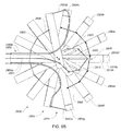
- There is a further need for enhanced methods and apparatus that allow a portion of a configurable device to assume a delivery or unexpanded configuration suitable for passage though a small bodily opening leading to a bodily cavity, and a deployed or expanded configuration suitable for positioning a plurality of transducer elements over a region extending across a majority of an interior tissue surface of the cavity. In particular, there is a need for enhanced methods and apparatus to arrange a plurality of transducer elements in a two- or three-dimensional grid or array capable of mapping, ablating, and or stimulating an inside surface of a bodily cavity or lumen without requiring mechanical scanning.
-
US5465717 describes an apparatus for mapping a wall of a heart forming a chamber in the heart comprising a guiding catheter having a lumen extending therethrough and a mapping catheter having a shaft that is slidably mounted in the lumen of the guiding catheter. A basket assembly is provided and is comprised of a plurality of circumferentially spaced-apart longitudinally extending arms having proximal and distal extremities. The proximal extremities of the arms are secured to the distal extremity of the shaft of the mapping catheter. Each of the arms includes a member formed of a material having a recoverable strain in excess of 1% and has an outwardly bowed shape memory. At least one electrode is provided on each of the arms. Conductors connected to the electrodes are carried by the arms. - Accordingly the present teaching provides a medical system per the appended claims.
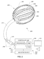
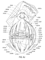
- The present design of a medical device with enhanced capabilities for deployment, positioning and ablating within a bodily cavity such as an intra-cardiac cavity is disclosed. In particular, the device is configurable from a first or unexpanded configuration in which a portion of the device is sized for delivery to a bodily cavity via a catheter sheath to a second or expanded configuration in which the portion of the device is expanded to position various transducer elements at least proximate a tissue surface within the bodily cavity. The device may employ a method for distinguishing tissue from blood and may be used to deliver positional information of the device relative to ports in the atrium, such as the pulmonary veins and mitral valve. The device may employ characteristics such as blood flow detection, impedance change detection or deflection force detection to discriminate between blood and tissue. The device may also improve ablation positioning and performance by ablating using the same elements used for discriminating between blood and tissue. Other advantages will become apparent from the teaching herein to those of skill in the art.
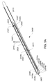
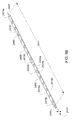
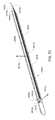
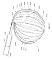
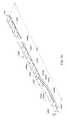
- A medical system may be summarized as including a device that includes a plurality of elongate members, each elongate member in the plurality of elongate members including a first end and a second end, an intermediate portion positioned between the first end and the second end, and a respective length between the first end and the second end. A portion of the device is selectively moveable between an unexpanded configuration in which at least the respective intermediate portions of the elongate members of the plurality of elongate members are arranged successively with respect to one another along a first direction in a stacked arrangement, the stacked arrangement sized to be delivered through a bodily opening leading to a bodily cavity, and an expanded configuration in which each of at least some of the plurality of elongate members are fanned about each of one or more axes. When the portion of the device is in the expanded configuration, at least one elongate member of the plurality of elongate members is arranged such that the one or more axes pass through the at least one elongate member of the plurality of elongate members at two or more locations, each location of the two or more locations spaced from another location of the two or more locations along the respective length of the at least one elongate member of the plurality of elongate members.
- The one or more axes may include two or more axes, and the at least one elongate member of the plurality of elongate members may be arranged such that each axis of the two or more axes passes through a respective one of the two or more locations when the portion of the device is in the expanded configuration. At least a first axis of the two or more axes may be collinear with a second axis of the two or more axes when the portion of the device is in the expanded configuration. Each elongate member of the at least some of the plurality of elongate members may cross the at least one elongate member of the plurality of elongate members in an X configuration about at least one axis of the one or more axes when the portion of the device is in the expanded configuration.
- The device may include at least one coupler arranged to physically couple each elongate member of the at least some of the plurality of elongate members together with the at least one elongate member of the plurality of elongate members. The at least one coupler may include a plurality of the couplers, each coupler of the plurality of the couplers spaced from at least one other one of the plurality of the couplers along the respective length of the at least one elongate member of the plurality of elongate members. The at least one coupler may include a flexible line arranged to be received in at least one opening provided in the at least one elongate member of the plurality of elongate members.
- The at least one elongate member of the plurality of elongate members may be twisted about a twist axis extending along a portion of the respective length of the at least one elongate member of the plurality of elongate members. The two or more locations may include at least three locations.
- Various systems may include combinations and subsets of those summarized above.
- A medical system may be summarized as including a structure that includes a plurality of elongate members. Each elongate member of the plurality of elongate members includes a proximal end, a distal end, an intermediate portion positioned between the proximal end and the distal end, and a thickness. Each intermediate portion includes a front surface and a back surface opposite across the thickness of the elongate member from the front surface. The structure is selectively moveable between an unexpanded configuration in which at least the respective intermediate portions of the elongate members of the plurality of elongate members are arranged with respect to one another front surface-toward-back surface in a stacked array sized for delivery through a bodily opening leading to a bodily cavity, and an expanded configuration in which the respective intermediate portions of at least some of the plurality of elongate members are angularly spaced with respect to one another about a first axis. Each of the at least some of the plurality of elongate members further includes a curved portion arranged to extend along at least a portion of a respective curved path that intersects the first axis at each of a respective at least two spaced apart locations along the first axis when the structure is in the expanded configuration.
- In some embodiments each elongate member of the plurality of elongate members includes a respective length between the proximal end and the distal end, and at least a first elongate member of the at least some of the plurality of elongate members crosses a second elongate member of the at least some of the plurality of elongate members at a location along the respective length of the second elongate member of the at least some of the plurality of elongate members when the structure is in the expanded configuration. At least a first elongate member of the at least some of the plurality of elongate members may cross a second elongate member of the at least some of the plurality of elongate members in an X configuration at each of at least one of the respective at least two spaced apart locations along the first axis intersected by the at least a portion of the respective curved path extended along by the curved portion of the second elongate member of the at least some of the plurality of elongate members when the structure is in the expanded configuration.
- The device may include at least one coupler arranged to physically couple each elongate member of the at least some of the plurality of elongate members together with at least one other elongate member of the plurality of elongate members. In some embodiments each elongate member of the plurality of elongate members includes a respective length between the proximal end and the distal end, and the at least one coupler includes a plurality of couplers, each coupler of the plurality of couplers spaced from another coupler of the plurality of couplers along the respective length of the at least one other elongate member of the plurality of elongate members. At least one of the respective at least two spaced apart locations along the first axis intersected by at least the portion of the respective curved path extended along by the curved portion of at least a first elongate member of the at least some of the plurality of elongate members may be positioned between a first coupler of the plurality of couplers and at least a second coupler of the plurality of couplers when the structure is in the expanded configuration.
- In some embodiments each elongate member of the plurality of elongate members includes a respective length between the proximal end and the distal end, and at least one elongate member of the plurality of elongate members is twisted about a twist axis extending along a portion of the respective length of the at least one elongate member of the plurality of elongate members. The respective at least two spaced apart locations along the first axis intersected by at least the portion of the respective curved path extended along by the curved portion of at least a first one of the at least some of the plurality of elongate members when the structure is in the expanded configuration may include at least three spaced apart locations along the first axis.
- Various systems may include combinations and subsets of those summarized above.
- A medical system may be summarized as including a device that includes a plurality of elongate members and at least a first coupler arranged to physically couple each elongate member of the plurality of elongate members together with each other of the elongate members of the plurality of elongate members. Each elongate member of the plurality of elongate members includes a proximal end, a distal end, an intermediate portion positioned between the proximal end and the distal end, a respective length between the proximal end and the distal end, and a thickness. Each intermediate portion includes a front surface and a back surface opposite across the thickness of the elongate member from the front surface. A portion of the device is selectively moveable between an unexpanded configuration in which at least the respective intermediate portions of the elongate members of the plurality of elongate members are arranged with respect to each other front surface-toward-back surface in a stacked array sized for delivery through a bodily opening leading to a bodily cavity, each elongate member of the plurality of elongate members arranged to be advanced distal end first into the bodily cavity, and an expanded configuration in which at least a first elongate member of the plurality of elongate members is positioned to cross a second elongate member of the plurality of elongate members in an X configuration at a first location spaced along the respective length of the second elongate member from a location of at least the first coupler. The first location may be positioned between at least the first coupler and the respective distal end of the second elongate member. The first location may be spaced from the respective distal end of the second elongate member.
- At least the first elongate member of the plurality of elongate members may be positioned to cross the second elongate member of the plurality of elongate members in an X configuration at a second location spaced from the first location along the respective length of the second elongate member of the plurality of elongate members when the portion of the device is in the expanded configuration. The medical system may further include a second coupler arranged to physically couple each elongate member of the plurality of elongate members together with each other of the elongate members of the plurality of elongate members. The first location may be spaced along the respective length of the second elongate member from a location of the second coupler and the first location may be positioned between at least the first coupler and the second coupler when the portion of the device is in the expanded configuration.
- The respective intermediate portions of each of at least some of the plurality of elongate members may be angularly spaced, like lines of longitude, with respect to one another about a first axis extending through the first location when the portion of the device is in the expanded configuration. At least one elongate member of the plurality of elongate members may be twisted about an axis extending along a portion of the respective length of the at least one elongate member of the plurality of elongate members.
- Various systems may include combinations and subsets of those summarized above.
- A medical system may be summarized as including a structure that includes a plurality of elongate members. Each elongate member of the plurality of elongate members includes a proximal end, a distal end, an intermediate portion positioned between the proximal end and the distal end, a respective length between the proximal end and the distal end, and a thickness. Each intermediate portion includes a front surface and a back surface opposite across the thickness of the elongate member from the front surface. Each intermediate portion further includes a respective pair of side edges that define a portion of a periphery of at least one of the front surface and the back surface, the side edges of each pair of side edges opposed to one another across at least a portion of the length of the respective elongate member. The structure is selectively moveable between an unexpanded configuration in which at least the respective intermediate portions of the elongate members of the plurality of elongate members are arranged with respect to one another front surface-toward-back surface in a stacked array sized for delivery through a bodily opening leading to a bodily cavity, and an expanded configuration in which the structure is sized too large for delivery through the bodily opening leading to the bodily cavity. At least a first elongate member of the plurality of elongate members is positioned such that one of the side edges of the pair of side edges of the first elongate member crosses one of the side edges of the pair of side edges of a second elongate member of the plurality of elongate members at each of a plurality of spaced apart locations along the respective length of the second elongate member as viewed normally to each of a respective one of a plurality of portions of the front surface of the respective intermediate portion of the second elongate member over which each of the plurality of spaced apart locations along the respective length of the second elongate member is positioned when the structure is in the expanded configuration.
- The respective intermediate portions of at least some of the plurality of elongate members may be fanned with respect to one another about an axis when the structure is in the expanded configuration. At least some of the plurality of elongate members may be fanned with respect to the second elongate member about one or more axes when the structure is in the expanded configuration, the second elongate member arranged such that the one or more axes passes through the second elongate member at each of two or more locations, each location of the two or more locations spaced from another location of the two or more locations along the respective length of the second elongate member. The plurality of spaced apart locations along the respective length of the second elongate member may include at least three spaced apart locations along the respective length of the second elongate member.
- The device may further include at least one coupler arranged to physically couple at least some of the plurality of elongate members together with the second elongate member, the at least one coupler spaced along the respective length of the second elongate member from at least one of the plurality of spaced apart locations along the respective length of the second elongate member when the structure is in the expanded configuration. The at least one coupler may be positioned along the respective length of the second elongate member relatively closer to one of the respective proximal end and the respective distal end of the second elongate member than each of at least two of the plurality of spaced apart locations along the respective length of the second elongate member when the structure is in the expanded configuration. Each elongate member of the plurality of elongate members may be arranged to be advanced distal end first into the bodily cavity when the structure is in the unexpanded configuration, and the at least one coupler may be positioned along the respective length of the second elongate member relatively closer to the respective distal end of the second elongate member than at least one of the plurality of spaced apart locations along the respective length of the second elongate member when the structure is in the expanded configuration.
- At least one elongate member of the plurality of elongate members may be twisted about an axis extending along a portion of the respective length of the at least one elongate member of the plurality of elongate members. The back surface of the respective intermediate portion of at least the first elongate member may, or may not be separated from the front surface of the respective intermediate portion of the second elongate member at each of at least one of the plurality of spaced apart locations along the respective length of the second elongate member when the structure is in the expanded configuration.
- The one of the side edges of the pair of side edges of the first elongate member may be opposed to the one of the side edges of the pair of side edges of the second elongate member in the stacked array when the structure is in the unexpanded configuration. The first elongate member of the plurality of elongate members may be positioned such that the other one of the side edges of the pair of side edges of the first elongate member crosses the other one of the side edges of the pair of side edges of the second elongate member at each of one or more locations along the respective length of the second elongate member as viewed normally to each of a respective one of one or more portions of the front surface of the respective intermediate portion of the second elongate member over which each of the one or more locations along the respective length of the second elongate member is positioned when the structure is in the expanded configuration.
- Various systems may include combinations and subsets of those summarized above.
- A medical system may be summarized as including a structure that includes a plurality of elongate members and at least one coupler arranged to physically couple at least a first elongate member of the plurality of elongate members together with a second elongate member of the plurality of elongate members. Each elongate member of the plurality of elongate members includes a proximal end, a distal end, an intermediate portion positioned between the proximal end and the distal end, and a thickness. Each intermediate portion includes a front surface and a back surface opposite across the thickness of the elongate member from the front surface, a respective geodesic extending along a portion of each of the elongate members between a location at least proximate the proximal end and another location at least proximate the distal end of the elongate member. Each geodesic is located at least on the front surface of the respective intermediate portion of the elongate member. The structure is selectively moveable between an unexpanded configuration in which at least the respective intermediate portions of the elongate members of the plurality of elongate members are arranged with respect to one another front surface-toward-back surface in a stacked array sized for delivery through a bodily opening leading to a bodily cavity, each elongate member of the plurality of elongate members arranged to be advanced distal end first into the bodily cavity, and an expanded configuration in which the structure is sized too large for delivery through the bodily opening to the bodily cavity. At least the first elongate member is positioned such that the respective geodesic of the first elongate member crosses the respective geodesic of the second elongate member at a first location along the geodesic of the second elongate member as viewed normally to a respective portion of the front surface of the intermediate portion of the second elongate member over which the first location along the respective geodesic of the second elongate member is positioned. The first location is spaced from a location of the at least one coupler along the second elongate member, and the first location may be positioned between the at least one coupler and the respective distal end of the second elongate member when the structure is in the expanded configuration.
- The respective intermediate portions of at least some of the plurality of elongate members may be fanned with respect to one another about an axis when the structure is in the expanded configuration. At least some of the plurality of elongate members may be fanned with respect to the second elongate member about one or more axes when the structure is in the expanded configuration, the second elongate member curved such that the one or more axes pass through the second elongate member at each of two or more locations, each location of the two or more locations spaced from each other between the respective proximal and distal ends of the second elongate member. The respective intermediate portions of at least some of the plurality of elongate members may be angularly spaced with respect to one another about a first axis, like lines of longitude, when the structure is in the expanded configuration, each of the least some of the plurality of elongate members including a curved portion arranged to extend along at least a portion of a respective curved path that intersects the first axis at each of a respective at least two spaced apart locations along the first axis.
- At least one elongate member of the plurality of elongate members may be twisted about an axis extending along a portion of the at least one elongate member of the plurality of elongate members located between the respective proximal and distal ends of the at least one elongate member of the plurality of elongate members.
- The structure may include at least one other coupler arranged to physically couple at least the first elongate member together with the second elongate member, the at least one other coupler positioned relatively closer to the respective distal end of the second elongate member than the at least one coupler, and the first location may be positioned between the at least one coupler and the at least one other coupler along the second elongate member when the structure is in the expanded configuration.
- The structure may include at least one other coupler arranged to physically couple at least the first elongate member together with the second elongate member, the at least one other coupler spaced from the at least one coupler along the second elongate member, and the first location may be positioned along the second elongate member relatively closer to the respective distal end of the second elongate member than each of the at least one coupler and the at least one other coupler when the structure is in the expanded configuration.
- The at least one coupler may include a flexible line arranged to pass through an opening provided in each of at least one of the first elongate member and the second elongate member. The back surface of the respective intermediate portion of at least the first elongate member may contact the front surface of the respective intermediate portion of the second elongate member at the first location when the structure is in the expanded configuration. The back surface of the respective intermediate portion of at least the first elongate member may be separated from the front surface of the respective intermediate portion of the second elongate member at the first location when the structure is in the expanded configuration.
- Various systems may include combinations and subsets of those summarized above.
- A medical system may be summarized as including a structure that includes a plurality of elongate members, each elongate member of the plurality of elongate members including a proximal end, a distal end, and a respective intermediate portion positioned between the proximal end and the distal end. The structure is selectively moveable between a delivery configuration in which the structure is suitably sized to allow the structure to be intravascularly or percutaneously delivered to a bodily cavity, and a deployed configuration in which the structure is expanded to have a size too large to allow the structure to be intravascularly or percutaneously delivered to the bodily cavity. The plurality of elongate members include a first set of the elongate members and a second set of the elongate members, at least the respective intermediate portions of the elongate members in each of the first and the second sets of the elongate members pivoting about at least one axis when the structure is moved into the deployed configuration, each of the respective intermediate portions of the elongate members in the first set of the elongate members pivoting along a first angular direction and each of the respective intermediate portions of the elongate members in the second set of the elongate members pivoting along a second angular direction opposite to the first angular direction. At least the respective intermediate portion of at least one of the elongate members in the first set of the elongate members is positioned between the respective intermediate portions of at least two of the elongate members in the second set of the elongate members when the structure is in the delivery configuration.
- In some embodiments each elongate member of the plurality of elongate members includes a thickness, and the respective intermediate portion of each elongate member of the plurality of elongate members includes a front surface and a back surface opposite across the thickness of the elongate member from the front surface. At least one portion of the respective front surface of each elongate member of the plurality of elongate members may be positioned to directly face an interior tissue surface of the bodily cavity when the structure is moved into the deployed configuration within the bodily cavity, and the respective front surface of the at least one of the elongate members in the first set of the elongate members may be positioned to directly face the respective back surface of one of the at least two of the elongate members in the second set of the elongate members when the structure is in the delivery configuration. The respective intermediate portions of the elongate members of the plurality of elongate members may be arranged with respect to one another front surface-toward-back surface in a stacked array when the structure is in the delivery configuration. At least the respective intermediate portions of the elongate members in the first set of the elongate members may be interleaved with at least the respective intermediate portions of the elongate members in the second set of the elongate members in a stacked array when the structure is in the delivery configuration.
- In some embodiments each elongate member of the plurality of elongate members includes a respective length between the respective proximal and distal ends of the elongate member, and at least a first elongate member of the plurality of elongate members crosses a second elongate member of the plurality of elongate members in an X configuration at each of at least one location along the respective length of the second elongate member of the plurality of elongate members when the structure is in the deployed configuration.
- In some embodiments each elongate member of the plurality of elongate members includes a respective length between the respective proximal and distal ends of the elongate member, and at least one elongate member of the plurality of elongate members is arranged such that the at least one axis passes through the at least one elongate member of the plurality of elongate members at each of two or more locations, each location of the two or more locations spaced from another location of the two or more locations along the respective length of the at least one elongate member of the plurality of elongate members when the structure is in the deployed configuration. The two or more locations may include at least three spaced apart locations along the respective length of the at least one elongate member of the plurality of elongate members.
- Various systems may include combinations and subsets of those summarized above.
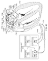
- A medical system may be summarized as including at least one transducer controller; and a device that includes a plurality of transducer elements and a plurality of flexible circuit structures. Each of the flexible circuit structures includes at least one flexible substrate and a set of one or more electrical conductors carried by the at least one flexible substrate, at least some the electrical conductors in the set of one or more electrical conductors providing at least a portion of a signal path between the at least one transducer controller and at least some of the transducer elements. At least one portion of each of the plurality of flexible circuit structures is positionable within a bodily cavity. A portion of the device is selectively moveable between an unexpanded configuration in which at least the respective at least one portions of the plurality of flexible circuit structures are arranged successively along a first direction in a stacked arrangement, the stacked arrangement sized to be intravascularly or percutaneously delivered through a bodily opening leading to the bodily cavity, and an expanded configuration in which the respective at least one portions of the plurality of flexible circuit structures are angularly spaced with respect to one another about at least one axis. The respective at least one portion of each of at least some of the flexible circuit structures may pivot about the least one axis when the portion of the device is moved between the unexpanded configuration and the expanded configuration.
- At least one of the plurality of flexible circuit structures may be arranged such that the at least one axis passes through the at least one of the plurality of flexible circuit structures at each of two or more spaced apart locations when the portion of the device is in the expanded configuration. The two or more spaced apart locations may include at least three spaced apart locations. At least a first one of the plurality of flexible circuit structures may cross a second one of the plurality of flexible circuit structures in an X configuration when the portion of the device is in the expanded configuration.
- The respective at least one flexible substrate of each of at least some of the plurality of flexible circuit structures may include a plurality of material layers, at least one of the material layers bonded to at least one other of the material layers with an adhesive. The respective at least one portion of at least one of the plurality of flexible circuit structures may include a different number of material layers than at least another portion of the at least one of the plurality of flexible circuit structures. At least one of the plurality of transducer elements may be carried by the respective at least one portion of each of the at least some of the plurality of flexible circuit structures. Each of the plurality of flexible circuit structures may be a printed flexible circuit structure. At least one of the plurality of flexible circuit structures includes a twist about a twist axis.
- Various systems may include combinations and subsets of those summarized above.
- A medical system may be summarized as including a device that includes a plurality of elongate members. Each elongate member of the plurality of elongate members includes a first end, a second end, an intermediate portion positioned between the first end and the second end, and a thickness. Each intermediate portion includes a front surface and a back surface opposite across the thickness of the elongate member from the front surface. A portion of the device is selectively moveable between a delivery configuration in which at least the respective intermediate portions of the elongate members of the plurality of elongate members are arranged with respect to one another front surface-toward-back surface in a stacked array sized for delivery through a bodily opening leading to a bodily cavity, and a deployed configuration in which at least the respective intermediate portion of each elongate member of at least some of the plurality of elongate members is arranged within the bodily cavity to position a first portion of the front surface of the respective intermediate portion of the elongate member of the at least some of the plurality of elongate members to face a first portion of an interior tissue surface within the bodily cavity and to position a second portion of the front surface of the respective intermediate portion of the elongate member of the at least some of the plurality of elongate members to face a second portion of the interior tissue surface, where the second portion of the interior tissue surface is opposed across the bodily cavity from the first portion of the interior tissue surface.
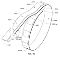
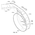
- The at least some of the plurality of elongate members may be bent about a bending axis into an arcuate stacked array when the portion of the device is in the deployed configuration.
- At least the respective intermediate portions of the elongate members of the at least some of the plurality of elongate members may be fanned with respect to at least one elongate member of the plurality of elongate members about each of one or more axes when the portion of the device is in the deployed configuration. In some embodiments each elongate member of the plurality of elongate members includes a respective length between the respective first end and the respective second end of the elongate member, and the one or more axes pass through the at least one elongate member of the plurality of elongate members at two or more locations when the portion of the device is in the deployed configuration, each location of the two or more locations spaced from another location of the two or more locations along the respective length of the at least one elongate member of the plurality of elongate members. The two or more locations may include at least three spaced apart locations along the respective length of the at least one elongate member of the plurality of elongate members.
- In some embodiments each elongate member of the plurality of elongate members includes a respective length between the respective first end and the respective second end of the elongate member, and at least a first elongate member of the at least some of the plurality of elongate members crosses a second elongate member of the at least some of the plurality of elongate members in an X configuration at each of one or more locations along the respective length of the second elongate member of the at least some of the plurality of elongate members when the portion of the device is in the deployed configuration. At least one location of the one or more locations may be spaced along the respective length of the second elongate member of the at least some of the plurality of elongate members from each of the respective first end and the respective second end of the second elongate member. The at least one location of the one or more locations may be located along the respective length of the second elongate member of the at least some of the plurality of elongate members between the respective first and second portions of the front surface of the respective intermediate portion of the second elongate member of the at least some of the plurality of elongate members. The one or more locations along the respective length of the second elongate member of the at least some of the plurality of elongate members may include at least two spaced apart locations along the respective length of the second elongate member of the at least some of the plurality of elongate members. The device may further include at least one coupler that physically couples at least the first and the second elongate members of the at least some of the plurality of elongate members together. The at least one location of the one or more locations may be spaced along the respective length of the second elongate member of the at least some of the plurality of elongate members from a location of the at least one coupler when the portion of the device is in the deployed configuration. The device may further include a plurality of couplers which each physically couples at least the second elongate member of the at least some of the plurality of elongate members together with at least one other elongate member of the plurality of elongate members, each coupler of the plurality of couplers spaced from another of the plurality of couplers along the respective length of the second elongate member of the at least some of the plurality of elongate members. The at least one location of the one or more locations may be located along the respective length of the second elongate member of the at least some of the plurality of elongate members between the respective locations of at least two of the plurality of couplers when the portion of the device is in the deployed configuration. The at least one location of the one or more locations may be located along the respective length of the second elongate member of the at least some of the plurality of elongate members relatively closer to the respective first end of the second elongate member than a respective location of each of at least two of the plurality of couplers when the portion of the device is in the deployed configuration, the respective first end of each elongate member of the plurality of elongate members arranged to be advanced into the bodily cavity before the respective second end of the elongate member of the plurality of elongate members when the portion of the device is in the delivery configuration.
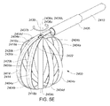
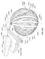
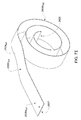
- Each elongate member of the at least some of the plurality of elongate members may have a volute shape profile when the portion of the device is in the deployed configuration.
- Each of the first and the second portions of the front surface of the respective intermediate portion of the elongate member of the at least some of the plurality of elongate members may include respective ones of one or more transducers which face a respective one of a pair of diametrically opposed portions of the interior tissue surface within the bodily cavity when the portion of the device is in the deployed configuration in use.
- Various systems may include combinations and subsets of those summarized above.
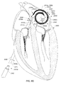
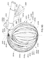
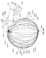
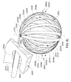
- A medical system may be summarized as including a structure that includes a plurality of elongate members. Each elongate member of the plurality of elongate members includes a proximal end, a distal end, and a respective intermediate portion positioned between the proximal end and the distal end. The structure is selectively moveable between a delivery configuration in which the structure is suitably sized to be intravascularly or percutaneously delivered to a bodily cavity, and a deployed configuration in which the structure has a size too large to be intravascularly or percutaneously delivered to the bodily cavity. The respective intermediate portions of at least two of the plurality of elongate members are angularly spaced with respect to one another about a first axis, similar to lines of longitude, and each of the at least two of the plurality of elongate members includes a curved portion that extends along at least a portion of a respective curved path that intersects the first axis at each of a respective at least two spaced apart locations along the first axis when the structure is in the deployed configuration. The medical system further includes a handle portion, and a shaft member. A portion of the shaft member sized and arranged to deliver the structure intravascularly or percutaneously to the bodily cavity. The shaft member includes a first end positioned at least proximate to the handle portion and a second end physically coupled to the structure at one or more locations on the structure. Each of the one or more locations on the structure to which the second end is physically coupled is positioned to one side of at least one spatial plane coincident with the first axis when the structure is in the deployed configuration.
- At least one of the one or more locations on the structure to which the second end is physically coupled may be at least proximate to the respective proximal ends of at least some of the plurality of elongate members. Each of the at least two of the plurality of elongate members may extend tangentially from the second end of the shaft member when the structure is in the deployed configuration. Each of the proximal ends of the elongate members of the plurality of elongate members may be positioned to one side of the at least one spatial plane coincident with the first axis when the structure is in the deployed configuration. Each of the distal ends of the elongate members of the plurality of elongate members may be positioned to one side of the at least one spatial plane coincident with the first axis when the structure is in the deployed configuration. The shaft member may be arranged to avoid intersection by the first axis when the structure is in the deployed configuration. The shaft member may be arranged to avoid intersection of the second end of the shaft member by the first axis when the structure is in the deployed configuration.
- The respective intermediate portion of each elongate member of the plurality of elongate members may include a front surface and a back surface opposite across a thickness of the elongate member from the front surface, and at least the respective intermediate portions of the elongate members of the plurality of elongate members may be arranged with respect to one another front surface-toward-back surface in a stacked array when the structure is in the delivery configuration.
- In some embodiments each elongate member of the plurality of elongate members includes a respective length between the respective proximal end and the respective distal end of the elongate member, and the first axis passes through each of at least one elongate member of the plurality of elongate members at two or more locations when the structure is in the deployed configuration, each location of the two or more locations spaced from another location of the two or more locations along the respective length of the at least one elongate member of the plurality of elongate members. The two or more locations may include at least three locations spaced along the respective length of the at least one elongate member of the plurality of elongate members.
- In some embodiments each elongate member of the plurality of elongate members includes a respective length between the respective proximal end and the respective distal end of the elongate member, and at least a first elongate member of the plurality of elongate members crosses a second elongate member of the plurality of elongate member in an X configuration at a location along the respective length of the second elongate member spaced from each of the respective proximal end and the respective distal end of the second elongate member when the structure is in the deployed configuration. Each elongate member of at least some of the plurality of elongate members may have a volute shape profile when the structure is in the deployed configuration.
- Various systems may include combinations and subsets of those summarized above.
- A medical system may be summarized as including a device that includes a plurality of elongate members. Each elongate member of the plurality of elongate members includes a proximal end, a distal end, an intermediate portion positioned between the proximal end and the distal end, and a thickness. Each intermediate portion includes a front surface and a back surface opposite across the thickness of the elongate member from the front surface. A portion of the device is selectively moveable between a delivery configuration in which at least the respective intermediate portions of the elongate members of the plurality of elongate members are arranged with respect to one another front surface-toward-back surface in a stacked array sized for delivery through a bodily opening leading to a bodily cavity, and a deployed configuration in which the respective intermediate portion of each elongate member of at least some of the plurality of elongate members has a volute shape profile.
- At least the respective intermediate portions of the elongate members of the at least some of the plurality of elongate members may be fanned with respect to at least one elongate member of the plurality of elongate members about at least one axis when the portion of the device is in the deployed configuration. In some embodiments each elongate member of the plurality of elongate members includes a respective length between the respective proximal end and the respective distal end of the elongate member, and the at least one axis passes through the at least one elongate member of the plurality of elongate members at two or more locations when the portion of the device is in the deployed configuration, each location of the two or more locations spaced from another location of the two or more locations along the respective length of the at least one elongate member of the plurality of elongate members. The two or more locations may include at least three spaced apart locations along the respective length of the at least one elongate member of the plurality of elongate members.
- In some embodiments each elongate member of the plurality of elongate members includes a respective length between the respective proximal end and the respective distal end of the elongate member, and at least a first elongate member of the plurality of elongate members crosses a second elongate member of the plurality of elongate member in an X configuration at each of one or more locations along the respective length of the second elongate member spaced from each of the respective proximal end and the respective distal end of the second elongate member when the portion of the device is in the deployed configuration. The device may further include a plurality of couplers which each physically couples at least the second elongate member of the plurality of elongate members together with at least one other elongate member of the plurality of elongate members, each coupler of the plurality of couplers spaced from another of the plurality of couplers along the respective length of the second elongate member of the plurality of elongate members. At least one location of the one or more locations may be located along the respective length of the second elongate member of the plurality of elongate members between the respective locations of at least two of the plurality of couplers when the portion of the device is in the deployed configuration. Each elongate member of the plurality of elongate members in the stacked array may be arranged to be advanced distal end first into the bodily cavity when the portion of the device is in the delivery configuration, and at least one location of the one or more locations may be located along the respective length of the second elongate member of the plurality of elongate members relatively closer to the respective distal end of the second elongate member than a respective location of each of at least two of the plurality of couplers when the portion of the device is in the deployed configuration.
- Various systems may include combinations and subsets of those summarized above.
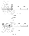
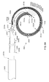
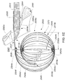
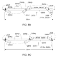
- A medical system may be summarized as including a catheter sheath that includes a first end, a second end and a lumen therebetween. The medical system further includes a device that includes a plurality of elongate members. Each elongate member of the plurality of elongate members includes a proximal end, a distal end, an intermediate portion positioned between the proximal end and the distal end, and a thickness. Each intermediate portion includes a front surface and a back surface opposite across the thickness of the elongate member from the front surface. A portion of the device is selectively moveable between a first configuration in which at least the respective intermediate portions of the elongate members of the plurality of elongate members are arranged with respect to one another front surface-toward-back surface in a stacked array sized for delivery through the lumen of the catheter sheath, each elongate member of the plurality of elongate members arranged to be advanced distal end first out from the lumen of the catheter sheath, and a second configuration in which the respective distal end of each of at least some of the plurality of elongate members moves along a respective coiled path as the elongate members advance out of the lumen of the catheter sheath, the respective intermediate portions of each elongate member of the at least some of the plurality of elongate members bent about a respective bending axis into an arcuate stacked array sized too large for delivery though the lumen of the catheter sheath.
- At least part of the coiled path may extend along a volute path. At least the respective intermediate portion of each elongate member of the at least some of the plurality of elongate members may have a volute shape profile when the portion of the device is in the second configuration.
- In some embodiments each elongate member of the plurality of elongate members includes a respective length between the respective proximal end and the respective distal end of the elongate member, and the portion of the device is further selectively moveable between at least the second configuration and a third configuration in which at least the respective intermediate portions of the elongate members of the at least some of the plurality of elongate members are fanned with respect to at least one elongate member of the plurality of elongate members about each of one or more axes. The one or more axes may pass through the at least one elongate member of the plurality of elongate members at two or more locations when the portion of the device is in the third configuration, each location of the two or more locations spaced from another location of the two or more locations along the respective length of the at least one elongate member of the plurality of elongate members. The two or more locations may include at least three spaced apart locations along the respective length of the at least one elongate member of the plurality of elongate members.
- In some embodiments each elongate member of the plurality of elongate members includes a respective length between the respective proximal end and the respective distal end of the elongate member, and the portion of the device is further selectively moveable between at least the second configuration and a third configuration in which at least a first elongate member of the plurality of elongate members crosses a second elongate member of the plurality of elongate members in an X configuration at each of one or more locations along the respective length of the second elongate member spaced from each of the respective proximal end and the respective distal end of the second elongate member. The device may further include a plurality of couplers which each physically couples at least the second elongate member of the plurality of elongate members together with at least one other elongate member of the plurality of elongate members, each coupler of the plurality of couplers spaced from another of the plurality of couplers along the respective length of the second elongate member. At least one location of the one or more locations may be located along the respective length of the second elongate member between the respective locations of at least two of the plurality of couplers when the portion of the device is in the third configuration. At least one location of the one or more locations may be located along the respective length of the second elongate member relatively closer to the respective distal end of the second elongate member than a respective location of each of at least two of the plurality of couplers when the portion of the device is in the third configuration.
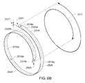
- At least one elongate member of the at least some of the plurality of elongate members may have an annular shape profile in the second configuration, the annular profile interrupted by a separation. The respective intermediate portion of each elongate member of the at least some of the plurality of elongate members may be preformed to autonomously bend about the respective bending axis of the elongate member of the at least some of the plurality of elongate members as the respective intermediate portion is advanced out from the lumen of the catheter sheath. The medical system may further include a bending unit that acts on at least one of the plurality of elongate members to bend the respective intermediate portion of each elongate member of the at least some of the plurality of elongate members about the respective bending axis of the elongate member of the at least some of the plurality of elongate members when the portion of the device is moved between the first configuration and the second configuration.
- Various systems may include combinations and subsets of those summarized above.
- A medical system may be summarized as including a device that includes a plurality of elongate members. Each elongate member of the plurality of elongate members includes a first end and a second end, an intermediate portion between the first end and the second end, and a respective length between the first end and the second end. The device further includes a plurality of couplers that includes a proximal coupler, a distal coupler and at least one intermediate coupler. Each coupler of the plurality of couplers is spaced from another of the plurality of couplers along the respective length of at least a first elongate member of the plurality of elongate members with the at least one intermediate coupler positioned between the proximal coupler and the distal coupler. Each coupler of the plurality of couplers is arranged to couple at least the first elongate member together with least one other elongate member of the plurality of elongate members. A portion of the device is selectively moveable between an unexpanded configuration in which at least the respective intermediate portions of the elongate members of the plurality of elongate members are sized and arranged to be delivered through a bodily opening leading to a bodily cavity within a body, the bodily cavity having an interior tissue surface interrupted by a port of the bodily opening, and the plurality of couplers arranged to be advanced distal coupler first into the bodily cavity, and an expanded configuration in which at least the respective intermediate portions of at least some of the plurality of elongate members are arranged such that at least the distal coupler is located within the bodily cavity at a respective location positioned relatively closer to the port of the bodily opening than a respective location of the at least one intermediate coupler within the bodily cavity.
- When the portion of the device is in the expanded configuration, the proximal coupler may be positioned relatively closer to the port of the bodily opening than the distal coupler within the bodily cavity. When the portion of the device is in the expanded configuration, the distal coupler may be positioned relatively closer to the port of the bodily opening than the proximal coupler. At least the respective intermediate portions of the at least some of the plurality of elongate members may be arranged such that the proximal coupler is located within the body at a location outside of the bodily cavity when the portion of the device is in the expanded configuration.
- At least the respective intermediate portions of the elongate members of the plurality of elongate members may be arranged successively with respect to one another along a first direction in a stacked arrangement when the portion of the device is in the unexpanded configuration.
- The respective intermediate portion of each elongate member of the plurality of elongate members may include a thickness, a front surface and a back surface opposite across the thickness from the front surface. At least the respective intermediate portions of the elongate members of the plurality of elongate members may be arranged with respect to one another front surface-toward-back surface in a stacked array sized for delivery through the bodily opening leading to the bodily cavity when the portion of the device is in the unexpanded configuration, and the respective intermediate portion of each elongate member of the at least some of the plurality of elongate members may be bent about a respective bending axis when the portion of the device is in the expanded configuration. The respective intermediate portion of each elongate member of the at least some of the plurality of elongate members may be preformed to autonomously bend about the respective bending axis of the elongate member of the at least some of the plurality of elongate members when the respective intermediate portion of the elongate member of the at least some of the plurality of elongate members is advanced into the bodily cavity.
- At least the respective intermediate portions of the elongate members of the at least some of the plurality of elongate members may be fanned with respect to at least one elongate member of the plurality of elongate members about each of one or more axes, and the one or more axes may pass through the at least one elongate member of the plurality of elongate members at two or more locations when the portion of the device is in the expanded configuration. Each location of the two or more locations may be spaced from another location of the two or more locations along the respective length of the at least one elongate member of the plurality of elongate members. The two or more locations may include at least three spaced apart locations along the respective length of the at least one elongate member of the plurality of elongate members. At least a second elongate member of the plurality of elongate members may cross the first elongate member at a location along the respective length of the first elongate member spaced from each of the proximal coupler and the distal coupler when the portion of the device is in the expanded configuration.
- Various systems may include combinations and subsets of those summarized above.
- A medical system may be summarized as including a device that includes a plurality of elongate members. Each elongate member of the plurality of elongate members includes a proximal end, a distal end, an intermediate portion positioned between the proximal end and the distal end, and a thickness. Each intermediate portion includes a front surface and a back surface opposite across the thickness of the elongate member from the front surface. A respective geodesic defined for each elongate member extends along the respective elongate member between a first location at least proximate the proximal end and a second location at least proximate the distal end of the elongate member, each geodesic defined at least on the front surface of the respective intermediate portion of the elongate member. A portion of the device is selectively moveable between an unexpanded configuration in which at least the respective intermediate portions of the elongate members of the plurality of elongate members are arranged front surface-toward-back surface in a stacked array sized to be delivered through a bodily opening leading to a bodily cavity having an interior tissue surface interrupted by a port of the bodily opening, each elongate member of the plurality of elongate members arranged to be advanced distal end first into the bodily cavity, and an expanded configuration in which at least a first elongate member of the plurality of elongate members is positioned to cross a second elongate member of the plurality of elongate members at each of one or more crossing locations within the bodily cavity. Each of the one or more crossing locations is located on the front surface of the second elongate member at a respective one of one or more locations along the respective geodesic of the second elongate member that is crossed by the respective geodesic of the first elongate member as viewed normally to a respective one of one or more portions of the front surface of the second elongate member over which each respective one of the one or more locations along the respective geodesic of the second elongate member is located. The elongate members of the plurality of elongate members are arranged such that the respective distal end of each elongate member of at least some of the plurality of elongate members is positioned within the bodily cavity at a respective location located relatively closer to the port of the bodily opening than at least one crossing location of the one or more crossing locations within the bodily cavity when the portion of the device is in the expanded configuration.
- The one or more crossing locations within the bodily cavity may include at least one other crossing location, the least one other crossing location located within the bodily cavity relatively closer to the port of the bodily opening than the respective location within the bodily cavity of the respective distal end of each elongate member of the at least some of the plurality of elongate members when the portion of the device is moved between the unexpanded configuration and the expanded configuration.
- The respective intermediate portion of each elongate member of the at least some of the plurality of elongate members may be arranged within the bodily cavity to position a first portion of the front surface of the respective intermediate portion of the elongate member of the at least some of the plurality of elongate members to face a first portion of an interior tissue surface within the bodily cavity and to position a second portion of the front surface of the respective intermediate portion of the elongate member of the at least some of the plurality of elongate members to face a second portion of the interior tissue surface when the portion of the device is in the expanded configuration, the second portion of the interior tissue surface positioned diametrically opposite to the first portion of the interior tissue surface.
- The device may further include a plurality of couplers which each physically couples at least the second elongate member together with at least one other elongate member of the plurality of elongate members, each coupler of the plurality of couplers spaced from another coupler of the plurality of couplers along the second elongate member. The location of the at least one crossing location along the respective geodesic of the second elongate member may be positioned along the second elongate member between the respective locations of two of the plurality of couplers when the portion of the device is in the expanded configuration. The location of the at least one crossing location along the respective geodesic of the second elongate member may be located along the second elongate member relatively closer to the respective distal end of the second elongate member than a respective location of each of at least two of the plurality of couplers when the portion of the device is in the expanded configuration.
- The respective intermediate portion of each elongate member of the at least some of the plurality of elongate members may be preformed to autonomously bend about a respective bending axis as the respective intermediate portion of the elongate member of the at least some of the plurality of elongate members is advanced into the bodily cavity. The medical system may further include a bending unit that acts on at least one of the plurality of elongate members to bend each elongate member of the at least some of the plurality of elongate members about a respective bending axis within the bodily cavity when the portion of the device is moved between the unexpanded configuration and the expanded configuration.
- Various systems may include combinations and subsets of those summarized above.
- A medical system may be summarized as including a catheter sheath that includes a first end, a second end and a lumen therebetween. The medical system further includes a structure that includes a plurality of elongate members, each elongate member of the plurality of elongate members including a proximal end, a distal end, and an intermediate portion positioned between the proximal and the distal ends. The structure is selectively moveable between an unexpanded configuration in which the elongate members of the plurality of elongate members are arranged successively with respect to one another along a first direction in a stacked arrangement, the stacked arrangement sized to be delivered through the lumen of the catheter sheath from the first end of the catheter sheath towards the second end of the catheter sheath, a portion of at least one elongate member of the plurality of elongate members in the stacked arrangement positioned to be advanced from the second end of the catheter sheath prior to each of the other elongate members of the plurality of elongate members in the stacked arrangement as the stacked arrangement is delivered through the lumen of the catheter sheath from the first end of the catheter sheath towards the second end of the catheter sheath, and an expanded configuration in which the structure is expanded to have a size too large to be delivered through the lumen of the catheter sheath.
- In some embodiments each elongate member of the plurality of elongate members includes a respective length between the proximal and the distal ends of the elongate member, and the respective length of the at least one elongate member of the plurality of elongate members is longer than each of the respective lengths of the other elongate members of the plurality of elongate members. The portion of the at least one elongate member of the plurality of elongate members may be cantilevered from the stacked arrangement when the structure is in the unexpanded configuration. The at least one elongate member of the plurality of elongate members may include an outermost elongate member in the stacked arrangement when the structure is in the unexpanded configuration. The at least one elongate member of the plurality of elongate members may include an elongate member located between two outermost elongate members in the stacked arrangement when the structure is in the unexpanded configuration. The at least one elongate member of the plurality of elongate members may include at least two elongate members of the plurality of elongate members.
- In some embodiments each elongate member of the plurality of elongate members includes a respective length between the proximal and the distal ends of the elongate member, and at least a first elongate member of the plurality of elongate members crosses a second elongate member of the plurality of elongate members in an X configuration at each of one or more locations along the respective length of the second elongate member when the structure is in the expanded configuration, each of the one or more locations spaced from each of the respective proximal end and the respective distal end of the second elongate member.
- The respective intermediate portion of each elongate member of at least some of the plurality of elongate members may be preformed to autonomously bend about a respective bending axis as the respective intermediate portion of the elongate member of the at least some of the plurality of elongate members is advanced from the second end of the catheter sheath as the stacked arrangement is delivered through the lumen of the catheter sheath from the first end of the catheter sheath towards the second end of the catheter sheath. The medical system may further include a bending unit that acts on at least one of the plurality of elongate members to bend each elongate member of at least some of the plurality of elongate members about a respective bending axis when the respective intermediate portion of the elongate member of the at least some of the plurality of elongate members is advanced from the second end of the catheter sheath.
- Each elongate member of the plurality of elongate members may be arranged to be advanced distal end first as the stacked arrangement is delivered through the lumen of the catheter sheath from the first end of the catheter sheath towards the second end of the catheter sheath.
- Various systems may include combinations and subsets of those summarized above.
- A medical system may be summarized as including a structure that includes a plurality of elongate members. Each elongate member of the plurality of elongate members includes a proximal end, a distal end, a respective intermediate portion positioned between the proximal end and the distal end, and a respective length between the proximal and the distal ends. A method employing the medical system may be summarized as including intravascularly or percutaneously delivering at least a portion of the structure to a location within an intra-cardiac cavity formed at least in part by a tissue wall having an interior tissue surface, each elongate member of the plurality of elongate members introduced distal end first into the intra-cardiac cavity and the distal end of each elongate member of the plurality of elongate members curling away from the interior tissue surface as the distal end of the elongate member of the plurality of elongate members is advanced along a respective path within the intra-cardiac cavity during the intravascular or percutaneous delivery. The method further includes fanning at least some of the plurality of elongate members with respect to at least one elongate member of the plurality of elongate members about each of one or more axes within the intra-cardiac cavity. The one or more axes pass through the at least one elongate member of the plurality of elongate members at two or more locations, each location of the two or more locations spaced from another location of the two or more locations along the respective length of the at least one elongate member of the plurality of elongate members.
- In some embodiments the respective intermediate portion of each elongate member of the plurality of elongate members includes a front surface and a back surface opposite across a thickness of the elongate member from the front surface, and the method further includes positioning a first portion of the front surface of the respective intermediate portion of at least a first elongate member of the plurality of elongate members to face a first portion of the interior tissue surface and positioning a second portion of the front surface of the respective intermediate portion of at least the first elongate member of the plurality of elongate members to face a second portion of the interior tissue surface, the second portion of the interior tissue surface positioned diametrically opposite to the first portion of the interior tissue surface.
- In some embodiments, the respective intermediate portion of each elongate member of the plurality of elongate members may include a front surface and a back surface opposite across a thickness of the elongate member from the front surface, and at least the respective intermediate portions of the elongate members of the plurality of elongate members may be arranged with respect to one another front surface-toward-back surface in a stacked array when intravascularly or percutaneously delivering at least the portion of the structure to the location within the intra-cardiac cavity.
- The method may further include crossing a second elongate member of the plurality of elongate members with a first elongate member of the plurality of elongate members in an X configuration at each of one or more locations along the respective length of the second elongate member, each of the one or more locations spaced from each of the respective proximal end and the respective distal end of the second elongate member.
- Various methods may include combinations and subsets of those summarized above.
- A medical system may be summarized as including a structure that includes a plurality of elongate members. Each elongate member includes a first end, a second end, and an intermediate portion positioned between the first and the second ends. Each intermediate portion includes a thickness, a front surface and a back surface opposite across the thickness from the front surface. The structure further includes a proximal portion and a distal portion, each of the proximal and the distal portions of the structure including a respective part of each of at least some of the plurality of elongate members. The structure is selectively moveable between a delivery configuration in which the structure is sized for delivery through a bodily opening leading to a bodily cavity, at least the respective intermediate portions of the elongate members of the plurality of elongate members arranged front surface-toward-back surface in a stacked array when the structure is in the delivery configuration, and a deployed configuration in which the structure is sized too large for delivery through the bodily opening leading to the bodily cavity, the proximal portion of the structure forming a first domed shape and the distal portion of the structure forming a second domed shape when the structure is in the deployed configuration.
- At least one of the first domed shape and the second domed shape may have a first radius of curvature in a first spatial plane and a second radius of curvature in a second spatial plane that intersects the first spatial plane, a magnitude of the second radius of curvature different than a magnitude of the first radius of curvature.
- Each elongate member of the at least some of the plurality of elongate members may cross at least one other elongate member of the plurality of elongate members at least at one location between the proximal and the distal portions of the structure when the structure is in the deployed configuration.
- In some embodiments each elongate member of the plurality of elongate members includes a respective length between the first end and the second end of the elongate member, and each elongate member of the at least some of the plurality of elongate members crosses at least one other elongate member of the plurality of elongate members at each of a plurality of spaced apart locations along the respective length of at least the one other elongate member of the plurality of elongate members when the structure is in the deployed configuration. At least some of the plurality of elongate members may be fanned with respect to at least one of the plurality of elongate members about an axis passing through a location between the proximal and the distal portions of the structure when the structure is in the deployed configuration.
- In some embodiments, the medical system further includes at least one flexible line arranged to physically couple the proximal and the distal portions of the structure together, the at least one flexible line manipulable to vary a distance between the proximal and the distal portions of the structure when the structure is in the deployed configuration.
- Various systems may include combinations and subsets of those summarized above.
- A medical system may be summarized as including a structure that includes a plurality of elongate members. Each elongate member of the plurality of elongate members includes a proximal end, a distal end, and a respective intermediate portion positioned between the proximal end and the distal end. The structure is selectively moveable between a delivery configuration in which the structure is suitably sized to be intravascularly or percutaneously delivered to a bodily cavity, and a deployed configuration in which the structure is expanded to have a size too large to be intravascularly or percutaneously delivered to the bodily cavity. The respective intermediate portions of at least some of the plurality of elongate members are angularly spaced with respect to one another about a first axis, similar to lines of longitude, when the structure is in the deployed configuration. The medical system further includes a handle portion and a shaft member, a portion of the shaft member sized and arranged to deliver the structure intravascularly or percutaneously to the bodily cavity. The shaft member includes a first end positioned at least proximate to the handle portion and a second end physically coupled to the structure. In the deployed configuration the structure and the shaft member have a projected outline in the shape of the Greek letter rho, where a point where a loop of the letter would intersect a tail of the letter may be open or not closed. Such outline may be either without, or with, an opening defined by a loop portion of the letter represented.
- Each of the at least some of the plurality of elongate members may include a curved portion that extends along at least a portion of a respective curved path that intersects the first axis at each of a respective at least two spaced apart locations along the first axis when the structure is in the deployed configuration.
- In some embodiments the respective intermediate portion of each elongate member of the plurality of elongate members includes a front surface and a back surface opposite across a thickness of the elongate member, and at least the respective intermediate portions of the elongate members of the plurality of elongate members are arranged with respect to one another front surface-toward-back surface in a stacked array when the structure is in the delivery configuration.
- In some embodiments each elongate member of the plurality of elongate members includes a respective length between the respective proximal end and the respective distal end of the elongate member, and the first axis passes through each of at least one elongate member of the plurality of elongate members at two or more locations when the structure is in the deployed configuration, each location of the two or more locations spaced from another location of the two or more locations along the respective length of the at least one elongate member of the plurality of elongate members. The two or more locations may include at least three locations spaced along the respective length of the at least one elongate member of the plurality of elongate members.
- In some embodiments each elongate member of the plurality of elongate members includes a respective length between the respective proximal end and the respective distal end of the elongate member, and at least a first elongate member of the plurality of elongate members crosses a second elongate member of the plurality of elongate member in an X configuration at each of one or more locations along the respective length of the second elongate member spaced from each of the respective proximal end and the respective distal end of the second elongate member when the structure is in the deployed configuration. The medical system may further include a plurality of couplers which each physically couples at least the second elongate member of the plurality of elongate members together with at least one other elongate member of the plurality of elongate members, each coupler of the plurality of couplers spaced from another of the plurality of couplers along the respective length of the second elongate member of the plurality of elongate members. At least one location of the one or more locations may be located along the respective length of the second elongate member of the plurality of elongate members between the respective locations of at least two of the plurality of couplers when the structure is in the deployed configuration. Each elongate member of the plurality of elongate members may be arranged to be advanced distal end first into the bodily cavity when the structure is in the delivery configuration, and at least one location of the one or more locations may be located along the respective length of the second elongate member of the plurality of elongate members relatively closer to the respective distal end of the second elongate member than a respective location of each of at least two of the plurality of couplers when the structure is in the deployed configuration.
- Various systems may include combinations and subsets of those summarized above.
- A medical system may be summarized as including a structure that includes a proximal portion and a distal portion. The structure is selectively movable between a delivery configuration in which the structure is sized for delivery through a bodily opening leading to a bodily cavity, the structure arranged to be advanced distal portion first into the bodily cavity, and a deployed configuration in which the structure is sized too large for delivery through the bodily opening leading to the bodily cavity. The proximal portion of the structure forms a first domed shape and the distal portion of the structure forms a second domed shape when the structure is in the deployed configuration. The proximal and the distal portions of the structure are arranged in a clam shell configuration when the structure is in the deployed configuration.
- At least one of the first domed shape and the second domed shape may have a first radius of curvature in a first spatial plane and a second radius of curvature in a second spatial plane that intersects the first spatial plane. A magnitude of the second radius of curvature may be different than a magnitude of the first radius of curvature. The proximal and the distal portions of the structure may be physically coupled together to pivot with respect to one another when the structure is in the deployed configuration. The proximal and the distal portions of the structure may be pivotably coupled together by a flexure portion of the structure when the structure is in the deployed configuration.
- The medical system may further include at least one actuator operably coupled to the structure to selectively pivot the proximal and the distal portions of the structure with respect to one another when the structure is in the deployed configuration. In some embodiments, the medical system further includes at least one flexible line arranged to physically couple the proximal and the distal portions of the structure together, the at least one flexible line manipulable to vary a distance between the proximal and the distal portions of the structure when the structure is in the deployed configuration.
- The medical system may further include at least one actuator selectively operable to act on at least one of the proximal and the distal portions of the structure to distort a respective one of the first domed shape and the second domed shape when the structure is in the deployed configuration. Each of the first domed shape and the second domed shape may have a respective volume therein, and the medical system may further include at least one actuator selectively operable to act on the structure to vary the respective volume of at least one of the first domed shape and the second domed shape when the structure is in the deployed configuration. The medical system may further include at least one actuator selectively operable to act on at least one of the proximal and the distal portions of the structure to vary a difference between the respective volumes of the first and the second domed shapes when the structure is in the deployed configuration.
- Each of the proximal and the distal portions of the structure may be arranged to pivot with respect to one another about a pivot location when the structure is in the deployed configuration. Each of the first domed shape and the second domed shape may include a respective apex and a respective height extending normally from a respective spatial plane to the respective apex, each respective spatial plane positioned to intersect the pivot location. The medical system may further include at least one actuator selectively operable to act on at least one of the proximal and the distal portions of the structure to vary at least one of a magnitude of the respective height of the first domed shape and a magnitude of the respective height of the second domed shape when the structure is in the deployed configuration.
- The structure may further include a plurality of elongate members, each of the proximal and the distal portions of the structure comprising a respective portion of each elongate member of the plurality of elongate members. Each elongate member of at least some of the plurality of elongate members may cross at least one other elongate member of the plurality of elongate members at least at one location between the proximal and the distal portions of the structure when the structure is in the deployed configuration. Each elongate member of the plurality of elongate members may include a first end, a second end, and a respective length between the first end and the second end. Each elongate member of at least some of the plurality of elongate members may cross at least one other elongate member of the plurality of elongate members at each of a plurality of spaced apart locations along the respective length of at least the one other elongate member of the plurality of elongate members when the structure is in the deployed configuration. The plurality of spaced apart locations along the respective length of at least the one other elongate member of the plurality of elongate members may include at least one location between the respective portion of the one other elongate member of the plurality of elongate members comprised by the proximal portion of the structure and the respective portion of the one other elongate member of the plurality of elongate members comprised by the distal portion of the structure. At least some of the plurality of elongate members may be fanned with respect to one another about an axis that passes through a location between the proximal and the distal portions of the structure when the structure is in the deployed configuration.
- Each elongate member of the plurality of elongate members may include a first end, a second end, an intermediate portion positioned between the first end and the second end, and a thickness, the respective intermediate portion of each elongate member including a front surface and a back surface opposite across the thickness from the front surface. The respective intermediate portions of the plurality of elongate members may be arranged front surface-toward-back surface in a stacked array when the structure is in the delivery configuration. The respective intermediate portion of each elongate member of at least some of the plurality of elongate members may include a slotted opening between the respective first and the second ends of the elongate member, at least two of the slotted openings arranged to cross one another when the structure is in the deployed configuration. The medical system may further include at least one actuator selectively operable to act on the structure to change a location where the at least two slotted openings cross one another when the structure is in the deployed configuration.
- Various systems may include combinations and subsets of those summarized above.
- A medical system may be summarized as including a structure that includes a plurality of elongate members. Each elongate member of the plurality of elongate members includes a plurality of ends including a proximal end and a distal end. Each elongate member of the plurality of elongate members further includes a respective intermediate portion positioned between the proximal and the distal ends of the elongate member, and a respective length between the proximal and the distal ends of the elongate member. The structure further includes a plurality of couplers arranged to physically couple each elongate member of the plurality of elongate members together with at least one other elongate member of the plurality of elongate members at each of at least two spaced apart locations along the respective length of the elongate member of the plurality of elongate members. A method employing the medical system may be summarized as including providing a catheter sheath that includes a first end, a second end and a lumen extending therebetween, and arranging the structure to have a size suitable for delivery though the lumen of the catheter sheath, each of the elongate members in the structure arranged to be advanced distal end first out from the lumen of the catheter sheath. The method includes expanding the structure to have a size too large for delivery through the lumen of the catheter sheath. The method includes providing at least one of a) relative movement between at least some of the ends in a first set of the proximal ends of the elongate members of the plurality of elongate members to reduce an end-to-end distance between the at least some of the ends in the first set during the expanding or b) relative movement between at least some of the ends in a second set of the distal ends of the elongate members of the plurality of elongate members to reduce an end-to-end distance between the at least some of the ends in the second set during the expanding.
- The method may further include providing the relative movement between the at least some of the ends in the first set or between the at least some of the ends in the second set while restraining relative movement between at least some of the ends in the other of the first set and the second set along at least one direction during the expanding. The method may further include providing the relative movement between the at least some of the ends in the first set or between the at least some of the ends in the second set while restraining relative movement between the respective intermediate portions of at least some of the plurality of elongate members along at least one direction during the expanding.
- The method may further include providing the relative movement between the at least some of the ends in the first set or between the at least some of the ends in the second set while decreasing a distance between the respective distal end and the respective proximal end of each of at least some of the plurality of elongate members during the expanding.
- The method may further include arranging the respective intermediate portions of at least some of the plurality of elongate members to cross one another at a crossing location, and varying a respective distance between the crossing location and each of the at least some of the ends in the first set or each of the at least some of the ends in the second set. The method may further include arranging the respective intermediate portions of at least some of the plurality of elongate members to cross one another at a crossing location, and providing the relative movement between the at least some of the ends in the first set while varying a respective distance between the crossing location and each of the at least some of the ends in the first set or providing the relative movement between the at least some of the ends in the second set while varying a respective distance between the crossing location and each of the at least some of the ends in the second set. The method may further include arranging the respective intermediate portions of at least some of the plurality of elongate members to cross one another at a crossing location; varying a respective distance between the crossing location and at least a first one of the ends of the respective at least some of the ends in one of the first set and the second set by a first amount; and varying a respective distance between the crossing location and at least a second one of the ends of the respective at least some of the ends in the one of the first set and the second set by a second amount different from the first amount.
- The method may further include arranging at least the respective intermediate portions of at least some of the plurality of elongate members to be angularly spaced with respect to one another about a first axis. The respective intermediate portion of each elongate member of the plurality of elongate members may include a thickness, a front surface and a back surface opposite across the thickness from the front surface, and arranging the structure to have the size suitable for delivery through the lumen of the catheter sheath may include arranging the respective intermediate portions of the elongate members with respect to one another front surface-toward-back surface in a stacked array.
- Various methods may include combinations and subsets of those summarized above.
- A medical system may be summarized as including a structure that includes a plurality of elongate members. Each elongate member of the plurality of elongate members includes a proximal end, a distal end, a respective intermediate portion positioned between the proximal and the distal ends, and a respective length between the proximal and the distal ends. The structure is selectively moveable between a delivery configuration in which the structure is sized to be delivered through a bodily opening leading to a bodily cavity, and a deployed configuration in which the structure is expanded to have a size too large to be delivered through the bodily opening leading to the bodily cavity. The respective intermediate portions of at least some of the plurality of elongate members are angularly spaced with respect to one another about a first axis and each of the at least some of the plurality of elongate members further includes a curved portion arranged to extend along at least a portion of a respective curved path that intersects the first axis at each of a respective at least two spaced apart locations along the first axis when the structure is in the deployed configuration. A portion of the structure is radially spaced from the first axis by a first dimension when the structure is in the deployed configuration. The medical system further includes at least one actuator operably coupled to the structure to selectively reduce a curvature of the respective curved portion of at least one of the at least some of the plurality of elongate members to increase the first dimension when the structure is in the deployed configuration.
- The structure may include a second dimension along the first axis when the structure is in the deployed configuration, and the at least one actuator may be operably coupled to the structure to selectively reduce the curvature of the respective curved portion of the at least one of the at least some of the plurality of elongate members to increase the second dimension when the structure is in the deployed configuration. The at least one actuator may be operably coupled to the structure to selectively reduce the curvature of the respective curved portion of the at least one of the at least some of the plurality of elongate members to concurrently increase each of the first and the second dimensions. The second dimension may be an overall dimension of the structure along the first axis when the structure is in the deployed configuration. The first axis may pass through the at least one of the at least some of the plurality of elongate members at each of a first location and a second location spaced along the respective length of the at least one of the at least some of the plurality of elongate members from the first location when the structure is in the deployed configuration. The second dimension may be a dimension between the first location and the second location along the first axis.
- The portion of the structure may include the respective curved portion of the at least one of the at least some of the plurality of elongate members when the structure is in the deployed configuration. The first axis may pass through the at least one of the at least some of the plurality of elongate members at a first location spaced along the respective length of the at least one of the at least some of the plurality of elongate members from one of the respective proximal end and the respective distal end of the at least one of the at least some of the plurality of elongate members, and the at least one actuator may be operably coupled to the structure to selectively reduce the curvature of the respective curved portion of the at least one of the at least some of the plurality of elongate members to reduce a distance between the first location and the one of the respective proximal end and the respective distal end of the at least one of the at least some of the plurality of elongate members when the structure is in the deployed configuration.
- The respective intermediate portion of each elongate member of the plurality of elongate members may include a front surface and a back surface opposite across a thickness of the elongate member. At least the respective intermediate portions of the elongate members of the plurality of elongate members may be arranged with respect to one another front surface-toward-back surface in a stacked array when the structure is in the delivery configuration.
- The first axis may pass through at least a first elongate member of the plurality of elongate members at two or more locations when the structure is in the deployed configuration. Each location of the two or more locations may be spaced from another location of the two or more locations along the respective length of at least the first elongate member of the plurality of elongate members. The two or more locations may include at least three locations spaced with respect to one another along the respective length of the first elongate member of the plurality of elongate members.
- At least a first elongate member of the plurality of elongate members may cross a second elongate member of the plurality of elongate members in an X configuration at one or more locations along the respective length of the second elongate member spaced from each of the respective proximal end and the respective distal end of the second elongate member when the structure is in the deployed configuration. The structure may further include a plurality of couplers, each coupler of the plurality of couplers arranged to physically couple at least the second elongate member of the plurality of elongate members together with at least one other elongate member of the plurality of elongate members, each coupler of the plurality of couplers spaced from another of the plurality of couplers along the respective length of the second elongate member of the plurality of elongate members. At least one location of the one or more locations may be located along the respective length of the second elongate member of the plurality of elongate members between the respective locations of at least two of the plurality of couplers when the structure is in the deployed configuration. Each elongate member of the plurality of elongate members may be arranged to be advanced distal end first into the bodily cavity when the structure is in the delivery configuration, and at least one location of the one or more locations may be located along the respective length of the second elongate member of the plurality of elongate members relatively closer to the respective distal end of the second elongate member than a respective location of each of at least two of the plurality of couplers when the structure is in the deployed configuration.
- Various systems may include combinations and subsets of those summarized above.
- A medical system may be summarized as including a device that includes a plurality of elongate members. Each elongate member of the plurality of elongate members includes a first end, a second end, a respective length between the first end and the second end, a thickness, a respective front surface and a respective back surface opposite across the thickness. The plurality of elongate members include at least one elongate member that has a unitary or single piece structure having a plurality of portions arranged between the respective first end and the respective second end of the at least one elongate member. The plurality of portions include at least a first portion, a second portion and a third portion positioned between the first portion and the second portion. Each of the plurality of portions further includes a respective pair of side edges that form a portion of a periphery of at least one of the respective front surface and the respective back surface of the at least one elongate member. The third portion of the at least one elongate member includes a twist about a twist axis extending across at least part of the third portion of the at least one elongate member. The twist in the third portion of the at least one elongate member angularly offsets the second portion of the at least one elongate member from the first portion of the at least one elongate member about the twist axis. In the absence of the twist in the third portion of the at least one elongate member, the plurality of portions of the at least one elongate member are arranged such that the second portion of the at least one elongate member is laterally offset from the first portion of the at least one elongate member across at least a portion of the respective length of the at least one elongate member. At least part of the device is selectively moveable between a delivery configuration in which the elongate members of the plurality of elongate members are arranged in a first arrangement sized for intravascular or percutaneous delivery to a bodily cavity, and a deployed configuration in which the elongate members of the plurality of elongate members are arranged in a second arrangement sized too large for intravascular or percutaneous delivery to the bodily cavity.
- The first portion of the at least one elongate member may be bent about a first axis having a directional component extending transversely across at least one of the respective pair of side edges of the first portion of the at least one elongate member when the at least part of the device is in the deployed configuration. The second portion of the at least one elongate member may be bent about a second axis having a directional component extending transversely across at least one of the respective pair of side edges of the second portion of the at least one elongate member when the at least part of the device is in the deployed configuration.
- The twist in the third portion of the at least one elongate member may bias the at least one elongate member to autonomously fan with respect to at least one other elongate member of the plurality of elongate members when the plurality of elongate members are advanced into the bodily cavity. The first portion of the at least one elongate member may be preformed to autonomously bend about a first axis to urge the at least one elongate member to fan with respect to at least one other elongate member of the plurality of elongate members when the plurality of elongate members are advanced into the bodily cavity. The second portion of the at least one elongate member may be preformed to autonomously bend about a second axis when the plurality of elongate members are advanced into the bodily cavity. The first axis and the second axis may be non-parallel axes.
- In use a first portion of the respective front surface of the at least one elongate member may face towards a first portion of an interior tissue surface within the bodily cavity and a second portion of the respective front surface of the at least one elongate member may face towards a second portion of the interior tissue surface within the bodily cavity when the at least part of the device is moved into the deployed configuration within the bodily cavity, the second portion of the interior tissue surface positioned diametrically opposite to the first portion of the interior tissue surface within the bodily cavity.
- At least the second portion of the at least one elongate member may include a volute shape profile when the at least part of the device is in the deployed configuration. The at least one elongate member may include at least a first elongate member and a second elongate member. The respective second portion of the first elongate member may be laterally offset from the respective first portion of the first elongate member by a first distance across at least the portion of the respective length of the first elongate member in the absence of the twist in the respective third portion of the first elongate member, and the respective second portion of the second elongate member may be laterally offset from the respective first portion of the second elongate member by a second distance across at least the portion of the respective length of the second elongate member in the absence of the twist in the respective third portion of the second elongate member. The second distance may be different from the first distance.
- The at least one elongate member may include multiple elongate members of the plurality of elongate members. The respective first portions of the elongate members of the multiple elongate members may be arranged front surface-toward-back surface along a first direction in a first stacked array when the at least part of the device is in the delivery configuration. The respective second portions of the elongate members of the multiple elongate members may be arranged front surface-toward-back surface along a second direction in a second stacked array when the at least part of the device is in the delivery configuration. The first direction and the second direction may be non-parallel directions.
- The respective pair of side edges of each portion of the plurality of portions of the at least one elongate member may include a respective first side edge portion arranged on a first side of the at least one elongate member and a respective second side edge portion arranged on a second side of the at least one elongate member, the second side opposite to the first side. At least one of the first side edge portion and the second side edge portion of the second portion of the at least one elongate member may be laterally offset from the corresponding one of the first side edge portion and the second side edge portion of the first portion of the at least one elongate member across at least the portion of the respective length of the at least one elongate member in the absence of the twist in the third portion of the at least one elongate member. The respective first side edge of one of the first portion and the second portion of the at least one elongate member may converge with the respective first side edge of the third portion of the at least one elongate member to enclose an obtuse angle therebetween in the absence of the twist in the third portion of the at least one elongate member. The obtuse angle may extend across the at least one of the respective front surface and the respective back surface of the at least one elongate member towards the respective second side edge of at least one portion of the plurality of portions of the at least one elongate member.
- The at least one elongate member may include a flexible circuit structure that includes at least one base layer and at least one electrically conductive layer patterned to provide at least one electrically conductive trace supported directly or indirectly by the at least one base layer, the at least one electrically conductive trace extending along a path across each of at least the first, the third and the second portions of the at least one elongate member. The at least one electrically conductive trace may include at least one jogged portion as viewed perpendicularly to a portion of the surface of the at least one base layer located at least proximate to a location on the surface of the at least one base layer where the path extends across the third portion of the at least one elongate member.
- Various systems may include combinations and subsets of those summarized above.
- A method for forming a portion of a medical system may be summarized as including providing a plurality of elongate members, each elongate member of the plurality of elongate members including a first end, a second end, a respective length between the first end and the second end, a thickness, a respective front surface and a respective back surface opposite across the thickness. Each elongate member of the plurality of elongate members further includes a plurality of portions arranged between the respective first end and the respective second end of the elongate member. The plurality of portions includes at least a first portion, a second portion and a third portion positioned between the first portion and the second portion. Each of the plurality of portions further includes a respective pair of side edges that form a portion of a periphery of at least one of the respective front surface and the respective back surface of the elongate member. The respective second portion of each elongate member of at least some of the plurality of elongate members is laterally offset from the respective first portion of the elongate member of the at least some of the plurality of elongate members across at least a portion of the respective length of the elongate member of the at least some of the plurality of elongate members. The method includes for each elongate member in the provided plurality of elongate members, distorting the respective third portion of the elongate member to rotationally offset the respective second portion of the elongate member from the respective first portion of the elongate member along the respective length of the elongate member. The method includes arranging each elongate member in the provided plurality of elongate members into an arrangement, the arrangement configurable to a size suitable for intravascular or percutaneous delivery through an opening in a tissue wall leading to a bodily cavity.
- Distorting the respective third portion of the elongate member to rotationally offset the respective second portion of the elongate member from the respective first portion of the elongate member along the respective length of the elongate member may cause the respective third portion of the elongate member to have a twisted shape. Distorting the respective third portion of the elongate member to rotationally offset the respective second portion of the elongate member from the respective first portion of the elongate member along the respective length of the elongate member may include forming at least one twist in the respective third portion of the elongate member about a respective twist axis extending across at least part of the respective third portion of the elongate member.
- The at least some of the plurality of elongate members that are provided may include at least a first elongate member and a second elongate member, and the method may further include forming at least one twist in the respective third portion of each of the provided first elongate member and the provided second elongate member about the respective twist axis of each of the provided first elongate member and the provided second elongate member to rotationally offset the respective second portion of the provided first elongate member from the respective first portion of the provided first elongate member along the respective length of the provided first elongate member by a first angular amount and to rotationally offset the respective second portion of the provided second elongate member from the respective first portion of the provided second elongate member along the respective length of the provided second elongate member by a second angular amount. The second angular amount may be different from the first angular amount.
- The at least some of the plurality of elongate members that are provided may include at least a first elongate member and a second elongate member, the respective second portion of the provided first elongate member laterally offset from the respective first portion of the provided first elongate member by a first distance across at least the portion of the respective length of the provided first elongate member, and the respective second portion of the provided second elongate member laterally offset from the respective first portion of the provided second elongate member by a second distance across at least the portion of the respective length of the provided second elongate member. The second distance may be different from the first distance.
- The method may further include selecting a set of the elongate members from the provided plurality of elongate members and forming at least one twist in the respective third portion of each elongate member in the set of the elongate members to at least in part cause at least the respective second portions of the elongate members in the set of the elongate members to be fanned with respect to one another when at least the respective first portions of each elongate member in the provided plurality of elongate members are arranged into the arrangement. The method may further include selecting a set of the elongate members from the provided plurality of elongate members and bending the respective first portion of each elongate member in the set of the elongate members about a respective bending axis to at least in part cause at least the respective second portions of the elongate members in the set of the elongate members to be fanned with respect to one another when at least the respective first portions of each elongate member in the provided plurality of elongate members are arranged into the arrangement. Each respective bending axis may be skewed with respect to at least one of the pair of side edges of the respective first portion of the associated elongate member in the set of the elongate members.
- The method may further include selecting a set of the elongate members from the provided plurality of elongate members and bending the respective second portion of each elongate member in the set of the elongate members about a respective bending axis such that a first portion of the respective back surface of each elongate member of the set of the elongate members is positioned diametrically opposite to a second portion of the respective back surface of the elongate member in the set of the elongate members.
- Arranging each elongate member in the provided plurality of elongate members in the arrangement may include arranging the respective first portions of each elongate member in the provided plurality of elongate members front surface-toward-back surface in a stacked array. The method may further include physically coupling the respective first portions of at least two of the elongate members in the provided plurality of elongate members together and physically coupling the respective second portions of the at least two of the elongate members in the provided plurality of elongate members together. The method may include providing a plurality of flexible circuit structures, each flexible circuit structure of the plurality of flexible circuit structures including at least one base layer and at least one patterned electrically conductive layer. The method may further include interleaving a portion of each flexible circuit structure of the provided plurality of flexible circuit structures with the respective first portions of each elongate member in the provided plurality of elongate members in the array. The respective at least one patterned electrically conductive layer of at least one of the provided plurality of flexible circuits may include at least one electrically conductive trace having at least one jogged portion formed by a patterning process. The method may further include securing each of the at least one of the provided plurality of flexible circuits to a respective one of the provided plurality of elongate members such that the at least one electrically conductive trace extends along a path across each of the first, the third and the second portions of the respective one of the provided plurality of elongate members with the at least one jogged portion of the at least one electrically conductive trace positioned at least proximate to the third portion of the respective one of the provided plurality of elongate members.
- The respective pair of side edges of each portion of the plurality of portions of at least one elongate member of the plurality of elongate members may include a respective first side edge arranged on a first side of the at least one elongate member of the plurality of elongate members and a respective second side edge arranged on a second side of the at least one elongate member of the plurality of elongate members, the second side opposite to the first side. Providing the plurality of elongate members may include providing the plurality of elongate members such that at least one of the first side edge and the second side edge of the second portion of the at least one elongate member of the plurality of elongate members is laterally offset from the corresponding one of the first side edge and the second side edge of the first portion of the at least one elongate member of the plurality of elongate members. Providing the plurality of elongate members may include providing the plurality of elongate members such that the at least one elongate member of the plurality of elongate members includes at least one corner formed by a convergence of the respective first side edge of one of the first portion and the second portion of the at least one elongate member of the plurality of elongate members with the respective first side edge of the third portion of the at least one elongate member of the plurality of elongate members. The at least one corner may enclose an angle extending across the at least one of the respective front surface and the respective back surface of the at least one elongate member of the plurality of elongate members towards the respective second edge of at least one portion of the plurality of portions of the at least one elongate member of the plurality of elongate members.
- Various methods may include combinations and subsets of those summarized above.
- A medical system may be summarized as including a device that includes a plurality of transducer element sets and a plurality of flexible circuit structures. Each transducer element set includes one or more transducer elements. Each flexible circuit structure includes a respective at least one base layer, each at least one base layer including a first end, a second end, a respective length between the first end and the second end, a thickness, a respective front surface and a respective back surface opposite across the thickness, and a respective plurality of portions arranged between the first end and the second end. Each portion of the plurality of portions further includes a respective pair of side edges that form a portion of a periphery of at least one of the respective front surface and the respective back surface of the at least one base layer. Each respective plurality of portions further includes at least a first portion, a second portion and a third portion positioned between the first portion and the second portion. The respective third portion of each at least one base layer further includes a twist arranged to rotationally offset the second portion of the at least one base layer from the first portion of the at least one base layer along the respective length of the at least one base layer. Each flexible circuit structure further includes a respective at least one patterned electrically conductive layer. Each at least one patterned electrically conductive layer is arranged to provide at least one electrically conductive trace supported at least indirectly by the respective at least one base layer of the flexible circuit structure. Each at least one electrically conductive trace is electrically connected to a respective one of the plurality of transducer element sets, and each at least one electrically conductive trace extends along a path across each of the first, the third and the second portions of the respective at least one base layer of the flexible circuit structure. For each of at least some of the plurality of flexible circuit structures, the respective at least one electrically conductive trace includes at least one jogged portion as viewed normally to a portion of the front surface of the respective at least one base layer located at least proximate to a location on the front surface of the respective at least one base layer where the path extends across the respective third portion of the respective at least one base layer. At least part of the device is selectively moveable between an unexpanded configuration in which the flexible circuit structures of the plurality of flexible circuit structures are arranged in a first arrangement sized for delivery through a bodily opening leading to a bodily cavity, and an expanded configuration in which the flexible circuit structures of the plurality of flexible circuit structures are arranged in a second arrangement sized too large for delivery through the bodily opening leading to the bodily cavity.
- The flexible circuit structures in the plurality of flexible circuit structures may be arranged such that the respective first portions of each at least one base layer are arranged front surface-toward-back surface in a first stacked array and the respective second portions of each at least one base layer are arranged front surface-toward-back surface in a second stacked array when the at least part of the device is in the unexpanded configuration. The flexible circuit structures in the plurality of flexible circuit structures may be arranged such that at least the respective second portions of each at least one base layer are arranged in a fanned array when the at least part of the device is in the expanded configuration. The twist in the respective third portion of the at least one base layer of each flexible circuit structure of the at least some of the plurality of flexible circuits may bias the respective second portion of the at least one base layer of the flexible circuit structure of the at least some of the plurality of flexible circuit structures into the fanned array as the plurality of flexible circuit structures are advanced into the bodily cavity.
- The respective first portion of the at least one base layer of each flexible circuit structure of the at least some of the plurality of flexible circuit structures may be preformed to bend about a respective bending axis to bias the respective second portion of the at least one base layer of the flexible circuit structure of the at least some of the plurality of flexible circuit structures into the fanned array as the plurality of flexible circuit structures are advanced into the bodily cavity.
- The respective second end of the at least one base layer of each of the at least some of the plurality of flexible circuit structures may move along a curved path that bends back on itself when the at least part of the device is selectively moved from the unexpanded configuration to the expanded configuration. At least part of the curved path may be a volute path. The respective second portion of the at least one base layer of each flexible circuit structure of the at least some of the plurality of flexible circuit structures may include a volute shape profile when the at least part of the device is in the expanded configuration. A first portion of the respective front surface of the at least one base layer of at least one of the plurality of flexible circuit structures may face towards a first portion of an interior tissue surface within the bodily cavity and a second portion of the respective front surface of the at least one base layer of the at least one of the plurality of flexible circuit structures may face towards a second portion of the interior tissue surface within the bodily cavity when the at least part of the device is moved into the expanded configuration within the bodily cavity, the second portion of the interior tissue surface positioned diametrically opposite to the first portion of the interior tissue surface within the bodily cavity.
- Various systems may include combinations and subsets of those summarized above.
- Various systems and methods may include combinations and subsets of all those summarized above.
- In any of the above systems, at least some of the elongate members may each comprise respective ones of one or more transducers.
- In the drawings, identical reference numbers identify similar elements or acts. The sizes and relative positions of elements in the drawings are not necessarily drawn to scale. For example, the shapes of various elements and angles are not drawn to scale, and some of these elements are arbitrarily enlarged and positioned to improve drawing legibility. Further, the particular shapes of the elements as drawn are not intended to convey any information regarding the actual shape of the particular elements, and have been solely selected for ease of recognition in the drawings.
-
Figure 1 is a cutaway diagram of a heart showing a medical device according to one illustrated embodiment percutaneously placed in a left atrium of the heart. -
Figure 2 is a partially schematic diagram of a medical system according to one illustrated embodiment, including a control unit, a display and a medical device having an expandable frame and an assembly of elements. -
Figure 3A is an isometric view of a frame in a first or unexpanded configuration according to one illustrated embodiment. -
Figure 3B is an isometric view of an example of the frame ofFigure 3A in a second or bent configuration. -
Figure 3C is an isometric view of an example of the frame ofFigure 3A in a third or expanded configuration. -
Figure 3D is an exploded isometric view of an elongate member including a flexible circuit structure employed in the frame ofFigure 3A . -
Figure 3E is a cross-sectional view of the frame ofFigure 3A in a catheter sheath. -
Figures 4A ,4B ,4C ,4D and4E are sequential elevation views of a portion of a device positioned within a bodily cavity at five successive intervals of time according to an illustrated embodiment, including a control unit illustrated inFigures 4B-4E . -
Figure 4F is a partially exploded isometric view of an elongate member ofFigures 4A ,4B ,4C ,4D and4E including a flexible circuit structure. -
Figure 4G is a cross-section view of a first set and a second set of various ones of the elongate members ofFigures 4A ,4B ,4C ,4D and4E arranged in a second or bent configuration. -
Figure 4H is a cross-section view of the first set and the second set of the elongate members ofFigure 4G arranged in a third or expanded configuration. -
Figure 5A is an isometric view of a portion of a device that includes an arrangement of elongate members in a first/unexpanded configuration received via a catheter sheath, according to one example embodiment. -
Figure 5B is an isometric view of an elongate member of the device ofFigure 5A . -
Figure 5C is an isometric view of the portion of the device ofFigure 5A extending from the catheter sheath positioned in a second/bent configuration. -
Figures 5D and5E are isometric views of the portion of the device ofFigure 5A extending from the catheter sheath in a third/expanded or fanned configuration. -
Figures 5F and 5G are respective top plan views of the isometric views of a portion of the device extending from the catheter sheath shown in the configurations ofFigures 5D and5E , respectively. -
Figure 5H is a schematic representation of an elongate member of the device ofFigure 5A crossed by various portions of another elongate member in the third/expanded or fanned configuration. -
Figure 6A is a side elevation view a portion of a device that includes a number of elongate members extending from a catheter sheath and in an initial configuration according to another example embodiment. -
Figure 6B is an isometric view of a representative one of the elongate members of the device ofFigure 6A , and a projection of that elongate member. -
Figures 6C ,6D ,6E , and6F are various side elevation views of a portion of the device inFigure 6A positioned within a bodily cavity at four successive intervals of time according to an example embodiment. -
Figures 6G and6H are various perspective views of the elongate members of the device ofFigure 6A extending from the catheter sheath, the elongate members arranged in a first expanded or fanned array. -
Figure 6I is a sectioned side elevation view of the elongate members of the device ofFigure 6A extending from the catheter sheath, the elongate members arranged in a first expanded or fanned array. -
Figure 6J is a partially sectioned end elevation view of the elongate members of the device ofFigure 6A extending from the catheter sheath, the elongate members arranged in a first expanded or fanned array. -
Figures 6K and6L are various isometric views of the elongate members of the device ofFigure 6A extending from the catheter sheath, the elongate members arranged in a second expanded or fanned array. -
Figure 6M is a sectioned side elevation view of the elongate members of the device ofFigure 6A extending from the catheter sheath, the elongate members arranged in a second expanded or fanned array. -
Figure 6N is a schematic representation of an elongate member of the device ofFigure 6A crossed by various portions of another elongate member in a first expanded or fanned array. -
Figure 6O is a schematic representation of an elongate member of the device ofFigure 6A crossed by various portions of another elongate member in a second expanded or fanned array. -
Figure 7A is an isometric view of a portion of a device that includes a number of elongate members extending from a catheter sheath in an initial configuration according to another example embodiment. -
Figure 7B is an isometric view of a representative one of the elongate members of the device ofFigure 7A . -
Figures 7C ,7D ,7E , and7F are various isometric views of the portion of the device ofFigure 7A extending at least partially from the catheter sheath and positioned at four successive intervals of time according to an example embodiment. -
Figure 7G is a plan view of various elongate members that are provided to form at least a portion of respective ones of the elongate members employed by the device ofFigure 7A . -
Figure 7H is an isometric view of a representative flexible circuit structure provided to form at least a portion of a respective one of the elongate members employed by the device ofFigure 7A . -
Figure 7I is an isometric view of one of the provided elongate members ofFigure 7G distorted by a first distorting process according to an example embodiment. -
Figure 7J is an isometric view of an assemblage of a portion of a flexible circuit structure and the provided elongate member ofFigure 7I . -
Figure 7K is an isometric view of the assemblage of the flexible circuit structure and the provided elongate member ofFigure 7J distorted by a second distorting process according to an example embodiment. -
Figure 7L is a side view of a portion of an arrangement of elongate members as per an example embodiment. -
Figures 7L (A-A), 7L (B-B) and 7L (C-C) are various cross-sectional views of the arrangement of elongate members ofFigure 7L taken along section lines A-A, B-B and C-C, respectively. -
Figure 7M are respective side and end elevation views of each elongate member of the arrangement of elongate members ofFigure 7L . -
Figure 8 is a flow diagram representing a method according to one example embodiment. -
Figure 9A is an isometric view of a portion of a device that includes a number of elongate members extending from a catheter sheath in a deployed configuration according to another example embodiment. -
Figure 9B is a partially sectioned plan view of the portion of the device ofFigure 9A . -
Figure 9C is an isometric view of the portion of device ofFigure 9A extending from the catheter sheath after undergoing an additional manipulation in the deployed configuration. -
Figure 9D is a partially sectioned plan view of the portion of the device ofFigure 9C . - In the following description, certain specific details are set forth in order to provide a thorough understanding of various embodiments of the invention. However, one skilled in the art will understand that the invention may be practiced without these details. In other instances, well-known structures associated with Radio Frequency (RF) ablation and electronic controls such as multiplexers have not been shown or described in detail to avoid unnecessarily obscuring descriptions of the embodiments of the invention.
- The word "ablation" should be understood to mean any disruption to certain properties of the tissue. Most commonly, the disruption is to the electrical conductivity and is achieved by heating, which can be generated with resistive or of Radio Frequencies (RF) techniques for example. Other properties, such as mechanical or chemical, and other means of disruption, such as optical, are included when the term "ablation" is used.
- The word "fluid" should be understood to mean any fluid that can be contained within a bodily cavity or can flow into or out, or both into and out of a bodily cavity via one or more bodily openings positioned in fluid communication with the bodily cavity. In the case of cardiac applications, fluid such as blood will flow into and out of various intra-cardiac cavities (e.g., the left atrium and the right atrium).
- The words "bodily opening" should be understood to be a naturally occurring bodily opening or channel or lumen; a bodily opening or channel or lumen formed by an instrument or tool using techniques that can include, but are not limited to, mechanical, thermal, electrical, chemical, and exposure or illumination techniques; a bodily opening or channel or lumen formed by trauma to a body; or various combinations of one or more of the above. Various elements having respective openings, lumens or channels and positioned within the bodily opening (e.g., a catheter sheath) may be present in various embodiments. These elements may provide a passageway through a bodily opening for various devices employed in various embodiments.
- The word "tissue" should be understood to mean any tissue that is used to form a surface within a bodily cavity, a surface of a feature within a bodily cavity or a surface of a feature associated with a bodily opening positioned in fluid communication with the bodily cavity. The tissue can include part or all of a tissue wall or membrane that includes a surface that defines a surface of the bodily cavity. In this regard, the tissue can form an interior surface of the cavity that surrounds a fluid within the cavity. In the case of cardiac applications, tissue can include tissue used to form an interior surface of an intra-cardiac cavity such as a left atrium or right atrium.
- The term "transducer element" in this disclosure should be interpreted broadly as any device capable of distinguishing between fluid and tissue, sensing temperature, creating heat, ablating tissue and measuring electrical activity of a tissue surface, or any combination thereof. A transducer element can convert input energy of one form into output energy of another form. Without limitation, a transducer element can include an electrode or a sensing device. A transducer element may be constructed from several parts, which may be discrete components or may be integrally formed.
- Reference throughout this specification to "one embodiment" or "an embodiment" or "an example embodiment" or "an illustrated embodiment" means that a particular feature, structure or characteristic described in connection with the embodiment is included in at least one embodiment of the present disclosure.
- Thus, the appearances of the phrases "in one embodiment" or "in an embodiment" or "in an example embodiment" or "in this illustrated embodiment" in various places throughout this specification are not necessarily all referring to the same embodiment. Furthermore, the particular features, structures or characteristics may be combined in any suitable manner in one or more embodiments.
- Various embodiments of percutaneously or intravascularly deployed medical devices are described herein. Many of the described devices are moveable between a delivery or unexpanded configuration in which a portion of the device is sized for passage though a bodily opening leading to cavity within a body, and a deployed or expanded configuration in which the portion of the device has a size too large for passage through the bodily opening leading to the cavity. In some example embodiments, the device senses characteristics (e.g., convective cooling, permittivity, force) that distinguish between fluid (e.g., blood) and tissue forming an interior surface 52 of the bodily cavity. Such sensed characteristics allow a medical system to map the cavity, for example using positions of openings or ports into and out of the cavity to determine a position or orientation (i.e., pose), or both a position and orientation of the portion of the device in the bodily cavity. In some example embodiments, the devices are capable of ablating tissue in a desired pattern within the bodily cavity. In some example embodiments, the devices are capable of sensing characteristics (e.g., electrical activity) indicative of whether an ablation has been successful. In some example embodiments, the devices are capable of providing stimulation (e.g., electrical stimulation) to tissue within the bodily cavity. Electrical stimulation may include pacing.
- An example of the mapping performed by devices according to various embodiments would be to locate the position of various bodily openings leading to the pulmonary veins as well as the mitral valve on the interior surface of the left atrium. In some example embodiments, the mapping is based at least on locating such bodily openings by differentiating between fluid and tissue. There are many ways to differentiate tissue from a fluid such as blood or to differentiate tissue from a bodily opening in case a fluid is not present. By the way of example, three approaches may include:
- 1. The use of convective cooling of heated transducer elements by the blood. A slightly heated arrangement of transducer elements that is positioned adjacent to the tissue that forms the interior surface(s) of the atrium and across the ports of the atrium will be cooler at the areas which are spanning the ports carrying blood flow. For example, commonly assigned
U.S. Patent Application Publication 2008/0004534 A1 , which is herein incorporated by reference in its entirety, describes a heart chamber mapping system based on the convective cooling effect of blood flow. - 2. The use of the differing change in dielectric constant as a function of frequency between blood and tissue. An arrangement of transducer elements positioned around the tissue that forms the interior surface(s) of the atrium and across the ports of the atrium monitors the ratio of the dielectric constant from 1KHz to 100KHz. Such can be used to determine which of those transducer elements are not proximate to tissue, which is indicative of the locations of the ports.
- 3. The use of transducer elements that sense force (i.e., force sensors). A set of force detection transducer elements positioned around the tissue that forms the interior surface of the atrium and across the ports of the atrium can be used to determine which of the transducer elements are not in contact with the tissue, which is indicative of the locations of the ports.
-
Figure 1 shows adevice 100 useful in investigating or treating, or both investigating and treating a bodily organ, for example aheart 102, according to one illustrated embodiment. -
Device 100 can be percutaneously or intravascularly inserted into a portion of theheart 102, such as an intra-cardiac cavity likeleft atrium 104. In this example, thedevice 100 is part of acatheter 106 inserted via theinferior vena cava 108 and penetrating through a bodily opening intransatrial septum 110 fromright atrium 112. In other embodiments, other paths may be taken. -
Catheter 106 includes an elongated flexible rod or shaft member appropriately sized to be delivered percutaneously or intravascularly.Catheter 106 may include one or more lumens (not shown). The lumen(s) may carry one or more communications or power paths, or both communications and power paths, for example one or moreelectrical conductors 116.Electrical conductors 116 provide electrical connections todevice 100 that are accessible externally from a patient in whichdevice 100 is inserted. - As discussed in more detail herein,
device 100 includes a structure orframe 118 which assumes an unexpanded configuration for delivery to leftatrium 104.Frame 118 is expanded (i.e., shown in an expanded configuration inFigure 1 ) upon delivery to leftatrium 104 to position a plurality of transducer elements 120 (only three called out inFigure 1 ) proximate the interior surface formed bytissue 122 ofleft atrium 104. In this example embodiment, at least some of thetransducer elements 120 are used to sense a physical characteristic of a fluid (i.e., blood) ortissue 122, or both, that may be used to determine a position or orientation (i.e., pose), or both of a portion of adevice 100 within, or within respect toleft atrium 104. For example,transducer elements 120 may be used to determine a location of pulmonary vein ostia (not shown) and/or amitral valve 126. In this example embodiment, at least some of thetransducer elements 120 may be used to selectively ablate portions of thetissue 122. For example, some of the elements may be used to ablate a pattern around the bodily openings, ports or pulmonary vein ostia, for instance to reduce or eliminate the occurrence of atrial fibrillation. -
Figure 2 schematically shows a system that includes adevice 200 according to one illustrated embodiment.Device 200 includes a plurality of flexible strips 204 (three called out inFigure 2 ) and a plurality of transducer elements 206 (three called out inFigure 2 ) arranged to form a two- or three-dimensional grid or array capable of mapping, ablating, stimulating, or combinations thereof, an inside surface of a bodily cavity or lumen without requiring mechanical scanning. Theflexible strips 204 are arranged in a framedstructure 208 that is selectively movable between an unexpanded configuration and an expanded configuration that may be used to forceflexible strips 204 against a tissue surface within the bodily cavity or position the flexible strips in the vicinity of the tissue surface. Theflexible strips 204 can form part of a flexible circuit structure (i.e., also known as a flexible printed circuit board (PCB) circuit). Theflexible strips 204 can include a plurality of different material layers. Theexpandable frame 208 can include one or more resilient members. Theexpandable frame 208 can include one or more elongate members. Each of the one or more elongate members can include a plurality of different material layers.Expandable frame 208 can include a shape memory material, for instance Nitinol.Expandable frame 208 can include a metallic material, for instance stainless steel, or non-metallic material, for instance polyimide, or both a metallic and non metallic material by way of non-limiting example. The incorporation of a specific material intoexpandable frame 208 may be motivated by various factors including the specific requirements of each of the unexpanded configuration and expanded configuration, the required position or orientation (i.e., pose), or both ofexpandable frame 208 in the bodily cavity or the requirements for successful ablation of a desired pattern. -
Expandable frame 208, as well asflexible strips 204 can be delivered and retrieved via a catheter member, for example acatheter sheath introducer 210, which in some embodiments may have a diameter of about 24 French or smaller while in other embodiments may have a diameter of 16 French or smaller. In some instances, devices deliverable via larger or smaller sized catheter sheets may be employed.Flexible strips 204 may include one or more material layers.Flexible strips 204 may include one or more thin layers of Kapton® (polyimide), for instance 0.1 mm thick. Transducer elements (e.g., electrodes or sensors, or both) 206 may be built on theflexible strips 204 using conventional printed circuit board processes. An overlay of a thin electrical insulation layer (e.g., polyimide about 10-20 microns thick) may be used to provide electrical insulation, except in areas needing electrical contact to blood and tissue. In some embodiments,flexible strips 204 can form a portion of anelongated cable 216 of control leads 218, for example by stacking multiple layers, and terminating at aconnector 220. In some example embodiments,flexible strips 204 are formed from flexible substrates onto which electrically conductive elements (e.g., conductive lines or traces) are provided. In some example embodimentsflexible strips 204 form flexible circuit structures. In some example embodiments, a portion ofdevice 200 is typically disposable. -
Device 200 can communicate with, receive power from or be controlled by acontrol system 222, or combinations thereof. Thecontrol system 222 may include a controller 224 having one ormore processors 226 and one or morenon-transitory storage mediums 228 that store instructions that are executable by theprocessors 226 to process information received fromdevice 200 or to control operation ofdevice 200, or both. For example, controller 224 can control activating selectedtransducer elements 206 to ablate tissue. Controller 224 may include one or more controllers.Control system 222 may include anablation source 230. Theablation source 230 may, for example, provide electrical current or power, light or low temperature fluid to the selectedtransducer elements 206 to cause ablation. The ablation source may include an electrical current source or an electrical power source.Control system 222 may also include one or more user interface or input/output (I/O) devices, for example one ormore displays 232,speakers 234, keyboards, mice, joysticks, track pads, touch screens or other transducers to transfer information to and from a user, for example a care provider such as a physician or technician. For example, output from the mapping process may be displayed on adisplay 232. - In some embodiments, a frame provides expansion and contraction capabilities for a portion of the medical device (e.g., arrangement or array of transducer elements) used to distinguish between blood and tissue. The transducer elements used to sense a parameter or characteristic to distinguish between a fluid such as blood and tissue may be mounted or otherwise carried on a frame, or may form an integral component of the frame itself. The frame may be flexible enough to slide within a catheter sheath in order to be deployed percutaneously or intravascularly.
Figure 2 , discussed previously, showed one embodiment of such a frame. -
Figures 3A ,3B and3C show a portion of themedical device 1400 in various configurations. Specifically,Figure 3A shows that the portion of thedevice 1400 includes a structure orframe 1402 made from a plurality ofelongate members elongate members 1404 can be selectively arranged in one of a plurality of different arrangements. Theelongate members 1404 can be selectively moved between various different configurations. The portion of the device 1400 (i.e., including frame 1402) is shown in a first, or an unexpanded configuration suitably sized for delivery within acatheter sheath 1406 of a catheter system 1408 inFigure 3A . In some embodiments, employed catheter sheaths may be steerable devices with a portion thereof deflected by an actuator contained in a control portion (e.g., a handle portion). Various levers, knobs, wheels, pulleys, sheathes, etcetera may be employed to steer a deflectable portion of a catheter sheath. Catheter system 1408 is employed to percutaneously or intravascularly deliver a portion ofdevice 1400 through a bodily opening leading to a bodily cavity such as an intra-cardiac cavity (not shown) by way of non-limiting example.Figure 3B shows the portion ofdevice 1400 includingframe 1402 in a second or bent or expanded and unfanned configuration. In this embodiment, the second/bent configuration is assumed as various portions offrame 1402 are advanced fromcatheter sheath 1406.Figure 3C shows the portion ofdevice 1400 includingframe 1402 in a third, or expanded configuration. In this illustrated embodiment, the third or expanded or fanned configuration is also alternatively referred to in this application as a fanned configuration, expanded configuration or expanded fanned configuration. The portion ofdevice 1400 includingframe 1402 can assume either of the second/bent or the third/expanded or fanned configuration when positioned within the bodily cavity (not shown) by way of example. In this illustrated embodiment, the first configuration is an example of a delivery configuration in which a portion offrame 1402 is suitably sized for delivery through a bodily opening leading to a bodily cavity. In this illustrated embodiment, each of the second and the third configurations is an example of a deployed configuration in which various portions offrame 1402 are manipulated to have a size too large for delivery through the opening leading to the bodily cavity. The portion ofdevice 1400 includingframe 1402 is moved into the third/expanded or fanned configuration from the second/bent configuration in this embodiment. In this illustrated embodiment,frame 1402 is sized too large for delivery throughcatheter sheath 1406 whenframe 1402 is in either of the second/bent configuration or the third/expanded or fanned configuration. - In a manner similar to that described in some previous embodiments, various transducer elements may be carried into a bodily cavity by various ones of
elongate members 1404. In some embodiments, various transducer elements can be provided on, or by, various flexible circuit structures made up of various flexible substrates which can include by way of non-limiting example,elongate member 1404 itself.Figure 3D shows an exploded view of anelongate member 1404 and aflexible circuit structure 1480.Flexible circuit structure 1480 can include one or more flexible substrates 1482 (i.e., two in this illustrated embodiment) and at least one electricallyconductive layer 1484. In this example embodiment, the at least oneconductive layer 1484 has been patterned to form a plurality of transducer elements 1490 (three called out). In this embodiment, the at least oneconductive layer 1484 has been patterned to form a plurality of electrodes. Various ones of the at least one conductive layers can be patterned to form other features and elements including conductive traces or lines by way of non-limiting example. For clarity,various transducer elements 1490 associated withdevice 1400 are not shown inFigures 3A ,3B and3C . For clarity, variousflexible circuit structures 1480 associated withdevice 1400 are not shown inFigures 3A ,3B and3C . - The
elongate members 1404 may be transported by a transporter throughcatheter sheath 1406. In this embodiment, theelongate members 1404 are transported byshaft member 1410 throughcatheter sheath 1406.Shaft member 1410 is typically sized to extend along a path that leads from a location outside the body to a destination at least proximate to the cavity within the body.Shaft member 1410 is typically a flexible member.Shaft member 1410 can include various lumens and passageways (not shown) some of which can be employed as conduits for various control lines, actuators, force transmitters, irrigation channels, suction channels, etcetera. In this embodiment,wrist coupler 1412 articulably couples theframe 1402 toshaft member 1410. In other example embodiments, other articulated or non-articulated couplers can be employed to couple theframe 1402 toshaft member 1410. In some example embodiments, a handle (not shown) can be provided at an end ofshaft member 1410 opposite towrist coupler 1412. The handle may be employed by a care provider to help manipulate theshaft member 1410 throughcatheter sheath 1406 in some embodiments. The handle may include various controls or actuators, or both, employed for manipulation of various portions ofdevice 1400. In some embodiments,shaft member 1410 may be a steerable device with a portion thereof deflected by an actuator contained in a control portion (e.g., a handle portion). Various levers, wheels, pulleys, sheathes may be employed to steer a deflectable portion ofshaft member 1410. - While six (6)
elongate members 1404 are shown in this illustrated embodiment, some embodiments may employ a greater or a fewer number ofelongate members 1404. The present inventors have built devices having fewer than six (6) elongate members (e.g., three (3) elongate members) in some embodiments and more than six (6) elongate members (e.g., eleven (11) elongate members) in other embodiments by way of non-limiting example. - As best shown in
Figure 3D , each of theelongate members 1404 includes a respective distal orfirst end 1405, a respective proximal orsecond end 1407, a respectiveintermediate portion 1409 positioned between thefirst end 1405 and thesecond end 1407, andrespective length 1411 between thefirst end 1405 and thesecond end 1407. In this embodiment, various ones of theelongate members 1404 has a differentrespective length 1411 than therespective length 1411 of another of theelongate members 1404. In other embodiments, two or more of theelongate members 1404 may have substantiallyequal lengths 1411. In this embodiment, each of theelongate members 1404 is compliant about at least one axis. Various embodiments can includeelongate members 1404 that are pliable, flexible or resilient elongate members. Various embodiments can includeelongate members 1404 that have a different bending stiffness when bent about each of a plurality of differently oriented axes. - As shown in
Figure 3A , theelongate members 1404 are arranged successively with respect to one another in astacked arrangement 1415 when the portion ofdevice 1400 is in the first/unexpanded configuration. In this embodiment, the arrangement of theelongate members 1404 in the stackedarrangement 1415 is an orderly one with each of the elongate members arranged successively with respect to one another along a first direction (i.e., a stacking direction) represented byarrow 1416. It is understood that the first direction need not be a vertical or "up-down" direction but can also include other orientations. For instance in some embodiments,elongate members 1404 which are successively adjacent one another along thefirst direction 1416 may be stepped with respect to one another in one or more other directions. Thus, the set ofelongate members 1404 may be arranged in a non-stepped stacked arrangement fitting in a rectangular parallelepiped or may be arranged in a stepped stacked arrangement for instance fitting in a non-rectangular parallelepiped. - In the illustrated example embodiment, each of the
elongate members 1404 is a strip-like member. In this example embodiment, theintermediate portion 1409 of each of theelongate members 1404 includes a set of two opposing surfaces or major faces 1418 made up of afirst surface 1418a (i.e., also referred to asfront surface 1418a) (one called out inFigure 3A ) and asecond surface 1418b (i.e., also referred to asback surface 1418b) (three called out inFigure 3A ). In this example embodiment, the two opposing surfaces 1418 are separated from one another across a thickness 1417 (only one called out inFigure 3A ) of theelongate member 1404. In this illustrated example, the two opposing surfaces 1418 are joined by a set of two opposingedge surfaces Figure 3A ) and hence spaced from each other by the thickness of theedge surfaces arrangement 1415. In this embodiment, theelongate members 1404 are successively arranged in an arrayed arrangement sized to be delivered through a lumen ofcatheter sheath 1406, with eachelongate member 1404 positioned in the arrayed arrangement such that thefirst surface 1418a of theelongate member 1404 is towards thesecond surface 1418b of an additionalelongate member 1404 in the arrayed arrangement, or thesecond surface 1418b of theelongate member 1404 is towards thefirst surface 1418a of the additionalelongate member 1404 in the arrayed arrangement, or both. For example, one of the outermost elongate members in the arrayed arrangement (i.e.,elongate member 1404a) is positioned in the arrayed arrangement such that itsfirst surface 1418a is towards thesecond surface 1418b ofelongate member 1404b. Outermostelongate member 1404f is positioned in the arrayed arrangement such that itssecond surface 1418b is towards thefirst surface 1418a (not called out) ofelongate member 1404e. An inboard elongate member in the arrayed arrangement such aselongate member 1404d is positioned such that itsfirst surface 1418a (not called out) is positioned towards thesecond surface 1418b (not called out) ofelongate member 1404e and thesecond surface 1418b (not called out) ofelongate member 1404d is towards thefirst surface 1418a (not called out) ofelongate member 1404c. In this example embodiment, the first and thesecond surfaces elongate members 1404 are interleaved in the stackedarrangement 1415. - In various embodiments, each of the
elongate members 1404 has at least one surface that has a common characteristic with, or corresponds to, at least one surface of each of the otherelongate members 1404, and theelongate members 1404 are arranged in an arrayed arrangement or stacked arrangement such that the at least one surfaces of theelongate members 1404 are successively arranged along the first direction of stackedarrangement 1415. In this respect, it is noted that the stacked arrangement does not require that the individualelongated members 1404 actually rest on one another. In many instances of the stacked arrangement, the elongated members or portions thereof may be separated from successively adjacent elongate members, for instance by space, such as in an embodiment of an interleaved arrangement. In some of these various embodiments, each at least one surface is a first surface that is positionable adjacent to a tissue surface in the bodily cavity when the portion ofdevice 1400 is in the third/expanded configuration within the bodily cavity. In some of these various embodiments, each at least one surface is a first surface that is positionable to face or contact a tissue surface in the bodily cavity when the portion ofdevice 1400 is moved into the third/expanded configuration within the bodily cavity. In some of these various embodiments, each at least one surface is a first surface that includes, or supports (i.e., directly or indirectly) one or more transducer elements. In some of these various embodiments, each at least one surface is a first surface that includes, or supports (i.e., directly or indirectly) one or more transducer elements (e.g., an electrode) that are positionable adjacent to a tissue surface in the bodily cavity when the portion ofdevice 1400 is in the third/expanded configuration within the bodily cavity. In some of these various embodiments, each at least one surface is a first surface that includes, or supports (i.e., directly or indirectly) a flexible circuit structure. In some of these various embodiments, each at least one surface is a second surface that is positionable to face away from a tissue surface in the bodily cavity when the portion ofdevice 1400 is in the third/expanded configuration within the bodily cavity. In some of these various embodiments, each at least one surface is arranged to face away from an axis about which theelongate members 1404 are angularly spaced when the portion ofdevice 1400 is in the third/expanded configuration. - In some embodiments, the
elongate members 1404 are arranged successively adjacent to one another. In some embodiments, partial or full separations or gaps can be present between twoelongate members 1404 of various ones of the successive pairs ofelongate members 1404 in stackedarrangement 1415. Substantially uniform separations or varying sized separations between the twoelongate members 1404 of each successive pair of theelongate members 1404 in the stackedarrangement 1415 can be present. In some example embodiments, various other elements may be disposed between twoelongate members 1404 of various ones of the successive pairs of theelongate members 1404 in the stackedarrangement 1415. For example, various transducer elements may be positioned between twoelongate members 1404 of various ones of the successive pairs of theelongate members 1404 in the stackedarrangement 1415. Theelongate members 1404 can be linearly arrayed along the first direction (i.e., as represented by arrow 1416) in the stackedarrangement 1415. In some embodiments, at least threeelongate members 1404 are linearly arrayed along a first direction (i.e., as represented by arrow 1416) in an arrayed arrangement. In some embodiments, at least threeelongate members 1404 are successively arranged with respect to one another along a first direction (i.e., as represented by arrow 1416) in the stackedarrangement 1415. -
Elongate members 1404 may be substantially planar members or may have some initial curvature when the portion ofdevice 1400 is in the first/unexpanded configuration. At least one ofsurfaces elongate members 1404 have a shape that allows them to be successively stacked in stackedarrangement 1415.Figure 3E shows a cross-section view of stackedarrangement 1415 in alumen 1403 ofcatheter sheath 1406 as viewed throughlumen 1403.Stacked arrangement 1415 advantageously allowselongate members 1404 to be arranged in a substantially spatially efficient manner to allow for delivery throughcatheter sheaths 1406, enabling a reduced dimension (e.g., a diameter dimension) ofcatheter sheath 1406.Figure 3E shows thatadditional space 1414 withinlumen 1403 is also advantageously provided for control lines, actuators and force transmission members (all not shown). Various conventional "basket-type" catheter systems that include resilient members that "spring" outwardly when they are advanced from a catheter sheath into a bodily typically are arranged in a relatively bulky and random or quasi-random arrangement when they are delivered within a catheter sheath which can disadvantageously require the use of larger catheter sheaths. Larger catheter sheaths can also be required for conventional "basket-type" catheter systems that employ buckling mechanisms that outwardly buckle an arrangement of members. Larger catheter sheaths can also be required for conventional ablator systems that employ a substrate that is required to fold upon itself for delivery though the catheter sheath as is the case with various conventional inflatable balloon or bladder based catheter systems. - Advantageously, the strip-like
elongate members 1404 in this embodiment additionally allows for a reduced bending stiffness about a bending axis arranged perpendicularly to the first or stacking direction of theelongate members 1404 in stackedarrangement 1415, especially when the elongate members are allowed to slide relatively with respect to one another during the bending. A reduced bending stiffness can facilitate the delivery of the stackedarrangement 1415 throughcatheter sheath 1406 especially whencatheter sheath 1406 extends along a tortuous path to a bodily cavity. The members in many conventional basket-type catheter systems are coupled together in a manner that typically disadvantageously limits sliding movement between the members in a manner that can adversely impact delivery through a catheter sheath. As shown inFigure 3A , a portion ofelongate member 1404a is cantilevered fromstacked arrangement 1415 in this embodiment. In this illustrated embodiment, thesecond end 1407 ofelongate member 1404a is positioned between the respective first and the second ends 1405, 1407 of each of the otherelongate members 1404 in stackedarrangement 1415. In this illustrated embodiment, thelength 1411 ofelongate member 1404a is greater than each of therespective lengths 1411 of the otherelongate members 1404 in stackedarrangement 1415. - The
elongate members 1404 may be constructed from various materials including, but not limited to, various metal and non-metal compositions, composite materials such as carbon fiber, or flexible PCB substrates with a fiberglass or Nitinol backing. Theelongate members 1404 can include one or more material layers. Theelongate members 1404 may form an integral component of thetransducer elements 1490. When the transducer elements (e.g., transducer elements 1490) form an integral component of theframe 1402, various material components used in the frame may require various mechanical and electrical properties. If thedevice 1400 is distinguishing between blood and tissue by sensing convective cooling associated with a moving fluid (i.e., the blood), the material used for at least part of each of various ones of theelongate members 1404 preferably has a measurable change in resistance with temperature that is independent ofelongate member 1404 deformation. In some embodiments, a resistance of several ohms per centimeter or higher is preferable as it will reduce the amount of current needed to heat the transducer element. Theelongate members 1404 may also act as a support for a secondary assembly that carries the sensing and ablation transducer elements. An example of this is a stainless steel or Nitinol structure used to support transducer elements made with a flexible PCB circuit structure. In this embodiment,elongate members 1404 are resilient metallic elongate members. In this example embodiment, each ofelongate members elongate member 1404a is made from Nitinol. The use of Nitinol may be advantageous when a portion of anelongate member 1404 is to be subjected to relative tighter bending conditions or greater angular deflections. - In various embodiments, one or more couplers or joints are employed to physically couple some or all of the
elongate members 1404 together instacked arrangement 1415. In various embodiments, two or more couplers or joints are employed to physically couple some or all of theelongate members 1404 in stackedarrangement 1415. In some example embodiments, at least one of the couplers or joints is employed to pivotally or articulably or articulatably (used interchangeably herein) couple at least some of theelongate members 1404 together instacked arrangement 1415. In this illustrated embodiment, afirst coupler 1422 and asecond coupler 1424 couple various ones of theelongate members 1404 together. In this example embodiment,second coupler 1424 pivotally couples some of the elongate members 1404 (i.e., 1404b, 1404c, 1404d, 1404e and 1404f) together at a location proximate the respective second ends 1407 of theseelongate members 1404. In this embodiment,first coupler 1422 pivotally couples each of the elongate members 1404 (i.e., 1404a, 1404b, 1404c, 1404d, 1404e and 1404f) together at a location spaced fromsecond coupler 1424 along therespective lengths 1411 of each of theelongate members 1404. In this embodiment, all of theelongate members 1404 are pivotally coupled together directly byfirst coupler 1422 while only some, but not all of theelongate members 1404 are directly pivotally coupled together bysecond coupler 1424. It is noted however, that in this illustrated embodiment,elongate member 1404a is fixedly coupled to elongatemember 1404f by offsetmember 1428 and is thereby indirectly pivotally coupled to another of theelongate members 1404 bysecond coupler 1424. In some example embodiments, each of the elongate members in a stacked arrangement is directly pivotally or articulably coupled to another of the elongate members in the stacked arrangement by each of at least two couplers or joints. - In this illustrated embodiment, each of the first and the
second couplers first pivot member 1423 andsecond pivot member 1425 arranged to pivotally couple various ones of theelongate members 1404 together instacked arrangement 1415.Second pivot member 1425 is spaced apart fromfirst pivot member 1423 along a respectively coupled one of theelongate members 1404 by a respective length 1426 (only one called out inFigure 3A ) along theelongate member 1404. Eachlength 1426 can vary as thestacked arrangement 1415 is moved between the first/unexpanded configuration and the second/bent configuration or between the second/bent configuration and the third/expanded or fanned configuration. In this example embodiment, each of thefirst pivot member 1423 and thesecond pivot member 1425 takes the form of a pin about which various ones of theelongate members 1402 is configured to turn, revolve or rotate about when thestacked arrangement 1415 is moved to or from the third/expanded or fanned configuration shown inFigure 3C . In this embodiment, each of thepivot members longitudinal axis 1423a is associated withfirst pivot member 1423 and secondlongitudinal axis 1425a is associated withsecond pivot member 1425. In this embodiment, each of the first and thesecond pivot members elongate members 1404. Each of the first and thesecond pivot members elongate members 1404 from axially escaping from the pivot members. Suitable restraining features can be formed by welding operations, heading operations, machining operations or assembly operations in which additional components are physically coupled to thepivot members - In other embodiments, other forms of couplings can be employed to physically couple two or more of the
elongate members 1404 together. For example, various articulated joints including flexure-type joints can be employed. In some example embodiments, one or more flexible lines are employed to physically couple at least two of theelongate members 1404 together. In some embodiments, eachelongate member 1404 has a portion that is positioned between a set of at least two spaced apart articulated joints, the portion being articulable about each of the at least two articulated, articulable or articulation (used interchangeably herein) joints when thestacked arrangement 1415 is in the third/expanded configuration. In this example embodiment, if theelongate members 1404 are arranged successively with respect to one another to form a planar or flat stacked arrangement of theelongate members 1404, eachelongate member 1404 is restrained from turning about each of thefirst pivot member 1423 and thesecond pivot member 1425. In this example embodiment, the orientation of the first andsecond pivot members elongate members 1404 restrain theelongate members 1404 from turning about each of the first andsecond pivot members elongate members 1404 were to be arranged in a planar or flat stacked arrangement. -
Figure 3B shows the portion of thedevice 1400 including the plurality ofelongate members 1404 positioned in the second/bent configuration. This configuration may be established within a bodily cavity in accordance with various embodiments. In this illustrated embodiment, various ones of theelongate members 1404 have been bent by a bending action created bybender 1430. In this embodiment, eachelongate member 1404 in the stackedarrangement 1415 is bent about a respective bending axis 1431 (only one shown), each bendingaxis 1431 extending along a direction having a directional component transversely oriented to the respective length 1411 (not called out inFigure 3B ) of theelongate member 1404. In this embodiment,bender 1430 includes at least onecontrol element 1432 configured to alter a curvature or shape of one or more of theelongate members 1404. In this illustrated embodiment,control element 1432 includes a control line sized to be received by a number of pulleys 1434 (i.e., three called out) that are physically coupled to stackedarrangement 1415. In this embodiment, each of thepulleys 1434 is physically coupled to elongatemember 1404a, while in other embodiments, one or more of the pulleys can be physically coupled to other ones of theelongate members 1404.Pulleys 1434 can be employed to reduce the frictional effects and facilitate the bending of various ones of theelongate members 1404 when a tensile force is applied to controlelement 1432. In some embodiments, one ormore control elements 1432 are directly coupled to various ones of theelongate members 1404. In this embodiment, each of thepulleys 1434 is coupled to anelongate member 1404 by a respective control line 1436 (i.e., three called out). Thecontrol lines 1436 are, in turn, coupled together bycontrol element 1432. Various arrangements ofcontrol elements 1432 andcontrol lines 1436 can be employed to impart a desired curvature or shape change to various portions of selective ones of theelongate members 1404. Different shape changes can be achieved by changing a location on anelongate member 1404 to which a shape-changing force is applied to by a given one of thecontrol lines 1436. A relative movement between various ones of thecontrol elements 1432 or an activation timing of various ones of thecontrol elements 1432, or both can be controlled to impart a desired shape change to a given one of theelongate members 1404 in stackedarrangement 1415.Control elements 1432 other than control lines can be employed in other example embodiments. For example, acontrol element 1432 can include a push member configured to apply a compressive force. In this example embodiment,bender 1430 has altered a curvature of each of theelongate members 1404 in stackedarrangement 1415. In this example embodiment,bender 1430 has coiledelongate member 1404a. - In this embodiment, each of the bent
elongate members 1404 assumes a respective arcuate shape between the respective first andsecond ends various control elements 1432 to stackedarrangement 1415 can be selectively chosen to impart a particular curvature or shape to various ones of theelongate members 1404 when the stacked arrangement is moved into the second/bent configuration. -
Figure 3C shows a portion ofdevice 1400 in a third expanded configuration. In this illustrated embodiment, the portion of thedevice 1400 is moved from the second/bent configuration shown inFigure 3B to the third/expanded configuration shown inFigure 3C . In this illustrated embodiment, at least some of theelongate members 1404 are repositioned. In this example embodiment, various ones of theelongate members 1404 are moved to space theintermediate portions 1409 of at least some of theelongate members 1404 apart from one another. In this example embodiment, the respectiveintermediate portions 1409 ofelongate members first axis 1465. In this example embodiment, the respectiveintermediate portions 1409 ofelongate members first axis 1465. In this embodiment, the respectiveintermediate portions 1409 ofelongate members first axis 1465. In this illustrated embodiment, each of the respectiveintermediate portions 1409 ofelongate members first axis 1465. In this embodiment, the radial distance fromfirst axis 1465 that each of the respectiveintermediate portions 1409 ofelongate members elongate member 1404 in the bent stacked arrangement shown inFigure 3B . In this illustrated embodiment, each of the respectiveintermediate portions 1409 ofelongate members elongate members domed shape 1419 when the portion ofdevice 1400 is in the third/expanded or fanned configuration. In this example embodiment, the dome-shaped structure is positioned opposite from a portion of at least one of the elongate members 1404 (i.e.,elongate member 1404a). In some example embodiments the domed-shaped structure may have a generally hemi-spherical shape. In other example embodiments, the domed shape structure may have a different shape. For example, the structure's domed shape may have a first radius of curvature in a first spatial plane and a second radius of curvature in a second spatial plane that intersects the first spatial plane, a magnitude of the second radius of curvature different than a magnitude of the first radius of curvature. - In this illustrated embodiment, various ones of the
elongate members 1404 are fanned with respect to one another about a fanning axis in a fanned array when the portion of thedevice 1400 is in the third/expanded configuration. The fanning axis extends along a direction that has a directional component that is transversely oriented to the bendingaxis 1431 shown inFigure 3B . In this illustrated embodiment, various ones of theelongate members 1404 turn, revolve, or rotate (used interchangeably herein) about each of a respective pivot axis associated with each offirst coupler 1422 andsecond coupler 1424 when the portion of thedevice 1400 is moved into the third/expanded configuration. In this illustrated embodiment, various ones ofelongate members 1404 turn aboutpivot axis 1462a and pivotaxis 1462b. In this illustrated embodiment, various ones ofelongate members 1404 turn about each offirst pivot member 1423 andsecond pivot member 1425 as theelongate members 1404 are fanned. The respective openings in various ones of theelongate members 1404 in which each of the first and thesecond pivot members pivot members pivot axes intermediate portions 1409 of various ones of theelongate members 1404 are angularly spaced aboutfirst axis 1465 when the portion of thedevice 1400 is moved into third/expanded configuration. In this example embodiment, thefront surface 1418a of each of theelongate members 1404 is positioned to face away from thefirst axis 1465 when the portion of thedevice 1400 is in the third/expanded or fanned configuration. - In this example embodiment,
separator 1452 moves various ones of theelongate members 1404 to move the portion ofdevice 1400 into the third/expanded or fanned configuration. In this example embodiment,separator 1452 includes twocrank members 1454, each crankmember 1454 physically coupled to one of twoflexible rotary shafts 1456. Various articulated joints pivotally couple each of crankmembers 1454 to a respective one offlexible rotary shafts 1456 to allow thecrank members 1454 to assume one configuration suitable for delivery throughcatheter sheath 1406 and another configuration suitable for applying sufficient force to move various ones ofelongate members 1404. Selectively applied torque to each of thecrank members 1454 via a respective one offlexible rotary shafts 1456 can be applied by various actuators (not shown). In this embodiment, oppositely oriented torques are applied to crankmembers 1454 to fan different ones of theelongate members 1404 in different directions. In this illustrated embodiment, one of thecrank members 1454 is physically coupled to elongatemember 1404b while the other crankmember 1454 is physically coupled to elongatemember 1404c. In this example embodiment, each of thecrank members 1454 is physically coupled to a respective one of theelongate members 1404 by a flexible line. The application of sufficient torque to each of thecrank members 1454 causes respective ones of theelongate members elongate members 1404 to apply a force suitable for fanning various ones of theelongate members 1404 with respect to one another. - Various coupling members 1458 (four called out) physically couple various ones of the
elongate members 1404 together. In this example embodiment, eachcoupling member 1458 allows movement of one of theelongate members 1404 coupled by thecoupling member 1458 to also cause movement of another of theelongate members 1404 coupled by thecoupling member 1458. In this example embodiment, thecoupling members 1458 are arranged to restrict or limit an amount of movement that anelongate member 1404 undergoes as the portion of the device is moved into the third/expanded configuration. In this embodiment, eachcoupling member 1458 is a flexible line. For clarity,bender 1430 is not shown inFigure 3C . For clarity,separator 1452 is not shown inFigure 3B . For clarity,bender 1430 andseparator 1452 are not shown inFigure 3A . -
Figures 4A ,4B ,4C ,4D and4E show various elevation views of a portion of adevice 1700 positioned within a bodily cavity at five successive intervals of time according to an example embodiment. In this illustrated embodiment, the bodily cavity is aleft atrium 1762 of aheart 1760 which is showed sectioned for clarity.Device 1700 includes a structure orframe 1702 that includes a plurality ofelongate members Figures 4D ,4E . In a manner similar to the embodiment illustrated inFigures 3A ,3B , and3C , and as best exemplified inFigure 4F , each of theelongate members 1704 includes a respective distal orfirst end 1705, a respective proximal orsecond end 1707, a respectiveintermediate portion 1709 positioned between thefirst end 1705 and thesecond end 1707, and arespective length 1711 between thefirst end 1705 and thesecond end 1707.Figure 4F shows an exploded view of anelongate member 1704 and aflexible circuit structure 1780. - As best shown in
Figure 4A , each of theelongate members 1704 has a differentrespective length 1711 in this example embodiment. In some embodiments, two or more of theelongate members 1704 may have substantiallyequal lengths 1711. As shown inFigure 4F , eachelongate member 1704 includes afront surface 1718a and aback surface 1718b positioned opposite to thefirst surface 1718a across athickness 1717 of theelongate member 1704. In a manner similar to that described in some previous embodiments, various transducer elements can be carried into a bodily cavity by various ones ofelongate members 1704. In some embodiments, various transducer elements can be provided on, or by various flexible circuit structures made up of various flexible substrates which can include by way of non-limiting example,elongate member 1704 itself.Flexible circuit structure 1780 shown inFigure 4F can include one or more flexible substrates 1782 (i.e., two in this illustrated embodiment) and at least one electricallyconductive layer 1784. In this example embodiment, the at least oneconductive layer 1784 has been patterned to form a plurality of transducer elements 1790 (three called out). In this embodiment, the at least one conductive layer has been patterned to form a plurality of electrodes. Various ones of the at least one conductive layers can be patterned to form other features and elements including conductive traces or lines by way of non-limiting example. For clarity,various transducer elements 1790 associated withdevice 1700 are not shown inFigures 4A ,4B ,4C ,4D ,4E ,4G and 4H . For clarity, variousflexible circuit structures 1780 associated withdevice 1700 are not shown inFigures 4A ,4B ,4C ,4D ,4G and 4H . - In this embodiment, the
elongate members 1704 are arranged successively with respect to one another in stackedarrangement 1715 when the portion ofdevice 1700 is in the first or unexpanded configuration shown inFigure 4A . In this embodiment, the arrangement of theelongate members 1704 in the stackedarrangement 1715 is an orderly one with each of theelongate members 1704 arranged successively with respect to one another along a first direction (i.e., a stacking direction) represented byarrow 1716. In this example embodiment, theelongate members 1704 are arranged with one anotherfront surface 1718a-toward-back surface 1718b in an array. In some example embodiments, theelongate members 1704 can be interleaved with one anotherfront surface 1718a-toward-back surface 1718b in an array. In this illustrated embodiment, theelongate members 1704 are arranged in a stacked array (i.e., stacked arrangement 1715) when delivered through catheter sheath 1706 (shown sectioned inFigure 4A for clarity) which gains access toleft atrium 1762 viabodily opening 1764.Catheter sheath 1706 includes afirst end 1706a, asecond end 1706b and alumen 1703 extending between the first and the second ends 1706a, 1706b. In this example embodiment,catheter sheath 1706 is typically positioned such that thesecond end 1706b of thecatheter sheath 1706 is positioned at least proximate to a bodily cavity such asleft atrium 1762 whencatheter sheath 1706 is employed to provide at least part of a percutaneous or intravascular delivery channel. In this example embodiment, each of theelongate members 1704 is arranged to be delivered through thelumen 1703 ofcatheter sheath 1706 from thefirst end 1706a ofcatheter sheath 1706 to thesecond end 1706b ofcatheter sheath 1706. In this embodiment, each of theelongate members 1704 is arranged in stackedarrangement 1715 such that its respective first end 1705 (i.e., also referred to as the distal end) is advanced out fromlumen 1703 from thesecond end 1706b ofcatheter sheath 1706 before the respective second end 1707 (i.e., also referred to as the proximal end) is advanced out fromlumen 1703. In this example embodiment, the elongate members are arranged to be advanced out fromlumen 1703 into leftatrium 1762. In this illustrated embodiment,elongate member 1704a is an outermost elongate member in stackedarrangement 1715. In some embodiments,elongate member 1704a is positioned between two of the outermostelongate members 1704 in stackedarrangement 1715. In this illustrated embodiment, theelongate members 1704 are sized and positioned in stackedarrangement 1715 so that a portion ofelongate member 1704a is advanced intoleft atrium 1762 prior to a portion of each of the other ones of theelongate members 1704 in stackedarrangement 1715. In this illustrated embodiment, theelongate members 1704 are sized and positioned in stackedarrangement 1715 so that a portion ofelongate member 1704a is advanced from thesecond end 1706b ofcatheter sheath 1706 prior to a portion of each of the other ones of theelongate members 1704 in stackedarrangement 1715. In some example embodiments, a respective portion of each of at least two of the elongate members is advanced from thesecond end 1706b ofcatheter sheath 1706 prior to a portion of each of the other ones of theelongate members 1704 in stackedarrangement 1715. In this example embodiment, a portion ofelongate member 1704a is cantilevered fromstacked arrangement 1715. In this illustrated embodiment, theelongate members 1704 are sized and positioned in stackedarrangement 1715 so that thefirst end 1705 ofelongate member 1704a is advanced intoleft atrium 1762 prior to each respectivefirst end 1705 of each of the other ones of theelongate members 1704 in stackedarrangement 1715. In this example embodiment, thelength 1711 ofelongate member 1704a is greater than each of the respective lengths of each of the otherelongate members 1704 in stackedarrangement 1715. In some example embodiments, a portion of each of at least twoelongate members 1704 of a plurality ofelongate members 1704 can be advanced into a bodily cavity prior to a portion of any otherelongate member 1704 in the plurality ofelongate members 1704. - In this illustrated embodiment, a
first coupler 1722 and asecond coupler 1724 physically couple various ones of theelongate members 1704 together. In this example embodiment,second coupler 1724 pivotally couples at least some of the elongate members 1704 (i.e., 1704b, 1704c, 1704d, 1704e and 1704f) together at location proximate the respective second ends 1707 of theseelongate members 1704.First coupler 1722 pivotally couples various ones of the elongate members 1704 (i.e., 1704a, 1704b, 1704c, 1704d, 1704e and 1704f) together at a location spaced apart fromsecond coupler 1724 along therespective lengths 1711 of each of theseelongate members 1704. As shown inFigure 4A each of thefirst coupler 1722 and thesecond coupler 1724 respectively includefirst pivot member 1723 andsecond pivot member 1725 arranged to pivotally couple various ones of theelongate members 1704 together instacked arrangement 1715 in this embodiment. In this example embodiment, each of thefirst pivot member 1723 and thesecond pivot member 1725 takes the form of a pin about which various ones of theelongate members 1704 is configured to turn, revolve or rotate about when thestacked arrangement 1715 is moved to, or from, the third/expanded configuration shown inFigure 4E . In this embodiment, each of thepivot members longitudinal axis 1723a is associated withfirst pivot member 1723 and secondlongitudinal axis 1725a is associated withsecond pivot member 1725. In this embodiment, each of the first and thesecond pivot members elongate members 1704. Other embodiments may employ other forms of couplers or joints. - As shown in
Figures 4B to 4D , various portions of stackedarrangement 1715 are bent within theleft atrium 1762 bybender 1730.Bender 1730 includes acontrol element 1732, which in this illustrated embodiment includes a control line that is coupled tovarious control lines 1736 that are each coupled to anelongate member 1704. In this example embodiment, eachcontrol line 1736 is coupled to controlelement 1732 via apulley 1734.Control element 1732 is coupled to a control unit 1740 (i.e., schematically shown) that is typically positioned outside of the body. In some embodiments,control unit 1740 is included as part of a catheter system, for example a handle portion of the catheter system that is directly controlled or manipulated by a care provider. In this embodiment,control element 1732 is provided tobending unit 1742. In this embodiment,control element 1732 is controlled bytensioner 1743 that selectively applies and controls tension provided to controlelement 1732.Tensioner 1743 can include various tensioning devices such as cams by way of non limiting example. - In this illustrated embodiment, a portion of the stacked
arrangement 1715 is bent withinleft atrium 1762 bybender 1730 as the portion of the stackedarrangement 1715 is advanced intoleft atrium 1762. In this embodiment, each of theelongate members 1704 in each portion of the stackedarrangement 1715 bent bybender 1730 is bent about at least one bending axis 1731 (shown inFigure 4C ) withinleft atrium 1762. In this embodiment, the direction that at least onebending axis 1731 extends along has a directional component transversely oriented to the first or stacking arrangement represented byarrow 1716. In this embodiment, each of theelongate members 1704 in each portion of the stackedarrangement 1715 bent bybender 1730 is bent in a same direction.Figures 4B ,4C and4D show successive portions of stackedarrangement 1715 bending as each portion is advanced intoleft atrium 1762. In some embodiments, various portions of stackedarrangement 1715 are each bent by a substantially same angular amount as the portions are advanced intoleft atrium 1762. In some embodiments, various portions of the stackedarrangement 1715 are bent by different angular amounts as the portions are advanced intoleft atrium 1762. Each angular amount can be predetermined based at least on various factors including, but not limited to, a measured or estimated dimension ofleft atrium 1762. As shown inFigure 4D , the variouselongate members 1704 have been bent into an arcuate stacked array. In this illustrated embodiment, theelongate members 1704 are still arrangedfront surface 1718a-toward-back surface 1718b in the arcuate stacked array. - In this example embodiment, advancing
unit 1744 is employed to advance a portion ofdevice 1700 including stackedarrangement 1715 into leftatrium 1762. Advancingunit 1744 can include various manual or powered actuators suitable for delivering a portion ofdevice 1700 throughcatheters sheath 1706 into leftatrium 1762. In this embodiment, coordinatingunit 1746 coordinates the bending of various portions of stackedarrangement 1715 under the influence ofbending unit 1742 with the advancement of the portions of stackedarrangement 1715 into leftatrium 1762 under the influence of advancingunit 1744.Coordinating unit 1746 can include various drive components including gears, pulleys, sprockets and timing belts, etcetera suitably arranged to provide the desired coordinated movement. In various embodiments, coordinatingunit 1746 may control bendingunit 1742 based on various information (e.g., positional information) associated with, or provided by an operation of advancingunit 1744. - As shown in
Figures 4B ,4C and4D ,bender 1730 directly bends various portions ofelongate member 1704a as these portions are advanced intoleft atrium 1762 in this illustrated embodiment.Elongate member 1704a is suitably arranged and coupled with the otherelongate members 1704 in stackedarrangement 1715 to cause the otherelongate members 1704 to also bend in a desired manner. In this embodiment, the respectivefirst end 1705 of each of theelongate members 1704 moves frombodily opening 1764 into leftatrium 1762 along a respective path inleft atrium 1762 during the bending and advancement of various portions of stackedarrangement 1715. In various embodiments, a portion of each of the respective paths extends along an arcuate trajectory. In this example embodiment, the respective path of thefirst end 1705 ofelongate member 1704a is longer than each of the respective paths within theleft atrium 1762 of the first ends 1705 of the other ones of theelongate members 1704. In this embodiment, thesecond end 1707 ofelongate member 1704a is advanced intoleft atrium 1762 prior to the respective second ends 1707 of the otherelongate members 1704 in stackedarrangement 1715. In this embodiment,elongate member 1704a is coiled inleft atrium 1762. - The advancement and bending of various portions of stacked
arrangement 1715 into leftatrium 1762 moves stackedarrangement 1715 into a second or bent configuration shown inFigure 4D . Each of theelongate members 1704 has a generally compact form (e.g., a curled form) when thestacked arrangement 1715 is positioned in the second/bent configuration shown inFigure 4D . In this embodiment, the respectivefirst ends 1705 and the respective second ends 1707 of eachelongate member 1704 is positioned withinleft atrium 1762 when stackedarrangement 1715 is in the second/bent configuration. Each of theelongate members 1704 has a respective end-to-end dimension between the respectivefirst end 1705 and the respectivesecond end 1707 of theelongate member 1704. In this embodiment,elongate member 1704a has a smaller end-to-end dimension 1750a than the end-to-end dimension of the other elongate members 1704 (e.g., the end-to-end dimension 1750f ofelongate member 1704f) in the second/bent configuration. In this embodiment, each of theelongate members 1704 has a smaller end-to-end dimension when the portion of thedevice 1700 is in the second/bent configuration than when the portion of the device is in the first/unexpanded configuration. In some embodiments, the end-to-end dimension of eachelongate member 1704 may be approximately equal to therespective length 1711 of the elongate member when the portion of thedevice 1700 is in the first/unexpanded configuration. In various embodiments, the bentstacked arrangement 1715 assumes a shape in the second/bent configuration having dimensions suitably sized to allow the bentstacked arrangement 1715 to be positioned at one or more locations withinleft atrium 1762 with reduced or no contact between theelongate members 1704 and a tissue surface withinleft atrium 1762. - Advantageously, in this embodiment, stacked
arrangement 1715 is bent as it is advanced frombodily opening 1764 into leftatrium 1762 to reduce physical interactions betweenstacked arrangement 1715 and a tissue surface withinleft atrium 1762. A reduction of contact and other physical interaction with the tissue surface withinleft atrium 1762 during this positioning can reduce occurrences of, or the severity of, damage inflicted to various tissue structures withinleft atrium 1762 during this positioning. Some conventional "basket-type" catheter systems include resilient members that "spring" outwardly or employ buckling mechanisms that outwardly buckle an arrangement of members, typically have longitudinal lengths (i.e., lengths generally oriented along a direction of advancement from a bodily opening into a left atrium) that are too large to be directly accommodated within the atrium (i.e., the lengths must be sufficiently sized to allow the members to spring outwardly or buckle laterally within the atrium). Typically, these systems require that the arrangement of members be guided within the atrium to position part of the arrangement into another bodily opening leading to the left atrium (e.g., a pulmonary vein opening) to accommodate their excess length prior to expansion of the portion ofdevice 1700 within the left atrium. This can potentially inflict damage to the pulmonary vein and other structures within the atrium. In various embodiments,catheter sheath 1706 is preferably oriented to allow stackedarrangement 1715 to be introduced generally tangentially to an interior tissue surface ofleft atrium 1762. As various portions of stackedarrangement 1715 are subsequently advanced and bent within theleft atrium 1762, the generally tangential orientation with the interior tissue surface ofleft atrium 1762 is substantially maintained to accommodate the overall length of stackedarrangement 1715 while advantageously reducing occurrences of contact with the tissue surface and allowing the stackedarrangement 1715 to be subsequently positioned in a desired expanded or third configuration as shown inFigure 4E . In this example embodiment,elongate member 1704a moves along a coiled path withinleft atrium 1762 to advantageously reduce occurrences of contact with the tissue surface. In this example embodiment,elongate member 1704a curls away from an interior tissue surface withleft atrium 1762 as theelongate member 1704a is advanced intoleft atrium 1762. -
Figure 4E shows the portion of thedevice 1700 in a third or expanded configuration inleft atrium 1762. In this illustrated embodiment, theelongate members 1704 were moved from the second/bent configuration shown inFigure 4D to the third/expanded or fanned configuration shown inFigure 4E . In this illustrated embodiment, at least some of theelongate members 1704 are repositioned inleft atrium 1762. In this example embodiment, various ones of theelongate members 1704 are moved to space theintermediate portions 1709 of at least some of theelongate members 1704 apart from one another withinleft atrium 1762. In this example embodiment, the respectiveintermediate portions 1709 ofelongate members first axis 1765 withinleft atrium 1762. In this example embodiment, the respectiveintermediate portions 1709 ofelongate members first axis 1765 withinleft atrium 1762. In this illustrated embodiment, various ones of theelongate members 1704 are fanned with respect to one another about at least one fanning axis into a fanned array. Each fanning axis extends along a direction that has a directional component that is transversely oriented to the bendingaxis 1731 shown inFigure 4C . In this embodiment,elongate member 1704a is positioned inboard within the fanned array. In this illustrated embodiment, various ones of theelongate members 1704 are fanned about each a respective pivot axis associated with each offirst coupler 1722 andsecond coupler 1724. In this illustrated embodiment, various ones ofelongate members 1704 turn about each offirst pivot member 1723 andsecond pivot member 1725 as theelongate members 1704 are moved into the fanned arrangement. Spacings between various ones of the elongate members can be adjusted in various manners to facilitate the fanning of theelongate members 1704. In this example embodiment, thefront surfaces 1718a of each of the elongate members is positioned to face a tissue surface withinleft atrium 1762 when the portion of thedevice 1700 is in the third/expanded or fanned configuration. - Various ones of the
elongate members 1704 can be moved in various ways as the portion ofdevice 1700 is moved into the third/expanded configuration. As shown in the cross-section views shown inFigures 4G and 4H , a first set ofelongate members 1704 made up ofelongate members arrow 1768 while a second set of theelongate members 1704 made up ofelongate members arrow 1766 when the portion ofdevice 1700 is moved, pivoted, rotated, turned or revolved (used interchangeably herein) from the second/bent configuration shown inFigure 4G to the third/expanded configuration shown inFigure 4H . In this illustrated embodiment, the first set ofelongate members 1704 is moved along an angular direction that is opposite to the angular direction that the second set ofelongate members 1704 is moved along. - In this example embodiment, a portion of at least a one of the
elongate members 1704 in the first set of the elongate members 1704 (e.g.,elongate member 1704d) is positioned between respective portions of at least two of theelongate members 1704 in the second set of elongate members 1704 (i.e.,elongate members device 1700 is at least in the first/unexpanded configuration. In this example embodiment, theelongate members elongate members 1704 are interleaved in the bentstacked arrangement 1715 with theelongate members device 1700 is in the second/bent configuration as shown inFigure 4G and when the portion of thedevice 1700 is in the first/unexpanded configuration (not shown). It is understood that theelongate members 1704 can be arranged differently in other embodiments. For example, theelongate members elongate members 1704 can be arranged successively adjacent to one another in the stackedarrangement 1715 and theelongate members elongate members 1704 can be arranged successively adjacent to one another in the stackedarrangement 1715 when the portion of thedevice 1700 is in the first/unexpanded configuration or the second/bent configuration. In other embodiments, each of the first and the second sets ofelongate members 1704 can have different numbers of elongate members than shown inFigures 4G and 4H . For clarity,elongate member 1704a is not shown inFigures 4G and 4H . In some embodiments, anelongate member 1704 that is introduced first in left atrium 1762 (e.g.,elongate member 1704a) can be positioned between at least two of theelongate members 1704 in the fanned arrangement of theelongate members 1704. In some embodiments, anelongate member 1704 that is introduced first in left atrium 1762 (e.g.,elongate member 1704a) can be positioned as anoutboard elongate member 1704 in the fanned arrangement of theelongate members 1704. - As shown in
Figure 4E ,separator 1752 moves various ones of theelongate members 1704 to move the portion ofdevice 1700 including stackedarrangement 1715 into the third/expanded configuration. In this example embodiment,separator 1752 includes twocrank members 1754, each crankmember 1754 physically coupled to one of twoflexible rotary shafts 1756. Various articulated joints (not shown) pivotally couple each of crankmembers 1754 to a respective one offlexible rotary shafts 1756 to allow thecrank members 1754 to assume a first configuration suitable for delivery throughcatheter sheath 1706 and a second configuration withinleft atrium 1762 suitable for applying sufficient force to move various ones ofelongate members 1704.Flexible rotary shafts 1756 are coupled to separatingunit 1748 provided bycontrol unit 1740. Separatingunit 1748 is selectively controllable to selectively apply torque to each of thecrank members 1754 via a respective one offlexible rotary shafts 1756. In this embodiment, oppositely oriented torques are applied to crankmembers 1754 to fan different ones of theelongate members 1704 in different directions. In this illustrated embodiment, one of thecrank members 1754 is physically coupled to elongatemember 1704b while the other crankmember 1754 is physically coupled to elongatemember 1704c. The application of sufficient torque to each of thecrank members 1754 causes respective ones of theelongate members elongate members 1704 together. In this example embodiment, eachcoupling member 1758 allows movement of one of theelongate members 1704 coupled by thecoupling member 1758 to also cause movement of another of theelongate members 1704 coupled by thecoupling member 1758. In this example embodiment, thecoupling members 1758 are arranged to restrict or limit an amount of movement that anelongate member 1704 undergoes as the portion of the device is moved into the third/expanded configuration. In this embodiment, eachcoupling member 1758 is a flexible line. In this example embodiment, coordinatingunit 1746 restrictsseparator 1752 from being operated to cause movement of various ones ofelongate members 1704 until the portion of thedevice 1700 is in the second/bent configuration. For clarity, various ones ofbender 1730 andseparator 1752 are not shown inFigures 4A ,4D and4E . - In this example embodiment, once the portion of
device 1700 has been appropriately positioned at a given location withinleft atrium 1762, determination of the locations of various components of device 1700 (e.g.,transducer elements 1790 including sensors or electrodes or related support structures such as elongate members 1704) or the locations of various anatomical features withinleft atrium 1762 can be determined. In this example embodiment, after the portion ofdevice 1700 has been appropriately positioned at a given location withinleft atrium 1762, ablation of various regions of a tissue surface withinleft atrium 1762 can commence. - Typically, when the
elongate members 1704 arranged in an arcuate stacked array (i.e., as shown inFigure 4D ) are repositioned into a fanned array (i.e., as shown inFigure 4E ), theelongate members 1704 are preferably arranged away from various tissue surfaces within theleft atrium 1762 to avoid obstructions that could hinder repositioning or to reduce occurrences in which damage may be inflicted on the tissue surfaces, or both. In some example embodiments, portions of each of some of theelongate members 1704 can be positioned away from a tissue surface within a bodily cavity such asleft atrium 1762 when the portion of thedevice 1700 is in the third/expanded or fanned configuration. In some example embodiments, additional manipulation of a portion ofdevice 1700 includingelongate members 1704 within a bodily cavity such asleft atrium 1762 is initiated when the portion of thedevice 1700 is moved into the third/expanded or fanned configuration. In some example embodiments, some of theelongate members 1704 are further manipulated to conform to a shape of a tissue surface with a bodily cavity such asleft atrium 1762 when the portion of thedevice 1700 is moved into the third/expanded or fanned configuration. In some example embodiments, a tissue surface within a bodily cavity such asleft atrium 1762 is further manipulated to conform to a shape of a number of theelongate members 1704 when the portion of thedevice 1700 is moved into the third/expanded or fanned configuration. In some example embodiments, a portion of theelongate members 1704 and a tissue surface within a bodily cavity such asleft atrium 1762 are each further manipulated to create conformance between a number of theelongate members 1704 and a portion of the tissue surface when the portion of thedevice 1700 is moved into the third/expanded configuration. In some example embodiments, bendingunit 1742 is operated to further manipulate various ones of theelongate members 1704 when the portion of thedevice 1700 is moved into the third/expanded or fanned configuration. For example, bendingunit 1742 can be operated to adjust tension oncontrol element 1732 to release stored potential energy from various ones of theelongate members 1704. In some example embodiments, an adjustment in tension will cause aresilient elongate member 1704 to uncoil or unbend and bear against a proximate tissue surface withinleft atrium 1762 by an amount sufficient to bias the remainingelongate members elongate members 1704 relative to a tissue surface withinleft atrium 1762 can also be adjusted by this or other manipulations of theelongate members 1704. -
Figure 5A is an isometric view of a portion of adevice 2400 according to one example embodiment.Device 2400 includes a structure orframe 2402 that includes an arrangement ofelongate members shaft member 2410 which is employed to convey the elongate members 2404 throughcatheter sheath 2406. Each of the elongate members 2404 includes a respective distal end 2405 (only one called out), a respective proximal end 2407 (only one called out), a respective intermediate portion 2409 (only one called out) positioned between thedistal end 2405 and theproximal end 2407. In this example embodiment, each elongate member 2404 is arranged inframe 2402 to be advanceddistal end 2405 first into a bodily cavity (not shown). -
Figure 5B is an isometric view of one of the elongate members 2404 (i.e.,elongate member 2404b). Each of the elongate members 2404 includes arespective length 2411 between thedistal end 2405 and theproximal end 2407. As shown inFigure 5A , each of various ones of the elongate members 2404 has a different respective length 2411 (not called out) than the respective length 2411 (not called out) of another of the elongate members 2404. In a manner similar to that described in some previous embodiments, various transducer elements can be carried into a bodily cavity by various ones of elongate members 2404. In some embodiments, various transducer elements can be provided on, or by various flexible circuit structures made up of various flexible substrates which can include by way of non-limiting example, elongate member 2404 itself. As exemplified inFigure 5B , each of the elongate members 2404 includes a plurality of transducer elements 2490 (two called out in each ofFigures 5A and5B ) distributed along therespective length 2411 of the elongate member in this example embodiment. For clarity,various transducer elements 2490 associated withdevice 2400 are not shown inFigures 5C ,5D ,5E ,5F ,5G , and5H . - In some previously described embodiments, various elongate members had respective lengths that were sized to be substantially less than a circumference of a portion of an interior surface of a bodily cavity to which the elongate member was to be positioned at least proximate to when in a deployed configuration. The circumference of the portion of the interior tissue surface may have a measured or anticipated value. For example, in the deployed configuration of
device 1700 of the embodiment shown inFigure 4E , various ones of theelongate members 1704 have arespective length 1711 that is sized to be equal to approximately half an internal circumference ofleft atrium 1762. In the embodiment shown inFigure 4E ,elongate members device 1700 of the embodiment shown inFigure 4E , the domed shape structure enclosing a volume sized to be on the order of a volume of a hemispherical half ofleft atrium 1762. Various transducer elements (e.g., sensors or electrodes, or both) (not shown) carried by various ones of theelongate members left atrium 1762 and not across a second region separate from the first region like a region diametrically opposed to the first region. If investigation, sensing or treatment of the second region of the interior tissue surface ofleft atrium 1762 is additionally required, further operations or manipulations to redeploydevice 1700 such that at least a portion ofelongate members left atrium 1762 may be required. This can impose additional requirements when the investigation, sensing or treatment of one region of the interior tissue surface ofleft atrium 1762 is dependent on a previous investigation, sensing or treatment of another region of the interior tissue surface ofleft atrium 1762. For example, in mapping applications, the mapping of features on one region of the interior tissue surface ofleft atrium 1762 may need to be registered with the mapping of features on another region of the interior tissue surface ofleft atrium 1762 to provide a global map of the interior surface. In ablation treatment applications, the formation of an ablation lesion extending continuously across both these interior tissue regions may need to employ various stitching techniques to ensure continuity of the ablation lesion. - Unlike some previously described embodiments, each of the elongate members 2404 has a respective length 2411 (not called out in
Figures 5A ,5C ,5D ,5E ,5F and 5G ) that is at least approximately equal to, or greater than a circumference of a portion of a interior tissue surface of a bodily cavity (again not shown) to which the elongate member 2404 is to be positioned at least proximate to when the portion of thedevice 2400 is in a deployed configuration. The circumference of the portion of the interior tissue surface may have a measured or anticipated value. In this example embodiment,transducer elements 2490 carried by a given one of elongate members 2404 can be distributed across approximately the entirety of the circumference of a region of an interior tissue surface of a bodily cavity (again, not shown) over which the given one of the elongate members 2404 is positioned at least proximate to in a deployed configuration. In some embodiments, two or more of the elongate members 2404 may have substantiallyequal lengths 2411. - As shown in
Figure 5A , at least the respectiveintermediate portions 2409 of each of the elongate members 2404 are arranged successively with respect to one another in astacked arrangement 2415 when the portion ofdevice 2400 is in the first/unexpanded configuration. In this embodiment, the arrangement of the respectiveintermediate portions 2409 in the stackedarrangement 2415 is an orderly one with each of respectiveintermediate portions 2409 arranged successively with respect to one another along a first direction (i.e., a stacking direction) represented byarrow 2416. In the illustrated example embodiment, each of the elongate members 2404 is a strip-like member. As shown inFigure 5B , theintermediate portion 2409 of each of the elongate members 2404 includes a set of two opposing major faces or surfaces or 2418 made up of afront surface 2418a and aback surface 2418b. In this example embodiment, the two opposing surfaces 2418 are separated from one another by athickness 2417 of the elongate member 2404. In this illustrated example, theintermediate portion 2409 of each of the elongate members 2404 further includes a pair ofside edges front surface 2418a and theback surface 2418b, the side edges of each pair of side edges 2420 opposed to one another across at least a portion of thelength 2411 of the respective elongate member 2404. As used herein and in the claims, the term stacked and variations thereof (e.g., stack) refers to an orientation and does not necessarily require that any one member be carried directly on or supported directly by a next successively adjacent elongate member 2404 in the stack. - As best shown in
Figure 5B , each elongate member includes a geodesic 2414 (i.e., represented by a broken line) extending along a portion of therespective length 2411 between a first location at least proximate the respectiveproximal end 2407 and a second location at least proximate thedistal end 2405 of the elongate member 2404. As used herein and in the claims the term "geodesic" should be understood to mean the shortest line extending between two points on a given surface (e.g., planar surface, curved surface) of an elongate member employed in various embodiments. In some example embodiments, a geodesic may extend over or bridge a localized opening or other local disruption in the surface of the elongate member as that shortest line extends along the surface between the two points. In this example embodiment, each geodesic 2414 is located at least on thefront surface 2418a of theintermediate portion 2409 of a respective elongate member 2404. Each geodesic 2414 is the shortest line on thefront surface 2418a of theintermediate portion 2409 of a respective elongate member 2404 extending between a first location on thefront surface 2418a at least proximate the respectiveproximal end 2407 and a second location on thefront surface 2418a at least proximate the respectivedistal end 2405 of the elongate member 2404. In various embodiments, thedistal end 2405 is the portion of the elongate member 2404 is advanced first into a bodily cavity. In some example embodiments, each geodesic 2414 is parallel to a midline, center line, longitudinal axis, etcetera, of a respective major surface 2418 of the elongate members 2404. In some example embodiments, each geodesic 2414 is a midline, center line, longitudinal axis, etcetera of a respective major surface 2418 of the elongate members 2404. In some example embodiments, various ones of the elongate members 2404 may be shaped to have a plurality of geodesies 2414 (i.e., each equally sized) extending between locations at least proximate the respectiveproximal end 2407 and the respectivedistal end 2405 of the elongate member 2404. For example, in this illustrated embodiment, the relatively "blunt" or "square" proximal anddistal ends sized geodesies 2414 to be defined across thefront surface 2418a of each respective elongate member 2404, each geodesic 2414 spaced from each of the opposing side edges 2420 of the respective elongate member 2404 and each geodesic extending between respective locations at least proximate the proximal and the distal ends 2407, 2405 of the respective elongate member 2404. In this illustrated embodiment, a single geodesic 2414 is shown on a respectivefront surface 2418a at a location spaced from theside edges 2420a 2420b of thefront surface 2418a for clarity. Some of theother geodesies 2414 that are not shown but having the same length as the illustrated geodesic 2414 may extend over a continuous portion of thefront surface 2418a between locations at least proximate the respectiveproximal end 2407 and the respectivedistal end 2405 of a given elongate member 2404. - As shown in
Figure 5A , the elongate members 2404 are arranged in a delivery configuration in this example embodiment. The elongate members 2404 are arranged with respect to one anotherfront surface 2418a-toward-back surface 2418b in a stacked array sized to be delivered through a bodily opening (i.e., via a lumen of catheter sheath 2406) leading to a bodily cavity. In various embodiments, thefront surface 2418a is positionable adjacent to an interior tissue surface in the bodily cavity (not shown) when the portion ofdevice 2400 is in a deployed configuration within the bodily cavity. In some embodiments, eachfront surface 2418a is positionable to face an interior tissue surface in the bodily cavity when the portion ofdevice 2400 is in a deployed configuration within the bodily cavity. In this embodiment, eachfront surface 2418a includes, or supports atransducer element 2490 that is positionable adjacent to an interior tissue surface in the bodily cavity when the portion ofdevice 2400 is in a deployed configuration within the bodily cavity. - As shown in
Figure 5B , various ones of elongate members 2404 each includes a plurality of openings 2419 includingfirst opening 2419a,second opening 2419b andthird opening 2419c in this example embodiment. Each offirst opening 2419a,second opening 2419b andthird opening 2419c provides a passageway through a respective elongate member 2404. Each offirst opening 2419a,second opening 2419b andthird opening 2419c are spaced from one another along thelength 2411 of a respective elongate member 2404. - In various example embodiments, various ones of the elongate members 2404 are physically coupled together by at least one coupler. In this example embodiment, the at least one coupler includes coupler 2422 (i.e., not shown in
Figure 5B ) which forms part of an articulable joint and includes apivot member 2423 in the form of a pin sized to be received in thefirst opening 2419a. In this embodiment, each of various ones of the elongate members 2404 is configured to turn, revolve, pivot or rotate aboutpivot member 2423. The at least one coupler can include other articulated or non-articulated joints in various embodiments. -
Figure 5C is an isometric view of the portion of thedevice 2400 including the plurality of elongate members 2404 illustrated as positioned in a second/bent configuration (i.e., an example of one deployed configuration). This configuration can be established within a bodily cavity in accordance with various embodiments. In this example embodiment, each elongate member 2404 in the stacked array shown inFigure 5A is bent about a respective bending axis 2431 (only one shown) into an arcuate stacked array as shown inFigure 5C . Each bendingaxis 2431 extends along a direction having a directional component transversely oriented to the respective length 2411 (not called out inFigure 5C ) of the elongate member 2404. In this example embodiment, each elongate member 2404 in the stacked array/stacked arrangement 2415 shown inFigure 5A is coiled or curved back on itself about arespective bending axis 2431 into a coiledstacked array 2430 as shown inFigure 5C . - In this example embodiment, each elongate member 2404 in
frame 2402 is bent to have a generally annular or ring-like profile, with each annular or ring-like profile interrupted by a separation. When positioned in the second/bent configuration, afirst portion 2421a of thefront surface 2418a of the respectiveintermediate portion 2409 of each elongate member 2404 is positioned diametrically opposite to asecond portion 2421b of thefront surface 2418a in the annular shapedframe 2402. When positioned in the second/bent configuration, the coiled arrangement of elongate members 2404 is sized too large for delivery through a lumen ofcatheter sheath 2406. In some example embodiments, various ones of the elongate members 2404 are bent by a bending action or force created by a bender (i.e., not shown but similar in function to that ofbenders 1430 and 1730) that may include at least one control element configured to alter a curvature or shape of one or more of the elongate members 2404. -
Figures 5D and5F show a portion ofdevice 2400 in a third/expanded or fanned configuration (i.e., an example of a deployed configuration), according to one embodiment.Figures 5E and5G show a portion ofdevice 2400 in a third/expanded or fanned configuration, (i.e., an example of a deployed configuration) according to another embodiment. - The third/expanded or fanned configuration can be established within a bodily cavity (not shown) in accordance with various embodiments. In one embodiment, the portion of the
device 2400 is moved from the second/bent configuration shown inFigure 5B to the third/expanded or fanned configuration shown as exemplified by eitherFigures 5D and5F or byFigures 5E and5G . - In this illustrated embodiment, at least some of the elongate members 2404 are repositioned with respect to at least one other elongate member 2404 in the coiled
stacked array 2430. In some embodiments, various ones of the elongate members 2404 are fanned, pivoted or turned with respect to at least one other elongate member 2404 about each of one or more axes, the one or more axes positioned to pass through the at least one other elongate member 2404 at two or more locations, each of the two or more locations spaced from another of the two or more locations along the respective length 2411 (not called out inFigures 5D ,5E ,5F and 5G ) of the at least one other elongate member 2404. For example, as shown inFigures 5D and5E , various ones ofelongate members more axes 2435 which is or are arranged to pass throughelongate member 2404a at each of three spaced apartlocations respective length 2411 ofelongate member 2404a. Various ones oflocations Figures 5D and5E because of the overlapping elongate members 2404 and are called out along withlocation 2436a. It is understood thatlocations more axes 2435. For clarity, thelocations Figure 5A which showselongate member 2404a in the first/unexpanded configuration. - In this example embodiment, various ones of
elongate members member 2404a along a first rotational direction (i.e., represented byfirst arrow 2437a) as shown inFigure 5D , and along a second rotational direction (i.e., represented bysecond arrow 2437b) as shown inFigure 5E that is opposite to the first rotational direction. When the portion ofdevice 2400 is positioned in the second/bent configuration,location 2436b would be located along therespective length 2411 ofelongate member 2404a between the respectivefirst portion 2421a (i.e., called out inFigure 5C ) and the respectivesecond portion 2421b (i.e., called out inFigure 5C ) of thefront surface 2418a ofelongate member 2404a. For clarity, various ones ofelongate members Figures 5D and5E to illustrate their annular or quasi-annular or ring-like profile in the third/expanded configuration. - As best illustrated in
Figure 5F , various elongate members 2404 sweep out two opposing fannedsectors 2438a about the one or more axes 2435 (i.e., shown by an "x") when rotated in the first rotational direction (i.e., represented byfirst arrow 2437a). As best illustrated inFigure 5G , the various elongate members 2404 sweep out two opposing fannedsectors 2438b about one or more axes 2435 (i.e., shown by an "x") when rotated in the second rotational direction (i.e., represented bysecond arrow 2437b). In this example embodiment, each fannedsector separators 1452 and 1752) may be employed to fan the various elongate members 2404. - In one example embodiment,
elongate member 2404a is manipulated separately from the other elongate members 2404 to unbend and bear against a proximate interior tissue surface within the bodily cavity by an amount sufficient to holdelongate member 2404a relatively fast to the interior tissue surface of the bodily cavity. This can be accomplished, for example, by the use of a bending unit (i.e., not shown but similar in function to that ofbenders 1430 and 1730) which increases or releases stored potential energy inelongate member 2404a independently from the other elongate members 2404. Withelongate member 2404a substantially fixed with respect to the interior surface of the bodily cavity, various ones ofelongate members member 2404a along the first rotational direction (i.e., represented byfirst arrow 2437a) to distribute transducer elements 2490 (not shown inFigures 5D ,5E ,5F, and 5G ) across a first set of two opposing regional quadrants of an interior tissue surface within the bodily cavity. - With
elongate member 2404a substantially fixed with respect to the interior surface of the bodily cavity, various ones ofelongate members member 2404a along the second rotational direction (i.e., represented bysecond arrow 2437b) to distribute the transducer elements 2490 (again not shown inFigures 5D ,5E ,5F, and 5G ) across another set of two opposing regional quadrants of interior tissue surface within the bodily cavity. After each of the first and the second rotational movements, an investigational, sensing or treatment action may be undertaken on the respective two opposing quadrants of interior surface region of the bodily cavity associated with each of the first and the second rotational movements. Preferably,elongate members elongate members elongate member 2404a with the interior tissue surface. - Advantageously, the substantial fixing of
elongate member 2404a to the tissue surface can reduce the burden of a registration requirement associated with the investigation, sensing or treatment of each of the two sets of two opposing quadrants of the interior tissue surface region within the bodily cavity. Specifically, in mapping applications, the mapping of features on one set of opposing regional quadrants of the interior surface the bodily cavity can be readily registered with mapping of features on the other set of opposing regional quadrants of the interior surface of the bodily cavity to provide a greater contiguous area map or even a global map of the interior tissue surface. In ablation treatment applications, the formation of an ablation lesion extending continuously across both adjacent regional quadrants of the interior surface of the bodily cavity can reduce stitching burdens to better ensure continuity of the ablation lesion. - Advantageously, the number of elongate members 2404 employed in this embodiment allows for the investigating, sensing or treatment of a larger region of the interior tissue surface of a bodily cavity while reducing a need to add additional elongate members 2404 that would increase the stacked size of stacked
arrangement 2415 and possibly necessitate a use of a largerdiameter catheter sheath 2406. This is possible since each elongate member 2404 has arespective length 2411 approximately equal or greater than a circumference of a portion of an interior tissue surface of a bodily cavity to which the elongate member 2404 is positioned at least proximate to when the portion of thedevice 2400 is in a deployed configuration. This allows for a greater region of the tissue surface to be investigated, sensed or treated while providing astacked arrangement 2415 having a relatively small stacked size along the first direction (i.e., as represented by arrow 2416). It is additionally noted that the greaterrespective lengths 2411 of the elongate members 2404 can increase their flexibility to further facilitate their delivery throughcatheter 2406 when the portion of the device is in the first/unexpanded configuration. Therespective length 2411 of each elongate member 2404 may be preselected to be greater than a circumference of a portion of an interior tissue surface of a bodily cavity to which the elongate member 2404 is positioned to account for variances in the actual circumference of the portion of the interior tissue surface. The circumference of the portion of the interior tissue surface may have a measured or anticipated value. - Referring back to
Figures 5D and5E , the one ormore axes 2435 is or are represented as a single axis arranged to pass through at leastelongate member 2404a at each of three spaced apartlocations respective length 2411 ofelongate member 2404a in this embodiment. Again, the three spaced apartlocations Figure 5A . In some embodiments, the one ormore axes 2435 may include two or more axes, each of the two or more axes passing though a respective one of at least one of thelocations respective length 2411 of at leastelongate member 2404a. In some embodiments, at least a first axis of the two or more axes is collinear with a second axis of the two or more axes. In some embodiments, at least a first axis of the two or more axes is not collinear with a second axis of the two or more axes. Minor distortions in the elongate members 2404 or various pivot clearances may allow for some degree of non-collinearity between the axes during the fanning. - In this illustrated embodiment, each of the
elongate members elongate member 2404a in an "X" configuration atlocation 2436b in the third/expanded configuration. In various example embodiments, a first elongate member 2404 may cross a second elongate member 2404 in an "X" configuration at two or more locations spaced apart from one another along therespective length 2411 of the second elongate member 2404 in the third/expanded configuration. In some example embodiments, a first elongate member 2404 may cross a second elongate member 2404 in an "X" configuration at least at three locations spaced apart from one another along therespective length 2411 of the second elongate member 2404 in the third/expanded configuration. As used herein and in the claims, when a first elongate member crosses a second elongate member in an X configuration at each of one or more locations, a respective portion of the first elongate member crosses a respective portion of the second elongate member at each location of the one or more locations in a crossed configuration similar in form to the letter "X" as viewed or projected perpendicularly from one of the elongate members at the portion, location or point of the crossing. It is understood that a crossing angle between respective pairs of crossed first and second elongate members may vary within a given embodiment or between different embodiments. - In this example embodiment, one of the respective side edges 2420 of at least a first elongate member 2404 crosses one of the respective side edges 2420 of a second elongate member 2404 at each of a plurality of spaced apart locations along the
respective length 2411 of the second elongate member 2404 as viewed normally to each of a respective one of a plurality of portions of thefront surface 2418a of the second elongate member 2404 over which each of the plurality of spaced apart locations along therespective length 2411 of the second elongate member 2404 is positioned in the third/expanded configuration. In this example embodiment, one of therespective side edges respective side edges respective length 2411 of the second elongate member 2404 as viewed normally to each of a respective one of a plurality of portions of thefront surface 2418a of the second elongate member 2404 over which each of the plurality of spaced apart locations along therespective length 2411 of the second elongate member 2404 is positioned in the third/expanded configuration. That is, the one of therespective side edges side edges arrangement 2415 during the first/unexpanded configuration. For example, as shown inFigure 5D , theside edge 2420b ofelongate member 2404a crosses theside edge 2420a ofelongate member 2404b at each of a plurality of spaced apart locations along therespective length 2411 ofelongate member 2404b as viewed normally to each of a respective one of a plurality of portions of thefront surface 2418a ofelongate member 2404b over which each of the spaced apart locations along therespective length 2411 ofelongate member 2404b is positioned when the various elongate members 2404 are fanned along the first rotational direction (i.e., as represented byfirst arrow 2437a). Conversely, theside edge 2420a ofelongate member 2404a crosses theside edge 2420b ofelongate member 2404b at each of a plurality of spaced apart locations along therespective length 2411 ofelongate member 2404b as viewed normally to each of a respective one of a plurality of portions of thefront surface 2418a ofelongate member 2404b over which each of the spaced apart locations along therespective length 2411 ofelongate member 2404b is positioned when the various elongate members 2404 are fanned along the second rotational direction (i.e., as represented bysecond arrow 2437b) as shown inFigure 5E . The various side edges 2420 ofelongate member 2404a cross the side edges 2420 of the otherelongate members respective side edges respective side edges respective length 2411 of the second elongate member 2404 as viewed normally to each of a respective one of a plurality of portions of thefront surface 2418a of the second elongate member 2404 over which each of the respective plurality of spaced apart locations along therespective length 2411 of the second elongate member 2404 is positioned when the portion ofdevice 2400 is in the third/expanded configuration. - In this example embodiment, the
back surface 2418b ofelongate member 2404a contacts thefront surface 2418a ofelongate member 2404b at each of at least one of the spaced apart locations along therespective length 2411 ofelongate member 2404b where a side edge 2420 ofelongate member 2404a crosses a side edge 2420 ofelongate member 2404b. In this example embodiment, theback surface 2418b ofelongate member 2404a is separated or spaced from thefront surface 2418a of each ofelongate members respective length 2411 of each ofelongate members elongate member 2404a crosses a side edge 2420 of each ofelongate members - In this example embodiment, each of
locations more axes 2435 is spaced along therespective length 2411 ofelongate member 2404a from a location ofcoupler 2422. In this example embodiment,coupler 2422 forms part of an articulable joint comprising a pivot axis that is generally coincident with the one ormore axes 2435 atlocation 2436a in the third/expanded or fanned configuration. In this example embodiment,coupler 2422 is located relatively closer to theproximal end 2407 ofelongate member 2404a than each oflocations Figure 5A . Additional couplers may be employed in other example embodiments. For example, an additional coupler may be employed to couple various ones of the elongate members 2404 together to cause the elongate members 2404 to cross or fan with respect to each other atlocation 2436c in the third/expanded or fanned configuration or maintain a crossed or fanned state atlocation 2436c in the third/expanded or fanned configuration. Additionally, a coupler may be employed to couple the elongate members 2404 at a location at least proximate tolocation 2436b. It is noted that various shearing translational movements typically are present between adjacent ones of the elongate members 2404 in stackedarrangement 2415 when thestacked arrangement 2415 is moved from the first/unexpanded configuration to the third/expanded or fanned configuration especially when thestacked arrangement 2415 is coiled within a bodily cavity. In some example embodiments, couplers employing obliquely oriented pivot members may be employed to allow for the shearing movement. In various embodiments, an employed pivot member may be a relatively rigid member or a relatively flexible member. In this example embodiment, eachopening opening 2419b (i.e., shown in broken lines) and 2419c (not called out) provided in each of the elongate members 2404 as shown inFigure 5C . Atubular member 2442 having a lumen sized to receive the at least oneflexible line 2440 is additionally provided.Tubular member 2442 is partially sectioned to showflexible line 2440. Upon the application of tension toflexible line 2440 after thestacked arrangement 2415 has been coiled within a bodily cavity, the various elongate members 2404 can be drawn together to align respective ones of theopenings 2419b together and respective ones of theopenings 2419c together.Tubular member 2442 is provided to control or impede undesired movement of various portions of the elongate members 2404 towards one another along the at least one axis 2435 (not shown inFigure 5C ) under the influence of the tension inflexible line 2440 when the portion of thedevice 2400 is in the third/expanded or fanned configuration. In the first/unexpanded configuration, little tension is typically provided inflexible line 2440 andtubular member 2442 is conveyed along with thestacked arrangement 2415 throughcatheter sheath 2406. For clarity,flexible line 2440 andtubular member 2442 are not shown inFigures 5A ,5B ,5D ,5E ,5F, 5G and5H . - The respective geodesies 2414 of the elongate members 2404 may also cross themselves in the third/expanded or fanned configuration. As best shown in
Figures 5D and5E , therespective geodesic 2414 ofelongate member 2404a crosses therespective geodesic 2414 of at least one other elongate member 2404 (i.e.,elongate member 2404b in this exemplary case) at various locations along therespective length 2411 of the at least one other elongate member 2404 as viewed normally to a respective portion of thefront surface 2418a of the at least one other elongate member 2404 over which each respective location is positioned in the third/expanded or fanned configuration. For clarity of illustration, the respective geodesies 2414 of other ones of the elongate members 2404 are not shown inFigures 5D and5E . -
Figure 5H is a schematic representation ofelongate member 2404b crossed by various portions ofelongate member 2404a in the third/expanded or fanned configuration. For clarity, each ofelongate members Figures 5D and5E . In this example embodiment,elongate member 2404b is crossed by various portions ofelongate member 2404a in an X configuration. In this example embodiment, therespective geodesic 2414 ofelongate member 2404a advantageously crosses therespective geodesic 2414 ofelongate member 2404b at three spaced apart locations including afirst location 2444b positioned between twoother locations respective geodesic 2414 ofelongate member 2404b in the third/expanded or fanned configuration. In this illustrated embodiment, each of the three spaced apartlocations locations Figure 5H ) on elongate member passed though by the one or more axes 2435 (not shown inFigure 5H ). It is noted thatother geodesies 2414 defined on each ofelongate members locations more axes 2435. In some embodiments, various ones of the geodesic crossing locations or various ones of thelocations more axes 2435 may not coincide with a location of a coupler (e.g., coupler 2422) employed to couple an elongate member 2404 with at least one other elongate member 2404. - In this example embodiment, various ones of the three spaced geodesic crossing locations including
geodesic crossing location 2444b are located along therespective length 2411 ofelongate member 2404b between a location of thecoupler 2422 and the respectivedistal end 2405 ofelongate member 2404b. In this example embodiment,geodesic crossing location 2444b is also located along therespective length 2411 ofelongate member 2404b betweencoupler 2422 and a second coupler comprising flexible line 2440 (not shown inFigure 5H ) passing throughopening 2419c inelongate member 2404b. -
Figure 6A is a side elevation view of a portion of adevice 2500 according to one example embodiment.Device 2500 includes a structure orframe 2502 that includes an arrangement ofelongate members elongate members 2504 are physically coupled toshaft member 2510 which is sized to convey theelongate members 2504 throughcatheter sheath 2506.Shaft member 2510 includes afirst end portion 2510a physically coupled to ahandle portion 2503 and asecond end portion 2510b physically coupled toframe 2502. In this example embodiment, thesecond end portion 2510b ofshaft member 2510 is coupled toframe 2502 at one or more locations proximate to the respective proximal ends 2507 (only one called out) of various ones of theelongate members 2504. In this example embodiment, thesecond end portion 2510b ofshaft member 2510 is physically coupled toframe 2502 at a location proximate the respectiveproximal end 2507 ofelongate member 2504a. -
Figure 6B is an isometric view of a representative one of theelongate members 2504. Each of theelongate members 2504 includes a respectivedistal end 2505, a respectiveproximal end 2507 and anintermediate portion 2509 positioned between theproximal end 2507 and thedistal end 2505. Eachelongate member 2504 includes arespective length 2511 between the respective proximal anddistal ends elongate members 2504 has a differentrespective length 2511 than therespective length 2511 of another of theelongate members 2504. In some embodiments, two or more of theelongate members 2504 may have substantiallyequal lengths 2511. In a manner similar to the respective length of various previously described elongate members, each of theelongate members 2504 has a respective length 2511 (not called out inFigures 6A ,6C ,6D ,6E ,6F ,6G ,6H ,6I ,6J ,6K ,6L , and6M ) that is at least approximately equal or greater than a circumference of a portion of an interior tissue surface of a bodily cavity (not shown) to which theelongate member 2504 is positioned at least proximate to when the portion of thedevice 2500 is in a deployed configuration. In a manner similar to other described embodiments, transducer elements (not shown) may be distributed along therespective length 2511 of various ones of theelongate members 2504. Transducer elements carried by a given one ofelongate members 2504 can be distributed around a circumferential region of the interior tissue surface of a bodily cavity (again not shown) over which the given one of theelongate members 2504 is positioned at least proximate to in a deployed configuration. - Referring back to
Figure 6B , theintermediate portion 2509 of each of theelongate members 2504 includes a set of two opposing major faces or surfaces 2518 made up of afront surface 2518a and aback surface 2518b. In this example embodiment, the two opposing surfaces 2518 are separated from one another by athickness 2517 of theelongate member 2504. In this illustrated example, theintermediate portion 2509 of eachelongate member 2504 further includes a pair ofside edges front surface 2518a and theback surface 2518b (i.e.,front surface 2518a in this embodiment), the side edges of each pair of side edges 2520 opposed to one another across at least a portion of thelength 2511 of therespective elongate member 2504. In this example embodiment, the pair of side edges 2520 defines a portion of a periphery of thefront surface 2518a of theelongate member 2504. A geodesic 2514 (i.e., shown as a broken line) is definable for eachelongate member 2504. Each geodesic 2514 extends along a portion of theelongate member 2504 between a first location at least proximate theproximal end 2507 and a second location at least proximate thedistal end 2505 of theelongate member 2504. In this embodiment, each geodesic 2514 extends across the respectivefront surface 2518a of theelongate member 2504. A portion of geodesic 2514 is shown on theback surface 2518b ofelongate member 2504b inFigure 6B for clarity only. It is understood that the geodesic 2514 inFigure 6B extends across thefront surface 2518a ofelongate member 2504. Eachelongate member 2504 includes a plurality of openings includingfirst opening 2519a,second opening 2519b andthird opening 2519c. In this embodiment, each offirst opening 2519a,second opening 2519b andthird opening 2519c provides a passageway through theintermediate portion 2509 of arespective elongate member 2504. Each offirst opening 2519a,second opening 2519b andthird opening 2519c is spaced from one another along thelength 2511 of arespective elongate member 2504. - In this example embodiment, at least the respective intermediate portions 2509 (one called out in
Figure 6A ) of various ones of theelongate members 2504 are preformed to have a substantially bent, arcuate or curved profile in an initial state (i.e., a low energy state). As best shown inFigure 6A , each of various ones of theelongate members 2504 has a coiled profile (e.g., a profile that curves back on itself) in the initial or low energy state. In some example embodiments, various ones of theelongate members 2504 are coiled in the initial or low energy state. In this particular embodiment, each of theelongate members 2504 includes a scrolled or volute shape profile in the initial configuration. As shown inFigure 6A , each of the respectiveintermediate portions 2509 of theelongate members 2504 are arranged with respect to one anotherfront surface 2518a-toward-back surface 2518b in an initialstacked array 2516 in the initial configuration. In this illustrated embodiment, the initialstacked array 2516 is an arcuate stacked array. In this illustrated embodiment, the initialstacked array 2516 is a coiled stacked array. In this illustrated embodiment, each of theelongate members 2504 has a different curvature along itsrespective length 2511 in the initialstacked array 2516. In this example embodiment, each of theelongate members 2504 makes at least one full turn within the initialstacked array 2516. - In various example embodiments, each of various ones of the
elongate members 2504 is physically coupled together with at least oneother elongate member 2504 by at least one coupler. In this illustrated embodiment,device 2500 includes a plurality of couplers 2522 including aproximal coupler 2522a, adistal coupler 2522c and at least oneintermediate coupler 2522b. In various example embodiments, each ofproximal coupler 2522a,distal coupler 2522c and at least oneintermediate coupler 2522b is arranged to couple at least a first one of theelongate members 2504 with at least one other of theelongate members 2504. In this illustrated embodiment,proximal coupler 2522a forms part of a pivotable joint and includes apivot member 2523. In thisembodiment pivot member 2523 is in the form of a pin sized to be received in the respectivefirst opening 2519a (i.e.,first opening 2519a shown inFigure 6B ) provided in each of theelongate members 2504. Each of various ones of theelongate members 2504 is configured to turn, revolve, pivot or rotate (i.e., used interchangeably herein) about a pivot axis associated withpivot member 2523. - In this example embodiment,
distal coupler 2522c includes afirst portion 2541 a of aflexible line 2540c sized and arranged to be received in the respectivethird opening 2519c (i.e., best seen inFigure 6B ) of each of theelongate members 2504 thereby physically coupling each of theelongate members 2504 together. In this example embodiment, at least asecond portion 2541b offlexible line 2540c forms part of a control member of anelongate member manipulator 2550, a portion of which may extend along a path throughcatheter sheath 2506.Elongate member manipulator 2550 may include various actuators (not shown) operably coupled to various control members to transmit force via the various control members. Suitable actuators may include powered or passive actuators. Suitable actuators may include a handle, knob, lever, etcetera (not shown) manipulated by a care provider to cause force to be transmitted via a control member. In some embodiments, a separate control member is coupled to thefirst portion 2541a offlexible line 2540c. In this example embodiment,intermediate coupler 2522b includes aflexible line 2540b sized and arranged to be received in the respectivesecond opening 2519b (i.e., best seen inFigure 6B ) of each of theelongate members 2504 thereby physically coupling each of the elongate members together. Various knots, ferrules, bushings, etcetera may be employed to restrain a flexible line positioned in at least one of second andthird openings coupling members elongate members 2504 together. It is noted that the number of couplers 2522 is not limited to three and may include a number less than or greater than three. In some example embodiments onlyproximal coupler 2522a anddistal coupler 2522c are employed. Various ones of theproximal coupler 2522a,distal coupler 2522c and at least oneintermediate coupler 2522b may each couple some or all of theelongate members 2504 in various example embodiments. - In this example embodiment,
Figures 6C ,6D ,6E , and6F are various side elevation views of a portion ofdevice 2500 positioned within a bodily cavity at four successive intervals of time according to an example embodiment. In this illustrated embodiment, the bodily cavity is aleft atrium 2562 of aheart 2560 which is shown sectioned for clarity. As shown inFigure 6C , the elongate members 2504 (only one called out) are interleaved with onefront surface 2518a toward another's backsurface 2518b (not called out inFigure 6C ) in astacked array 2515 sized to be delivered through a bodily opening 2564 (i.e., via alumen 2506c ofcatheter sheath 2506 shown sectioned inFigure 6C ) when a portion ofdevice 2500 is in a delivery configuration also known as a first or unexpanded configuration. In this example embodiment, thebodily opening 2564 leads to leftatrium 2562 which includes aninterior tissue surface 2562a that is interrupted by aport 2564a ofopening 2564. In this example embodiment, the respective intermediate portions 2509 (only one called out) of theelongate members 2504 are arranged in stackedarray 2515 such that eachelongate member 2504 is advanceddistal end 2505 first intoleft atrium 2562 in the first/unexpanded configuration. In this example embodiment, the plurality of couplers 2522 are arranged to be advanceddistal coupler 2522c first intoleft atrium 2562 in the delivery configuration. For clarity,flexible lines intermediate coupler 2522b anddistal coupler 2522c are not shown inFigures 6C ,6D ,6E ,6F ,6G ,6H ,6I ,6K ,6L ,6N and 6O . - In this example embodiment, the respective
intermediate portions 2509 of various ones of theelongate members 2504 in the initialstacked array 2516 have been stressed into a higher energy state from their initial or low energy state shown inFigure 6A . In this example embodiment, theelongate members 2504 in the initialstacked array 2516 have been stressed into a higher energy state suitable for unbending them sufficiently enough for delivery throughcatheter sheath 2506 during the delivery configuration as shown inFigure 6C . In this example embodiment, the initialstacked array 2516 is stressed into a higher energy state by retracting the initialstacked array 2516 intocatheter sheath 2506 prior to insertingcatheter sheath 2506 into a body. In some example embodiments, the initialstacked array 2516 is stressed into a higher energy state by uncoiling the initialstacked array 2516 and inserting the initial stacked array intocatheter sheath 2506. In some example embodiments, the arrangement ofelongate members 2504 is reconfigured from the initial configuration shown inFigure 6A to the delivery configuration shown inFigure 6C at a point-of-use. In some example embodiments, the arrangement ofelongate members 2504 is reconfigured from the initial configuration shown inFigure 6A to the delivery configuration shown inFigure 6C at a place of manufacture, assembly or distribution. In various embodiments, various devices including various guides or manipulators may be employed to reconfigure the arrangement ofelongate members 2504 from the initial configuration shown inFigure 6A to the delivery configuration shown inFigure 6C . In some of these various embodiments, the devices form part ofdevice 2500. In some of these various embodiments, the devices are extraneous todevice 2500. Preferably, the higher energy states are controlled to not cause damage todevice 2500 orcatheter sheath 2506 during delivery therethrough. - In this example embodiment, potential energy is imparted into the various
elongate members 2504 in the stackedarray 2515 by the higher energy state, the potential energy sufficient to return the arrangement ofelongate members 2504 generally back to their initial energy state when released from the confines ofcatheter sheath 2506. In this example embodiment, thelumen 2506c is positioned between afirst end 2506a ofcatheter sheath 2506 and asecond end 2506b ofcatheter sheath 2506. In some embodiments,catheter sheath 2506 may include a plurality of lumens. In this embodiment, each of theelongate members 2504 is arranged to be delivered through thelumen 2506c of the catheter sheath from thefirst end 2506a toward thesecond end 2506b in the delivery configuration. In this example embodiment, each of theelongate members 2504 is arranged to be advanceddistal end 2505 first out from thelumen 2506c of thecatheter sheath 2506 in the delivery configuration. -
Figure 6D shows the portion of thedevice 2500 including the plurality ofelongate members 2504 positioned in a deployed configuration also known as a second or bent configuration withinleft atrium 2562. In this example embodiment, each elongate member 2504 (only one called out) is bent about a respective bending axis 2531 (only one shown) into an arcuatestacked array 2532. In some embodiments, a portion of each of various ones of theelongate members 2504 is bent with a substantially constant curvature about arespective bending axis 2531. In some embodiments, a portion of each various ones of theelongate members 2504 is bent with a varying curvature about arespective bending axis 2531. Each bendingaxis 2531 extends along a direction having a directional component transversely oriented to the respective length 2511 (not called out inFigure 6D ) of theelongate member 2504. In this example embodiment, eachelongate member 2504 in the arcuatestacked array 2532 is coiled about arespective bending axis 2531 into a coiled stacked array. In this example embodiment, eachelongate member 2504 is bent to have a volute shape profile within theleft atrium 2562. In this example embodiment, each elongate member is bent to have a curvature within the left atrium that varies at least once along therespective length 2511 of theelongate member 2504. When positioned in the second/bent configuration, afirst portion 2521a of thefront surface 2518a of the respective intermediate portion 2509 (only one called out) of eachelongate member 2504 is positioned diametrically opposite to asecond portion 2521b of thefront surface 2518a in the volute shapedframe 2502. When positioned in the second/bent configuration, the coiled arrangement ofelongate members 2504 is sized too large for delivery through thelumen 2506c ofcatheter sheath 2506. - In this illustrated embodiment, the respective
intermediate portions 2509 of various ones of theelongate members 2504 have been preformed to autonomously bend when theintermediate portions 2509 are advanced into a bodily cavity such asleft atrium 2562. As the respectiveintermediate portions 2509 are advanced intoleft atrium 2562, they are freed of the confines ofcatheter sheath 2506 and return to their low energy state (i.e., their initial coiled configuration). In this example embodiment, the respectivedistal end 2505 of various ones of theelongate members 2504 moves along a coiled path (e.g., a path that curves back on itself) within theleft atrium 2562 when the portion of thedevice 2500 is moved between the first/unexpanded configuration and the second/bent configuration. In this example embodiment, the coiled path makes at least one full turn withinleft atrium 2562. In some embodiments, at least part of the coiled path may extend along a volute path. In this example embodiment, theelongate members 2504 in the second/bent configuration are arranged in an arcuatestacked array 2532 that is similar to the initialstacked array 2516 that elongatemembers 2504 are arranged in their initial state (i.e., as shown inFigure 6A ). In this example embodiment,shaft member 2510 andframe 2502 have a projected outline generally in the shape of the Greek letter rho (ρ) in the second/bent configuration, which letter may be open at point where a loop of the letter would intersect a tail of the letter, and either without, or with, an opening defined by the loop portion of the letter represented in the projected outline. - In this embodiment, various
elongate members 2504 are preformed to cause stackedarray 2515 to autonomously coil as it is advanced intoleft atrium 2562 in a manner that may advantageously reduce physical interactions betweenstacked arrangement 2515 andinterior tissue surface 2562a withinleft atrium 2562 since the respective distal ends 2505 (only one called out) of theelongate members 2504 continuously bend or curl away from theinterior tissue surface 2562a as theelongate members 2504 are advanced intoleft atrium 2562. A reduction of contact and other physical interaction with theinterior tissue surface 2562a can reduce occurrences of, or the severity of, damage inflicted to various tissue structures withinleft atrium 2562 during this positioning. In this illustrated embodiment, the arcuatestacked array 2532 is preferably sized to be positionable withinleft atrium 2562 with at most, minor amounts of contact with theinterior tissue surface 2562a ofleft atrium 2562. This illustrated embodiment may additionally reduce potential damage to various tissue structures withinleft atrium 2562 over embodiments employing benders (e.g.,benders 1430, and 1730) that bend the elongate members as they are advanced into a bodily cavity. Many benders can impart potential energy into the elongate members during the bending of various portions of the elongate members within a bodily cavity. A failure of either the bender or the elongate member itself can release at least a portion of the potential energy and possibly damage various tissue structures in the bodily cavity. Unlike those embodiments, theelongate members 2504 in the arcuatestacked array 2532 have little potential energy since they are substantially already in their low energy state. -
Figure 6E shows the portion of thedevice 2500 in a deployed configuration also referred to as a third or expanded or fanned configuration inleft atrium 2562. In this illustrated embodiment, the elongate members 2504 (only one called out) were moved from the second/bent configuration shown inFigure 6D to the third/expanded or fanned configuration shown inFigure 6E . In this illustrated embodiment, at least some of theelongate members 2504 in the arcuatestacked array 2515 shown inFigure 6E are repositioned inleft atrium 2562. In this example embodiment, various ones of theelongate members 2504 are moved to angularly space various portions of at least some of theelongate members 2504 with respect to one another withinleft atrium 2562. In this illustrated embodiment, various ones of theelongate members 2504 are fanned with respect to one another about one or more fanning axes (not shown inFigure 6E ) into a first fannedarray 2570. - As shown in
Figures 6G ,6H ,6I and6J , at least one of theelongate members 2504 crosses another of theelongate members 2504 in an X configuration at a location proximate afirst axis 2535. As shown inFigures 6G ,6H ,6I and6J , various ones of theelongate members 2504 are fanned aboutfirst axis 2535. In this example embodiment,first axis 2535 passes though a plurality of spaced apart locations along therespective length 2511 of each of at least some of theelongate members 2504 when the portion of the device is in the third/expanded or fanned configuration. In this example embodiment, the respectiveintermediate portions 2509 of each of at least some of theelongate members 2504 are angularly spaced with respect to one another aboutfirst axis 2535. In this illustrated embodiment, each of the at least some of the plurality ofelongate members 2504 includes acurved portion 2509a (i.e., shown inFigures 6G ,6H , and6I ) arranged to extend along at least a portion of a respective curved path that intersects thefirst axis 2535 at each of a respective at least two spaced apart locations alongfirst axis 2535 in the third/expanded configuration. In various embodiments, acurved portion 2509a of anelongate member 2504 can extend entirely along, or at least partway along a respective curved path that intersects thefirst axis 2535 at each of a respective at least two spaced apart locations alongfirst axis 2535 in the third/expanded configuration. In various embodiments, the curved path is an arcuate path. In various embodiments, at least the portion of the curved path extended along bycurved portion 2509a is arcuate. In this embodiment, at least a firstelongate member 2504 crosses asecond elongate member 2504 in an X configuration at each of at least one of the respective at least two spaced apart locations along thefirst axis 2535 intersected by at least the portion of the respective curved path extended along by thecurved portion 2509a of thesecond elongate member 2504 in the third/expanded configuration. In this example embodiment, thefirst axis 2535 is shown as a single axis. It is understood thatfirst axis 2535 can include one or more axes in various embodiments. As shown inFigure 6I , in this example embodiment a portion offrame 2502 is radially spaced fromfirst axis 2535 by afirst dimension 2580a in the third/expanded configuration. In various example embodiments, the portion offrame 2502 that is radially spaced fromfirst axis 2535 byfirst dimension 2580a may include the respectivecurved portion 2509a of at least one of theelongate members 2504. - In this illustrated embodiment, the
second end portion 2510b ofshaft member 2510 is not physically coupled or connected to frame 2502 at various locations onframe 2502 that are symmetrically positioned aboutfirst axis 2535 as viewed alongfirst axis 2535 in the third/expanded configuration. Rather, in this example embodiment, thesecond end portion 2510b ofshaft member 2510 is physically coupled or connected to frame 2502 at one or more locations onframe 2502, each of the one or more locations on the structure to which thesecond end portion 2510b is coupled positioned to one side of at least one spatial plane (not shown) that is coincident withfirst axis 2535. In this example embodiment, thesecond end portion 2510b ofshaft member 2510 is physically coupled or connected at least proximate to the proximal ends 2507 of various ones of theelongate members 2504 inframe 2502. In this illustrated embodiment, the positioning betweenframe 2502 and thesecond end portion 2510b ofshaft member 2510 results at least in part from the coiling of various ones of theelongate members 2504 withinleft atrium 2562. In this example embodiment,shaft member 2510 is positioned to avoid intersection byfirst axis 2535 in the third/expanded configuration. In this example embodiment,shaft member 2510 is positioned to avoid intersection of thesecond end portion 2510b byfirst axis 2535 in the third/expanded configuration. In some example embodiments, each of at least some of the plurality ofelongate members 2504 may extend generally tangentially from thesecond end portion 2510b ofshaft member 2510 in the third/expanded or fanned configuration. In this example embodiment,shaft member 2510 andframe 2502 have a projected outline in the shape of the Greek letter rho (p) in the third/expanded configuration. As noted above, the Greek letter rho may be represented as open at a point where a loop of the letter would intersect a tail of the letter if closed or not open, and either without or with an opening defined by a loop portion of the letter represented. - Various ones of the
elongate members 2504 can be moved in various ways as the portion of thedevice 2500 is moved into the third/expanded or fanned configuration. In this example embodiment,elongate members 2504 are fanned in a manner similar to that illustrated inFigures 4G and 4H when the portion ofdevice 2500 is moved from the second/bent configuration shown inFigure 6D to the third/expanded configuration shown inFigure 6E . In this example embodiment, a first set of "even" elongate members 2504 (i.e.,elongate members elongate members 2504 in the arcuatestacked arrangement 2532 are fanned along an opposite direction than a second set of the "odd" elongate members 2504 (i.e.,elongate members elongate members 2504 in the arcuatestacked arrangement 2532 are fanned along. In this context, the words "even" and "odd" relate to a position of a respective one of theelongate members 2504 in the arcuatestacked array 2532. In this example embodiment, theelongate members 2504 in the "even" set are interleaved with theelongate member 2504 in the "odd" set in the arcuatestacked array 2532. In this example embodiment, various fanning mechanisms (not shown) can be employed to move various ones of theelongate members 2504 into the third/expanded configuration. In some example embodiments, various separators similar to previously describedseparators elongate members 2504. - In this example embodiment, when the portion of the
device 2500 is moved into the third/expanded configuration, a portion of thefront face 2518a (not called out inFigure 6E ) of each of at least some of theelongate members 2504 in the arcuatestacked array 2532 that faces theback surface 2518b (not called out inFigure 6E ) of anotherelongate member 2504 in the arcuatestacked array 2532 is repositioned inleft atrium 2562 such that the portion of thefront face 2518a of each of the at least some of theelongate members 2504 in the first fannedarray 2570 directly faces a portion of theinterior tissue surface 2562a withinleft atrium 2562.Figures 6G and6H are respective detailed isometric views of theelongate members 2504 arranged in the first fannedarray 2570 during the third/expanded or fanned configuration, each of the views showing one of two opposing sides of the first fannedarray 2570.Elongate member 2504a and the set of "odd"elongate members Figure 6G whileelongate member 2504a and the set of "even"elongate members Figure 6H . In this example embodiment, each of afirst portion 2521a (one called out) of thefront surface 2518a of eachelongate member 2504 is positioned diametrically opposite to asecond portion 2521b (only one called out) of thefront surface 2518a (i.e., as compared betweenFigures 6G and6H ) when the portion ofdevice 2500 is in the third/expanded configuration. - In this embodiment,
frame 2502 is a structure that includes aproximal portion 2502a and adistal portion 2502b, each of the proximal anddistal portions elongate member 2504 of the plurality ofelongate members 2504. As best seen inFigure 6C ,frame 2502 is arranged to be advanceddistal portion 2502b first intoleft atrium 2562 when the portion of thedevice 2500 is in the first/unexpanded configuration. As best seen in each of theFigures 6G and6H , theproximal portion 2502a offrame 2502 defines a firstdomed shape 2508a and thedistal portion 2502b offrame 2502 defines a seconddomed shape 2508b when the portion of the device is in the third/expanded or fanned configuration. In this example embodiment, firstdomed shape 2508a has arespective apex 2512a (i.e., shown inFigure 6H ) and seconddomed shape 2508b has arespective apex 2512b (i.e., shown inFigure 6G ). In some example embodiments, apex 2512b associated with thedistal portion 2502b offrame 2502 is positioned relatively closer to theport 2564a of opening 2564 than apex 2512a associated with theproximal portion 2502a offrame 2502 when the portion of the device is in the third/expanded or fanned configuration. In some example embodiments, apex 2512b associated with thedistal portion 2502b offrame 2502 is positioned betweenport 2564a and apex 2512a associated with theproximal portion 2502a offrame 2502 when the portion ofdevice 2500 is in the third/expanded or fanned configuration. In some example embodiments, apex 2512b associated with thedistal portion 2502b offrame 2502 is positioned betweensecond end 2506b ofcatheter sheath 2506 and apex 2512a associated with theproximal portion 2502a offrame 2502 when the portion ofdevice 2500 is in the third/expanded or fanned configuration. In some example embodiments, apex 2512b associated with thedistal portion 2502b offrame 2502 is positioned between a portion ofshaft member 2510 and apex 2512a associated with theproximal portion 2502a offrame 2502 when the portion ofdevice 2500 is in the third/expanded or fanned configuration. - In various example embodiments, either of the first and the second
domed shapes domed shape 2508a and the seconddomed shape 2508b may have a first radius of curvature in a first spatial plane and a second radius of curvature in a second spatial plane that intersects the first spatial plane, a magnitude of the second radius of curvature different than a magnitude of the first radius of curvature. In this example embodiment, eachelongate member 2504 of at least some of the plurality ofelongate members 2504 crosses at least oneother elongate member 2504 of the plurality ofelongate members 2504 at a location between the proximal and thedistal portions frame 2502 when the portion of thedevice 2500 is in the third/expanded configuration. In this example embodiment, the proximal and thedistal portions frame 2502 are arranged in a clam shell configuration in the third/expanded configuration. -
Figure 6I is a sectioned side elevation view of the detailed isometric view of the first fannedarray 2570 shown inFigure 6G . Each ofFigures 6G ,6H ,6I and6J additionally shows a respective portion ofshaft member 2510 andcatheter sheath 2506 as well as a portion of theport 2564a interrupting theinterior tissue surface 2562a (not called out inFigure 6H ) ofleft atrium 2562. In this illustrated embodiment, each of theelongate members 2504 includes a scrolled or a volute shape profile in the third/expanded configuration as best exemplified byelongate member 2504a inFigure 6I . In this illustrated embodiment, various portions of theelongate members 2504 are fanned such that thesecond opening 2519b (only one called out in each ofFigures 6G ,6H ,6I and6J ) andthird opening 2519c (only one called out in each ofFigures 6G ,6H ,6I and6J ) of each of various ones ofelongate members 2504 is not aligned with a respective one of thesecond opening 2519b andthird opening 2519c of another of theelongate members 2504. For clarity, each offlexible line 2540b and thefirst portion 2541 a offlexible line 2540c that form part of a respective one ofintermediate coupler 2522b anddistal coupler 2522c and which are arranged to pass through a respective one of thesecond opening 2519b and thethird opening 2519c in each of theelongate members 2504 are not shown in each ofFigures 6G ,6H and6I . -
Figure 6J is a partially sectioned end elevation view of the first fannedarray 2570 showing the respective distal ends 2505 (two called out) of theelongate members 2504. Various ones of theelongate members 2504 are partially sectioned inFigure 6J to better show the respectivedistal ends 2505 of theelongate members 2504.Figure 6J shows thefirst portion 2541a offlexible line 2540c follows a winding, zig-zag or serpentine path through thethird openings 2519c (i.e., only one called out) of alternating ones of the "even"elongate members elongate members Flexible line 2540b (not shown) may follow a similar path through thesecond openings 2519b (i.e., only one called out). Thesecond portion 2541b offlexible line 2540c is also shown inFigure 6J . - As best shown in
Figures 6G and6H , therespective geodesic 2514 ofelongate member 2504g crosses therespective geodesic 2514 of at least one other elongate member 2504 (i.e.,elongate member 2504i in this exemplary case) at various locations along the respective length 2511 (not called out) of the at least oneother elongate member 2504 as viewed normally to a respective portion of thefront surface 2518a of the at least oneother elongate member 2504 over which each respective location is positioned in the third/expanded configuration. For clarity of illustration, the respective geodesies 2514 of various ones of theelongate members 2504 are not shown inFigures 6G and6H . -
Figure 6N schematically shows a portion of the first fannedarray 2570 that includes second elongate member (i.e.,elongate member 2504i) with various portions of a first elongate member (i.e.,elongate member 2504g) crossing the secondelongate member 2504i in an X configuration at various locations in the third/expanded or fanned configuration. For clarity, each ofelongate members Figures 6G and6H . Therespective geodesic 2514 of the firstelongate member 2504g crosses therespective geodesic 2514 of the secondelongate member 2504i at a plurality of spaced apart locations (i.e., each represented by an "X" inFigure 6N ) including afirst location 2544c positioned relatively closer to the respectivedistal end 2505 of the secondelongate member 2504i than twoother locations respective geodesic 2514 of secondelongate member 2504i in the third/expanded or fanned configuration. It is understood that each of thecrossing locations front surface 2518a of the secondelongate member 2504i and is overlapped by firstelongate member 2504g inFigure 6N . In this illustrated embodiment, thefirst location 2544c is positioned between the location of theproximal coupler 2522a and the respectivedistal end 2505 of the secondelongate member 2504i. In this illustrated embodiment, thefirst location 2544c is positioned along therespective length 2511 of the secondelongate member 2504i between the respective locations ofdistal coupler 2522c (i.e., thefirst portion 2541a offlexible line 2540c which is not shown but whose location inFigure 6N is represented bythird opening 2519c) and theintermediate coupler 2522b (i.e.,flexible line 2540b whose location inFigure 6N is represented bysecond opening 2519b). In this example embodiment, thefirst location 2544c is positioned along therespective length 2511 of secondelongate member 2504i relatively closer to the respectivedistal end 2505 of secondelongate member 2504i than a respective location of each of theintermediate coupler 2522b and theproximal coupler 2522a. In this example embodiment, thefirst location 2544c is spaced apart from the respectivedistal end 2505 of secondelongate member 2504i. In this example embodiment, the firstelongate member 2504g crosses the secondelongate member 2504i in an X configuration at each oflocations - In this example embodiment, additional manipulation of a portion of
device 2500 includingelongate members 2504 within a bodily cavity such asleft atrium 2562 is initiated when the portion of thedevice 2500 is moved into the third/expanded or fanned configuration. Typically, when theelongate members 2504 arranged in arcuatestacked array 2532 are repositioned into a fanned array (i.e., first fannedarray 2570 in this example embodiment), theelongate members 2504 are preferably arranged generally away from various tissue surfaces within theleft atrium 2562 to avoid obstructions that could hinder repositioning or to avoid inflicting damage to the tissue surfaces. Referring toFigure 6E , various portions of each of some of theelongate members 2504 are positioned away from theinterior tissue surface 2562a withinleft atrium 2562 when the portion of thedevice 2500 is in the third/expanded configuration. As compared betweenFigures 6G and6H , thefirst portions 2521 a (only one called out) and thesecond portions 2521b (only one called out) of thefront surface 2518a of each of least some of theelongate members 2504 in the first fannedarray 2570 are angularly spaced aboutfirst axis 2535 when the portion of thedevice 2500 is in the third/expanded configuration. In this illustrated embodiment, at least some of theelongate members 2504 are further manipulated in the third/expanded configuration to vary a radial spacing between thefirst axis 2535 and at least one of thefirst portion 2521a and thesecond portion 2521b of thefront surface 2518a of various ones of theelongate members 2504. - As shown in
Figure 6F , at least some of the elongate members 2504 (only one called out) are further manipulated in the third/expanded configuration to form a second fannedarray 2572. In this example embodiment, at least some of theelongate members 2504 are further manipulated to increase a radial distance between thefirst axis 2535 and at least one of thefirst portion 2521a (not called out inFigure 6F ) and thesecond portion 2521b (not called out inFigure 6F ) of thefront surface 2518a of various ones of theelongate members 2504. In this example embodiment, at least some of theelongate members 2504 are further manipulated to increasefirst dimension 2580a (not called out inFigure 6F ). - Further manipulation of the at least some of the
elongate members 2504 may be motivated for various reasons. For example, the at least some of theelongate members 2504 may be further manipulated to adjust a positioning between various transducer elements carried by theelongate members 2504 and a tissue surface within a bodily cavity. The at least some of theelongate members 2504 may be further manipulated to create conformance with a tissue surface with a bodily cavity such asleft atrium 2562 when the portion of thedevice 2500 is moved into the third/expanded or fanned configuration. In some example embodiments, a tissue surface within a bodily cavity such asleft atrium 2562 is further manipulated to conform to a shape of a number of theelongate members 2504 when the portion of thedevice 2500 is moved into the third/expanded or fanned configuration. In some example embodiments, a portion of theelongate members 2504 and a tissue surface within a bodily cavity such asleft atrium 2562 are each further manipulated to create conformance between a number of theelongate members 2504 and a portion of the tissue surface when the portion of thedevice 2500 is moved into the third/expanded or fanned configuration. In this example embodiment,shaft member 2510 andframe 2502 have a projected outline in the shape of the Greek letter rho (p), as noted above, when theelongate members 2504 are further manipulated into the second fannedarray 2572. -
Figures 6K and6L are respective detailed isometric views of theelongate members 2504 arranged in the second fannedarray 2572 shown inFigure 6F , each of the views showing one of two opposing sides of the second fannedarray 2572. In some example embodiments, the proximal and thedistal portions frame 2502 are additionally manipulated when the portion of the device is moved into the third/expanded or fanned configuration. In some example embodiments, the respective dome shaped structures (i.e., first and seconddomed shapes distal portions frame 2502 are physically coupled together to pivot with respect to one another when the structure is in the third/expanded configuration. In this example embodiment, the respective dome shaped structures (i.e., first and seconddomed shapes distal portions frame 2502 may be pivoted with respect to one another about a region of reduced bending stiffness inframe 2502. In some example embodiments, portions of various ones of theelongate members 2504 provide a flexure portion of theframe 2502 between the proximal and thedistal portions distal portions distal portions distal portions frame 2502 and a portion of a tissue surface within a bodily cavity. In some example embodiments, the proximal and thedistal portions apex 2512a and apex 2512b. - In this example embodiment, at least one of the proximal and the
distal portions frame 2502 is additionally manipulated to distort a respective one of the firstdomed shape 2508a and the seconddomed shape 2508b to move between the first fannedarray 2570 and the second fannedarray 2572. Each of the firstdomed shape 2508a and the seconddomed shape 2508b has a respective volume therein. In some example embodiments, at least one of the proximal and thedistal portions frame 2502 is acted upon to reduce a difference between the respective volumes of the first and the seconddomed shapes frame 2502 is acted upon to vary the respective volume of at least one of the first and the seconddomed shapes domed shape 2508b is increased to move between the first fannedarray 2570 and the second fannedarray 2572. In some example embodiments, each of the proximal and thedistal portions frame 2502 are pivotable with respect to one another at a pivot location (e.g., near a crossing location of the elongate members) and each of the first and the seconddomed shapes Frame 2502 may be acted upon to vary at least one of a magnitude of the respective height of the firstdomed shape 2508a and a magnitude of the respective height of the seconddomed shape 2508b to move between the first fannedarray 2570 and the second fannedarray 2572. -
Figure 6M shows a sectioned elevation view of the detailed isometric view ofFigure 6K . Each ofFigures 6K ,6L and6M additionally includes a respective portion ofshaft member 2510 andcatheter sheath 2506 as well as theport 2564a interrupting theinterior tissue surface 2562a (not called out inFigure 6L ) withinleft atrium 2562. As shown inFigures 6K and6L , the respective intermediate portions 2509 (only one called out) are still fanned or angularly spaced aboutfirst axis 2535 in this example embodiment, albeit thefirst axis 2535 passes through at least some locations through various ones of theelongate members 2504 that are different than the respective locations passed through by thefirst axis 2535 in the first fannedarray 2570 shown inFigures 6G and6H . In this respect, the angular arrangement is similar to an arrangement of lines of longitude about a body of rotation, which may or may not be a spherical body of rotation. In this illustrated embodiment, each of at least some of the plurality ofelongate members 2504 continues to include acurved portion 2509a arranged to extend along at least a portion of a respective curved path that intersects thefirst axis 2535 at each of a respective at least two spaced apart locations alongfirst axis 2535 after the additional manipulation. As shown inFigures 6K and6L , thefirst portions 2521a (only one called out) and thesecond portions 2521b (only one called out) of thefront surfaces 2518a of theelongate members 2504 are circumferentially arranged about thefirst axis 2535, similar to lines of longitude about an axis of rotation of a body of revolution, which body of revolution may, or may not, be spherical. Use of the word circumference in the application, and derivatives thereof, such as circumferential, circumscribe, circumlocute and other derivatives, refers to a boundary line of a shape, volume or object which may, or may not, be circular or spherical. In this example embodiment, thefirst portion 2521a of thefront surface 2518a of eachelongate member 2504 is positioned to face a first portion of theinterior tissue surface 2562a (not shown) withinleft atrium 2562 and thesecond portion 2521b of thefront surface 2518a of theelongate member 2504 is positioned to face a second portion of theinterior tissue surface 2562a (not shown) withinleft atrium 2562, the second portion of theinterior tissue surface 2562a positioned diametrically opposite from the first portion of theinterior tissue surface 2562a in the third/expanded or fanned configuration. - As shown in the sectioned view of
Figure 6M , thedistal coupler 2522c is located withleft atrium 2562 at a respective location positioned relatively closer toport 2564a than a respective location ofintermediate coupler 2522b within theleft atrium 2562 when the portion of thedevice 2500 is in the third/expanded or fanned configuration. In this example embodiment, thedistal coupler 2522c is located withinleft atrium 2562 at a respective location positioned relatively closer to theproximal coupler 2522a than a respective location ofintermediate coupler 2522b in the third/expanded or fanned configuration. In this example embodiment, thedistal coupler 2522c is located withinleft atrium 2562 at a respective location positioned relatively closer to theproximal coupler 2522a in the third/expanded or fanned configuration than when each of theproximal coupler 2522a and thedistal coupler 2522c are located withinlumen 2506c ofcatheter 2506 in the first/unexpanded configuration (e.g., as shown inFigure 6C ). - As shown in
Figure 6M ,proximal coupler 2522a is located within theleft atrium 2562 at a respective location positioned relatively closer toport 2564a than the respective location ofintermediate coupler 2522b in this illustrated embodiment. In some example embodiments, the respective location of theproximal coupler 2522a is located relatively closer toport 2564a than the respective location ofdistal coupler 2522c within theleft atrium 2562 when the portion of thedevice 2500 is in the third/expanded or fanned configuration shown inFigure 6F . In some example embodiments, the respective location of thedistal coupler 2522c is located relatively closer toport 2564a than the respective location of theproximal coupler 2522a within theleft atrium 2562 when the portion of thedevice 2500 is in the third/expanded or fanned configuration shown inFigure 6F . In this illustrated embodiment, theproximal coupler 2522a is positioned within theleft atrium 2562 when the portion of thedevice 2500 is in the third/expanded or fanned configuration shown inFigure 6F . In some example embodiments, theproximal coupler 2522a is positioned in thebodily opening 2564 when the portion of thedevice 2500 is in the third/expanded or fanned configuration shown inFigure 6F . In some example embodiments, theproximal coupler 2522a is positioned within the body at a respective location outside of theleft atrium 2562 when the portion of thedevice 2500 is in the third/expanded or fanned configuration shown inFigure 6F . - In this illustrated embodiment, various ones of the
elongate members 2504 cross others of theelongate members 2504 at various crossing locations withinleft atrium 2562 when the portion of the device is in the third/expanded or fanned configuration shown in each of theFigures 6F ,6K ,6L and6M . For example as best shown inFigures 6K and6L , at least the first elongate member (i.e.,elongate member 2504g) is positioned to cross the second elongate member (i.e.,elongate member 2504i) at each of a number ofcrossing locations 2546 within theleft atrium 2562. In this example embodiment, at least the firstelongate member 2504g is positioned to cross the secondelongate member 2504i in an X configuration at some of thecrossing locations 2546. In this embodiment, each of thecrossing locations 2546 is located on thefront surface 2518a of secondelongate member 2504i at a respective one of a number of locations along therespective geodesic 2514 of secondelongate member 2504i that is crossed by therespective geodesic 2514 of firstelongate member 2504g as viewed normally to a respective one of a number of portions of thefront surface 2518a of the secondelongate member 2504i over which each of the respective ones of the number of locations along therespective geodesic 2514 of secondelongate member 2504i is located. - The
crossing locations 2546 are best shown inFigure 6O which is a schematic representation of a portion of the second fannedarray 2572 that includes secondelongate member 2504i with various portions of firstelongate member 2504g crossingsecond elongate member 2504i in the third/expanded or fanned configuration. For clarity, each ofelongate members Figures 6K and6L . Eachcrossing location 2546 is represented by an "X" inFigure 6O . In this illustrated embodiment, the plurality ofcrossing locations 2546 include aproximal crossing location 2546a, anintermediate crossing location 2546b and adistal crossing location 2546c. It is understood that each of thecrossing locations front surface 2518a of the secondelongate member 2504i and is overlapped by the firstelongate member 2504g inFigure 6O . - In this illustrated embodiment, the
proximal crossing location 2546a is located on thefront surface 2518a of the secondelongate member 2504i at least proximate toproximal coupler 2522a, theintermediate crossing location 2546b is located on thefront surface 2518a of the secondelongate member 2504i at least proximate tointermediate coupler 2522b (i.e., whose location is represented bysecond opening 2519b inFigure 6O ) and thedistal crossing location 2546c is located on thefront surface 2518a of the secondelongate member 2504i at least proximate to thedistal coupler 2522c (i.e., whose location is represented bythird opening 2519c inFigure 6O ). In this example embodiment, a location of theintermediate crossing location 2546b along therespective geodesic 2514 of the secondelongate member 2504i is positioned along therespective length 2511 of the secondelongate member 2504i between the respective locations of theproximal coupler 2522a and thedistal coupler 2522c when the portion of thedevice 2500 is in the third/expanded or fanned configuration shown in each of theFigures 6F ,6K ,6L , and6M . In this embodiment, a location of thedistal crossing location 2546c along therespective geodesic 2514 of the secondelongate member 2504i is positioned along therespective length 2511 of the secondelongate member 2504i relatively closer to the respectivedistal end 2505 of the secondelongate member 2504i than a respective location of each ofproximal coupler 2522a andintermediate coupler 2522b when the portion of thedevice 2500 is in the third/expanded or fanned configuration shown in each ofFigures 6F ,6K ,6L and6M . - In this example embodiment, the
back surface 2518b of the respectiveintermediate portion 2509 of the firstelongate member 2504g is separated from thefront surface 2518a of the respectiveintermediate portion 2509 of secondelongate member 2504i at each of thecrossing locations 2546 along therespective geodesic 2514 of the secondelongate member 2504i when the portion of thedevice 2500 is in the third/expanded or fanned configuration shown in each of theFigures 6F ,6K ,6L and6M . In some example embodiments, theback surface 2518b of the respectiveintermediate portion 2509 of a firstelongate member 2504 contacts thefront surface 2518a of the respectiveintermediate portion 2509 of asecond elongate member 2504 at each of at least one of thecrossing locations 2546 along therespective geodesic 2514 of thesecond elongate member 2504 when the portion of thedevice 2500 is in the third/expanded or fanned configuration shown in each of theFigures 6F ,6K ,6L and6M . As best seen inFigure 6M , the respective distal end 2505 (only one called out) of eachelongate member 2504 is positioned within theleft atrium 2562 at a respective location positioned relatively closer toport 2564a than at least one of the crossing locations 2546 (e.g.,intermediate crossing locations 2546b in this example embodiment) when the portion of thedevice 2500 is in the third/expanded or fanned configuration shown in each of theFigures 6F ,6K ,6L and6M . In this example embodiment, at least one or more of the other crossing locations 2546 (i.e., each ofproximal crossing location 2546a anddistal crossing location 2546c in this embodiment) are positioned withinleft atrium 2562 relatively closer toport 2564a than theintermediate crossing location 2546b when the portion of thedevice 2500 is in the third/expanded or fanned configuration shown in each of theFigures 6F ,6K ,6L and6M . In this example embodiment, the respective proximal end 2507 (only one called out) of various ones of theelongate members 2504 is positioned withinleft atrium 2562 at a respective location located relatively closer toport 2564a than at least theintermediate crossing location 2546b when the portion of thedevice 2500 is in the third/expanded or fanned configuration shown in each of theFigures 6F ,6K ,6L and6M . - In this embodiment, an actuator (not shown) associated with
elongate member manipulator 2550 is employed in the third/expanded configuration to further manipulate variouselongate members 2504 to reconfigure the first fannedarray 2570 shown inFigure 6E into the second fannedarray 2572 shown inFigure 6F . In this example embodiment, a suitable tension is applied to thesecond portion 2541b offlexible line 2540c in the third/expanded or fanned configuration to further manipulate first fannedarray 2570 shown inFigure 6E into the second fannedarray 2572 shown inFigure 6F . As shown inFigure 6M the tension applied to thesecond portion 2541b offlexible line 2540c is sufficient to change the volute shaped profile of each of at least some of theelongate members 2504 in the first fannedarray 2570 into a generally more uniform annular or ring-like profile as shown in the second fannedarray 2572 ofFigure 6M . As compared betweenFigures 6I and6M , the tension applied to thesecond portion 2541b offlexible line 2540c is sufficient to reduce a curvature of thecurved portion 2509a of each of at least some of theelongate members 2504 along theirrespective lengths 2511 to manipulate the first fannedarray 2570 into the second fannedarray 2572. In this example embodiment, the curvature of at least one portion of anelongate member 2504 that is located between a respectivedistal end 2505 and a respective location passed through by thefirst axis 2535 is reduced when a suitable tension is applied to thesecond portion 2541b offlexible line 2540c. In this example embodiment, the reduction in curvature of thecurved portion 2509a of each of at least some of theelongate members 2504 advantageously increases thefirst dimension 2580a associated with the first fannedarray 2570 shown inFigure 6I to have a larger magnitude as represented by thefirst dimension 2580b associated with the second fannedarray 2572 shown inFigure 6M . As used herein, the word "curvature" should be understood to mean a measure or amount of curving. In some example embodiments, the word "curvature" is associated with a rate of change of the angle through which the tangent to a curve turns in moving along the curve. - In some example embodiments, the first fanned
array 2570 includes a second dimension along first axis 2535 (not shown) in the third/expanded or fanned configuration andelongate member manipulator 2550 is employed to reduce the curvature of thecurved portion 2509a of each of at least some of theelongate members 2504 to increase the second dimension in the third/expanded or fanned configuration. For example, the second dimension may be an overall dimension 2581 offrame 2502 along thefirst axis 2535 that is increased as the curvature of various ones of thecurved portions 2509a is reduced. In some example embodiments, the second dimension is a dimension between a first location where thefirst axis 2535 passes through at least one of theelongate members 2504 and a second location where thefirst axis 2535 passes through the at least one of theelongate members 2504. In some example embodiments, the curvature of each of at least some of thecurved portions 2509a is reduced to concurrently increase thefirst dimension 2580a and the second dimension. - As compared between
Figures 6I and6M , a reduction in curvature of each of at least some of thecurved portions 2609a results in thefirst axis 2535 passing through anelongate member 2504 at a location spaced relatively closer to the respectivedistal end 2505 of theelongate member 2504 when the first fannedarray 2570 is additionally manipulated into the second fannedarray 2572. - As compared between
Figures 6N and 6O , tension applied to thesecond portion 2541b offlexible line 2540c causes at least one of the locations 2544 along the respective geodesic of the secondelongate member 2504i that is crossed by therespective geodesic 2514 of the firstelongate member 2504g in the first fannedarray 2570 to be repositioned along therespective geodesic 2514 of the secondelongate member 2504i to assume a position in the second fannedarray 2572 as shown by thecorresponding crossing locations 2546. In various embodiments, at least one of the firstelongate member 2504g and the secondelongate member 2504i is repositioned by the elongate member manipulator 2550 (not shown inFigures 6N and 6O ) to cause a least one of the locations 2544 along the respective geodesic of the secondelongate member 2504i that is crossed by therespective geodesic 2514 of the firstelongate member 2504g in the first fannedarray 2570 to be repositioned along therespective geodesic 2514 of the secondelongate member 2504i into the second fannedarray 2572. In this illustrated embodiment, theelongate member manipulator 2550 causes thefirst location 2544c along therespective geodesic 2514 of the secondelongate member 2504i as shown inFigure 6N to be repositioned relatively closer to the respectivedistal end 2505 of the secondelongate member 2504i as shown bydistal crossing location 2546c inFigure 6O . In this illustrated embodiment, the respectivedistal ends 2505 of various ones ofelongate members 2504 are spaced apart with respect to one another in the first fannedarray 2570 as best shown inFigure 6J by a first end-to-end distance 2585 (only one called out). In this embodiment,elongate member manipulator 2550 is employed to vary a distance between at least some of the distal ends 2505 and at least one of the crossing locations to manipulate the first fannedarray 2570 into the second fannedarray 2572. In this embodiment,elongate member manipulator 2550 is employed to reduce an end-to-end distance 2585 between the respectivedistal ends 2505 of at least some of theelongate members 2504 to manipulate the first fannedarray 2570 into the second fannedarray 2572. In this example embodiment,elongate member manipulator 2550 is employed to reduce an end-to-end distance 2585 between the respectivedistal ends 2505 of at least some of theelongate members 2504 while varying a respective distance between at least one of the crossing locations and each of the distal ends 2505 of the at least some of theelongate members 2504. It is noted that in some embodiments, the respective distance between the at least one of the crossing locations and each of the distal ends 2505 of the at least some of theelongate members 2504 may be varied by a different amount for each of the at least some of the elongate members while the respective end-to-end distance 2585 is reduced. For example, the respective distance between the at least one crossing location and a first one of the distal ends 2505 may be varied by a first amount and the respective distance between the at least one crossing location and a second one of the distal ends 2505 may be varied by a second amount different than the first amount. In some embodiments, the first and second amounts vary to expandframe 2502 by different amounts in different directions. - It is noted that relative movement between the ends need not be limited to the distal ends 2505. In various example embodiments, relative movement may be provided between at least some of the ends in a first set of the proximal ends 2507 of the
elongate members 2504 to reduce an end-to-end distance between the at least some of the ends in the first set while expandingframe 2502 to have a size too large for delivery through thelumen 2506c ofcatheter sheath 2506. In various example embodiments, relative movement may be provided between at least some of the ends in a second set of the distal ends 2505 of theelongate members 2504 to reduce an end-to-end distance 2585 between the at least some of the ends in the second set while expandingframe 2502 to have a size too large for delivery through thelumen 2506c ofcatheter sheath 2506. In some of these various embodiments, the relative movement between the at least some of the ends in the first set or between the at least some of the ends in the second set is provided while restraining relative movement between at least some of the ends in the other of the first set and the second set along at least one direction during the expanding offrame 2502. In some of these various embodiments, the relative movement between the at least some of the ends in the first set or between the at least some of the ends in the second set is provided while restraining relative movement between the respectiveintermediate portions 2509 of at least some ofelongate members 2504 during the expanding offrame 2502. In some of these various embodiments, the relative movement between the at least some of the ends in the first set or between the at least some of the ends in the second set is provided while decreasing a distance between the respectivedistal end 2505 and the respectiveproximal end 2507 of each of at least some of the plurality ofelongate members 2504 during the expanding offrame 2502. For example, as compared betweenFigures 6I and6M , a distance between the respectivedistal end 2505 and the respectiveproximal end 2507 of each of various ones of theelongate members 2504 is reduced as the end-to-end distance 2585 between the distal ends 2505 is reduced. - As shown in
Figure 6M , thesecond portion 2541b of theflexible line 2540c is manipulated to more substantially align the respectivethird openings 2519c of theelongate members 2504 in the second fannedarray 2572. In this example embodiment, thesecond portion 2541b of theflexible line 2540c is manipulated to more substantially align the respectivesecond openings 2519b of theelongate members 2504 in the second fannedarray 2572. It is understood that alignment between the respectivethird openings 2519c and the alignment between the respectivesecond openings 2519b in the second fannedarray 2572 need not be a collinear one as shown inFigure 6M . In embodiments in which the first fannedarray 2570 is manipulated to cause thefront surfaces 2518a of the variouselongate members 2504 in the second fannedarray 2572 to contact theinterior tissue surface 2562a, variances in a local or global size of theleft atrium 2562 may cause varying degrees of alignment between the respective groupings ofopenings flexible lines elongate members 2504 together while having a reduced sensitivity to misalignments between the respectivethird openings 2519c and the respectivesecond openings 2519b. Other embodiments may employ other types of couplings. - As shown in
Figure 6M , the respectiveintermediate portion 2509 of each of the variouselongate members 2504 has a generally annular or ring-like profile interrupted by a separation in the third/expanded configuration. The separation may not be present in other embodiments.Device 2500 may further include at least one bridging portion arranged to bridge the separation in some embodiments. A bridging portion can include by way of non-limiting example, a portion of anelongate member 2504, a portion of a coupler (e.g.,first coupler 2522a), a portion ofshaft member 2510 or a portion ofcatheter sheath 2506. - In various example embodiments, once
frame 2502 is deployed withinatrium 2562, a sensing, investigation or treatment procedure may be undertaken. In this embodiment, eachfront surface 2518a includes, carries or supports a transducer element (i.e., not shown, e.g., transducer element 2490) that is positionable adjacent to a tissue surface in the bodily cavity when the first fannedarray 2570 is manipulated into the second fannedarray 2572. In this example embodiment, once the second fannedarray 2572 has been appropriately positioned at a given location withinleft atrium 2562, determination of the locations of various components of device 2500 (e.g., transducer elements including sensors or electrodes, or related support structures such as elongate members 2504), or the locations of various anatomical features withinleft atrium 2562 may be determined by various methods. In this example embodiment, after the portion of thedevice 2500 has been appropriately positioned at a given location withinleft atrium 2562, ablation of various regions of a tissue surface withinleft atrium 2562 may commence. The portion of thedevice 2500 may be removed from the left atrium 2652 by reconfiguring the portion of thedevice 2500 back into the second/bent configuration and then further back into the first/unexpanded configuration. -
Figure 7A is an isometric view of a portion of adevice 2600 in an initial configuration according to one example embodiment.Device 2600 includes a structure orframe 2602 that includes an arrangement ofelongate members elongate members 2604 are physically coupled toshaft member 2610 which is employed to transport theelongate members 2604 through a catheter sheath 2606 (shown inFigures 7C ,7D ,7E and7F ) arranged for delivery through a bodily opening (not shown) leading to a bodily cavity (also not shown). The bodily cavity can include an intra-cardiac cavity by way of non-limiting example. -
Figure 7B is an isometric view of a representative one of theelongate members 2604 in the initial configuration. Each of theelongate members 2604 includes a respective first ordistal end 2605 and a respective second orproximal end 2607. Eachelongate member 2604 includes a respective length 2611 (i.e., called out only inFigures 7B and7G ) between the respective proximal anddistal ends elongate member 2604. In various embodiments, two or more of theelongate members 2604 may have substantiallyequal lengths 2611 or substantiallyunequal lengths 2611. In this example embodiment, a respective portion of each of theelongate members 2604 has a length that is at least approximately equal to or greater than a circumference of a portion of an interior tissue surface of a bodily cavity (not shown) into which theelongate member 2604 is to be positioned at least proximate to when the portion of thedevice 2600 is in a deployed configuration. The circumference of the portion of the interior tissue surface may have a measured or anticipated value. In a manner similar to other described embodiments, transducer elements 2690 (two called out) are distributed along a surface of each of various ones of theelongate members 2604.Transducer elements 2690 arranged on a given one ofelongate members 2604 may be circumferentially distributed along a region of the interior tissue surface of a bodily cavity (again not shown) over which the given one of theelongate members 2604 is positioned at least proximate to in a deployed configuration. In this example embodiment, eachelongate member 2604 includes at least a portion of a flexible circuit structure 2680 (not shown or called out inFigures 7A ,7B ,7C ,7D ,7E and7F for clarity) that at least provides an electrically communicative path to various ones of thetransducer elements 2690. - Each of the
elongate members 2604 includes a set of two opposing major faces or surfaces 2618 denominated as afront surface 2618a and aback surface 2618b. In this example embodiment, the two opposing surfaces 2618 are separated from one another by athickness 2617 of theelongate member 2604. In this illustrated example, eachelongate member 2604 includes a plurality of various portions 2609 arranged between the respective proximal anddistal ends elongate member 2604. In this example embodiment, the portions 2609 include afirst portion 2609a, asecond portion 2609b and athird portion 2609c positioned between the first and thesecond portions first portion 2609a is positioned relatively closer toproximal end 2607 than todistal end 2605 andsecond portion 2609b is positioned relatively closer todistal end 2605 than toproximal end 2607. In this example embodiment, the various portions 2609 are combined in a unitary structure. In this example embodiment, each of the portions 2609 includes a pair of side edges includingfirst side edge 2620a andsecond side edge 2620b (collectively 2620), the side edges of each pair of side edges 2620 are opposed to one another across at least a portion of thelength 2611 of therespective elongate member 2604. In this example embodiment, each pair of side edges 2620 defines a portion or at least some of a periphery of thefront surface 2618a of theelongate member 2604. - In this example embodiment, a number of the respective portions 2609 of various ones of the
elongate members 2604 include various distortions or deformations. In this example embodiment, the words "distortion" or deformation are used interchangeably herein to mean modification in shape away from an elongated strip-like form that prior to any distortion or deformation predominately a body with a relatively small thickness as compared to a length or width, although major faces of the body may not necessarily have smooth planar surfaces. For example, the respectivesecond portion 2609b of therepresentative elongate member 2604 shown inFigure 7B has a coiled profile (e.g., a profile that curves back on itself). In this particular embodiment, the respectivesecond portion 2609b includes a volute shaped profile in the initial configuration. Also for example, the respectivethird portion 2609c of therepresentative elongate member 2604 shown inFigure 7B includes a twisted profile about arespective twist axis 2633 extending across at least a part of thethird portion 2609c of theelongate member 2604, the twist in thethird portion 2609c arranged to rotationally offset (e.g., angularly rotated or twisted out of plane about an axis that may extend generally along a length of the elongate member prior to any distortion of deformation thereof) the respectivesecond portion 2609b of theelongate member 2604 from the respectivefirst portion 2609a of theelongate member 2604 along a portion of thelength 2611 of theelongate member 2604. In this example embodiment, the respectivefirst portion 2609a of therepresentative elongate member 2604 includes a bent profile about arespective bending axis 2631. - In
Figure 7A , each of theelongate members 2604 is arranged in an arrangement having an initial configuration in which eachelongate member 2604 is provided essentially in its distorted form. In this example embodiment, the initial configuration is representative of an initial or low energy state. In this example embodiment, eachelongate member 2604 is a resilient member and further distortion of various portions 2609 of theelongate member 2604 can increase spring or potential energy of theelongate member 2604 and thereby bring it into a higher energy state. - As shown in
Figure 7A , at least the respectivesecond portions 2609b of various ones of theelongate members 2604 each has a coiled profile (e.g., a profile that curves back on itself) in the initial or low energy state. In this example embodiment, at least the respectivesecond portions 2609b (two called out) of various ones of theelongate members 2604 are fanned into a fanned array in the initial or low energy state. As shown inFigure 7A , each of the respectivefirst portions 2609a of theelongate members 2604 are arrangedfront surface 2618a-toward-back surface 2618b with respect to one another in the initial configuration. In this example embodiment, the bent profiles of the respectivefirst portions 2609a (one called out) of various ones of theelongate members 2604 are arranged to fan or partially fan at least the respectivesecond portions 2609b of various ones ofelongate members 2604 into the fanned array in the initial configuration. In this embodiment, various ones of thesecond portions 2609b are fanned along a direction to increase a relative distance between the respective side edges 2620 (two respective sets ofedges second portions 2609b in the initial configuration. In this example embodiment, parts of thefirst portions 2609a are also fanned in the initial configuration. In this embodiment, various ones of thefirst portions 2609a are fanned along a direction to increase a relativefront surface 2618a-to-back surface 2618b distance between adjacent ones of thefirst portions 2609a in the initial configuration. - In some example embodiments, the respective twist axis 2633 (
Figure 7B ) about which one of thethird portions 2609c (one called out) is twisted is arranged to rotationally offset a respectivesecond portion 2609b from a respectivefirst portion 2609a as well as to fan the respectivesecond portion 2609b into the fanned array in the initial configuration as exemplified inFigure 7A . It is noted however that relatively limited fanning angles 2619 (only one called out inFigure 7A ) are typically achieved between a respective pair of the first and thesecond portions twist axis 2633. Fanning angles 2619 generally greater than 45 degrees associated with at least some of the elongate members 2604 (e.g.,elongate members Figure 7A may be difficult to achieve solely by a positional adjustment of various ones of the twist axes 2633.Greater fanning angles 2619 are typically associated with relatively large numbers ofelongate members 2604 as shown inFigure 7A . It is also noted that when various ones of thethird portions 2609c are twisted to additionally fan respectivesecond portions 2609b into a fanned array as shown inFigure 7A , the twistedthird portions 2609c typically do not nest well together when the various portions 2609 are arranged in an arrayed arrangement suitable for intravascular or percutaneous delivery (e.g., as shown inFigure 7C ). Nesting difficulties may arise because each of the respectivethird portions 2609c of various ones of theelongate members 2604 has a different twisted form in accordance with the particular fanning angle that the each of the various ones of theelongate members 2604 must be fanned by. Difficulties with the nesting of the respectivethird portions 2609c typically increase with increased fanningangles 2619. Nesting difficulties can require larger catheter sheaths to be employed to accommodate a bulkier arrangement of at least thethird portions 2609c when delivered percutaneously. In some example embodiments, each of the respectivesecond portions 2609b of various ones of theelongate members 2604 are fanned in the initial configuration based at least in part by a configuration of the twisted profile of a respectivethird portion 2609c and based at least in part by a configuration of the bent profile of a respectivefirst portion 2609a. - In various example embodiments, various ones of the
elongate members 2604 are physically coupled together with at least oneother elongate member 2604 by at least one coupler. In this illustrated embodiment,device 2600 includes at least onecoupler 2622 arranged to couple at least the respectivefirst portions 2609a of theelongate members 2604 together in the initial array. In this example embodiment,coupler 2622 includes apin member 2622a arranged to secure thefirst portions 2609a together. Other forms of couplers may be employed in other example embodiments. For example, in embodiments where various ones of theelongate members 2604 includes a flexible printed structure having a relatively large number of electrically conductive traces, a coupling that couples at least the side edges 2620 of thefirst portions 2609a may be better suited than a pin-type coupling that is arranged to pass through the flexible circuit structures in a manner that possibly imposes undesired space constraints on the placement of the electrically conductive traces. In various example embodiments, additional couplers (e.g.,couplers elongate members 2604 together. -
Figures 7C ,7D ,7E , and7F are various side elevation views of a portion of thedevice 2600 positioned at four successive intervals of time as the portion of thedevice 2600 is selectively reconfigured according to an example embodiment. For clarity,transducer elements 2690 are not shown inFigures 7C ,7D ,7E , and7F . As shown inFigure 7C , the respectivefirst portions 2609a (only one called out) of the elongate members 2604 (only one called out) are arranged with respect to one anotherfront surface 2618a-toward-back surface 2618b along a first direction represented byarrow 2616a in a firststacked array 2615a sized to be delivered throughlumen 2506c ofcatheter sheath 2606 that is positionable within a bodily opening (again, not shown) leading to a bodily cavity (also not shown) when a portion of thedevice 2600 is in a delivery configuration also known as a first or unexpanded configuration. As shown inFigure 7C , the respectivesecond portions 2609b (only one called out) of theelongate members 2604 are arranged with respect to one anotherfront surface 2618a-toward-back surface 2618b along a second direction as represented byarrow 2616b in a secondstacked array 2615b sized to be delivered through the lumen ofcatheter sheath 2606 when the portion of thedevice 2600 is in the delivery configuration. In this example embodiment, the first direction (i.e.,arrow 2616a) and the second direction (i.e.,arrow 2616b) are non-parallel directions. In this example embodiment, theelongate members 2604 are arranged withincatheter sheath 2606 such that eachelongate member 2604 is to be advanceddistal end 2605 first into a bodily cavity. In this example embodiment, theelongate members 2604 are arranged withincatheter sheath 2606 such that eachelongate member 2604 is to be advanced outdistal end 2605 first from an end ofcatheter sheath 2606 arranged to be positioned at least proximate to the bodily cavity. - Notably, as used herein and in the claims, the term stacked does not necessarily require the
elongate members 2604 rest directly or even indirectly upon one another, but rather refers to an ordered arrangement which may include spaces or gaps between immediately adjacent or most immediate neighboring pairs ofelongate members 2604. It is also noted that while illustrated inFigure 7C as a plurality of substantially parallel stacked plates or strips, theelongate members 2604 are not perfectly rigid so there may be some flex, sag or curvature even when thecatheter sheath 2606 is essentially straight. It is further noted that in use, thecatheter sheath 2606 will often curve or even twist to follow a bodily lumen. Theelongate members 2604 may adopt or conform to such curvatures or twists as theelongate members 2604 are advanced. In either of these situations, theelongate members 2604 maintain the relative positions to one another as a stacked arrangement. - In this example embodiment, the respective first, second and
third portions elongate members 2604 in the initial configuration have been stressed into a higher energy state from their initial or low energy state shown inFigure 7A . In this example embodiment, the respectivesecond portions 2609b of various ones of theelongate members 2604 in the initial configuration (i.e., as shown inFigure 7A ) have been stressed into a higher energy state suitable for unbending or uncoiling them sufficiently enough to allow theelongate members 2604 to be delivered throughcatheter sheath 2606 in the delivery configuration as shown inFigure 7C . In this example embodiment, the at least one of the respectivefirst portions 2609a and thethird portions 2609c of each of various ones of the elongate members 2604 (i.e., as shown inFigure 7A ) have been stressed into a higher energy state suitable for un-fanning at least thesecond portions 2609b of theelongate members 2604 sufficiently enough to allow theelongate members 2604 to be introduced into, and delivered thoughcatheter sheath 2606. In this example embodiment, potential energy is imparted to the variouselongate members 2604 in the delivery configuration by the higher energy state, the potential energy sufficient to return the arrangement ofelongate members 2604 generally back to their initial energy state when released from the confines ofcatheter sheath 2606. In some example embodiments, the arrangement ofelongate members 2604 is stressed into a higher energy state by retracting the arrangement ofelongate members 2604 intocatheter sheath 2606 prior to insertingcatheter sheath 2606 into a body. In some example embodiments, the arrangement ofelongate members 2604 is stressed into a higher energy state by uncoiling theelongate members 2604 and inserting the arrangement ofelongate members 2604 intocatheter sheath 2606. In some example embodiments, the arrangement ofelongate members 2604 is reconfigured from the initial configuration shown inFigure 7A to the delivery configuration shown inFigure 7C at a point-of-use. In some example embodiments, the arrangement ofelongate members 2604 is reconfigured from the initial configuration shown inFigure 7A to the delivery configuration shown inFigure 7C at a place of manufacture, assembly or distribution. In various embodiments, various devices including various guides or manipulators may be employed to reconfigure the arrangement ofelongate members 2604 from the initial configuration shown inFigure 7A to the delivery configuration shown inFigure 7C . In some of these various embodiments, the devices form part ofdevice 2600. In some of these various embodiments, the devices are extraneous todevice 2600. Preferably, the higher energy states are controlled to not cause damage todevice 2600 orcatheter sheath 2606 during delivery therethrough. -
Figure 7D shows a portion of thedevice 2600 including the plurality ofelongate members 2604 positioned in a deployed configuration also referred to as a second or bent configuration. In this example embodiment, the respectivesecond portions 2609b (only one called out) of various ones of theelongate members 2604 have cleared the confines ofcatheter sheath 2606 while other portions 2609 of theelongate members 2604 remain within the confines ofcatheter sheath 2606. In this example embodiment, at least the respectivesecond portions 2609b of eachelongate member 2604 are bent about a respective bending axis 2634 (only one shown) into an arcuatestacked array 2632. Each bendingaxis 2634 extends along a direction having a directional component transversely oriented to the respective length 2611 (not called out inFigure 7D ) of theelongate member 2604. In this example embodiment, each of the respectivesecond portions 2609b of various ones of theelongate members 2604 in the arcuatestacked array 2632 is coiled about arespective bending axis 2634 into a coiled stacked array. In this example embodiment, each respectivesecond portion 2609b is bent to have a scrolled or volute shaped profile. In this example embodiment, eachsecond portion 2609b is bent to have a curvature that varies at least once along therespective length 2611 of theelongate member 2604. When positioned in the second/bent configuration, afirst portion 2621a of thefront surface 2618a (only one called out) of the respectivesecond portion 2609b of eachelongate member 2604 is positioned diametrically opposite to asecond portion 2621b of thefront surface 2618a in the volute shapedframe 2602. When positioned in the second/bent configuration, the coiled arrangement ofelongate members 2604 is sized or dimensioned too large for delivery through a lumen ofcatheter sheath 2606. - In this illustrated embodiment, the respective
second portions 2609b of various ones of theelongate members 2604 have been preformed to autonomously bend when thesecond portions 2609b are advanced out ofcatheter sheath 2606. As the respectivesecond portions 2609b are advanced from the confines ofcatheter sheath 2606, they are urged or biased to seek their low energy state (i.e., their initial coiled configuration). In this example embodiment, the respectivedistal ends 2605 of various ones of theelongate members 2604 moves along a coiled path (e.g., a path that curves back on itself) when the portion of thedevice 2600 is moved between the first/unexpanded configuration and the second/bent configuration. In this example embodiment, the coiled path makes at least one full turn. In some embodiments, at least part of the coiled path may extend along a volute path. - In this embodiment, the respective
second portions 2609b of various ones of theelongate members 2604 are preformed to autonomously coil as they are advanced into a bodily cavity (not shown) in a manner that may advantageously reduce physical interactions betweenelongate members 2604 and an interior tissue surface within the bodily cavity. In a manner similar to theelongate members 2504 shown inFigure 6D , the respective distal ends 2605 (only one called out) of theelongate members 2604 are arranged to continuously bend or curl away from an interior tissue surface within a bodily cavity (not shown) into which they are introduced. A reduction of contact and other physical interaction with an interior tissue surface within a bodily cavity can reduce occurrences of, or the severity of, damage inflicted to various tissue structures during the positioning. In various embodiments, the arcuatestacked array 2632 is arranged to have a predetermined size that will allow the arcuatestacked array 2632 to be positioned within a bodily cavity with at most relatively minor amounts of contact with an interior tissue surface within the bodily cavity. -
Figure 7E shows the portion of thedevice 2600 in deployed configuration also referred to as a third or expanded configuration. In this illustrated embodiment, theelongate members 2604 were moved from the second/bent configuration shown inFigure 7D to the third/expanded configuration shown inFigure 7E . In this example embodiment, the portion of thedevice 2600 is further advanced throughcatheter sheath 2606 so that at least the respectivethird portions 2609c (only one called out) of various ones of theelongate members 2604 are clear of the confines ofcatheter sheath 2606. In this example embodiment, the portion of thedevice 2600 is further advanced throughcatheter sheath 2606 so that at least the respectivefirst portions 2609a (only one called out) of various ones of theelongate members 2604 are clear of the confines ofcatheter sheath 2606. As shown inFigure 7E , the respectivesecond portions 2609b (only one called out) of various ones of theelongate members 2604 are spaced apart from one another in the third/expanded configuration. In this illustrated embodiment, at least the respectivesecond portions 2609b of various ones of theelongate members 2604 are angularly spaced with respect to one another about an axis when the portion of thedevice 2600 is in the third/expanded configuration. In this illustrated embodiment, at least the respectivesecond portions 2609b of at least some of theelongate members 2604 are fanned with respect to one another about one or more fanningaxes 2635 into a first fannedarray 2670 when the portion of thedevice 2600 is in the third/expanded configuration. As shown inFigure 7E , in this example embodiment the one or more fanningaxes 2635 are arranged to pass through a plurality of spaced apart locations along the respective length 2611 (not called out) of each of the at least some of theelongate members 2604 when the portion of thedevice 2600 is in the third/expanded or fanned configuration. In this example embodiment, the one or more fanningaxes 2635 are shown as a single axis (i.e., also referred to as fanning axis 2635) for clarity. It is understood that one ormore axes 2635 can include two or more axes in various embodiments. In this illustrated embodiment, each of the at least some of the plurality ofelongate members 2604 includes a curved portion arranged to extend along at least a portion of a respective curved path that intersects fanningaxis 2635 at each of a respective at least two spaced apart locations along fanningaxis 2635 in the third/expanded or fanned configuration. - In this example embodiment, the respective
first portions 2609a of various ones of theelongate members 2604 have been preformed to autonomously bend when thefirst portions 2609a are advanced out ofcatheter sheath 2606. As the respectivefirst portions 2609a are advanced from the confines ofcatheter sheath 2606, stored potential energy is released and thefirst portions 2609a are urged or biased to assume a lower energy state (i.e., similar to their initial configuration shown inFigure 7A ) and cause at least the respectivesecond portions 2609b of various ones of theelongate members 2604 to autonomously fan at least in part, with respect to one another into the third/expanded or fanned configuration. In some example embodiments, as the respectivethird portions 2609c are advanced from the confines ofcatheter sheath 2606, stored potential energy is released and the respectivethird portions 2609c are urged or biased into a lower energy state to cause at least the respectivesecond portions 2609b of various ones of theelongate members 2604 to autonomously fan, at least in part, with respect to one another into the third/expanded or fanned configuration. In some example embodiments, as both the respectivethird portions 2609c and the respectivefirst portions 2609a of various ones of theelongate members 2604 are advanced from the confines ofcatheter sheath 2606, stored potential energy is released and the respective first andthird portions second portions 2609b of various ones of theelongate members 2604 to autonomously fan at least in part, with respect to one another into the third/expanded or fanned configuration. - In some example embodiments, additional fanning mechanisms (not shown) may be employed to assist in the fanning of, or to promote an additional fanning of, various ones of the
elongate members 2604 as theelongate members 2604 are moved into the third/expanded or fanned configuration. In some example embodiments, various separators similar to previously describedseparators elongate members 2604. In this example embodiment, theelongate members 2604 are fanned in a different manner than previously describedelongate members 2504. In this example embodiment a first set made upelongate members elongate members elongate members 2504, theelongate members 2604 in the first set ofelongate members 2604 are not interleaved with theelongate members 2604 in the second set ofelongate members 2604 in this example embodiment. -
Figure 7E shows that various parts of the respectivesecond portions 2609b of various ones of theelongate members 2604 cross one another at various crossing locations in the third/expanded configuration in a manner similar to that previously described for theelongate members 2504 shown in their respective third/expanded or fanned configurations inFigures 6E ,6G ,6H and6I . In this example embodiment at least a first one of the plurality ofelongate members 2604 crosses a second one of the plurality ofelongate members 2604 in an X configuration at each of a plurality of locations spaced from one another along therespective length 2611 of the second one of the plurality ofelongate members 2604 when a portion ofdevice 2600 is moved into the third/expanded or fanned configuration. In this example embodiment, additional manipulation of a portion ofdevice 2600 includingelongate members 2604 may be initiated when the portion of thedevice 2600 is moved into the third/expanded configuration. Typically, when theelongate members 2604 are arranged within a bodily cavity in the third/expanded or fanned configuration, the arrangement of theelongate members 2604 is preferably sized sufficiently small enough to reduce occurrences where damage may be inflicted to the tissue surfaces within the bodily cavity by the arrangement ofelongate members 2604. As shown inFigure 7E ,first portions 2621a (only one called out) and thesecond portions 2621b (only one called out) of the respectivefront surface 2618a (only one called out) of each of at least some of theelongate members 2604 in the first fannedarray 2670 are angularly arranged about fanningaxis 2635 when the portion of thedevice 2600 is in the third/expanded configuration. In this illustrated embodiment, at least some of theelongate members 2604 are further manipulated in the third/expanded or fanned configuration to vary a radial spacing between fanningaxis 2635 and at least one of thefirst portion 2621a and thesecond portion 2621b of the respectivefront surface 2618a of each of various ones of theelongate members 2604. In this embodiment,frame 2602 includes aproximal portion 2602a having a firstdomed shape 2608a and adistal portion 2602b having a seconddomed shape 2508b, the proximal anddistal portions - In
Figure 7F , at least some of theelongate members 2604 are further manipulated in the third/expanded configuration to form a second fannedarray 2672. In this example embodiment, at least some of theelongate members 2604 are further manipulated to increase a radial spacing between fanningaxis 2635 and at least one of thefirst portion 2621a (only one called out) and thesecond portion 2621b (only one called out) of the respectivefront surface 2618a (only one called out) of each of various ones of theelongate members 2604. In some example embodiments, at least some of theelongate members 2604 are further manipulated to distort at least one of the first and the seconddomed shapes distal portion frame 2602. Further manipulation of the at least some of theelongate members 2604 may be motivated for various reasons. For example, the at least some of theelongate members 2604 may be further manipulated to create a conformance with a tissue surface with a bodily cavity (not shown inFigures 7C ,7D ,7E and7F ) when the portion of thedevice 2600 is moved into the third/expanded or fanned configuration. In some example embodiments, the at least some of theelongate members 2604 may be further manipulated to position various transducer elements 2690 (again not shown inFigures 7C ,7D ,7E and7F ) relatively closer to an interior tissue surface within a bodily cavity. - In this example embodiment, an end portion of
shaft member 2610 is physically coupled or connected to frame 2602 at one or more locations onframe 2602, each of the one or more locations on the structure to which the end portion is coupled positioned to one side of at least one spatial plane (not shown) that is coincident with fanningaxis 2635. In this example embodiment,shaft member 2610 andframe 2602 have a projected outline in the shape of the Greek letter rho (p) in the third/expanded or fanned configuration, as indicated above. - In this example embodiment, various ones of the
elongate members 2604 cross at least one other of theelongate members 2604 at various crossing locations when the portion of thedevice 2600 is in the third/expanded or fanned configuration shownFigure 7E . In this example embodiment, a number of theelongate members 2604 are additionally manipulated to vary at least one of the crossing locations to arrange theelongate members 2604 in the second fannedarray 2672 shown inFigure 7F . In some example embodiments, an elongate member manipulator (e.g., elongate member manipulator 2550) is employed to further manipulate the variouselongate members 2604 to reconfigure the first fannedarray 2670 shown inFigure 7E into the second fannedarray 2672 shown inFigure 7F in the third/expanded or fanned configuration. It is noted that if a flexible line similar to theflexible line 2540c ofelongate member manipulator 2550 is employed to further manipulate the first fannedarray 2670 shown inFigure 7E into the second fannedarray 2672 shown inFigure 7F , the flexible line may be arranged to follow a path less tortuous than the zig-zag path that theflexible line 2540c follows inFigure 6J . A less tortuous path may be achieved at least in part because theelongate members 2604 in the first set ofelongate members 2604 are not interleaved with theelongate members 2604 in the second set ofelongate members 2604 in this example embodiment. - Other techniques may be employed to additionally manipulate or expand a structure of elongate members (e.g., frame 2602) in the deployed configuration. For example,
Figures 9A and9B respectively show an isometric view and a partially sectioned plan view of a portion of adevice 2800 according to one example embodiment in a deployed configuration also known as third or expanded configuration similar to that employed bydevice 2600 inFigure 7E .Device 2800 includes a structure orframe 2802 physically coupled to ashaft member 2810.Frame 2802 includes a plurality of elongate members 2804 that includeelongate members distal end 2805, atwisted portion 2809c and abent portion 2809a positioned proximate toshaft member 2810. Each of the elongate members 2804 includes afront surface 2818a that is positionable to face an interior tissue surface within a bodily cavity (not shown) and aback surface 2818b opposite thefront surface 2818a. In some embodiments, each of the elongate members 2804 is arrangedfront surface 2818a-toward-back surface 2818b in a stacked array during a delivery configuration similar to that employed by other described embodiments. In this embodiment, each of the elongate members 2804 is arranged in a first fannedarray 2870 that is similar to the first fannedarray 2670 ofelongate members 2604 shown inFigure 7E . In this example embodiment, each elongate member 2804 includes arespective slot 2820. As best seen in the partially sectioned plan view ofFigure 9B , theslots 2820 of various ones of the elongate members 2804 cross one another at acrossing location 2825 in the first fannedarray 2870. In some embodiments each of at least some of theslots 2820 are positioned to one side of a midline or centerline of a respective one of the elongate members 2804. -
Figures 9C and9D respectively show an isometric view and a partially sectioned plan view of a portion ofdevice 2800 which has been additionally manipulated from the first fannedarray 2870 shown inFigures 9A ,9B to form a second fannedarray 2872. As compared betweenFigures 9B and9D , a change in the positioning where various ones of theslots 2820 cross one another accompanies a manipulation between the first fannedarray 2870 and the second fannedarray 2872. In this example embodiment, a movement of the respectivedistal ends 2805 of the elongate members 2804 generally along a direction towardcrossing location 2825 accompanies a movement between the first fannedarray 2870 and the second fannedarray 2872. In this example embodiment, the respectivedistal ends 2805 of the elongate members 2804 are moved generally along a radial direction towardcrossing location 2825. In this example embodiment, at least one flexible line 2821 (shown and called out only inFigures 9B and9D for clarity) is employed to further manipulate between the first fannedarray 2870 shown inFigures 9A ,9B and the second fannedarray 2872 shown inFigures 9C ,9D . In this example embodiment, at least oneflexible line 2821 is sized for passage throughholes 2812 in various ones of the elongate members 2804. As compared with the embodiment shown inFigure 6J ,flexible line 2821 follows a less tortuous path than theflexible line 2540c ofelongate member manipulator 2550. In various example embodiments, various ones of the elongate members 2804 may be physically coupled together by one or more coupling members (not shown for clarity) arranged to be slidably received inrespective slots 2820 of the various ones of the elongate members 2804. In some embodiments, the one or more coupling members may include a relatively rigid member while in other embodiments, the one or more coupling members may include a relatively flexible member. In some example embodiments, the one or more coupling members may be employed to assist in establishing generally radial movement of various portions of the elongate members 2804 towardscrossing location 2825. In some example embodiments, one or more flexible lines are sized and arranged to be received in therespective slots 2820 of various ones of the elongate members 2804. - As shown in
Figures 9A and9C ,frame 2802 includes aproximal portion 2802a having a firstdomed shape 2808a and adistal portion 2802b having a seconddomed shape 2808b. In this example embodiment, the proximal and thedistal portions frame 2802 is additionally manipulated to distort a respective one of the firstdomed shape 2808a and the seconddomed shape 2808b to accompany a movement between the first fannedarray 2870 and the second fannedarray 2872. In this example embodiment, various ones of theslots 2820 have different longitudinal dimensions. In some example embodiments, various ones of the slots 2804 are sized differently to vary amounts of movement between various portions of respective elongate member 2804 during the manipulating. In some example embodiments, each of various ones of the slots 2804 is sized to vary amounts of distortion imparted to their respective elongate members 2804 during the manipulating. In this embodiment, theslots 2820 have been selectively sized to distortdistal portion 2802b to have a more prolate seconddomed shape 2808b than the firstdomed shape 2808a of theproximal portion 2802a during the manipulating. - In this example embodiment, various ones of the elongate members 2804 are physically coupled together by coupling members 2858 (two called out in each of
Figures 9A ,9B ,9C and9D ). In various example embodiments, eachcoupling member 2858 may allow movement of one of the elongate members 2804 coupled by thecoupling member 2858 to also cause movement of another of the elongate members 2804 coupled by thecoupling member 2858. In some example embodiments, thecoupling members 2858 are arranged to restrict or limit an amount of movement that an elongate member 2804 undergoes as the portion of the device is moved into the third/expanded configuration. In this example embodiment,coupling members 2858 are positioned to extend across the back surfaces 2818b of the elongate members 2804 in the third/deployed configuration. In this embodiment, two quasi-circumferential arrangements ofcoupling members 2858 are provided. Different arrangements ofcoupling members 2858 may be employed in other embodiments. - In this embodiment,
device 2800 includesseparator 2852 arranged to manipulate various ones of the elongate members 2804. In this embodiment,separator 2852 includes a firstflexible line 2853a and a secondflexible line 2853b (collectively flexible lines 2853). In this example embodiment, each of the flexible lines 2853 is physically coupled to elongatemember 2804g. Each of the flexible lines 2853 is sized to be slidably received in a lumen of a respective one oftubular members Tubular member 2854b is not shown in each ofFigures 9A and9C . Tubular members 2854 are physically coupled to elongatemember 2804a at respective spaced apart locations along a length ofelongate member 2804a. - In this example embodiment, the flexible lines 2853 may be manipulated to move a portion of
device 2800 into the third/expanded or fanned configuration. For example, flexible lines 2853 may be manipulated to movedevice 2800 from a second/bent configuration (e.g., similar to that shown bydevice 2600 inFigure 7D ) into the third/expanded or fanned configuration. In this example embodiment, the flexible lines 2853 may be manipulated to fan at least some of the elongate members 2804. In this example embodiment, the flexible lines 2853 may be manipulated to further fan at least some of the elongate members 2804 which have been initially fanned under an influence of a biasing action provided by one or more portions (e.g., the twistedportion 2809c or thebent portion 2809a, or both) of each of various ones of the at least some of the elongate members 2804. In some embodiments, the flexible lines 2853 are manipulated to vary a distance between the proximal and thedistal portions elongate members domed shape 2808a and the seconddomed shape 2808b. For example, when the portion ofdevice 2800 is moved into the second fannedarray 2872, flexible line 2853 may be manipulated to reduce a deviation in a shape of frame 2802 (e.g., a "radial step" betweenelongate members Figures 9B and9D ). Reducing deviations in the shape offrame 2802 may be motivated by various reasons including providing a more uniform distribution in an arrangement of transducers (not shown) that may be carried by thedevice 2800. In various example embodiments, manipulation of the flexible lines 2853 may include relatively sliding the flexible lines 2853 within their respective tubular members 2854. In some example embodiments, manipulation of the flexible lines 2853 includes tensioning the flexible lines 2853. Other numbers of flexible lines 2853 may be employed in other embodiments. - Referring back to embodiments represented in
Figures 7 , eachfront surface 2618a includes, carries or supports (i.e., directly or indirectly) at least one transducer element 2690 (i.e., not shown) that is positionable adjacent to an interior tissue surface in when the first fannedarray 2670 is manipulated into the second fannedarray 2672 within a bodily cavity having the interior tissue surface. In these example embodiments, once the second fannedarray 2672 has been appropriately positioned at a given location within a bodily cavity, determination of the locations of various components of device 2600 (e.g., transducer elements including sensors or electrodes or related support structures such as elongate members 2604), or the locations of various anatomical features within the bodily cavity can be determined by various methods. In these example embodiments, after the portion of thedevice 2600 has been appropriately positioned at a given location within a bodily cavity, ablation of various regions of a tissue surface within bodily cavity can commence. The second fannedarray 2672 may be removed from the bodily cavity by reconfiguring the portion of thedevice 2600 back into the second/bent configuration and then further back into the first/unexpanded configuration. In this example embodiment, the wedged or tapered form of the fannedfirst portions 2609a of theelongate members 2604 allows theelongate members 2604 to be readily drawn into a lumen ofcatheter sheath 2606 facilitating movement from the deployed configuration to the delivery configuration. -
Figure 8 is a flow diagram representing amethod 2700 for forming, fabricating or manufacturing various elongate members employed in various embodiments. For convenience, the various procedures or acts described inmethod 2700 are made with reference to theelongate members 2604 shown inFigures 7A through 7M . It is understood thatmethod 2700 may be applied to produce other elongate members employed in other embodiments. -
Method 2700 begins withblock 2702 in which a plurality of elongate members are provided. For example,Figure 7G includes a respective plan view of each of various elongate members includingelongate members elongate members 2604 employed by the example embodiment shown inFigure 7A . In this example embodiment, providedelongate member 2604aint corresponds to elongatemember 2604a, providedelongate member 2604bint corresponds to elongatemember 2604b, providedelongate member 2604cint corresponds to elongatemember 2604c, providedelongate member 2604dint corresponds to elongatemember 2604d, providedelongate member 2604eint corresponds to elongatemember 2604e, providedelongate member 2604fint corresponds to elongatemember 2604f, and providedelongate member 2604gint corresponds to elongatemember 2604g. As shown inFigure 7G , the respectiveproximal end 2607, the respectivedistal end 2605, therespective length 2611, and the respectivefront surface 2618a of each one ofelongate members elongate members - In this example embodiment, each of the
elongate members 2604int is provided in a strip-like form. In some embodiments, eachelongate member 2604int is provided in a generally planar form or with material or geometric properties that allow theelongate member 2604int to be deformed into assuming a generally planar or flat form under the influence of modest forces. Without limitation, various ones of the providedelongate members 2604int may include various metallic compositions, non-metallic compositions or combinations thereof. In some embodiments, the providedelongate members 2604int may include a shape memory material, for instance Nitinol. The incorporation of a specific material into various ones of theelongate members 2604int may be motivated by various factors. In this example embodiment, various portions of each providedelongate member 2604int include material properties and geometric dimensions suitable for undergoing a distortion or deformation process employed bymethod 2700. By way of non-limiting example, the distortion or deformation process can include a plastic deformation process. By way of non-limiting example, the distortion or deformation process can include a non-reversible distortion or deformation process in which a given one of the providedelongate members 2604int that is distorted or deformed by the application of force does not generally return back to its original shape upon removal of the applied force. In this example embodiment, each providedelongate member 2604int includes material properties and geometric dimensions that have been pre-selected to allow for a subsequent manipulation (e.g., during an actual use of device 2600) of therespective elongate member 2604 that is formed at least in part, from the providedelongate member 2604int. Manipulation of various portions 2609 of each resultingelongate member 2604 can include bending, flexing, twisting and combinations thereof by way of non-limiting example. Manipulation of various portions 2609 of each resultingelongate member 2604 can include relatively few manipulations or a relatively large number of manipulations. In some example embodiments, various ones of the providedelongate members 2604int are made from a material whose material properties and geometric dimensions have been preselected so that the resultingelongate members 2604 can withstand cyclic manipulation. In some example embodiments, various ones of the providedelongate members 2604int are made from a material having material properties and geometric dimensions that have been preselected such that the resultingelongate members 2604 can withstand anticipated conditions that can lead to possible fatigue failure. The present inventors have employed methods similar tomethod 2700 that employ providedelongate members 2604int made from stainless steel (e.g., 17-7 SS) and having maximum cross-sectional dimensions of 0.127 millimeters by 4 millimeters by way of non-limiting example. - In this example embodiment, each provided
elongate member 2604int includes a plurality of different portions 2609int includingfirst portion 2609aint,second portion 2609bint and athird portion 2609cint positioned between the first and thesecond portions elongate member 2604 that results from processing of the providedelongate member 2604int under various processes undertaken in accordance withmethod 2700. Accordingly, the respective side edges of each of the portion 2609int are identified by the same part numbers of the side edges 2620 of the corresponding portions 2609. In some embodiments, at least one of thefirst portion 2609aint,second portion 2609bint and athird portion 2609cint of a providedelongate member 2604int may undergo one or more processes to transform the at least one of thefirst portion 2609aint,second portion 2609bint andthird portion 2609cint into a corresponding one of one of thefirst portion 2609a,second portion 2609b andthird portion 2609c of theelongate member 2604 produced bymethod 2700. It is noted that in some embodiments, not all of the various portions 2609int includingfirst portion 2609aint,second portion 2609bint andthird portion 2609cint of a providedelongate member 2604int may undergo a process as specified bymethod 2700 and may be provided substantially unaltered or undergo an alternate process to form thefinal elongate member 2604. - In this example embodiment, the respective
second portion 2609bint of each providedelongate member 2604int of at least some of the plurality of provided elongate members 2604int (e.g., providedelongate members first portion 2609aint of the providedelongate member 2604int across at least a portion of therespective length 2611 of the providedelongate member 2604int. In this example embodiment, a center line ormidline 2612b of the respectivesecond portion 2609bint of each providedelongate member 2604int of at least some of the plurality of provided elongate members 2604int (e.g.,elongate members midline 2612a of the respectivefirst portion 2609aint of the providedelongate member 2604int across at least a portion of therespective length 2611 of the providedelongate member 2604int. In some example embodiments, various ones of the midlines 2612a and 2612b form a line of symmetry of a respective one of the portions 2609int. In some example embodiments, various ones of the midlines 2612 extend across a centroid of a respective one of the portions 2609int. In this example embodiment, the respective pair of side edges 2620 of each of thefirst portion 2609aint andsecond portion 2609bint of each providedelongate member 2604int includes a respectivefirst side edge 2620a (only one called out for each provided elongate member 2604int) arranged on a first side of the providedelongate member 2604int and a respectivesecond side edge 2620b (only one called out for each provided elongate member 2604int) arranged on a second side of the providedelongate member 2604int. In various example embodiments, at least one of thefirst side edge 2620a and the secondsided edge 2620b of the respectivesecond portion 2609bint of at least one of the provided elongate members 2604int (i.e., both of the first and thesecond side edges first side edge 2620a and the secondsided edge 2620b of the respectivefirst portion 2609aint of the at least one of the providedelongate members 2604int across at least a portion of therespective length 2611 of the at least one of the providedelongate members 2604int. - In this example embodiment, various ones of the provided
elongate members 2604int have different amounts of lateral offset between their respective second andfirst portions second portion 2609bint of providedelongate member 2604aint is laterally offset from the respectivefirst portion 2609aint of providedelongate member 2604aint by afirst distance 2623a over a portion of therespective length 2611 of providedelongate member 2604aint. The respectivesecond portion 2609bint of providedelongate member 2604bint is laterally offset from the respectivefirst portion 2609aint of providedelongate member 2604bint by asecond distance 2623b over a portion of therespective length 2611 of providedelongate member 2604bint. In this example embodiment, thesecond distance 2623b is different than thefirst distance 2623a. In this example embodiment, thesecond distance 2623b is less than thefirst distance 2623a. In this example embodiment, the amount of lateral offset between their respective second andfirst portions elongate members 2604int arranged as shown inFigure 7G reduces from top-to-middle and from middle-to-top in the illustrated arrangement. In this example embodiment, the respectivesecond portion 2609bint of each of providedelongate members first portion 2609aint of each of providedelongate members second portion 2609bint of each of providedelongate members first portion 2609aint of each of the providedelongate members second portion 2609bint of providedelongate member 2604dint is not laterally offset from the respectivefirst portion 2609aint of providedelongate member 2604dint. Rather, the respective first, second andthird portions elongate member 2604dint are all aligned along a substantially straight path. - As best seen in
Figure 7G , at least one of the providedelongate members 2604int includes at least onecorner 2630a (only one called out as shown in providedelongate member 2604aint) formed by a convergence of the respectivefirst side edge 2620a of thethird portion 2609cint of the at least one of the providedelongate members 2604int and the respectivefirst side edge 2620a of thesecond portion 2609bint of the at least one of the providedelongate members 2604int, the at least onecorner 2630a enclosing a respective angle "α" extending across thefront surface 2618a of the at least one of the providedelongate members 2604int. In this example embodiment, the enclosed angle α extends towards at least part of the respectivesecond side edge 2620b of at least one of the portions 2609int of the at least one of the providedelongate members 2604int. In this example embodiment, at least one of the providedelongate members 2604int includes at least onecorner 2630b (only one called out as shown in providedelongate member 2604aint) formed by a convergence of the respectivesecond side edge 2620b of thethird portion 2609cint of the at least one of the providedelongate members 2604int and the respectivesecond side edge 2620b of thefirst portion 2609aint of the at least one of the providedelongate members 2604int. In this example embodiment at least onecorner 2630b encloses an angle "β" extending across thefront surface 2620a of the provided at least one of the providedelongate members 2604int. In this example embodiment, each respective enclosed angle β extends towards the respectivefirst side edge 2620a of at least one of the portions 2609int of the at least one of the providedelongate members 2604int. In this example embodiment each ofcorners corners corners corners - In some embodiments, various flexible circuit structures are employed to provide at least a signal path between a plurality of transducers employed by a medical device and a transducer controller. In some example embodiments, at least some of the transducer elements are used to sense a physical characteristic of a fluid (i.e., blood) or tissue, or both, that may be used to determine a position or orientation (i.e., pose), or both, of a portion of a device in a bodily cavity (e.g., a left atrium). For example, some transducer elements may be used to determine a location of pulmonary vein ostia or a mitral valve in a left atrium. In some example embodiments, at least some of the transducer elements may be used to selectively ablate portions of a tissue surface within a bodily cavity. For example, some of the transducer elements may be used to ablate a pattern around various bodily openings, ports or pulmonary vein ostia, for instance to reduce or eliminate the occurrence of atrial fibrillation. In various embodiments, transducer elements can include at least one of an electrode and a sensing element. In various embodiments, at least some of the transducer elements are provided on, or by various ones of the flexible circuit structures. The flexible circuit structures the may be mounted or otherwise carried on a frame, or may form an integral component of the frame itself. The frame may be flexible enough to slide within a catheter sheath in order to be deployed percutaneously.
Figures 1 ,2 ,3 ,4 ,5 ,6 ,7 and9 discussed previously show various example embodiments of such a frame. - In various example embodiments, the flexible circuit structures form part of a framed structure that is selectively movable between an unexpanded configuration in which respective portions of each of the flexible circuit structures are arranged successively along a first direction in a stacked arrangement sized to be percutaneously delivered through a bodily opening leading to a bodily cavity, and an expanded or fanned configuration in which the respective portions of the flexible circuit structures are angularly spaced with respect to one another about at least one axis. In some of these embodiments, each of the respective portions of at least some of the flexible printed circuit structures revolve, rotate, pivot or turn (used interchangeably herein) about at least one axis when the structure is moved between the unexpanded configuration and the expanded configuration.
- In
block 2706, a plurality offlexible circuit structures 2680 are provided and a portion of each of theflexible circuit structures 2680 is secured to a respective one of the plurality of providedelongate members 2604int. In this example embodiment, eachflexible circuit structure 2680 is a flexible printed circuit board (PCB) structure.Figure 7H is an isometric view of a representative one of theflexible circuit structures 2680. Eachflexible circuit structure 2680 includes at least oneflexible material layer 2682. In this example embodiment, each at least oneflexible material layer 2682 includes an electrical insulator layer (e.g., polyimide). In a manner similar to each of the providedelongate members 2604int, the at least onematerial layer 2682 includes afirst end 2687, asecond end 2685, arespective length 2681 between the first and the second ends, 2687, 2685, athickness 2683 and afront surface 2684a and aback surface 2684b opposite across thethickness 2683. The at least oneflexible material layer 2682 further includes a plurality of portions 2689 including afirst portion 2689a, asecond portion 2689b and athird portion 2689c positioned between the first and thesecond portions second portion 2689b is laterally offset from thefirst portion 2689a along at least a portion of therespective length 2681 of the at least onematerial layer 2682. In this example embodiment, each of the plurality of portions 2689 includes a respective pair of side edges 2686 including afirst side edge 2686a (only one called out) arranged on a first side of the at least onematerial layer 2682 and asecond side edge 2686b (only one called out) arranged on second opposite side of the at least onematerial layer 2682. Each of the pair of side edges 2686 forms a portion of a periphery of at least one of the front surface and theback surface material layer 2682. In this example embodiment, a portion of the periphery of at least one of the front surface and theback surface material layer 2682 is similar in shape to the periphery of at least one of the front surface and theback surface elongate member 2604int to which theflexible circuit structure 2680 is to be secured. In this example embodiment, each of the second and thethird portions material layer 2682 have a size and shape substantially similar to the second and thethird portions elongate member 2604int to which theflexible circuit structure 2680 is to be secured. In this example embodiment, thefirst portion 2689a of the at least onematerial layer 2682 is longer than thefirst portion 2609a of the providedelongate member 2604int to which theflexible circuit structure 2680 is to be secured. In other example embodiments, the at least onematerial layer 2682 may have different shapes and /or sizes than those illustrated. In this example embodiment, the lateral offset between the respective second andfirst portions flexible circuit structures 2680 is generally similar to the lateral offset between the respective second andfirst portions elongate members 2604int to which theflexible circuit structure 2680 is to be secured. - Transducer elements (e.g., electrodes or sensors, or both) may be built on the
flexible circuit structure 2680 using conventional printed circuit board processes. In this example embodiment, each of theflexible circuit structures 2680 includes at least one electricallyconductive layer 2692. In this example embodiment, the at least one electricallyconductive layer 2692 is patterned to provide a portion of each of a set of transducer elements 2690 (two called out) and at least one electricallyconductive trace 2694 on, at or carried by (i.e., directly or indirectly) a surface of the at least onematerial layer 2682. In this example embodiment, the at least one electricallyconductive trace 2694 is electrically connected to various ones of the transducer elements 2690 (i.e., only one in this illustrated embodiment). It is understood that other electrical traces, each connected to one or more of the plurality oftransducer elements 2690 can be present in various embodiments. In this example embodiment, the at least one electricallyconductive trace 2694 extends on thefront surface 2684a of the at least onematerial layer 2682 along a path across parts of each of thefirst portion 2689a, thethird portion 2689c and thesecond portion 2689b of the at least onematerial layer 2682. In this example embodiment, the at least one electricallyconductive trace 2694 includes various joggedportions 2694a (one called out) as viewed perpendicularly to a portion of thefront surface 2684a of the at least onematerial layer 2682 located at least proximate to a location on thefront surface 2684a where the path extends across thethird portion 2689c of the at least onematerial layer 2682. In this example embodiment, the joggedportions 2694a are formed by a patterning process. In this example embodiment, the joggedportions 2694a are formed by employing flexible circuit patterning techniques. In other example embodiments, other techniques may be employed to form a joggedportion 2694a in the at least one electricallyconductive trace 2694. By way of non-limiting example, other techniques can include manipulation of the at least onematerial layer 2682 before, during or after the formation of the at least one electricallyconductive trace 2694. - Each of the
flexible circuit structures 2680 can be secured to a respective one of the provided plurality ofelongate members 2604int by various techniques. For example, in some embodiments, fasteners or fastening devices are employed. In some example embodiments, aflexible circuit structure 2680 is bonded to a respective one of the provided plurality ofelongate members 2604int with an adhesive. The present inventors have created various assemblages by bonding polyimide and 17-7 stainless steel layers using LOCTITE® 4081 or LOCTITE® 435 medical device adhesives. Various factors such as, but not limited to, sterilization considerations, particulate generation, fastening reliability, etcetera can motivate the selection of a particular securement technique. - In
block 2704, at least one of the providedelongate members 2604int undergoes a first distortion or deformation process. In this particular embodiment, at least one of the providedelongate members 2604int is distorted or deformed prior to the securing of aflexible circuit structure 2680 to the at least one of the providedelongate members 2604int inblock 2706. The at least one of the providedelongate members 2604int may be distorted or deformed in various ways. In this example embodiment, the respectivesecond portion 2609b of each of the providedelongate members 2604int is distorted or deformed to provide a coiled, scrolled or volute profile as shown inFigure 7I . Each respectivesecond portion 2609bint of the providedelongate members 2604int can be distorted or deformed using various bending or coiling mechanisms known in the art. For example, a particularsecond portion 2609bint may be run through a series of rolls arranged to impart a desired profile onto the particularsecond portion 2609bint, especially when the desired profile is a coiled profile. -
Figure 7J shows a portion of aflexible circuit structure 2680 that has been secured to the providedelongate member 2604int ofFigure 7I that has been distorted or deformed in accordance withblock 2704. In this example embodiment, a portion of theflexible circuit structure 2680 has been bonded to the providedelongate member 2604int. In this example embodiment, a portion of the assemblage of the providedelongate member 2604int andflexible circuit structure 2680 provides thesecond portion 2609b generally with the desired coiled, scrolled or volute profile comprised by a respective one of the resultingelongate members 2604 shown inFigure 7A . It is noted that when compared with the coiled profile of the providedelongate member 2604int shown inFigure 7I , the assemblage of the providedelongate member 2604int andflexible circuit structure 2680 shownFigure 7J has a larger coiled profile. The process of distorting or deforming the providedelongate member 2604int can impart significant stress on theelongate member 2604int, sometimes deforming theelongate member 2604int well beyond a yield point of theelongate member 2604int. Various factors may require that the coiled profile that is imparted to the providedelongate member 2604int as perblock 2704 be made relatively smaller than the coiled profile that the providedelongate member 2604int has after the portion of theflexible circuit structure 2680 has been secured to the providedelongate member 2604int as shown inFigure 7J . For example, various material properties of the providedelongate member 2604int may have a bearing. The particular material properties of the providedelongate member 2604int can impart a certain amount of "spring-back" to the providedelongate member 2604int. Soft materials typically have limited spring-back whereas relatively harder materials (e.g., metals employed in medical devices such as stainless steel, Nitinol) can have a substantially more spring-back. If a providedelongate member 2604int that included a material having a relatively high spring-back were to be distorted or deformed after theflexible circuit structure 2680 was bonded to the providedelongate member 2604int, the small coiled profile (i.e., similar to that shown inFigure 7I ) that would be required to be imparted on the providedelongate member 2604int /flexible circuit structure 2680 assemblage to account for the spring-back so as to form the coiled profile shown inFigure 7J may impart substantially higher stress and strain rates on various features of the flexible circuit structure 2680 (e.g., the at least one electrically conductive trace 2694) than if the providedelongate member 2604int was distorted or deformed prior to the bonding of the at least oneflexible circuit structure 2680 to the providedelongate member 2604int as perblock 2706. These higher stress and strain rates may increase the risk of failures of various elements of theflexible circuit structure 2680 such as the at least one electricallyconductive trace 2694 and thereby result in a less robust and reliable device. Further, these resulting higher stress and strain rates may increase the chances of bonding failures when an adhesive is employed to secure a portion of theflexible circuit structure 2680 to the providedelongate member 2604int prior to distortion or deformation of the providedelongate member 2604int. Another possible reason for pre-distorting or pre-deforming the providedelongate member 2604int prior to the securement of theflexible circuit structure 2680 is to provide a more uniform coiled profile. In some example embodiments, the stiffness of theflexible circuit structure 2680 may not be consistent along its respective length. For example, regions of theflexible circuit structure 2680 comprising transducer elements 2690 (only one called out inFigure 7J ) may be stiffer than other regions of theflexible circuit structure 2680 that do not includetransducer elements 2690. Coiling the providedelongate element 2604int afterflexible circuit structure 2680 has been secured to the providedelongate element 2604int may result in an undesired "step-bent" profile along the length of the assemblage. - In
block 2708, at least one of the providedelongate members 2604int undergoes at least a second distorting or deforming process after the securement of aflexible circuit structure 2680 to the at least one of the providedelongate members 2604int.Figure 7K shows the providedelongate member 2604int /flexible circuit structure 2680 assemblage ofFigure 7J additionally processed as perblock 2708. In this example embodiment, the respectivethird portion 2609cint of each of various ones of the providedelongate members 2604int is distorted or deformed to rotationally offset the respectivesecond portion 2609bint of the respective providedelongate member 2604int from the respectivefirst portion 2609aint of the respective providedelongate member 2604int along the respective length 2611 (not called out) of the providedelongate member 2604int. In this example embodiment, the respectivethird portion 2689c of the flexible printedcircuit 2680 is also distorted or deformed to rotationally offset thesecond portion 2689b from thefirst portion 2689a of the flexible printedcircuit 2680. In various example embodiments, a distortion or deformation of a particular portion of a providedelongate member 2604int as perblock 2708 can also result in a corresponding distortion or deformation to a portion of an associated one of the providedflexible circuit structures 2680. - In this example embodiment, distorting or deforming the respective
third portion 2604cint of the providedelongate member 2604int to rotationally offset the respectivesecond portion 2609bint from the respectivefirst portion 2609aint along therespective length 2611 of the providedelongate member 2604int causes the respectivethird portion 2609cint of the providedelongate member 2604int to have a twisted shape. The twisted shape can be imparted using various methods. In some example embodiments, a stamping or coining operation can be employed to impart the twisted shape onto thethird portion 2609cint of the providedelongate member 2604int. It is noted that care may need to be taken to not damage components such as the flexible printedcircuit structure 2680 during the distorting or deforming. In this example embodiment, distorting or deforming the respectivethird portion 2604cint of the providedelongate member 2604int to rotationally offset the respectivesecond portion 2609bint from the respectivefirst portion 2609aint along therespective length 2611 of the providedelongate member 2604int includes twisting the respectivethird portion 2609cint of the providedelongate member 2604int about arespective twist axis 2633 extending across at least part of the respectivethird portion 2609cint. In this example embodiment, thethird portion 2689c of the at least onematerial layer 2682 of theflexible circuit structure 2680 also has a twisted shape. The twisted shape of the at least onethird portion 2689c of theflexible circuit structure 2680 provides a relatively smooth and gradual transition for the at least one electricallyconductive trace 2694 to follow along a path extending across thethird portion 2689c between the first and thesecond portions material layer 2682. In some example embodiments, the joggedportion 2694a of the at least one electricallyconductive trace 2694 is visible when viewed normally to a portion of thefront surface 2684a of the at least onematerial layer 2682 located at least proximate to a location on thefront surface 2684a of the at least onematerial layer 2682 where the path extends across thethird portion 2689c. - In some example embodiments, the twist in the
third portion 2609cint of a providedelongate member 2604int can be arranged to cause thesecond portion 2609bint of the providedelongate member 2604int to assume a skewed orientation with respect to thefirst portion 2609bint of the providedelongate member 2604int similar to that exemplified by therepresentative elongate member 2604 shown inFigure 7B . In some example embodiments, additional or alternate distortions or deformations can also be made to various ones of the providedelongate members 2604int. For example, as shown inFigure 7K , the respectivefirst portion 2609aint of the provided elongate member 2604int (i.e., including the respectivefirst portion 2689a of the secured flexible circuit structure 2680) is bent about arespective bending axis 2631 to cause thesecond portion 2609bint of the providedelongate member 2604int to assume at least in part, a required fanned orientation as exemplified by therepresentative elongate member 2604 shown inFigure 7B . - In this example embodiment, each
respective bending axis 2631 has a skewed orientation with respect to the respective side edges 2620 of thefirst portion 2609aint of the providedelongate member 2604int. Eachrespective bending axis 2631 is skewed to cause at least the respectivesecond portions 2609b of the resultingelongate members 2604 to fan about the one or more fanningaxes 2635 which is/are in turn, oriented to intersect thesecond portions 2609b of the resultingelongate members 2604 at locations at least proximate to at least some of the number of crossing locations when various ones of the resultingelongate members 2604 are fanned in a manner similar to that shown inFigure 7E . If therespective bending axes 2631 were not so oriented, additional forces could be required to distort or deform at least a portion of the stackedelongate members 2604 to accommodate possible fanning misalignment. In such a case, some of theelongate members 2604 may be required to undergo additional bending, twisting or combined bending and twisting to correct for misalignment and produce the desired fanned arrangement. The amount of skew of each bendingaxis 2631 is typically dependant on the various geometric factors including, but not limited to, the relative lengths of various ones of the portions 2609 of each of the elongate members. The present inventors have producedelongate members 2604 whosefirst portions 2609a are bent about arespective bending axis 2631 skewed by approximately 22 degrees in some example embodiments. - The assemblage of the provided
elongate member 2604int /flexible circuit structure 2680 shown inFigure 7K may be processed into anelongate member 2604 as represented inFigure 7B . Inblock 2710, various ones of the providedelongate member 2604int /flexible circuit structure 2680 assemblages are arranged into an arrangement similar to that shown inFigure 7A . - In this example embodiment, the twisted shape of the
third portion 2609c of eachelongate member 2604 arranged in the initial configuration shown inFigure 7A advantageously allows various transducer elements 2690 (not shown inFigure 7A ) positioned on respective front faces 2618a of theelongate members 2604 to be appropriately oriented to face an interior tissue surface within a bodily cavity (not shown) when the portion ofdevice 2600 is moved into the third/expanded configuration (i.e.,Figures 7E and7F ). In this example embodiment, the twisted shape of thethird portion 2609c of eachelongate member 2604 arranged in the initial configuration shown inFigure 7A advantageously orients the respectivefirst portions 2609a of theelongate members 2604 to act as flexures which allow the respectivesecond portions 2609b of theelongate members 2604 to fan and distribute thetransducer elements 2690 across an interior tissue surface when the portion ofdevice 2600 is moved into the third/expanded configuration (i.e.,Figures 7E and7F ) within a bodily cavity having the interior tissue surface. The bentfirst portions 2609a further advantageously allow for some degree of autonomous fanning capability and may possibly reduce the need for additional fanning mechanisms or the complexity thereof. In this example embodiment, the twisted shape of thethird portion 2609c of eachelongate member 2604 arranged in the initial configuration shown inFigure 7A advantageously allows at least one electrically conductive trace 2694 (not shown inFigure 7A ) to extend along a path having a relatively smooth and gradual transition between the first and thesecond portions elongate member 2604 while reducing potentially harmful bending stresses acting on the at least one electricallyconductive trace 2694 during the fanning of theelongate member 2604. - In some example embodiments, each of the
third portions 2609c has a twisted form sufficient to rotationally offset the respectivesecond portion 2609b from the respectivefirst portion 2609a by a same angular amount for each of the plurality of the providedelongate members 2604. In other example embodiments, different ones of theelongate members 2604 employ different rotational offsets along theirrespective lengths 2611. The use of different rotational offsets may be motivated by various factors. For example, when skewedbending axes 2631 are employed to cause the fanning of the various portions 2609 as described above, bending about the skewedbending axes 2631 can also impart a twist during the fanning. The twisted form of the respectivethird portion 2609c can be adjusted to compensate for the additional twist that arises during fanning. In some example embodiments, the amount of additional twist typically varies based at least on the position of theelongate member 2604 in the arrayed arrangement ofelongate members 2604. In this example embodiment, a first set ofelongate members elongate members second portions elongate member 2604 are along the same direction (i.e., eachthird portion 2609c is twisted in a same direction), the additional twist created by the bending about the respectiveskewed bending axes 2631 will decrease the rotational offset of theelongate members 2604 in one of the first set and the second set while increasing the rotational offset of theelongate members 2604 in the other of the first and second set during the fanning. The present inventors have created arrangements ofelongate members 2604 with rotational offsets between the respective first and thesecond portions elongate member 2604 that results from bending about the respectiveskewed bending axes 2631 during fanning. - In this example embodiment, the respective first and
second portions elongate members 2604 are arranged in the delivery configuration illustrated inFigure 7C by arranging respectivefirst portions 2609a of theelongate members 2604front face 2618a-toward-back face 2618b along a first direction (i.e.,arrow 2616a) in a firststacked array 2615a and arranging the respectivesecond portions 2604b of theelongate members 2604front surface 2618a-toward-back surface 2618b along a second direction (i.e.,arrow 2616b) in asecond array 2615b. The spatially efficientstacked arrays catheter sheaths 2606 of reduced size to be employed while the non-parallel first and second directions (i.e.,arrows third portions 2609c of the elongate members should also be efficiently arrayed, stacked or nested so as to not negate the spatial efficiency advantages provided by each of the first and the secondstacked arrays -
Figure 7L is a side elevation view of an arrangement of stacked elongate members 2604 (i.e., in a configuration similar to the delivery configuration shown inFigure 7C ) in which thethird portions 2609c (only one called out) of eachelongate member 2604 is twisted to allow thethird portions 2609c to be nested in a stacked arrangement with substantially similar overall cross-sectional stack dimensions as those of the firststacked array 2615a and the secondstacked array 2615b. A cross-sectional view A-A of the stackedelongate members 2604 ofFigure 7L through firststacked array 2615a is provided byFigure 7L (A-A). A cross-sectional view B-B of the stackedelongate members 2604 ofFigure 7L through the twistedthird portions 2609c is provided byFigure 7L (B-B). A cross-sectional view C-C of the stackedelongate members 2604 ofFigure 7L through secondstacked array 2615b is provided byFigure 7L (C-C). In this example embodiment,second portions 2609b (only one called out inFigure 7L (C-C) are rotationally offset by less than 90 degrees from their respectivefirst portions 2609a (only one called out inFigure 7L (A-A). A comparison of each ofFigures 7L (A-A), 7L (B-B), and 7L (C-C) shows that areference circle 2625 representing acatheter sheath 2606 dimension sized to just enclose each of the first and secondstacked arrays twisted portions 2609c. Each of theelongate members 2604 are shown spaced from one another in each ofFigures 7L (A-A), 7L (B-B), and 7L (C-C) for clarity. Ideally, reduced spacings are desired to accommodate the smallest sized catheter sheath possible. -
Figure 7M provides respective side and end elevation views of each of theelongate members 2604 shown inFigure 7L but separated from one another for clarity. Each of thefirst portions 2609a (only one called out) and thesecond portions 2609b (only one called out) is additionally shown unbent for clarity.Center 2625a is provided in the end view of eachelongate member 2604 to reference a position of each of theelongate members 2604 when stacked as perFigure 7L . The respective end views inFigure 7M show that the respective first andsecond portions elongate member 2604 require a different positioning with respect tocenter 2625a based on the required position of theelongate member 2604 in the arrayed arrangement shown inFigure 7L . Accordingly, the twisted form of thethird portion 2609c (only one called out) of eachelongate member 2604 will also vary based on the required position of theelongate member 2604 in the arrayed arrangement shown inFigure 7L . In this example embodiment, eachelongate member 2604 of at least some of the elongate members 2604 (i.e.,elongate members third portion 2609c of theelongate member 2604, the plurality of portions 2609 of theelongate member 2604 are arranged such that thesecond portion 2609b of theelongate member 2604 is laterally offset from thefirst portion 2609a of theelongate member 2604 across at least a portion of therespective length 2611 of theelongate member 2604. This is best visualized inFigure 7G , in which the respectivesecond portions 2609bint of various ones of the provided elongate members 2604int (i.e., from which theelongate members 2604 are produced from in this example embodiment) are laterally offset from the respectivefirst portions 2609aint of the providedelongate members 2604int. In this example embodiment, the amount of lateral offset varies for each providedelongate member 2604int based at least on the intended position of the providedelongate member 2604int in the arrayed arrangement shown inFigure 7L . - Example embodiments in which an inherent lateral offset exists between the respective second and
first portions elongate members 2604 in the absence of the required twist in the respectivethird portion 2609c allow the respectivethird portions 2609c when actually twisted to be stacked into a stacked array suitably sized to fit within catheters sheaths 2606 of reduced size (e.g., with respect to conventional catheter sheaths used for similar procedures) while still properly arranging the respective first andsecond portions elongate members 2604 into the corresponding first and secondstacked arrays catheter sheaths 2606 of reduced size. It is additionally noted that significant departures from these twist forms may cause thethird portions 2609c of the elongate members to not nest well and thereby adversely impact the ability to pass the stackedthird portions 2609c throughcatheter sheaths 2606 of reduced size. - In some example embodiments, the twisted
third portions 2609c of theelongate members 2604 may be efficiently nested in a stacked arrangement with substantially similar overall cross-sectional stack dimensions as those of the firststacked array 2615a and the secondstacked array 2615b while each twistedthird portion 2609c maintains a cross-sectional shape having dimensions on the same order as those of the cross-sectional shape of respective ones of the first and thesecond portions third portions 2609c which maintain a required width dimension sufficient to route the electricallyconductive traces 2694 or that provided sufficient strength to address strength considerations while still allowing the stacked arrangement of thethird portions 2609c to fit withincatheter sheaths 2606 of reduced size. In some example embodiments, the cross-sectional shape of each twistedthird portion 2609c remains fairly uniform, but with a different rotational alignment as the length of the twistedthird portion 2609c is traversed between the rotationally offset first andsecond portions third portions 2609c of theelongate members 2604 includes a substantially similar twist rate (i.e., turns/unit length). In some embodiments, each of the twistedthird portions 2609c of theelongate members 2604 is twisted about arespective twist axis 2633, with eachrespective twist axis 2633 being substantially parallel to the each of the other respective twist axes 2633. - In this example embodiment, the provided
elongate members 2604int are strip-like members that are twisted to form the respective ones of theelongate members 2604. As shown inFigure 7G , in the absence of the twist, the respectivethird portion 2609cint of each of the providedelongate members 2604int has a serpentine or "S" shape whose form varies depending on the geometry of the final stacked arrangement shown inFigure 7L and the intended position of the providedelongate member 2604int in the arrayed arrangement shown inFigure 7L . This serpentine or "S" shape allows for reduced strain during the distortion or deformation that accompanies the twisting of the providedelongate member 2604int. If the respectivethird portion 2609cint of a providedelongate member 2604int included a significantly different shape (e.g., a linear strip with no lateral offset between the respective second andfirst portions elongate member 2604int as various additional bending components perpendicular to various ones of thesurfaces third portion 2609cint would be required to produce the required twisted shape. In some cases, the resulting increased strains may be greater than the providedelongate member 2604int can tolerate. These distortion or deformation criteria are especially relevant for the provided elongate members 2604int (i.e.,elongate members elongate members 2604 in the arrayed arrangement shown inFigure 7L since each of these providedelongate members 2604int would require the greater amounts of distortion or deformation to form the required twisted shape. In some cases however, the providedelongate members 2604int that are provided to form some of the innermostelongate members 2604 in the arrayed arrangement shown inFigure 7L (e.g., providedelongate members third portions 2609cint of these providedelongate members 2604int deviated from the serpentine or "S" shape described above since little lateral offset is required between the respective first andsecond portions elongate members 2604int as shown inFigure 7G . In some embodiments, some of the innermostelongate members 2604 such aselongate members first portions 5,245,987 and United States Patent No.5,390,644 . It is noted however that the distortion or deformation of providedelongate members 2604int not having laterally offset second andfirst portions elongate members 2604 in various arrangements such as those shown inFigure 7L . It is noted however that the distortion or deformation of providedelongate members 2604int not having laterally offset second andfirst portions elongate members 2604 in stacked arrangements having relatively large number of elongate members (e.g., more than three) when it is desired to reduce the overall cross-sectional size of the arrangements. - In some example embodiments,
method 2700 employs a subset of the blocks described. In some example embodiments,method 2700 may include additional/and or alternate processes.Method 2700 describes various processes that distort or deform a shape of thethird portion 2609cint of various ones of the providedelongate members 2604int into a desired twisted shape. The twisted shape of thethird portions 2609c ofelongate members 2604 employed in other example embodiments can be formed by other manufacturing processes including, but are not limited to, materials removal processes (e.g., machining), material joining processes (e.g., welding, brazing, bonding), casting or molding processes, or combination thereof. Regardless of the process employed, the resultingelongate members 2604 are characterized in that in the absence of the twist in their respectivethird portions 2609c, their respective first, second andthird portions second portion 2609b is not rotationally offset from the respectivefirst portion 2609a along therespective length 2611 of theelongate member 2604 but is laterally offset from thefirst portion 2609a along at least a portion of therespective length 2611 of theelongate member 2604. - While some of the embodiments disclosed above are described with examples of cardiac mapping, the same or similar embodiments may be used for mapping other bodily organs, for example gastric mapping, bladder mapping, arterial mapping and mapping of any lumen or cavity into which the devices of the present invention may be introduced.
- While some of the embodiments disclosed above are described with examples of cardiac ablation, the same or similar embodiments may be used for ablating other bodily organs or any lumen or cavity into which the devices of the present invention may be introduced.
- Subsets or combinations of various embodiments described above can provide further embodiments. The various embodiments described above can be combined to provide further embodiments.
- In general, in the following claims, the terms used should not be construed to limit the invention to the specific embodiments disclosed in the specification and the claims, but should be construed to include all medical treatment devices in accordance with the claims. Accordingly, the invention is not limited by the disclosure, but instead its scope is to be determined entirely by the following claims.
Claims (14)
- A medical system comprising:a structure (2502) comprising a plurality of elongate members (2504), each elongate member (2504) of the plurality of elongate members (2504) comprising a proximal end (2507), a distal end (2505), a respective intermediate portion (2509) positioned between the proximal (2507) and the distal (2505) ends, and a respective length (2511) between the proximal (2507) and the distal (2505) ends, the structure (2502) selectively moveable between:a delivery configuration in which the structure (2502) is sized to be operably delivered through a bodily opening leading to a bodily cavity,with each elongate member (2504) of the plurality of elongate members (2504) being arranged to be delivered distal end (2505) first; anda deployed configuration in which the structure (2502) is expanded to have a larger size, the respective intermediate portions (2509) of at least some of the plurality of elongate members (2504) being angularly spaced with respect to one another about a first axis (2535) and each of the at least some of the plurality of elongate members (2504) further comprising a curved portion (2509a) arranged to extend along and define a respective curved path, the defined curved path intersecting the first axis (2535) at each of a respective at least two spaced apart locations along the first axis (2535) when the structure is in the deployed configuration, and wherein a portion of the structure is radially spaced from the first axis by a first dimension (2580a, 2580b) when the structure is in the deployed configuration;the medical system further comprising at least one actuator operably coupled to the structure to selectively, when the structure is in the deployed configuration, increase the first dimension (2580a, 2580b) while reducing a distance between the distal end (2505) of at least one of the at least some of the plurality of elongate members (2504) and a location where the first axis (2535) passes through the at least one of the at least some of the plurality of elongate members (2504) to reduce a curvature of the respective curved portion (2509a) of the at least one of the at least some of the plurality of elongate members (2504).
- The medical system of claim 1 wherein the structure (2502) comprises a second dimension (2581) along the first axis (2535) when the structure is in the deployed configuration, and the at least one actuator is operably coupled to the structure (2502) to selectively reduce the curvature of the respective curved portion (2509a) of the at least one of the at least some of the plurality of elongate members to increase the second dimension when the structure is in the deployed configuration.
- The medical system of claim 2 wherein the at least one actuator is operably coupled to the structure (2502) to selectively reduce the curvature of the respective curved portion (2509a) of the at least one of the at least some of the plurality of elongate members (2504) to concurrently increase each of the first (2580a, 2580b) and the second (2581) dimensions.
- The medical system of claim 2 wherein the second dimension (2581) is an overall dimension of the structure along the first axis (2535) when the structure is in the deployed configuration.
- The medical system of claim 2 wherein the first axis (2535) passes through the at least one of the at least some of the plurality of elongate members (2504) at each of a first location (2544c) and a second location (2544a, 2544b) spaced along the respective length (2511) of the at least one of the at least some of the plurality of elongate members (2504) from the first location when the structure is in the deployed configuration, and wherein the second dimension is a dimension between the first location and the second location along the first axis.
- The medical system of any of the preceding claims wherein the portion of the structure (2502) comprises the respective curved portion (2509a) of the at least one of the at least some of the plurality of elongate members when the structure (2502) is in the deployed configuration.
- The medical system of any of claims 1, 2, 3, 4 or 5 wherein the respective intermediate portion (2509) of each elongate member (2504) of the plurality of elongate members (2504) comprises a front surface (2518a) and a back surface (2518b) opposite across a thickness of the elongate member (2504), and wherein at least the respective intermediate portions of the elongate members of the plurality of elongate members are arranged with respect to one another front surface (2518a)-toward-back surface (2518b) in a stacked array (2532) when the structure is in the delivery configuration.
- The medical system of claim 1 wherein the first axis (2535) passes through at least a first elongate member of the plurality of elongate members at two or more locations (2544a, 2544b, 2544c) when the structure is in the deployed configuration, each location of the two or more locations spaced from another location of the two or more locations along the respective length (2511) of at least the first elongate member (2504) of the plurality of elongate members.
- The medical system of claim 8 wherein the two or more locations (2544a, 2544b, 2544c) comprise at least three locations spaced with respect to one another along the respective length (2511) of the first elongate member of the plurality of elongate members.
- The medical system of any of claims 1, 2, 3, 4 or 5 wherein at least a first elongate member (2504) of the plurality of elongate members crosses a second elongate member (2504) of the plurality of elongate members in an X configuration at one or more locations along the respective length of the second elongate member spaced from each of the respective proximal end (2505) and the respective distal end (2507) of the second elongate member when the structure is in the deployed configuration.
- The medical system of claim 10 wherein the structure further comprises a plurality of couplers (2522), each coupler (2522) of the plurality of couplers arranged to physically couple at least the second elongate member of the plurality of elongate members together with at least one other elongate member of the plurality of elongate members, each coupler (2522) of the plurality of couplers spaced from another of the plurality of couplers along the respective length of the second elongate member of the plurality of elongate members, and wherein at least one location of the one or more locations is located along the respective length of the second elongate member of the plurality of elongate members between the respective locations of at least two of the plurality of couplers when the structure is in the deployed configuration.
- The medical system of claim 10 wherein the device further comprises a plurality of couplers (2522), each coupler (2522) of the plurality of couplers arranged to physically couple at least the second elongate member of the plurality of elongate members together with at least one other elongate member of the plurality of elongate members, each coupler (2522) of the plurality of couplers spaced from another of the plurality of couplers along the respective length of the second elongate member, and wherein at least one location of the one or more locations is located along the respective length of the second elongate member of the plurality of elongate members relatively closer to the respective distal end of the second elongate member than a respective location of each of at least two of the plurality of couplers when the structure is in the deployed configuration.
- The medical system of claim 1, wherein at least some of the elongate members each comprise one or more transducers.
- The medical system of claim 1, wherein the plurality of elongate members comprise a first set of elongate members (1704) and a second set of elongate members (1704) and wherein, when the structure is expanded to have the larger size, the first set of elongate members (1704) is moved along an angular direction that is opposite to an angular direction that the second set of elongate members (1704) is moved.
Priority Applications (2)
| Application Number | Priority Date | Filing Date | Title |
|---|---|---|---|
| EP19189222.3A EP3590423A1 (en) | 2011-01-21 | 2012-01-20 | Enhanced medical device for use in bodily cavities, for example an atrium |
| EP15188407.9A EP2995246B1 (en) | 2011-01-21 | 2012-01-20 | Enhanced medical device for use in bodily cavities, for example an atrium |
Applications Claiming Priority (5)
| Application Number | Priority Date | Filing Date | Title |
|---|---|---|---|
| US201161435213P | 2011-01-21 | 2011-01-21 | |
| US201161485987P | 2011-05-13 | 2011-05-13 | |
| US201161488639P | 2011-05-20 | 2011-05-20 | |
| US201161515141P | 2011-08-04 | 2011-08-04 | |
| PCT/US2012/022061 WO2012100184A2 (en) | 2011-01-21 | 2012-01-20 | Enhanced medical device for use in bodily cavities, for example an atrium |
Related Child Applications (2)
| Application Number | Title | Priority Date | Filing Date |
|---|---|---|---|
| EP19189222.3A Division EP3590423A1 (en) | 2011-01-21 | 2012-01-20 | Enhanced medical device for use in bodily cavities, for example an atrium |
| EP15188407.9A Division EP2995246B1 (en) | 2011-01-21 | 2012-01-20 | Enhanced medical device for use in bodily cavities, for example an atrium |
Publications (3)
| Publication Number | Publication Date |
|---|---|
| EP2629677A2 EP2629677A2 (en) | 2013-08-28 |
| EP2629677A4 EP2629677A4 (en) | 2014-04-30 |
| EP2629677B1 true EP2629677B1 (en) | 2015-10-07 |
Family
ID=46514952
Family Applications (4)
| Application Number | Title | Priority Date | Filing Date |
|---|---|---|---|
| EP12736962.7A Active EP2629678B1 (en) | 2011-01-21 | 2012-01-20 | Enhanced medical system for use in bodily cavities, for example an atrium |
| EP15188407.9A Active EP2995246B1 (en) | 2011-01-21 | 2012-01-20 | Enhanced medical device for use in bodily cavities, for example an atrium |
| EP19189222.3A Pending EP3590423A1 (en) | 2011-01-21 | 2012-01-20 | Enhanced medical device for use in bodily cavities, for example an atrium |
| EP12736677.1A Active EP2629677B1 (en) | 2011-01-21 | 2012-01-20 | Enhanced medical device for use in bodily cavities, for example an atrium |
Family Applications Before (3)
| Application Number | Title | Priority Date | Filing Date |
|---|---|---|---|
| EP12736962.7A Active EP2629678B1 (en) | 2011-01-21 | 2012-01-20 | Enhanced medical system for use in bodily cavities, for example an atrium |
| EP15188407.9A Active EP2995246B1 (en) | 2011-01-21 | 2012-01-20 | Enhanced medical device for use in bodily cavities, for example an atrium |
| EP19189222.3A Pending EP3590423A1 (en) | 2011-01-21 | 2012-01-20 | Enhanced medical device for use in bodily cavities, for example an atrium |
Country Status (5)
| Country | Link |
|---|---|
| US (9) | US9492228B2 (en) |
| EP (4) | EP2629678B1 (en) |
| CN (3) | CN105105843B (en) |
| CA (1) | CA2764494A1 (en) |
| WO (2) | WO2012100185A2 (en) |
Families Citing this family (99)
| Publication number | Priority date | Publication date | Assignee | Title |
|---|---|---|---|---|
| US8920411B2 (en) | 2006-06-28 | 2014-12-30 | Kardium Inc. | Apparatus and method for intra-cardiac mapping and ablation |
| US11389232B2 (en) | 2006-06-28 | 2022-07-19 | Kardium Inc. | Apparatus and method for intra-cardiac mapping and ablation |
| US10028783B2 (en) | 2006-06-28 | 2018-07-24 | Kardium Inc. | Apparatus and method for intra-cardiac mapping and ablation |
| US9119633B2 (en) | 2006-06-28 | 2015-09-01 | Kardium Inc. | Apparatus and method for intra-cardiac mapping and ablation |
| EP3603500B1 (en) | 2006-08-03 | 2021-03-31 | Christoph Scharf | Device for determining and presenting surface charge and dipole densities on cardiac walls |
| US8906011B2 (en) | 2007-11-16 | 2014-12-09 | Kardium Inc. | Medical device for use in bodily lumens, for example an atrium |
| US8512255B2 (en) | 2008-01-17 | 2013-08-20 | Christoph Scharf | Device and method for the geometric determination of electrical dipole densities on the cardiac wall |
| US9795442B2 (en) | 2008-11-11 | 2017-10-24 | Shifamed Holdings, Llc | Ablation catheters |
| EP2568905A4 (en) | 2010-05-12 | 2017-07-26 | Shifamed Holdings, LLC | Low profile electrode assembly |
| US9655677B2 (en) | 2010-05-12 | 2017-05-23 | Shifamed Holdings, Llc | Ablation catheters including a balloon and electrodes |
| US9452016B2 (en) | 2011-01-21 | 2016-09-27 | Kardium Inc. | Catheter system |
| US9480525B2 (en) | 2011-01-21 | 2016-11-01 | Kardium, Inc. | High-density electrode-based medical device system |
| US11259867B2 (en) | 2011-01-21 | 2022-03-01 | Kardium Inc. | High-density electrode-based medical device system |
| CA2764494A1 (en) | 2011-01-21 | 2012-07-21 | Kardium Inc. | Enhanced medical device for use in bodily cavities, for example an atrium |
| EP2683293B1 (en) | 2011-03-10 | 2019-07-17 | Acutus Medical, Inc. | Device for the geometric determination of electrical dipole densities on the cardiac wall |
| AU2012246722B9 (en) | 2011-04-22 | 2015-06-04 | Topera, Inc. | Basket style cardiac mapping catheter having spline bends for detection of cardiac rhythm disorders |
| US9277960B2 (en) | 2011-09-08 | 2016-03-08 | Kardium Inc. | Intra-cardiac mapping and ablating |
| USD777925S1 (en) | 2012-01-20 | 2017-01-31 | Kardium Inc. | Intra-cardiac procedure device |
| USD777926S1 (en) | 2012-01-20 | 2017-01-31 | Kardium Inc. | Intra-cardiac procedure device |
| US10292807B2 (en) | 2012-02-07 | 2019-05-21 | Intervene, Inc. | Systems and methods for endoluminal valve creation |
| US10827977B2 (en) | 2012-05-21 | 2020-11-10 | Kardium Inc. | Systems and methods for activating transducers |
| US9017321B2 (en) | 2012-05-21 | 2015-04-28 | Kardium, Inc. | Systems and methods for activating transducers |
| US9198592B2 (en) | 2012-05-21 | 2015-12-01 | Kardium Inc. | Systems and methods for activating transducers |
| JP6301926B2 (en) | 2012-08-09 | 2018-03-28 | ユニバーシティ オブ アイオワ リサーチ ファウンデーション | Catheter, catheter system, and method for piercing tissue structure |
| EP3868283A1 (en) | 2012-08-31 | 2021-08-25 | Acutus Medical Inc. | Catheter system for the heart |
| DE102012109459A1 (en) | 2012-10-04 | 2014-04-10 | Aesculap Ag | Adjustable blade for transapical aortic valve resection |
| EP2732784A1 (en) * | 2012-11-20 | 2014-05-21 | Biotronik AG | High-frequency application device for vascular use, in particular for application of high-frequency energy to the renal arterial wall |
| US9955990B2 (en) | 2013-01-10 | 2018-05-01 | Intervene, Inc. | Systems and methods for endoluminal valve creation |
| CA2899311C (en) * | 2013-02-08 | 2021-05-11 | Acutus Medical, Inc. | Expandable catheter assembly with flexible printed circuit board (pcb) electrical pathways |
| US10098694B2 (en) | 2013-04-08 | 2018-10-16 | Apama Medical, Inc. | Tissue ablation and monitoring thereof |
| US10349824B2 (en) | 2013-04-08 | 2019-07-16 | Apama Medical, Inc. | Tissue mapping and visualization systems |
| CA2908517A1 (en) | 2013-04-08 | 2014-10-16 | Apama Medical, Inc. | Cardiac ablation catheters and methods of use thereof |
| AU2014318872B2 (en) | 2013-09-13 | 2018-09-13 | Acutus Medical, Inc. | Devices and methods for determination of electrical dipole densities on a cardiac surface |
| US9204929B2 (en) | 2013-09-16 | 2015-12-08 | Biosense Webster (Israel) Ltd. | Basket catheter with deflectable spine |
| DE102013017470A1 (en) * | 2013-10-22 | 2015-04-23 | Olympus Winter & Ibe Gmbh | Electrode for surgical vaporization |
| EP3082936B1 (en) * | 2013-12-20 | 2019-08-07 | Kardium Inc. | Medical system for use in bodily cavities having a movable actuator cover |
| EP3091921B1 (en) | 2014-01-06 | 2019-06-19 | Farapulse, Inc. | Apparatus for renal denervation ablation |
| US9993160B2 (en) | 2014-01-07 | 2018-06-12 | Kardium Inc. | Medical device including manipulable portion with connected elongate members |
| JP6739346B2 (en) | 2014-03-25 | 2020-08-12 | アクタス メディカル インクAcutus Medical,Inc. | Method of operating system of cardiac analysis user interface |
| WO2015171921A2 (en) | 2014-05-07 | 2015-11-12 | Mickelson Steven R | Methods and apparatus for selective tissue ablation |
| EP3154463B1 (en) | 2014-06-12 | 2019-03-27 | Farapulse, Inc. | Apparatus for rapid and selective transurethral tissue ablation |
| WO2015192018A1 (en) | 2014-06-12 | 2015-12-17 | Iowa Approach Inc. | Method and apparatus for rapid and selective tissue ablation with cooling |
| WO2016060983A1 (en) | 2014-10-14 | 2016-04-21 | Iowa Approach Inc. | Method and apparatus for rapid and safe pulmonary vein cardiac ablation |
| WO2016065464A1 (en) | 2014-10-30 | 2016-05-06 | Kardium Inc. | Catheter system |
| EP3689234A1 (en) | 2014-10-30 | 2020-08-05 | Kardium Inc. | Systems and methods for ablating tissue |
| US10368936B2 (en) | 2014-11-17 | 2019-08-06 | Kardium Inc. | Systems and methods for selecting, activating, or selecting and activating transducers |
| US10722184B2 (en) | 2014-11-17 | 2020-07-28 | Kardium Inc. | Systems and methods for selecting, activating, or selecting and activating transducers |
| EP3791771B1 (en) | 2014-11-18 | 2023-07-19 | Kardium Inc. | Systems for activating transducers |
| WO2016183285A1 (en) | 2015-05-12 | 2016-11-17 | Acutus Medical, Inc. | Ultrasound sequencing system and method |
| WO2016183179A1 (en) | 2015-05-12 | 2016-11-17 | Acutus Medical, Inc. | Cardiac virtualization test tank and testing system and method |
| WO2016183468A1 (en) | 2015-05-13 | 2016-11-17 | Acutus Medical, Inc. | Localization system and method useful in the acquisition and analysis of cardiac information |
| US11147947B2 (en) | 2015-11-06 | 2021-10-19 | Kardium Inc. | Medical device systems and methods including safety release, lumen fluid-providing mechanisms, or both |
| EP4302713A3 (en) | 2015-11-16 | 2024-03-13 | Boston Scientific Scimed, Inc. | Energy delivery devices |
| US20170189107A1 (en) * | 2016-01-03 | 2017-07-06 | Boston Scientific Scimed Inc. | Modular disc array for minimally invasive medical device |
| US10660702B2 (en) | 2016-01-05 | 2020-05-26 | Farapulse, Inc. | Systems, devices, and methods for focal ablation |
| US10172673B2 (en) | 2016-01-05 | 2019-01-08 | Farapulse, Inc. | Systems devices, and methods for delivery of pulsed electric field ablative energy to endocardial tissue |
| US20170189097A1 (en) | 2016-01-05 | 2017-07-06 | Iowa Approach Inc. | Systems, apparatuses and methods for delivery of ablative energy to tissue |
| US10130423B1 (en) | 2017-07-06 | 2018-11-20 | Farapulse, Inc. | Systems, devices, and methods for focal ablation |
| US10512505B2 (en) | 2018-05-07 | 2019-12-24 | Farapulse, Inc. | Systems, apparatuses and methods for delivery of ablative energy to tissue |
| US10646247B2 (en) | 2016-04-01 | 2020-05-12 | Intervene, Inc. | Intraluminal tissue modifying systems and associated devices and methods |
| US10932850B2 (en) | 2016-05-02 | 2021-03-02 | Affera, Inc. | Lesion formation |
| CN109715055B (en) | 2016-05-03 | 2022-01-04 | 阿库图森医疗有限公司 | Cardiac mapping system with efficiency algorithm |
| WO2017218734A1 (en) | 2016-06-16 | 2017-12-21 | Iowa Approach, Inc. | Systems, apparatuses, and methods for guide wire delivery |
| EP3525665A4 (en) | 2016-10-11 | 2020-05-13 | Acutus Medical, Inc. | Ablation system with force control |
| US10201389B2 (en) * | 2016-10-31 | 2019-02-12 | Edda Technology, Inc. | Method and system for interactive grid placement and measurements for lesion removal |
| US9987081B1 (en) | 2017-04-27 | 2018-06-05 | Iowa Approach, Inc. | Systems, devices, and methods for signal generation |
| US10617867B2 (en) | 2017-04-28 | 2020-04-14 | Farapulse, Inc. | Systems, devices, and methods for delivery of pulsed electric field ablative energy to esophageal tissue |
| WO2018227268A1 (en) | 2017-06-12 | 2018-12-20 | Kardium Inc. | Medical device systems and methods for activating transducers based on delivery shaft member temperature |
| EP3681391A1 (en) | 2017-09-12 | 2020-07-22 | Farapulse, Inc. | Systems, apparatuses, and methods for ventricular focal ablation |
| CN116327352A (en) | 2018-05-07 | 2023-06-27 | 波士顿科学医学有限公司 | Epicardial ablation catheter |
| WO2019217317A1 (en) | 2018-05-07 | 2019-11-14 | Farapulse, Inc. | Systems, apparatuses, and methods for filtering high voltage noise induced by pulsed electric field ablation |
| US11642165B2 (en) | 2018-06-29 | 2023-05-09 | Biosense Webster (Israel) Ltd. | Catheter with mechanically expandable element having flex circuit |
| JP2022501112A (en) | 2018-09-20 | 2022-01-06 | ファラパルス,インコーポレイテッド | Systems, devices, and methods for the delivery of pulsed field ablation energy to endocardial tissue |
| WO2020087000A1 (en) * | 2018-10-26 | 2020-04-30 | Adventist Health System/Sunbelt, Inc. | Intravascular ultrasound catheter systems |
| EP3873578A2 (en) * | 2018-11-01 | 2021-09-08 | Edwards Lifesciences Corporation | Introducer sheath with expandable introducer |
| US11045628B2 (en) | 2018-12-11 | 2021-06-29 | Biosense Webster (Israel) Ltd. | Balloon catheter with high articulation |
| EP3923847A4 (en) | 2019-02-14 | 2022-11-16 | Kardium Inc. | Catheter navigation systems and methods |
| US11938310B2 (en) | 2019-03-06 | 2024-03-26 | Kardium Inc. | Medical device flushing systems and methods |
| US11850051B2 (en) | 2019-04-30 | 2023-12-26 | Biosense Webster (Israel) Ltd. | Mapping grid with high density electrode array |
| CA3150143A1 (en) | 2019-09-13 | 2021-03-18 | Thomas D. Pate | Systems, devices, and methods for forming an anastomosis |
| US10625080B1 (en) | 2019-09-17 | 2020-04-21 | Farapulse, Inc. | Systems, apparatuses, and methods for detecting ectopic electrocardiogram signals during pulsed electric field ablation |
| WO2021065873A1 (en) * | 2019-09-30 | 2021-04-08 | テルモ株式会社 | Medical device |
| US11497541B2 (en) | 2019-11-20 | 2022-11-15 | Boston Scientific Scimed, Inc. | Systems, apparatuses, and methods for protecting electronic components from high power noise induced by high voltage pulses |
| US11065047B2 (en) | 2019-11-20 | 2021-07-20 | Farapulse, Inc. | Systems, apparatuses, and methods for protecting electronic components from high power noise induced by high voltage pulses |
| US10842572B1 (en) | 2019-11-25 | 2020-11-24 | Farapulse, Inc. | Methods, systems, and apparatuses for tracking ablation devices and generating lesion lines |
| US11950930B2 (en) | 2019-12-12 | 2024-04-09 | Biosense Webster (Israel) Ltd. | Multi-dimensional acquisition of bipolar signals from a catheter |
| US11517218B2 (en) | 2019-12-20 | 2022-12-06 | Biosense Webster (Israel) Ltd. | Selective graphical presentation of electrophysiological parameters |
| US11771501B2 (en) * | 2020-06-23 | 2023-10-03 | Intervene, Inc. | Endovascular valve formation system with imaging capability |
| CN112244949B (en) * | 2020-09-10 | 2022-04-12 | 杭州德柯医疗科技有限公司 | Intervention instrument capable of adjusting bending in multiple directions |
| US11950840B2 (en) | 2020-09-22 | 2024-04-09 | Biosense Webster (Israel) Ltd. | Basket catheter having insulated ablation electrodes |
| US11950841B2 (en) | 2020-09-22 | 2024-04-09 | Biosense Webster (Israel) Ltd. | Basket catheter having insulated ablation electrodes and diagnostic electrodes |
| US11918281B2 (en) | 2020-10-07 | 2024-03-05 | Biosense Webster (Israel) Ltd. | Folding fan catheter with electrodes |
| US11904109B2 (en) | 2020-10-30 | 2024-02-20 | Biosense Webster (Israel) Ltd. | Catheter introducer |
| US11918383B2 (en) | 2020-12-21 | 2024-03-05 | Biosense Webster (Israel) Ltd. | Visualizing performance of catheter electrodes |
| DE102021104315A1 (en) * | 2021-02-23 | 2022-08-25 | Osypka Ag | catheter |
| CA3212976A1 (en) * | 2021-03-10 | 2022-09-15 | Galvanize Therapeutics, Inc. | Devices for the delivery of pulsed electric fields in the treatment of cardiac tissue |
| US11103377B1 (en) | 2021-03-31 | 2021-08-31 | Lumopol, Llc | Irising drainage device and irising rectal catheter |
| USD1014762S1 (en) | 2021-06-16 | 2024-02-13 | Affera, Inc. | Catheter tip with electrode panel(s) |
| US20230057137A1 (en) | 2021-08-18 | 2023-02-23 | Kardium Inc. | Systems and methods for treating tissue based on navigation information |
Family Cites Families (482)
| Publication number | Priority date | Publication date | Assignee | Title |
|---|---|---|---|---|
| US4225148A (en) | 1972-02-10 | 1980-09-30 | Aktiebolaget Svenska Kullagerfabriken | Steering systems |
| US4114202A (en) | 1977-01-28 | 1978-09-19 | Roy Henry A | Prosthetic valve assembly for use in cardiovascular surgery |
| US4164046A (en) | 1977-05-16 | 1979-08-14 | Cooley Denton | Valve prosthesis |
| DE2815756C3 (en) | 1978-04-12 | 1982-01-28 | Ernst-Wilhelm 5303 Bornheim Müller | Prosthetic closure element to replace the valves in the human heart |
| US4240441A (en) | 1978-10-10 | 1980-12-23 | The United States Of America As Represented By The Secretary Of The Navy | Carotid thermodilution catheter |
| US4273128A (en) | 1980-01-14 | 1981-06-16 | Lary Banning G | Coronary cutting and dilating instrument |
| US4411266A (en) | 1980-09-24 | 1983-10-25 | Cosman Eric R | Thermocouple radio frequency lesion electrode |
| US4576182A (en) | 1981-04-23 | 1986-03-18 | University Of Utah | Method and apparatus for measuring liquid flow |
| ATE21330T1 (en) | 1982-01-20 | 1986-08-15 | Martin Morris Black | ARTIFICIAL HEART VALVES. |
| US4543090A (en) | 1983-10-31 | 1985-09-24 | Mccoy William C | Steerable and aimable catheter |
| US4699147A (en) | 1985-09-25 | 1987-10-13 | Cordis Corporation | Intraventricular multielectrode cardial mapping probe and method for using same |
| US4940064A (en) | 1986-11-14 | 1990-07-10 | Desai Jawahar M | Catheter for mapping and ablation and method therefor |
| US4890612A (en) | 1987-02-17 | 1990-01-02 | Kensey Nash Corporation | Device for sealing percutaneous puncture in a vessel |
| DE8717643U1 (en) | 1987-05-12 | 1989-09-21 | Foerster, Ernst, Dr.Med. Dr.Rer.Nat. | |
| US5478353A (en) | 1987-05-14 | 1995-12-26 | Yoon; Inbae | Suture tie device system and method for suturing anatomical tissue proximate an opening |
| US4770187A (en) | 1987-06-29 | 1988-09-13 | Md Engineering | Surgical aspirator and monitor |
| US4787369A (en) | 1987-08-14 | 1988-11-29 | Welch Allyn, Inc. | Force relieving, force limiting self-adjusting steering for borescope or endoscope |
| US4794912A (en) | 1987-08-17 | 1989-01-03 | Welch Allyn, Inc. | Borescope or endoscope with fluid dynamic muscle |
| NL8702371A (en) | 1987-10-05 | 1989-05-01 | Erik Leonard Hoffman | ADJUSTABLE PROSTHESIS. |
| US4942788A (en) | 1987-11-23 | 1990-07-24 | Interventional Technologies, Inc. | Method of manufacturing a cutter for atherectomy device |
| US4887613A (en) | 1987-11-23 | 1989-12-19 | Interventional Technologies Inc. | Cutter for atherectomy device |
| US4895166A (en) | 1987-11-23 | 1990-01-23 | Interventional Technologies, Inc. | Rotatable cutter for the lumen of a blood vesel |
| US4893613A (en) | 1987-11-25 | 1990-01-16 | Hake Lawrence W | Endoscope construction with means for controlling rigidity and curvature of flexible endoscope tube |
| US4890602A (en) | 1987-11-25 | 1990-01-02 | Hake Lawrence W | Endoscope construction with means for controlling rigidity and curvature of flexible endoscope tube |
| US4850957A (en) | 1988-01-11 | 1989-07-25 | American Biomed, Inc. | Atherectomy catheter |
| US4998933A (en) | 1988-06-10 | 1991-03-12 | Advanced Angioplasty Products, Inc. | Thermal angioplasty catheter and method |
| US5178620A (en) | 1988-06-10 | 1993-01-12 | Advanced Angioplasty Products, Inc. | Thermal dilatation catheter and method |
| US5047047A (en) | 1988-10-26 | 1991-09-10 | Inbae Yoon | Wound closing device |
| JPH02128753A (en) | 1988-11-09 | 1990-05-17 | Terumo Corp | Apparatus for measuring cardiac output |
| US5026384A (en) | 1989-11-07 | 1991-06-25 | Interventional Technologies, Inc. | Atherectomy systems and methods |
| US5122137A (en) | 1990-04-27 | 1992-06-16 | Boston Scientific Corporation | Temperature controlled rf coagulation |
| US5127902A (en) | 1990-09-05 | 1992-07-07 | Medical Innovative Technologies R&D Limited Partnership | Apparatus and method for precisely controlling the excision of obstructive tissue in a human blood vessel |
| US5496267A (en) | 1990-11-08 | 1996-03-05 | Possis Medical, Inc. | Asymmetric water jet atherectomy |
| US5195505A (en) | 1990-12-27 | 1993-03-23 | United States Surgical Corporation | Surgical retractor |
| US5456254A (en) | 1991-02-15 | 1995-10-10 | Cardiac Pathways Corp | Flexible strip assembly having insulating layer with conductive pads exposed through insulating layer and device utilizing the same |
| US5465717A (en) | 1991-02-15 | 1995-11-14 | Cardiac Pathways Corporation | Apparatus and Method for ventricular mapping and ablation |
| US5156151A (en) | 1991-02-15 | 1992-10-20 | Cardiac Pathways Corporation | Endocardial mapping and ablation system and catheter probe |
| US5327889A (en) | 1992-12-01 | 1994-07-12 | Cardiac Pathways Corporation | Mapping and ablation catheter with individually deployable arms and method |
| US5345936A (en) | 1991-02-15 | 1994-09-13 | Cardiac Pathways Corporation | Apparatus with basket assembly for endocardial mapping |
| US5228442A (en) | 1991-02-15 | 1993-07-20 | Cardiac Pathways Corporation | Method for mapping, ablation, and stimulation using an endocardial catheter |
| US5201316A (en) | 1991-03-18 | 1993-04-13 | Cardiovascular Imaging Systems, Inc. | Guide wire receptacle for catheters having rigid housings |
| US5153151A (en) | 1991-05-06 | 1992-10-06 | Corning Incorporated | High index fluorine-free phosphate glasses |
| USD484979S1 (en) | 1991-06-28 | 2004-01-06 | Cook Incorporated | Implantable intravascular stent |
| US5620481A (en) | 1991-07-05 | 1997-04-15 | Desai; Jawahar M. | Device for multi-phase radio-frequency ablation |
| US5174299A (en) | 1991-08-12 | 1992-12-29 | Cardiac Pacemakers, Inc. | Thermocouple-based blood flow sensor |
| US5713896A (en) | 1991-11-01 | 1998-02-03 | Medical Scientific, Inc. | Impedance feedback electrosurgical system |
| US5282827A (en) | 1991-11-08 | 1994-02-01 | Kensey Nash Corporation | Hemostatic puncture closure system and method of use |
| US5317952A (en) | 1991-11-22 | 1994-06-07 | Kinetic Sciences Inc. | Tentacle-like manipulators with adjustable tension lines |
| US5390644A (en) | 1991-12-27 | 1995-02-21 | Nippondenso Co., Ltd. | Method for producing fuel/air mixture for combustion engine |
| US5419767A (en) | 1992-01-07 | 1995-05-30 | Thapliyal And Eggers Partners | Methods and apparatus for advancing catheters through severely occluded body lumens |
| US5366443A (en) | 1992-01-07 | 1994-11-22 | Thapliyal And Eggers Partners | Method and apparatus for advancing catheters through occluded body lumens |
| US5192291A (en) | 1992-01-13 | 1993-03-09 | Interventional Technologies, Inc. | Rotationally expandable atherectomy cutter assembly |
| AU3727993A (en) | 1992-02-21 | 1993-09-13 | Diasonics Inc. | Ultrasound intracavity system for imaging therapy planning and treatment of focal disease |
| US5555883A (en) | 1992-02-24 | 1996-09-17 | Avitall; Boaz | Loop electrode array mapping and ablation catheter for cardiac chambers |
| US5562720A (en) | 1992-05-01 | 1996-10-08 | Vesta Medical, Inc. | Bipolar/monopolar endometrial ablation device and method |
| US5443470A (en) | 1992-05-01 | 1995-08-22 | Vesta Medical, Inc. | Method and apparatus for endometrial ablation |
| US5176693A (en) | 1992-05-11 | 1993-01-05 | Interventional Technologies, Inc. | Balloon expandable atherectomy cutter |
| US5255679A (en) | 1992-06-02 | 1993-10-26 | Cardiac Pathways Corporation | Endocardial catheter for mapping and/or ablation with an expandable basket structure having means for providing selective reinforcement and pressure sensing mechanism for use therewith, and method |
| US5324284A (en) * | 1992-06-05 | 1994-06-28 | Cardiac Pathways, Inc. | Endocardial mapping and ablation system utilizing a separately controlled ablation catheter and method |
| US5782239A (en) | 1992-06-30 | 1998-07-21 | Cordis Webster, Inc. | Unique electrode configurations for cardiovascular electrode catheter with built-in deflection method and central puller wire |
| US5341807A (en) | 1992-06-30 | 1994-08-30 | American Cardiac Ablation Co., Inc. | Ablation catheter positioning system |
| US5245987A (en) | 1992-07-31 | 1993-09-21 | Vir Engineering | Surgical instrument with extendable blades |
| US5351679A (en) * | 1992-08-17 | 1994-10-04 | Ilya Mayzels | Surgical endoscopic retractor instrument |
| US5242386A (en) | 1992-08-27 | 1993-09-07 | Sontech Limited | Echographic suction cannula |
| US5662587A (en) | 1992-09-16 | 1997-09-02 | Cedars Sinai Medical Center | Robotic endoscopy |
| US5662108A (en) | 1992-09-23 | 1997-09-02 | Endocardial Solutions, Inc. | Electrophysiology mapping system |
| USRE41334E1 (en) | 1992-09-23 | 2010-05-11 | St. Jude Medical, Atrial Fibrillation Division, Inc. | Endocardial mapping system |
| US5311866A (en) | 1992-09-23 | 1994-05-17 | Endocardial Therapeutics, Inc. | Heart mapping catheter |
| US5297549A (en) | 1992-09-23 | 1994-03-29 | Endocardial Therapeutics, Inc. | Endocardial mapping system |
| US5309910A (en) | 1992-09-25 | 1994-05-10 | Ep Technologies, Inc. | Cardiac mapping and ablation systems |
| US5293869A (en) | 1992-09-25 | 1994-03-15 | Ep Technologies, Inc. | Cardiac probe with dynamic support for maintaining constant surface contact during heart systole and diastole |
| US5549108A (en) * | 1992-09-25 | 1996-08-27 | Ep Technologies, Inc. | Cardiac mapping and ablation systems |
| US5687737A (en) | 1992-10-09 | 1997-11-18 | Washington University | Computerized three-dimensional cardiac mapping with interactive visual displays |
| US5431696A (en) | 1992-10-13 | 1995-07-11 | Atlee, Iii; John L. | Esophageal probe for transeophageal cardiac stimulation |
| US5487730A (en) | 1992-12-30 | 1996-01-30 | Medtronic, Inc. | Balloon catheter with balloon surface retention means |
| DE69433774T2 (en) | 1993-02-19 | 2005-04-14 | Boston Scientific Corp., Natick | SURGICAL EXTRACTOR |
| US5433198A (en) | 1993-03-11 | 1995-07-18 | Desai; Jawahar M. | Apparatus and method for cardiac ablation |
| US6233491B1 (en) * | 1993-03-16 | 2001-05-15 | Ep Technologies, Inc. | Cardiac mapping and ablation systems |
| US5893847A (en) | 1993-03-16 | 1999-04-13 | Ep Technologies, Inc. | Multiple electrode support structures with slotted hub and hoop spline elements |
| US5823189A (en) * | 1993-03-16 | 1998-10-20 | Ep Technologies, Inc. | Multiple electrode support structures with spline elements and over-molded hub |
| US5476495A (en) | 1993-03-16 | 1995-12-19 | Ep Technologies, Inc. | Cardiac mapping and ablation systems |
| US5636634A (en) | 1993-03-16 | 1997-06-10 | Ep Technologies, Inc. | Systems using guide sheaths for introducing, deploying, and stabilizing cardiac mapping and ablation probes |
| US20020115941A1 (en) | 1993-04-15 | 2002-08-22 | Scimed Life Systems, Inc. | Systems and methods using annotated images for controlling the use of diagnostic or therapeutic instruments in interior body regions |
| US6241747B1 (en) | 1993-05-03 | 2001-06-05 | Quill Medical, Inc. | Barbed Bodily tissue connector |
| US5312435A (en) | 1993-05-17 | 1994-05-17 | Kensey Nash Corporation | Fail predictable, reinforced anchor for hemostatic puncture closure |
| US5351551A (en) | 1993-05-27 | 1994-10-04 | The Fredericks Company | Convection thermocouple vacuum gauge |
| US5738096A (en) | 1993-07-20 | 1998-04-14 | Biosense, Inc. | Cardiac electromechanics |
| US5397321A (en) | 1993-07-30 | 1995-03-14 | Ep Technologies, Inc. | Variable curve electrophysiology catheter |
| US5797398A (en) | 1993-08-13 | 1998-08-25 | Thermal Technologies, Inc. | Method and apparatus for measuring continuous blood flow at low power |
| US5450860A (en) | 1993-08-31 | 1995-09-19 | W. L. Gore & Associates, Inc. | Device for tissue repair and method for employing same |
| US5379773A (en) | 1993-09-17 | 1995-01-10 | Hornsby; James J. | Echographic suction cannula and electronics therefor |
| EP0754075B1 (en) | 1993-10-14 | 2006-03-15 | Boston Scientific Limited | Electrode elements for forming lesion patterns |
| US5881727A (en) | 1993-10-14 | 1999-03-16 | Ep Technologies, Inc. | Integrated cardiac mapping and ablation probe |
| US5545193A (en) | 1993-10-15 | 1996-08-13 | Ep Technologies, Inc. | Helically wound radio-frequency emitting electrodes for creating lesions in body tissue |
| US5575810A (en) | 1993-10-15 | 1996-11-19 | Ep Technologies, Inc. | Composite structures and methods for ablating tissue to form complex lesion patterns in the treatment of cardiac conditions and the like |
| WO1995010322A1 (en) | 1993-10-15 | 1995-04-20 | Ep Technologies, Inc. | Creating complex lesion patterns in body tissue |
| WO1995010320A1 (en) | 1993-10-15 | 1995-04-20 | Ep Technologies, Inc. | Device for lengthening cardiac conduction pathways |
| WO1995010225A1 (en) | 1993-10-15 | 1995-04-20 | Ep Technologies, Inc. | Multiple electrode element for mapping and ablating |
| US6001093A (en) | 1993-10-15 | 1999-12-14 | Ep Technologies, Inc. | Systems and methods for creating long, thin lesions in body tissue |
| US5599345A (en) | 1993-11-08 | 1997-02-04 | Zomed International, Inc. | RF treatment apparatus |
| US5730127A (en) | 1993-12-03 | 1998-03-24 | Avitall; Boaz | Mapping and ablation catheter system |
| US5921924A (en) | 1993-12-03 | 1999-07-13 | Avitall; Boaz | Mapping and ablation catheter system utilizing multiple control elements |
| US5487385A (en) | 1993-12-03 | 1996-01-30 | Avitall; Boaz | Atrial mapping and ablation catheter system |
| WO1995020344A1 (en) * | 1994-01-28 | 1995-08-03 | Ep Technologies, Inc. | System for examining cardiac tissue electrical characteristics |
| US5577509A (en) | 1994-01-28 | 1996-11-26 | Ep Technologies, Inc. | Systems and methods for examining the electrical characteristics and timing of electrical events in cardiac tissue |
| US5485849A (en) | 1994-01-31 | 1996-01-23 | Ep Technologies, Inc. | System and methods for matching electrical characteristics and propagation velocities in cardiac tissue |
| WO1995020349A1 (en) | 1994-01-28 | 1995-08-03 | Ep Technologies, Inc. | Matching cardiac electrical characteristics and propagation velocities |
| US5462545A (en) | 1994-01-31 | 1995-10-31 | New England Medical Center Hospitals, Inc. | Catheter electrodes |
| US5968040A (en) | 1994-03-04 | 1999-10-19 | Ep Technologies, Inc. | Systems and methods using asymmetric multiple electrode arrays |
| US6216043B1 (en) | 1994-03-04 | 2001-04-10 | Ep Technologies, Inc. | Asymmetric multiple electrode support structures |
| US5598848A (en) | 1994-03-31 | 1997-02-04 | Ep Technologies, Inc. | Systems and methods for positioning multiple electrode structures in electrical contact with the myocardium |
| US6056744A (en) | 1994-06-24 | 2000-05-02 | Conway Stuart Medical, Inc. | Sphincter treatment apparatus |
| US5681308A (en) | 1994-06-24 | 1997-10-28 | Stuart D. Edwards | Ablation apparatus for cardiac chambers |
| US6217610B1 (en) | 1994-07-29 | 2001-04-17 | Edwards Lifesciences Corporation | Expandable annuloplasty ring |
| US6030382A (en) * | 1994-08-08 | 2000-02-29 | Ep Technologies, Inc. | Flexible tissue ablatin elements for making long lesions |
| US5593424A (en) | 1994-08-10 | 1997-01-14 | Segmed, Inc. | Apparatus and method for reducing and stabilizing the circumference of a vascular structure |
| US5549633A (en) | 1994-08-24 | 1996-08-27 | Kensey Nash Corporation | Apparatus and methods of use for preventing blood seepage at a percutaneous puncture site |
| US6572609B1 (en) | 1999-07-14 | 2003-06-03 | Cardiofocus, Inc. | Phototherapeutic waveguide apparatus |
| US5836947A (en) | 1994-10-07 | 1998-11-17 | Ep Technologies, Inc. | Flexible structures having movable splines for supporting electrode elements |
| US5885278A (en) | 1994-10-07 | 1999-03-23 | E.P. Technologies, Inc. | Structures for deploying movable electrode elements |
| US5941251A (en) | 1994-10-11 | 1999-08-24 | Ep Technologies, Inc. | Systems for locating and guiding operative elements within interior body regions |
| US5722401A (en) * | 1994-10-19 | 1998-03-03 | Cardiac Pathways Corporation | Endocardial mapping and/or ablation catheter probe |
| US6678552B2 (en) | 1994-10-24 | 2004-01-13 | Transscan Medical Ltd. | Tissue characterization based on impedance images and on impedance measurements |
| US5630813A (en) | 1994-12-08 | 1997-05-20 | Kieturakis; Maciej J. | Electro-cauterizing dissector and method for facilitating breast implant procedure |
| US5595183A (en) | 1995-02-17 | 1997-01-21 | Ep Technologies, Inc. | Systems and methods for examining heart tissue employing multiple electrode structures and roving electrodes |
| US5557967A (en) | 1995-02-24 | 1996-09-24 | Pacesetter, Inc. | Thermopile flow sensor |
| US5531760A (en) | 1995-04-14 | 1996-07-02 | Alwafaie; Mohammed G. | Skin closure clip |
| US5782879A (en) | 1995-06-02 | 1998-07-21 | Sulzer Intermedics Inc. | Apparatus and method for discriminating flow of blood in a cardiovascular system |
| US5718241A (en) | 1995-06-07 | 1998-02-17 | Biosense, Inc. | Apparatus and method for treating cardiac arrhythmias with no discrete target |
| US6023638A (en) | 1995-07-28 | 2000-02-08 | Scimed Life Systems, Inc. | System and method for conducting electrophysiological testing using high-voltage energy pulses to stun tissue |
| US6330478B1 (en) | 1995-08-15 | 2001-12-11 | Rita Medical Systems, Inc. | Cell necrosis apparatus |
| US5681336A (en) | 1995-09-07 | 1997-10-28 | Boston Scientific Corporation | Therapeutic device for treating vien graft lesions |
| CA2231425A1 (en) | 1995-09-20 | 1997-03-27 | Texas Heart Institute | Detecting thermal discrepancies in vessel walls |
| WO1997019655A1 (en) | 1995-12-01 | 1997-06-05 | Medtronic, Inc. | Annuloplasty prosthesis |
| US5868743A (en) | 1995-12-13 | 1999-02-09 | Children's Medical Center Corporation | Cardiac ablation system with low temperature target site identification |
| US5697285A (en) | 1995-12-21 | 1997-12-16 | Nappi; Bruce | Actuators for simulating muscle activity in robotics |
| US5891136A (en) | 1996-01-19 | 1999-04-06 | Ep Technologies, Inc. | Expandable-collapsible mesh electrode structures |
| US5904711A (en) | 1996-02-08 | 1999-05-18 | Heartport, Inc. | Expandable thoracoscopic defibrillation catheter system and method |
| US5704914A (en) | 1996-02-23 | 1998-01-06 | Stocking; John E. | Catheter placement assembly |
| US5853422A (en) | 1996-03-22 | 1998-12-29 | Scimed Life Systems, Inc. | Apparatus and method for closing a septal defect |
| GB2314274A (en) * | 1996-06-20 | 1997-12-24 | Gyrus Medical Ltd | Electrode construction for an electrosurgical instrument |
| US6102885A (en) | 1996-08-08 | 2000-08-15 | Bass; Lawrence S. | Device for suction-assisted lipectomy and method of using same |
| US6840936B2 (en) * | 1996-10-22 | 2005-01-11 | Epicor Medical, Inc. | Methods and devices for ablation |
| US6719755B2 (en) | 1996-10-22 | 2004-04-13 | Epicor Medical, Inc. | Methods and devices for ablation |
| US5904651A (en) | 1996-10-28 | 1999-05-18 | Ep Technologies, Inc. | Systems and methods for visualizing tissue during diagnostic or therapeutic procedures |
| US5716397A (en) | 1996-12-06 | 1998-02-10 | Medtronic, Inc. | Annuloplasty device with removable stiffening element |
| US5782861A (en) | 1996-12-23 | 1998-07-21 | Sub Q Inc. | Percutaneous hemostasis device |
| US5961440A (en) | 1997-01-02 | 1999-10-05 | Myocor, Inc. | Heart wall tension reduction apparatus and method |
| US5868755A (en) | 1997-01-16 | 1999-02-09 | Atrion Medical Products, Inc. | Sheath retractor mechanism and method |
| WO2000032126A1 (en) | 1997-02-27 | 2000-06-08 | Cryocath Technologies Inc. | Cryosurgical catheter |
| US5916163A (en) | 1997-03-07 | 1999-06-29 | Ep Technologies, Inc. | Graphical user interface for use with multiple electrode catheters |
| US5800495A (en) | 1997-03-27 | 1998-09-01 | Sulzer Intermedics Inc. | Endocardial lead assembly |
| AU6943698A (en) | 1997-03-31 | 1998-10-22 | Telecom Medical, Inc. | Patient monitoring apparatus |
| US5879295A (en) | 1997-04-02 | 1999-03-09 | Medtronic, Inc. | Enhanced contact steerable bowing electrode catheter assembly |
| US6001069A (en) | 1997-05-01 | 1999-12-14 | Ekos Corporation | Ultrasound catheter for providing a therapeutic effect to a vessel of a body |
| US6855143B2 (en) | 1997-06-13 | 2005-02-15 | Arthrocare Corporation | Electrosurgical systems and methods for recanalization of occluded body lumens |
| ES2335252T3 (en) | 1997-06-27 | 2010-03-23 | The Trustees Of Columbia University In The City Of New York | APPARATUS FOR THE REPAIR OF VALVES OF THE CIRCULATORY SYSTEM. |
| US6514249B1 (en) | 1997-07-08 | 2003-02-04 | Atrionix, Inc. | Positioning system and method for orienting an ablation element within a pulmonary vein ostium |
| US6117101A (en) | 1997-07-08 | 2000-09-12 | The Regents Of The University Of California | Circumferential ablation device assembly |
| US6869431B2 (en) | 1997-07-08 | 2005-03-22 | Atrionix, Inc. | Medical device with sensor cooperating with expandable member |
| US6015414A (en) | 1997-08-29 | 2000-01-18 | Stereotaxis, Inc. | Method and apparatus for magnetically controlling motion direction of a mechanically pushed catheter |
| US5836990A (en) | 1997-09-19 | 1998-11-17 | Medtronic, Inc. | Method and apparatus for determining electrode/tissue contact |
| US5876343A (en) | 1997-09-23 | 1999-03-02 | Scimed Life Systems, Inc. | Methods and apparatus for blood speckle detection in an intravascular ultrasound imaging system |
| US6304769B1 (en) | 1997-10-16 | 2001-10-16 | The Regents Of The University Of California | Magnetically directable remote guidance systems, and methods of use thereof |
| US6063082A (en) | 1997-11-04 | 2000-05-16 | Scimed Life Systems, Inc. | Percutaneous myocardial revascularization basket delivery system and radiofrequency therapeutic device |
| US6156046A (en) | 1997-11-07 | 2000-12-05 | Prolifix Medical, Inc. | Methods and systems for treating obstructions in a body lumen |
| US6104944A (en) | 1997-11-17 | 2000-08-15 | Martinelli; Michael A. | System and method for navigating a multiple electrode catheter |
| AU1927399A (en) | 1998-01-16 | 1999-08-02 | Lumend, Inc. | Catheter apparatus for treating arterial occlusions |
| US6517534B1 (en) | 1998-02-11 | 2003-02-11 | Cosman Company, Inc. | Peri-urethral ablation |
| US6331166B1 (en) * | 1998-03-03 | 2001-12-18 | Senorx, Inc. | Breast biopsy system and method |
| US6142993A (en) | 1998-02-27 | 2000-11-07 | Ep Technologies, Inc. | Collapsible spline structure using a balloon as an expanding actuator |
| US6471700B1 (en) | 1998-04-08 | 2002-10-29 | Senorx, Inc. | Apparatus and method for accessing biopsy site |
| US6115626A (en) | 1998-03-26 | 2000-09-05 | Scimed Life Systems, Inc. | Systems and methods using annotated images for controlling the use of diagnostic or therapeutic instruments in instruments in interior body regions |
| US6106460A (en) | 1998-03-26 | 2000-08-22 | Scimed Life Systems, Inc. | Interface for controlling the display of images of diagnostic or therapeutic instruments in interior body regions and related data |
| US6014581A (en) | 1998-03-26 | 2000-01-11 | Ep Technologies, Inc. | Interface for performing a diagnostic or therapeutic procedure on heart tissue with an electrode structure |
| DE19817553A1 (en) | 1998-04-15 | 1999-10-21 | Biotronik Mess & Therapieg | Ablation arrangement |
| US6558378B2 (en) | 1998-05-05 | 2003-05-06 | Cardiac Pacemakers, Inc. | RF ablation system and method having automatic temperature control |
| US6428537B1 (en) | 1998-05-22 | 2002-08-06 | Scimed Life Systems, Inc. | Electrophysiological treatment methods and apparatus employing high voltage pulse to render tissue temporarily unresponsive |
| US5919207A (en) | 1998-06-02 | 1999-07-06 | Taheri; Syde A. | Percutaneous arterial closure with staples |
| US6763836B2 (en) | 1998-06-02 | 2004-07-20 | Arthrocare Corporation | Methods for electrosurgical tendon vascularization |
| US7198635B2 (en) | 2000-10-17 | 2007-04-03 | Asthmatx, Inc. | Modification of airways by application of energy |
| US6250308B1 (en) | 1998-06-16 | 2001-06-26 | Cardiac Concepts, Inc. | Mitral valve annuloplasty ring and method of implanting |
| US6292695B1 (en) | 1998-06-19 | 2001-09-18 | Wilton W. Webster, Jr. | Method and apparatus for transvascular treatment of tachycardia and fibrillation |
| US6119030A (en) | 1998-06-22 | 2000-09-12 | Ep Technologies, Inc. | Silicone tip for multiple electrode basket assemblies |
| US6322559B1 (en) | 1998-07-06 | 2001-11-27 | Vnus Medical Technologies, Inc. | Electrode catheter having coil structure |
| US6346105B1 (en) | 1998-07-27 | 2002-02-12 | Quantum Cor Incorporated | Device for treating tissue and methods thereof |
| US6123702A (en) | 1998-09-10 | 2000-09-26 | Scimed Life Systems, Inc. | Systems and methods for controlling power in an electrosurgical probe |
| US6036689A (en) | 1998-09-24 | 2000-03-14 | Tu; Lily Chen | Ablation device for treating atherosclerotic tissues |
| US6258258B1 (en) | 1998-10-06 | 2001-07-10 | Exxon Research And Engineering Company | Process for treatment of petroleum acids with ammonia |
| US6210406B1 (en) | 1998-12-03 | 2001-04-03 | Cordis Webster, Inc. | Split tip electrode catheter and signal processing RF ablation system |
| IL128286A (en) | 1999-01-29 | 2004-01-04 | Sightline Techn Ltd | Propulsion of a probe in the colon using a flexible sleeve |
| US6248124B1 (en) | 1999-02-22 | 2001-06-19 | Tyco Healthcare Group | Arterial hole closure apparatus |
| US7174201B2 (en) | 1999-03-11 | 2007-02-06 | Biosense, Inc. | Position sensing system with integral location pad and position display |
| US6540670B1 (en) | 1999-03-19 | 2003-04-01 | Olympus Optical Co., Ltd. | Endoscope system |
| US6325797B1 (en) | 1999-04-05 | 2001-12-04 | Medtronic, Inc. | Ablation catheter and method for isolating a pulmonary vein |
| US6738655B1 (en) | 1999-04-05 | 2004-05-18 | The Regents Of The University Of California | Endomyocardial monophasic action potential for early detection of myocardium pathology |
| US7226467B2 (en) | 1999-04-09 | 2007-06-05 | Evalve, Inc. | Fixation device delivery catheter, systems and methods of use |
| US6391024B1 (en) | 1999-06-17 | 2002-05-21 | Cardiac Pacemakers, Inc. | RF ablation apparatus and method having electrode/tissue contact assessment scheme and electrocardiogram filtering |
| SE514718C2 (en) | 1999-06-29 | 2001-04-09 | Jan Otto Solem | Apparatus for treating defective closure of the mitral valve apparatus |
| US7192442B2 (en) | 1999-06-30 | 2007-03-20 | Edwards Lifesciences Ag | Method and device for treatment of mitral insufficiency |
| US6997951B2 (en) | 1999-06-30 | 2006-02-14 | Edwards Lifesciences Ag | Method and device for treatment of mitral insufficiency |
| US8540704B2 (en) | 1999-07-14 | 2013-09-24 | Cardiofocus, Inc. | Guided cardiac ablation catheters |
| WO2001008575A2 (en) * | 1999-07-30 | 2001-02-08 | Cardiofocus, Inc. | Optical fiber basket device for cardiac photoablation |
| ATE296578T1 (en) | 1999-07-30 | 2005-06-15 | Boston Scient Ltd | CATHETER WITH DRIVE AND COUPLING FOR ROTARY AND LONGITUDINAL DISPLACEMENT |
| US7303526B2 (en) | 1999-08-09 | 2007-12-04 | Cardiokinetix, Inc. | Device for improving cardiac function |
| US8257428B2 (en) | 1999-08-09 | 2012-09-04 | Cardiokinetix, Inc. | System for improving cardiac function |
| US7674222B2 (en) | 1999-08-09 | 2010-03-09 | Cardiokinetix, Inc. | Cardiac device and methods of use thereof |
| US20060229491A1 (en) | 2002-08-01 | 2006-10-12 | Cardiokinetix, Inc. | Method for treating myocardial rupture |
| US20030109770A1 (en) | 1999-08-09 | 2003-06-12 | Sharkey Hugh R. | Device with a porous membrane for improving cardiac function |
| US7582051B2 (en) | 2005-06-10 | 2009-09-01 | Cardiokinetix, Inc. | Peripheral seal for a ventricular partitioning device |
| US6471693B1 (en) | 1999-09-10 | 2002-10-29 | Cryocath Technologies Inc. | Catheter and system for monitoring tissue contact |
| US6358258B1 (en) | 1999-09-14 | 2002-03-19 | Abbott Laboratories | Device and method for performing end-to-side anastomosis |
| US6607520B2 (en) | 1999-09-15 | 2003-08-19 | The General Hospital Corporation | Coiled ablation catheter system |
| US20030069570A1 (en) | 1999-10-02 | 2003-04-10 | Witzel Thomas H. | Methods for repairing mitral valve annulus percutaneously |
| US6485489B2 (en) | 1999-10-02 | 2002-11-26 | Quantum Cor, Inc. | Catheter system for repairing a mitral valve annulus |
| US6626930B1 (en) | 1999-10-21 | 2003-09-30 | Edwards Lifesciences Corporation | Minimally invasive mitral valve repair method and apparatus |
| US20060095032A1 (en) | 1999-11-16 | 2006-05-04 | Jerome Jackson | Methods and systems for determining physiologic characteristics for treatment of the esophagus |
| WO2001035846A1 (en) | 1999-11-16 | 2001-05-25 | Ganz Robert A | System and method of treating abnormal tissue in the human esophagus |
| US6573706B2 (en) | 1999-11-18 | 2003-06-03 | Intellijoint Systems Ltd. | Method and apparatus for distance based detection of wear and the like in joints |
| US6529756B1 (en) | 1999-11-22 | 2003-03-04 | Scimed Life Systems, Inc. | Apparatus for mapping and coagulating soft tissue in or around body orifices |
| US6306135B1 (en) | 1999-11-22 | 2001-10-23 | Alan G. Ellman | Forehead lift suction probe |
| US6466817B1 (en) | 1999-11-24 | 2002-10-15 | Nuvasive, Inc. | Nerve proximity and status detection system and method |
| US6780197B2 (en) | 2000-01-05 | 2004-08-24 | Integrated Vascular Systems, Inc. | Apparatus and methods for delivering a vascular closure device to a body lumen |
| US6391048B1 (en) | 2000-01-05 | 2002-05-21 | Integrated Vascular Systems, Inc. | Integrated vascular device with puncture site closure component and sealant and methods of use |
| US6197042B1 (en) | 2000-01-05 | 2001-03-06 | Medical Technology Group, Inc. | Vascular sheath with puncture site closure apparatus and methods of use |
| US6699179B2 (en) | 2000-01-27 | 2004-03-02 | Scimed Life Systems, Inc. | Catheter introducer system for exploration of body cavities |
| US6402781B1 (en) | 2000-01-31 | 2002-06-11 | Mitralife | Percutaneous mitral annuloplasty and cardiac reinforcement |
| US7011682B2 (en) | 2000-01-31 | 2006-03-14 | Edwards Lifesciences Ag | Methods and apparatus for remodeling an extravascular tissue structure |
| US6989028B2 (en) | 2000-01-31 | 2006-01-24 | Edwards Lifesciences Ag | Medical system and method for remodeling an extravascular tissue structure |
| US6808505B2 (en) | 2000-02-01 | 2004-10-26 | Kadan Jeffrey S | Diagnostic needle arthroscopy and lavage system |
| US6892091B1 (en) | 2000-02-18 | 2005-05-10 | Biosense, Inc. | Catheter, method and apparatus for generating an electrical map of a chamber of the heart |
| WO2001067985A1 (en) | 2000-03-10 | 2001-09-20 | Paracor Surgical, Inc. | Expandable cardiac harness for treating congestive heart failure |
| US6537198B1 (en) | 2000-03-21 | 2003-03-25 | Myocor, Inc. | Splint assembly for improving cardiac function in hearts, and method for implanting the splint assembly |
| US6569198B1 (en) | 2000-03-31 | 2003-05-27 | Richard A. Wilson | Mitral or tricuspid valve annuloplasty prosthetic device |
| EP1642544B1 (en) | 2000-05-03 | 2009-04-08 | C.R.Bard, Inc. | Apparatus for mapping and ablation in electrophysiology procedures |
| US6760616B2 (en) | 2000-05-18 | 2004-07-06 | Nu Vasive, Inc. | Tissue discrimination and applications in medical procedures |
| US6589208B2 (en) | 2000-06-20 | 2003-07-08 | Applied Medical Resources Corporation | Self-deploying catheter assembly |
| US6569160B1 (en) | 2000-07-07 | 2003-05-27 | Biosense, Inc. | System and method for detecting electrode-tissue contact |
| US20060030881A1 (en) | 2004-08-05 | 2006-02-09 | Cardiokinetix, Inc. | Ventricular partitioning device |
| US7862500B2 (en) | 2002-08-01 | 2011-01-04 | Cardiokinetix, Inc. | Multiple partitioning devices for heart treatment |
| US7399271B2 (en) | 2004-01-09 | 2008-07-15 | Cardiokinetix, Inc. | Ventricular partitioning device |
| CA2420227A1 (en) | 2000-09-01 | 2002-03-14 | Glenn Kanner | Wound site management and wound closure device |
| US8956407B2 (en) | 2000-09-20 | 2015-02-17 | Mvrx, Inc. | Methods for reshaping a heart valve annulus using a tensioning implant |
| US6616684B1 (en) | 2000-10-06 | 2003-09-09 | Myocor, Inc. | Endovascular splinting devices and methods |
| US6723038B1 (en) | 2000-10-06 | 2004-04-20 | Myocor, Inc. | Methods and devices for improving mitral valve function |
| US6926669B1 (en) | 2000-10-10 | 2005-08-09 | Medtronic, Inc. | Heart wall ablation/mapping catheter and method |
| US7273457B2 (en) | 2000-10-16 | 2007-09-25 | Remon Medical Technologies, Ltd. | Barometric pressure correction based on remote sources of information |
| US20030149368A1 (en) | 2000-10-24 | 2003-08-07 | Hennemann Willard W. | Method and apparatus for locating and detecting vascular plaque via impedence and conductivity measurements, and for cryogenically passivating vascular plaque and inhibiting vascular plaque progression and rupture |
| US6662034B2 (en) | 2000-11-15 | 2003-12-09 | Stereotaxis, Inc. | Magnetically guidable electrophysiology catheter |
| GB0029158D0 (en) | 2000-11-29 | 2001-01-17 | Oxford Instr Plc | Catheter steering apparatus and method |
| US7591826B2 (en) | 2000-12-28 | 2009-09-22 | Cardiac Dimensions, Inc. | Device implantable in the coronary sinus to provide mitral valve therapy |
| US6997931B2 (en) | 2001-02-02 | 2006-02-14 | Lsi Solutions, Inc. | System for endoscopic suturing |
| US6790231B2 (en) | 2001-02-05 | 2004-09-14 | Viacor, Inc. | Apparatus and method for reducing mitral regurgitation |
| US6702763B2 (en) | 2001-02-28 | 2004-03-09 | Chase Medical, L.P. | Sizing apparatus and method for use during ventricular restoration |
| US6551312B2 (en) | 2001-03-09 | 2003-04-22 | Quantum Cor, Inc. | Wireless electrosurgical device and methods thereof |
| WO2002076284A2 (en) | 2001-03-23 | 2002-10-03 | Viacor, Inc. | Method and apparatus for reducing mitral regurgitation |
| US6743225B2 (en) | 2001-03-27 | 2004-06-01 | Uab Research Foundation | Electrophysiologic measure of endpoints for ablation lesions created in fibrillating substrates |
| US7186264B2 (en) | 2001-03-29 | 2007-03-06 | Viacor, Inc. | Method and apparatus for improving mitral valve function |
| US7025776B1 (en) | 2001-04-24 | 2006-04-11 | Advanced Catheter Engineering, Inc. | Arteriotomy closure devices and techniques |
| US6989010B2 (en) | 2001-04-26 | 2006-01-24 | Medtronic, Inc. | Ablation system and method of use |
| US7311731B2 (en) | 2001-04-27 | 2007-12-25 | Richard C. Satterfield | Prevention of myocardial infarction induced ventricular expansion and remodeling |
| JP4344140B2 (en) | 2001-04-27 | 2009-10-14 | シー・アール・バード・インコーポレーテッド | System with a catheter for three-dimensional mapping of cardiac electrical activity |
| US20020188170A1 (en) | 2001-04-27 | 2002-12-12 | Santamore William P. | Prevention of myocardial infarction induced ventricular expansion and remodeling |
| US7276044B2 (en) | 2001-05-06 | 2007-10-02 | Stereotaxis, Inc. | System and methods for advancing a catheter |
| US6800090B2 (en) | 2001-05-14 | 2004-10-05 | Cardiac Dimensions, Inc. | Mitral valve therapy device, system and method |
| WO2003007778A2 (en) | 2001-07-16 | 2003-01-30 | Relaxis Ltd. | In-vivo method and device for improving diastolic function of the left ventricle |
| US6726716B2 (en) | 2001-08-24 | 2004-04-27 | Edwards Lifesciences Corporation | Self-molding annuloplasty ring |
| US7485088B2 (en) | 2001-09-05 | 2009-02-03 | Chase Medical L.P. | Method and device for percutaneous surgical ventricular repair |
| US20060025800A1 (en) | 2001-09-05 | 2006-02-02 | Mitta Suresh | Method and device for surgical ventricular repair |
| US20040243170A1 (en) | 2001-09-05 | 2004-12-02 | Mitta Suresh | Method and device for percutaneous surgical ventricular repair |
| US6761716B2 (en) | 2001-09-18 | 2004-07-13 | Cardiac Pacemakers, Inc. | System and method for assessing electrode-tissue contact and lesion quality during RF ablation by measurement of conduction time |
| US7187964B2 (en) | 2001-09-27 | 2007-03-06 | Dirar S. Khoury | Cardiac catheter imaging system |
| US6907297B2 (en) | 2001-09-28 | 2005-06-14 | Ethicon, Inc. | Expandable intracardiac return electrode and method of use |
| US6635056B2 (en) | 2001-10-09 | 2003-10-21 | Cardiac Pacemakers, Inc. | RF ablation apparatus and method using amplitude control |
| US7144363B2 (en) | 2001-10-16 | 2006-12-05 | Extensia Medical, Inc. | Systems for heart treatment |
| US7052487B2 (en) | 2001-10-26 | 2006-05-30 | Cohn William E | Method and apparatus for reducing mitral regurgitation |
| US6824562B2 (en) | 2002-05-08 | 2004-11-30 | Cardiac Dimensions, Inc. | Body lumen device anchor, device and assembly |
| US6949122B2 (en) | 2001-11-01 | 2005-09-27 | Cardiac Dimensions, Inc. | Focused compression mitral valve device and method |
| US6575971B2 (en) | 2001-11-15 | 2003-06-10 | Quantum Cor, Inc. | Cardiac valve leaflet stapler device and methods thereof |
| US20050177180A1 (en) | 2001-11-28 | 2005-08-11 | Aptus Endosystems, Inc. | Devices, systems, and methods for supporting tissue and/or structures within a hollow body organ |
| US6908478B2 (en) | 2001-12-05 | 2005-06-21 | Cardiac Dimensions, Inc. | Anchor and pull mitral valve device and method |
| DE10161543B4 (en) | 2001-12-11 | 2004-02-19 | REITAN, Öyvind | Implant for the treatment of heart valve insufficiency |
| US6892095B2 (en) | 2001-12-31 | 2005-05-10 | Cardiac Pacemakers, Inc. | Method and apparatus for monitoring left ventricular work or power |
| US6960229B2 (en) | 2002-01-30 | 2005-11-01 | Cardiac Dimensions, Inc. | Device and method for modifying the shape of a body organ |
| US7311705B2 (en) | 2002-02-05 | 2007-12-25 | Medtronic, Inc. | Catheter apparatus for treatment of heart arrhythmia |
| DE10209986B4 (en) | 2002-03-07 | 2004-07-29 | Stm Medizintechnik Starnberg Gmbh | Endoscope shaft with a movable end section |
| US6797001B2 (en) | 2002-03-11 | 2004-09-28 | Cardiac Dimensions, Inc. | Device, assembly and method for mitral valve repair |
| ATE369084T1 (en) | 2002-03-15 | 2007-08-15 | Bard Inc C R | APPARATUS FOR CONTROLLING ABLATION ENERGY AND ELECTROGRAM RECORDING USING A MULTIPLE COMMON ELECTRODES IN AN ELECTROPHYSIOLOGY CATHETER |
| US20030176810A1 (en) | 2002-03-15 | 2003-09-18 | Maahs Tracy D. | Thermography catheter |
| US6704590B2 (en) | 2002-04-05 | 2004-03-09 | Cardiac Pacemakers, Inc. | Doppler guiding catheter using sensed blood turbulence levels |
| US6986775B2 (en) | 2002-06-13 | 2006-01-17 | Guided Delivery Systems, Inc. | Devices and methods for heart valve repair |
| CA2494505C (en) | 2002-08-01 | 2010-11-30 | Cardiokinetix, Inc. | A device for improving cardiac function |
| EP2191792B1 (en) | 2002-08-29 | 2015-10-21 | St. Jude Medical, Cardiology Division, Inc. | Implantable devices for controlling the internal circumference of an anatomic orifice or lumen |
| AU2003300779A1 (en) | 2002-09-20 | 2004-05-04 | Flowmedica, Inc. | Catheter system for renal therapy |
| CH696424A5 (en) | 2002-10-15 | 2007-06-15 | Alexander Von Weymarn Schaerli | Guide device, in particular for positioning catheters in a body passage. |
| US7001383B2 (en) | 2002-10-21 | 2006-02-21 | Biosense, Inc. | Real-time monitoring and mapping of ablation lesion formation in the heart |
| US20040082947A1 (en) | 2002-10-25 | 2004-04-29 | The Regents Of The University Of Michigan | Ablation catheters |
| US7485143B2 (en) | 2002-11-15 | 2009-02-03 | Abbott Cardiovascular Systems Inc. | Apparatuses and methods for heart valve repair |
| US7317950B2 (en) | 2002-11-16 | 2008-01-08 | The Regents Of The University Of California | Cardiac stimulation system with delivery of conductive agent |
| US7068867B2 (en) | 2003-01-02 | 2006-06-27 | Glucon Medical Ltd | Ultrasonic position indicator |
| WO2004069030A2 (en) | 2003-01-31 | 2004-08-19 | Verimetra, Inc. | Medical and surgical devices with an integrated sensor |
| US20040158321A1 (en) | 2003-02-12 | 2004-08-12 | Cardiac Dimensions, Inc. | Method of implanting a mitral valve therapy device |
| US20050107723A1 (en) | 2003-02-15 | 2005-05-19 | Wehman Thomas C. | Methods and apparatus for determining work performed by an individual from measured physiological parameters |
| US7618435B2 (en) | 2003-03-04 | 2009-11-17 | Nmt Medical, Inc. | Magnetic attachment systems |
| JP4691017B2 (en) | 2003-03-18 | 2011-06-01 | セント ジュード メディカル インコーポレイテッド | Body tissue remodeling method and apparatus |
| SE0300854D0 (en) | 2003-03-26 | 2003-03-26 | Oeyvind Reitan | Device for the treatment of a heart valve insufficiency |
| US20040193103A1 (en) | 2003-03-27 | 2004-09-30 | Arvik Enterprises, Llc | Apparatus and method for sclerosing the wall of a blood vessel |
| EP1613387B1 (en) | 2003-03-28 | 2008-01-30 | C.R. Bard, Inc. | Braided mesh catheter |
| US20050107871A1 (en) | 2003-03-30 | 2005-05-19 | Fidel Realyvasquez | Apparatus and methods for valve repair |
| US7850654B2 (en) | 2003-04-24 | 2010-12-14 | St. Jude Medical Puerto Rico B.V. | Device and method for positioning a closure device |
| US8052751B2 (en) | 2003-07-02 | 2011-11-08 | Flexcor, Inc. | Annuloplasty rings for repairing cardiac valves |
| US7513867B2 (en) | 2003-07-16 | 2009-04-07 | Kardium, Inc. | Methods and devices for altering blood flow through the left ventricle |
| EP1646332B1 (en) | 2003-07-18 | 2015-06-17 | Edwards Lifesciences AG | Remotely activated mitral annuloplasty system |
| US20050054938A1 (en) | 2003-07-29 | 2005-03-10 | Wehman Thomas C. | Method and apparatus including altimeter and accelerometers for determining work performed by an individual |
| US20060009755A1 (en) | 2003-09-04 | 2006-01-12 | Sra Jasbir S | Method and system for ablation of atrial fibrillation and other cardiac arrhythmias |
| EP3045136B1 (en) | 2003-09-12 | 2021-02-24 | Vessix Vascular, Inc. | Selectable eccentric remodeling and/or ablation of atherosclerotic material |
| US8147486B2 (en) | 2003-09-22 | 2012-04-03 | St. Jude Medical, Atrial Fibrillation Division, Inc. | Medical device with flexible printed circuit |
| KR100544957B1 (en) | 2003-09-23 | 2006-01-24 | 동부아남반도체 주식회사 | Method for fabricating Complementary Metal Oxide Semiconductor image sensor |
| US20060184242A1 (en) | 2003-10-20 | 2006-08-17 | Samuel Lichtenstein | Method and apparatus for percutaneous reduction of anterior-posterior diameter of mitral valve |
| US20050240249A1 (en) | 2003-10-28 | 2005-10-27 | Hosheng Tu | Methods for treating mitral valve annulus with biodegradable compression element |
| US20050096047A1 (en) | 2003-10-31 | 2005-05-05 | Haberman William E. | Storing and presenting broadcast in mobile device |
| US20050187620A1 (en) | 2003-11-14 | 2005-08-25 | Suresh Pai | Systems for heart treatment |
| US7300435B2 (en) | 2003-11-21 | 2007-11-27 | Sherwood Services Ag | Automatic control system for an electrosurgical generator |
| US7597705B2 (en) | 2003-12-03 | 2009-10-06 | St. Jude Medical Puerto Rico Llc | Vascular puncture seal anchor nest |
| US7326236B2 (en) | 2003-12-23 | 2008-02-05 | Xtent, Inc. | Devices and methods for controlling and indicating the length of an interventional element |
| US7166127B2 (en) | 2003-12-23 | 2007-01-23 | Mitralign, Inc. | Tissue fastening systems and methods utilizing magnetic guidance |
| US8262694B2 (en) | 2004-01-30 | 2012-09-11 | W.L. Gore & Associates, Inc. | Devices, systems, and methods for closure of cardiac openings |
| DE102004008368B4 (en) | 2004-02-20 | 2006-05-24 | Siemens Ag | Catheter for performing and monitoring rotablation |
| US7530980B2 (en) | 2004-04-14 | 2009-05-12 | Atricure, Inc | Bipolar transmural ablation method and apparatus |
| KR101193709B1 (en) | 2004-04-19 | 2012-10-23 | 프로리듬, 인크. | Ablation devices with sensor structures |
| US20050251116A1 (en) | 2004-05-05 | 2005-11-10 | Minnow Medical, Llc | Imaging and eccentric atherosclerotic material laser remodeling and/or ablation catheter |
| ATE547990T1 (en) | 2004-05-14 | 2012-03-15 | Medtronic Inc | DEVICES FOR TREATING AFRICIA BY MASS ABLATION |
| WO2005112813A1 (en) | 2004-05-17 | 2005-12-01 | C.R. Bard, Inc. | Method and apparatus for mapping and7or ablation of cardiac tissue |
| US7633502B2 (en) | 2004-05-19 | 2009-12-15 | Boston Scientific Scimed, Inc. | System and method for graphically representing anatomical orifices and vessels |
| US7087053B2 (en) | 2004-05-27 | 2006-08-08 | St. Jude Medical, Atrial Fibrillation Division, Inc. | Catheter with bifurcated, collapsible tip for sensing and ablating |
| US7276064B2 (en) | 2004-05-27 | 2007-10-02 | St. Jude Medical, Atrial Fibrillation Division, Inc. | Side-port sheath for catheter placement and translation |
| US7632265B2 (en) | 2004-05-28 | 2009-12-15 | St. Jude Medical, Atrial Fibrillation Division, Inc. | Radio frequency ablation servo catheter and method |
| US7481808B2 (en) | 2004-06-30 | 2009-01-27 | Ethicon, Inc. | Flexible electrode device and surgical apparatus equipped with same |
| US7285087B2 (en) | 2004-07-15 | 2007-10-23 | Micardia Corporation | Shape memory devices and methods for reshaping heart anatomy |
| US7402134B2 (en) | 2004-07-15 | 2008-07-22 | Micardia Corporation | Magnetic devices and methods for reshaping heart anatomy |
| US9713730B2 (en) | 2004-09-10 | 2017-07-25 | Boston Scientific Scimed, Inc. | Apparatus and method for treatment of in-stent restenosis |
| US8920414B2 (en) | 2004-09-10 | 2014-12-30 | Vessix Vascular, Inc. | Tuned RF energy and electrical tissue characterization for selective treatment of target tissues |
| US20070083168A1 (en) | 2004-09-30 | 2007-04-12 | Whiting James S | Transmembrane access systems and methods |
| US20060089637A1 (en) | 2004-10-14 | 2006-04-27 | Werneth Randell L | Ablation catheter |
| WO2006044868A1 (en) | 2004-10-20 | 2006-04-27 | Nervonix, Inc. | An active electrode, bio-impedance based, tissue discrimination system and methods and use |
| US9463012B2 (en) | 2004-10-26 | 2016-10-11 | P Tech, Llc | Apparatus for guiding and positioning an implant |
| US20060100618A1 (en) | 2004-11-08 | 2006-05-11 | Cardima, Inc. | System and method for performing ablation and other medical procedures using an electrode array with flex circuit |
| US7496394B2 (en) | 2004-11-15 | 2009-02-24 | Biosense Webster, Inc. | Internal reference coronary sinus catheter |
| US7374530B2 (en) | 2004-11-15 | 2008-05-20 | Benvenue Medical Inc. | Catheter-based tissue remodeling devices and methods |
| US7468062B2 (en) | 2004-11-24 | 2008-12-23 | Ablation Frontiers, Inc. | Atrial ablation catheter adapted for treatment of septal wall arrhythmogenic foci and method of use |
| US20060199995A1 (en) | 2005-03-02 | 2006-09-07 | Venkataramana Vijay | Percutaneous cardiac ventricular geometry restoration device and treatment for heart failure |
| CN101511292B (en) | 2005-03-28 | 2011-04-06 | 明诺医学有限公司 | Intraluminal electrical tissue characterization and tuned RF energy for selective treatment of atheroma and other target tissues |
| EP2474268B1 (en) | 2005-05-06 | 2013-07-10 | Vasonova, Inc. | Apparatus for endovascular device guiding and positioning |
| EP1895927A4 (en) | 2005-06-20 | 2011-03-09 | Medtronic Ablation Frontiers | Ablation catheter |
| US7618413B2 (en) | 2005-06-22 | 2009-11-17 | Boston Scientific Scimed, Inc. | Medical device control system |
| US20060293725A1 (en) | 2005-06-24 | 2006-12-28 | Boris Rubinsky | Methods and systems for treating fatty tissue sites using electroporation |
| US20060293698A1 (en) | 2005-06-28 | 2006-12-28 | Medtronic Vascular, Inc. | Retainer device for mitral valve leaflets |
| US8834461B2 (en) | 2005-07-11 | 2014-09-16 | Medtronic Ablation Frontiers Llc | Low power tissue ablation system |
| US20070027533A1 (en) | 2005-07-28 | 2007-02-01 | Medtronic Vascular, Inc. | Cardiac valve annulus restraining device |
| US7877128B2 (en) | 2005-08-02 | 2011-01-25 | Biosense Webster, Inc. | Simulation of invasive procedures |
| JP2009513184A (en) | 2005-08-09 | 2009-04-02 | ズワーン,ギル | High resolution radio frequency medical imaging and treatment system |
| US7445620B2 (en) | 2005-08-11 | 2008-11-04 | The Cleveland Clinic Foundation | Apparatus and method for protecting nontarget tissue of a patient during electrocautery surgery |
| US7819862B2 (en) | 2005-08-11 | 2010-10-26 | St. Jude Medical, Atrial Fibrillation Division, Inc. | Method for arrhythmias treatment based on spectral mapping during sinus rhythm |
| US7740584B2 (en) | 2005-08-16 | 2010-06-22 | The General Electric Company | Method and system for mapping physiology information onto ultrasound-based anatomic structure |
| US8657814B2 (en) | 2005-08-22 | 2014-02-25 | Medtronic Ablation Frontiers Llc | User interface for tissue ablation system |
| EP1790318B1 (en) | 2005-11-16 | 2009-04-22 | Micardia Corporation | Magnetic engagement of catheter to implantable device |
| JP2007150473A (en) | 2005-11-24 | 2007-06-14 | Orion Denki Kk | Television broadcast receiver, intercom instrument, and intercom system |
| US7749249B2 (en) | 2006-02-21 | 2010-07-06 | Kardium Inc. | Method and device for closing holes in tissue |
| US8535304B2 (en) | 2006-03-31 | 2013-09-17 | Ablacor Medical Corporation | System and method for advancing, orienting, and immobilizing on internal body tissue a catheter or other therapeutic device |
| US20070232858A1 (en) | 2006-03-31 | 2007-10-04 | Boston Scientific Scimed, Inc. | Steering system tension control devices |
| US20070270688A1 (en) | 2006-05-19 | 2007-11-22 | Daniel Gelbart | Automatic atherectomy system |
| US8118853B2 (en) | 2006-06-19 | 2012-02-21 | Cook Medical Technologies Llc | Prosthesis delivery and deployment device |
| US8162836B2 (en) | 2006-06-23 | 2012-04-24 | Volcano Corporation | System and method for characterizing tissue based upon split spectrum analysis of backscattered ultrasound |
| US8920411B2 (en) | 2006-06-28 | 2014-12-30 | Kardium Inc. | Apparatus and method for intra-cardiac mapping and ablation |
| US10028783B2 (en) | 2006-06-28 | 2018-07-24 | Kardium Inc. | Apparatus and method for intra-cardiac mapping and ablation |
| US9119633B2 (en) | 2006-06-28 | 2015-09-01 | Kardium Inc. | Apparatus and method for intra-cardiac mapping and ablation |
| US8449605B2 (en) | 2006-06-28 | 2013-05-28 | Kardium Inc. | Method for anchoring a mitral valve |
| US8920448B2 (en) | 2006-06-30 | 2014-12-30 | Atheromed, Inc. | Atherectomy devices and methods |
| US7837610B2 (en) | 2006-08-02 | 2010-11-23 | Kardium Inc. | System for improving diastolic dysfunction |
| US8409172B2 (en) | 2006-08-03 | 2013-04-02 | Hansen Medical, Inc. | Systems and methods for performing minimally invasive procedures |
| US8386057B2 (en) | 2006-11-17 | 2013-02-26 | Biotronik Crm Patent Ag | Electrode catheter for interventional use |
| US20080161799A1 (en) | 2006-12-29 | 2008-07-03 | Todd Stangenes | Position independent catheter |
| US8265745B2 (en) | 2006-12-29 | 2012-09-11 | St. Jude Medical, Atrial Fibillation Division, Inc. | Contact sensor and sheath exit sensor |
| JP5662683B2 (en) | 2007-02-09 | 2015-02-04 | タヘリ ラドュカ エルエルシー | Apparatus and method for deploying an implantable device in a body |
| EP2152356A1 (en) | 2007-04-30 | 2010-02-17 | Medtronic, Inc. | Parameter-directed shifting of electrical stimulation electrode combinations |
| US8224432B2 (en) | 2007-05-08 | 2012-07-17 | C.R.Bard, Inc. | Rapid 3D mapping using multielectrode position data |
| US8588885B2 (en) | 2007-05-09 | 2013-11-19 | St. Jude Medical, Atrial Fibrillation Division, Inc. | Bendable catheter arms having varied flexibility |
| US8641704B2 (en) | 2007-05-11 | 2014-02-04 | Medtronic Ablation Frontiers Llc | Ablation therapy system and method for treating continuous atrial fibrillation |
| US8160690B2 (en) | 2007-06-14 | 2012-04-17 | Hansen Medical, Inc. | System and method for determining electrode-tissue contact based on amplitude modulation of sensed signal |
| US8784338B2 (en) | 2007-06-22 | 2014-07-22 | Covidien Lp | Electrical means to normalize ablational energy transmission to a luminal tissue surface of varying size |
| US20090024138A1 (en) | 2007-07-18 | 2009-01-22 | Rafic Saleh | Surgical retrieval device radially deployable from collapsed position to a snare or cauterization loop |
| WO2009015278A1 (en) | 2007-07-24 | 2009-01-29 | Asthmatx, Inc. | System and method for controlling power based on impedance detection, such as controlling power to tissue treatment devices |
| US8906011B2 (en) | 2007-11-16 | 2014-12-09 | Kardium Inc. | Medical device for use in bodily lumens, for example an atrium |
| US8475449B2 (en) | 2007-12-10 | 2013-07-02 | Medtronic Ablation Frontiers Llc | RF energy delivery system and method |
| US20090287120A1 (en) | 2007-12-18 | 2009-11-19 | Searete Llc, A Limited Liability Corporation Of The State Of Delaware | Circulatory monitoring systems and methods |
| US8500731B2 (en) | 2007-12-21 | 2013-08-06 | St. Jude Medical, Atrial Fibrillation Division, Inc. | Adjustable length flexible polymer electrode catheter and method for ablation |
| US8103327B2 (en) | 2007-12-28 | 2012-01-24 | Rhythmia Medical, Inc. | Cardiac mapping catheter |
| WO2009089415A1 (en) | 2008-01-09 | 2009-07-16 | Mayo Foundation For Medical Education And Research | Mapping and ablation catheter system |
| US8489172B2 (en) | 2008-01-25 | 2013-07-16 | Kardium Inc. | Liposuction system |
| US8323203B2 (en) | 2008-02-28 | 2012-12-04 | Boston Scientific Scimed, Inc. | Imaging catheter |
| US20090287304A1 (en) | 2008-05-13 | 2009-11-19 | Kardium Inc. | Medical Device for Constricting Tissue or a Bodily Orifice, for example a mitral valve |
| US8562559B2 (en) | 2008-05-14 | 2013-10-22 | Onset Medical Corporation | Expandable iliac sheath and method of use |
| ES2580175T3 (en) | 2008-05-15 | 2016-08-19 | Intelect Medical Inc. | Clinical programmer system and procedure to direct activation volumes |
| US8097926B2 (en) | 2008-10-07 | 2012-01-17 | Mc10, Inc. | Systems, methods, and devices having stretchable integrated circuitry for sensing and delivering therapy |
| WO2010056771A1 (en) | 2008-11-11 | 2010-05-20 | Shifamed Llc | Low profile electrode assembly |
| US8834357B2 (en) | 2008-11-12 | 2014-09-16 | Boston Scientific Scimed, Inc. | Steering mechanism |
| US9339331B2 (en) | 2008-12-29 | 2016-05-17 | St. Jude Medical, Atrial Fibrillation Division, Inc. | Non-contact electrode basket catheters with irrigation |
| US8712550B2 (en) | 2008-12-30 | 2014-04-29 | Biosense Webster, Inc. | Catheter with multiple electrode assemblies for use at or near tubular regions of the heart |
| US8858610B2 (en) | 2009-01-19 | 2014-10-14 | W. L. Gore & Associates, Inc. | Forced deployment sequence |
| JP2012517306A (en) | 2009-02-12 | 2012-08-02 | イューエムセー ユトレヒト ホールディング ベースローテン フェンノートシャップ | Ablation catheter and method for electrically insulating heart tissue |
| CN102421386A (en) | 2009-03-31 | 2012-04-18 | 安吉戴尼克公司 | System and method for estimating a treatment region for a medical treatment device and for interactively planning a treatment of a patient |
| US8478388B2 (en) | 2009-04-07 | 2013-07-02 | Pacesetter, Inc. | Cardiac coordinate system for motion analysis |
| US9398862B2 (en) | 2009-04-23 | 2016-07-26 | Rhythmia Medical, Inc. | Multi-electrode mapping system |
| US8103338B2 (en) | 2009-05-08 | 2012-01-24 | Rhythmia Medical, Inc. | Impedance based anatomy generation |
| US8617228B2 (en) | 2009-10-23 | 2013-12-31 | Medtronic Cryocath Lp | Method and system for preventing nerve injury during a medical procedure |
| CN102821676B (en) | 2010-01-29 | 2016-09-07 | C·R·巴德股份有限公司 | Sacrifice conduit |
| USD654588S1 (en) | 2010-04-22 | 2012-02-21 | Medical Device Technologies, Inc. | Snare |
| US9907603B2 (en) | 2010-05-05 | 2018-03-06 | Ablacor Medical Corporation | Anchored cardiac ablation catheter |
| EP2568905A4 (en) | 2010-05-12 | 2017-07-26 | Shifamed Holdings, LLC | Low profile electrode assembly |
| US8644988B2 (en) | 2010-05-14 | 2014-02-04 | Intuitive Surgical Operations, Inc. | Drive force control in medical instrument providing position measurements |
| DE102010026210A1 (en) | 2010-07-06 | 2012-01-12 | Wolfgang Seidel | Method and device for coagulating body tissue and / or body vessels |
| US9289606B2 (en) | 2010-09-02 | 2016-03-22 | St. Jude Medical, Atrial Fibrillation Division, Inc. | System for electroporation therapy |
| USD660967S1 (en) | 2010-09-20 | 2012-05-29 | St. Jude Medical, Inc. | Surgical stent |
| US9855421B2 (en) | 2010-09-28 | 2018-01-02 | The Board Of Trustees Of The Leland Stanford Junior University | Device and method for positioning an electrode in tissue |
| EP2627279B1 (en) | 2010-10-14 | 2023-11-01 | Corindus Inc. | Occlusion traversal robotic catheter system |
| CA2764494A1 (en) | 2011-01-21 | 2012-07-21 | Kardium Inc. | Enhanced medical device for use in bodily cavities, for example an atrium |
| US9452016B2 (en) | 2011-01-21 | 2016-09-27 | Kardium Inc. | Catheter system |
| US9480525B2 (en) | 2011-01-21 | 2016-11-01 | Kardium, Inc. | High-density electrode-based medical device system |
| US11259867B2 (en) | 2011-01-21 | 2022-03-01 | Kardium Inc. | High-density electrode-based medical device system |
| AU2012246722B9 (en) * | 2011-04-22 | 2015-06-04 | Topera, Inc. | Basket style cardiac mapping catheter having spline bends for detection of cardiac rhythm disorders |
| ES2703556T3 (en) | 2011-10-15 | 2019-03-11 | Diros Tech Inc | Apparatus for accurately controlling the size and shape of radiofrequency ablation |
| DE102011085720A1 (en) | 2011-11-03 | 2013-05-08 | Günter Farin | HF surgical resection instrument with a device for controlling the opening width of a sling |
| EP2793724B1 (en) | 2011-12-23 | 2016-10-12 | Vessix Vascular, Inc. | Apparatuses for remodeling tissue of or adjacent to a body passage |
| US20130241929A1 (en) | 2012-03-13 | 2013-09-19 | Fady Massarwa | Selectably transparent electrophysiology map |
| WO2013166292A1 (en) | 2012-05-02 | 2013-11-07 | The Charlotte-Mecklenburg Hospital Authority D/ B/ A Carolinas Healthcare System | Devices, systems, and methods for treating cardiac arrhythmias |
| US9017321B2 (en) | 2012-05-21 | 2015-04-28 | Kardium, Inc. | Systems and methods for activating transducers |
| US20130324910A1 (en) | 2012-05-31 | 2013-12-05 | Covidien Lp | Ablation device with drug delivery component and biopsy tissue-sampling component |
| US9247993B2 (en) | 2012-08-07 | 2016-02-02 | Covidien, LP | Microwave ablation catheter and method of utilizing the same |
| EP2950734B1 (en) | 2013-01-31 | 2019-05-08 | Renal Dynamics Ltd. | Unipolar and/or bipolar ablation catheter |
| US9474486B2 (en) | 2013-03-08 | 2016-10-25 | St. Jude Medical, Atrial Fibrillation Division, Inc. | Basket for a multi-electrode array catheter |
| US9345540B2 (en) | 2013-03-15 | 2016-05-24 | Medtronic Ablation Frontiers Llc | Contact specific RF therapy balloon |
| WO2014165745A1 (en) | 2013-04-04 | 2014-10-09 | Drexel University | Treatment for cardiac conductance abnormalities |
| US20150066010A1 (en) | 2013-05-24 | 2015-03-05 | Cook Medical Technologies Llc | Expandable mesh platform for cardiac ablation |
| US20150032103A1 (en) | 2013-07-29 | 2015-01-29 | Cook Medical Technologies Llc | Bipolar Ablation Device |
| BR112016002781B1 (en) | 2013-08-07 | 2021-11-09 | Baylis Medical Company Inc. | DEVICES FOR PUNCHING TISSUE KIT UNDERSTANDING THE DEVICES AND THEIR USE |
| EP3038522B1 (en) | 2013-08-28 | 2023-05-31 | Boston Scientific Scimed Inc. | Estimating the prevalence of activation patterns in data segments during electrophysiology mapping |
| USD717954S1 (en) | 2013-10-14 | 2014-11-18 | Mardil, Inc. | Heart treatment device |
| US9730600B2 (en) | 2013-10-31 | 2017-08-15 | Boston Scientific Scimed, Inc. | Medical device for high resolution mapping using localized matching |
| US20150173828A1 (en) | 2013-12-23 | 2015-06-25 | Boaz Avitall | Small loop ablation catheter |
| EP3424453A1 (en) | 2014-02-04 | 2019-01-09 | Boston Scientific Scimed, Inc. | Alternative placement of thermal sensors on bipolar electrode |
| WO2015171921A2 (en) | 2014-05-07 | 2015-11-12 | Mickelson Steven R | Methods and apparatus for selective tissue ablation |
| WO2015179634A2 (en) | 2014-05-22 | 2015-11-26 | CARDIONOMIC, Inc. | Catheter and catheter system for electrical neuromodulation |
| WO2016033170A1 (en) | 2014-08-26 | 2016-03-03 | Mayo Foundation For Medical Education And Research | Closure and ablation of body viscera and conduits |
| WO2016044687A1 (en) | 2014-09-18 | 2016-03-24 | University Of Utah Research Foundation | Cardiac mapping catheter |
| US10524684B2 (en) | 2014-10-13 | 2020-01-07 | Boston Scientific Scimed Inc | Tissue diagnosis and treatment using mini-electrodes |
| US20160143686A1 (en) | 2014-11-19 | 2016-05-26 | Stereotaxis, Inc. | Inter-electrode impedance for detecting tissue distance, orientation, contact and contact quality |
| WO2016123390A1 (en) | 2015-01-28 | 2016-08-04 | St. Jude Medical, Cardiology Division, Inc. | Thermal mapping catheter |
| WO2016134264A1 (en) | 2015-02-20 | 2016-08-25 | Boston Scientific Scimed Inc. | Tissue contact sensing using a medical device |
| US11844615B2 (en) | 2015-03-12 | 2023-12-19 | The Regents Of The University Of Michigan | Catheter and method to localize ectopic and reentrant activity in the heart |
| US20160302858A1 (en) | 2015-04-17 | 2016-10-20 | Boston Scientific Scimed Inc. | Tissue diagnosis and treatment using electrodes and mini-electrodes |
| EP3294127A1 (en) | 2015-05-12 | 2018-03-21 | Navix International Limited | Systems and methods for tracking an intrabody catheter |
| US20170027465A1 (en) | 2015-07-31 | 2017-02-02 | University Of Utah Research Foundation | Systems and methods for characterizing the conductive properties of the heart |
| WO2017041889A2 (en) | 2015-09-07 | 2017-03-16 | Ablacon Inc. | Elongated medical device suitable for intravascular insertion and method of making an elongated medical device suitable for intravascular insertion |
| WO2017041891A1 (en) | 2015-09-07 | 2017-03-16 | Ablacon Inc. | Elongated medical device suitable for intravascular insertion |
| EP3346915A4 (en) | 2015-09-07 | 2018-10-10 | Ablacon Inc. | Systems, devices, components and methods for detecting the locations of sources of cardiac rhythm disorders in a patient's heart |
| US10524857B2 (en) | 2015-09-14 | 2020-01-07 | Biosense Webster (Israel) Ltd. | Dual node multiray electrode catheter |
| JP7191694B2 (en) | 2015-09-30 | 2022-12-19 | ジ・エ・エッメ・エッセ・エッレ・エッレ | Device for electromagnetic ablation of tissue |
| US11007007B2 (en) | 2015-10-13 | 2021-05-18 | Biosense Webster (Israel) Ltd. | Self-centering multiray ablation catheter |
| WO2017070252A1 (en) | 2015-10-20 | 2017-04-27 | The University Of Melbourne | Medical device for sensing and or stimulating tissue |
| US20170156791A1 (en) | 2015-12-08 | 2017-06-08 | Biosense Webster (Israel) Ltd. | Ablating and sensing electrodes |
| US10362953B2 (en) | 2015-12-11 | 2019-07-30 | Biosense Webster (Israel) Ltd. | Electrode array catheter with interconnected framework |
| US20170215947A1 (en) | 2016-02-02 | 2017-08-03 | Innoblative Designs, Inc. | Cavitary tissue ablation system |
| US10932850B2 (en) | 2016-05-02 | 2021-03-02 | Affera, Inc. | Lesion formation |
| US20180056074A1 (en) | 2016-08-25 | 2018-03-01 | Boston Scientific Scimed, Inc. | Systems and methods for reversible nerve block to relieve disease symptoms |
| US10813590B2 (en) | 2016-10-28 | 2020-10-27 | Ablacon Inc. | Electrophysiological mapping catheter |
| US11559349B2 (en) | 2016-09-12 | 2023-01-24 | Biosense Webster (Israel) Ltd. | Ablation catheter with a flexible printed circuit board |
| US20180092688A1 (en) | 2016-10-04 | 2018-04-05 | St. Jude Medical, Cardiology Division, Inc. | Ablation catheter tip with flexible electronic circuitry |
| US20190240481A1 (en) | 2016-10-17 | 2019-08-08 | Atrium Health | Devices, systems, and methods for treating cardiac arrhythmias |
| EP3532159B1 (en) | 2016-10-27 | 2021-12-22 | Cardiac Pacemakers, Inc. | Implantable medical device delivery system with integrated sensor |
| WO2018146613A2 (en) | 2017-02-09 | 2018-08-16 | Navix International Limited | Intrabody probe navigation by electrical self-sensing |
| US20180235692A1 (en) | 2017-02-01 | 2018-08-23 | The George Washington University | High resolution multi-function and conformal electronics device for diagnosis and treatment of cardiac arrhythmias |
| EP3375365A3 (en) | 2017-03-17 | 2018-12-19 | Ablacon Inc. | Systems, devices, components and methods for detecting the locations of sources of cardiac rythm disorders in a patient's heart and classifying same |
-
2012
- 2012-01-19 CA CA2764494A patent/CA2764494A1/en not_active Abandoned
- 2012-01-20 EP EP12736962.7A patent/EP2629678B1/en active Active
- 2012-01-20 CN CN201510432392.3A patent/CN105105843B/en active Active
- 2012-01-20 CN CN201280004400.9A patent/CN103313664B/en active Active
- 2012-01-20 WO PCT/US2012/022062 patent/WO2012100185A2/en active Application Filing
- 2012-01-20 EP EP15188407.9A patent/EP2995246B1/en active Active
- 2012-01-20 CN CN201810941271.5A patent/CN109259848B/en active Active
- 2012-01-20 EP EP19189222.3A patent/EP3590423A1/en active Pending
- 2012-01-20 WO PCT/US2012/022061 patent/WO2012100184A2/en active Application Filing
- 2012-01-20 EP EP12736677.1A patent/EP2629677B1/en active Active
-
2013
- 2013-03-01 US US13/782,903 patent/US9492228B2/en active Active
- 2013-03-01 US US13/782,867 patent/US9492227B2/en active Active
- 2013-03-01 US US13/782,889 patent/US9526573B2/en active Active
- 2013-07-15 US US13/942,354 patent/US9675401B2/en active Active
-
2016
- 2016-10-21 US US15/299,640 patent/US11399881B2/en active Active
-
2019
- 2019-07-25 US US16/521,712 patent/US11298173B2/en active Active
- 2019-07-25 US US16/521,745 patent/US11607261B2/en active Active
- 2019-07-25 US US16/521,732 patent/US11596463B2/en active Active
-
2021
- 2021-02-23 US US17/182,732 patent/US20210169544A1/en active Pending
Also Published As
Similar Documents
| Publication | Publication Date | Title |
|---|---|---|
| US11298173B2 (en) | Enhanced medical device for use in bodily cavities, for example an atrium | |
| US11730927B2 (en) | Base station, charging station, and/or server for robotic catheter systems and other uses, and improved articulated devices and systems | |
| US11076913B2 (en) | Medical device for use in bodily lumens, for example an atrium | |
| US9393000B2 (en) | Jointed link structures exhibiting preferential bending, and related methods | |
| US20200375657A1 (en) | Controllable expandable catheter |
Legal Events
| Date | Code | Title | Description |
|---|---|---|---|
| PUAI | Public reference made under article 153(3) epc to a published international application that has entered the european phase |
Free format text: ORIGINAL CODE: 0009012 |
|
| 17P | Request for examination filed |
Effective date: 20130523 |
|
| AK | Designated contracting states |
Kind code of ref document: A2 Designated state(s): AL AT BE BG CH CY CZ DE DK EE ES FI FR GB GR HR HU IE IS IT LI LT LU LV MC MK MT NL NO PL PT RO RS SE SI SK SM TR |
|
| A4 | Supplementary search report drawn up and despatched |
Effective date: 20140328 |
|
| DAX | Request for extension of the european patent (deleted) | ||
| RIC1 | Information provided on ipc code assigned before grant |
Ipc: A61B 17/00 20060101AFI20140324BHEP Ipc: A61B 17/34 20060101ALI20140324BHEP Ipc: A61M 29/00 20060101ALI20140324BHEP Ipc: A61M 25/01 20060101ALI20140324BHEP Ipc: A61B 17/3205 20060101ALI20140324BHEP |
|
| RAP1 | Party data changed (applicant data changed or rights of an application transferred) |
Owner name: KARDIUM INC. |
|
| GRAP | Despatch of communication of intention to grant a patent |
Free format text: ORIGINAL CODE: EPIDOSNIGR1 |
|
| INTG | Intention to grant announced |
Effective date: 20141124 |
|
| GRAP | Despatch of communication of intention to grant a patent |
Free format text: ORIGINAL CODE: EPIDOSNIGR1 |
|
| INTG | Intention to grant announced |
Effective date: 20150429 |
|
| GRAS | Grant fee paid |
Free format text: ORIGINAL CODE: EPIDOSNIGR3 |
|
| GRAA | (expected) grant |
Free format text: ORIGINAL CODE: 0009210 |
|
| AK | Designated contracting states |
Kind code of ref document: B1 Designated state(s): AL AT BE BG CH CY CZ DE DK EE ES FI FR GB GR HR HU IE IS IT LI LT LU LV MC MK MT NL NO PL PT RO RS SE SI SK SM TR |
|
| REG | Reference to a national code |
Ref country code: GB Ref legal event code: FG4D |
|
| REG | Reference to a national code |
Ref country code: AT Ref legal event code: REF Ref document number: 753215 Country of ref document: AT Kind code of ref document: T Effective date: 20151015 Ref country code: CH Ref legal event code: EP |
|
| REG | Reference to a national code |
Ref country code: IE Ref legal event code: FG4D |
|
| REG | Reference to a national code |
Ref country code: DE Ref legal event code: R096 Ref document number: 602012011345 Country of ref document: DE |
|
| REG | Reference to a national code |
Ref country code: FR Ref legal event code: PLFP Year of fee payment: 5 |
|
| REG | Reference to a national code |
Ref country code: NL Ref legal event code: MP Effective date: 20151007 |
|
| REG | Reference to a national code |
Ref country code: AT Ref legal event code: MK05 Ref document number: 753215 Country of ref document: AT Kind code of ref document: T Effective date: 20151007 |
|
| REG | Reference to a national code |
Ref country code: LT Ref legal event code: MG4D |
|
| PG25 | Lapsed in a contracting state [announced via postgrant information from national office to epo] |
Ref country code: NL Free format text: LAPSE BECAUSE OF FAILURE TO SUBMIT A TRANSLATION OF THE DESCRIPTION OR TO PAY THE FEE WITHIN THE PRESCRIBED TIME-LIMIT Effective date: 20151007 Ref country code: IT Free format text: LAPSE BECAUSE OF FAILURE TO SUBMIT A TRANSLATION OF THE DESCRIPTION OR TO PAY THE FEE WITHIN THE PRESCRIBED TIME-LIMIT Effective date: 20151007 Ref country code: NO Free format text: LAPSE BECAUSE OF FAILURE TO SUBMIT A TRANSLATION OF THE DESCRIPTION OR TO PAY THE FEE WITHIN THE PRESCRIBED TIME-LIMIT Effective date: 20160107 Ref country code: LT Free format text: LAPSE BECAUSE OF FAILURE TO SUBMIT A TRANSLATION OF THE DESCRIPTION OR TO PAY THE FEE WITHIN THE PRESCRIBED TIME-LIMIT Effective date: 20151007 Ref country code: HR Free format text: LAPSE BECAUSE OF FAILURE TO SUBMIT A TRANSLATION OF THE DESCRIPTION OR TO PAY THE FEE WITHIN THE PRESCRIBED TIME-LIMIT Effective date: 20151007 Ref country code: IS Free format text: LAPSE BECAUSE OF FAILURE TO SUBMIT A TRANSLATION OF THE DESCRIPTION OR TO PAY THE FEE WITHIN THE PRESCRIBED TIME-LIMIT Effective date: 20160207 Ref country code: ES Free format text: LAPSE BECAUSE OF FAILURE TO SUBMIT A TRANSLATION OF THE DESCRIPTION OR TO PAY THE FEE WITHIN THE PRESCRIBED TIME-LIMIT Effective date: 20151007 |
|
| PG25 | Lapsed in a contracting state [announced via postgrant information from national office to epo] |
Ref country code: SE Free format text: LAPSE BECAUSE OF FAILURE TO SUBMIT A TRANSLATION OF THE DESCRIPTION OR TO PAY THE FEE WITHIN THE PRESCRIBED TIME-LIMIT Effective date: 20151007 Ref country code: PT Free format text: LAPSE BECAUSE OF FAILURE TO SUBMIT A TRANSLATION OF THE DESCRIPTION OR TO PAY THE FEE WITHIN THE PRESCRIBED TIME-LIMIT Effective date: 20160208 Ref country code: GR Free format text: LAPSE BECAUSE OF FAILURE TO SUBMIT A TRANSLATION OF THE DESCRIPTION OR TO PAY THE FEE WITHIN THE PRESCRIBED TIME-LIMIT Effective date: 20160108 Ref country code: RS Free format text: LAPSE BECAUSE OF FAILURE TO SUBMIT A TRANSLATION OF THE DESCRIPTION OR TO PAY THE FEE WITHIN THE PRESCRIBED TIME-LIMIT Effective date: 20151007 Ref country code: AT Free format text: LAPSE BECAUSE OF FAILURE TO SUBMIT A TRANSLATION OF THE DESCRIPTION OR TO PAY THE FEE WITHIN THE PRESCRIBED TIME-LIMIT Effective date: 20151007 Ref country code: FI Free format text: LAPSE BECAUSE OF FAILURE TO SUBMIT A TRANSLATION OF THE DESCRIPTION OR TO PAY THE FEE WITHIN THE PRESCRIBED TIME-LIMIT Effective date: 20151007 Ref country code: PL Free format text: LAPSE BECAUSE OF FAILURE TO SUBMIT A TRANSLATION OF THE DESCRIPTION OR TO PAY THE FEE WITHIN THE PRESCRIBED TIME-LIMIT Effective date: 20151007 Ref country code: BE Free format text: LAPSE BECAUSE OF NON-PAYMENT OF DUE FEES Effective date: 20160131 Ref country code: LV Free format text: LAPSE BECAUSE OF FAILURE TO SUBMIT A TRANSLATION OF THE DESCRIPTION OR TO PAY THE FEE WITHIN THE PRESCRIBED TIME-LIMIT Effective date: 20151007 |
|
| REG | Reference to a national code |
Ref country code: DE Ref legal event code: R097 Ref document number: 602012011345 Country of ref document: DE |
|
| PG25 | Lapsed in a contracting state [announced via postgrant information from national office to epo] |
Ref country code: CZ Free format text: LAPSE BECAUSE OF FAILURE TO SUBMIT A TRANSLATION OF THE DESCRIPTION OR TO PAY THE FEE WITHIN THE PRESCRIBED TIME-LIMIT Effective date: 20151007 |
|
| PLBE | No opposition filed within time limit |
Free format text: ORIGINAL CODE: 0009261 |
|
| STAA | Information on the status of an ep patent application or granted ep patent |
Free format text: STATUS: NO OPPOSITION FILED WITHIN TIME LIMIT |
|
| PG25 | Lapsed in a contracting state [announced via postgrant information from national office to epo] |
Ref country code: RO Free format text: LAPSE BECAUSE OF FAILURE TO SUBMIT A TRANSLATION OF THE DESCRIPTION OR TO PAY THE FEE WITHIN THE PRESCRIBED TIME-LIMIT Effective date: 20151007 Ref country code: EE Free format text: LAPSE BECAUSE OF FAILURE TO SUBMIT A TRANSLATION OF THE DESCRIPTION OR TO PAY THE FEE WITHIN THE PRESCRIBED TIME-LIMIT Effective date: 20151007 Ref country code: LU Free format text: LAPSE BECAUSE OF FAILURE TO SUBMIT A TRANSLATION OF THE DESCRIPTION OR TO PAY THE FEE WITHIN THE PRESCRIBED TIME-LIMIT Effective date: 20160120 Ref country code: SK Free format text: LAPSE BECAUSE OF FAILURE TO SUBMIT A TRANSLATION OF THE DESCRIPTION OR TO PAY THE FEE WITHIN THE PRESCRIBED TIME-LIMIT Effective date: 20151007 Ref country code: SM Free format text: LAPSE BECAUSE OF FAILURE TO SUBMIT A TRANSLATION OF THE DESCRIPTION OR TO PAY THE FEE WITHIN THE PRESCRIBED TIME-LIMIT Effective date: 20151007 Ref country code: DK Free format text: LAPSE BECAUSE OF FAILURE TO SUBMIT A TRANSLATION OF THE DESCRIPTION OR TO PAY THE FEE WITHIN THE PRESCRIBED TIME-LIMIT Effective date: 20151007 |
|
| REG | Reference to a national code |
Ref country code: CH Ref legal event code: PL |
|
| 26N | No opposition filed |
Effective date: 20160708 |
|
| PG25 | Lapsed in a contracting state [announced via postgrant information from national office to epo] |
Ref country code: MC Free format text: LAPSE BECAUSE OF FAILURE TO SUBMIT A TRANSLATION OF THE DESCRIPTION OR TO PAY THE FEE WITHIN THE PRESCRIBED TIME-LIMIT Effective date: 20151007 |
|
| PG25 | Lapsed in a contracting state [announced via postgrant information from national office to epo] |
Ref country code: LI Free format text: LAPSE BECAUSE OF NON-PAYMENT OF DUE FEES Effective date: 20160131 Ref country code: CH Free format text: LAPSE BECAUSE OF NON-PAYMENT OF DUE FEES Effective date: 20160131 |
|
| REG | Reference to a national code |
Ref country code: IE Ref legal event code: MM4A |
|
| PG25 | Lapsed in a contracting state [announced via postgrant information from national office to epo] |
Ref country code: SI Free format text: LAPSE BECAUSE OF FAILURE TO SUBMIT A TRANSLATION OF THE DESCRIPTION OR TO PAY THE FEE WITHIN THE PRESCRIBED TIME-LIMIT Effective date: 20151007 |
|
| REG | Reference to a national code |
Ref country code: FR Ref legal event code: PLFP Year of fee payment: 6 |
|
| PG25 | Lapsed in a contracting state [announced via postgrant information from national office to epo] |
Ref country code: BE Free format text: LAPSE BECAUSE OF FAILURE TO SUBMIT A TRANSLATION OF THE DESCRIPTION OR TO PAY THE FEE WITHIN THE PRESCRIBED TIME-LIMIT Effective date: 20151007 |
|
| PG25 | Lapsed in a contracting state [announced via postgrant information from national office to epo] |
Ref country code: IE Free format text: LAPSE BECAUSE OF NON-PAYMENT OF DUE FEES Effective date: 20160120 |
|
| PG25 | Lapsed in a contracting state [announced via postgrant information from national office to epo] |
Ref country code: MT Free format text: LAPSE BECAUSE OF FAILURE TO SUBMIT A TRANSLATION OF THE DESCRIPTION OR TO PAY THE FEE WITHIN THE PRESCRIBED TIME-LIMIT Effective date: 20151007 |
|
| REG | Reference to a national code |
Ref country code: FR Ref legal event code: PLFP Year of fee payment: 7 |
|
| PG25 | Lapsed in a contracting state [announced via postgrant information from national office to epo] |
Ref country code: HU Free format text: LAPSE BECAUSE OF FAILURE TO SUBMIT A TRANSLATION OF THE DESCRIPTION OR TO PAY THE FEE WITHIN THE PRESCRIBED TIME-LIMIT; INVALID AB INITIO Effective date: 20120120 Ref country code: CY Free format text: LAPSE BECAUSE OF FAILURE TO SUBMIT A TRANSLATION OF THE DESCRIPTION OR TO PAY THE FEE WITHIN THE PRESCRIBED TIME-LIMIT Effective date: 20151007 |
|
| PG25 | Lapsed in a contracting state [announced via postgrant information from national office to epo] |
Ref country code: MT Free format text: LAPSE BECAUSE OF FAILURE TO SUBMIT A TRANSLATION OF THE DESCRIPTION OR TO PAY THE FEE WITHIN THE PRESCRIBED TIME-LIMIT Effective date: 20160131 Ref country code: TR Free format text: LAPSE BECAUSE OF FAILURE TO SUBMIT A TRANSLATION OF THE DESCRIPTION OR TO PAY THE FEE WITHIN THE PRESCRIBED TIME-LIMIT Effective date: 20151007 Ref country code: MK Free format text: LAPSE BECAUSE OF FAILURE TO SUBMIT A TRANSLATION OF THE DESCRIPTION OR TO PAY THE FEE WITHIN THE PRESCRIBED TIME-LIMIT Effective date: 20151007 |
|
| PG25 | Lapsed in a contracting state [announced via postgrant information from national office to epo] |
Ref country code: BG Free format text: LAPSE BECAUSE OF FAILURE TO SUBMIT A TRANSLATION OF THE DESCRIPTION OR TO PAY THE FEE WITHIN THE PRESCRIBED TIME-LIMIT Effective date: 20151007 |
|
| PG25 | Lapsed in a contracting state [announced via postgrant information from national office to epo] |
Ref country code: AL Free format text: LAPSE BECAUSE OF FAILURE TO SUBMIT A TRANSLATION OF THE DESCRIPTION OR TO PAY THE FEE WITHIN THE PRESCRIBED TIME-LIMIT Effective date: 20151007 |
|
| PGFP | Annual fee paid to national office [announced via postgrant information from national office to epo] |
Ref country code: FR Payment date: 20230124 Year of fee payment: 12 |
|
| PGFP | Annual fee paid to national office [announced via postgrant information from national office to epo] |
Ref country code: GB Payment date: 20230119 Year of fee payment: 12 Ref country code: DE Payment date: 20230123 Year of fee payment: 12 |
|
| P01 | Opt-out of the competence of the unified patent court (upc) registered |
Effective date: 20230525 |