EP2621169A1 - An apparatus and method for augmenting sight - Google Patents
An apparatus and method for augmenting sight Download PDFInfo
- Publication number
- EP2621169A1 EP2621169A1 EP13154099.9A EP13154099A EP2621169A1 EP 2621169 A1 EP2621169 A1 EP 2621169A1 EP 13154099 A EP13154099 A EP 13154099A EP 2621169 A1 EP2621169 A1 EP 2621169A1
- Authority
- EP
- European Patent Office
- Prior art keywords
- image
- patient
- individual
- display
- processor
- Prior art date
- Legal status (The legal status is an assumption and is not a legal conclusion. Google has not performed a legal analysis and makes no representation as to the accuracy of the status listed.)
- Granted
Links
- 238000000034 method Methods 0.000 title claims abstract description 34
- 230000003190 augmentative effect Effects 0.000 title claims abstract description 12
- 230000004048 modification Effects 0.000 claims abstract description 41
- 238000012986 modification Methods 0.000 claims abstract description 40
- 230000000007 visual effect Effects 0.000 claims description 42
- 206010057430 Retinal injury Diseases 0.000 claims description 19
- 238000004891 communication Methods 0.000 claims description 12
- 238000013507 mapping Methods 0.000 claims description 10
- 230000004044 response Effects 0.000 claims description 9
- 230000004304 visual acuity Effects 0.000 claims description 4
- 230000004242 retinal defects Effects 0.000 claims description 2
- 238000003384 imaging method Methods 0.000 abstract description 4
- 230000007547 defect Effects 0.000 description 24
- 230000006870 function Effects 0.000 description 20
- 230000004438 eyesight Effects 0.000 description 18
- 239000003086 colorant Substances 0.000 description 14
- 210000000695 crystalline len Anatomy 0.000 description 14
- 238000009826 distribution Methods 0.000 description 11
- 230000003287 optical effect Effects 0.000 description 10
- 239000011521 glass Substances 0.000 description 8
- 208000002780 macular degeneration Diseases 0.000 description 8
- 238000012545 processing Methods 0.000 description 8
- 230000002829 reductive effect Effects 0.000 description 8
- 201000010099 disease Diseases 0.000 description 7
- 208000037265 diseases, disorders, signs and symptoms Diseases 0.000 description 7
- 230000008859 change Effects 0.000 description 6
- 238000010586 diagram Methods 0.000 description 6
- 230000002093 peripheral effect Effects 0.000 description 6
- 201000004569 Blindness Diseases 0.000 description 5
- 208000006992 Color Vision Defects Diseases 0.000 description 5
- 206010064930 age-related macular degeneration Diseases 0.000 description 5
- 238000005315 distribution function Methods 0.000 description 5
- 230000000694 effects Effects 0.000 description 5
- 210000001747 pupil Anatomy 0.000 description 5
- 238000012546 transfer Methods 0.000 description 5
- 230000035945 sensitivity Effects 0.000 description 4
- 230000008901 benefit Effects 0.000 description 3
- 230000001413 cellular effect Effects 0.000 description 3
- 201000007254 color blindness Diseases 0.000 description 3
- 230000001186 cumulative effect Effects 0.000 description 3
- 230000001419 dependent effect Effects 0.000 description 3
- 238000005516 engineering process Methods 0.000 description 3
- 230000007613 environmental effect Effects 0.000 description 3
- 238000001914 filtration Methods 0.000 description 3
- 230000036541 health Effects 0.000 description 3
- 210000001525 retina Anatomy 0.000 description 3
- 230000004393 visual impairment Effects 0.000 description 3
- 206010012689 Diabetic retinopathy Diseases 0.000 description 2
- 206010025421 Macule Diseases 0.000 description 2
- 206010038923 Retinopathy Diseases 0.000 description 2
- 208000027073 Stargardt disease Diseases 0.000 description 2
- 230000003416 augmentation Effects 0.000 description 2
- 230000005540 biological transmission Effects 0.000 description 2
- 230000004456 color vision Effects 0.000 description 2
- 230000004424 eye movement Effects 0.000 description 2
- 239000004973 liquid crystal related substance Substances 0.000 description 2
- 238000012015 optical character recognition Methods 0.000 description 2
- 108091008695 photoreceptors Proteins 0.000 description 2
- 201000000757 red-green color blindness Diseases 0.000 description 2
- 230000008439 repair process Effects 0.000 description 2
- 230000000717 retained effect Effects 0.000 description 2
- 238000012360 testing method Methods 0.000 description 2
- 230000001755 vocal effect Effects 0.000 description 2
- 206010003694 Atrophy Diseases 0.000 description 1
- 206010012667 Diabetic glaucoma Diseases 0.000 description 1
- 206010012688 Diabetic retinal oedema Diseases 0.000 description 1
- 241000413334 Epiphanes Species 0.000 description 1
- 208000010412 Glaucoma Diseases 0.000 description 1
- 208000010415 Low Vision Diseases 0.000 description 1
- 206010030113 Oedema Diseases 0.000 description 1
- 208000032430 Retinal dystrophy Diseases 0.000 description 1
- 208000007014 Retinitis pigmentosa Diseases 0.000 description 1
- 206010039729 Scotoma Diseases 0.000 description 1
- XUIMIQQOPSSXEZ-UHFFFAOYSA-N Silicon Chemical compound [Si] XUIMIQQOPSSXEZ-UHFFFAOYSA-N 0.000 description 1
- 206010045178 Tunnel vision Diseases 0.000 description 1
- 230000002159 abnormal effect Effects 0.000 description 1
- 238000007792 addition Methods 0.000 description 1
- 230000032683 aging Effects 0.000 description 1
- 230000001668 ameliorated effect Effects 0.000 description 1
- 238000013459 approach Methods 0.000 description 1
- 238000013528 artificial neural network Methods 0.000 description 1
- 230000037444 atrophy Effects 0.000 description 1
- 210000004556 brain Anatomy 0.000 description 1
- 238000006243 chemical reaction Methods 0.000 description 1
- 210000004087 cornea Anatomy 0.000 description 1
- 238000013500 data storage Methods 0.000 description 1
- 230000003247 decreasing effect Effects 0.000 description 1
- 230000007812 deficiency Effects 0.000 description 1
- 230000002950 deficient Effects 0.000 description 1
- 230000003412 degenerative effect Effects 0.000 description 1
- 238000012217 deletion Methods 0.000 description 1
- 230000037430 deletion Effects 0.000 description 1
- 238000013461 design Methods 0.000 description 1
- 238000001514 detection method Methods 0.000 description 1
- 201000011190 diabetic macular edema Diseases 0.000 description 1
- 230000004069 differentiation Effects 0.000 description 1
- 206010013932 dyslexia Diseases 0.000 description 1
- 238000009429 electrical wiring Methods 0.000 description 1
- 238000000605 extraction Methods 0.000 description 1
- 235000021384 green leafy vegetables Nutrition 0.000 description 1
- 238000009499 grossing Methods 0.000 description 1
- 238000005286 illumination Methods 0.000 description 1
- 230000001771 impaired effect Effects 0.000 description 1
- 230000006872 improvement Effects 0.000 description 1
- 208000014674 injury Diseases 0.000 description 1
- 239000007788 liquid Substances 0.000 description 1
- 230000004303 low vision Effects 0.000 description 1
- 230000003340 mental effect Effects 0.000 description 1
- 229910044991 metal oxide Inorganic materials 0.000 description 1
- 150000004706 metal oxides Chemical class 0.000 description 1
- 230000001537 neural effect Effects 0.000 description 1
- 208000015122 neurodegenerative disease Diseases 0.000 description 1
- 201000001119 neuropathy Diseases 0.000 description 1
- 230000007823 neuropathy Effects 0.000 description 1
- 210000001328 optic nerve Anatomy 0.000 description 1
- 238000012634 optical imaging Methods 0.000 description 1
- 230000036961 partial effect Effects 0.000 description 1
- 230000008447 perception Effects 0.000 description 1
- 230000008569 process Effects 0.000 description 1
- 230000001105 regulatory effect Effects 0.000 description 1
- 238000009877 rendering Methods 0.000 description 1
- 230000002207 retinal effect Effects 0.000 description 1
- 230000002441 reversible effect Effects 0.000 description 1
- 238000012552 review Methods 0.000 description 1
- 239000004065 semiconductor Substances 0.000 description 1
- 229910052710 silicon Inorganic materials 0.000 description 1
- 239000010703 silicon Substances 0.000 description 1
- 238000001228 spectrum Methods 0.000 description 1
- 230000001629 suppression Effects 0.000 description 1
- 230000002194 synthesizing effect Effects 0.000 description 1
- 239000010409 thin film Substances 0.000 description 1
- 238000012549 training Methods 0.000 description 1
- 230000008733 trauma Effects 0.000 description 1
- 230000004382 visual function Effects 0.000 description 1
Images


Classifications
-
- G—PHYSICS
- G16—INFORMATION AND COMMUNICATION TECHNOLOGY [ICT] SPECIALLY ADAPTED FOR SPECIFIC APPLICATION FIELDS
- G16H—HEALTHCARE INFORMATICS, i.e. INFORMATION AND COMMUNICATION TECHNOLOGY [ICT] SPECIALLY ADAPTED FOR THE HANDLING OR PROCESSING OF MEDICAL OR HEALTHCARE DATA
- G16H30/00—ICT specially adapted for the handling or processing of medical images
- G16H30/40—ICT specially adapted for the handling or processing of medical images for processing medical images, e.g. editing
-
- G—PHYSICS
- G02—OPTICS
- G02B—OPTICAL ELEMENTS, SYSTEMS OR APPARATUS
- G02B27/00—Optical systems or apparatus not provided for by any of the groups G02B1/00 - G02B26/00, G02B30/00
- G02B27/01—Head-up displays
- G02B27/017—Head mounted
-
- G—PHYSICS
- G02—OPTICS
- G02C—SPECTACLES; SUNGLASSES OR GOGGLES INSOFAR AS THEY HAVE THE SAME FEATURES AS SPECTACLES; CONTACT LENSES
- G02C11/00—Non-optical adjuncts; Attachment thereof
- G02C11/10—Electronic devices other than hearing aids
-
- G—PHYSICS
- G06—COMPUTING; CALCULATING OR COUNTING
- G06Q—INFORMATION AND COMMUNICATION TECHNOLOGY [ICT] SPECIALLY ADAPTED FOR ADMINISTRATIVE, COMMERCIAL, FINANCIAL, MANAGERIAL OR SUPERVISORY PURPOSES; SYSTEMS OR METHODS SPECIALLY ADAPTED FOR ADMINISTRATIVE, COMMERCIAL, FINANCIAL, MANAGERIAL OR SUPERVISORY PURPOSES, NOT OTHERWISE PROVIDED FOR
- G06Q50/00—Systems or methods specially adapted for specific business sectors, e.g. utilities or tourism
- G06Q50/10—Services
- G06Q50/22—Social work
-
- G—PHYSICS
- G06—COMPUTING; CALCULATING OR COUNTING
- G06T—IMAGE DATA PROCESSING OR GENERATION, IN GENERAL
- G06T19/00—Manipulating 3D models or images for computer graphics
- G06T19/006—Mixed reality
-
- G—PHYSICS
- G09—EDUCATION; CRYPTOGRAPHY; DISPLAY; ADVERTISING; SEALS
- G09B—EDUCATIONAL OR DEMONSTRATION APPLIANCES; APPLIANCES FOR TEACHING, OR COMMUNICATING WITH, THE BLIND, DEAF OR MUTE; MODELS; PLANETARIA; GLOBES; MAPS; DIAGRAMS
- G09B21/00—Teaching, or communicating with, the blind, deaf or mute
- G09B21/001—Teaching or communicating with blind persons
- G09B21/008—Teaching or communicating with blind persons using visual presentation of the information for the partially sighted
-
- G—PHYSICS
- G16—INFORMATION AND COMMUNICATION TECHNOLOGY [ICT] SPECIALLY ADAPTED FOR SPECIFIC APPLICATION FIELDS
- G16H—HEALTHCARE INFORMATICS, i.e. INFORMATION AND COMMUNICATION TECHNOLOGY [ICT] SPECIALLY ADAPTED FOR THE HANDLING OR PROCESSING OF MEDICAL OR HEALTHCARE DATA
- G16H20/00—ICT specially adapted for therapies or health-improving plans, e.g. for handling prescriptions, for steering therapy or for monitoring patient compliance
- G16H20/30—ICT specially adapted for therapies or health-improving plans, e.g. for handling prescriptions, for steering therapy or for monitoring patient compliance relating to physical therapies or activities, e.g. physiotherapy, acupressure or exercising
-
- G—PHYSICS
- G02—OPTICS
- G02B—OPTICAL ELEMENTS, SYSTEMS OR APPARATUS
- G02B27/00—Optical systems or apparatus not provided for by any of the groups G02B1/00 - G02B26/00, G02B30/00
- G02B27/01—Head-up displays
- G02B27/0101—Head-up displays characterised by optical features
- G02B2027/0112—Head-up displays characterised by optical features comprising device for genereting colour display
-
- G—PHYSICS
- G02—OPTICS
- G02B—OPTICAL ELEMENTS, SYSTEMS OR APPARATUS
- G02B27/00—Optical systems or apparatus not provided for by any of the groups G02B1/00 - G02B26/00, G02B30/00
- G02B27/01—Head-up displays
- G02B27/0101—Head-up displays characterised by optical features
- G02B2027/0118—Head-up displays characterised by optical features comprising devices for improving the contrast of the display / brillance control visibility
-
- G—PHYSICS
- G02—OPTICS
- G02B—OPTICAL ELEMENTS, SYSTEMS OR APPARATUS
- G02B27/00—Optical systems or apparatus not provided for by any of the groups G02B1/00 - G02B26/00, G02B30/00
- G02B27/01—Head-up displays
- G02B27/0101—Head-up displays characterised by optical features
- G02B2027/0138—Head-up displays characterised by optical features comprising image capture systems, e.g. camera
-
- G—PHYSICS
- G02—OPTICS
- G02B—OPTICAL ELEMENTS, SYSTEMS OR APPARATUS
- G02B27/00—Optical systems or apparatus not provided for by any of the groups G02B1/00 - G02B26/00, G02B30/00
- G02B27/01—Head-up displays
- G02B27/0101—Head-up displays characterised by optical features
- G02B2027/014—Head-up displays characterised by optical features comprising information/image processing systems
-
- G—PHYSICS
- G02—OPTICS
- G02C—SPECTACLES; SUNGLASSES OR GOGGLES INSOFAR AS THEY HAVE THE SAME FEATURES AS SPECTACLES; CONTACT LENSES
- G02C2202/00—Generic optical aspects applicable to one or more of the subgroups of G02C7/00
- G02C2202/10—Optical elements and systems for visual disorders other than refractive errors, low vision
Definitions
- the invention relates generally to the field of vision care and more specifically to the field of augmenting sight.
- Fig. 1 is a schematic diagram of the eye.
- a portion of the retina responsible for fine detail vision is the macula.
- One form of visual defect is AMD, or age-related macular degeneration.
- AMD age-related macular degeneration
- macular degeneration which begins with the deposit of druesends in layers beneath the photoreceptors, the degenerative process affects mostly the macula and results in death of cells necessary for vision.
- the result of macular degeneration is a central visual field blind-spot or scotoma. At this time there is no cure for AMD.
- the present invention addresses this need.
- the invention in one aspect, relates to a method of augmenting sight to be viewed by an individual.
- the method comprises the steps of: obtaining an image of a scene viewed by the individual using an image capture device carried by the individual; transmitting the obtained image to a processor carried by the individual; selecting appropriate image modification to be applied to a region of interest in (ROI) in the image by the processor; and operating, by the processor, upon the image to create a modified image in response to the selected image modification or modifications; and displaying the modified image on a display device worn by the individual.
- the image modification is magnification.
- the image modification is a remapping of the image to avoid visual defects in the individual.
- the image modification is minification, or fractional magnification. In another embodiment, the image modification overlays minified peripheral information into the central area of the field of view. In yet another embodiment, the image modification is a remapping of colors within the image. In still yet another embodiment, the image modification is edge enhancement. In another embodiment, the image modification is image intensity enhancement. In one embodiment, the image modification takes place substantially in real time. Other embodiments may include combinations of these and other functions.
- the invention in another aspect, relates to an apparatus for augmenting an image viewed by an individual.
- the apparatus comprises an image capture device carried by the individual, for obtaining an image of a scene viewed by the individual; a display carried by the individual; an image modification input device carried by the individual; and a processor carried by the individual.
- the processor is in communication with the image capture device, image modification input device and display.
- the processor modifies the image obtained by the image capture device, in response to the instructions provided by the individual using the image modification input device, and displays the modified image on the display carried by the individual.
- the display comprises a pair of glasses.
- the image capture device is attached to a pair of glasses.
- a second image capture device and a second display are in communication with the processor. The second image capture device provides a second image for the processor to modify and display on either the first or the second display.
- the invention relates to a method for improving the visual function.
- the method includes the steps of: determining the locations of retinal damage in an eye of the patient; obtaining an image of a scene to be viewed by the patient; and mapping the image to a display in such a way to avoid the locations of retinal damage when the display is viewed by the patient.
- the step of obtaining the image uses an image capture device attached to the glasses of the patient.
- the display replaces a lens of the glasses of the patient.
- the apparatus includes a camera for obtaining an image of a scene to be viewed by the patient; a display; a memory storing locations of retinal damage of the eye of the patient; and a processor, in communication with the image capture device, display and memory, for mapping the image to the display in such a way as to avoid the locations of retinal damage when the display is viewed by the patient.
- the display replaces a lens of the glasses of the patient.
- An aspect of the invention provides a method of augmenting sight in an individual, the method comprising the steps of: obtaining an image of a scene viewed by the individual using a camera carried by the individual; transmitting the obtained image to a processor carried by the individual; selecting an image modification to be applied to the image by the processor; operating, by the processor, upon the image to create a modified image in response to the selected image modification; and displaying the modified image on a display device carried by the individual.
- the image modification can be magnification.
- the image modification can be a remapping of the image to avoid visual defects in the individual.
- the image modification can be a remapping of the colors within the image.
- the image modification can be edge enhancement.
- the image modification can be at least one of brightness and contrast intensity enhancement.
- the image can be modified substantially in real time.
- the modification to the image can be alternatively applied and removed.
- An aspect of the invention provides an apparatus for augmenting sight in an individual comprising: a camera, carried by the individual, for obtaining an image of a scene viewed by the individual; a display carried by the individual; an image modification input device carried by the individual; and a processor, carried by the individual, the processor in communication with the camera, image modification input device and display, the processor for modifying the image obtained by the camera, in response to the instructions provided by the individual using the image modification input device, and for displaying the modified image on the display carried by the individual.
- the display can comprise a pair of eyeglass frames.
- the camera can be attached to the pair of eyeglass frames.
- the apparatus can further comprise a second camera and a second display in communication with the processor, the second camera providing a second image for the processor to modify and display.
- An aspect of the invention provides a method for improving the visual acuity of a patient with retinal defects comprising the steps of: determining the locations of retinal damage in an eye of the patient; obtaining an image of a scene viewed by the patient; and mapping the image to a display in such a way to avoid the locations of retinal damage when the display is viewed by the patient.
- the step of obtaining the image can use a camera attached to eyeglass frames worn by the patient.
- the display can replace a lens of the eyeglass frames worn by the patient.
- the locations of retinal damage can be determined by a health professional.
- the method can further comprise the step of modifying the image according to instructions issued by the patient.
- the instructions can be verbal.
- the instructions can be selected from a set of instructions comprising magnify, edge enhance, remap color, remap visual field, contrast enhance and brightness enhance the image.
- An aspect of the invention provides apparatus for improving the visual acuity of a patient with retinal damage, the apparatus comprising: a camera, carried by the patient, for obtaining an image of a scene viewed by the patient; a display, carried by the patient; a memory for storing locations of retinal damage in an eye of the patient; and a processor, in communication with the camera, display and memory, for mapping the obtained image to the display in such a way to avoid the locations of retinal damage when the display is viewed by the patient.
- the camera can be a video source selected from the group comprising a camera, a television, and a computer.
- An aspect of the invention provides an apparatus for augmenting sight in an individual comprising: an image capture device, carried by the individual, for obtaining an image of a scene viewed by the individual; a display carried by the individual; an image modification input device carried by the individual; and a pupil tracking device mounted to observe the directional of movement of a users pupil; and a processor, carried by the individual, the processor in communication with the image capture device, image modification input device and display, the processor for modifying the image obtained by the image capture device, in response to the instructions provided by the individual using the image modification input device, and for displaying the modified image on the display carried by the individual.
- An aspect of the invention provides a method for providing remuneration to a clinician utilizing a user-selected image enhancement system comprising a camera, a personal display, an image modification input device, and a processor, wherein the processor modifies the image obtained by the camera, in response to the instructions provided by the user using the image modification input device, and displays the modified image on the display, the method comprising the steps of: one or more of synthesizing, reviewing, modifying or approving the user-selected image enhancement; and upon the approval of the user-selected image enhancement, compensating the clinician.
- the clinician can be remote from the system and the compensation can occur through electronic funds transfer.
- Fig. 1 is a diagram of the eye
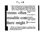
- Fig. 2 is a highly schematic diagram of an embodiment of the system of the invention.
- Fig. 2a is a flow diagram of an embodiment of a method, implemented by the system of Fig. 2 , to modify an image;
- Fig. 2b is an example of an image modified by this method
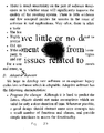
- Fig. 3a is an example of an image as viewed with a blind spot defect in the visual field
- Fig. 3b is an example of an image as viewed with a blind spot defect in the visual field but with the image magnified
- Fig. 3c is an example of an image as viewed with a blind spot defect in the visual field but with magnification and deformation generated by a "pushout" algorithm;
- Fig. 3d is an example of an image as viewed with a blind spot defect in the visual field but with magnification and horizontal spacing generated by a "horizontal split" algorithm;
- Fig. 4 (a-c) respectively depict an image, the image with the gradient applied and the image with the gradient applied with suppression;
- Fig. 5 is a flow diagram of an embodiment of a color-mapping algorithm
- Fig. 6 (a-c) depict respectively an image, and grayscale renderings of the image as a result of mapping colors as would be seen by someone with red-green color blindness.
- the system for augmenting sight in one embodiment includes a pair of eyeglass frames 10 or headmounted display, such as an Nvisor SX, by NVIS (Reston, VA), and a processor 14.
- the processor 14 is a general purpose computer, such as made by Shuttle Computer Group (City of Industry, CA).
- the eyeglass frames 10 are the typical eyeglass frames generally available and used today with transparent lenses. In this embodiment, the transparent lenses have been replaced with one or two display screens 18, 18' (generally 18).
- Attached to the frames 10 are one or more image capture devices 26, such as a camera.
- the image capture device is a Microsoft 2.0M Webcam (Redmond, WA).
- one or more eye or pupil tracking sensors 28 and associated electronics are also attached to the frames 10.
- the electronics provide for image capture by the image capture device 26 and transmission to the processor 14 by way of a wired or wireless link 50.
- the processor 14 includes one or more input output (I/O) modules 34, 34', 34" and a memory 38 in communication with each other by way of a bus as in standard computer design.
- the I/O modules 34, 34', 34" not only receive images from the image capture device 26, but transmit the modified images back to the eyeglass frames 10 for display on one or both of the display screens 18, 18'.
- the resulting images each may be displayed on a respective display 18, 18' to provide depth perception (depending on the capture device position), or one image capture device 18 can select an region of interest (ROI) in the field of view (FOV) of the other image capture device 18' and display the region of interest within the field of view on both displays. In this way, for example, a magnified region of interest may be displayed in the larger field of view.
- ROI region of interest
- FOV field of view
- the displays 18, 18' in the eyeglass frames 10 include, in one embodiment, a thin film display such as a liquid crystal display.
- the displays use Liquid Crystal on Silicon (LCOS) technology.
- the displays use Organic Light Emitting Diode (OLED) technology.
- the displays use micro-projection technology onto a reflective (partial or 100% reflective) glass lens.
- each display shows a different image or the same image. If the modified image is to be displayed only to one eye, only one display 18 is required.
- the displays in various embodiments can incorporate refractive lenses similar to traditional eyeglasses, such that the display works in concert with a person's unique optical prescription.
- the image capture device 26 in one embodiment is a charge coupled device (CCD) camera with high depth-of-field optics.
- the image capture device is a Complimentary Metal Oxide Semiconductor (CMOS) image sensor with appropriate optics.
- the image capture device is any imaging device with an analog or digital signal output that can be sent to a processing unit 14 for processing. In a binocular configuration, each image capture device or camera 26 sees a slightly different image, thereby providing stereoscopic vision to the viewer. If the image is to be presented to only one eye, then only one image capture device or camera 26 is needed to record the image for that eye.
- the image capture device or camera 26 and related electronics are mounted on the eyeglass frames 22, it is contemplated that the camera 26 and electronics could also be located elsewhere on the individual's person. Also, although two cameras 26 are contemplated for binocular vision, it is possible for one camera 26 to view the image and present the same image to both displays 18.
- the source of the image may be another camera, a television, a computer 54 or other source 58 capable of supplying an input to the processor 14.
- the optional eye tracking sensor 28 is also in communication with the electronics and determines where in the visual field the individual is looking. In one embodiment, this sensor 28 operates by following the position of the pupil. Such eye tracking devices 28 are common in presently available "heads-up-displays" utilized by military pilots. Again, although an embodiment contemplated includes two tracking sensors 28, because both eyes typically track together, one tracking device may be used. In another embodiment, the eye tracking sensor 28 uses a combination of mirrors and prisms such that the optical path for the eye tracking sensor 28 is orthogonal to the pupil. Eye tracking is used to determine the region of interest (ROI), and to ensure that the damaged areas of a person's vision are avoided when the modified image is presented to the eye.
- ROI region of interest
- the eye-tracking information is suitably averaged and dampened in software to minimize the sensitivity to random eye movements, blinks, etc., and to optimize the system for various usage models. For example, reading English requires specific eye tracking performance in the left to right direction different from that in the right to left direction, and different again from that in the vertical direction.
- Images from the image capture device 26, eye position information from the eye tracking device 28 and images destined for the displays 18 are passed through the appropriate I/O module 34,34', 34" (HDMI to PCI, VGA, and USB respectively) of the processor 14.
- the display on the NVISOR SX display unit is controlled by an nVIS controller 52 by the same manufacturer of the NVISOR SX display 18.
- This communication between the processor 14 and the electronics of the eyeglass frames 10 may be transmitted through a wired connection 50 or be transmitted wirelessly.
- Certain functions, such as magnification, may be performed in an analog manner, such as by adjusting the lens array on the camera or digitally by mathematically processing pixels.
- the processor 14 is a Shuttle computer having memory 38 and I/O modules 34, 34', and 34".
- the I/O modules 34, 34' and 34" not only communicate with the eyeglass frames 10 but also with other displays and input devices.
- the processor 14 may be connected to a second optional monitor 46, so that a health care provider or device technician can see what the wearer is seeing.
- the NVIS controller 52 is capable of providing video data to a projector 56. In this way, greater numbers of individuals may see what the wearer is seeing.
- display images from a computer 54 or from a video source 58 such as a DVD may be displayed on the display of the eyeglass frames 10. Such images may be used to help train the wearer to diagnose hardware and software failures and to help diagnose and treat the patient.
- an input device such as a DVD player 58 provides a signal to an RF modulator 62 which then passes the RF image signal to the processor 14 through a Win TV NTSC to USB module 66. This signal enters the processor 14 through a USB connector 34".
- image data from a computer monitor 54 may also be displayed on the glasses 10 by converting the signal from the monitor 54 using a VGA to USB converter (for example an Epiphan Systems converter, Ottawa, Ontario, Canada.) 68.
- input commands may be entered by way of a microphone 48 in communication with an iPAQ computer 72.
- the processor 14 in another embodiment is a processing device having cellular telephone capabilities or a software modified cellular telephone.
- data for example from an ophthalmologist or other health care professional 46, may be received from the cellular telephone network and verbal control instructions from the individual 48 may be input through the phone's microphone or alternatively may be keyed in through the phone's touchpad or movement sensor.
- the processor 14 is a specialized computer or handheld device.
- Received data and control instructions are then stored in memory 38.
- the memory 38 includes random access memory (RAM) for data storage and program execution, and read only memory (ROM) for program storage.
- RAM random access memory
- ROM read only memory
- the microprocessor 14 accesses the data in the memory 38 and manipulates it in response to the control instructions for transmission back to the eyeglass frames 10 for display. In this way, the individual can tailor the displayed image for optimal viewing.
- Fig. 2a One embodiment of the method using the system which is capable of modifying an image of the field of view is shown in Fig. 2a .
- the wearer begins by setting the preferred method of determining the location of the region of interest (ROI) through a keyboard or other input device (step 10).
- the individual may indicate his or her preferred location of the ROI by selecting one of a mouse input (step 12), preset coordinates (step 14), or by eye-tracking imaging (step 16).
- an eye-tracking sensor 28 If an eye-tracking sensor 28 is used, the individual only needs to move an eye to determine the region of interest (step 18). Some mathematical parameters are applied to determine the sensitivity of the eye-tracking algorithm in the X and Y directions (step 20) to minimize the effect of involuntary eye movement on the choice of region of interest.
- the center of the region of interest is determined. If the region of interest (ROI) is not within the viewing area (step 22), the region of interest is set to the last valid region of interest (step 24). The complete region of interest (ROI) is then determined, or "mapped" such that it is centered on the coordinates determined (step 26). The size and shape of the ROI is determined through user inputs (step 28).
- the visual information in the region of interest may be input from either the field of view (FOV) image (step 32), or from a separate region of interest image source (step 34), as determined by user input (step 36). If the ROI image is to come from a separate source (step 36), then the user can input an optical zoom requirement (step 38) for this image.
- the ROI image is then captured (step 40) and overlaid or mapped, onto the ROI area (step 42).
- the individual sets the zoom requirement (step 44) for the field of view (FOV) image.
- the zoom function is a combination of both optical zoom done in the FOV camera using lenses, and digital zoom performed by the software.
- the FOV image is then captured. (step 44).
- the image is then modified (steps 24 and 25) as further required by the user input values (steps 46 48, and 54). Note that some modifications are applied to the left and right displays, or left and right eyes, differently (step 52), while others are applied to the left and right displays equally (step 54). Any of the image modifications may be applied to either the region of interest (ROI) or the entire field of view (FOV), or both.
- the final modified images are then presented to the displays (step 58). Fig. 2b depicts what the displayed magnified text would look like.
- the system can also be used to correct vision defects in the eyes of the individual.
- an individual has a defect in his or her visual field that causes a perceived image defect as shown in Fig. 3a .
- an ophthalmologist performs an eye examination on the individual, mapping the areas of the eye which are not functioning properly. This information is downloaded to the memory 38 of the processor 14 through the I/O module 34. The processor 14 can then map the image to avoid the defect as is shown in Figs. 3b , 3c and 3d .
- the end result is that the remapped image removes loss of information (previously hidden behind the defect) caused by the defect as shown in Figs.
- Fig. 3b the text is magnified about the defect region, while in Figs. 3c and 3d the text is remapped to be spaced about the defect.
- the individual may perform many types of image modification by entering data through the keypad of the device or by speaking instructions through the microphone of the device.
- the device is designed to help anyone having to deal with visual challenges which cannot be addressed by simple optical means (glasses, contact lenses, etc). Visual challenges can be due to either less than optimal performance of the visual system or environmental conditions.
- the visual system is a complex structure which combines an optical imaging system (the front end of the eye), a network of sensors (the photoreceptors) positioned at or near the focal plane of the imaging system, and a complex neural network (and its supporting infrastructure of cells) for processing the information from the sensors into a visual signal.
- a problem in either the optical, sensing or neural component of vision will result in less than optimal vision.
- the resulting visual problems can manifest themselves in many ways including, but not limited to, a reduced ability to see fine details; a reduced sensitivity to contrast; a reduced ability to extract color information; a loss in peripheral field of view; a loss of central field of view; and an increased sensitivity to brightness.
- vision loss can be the result of trauma to the eye or disease of the eye. Most of these diseases affect the back of the eye (retina) where light sensing and some signal processing occurs. Glaucoma, diabetic retinopathy, age-related macular degeneration (AMD), and retinitis pigmentosa are some of the more common causes of vision loss in the developed world. The resulting visual problems and their extent vary from almost no noticeable effect to complete blindness and are unique to each patient.
- the invention is not disease specific, and is able to address the major diseases discussed above as well as most other retinal conditions (such as, but not limited to retinopathies, optic disc neuropathies, Stargardt's disease, retinal dystrophies, most variations of macular/foveal edema, etc.) short of profound blindness, by dramatically improving the wearer's visual experience and ability to function beyond that which is possible without the invention.
- retinal conditions such as, but not limited to retinopathies, optic disc neuropathies, Stargardt's disease, retinal dystrophies, most variations of macular/foveal edema, etc.
- the proposed solution can also be helpful, if likely to a lesser extent, to patients with degraded optical properties including optical errors in the cornea (front element of the eye), the crystalline lens (lens inside the eye) and any issues with the liquid contained within the eye (scattering sites, opacification, etc.).
- the invention can also help some people with visual problems due to higher level processing errors in the brain such as, but not limited to, compensating for missing portions of their field of view, problems with tracking, problems that are helped by improving mental focus and removing peripheral distractions (such as dyslexia), etc.
- the device can enhance the amount of information available to normally sighted people. It can overlay multiple sources of information on a same field of view. It can be used in professional applications, for example, to call up stock figures or inform a wearer of incoming email overlaid upon a real-world image while walking down the street; to call up an electrical wiring diagram overlaid with a magnified image of broken down electric circuit to effect a repair. These images will not only be overlaid, but can be manipulated to optimize information delivery and minimize disturbance from natural visual experience. Also, the invention enables hands-free access to this information, which is critically important in some applications.
- the user can issue instructions that cause the processor 14 to perform operations on the image including but not limited to:
- Magnify field of view (FOV) or ROI - this function permits the field of view to be decreased and the resolution increased up to the resolution of the camera and the resolution of the display.
- Minification Reducing the FOV to a smaller size to account for conditions which manifest themselves as "tunnel vision”. This is equivalent to fractional magnification.
- Enhance contrast in entire FOV or only ROI- this function permits contrast contained naturally in the image to be modified so as to enhance the difference between various levels of contrast to improve the detection of information in the image.
- Enhance edges in entire FOV or only in ROI - this function permits the edge of an object in the field of view to be detected and enhanced (for example, but not limited to, adding a black band) to improve the ability of the patient to perceive the edges of different features of the image.
- Threshold grey scale in entire FOV or only in ROI - this function permits all the colors and intensities of the image to be mapped into either black or white.
- Remap image based on the user's blind spot in ROI- this function allows the individual to remap the image to avoid the blind spots caused by diseased regions of the eye, such as in macular degeneration or Stargardt's disease.
- Various algorithms relocate pixels from behind a blind spot to areas near the periphery of the blind spot according to a mathematical spatial distribution model.
- This technique is a specific implementation of "Spatial Remapping" above, where text is moved out from behind a blind spot.
- the technique includes application sensitive techniques such as only splitting the image on the blank lines between text lines, serif removal, text edge smoothing, text enhancement through color and contrast improvement, optical character recognition (OCR), etc.
- Brightness adjustment of field of view or region of interest Individual pixels can be modified to increase or decrease their brightness either globally or according to a mathematically defined spatial distribution.
- Brightness flattening of field of view or region of interest The variation in brightness across an image can be reduced, such that "hotspots" or washed out regions are darkened, and dark areas are brightened.
- Image Superimpositioning This is a technique where peripheral information is overlaid into a central area of the FOV, in order to provide contextual data to people with lost peripheral visual performance.
- Color Identification The invention can identify (via screen text) the dominant color or the statistical red-green-blue (RGB) content for a specific portion of the image, as identified for example by "cross-hairs.”
- RGB red-green-blue
- Black/White Conversion and Inversion of field of view or region of interest Color or grayscale images can be reduced to B/W or inverted B/W (W/B).
- these enhancements may be applied and removed sequentially to an image, that is the image toggled between the actual image or the image as modified, by the user so that the user sees the original image and the enhanced image as a repeating toggled sequence. This provides the user with a clearer sense about what aspects of the presented image are "real" and which are "enhancements".
- an edge enhancement modification can be applied and removed sequentially and repetitively such that the user sees an edge enhanced image and then the unmodified image.
- an edge finding algorithm detects edges using a gradient operator.
- the gradient operator is applied to a low pass digitally filtered version of the image. If the digital filter is a Gaussian, then the gradient of the filtered image is simply the convolution of the image with the gradient of the filter; the Canny Gradient Operator.
- This technique has two major advantages. First, this technique avoids the issue of having to calculate a finite derivative of the natural image. Although the derivative of the Gaussian function is known analytically, the derivative of the natural image is mathematically ill-posed. Second, this technique permits both the filtering and derivative operations to be performed simultaneously in Fourier space. This is represented by:
- f and f ⁇ are the unfiltered and filtered images respectively and g ⁇ is the Gaussian filter.
- the amount of filtering applied will be controlled by the Gaussian width ( ⁇ ).
- ⁇ y ⁇ f ⁇ x ⁇ y f * ⁇ g ⁇ ⁇ y ⁇ x ⁇ y .
- ⁇ ⁇ x ⁇ y atan ⁇ y ⁇ f ⁇ x ⁇ y ⁇ x ⁇ f ⁇ x ⁇ y
- amplitude term which is the vector sum of the two components and a direction component ( ⁇ ).
- ⁇ direction component
- the result of this filtering is a gradient map which does not show edges specifically.
- the gradient image is then processed to identify edges by first using a bi-linear interpolation around each point in the image to identify the points which are local maxima. Once identified, only the local maxima are retained and all other points are ignored. Then the direction of the gradient is used to identify adjacent points which are connected, because the gradient will be similar for adjacent points if they are part of the same edge. Other outliers in the gradient are rejected.
- a thresholding algorithm is applied which retains all gradient points having a value in the upper percentile (in one embodiment, threshold 1, the 90 th ) and rejects all weak gradients having a value in the lower percentile (in one embodiment, threshold 2, the lowest 20 th ). Anything between the two thresholds is rejected if it has no strong companion near it, and kept if its neighborhood indicates an edge. All retained gradient points are then binarised to 1, all others to 0, creating the outline of edges in the image.
- Fig. 4a depicts an image in its natural state.
- Fig. 4b depicts the image of Fig. 4a with a gradient applied
- Fig. 4c depicts the image of Fig. 4b with rejection of pixels below a certain value.
- the algorithm described below is intended to remap the color contained in the field of view to allow the user to extract maximum content information.
- the color content of the processed field of view will not be true to the real world thus actual color information will not always be natural, but the color contrast will be enhanced for the observer so that there will be little or no confusion due to reduced color contrast between the objects in the field of view. This will allow the observer to identify a maximum number of details and maximize information extraction.
- a color perception defect is identified in a patient, then the image is modified by shifting some of the color in the defective color channel (Red-Green or Blue-Yellow) in the other color channel.
- Two parameters are typically required. The first is to identify which colors in the image must be modified, and the second is to determine the amplitude of the color shift necessary to move the affected colors to the unaffected color channel.
- the colors to be modified are selected by the amount of the affected primary color (Red, Green or Blue) in the image. For example, if the color defect is the inability to detect color contrast in the red/green channel, then either the reds or greens are shifted to the blue channel; whichever gives the observer the best contrast. Given that White will contain 33% of each Red, Blue and Green primary color, then the threshold for shifting a given primary color should be >33%. The threshold will be both observer and image dependent and will need to be adjustable. The amount of remapping to the better color channel will also be observer dependent as well as image dependent and thus it too will also need to be adjustable.
- the affected primary color Red, Green or Blue
- a percentage, shf, of the problem primary is shifted into another primary color.
- r(n) (1-shf (r)), where r is the normalized value of the problematic color, and r(n) is the new normalized value for the shifted red primary color.
- b(n) b + shf*r where b(n) is the new normalized value for blue primary.
- g(n) g which means the normalized primary color green (g) is unmodified.
- red is not the problematic color
- similar shifts are possible for the other primary colors.
- the algorithm will shift some of the primary green color (g) into blue.
- the algorithm will shift blue into red.
- An embodiment of the algorithm for automatic brightness and contrast enhancement transforms the image based on the intensity (signal) histogram distribution for the whole image. This technique is usually referred to as brightness/contrast equalization.
- An intensity distribution (number of pixels at each intensity levels), D A from the original image (A) is remapped into a new image (B) with distribution, D B , with the constraints that the remapping result be single valued (each intensity level in D A can only transform to a single intensity level in D B ) and that the transform be reversible or monotonic.
- This embodiment of the algorithm adds additional constraints to the determining the mapping function f(D A ) .
- an additional requirement is that the energy contained within a small region ( dD A ) of the distribution D A must equal the energy to the corresponding region dD B of the distribution D B . That is:
- Fig. 6 shows a grey-scale image of a color blindness test image.
- Figs 6b and 6d depicts grey-scale images of the color blindness test image with the green shift to blue and red shifted to blue, respectively.
- a person with red-green color blindness would be able to easily see portions of the image which would normally appear hidden.
- a patient may use any function which addresses his or her visual defects by entering the requested function using the keypad.
- the parameters which the system used to correct for the defects may need to change over time. This is because typically, over time, the patient's visual preferences may evolve; or the visual defect may worsen due to the aging process, due to an accident, or disease. Further, a patient may simply prefer to change the configuration settings based on the current task they are performing, and as such may have different preferences for different tasks.
- a user using the control features for the display system, can adjust the settings of the optical display, allowing the user to make minor changes to his or her prescription.
- a user When a user requires a minor change to his or her vision system settings, he or she can either go to a vision care professional, who will change the system settings, or change the settings themselves. For example, the user is able to configure a 'recipe' of image modification software algorithms to correct or enhance his or her vision in a simple, time-efficient way for a defined set of visual tasks such as watching TV, reading, playing bridge, needlepoint, etc. without the assistance of a specially trained clinician.
- the user would enter the changes required to their settings to a settings application running on the system.
- the requested changes would then be indicated to the user's clinician or eye doctor by way of the settings application, allowing the new prescription to be downloaded by the optometrist or ophthalmologist.
- the optometrist or ophthalmologist's office system would first be paid for services rendered, by system supplier directly for initially selling the system. All fees for 'Optometric oversight' functions or adjustments would be paid directly by the insurance company or individual patient, to the eye care professional or clinician.
- the system adjustments could also be used to make changes to the user's prescription such that a 'configurable low vision aid' version of the system which incorporates multi-diopter lens characteristics could be used instead of refractive lenses.
Abstract
Description
- This application claims priority to
US provisional application 60/921,468 filed April 2, 2007 - The invention relates generally to the field of vision care and more specifically to the field of augmenting sight.
- There are conditions under which even individuals with 20/20 vision need sight augmentation. Such conditions may be brought on by, for example, low light levels, low or no color differentiation between objects in the visual field, or the small size of the object viewed. Individuals with less than optimal vision or with other visual defects, such as retinopathies, also need augmentation to correct for their visual defects.
-
Fig. 1 is a schematic diagram of the eye. A portion of the retina responsible for fine detail vision is the macula. One form of visual defect is AMD, or age-related macular degeneration. In macular degeneration, which begins with the deposit of druesends in layers beneath the photoreceptors, the degenerative process affects mostly the macula and results in death of cells necessary for vision. In some patents, the result of macular degeneration is a central visual field blind-spot or scotoma. At this time there is no cure for AMD. Other diseases (such as, but not only, diabetic retinopathy, glaucoma, macular edema, and optic nerve atrophy) can also result in significant losses in vision, sometimes macular, sometimes peripheral, to this region of high quality vision. Furthermore, the diseases' impact on vision is unique for each patient. What these vision losses have in common is the loss in quality of life due to the reduced quality of vision. - There have been attempts to augment the quality of the perceived visual field using such items as image intensity amplifiers, or "night scopes", or mechanical or electrical image magnifiers. These devices tend to be big, bulky, limited in their application, and not appropriate for non-military or paramilitary uses.
- What is needed then is a general device that is capable of augmenting an image to be viewed by an individual, whatever the source of the image, be it a computer display, a television or other image source, under the command of that individual, to aid the individual in poor viewing conditions or to overcome physiological and psychological visual defects in the individual. The present invention addresses this need.
- The invention, in one aspect, relates to a method of augmenting sight to be viewed by an individual. In one embodiment, the method comprises the steps of: obtaining an image of a scene viewed by the individual using an image capture device carried by the individual; transmitting the obtained image to a processor carried by the individual; selecting appropriate image modification to be applied to a region of interest in (ROI) in the image by the processor; and operating, by the processor, upon the image to create a modified image in response to the selected image modification or modifications; and displaying the modified image on a display device worn by the individual. In one embodiment, the image modification is magnification. In another embodiment, the image modification is a remapping of the image to avoid visual defects in the individual. In another embodiment, the image modification is minification, or fractional magnification. In another embodiment, the image modification overlays minified peripheral information into the central area of the field of view. In yet another embodiment, the image modification is a remapping of colors within the image. In still yet another embodiment, the image modification is edge enhancement. In another embodiment, the image modification is image intensity enhancement. In one embodiment, the image modification takes place substantially in real time. Other embodiments may include combinations of these and other functions.
- In another aspect, the invention relates to an apparatus for augmenting an image viewed by an individual. In one embodiment, the apparatus comprises an image capture device carried by the individual, for obtaining an image of a scene viewed by the individual; a display carried by the individual; an image modification input device carried by the individual; and a processor carried by the individual. The processor is in communication with the image capture device, image modification input device and display. The processor modifies the image obtained by the image capture device, in response to the instructions provided by the individual using the image modification input device, and displays the modified image on the display carried by the individual.
- In one embodiment, the display comprises a pair of glasses. In another embodiment, the image capture device is attached to a pair of glasses. In yet another embodiment, a second image capture device and a second display are in communication with the processor. The second image capture device provides a second image for the processor to modify and display on either the first or the second display.
- In yet another aspect, the invention relates to a method for improving the visual function. In one embodiment, the method includes the steps of: determining the locations of retinal damage in an eye of the patient; obtaining an image of a scene to be viewed by the patient; and mapping the image to a display in such a way to avoid the locations of retinal damage when the display is viewed by the patient. In another embodiment, the step of obtaining the image uses an image capture device attached to the glasses of the patient. In yet another embodiment, the display replaces a lens of the glasses of the patient.
- Another aspect of the invention relates to an apparatus for improving the visual acuity of a patient with a degenerative disease of the retina. In one embodiment, the apparatus includes a camera for obtaining an image of a scene to be viewed by the patient; a display; a memory storing locations of retinal damage of the eye of the patient; and a processor, in communication with the image capture device, display and memory, for mapping the image to the display in such a way as to avoid the locations of retinal damage when the display is viewed by the patient. In another embodiment, the display replaces a lens of the glasses of the patient.
An aspect of the invention provides a method of augmenting sight in an individual, the method comprising the steps of: obtaining an image of a scene viewed by the individual using a camera carried by the individual; transmitting the obtained image to a processor carried by the individual; selecting an image modification to be applied to the image by the processor; operating, by the processor, upon the image to create a modified image in response to the selected image modification; and displaying the modified image on a display device carried by the individual.
The image modification can be magnification.
The image modification can be a remapping of the image to avoid visual defects in the individual.
The image modification can be a remapping of the colors within the image.
The image modification can be edge enhancement.
The image modification can be at least one of brightness and contrast intensity enhancement.
The image can be modified substantially in real time.
The modification to the image can be alternatively applied and removed.
An aspect of the invention provides an apparatus for augmenting sight in an individual comprising: a camera, carried by the individual, for obtaining an image of a scene viewed by the individual; a display carried by the individual; an image modification input device carried by the individual; and a processor, carried by the individual, the processor in communication with the camera, image modification input device and display, the processor for modifying the image obtained by the camera, in response to the instructions provided by the individual using the image modification input device, and for displaying the modified image on the display carried by the individual.
The display can comprise a pair of eyeglass frames.
The camera can be attached to the pair of eyeglass frames.
The apparatus can further comprise a second camera and a second display in communication with the processor, the second camera providing a second image for the processor to modify and display.
An aspect of the invention provides a method for improving the visual acuity of a patient with retinal defects comprising the steps of: determining the locations of retinal damage in an eye of the patient; obtaining an image of a scene viewed by the patient; and mapping the image to a display in such a way to avoid the locations of retinal damage when the display is viewed by the patient.
The step of obtaining the image can use a camera attached to eyeglass frames worn by the patient.
The display can replace a lens of the eyeglass frames worn by the patient.
The locations of retinal damage can be determined by a health professional.
The method can further comprise the step of modifying the image according to instructions issued by the patient.
The instructions can be verbal.
The instructions can be selected from a set of instructions comprising magnify, edge enhance, remap color, remap visual field, contrast enhance and brightness enhance the image.
An aspect of the invention provides apparatus for improving the visual acuity of a patient with retinal damage, the apparatus comprising: a camera, carried by the patient, for obtaining an image of a scene viewed by the patient; a display, carried by the patient; a memory for storing locations of retinal damage in an eye of the patient; and a processor, in communication with the camera, display and memory, for mapping the obtained image to the display in such a way to avoid the locations of retinal damage when the display is viewed by the patient.
The camera can be a video source selected from the group comprising a camera, a television, and a computer.
An aspect of the invention provides an apparatus for augmenting sight in an individual comprising: an image capture device, carried by the individual, for obtaining an image of a scene viewed by the individual; a display carried by the individual; an image modification input device carried by the individual; and a pupil tracking device mounted to observe the directional of movement of a users pupil; and a processor, carried by the individual, the processor in communication with the image capture device, image modification input device and display, the processor for modifying the image obtained by the image capture device, in response to the instructions provided by the individual using the image modification input device, and for displaying the modified image on the display carried by the individual.
An aspect of the invention provides a method for providing remuneration to a clinician utilizing a user-selected image enhancement system comprising a camera, a personal display, an image modification input device, and a processor, wherein the processor modifies the image obtained by the camera, in response to the instructions provided by the user using the image modification input device, and displays the modified image on the display, the method comprising the steps of: one or more of synthesizing, reviewing, modifying or approving the user-selected image enhancement; and upon the approval of the user-selected image enhancement, compensating the clinician.
The clinician can be remote from the system and the compensation can occur through electronic funds transfer. - The invention is pointed out with particularity in the appended claims. The advantages of the invention described above, together with further advantages, may be better understood by referring to the following description taken in conjunction with the accompanying drawings. In the drawings, like reference characters generally refer to the same parts throughout the different views. The drawings are not necessarily to scale, emphasis instead generally being placed upon illustrating the principles of the invention.
-
Fig. 1 is a diagram of the eye; -
Fig. 2 is a highly schematic diagram of an embodiment of the system of the invention; -
Fig. 2a is a flow diagram of an embodiment of a method, implemented by the system ofFig. 2 , to modify an image; -
Fig. 2b is an example of an image modified by this method; [0017]Fig. 3a is an example of an image as viewed with a blind spot defect in the visual field; -
Fig. 3b is an example of an image as viewed with a blind spot defect in the visual field but with the image magnified -
Fig. 3c is an example of an image as viewed with a blind spot defect in the visual field but with magnification and deformation generated by a "pushout" algorithm; -
Fig. 3d is an example of an image as viewed with a blind spot defect in the visual field but with magnification and horizontal spacing generated by a "horizontal split" algorithm; -
Fig. 4 (a-c) respectively depict an image, the image with the gradient applied and the image with the gradient applied with suppression; -
Fig. 5 is a flow diagram of an embodiment of a color-mapping algorithm; -
Fig. 6 (a-c) depict respectively an image, and grayscale renderings of the image as a result of mapping colors as would be seen by someone with red-green color blindness. - In brief overview and referring to
Fig. 2 , the system for augmenting sight in one embodiment includes a pair of eyeglass frames 10 or headmounted display, such as an Nvisor SX, by NVIS (Reston, VA), and aprocessor 14. In one embodiment, theprocessor 14 is a general purpose computer, such as made by Shuttle Computer Group (City of Industry, CA). The eyeglass frames 10 are the typical eyeglass frames generally available and used today with transparent lenses. In this embodiment, the transparent lenses have been replaced with one or twodisplay screens 18, 18' (generally 18). Attached to theframes 10 are one or moreimage capture devices 26, such as a camera. In one embodiment, the image capture device is a Microsoft 2.0M Webcam (Redmond, WA). Optionally, one or more eye orpupil tracking sensors 28 and associated electronics are also attached to theframes 10. The electronics provide for image capture by theimage capture device 26 and transmission to theprocessor 14 by way of a wired orwireless link 50. Theprocessor 14 includes one or more input output (I/O)modules memory 38 in communication with each other by way of a bus as in standard computer design. The I/O modules image capture device 26, but transmit the modified images back to the eyeglass frames 10 for display on one or both of the display screens 18, 18'. With two or moreimage capture devices 26, the resulting images each may be displayed on arespective display 18, 18' to provide depth perception (depending on the capture device position), or oneimage capture device 18 can select an region of interest (ROI) in the field of view (FOV) of the other image capture device 18' and display the region of interest within the field of view on both displays. In this way, for example, a magnified region of interest may be displayed in the larger field of view. - In more detail, in various embodiments, the
displays 18, 18' in the eyeglass frames 10 include, in one embodiment, a thin film display such as a liquid crystal display. In another embodiment, the displays use Liquid Crystal on Silicon (LCOS) technology. In a further embodiment, the displays use Organic Light Emitting Diode (OLED) technology. In still a further embodiment, the displays use micro-projection technology onto a reflective (partial or 100% reflective) glass lens. In various embodiments, each display shows a different image or the same image. If the modified image is to be displayed only to one eye, only onedisplay 18 is required. The displays in various embodiments can incorporate refractive lenses similar to traditional eyeglasses, such that the display works in concert with a person's unique optical prescription. - Similarly, the
image capture device 26 in one embodiment is a charge coupled device (CCD) camera with high depth-of-field optics. In another embodiment, the image capture device is a Complimentary Metal Oxide Semiconductor (CMOS) image sensor with appropriate optics. In other various embodiments, the image capture device is any imaging device with an analog or digital signal output that can be sent to aprocessing unit 14 for processing. In a binocular configuration, each image capture device orcamera 26 sees a slightly different image, thereby providing stereoscopic vision to the viewer. If the image is to be presented to only one eye, then only one image capture device orcamera 26 is needed to record the image for that eye. Although, in the embodiment shown, the image capture device orcamera 26 and related electronics are mounted on the eyeglass frames 22, it is contemplated that thecamera 26 and electronics could also be located elsewhere on the individual's person. Also, although twocameras 26 are contemplated for binocular vision, it is possible for onecamera 26 to view the image and present the same image to bothdisplays 18. In addition, in various other embodiments the source of the image may be another camera, a television, acomputer 54 orother source 58 capable of supplying an input to theprocessor 14. - The optional
eye tracking sensor 28 is also in communication with the electronics and determines where in the visual field the individual is looking. In one embodiment, thissensor 28 operates by following the position of the pupil. Sucheye tracking devices 28 are common in presently available "heads-up-displays" utilized by military pilots. Again, although an embodiment contemplated includes two trackingsensors 28, because both eyes typically track together, one tracking device may be used. In another embodiment, theeye tracking sensor 28 uses a combination of mirrors and prisms such that the optical path for theeye tracking sensor 28 is orthogonal to the pupil. Eye tracking is used to determine the region of interest (ROI), and to ensure that the damaged areas of a person's vision are avoided when the modified image is presented to the eye. The eye-tracking information is suitably averaged and dampened in software to minimize the sensitivity to random eye movements, blinks, etc., and to optimize the system for various usage models. For example, reading English requires specific eye tracking performance in the left to right direction different from that in the right to left direction, and different again from that in the vertical direction. - Images from the
image capture device 26, eye position information from theeye tracking device 28 and images destined for thedisplays 18 are passed through the appropriate I/O module processor 14. In the embodiment shown, the display on the NVISOR SX display unit is controlled by annVIS controller 52 by the same manufacturer of theNVISOR SX display 18. This communication between theprocessor 14 and the electronics of the eyeglass frames 10 may be transmitted through awired connection 50 or be transmitted wirelessly. Certain functions, such as magnification, may be performed in an analog manner, such as by adjusting the lens array on the camera or digitally by mathematically processing pixels. - In the embodiment shown, the
processor 14 is a Shuttlecomputer having memory 38 and I/O modules O modules processor 14 may be connected to a secondoptional monitor 46, so that a health care provider or device technician can see what the wearer is seeing. In addition, theNVIS controller 52 is capable of providing video data to aprojector 56. In this way, greater numbers of individuals may see what the wearer is seeing. - Additionally, display images from a
computer 54 or from avideo source 58 such as a DVD may be displayed on the display of the eyeglass frames 10. Such images may be used to help train the wearer to diagnose hardware and software failures and to help diagnose and treat the patient. In one embodiment, an input device such as aDVD player 58 provides a signal to anRF modulator 62 which then passes the RF image signal to theprocessor 14 through a Win TV NTSC toUSB module 66. This signal enters theprocessor 14 through aUSB connector 34". Similarly, image data from acomputer monitor 54 may also be displayed on theglasses 10 by converting the signal from themonitor 54 using a VGA to USB converter (for example an Epiphan Systems converter, Ottawa, Ontario, Canada.) 68. Additionally, the user may wear a ring-like "text-camera" on his or her finger which he or she then scans over a line of text. Such devices reduce the optical complexity of theeyeglass camera 26. Finally, in this embodiment, input commands may be entered by way of amicrophone 48 in communication with aniPAQ computer 72. - The
processor 14 in another embodiment is a processing device having cellular telephone capabilities or a software modified cellular telephone. In this embodiment data, for example from an ophthalmologist or other health care professional 46, may be received from the cellular telephone network and verbal control instructions from the individual 48 may be input through the phone's microphone or alternatively may be keyed in through the phone's touchpad or movement sensor. In other embodiments, theprocessor 14 is a specialized computer or handheld device. - Received data and control instructions are then stored in
memory 38. Thememory 38 includes random access memory (RAM) for data storage and program execution, and read only memory (ROM) for program storage. Themicroprocessor 14 accesses the data in thememory 38 and manipulates it in response to the control instructions for transmission back to the eyeglass frames 10 for display. In this way, the individual can tailor the displayed image for optimal viewing. - One embodiment of the method using the system which is capable of modifying an image of the field of view is shown in
Fig. 2a . The wearer begins by setting the preferred method of determining the location of the region of interest (ROI) through a keyboard or other input device (step 10). The individual may indicate his or her preferred location of the ROI by selecting one of a mouse input (step 12), preset coordinates (step 14), or by eye-tracking imaging (step 16). - If an eye-tracking
sensor 28 is used, the individual only needs to move an eye to determine the region of interest (step 18). Some mathematical parameters are applied to determine the sensitivity of the eye-tracking algorithm in the X and Y directions (step 20) to minimize the effect of involuntary eye movement on the choice of region of interest. - From this information, the center of the region of interest (ROI) is determined. If the region of interest (ROI) is not within the viewing area (step 22), the region of interest is set to the last valid region of interest (step 24). The complete region of interest (ROI) is then determined, or "mapped" such that it is centered on the coordinates determined (step 26). The size and shape of the ROI is determined through user inputs (step 28).
- The visual information in the region of interest (ROI) may be input from either the field of view (FOV) image (step 32), or from a separate region of interest image source (step 34), as determined by user input (step 36). If the ROI image is to come from a separate source (step 36), then the user can input an optical zoom requirement (step 38) for this image. The ROI image is then captured (step 40) and overlaid or mapped, onto the ROI area (step 42).
- The individual sets the zoom requirement (step 44) for the field of view (FOV) image. The zoom function is a combination of both optical zoom done in the FOV camera using lenses, and digital zoom performed by the software. The FOV image is then captured. (step 44).
- The image is then modified (
steps 24 and 25) as further required by the user input values (steps 46 48, and 54). Note that some modifications are applied to the left and right displays, or left and right eyes, differently (step 52), while others are applied to the left and right displays equally (step 54). Any of the image modifications may be applied to either the region of interest (ROI) or the entire field of view (FOV), or both. The final modified images are then presented to the displays (step 58).Fig. 2b depicts what the displayed magnified text would look like. - Referring also to
Figs. 3 , the system can also be used to correct vision defects in the eyes of the individual. In this example, an individual has a defect in his or her visual field that causes a perceived image defect as shown inFig. 3a . As a first step, an ophthalmologist performs an eye examination on the individual, mapping the areas of the eye which are not functioning properly. This information is downloaded to thememory 38 of theprocessor 14 through the I/O module 34. Theprocessor 14 can then map the image to avoid the defect as is shown inFigs. 3b ,3c and3d . The end result is that the remapped image removes loss of information (previously hidden behind the defect) caused by the defect as shown inFigs. 3b ,3c , and3d . InFig. 3b the text is magnified about the defect region, while inFigs. 3c and3d the text is remapped to be spaced about the defect. Thus, with training the individual is capable of seeing a full image substantially free of distortion. The individual may perform many types of image modification by entering data through the keypad of the device or by speaking instructions through the microphone of the device. - The device is designed to help anyone having to deal with visual challenges which cannot be addressed by simple optical means (glasses, contact lenses, etc). Visual challenges can be due to either less than optimal performance of the visual system or environmental conditions. The visual system is a complex structure which combines an optical imaging system (the front end of the eye), a network of sensors (the photoreceptors) positioned at or near the focal plane of the imaging system, and a complex neural network (and its supporting infrastructure of cells) for processing the information from the sensors into a visual signal. A problem in either the optical, sensing or neural component of vision will result in less than optimal vision. The resulting visual problems can manifest themselves in many ways including, but not limited to, a reduced ability to see fine details; a reduced sensitivity to contrast; a reduced ability to extract color information; a loss in peripheral field of view; a loss of central field of view; and an increased sensitivity to brightness.
- These various types of vision loss can be the result of trauma to the eye or disease of the eye. Most of these diseases affect the back of the eye (retina) where light sensing and some signal processing occurs. Glaucoma, diabetic retinopathy, age-related macular degeneration (AMD), and retinitis pigmentosa are some of the more common causes of vision loss in the developed world. The resulting visual problems and their extent vary from almost no noticeable effect to complete blindness and are unique to each patient.
- The invention is not disease specific, and is able to address the major diseases discussed above as well as most other retinal conditions (such as, but not limited to retinopathies, optic disc neuropathies, Stargardt's disease, retinal dystrophies, most variations of macular/foveal edema, etc.) short of profound blindness, by dramatically improving the wearer's visual experience and ability to function beyond that which is possible without the invention.
- The proposed solution can also be helpful, if likely to a lesser extent, to patients with degraded optical properties including optical errors in the cornea (front element of the eye), the crystalline lens (lens inside the eye) and any issues with the liquid contained within the eye (scattering sites, opacification, etc.).
- Finally, the invention can also help some people with visual problems due to higher level processing errors in the brain such as, but not limited to, compensating for missing portions of their field of view, problems with tracking, problems that are helped by improving mental focus and removing peripheral distractions (such as dyslexia), etc.
- Outside of visual problems, there are many environmental conditions that can lead to poor visual information transfer, such as, trying to look at someone's face while they stand in front of a window on a bright sunny day, looking at a baseball game where part of the field is in sunlight and another in shadows, poor quality illumination (lots of blue for example). The device can certainly help most of these people reduce the impact of the environmental condition on their visual performance. These conditions can occur during work or leisure activities, for example, facing the sun up on a telephone pole while performing a repair, walking the dog, attending a sports event, etc.
- Finally, the device can enhance the amount of information available to normally sighted people. It can overlay multiple sources of information on a same field of view. It can be used in professional applications, for example, to call up stock figures or inform a wearer of incoming email overlaid upon a real-world image while walking down the street; to call up an electrical wiring diagram overlaid with a magnified image of broken down electric circuit to effect a repair. These images will not only be overlaid, but can be manipulated to optimize information delivery and minimize disturbance from natural visual experience. Also, the invention enables hands-free access to this information, which is critically important in some applications.
- To correct for these conditions, the user can issue instructions that cause the
processor 14 to perform operations on the image including but not limited to: - 1. Magnify field of view (FOV) or ROI - this function permits the field of view to be decreased and the resolution increased up to the resolution of the camera and the resolution of the display.
- 2. Minification: Reducing the FOV to a smaller size to account for conditions which manifest themselves as "tunnel vision". This is equivalent to fractional magnification.
- 3. Enhance contrast in entire FOV or only ROI- this function permits contrast contained naturally in the image to be modified so as to enhance the difference between various levels of contrast to improve the detection of information in the image.
- 4. Enhance edges in entire FOV or only in ROI - this function permits the edge of an object in the field of view to be detected and enhanced (for example, but not limited to, adding a black band) to improve the ability of the patient to perceive the edges of different features of the image.
- 5. Change to grey scale in entire FOV or only in ROI - this function permits the image to be converted to a grey scale from a color scale.
- 6. Threshold grey scale in entire FOV or only in ROI - this function permits all the colors and intensities of the image to be mapped into either black or white.
- 7. Remap colors in entire FOV or only in ROI- this function remaps the colors in the original image into another range of colors, thereby permitting color blindness or deficiency to be ameliorated.
- 8. Remap image based on the user's blind spot in ROI- this function allows the individual to remap the image to avoid the blind spots caused by diseased regions of the eye, such as in macular degeneration or Stargardt's disease. Various algorithms relocate pixels from behind a blind spot to areas near the periphery of the blind spot according to a mathematical spatial distribution model.
- 9. Relocation and Enhancement of Text: This technique is a specific implementation of "Spatial Remapping" above, where text is moved out from behind a blind spot. The technique includes application sensitive techniques such as only splitting the image on the blank lines between text lines, serif removal, text edge smoothing, text enhancement through color and contrast improvement, optical character recognition (OCR), etc.
- 10. Brightness adjustment of field of view or region of interest: Individual pixels can be modified to increase or decrease their brightness either globally or according to a mathematically defined spatial distribution.
- 11. Brightness flattening of field of view or region of interest: The variation in brightness across an image can be reduced, such that "hotspots" or washed out regions are darkened, and dark areas are brightened.
- 12. Image Superimpositioning: This is a technique where peripheral information is overlaid into a central area of the FOV, in order to provide contextual data to people with lost peripheral visual performance.
- 14. Color Identification: The invention can identify (via screen text) the dominant color or the statistical red-green-blue (RGB) content for a specific portion of the image, as identified for example by "cross-hairs."
- 15. Black/White Conversion and Inversion of field of view or region of interest: Color or grayscale images can be reduced to B/W or inverted B/W (W/B).
- By using fast processors it is possible to make these modifications in substantially real time. This allows a visually impaired individual to function substantially as if there were no visual defect. With a fast enough computer, these enhancements may be applied and removed sequentially to an image, that is the image toggled between the actual image or the image as modified, by the user so that the user sees the original image and the enhanced image as a repeating toggled sequence. This provides the user with a clearer sense about what aspects of the presented image are "real" and which are "enhancements".
- Further certain enhancements can be applied and removed from the image automatically. For example, an edge enhancement modification can be applied and removed sequentially and repetitively such that the user sees an edge enhanced image and then the unmodified image.
- Many algorithms can be used to achieve these purposes. For example, one embodiment of an edge finding algorithm detects edges using a gradient operator. To avoid noise due to small natural variations in intensity of the image, the gradient operator is applied to a low pass digitally filtered version of the image. If the digital filter is a Gaussian, then the gradient of the filtered image is simply the convolution of the image with the gradient of the filter; the Canny Gradient Operator. This technique has two major advantages. First, this technique avoids the issue of having to calculate a finite derivative of the natural image. Although the derivative of the Gaussian function is known analytically, the derivative of the natural image is mathematically ill-posed. Second, this technique permits both the filtering and derivative operations to be performed simultaneously in Fourier space. This is represented by:
-

- where f and f σ are the unfiltered and filtered images respectively and g σ is the Gaussian filter. The amount of filtering applied will be controlled by the Gaussian width (σ). One embodiment of the implementation separates the gradient operator into its two Cartesian coordinates, so that in its final form the gradient is:

-

- This generates an amplitude term (M) which is the vector sum of the two components and a direction component (θ). The result of this filtering is a gradient map which does not show edges specifically. The gradient image is then processed to identify edges by first using a bi-linear interpolation around each point in the image to identify the points which are local maxima. Once identified, only the local maxima are retained and all other points are ignored. Then the direction of the gradient is used to identify adjacent points which are connected, because the gradient will be similar for adjacent points if they are part of the same edge. Other outliers in the gradient are rejected. Finally, a thresholding algorithm is applied which retains all gradient points having a value in the upper percentile (in one embodiment,
threshold 1, the 90th) and rejects all weak gradients having a value in the lower percentile (in one embodiment,threshold 2, the lowest 20th). Anything between the two thresholds is rejected if it has no strong companion near it, and kept if its neighborhood indicates an edge. All retained gradient points are then binarised to 1, all others to 0, creating the outline of edges in the image.Fig. 4a depicts an image in its natural state.Fig. 4b depicts the image ofFig. 4a with a gradient applied, andFig. 4c depicts the image ofFig. 4b with rejection of pixels below a certain value. - Similarly, an example of a color remapping algorithm is next described. Normally sighted people depend on both brightness and color differences (luminance and color contrast) to identify features in their visual field. Abnormal color vision will often result in the inability to distinguish between colors; a reduced capacity to use color contrast to extract information. Color confusion is usually asymmetric, so that color confusion occurs along the Red-Green or Yellow-Blue color axis. This means that by remapping colors in the field of view which are confusing to an observer to colors in the spectrum which offer better contrast, it is possible for the user to recover the information content of the field of view.
- The algorithm described below is intended to remap the color contained in the field of view to allow the user to extract maximum content information. The color content of the processed field of view will not be true to the real world thus actual color information will not always be natural, but the color contrast will be enhanced for the observer so that there will be little or no confusion due to reduced color contrast between the objects in the field of view. This will allow the observer to identify a maximum number of details and maximize information extraction.
- The algorithm is illustrated in
Fig 5 . If a color perception defect is identified in a patient, then the image is modified by shifting some of the color in the defective color channel (Red-Green or Blue-Yellow) in the other color channel. Two parameters are typically required. The first is to identify which colors in the image must be modified, and the second is to determine the amplitude of the color shift necessary to move the affected colors to the unaffected color channel. - First, the colors to be modified are selected by the amount of the affected primary color (Red, Green or Blue) in the image. For example, if the color defect is the inability to detect color contrast in the red/green channel, then either the reds or greens are shifted to the blue channel; whichever gives the observer the best contrast. Given that White will contain 33% of each Red, Blue and Green primary color, then the threshold for shifting a given primary color should be >33%. The threshold will be both observer and image dependent and will need to be adjustable. The amount of remapping to the better color channel will also be observer dependent as well as image dependent and thus it too will also need to be adjustable.
- For each point in the image, where R, G and B represents the intensity of each primary color, the algorithm proceeds as follows:
- First, the RGB values are measured, and the brightness (T) (T= R+G+B) and the normalized color values (r,g,b) (r=R/T, g=G/T and b=B/T) calculated. Next, for each point in the image where the color contains more than the threshold amount of the problematic primary color, a percentage, shf, of the problem primary is shifted into another primary color.
- For example, if (r) is the normalized value of the problematic color then:
- If r>0.4 then red the primary color is more than 40% of the color of the image and hence above the threshold.
- r(n)= (1-shf (r)), where r is the normalized value of the problematic color, and r(n) is the new normalized value for the shifted red primary color. Similarly, b(n)= b + shf*r where b(n) is the new normalized value for blue primary. Finally, g(n) = g which means the normalized primary color green (g) is unmodified.
- One skilled in the art would recognize that if red is not the problematic color, then similar shifts are possible for the other primary colors. Thus, if the problem primary color is green (g) then the algorithm will shift some of the primary green color (g) into blue. Similarly, if the primary color blue is the problem, then the algorithm will shift blue into red.
- The new RGB coordinates of the point being examined is then the new normalized shifted color times the brightness T. Thus Rn= m*T, Gn=gn*T and Bn=bn*T. The results of this algorithm are shown in
Figs. 6a-c . - An embodiment of the algorithm for automatic brightness and contrast enhancement transforms the image based on the intensity (signal) histogram distribution for the whole image. This technique is usually referred to as brightness/contrast equalization. An intensity distribution (number of pixels at each intensity levels), DA , from the original image (A) is remapped into a new image (B) with distribution, DB, with the constraints that the remapping result be single valued (each intensity level in DA can only transform to a single intensity level in DB ) and that the transform be reversible or monotonic.
- These constraints are embodied in the equations:
-

- and
-

- Many different transforms can be used that meet these constraints. One embodiment is the algorithm discussed below. This algorithm is a simple and effective approach that is widely used in the image processing world.
- This embodiment of the algorithm adds additional constraints to the determining the mapping function f(DA). In one embodiment, an additional requirement is that the energy contained within a small region (dDA ) of the distribution DA must equal the energy to the corresponding region dDB of the distribution DB. That is:
-

- where h is the number of pixels at a predetermined intensity level, (x). If the values of h are rescaled by dividing the value by the total number of pixels then the values of h can be expressed as probability distributions pA and pB. Furthermore, because the intensity distribution is being stretched from the original image (0 to a maximum intensity, DM ) and because the area under the two probability distributions must be equal as described above, then the derivative of the transfer function df =df(x)/dx, can be set to a constant equal to DM. The transform function is then rewritten in terms of the probability distribution pA and DM :
-

- where FA(DA) is the cumulative distribution function for the original image. The implementation then becomes:
- First, obtain an intensity distribution function for the original image with the same number of bins available as there are available grey levels for the display mode (that is, 8 bits gives you 256 potential bins.)
- Next, normalize the distribution function by dividing it by the number of pixels to convert the distribution function to a probability function.
- Third, find the largest gray level with a non zero value in the original image and set this to DM.
- Fourth, create a cumulative distribution function: For example bin 0 is the number of pixels of brightness = 0;
bin 1 is sum of the number of pixels inbin 0 and 1;bin 2 is sum of pixels inbins - Fifth, for each pixel, obtain the intensity, I(c,r) where c and r are the column and row indices, and find the cumulative probability for that intensity I(c,r); a value between 0 and 1.
- Then multiply this value by DM. This is the new value of the intensity for that pixel, after equalization.
- Finally, to obtain stretching as well, multiply the new intensity value by the ratio of the maximum possible for display divided by DM. This step ensures the maximum contrast.
Fig. 6 shows a grey-scale image of a color blindness test image.Figs 6b and 6d depicts grey-scale images of the color blindness test image with the green shift to blue and red shifted to blue, respectively. Thus a person with red-green color blindness would be able to easily see portions of the image which would normally appear hidden. - A patient may use any function which addresses his or her visual defects by entering the requested function using the keypad. However, the parameters which the system used to correct for the defects may need to change over time. This is because typically, over time, the patient's visual preferences may evolve; or the visual defect may worsen due to the aging process, due to an accident, or disease. Further, a patient may simply prefer to change the configuration settings based on the current task they are performing, and as such may have different preferences for different tasks. Thus a user, using the control features for the display system, can adjust the settings of the optical display, allowing the user to make minor changes to his or her prescription.
- When a user requires a minor change to his or her vision system settings, he or she can either go to a vision care professional, who will change the system settings, or change the settings themselves. For example, the user is able to configure a 'recipe' of image modification software algorithms to correct or enhance his or her vision in a simple, time-efficient way for a defined set of visual tasks such as watching TV, reading, playing bridge, needlepoint, etc. without the assistance of a specially trained clinician.
- For major changes to the system settings, professional ophthalmic oversight may still be required. For example, the ability for a clinician to synthesize, review, modify and, if deemed appropriate, approve a user-selected image enhancement 'recipe' as above, may be required for regulated activities such as driving. The software 'recipe' would not become operational in the system, which is identified by a unique software serial number, unless and until activated by the clinician. Typically, the clinician is also identified by a unique secure government identification number provided to those clinicians authorized to approve visual aids for driving. The clinician may interact with the system directly or may remotely connect to the system. Upon clinician approval of the prescription, the clinician would then receive compensation for services. The compensation is provided by way of funds transfer from one or both of the system manufacturer, distributors or dealers and the user or his or her insurance company. The funds transfer in one embodiment is done electronically.
- For example, in one embodiment, the user would enter the changes required to their settings to a settings application running on the system. The requested changes would then be indicated to the user's clinician or eye doctor by way of the settings application, allowing the new prescription to be downloaded by the optometrist or ophthalmologist. The optometrist or ophthalmologist's office system would first be paid for services rendered, by system supplier directly for initially selling the system. All fees for 'Optometric oversight' functions or adjustments would be paid directly by the insurance company or individual patient, to the eye care professional or clinician. The system adjustments could also be used to make changes to the user's prescription such that a 'configurable low vision aid' version of the system which incorporates multi-diopter lens characteristics could be used instead of refractive lenses.
- While the present invention has been described in terms of certain exemplary preferred embodiments, it will be readily understood and appreciated by one of ordinary skill in the art that it is not so limited, and that many additions, deletions and modifications to the preferred embodiments may be made within the scope of the invention as hereinafter claimed. Accordingly, the scope of the invention is limited only by the scope of the appended claims.
Claims (15)
- A method for improving the visual acuity of a patient with retinal defects comprising the steps of:determining the locations of retinal damage in an eye of the patient;obtaining an image of a scene viewed by the patient; andmapping the image to a display in such a way to avoid the locations of retinal damage when the display is viewed by the patient.
- The method of claim 1 wherein mapping the image to a display comprises generating with a processor in dependence upon at least the image and data relating to locations of retinal damage a modified image in such a way to avoid the locations of retinal damage of the individual when the modified image is viewed by the individual upon the display.
- The method of claim 2 wherein the modified image includes at least one of magnification, reduction, edge enhancement, remapping colour, remapping the visual field, colour balance, text enhancement, contrast adjustment and brightness adjustment.
- The method of claim 2 wherein the modified image is generated in dependence upon instructions provided to the processor by the patient.
- The method of claim 4 wherein the instructions relate to at least one of magnification, reduction, edge enhancement, remapping colour, remapping the visual field, colour balance, text enhancement, contrast adjustment and brightness adjustment.
- The method of claim 1 wherein the image is obtained from a video source comprising at least one of a camera, a television, a computer, the Internet, a multimedia data file, and a camera attached to an eyeglass frame worn by the patient..
- The method of claim 2 wherein the modified image is generated substantially in real time.
- The method of claim 2 wherein modification of the image is alternatively applied and removed when displayed to the patient.
- An apparatus for augmenting sight in a patient comprising:a camera, carried by the patient, for obtaining an image of a scene viewed by the patient;a display carried by the patient;a memory for storing locations of retinal damage in an eye of the patient; anda processor, carried by the patient, the processor in communication with the camera, memory, and display, the processor for modifying the image obtained by the camera, in response to the stored locations of retinal damage in an eye of the patient, and for displaying the modified image on the display carried by the patient.
- The apparatus of claim 9 wherein modifying the image includes at least one of magnification, reduction, edge enhancement, remapping colour, remapping the visual field, colour balance, text enhancement, contrast adjustment and brightness adjustment.
- The apparatus of claim 9 wherein the modified image is generated in dependence upon instructions provided to the processor by the patient.
- The apparatus of claim 11 wherein the instructions relate to at least one of magnification, reduction, edge enhancement, remapping colour, remapping the visual field, colour balance, text enhancement, contrast adjustment and brightness adjustment.
- The apparatus of claim 9 wherein modifying the image obtained by the camera in response to the stored locations of retinal damage in an eye of the patient comprises generating with the processor in dependence upon at least the image and data relating to locations of retinal damage a modified image in such a way to avoid the locations of retinal damage of the individual when the modified image is viewed by the patient upon the display.
- The apparatus of claim 9 wherein the image is modified substantially in real time.
- The apparatus of claim 9 wherein the modification to the image is alternatively applied and removed when displayed to the patient.
Priority Applications (1)
| Application Number | Priority Date | Filing Date | Title |
|---|---|---|---|
| EP18211645.9A EP3515063A1 (en) | 2007-04-02 | 2008-04-02 | A method for augmenting sight |
Applications Claiming Priority (3)
| Application Number | Priority Date | Filing Date | Title |
|---|---|---|---|
| US92146807P | 2007-04-02 | 2007-04-02 | |
| PCT/CA2008/000635 WO2008119187A1 (en) | 2007-04-02 | 2008-04-02 | An apparatus and method for augmenting sight |
| EP08733716A EP2143273A4 (en) | 2007-04-02 | 2008-04-02 | An apparatus and method for augmenting sight |
Related Parent Applications (2)
| Application Number | Title | Priority Date | Filing Date |
|---|---|---|---|
| EP08733716.8 Division | 2008-04-02 | ||
| EP08733716A Division EP2143273A4 (en) | 2007-04-02 | 2008-04-02 | An apparatus and method for augmenting sight |
Related Child Applications (2)
| Application Number | Title | Priority Date | Filing Date |
|---|---|---|---|
| EP18211645.9A Division EP3515063A1 (en) | 2007-04-02 | 2008-04-02 | A method for augmenting sight |
| EP18211645.9A Division-Into EP3515063A1 (en) | 2007-04-02 | 2008-04-02 | A method for augmenting sight |
Publications (2)
| Publication Number | Publication Date |
|---|---|
| EP2621169A1 true EP2621169A1 (en) | 2013-07-31 |
| EP2621169B1 EP2621169B1 (en) | 2023-07-19 |
Family
ID=39807769
Family Applications (3)
| Application Number | Title | Priority Date | Filing Date |
|---|---|---|---|
| EP18211645.9A Withdrawn EP3515063A1 (en) | 2007-04-02 | 2008-04-02 | A method for augmenting sight |
| EP08733716A Withdrawn EP2143273A4 (en) | 2007-04-02 | 2008-04-02 | An apparatus and method for augmenting sight |
| EP13154099.9A Active EP2621169B1 (en) | 2007-04-02 | 2008-04-02 | An apparatus and method for augmenting sight |
Family Applications Before (2)
| Application Number | Title | Priority Date | Filing Date |
|---|---|---|---|
| EP18211645.9A Withdrawn EP3515063A1 (en) | 2007-04-02 | 2008-04-02 | A method for augmenting sight |
| EP08733716A Withdrawn EP2143273A4 (en) | 2007-04-02 | 2008-04-02 | An apparatus and method for augmenting sight |
Country Status (4)
| Country | Link |
|---|---|
| US (5) | US8135227B2 (en) |
| EP (3) | EP3515063A1 (en) |
| CA (2) | CA2682624C (en) |
| WO (1) | WO2008119187A1 (en) |
Cited By (10)
| Publication number | Priority date | Publication date | Assignee | Title |
|---|---|---|---|---|
| CN107111749A (en) * | 2014-12-22 | 2017-08-29 | 诺瓦赛特有限公司 | System and method for improved display |
| EP3218850A4 (en) * | 2014-11-10 | 2018-06-27 | Visionize LLC | Methods and apparatus for vision enhancement |
| US10441165B2 (en) | 2015-03-01 | 2019-10-15 | Novasight Ltd. | System and method for measuring ocular motility |
| EP3403130A4 (en) * | 2016-01-12 | 2020-01-01 | eSIGHT CORP. | Language element vision augmentation methods and devices |
| US10765314B2 (en) | 2016-05-29 | 2020-09-08 | Novasight Ltd. | Display system and method |
| US10963999B2 (en) | 2018-02-13 | 2021-03-30 | Irisvision, Inc. | Methods and apparatus for contrast sensitivity compensation |
| US11064882B2 (en) | 2016-09-23 | 2021-07-20 | Nova-Sight Ltd. | Screening apparatus and method |
| US11144119B2 (en) | 2015-05-01 | 2021-10-12 | Irisvision, Inc. | Methods and systems for generating a magnification region in output video images |
| US11372479B2 (en) | 2014-11-10 | 2022-06-28 | Irisvision, Inc. | Multi-modal vision enhancement system |
| US11546527B2 (en) | 2018-07-05 | 2023-01-03 | Irisvision, Inc. | Methods and apparatuses for compensating for retinitis pigmentosa |
Families Citing this family (87)
| Publication number | Priority date | Publication date | Assignee | Title |
|---|---|---|---|---|
| WO2008028121A1 (en) | 2006-08-31 | 2008-03-06 | Monsanto Technology Llc | Plant transformation without selection |
| US9618748B2 (en) * | 2008-04-02 | 2017-04-11 | Esight Corp. | Apparatus and method for a dynamic “region of interest” in a display system |
| US20100023661A1 (en) * | 2008-07-22 | 2010-01-28 | Shoei-Lai Chen | Portable image sharing system |
| JP2013501993A (en) * | 2009-08-11 | 2013-01-17 | コーニンクレッカ フィリップス エレクトロニクス エヌ ヴィ | Method and apparatus for supplying an image for display |
| US20110205397A1 (en) * | 2010-02-24 | 2011-08-25 | John Christopher Hahn | Portable imaging device having display with improved visibility under adverse conditions |
| GB201103200D0 (en) * | 2011-02-24 | 2011-04-13 | Isis Innovation | An optical device for the visually impaired |
| WO2013037684A1 (en) * | 2011-09-12 | 2013-03-21 | Oce-Technologies B.V. | Method for converting a full colour image to a monochrome image |
| CN108014002A (en) | 2011-11-04 | 2018-05-11 | 马萨诸塞眼科耳科诊所 | Self-adaptive visual auxiliary device |
| US20130215147A1 (en) * | 2012-02-17 | 2013-08-22 | Esight Corp. | Apparatus and Method for Enhancing Human Visual Performance in a Head Worn Video System |
| CA2820241C (en) * | 2012-06-13 | 2020-01-14 | Robert G. Hilkes | An apparatus and method for enhancing human visual performance in a head worn video system |
| US8736692B1 (en) | 2012-07-09 | 2014-05-27 | Google Inc. | Using involuntary orbital movements to stabilize a video |
| US10058454B2 (en) * | 2012-08-24 | 2018-08-28 | Ic Inside Ltd. | Visual aid projector for aiding the vision of visually impaired individuals |
| US9265458B2 (en) | 2012-12-04 | 2016-02-23 | Sync-Think, Inc. | Application of smooth pursuit cognitive testing paradigms to clinical drug development |
| CA3140855A1 (en) * | 2012-12-31 | 2014-07-03 | Esight Corporation | Apparatus and method for fitting head mounted vision augmentation systems |
| US9759932B1 (en) * | 2013-01-08 | 2017-09-12 | Regener-Eyes, LLC | Eyewear, eyewear systems and associated methods for enhancing vision |
| US9087056B2 (en) * | 2013-01-28 | 2015-07-21 | Gary M. Cohen | System and method for providing augmented content |
| US9380976B2 (en) | 2013-03-11 | 2016-07-05 | Sync-Think, Inc. | Optical neuroinformatics |
| US9392129B2 (en) | 2013-03-15 | 2016-07-12 | John Castle Simmons | Light management for image and data control |
| US10331207B1 (en) | 2013-03-15 | 2019-06-25 | John Castle Simmons | Light management for image and data control |
| US20140362110A1 (en) * | 2013-06-08 | 2014-12-11 | Sony Computer Entertainment Inc. | Systems and methods for customizing optical representation of views provided by a head mounted display based on optical prescription of a user |
| EP3036733A1 (en) * | 2013-08-21 | 2016-06-29 | Essilor International (Compagnie Générale d'Optique) | Method for assisting visual exploration for an individual suffering from a retinal condition resulting in a scotoma |
| WO2015100294A1 (en) * | 2013-12-23 | 2015-07-02 | Optibrand Ltd., Llc | Wide field retinal image capture system and method |
| US9442292B1 (en) * | 2014-02-18 | 2016-09-13 | Google Inc. | Directional array sensing module |
| CA2939928C (en) * | 2014-02-19 | 2021-06-22 | Evergaze, Inc. | Apparatus and method for improving, augmenting or enhancing vision |
| WO2015134733A1 (en) * | 2014-03-07 | 2015-09-11 | Aguren Jerry G | Stereo 3d head mounted display applied as a low vision aid |
| TW201537219A (en) * | 2014-03-21 | 2015-10-01 | Quanta Comp Inc | Head mounted display |
| US10298911B2 (en) | 2014-03-31 | 2019-05-21 | Empire Technology Development Llc | Visualization of spatial and other relationships |
| US20150310767A1 (en) * | 2014-04-24 | 2015-10-29 | Omnivision Technologies, Inc. | Wireless Typoscope |
| US9766459B2 (en) * | 2014-04-25 | 2017-09-19 | Microsoft Technology Licensing, Llc | Display devices with dimming panels |
| DE102014113679B3 (en) * | 2014-09-22 | 2015-12-31 | Carl Zeiss Ag | Device for improving vision |
| US9898078B2 (en) | 2015-01-12 | 2018-02-20 | Dell Products, L.P. | Immersive environment correction display and method |
| US11461936B2 (en) | 2015-03-17 | 2022-10-04 | Raytrx, Llc | Wearable image manipulation and control system with micro-displays and augmentation of vision and sensing in augmented reality glasses |
| US11016302B2 (en) | 2015-03-17 | 2021-05-25 | Raytrx, Llc | Wearable image manipulation and control system with high resolution micro-displays and dynamic opacity augmentation in augmented reality glasses |
| WO2016149536A1 (en) * | 2015-03-17 | 2016-09-22 | Ocutrx Vision Technologies, Llc. | Correction of vision defects using a visual display |
| US11956414B2 (en) | 2015-03-17 | 2024-04-09 | Raytrx, Llc | Wearable image manipulation and control system with correction for vision defects and augmentation of vision and sensing |
| US20180104106A1 (en) * | 2015-05-12 | 2018-04-19 | Agency For Science, Technology And Research | A system and method for displaying a video image |
| US10670862B2 (en) | 2015-07-02 | 2020-06-02 | Microsoft Technology Licensing, Llc | Diffractive optical elements with asymmetric profiles |
| US20170038607A1 (en) * | 2015-08-04 | 2017-02-09 | Rafael Camara | Enhanced-reality electronic device for low-vision pathologies, and implant procedure |
| US10722115B2 (en) * | 2015-08-20 | 2020-07-28 | Ohio University | Devices and methods for classifying diabetic and macular degeneration |
| US10429645B2 (en) | 2015-10-07 | 2019-10-01 | Microsoft Technology Licensing, Llc | Diffractive optical element with integrated in-coupling, exit pupil expansion, and out-coupling |
| US10241332B2 (en) | 2015-10-08 | 2019-03-26 | Microsoft Technology Licensing, Llc | Reducing stray light transmission in near eye display using resonant grating filter |
| US10234686B2 (en) | 2015-11-16 | 2019-03-19 | Microsoft Technology Licensing, Llc | Rainbow removal in near-eye display using polarization-sensitive grating |
| ITUB20155830A1 (en) * | 2015-11-23 | 2017-05-23 | R A W Srl | "NAVIGATION, TRACKING AND GUIDE SYSTEM FOR THE POSITIONING OF OPERATOR INSTRUMENTS" |
| US9927614B2 (en) | 2015-12-29 | 2018-03-27 | Microsoft Technology Licensing, Llc | Augmented reality display system with variable focus |
| EP3244252A1 (en) | 2016-05-12 | 2017-11-15 | Fundacion Tekniker | System, method and computer program for improving the vision of people with a macular disorder |
| US10242427B2 (en) * | 2016-07-29 | 2019-03-26 | Massachusetts Institute Of Technology | Deviation magnification: revealing departures from ideal geometries |
| CA3036208A1 (en) | 2016-09-13 | 2018-03-22 | Magic Leap, Inc. | Sensory eyewear |
| US20180075578A1 (en) * | 2016-09-13 | 2018-03-15 | Daniel Easley | Vision assistance application |
| US10347050B1 (en) | 2016-09-22 | 2019-07-09 | Apple Inc. | Augmented reality device to warp images |
| US11160688B2 (en) * | 2016-11-10 | 2021-11-02 | Samsung Electronics Co., Ltd. | Visual aid display device and method of operating the same |
| US20180144554A1 (en) | 2016-11-18 | 2018-05-24 | Eyedaptic, LLC | Systems for augmented reality visual aids and tools |
| US10869026B2 (en) | 2016-11-18 | 2020-12-15 | Amitabha Gupta | Apparatus for augmenting vision |
| CN110214339A (en) * | 2016-11-30 | 2019-09-06 | 诺瓦赛特有限公司 | For showing the method and apparatus with the image of the visual field changed |
| US10298840B2 (en) | 2017-01-31 | 2019-05-21 | Microsoft Technology Licensing, Llc | Foveated camera for video augmented reality and head mounted display |
| US10354140B2 (en) * | 2017-01-31 | 2019-07-16 | Microsoft Technology Licensing, Llc | Video noise reduction for video augmented reality system |
| US11187909B2 (en) | 2017-01-31 | 2021-11-30 | Microsoft Technology Licensing, Llc | Text rendering by microshifting the display in a head mounted display |
| US10504397B2 (en) | 2017-01-31 | 2019-12-10 | Microsoft Technology Licensing, Llc | Curved narrowband illuminant display for head mounted display |
| EP3615986A4 (en) * | 2017-04-25 | 2021-01-27 | Raytrx LLC | Wearable image manipulation and control system with correction for vision defects and augmentation of vision and sensing |
| CA3060309A1 (en) * | 2017-04-25 | 2018-11-01 | Raytrx, Llc | Wearable image manipulation and control system with correction for vision defects and augmentation of vision and sensing |
| US9858943B1 (en) | 2017-05-09 | 2018-01-02 | Sony Corporation | Accessibility for the hearing impaired using measurement and object based audio |
| US20190012841A1 (en) | 2017-07-09 | 2019-01-10 | Eyedaptic, Inc. | Artificial intelligence enhanced system for adaptive control driven ar/vr visual aids |
| US10805676B2 (en) | 2017-07-10 | 2020-10-13 | Sony Corporation | Modifying display region for people with macular degeneration |
| US10650702B2 (en) | 2017-07-10 | 2020-05-12 | Sony Corporation | Modifying display region for people with loss of peripheral vision |
| US10845954B2 (en) | 2017-07-11 | 2020-11-24 | Sony Corporation | Presenting audio video display options as list or matrix |
| US10303427B2 (en) | 2017-07-11 | 2019-05-28 | Sony Corporation | Moving audio from center speaker to peripheral speaker of display device for macular degeneration accessibility |
| US10051331B1 (en) | 2017-07-11 | 2018-08-14 | Sony Corporation | Quick accessibility profiles |
| KR20200063173A (en) | 2017-09-27 | 2020-06-04 | 유니버시티 오브 마이애미 | Digital therapeutic corrective glasses |
| US10389989B2 (en) | 2017-09-27 | 2019-08-20 | University Of Miami | Vision defect determination and enhancement using a prediction model |
| US10531795B1 (en) | 2017-09-27 | 2020-01-14 | University Of Miami | Vision defect determination via a dynamic eye-characteristic-based fixation point |
| US10409071B2 (en) | 2017-09-27 | 2019-09-10 | University Of Miami | Visual enhancement for dynamic vision defects |
| US10742944B1 (en) | 2017-09-27 | 2020-08-11 | University Of Miami | Vision defect determination for facilitating modifications for vision defects related to double vision or dynamic aberrations |
| US10984508B2 (en) | 2017-10-31 | 2021-04-20 | Eyedaptic, Inc. | Demonstration devices and methods for enhancement for low vision users and systems improvements |
| US10600511B2 (en) * | 2018-02-20 | 2020-03-24 | International Business Machine Corporation | Accelerating human understanding of medical images by dynamic image alteration |
| US11563885B2 (en) | 2018-03-06 | 2023-01-24 | Eyedaptic, Inc. | Adaptive system for autonomous machine learning and control in wearable augmented reality and virtual reality visual aids |
| US20190295507A1 (en) * | 2018-03-21 | 2019-09-26 | International Business Machines Corporation | Adaptive Rendering of Virtual and Augmented Displays to Improve Display Quality for Users Having Different Visual Abilities |
| US20210387573A1 (en) * | 2018-04-30 | 2021-12-16 | Indigo Technologies, Inc. | Methods and apparatus to adjust a reactive system based on a sensory input and vehicles incorporating same |
| CN117631307A (en) | 2018-05-29 | 2024-03-01 | 爱达扩视眼镜公司 | Hybrid perspective augmented reality system and method for low vision users |
| US11627919B2 (en) | 2018-06-06 | 2023-04-18 | Masimo Corporation | Opioid overdose monitoring |
| WO2020068819A1 (en) | 2018-09-24 | 2020-04-02 | Eyedaptic, Inc. | Enhanced autonomous hands-free control in electronic visual aids |
| US11464410B2 (en) | 2018-10-12 | 2022-10-11 | Masimo Corporation | Medical systems and methods |
| JP2022520685A (en) * | 2018-10-12 | 2022-04-01 | インディゴ テクノロジーズ, インク. | Methods and devices for adjusting the reaction system based on the sensory input and the vehicle incorporating it |
| US11257190B2 (en) * | 2019-03-01 | 2022-02-22 | Topcon Corporation | Image quality improvement methods for optical coherence tomography |
| US11112609B1 (en) | 2019-05-07 | 2021-09-07 | Snap Inc. | Digital glasses having display vision enhancement |
| WO2021168449A1 (en) | 2020-02-21 | 2021-08-26 | Raytrx, Llc | All-digital multi-option 3d surgery visualization system and control |
| US20210290080A1 (en) | 2020-03-20 | 2021-09-23 | Masimo Corporation | Remote patient management and monitoring systems and methods |
| US20220076455A1 (en) * | 2020-09-09 | 2022-03-10 | T-Mobile Usa, Inc. | Augmented reality head mounted displays and methods of operating the same for installing and troubleshooting systems |
| US11681146B2 (en) * | 2021-03-18 | 2023-06-20 | Snap Inc. | Augmented reality display for macular degeneration |
Citations (2)
| Publication number | Priority date | Publication date | Assignee | Title |
|---|---|---|---|---|
| US5067019A (en) * | 1989-03-31 | 1991-11-19 | The United States Of America As Represented By The Administrator Of The National Aeronautics And Space Administration | Programmable remapper for image processing |
| FR2846120A1 (en) * | 2002-10-21 | 2004-04-23 | Inst Sciences De La Vision | Method of revealing information present in impaired sight zone of people with limited vision, uses data on the impaired vision zone of the user to rearrange a screen so all information appears in the normal eye line of the user |
Family Cites Families (48)
| Publication number | Priority date | Publication date | Assignee | Title |
|---|---|---|---|---|
| JPS59117876A (en) * | 1982-12-24 | 1984-07-07 | Seiko Epson Corp | Personal liquid crystal video display device |
| GB8701288D0 (en) * | 1987-01-21 | 1987-02-25 | Waldern J D | Perception of computer-generated imagery |
| US5003300A (en) * | 1987-07-27 | 1991-03-26 | Reflection Technology, Inc. | Head mounted display for miniature video display system |
| JP3000621B2 (en) * | 1990-05-17 | 2000-01-17 | ソニー株式会社 | Visual aid |
| US5359675A (en) * | 1990-07-26 | 1994-10-25 | Ronald Siwoff | Video spectacles |
| US5151722A (en) * | 1990-11-05 | 1992-09-29 | The Johns Hopkins University | Video display on spectacle-like frame |
| US5359673A (en) * | 1991-12-27 | 1994-10-25 | Xerox Corporation | Method and apparatus for converting bitmap image documents to editable coded data using a standard notation to record document recognition ambiguities |
| US5303085A (en) * | 1992-02-07 | 1994-04-12 | Rallison Richard D | Optically corrected helmet mounted display |
| US5539422A (en) * | 1993-04-12 | 1996-07-23 | Virtual Vision, Inc. | Head mounted display system |
| US5808589A (en) * | 1994-08-24 | 1998-09-15 | Fergason; James L. | Optical system for a head mounted display combining high and low resolution images |
| US6127990A (en) * | 1995-11-28 | 2000-10-03 | Vega Vista, Inc. | Wearable display and methods for controlling same |
| US5831667A (en) | 1996-09-27 | 1998-11-03 | Enhanced Vision Systems | X-Y viewing table and adapter for low vision enhancement systems |
| US5777715A (en) | 1997-01-21 | 1998-07-07 | Allen Vision Systems, Inc. | Low vision rehabilitation system |
| JP3645684B2 (en) * | 1997-03-28 | 2005-05-11 | オリンパス株式会社 | Optical prism |
| DE19736880C1 (en) * | 1997-08-26 | 1999-05-06 | Jurca Optoelektronik Gmbh | Electronic spectacles as viewing aid |
| JP3645698B2 (en) * | 1997-11-17 | 2005-05-11 | オリンパス株式会社 | Optical prism, lens frame and optical assembly |
| US6625299B1 (en) * | 1998-04-08 | 2003-09-23 | Jeffrey Meisner | Augmented reality technology |
| US6155682A (en) | 1999-03-23 | 2000-12-05 | Steinberg; Stanley P. | Apparatus and methods for improving vision damaged by retinal deterioration |
| WO2000056393A1 (en) | 1999-03-24 | 2000-09-28 | Second Sight, Llc | Retinal color prosthesis for color sight restoration |
| US6591008B1 (en) | 2000-06-26 | 2003-07-08 | Eastman Kodak Company | Method and apparatus for displaying pictorial images to individuals who have impaired color and/or spatial vision |
| DE10103922A1 (en) | 2001-01-30 | 2002-08-01 | Physoptics Opto Electronic Gmb | Interactive data viewing and operating system |
| US20030058543A1 (en) * | 2001-02-21 | 2003-03-27 | Sheedy James B. | Optically corrective lenses for a head-mounted computer display |
| CA2456858A1 (en) | 2001-08-09 | 2003-02-20 | Information Decision Technologies Llc | Augmented reality-based firefighter training system and method |
| US6560029B1 (en) * | 2001-12-21 | 2003-05-06 | Itt Manufacturing Enterprises, Inc. | Video enhanced night vision goggle |
| US7224382B2 (en) * | 2002-04-12 | 2007-05-29 | Image Masters, Inc. | Immersive imaging system |
| US6999046B2 (en) * | 2002-04-18 | 2006-02-14 | International Business Machines Corporation | System and method for calibrating low vision devices |
| US20040136570A1 (en) | 2002-04-30 | 2004-07-15 | Shimon Ullman | Method and apparatus for image enhancement for the visually impaired |
| US7308314B2 (en) | 2002-06-06 | 2007-12-11 | Advanced Medical Electronics | Method and apparatus for sensory substitution, vision prosthesis, or low-vision enhancement utilizing thermal sensing |
| DE10226049A1 (en) * | 2002-06-12 | 2003-12-24 | Hans-Dieter Grosmann | Digital spectacles have mini-cameras with display in front of eyes and manual focussing, zoom button and infrared illumination |
| US7385615B2 (en) * | 2002-10-21 | 2008-06-10 | Microsoft Corporation | System and method for scaling images to fit a screen on a mobile device according to a non-linear scale factor |
| US7311723B2 (en) | 2003-07-11 | 2007-12-25 | University Of Washington | Scanning laser device and methods of use |
| US8373660B2 (en) * | 2003-07-14 | 2013-02-12 | Matt Pallakoff | System and method for a portable multimedia client |
| JP4600290B2 (en) * | 2004-01-29 | 2010-12-15 | コニカミノルタホールディングス株式会社 | Visual auxiliary display device |
| US7133207B2 (en) | 2004-02-18 | 2006-11-07 | Icuiti Corporation | Micro-display engine |
| NZ532300A (en) | 2004-04-13 | 2007-04-27 | Pulse Data Internat Ltd | Image magnifier for the visually impaired |
| ES2244330B1 (en) | 2004-04-27 | 2007-02-16 | Universidad De Granada | RECONFIGURABLE SYSTEM FOR PROCESSING IMAGES IN REAL TIME TO HELP PATIENTS WITH LOW VISION. |
| US20070182812A1 (en) | 2004-05-19 | 2007-08-09 | Ritchey Kurtis J | Panoramic image-based virtual reality/telepresence audio-visual system and method |
| AU2005269254B2 (en) | 2004-08-03 | 2009-06-18 | Silverbrook Research Pty Ltd | Electronic stylus |
| US20060056604A1 (en) * | 2004-09-15 | 2006-03-16 | Research In Motion Limited | Method for scaling images for usage on a mobile communication device |
| US7470027B2 (en) | 2004-12-03 | 2008-12-30 | Searete Llc | Temporal vision modification |
| US7697750B2 (en) * | 2004-12-06 | 2010-04-13 | John Castle Simmons | Specially coherent optics |
| DE102005000820B4 (en) | 2004-12-08 | 2007-07-05 | Carl Zeiss Ag | A method for improving the vision of a visually impaired person and visual aid |
| US7549743B2 (en) * | 2005-01-06 | 2009-06-23 | University Of Rochester | Systems and methods for improving visual discrimination |
| JP2008533507A (en) * | 2005-02-10 | 2008-08-21 | ラマス リミテッド | Substrate guiding optical device especially for vision enhancement optical system |
| US20090040461A1 (en) | 2005-04-03 | 2009-02-12 | Ben Gurion Univ. Of The Negev Resea. & Dev. Auth. | Low vision aid device |
| US20070064311A1 (en) * | 2005-08-05 | 2007-03-22 | Park Brian V | Head mounted projector display for flat and immersive media |
| USD566744S1 (en) | 2006-09-08 | 2008-04-15 | Vuzix Corporation | Personal video display device |
| US8454166B2 (en) * | 2006-12-04 | 2013-06-04 | Atheer, Inc. | Methods and systems for amblyopia therapy using modified digital content |
-
2008
- 2008-04-02 CA CA2682624A patent/CA2682624C/en active Active
- 2008-04-02 EP EP18211645.9A patent/EP3515063A1/en not_active Withdrawn
- 2008-04-02 EP EP08733716A patent/EP2143273A4/en not_active Withdrawn
- 2008-04-02 EP EP13154099.9A patent/EP2621169B1/en active Active
- 2008-04-02 CA CA2916780A patent/CA2916780C/en active Active
- 2008-04-02 WO PCT/CA2008/000635 patent/WO2008119187A1/en active Application Filing
- 2008-04-02 US US12/060,964 patent/US8135227B2/en not_active Expired - Fee Related
-
2012
- 2012-02-13 US US13/371,521 patent/US8494298B2/en active Active
-
2013
- 2013-07-22 US US13/947,376 patent/US20130329190A1/en not_active Abandoned
-
2017
- 2017-09-20 US US15/709,984 patent/US10223833B2/en active Active
-
2019
- 2019-03-04 US US16/291,168 patent/US10867449B2/en active Active
Patent Citations (2)
| Publication number | Priority date | Publication date | Assignee | Title |
|---|---|---|---|---|
| US5067019A (en) * | 1989-03-31 | 1991-11-19 | The United States Of America As Represented By The Administrator Of The National Aeronautics And Space Administration | Programmable remapper for image processing |
| FR2846120A1 (en) * | 2002-10-21 | 2004-04-23 | Inst Sciences De La Vision | Method of revealing information present in impaired sight zone of people with limited vision, uses data on the impaired vision zone of the user to rearrange a screen so all information appears in the normal eye line of the user |
Non-Patent Citations (2)
| Title |
|---|
| FERNANDO VARGAS-MARTÍN AND ELI PELI ET AL: "P-16: Augmented View for Tunnel Vision: Device Testing by Patients in Real Environments", 2001 SID INTERNATIONAL SYMPOSIUM - JUNE 3-8, 2001, SAN JOSE CONVENTION CENTER, CALIFORNIA, vol. XXXII, 3 June 2001 (2001-06-03), pages 602, XP007007824 * |
| YONG-JIN JANG ; YOUNG KEE RYU AND CHOON-SUCK OH: "Development of a head-mounted visual enhancement device for people with low vision", SPIE, PO BOX 10 BELLINGHAM WA 98227-0010 USA, vol. 5602, 24 September 2004 (2004-09-24), pages 148, XP040193007, DOI: 10.1117/12.571120 * |
Cited By (12)
| Publication number | Priority date | Publication date | Assignee | Title |
|---|---|---|---|---|
| EP3218850A4 (en) * | 2014-11-10 | 2018-06-27 | Visionize LLC | Methods and apparatus for vision enhancement |
| US11372479B2 (en) | 2014-11-10 | 2022-06-28 | Irisvision, Inc. | Multi-modal vision enhancement system |
| CN107111749A (en) * | 2014-12-22 | 2017-08-29 | 诺瓦赛特有限公司 | System and method for improved display |
| EP3238133A4 (en) * | 2014-12-22 | 2018-09-05 | Novasight Ltd. | System and method for improved display |
| US10441165B2 (en) | 2015-03-01 | 2019-10-15 | Novasight Ltd. | System and method for measuring ocular motility |
| US11144119B2 (en) | 2015-05-01 | 2021-10-12 | Irisvision, Inc. | Methods and systems for generating a magnification region in output video images |
| EP3403130A4 (en) * | 2016-01-12 | 2020-01-01 | eSIGHT CORP. | Language element vision augmentation methods and devices |
| US10765314B2 (en) | 2016-05-29 | 2020-09-08 | Novasight Ltd. | Display system and method |
| US11064882B2 (en) | 2016-09-23 | 2021-07-20 | Nova-Sight Ltd. | Screening apparatus and method |
| US10963999B2 (en) | 2018-02-13 | 2021-03-30 | Irisvision, Inc. | Methods and apparatus for contrast sensitivity compensation |
| US11475547B2 (en) | 2018-02-13 | 2022-10-18 | Irisvision, Inc. | Methods and apparatus for contrast sensitivity compensation |
| US11546527B2 (en) | 2018-07-05 | 2023-01-03 | Irisvision, Inc. | Methods and apparatuses for compensating for retinitis pigmentosa |
Also Published As
| Publication number | Publication date |
|---|---|
| WO2008119187A1 (en) | 2008-10-09 |
| US20120200595A1 (en) | 2012-08-09 |
| US20190304194A1 (en) | 2019-10-03 |
| EP3515063A1 (en) | 2019-07-24 |
| EP2143273A4 (en) | 2012-08-08 |
| CA2916780A1 (en) | 2008-10-09 |
| US8135227B2 (en) | 2012-03-13 |
| US20130329190A1 (en) | 2013-12-12 |
| EP2143273A1 (en) | 2010-01-13 |
| US8494298B2 (en) | 2013-07-23 |
| US20080247620A1 (en) | 2008-10-09 |
| US10223833B2 (en) | 2019-03-05 |
| CA2682624A1 (en) | 2008-10-09 |
| CA2682624C (en) | 2016-08-23 |
| CA2916780C (en) | 2020-12-22 |
| US20180012414A1 (en) | 2018-01-11 |
| US10867449B2 (en) | 2020-12-15 |
| EP2621169B1 (en) | 2023-07-19 |
Similar Documents
| Publication | Publication Date | Title |
|---|---|---|
| US10867449B2 (en) | Apparatus and method for augmenting sight | |
| US10129520B2 (en) | Apparatus and method for a dynamic “region of interest” in a display system | |
| US10386645B2 (en) | Digital therapeutic corrective spectacles | |
| US10874297B1 (en) | System, method, and non-transitory computer-readable storage media related to correction of vision defects using a visual display | |
| Deemer et al. | Low vision enhancement with head-mounted video display systems: are we there yet? | |
| US20230244307A1 (en) | Visual assistance | |
| Langlotz et al. | Computational Glasses: Repurposing Augmented Reality Glasses for Vision Assistance Jonathan Sutton |
Legal Events
| Date | Code | Title | Description |
|---|---|---|---|
| PUAI | Public reference made under article 153(3) epc to a published international application that has entered the european phase |
Free format text: ORIGINAL CODE: 0009012 |
|
| AC | Divisional application: reference to earlier application |
Ref document number: 2143273 Country of ref document: EP Kind code of ref document: P |
|
| AK | Designated contracting states |
Kind code of ref document: A1 Designated state(s): AT BE BG CH CY CZ DE DK EE ES FI FR GB GR HR HU IE IS IT LI LT LU LV MC MT NL NO PL PT RO SE SI SK TR |
|
| 17P | Request for examination filed |
Effective date: 20140130 |
|
| RBV | Designated contracting states (corrected) |
Designated state(s): AT BE BG CH CY CZ DE DK EE ES FI FR GB GR HR HU IE IS IT LI LT LU LV MC MT NL NO PL PT RO SE SI SK TR |
|
| STAA | Information on the status of an ep patent application or granted ep patent |
Free format text: STATUS: EXAMINATION IS IN PROGRESS |
|
| 17Q | First examination report despatched |
Effective date: 20181109 |
|
| STAA | Information on the status of an ep patent application or granted ep patent |
Free format text: STATUS: EXAMINATION IS IN PROGRESS |
|
| STAA | Information on the status of an ep patent application or granted ep patent |
Free format text: STATUS: EXAMINATION IS IN PROGRESS |
|
| GRAP | Despatch of communication of intention to grant a patent |
Free format text: ORIGINAL CODE: EPIDOSNIGR1 |
|
| STAA | Information on the status of an ep patent application or granted ep patent |
Free format text: STATUS: GRANT OF PATENT IS INTENDED |
|
| INTG | Intention to grant announced |
Effective date: 20221214 |
|
| GRAS | Grant fee paid |
Free format text: ORIGINAL CODE: EPIDOSNIGR3 |
|
| GRAA | (expected) grant |
Free format text: ORIGINAL CODE: 0009210 |
|
| STAA | Information on the status of an ep patent application or granted ep patent |
Free format text: STATUS: THE PATENT HAS BEEN GRANTED |
|
| P01 | Opt-out of the competence of the unified patent court (upc) registered |
Effective date: 20230523 |
|
| AC | Divisional application: reference to earlier application |
Ref document number: 2143273 Country of ref document: EP Kind code of ref document: P |
|
| AK | Designated contracting states |
Kind code of ref document: B1 Designated state(s): AT BE BG CH CY CZ DE DK EE ES FI FR GB GR HR HU IE IS IT LI LT LU LV MC MT NL NO PL PT RO SE SI SK TR |
|
| REG | Reference to a national code |
Ref country code: GB Ref legal event code: FG4D |
|
| REG | Reference to a national code |
Ref country code: CH Ref legal event code: EP |
|
| REG | Reference to a national code |
Ref country code: DE Ref legal event code: R096 Ref document number: 602008064817 Country of ref document: DE |
|
| REG | Reference to a national code |
Ref country code: IE Ref legal event code: FG4D |
|
| REG | Reference to a national code |
Ref country code: LT Ref legal event code: MG9D |
|
| REG | Reference to a national code |
Ref country code: NL Ref legal event code: MP Effective date: 20230719 |
|
| REG | Reference to a national code |
Ref country code: DE Ref legal event code: R081 Ref document number: 602008064817 Country of ref document: DE Owner name: GENTEX CORPORATION, ZEELAND, US Free format text: FORMER OWNER: ESIGHT CORP., KANATA, ONTARIO, CA |
|
| REG | Reference to a national code |
Ref country code: AT Ref legal event code: MK05 Ref document number: 1590635 Country of ref document: AT Kind code of ref document: T Effective date: 20230719 |
|
| PG25 | Lapsed in a contracting state [announced via postgrant information from national office to epo] |
Ref country code: NL Free format text: LAPSE BECAUSE OF FAILURE TO SUBMIT A TRANSLATION OF THE DESCRIPTION OR TO PAY THE FEE WITHIN THE PRESCRIBED TIME-LIMIT Effective date: 20230719 |
|
| PG25 | Lapsed in a contracting state [announced via postgrant information from national office to epo] |
Ref country code: GR Free format text: LAPSE BECAUSE OF FAILURE TO SUBMIT A TRANSLATION OF THE DESCRIPTION OR TO PAY THE FEE WITHIN THE PRESCRIBED TIME-LIMIT Effective date: 20231020 |
|
| PG25 | Lapsed in a contracting state [announced via postgrant information from national office to epo] |
Ref country code: IS Free format text: LAPSE BECAUSE OF FAILURE TO SUBMIT A TRANSLATION OF THE DESCRIPTION OR TO PAY THE FEE WITHIN THE PRESCRIBED TIME-LIMIT Effective date: 20231119 |
|
| PG25 | Lapsed in a contracting state [announced via postgrant information from national office to epo] |
Ref country code: SE Free format text: LAPSE BECAUSE OF FAILURE TO SUBMIT A TRANSLATION OF THE DESCRIPTION OR TO PAY THE FEE WITHIN THE PRESCRIBED TIME-LIMIT Effective date: 20230719 Ref country code: PT Free format text: LAPSE BECAUSE OF FAILURE TO SUBMIT A TRANSLATION OF THE DESCRIPTION OR TO PAY THE FEE WITHIN THE PRESCRIBED TIME-LIMIT Effective date: 20231120 Ref country code: NO Free format text: LAPSE BECAUSE OF FAILURE TO SUBMIT A TRANSLATION OF THE DESCRIPTION OR TO PAY THE FEE WITHIN THE PRESCRIBED TIME-LIMIT Effective date: 20231019 Ref country code: LV Free format text: LAPSE BECAUSE OF FAILURE TO SUBMIT A TRANSLATION OF THE DESCRIPTION OR TO PAY THE FEE WITHIN THE PRESCRIBED TIME-LIMIT Effective date: 20230719 Ref country code: LT Free format text: LAPSE BECAUSE OF FAILURE TO SUBMIT A TRANSLATION OF THE DESCRIPTION OR TO PAY THE FEE WITHIN THE PRESCRIBED TIME-LIMIT Effective date: 20230719 Ref country code: IS Free format text: LAPSE BECAUSE OF FAILURE TO SUBMIT A TRANSLATION OF THE DESCRIPTION OR TO PAY THE FEE WITHIN THE PRESCRIBED TIME-LIMIT Effective date: 20231119 Ref country code: HR Free format text: LAPSE BECAUSE OF FAILURE TO SUBMIT A TRANSLATION OF THE DESCRIPTION OR TO PAY THE FEE WITHIN THE PRESCRIBED TIME-LIMIT Effective date: 20230719 Ref country code: GR Free format text: LAPSE BECAUSE OF FAILURE TO SUBMIT A TRANSLATION OF THE DESCRIPTION OR TO PAY THE FEE WITHIN THE PRESCRIBED TIME-LIMIT Effective date: 20231020 Ref country code: FI Free format text: LAPSE BECAUSE OF FAILURE TO SUBMIT A TRANSLATION OF THE DESCRIPTION OR TO PAY THE FEE WITHIN THE PRESCRIBED TIME-LIMIT Effective date: 20230719 Ref country code: AT Free format text: LAPSE BECAUSE OF FAILURE TO SUBMIT A TRANSLATION OF THE DESCRIPTION OR TO PAY THE FEE WITHIN THE PRESCRIBED TIME-LIMIT Effective date: 20230719 |
|
| PG25 | Lapsed in a contracting state [announced via postgrant information from national office to epo] |
Ref country code: PL Free format text: LAPSE BECAUSE OF FAILURE TO SUBMIT A TRANSLATION OF THE DESCRIPTION OR TO PAY THE FEE WITHIN THE PRESCRIBED TIME-LIMIT Effective date: 20230719 |