EP2620771B1 - Assay particle concentration apparatus and method - Google Patents
Assay particle concentration apparatus and method Download PDFInfo
- Publication number
- EP2620771B1 EP2620771B1 EP13164976.6A EP13164976A EP2620771B1 EP 2620771 B1 EP2620771 B1 EP 2620771B1 EP 13164976 A EP13164976 A EP 13164976A EP 2620771 B1 EP2620771 B1 EP 2620771B1
- Authority
- EP
- European Patent Office
- Prior art keywords
- capillary tube
- magnetic
- spectrometer
- concentration region
- assay
- Prior art date
- Legal status (The legal status is an assumption and is not a legal conclusion. Google has not performed a legal analysis and makes no representation as to the accuracy of the status listed.)
- Active
Links
- 238000003556 assay Methods 0.000 title claims description 61
- 239000002245 particle Substances 0.000 title claims description 48
- 238000000034 method Methods 0.000 title claims description 23
- 230000005291 magnetic effect Effects 0.000 claims description 93
- 230000003287 optical effect Effects 0.000 claims description 36
- 238000001514 detection method Methods 0.000 claims description 14
- 238000004416 surface enhanced Raman spectroscopy Methods 0.000 claims description 14
- 238000001069 Raman spectroscopy Methods 0.000 claims description 13
- 239000012530 fluid Substances 0.000 claims description 12
- 238000004891 communication Methods 0.000 claims description 8
- 238000001228 spectrum Methods 0.000 claims description 3
- 230000000638 stimulation Effects 0.000 claims description 3
- 238000001237 Raman spectrum Methods 0.000 claims 2
- 230000004936 stimulating effect Effects 0.000 claims 1
- 239000008188 pellet Substances 0.000 description 56
- 239000000523 sample Substances 0.000 description 36
- 239000006249 magnetic particle Substances 0.000 description 26
- 239000003153 chemical reaction reagent Substances 0.000 description 13
- 230000015572 biosynthetic process Effects 0.000 description 10
- 230000003595 spectral effect Effects 0.000 description 9
- 239000012491 analyte Substances 0.000 description 8
- 239000011324 bead Substances 0.000 description 8
- 230000008901 benefit Effects 0.000 description 8
- 238000005259 measurement Methods 0.000 description 8
- 239000012141 concentrate Substances 0.000 description 6
- 230000004807 localization Effects 0.000 description 6
- 239000000463 material Substances 0.000 description 6
- 238000003384 imaging method Methods 0.000 description 5
- 230000005298 paramagnetic effect Effects 0.000 description 5
- 238000002820 assay format Methods 0.000 description 4
- 238000006243 chemical reaction Methods 0.000 description 4
- 238000010586 diagram Methods 0.000 description 4
- 238000005070 sampling Methods 0.000 description 4
- 230000035945 sensitivity Effects 0.000 description 4
- 238000000926 separation method Methods 0.000 description 4
- 239000000725 suspension Substances 0.000 description 4
- 230000003750 conditioning effect Effects 0.000 description 3
- 230000005284 excitation Effects 0.000 description 3
- 238000005286 illumination Methods 0.000 description 3
- 238000003018 immunoassay Methods 0.000 description 3
- 238000012545 processing Methods 0.000 description 3
- 238000012360 testing method Methods 0.000 description 3
- PXHVJJICTQNCMI-UHFFFAOYSA-N Nickel Chemical compound [Ni] PXHVJJICTQNCMI-UHFFFAOYSA-N 0.000 description 2
- 230000000712 assembly Effects 0.000 description 2
- 238000000429 assembly Methods 0.000 description 2
- 238000005056 compaction Methods 0.000 description 2
- 238000013461 design Methods 0.000 description 2
- 230000000694 effects Effects 0.000 description 2
- 230000006872 improvement Effects 0.000 description 2
- 230000007246 mechanism Effects 0.000 description 2
- 238000003032 molecular docking Methods 0.000 description 2
- 230000008569 process Effects 0.000 description 2
- 239000000126 substance Substances 0.000 description 2
- 229910000851 Alloy steel Inorganic materials 0.000 description 1
- 229920003043 Cellulose fiber Polymers 0.000 description 1
- 238000000018 DNA microarray Methods 0.000 description 1
- 239000004743 Polypropylene Substances 0.000 description 1
- 238000010521 absorption reaction Methods 0.000 description 1
- 230000009471 action Effects 0.000 description 1
- 238000007818 agglutination assay Methods 0.000 description 1
- 238000003016 alphascreen Methods 0.000 description 1
- 238000004458 analytical method Methods 0.000 description 1
- 238000013459 approach Methods 0.000 description 1
- 230000009286 beneficial effect Effects 0.000 description 1
- 230000027455 binding Effects 0.000 description 1
- 238000000701 chemical imaging Methods 0.000 description 1
- 238000000576 coating method Methods 0.000 description 1
- 229910017052 cobalt Inorganic materials 0.000 description 1
- 239000010941 cobalt Substances 0.000 description 1
- GUTLYIVDDKVIGB-UHFFFAOYSA-N cobalt atom Chemical compound [Co] GUTLYIVDDKVIGB-UHFFFAOYSA-N 0.000 description 1
- 239000013066 combination product Substances 0.000 description 1
- 229940127555 combination product Drugs 0.000 description 1
- 230000001010 compromised effect Effects 0.000 description 1
- 239000012468 concentrated sample Substances 0.000 description 1
- 230000007423 decrease Effects 0.000 description 1
- 238000011161 development Methods 0.000 description 1
- 239000006185 dispersion Substances 0.000 description 1
- 238000006073 displacement reaction Methods 0.000 description 1
- 238000005516 engineering process Methods 0.000 description 1
- 239000003302 ferromagnetic material Substances 0.000 description 1
- 238000000684 flow cytometry Methods 0.000 description 1
- 238000011010 flushing procedure Methods 0.000 description 1
- 238000013537 high throughput screening Methods 0.000 description 1
- 238000010191 image analysis Methods 0.000 description 1
- 230000008105 immune reaction Effects 0.000 description 1
- 238000011534 incubation Methods 0.000 description 1
- 238000007373 indentation Methods 0.000 description 1
- 238000003780 insertion Methods 0.000 description 1
- 230000037431 insertion Effects 0.000 description 1
- 230000003993 interaction Effects 0.000 description 1
- 239000004973 liquid crystal related substance Substances 0.000 description 1
- 239000000696 magnetic material Substances 0.000 description 1
- 239000011159 matrix material Substances 0.000 description 1
- 239000002923 metal particle Substances 0.000 description 1
- 239000011859 microparticle Substances 0.000 description 1
- 238000002156 mixing Methods 0.000 description 1
- 229910001172 neodymium magnet Inorganic materials 0.000 description 1
- 238000004848 nephelometry Methods 0.000 description 1
- 229910052759 nickel Inorganic materials 0.000 description 1
- 230000009871 nonspecific binding Effects 0.000 description 1
- 230000035699 permeability Effects 0.000 description 1
- 239000012071 phase Substances 0.000 description 1
- 230000010287 polarization Effects 0.000 description 1
- -1 polypropylene Polymers 0.000 description 1
- 229920001155 polypropylene Polymers 0.000 description 1
- 238000005381 potential energy Methods 0.000 description 1
- 238000010379 pull-down assay Methods 0.000 description 1
- 229910052761 rare earth metal Inorganic materials 0.000 description 1
- 150000002910 rare earth metals Chemical class 0.000 description 1
- 239000000376 reactant Substances 0.000 description 1
- 230000035484 reaction time Effects 0.000 description 1
- 238000011160 research Methods 0.000 description 1
- 239000007790 solid phase Substances 0.000 description 1
- 238000004611 spectroscopical analysis Methods 0.000 description 1
- 230000003068 static effect Effects 0.000 description 1
- 238000012546 transfer Methods 0.000 description 1
- 238000004879 turbidimetry Methods 0.000 description 1
- 238000005406 washing Methods 0.000 description 1
- 239000002699 waste material Substances 0.000 description 1
Images


Classifications
-
- G—PHYSICS
- G01—MEASURING; TESTING
- G01N—INVESTIGATING OR ANALYSING MATERIALS BY DETERMINING THEIR CHEMICAL OR PHYSICAL PROPERTIES
- G01N21/00—Investigating or analysing materials by the use of optical means, i.e. using sub-millimetre waves, infrared, visible or ultraviolet light
- G01N21/62—Systems in which the material investigated is excited whereby it emits light or causes a change in wavelength of the incident light
- G01N21/63—Systems in which the material investigated is excited whereby it emits light or causes a change in wavelength of the incident light optically excited
- G01N21/65—Raman scattering
- G01N21/658—Raman scattering enhancement Raman, e.g. surface plasmons
-
- G—PHYSICS
- G01—MEASURING; TESTING
- G01N—INVESTIGATING OR ANALYSING MATERIALS BY DETERMINING THEIR CHEMICAL OR PHYSICAL PROPERTIES
- G01N1/00—Sampling; Preparing specimens for investigation
- G01N1/28—Preparing specimens for investigation including physical details of (bio-)chemical methods covered elsewhere, e.g. G01N33/50, C12Q
- G01N1/40—Concentrating samples
-
- B—PERFORMING OPERATIONS; TRANSPORTING
- B01—PHYSICAL OR CHEMICAL PROCESSES OR APPARATUS IN GENERAL
- B01L—CHEMICAL OR PHYSICAL LABORATORY APPARATUS FOR GENERAL USE
- B01L3/00—Containers or dishes for laboratory use, e.g. laboratory glassware; Droppers
- B01L3/50—Containers for the purpose of retaining a material to be analysed, e.g. test tubes
- B01L3/508—Containers for the purpose of retaining a material to be analysed, e.g. test tubes rigid containers not provided for above
- B01L3/5082—Test tubes per se
-
- B—PERFORMING OPERATIONS; TRANSPORTING
- B82—NANOTECHNOLOGY
- B82Y—SPECIFIC USES OR APPLICATIONS OF NANOSTRUCTURES; MEASUREMENT OR ANALYSIS OF NANOSTRUCTURES; MANUFACTURE OR TREATMENT OF NANOSTRUCTURES
- B82Y15/00—Nanotechnology for interacting, sensing or actuating, e.g. quantum dots as markers in protein assays or molecular motors
-
- B—PERFORMING OPERATIONS; TRANSPORTING
- B82—NANOTECHNOLOGY
- B82Y—SPECIFIC USES OR APPLICATIONS OF NANOSTRUCTURES; MEASUREMENT OR ANALYSIS OF NANOSTRUCTURES; MANUFACTURE OR TREATMENT OF NANOSTRUCTURES
- B82Y25/00—Nanomagnetism, e.g. magnetoimpedance, anisotropic magnetoresistance, giant magnetoresistance or tunneling magnetoresistance
-
- G—PHYSICS
- G01—MEASURING; TESTING
- G01N—INVESTIGATING OR ANALYSING MATERIALS BY DETERMINING THEIR CHEMICAL OR PHYSICAL PROPERTIES
- G01N15/00—Investigating characteristics of particles; Investigating permeability, pore-volume, or surface-area of porous materials
- G01N2015/0092—Monitoring flocculation or agglomeration
-
- G—PHYSICS
- G01—MEASURING; TESTING
- G01N—INVESTIGATING OR ANALYSING MATERIALS BY DETERMINING THEIR CHEMICAL OR PHYSICAL PROPERTIES
- G01N21/00—Investigating or analysing materials by the use of optical means, i.e. using sub-millimetre waves, infrared, visible or ultraviolet light
- G01N21/62—Systems in which the material investigated is excited whereby it emits light or causes a change in wavelength of the incident light
- G01N21/63—Systems in which the material investigated is excited whereby it emits light or causes a change in wavelength of the incident light optically excited
- G01N21/65—Raman scattering
- G01N2021/651—Cuvettes therefore
-
- G—PHYSICS
- G01—MEASURING; TESTING
- G01N—INVESTIGATING OR ANALYSING MATERIALS BY DETERMINING THEIR CHEMICAL OR PHYSICAL PROPERTIES
- G01N35/00—Automatic analysis not limited to methods or materials provided for in any single one of groups G01N1/00 - G01N33/00; Handling materials therefor
- G01N2035/00465—Separating and mixing arrangements
- G01N2035/00524—Mixing by agitating sample carrier
-
- G—PHYSICS
- G01—MEASURING; TESTING
- G01N—INVESTIGATING OR ANALYSING MATERIALS BY DETERMINING THEIR CHEMICAL OR PHYSICAL PROPERTIES
- G01N35/00—Automatic analysis not limited to methods or materials provided for in any single one of groups G01N1/00 - G01N33/00; Handling materials therefor
- G01N35/0098—Automatic analysis not limited to methods or materials provided for in any single one of groups G01N1/00 - G01N33/00; Handling materials therefor involving analyte bound to insoluble magnetic carrier, e.g. using magnetic separation
Description
- The present invention is directed toward an apparatus and method for concentrating and imaging particles associated with certain assays.
- Particles and magnetic, paramagnetic or superparamagnetic particles in particular, may be used in diagnostic assays as solid phase capture or detection species. Microparticle-based assays can be divided into two main categories: homogeneous (separation-free) and heterogeneous assays.
- In a homogeneous (separation-free) assay format, binding reactants are mixed and measured without any subsequent washing step prior to detection. The advantages of such a system are fast solution-phase kinetics, a simple assay format, simpler instrumentation as well as lower costs because of fewer assay steps, low volumes and low waste. Homogeneous immunoassays do not require physical separation of bound and free analyte and thus may be faster and easier to perform then heterogeneous immunoassays. Homogeneous immunoassay systems using small sample size, low reagent volume and short incubation times, provide fast turnaround time. Disadvantages of this type of assay can be limited dynamic range and sensitivity. Since there is no separation of free analyte before signal detection, sensitivity might be further compromised. Also, interferences could cause a high background signal by interaction between the sample and capture or detection reagents. Homogeneous assays are the preferred assay format in high throughput screening platforms such as AlphaScreen, SPA, fluorescent polarization and flow cytometry based assays, as well as in diagnostic assays such as particle agglutination assays with nephelometry or turbidimetry as the detection methods.
- Various types of assay involve the association of optically labeled detection particles with magnetic capture particles. For example,
US 2006/240,572 A1 discloses a Raman spectroscopy technique that allows an analyte, a paramagnetic particle, and a spectral enhancement particle to combine in solution and for the combination product to be localized by a magnetic field for analysis, wherein the spectral enhancement particle may be comprised of an active SERS metal particle. - When magnetic capture particles are used in a homogeneous (separation-free) assay format, the behavior of the particles in a magnetic field can be utilized to concentrate or differentiate the magnetic particles and anything which might be bound to them from other components of the assay. In assay implementations where the capture particles are bound or otherwise associated with optically labeled detection particles, it is difficult using known technologies to concentrate the capture particles at the focal plane of an optical interrogation system. Further difficulty is introduced if it is desired that the magnetic capture particles be concentrated in a relatively compact and/or small pellet for interrogation.
- The present invention is directed toward overcoming one or more of the problems discussed above.
- In one aspect, the present invention includes an assay apparatus comprising:
- a capillary tube (52); a sample reservoir (64); a sample cartridge (62) in which the sample reservoir (64) is formed and in which the capillary tube (52) is mounted, whereby the capillary tube (52) is in fluid communication with the reservoir (64); a holder (66) configured to receive the sample cartridge (62); a magnet (18) operatively associated with the holder (66) such that a magnetic field intersects with a portion of the capillary tube (52) defining a magnetic concentration region (20) within the capillary tube (52); and a spectrometer (40) operatively associated with the holder (66) such that the focus of the spectrometer (40) is within the magnetic concentration region (20).
- The various embodiments of the assay apparatus described herein are suitable for use with any assay where optically labeled particles become associated with magnetic, paramagnetic or superparamagnetic capture particles. The term magnetic particles as used herein includes conventional magnetic particles, paramagnetic particles, superparamagnetic particles or any other type of particle affected by a magnetic field. In one embodiment which is described in detail herein, the spectrometer is a Raman spectrometer and the optically labeled detector particles are SERS nanotags.
- In some embodiments, the magnet (18) and the spectrometer (40) of the assay apparatus as described herein are positioned to minimize the quantity of assay fluid outside of the magnetic concentration region (20) but within an optical path between the spectrometer (40) and the magnetic concentration region (20). In certain embodiments, the magnet (18) is positioned to cause the magnetic concentration region (20) to be formed substantially adjacent to a location where an optical path between the spectrometer (40) and the magnetic concentration region (20) initially intersects the interior of the capillary tube (52).
In these embodiments of the present invention, an intermediate step of moving the sample vessel from the holder/concentrator to a separate spectrometer is eliminated. Two significant advantages are achieved with an embodiment with combined functions. The first advantage is improved accuracy in placing the magnetic particles (or defining the magnetic concentration region) within the sample vessel, such that measurement repeatability is improved, and the possibility for false negative results (missing the concentrated pellet of magnetic particles altogether) is avoided.
The second advantage concerns eliminating the step of moving the sample vessel from the holder/concentrator to a separate spectrometer, thus sample reading is reduced to a single step operation. Furthermore, the associated risk of movement of the pellet within the sample vessel or disassociation of the pellet during transfer to the spectrometer, which may cause errors in measurement, is eliminated. - In certain embodiments, the assay apparatus may further comprise means to stimulate compact concentration operatively associated with the capillary tube (52). Preferably, the means to stimulate compact concentration is selected from a group consisting of an electromagnetic stimulator; a vibrator; an acoustic transducer and a mechanical agitator.
- In another aspect, the present invention describes a method of performing an assay comprising :
- associating magnetic capture particles with detection particles in a capillary tube (52) of a sample cartridge (62) in which a sample reservoir (64) is formed and in which the capillary tube (52) is mounted, whereby the capillary tube (52) is in fluid communication with the reservoir (64);
- placing the sample cartridge (62) in a holder (66) configured to receive the sample cartridge (62) and hold it in a select relationship with a magnet (18) and a spectrometer (40) associated with the holder;
- magnetically concentrating the magnetic capture particles in a concentration region (20) of the capillary tube (52) such that the focus of the spectrometer (40) is within the magnetic concentration region (20); and
- obtaining a spectrum from the magnetic concentration region (20).
- Various assays featuring the use of magnetic capture particles and optically labeled detection particles which assays may be implemented with the apparatus and methods described herein are fully described in co-pending application no.
PCT/US07/61878 entitled "SERS NANOTAG ASSAYS". -
-
Fig. 1 is a graphic representation of signal strength growth as a function of time during magnetic particle capture. -
Figs. 2A-C are schematic diagrams of representative pellet compaction methods. -
Fig. 3 is a schematic diagram of an apparatus featuring an optically transparent capillary tube as the sample vessel. -
Fig. 4 is a schematic diagram of an alternative apparatus featuring an optically transparent capillary tube as the sample vessel. -
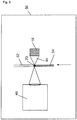
Fig. 5 is a schematic diagram of an embodiment featuring a capillary tube sample vessel and cartridge docking. - As used throughout this application, the term "magnetic particles" shall be defined as conventional magnetic particles, paramagnetic particles, superparamagnetic particles or any other particle which is affected by a magnetic field. In some embodiments, advantages may be realized by having magnetic capture and concentration apparatus integrated with a spectrometer or other optical interrogation device. For example a fully integrated capture, concentration and imaging system minimizes the possibility of the misplacement or de-compaction of a pellet of concentrated magnetic particles since the sample vessel does not have to be moved between the concentration and optical interrogation steps. Accordingly, such integrated apparatus embodiments are described in detail below.
- Although a spherical magnet is shown in
Fig. 5 , any other suitable shape and relative size of magnets, which may be either permanent magnets or electromagnets, are equally suitable for implementation of the present invention. For example, a linear magnet may be used to provide for a linear pellet which may be scanned along a length. In addition, it may be desired in certain implementations to modify the profile of the magnetic field generated by using a combination of a magnet plus a "pole piece" constructed from an appropriate ferromagnetic material, for example, steel alloys or other suitable materials known to those skilled in the art. This approach can be used to optimise the magnetic field pattern for the purpose of concentration and localisation of magnetic particles. - Additionally, capillay tubes (52) having any number of customized shapes may be used to effectively implement the apparatus. The customized shape might include a protrusion or indentation or other structure or form at or near the
magnetic concentration region 20 described above. The customized shape may affect the nature of the pellet formed in the concentration step. The development of a concentrated, well-formed, and consistent magnetic pellet from magnetic capture particles and associated optical labels is a function of the magnetic field architecture as well as the sample tube morphology at themagnetic concentration region 20. Thus, the size and shape of the concentrated pellet can be altered by altering the shape of the surface the magnetic capture particles are collected upon or within. Therefore, customized tube architecture with a dimple (or cusp) or other shaped structure or form at or near the magnetic concentration region could aid in the formation of a magnetic pellet having reproducible size, shape and consistency. For example, a concave cusp may be utilized to form a spherical pellet at the bottom or side of a customized collection vessel. - The material of the capillay tubes (52) must be compatible with the reagents and analyte substances intended for use in the assay. Certain chemical or biological coatings may be applied to the vessel to prevent non specific binding of magnetic particles, optical tag or analyte to the vessel walls. The capillay tube (52) should be constructed of a non-magnetic material, such that a magnetic field applied from an external source passes through the capillay tube (52) unaffected. Furthermore, it should be designed such that consideration is given to the maximum distance that would be travelled by reagents to the localisation spot. This governs the speed and efficacy of magnetic capture, since the attractive force decreases rapidly as the distance from the magnet system is increased.
- The form of the capillay tube (52) may include external geometric features, markers or indicia 22, to enhance the repeatability of positioning, and prevent incorrect vessel insertion within the holder apparatus. Positioning features could include (but are not limited to) the inclusion of flat sections, keyways, fiducial points etc. These would match similar features in a specifically designed vessel receptacle associated with magnetic localisation, spectroscopic measurement or combination of these functions, all as described herein.
- In embodiments where assay interrogation is performed optically, typically a select laser output is applied to the concentrated pellet. Thus the capillay tube (52) should be appreciably transparent in the desired laser interrogation wavelength region. Moreover, it is desirable to ensure that the localising region has optical properties compatible with the lens system of the spectrometer or other detection device. Flat optical surfaces that allow the entry and exit of excitation and emitted light with minimal refraction, reflection or scattering may be desired. Alternatively, surfaces with curvature in one or more dimensions intended to function as lenses may be beneficial. Furthermore, the vessel design should allow the simultaneous presence of a magnetic localising system and operation of the spectrometer in the case where both functions are included in one instrument. The
magnetic concentration region 20 can be at any position on the capillay tube (52) conducive to the ability to concentrate and localise the assay reagents and make optical measurements. - The various embodiments described herein are particularly advantageous for the concentration of magnetic capture particles associated with SERS nanotags or similar SERS taggants as the optically labeled detection particles. SERS nanotags have a SERS active core associated with a Raman reporter molecule which may be interrogated through Raman spectroscopy. Accordingly, it is useful in any implementation of the present invention which features Raman spectroscopy that the material of the capillay tube (52) be transparent to Raman light scatter. The primary limitation with respect to Raman spectroscopy is that the capillay tube (52) wall not interfere through absorption both at the laser excitation wavelengths, including, but not limited to, 633nm or 785 nm wavelengths, as well as the subsequent Raman emission wavelengths. Indeed, an ideal material would also not contribute Raman interference and/or fluorescence at these excitation wavelengths, as well. A wide variety of inexpensive and commonly used assay tubes meet this criteria.
-
Graph 46 ofFig. 1 illustrates the progress of pellet formation during magnetic concentration as a function of time, as determined by the signal from SERS labels attached to magnetic beads in an immunological reaction scheme. It is desirable for spectroscopic analysis that the pellet size be as small as possible, since an appreciable part of the volume of captured particles may otherwise fall outside the laser illumination spot presented by typical instruments, which is generally a diameter of about 70 to 200 microns. It is also desirable that the pellet size be as small as possible for a given number of magnetic beads. This has multiple advantages. First, a dense pellet results in a smaller sampling area. In traditional spectroscopic capture, a smaller sampling area allows matching to a smaller spectrometer slit resulting in a higher spectral resolution for a given etendue (optical throughput). In addition, a denser pellet results in a higher signal-to-noise ratio as there will be a larger number of tags per unit sampling volume. A denser pellet should also improve sample-to-sample variance as a smaller pellet should match better to both the laser spot and optical collection area. Thus a collection area which is slightly larger than the pellet, should be relatively immune to signal variations from minor shape differences between pellets. Finally, a dense pellet of magnetic beads aids in obscuring the larger volume of solution, containing unbound optical label. This mechanism of obscuration could lower the detection floor, thus increasing sensitivity and leading to an improvement in the dynamic range of the test. - Pellet formation can be achieved with a static positioning between the capillay tube (52) and
magnet 18. However, the magnetic particles may be concentrated to a smaller volume if themagnet 18 is moved relative to the surface of the sample vessel - a displacement of less than 1mm is sufficient to achieve measurable concentration improvement. Movement of themagnet 18, however, may be impractical, due to the requirement that the position of themagnetic concentration zone 20 be in coincidence with the laser illumination from thespectrometer 40. It is possible to stimulate tight pellet formation however, by use of techniques or methods including but not limited to mechanical, acoustic or magnetic stimulation of the capillay tube (52). Vibrational energy is sufficient to dislodge particles that have become stuck to the vessel wall before reaching the final position of lowest potential energy nearest themagnet 18 ormagnetic pole piece 44. Practical methods by which this may be achieved include but are not limited to the following: Momentary vibration of the holder 12; momentary vibration of the capillay tube (52) within the sample holder 12; momentary exposure of the capillay tube (52) and contents to a high pressure acoustic wave; or the application of a moving or oscillating magnetic field, such as from an electromagnet. These methods introduce enough perturbation to facilitate the formation of a lowest energy state dense pellet. In addition, there is the further option of causing the pellet to reform by manipulation of the capillay tube (52) in order that the pellet is forced to re-form at a different location on the vessel wall 24, e.g. by removal of the tube from the magnetic field and its replacement at an alternative orientation, or by removal and reapplication of themagnet 18 or magnets at a different location on the capillay tube (52). -
Figures 2A-C schematically illustrate three representative and non-exclusive processes for compact pellet formation. In each case, step (a) is the initial capture of reagents from the starting point of complete dispersion in the assay fluid, step (b) is the completion of initial capture and pellet formation and step (c) involves forcing the pellet to reform and concentrate at a second capture point without significant redispersion. This can be achieved by: - A single or combination of multiple permanent magnets that are moved in relation to the sample vessel in order to effect the desired pellet formation & manipulation. (
Fig. 2A ) - A combination of electromagnets to achieve the same effect. (
Fig. 2B ) - Mechanical adjustment of the tube position in the receptacle, for example 180° rotation of a cylindrical sample vessel to force pellet repositioning. (
Fig. 2C ) - In certain embodiments of an integrated capture/interrogation unit it may be challenging to design a magnetic assembly which generates a strong enough magnetic field to pull magnetic particles down through the assay solution, to form a suitable pellet, and also provide clearance for the optical read-out. Thus, it may be advantageous to have magnetic concentration happen on one side of the capillay tube (52) while optical readout happens on the opposite side of the vessel. In such an embodiment, any curvature of the capillay tube (52) plus optical effects of assay components contained therein may act as an optical element. It is desirable as described above to achieve a small illumination spot and collection area. Accordingly, the optical system associated with the
spectrometer 40 may be designed to compensate for the optical effects of the capillay tube (52). - Although the embodiments of
Figs. 3-5 show single capillay tubes (52), high throughput parallel assays can easily be prepared and performed by using multiple parallel assay capillay tubes holders and magnets. The magnetic concentrator step and readout could occur in parallel or serially. - A ½" spherical NdFeB (rare-earth) magnet has been successfully used experimentally to create a pellet of magnetic beads and associated SERS tags in a single pull-down step. The capillay tube (52) used was a 200uL polypropylene microcentrifuge tube with 100uL or less of reagent. As shown on
graph 46 ofFig. 1 , adequate pull-down of particles leading to a relatively steady state optical signal was achieved in less than one minute. - In an alternative assay system embodiment, a whole pellet may be imaged using a tunable filter (LCTF, AOTF, etc.) to create a hyper-spectral image stack. If consistent pellet formation proves to be difficult, imaging the whole pellet combined with subsequent image analysis could provide a metric for a "total optical label" that is consistent without respect to the distribution or shape of the pellet.
- Similarly, a diffuse pellet, for example a linear pellet formed by a linear magnet, could be adequate for a reproducible, homogeneous, magnetic pull-down assay if spatial information is captured by the means of a scanning or wide-field imaging system. In this embodiment, the pellet may be imaged and a software analysis step employed to determine a metric for the total signal (for example the SERS signal) emitted by each pellet. This implementation shares features with DNA microarray readers commonly available, except for the need for a relatively large number of spectral channels (i.e. hyperspectral imaging). Nonetheless, for a high-throughput system utilizing a microplate configuration with multiple wells, this could offer benefits. Optical resolution, on the order of 50um, could be adequate to allow an image processing algorithm to account for pellet size and shape differences to obtain a consistent total signal metric across replicate pellets. Prior research shows that a minimum number of spectral channels (∼20-30 spectral channels), could be adequate to differentiate and quantitate SERS tags. In a wide-field embodiment this may provide for the use of liquid-crystal tunable filters (LCTF), or acousto-optical tunable filters (AOTF) to achieve spectral separation. With respect to a laser-point scanning system, a low spectral resolution dispersive spectrometer system could be adequate.
- In a high-throughput detection system it may be preferable to separate the magnetic concentration step from the optical read step. Magnetic concentration freezes the chemical reaction and so all samples in a batch would require that their pellets be formed at the same time. Large process volumes may result in variation in the exact location of each pellet. One possibility to address this issue for high-throughput geometry, therefore, is to use an initial imaging step, not to gather spectral information, but merely to locate the pellets. An image processing step could extract the positions of all the pellets and use this information to position a conventional point spectrometer system under each pellet sequentially.
- High throughput apparatus could be fabricated in which the capillay tubes are discrete tubes. The tubes could be transported within the apparatus to various function "stations" by a conveyor track, belt or robotic system. The precise location and timing of each sample tube could be tracked by a microprocessor system that controls the apparatus function, enabling precise control of reaction timings, temperatures, mixing and measurement etc. Such an apparatus for the invention might include provision for process steps including but not limited to
- Delivery of reagents, analyte to the sample vessel.
- Control of vessel temperature and reaction time.
- Localisation of the assay components by application of a magnetic field.
- Optimisation of the pellet formation by methods described previously.
- Optical measurement of the localised reagents within the vessel.
- The sequence of steps could include the methods of localisation separate from, or coincident with making optical measurements, in the same manner as described already, thus the high throughput apparatus would incorporate receptacles for the vessels that have magnet assemblies for localisation, and/or spectrometers operatively associated with magnet assemblies. Other variations upon the basic high throughput apparatus described herein are within the scope of this disclosure.
- In some embodiments, a small bead composed of a material of high magnetic permeability (e.g. nickel, cobalt, etc) may be placed in the reaction vessel. The presence of the high-permeability bead will focus the magnetic field lines thus creating a high magnetic field gradient to attract the magnetic particles. The magnetic particle / assay tag complex could associate around the bead and the whole large assembly, consisting of a large "bead" with the surrounding small magnetic particles and assay tags would be imaged. This technique could assist in achieving a reproducible spherical pellet for optimal interrogation.
- In certain embodiments it may be desirable in either a nominal or high throughput system to eliminate the need for pellet re-forming or conditioning. One suitable apparatus for use without pellet conditioning is schematically illustrated in
Figs. 3 and4 . Theapparatus 50 includes acapillary tube 52. Thecapillary tube 52 is in fluid communication with anassay particle suspension 54. As theparticle suspension 54 flows through thecapillary tube 52, magnetic particles are concentrated within thetube 52 by acapture magnet 18 which may or may not be associated with apole piece 44. Thecapture magnet 18 serves to concentrate magnetic particles at a specificmagnetic concentration region 20 within thecapillary tube 52. A spectrometer or other interrogation device which may be aRaman spectrometer 40 is operatively associated with thecapillary tube 52 and focused upon themagnetic concentration region 20. As shown inFigs. 3 and4 , optical interrogation may occur along an optical path which is opposite from or merely offset from the magnetic axis. - The use of a
capillary tube 52 as a sample vessel provides several distinct advantages including but are not limited to: - Precise placement of magnetic particles in relation to the small area interrogated by a typical laser based system. This will potentially improve the accuracy of measurement where quantitative determination is required.
- The sampling vessel has inherently high optical quality. For example, the
capillary tube 52 may have flat sides and be made of a material which is transparent at the necessary wavelengths. Thecapillary tube 52 is also potentially fixed in a location relative to the magnetic and optical components. - A
capillary tube apparatus 50 allows tests to be conducted with small sample volumes of less than 100 microlitres and small reagent quantities which may result in improved sensitivity. - A
capillary tube apparatus 50 permits rapid collection of a sample pellet with no conditioning required. The pellet is contained in a small area and is inherently tightly packed. The magnetic element is not required to provide attractive forces at great distance since the capillary tube wall and magnetic pole are arranged in close registration (for example, with a separation of not more than 1mm). This is advantageous since the attractive force experienced by magnetic particles falls rapidly with increasing distance from the pole orpole piece 44 of a magnet system. - The volume of fluid interrogated by the reader is reduced significantly by the use of a narrow capillary vessel. Hence the quantity of unbound tag, which would otherwise contribute an unwanted "background signal" may be made very small.
- Use of electromagnets in the capture mechanism may allow collection of magnetic particles at the concentration region and subsequent flushing of particles from this region. In this way the vessel could be used serially to read from multiple sample assay reactions. This could operate on demand, or semi-continuously as part of a larger automated system in which many tests are run in sequence.
- A
capillary tube apparatus 50 could also be used to implement a lateral flow assay device. In a lateral flow assay embodiment, a capillary tube associated with a magnet replaces the typical cellulose fiber strip or other matrix. A reservoir or reservoir pad containing adsorbed reagents (for example: SERS tags and magnetic particles) may be arranged in communication with one opening in the capillary tube. Introduction of analyte fluid to the reservoir results in release of the particulate reagents, which are caused to flow along the capillary with the analyte in solution. The magnet traps magnetic particles at a precisely defined location. Any tags such as SERS particles attached to magnetic particles may be detected by means of a Raman spectrometer directed at the capture point. Precise location of the capture point in relation to the spectrometer may be effected through the magnet system. - The capillary tube-based lateral flow embodiment described immediately above is suitable for use as an integrated assay system which could if desired be developed in a very compact form factor for highly accurate and repeatable field assay usage. An
integrated system 60 consistent with this embodiment is schematically illustrated inFig. 5 . In theFig. 5 embodiment, thecapillary tube 52 is mounted in asample cartridge 62. Thecapillary tube 52 is in communication with asample reservoir 64 formed in thesample cartridge 62. Theassay particle suspension 54 necessary to perform an assay including magnetic particles and reagents may be mixed in thesample reservoir 64. Since thesample reservoir 64 is in fluid communication with thecapillary tube 52, fully reactedassay suspension 54 is readily drawn toward themagnetic concentration region 20 by capillary action. In addition, excess assay particles are wicked away from themagnetic concentration region 20 minimizing background signal. At themagnetic capture region 20, amagnet 18 will concentrate magnetic particles as described above at the focal plane of aspectrometer 40 where optical interrogation of the concentrated sample may occur. - The
integrated system 60 ofFig. 5 may be fabricated with acartridge docking receptacle 66 configured to accurately receive and position thecartridge 62 so that themagnetic capture region 20 is properly aligned. Thesystem 60 may also includedata processing elements 68 associated with the spectrometer that enable theapparatus 60 to be used as a portable and potentially handheld stand-alone assay device.
Claims (13)
- An assay apparatus (60) comprising:a capillary tube (52);a sample reservoir (64);a sample cartridge (62) in which the sample reservoir (64) is formed and in which the capillary tube (52) is mounted, whereby the capillary tube (52) is in fluid communication with the reservoir (64);a holder (66) configured to receive the sample cartridge (62);a magnet (18) operatively associated with the holder (66) such that a magnetic field intersects with a portion of the capillary tube (52) defining a magnetic concentration region (20) within the capillary tube (52); anda spectrometer (40) operatively associated with the holder (66) such that the focus of the spectrometer (40) is within the magnetic concentration region (20).
- The assay apparatus of claim 1, wherein the spectrometer (40) is a Raman spectrometer.
- The assay apparatus of any one of claims 1 or 2, further comprising means to stimulate compact concentration operatively associated with the capillary tube (52);
preferably wherein the means to stimulate compact concentration is selected from a group consisting of an electromagnetic stimulator; a vibrator; an acoustic transducer and a mechanical agitator. - The assay apparatus of any one of claims 1 to 3, wherein the magnet (18) and the spectrometer (40) are positioned to minimize the quantity of assay fluid outside of the magnetic concentration region (20) but within an optical path between the spectrometer (40) and the magnetic concentration region (20).
- The assay apparatus of any one of claims 1 to 4, wherein the magnet (18) is positioned to cause the magnetic concentration region (20) to be formed substantially adjacent to a location where an optical path between the spectrometer (40) and the magnetic concentration region (20) initially intersects the interior of the capillary tube (52).
- The assay apparatus of any one of claims 1 to 5, wherein the capillary tube (52) further comprises an internal wall wherein a portion of the internal wall which is initially intersected by an optical path from the spectrometer (40) defines an interface and wherein the magnetic concentration region (20) is formed substantially adjacent to the interface.
- A method of performing an assay comprising:associating magnetic capture particles with detection particles in a capillary tube (52) of a sample cartridge (62) in which a sample reservoir (64) is formed and in which the capillary tube (52) is mounted, whereby the capillary tube (52) is in fluid communication with the reservoir (64);placing the sample cartridge (62) in a holder (66) configured to receive the sample cartridge (62) and hold it in a select relationship with a magnet (18) and a spectrometer (40) associated with the holder;magnetically concentrating the magnetic capture particles in a concentration region (20) of the capillary tube (52) such that the focus of the spectrometer (40) is within the magnetic concentration region (20);and obtaining a spectrum from the magnetic concentration region (20).
- The method of claim 7 wherein the spectrum obtained from the magnetic concentration region (20) is a Raman spectrum, preferably wherein the Raman spectrum is obtained from a SERS taggant associated with the magnetic capture particles in the magnetic concentration region (20).
- The method of performing an assay of any one of claims 7 to 8 further comprising stimulating compact concentration of the magnetic capture particles in the concentration region (20);
preferably wherein the stimulation step comprises at least one of mechanically agitating the capillary tube (52); vibrating the capillary tube (52) ; projecting acoustic wave through the capillary tube (52) and passing a moving magnetic field through a portion of the capillary tube (52). - The method of performing an assay according to any one of claims 7 to 9 wherein the magnet (18) and the spectrometer (40) are positioned to minimize the quantity of assay fluid outside of the magnetic concentration region (20) but within an optical path between the spectrometer (40) and the magnetic concentration region (20).
- The method of performing an assay according to any one of claims 7 to 10 wherein the magnet (18) is positioned to cause the magnetic concentration region (20) to be formed substantially adjacent to a location where an optical path between the spectrometer (40) and the magnetic concentration region (20) initially intersects the interior of the capillary tube (52).
- The method of performing an assay according to any one of claims 7 to 11 wherein the capillary tube (52) further comprises an internal wall wherein a portion of the internal wall which is initially intersected by an optical path from the spectrometer (40) defines an interface and wherein the magnetic concentration region (20) is formed substantially adjacent to the interface.
- The method of performing an assay according to any one of claims 9 to 12 wherein the stimulation step comprises at least one of repositioning the capillary tube (52) with respect to the magnet (18); repositioning the magnet (18) with respect to the capillary tube (52) and applying a magnetic field from more than one magnet (18) to the capillary tube (52).
Applications Claiming Priority (4)
| Application Number | Priority Date | Filing Date | Title |
|---|---|---|---|
| US83292106P | 2006-07-24 | 2006-07-24 | |
| US91024607P | 2007-04-05 | 2007-04-05 | |
| US91025607P | 2007-04-05 | 2007-04-05 | |
| EP07799772.4A EP2044402B2 (en) | 2006-07-24 | 2007-07-24 | Apparatus and method for performing an assay using magnetic particles |
Related Parent Applications (3)
| Application Number | Title | Priority Date | Filing Date |
|---|---|---|---|
| EP07799772.4A Division EP2044402B2 (en) | 2006-07-24 | 2007-07-24 | Apparatus and method for performing an assay using magnetic particles |
| EP07799772.4A Division-Into EP2044402B2 (en) | 2006-07-24 | 2007-07-24 | Apparatus and method for performing an assay using magnetic particles |
| EP07799772.4 Division | 2007-07-24 |
Publications (2)
| Publication Number | Publication Date |
|---|---|
| EP2620771A1 EP2620771A1 (en) | 2013-07-31 |
| EP2620771B1 true EP2620771B1 (en) | 2017-08-30 |
Family
ID=38982246
Family Applications (2)
| Application Number | Title | Priority Date | Filing Date |
|---|---|---|---|
| EP07799772.4A Active EP2044402B2 (en) | 2006-07-24 | 2007-07-24 | Apparatus and method for performing an assay using magnetic particles |
| EP13164976.6A Active EP2620771B1 (en) | 2006-07-24 | 2007-07-24 | Assay particle concentration apparatus and method |
Family Applications Before (1)
| Application Number | Title | Priority Date | Filing Date |
|---|---|---|---|
| EP07799772.4A Active EP2044402B2 (en) | 2006-07-24 | 2007-07-24 | Apparatus and method for performing an assay using magnetic particles |
Country Status (5)
| Country | Link |
|---|---|
| US (1) | US20100060893A1 (en) |
| EP (2) | EP2044402B2 (en) |
| JP (1) | JP5277165B2 (en) |
| ES (2) | ES2422295T5 (en) |
| WO (1) | WO2008014223A2 (en) |
Families Citing this family (22)
| Publication number | Priority date | Publication date | Assignee | Title |
|---|---|---|---|---|
| CA2738317C (en) * | 2008-09-24 | 2020-01-14 | Straus Holdings Inc. | Imaging analyzer for testing analytes |
| US8427641B2 (en) * | 2008-12-18 | 2013-04-23 | Azbil BioVigilant, Inc. | Compact detector for simultaneous particle size and fluorescence detection |
| US8828729B1 (en) | 2009-01-28 | 2014-09-09 | Cabot Corporation | Methods and apparatus for the detection of taggants by surface enhanced raman scattering |
| US20140106336A1 (en) * | 2010-12-07 | 2014-04-17 | Colorado School Of Mines | Detection of Magnetic-Field-Concentrated Analytes in a Lateral Flow Capillary |
| US8624199B2 (en) | 2011-10-28 | 2014-01-07 | Fei Company | Sample block holder |
| USD690826S1 (en) | 2012-04-12 | 2013-10-01 | Becton Dickinson And Company | Vessel assembly |
| CA2869732C (en) | 2012-04-12 | 2018-04-03 | Kristin Weidemaier | Methods, systems, and devices for detecting and identifying microorganisms in microbiological culture samples |
| US8664595B2 (en) | 2012-06-28 | 2014-03-04 | Fei Company | Cluster analysis of unknowns in SEM-EDS dataset |
| US9188555B2 (en) | 2012-07-30 | 2015-11-17 | Fei Company | Automated EDS standards calibration |
| US9778215B2 (en) | 2012-10-26 | 2017-10-03 | Fei Company | Automated mineral classification |
| US8937282B2 (en) | 2012-10-26 | 2015-01-20 | Fei Company | Mineral identification using mineral definitions including variability |
| US9091635B2 (en) | 2012-10-26 | 2015-07-28 | Fei Company | Mineral identification using mineral definitions having compositional ranges |
| US9048067B2 (en) | 2012-10-26 | 2015-06-02 | Fei Company | Mineral identification using sequential decomposition into elements from mineral definitions |
| US9194829B2 (en) | 2012-12-28 | 2015-11-24 | Fei Company | Process for performing automated mineralogy |
| EP3859301A1 (en) | 2014-02-11 | 2021-08-04 | Wallac OY | A device and a method for managing a sample to be analyzed and a solid sample carrier and liquid sample carrier |
| ITUB20154940A1 (en) * | 2015-11-06 | 2017-05-06 | Disa Raffaele E F Lli S A S | Cell for analysis by Raman spectroscopy. |
| KR20180128424A (en) | 2016-03-18 | 2018-12-03 | 앤드류 알리안스 에스. 에이. | Method and apparatus for manipulating beads in tip of liquid handler |
| US20200209235A1 (en) * | 2017-06-20 | 2020-07-02 | Salus Discovery, LLC | Lateral flow devices and methods |
| GB201818412D0 (en) * | 2018-11-12 | 2018-12-26 | Lumiradx Tech Ltd | A magnetic assembly for use in a device for conducting assays |
| US11480565B2 (en) | 2020-06-12 | 2022-10-25 | Bio-Rad Laboratories, Inc. | Automated immunoassay |
| WO2023198908A1 (en) * | 2022-04-15 | 2023-10-19 | Quantoom Biosciences S.A. | Device and method for the separation and/or purification of a compound of interest |
| BE1030466B1 (en) * | 2022-04-20 | 2023-11-21 | Quantoom Biosciences S A | DEVICE AND METHOD FOR THE SEPARATION AND/OR PURIFICATION OF A COMPOUND OF INTEREST |
Citations (1)
| Publication number | Priority date | Publication date | Assignee | Title |
|---|---|---|---|---|
| US5238810A (en) * | 1986-09-22 | 1993-08-24 | Nippon Telegraph And Telephone Corporation | Laser magnetic immunoassay method and apparatus thereof |
Family Cites Families (87)
| Publication number | Priority date | Publication date | Assignee | Title |
|---|---|---|---|---|
| US4039297A (en) * | 1971-12-25 | 1977-08-02 | Japanese National Railways | Heat insulating particles |
| GB1452271A (en) * | 1972-10-23 | 1976-10-13 | English Clays Lovering Pochin | Apparatus for use in separating magnetic particles from a fluid in which they are suspended |
| US3975084A (en) * | 1973-09-27 | 1976-08-17 | Block Engineering, Inc. | Particle detecting system |
| NL7807532A (en) * | 1978-07-13 | 1980-01-15 | Akzo Nv | METAL IMMUNO TEST. |
| GB8415998D0 (en) * | 1984-06-22 | 1984-07-25 | Janssen Pharmaceutica Nv | Staining method |
| US5059394A (en) * | 1986-08-13 | 1991-10-22 | Lifescan, Inc. | Analytical device for the automated determination of analytes in fluids |
| JPS63106559A (en) * | 1986-10-23 | 1988-05-11 | Nippon Telegr & Teleph Corp <Ntt> | Method and apparatus for laser magnetic immunoassay |
| US4802761A (en) * | 1987-08-31 | 1989-02-07 | Western Research Institute | Optical-fiber raman spectroscopy used for remote in-situ environmental analysis |
| US4853335A (en) * | 1987-09-28 | 1989-08-01 | Olsen Duane A | Colloidal gold particle concentration immunoassay |
| JP2551627B2 (en) * | 1988-04-26 | 1996-11-06 | 日本電信電話株式会社 | Laser magnetic immunoassay device |
| US5238811A (en) * | 1988-04-26 | 1993-08-24 | Nippon Telegraph And Telephone Corporation | Laser magnetic immunoassay method and apparatus therefor and superparamagnetic material-labeled body and method for the manufacture of same |
| US5096809A (en) * | 1988-07-25 | 1992-03-17 | Pacific Biotech, Inc. | Whole blood assays using porous membrane support devices |
| US5023139A (en) * | 1989-04-04 | 1991-06-11 | Research Corporation Technologies, Inc. | Nonlinear optical materials |
| DE3934351A1 (en) * | 1989-10-14 | 1991-04-18 | Studiengesellschaft Kohle Mbh | METHOD FOR PRODUCING MICROCRYSTALLINE TO AMORPHOUS METAL OR ALLOY POWDER AND WITHOUT PROTECTIVE COLLOID IN ORGANIC SOLVENTS SOLVED METALS OR. ALLOYS |
| US5112127A (en) * | 1989-11-28 | 1992-05-12 | Eic Laboratories, Inc. | Apparatus for measuring Raman spectra over optical fibers |
| US5255067A (en) * | 1990-11-30 | 1993-10-19 | Eic Laboratories, Inc. | Substrate and apparatus for surface enhanced Raman spectroscopy |
| JPH04348277A (en) * | 1991-05-24 | 1992-12-03 | Nippon Paint Co Ltd | Method and apparatus for measuring in-vivo substance |
| US6200820B1 (en) * | 1992-12-22 | 2001-03-13 | Sienna Biotech, Inc. | Light scatter-based immunoassay |
| US5384265A (en) * | 1993-03-26 | 1995-01-24 | Geo-Centers, Inc. | Biomolecules bound to catalytic inorganic particles, immunoassays using the same |
| US5637508A (en) * | 1993-03-26 | 1997-06-10 | Geo-Centers, Inc. | Biomolecules bound to polymer or copolymer coated catalytic inorganic particles, immunoassays using the same and kits containing the same |
| JPH06300762A (en) * | 1993-04-14 | 1994-10-28 | Nippon Telegr & Teleph Corp <Ntt> | Non-separate type apparatus for fluorescent immunoassay |
| US5441894A (en) * | 1993-04-30 | 1995-08-15 | Abbott Laboratories | Device containing a light absorbing element for automated chemiluminescent immunoassays |
| CA2164725A1 (en) * | 1993-06-08 | 1994-12-22 | Alexander Saunders | Two-phase optical assay method and apparatus |
| ZA948782B (en) * | 1993-11-12 | 1996-05-07 | Unipath Ltd | Reading devices and assay devices for use therewith |
| US7141212B2 (en) * | 1993-11-12 | 2006-11-28 | Inverness Medical Switzerland Gmbh | Reading devices and assay devices for use therewith |
| JP3115501B2 (en) * | 1994-06-15 | 2000-12-11 | プレシジョン・システム・サイエンス株式会社 | Method for controlling desorption of magnetic material using dispenser and various devices processed by this method |
| US6451619B1 (en) * | 1994-06-29 | 2002-09-17 | Inverness Medical Switzerland Gmbh | Monitoring methods and devices for use therein |
| US5891738A (en) * | 1995-01-16 | 1999-04-06 | Erkki Soini | Biospecific multiparameter assay method |
| AU4927496A (en) * | 1995-02-21 | 1996-09-11 | Iqbal W. Siddiqi | Apparatus and method for mixing and separation employing magnetic particles |
| JPH09218201A (en) * | 1995-12-07 | 1997-08-19 | Seiko Instr Inc | Method for separating magnetic particle |
| US5833924A (en) * | 1995-12-22 | 1998-11-10 | Universal Healthwatch, Inc. | Sampling-assay device and interface system |
| US6750031B1 (en) * | 1996-01-11 | 2004-06-15 | The United States Of America As Represented By The Secretary Of The Navy | Displacement assay on a porous membrane |
| US6027890A (en) * | 1996-01-23 | 2000-02-22 | Rapigene, Inc. | Methods and compositions for enhancing sensitivity in the analysis of biological-based assays |
| AUPN825796A0 (en) * | 1996-02-26 | 1996-03-14 | Ashdown, Martin | The application of infrared (ir) spectrometry to the investigations of components of blood and other body fluids |
| US6103868A (en) * | 1996-12-27 | 2000-08-15 | The Regents Of The University Of California | Organically-functionalized monodisperse nanocrystals of metals |
| US5958704A (en) * | 1997-03-12 | 1999-09-28 | Ddx, Inc. | Sensing system for specific substance and molecule detection |
| US5998224A (en) * | 1997-05-16 | 1999-12-07 | Abbott Laboratories | Magnetically assisted binding assays utilizing a magnetically responsive reagent |
| AU8261098A (en) * | 1997-06-24 | 1999-01-04 | University Of Wyoming | Method and apparatus for detection of a controlled substance |
| US5864397A (en) * | 1997-09-15 | 1999-01-26 | Lockheed Martin Energy Research Corporation | Surface-enhanced raman medical probes and system for disease diagnosis and drug testing |
| US6060256A (en) * | 1997-12-16 | 2000-05-09 | Kimberly-Clark Worldwide, Inc. | Optical diffraction biosensor |
| US6020207A (en) * | 1998-06-17 | 2000-02-01 | World Precision Instruments, Inc. | Optical analysis technique and sensors for use therein |
| US6226082B1 (en) * | 1998-06-25 | 2001-05-01 | Amira Medical | Method and apparatus for the quantitative analysis of a liquid sample with surface enhanced spectroscopy |
| US6136610A (en) * | 1998-11-23 | 2000-10-24 | Praxsys Biosystems, Inc. | Method and apparatus for performing a lateral flow assay |
| US6150182A (en) † | 1998-11-30 | 2000-11-21 | Cassaday; Michael M. | Method for separation of components in a biochemical reaction utilizing a combination of magnetic and centrifugal processes |
| EP1151139A2 (en) * | 1999-01-25 | 2001-11-07 | UT-Battelle, LLC | Multifunctional and multispectral biosensor devices and methods of use |
| DE60041255D1 (en) * | 1999-04-28 | 2009-02-12 | Eidgenoess Tech Hochschule | POLYIONIC COATINGS FOR ANALYTICAL AND SENSOR DEVICES |
| ATE439452T1 (en) * | 1999-05-07 | 2009-08-15 | Life Technologies Corp | METHOD FOR DETECTING ANALYTES USING SEMICONDUCTOR NANOCRYSTALS |
| US7123359B2 (en) * | 1999-05-17 | 2006-10-17 | Arrowhead Center, Inc. | Optical devices and methods employing nanoparticles, microcavities, and semicontinuous metal films |
| AU5248600A (en) * | 1999-06-15 | 2001-01-02 | Kimoto, Masaaki | Ultrafine composite metal powder and method for producing the same |
| US7105310B1 (en) * | 2000-07-19 | 2006-09-12 | California Institute Of Technology | Detection of biomolecules by sensitizer-linked substrates |
| EP1072887B1 (en) * | 1999-07-30 | 2005-11-16 | Mitsubishi Chemical Corporation | Immunoassay |
| US6422998B1 (en) * | 1999-09-20 | 2002-07-23 | Ut-Battelle, Llc | Fractal analysis of time varying data |
| US6254830B1 (en) * | 1999-11-05 | 2001-07-03 | The Board Of Governors For Higher Education, State Of Rhode Island And Providence Plantations | Magnetic focusing immunosensor for the detection of pathogens |
| US6645777B1 (en) * | 1999-11-05 | 2003-11-11 | The Board Of Governors For Higher Education, State Of Rhode Island And Providence Plantation | Tapered tubular optical waveguide probe for magnetic focusing immunosensors |
| US6587197B1 (en) * | 1999-12-06 | 2003-07-01 | Royce Technologies Llc | Multiple microchannels chip for biomolecule imaging, and method of use thereof |
| CA2403708A1 (en) * | 2000-03-22 | 2001-09-27 | Quantum Dot Corporation | Methods of using semiconductor nanocrystals in bead-based nucleic acid assays |
| US6734420B2 (en) * | 2000-04-06 | 2004-05-11 | Quantum Dot Corporation | Differentiable spectral bar code methods and systems |
| AU2001250287B2 (en) * | 2000-04-11 | 2005-06-23 | Chemometec A/S | Method and apparatus for detecting fluorescence of a sample |
| US6610351B2 (en) * | 2000-04-12 | 2003-08-26 | Quantag Systems, Inc. | Raman-active taggants and their recognition |
| WO2001083823A1 (en) * | 2000-04-28 | 2001-11-08 | Quantum Dot Corporation | Methods and compositions for polynucleotide analysis using generic capture sequences |
| US6649138B2 (en) * | 2000-10-13 | 2003-11-18 | Quantum Dot Corporation | Surface-modified semiconductive and metallic nanoparticles having enhanced dispersibility in aqueous media |
| US20020083888A1 (en) * | 2000-12-28 | 2002-07-04 | Zehnder Donald A. | Flow synthesis of quantum dot nanocrystals |
| WO2003092043A2 (en) * | 2001-07-20 | 2003-11-06 | Quantum Dot Corporation | Luminescent nanoparticles and methods for their preparation |
| US6972173B2 (en) * | 2002-03-14 | 2005-12-06 | Intel Corporation | Methods to increase nucleotide signals by raman scattering |
| US6562403B2 (en) * | 2001-10-15 | 2003-05-13 | Kansas State University Research Foundation | Synthesis of substantially monodispersed colloids |
| US6778316B2 (en) * | 2001-10-24 | 2004-08-17 | William Marsh Rice University | Nanoparticle-based all-optical sensors |
| US7102752B2 (en) * | 2001-12-11 | 2006-09-05 | Kimberly-Clark Worldwide, Inc. | Systems to view and analyze the results from diffraction-based diagnostics |
| US7098041B2 (en) * | 2001-12-11 | 2006-08-29 | Kimberly-Clark Worldwide, Inc. | Methods to view and analyze the results from diffraction-based diagnostics |
| US20040021073A1 (en) * | 2002-04-12 | 2004-02-05 | California Institute Of Technology | Apparatus and method for magnetic-based manipulation of microscopic particles |
| JP3983593B2 (en) * | 2002-04-26 | 2007-09-26 | プレシジョン・システム・サイエンス株式会社 | Magnetic particle suspension measuring device |
| US20030211488A1 (en) * | 2002-05-07 | 2003-11-13 | Northwestern University | Nanoparticle probs with Raman spectrocopic fingerprints for analyte detection |
| US7122384B2 (en) * | 2002-11-06 | 2006-10-17 | E. I. Du Pont De Nemours And Company | Resonant light scattering microparticle methods |
| CN100538362C (en) * | 2002-11-07 | 2009-09-09 | 株式会社三菱化学药得论 | Be used to collect the magnetic material and the application thereof of magnetic-particle |
| US7695738B2 (en) * | 2003-02-19 | 2010-04-13 | Academia Sinica | Carbohydrate encapsulated nanoparticles |
| US7239394B2 (en) * | 2003-06-04 | 2007-07-03 | Inverness Medical Switzerland Gmbh | Early determination of assay results |
| US7317532B2 (en) * | 2003-06-04 | 2008-01-08 | Inverness Medical Switzerland Gmbh | Flow sensing for determination of assay results |
| US7315378B2 (en) * | 2003-06-04 | 2008-01-01 | Inverness Medical Switzerland Gmbh | Optical arrangement for assay reading device |
| KR20060052889A (en) * | 2003-07-30 | 2006-05-19 | 코닌클리케 필립스 일렉트로닉스 엔.브이. | Use of magnetic particles for determining binding between bioactive molecules |
| NZ528323A (en) * | 2003-09-18 | 2006-05-26 | Horticulture & Food Res Inst | Immunoassay |
| US20050112703A1 (en) * | 2003-11-21 | 2005-05-26 | Kimberly-Clark Worldwide, Inc. | Membrane-based lateral flow assay devices that utilize phosphorescent detection |
| US20050158877A1 (en) * | 2004-01-06 | 2005-07-21 | Chengrong Wang | Novel antibody mediated surface enhanced raman scattering (SERS) immunoassay and multiplexing schemes |
| JP4728663B2 (en) * | 2004-03-22 | 2011-07-20 | シスメックス株式会社 | Target substance detection probe set and target substance detection method |
| JP2005315726A (en) * | 2004-04-28 | 2005-11-10 | Canon Inc | Detection reagent, detector, detection method and detection kit |
| US9494581B2 (en) * | 2004-08-24 | 2016-11-15 | University Of Wyoming | System and method for Raman spectroscopy assay using paramagnetic particles |
| US7102747B2 (en) * | 2004-10-13 | 2006-09-05 | Hewlett-Packard Development Company, L.P. | In situ excitation for Surface Enhanced Raman Spectroscopy |
| US7518721B2 (en) * | 2005-09-09 | 2009-04-14 | Ge Homeland Protection, Inc. | Raman-active lateral flow device and methods of detection |
| US7355703B2 (en) * | 2005-09-09 | 2008-04-08 | Ge Homeland Protection, Inc. | Raman-active lateral flow device and methods of detection and making |
-
2007
- 2007-07-24 EP EP07799772.4A patent/EP2044402B2/en active Active
- 2007-07-24 WO PCT/US2007/074161 patent/WO2008014223A2/en active Application Filing
- 2007-07-24 ES ES07799772.4T patent/ES2422295T5/en active Active
- 2007-07-24 EP EP13164976.6A patent/EP2620771B1/en active Active
- 2007-07-24 ES ES13164976.6T patent/ES2649986T3/en active Active
- 2007-07-24 JP JP2009521938A patent/JP5277165B2/en active Active
- 2007-07-24 US US12/375,096 patent/US20100060893A1/en not_active Abandoned
Patent Citations (1)
| Publication number | Priority date | Publication date | Assignee | Title |
|---|---|---|---|---|
| US5238810A (en) * | 1986-09-22 | 1993-08-24 | Nippon Telegraph And Telephone Corporation | Laser magnetic immunoassay method and apparatus thereof |
Also Published As
| Publication number | Publication date |
|---|---|
| ES2422295T5 (en) | 2017-06-15 |
| EP2044402A4 (en) | 2010-11-10 |
| EP2044402B1 (en) | 2013-04-24 |
| WO2008014223A2 (en) | 2008-01-31 |
| WO2008014223A3 (en) | 2008-04-03 |
| JP5277165B2 (en) | 2013-08-28 |
| EP2620771A1 (en) | 2013-07-31 |
| US20100060893A1 (en) | 2010-03-11 |
| ES2649986T3 (en) | 2018-01-16 |
| EP2044402A2 (en) | 2009-04-08 |
| ES2422295T3 (en) | 2013-09-10 |
| EP2044402B2 (en) | 2016-11-30 |
| JP2009544975A (en) | 2009-12-17 |
Similar Documents
| Publication | Publication Date | Title |
|---|---|---|
| EP2620771B1 (en) | Assay particle concentration apparatus and method | |
| US20240091770A1 (en) | Imaging Analyzer For Testing Analytes | |
| KR101361652B1 (en) | Raman assay-based High Throughput multiplex drug screening apparatus | |
| JP7249281B2 (en) | Method and apparatus for magnetic multi-bead assay | |
| US9671345B2 (en) | Mapping volumes of interest in selected planes in liquid samples | |
| RU2456618C2 (en) | System and method for detection using magnetic and/or electric label | |
| US9523640B2 (en) | Method of fluorescent measurement of samples, and devices therefrom | |
| EP3779441B1 (en) | Automated liquid-phase immunoassay apparatus and method therefor | |
| US20120107950A1 (en) | Measurement system for fluorescent detection, and method therefor | |
| WO2012170703A1 (en) | System and method for detection and analysis of a molecule in a sample | |
| JPH11502625A (en) | Apparatus and method for reagent separation in a chemical analyzer | |
| US7863037B1 (en) | Ligand binding assays on microarrays in closed multiwell plates | |
| US20100253323A1 (en) | Magnetic washing for biosensor | |
| JP7419366B2 (en) | Magnetic assembly used for testing devices | |
| WO2021211754A2 (en) | Methods and systems related to highly sensitive assays and delivering capture objects | |
| CN212459331U (en) | Time-resolved flow type fluorescence detection and analysis device | |
| EP1972927A1 (en) | Microelectronic sensor device for detecting label particles | |
| WO2018185672A9 (en) | Bio-assay capture surfaces with bleached autofluorescence | |
| KR102273588B1 (en) | Diagnostic apparatus for immunoassay | |
| CN111239029A (en) | Time-resolved flow type fluorescence detection analysis device and use method thereof | |
| CN116400072A (en) | Instant care immunoassay device and method | |
| Yu et al. | Microfluidics for disease diagnostics based on surface-enhanced raman scattering detection | |
| US20200166504A1 (en) | Method for quantitatively analyzing target material and device for quantitatively analyzing target material by using same | |
| Holm | Diagnoses of disease states by fluorescent measurements utilizing scanning laser beams.[laser radiation fluorescence of dyes in cells] |
Legal Events
| Date | Code | Title | Description |
|---|---|---|---|
| PUAI | Public reference made under article 153(3) epc to a published international application that has entered the european phase |
Free format text: ORIGINAL CODE: 0009012 |
|
| AC | Divisional application: reference to earlier application |
Ref document number: 2044402 Country of ref document: EP Kind code of ref document: P |
|
| AK | Designated contracting states |
Kind code of ref document: A1 Designated state(s): AT BE BG CH CY CZ DE DK EE ES FI FR GB GR HU IE IS IT LI LT LU LV MC MT NL PL PT RO SE SI SK TR |
|
| RIN1 | Information on inventor provided before grant (corrected) |
Inventor name: STOERMER, REBECCA LOUISE Inventor name: NORTON, SCOTT M. Inventor name: HOLLAND, EDWARD ROBERT Inventor name: WALTON, IAN D. Inventor name: CROMER, REMY |
|
| RAP1 | Party data changed (applicant data changed or rights of an application transferred) |
Owner name: BECTON, DICKINSON AND COMPANY |
|
| RIN1 | Information on inventor provided before grant (corrected) |
Inventor name: NORTON, SCOTT M. Inventor name: WALTON, IAN D. Inventor name: STOERMER, REBECCA LOUISE Inventor name: CROMER, REMY Inventor name: HOLLAND, EDWARD ROBERT |
|
| 17P | Request for examination filed |
Effective date: 20140130 |
|
| RBV | Designated contracting states (corrected) |
Designated state(s): AT BE BG CH CY CZ DE DK EE ES FI FR GB GR HU IE IS IT LI LT LU LV MC MT NL PL PT RO SE SI SK TR |
|
| 17Q | First examination report despatched |
Effective date: 20160104 |
|
| GRAP | Despatch of communication of intention to grant a patent |
Free format text: ORIGINAL CODE: EPIDOSNIGR1 |
|
| RIC1 | Information provided on ipc code assigned before grant |
Ipc: C12N 15/10 20060101ALI20170117BHEP Ipc: B82Y 15/00 20110101ALI20170117BHEP Ipc: G01J 3/44 20060101ALI20170117BHEP Ipc: G01N 1/40 20060101ALI20170117BHEP Ipc: G01N 33/543 20060101AFI20170117BHEP Ipc: B01L 3/00 20060101ALI20170117BHEP Ipc: G01N 35/00 20060101ALI20170117BHEP Ipc: G01N 15/00 20060101ALI20170117BHEP Ipc: G01N 21/65 20060101ALI20170117BHEP Ipc: B82Y 25/00 20110101ALI20170117BHEP Ipc: G01J 3/00 20060101ALI20170117BHEP |
|
| INTG | Intention to grant announced |
Effective date: 20170220 |
|
| RAP1 | Party data changed (applicant data changed or rights of an application transferred) |
Owner name: BECTON DICKINSON AND COMPANY |
|
| GRAS | Grant fee paid |
Free format text: ORIGINAL CODE: EPIDOSNIGR3 |
|
| GRAA | (expected) grant |
Free format text: ORIGINAL CODE: 0009210 |
|
| AC | Divisional application: reference to earlier application |
Ref document number: 2044402 Country of ref document: EP Kind code of ref document: P |
|
| AK | Designated contracting states |
Kind code of ref document: B1 Designated state(s): AT BE BG CH CY CZ DE DK EE ES FI FR GB GR HU IE IS IT LI LT LU LV MC MT NL PL PT RO SE SI SK TR |
|
| REG | Reference to a national code |
Ref country code: GB Ref legal event code: FG4D |
|
| REG | Reference to a national code |
Ref country code: CH Ref legal event code: EP |
|
| REG | Reference to a national code |
Ref country code: AT Ref legal event code: REF Ref document number: 924061 Country of ref document: AT Kind code of ref document: T Effective date: 20170915 |
|
| REG | Reference to a national code |
Ref country code: IE Ref legal event code: FG4D |
|
| REG | Reference to a national code |
Ref country code: DE Ref legal event code: R096 Ref document number: 602007052236 Country of ref document: DE |
|
| REG | Reference to a national code |
Ref country code: NL Ref legal event code: MP Effective date: 20170830 |
|
| REG | Reference to a national code |
Ref country code: LT Ref legal event code: MG4D |
|
| REG | Reference to a national code |
Ref country code: AT Ref legal event code: MK05 Ref document number: 924061 Country of ref document: AT Kind code of ref document: T Effective date: 20170830 |
|
| REG | Reference to a national code |
Ref country code: ES Ref legal event code: FG2A Ref document number: 2649986 Country of ref document: ES Kind code of ref document: T3 Effective date: 20180116 |
|
| PG25 | Lapsed in a contracting state [announced via postgrant information from national office to epo] |
Ref country code: LT Free format text: LAPSE BECAUSE OF FAILURE TO SUBMIT A TRANSLATION OF THE DESCRIPTION OR TO PAY THE FEE WITHIN THE PRESCRIBED TIME-LIMIT Effective date: 20170830 Ref country code: AT Free format text: LAPSE BECAUSE OF FAILURE TO SUBMIT A TRANSLATION OF THE DESCRIPTION OR TO PAY THE FEE WITHIN THE PRESCRIBED TIME-LIMIT Effective date: 20170830 Ref country code: SE Free format text: LAPSE BECAUSE OF FAILURE TO SUBMIT A TRANSLATION OF THE DESCRIPTION OR TO PAY THE FEE WITHIN THE PRESCRIBED TIME-LIMIT Effective date: 20170830 Ref country code: FI Free format text: LAPSE BECAUSE OF FAILURE TO SUBMIT A TRANSLATION OF THE DESCRIPTION OR TO PAY THE FEE WITHIN THE PRESCRIBED TIME-LIMIT Effective date: 20170830 |
|
| PG25 | Lapsed in a contracting state [announced via postgrant information from national office to epo] |
Ref country code: LV Free format text: LAPSE BECAUSE OF FAILURE TO SUBMIT A TRANSLATION OF THE DESCRIPTION OR TO PAY THE FEE WITHIN THE PRESCRIBED TIME-LIMIT Effective date: 20170830 Ref country code: GR Free format text: LAPSE BECAUSE OF FAILURE TO SUBMIT A TRANSLATION OF THE DESCRIPTION OR TO PAY THE FEE WITHIN THE PRESCRIBED TIME-LIMIT Effective date: 20171201 Ref country code: BG Free format text: LAPSE BECAUSE OF FAILURE TO SUBMIT A TRANSLATION OF THE DESCRIPTION OR TO PAY THE FEE WITHIN THE PRESCRIBED TIME-LIMIT Effective date: 20171130 Ref country code: IS Free format text: LAPSE BECAUSE OF FAILURE TO SUBMIT A TRANSLATION OF THE DESCRIPTION OR TO PAY THE FEE WITHIN THE PRESCRIBED TIME-LIMIT Effective date: 20171230 |
|
| PG25 | Lapsed in a contracting state [announced via postgrant information from national office to epo] |
Ref country code: NL Free format text: LAPSE BECAUSE OF FAILURE TO SUBMIT A TRANSLATION OF THE DESCRIPTION OR TO PAY THE FEE WITHIN THE PRESCRIBED TIME-LIMIT Effective date: 20170830 |
|
| PG25 | Lapsed in a contracting state [announced via postgrant information from national office to epo] |
Ref country code: PL Free format text: LAPSE BECAUSE OF FAILURE TO SUBMIT A TRANSLATION OF THE DESCRIPTION OR TO PAY THE FEE WITHIN THE PRESCRIBED TIME-LIMIT Effective date: 20170830 Ref country code: RO Free format text: LAPSE BECAUSE OF FAILURE TO SUBMIT A TRANSLATION OF THE DESCRIPTION OR TO PAY THE FEE WITHIN THE PRESCRIBED TIME-LIMIT Effective date: 20170830 Ref country code: CZ Free format text: LAPSE BECAUSE OF FAILURE TO SUBMIT A TRANSLATION OF THE DESCRIPTION OR TO PAY THE FEE WITHIN THE PRESCRIBED TIME-LIMIT Effective date: 20170830 Ref country code: DK Free format text: LAPSE BECAUSE OF FAILURE TO SUBMIT A TRANSLATION OF THE DESCRIPTION OR TO PAY THE FEE WITHIN THE PRESCRIBED TIME-LIMIT Effective date: 20170830 |
|
| PG25 | Lapsed in a contracting state [announced via postgrant information from national office to epo] |
Ref country code: EE Free format text: LAPSE BECAUSE OF FAILURE TO SUBMIT A TRANSLATION OF THE DESCRIPTION OR TO PAY THE FEE WITHIN THE PRESCRIBED TIME-LIMIT Effective date: 20170830 Ref country code: SK Free format text: LAPSE BECAUSE OF FAILURE TO SUBMIT A TRANSLATION OF THE DESCRIPTION OR TO PAY THE FEE WITHIN THE PRESCRIBED TIME-LIMIT Effective date: 20170830 |
|
| REG | Reference to a national code |
Ref country code: DE Ref legal event code: R097 Ref document number: 602007052236 Country of ref document: DE |
|
| REG | Reference to a national code |
Ref country code: FR Ref legal event code: PLFP Year of fee payment: 12 |
|
| PLBE | No opposition filed within time limit |
Free format text: ORIGINAL CODE: 0009261 |
|
| STAA | Information on the status of an ep patent application or granted ep patent |
Free format text: STATUS: NO OPPOSITION FILED WITHIN TIME LIMIT |
|
| 26N | No opposition filed |
Effective date: 20180531 |
|
| PG25 | Lapsed in a contracting state [announced via postgrant information from national office to epo] |
Ref country code: SI Free format text: LAPSE BECAUSE OF FAILURE TO SUBMIT A TRANSLATION OF THE DESCRIPTION OR TO PAY THE FEE WITHIN THE PRESCRIBED TIME-LIMIT Effective date: 20170830 |
|
| REG | Reference to a national code |
Ref country code: CH Ref legal event code: PL |
|
| PG25 | Lapsed in a contracting state [announced via postgrant information from national office to epo] |
Ref country code: MC Free format text: LAPSE BECAUSE OF FAILURE TO SUBMIT A TRANSLATION OF THE DESCRIPTION OR TO PAY THE FEE WITHIN THE PRESCRIBED TIME-LIMIT Effective date: 20170830 Ref country code: LU Free format text: LAPSE BECAUSE OF NON-PAYMENT OF DUE FEES Effective date: 20180724 |
|
| REG | Reference to a national code |
Ref country code: BE Ref legal event code: MM Effective date: 20180731 |
|
| REG | Reference to a national code |
Ref country code: IE Ref legal event code: MM4A |
|
| PG25 | Lapsed in a contracting state [announced via postgrant information from national office to epo] |
Ref country code: IE Free format text: LAPSE BECAUSE OF NON-PAYMENT OF DUE FEES Effective date: 20180724 Ref country code: CH Free format text: LAPSE BECAUSE OF NON-PAYMENT OF DUE FEES Effective date: 20180731 Ref country code: LI Free format text: LAPSE BECAUSE OF NON-PAYMENT OF DUE FEES Effective date: 20180731 |
|
| PG25 | Lapsed in a contracting state [announced via postgrant information from national office to epo] |
Ref country code: BE Free format text: LAPSE BECAUSE OF NON-PAYMENT OF DUE FEES Effective date: 20180731 |
|
| PG25 | Lapsed in a contracting state [announced via postgrant information from national office to epo] |
Ref country code: MT Free format text: LAPSE BECAUSE OF NON-PAYMENT OF DUE FEES Effective date: 20180724 |
|
| PG25 | Lapsed in a contracting state [announced via postgrant information from national office to epo] |
Ref country code: TR Free format text: LAPSE BECAUSE OF FAILURE TO SUBMIT A TRANSLATION OF THE DESCRIPTION OR TO PAY THE FEE WITHIN THE PRESCRIBED TIME-LIMIT Effective date: 20170830 |
|
| PG25 | Lapsed in a contracting state [announced via postgrant information from national office to epo] |
Ref country code: HU Free format text: LAPSE BECAUSE OF FAILURE TO SUBMIT A TRANSLATION OF THE DESCRIPTION OR TO PAY THE FEE WITHIN THE PRESCRIBED TIME-LIMIT; INVALID AB INITIO Effective date: 20070724 Ref country code: PT Free format text: LAPSE BECAUSE OF FAILURE TO SUBMIT A TRANSLATION OF THE DESCRIPTION OR TO PAY THE FEE WITHIN THE PRESCRIBED TIME-LIMIT Effective date: 20170830 |
|
| PG25 | Lapsed in a contracting state [announced via postgrant information from national office to epo] |
Ref country code: CY Free format text: LAPSE BECAUSE OF FAILURE TO SUBMIT A TRANSLATION OF THE DESCRIPTION OR TO PAY THE FEE WITHIN THE PRESCRIBED TIME-LIMIT Effective date: 20170830 |
|
| PGFP | Annual fee paid to national office [announced via postgrant information from national office to epo] |
Ref country code: IT Payment date: 20230620 Year of fee payment: 17 Ref country code: FR Payment date: 20230621 Year of fee payment: 17 |
|
| PGFP | Annual fee paid to national office [announced via postgrant information from national office to epo] |
Ref country code: GB Payment date: 20230620 Year of fee payment: 17 Ref country code: ES Payment date: 20230801 Year of fee payment: 17 |
|
| PGFP | Annual fee paid to national office [announced via postgrant information from national office to epo] |
Ref country code: DE Payment date: 20230620 Year of fee payment: 17 |