EP2617795A2 - Chiral nematic, liquid crystal display device - Google Patents
Chiral nematic, liquid crystal display device Download PDFInfo
- Publication number
- EP2617795A2 EP2617795A2 EP13152104.9A EP13152104A EP2617795A2 EP 2617795 A2 EP2617795 A2 EP 2617795A2 EP 13152104 A EP13152104 A EP 13152104A EP 2617795 A2 EP2617795 A2 EP 2617795A2
- Authority
- EP
- European Patent Office
- Prior art keywords
- liquid crystal
- state
- chiral nematic
- bodies
- polymer
- Prior art date
- Legal status (The legal status is an assumption and is not a legal conclusion. Google has not performed a legal analysis and makes no representation as to the accuracy of the status listed.)
- Granted
Links
- 239000004973 liquid crystal related substance Substances 0.000 title claims abstract description 305
- 229920000642 polymer Polymers 0.000 claims abstract description 84
- 230000003098 cholesteric effect Effects 0.000 claims abstract description 8
- 239000010410 layer Substances 0.000 claims description 47
- 241000446313 Lamella Species 0.000 claims description 21
- 239000002356 single layer Substances 0.000 claims description 7
- 239000000654 additive Substances 0.000 claims description 4
- 235000010730 Ulex europaeus Nutrition 0.000 claims 1
- 240000003864 Ulex europaeus Species 0.000 claims 1
- 238000000149 argon plasma sintering Methods 0.000 description 70
- 239000000975 dye Substances 0.000 description 36
- 239000011159 matrix material Substances 0.000 description 31
- 238000000034 method Methods 0.000 description 31
- 239000012071 phase Substances 0.000 description 27
- 239000000976 ink Substances 0.000 description 23
- 239000004986 Cholesteric liquid crystals (ChLC) Substances 0.000 description 22
- 230000007547 defect Effects 0.000 description 18
- 239000000758 substrate Substances 0.000 description 18
- 239000012530 fluid Substances 0.000 description 17
- 239000002019 doping agent Substances 0.000 description 15
- 230000005684 electric field Effects 0.000 description 14
- 239000000178 monomer Substances 0.000 description 14
- 239000000725 suspension Substances 0.000 description 14
- 239000000843 powder Substances 0.000 description 13
- 239000013049 sediment Substances 0.000 description 13
- 239000000839 emulsion Substances 0.000 description 12
- 239000004988 Nematic liquid crystal Substances 0.000 description 11
- 239000011521 glass Substances 0.000 description 9
- 238000003756 stirring Methods 0.000 description 8
- 238000013459 approach Methods 0.000 description 7
- 230000008033 biological extinction Effects 0.000 description 7
- 239000008367 deionised water Substances 0.000 description 7
- 230000002209 hydrophobic effect Effects 0.000 description 7
- 239000004984 smart glass Substances 0.000 description 7
- 239000002775 capsule Substances 0.000 description 6
- 230000031700 light absorption Effects 0.000 description 6
- 239000000463 material Substances 0.000 description 6
- 239000002243 precursor Substances 0.000 description 6
- 230000008569 process Effects 0.000 description 6
- 239000011229 interlayer Substances 0.000 description 5
- 230000003287 optical effect Effects 0.000 description 5
- XLYOFNOQVPJJNP-UHFFFAOYSA-N water Substances O XLYOFNOQVPJJNP-UHFFFAOYSA-N 0.000 description 5
- 239000003999 initiator Substances 0.000 description 4
- -1 see chiral nematic Substances 0.000 description 4
- 229920002799 BoPET Polymers 0.000 description 3
- 239000000853 adhesive Substances 0.000 description 3
- 230000001070 adhesive effect Effects 0.000 description 3
- 239000011230 binding agent Substances 0.000 description 3
- 230000000903 blocking effect Effects 0.000 description 3
- 150000001875 compounds Chemical class 0.000 description 3
- 239000005038 ethylene vinyl acetate Substances 0.000 description 3
- 229920001600 hydrophobic polymer Polymers 0.000 description 3
- 238000010030 laminating Methods 0.000 description 3
- 230000000737 periodic effect Effects 0.000 description 3
- 239000002985 plastic film Substances 0.000 description 3
- 229920001200 poly(ethylene-vinyl acetate) Polymers 0.000 description 3
- 239000004814 polyurethane Substances 0.000 description 3
- 239000007787 solid Substances 0.000 description 3
- XMNIXWIUMCBBBL-UHFFFAOYSA-N 2-(2-phenylpropan-2-ylperoxy)propan-2-ylbenzene Chemical compound C=1C=CC=CC=1C(C)(C)OOC(C)(C)C1=CC=CC=C1 XMNIXWIUMCBBBL-UHFFFAOYSA-N 0.000 description 2
- RYGMFSIKBFXOCR-UHFFFAOYSA-N Copper Chemical compound [Cu] RYGMFSIKBFXOCR-UHFFFAOYSA-N 0.000 description 2
- IMROMDMJAWUWLK-UHFFFAOYSA-N Ethenol Chemical compound OC=C IMROMDMJAWUWLK-UHFFFAOYSA-N 0.000 description 2
- 229920002858 MOWIOL ® 4-88 Polymers 0.000 description 2
- 239000004983 Polymer Dispersed Liquid Crystal Substances 0.000 description 2
- 239000008346 aqueous phase Substances 0.000 description 2
- 230000005540 biological transmission Effects 0.000 description 2
- 230000008859 change Effects 0.000 description 2
- 229910052802 copper Inorganic materials 0.000 description 2
- 239000010949 copper Substances 0.000 description 2
- STVZJERGLQHEKB-UHFFFAOYSA-N ethylene glycol dimethacrylate Chemical compound CC(=C)C(=O)OCCOC(=O)C(C)=C STVZJERGLQHEKB-UHFFFAOYSA-N 0.000 description 2
- 230000003993 interaction Effects 0.000 description 2
- 239000000203 mixture Substances 0.000 description 2
- 229920002037 poly(vinyl butyral) polymer Polymers 0.000 description 2
- 229920000139 polyethylene terephthalate Polymers 0.000 description 2
- 239000005020 polyethylene terephthalate Substances 0.000 description 2
- 238000006116 polymerization reaction Methods 0.000 description 2
- 229920002635 polyurethane Polymers 0.000 description 2
- 230000001902 propagating effect Effects 0.000 description 2
- 238000009877 rendering Methods 0.000 description 2
- 238000010079 rubber tapping Methods 0.000 description 2
- 238000000926 separation method Methods 0.000 description 2
- 229920002554 vinyl polymer Polymers 0.000 description 2
- HPSGLFKWHYAKSF-UHFFFAOYSA-N 2-phenylethyl prop-2-enoate Chemical compound C=CC(=O)OCCC1=CC=CC=C1 HPSGLFKWHYAKSF-UHFFFAOYSA-N 0.000 description 1
- 238000012935 Averaging Methods 0.000 description 1
- 238000012695 Interfacial polymerization Methods 0.000 description 1
- 239000004990 Smectic liquid crystal Substances 0.000 description 1
- OKKRPWIIYQTPQF-UHFFFAOYSA-N Trimethylolpropane trimethacrylate Chemical compound CC(=C)C(=O)OCC(CC)(COC(=O)C(C)=C)COC(=O)C(C)=C OKKRPWIIYQTPQF-UHFFFAOYSA-N 0.000 description 1
- 239000003125 aqueous solvent Substances 0.000 description 1
- DQXBYHZEEUGOBF-UHFFFAOYSA-N but-3-enoic acid;ethene Chemical compound C=C.OC(=O)CC=C DQXBYHZEEUGOBF-UHFFFAOYSA-N 0.000 description 1
- 239000006229 carbon black Substances 0.000 description 1
- 238000005354 coacervation Methods 0.000 description 1
- 238000004581 coalescence Methods 0.000 description 1
- 239000004020 conductor Substances 0.000 description 1
- 239000006185 dispersion Substances 0.000 description 1
- 238000006073 displacement reaction Methods 0.000 description 1
- 239000005357 flat glass Substances 0.000 description 1
- 229920002457 flexible plastic Polymers 0.000 description 1
- 230000006870 function Effects 0.000 description 1
- 238000011065 in-situ storage Methods 0.000 description 1
- AMGQUBHHOARCQH-UHFFFAOYSA-N indium;oxotin Chemical compound [In].[Sn]=O AMGQUBHHOARCQH-UHFFFAOYSA-N 0.000 description 1
- 230000001788 irregular Effects 0.000 description 1
- 238000002156 mixing Methods 0.000 description 1
- 230000006911 nucleation Effects 0.000 description 1
- 238000010899 nucleation Methods 0.000 description 1
- 239000011368 organic material Substances 0.000 description 1
- 238000012856 packing Methods 0.000 description 1
- 239000002245 particle Substances 0.000 description 1
- 230000008447 perception Effects 0.000 description 1
- 238000005191 phase separation Methods 0.000 description 1
- 229920006255 plastic film Polymers 0.000 description 1
- 230000010287 polarization Effects 0.000 description 1
- 239000004417 polycarbonate Substances 0.000 description 1
- 229920000515 polycarbonate Polymers 0.000 description 1
- 229920000307 polymer substrate Polymers 0.000 description 1
- 238000002360 preparation method Methods 0.000 description 1
- 238000012545 processing Methods 0.000 description 1
- 230000002250 progressing effect Effects 0.000 description 1
- 238000010526 radical polymerization reaction Methods 0.000 description 1
- 239000001044 red dye Substances 0.000 description 1
- 230000000717 retained effect Effects 0.000 description 1
- 238000012552 review Methods 0.000 description 1
- 238000007650 screen-printing Methods 0.000 description 1
- 239000004590 silicone sealant Substances 0.000 description 1
- 230000002269 spontaneous effect Effects 0.000 description 1
- 230000006641 stabilisation Effects 0.000 description 1
- 238000011105 stabilization Methods 0.000 description 1
- 230000000087 stabilizing effect Effects 0.000 description 1
- 229910001220 stainless steel Inorganic materials 0.000 description 1
- 239000010935 stainless steel Substances 0.000 description 1
- 239000000126 substance Substances 0.000 description 1
- SJMYWORNLPSJQO-UHFFFAOYSA-N tert-butyl 2-methylprop-2-enoate Chemical compound CC(=C)C(=O)OC(C)(C)C SJMYWORNLPSJQO-UHFFFAOYSA-N 0.000 description 1
- 230000007704 transition Effects 0.000 description 1
- 238000002834 transmittance Methods 0.000 description 1
- 230000000007 visual effect Effects 0.000 description 1
- 239000011800 void material Substances 0.000 description 1
Images


Classifications
-
- C—CHEMISTRY; METALLURGY
- C09—DYES; PAINTS; POLISHES; NATURAL RESINS; ADHESIVES; COMPOSITIONS NOT OTHERWISE PROVIDED FOR; APPLICATIONS OF MATERIALS NOT OTHERWISE PROVIDED FOR
- C09K—MATERIALS FOR MISCELLANEOUS APPLICATIONS, NOT PROVIDED FOR ELSEWHERE
- C09K19/00—Liquid crystal materials
- C09K19/52—Liquid crystal materials characterised by components which are not liquid crystals, e.g. additives with special physical aspect: solvents, solid particles
- C09K19/54—Additives having no specific mesophase characterised by their chemical composition
- C09K19/542—Macromolecular compounds
- C09K19/544—Macromolecular compounds as dispersing or encapsulating medium around the liquid crystal
-
- C—CHEMISTRY; METALLURGY
- C09—DYES; PAINTS; POLISHES; NATURAL RESINS; ADHESIVES; COMPOSITIONS NOT OTHERWISE PROVIDED FOR; APPLICATIONS OF MATERIALS NOT OTHERWISE PROVIDED FOR
- C09K—MATERIALS FOR MISCELLANEOUS APPLICATIONS, NOT PROVIDED FOR ELSEWHERE
- C09K19/00—Liquid crystal materials
- C09K19/52—Liquid crystal materials characterised by components which are not liquid crystals, e.g. additives with special physical aspect: solvents, solid particles
- C09K19/58—Dopants or charge transfer agents
- C09K19/586—Optically active dopants; chiral dopants
-
- C—CHEMISTRY; METALLURGY
- C09—DYES; PAINTS; POLISHES; NATURAL RESINS; ADHESIVES; COMPOSITIONS NOT OTHERWISE PROVIDED FOR; APPLICATIONS OF MATERIALS NOT OTHERWISE PROVIDED FOR
- C09K—MATERIALS FOR MISCELLANEOUS APPLICATIONS, NOT PROVIDED FOR ELSEWHERE
- C09K2219/00—Aspects relating to the form of the liquid crystal [LC] material, or by the technical area in which LC material are used
- C09K2219/13—Aspects relating to the form of the liquid crystal [LC] material, or by the technical area in which LC material are used used in the technical field of thermotropic switches
Definitions
- the present invention relates to: co-pending PCT application entitled "A Method For Microencapsulating Electro-Optical Fluid” (Attorney Ref: P103105PC00); claiming priority from Irish Application Nos. S2012/0033 and S2012/0034 ; and co-pending US application entitled “Reflective Display Device” (Attorney Ref: P103447US00) claiming priority from Irish Application No. S2012/0035 .
- the present invention relates to a method for operating a chiral nematic, liquid crystal display device.
- the invention has particular application in areas such as: light control films for use in glazing applications that are capable of switching between transparent and translucent states, or between transparent and light blocking (synonymous with dark or opaque) states, generally known as “switchable windows” or “smart windows” or “dimmable windows”; and see-through displays that comprise a matrix of pixels each capable of being selectively operated in a transparent state and a translucent or dark state, for use in applications like shop front windows, or the window of a bus or train, without blocking visual access through the window.
- Other applications include reflective display applications, particularly sunlight readable displays.
- the liquid crystal is dispersed in a polymer matrix and sandwiched between plastic sheets.
- the prior art provides three types of technical approach to dispersing the liquid crystal in a polymer matrix: the first are devices generally described as 'polymer dispersed', the second are devices having replicated polymer structures, and the third are devices that microencapsulate (synonymous with encapsulate) the liquid crystal. All three provide containment for the liquid crystal fluid so that instead of the substrates sandwiching a continuous fluid phase, the substrates sandwich discrete bodies (volumes) of fluid (i.e. the fluid phase is disconthuous) surrounded by a transparent, continuous polymer matrix that spans between the substrates to provide a solid, liquid crystal film.
- liquid crystal is dispersed as a discontinuous phase in a continuous polymer matrix because liquid crystal is birefringent.
- a see-through, display device for use in window/glazing applications must be transparent to specular light over a wide range of viewing angles. In particular its inherent haze must remain acceptably low as viewing angle increases.
- haze increases with viewing angle due to the increasing refractive index mismatch between the polymer matrix and the birefringent liquid crystal; assuming that the polymer matrix is matched to the ordinary refractive index of the liquid crystal then as the viewing angle to the display normal increases the resulting refractive index for the liquid crystal in the transparent state comprises an increasing fraction of the extraordinary refractive index, and so mismatch and consequently haze increases with increasing viewing angle.
- the cited application also discloses a novel polymer induced phase separation method.
- the liquid crystal is encapsulated by a thin polymer wall in the form of a shell (synonymous with capsule), typically spherical in shape, before being coated onto a substrate.
- a shell typically spherical in shape
- the liquid crystal fluid is in a solid form-discrete, sealed spherical volumes inside a polymer wall or skin- before being coated onto a substrate and used in a device.
- the known techniques for microencapsulation can be divided into two types:
- US 6,120,701 discloses a technique for microencapsulating nematic liquid crystal using an interfacial polymerisation process that could be applied to microencapsulate cholesteric liquid crystal.
- a shell's wall is generally formed from hydrophobic monomers having a slight hydrophilic functionality. Ahead of microencapsulating, the monomers are solubilized partly or completely in the hydrophobic, liquid crystal fluid and as polymerization proceeds the polymer phase separates from the liquid crystal and forms at the interface with the aqueous phase and microencapsulates the liquid crystal fluid with a hydrophobic polymer wall.
- the monomers are solubilized partly or completely in the hydrophobic, liquid crystal fluid and as polymerization proceeds the polymer phase separates from the liquid crystal and forms at the interface with the aqueous phase and microencapsulates the liquid crystal fluid with a hydrophobic polymer wall.
- a cholesteric liquid crystal fluid can be dispersed in a solution containing polymer matrix (synonymous with binder) precursors to form an electronic ink.
- This electronic ink can be coated or printed onto a variety of flexible and rigid substrates.
- the coated/printed ink is then formed into a solid (by curing or film forming techniques) comprising discrete volumes of liquid crystal fluid enclosed inside polymer shells that in turn are dispersed in a polymer matrix and sandwiched between film substrates having transparent electrodes.
- the resulting cholesteric liquid crystal film is laminated to regular window glass panes on both sides using adhesive sheets known as interlayers.
- the light scattering state (generally the field OFF state) is based on forming and stabilizing (over time) a polydomain state, synonymous with focal conic state, in the discrete cholesteric liquid crystal volumes.
- a polydomain state synonymous with focal conic state
- the method uses a molecular structure at the polymer interface to influence liquid crystal molecules to take on an alignment that diverges from the plane of the polymer surface and thereby causes (or reinforces) divergent alignment between domains within the polydomain texture.
- the method to stabilize a polydomain state is to add chiral smectic C liquid crystal (i.e. a different liquid crystal phase) to cholesteric liquid crystal.
- polymer network is used to stabilize a polydomain/focal conic state by forming fibrous network within the liquid crystal phase (know as polymer stabilized cholesteric texture (PSCT) devices) to physically disrupt domains.
- PSCT polymer stabilized cholesteric texture
- novel materials are dispersed within the cholesteric liquid crystal to stabilize the polydomain state. While the light scattering, polydomain / focal conic state of prior art devices can be stable over time, the technical approaches used impose undesirable limitations on the discrete volume that can be stabilized, or introduce undesirable elements such as polymer network or additives into a discrete liquid crystal volume that can compromise the transparent state (i.e. the field ON state).
- a light scattering state i.e. the field OFF state
- a mean diameter of discrete liquid crystal volumes i.e. bodies
- a method to minimize haze in the transparent state is to maximize the mean volume of discrete, liquid crystal bodies thereby minimizing the interface area between the liquid crystal phase and the surrounding polymer matrix phase.
- prior art devices cannot meet this requirement because the light scattering state - a polydomain state, synonymous with the focal conic state - imposes an upper limit on the size of discrete cholesteric liquid crystal volumes.
- a light scattering state i.e. the field OFF state
- strongly light scattering i.e. translucent
- the present invention provides a cholesteric, liquid crystal device comprising a plurality of discrete spheroidal bodies of chiral nematic, liquid crystal, microencapsulated by a polymer shell and arranged in an electro-optical layer sandwiched between electrodes, said bodies of liquid crystal being selectively operable in at least two states, a first state that transmits light through a liquid crystal body and a second state that scatters or absorbs light in a liquid crystal body, each body in said second state having an ordered liquid crystal texture that minimizes disclinations or domains within the liquid crystal body, said liquid crystal texture comprising a superstructure of helices of chiral nematic, liquid crystal.
- the liquid crystal comprises dichroic-dye doped, chiral nematic, liquid crystal.
- said microencapsulated bodies are spherical.
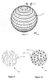
- said superstructure has a spherulite morphology, wherein helices of chiral nematic, liquid crystal are arranged in a lamellar-like structure, and said lamellar-like structure of helices has curvature (i.e. it is not planar) and forms a generally concentric, equidistant-curve pattern within a generally spherical body.
- said spherulite morphology has axes of chiral nematic, liquid crystal helices aligned perpendicular to a surface of a polymer shell's inner wall and arranged generally in a radial direction.
- liquid crystal molecules align to the inside wall of a shell with parallel (synonymous with planar) alignment.
- the index of refraction is generally spherically symmetrical and varies continuously along a radial.
- the spherulite morphology of the light scattering/absorbing state has just one disclination line (synonymous with defect line), and the disclination line is a radial or a diametrical line, the former corresponding to defect points along the line of strength 2, while the latter corresponds to defect points of strength 1.
- the spherulite morphology of the light scattering/absorbing state in a generally spherical body approximates a single domain and is ordered.
- the prior art's light scattering, polydomain state has multiple disclinations arising from its multiple domains.
- the light scattering/absorbing state's spherulite morphology is a superstructure of the helical structures of chiral nematic, liquid crystal, and the superstructure arranges the helices in a lamellar-like structure.
- the lamellar-like structure comprises a first lamella having a minimum refractive index corresponding to a liquid crystal's ordinary refractive index and an average refractive index taken over adjacent liquid crystal director regions, and a second lamella having a maximum refractive index corresponding to a liquid crystal's extraordinary index and an average refractive index taken over adjacent liquid crystal director regions.
- the period of the laminar-like structure is half the pitch of the helical structure of a chiral nematic, liquid crystal.
- a chiral nematic, liquid crystal body inside a generally spherical polymer shell that enforces a spherulite morphology on the superstructure of the liquid crystal body.
- Strong scattering of incident light in a chiral nematic, liquid crystal body in the light scattering state is created by:
- chiral dopant can be a single compound, or a mixture. Preferably more than one chiral dopant is used. Preferably at least one chiral dopant has a Helical Twisting Power (HTP) magnitude > 20, more preferably > 30. Preferably another chiral dopant has an HTP of ⁇ 20.
- HTP Helical Twisting Power
- the helical pitch length lower limit determined at least in part by the chiral dopant is preferably > 1 micron, and more preferably > 1.5 microns, and the helical pitch length upper limit is ⁇ 0.5 times the diameter of a liquid crystal body, more preferably ⁇ 0.333 times the diameter, and most preferably ⁇ 0.2 times the diameter.
- the helical-pitch-length's lower limit is preferably > (0.74 microns / extraordinary refractive index of the liquid crystal) and is about half or less the corresponding pitch for light scattering embodiments.
- Incident light rays on a liquid crystal body that are not directed along a radial, follow a spatially curved path through the spherulite morphology that is the summation of interactions with liquid crystal helices that are themselves spatially curved.
- the present invention provides for intermediate states where the applied electrical field/voltage to an electro-optical layer is intermediate a zero applied field (corresponding to the light scattering/absorbing state) and a maximum applied field (corresponding to the transparent state).
- a microencapsulated chiral nematic, liquid crystal body is free of polymer network, or polymer fractions, or solubilized additives that could induce a polydomain / focal conic texture (as is known from the prior art and discussed earlier).
- the discrete bodies of chiral nematic, liquid crystal are microencapsulated by polymer shells having a densely-crosslinked, polymer-network structure.
- Embodiments favoring low angular haze comprise a monolayer of spherical liquid crystal bodies, and preferably the diameters of liquid crystal bodies fall within a narrow range up to the thickness of the electro-optical layer.
- the present invention relates to chiral nematic, liquid crystal devices, also known as cholesteric liquid crystal devices.
- the invention also relates to dichroic dye (synonymous with pleochroic dye) doped chiral nematic, liquid crystal devices, also known as phase change, guest-host (PCGH) devices.
- dichroic dye is solubilized in chiral nematic, liquid crystal thereby converting its light scattering state into a light absorbing state.
- the transparent state minimizes any increase in haze with increasing viewing angle to a display's normal by minimizing the interface area between discrete liquid crystal bodies and the surrounding polymer matrix phase (i.e. the source of such haze).
- the interface area is minimized by:
- a spherical liquid crystal body optimizes the light scattering/absorbing state of the present invention as discussed in following sections.
- the optimum embodiment to minimize haze in the transparent state comprises a monolayer of spherical liquid crystal bodies, and preferably the diameters of liquid crystal bodies fall within a narrow range up to the thickness of the electro-optical layer, see chiral nematic, liquid crystal film 50 in figure 13 .
- the prior art favors an irregular geometric form (e.g., polygonal) for liquid crystal bodies in the light scattering, polydomain state as this optimizes the stabilization of multiple domains. It also requires liquid crystal bodies to be stacked as the thickness of the electro-optical layer is a multiple of the length of a major axis of a liquid crystal body.
- the light scattering/absorbing state is an ordered, liquid crystal texture, and because it is ordered it is readily stable over time and insensitive to size/volume. It replaces the limiting polydomain / focal conic texture of prior art cholesteric, liquid crystal devices, and does not compromise the transparent state. Its light scattering efficiency is equivalent to, or exceeds, that available from the prior art devices having a light scattering, polydomain / focal conic texture.
- a cholesteric, liquid crystal device of the present invention comprises discrete bodies (synonymous with volumes) of chiral nematic, liquid crystal, or dichroic-dye doped, chiral nematic, liquid crystal, arranged in an electro-optical layer, said bodies of liquid crystal are selectively operable in at least two states, namely, a first state that transmits light through a liquid crystal body and a second state that scatters or absorbs light in a liquid crystal body, said discrete bodies are microencapsulated by a polymer shell (synonymous with capsule) and are spheroidal, preferably spherical, said light scattering/absorbing state has an ordered liquid crystal texture that minimizes disclinations or domains within a liquid crystal body, and said light scattering/absorbing state's liquid crystal texture is a superstructure comprising helices of chiral nematic, liquid crystal arranged with a spherulite morphology.
- helices of chiral nematic, liquid crystal are arranged in a lamellar-like structure, and said lamellar-like structure of helices has curvature (i.e. it is not planar) and forms a generally concentric, equidistant-curve pattern within a generally spherical body.
- a liquid crystal body has either a predominantly light scattering state or a predominantly light absorbing state.
- a liquid crystal body In the predominantly light scattering state a liquid crystal body has little or no added dichroic dye while in a predominantly light absorbing state a liquid crystal body has significant dichroic dye solubilized (i.e. doped) in its chiral nematic, liquid crystal.
- the texture of the light scattering/absorbing state in a generally spherical liquid crystal body is sufficiently ordered that any disclinations or domains present within a liquid crystal body have a negligible bearing on (i.e. are not significant to) the optical properties of the state.
- the liquid crystal texture of the light scattering/absorbing state has just one disclination line (synonymous with defect line), and this arises because, as is known, it is not possible to order liquid crystal molecules within a spherical body without creating one or more defects in the director field.
- the disclination line in a liquid crystal body is a radial or a diametrical line, the former corresponds to defect points along the line of strength 2 while the latter corresponds to defect points of strength 1 (see section " Defects in Liquid Crystal” in “Liquid Crystals Nature's Delicate Phase Of Matter” by PeterJ. Collins for general background information).
- the liquid crystal texture of the light scattering/absorbing state in a generally spherical body approximates a single domain and is ordered.
- polydomain state has multiple disclinations arising from its multiple domains; the disclinations are at the interfaces between neighboring domains, and light is heavily scattered at such disclinations or interfaces due to the disorder between (or divergent alignment of) neighboring domains causing a refractive index difference between neighboring domains (see PCT/EP2008/005151 for more information on the light scattering of the polydomain state in the prior art).
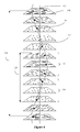
- the light scattering/absorbing state's liquid crystal texture has a superstructure in that it has a structure built on the helical structure of chiral nematic, liquid crystal (a helix 132 in figure 4 describes the twisting of the liquid crystal director 131 and molecules 130), and the superstructure arranges the helices in a lamellar-like structure.
- the lamellar-like structure when viewed perpendicular to the helical axis (see 137 in figure 4 ), can be thought of as comprising (or simplified to comprise) two lamellae, each having a different refractive index and thickness: a first lamella (see 134 in figure 4 ) has a minimum refractive index corresponding to a liquid crystal's ordinary refractive index and is averaged over adjacent liquid crystal director regions as indicated in figure 4 , and a second lamella (see 133 in figure 4 ) has a maximum refractive index corresponding to a liquid crystal's extraordinary index and is also averaged over adjacent liquid crystal director regions.
- lamella 134 is thicker than lamella 133.
- the period of the laminar-like structure (135 in figure 4 ) is half the pitch of the helical structure (136 in figure 4 ) of chiral nematic, liquid crystal.
- the lamellar-like structure of helical axes is visible between crossed polarizers under a microscope (e.g., at a magnification of 1,000 times).
- the lamellar-like structure of chiral nematic, liquid crystal is demonstrated by the so-called fingerprint texture apparent between crossed polarizers when the helical axis is aligned parallel to a substrate (or perpendicular to the viewing direction).
- the helical axis alignment is the opposite of the fingerprint texture observed in the prior art - preferably the helical axis is aligned perpendicular to a shell's surface as shown in figures 5 and 8 .
- the lamellar-like structure within a superstructure twists so that it has curvature. Twisting is periodic, and when a superstructure is viewed between crossed polarizers under a microscope it appears as:
- the separation distance between curves (or the radial displacement of a turn, or the period) of the pattern is shown as dimension 126 in figures 1 to 3 and is about half the pitch of the helical structure of a chiral nematic, liquid crystal.
- the equidistant-curve pattern is concentric in that a projection of the curve pattern onto a flat surface would show curves progressing successively inside each other and having a common center or axis.
- extinctions i.e. black areas
- Two types of extinctions can be seen:
- it is the microencapsulation of a chiral nematic, liquid crystal body inside a generally spherical polymer shell that enforces a spherulite morphology (see liquid crystal body 105 in figure 5 ) on the superstructure of a liquid crystal body.
- liquid crystal molecules align to the inside wall of a shell with either parallel (synonymous with planar) or perpendicular (synonymous with homeotropic) alignment, and preferably with parallel alignment, and so alignment of liquid crystal molecules grows from the outside inward enforcing a generally spherical alignment of liquid crystal molecules (the exception being defect points arising from the packing of a 'layer' of liquid crystal molecules on a spherical surface as discussed earlier).
- a discrete liquid crystal body has generally planar interface surfaces arising from a generally polygonal shape in a polymer matrix, and these planar faces influence adjacent liquid crystal molecules to align to the polymer interface surface enforcing a planar alignment of liquid crystal molecules in that region of a liquid crystal body, and when planar aligned liquid crystal molecules originating from one planar interface surface impinge on those originating from another planar interface surface at a different angle, a disclination occurs along the interface between the two as discussed earlier for the polydomain state.
- planar aligned liquid crystal molecules originating from one planar interface surface impinge on those originating from another planar interface surface at a different angle
- the generally concentric, equidistant-curve pattern of the lamellar-like structure within a generally spherical body is analogous to the "ringing" or “banding" observed with some polymer spherulites and said to arise (in polymer spherulites) from the helical twisting of lamellae in a radial direction.
- a liquid crystal body has a spherulite morphology in which its lamellar-like structure twists in a helical manner in a radial direction.
- the analogy with polymer spherulites extends to negative spherulites and positive spherulites.
- Negative polymer spherulites have the lowest refractive index in a radial direction and are analogous to the helical axis being aligned in a radial direction in a chiral nematic, liquid crystal body (as shown in figure 5 )
- positive polymer spherulites have the highest refractive index in a radial direction and are analogous to the helical axis being aligned perpendicular to a radial direction in a chiral nematic, liquid crystal body.
- a negative, spherulite morphology for a liquid crystal body in the light scattering/absorbing state is preferred.
- the analogy between the spherulite morphology of liquid crystal bodies of the present invention and the spherulite morphology of polymers crystallized from melt or concentrated solutions do not extend to the growth of a spherulite morphology.
- the spherulite morphology grows from the outside in taking on an alignment to the spherical inner wall of a microencapsulating shell, whereas in a polymer spherulite, the spherulite morphology grows from the inside out originating from a seed /nucleation site and merely stops growing when it impinges on a surface (its 'rings' do not align to a surface it impinges on).
- strong scattering of incident light in a chiral nematic, liquid crystal body in the light scattering state is created by:
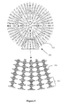
- Figure 5 shows a cross section of a liquid crystal body 105 through its centre and parallel to a viewing face in the spherulite morphology of the light scattering state; light falling on a viewing face of a display device with such a liquid crystal body makes an angle to the plane of the page.
- the cross section through the spherulite morphology in figure 5 can be thought of as concentric 'lamellae shells' having an alternating refractive index and an alternating 'shell' thickness, and in this regard would appear as shown in figure 6 .
- Lamella 133 from figure 4 gives the refractive index and thickness of a first 'lamella shell' and lamella 134 from figure 4 gives the refractive index and thickness of a second 'lamella shell'; see figure 6 .
- the thickness of these lamella are on the same scale as the wavelength of visible light and are varied in proportion to the helical pitch (the period 135 of the lamellar-like structure is half the helical pitch 136, see figure 4 ).
- the thickness of a lamella (133 or 134 in figures 4 and 6 ) is preferable ⁇ 0.56 micron (i.e. the centre of the visible range) and more preferably ⁇ 0.74 micron (i.e. outside the visible range).
- the helical pitch is preferably > 1 micron, and more preferably > 1.5 microns.
- Light scattering in the concentric 'lamellae shells' of the spherulite morphology is complex. It comprises light reflection and light transmission (with refracted angle) at the quasi interface between 'lamellae shells', and also light diffraction and dispersion. Incident light rays that do not propagate along a radial see 'lamellae shells' for at least part of the distance travelled in a liquid crystal body. This can be visualized by imagining incident light rays that are perpendicular to the plane of the page when looking at figures 5 and 6 .
- Such perpendicular light rays will encounter the refractive index of liquid crystal molecules varying between n o and n e as a helix twists for at least a short distance within a liquid crystal body.
- An incident light ray that makes an angle to the plane of the page can be treated similarly by taking a section through the centre of a liquid crystal body at right angles to the incident ray; in such a section/plane a light ray will again encounter the refractive index of liquid crystal molecules varying between n o and n e .
- incident light rays that propagate along a radial would not encounter 'lamellae shells' and would see a uniform refractive index of about the liquid crystal's extraordinary index. But such radial rays encounter a defect point (see earlier discussion of disclination lines) at a liquid crystal's centre and are scattered.
- Mie scattering also known as the Mie solution to Maxwell's equations
- the Mie solution to Maxwell's equations describes the scattering of light by an amorphous sphere when the dimensions under consideration are similar to the wavelength of light.
- Others have extended Mie scattering to concentric 'amorphous shells' having different refractive indices and such models could be applied to embodiments of the present invention to model light scattering, though the radial, helical-twisting shown in figure 5 adds an optically active dimension to a concentric 'lamella shell' treatment (i.e. a "lamella shell' is optically active).
- a phenomenon thought to be a contributor to the light scattering efficiency of chiral nematic, liquid crystal bodies of the present invention is 'total internal reflection'.
- a light ray 138 incident at an angle to the plane of the page, undergoes 'total internal reflection' in a high refractive index concentric 'lamella shell' for a short distance within a liquid crystal body until the curvature (or birefringence variation) causes the light ray to be transmitted into an outer, lower index 'lamella shell' (i.e. as the critical angle for incident light is no longer exceeded). Reflection and transmission (with refraction angle) of light ray 138 by other lamelle in figure 6 is not shown.
- a liquid crystal body has multiple such concentric 'lamellae shells' thereby making the 'total internal reflection' phenomenon just described more significant.
- the pitch is ⁇ 0.5 times the diameter of a liquid crystal body, more preferably ⁇ 0.333 times the diameter, and most preferably ⁇ 0.2 times the diameter.
- chiral dopant(s) can be a single compound, or a mixture.
- Preferably more than one chiral dopant is used; preferably at least one chiral dopant has a Helical Twisting Power (HTP) magnitude > 20, more preferably > 30; and preferably another chiral dopant has an HTP of ⁇ 20.
- Chiral dopant, nematic liquid crystal and dichroic dye compounds are available from numerous liquid crystal suppliers including Merck GmbH and Chisso Corporation (JP).
- the explanation offered for the strong light scattering of the spherulite morphology of the present invention has been a simplified one based on a lamellar-like structure having an abrupt/step change in refractive index from one lamella to the next.
- the lamella-like structure offers an explanation for the upper and lower limits for the helical pitch length given earlier and proven in trials by the applicant to maximize light scattering in the spherulite morphology of the light scattering state.
- Further support for a lamellar-like structure is the concentric, extinction curves visible between crossed polarizers under a microscope when viewing the spherulite morphology of the light scattering state.
- An alternative explanation of the strong light scattering in the spherulite morphology of the present invention is that an incident light ray on a chiral nematic liquid crystal helix is transmitted with a refraction angle if the ray makes an angle to the helical axis, and as neighboring helices are spatially curved the transmitted light ray follows a curved path (see incident light ray 142 in figure 6 ).
- the curved paths followed by rays on exiting a liquid crystal body vary spatially significantly and cause the strong light scattering in the spherulite morphology.
- a liquid crystal body is spherical and its index of refraction is generally spherically symmetrical (see figure 5 for example) and varies continuously along a radial when the axes of the chiral nematic, liquid crystal's helices are aligned along radials.
- the light absorbing state of the present invention is similar to the light scattering state just described. The differences are the doping of the chiral nematic, liquid crystal with dichroic dye, and using a helical pitch length that is significantly shorter than the corresponding light scattering state.
- several dichroic dyes can be solubilized in the liquid crystal phase to achieve a specific color, or to achieve black. The latter is particularly attractive for window applications as, at a minimum, no light is transmitted.
- the dichroic dye within a liquid crystal body adsorbs visible light (e.g., sunlight).
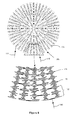
- Figure 7 is similar to figure 4 except it also shows dichroic dye molecules 139 (the lamellae 143 and 144 are equivalent to figure 4 's 133 and 134, and the lamellar-like structure period 145 is equivalent to 135).
- the dichroic dye molecules 139 are anisotropic and generally align with the liquid crystal director 131 as it twists to describe a helix 132.
- the light absorbing state of the present invention is opaque, assuming adequate electro-optical layer thickness, because light absorbing by dichroic dye molecules combines favorably with light scattering by chiral nematic, liquid crystal molecules in the spherulite morphology.
- light absorption is a maximum when the propagating direction of an incident light ray is along a chiral nematic, liquid crystal's helical axis (parallel to axis 137 in figure 7 ).
- Incident light is absorbed in all directions of its electric field as a ray travels one quarter of a helix (corresponds to orthogonal orientations of the long axis of a dye molecule). It will be appreciated that as the angle between a helix's axis and an incident light ray increases the absorbing efficiency of the dye molecules reduces.
- Light absorption is a minimum when the propagating direction of an incident light ray is perpendicular to a chiral nematic, liquid crystal's helical axis (perpendicular to axis 137 in figure 7 ). In this case the electric field resolved along a dye molecule's long axis is absorbed while the electric field resolved along an orthogonal axis is not (i.e. linearly polarized light is transmitted).
- a cross section of a dichroic dye doped, liquid crystal body through its centre and perpendicular (i.e. a different perspective to figure 5 ) to a viewing face in the light absorbing state shows dichroic dye molecules 139 in the spherulite morphology.
- Light falling on a viewing face of a display device with such a liquid crystal body is in the plane of the page of figure 8 .
- An incident light ray 140 that is generally directed towards a liquid crystal body's center will travel generally along a radially arranged helical axis and so will be strongly absorbed by dye molecules.
- a minimum helical pitch in light absorbing embodiments is preferably sufficiently long that the light absorbing state is free of Bragg reflection of visible light and Bragg reflects, if any, in the infra-red region.
- the pitch length in light absorbing embodiments is > (0.74 microns / extraordinary refractive index of the liquid crystal).
- the pitch is > (0.74 microns /1.7) or 0.435 microns.
- the helical pitch is preferably about half or less the corresponding pitch for light scattering embodiments.
- liquid crystal molecules align parallel or perpendicular to an applied electrical field depending on whether the dielectric anisotropy of the liquid crystal is > 0 or ⁇ 0.
- the chiral nematic, liquid crystal has a positive dielectric anisotropy.
- Figure 9 shows a cross section of a chiral nematic, liquid crystal body 105 (dielectric anisotropy > 0) through its centre and perpendicular to a viewing face in the transparent state (the electrical signal and the electrodes are not shown)
- the helical structure of chiral nematic, liquid crystal completely unwinds and the spherulite morphology of the light scattering state disappears.
- a liquid crystal body is encapsulated with a polymer wall whose refractive index matches (preferably to within 0.01, and more preferably to within 0.002) the liquid crystal's ordinary refractive index, and in turn matches the surrounding polymer matrix in an electro-optical layer.
- Figure 10 shows a cross section of a dichroic dye doped, chiral nematic, liquid crystal body 108 through its centre and perpendicular to a viewing face in the transparent state It is similar to figure 9 with the exception that the added dichroic dye molecules 139 align with the liquid crystal molecules 130 and parallel to the applied electrical field.
- dichroic dye in liquid crystal bodies is effective in further reducing a viewer's perception of haze in the transparent state for viewing angles to the face of a display/ smart window from 10 to 90 degrees.
- the present invention also provides for intermediate states where the applied electrical field/voltage to an electro-optical layer is intermediate a zero applied field (corresponding to the light scattering/absorbing state as previously described) and a maximum applied field (corresponding to the transparent state as previously described).
- a zero applied field corresponding to the light scattering/absorbing state as previously described
- a maximum applied field corresponding to the transparent state as previously described.
- the helical pitch increases causing the number of concentric 'lamellae shells' to reduce and the scattering/absorbing efficiency to reduce.
- a liquid crystal body can have an outer region generally aligned parallel to the electrical field and a core region that still has helical structures.
- the spherulite morphology may reduce in volume to a core within a liquid crystal body as the transparent state approaches.
- the discrete bodies of chiral nematic, liquid crystal are microencapsulated inside polymer shells (synonymous with capsules), the reason is that in general microencapsulation processes create shells having a spherical cavity for the microencapsulated electro-optical fluid.
- the techniques of microencapsulation were discussed earlier in the background.
- shells are not mechanically robust and their shape distorts in the subsequent process steps necessary to form an electro-optical layer of shells.
- the distorting of the shape of shells to be more polygonal than spherical in an electro-optical layer is generally desirable in the prior art.
- a microencapsulated chiral nematic, liquid crystal body is free of polymer network, or polymer fractions, or solubilized additives that could induce a polydomain / focal conic texture (as is known from the prior art and discussed earlier).
- Figure 11 is a cross sectional view showing an embodiment of a chiral nematic, liquid crystal display device 115 having an electro-optical layer 24 of shells 113 (comprising spherical liquid crystal bodies 105 microencapsulated by polymer wall 17) dispersed in a polymer matrix 19 (synonymous with binder). Dichroic-dye-doped, chiral nematic liquid crystal embodiments are similar.
- Shells 113 can be dispersed as a monolayer, 24b, or a stacked layer, 24a.
- Electrodes 11a and 11b are made from indium tin oxide (ITO) or other suitable optically-clear, conductive material.
- ITO indium tin oxide
- One or both electrodes can be patterned to create a segmented display device or a matrix of pixels (i.e., picture elements), or alternatively, neither electrode is patterned in switchable film applications an example of which is shown in figure 13 .
- one or both substrates 10a and 10b are a transparent, flexible plastic film such as polyethylene terephthalate (PET) or polycarbonate (PC), however substrates 10a and 10b can also be a rigid material such as glass.
- electrodes 11a and 11b need not be in direct contact with the electro-optical layer 24, but can be coupled to the layer through for example, a dielectric layer (not shown). It is sufficient that an electrical field between the electrodes provides the necessary field strength to control an electro-optical layer.
- one of the substrates may be glass and the active matrix transistors and pixel electrodes would be formed on the glass (thought the active matrix transistors and pixel electrodes may also be formed on a plastic film).
- electrode 11a (the continuous electrode) is overlaid with a black mask or matrix (not shown in the figures but typically an organic material with carbon black particles) that hides the dead region between the electrodes of pixels, as will be familiar from the prior art.
- Figure 12 is a cross sectional view of an embodiment of a color display device 116 having a color patterned, electro-optical layer comprising dichroic-dye-doped, chiral nematic, liquid crystal bodies 108.
- a color display device 116 having a color patterned, electro-optical layer comprising dichroic-dye-doped, chiral nematic, liquid crystal bodies 108.
- Advantageously such an embodiment eliminates the separate color filter of prior art color devices and is described in greater detail in co-pending PCT application entitled "A Method For Microencapsulating Electro-Optical Fluid" (Attorney Ref: P103105PC00).
- the electro-optical layer is divided into discrete regions corresponding to color subpixels (6, 7, and 8), and optical adhesive 15 fills inter-regions in the electro-optical layer.
- Subpixel regions cooperate to form a pixel 9, for example, a red region (12), a green region (13) and a blue region (14).
- the color in a subpixel comes from the dichroid dyes solubilized in the region's chiral nematic, liquid crystal shells, hence a blue subpixel has shells incorporating blue-color-creating dichroic dye(s) whereas a red subpixel has different shells (those incorporating red dye(s)).
- Blue region 14 is shown in greater detail as 14a and 14b.
- the shells may be stacked, 14a, or be a monolayer, 14b.
- Display device 116 requires three different color inks, one for each type of dichroic-dye-doped, chiral nematic, liquid crystal shell, and a method to screen-print the inks to form the color display device shown in figure 12 is described in co-pending PCT application entitled "A Method For Microencapsulating Electro-Optical Fluid" (Attorney Ref: P103105PC00).
- Figure 13 shows an embodiment of a smart window 40 comprising chiral nematic, liquid crystal film 50 laminated between glass panes 41a and 41b.
- Film 50 is similar to device 115 in figure 11 .
- the electro-optical layer shown is a monolayer of shells 113, the liquid crystal bodies 105 are spherical and their diameters fall within a narrow range up to the thickness of the electro-optical layer.
- connection ledges are prepared: copper or other highly conductive flexible material, 43a and 43b, is bonded to ITO electrodes 11a and 11b via conductive adhesive and / or conductive ink 44a and 44b; the window edge area is sealed with a silicone sealant 46a and 46b; polarized driving signals can be applied to the liquid crystal film 50 via bonded / soldered cables 45a and 45b respectively.
- the liquid crystal film 50 is laminated on both sides to glass panes 41a and 41b via interlayers 42a and 42b respectively.
- An interlayer can be polyvinyl butyral PVB, ethylene-vinyl acetate EVA or polyurethane PU, and advantageously incorporates a UV blocking function.
- EVA interlayer is used as these have the lowest maximum processing temperature.
- a vacuum-bag glass laminating process is preferred over an autoclave. Suitable interlayer include EVASAFE from Bridgestone Corporation, Japan, and SLEC from Sekisui, Japan. Process guidelines for laminating PET films to glass are available from both suppliers.
- Figure 14 shows an embodiment of a chiral nematic, reflective display device 114 in a black/dark state and is described in co-pending US application entitled "Reflective Display Device” (Attorney Ref: P103447US00).
- Dichroic dye is not used; instead a black layer 104 on the rear electrode 11b absorbs light that is transmitted by a liquid crystal body 105 when a sufficiently large voltage 110 is applied across the electro-optical layer 111.
- the electro-optical layer 111 in figure 14 scatters light by reflection, refraction and diffraction and this light is characterized by two components:
- incident light ray bundle 87 is focused by the front semi-sphere of a shell 113 because a shell is generally surrounded by air 62 within the electro-optical layer 111.
- the exploded view in figure 14 shows ray bundle 87 being transmitted by a liquid crystal body 105 inside a shell 113 in to the shell's wall 17, and then, due to an optical interface made by a polymer matrix fraction 61, the ray bundle 87 is absorbed by a black layer 104 with negligible reflection.
- total internal reflection at a polymer/air interface is suppressed for the circular portion of a shell's rear semi-sphere in optical contact with a black, absorbing layer 104.
- Example 1 microencapsulating chiral nematic, liquid crystal
- a stable, chiral nematic liquid crystal emulsion in deionised water was prepared using a limited coalescence method.
- a blade stirrer held the emulsion under constant stirring at 100 rpm.
- the deionised water phase was 190 ml.
- the stable liquid crystal emulsion was measured using a Horiba LA920 (Japan).
- the liquid crystal droplet mean was 8.5 microns, the standard deviation (SD) was 1.15 microns and the coefficient of variation (SD/mean x 100) was 13.5%.
- Example 2 (forming a second layer on shells)
- the second half of the liquid crystal emulsion from example 1 was used to repeat the microencapsulation described in example 1 ahead of forming a second layer on shells as will be described now.
- Example 3 (preparing a solvent-free, chiral nematic, liquid crystal ink)
- the ink's hydrophobic solution was made up using 0.281 g of trimethylolpropane trimethacrylate, 1.823g of 2-phenylethyl acrylate, 1.742g of tert-butyl methacrylate, and 0.154g of photoinitiator Irgacure IRG651, all were sourced from Sigma-Aldrich.
- the solution was heated to 60 degrees Celsius, sonified to ensure all components were solubilized, and then cooled to room temperature (20 degrees Celsius).
- the electro-optical ink Sonified the electro-optical ink at low power to disperse the shells in the continuous phase and achieve a uniform, paste-like consistency.
- the resulting electro-optical ink comprises chiral nematic, liquid crystal inside hydrophobic polymer shells and dispersed in a hydrophobic monomer solution.
- the ink can be cured by ultra-violet light and is solvent-free.
- Example 4 (preparing a chiral nematic, liquid crystal, display device)
- Example 5 microencapsulating dichroic-dye-doped, chiral nematic, liquid crystal
- dichroic-dye-doped, nematic liquid crystal ZLI4714/3 from Merck (Japan) was used (as supplied) instead of example 1's nematic liquid crystal (MLC2058).
- the ratio of chiral dopant to the nematic liquid crystal was increased with respect to example 1.
- the liquid crystal phase in the emulsion had 9.08g of ZLI4714/3, 0.3125g of ZLI4571 and 0.604g of S811.
- Example 6 (preparing a dichroic-dye-doped, chiral nematic, liquid crystal, display device) Prepared a dichroic-dye-doped, chiral nematic, liquid crystal ink using the shell powder from example 5 and following the description in example 3. Screen-printed the ink onto ITO coated PET film. Viewing the wet print under the microscope confirmed that shells remained spherical and free of apparent defects. When viewed between cross polarizers the spiral-helix, curve pattern of the spherulite morphology was apparent thought the spacing between curves was significantly reduced with respect to that observed for example 4. When viewing shells it is necessary to increase the microscope's light intensity to overcome light absorption by the dichroic dye, and increase magnification to overcome the fine spacing between curves (with respect to example 4).
Abstract
Description
- The present invention relates to: co-pending PCT application entitled "A Method For Microencapsulating Electro-Optical Fluid" (Attorney Ref: P103105PC00); claiming priority from Irish Application Nos.
S2012/0033 S2012/0034 S2012/0035 - The present invention relates to a method for operating a chiral nematic, liquid crystal display device.
- The invention has particular application in areas such as: light control films for use in glazing applications that are capable of switching between transparent and translucent states, or between transparent and light blocking (synonymous with dark or opaque) states, generally known as "switchable windows" or "smart windows" or "dimmable windows"; and see-through displays that comprise a matrix of pixels each capable of being selectively operated in a transparent state and a translucent or dark state, for use in applications like shop front windows, or the window of a bus or train, without blocking visual access through the window. Other applications include reflective display applications, particularly sunlight readable displays.
- In a flexible, chiral nematic (synonymous with cholesteric) liquid crystal display, the liquid crystal is dispersed in a polymer matrix and sandwiched between plastic sheets. The prior art provides three types of technical approach to dispersing the liquid crystal in a polymer matrix: the first are devices generally described as 'polymer dispersed', the second are devices having replicated polymer structures, and the third are devices that microencapsulate (synonymous with encapsulate) the liquid crystal. All three provide containment for the liquid crystal fluid so that instead of the substrates sandwiching a continuous fluid phase, the substrates sandwich discrete bodies (volumes) of fluid (i.e. the fluid phase is disconthuous) surrounded by a transparent, continuous polymer matrix that spans between the substrates to provide a solid, liquid crystal film.
- A problem arises when liquid crystal is dispersed as a discontinuous phase in a continuous polymer matrix because liquid crystal is birefringent. In the transparent state (synonymous with field ON state) a see-through, display device for use in window/glazing applications must be transparent to specular light over a wide range of viewing angles. In particular its inherent haze must remain acceptably low as viewing angle increases. Yet, as is known with prior art polymer dispersed, liquid crystal devices, haze increases with viewing angle due to the increasing refractive index mismatch between the polymer matrix and the birefringent liquid crystal; assuming that the polymer matrix is matched to the ordinary refractive index of the liquid crystal then as the viewing angle to the display normal increases the resulting refractive index for the liquid crystal in the transparent state comprises an increasing fraction of the extraordinary refractive index, and so mismatch and consequently haze increases with increasing viewing angle.
- The requirement for clear, haze-free viewing over as extensive a range of viewing angles as possible is extremely important for window applications. A person standing directly in front of a 2M x 2M window will encounter a range of viewing angles depending on the viewer's distance from the window and on which part of the window is being looked through. If the viewer's eye is 2 meters away from the centre of the window, for example, the angle to the corner of the window is about 35 degrees; in other words, for such a window to be transparent at a distance of 2 meters, it requires a haze-free viewing angle of 35 degrees. For the same window to be transparent from a distance of 1 meter, however, increases the required haze-free viewing angle to about 55 degrees.
- In patent application
PCT/EP2008/005151 PCT/EP2008/005151 - In constructing a flexible, liquid crystal film the technical approach to dispersing the liquid crystal in a polymer matrix must be considered. In two of these three approaches- polymer dispersed and replicated structures- the polymer walls that surround the discrete liquid crystal volumes are formed in situ on the polymer substrate and the liquid crystal is coated as a solution onto the substrate. Patent application
PCT/EP2008/005151 - 1) Polymer Dispersed Liquid Crystal (PDLC) and Nematic Curvilinear Aligned Phase (NCAP), both use nematic liquid crystal;
- 2) Polymer Stabilised Cholesteric Texture (PSCT); and
- 3) Polymer Dispersed Cholesteric Liquid Crystal (PDCLC).
- The cited application also discloses a novel polymer induced phase separation method.
- Information on replicated polymer structures is available from one of its proponents Sipix Inc. and their website (www.sipix.com) references articles on the use of the replicated polymer structures approach with nematic liquid crystal.
- Alternatively, with microencapsulation, the liquid crystal is encapsulated by a thin polymer wall in the form of a shell (synonymous with capsule), typically spherical in shape, before being coated onto a substrate. This means that the liquid crystal fluid is in a solid form-discrete, sealed spherical volumes inside a polymer wall or skin- before being coated onto a substrate and used in a device. The known techniques for microencapsulation can be divided into two types:
- a) The hydrophilic shell (synonymous with capsule) type: the bulk polymer in a shell has a dominant hydrophilic nature. Generally the prior art methods require the majority by weight of the polymer wall precursors to be water-soluble and to be solubilized in an aqueous phase at some point during the microencapsulation process.
- b) The hydrophobic shell (synonymous with capsule) type: the bulk polymer in a shell has a dominant hydrophobic nature. Generally the prior art methods require the majority by weight of the polymer wall precursors to be soluble or partly soluble in the liquid crystal fluid to be microencapsulated.
- The former type includes conventional and complex coacervation, and interfacial polymerization processes.
US 6,120,701 discloses a technique for microencapsulating nematic liquid crystal using an interfacial polymerisation process that could be applied to microencapsulate cholesteric liquid crystal. - In the hydrophobic-shell type, a shell's wall is generally formed from hydrophobic monomers having a slight hydrophilic functionality. Ahead of microencapsulating, the monomers are solubilized partly or completely in the hydrophobic, liquid crystal fluid and as polymerization proceeds the polymer phase separates from the liquid crystal and forms at the interface with the aqueous phase and microencapsulates the liquid crystal fluid with a hydrophobic polymer wall. For examples of liquid crystal microencapsulated in this way see Rohm and Haas Company's
US 5,976,405 or PolyDisplay'sUS 7,397,530 . - Once a cholesteric liquid crystal fluid is microencapsulated it can be dispersed in a solution containing polymer matrix (synonymous with binder) precursors to form an electronic ink. This electronic ink can be coated or printed onto a variety of flexible and rigid substrates. The coated/printed ink is then formed into a solid (by curing or film forming techniques) comprising discrete volumes of liquid crystal fluid enclosed inside polymer shells that in turn are dispersed in a polymer matrix and sandwiched between film substrates having transparent electrodes. In smart window applications the resulting cholesteric liquid crystal film is laminated to regular window glass panes on both sides using adhesive sheets known as interlayers.
- Another aspect of the prior art in relation to cholesteric liquid crystal devices is that the light scattering state (generally the field OFF state) is based on forming and stabilizing (over time) a polydomain state, synonymous with focal conic state, in the discrete cholesteric liquid crystal volumes. It is important to note that the polydomain state in cholesteric liquid crystal represents a limiting factor because unless it is stabilized by specific means it is not stable over time and transitions to a weakly, semi transparent state within seconds to minutes of removing an electrical field. For example, in the applicant's
PCT/EP2008/005151 US 5,455,083 the method to stabilize a polydomain state is to add chiral smectic C liquid crystal (i.e. a different liquid crystal phase) to cholesteric liquid crystal. InUS5,437,811 andUS 6,203,723 B1 polymer network is used to stabilize a polydomain/focal conic state by forming fibrous network within the liquid crystal phase (know as polymer stabilized cholesteric texture (PSCT) devices) to physically disrupt domains. InUS 6,767,480 novel materials are dispersed within the cholesteric liquid crystal to stabilize the polydomain state. While the light scattering, polydomain / focal conic state of prior art devices can be stable over time, the technical approaches used impose undesirable limitations on the discrete volume that can be stabilized, or introduce undesirable elements such as polymer network or additives into a discrete liquid crystal volume that can compromise the transparent state (i.e. the field ON state). Hence, there is a need for a light scattering state (i.e. the field OFF state) that is stable over time, that allows the mean diameter of discrete liquid crystal volumes (i.e. bodies) to be up to the thickness of a display's electro-optical layer, and that does not introduce elements that compromise the transparent state. - In general, the meaning given to liquid crystal terms is consistent with the prior art:
- A liquid crystal molecule aligns to a surface, for example to a polymer interface, or to an electrical field.
- A liquid crystal director is the preferred local orientation (i.e. alignment) of liquid crystal molecules, and individual molecules can be at different angles to the director.
- The order parameter S is a way of averaging the angle a large number of liquid crystal molecules makes with the director. S = 1 if all molecules are exactly parallel with the director.
- Cholesteric liquid crystal is synonymous with chiral, nematic liquid crystal.
- Chiral nematic liquid crystal exhibits a helical structure in that the liquid crystal director is uniformly rotated or twisted perpendicular to the axis of a helix. The pitch is the distance for one full liquid crystal director rotation. The helical structure is spontaneous (i.e. it is a low energy state).
- A disclination represents an extremely small region at the interface between (or within) otherwise well defined director regions where the director changes abruptly and is really undefined as it points in many directions. A disclination therefore represents a defect and can be a point or line defect. Different types of disclination are possible and to classify a disclination a number is assigned to it based on the strength of the defect.
- A domain in cholesteric liquid crystal is defined as a region or volume that is free of disclinations or defects.
- Light scattered or transmitted by a liquid crystal body is synonymous with visible light scattered or transmitted.
- Liquid crystal texture is synonymous with morphology.
- In summary, a method to minimize haze in the transparent state (according to the applicant's
PCT/EP2008/005151 - The present invention provides a cholesteric, liquid crystal device comprising a plurality of discrete spheroidal bodies of chiral nematic, liquid crystal, microencapsulated by a polymer shell and arranged in an electro-optical layer sandwiched between electrodes, said bodies of liquid crystal being selectively operable in at least two states, a first state that transmits light through a liquid crystal body and a second state that scatters or absorbs light in a liquid crystal body, each body in said second state having an ordered liquid crystal texture that minimizes disclinations or domains within the liquid crystal body, said liquid crystal texture comprising a superstructure of helices of chiral nematic, liquid crystal.
- In light absorbing embodiments of the present invention, the liquid crystal comprises dichroic-dye doped, chiral nematic, liquid crystal.
- Preferably, said microencapsulated bodies are spherical.
- In embodiments of the present invention, said superstructure has a spherulite morphology, wherein helices of chiral nematic, liquid crystal are arranged in a lamellar-like structure, and said lamellar-like structure of helices has curvature (i.e. it is not planar) and forms a generally concentric, equidistant-curve pattern within a generally spherical body.
- In embodiments, said spherulite morphology has axes of chiral nematic, liquid crystal helices aligned perpendicular to a surface of a polymer shell's inner wall and arranged generally in a radial direction.
- In embodiments, liquid crystal molecules align to the inside wall ofa shell with parallel (synonymous with planar) alignment. In said superstructure having a spherulite morphology, the index of refraction is generally spherically symmetrical and varies continuously along a radial.
- In embodiments, the spherulite morphology of the light scattering/absorbing state has just one disclination line (synonymous with defect line), and the disclination line is a radial or a diametrical line, the former corresponding to defect points along the line of strength 2, while the latter corresponds to defect points of strength 1.
- Accepting this one disclination line, the spherulite morphology of the light scattering/absorbing state in a generally spherical body approximates a single domain and is ordered. By contrast, the prior art's light scattering, polydomain state has multiple disclinations arising from its multiple domains.
- The light scattering/absorbing state's spherulite morphology is a superstructure of the helical structures of chiral nematic, liquid crystal, and the superstructure arranges the helices in a lamellar-like structure. The lamellar-like structure comprises a first lamella having a minimum refractive index corresponding to a liquid crystal's ordinary refractive index and an average refractive index taken over adjacent liquid crystal director regions, and a second lamella having a maximum refractive index corresponding to a liquid crystal's extraordinary index and an average refractive index taken over adjacent liquid crystal director regions. The period of the laminar-like structure is half the pitch of the helical structure of a chiral nematic, liquid crystal.
- In embodiments when the spherulite morphology of the light scattering/absorbing state is viewed between crossed polarizers under a microscope it appears as:
- a) a spherical helix with equidistant-curve spacing in a generally spherical body,
- b) concentric (i.e. successively placed inside another) spherical helices with equidistant-curve spacing in a generally spherical body, or
- c) concentric circles with equidistant-curve spacing in a generally spherical body,
- In embodiments of the present invention, it is the microencapsulation of a chiral nematic, liquid crystal body inside a generally spherical polymer shell that enforces a spherulite morphology on the superstructure of the liquid crystal body.Strong scattering of incident light in a chiral nematic, liquid crystal body in the light scattering state is created by:
- a) the spherulite morphology, and
- b) using a helical pitch length from a range bounded by an upper and lower limit.
- In light scattering chiral nematic liquid crystal embodiments of the invention, chiral dopant can be a single compound, or a mixture. Preferably more than one chiral dopant is used. Preferably at least one chiral dopant has a Helical Twisting Power (HTP) magnitude > 20, more preferably > 30. Preferably another chiral dopant has an HTP of < 20.
- To maximize light scattering in the light scattering state, the helical pitch length lower limit determined at least in part by the chiral dopant is preferably > 1 micron, and more preferably > 1.5 microns, and the helical pitch length upper limit is ≤ 0.5 times the diameter of a liquid crystal body, more preferably ≤ 0.333 times the diameter, and most preferably ≤ 0.2 times the diameter.
- To maximize light absorbing in the light absorbing state the helical-pitch-length's lower limit is preferably > (0.74 microns / extraordinary refractive index of the liquid crystal) and is about half or less the corresponding pitch for light scattering embodiments.
- Incident light rays on a liquid crystal body that are not directed along a radial, follow a spatially curved path through the spherulite morphology that is the summation of interactions with liquid crystal helices that are themselves spatially curved.
- The present invention provides for intermediate states where the applied electrical field/voltage to an electro-optical layer is intermediate a zero applied field (corresponding to the light scattering/absorbing state) and a maximum applied field (corresponding to the transparent state).
- Preferably in embodiments, a microencapsulated chiral nematic, liquid crystal body is free of polymer network, or polymer fractions, or solubilized additives that could induce a polydomain / focal conic texture (as is known from the prior art and discussed earlier).
- In embodiments the discrete bodies of chiral nematic, liquid crystal are microencapsulated by polymer shells having a densely-crosslinked, polymer-network structure.
- Embodiments favoring low angular haze comprise a monolayer of spherical liquid crystal bodies, and preferably the diameters of liquid crystal bodies fall within a narrow range up to the thickness of the electro-optical layer.
- Embodiments of the invention will now be described, by way of example, with reference to the accompanying drawings, in which:
-
Figure 1 is a rendering of a chiral nematic, liquid crystal body in the light scattering state: it shows the lamellar-like structure of helices twisted in the form of a spherical helix with equidistant-curve spacing in a spherical body as it appears when viewed between crossed polarizers. -
Figure 2 is similar tofigure 1 except it shows two concentric, spherical helices with equidistant-curve spacing in a spherical body. -
Figure 3 is a rendering of the chiral nematic, liquid crystal body in the light scattering state: it shows the lamellar-like structure of helices twisted in the form of concentric circles with equidistant-curve spacing in a spherical body as it appears when viewed between crossed polarizers. -
Figure 4 is a schematic of the helical arrangement of the director in chiral nematic, liquid crystal and how this creates a lamellar-like structure of helices comprising alternating refractive indices. -
Figure 5 shows a cross section of a chiral nematic, liquid crystal body through its centre and parallel to a viewing face in the spherulite morphology of the light scattering state. -
Figure 6 represents the liquid crystal helical structures shown infigure 5 by the corresponding lamellar-like structure. -
Figure 7 is similar tofigure 4 except it also shows dichroic dye molecules generally aligning with the liquid crystal director as it twists in a helix in dichroic dye doped, chiral nematic liquid crystal. -
Figure 8 shows a cross section of a dichroic dye doped, chiral nematic, liquid crystal body through its centre and perpendicular to a viewing face in the spherulite morphobgy of the light absorbing state. -
Figure 9 shows a cross section of a chiral nematic, liquid crystal body through its centre and perpendicular to a viewing face in the transparent state. -
Figure 10 shows a cross section of a dichroic dye doped, chiral nematic, liquid crystal body through its centre and perpendicular to a viewing face in the transparent state. -
Figure 11 is a cross sectional view showing a chiral nematic, liquid crystal display device having an electro-optical layer of spherical shells dispersed in a polymer matrix (synonymous with binder). -
Figure 12 is a cross sectional view of a colour display device having a colour patterned, electro-optical layer comprising dichroic-dye-doped, chiral nematic, liquid crystal. -
Figure 13 is a cross section of a smart window incorporating a switchable film device having an electro-optical layer comprising a monolayer of spherical chiral nematic, liquid crystal bodies. -
Figure 14 is a cross sectional view of a reflective, chiral nematic, liquid crystal, display device in an electrically field aligned state and corresponds with a black optical state. - The present invention relates to chiral nematic, liquid crystal devices, also known as cholesteric liquid crystal devices. The invention also relates to dichroic dye (synonymous with pleochroic dye) doped chiral nematic, liquid crystal devices, also known as phase change, guest-host (PCGH) devices. In embodiments, dichroic dye is solubilized in chiral nematic, liquid crystal thereby converting its light scattering state into a light absorbing state.
- In embodiments of the present invention the transparent state (synonymous with the ON state) minimizes any increase in haze with increasing viewing angle to a display's normal by minimizing the interface area between discrete liquid crystal bodies and the surrounding polymer matrix phase (i.e. the source of such haze). The interface area is minimized by:
- a) allowing the mean volume of discrete, liquid crystal bodies to be maximized, and generally avoiding an upper limit on the mean; and
- b) using generally spherical liquid crystal bodies in the electro-optical layer. Of all the geometric forms having a given volume, the sphere is the one with the smallest surface area and consequently minimizes haze with respect to other geometric forms.
- In relation to point a), it is possible to avoid an upper limit on the mean of liquid crystal bodies because in the present invention neither the light scattering/absorbing state nor the transparent state imposes an upper limit; the mean diameter of discrete, liquid crystal bodies can be up to the thickness of a display's electro-optical layer. In relation to point b, a spherical liquid crystal body optimizes the light scattering/absorbing state of the present invention as discussed in following sections.
- Consequently, the optimum embodiment to minimize haze in the transparent state comprises a monolayer of spherical liquid crystal bodies, and preferably the diameters of liquid crystal bodies fall within a narrow range up to the thickness of the electro-optical layer, see chiral nematic,
liquid crystal film 50 infigure 13 . By contrast, the prior art favors an irregular geometric form (e.g., polygonal) for liquid crystal bodies in the light scattering, polydomain state as this optimizes the stabilization of multiple domains. It also requires liquid crystal bodies to be stacked as the thickness of the electro-optical layer is a multiple of the length of a major axis of a liquid crystal body. - In the present invention the light scattering/absorbing state is an ordered, liquid crystal texture, and because it is ordered it is readily stable over time and insensitive to size/volume. It replaces the limiting polydomain / focal conic texture of prior art cholesteric, liquid crystal devices, and does not compromise the transparent state. Its light scattering efficiency is equivalent to, or exceeds, that available from the prior art devices having a light scattering, polydomain / focal conic texture.
- A cholesteric, liquid crystal device of the present invention comprises discrete bodies (synonymous with volumes) of chiral nematic, liquid crystal, or dichroic-dye doped, chiral nematic, liquid crystal, arranged in an electro-optical layer, said bodies of liquid crystal are selectively operable in at least two states, namely, a first state that transmits light through a liquid crystal body and a second state that scatters or absorbs light in a liquid crystal body, said discrete bodies are microencapsulated by a polymer shell (synonymous with capsule) and are spheroidal, preferably spherical, said light scattering/absorbing state has an ordered liquid crystal texture that minimizes disclinations or domains within a liquid crystal body, and said light scattering/absorbing state's liquid crystal texture is a superstructure comprising helices of chiral nematic, liquid crystal arranged with a spherulite morphology.
- In said superstructure having a spherulite morphology, helices of chiral nematic, liquid crystal are arranged in a lamellar-like structure, and said lamellar-like structure of helices has curvature (i.e. it is not planar) and forms a generally concentric, equidistant-curve pattern within a generally spherical body.
- Preferably in embodiments a liquid crystal body has either a predominantly light scattering state or a predominantly light absorbing state. In the predominantly light scattering state a liquid crystal body has little or no added dichroic dye while in a predominantly light absorbing state a liquid crystal body has significant dichroic dye solubilized (i.e. doped) in its chiral nematic, liquid crystal.
- The texture of the light scattering/absorbing state in a generally spherical liquid crystal body is sufficiently ordered that any disclinations or domains present within a liquid crystal body have a negligible bearing on (i.e. are not significant to) the optical properties of the state. In embodiments the liquid crystal texture of the light scattering/absorbing state has just one disclination line (synonymous with defect line), and this arises because, as is known, it is not possible to order liquid crystal molecules within a spherical body without creating one or more defects in the director field. In embodiments the disclination line in a liquid crystal body is a radial or a diametrical line, the former corresponds to defect points along the line of strength 2 while the latter corresponds to defect points of strength 1 (see section "Defects in Liquid Crystal" in "Liquid Crystals Nature's Delicate Phase Of Matter" by PeterJ. Collins for general background information). Accepting this one disclination line, the liquid crystal texture of the light scattering/absorbing state in a generally spherical body approximates a single domain and is ordered. By contrast, the prior art's light scattering, polydomain state has multiple disclinations arising from its multiple domains; the disclinations are at the interfaces between neighboring domains, and light is heavily scattered at such disclinations or interfaces due to the disorder between (or divergent alignment of) neighboring domains causing a refractive index difference between neighboring domains (see
PCT/EP2008/005151 - In the present invention the light scattering/absorbing state's liquid crystal texture has a superstructure in that it has a structure built on the helical structure of chiral nematic, liquid crystal (a
helix 132 infigure 4 describes the twisting of theliquid crystal director 131 and molecules 130), and the superstructure arranges the helices in a lamellar-like structure. The lamellar-like structure, when viewed perpendicular to the helical axis (see 137 infigure 4 ), can be thought of as comprising (or simplified to comprise) two lamellae, each having a different refractive index and thickness: a first lamella (see 134 infigure 4 ) has a minimum refractive index corresponding to a liquid crystal's ordinary refractive index and is averaged over adjacent liquid crystal director regions as indicated infigure 4 , and a second lamella (see 133 infigure 4 ) has a maximum refractive index corresponding to a liquid crystal's extraordinary index and is also averaged over adjacent liquid crystal director regions. Generallylamella 134 is thicker thanlamella 133. The period of the laminar-like structure (135 infigure 4 ) is half the pitch of the helical structure (136 infigure 4 ) of chiral nematic, liquid crystal. - In embodiments the lamellar-like structure of helical axes is visible between crossed polarizers under a microscope (e.g., at a magnification of 1,000 times). In the prior art the lamellar-like structure of chiral nematic, liquid crystal is demonstrated by the so-called fingerprint texture apparent between crossed polarizers when the helical axis is aligned parallel to a substrate (or perpendicular to the viewing direction). Note, in the present invention the helical axis alignment is the opposite of the fingerprint texture observed in the prior art - preferably the helical axis is aligned perpendicular to a shell's surface as shown in
figures 5 and8 . - In embodiments the lamellar-like structure within a superstructure twists so that it has curvature. Twisting is periodic, and when a superstructure is viewed between crossed polarizers under a microscope it appears as:
- a) a spherical helix with equidistant-curve spacing in a generally spherical body, see
curve 120 ofliquid crystal body 101 infigure 1 ; - b) concentric (i.e. successively placed inside another) spherical helices with equidistant-curve spacing in a generally spherical body, see
figure 2 , two concentric curves, 123 and 124, are shown in liquid crystal body 102; or - c) concentric circles with equidistant-curve spacing in a generally spherical body, see
curve 125 inliquid crystal body 103 infigure 3 . - It will be appreciated that if a liquid crystal body is a spheroid rather than a sphere then these forms will twist with such curvature (i.e. take on the curvature of the microencapsulating shell/capsule). Any defects in the curvature of a shell wall at the interface with the microencapsulated liquid crystal that are of a scale/dimension similar to the helical pitch will result in disturbance of the curve pattern locally. A disclination point or line creates a defect in the curvature, however as mentioned, there is generally just a single disclination line in a spherical liquid crystal body in the present invention's light scattering/absorbing state.
- The separation distance between curves (or the radial displacement of a turn, or the period) of the pattern is shown as
dimension 126 infigures 1 to 3 and is about half the pitch of the helical structure of a chiral nematic, liquid crystal. The equidistant-curve pattern is concentric in that a projection of the curve pattern onto a flat surface would show curves progressing successively inside each other and having a common center or axis. When a superstructure is viewed between crossed polarizers under a microscope, extinctions (i.e. black areas) occur when the liquid crystal director is parallel to either of the axes of the crossed polarizers. Two types of extinctions can be seen: - a) extinctions along the polarization axes of the polarizers due to circular birefringence, if the extinction is a cross-like pattern it is called a Maltese Cross; and
- b) extinctions due to the periodic twisting of the lamellar-like structure.
- In the figures only the second type of extinctions (i.e. due to periodic twisting of the lamellar-like structure) are shown.
- In embodiments of the present invention, it is the microencapsulation of a chiral nematic, liquid crystal body inside a generally spherical polymer shell that enforces a spherulite morphology (see
liquid crystal body 105 infigure 5 ) on the superstructure of a liquid crystal body. This is because liquid crystal molecules align to the inside wall of a shell with either parallel (synonymous with planar) or perpendicular (synonymous with homeotropic) alignment, and preferably with parallel alignment, and so alignment of liquid crystal molecules grows from the outside inward enforcing a generally spherical alignment of liquid crystal molecules (the exception being defect points arising from the packing of a 'layer' of liquid crystal molecules on a spherical surface as discussed earlier). - By contrast, in the prior art a discrete liquid crystal body has generally planar interface surfaces arising from a generally polygonal shape in a polymer matrix, and these planar faces influence adjacent liquid crystal molecules to align to the polymer interface surface enforcing a planar alignment of liquid crystal molecules in that region of a liquid crystal body, and when planar aligned liquid crystal molecules originating from one planar interface surface impinge on those originating from another planar interface surface at a different angle, a disclination occurs along the interface between the two as discussed earlier for the polydomain state. Clearly the conditions necessary to create a stable polydomain / focal conic texture cannot create a spherulite morphology.
- There are some analogies between the spherulite morphology of liquid crystal bodies of the present invention and the spherulite morphology of polymers crystallized from melt or concentrated solutions. In embodiments, the generally concentric, equidistant-curve pattern of the lamellar-like structure within a generally spherical body (when observed between cross polarizers) is analogous to the "ringing" or "banding" observed with some polymer spherulites and said to arise (in polymer spherulites) from the helical twisting of lamellae in a radial direction. In this regard, in embodiments, a liquid crystal body has a spherulite morphology in which its lamellar-like structure twists in a helical manner in a radial direction.
- The analogy with polymer spherulites extends to negative spherulites and positive spherulites. Negative polymer spherulites have the lowest refractive index in a radial direction and are analogous to the helical axis being aligned in a radial direction in a chiral nematic, liquid crystal body (as shown in
figure 5 ), and positive polymer spherulites have the highest refractive index in a radial direction and are analogous to the helical axis being aligned perpendicular to a radial direction in a chiral nematic, liquid crystal body. In embodiments, a negative, spherulite morphology for a liquid crystal body in the light scattering/absorbing state is preferred. - However, the analogy between the spherulite morphology of liquid crystal bodies of the present invention and the spherulite morphology of polymers crystallized from melt or concentrated solutions do not extend to the growth of a spherulite morphology. In the present invention the spherulite morphology grows from the outside in taking on an alignment to the spherical inner wall of a microencapsulating shell, whereas in a polymer spherulite, the spherulite morphology grows from the inside out originating from a seed /nucleation site and merely stops growing when it impinges on a surface (its 'rings' do not align to a surface it impinges on).
- In embodiments of the present invention, strong scattering of incident light in a chiral nematic, liquid crystal body in the light scattering state is created by:
- a) the spherulite morphology, and
- b) using a helical pitch length from a range bounded by an upper and lower limit.
-
Figure 5 shows a cross section of aliquid crystal body 105 through its centre and parallel to a viewing face in the spherulite morphology of the light scattering state; light falling on a viewing face of a display device with such a liquid crystal body makes an angle to the plane of the page. The cross section through the spherulite morphology infigure 5 can be thought of as concentric 'lamellae shells' having an alternating refractive index and an alternating 'shell' thickness, and in this regard would appear as shown infigure 6 .Lamella 133 fromfigure 4 gives the refractive index and thickness of a first 'lamella shell' andlamella 134 fromfigure 4 gives the refractive index and thickness of a second 'lamella shell'; seefigure 6 . In embodiments the thickness of these lamella are on the same scale as the wavelength of visible light and are varied in proportion to the helical pitch (theperiod 135 of the lamellar-like structure is half thehelical pitch 136, seefigure 4 ). To maximize light scattering in the light scattering state the thickness of a lamella (133 or 134 infigures 4 and6 ) is preferable ≥ 0.56 micron (i.e. the centre of the visible range) and more preferably ≥ 0.74 micron (i.e. outside the visible range). Expressed in terms of the helical pitch, to maximize light scattering in the light scattering state the helical pitch is preferably > 1 micron, and more preferably > 1.5 microns. - Light scattering in the concentric 'lamellae shells' of the spherulite morphology is complex. It comprises light reflection and light transmission (with refracted angle) at the quasi interface between 'lamellae shells', and also light diffraction and dispersion. Incident light rays that do not propagate along a radial see 'lamellae shells' for at least part of the distance travelled in a liquid crystal body. This can be visualized by imagining incident light rays that are perpendicular to the plane of the page when looking at
figures 5 and6 . Such perpendicular light rays will encounter the refractive index of liquid crystal molecules varying between no and ne as a helix twists for at least a short distance within a liquid crystal body. An incident light ray that makes an angle to the plane of the page can be treated similarly by taking a section through the centre of a liquid crystal body at right angles to the incident ray; in such a section/plane a light ray will again encounter the refractive index of liquid crystal molecules varying between no and ne. In theory only those incident light rays that propagate along a radial would not encounter 'lamellae shells' and would see a uniform refractive index of about the liquid crystal's extraordinary index. But such radial rays encounter a defect point (see earlier discussion of disclination lines) at a liquid crystal's centre and are scattered. - In the prior art Mie scattering (also known as the Mie solution to Maxwell's equations) describes the scattering of light by an amorphous sphere when the dimensions under consideration are similar to the wavelength of light. Others have extended Mie scattering to concentric 'amorphous shells' having different refractive indices and such models could be applied to embodiments of the present invention to model light scattering, though the radial, helical-twisting shown in
figure 5 adds an optically active dimension to a concentric 'lamella shell' treatment (i.e. a "lamella shell' is optically active). - A phenomenon thought to be a contributor to the light scattering efficiency of chiral nematic, liquid crystal bodies of the present invention is 'total internal reflection'. In
figure 6 alight ray 138, incident at an angle to the plane of the page, undergoes 'total internal reflection' in a high refractive index concentric 'lamella shell' for a short distance within a liquid crystal body until the curvature (or birefringence variation) causes the light ray to be transmitted into an outer, lower index 'lamella shell' (i.e. as the critical angle for incident light is no longer exceeded). Reflection and transmission (with refraction angle) oflight ray 138 by other lamelle infigure 6 is not shown. As an example of 'total internal reflection', if a liquid crystal's ordinary refractive index no = 1.5 (the lower index 'lamella shell') and extraordinary refractive index ne = 1.7 (the higher index lamella shell) then 'total internal reflection' occurs at a critical angle of > 61.9 degrees to the normal to a surface. In embodiments a liquid crystal body has multiple such concentric 'lamellae shells' thereby making the 'total internal reflection' phenomenon just described more significant. This then leads to an upper limit for the helical pitch length of a chiral nematic, liquid crystal in the light scattering state's spherulite morphology: to maximize the number of concentric 'lamellae shells', and hence the contribution of 'total internal reflection' to the light scattering efficiency of the light scattering state, the pitch is ≤ 0.5 times the diameter of a liquid crystal body, more preferably ≤ 0.333 times the diameter, and most preferably ≤ 0.2 times the diameter. - As is known, the addition of chiral dopant(s) to nematic liquid crystal creates chiral nematic liquid crystal with the helical pitch being proportional to the ratio of chiral dopant to nematic liquid crystal. The chiral dopant can be a single compound, or a mixture. Preferably more than one chiral dopant is used; preferably at least one chiral dopant has a Helical Twisting Power (HTP) magnitude > 20, more preferably > 30; and preferably another chiral dopant has an HTP of < 20. Chiral dopant, nematic liquid crystal and dichroic dye compounds are available from numerous liquid crystal suppliers including Merck GmbH and Chisso Corporation (JP).
- The explanation offered for the strong light scattering of the spherulite morphology of the present invention has been a simplified one based on a lamellar-like structure having an abrupt/step change in refractive index from one lamella to the next. The lamella-like structure offers an explanation for the upper and lower limits for the helical pitch length given earlier and proven in trials by the applicant to maximize light scattering in the spherulite morphology of the light scattering state. Further support for a lamellar-like structure is the concentric, extinction curves visible between crossed polarizers under a microscope when viewing the spherulite morphology of the light scattering state.
- An alternative explanation of the strong light scattering in the spherulite morphology of the present invention is that an incident light ray on a chiral nematic liquid crystal helix is transmitted with a refraction angle if the ray makes an angle to the helical axis, and as neighboring helices are spatially curved the transmitted light ray follows a curved path (see incident
light ray 142 infigure 6 ). In embodiments of the present invention all incident light rays on a liquid crystal body that are not directed along a radial follow a spatially curved path through the spherulite morphology that is the summation of interactions with liquid crystal helices that are themselves spatially curved. The curved paths followed by rays on exiting a liquid crystal body vary spatially significantly and cause the strong light scattering in the spherulite morphology. - An analogous phenomenon of a curved light path through a medium having spatially and continuously varying refractive index is found in Kevin Brown's book 'From Reflections on Relativity'. In
figure 2 of the chapter 'Refractions on Relativity' light rays in a medium where the index of refraction is spherically symmetrical and drops off linearly and continuously with distance from the center gives ray paths that are spatially curved in the form of hypocycloidal loops. The light paths were mathematically modeled based on an Schwarzschild Metrix solution. The analogy with the spherulite morphology is strong. In embodiments of the present invention a liquid crystal body is spherical and its index of refraction is generally spherically symmetrical (seefigure 5 for example) and varies continuously along a radial when the axes of the chiral nematic, liquid crystal's helices are aligned along radials. - The light absorbing state of the present invention is similar to the light scattering state just described. The differences are the doping of the chiral nematic, liquid crystal with dichroic dye, and using a helical pitch length that is significantly shorter than the corresponding light scattering state. In embodiments several dichroic dyes can be solubilized in the liquid crystal phase to achieve a specific color, or to achieve black. The latter is particularly attractive for window applications as, at a minimum, no light is transmitted. The dichroic dye within a liquid crystal body adsorbs visible light (e.g., sunlight).
Figure 7 is similar tofigure 4 except it also shows dichroic dye molecules 139 (thelamellae figure 4 's like structure period 145 is equivalent to 135). Thedichroic dye molecules 139 are anisotropic and generally align with theliquid crystal director 131 as it twists to describe ahelix 132. The light absorbing state of the present invention is opaque, assuming adequate electro-optical layer thickness, because light absorbing by dichroic dye molecules combines favorably with light scattering by chiral nematic, liquid crystal molecules in the spherulite morphology. - Within a dichroic dye doped, liquid crystal body, light absorption is a maximum when the propagating direction of an incident light ray is along a chiral nematic, liquid crystal's helical axis (parallel to
axis 137 infigure 7 ). Incident light is absorbed in all directions of its electric field as a ray travels one quarter of a helix (corresponds to orthogonal orientations of the long axis of a dye molecule). It will be appreciated that as the angle between a helix's axis and an incident light ray increases the absorbing efficiency of the dye molecules reduces. Light absorption is a minimum when the propagating direction of an incident light ray is perpendicular to a chiral nematic, liquid crystal's helical axis (perpendicular toaxis 137 infigure 7 ). In this case the electric field resolved along a dye molecule's long axis is absorbed while the electric field resolved along an orthogonal axis is not (i.e. linearly polarized light is transmitted). - In
figure 8 a cross section of a dichroic dye doped, liquid crystal body through its centre and perpendicular (i.e. a different perspective tofigure 5 ) to a viewing face in the light absorbing state showsdichroic dye molecules 139 in the spherulite morphology. Light falling on a viewing face of a display device with such a liquid crystal body is in the plane of the page offigure 8 . An incidentlight ray 140 that is generally directed towards a liquid crystal body's center will travel generally along a radially arranged helical axis and so will be strongly absorbed by dye molecules. However, for a ray such as 141 shown infigure 8 light absorbing is more complex as it travels through the 'lamellae shells' (as discussed earlier for the light scattering state). It will be appreciated fromfigure 8 that parallel alignment (synonymous with planar) of dye molecules with a liquid crystal body's outer surface favors strong light absorption in a short distance from the outer surface, thought light absorption continues for as long as a light ray propagates in a dichroic dye doped, liquid crystal body. - It has been found that in light absorbing embodiments (i.e. having dichroic dye doped, chiral nematic liquid crystal) light absorption is maximized by having a helical pitch length (146 in
figure 7 ) significantly shorter than in light scattering embodiments (i.e. not dye doped). A minimum helical pitch in light absorbing embodiments is preferably sufficiently long that the light absorbing state is free of Bragg reflection of visible light and Bragg reflects, if any, in the infra-red region. In this regard the pitch length in light absorbing embodiments is > (0.74 microns / extraordinary refractive index of the liquid crystal). As is known, the Bragg reflection band is from wavelength λ = n0p to nep where no is a liquid crystal's ordinary refractive index, ne is the extraordinary refractive index, and p is the pitch of the helix. For example, if the extraordinary refractive index is 1.7 then the pitch is > (0.74 microns /1.7) or 0.435 microns. In light absorbing embodiments the helical pitch is preferably about half or less the corresponding pitch for light scattering embodiments. - In the transparent state of the present invention liquid crystal molecules align parallel or perpendicular to an applied electrical field depending on whether the dielectric anisotropy of the liquid crystal is > 0 or < 0. Preferably in embodiments the chiral nematic, liquid crystal has a positive dielectric anisotropy.
Figure 9 shows a cross section of a chiral nematic, liquid crystal body 105 (dielectric anisotropy > 0) through its centre and perpendicular to a viewing face in the transparent state (the electrical signal and the electrodes are not shown) The helical structure of chiral nematic, liquid crystal completely unwinds and the spherulite morphology of the light scattering state disappears. An incident light ray encounters a uniform refractive index in a liquid crystal body in the transparent state for a given incident angle. Light incident perpendicular to a display's face will encounter a refractive index equal to the liquid crystal's ordinary refractive index. In embodiments, to minimize haze in the transparent state, a liquid crystal body is encapsulated with a polymer wall whose refractive index matches (preferably to within 0.01, and more preferably to within 0.002) the liquid crystal's ordinary refractive index, and in turn matches the surrounding polymer matrix in an electro-optical layer. -
Figure 10 shows a cross section of a dichroic dye doped, chiral nematic,liquid crystal body 108 through its centre and perpendicular to a viewing face in the transparent state It is similar tofigure 9 with the exception that the addeddichroic dye molecules 139 align with theliquid crystal molecules 130 and parallel to the applied electrical field. Advantageously, dichroic dye in liquid crystal bodies is effective in further reducing a viewer's perception of haze in the transparent state for viewing angles to the face of a display/ smart window from 10 to 90 degrees. - The present invention also provides for intermediate states where the applied electrical field/voltage to an electro-optical layer is intermediate a zero applied field (corresponding to the light scattering/absorbing state as previously described) and a maximum applied field (corresponding to the transparent state as previously described). In an intermediate state, as an applied electrical field/voltage increases, the helical pitch increases causing the number of concentric 'lamellae shells' to reduce and the scattering/absorbing efficiency to reduce. As an intermediate state approaches the transparent state a liquid crystal body can have an outer region generally aligned parallel to the electrical field and a core region that still has helical structures. In this regard it is thought that the spherulite morphology may reduce in volume to a core within a liquid crystal body as the transparent state approaches.
- In preferred embodiments the discrete bodies of chiral nematic, liquid crystal are microencapsulated inside polymer shells (synonymous with capsules), the reason is that in general microencapsulation processes create shells having a spherical cavity for the microencapsulated electro-optical fluid. The techniques of microencapsulation were discussed earlier in the background. In the prior art shells are not mechanically robust and their shape distorts in the subsequent process steps necessary to form an electro-optical layer of shells. In addition, the distorting of the shape of shells to be more polygonal than spherical in an electro-optical layer is generally desirable in the prior art.
- Most favourably, co-pending PCT application entitled "A Method For Microencapsulating Electro-Optical Fluid" (Attorney Ref: P103105PC00) discloses an improved technique for the microencapsulation of electro-optical fluid (i.e. chiral nematic, liquid crystal) inside hydrophobic polymer shells: the polymer wall of shells have a densely-crosslinked, polymer-network structure that provides shells with strong chemical resistance (e.g. to the polymer precursors used in an electro-optical ink), and the technique disclosed ensures that despite the use of densely-crosslinked, polymer network structure, shells are mechanically robust (i.e., shells are not brittle) and preserve their spherical shape when dispersed in an electronic ink, printed onto a substrate, and cured in the polymer matrix of an electro-optical layer. While the latter hydrophobic-shell technique of microencapsulation is preferred, any known technique, whether for hydrophilic shells or hydrophobic shells, can be used in embodiments of the current invention provided that the liquid crystal bodies in the resulting electro-optical layer are spheroidal and preferably spherical. Preferably in embodiments a microencapsulated chiral nematic, liquid crystal body is free of polymer network, or polymer fractions, or solubilized additives that could induce a polydomain / focal conic texture (as is known from the prior art and discussed earlier).
-
Figure 11 is a cross sectional view showing an embodiment of a chiral nematic, liquidcrystal display device 115 having an electro-optical layer 24 of shells 113 (comprising sphericalliquid crystal bodies 105 microencapsulated by polymer wall 17) dispersed in a polymer matrix 19 (synonymous with binder). Dichroic-dye-doped, chiral nematic liquid crystal embodiments are similar.Shells 113 can be dispersed as a monolayer, 24b, or a stacked layer, 24a.Electrodes figure 13 . Advantageously, one or bothsubstrates substrates electrodes optical layer 24, but can be coupled to the layer through for example, a dielectric layer (not shown). It is sufficient that an electrical field between the electrodes provides the necessary field strength to control an electro-optical layer. - When a suitably large electrical field is applied between
electrode 11a and thecounter electrode 11b (infigure 11 ) the area of electro-optical layer 24 overlapped by both changes from a light scattering state (i.e. spherulite morphology) to the transparent state (electrical connections and signal generator are not shown). - In active matrix applications one of the substrates may be glass and the active matrix transistors and pixel electrodes would be formed on the glass (thought the active matrix transistors and pixel electrodes may also be formed on a plastic film). In addition,
electrode 11a (the continuous electrode) is overlaid with a black mask or matrix (not shown in the figures but typically an organic material with carbon black particles) that hides the dead region between the electrodes of pixels, as will be familiar from the prior art. -
Figure 12 is a cross sectional view of an embodiment of acolor display device 116 having a color patterned, electro-optical layer comprising dichroic-dye-doped, chiral nematic,liquid crystal bodies 108. Advantageously such an embodiment eliminates the separate color filter of prior art color devices and is described in greater detail in co-pending PCT application entitled "A Method For Microencapsulating Electro-Optical Fluid" (Attorney Ref: P103105PC00). Rather than being a continuous layer as infigure 11 , the electro-optical layer is divided into discrete regions corresponding to color subpixels (6, 7, and 8), andoptical adhesive 15 fills inter-regions in the electro-optical layer. Subpixel regions cooperate to form apixel 9, for example, a red region (12), a green region (13) and a blue region (14). The color in a subpixel comes from the dichroid dyes solubilized in the region's chiral nematic, liquid crystal shells, hence a blue subpixel has shells incorporating blue-color-creating dichroic dye(s) whereas a red subpixel has different shells (those incorporating red dye(s)).Blue region 14 is shown in greater detail as 14a and 14b. Depending on the ratio of the average shell diameter to the print thickness, and the relative volume occupied by shells in a print, the shells may be stacked, 14a, or be a monolayer, 14b.Display device 116 requires three different color inks, one for each type of dichroic-dye-doped, chiral nematic, liquid crystal shell, and a method to screen-print the inks to form the color display device shown infigure 12 is described in co-pending PCT application entitled "A Method For Microencapsulating Electro-Optical Fluid" (Attorney Ref: P103105PC00). -
Figure 13 shows an embodiment of asmart window 40 comprising chiral nematic,liquid crystal film 50 laminated betweenglass panes Film 50 is similar todevice 115 infigure 11 . The electro-optical layer shown is a monolayer ofshells 113, theliquid crystal bodies 105 are spherical and their diameters fall within a narrow range up to the thickness of the electro-optical layer. On opposingsubstrates ITO electrodes conductive ink silicone sealant liquid crystal film 50 via bonded / solderedcables - In
figure 13 , theliquid crystal film 50 is laminated on both sides toglass panes interlayers -
Figure 14 shows an embodiment of a chiral nematic,reflective display device 114 in a black/dark state and is described in co-pending US application entitled "Reflective Display Device" (Attorney Ref: P103447US00). Dichroic dye is not used; instead ablack layer 104 on therear electrode 11b absorbs light that is transmitted by aliquid crystal body 105 when a sufficientlylarge voltage 110 is applied across the electro-optical layer 111. Infigure 14 when there is no applied voltage the light scattering state of a liquid crystal body 105 (as described up to now) becomes a diffusely reflecting white state as a consequence ofshells 113 being maintained in a matrix having two phases: one of the phases infigure 14 isair 62 and generally surrounds a significant proportion of theshells 113, the other phase comprisespolymer matrix fractions 61 that are refractive-index-matched to a shell'swall 17 and the liquid crystal's ordinary refractive index. - In accordance with co-pending US application entitled "Reflective Display Device" (Attorney Ref: P103447US00), the electro-
optical layer 111 infigure 14 scatters light by reflection, refraction and diffraction and this light is characterized by two components: - 1. A first component is derived from light scattering centers created in the electro-optical layer not just between the added
air phase 62 and the amorphous,polymer matrix phase 61, but also between the addedphase 62 and the surface ofshells 113; and - 2. A second component is derived from the spherulite morphology of a
liquid crystal body 105 scattering light more efficiently as a consequence of introducing a surrounding matrix that has two phases (i.e. air and polymer). - In
figure 14 the white state's level of diffuse reflected light from the front face of reflective,display device 114 is then a summation of these two components. - In the black/dark state of
figure 14 incidentlight ray bundle 87 is focused by the front semi-sphere of ashell 113 because a shell is generally surrounded byair 62 within the electro-optical layer 111. The exploded view infigure 14 showsray bundle 87 being transmitted by aliquid crystal body 105 inside ashell 113 in to the shell'swall 17, and then, due to an optical interface made by apolymer matrix fraction 61, theray bundle 87 is absorbed by ablack layer 104 with negligible reflection. Favorably, total internal reflection at a polymer/air interface is suppressed for the circular portion of a shell's rear semi-sphere in optical contact with a black, absorbinglayer 104. - The following are examples of the preparation of a light scattering, chiral nematic, liquid crystal display device, and a light absorbing, dichroic-dye-doped, chiral nematic, liquid crystal display device. In the examples the microencapsulation technique for the liquid crystal bodies is in accordance with co-pending PCT application entitled "A Method For Microencapsulating Electro-Optical Fluid" (Attorney Ref: P103105PC00) by the applicant. The steps to make a display device, for
example device 115 infigure 11 , can be summarized as: - 1. Prepare a stable, aqueous emulsion of chiral nematic, liquid crystal and (microencapsulating) polymer-precursor solution.
- 2. Thermally cure by free-radical polymerization to microencapsulate.
- 3. To recover fine shell powder: filter, allow to sediment, drain the aqueous solvent, wash, and air/vacuum dry.
- 4. Prepare an electro-optical ink by mixing polymer-precursor solution with shell powder until the shells are discretely and uniformly dispersed in a paste-like ink.
- 5. Coat the electro-optical ink by screen-printing the ink onto a first substrate.
- 6. Complete the display device by curing the wet print, laminating a top substrate onto it, and curing the polymer matrix to completion.
- A stable, chiral nematic liquid crystal emulsion in deionised water was prepared using a limited coalescence method. A blade stirrer held the emulsion under constant stirring at 100 rpm. The liquid crystal phase had 9.66g of nematic liquid crystal MLC2058, 0.11g of chiral dopant ZLI4571 (HTP = 33.5) and 0.22g of chiral dopant S811 (HTP = 13.8), all sourced from Merck (Japan). The deionised water phase was 190 ml. The stable liquid crystal emulsion was measured using a Horiba LA920 (Japan). The liquid crystal droplet mean was 8.5 microns, the standard deviation (SD) was 1.15 microns and the coefficient of variation (SD/mean x 100) was 13.5%.
- Prepared a monomer solution of 1.8g of EGDMA monomer and 0.0844g of thermal initiator Luperox 531 M80 (both sourced from Sigma Aldrich). Solubilized the initiator in the monomer using a sonifier. Added the monomer solution to deionised water and passed it through a homogenizer at 6,000 PSI (APV 1,000 from SPX Corp.). The resulting monomer emulsion had a volume of 150ml and was added to 100ml (i.e., half) of the liquid crystal emulsion. Thirty minutes later 6g of polyvinyl Mowiol 4-88 (sourced from Sigma Aldrich) was added to the monomer swelled liquid crystal emulsion. Stirring was maintained at 100 rpm.
- Put the monomer-swelled, liquid crystal emulsion into a pressure vessel at 82 degrees Celsius and at atmospheric pressure. Allowed the emulsion to stabilize for thirty minutes then increased the pressure vessel temperature to 99 degrees Celsius to begin polymerization. Left to polymerize for four hours. Stirring was maintained at 100 rpm throughout. Removed the suspension from the pressure vessel and allowed to cool to room temperature.
- Filtered the suspension through an 17.5 microns mesh to remove any aggregate or large outliers. The trapped material was negligible (< 3% by dry weight). Allowed the filtered suspension to sediment by turning off stirring and leaving overnight. Drained the water phase to remove residuals from the polymerisation stage. A wash stage followed consisting of redispersing the shell sediment in 100ml of deionised water, allowing to sediment, and draining the water once again. The suspension was sampled during the wash stage and measured: the shell mean was 8.92 microns, the standard deviation was 1.24 microns, and the coefficient of variation was 13.9%.
- The washed, shell sediment was dried in air. The sediment broke down to a powder on tapping its glass container. The shell powder was then vacuumed to remove any residual moisture. Following the vacuum stage the resulting shell powder was fine. The powder was sampled and placed on a microscope slide. When viewed under a microscope shells appeared discrete with no apparent shell aggregate. The surface of about 98% of shells appeared smooth and spherical. The spherulite morphology of the liquid crystal within shells appeared in the form of a spiral helix with equidistant-curve spacing when viewed between crossed polarizers under a microscope similar to that shown in
figure 1 . A minority of shells appeared as concentric, spherical helices with equidistant-curve spacing in a generally spherical body similar to that shown infigure 3 . Shells have a single radial disclination line (not shown infigure 1 ). The curve pattern of the spherulite morphology was clear and uninterrupted. Significantly, if polymer sol fractions or gel fractions were present in a liquid crystal body then the obtained curve pattern would be interrupted by such fractions, this was not the case. The calculated refractive index of the polymer in a shell wall is 1.503. The ordinary refractive index of the microencapsulated liquid crystal (MLC2058) is 1.502. - The second half of the liquid crystal emulsion from example 1 was used to repeat the microencapsulation described in example 1 ahead of forming a second layer on shells as will be described now.
- Removed the suspension from the pressure vessel after the microencapsulation stage was complete. Allowed to cool to room temperature then filtered the suspension through an 17.5 microns mesh to remove any aggregate or large outliers. The trapped material was negligible (< 3% by dry weight). Allowed the filtered suspension to sediment by turning off stirring and leaving overnight. Drained the water phase to remove residuals from the polymerisation stage. Redispersed the shell sediment in 100ml of deionised water and put under stirring at 100 rpm.
- Prepared a monomer solution of 0.49g of EGDMA monomer and 0.0092g of thermal initiator Luperox 531 M80. Solubilized the initiator in the monomer using a sonifier. Added the monomer solution to deionised water and passed it through a homogenizer at 6,000 PSI. The resulting monomer emulsion had a volume of 150ml and was added to the liquid crystal suspension (see previous paragraph). Next, 6g of polyvinyl Mowiol 4-88 was added to the liquid crystal suspension.
- Without delay put the liquid crystal suspension into a pressure vessel at 99 degrees Celsius and at atmospheric pressure. Left to polymerize for four hours. Stirring was maintained at 100 rpm throughout. Removed the suspension from the pressure vessel and allowed it to cool to room temperature.
- Filtered the suspension through an 17.5 microns mesh to remove any aggregate or large outliers. The trapped material was negligible (< 1% by dry weight). Allowed the filtered suspension to sediment by turning off stirring and leaving overnight. Drained the water phase to remove residuals from the polymerisation stage. A wash stage followed consisting of redispersing the shell sediment in 100ml of deionised water, allowing to sediment, and draining the water once again. The suspension was sampled during the wash stage and measured: the shell mean was 9.48 microns, the standard deviation was 1.19 microns, and the coefficient of variation was 12.6%.
- The washed, shell sediment was dried in air. The sediment broke down to a powder on tapping its glass container. The shell powder was then vacuumed to remove any residual moisture. Following the vacuum stage the resulting shell powder was fine. The powder was sampled and placed on a microscope slide. When viewed under a microscope shells appeared discrete with no apparent shell aggregate. The surface of about 98% of shells appeared smooth and spherical, and the spherulite morphology of the chiral nematic, liquid crystal within shells was clear and uninterrupted when viewed between crossed polarizers under a microscope (see example 1).
- Prepared an electro-optical ink using the shell powder from example 2. The ink's hydrophobic solution was made up using 0.281 g of trimethylolpropane trimethacrylate, 1.823g of 2-phenylethyl acrylate, 1.742g of tert-butyl methacrylate, and 0.154g of photoinitiator Irgacure IRG651, all were sourced from Sigma-Aldrich. The solution was heated to 60 degrees Celsius, sonified to ensure all components were solubilized, and then cooled to room temperature (20 degrees Celsius). Added 3g of example 2's shell powder to 3g of the solution and allowed the shells to be wetted by the solution. Sonified the electro-optical ink at low power to disperse the shells in the continuous phase and achieve a uniform, paste-like consistency. The resulting electro-optical ink comprises chiral nematic, liquid crystal inside hydrophobic polymer shells and dispersed in a hydrophobic monomer solution. The ink can be cured by ultra-violet light and is solvent-free.
- Screen-printed example 3's chiral nematic, liquid crystal ink onto ITO coated PET film (OC70 from CPfilms Inc.). Used a DEK 265GSX fitted with a stainless steel 230 mesh, a polyurethane squeegee, and a flood bar. The resulting wet print had acceptable flatness and was free of shell void areas in the printed area. Viewing the wet print under the microscope confirmed that shells remained spherical and free of apparent defects. When viewed between cross polarizers the spiral helix curve pattern of the spherulite morphology was clear and uninterrupted.
- Cured the print in a nitrogen-flooded chamber at 10mWatts per cms2 of ultra-violet (365nm peak wavelength) for 5 minutes. Laminated a covering OC70 substrate to the cured print using ink solution from example 3. Cured the resulting liquid crystal film with ultra-violet light for an additional 5 minutes. Trimmed the liquid crystal film and applied a copper buzzbar connection to the ITO electrode on each substrate.
- Applied an 200VAC square wave signal to the film. Its powered state is transparent and haze-free for a range of viewing angles confirming that the refractive index match of polymer matrix, shell wall polymer and ordinary index of the liquid crystal are a match. In the light scattering state the film is translucent. Under the microscope the shells in the film retain their spherical shape, there is no evidence that curing the printed ink has affected the shells. Between crossed polarizers (under a microscope) shells generally appear as shown in
figure 1 and have a single radial disclination line (not shown infigure 1 ). - In example 5 black, dichroic-dye-doped, nematic liquid crystal ZLI4714/3 from Merck (Japan) was used (as supplied) instead of example 1's nematic liquid crystal (MLC2058). The ratio of chiral dopant to the nematic liquid crystal was increased with respect to example 1. The liquid crystal phase in the emulsion had 9.08g of ZLI4714/3, 0.3125g of ZLI4571 and 0.604g of S811. Microencapsulated the dichroic-dye-doped, chiral nematic, liquid crystal in accordance with example 1, and applied a second shell layer in accordance with example 2.
- Example 6 (preparing a dichroic-dye-doped, chiral nematic, liquid crystal, display device) Prepared a dichroic-dye-doped, chiral nematic, liquid crystal ink using the shell powder from example 5 and following the description in example 3. Screen-printed the ink onto ITO coated PET film. Viewing the wet print under the microscope confirmed that shells remained spherical and free of apparent defects. When viewed between cross polarizers the spiral-helix, curve pattern of the spherulite morphology was apparent thought the spacing between curves was significantly reduced with respect to that observed for example 4. When viewing shells it is necessary to increase the microscope's light intensity to overcome light absorption by the dichroic dye, and increase magnification to overcome the fine spacing between curves (with respect to example 4).
- Continued assembling a display device as per example 4. Under a microscope the shells in the resultant film retained their spherical shape and the spiral-helical, curve pattern within shells seemed uninterrupted. Applied an 200VAC square wave signal to the film. Its powered state was transparent and appeared haze-free over a wide range of viewing angles; it had reduced light transmittance with respect to example 4. The light absorbing state (i.e. unpowered) was black and opaque.
Claims (17)
- A cholesteric, liquid crystal device comprising a plurality of discrete spheroidal bodies of chiral nematic, liquid crystal, microencapsulated by a polymer shell and arranged in an electro-optical layer sandwiched between electrodes, said bodies of liquid crystal being selectively operable in at least two states, a first state that transmits light through a liquid crystal body and a second state that scatters or absorbs light in a liquid crystal body, each body in said second state having an ordered liquid crystal texture that minimizes disclinations or domains within the liquid crystal body, said liquid crystal texture comprising a superstructure of helices of chiral nematic, liquid crystal.
- The device according to claim 1 wherein the liquid crystal comprises dichroic-dye doped, chiral nematic, liquid crystal which in the second state absorbs light.
- The device according to claim 1 wherein said bodies of liquid crystal are selectively operable in one or more states intermediate said first and second states.
- The device according to claim 1 where, in use, said liquid crystal bodies approximate a single domain in said second state.
- The device according to claim 1 wherein said liquid crystal bodies have only one disclination line when in said second state, and the disclination line is a radial or a diametrical line.
- The device according to claim 1 comprising a superstructure of helices arranged in a lamellar-like structure.
- The device according to claim 6 wherein said lamellar-like structure comprises a first lamella having a minimum refractive index corresponding to a liquid crystal's ordinary refractive index and an average refractive index taken over adjacent liquid crystal director regions, and a second lamella having a maximum refractive index corresponding to a liquid crystal's extraordinary index and an average refractive index taken over adjacent liquid crystal director regions.
- The device according to claim 6 wherein said lamellar-like structure of helices has curvature and forms a generally concentric, equidistant-curve pattern within a generally spherical body.
- The device according to claim 8 wherein the period of the laminar-like structure is half the pitch of said helices.
- The device according to claim 8 wherein said helices are aligned perpendicular to a surface of a polymer shell's inner wall and arranged generally in a radial direction.
- The device according to claim 8, wherein said superstructure has an index of refraction which is generally spherically symmetrical and varies continuously along a radial.
- The device according to claim 8 wherein said superstructure has a morphology analogous with negative polymer spherulite.
- The device according to claim 2 wherein the pitch length of said helices has a lower limit of preferably > (0.74 divided by the extraordinary refractive index of said liquid crystal), and an upper limit of ≤ 0.5 times the diameter of a liquid crystal body, more preferably ≤ 0.333 times the diameter, and most preferably ≤ 0.2 times the diameter.
- The device according to claim 1 wherein said microencapsulated bodies are spherical.
- The device according to claim 14 comprising a monolayer of liquid crystal bodies, wherein the diameters of microencapsulated liquid crystal bodies fall whin a narrow range up to the thickness of the electro-optical layer.
- The device according to claim 14 wherein said second state of said liquid crystal body when viewed between crossed polarizers under a microscope appears as one of:a) a spherical helix with equidistant-curve spacing;b) concentric spherical helices with equidistant-curve spacing; orc) concentric circles with equidistant-curve spacing.
- The device according to claim 1 wherein said microencapsulated liquid crystal body is free of polymer network, or polymer fractions, or solubilized additives that could induce a polydomain or focal conic texture.
Applications Claiming Priority (1)
| Application Number | Priority Date | Filing Date | Title |
|---|---|---|---|
| IES20120037 | 2012-01-23 |
Publications (3)
| Publication Number | Publication Date |
|---|---|
| EP2617795A2 true EP2617795A2 (en) | 2013-07-24 |
| EP2617795A3 EP2617795A3 (en) | 2016-10-26 |
| EP2617795B1 EP2617795B1 (en) | 2018-12-12 |
Family
ID=47605385
Family Applications (1)
| Application Number | Title | Priority Date | Filing Date |
|---|---|---|---|
| EP13152104.9A Active EP2617795B1 (en) | 2012-01-23 | 2013-01-21 | Chiral nematic, liquid crystal display device |
Country Status (1)
| Country | Link |
|---|---|
| EP (1) | EP2617795B1 (en) |
Cited By (4)
| Publication number | Priority date | Publication date | Assignee | Title |
|---|---|---|---|---|
| EP2998786A1 (en) | 2014-09-17 | 2016-03-23 | Vlyte Innovations Limited | A chiral nematic liquid crystal light shutter |
| WO2016147175A3 (en) * | 2015-03-18 | 2017-01-05 | Gauzy Ltd. | Solar reflective and absorptive electrically-switchable film and glazing |
| WO2022024604A1 (en) * | 2020-07-31 | 2022-02-03 | 富士フイルム株式会社 | Optical element and reflective sheet |
| JP7463521B2 (en) | 2020-07-31 | 2024-04-08 | 富士フイルム株式会社 | Optical elements and reflective sheets |
Citations (7)
| Publication number | Priority date | Publication date | Assignee | Title |
|---|---|---|---|---|
| US5437811A (en) | 1991-05-02 | 1995-08-01 | Kent State University | Liquid crystalline light modulating device and material |
| US5455083A (en) | 1993-06-28 | 1995-10-03 | Samsung Electron Devices Co., Ltd. | Liquid crystal optical shutter |
| US5976405A (en) | 1995-10-12 | 1999-11-02 | Rohm And Haas Company | Method for forming pluralities of droplets and polymer particles having low polydispersity |
| US6120701A (en) | 1997-03-28 | 2000-09-19 | Hsu; Ying Yen | Microencapsulated liquid crystal and a method and system for using same |
| US6203723B1 (en) | 1998-03-12 | 2001-03-20 | Ying Yen Hsu | Microencapsulated liquid crystal having multidomains induced by the polymer network and method |
| US6767480B2 (en) | 2002-12-13 | 2004-07-27 | Xerox Corporation | Compounds of formula (1) to stabilize liquid crystal domains |
| US7397530B2 (en) | 2003-01-14 | 2008-07-08 | Polydisplay Asa | Method for encapsulation of liquid crystals with a narrow capsule size range |
Family Cites Families (2)
| Publication number | Priority date | Publication date | Assignee | Title |
|---|---|---|---|---|
| EP0742915B1 (en) * | 1992-10-30 | 2001-11-28 | Kent State University | Multistable chiral nematic displays |
| JP2010531468A (en) * | 2007-06-25 | 2010-09-24 | ヴライト イノヴェーションズ リミテッド | Polymer dispersed liquid crystal structure |
-
2013
- 2013-01-21 EP EP13152104.9A patent/EP2617795B1/en active Active
Patent Citations (7)
| Publication number | Priority date | Publication date | Assignee | Title |
|---|---|---|---|---|
| US5437811A (en) | 1991-05-02 | 1995-08-01 | Kent State University | Liquid crystalline light modulating device and material |
| US5455083A (en) | 1993-06-28 | 1995-10-03 | Samsung Electron Devices Co., Ltd. | Liquid crystal optical shutter |
| US5976405A (en) | 1995-10-12 | 1999-11-02 | Rohm And Haas Company | Method for forming pluralities of droplets and polymer particles having low polydispersity |
| US6120701A (en) | 1997-03-28 | 2000-09-19 | Hsu; Ying Yen | Microencapsulated liquid crystal and a method and system for using same |
| US6203723B1 (en) | 1998-03-12 | 2001-03-20 | Ying Yen Hsu | Microencapsulated liquid crystal having multidomains induced by the polymer network and method |
| US6767480B2 (en) | 2002-12-13 | 2004-07-27 | Xerox Corporation | Compounds of formula (1) to stabilize liquid crystal domains |
| US7397530B2 (en) | 2003-01-14 | 2008-07-08 | Polydisplay Asa | Method for encapsulation of liquid crystals with a narrow capsule size range |
Non-Patent Citations (1)
| Title |
|---|
| PETER J.: "Defects in Liquid Crystal", LIQUID CRYSTALS NATURE'S DELICATE PHASE OF MATTER |
Cited By (5)
| Publication number | Priority date | Publication date | Assignee | Title |
|---|---|---|---|---|
| EP2998786A1 (en) | 2014-09-17 | 2016-03-23 | Vlyte Innovations Limited | A chiral nematic liquid crystal light shutter |
| WO2016147175A3 (en) * | 2015-03-18 | 2017-01-05 | Gauzy Ltd. | Solar reflective and absorptive electrically-switchable film and glazing |
| US11681176B2 (en) | 2015-03-18 | 2023-06-20 | Gauzy Ltd. | Solar reflective and absorptive electrically-switchable film and glazing |
| WO2022024604A1 (en) * | 2020-07-31 | 2022-02-03 | 富士フイルム株式会社 | Optical element and reflective sheet |
| JP7463521B2 (en) | 2020-07-31 | 2024-04-08 | 富士フイルム株式会社 | Optical elements and reflective sheets |
Also Published As
| Publication number | Publication date |
|---|---|
| EP2617795B1 (en) | 2018-12-12 |
| EP2617795A3 (en) | 2016-10-26 |
Similar Documents
| Publication | Publication Date | Title |
|---|---|---|
| KR100257886B1 (en) | Polymer liquid crystal | |
| KR100511582B1 (en) | A reflective plate and method for manufacturing reflective plate, liquid crystal device and electronic apparatus | |
| JPH05119302A (en) | High-polymer-dispersed liquid crystal display element and its production | |
| JP2010531468A (en) | Polymer dispersed liquid crystal structure | |
| JP2003533736A (en) | Electrically switchable polymer liquid crystals and polymer birefringent flakes in liquid host systems and optical devices utilizing the same | |
| IL101766A (en) | Liquid crystalline light modulating device and material | |
| US11029551B2 (en) | Light control device | |
| EP3433671B1 (en) | Low haze switchable liquid crystal arrangement for use in switchable window or the like | |
| JP2009036967A (en) | Light control window material | |
| EP2617795B1 (en) | Chiral nematic, liquid crystal display device | |
| GB2425611A (en) | Reflective colour display device | |
| US10031364B2 (en) | Polymer-dispersed blue-phase liquid crystal films | |
| US20050110925A1 (en) | Reflective chiral-nematic liquid crystal display with broadband reflection | |
| EP0749030A1 (en) | Liquid crystal display element and method of manufacturing the same | |
| JP3477678B2 (en) | Display device and electro-optical device using colloidal liquid crystal composite material | |
| US20050264725A1 (en) | Reflective liquid crystal display with infrared reflection | |
| Pane et al. | Haze and opacity control in polymer dispersed liquid crystal (PDLC) films with phase separation method | |
| JP3620312B2 (en) | Liquid crystal display | |
| JP3736605B2 (en) | Liquid crystal optical element | |
| JPH1195195A (en) | High polymer dispersion type liquid crystal display device and its production | |
| WO2014210165A2 (en) | Polymer-dispersed blue-phase liquid crystal films | |
| Kim et al. | 13‐3: Development of High‐performance TFT‐LCDs using Optically‐Isotropic Nano‐size Encapsulated Liquid Crystals | |
| JP2930169B2 (en) | Liquid crystal display | |
| KR102365992B1 (en) | Light shutter film comprising liquid crystal cell with polymer network and method of manufacturing the same | |
| TWI410668B (en) | Polymer film with photonic crystal structure and reflective liquid crystal display module |
Legal Events
| Date | Code | Title | Description |
|---|---|---|---|
| PUAI | Public reference made under article 153(3) epc to a published international application that has entered the european phase |
Free format text: ORIGINAL CODE: 0009012 |
|
| AK | Designated contracting states |
Kind code of ref document: A2 Designated state(s): AL AT BE BG CH CY CZ DE DK EE ES FI FR GB GR HR HU IE IS IT LI LT LU LV MC MK MT NL NO PL PT RO RS SE SI SK SM TR |
|
| AX | Request for extension of the european patent |
Extension state: BA ME |
|
| PUAL | Search report despatched |
Free format text: ORIGINAL CODE: 0009013 |
|
| AK | Designated contracting states |
Kind code of ref document: A3 Designated state(s): AL AT BE BG CH CY CZ DE DK EE ES FI FR GB GR HR HU IE IS IT LI LT LU LV MC MK MT NL NO PL PT RO RS SE SI SK SM TR |
|
| AX | Request for extension of the european patent |
Extension state: BA ME |
|
| RIC1 | Information provided on ipc code assigned before grant |
Ipc: C09K 19/54 20060101AFI20160916BHEP Ipc: C09K 19/58 20060101ALI20160916BHEP |
|
| STAA | Information on the status of an ep patent application or granted ep patent |
Free format text: STATUS: REQUEST FOR EXAMINATION WAS MADE |
|
| RBV | Designated contracting states (corrected) |
Designated state(s): AL AT BE BG CH CY CZ DE DK EE ES FI FR GB GR HR HU IE IS IT LI LT LU LV MC MK MT NL NO PL PT RO RS SE SI SK SM TR |
|
| 17P | Request for examination filed |
Effective date: 20170404 |
|
| RAP1 | Party data changed (applicant data changed or rights of an application transferred) |
Owner name: VLYTE INNOVATIONS LIMITED Owner name: VLYTE LIMITED |
|
| GRAP | Despatch of communication of intention to grant a patent |
Free format text: ORIGINAL CODE: EPIDOSNIGR1 |
|
| STAA | Information on the status of an ep patent application or granted ep patent |
Free format text: STATUS: GRANT OF PATENT IS INTENDED |
|
| INTG | Intention to grant announced |
Effective date: 20180706 |
|
| GRAS | Grant fee paid |
Free format text: ORIGINAL CODE: EPIDOSNIGR3 |
|
| GRAA | (expected) grant |
Free format text: ORIGINAL CODE: 0009210 |
|
| STAA | Information on the status of an ep patent application or granted ep patent |
Free format text: STATUS: THE PATENT HAS BEEN GRANTED |
|
| AK | Designated contracting states |
Kind code of ref document: B1 Designated state(s): AL AT BE BG CH CY CZ DE DK EE ES FI FR GB GR HR HU IE IS IT LI LT LU LV MC MK MT NL NO PL PT RO RS SE SI SK SM TR |
|
| REG | Reference to a national code |
Ref country code: GB Ref legal event code: FG4D |
|
| REG | Reference to a national code |
Ref country code: CH Ref legal event code: EP |
|
| REG | Reference to a national code |
Ref country code: AT Ref legal event code: REF Ref document number: 1075951 Country of ref document: AT Kind code of ref document: T Effective date: 20181215 |
|
| REG | Reference to a national code |
Ref country code: DE Ref legal event code: R096 Ref document number: 602013048041 Country of ref document: DE |
|
| REG | Reference to a national code |
Ref country code: IE Ref legal event code: FG4D |
|
| REG | Reference to a national code |
Ref country code: NL Ref legal event code: MP Effective date: 20181212 |
|
| REG | Reference to a national code |
Ref country code: LT Ref legal event code: MG4D |
|
| PG25 | Lapsed in a contracting state [announced via postgrant information from national office to epo] |
Ref country code: FI Free format text: LAPSE BECAUSE OF FAILURE TO SUBMIT A TRANSLATION OF THE DESCRIPTION OR TO PAY THE FEE WITHIN THE PRESCRIBED TIME-LIMIT Effective date: 20181212 Ref country code: NO Free format text: LAPSE BECAUSE OF FAILURE TO SUBMIT A TRANSLATION OF THE DESCRIPTION OR TO PAY THE FEE WITHIN THE PRESCRIBED TIME-LIMIT Effective date: 20190312 Ref country code: LV Free format text: LAPSE BECAUSE OF FAILURE TO SUBMIT A TRANSLATION OF THE DESCRIPTION OR TO PAY THE FEE WITHIN THE PRESCRIBED TIME-LIMIT Effective date: 20181212 Ref country code: ES Free format text: LAPSE BECAUSE OF FAILURE TO SUBMIT A TRANSLATION OF THE DESCRIPTION OR TO PAY THE FEE WITHIN THE PRESCRIBED TIME-LIMIT Effective date: 20181212 Ref country code: LT Free format text: LAPSE BECAUSE OF FAILURE TO SUBMIT A TRANSLATION OF THE DESCRIPTION OR TO PAY THE FEE WITHIN THE PRESCRIBED TIME-LIMIT Effective date: 20181212 Ref country code: BG Free format text: LAPSE BECAUSE OF FAILURE TO SUBMIT A TRANSLATION OF THE DESCRIPTION OR TO PAY THE FEE WITHIN THE PRESCRIBED TIME-LIMIT Effective date: 20190312 Ref country code: HR Free format text: LAPSE BECAUSE OF FAILURE TO SUBMIT A TRANSLATION OF THE DESCRIPTION OR TO PAY THE FEE WITHIN THE PRESCRIBED TIME-LIMIT Effective date: 20181212 |
|
| REG | Reference to a national code |
Ref country code: AT Ref legal event code: MK05 Ref document number: 1075951 Country of ref document: AT Kind code of ref document: T Effective date: 20181212 |
|
| PG25 | Lapsed in a contracting state [announced via postgrant information from national office to epo] |
Ref country code: AL Free format text: LAPSE BECAUSE OF FAILURE TO SUBMIT A TRANSLATION OF THE DESCRIPTION OR TO PAY THE FEE WITHIN THE PRESCRIBED TIME-LIMIT Effective date: 20181212 Ref country code: SE Free format text: LAPSE BECAUSE OF FAILURE TO SUBMIT A TRANSLATION OF THE DESCRIPTION OR TO PAY THE FEE WITHIN THE PRESCRIBED TIME-LIMIT Effective date: 20181212 Ref country code: RS Free format text: LAPSE BECAUSE OF FAILURE TO SUBMIT A TRANSLATION OF THE DESCRIPTION OR TO PAY THE FEE WITHIN THE PRESCRIBED TIME-LIMIT Effective date: 20181212 Ref country code: GR Free format text: LAPSE BECAUSE OF FAILURE TO SUBMIT A TRANSLATION OF THE DESCRIPTION OR TO PAY THE FEE WITHIN THE PRESCRIBED TIME-LIMIT Effective date: 20190313 |
|
| PG25 | Lapsed in a contracting state [announced via postgrant information from national office to epo] |
Ref country code: NL Free format text: LAPSE BECAUSE OF FAILURE TO SUBMIT A TRANSLATION OF THE DESCRIPTION OR TO PAY THE FEE WITHIN THE PRESCRIBED TIME-LIMIT Effective date: 20181212 |
|
| PG25 | Lapsed in a contracting state [announced via postgrant information from national office to epo] |
Ref country code: CZ Free format text: LAPSE BECAUSE OF FAILURE TO SUBMIT A TRANSLATION OF THE DESCRIPTION OR TO PAY THE FEE WITHIN THE PRESCRIBED TIME-LIMIT Effective date: 20181212 Ref country code: IT Free format text: LAPSE BECAUSE OF FAILURE TO SUBMIT A TRANSLATION OF THE DESCRIPTION OR TO PAY THE FEE WITHIN THE PRESCRIBED TIME-LIMIT Effective date: 20181212 Ref country code: PL Free format text: LAPSE BECAUSE OF FAILURE TO SUBMIT A TRANSLATION OF THE DESCRIPTION OR TO PAY THE FEE WITHIN THE PRESCRIBED TIME-LIMIT Effective date: 20181212 Ref country code: PT Free format text: LAPSE BECAUSE OF FAILURE TO SUBMIT A TRANSLATION OF THE DESCRIPTION OR TO PAY THE FEE WITHIN THE PRESCRIBED TIME-LIMIT Effective date: 20190412 |
|
| PG25 | Lapsed in a contracting state [announced via postgrant information from national office to epo] |
Ref country code: EE Free format text: LAPSE BECAUSE OF FAILURE TO SUBMIT A TRANSLATION OF THE DESCRIPTION OR TO PAY THE FEE WITHIN THE PRESCRIBED TIME-LIMIT Effective date: 20181212 Ref country code: SM Free format text: LAPSE BECAUSE OF FAILURE TO SUBMIT A TRANSLATION OF THE DESCRIPTION OR TO PAY THE FEE WITHIN THE PRESCRIBED TIME-LIMIT Effective date: 20181212 Ref country code: IS Free format text: LAPSE BECAUSE OF FAILURE TO SUBMIT A TRANSLATION OF THE DESCRIPTION OR TO PAY THE FEE WITHIN THE PRESCRIBED TIME-LIMIT Effective date: 20190412 Ref country code: RO Free format text: LAPSE BECAUSE OF FAILURE TO SUBMIT A TRANSLATION OF THE DESCRIPTION OR TO PAY THE FEE WITHIN THE PRESCRIBED TIME-LIMIT Effective date: 20181212 Ref country code: SK Free format text: LAPSE BECAUSE OF FAILURE TO SUBMIT A TRANSLATION OF THE DESCRIPTION OR TO PAY THE FEE WITHIN THE PRESCRIBED TIME-LIMIT Effective date: 20181212 |
|
| REG | Reference to a national code |
Ref country code: CH Ref legal event code: PL |
|
| REG | Reference to a national code |
Ref country code: DE Ref legal event code: R097 Ref document number: 602013048041 Country of ref document: DE |
|
| PG25 | Lapsed in a contracting state [announced via postgrant information from national office to epo] |
Ref country code: LU Free format text: LAPSE BECAUSE OF NON-PAYMENT OF DUE FEES Effective date: 20190121 |
|
| REG | Reference to a national code |
Ref country code: BE Ref legal event code: MM Effective date: 20190131 |
|
| PLBE | No opposition filed within time limit |
Free format text: ORIGINAL CODE: 0009261 |
|
| STAA | Information on the status of an ep patent application or granted ep patent |
Free format text: STATUS: NO OPPOSITION FILED WITHIN TIME LIMIT |
|
| REG | Reference to a national code |
Ref country code: IE Ref legal event code: MM4A |
|
| PG25 | Lapsed in a contracting state [announced via postgrant information from national office to epo] |
Ref country code: AT Free format text: LAPSE BECAUSE OF FAILURE TO SUBMIT A TRANSLATION OF THE DESCRIPTION OR TO PAY THE FEE WITHIN THE PRESCRIBED TIME-LIMIT Effective date: 20181212 Ref country code: DK Free format text: LAPSE BECAUSE OF FAILURE TO SUBMIT A TRANSLATION OF THE DESCRIPTION OR TO PAY THE FEE WITHIN THE PRESCRIBED TIME-LIMIT Effective date: 20181212 Ref country code: MC Free format text: LAPSE BECAUSE OF FAILURE TO SUBMIT A TRANSLATION OF THE DESCRIPTION OR TO PAY THE FEE WITHIN THE PRESCRIBED TIME-LIMIT Effective date: 20181212 Ref country code: SI Free format text: LAPSE BECAUSE OF FAILURE TO SUBMIT A TRANSLATION OF THE DESCRIPTION OR TO PAY THE FEE WITHIN THE PRESCRIBED TIME-LIMIT Effective date: 20181212 |
|
| 26N | No opposition filed |
Effective date: 20190913 |
|
| PG25 | Lapsed in a contracting state [announced via postgrant information from national office to epo] |
Ref country code: BE Free format text: LAPSE BECAUSE OF NON-PAYMENT OF DUE FEES Effective date: 20190131 |
|
| PG25 | Lapsed in a contracting state [announced via postgrant information from national office to epo] |
Ref country code: LI Free format text: LAPSE BECAUSE OF NON-PAYMENT OF DUE FEES Effective date: 20190131 Ref country code: CH Free format text: LAPSE BECAUSE OF NON-PAYMENT OF DUE FEES Effective date: 20190131 |
|
| PG25 | Lapsed in a contracting state [announced via postgrant information from national office to epo] |
Ref country code: IE Free format text: LAPSE BECAUSE OF NON-PAYMENT OF DUE FEES Effective date: 20190121 |
|
| PG25 | Lapsed in a contracting state [announced via postgrant information from national office to epo] |
Ref country code: TR Free format text: LAPSE BECAUSE OF FAILURE TO SUBMIT A TRANSLATION OF THE DESCRIPTION OR TO PAY THE FEE WITHIN THE PRESCRIBED TIME-LIMIT Effective date: 20181212 |
|
| PG25 | Lapsed in a contracting state [announced via postgrant information from national office to epo] |
Ref country code: MT Free format text: LAPSE BECAUSE OF NON-PAYMENT OF DUE FEES Effective date: 20190121 |
|
| REG | Reference to a national code |
Ref country code: DE Ref legal event code: R081 Ref document number: 602013048041 Country of ref document: DE Owner name: E INK CORPORATION, BILLERICA, US Free format text: FORMER OWNERS: VLYTE INNOVATIONS LTD., COUNTY CLARE, IE; VLYTE LTD, SHANNON, CO. CLARE, IE |
|
| REG | Reference to a national code |
Ref country code: GB Ref legal event code: 732E Free format text: REGISTERED BETWEEN 20200903 AND 20200910 |
|
| PG25 | Lapsed in a contracting state [announced via postgrant information from national office to epo] |
Ref country code: CY Free format text: LAPSE BECAUSE OF FAILURE TO SUBMIT A TRANSLATION OF THE DESCRIPTION OR TO PAY THE FEE WITHIN THE PRESCRIBED TIME-LIMIT Effective date: 20181212 |
|
| PG25 | Lapsed in a contracting state [announced via postgrant information from national office to epo] |
Ref country code: HU Free format text: LAPSE BECAUSE OF FAILURE TO SUBMIT A TRANSLATION OF THE DESCRIPTION OR TO PAY THE FEE WITHIN THE PRESCRIBED TIME-LIMIT; INVALID AB INITIO Effective date: 20130121 |
|
| PG25 | Lapsed in a contracting state [announced via postgrant information from national office to epo] |
Ref country code: MK Free format text: LAPSE BECAUSE OF FAILURE TO SUBMIT A TRANSLATION OF THE DESCRIPTION OR TO PAY THE FEE WITHIN THE PRESCRIBED TIME-LIMIT Effective date: 20181212 |
|
| PGFP | Annual fee paid to national office [announced via postgrant information from national office to epo] |
Ref country code: DE Payment date: 20221220 Year of fee payment: 11 |
|
| PGFP | Annual fee paid to national office [announced via postgrant information from national office to epo] |
Ref country code: GB Payment date: 20231219 Year of fee payment: 12 |
|
| PGFP | Annual fee paid to national office [announced via postgrant information from national office to epo] |
Ref country code: FR Payment date: 20231219 Year of fee payment: 12 |