EP2609992A1 - Multilayer microfiltration membrane and wet in wet method of production - Google Patents
Multilayer microfiltration membrane and wet in wet method of production Download PDFInfo
- Publication number
- EP2609992A1 EP2609992A1 EP12182027.8A EP12182027A EP2609992A1 EP 2609992 A1 EP2609992 A1 EP 2609992A1 EP 12182027 A EP12182027 A EP 12182027A EP 2609992 A1 EP2609992 A1 EP 2609992A1
- Authority
- EP
- European Patent Office
- Prior art keywords
- layer
- asymmetric
- membrane
- pore diameter
- solution
- Prior art date
- Legal status (The legal status is an assumption and is not a legal conclusion. Google has not performed a legal analysis and makes no representation as to the accuracy of the status listed.)
- Withdrawn
Links
- 239000012528 membrane Substances 0.000 title claims abstract description 125
- 238000000034 method Methods 0.000 title claims abstract description 18
- 238000001471 micro-filtration Methods 0.000 title claims abstract description 17
- 238000004519 manufacturing process Methods 0.000 title claims description 7
- 239000010410 layer Substances 0.000 claims description 299
- 239000011148 porous material Substances 0.000 claims description 118
- 229920000642 polymer Polymers 0.000 claims description 67
- 238000005266 casting Methods 0.000 claims description 46
- 239000013047 polymeric layer Substances 0.000 claims description 42
- 239000012530 fluid Substances 0.000 claims description 20
- 239000002904 solvent Substances 0.000 claims description 17
- 239000007788 liquid Substances 0.000 claims description 11
- 238000005191 phase separation Methods 0.000 claims description 7
- 229920002492 poly(sulfone) Polymers 0.000 claims description 6
- 238000012545 processing Methods 0.000 claims description 3
- XLYOFNOQVPJJNP-UHFFFAOYSA-N water Chemical compound O XLYOFNOQVPJJNP-UHFFFAOYSA-N 0.000 description 24
- 239000004695 Polyether sulfone Substances 0.000 description 15
- 229920006393 polyether sulfone Polymers 0.000 description 15
- SECXISVLQFMRJM-UHFFFAOYSA-N N-Methylpyrrolidone Chemical compound CN1CCCC1=O SECXISVLQFMRJM-UHFFFAOYSA-N 0.000 description 13
- 238000010791 quenching Methods 0.000 description 13
- 229920000604 Polyethylene Glycol 200 Polymers 0.000 description 11
- 229920000036 polyvinylpyrrolidone Polymers 0.000 description 10
- 239000001267 polyvinylpyrrolidone Substances 0.000 description 10
- 235000013855 polyvinylpyrrolidone Nutrition 0.000 description 10
- ZMXDDKWLCZADIW-UHFFFAOYSA-N N,N-Dimethylformamide Chemical compound CN(C)C=O ZMXDDKWLCZADIW-UHFFFAOYSA-N 0.000 description 9
- 230000000171 quenching effect Effects 0.000 description 8
- 238000001914 filtration Methods 0.000 description 7
- 239000000203 mixture Substances 0.000 description 7
- KFZMGEQAYNKOFK-UHFFFAOYSA-N Isopropanol Chemical compound CC(C)O KFZMGEQAYNKOFK-UHFFFAOYSA-N 0.000 description 6
- -1 polyethylene Polymers 0.000 description 6
- LXEKPEMOWBOYRF-UHFFFAOYSA-N [2-[(1-azaniumyl-1-imino-2-methylpropan-2-yl)diazenyl]-2-methylpropanimidoyl]azanium;dichloride Chemical compound Cl.Cl.NC(=N)C(C)(C)N=NC(C)(C)C(N)=N LXEKPEMOWBOYRF-UHFFFAOYSA-N 0.000 description 5
- PEDCQBHIVMGVHV-UHFFFAOYSA-N Glycerine Chemical compound OCC(O)CO PEDCQBHIVMGVHV-UHFFFAOYSA-N 0.000 description 4
- 239000008367 deionised water Substances 0.000 description 4
- 229910021641 deionized water Inorganic materials 0.000 description 4
- LFQSCWFLJHTTHZ-UHFFFAOYSA-N Ethanol Chemical compound CCO LFQSCWFLJHTTHZ-UHFFFAOYSA-N 0.000 description 3
- XEKOWRVHYACXOJ-UHFFFAOYSA-N Ethyl acetate Chemical compound CCOC(C)=O XEKOWRVHYACXOJ-UHFFFAOYSA-N 0.000 description 3
- WOBHKFSMXKNTIM-UHFFFAOYSA-N Hydroxyethyl methacrylate Chemical compound CC(=C)C(=O)OCCO WOBHKFSMXKNTIM-UHFFFAOYSA-N 0.000 description 3
- OKKJLVBELUTLKV-UHFFFAOYSA-N Methanol Chemical compound OC OKKJLVBELUTLKV-UHFFFAOYSA-N 0.000 description 3
- VLKZOEOYAKHREP-UHFFFAOYSA-N n-Hexane Chemical compound CCCCCC VLKZOEOYAKHREP-UHFFFAOYSA-N 0.000 description 3
- 229920001223 polyethylene glycol Polymers 0.000 description 3
- 239000000126 substance Substances 0.000 description 3
- 238000012360 testing method Methods 0.000 description 3
- QPFMBZIOSGYJDE-UHFFFAOYSA-N 1,1,2,2-tetrachloroethane Chemical compound ClC(Cl)C(Cl)Cl QPFMBZIOSGYJDE-UHFFFAOYSA-N 0.000 description 2
- MYWOJODOMFBVCB-UHFFFAOYSA-N 1,2,6-trimethylphenanthrene Chemical compound CC1=CC=C2C3=CC(C)=CC=C3C=CC2=C1C MYWOJODOMFBVCB-UHFFFAOYSA-N 0.000 description 2
- CSCPPACGZOOCGX-UHFFFAOYSA-N Acetone Chemical compound CC(C)=O CSCPPACGZOOCGX-UHFFFAOYSA-N 0.000 description 2
- IAZDPXIOMUYVGZ-UHFFFAOYSA-N Dimethylsulphoxide Chemical compound CS(C)=O IAZDPXIOMUYVGZ-UHFFFAOYSA-N 0.000 description 2
- TWRXJAOTZQYOKJ-UHFFFAOYSA-L Magnesium chloride Chemical compound [Mg+2].[Cl-].[Cl-] TWRXJAOTZQYOKJ-UHFFFAOYSA-L 0.000 description 2
- IMNFDUFMRHMDMM-UHFFFAOYSA-N N-Heptane Chemical class CCCCCCC IMNFDUFMRHMDMM-UHFFFAOYSA-N 0.000 description 2
- 239000002033 PVDF binder Substances 0.000 description 2
- ATUOYWHBWRKTHZ-UHFFFAOYSA-N Propane Chemical compound CCC ATUOYWHBWRKTHZ-UHFFFAOYSA-N 0.000 description 2
- 230000008859 change Effects 0.000 description 2
- 238000006243 chemical reaction Methods 0.000 description 2
- 239000011248 coating agent Substances 0.000 description 2
- 238000000576 coating method Methods 0.000 description 2
- 230000007423 decrease Effects 0.000 description 2
- 238000000151 deposition Methods 0.000 description 2
- 238000009826 distribution Methods 0.000 description 2
- 235000011187 glycerol Nutrition 0.000 description 2
- 239000003999 initiator Substances 0.000 description 2
- KWGKDLIKAYFUFQ-UHFFFAOYSA-M lithium chloride Chemical compound [Li+].[Cl-] KWGKDLIKAYFUFQ-UHFFFAOYSA-M 0.000 description 2
- QSHDDOUJBYECFT-UHFFFAOYSA-N mercury Chemical compound [Hg] QSHDDOUJBYECFT-UHFFFAOYSA-N 0.000 description 2
- 229910052753 mercury Inorganic materials 0.000 description 2
- 230000004048 modification Effects 0.000 description 2
- 238000012986 modification Methods 0.000 description 2
- 230000003287 optical effect Effects 0.000 description 2
- 229920002981 polyvinylidene fluoride Polymers 0.000 description 2
- 238000003892 spreading Methods 0.000 description 2
- 230000007480 spreading Effects 0.000 description 2
- 150000003457 sulfones Chemical class 0.000 description 2
- 238000013022 venting Methods 0.000 description 2
- AVQQQNCBBIEMEU-UHFFFAOYSA-N 1,1,3,3-tetramethylurea Chemical compound CN(C)C(=O)N(C)C AVQQQNCBBIEMEU-UHFFFAOYSA-N 0.000 description 1
- RYHBNJHYFVUHQT-UHFFFAOYSA-N 1,4-Dioxane Chemical compound C1COCCO1 RYHBNJHYFVUHQT-UHFFFAOYSA-N 0.000 description 1
- DURPTKYDGMDSBL-UHFFFAOYSA-N 1-butoxybutane Chemical compound CCCCOCCCC DURPTKYDGMDSBL-UHFFFAOYSA-N 0.000 description 1
- BBMCTIGTTCKYKF-UHFFFAOYSA-N 1-heptanol Chemical class CCCCCCCO BBMCTIGTTCKYKF-UHFFFAOYSA-N 0.000 description 1
- JSZOAYXJRCEYSX-UHFFFAOYSA-N 1-nitropropane Chemical compound CCC[N+]([O-])=O JSZOAYXJRCEYSX-UHFFFAOYSA-N 0.000 description 1
- MSXVEPNJUHWQHW-UHFFFAOYSA-N 2-methylbutan-2-ol Chemical compound CCC(C)(C)O MSXVEPNJUHWQHW-UHFFFAOYSA-N 0.000 description 1
- UXVMQQNJUSDDNG-UHFFFAOYSA-L Calcium chloride Chemical compound [Cl-].[Cl-].[Ca+2] UXVMQQNJUSDDNG-UHFFFAOYSA-L 0.000 description 1
- DKMROQRQHGEIOW-UHFFFAOYSA-N Diethyl succinate Chemical compound CCOC(=O)CCC(=O)OCC DKMROQRQHGEIOW-UHFFFAOYSA-N 0.000 description 1
- LYCAIKOWRPUZTN-UHFFFAOYSA-N Ethylene glycol Chemical compound OCCO LYCAIKOWRPUZTN-UHFFFAOYSA-N 0.000 description 1
- FXHOOIRPVKKKFG-UHFFFAOYSA-N N,N-Dimethylacetamide Chemical compound CN(C)C(C)=O FXHOOIRPVKKKFG-UHFFFAOYSA-N 0.000 description 1
- MHABMANUFPZXEB-UHFFFAOYSA-N O-demethyl-aloesaponarin I Natural products O=C1C2=CC=CC(O)=C2C(=O)C2=C1C=C(O)C(C(O)=O)=C2C MHABMANUFPZXEB-UHFFFAOYSA-N 0.000 description 1
- 239000004696 Poly ether ether ketone Substances 0.000 description 1
- 229920012266 Poly(ether sulfone) PES Polymers 0.000 description 1
- 239000004952 Polyamide Substances 0.000 description 1
- 239000004698 Polyethylene Substances 0.000 description 1
- 229920002565 Polyethylene Glycol 400 Polymers 0.000 description 1
- 239000002202 Polyethylene glycol Substances 0.000 description 1
- 239000004642 Polyimide Substances 0.000 description 1
- 229920000491 Polyphenylsulfone Polymers 0.000 description 1
- 239000004743 Polypropylene Substances 0.000 description 1
- 239000004793 Polystyrene Substances 0.000 description 1
- 239000000654 additive Substances 0.000 description 1
- 150000001298 alcohols Chemical class 0.000 description 1
- 150000001335 aliphatic alkanes Chemical class 0.000 description 1
- ROOXNKNUYICQNP-UHFFFAOYSA-N ammonium peroxydisulfate Substances [NH4+].[NH4+].[O-]S(=O)(=O)OOS([O-])(=O)=O ROOXNKNUYICQNP-UHFFFAOYSA-N 0.000 description 1
- VAZSKTXWXKYQJF-UHFFFAOYSA-N ammonium persulfate Chemical compound [NH4+].[NH4+].[O-]S(=O)OOS([O-])=O VAZSKTXWXKYQJF-UHFFFAOYSA-N 0.000 description 1
- 229910001870 ammonium persulfate Inorganic materials 0.000 description 1
- 229940072049 amyl acetate Drugs 0.000 description 1
- PGMYKACGEOXYJE-UHFFFAOYSA-N anhydrous amyl acetate Natural products CCCCCOC(C)=O PGMYKACGEOXYJE-UHFFFAOYSA-N 0.000 description 1
- 125000003118 aryl group Chemical group 0.000 description 1
- JUPQTSLXMOCDHR-UHFFFAOYSA-N benzene-1,4-diol;bis(4-fluorophenyl)methanone Chemical compound OC1=CC=C(O)C=C1.C1=CC(F)=CC=C1C(=O)C1=CC=C(F)C=C1 JUPQTSLXMOCDHR-UHFFFAOYSA-N 0.000 description 1
- 235000013361 beverage Nutrition 0.000 description 1
- 230000015572 biosynthetic process Effects 0.000 description 1
- 239000001110 calcium chloride Substances 0.000 description 1
- 229910001628 calcium chloride Inorganic materials 0.000 description 1
- 238000004113 cell culture Methods 0.000 description 1
- 229920002301 cellulose acetate Polymers 0.000 description 1
- 238000007385 chemical modification Methods 0.000 description 1
- 239000003795 chemical substances by application Substances 0.000 description 1
- LGUTYLOOFOKOOY-UHFFFAOYSA-N chloroform;ethane Chemical compound CC.ClC(Cl)Cl LGUTYLOOFOKOOY-UHFFFAOYSA-N 0.000 description 1
- 238000005352 clarification Methods 0.000 description 1
- 238000005345 coagulation Methods 0.000 description 1
- 230000015271 coagulation Effects 0.000 description 1
- 239000002131 composite material Substances 0.000 description 1
- 238000009833 condensation Methods 0.000 description 1
- 230000005494 condensation Effects 0.000 description 1
- 239000012531 culture fluid Substances 0.000 description 1
- 230000008021 deposition Effects 0.000 description 1
- 230000000694 effects Effects 0.000 description 1
- 238000010894 electron beam technology Methods 0.000 description 1
- 150000002148 esters Chemical class 0.000 description 1
- 238000005530 etching Methods 0.000 description 1
- 150000002170 ethers Chemical class 0.000 description 1
- STVZJERGLQHEKB-UHFFFAOYSA-N ethylene glycol dimethacrylate Chemical compound CC(=C)C(=O)OCCOC(=O)C(C)=C STVZJERGLQHEKB-UHFFFAOYSA-N 0.000 description 1
- 230000001747 exhibiting effect Effects 0.000 description 1
- 238000001125 extrusion Methods 0.000 description 1
- 239000010408 film Substances 0.000 description 1
- 229920002313 fluoropolymer Polymers 0.000 description 1
- 239000004811 fluoropolymer Substances 0.000 description 1
- 238000009472 formulation Methods 0.000 description 1
- 230000006870 function Effects 0.000 description 1
- 125000000524 functional group Chemical group 0.000 description 1
- MNWFXJYAOYHMED-UHFFFAOYSA-M heptanoate Chemical compound CCCCCCC([O-])=O MNWFXJYAOYHMED-UHFFFAOYSA-M 0.000 description 1
- ZSIAUFGUXNUGDI-UHFFFAOYSA-N hexan-1-ol Chemical class CCCCCCO ZSIAUFGUXNUGDI-UHFFFAOYSA-N 0.000 description 1
- 229920001477 hydrophilic polymer Polymers 0.000 description 1
- 230000002209 hydrophobic effect Effects 0.000 description 1
- 229920001600 hydrophobic polymer Polymers 0.000 description 1
- 230000036512 infertility Effects 0.000 description 1
- 239000004615 ingredient Substances 0.000 description 1
- 150000002576 ketones Chemical class 0.000 description 1
- 229910001629 magnesium chloride Inorganic materials 0.000 description 1
- 239000000463 material Substances 0.000 description 1
- 239000000178 monomer Substances 0.000 description 1
- 229920001220 nitrocellulos Polymers 0.000 description 1
- TVMXDCGIABBOFY-UHFFFAOYSA-N octane Chemical compound CCCCCCCC TVMXDCGIABBOFY-UHFFFAOYSA-N 0.000 description 1
- 230000003647 oxidation Effects 0.000 description 1
- 238000007254 oxidation reaction Methods 0.000 description 1
- 150000002978 peroxides Chemical class 0.000 description 1
- 238000009832 plasma treatment Methods 0.000 description 1
- 229920013655 poly(bisphenol-A sulfone) Polymers 0.000 description 1
- 229920002239 polyacrylonitrile Polymers 0.000 description 1
- 229920002647 polyamide Polymers 0.000 description 1
- 229920000515 polycarbonate Polymers 0.000 description 1
- 239000004417 polycarbonate Substances 0.000 description 1
- 229920000728 polyester Polymers 0.000 description 1
- 229920002530 polyetherether ketone Polymers 0.000 description 1
- 229920000573 polyethylene Polymers 0.000 description 1
- 229920002523 polyethylene Glycol 1000 Polymers 0.000 description 1
- 229920001721 polyimide Polymers 0.000 description 1
- 239000003505 polymerization initiator Substances 0.000 description 1
- 229920000306 polymethylpentene Polymers 0.000 description 1
- 239000011116 polymethylpentene Substances 0.000 description 1
- 229920000098 polyolefin Polymers 0.000 description 1
- 229920001155 polypropylene Polymers 0.000 description 1
- 229920002223 polystyrene Polymers 0.000 description 1
- 229920006214 polyvinylidene halide Polymers 0.000 description 1
- 229920006316 polyvinylpyrrolidine Polymers 0.000 description 1
- 238000001556 precipitation Methods 0.000 description 1
- 238000011045 prefiltration Methods 0.000 description 1
- 230000008569 process Effects 0.000 description 1
- 239000001294 propane Substances 0.000 description 1
- 102000004169 proteins and genes Human genes 0.000 description 1
- 108090000623 proteins and genes Proteins 0.000 description 1
- 230000005855 radiation Effects 0.000 description 1
- 239000013557 residual solvent Substances 0.000 description 1
- 150000003839 salts Chemical class 0.000 description 1
- 239000007921 spray Substances 0.000 description 1
- 238000011146 sterile filtration Methods 0.000 description 1
- 239000004094 surface-active agent Substances 0.000 description 1
- 239000010409 thin film Substances 0.000 description 1
- 238000011144 upstream manufacturing Methods 0.000 description 1
- 238000009736 wetting Methods 0.000 description 1
Images


Classifications
-
- B—PERFORMING OPERATIONS; TRANSPORTING
- B01—PHYSICAL OR CHEMICAL PROCESSES OR APPARATUS IN GENERAL
- B01D—SEPARATION
- B01D67/00—Processes specially adapted for manufacturing semi-permeable membranes for separation processes or apparatus
- B01D67/0002—Organic membrane manufacture
- B01D67/0009—Organic membrane manufacture by phase separation, sol-gel transition, evaporation or solvent quenching
- B01D67/0013—Casting processes
- B01D67/00135—Air gap characteristics
-
- B—PERFORMING OPERATIONS; TRANSPORTING
- B01—PHYSICAL OR CHEMICAL PROCESSES OR APPARATUS IN GENERAL
- B01D—SEPARATION
- B01D69/00—Semi-permeable membranes for separation processes or apparatus characterised by their form, structure or properties; Manufacturing processes specially adapted therefor
- B01D69/12—Composite membranes; Ultra-thin membranes
- B01D69/1216—Three or more layers
-
- B—PERFORMING OPERATIONS; TRANSPORTING
- B01—PHYSICAL OR CHEMICAL PROCESSES OR APPARATUS IN GENERAL
- B01D—SEPARATION
- B01D63/00—Apparatus in general for separation processes using semi-permeable membranes
- B01D63/14—Pleat-type membrane modules
-
- B—PERFORMING OPERATIONS; TRANSPORTING
- B01—PHYSICAL OR CHEMICAL PROCESSES OR APPARATUS IN GENERAL
- B01D—SEPARATION
- B01D67/00—Processes specially adapted for manufacturing semi-permeable membranes for separation processes or apparatus
- B01D67/0002—Organic membrane manufacture
- B01D67/0009—Organic membrane manufacture by phase separation, sol-gel transition, evaporation or solvent quenching
- B01D67/0016—Coagulation
- B01D67/00165—Composition of the coagulation baths
-
- B—PERFORMING OPERATIONS; TRANSPORTING
- B01—PHYSICAL OR CHEMICAL PROCESSES OR APPARATUS IN GENERAL
- B01D—SEPARATION
- B01D69/00—Semi-permeable membranes for separation processes or apparatus characterised by their form, structure or properties; Manufacturing processes specially adapted therefor
- B01D69/02—Semi-permeable membranes for separation processes or apparatus characterised by their form, structure or properties; Manufacturing processes specially adapted therefor characterised by their properties
-
- B—PERFORMING OPERATIONS; TRANSPORTING
- B01—PHYSICAL OR CHEMICAL PROCESSES OR APPARATUS IN GENERAL
- B01D—SEPARATION
- B01D69/00—Semi-permeable membranes for separation processes or apparatus characterised by their form, structure or properties; Manufacturing processes specially adapted therefor
- B01D69/06—Flat membranes
-
- B—PERFORMING OPERATIONS; TRANSPORTING
- B01—PHYSICAL OR CHEMICAL PROCESSES OR APPARATUS IN GENERAL
- B01D—SEPARATION
- B01D69/00—Semi-permeable membranes for separation processes or apparatus characterised by their form, structure or properties; Manufacturing processes specially adapted therefor
- B01D69/12—Composite membranes; Ultra-thin membranes
-
- B—PERFORMING OPERATIONS; TRANSPORTING
- B01—PHYSICAL OR CHEMICAL PROCESSES OR APPARATUS IN GENERAL
- B01D—SEPARATION
- B01D71/00—Semi-permeable membranes for separation processes or apparatus characterised by the material; Manufacturing processes specially adapted therefor
- B01D71/06—Organic material
- B01D71/66—Polymers having sulfur in the main chain, with or without nitrogen, oxygen or carbon only
- B01D71/68—Polysulfones; Polyethersulfones
-
- B—PERFORMING OPERATIONS; TRANSPORTING
- B01—PHYSICAL OR CHEMICAL PROCESSES OR APPARATUS IN GENERAL
- B01D—SEPARATION
- B01D2325/00—Details relating to properties of membranes
- B01D2325/02—Details relating to pores or porosity of the membranes
-
- B—PERFORMING OPERATIONS; TRANSPORTING
- B01—PHYSICAL OR CHEMICAL PROCESSES OR APPARATUS IN GENERAL
- B01D—SEPARATION
- B01D2325/00—Details relating to properties of membranes
- B01D2325/02—Details relating to pores or porosity of the membranes
- B01D2325/022—Asymmetric membranes
-
- B—PERFORMING OPERATIONS; TRANSPORTING
- B01—PHYSICAL OR CHEMICAL PROCESSES OR APPARATUS IN GENERAL
- B01D—SEPARATION
- B01D2325/00—Details relating to properties of membranes
- B01D2325/02—Details relating to pores or porosity of the membranes
- B01D2325/022—Asymmetric membranes
- B01D2325/023—Dense layer within the membrane
-
- B—PERFORMING OPERATIONS; TRANSPORTING
- B01—PHYSICAL OR CHEMICAL PROCESSES OR APPARATUS IN GENERAL
- B01D—SEPARATION
- B01D2325/00—Details relating to properties of membranes
- B01D2325/02—Details relating to pores or porosity of the membranes
- B01D2325/0283—Pore size
-
- B—PERFORMING OPERATIONS; TRANSPORTING
- B01—PHYSICAL OR CHEMICAL PROCESSES OR APPARATUS IN GENERAL
- B01D—SEPARATION
- B01D2325/00—Details relating to properties of membranes
- B01D2325/02—Details relating to pores or porosity of the membranes
- B01D2325/0283—Pore size
- B01D2325/02834—Pore size more than 0.1 and up to 1 µm
-
- B—PERFORMING OPERATIONS; TRANSPORTING
- B01—PHYSICAL OR CHEMICAL PROCESSES OR APPARATUS IN GENERAL
- B01D—SEPARATION
- B01D61/00—Processes of separation using semi-permeable membranes, e.g. dialysis, osmosis or ultrafiltration; Apparatus, accessories or auxiliary operations specially adapted therefor
- B01D61/14—Ultrafiltration; Microfiltration
- B01D61/147—Microfiltration
Definitions
- Membranes having isotropic (symmetric) and anisotropic (asymmetric) structures e.g., multiple layer and composite membranes, are known in the art.
- conventional membranes have not been suitable for some applications, e.g., they have not reliably provided one or more of the following: desired throughput, sterility grade filtration, and robustness.
- the present invention provides for ameliorating at least some of the disadvantages of the prior art.
- An embodiment of the invention provides a microfiltration membrane comprising (a) an asymmetric polymeric layer, (b) an isometric polymeric layer, and (c) an interface polymeric layer between the asymmetric layer and the isometric layer, the interface layer having a first portion contacting the asymmetric layer and a second portion contacting the isometric layer; wherein, (i) the asymmetric layer has a region contacting the first portion of the interface layer, the region including cells having a first porous structure; (ii) the isometric layer has a region contacting the second portion of the interface layer, the region including cells having a second porous structure; the first porous structure being larger than the second porous structure; and the first portion of the interface layer comprises cells having the first porous structure, and the second portion of the interface layer comprises cells having the second porous structure.
- the asymmetric polymeric layer and the isometric polymeric layer comprise different polymers
- the interface layer includes a first polymer from the asymmetric layer and a second, different, polymer from the isometric layer.
- the isometric layer has a thickness of at least about 50 micrometers and/or the asymmetric layer has a thickness in the range of about 10 to about 15 micrometers.
- the isotropic layer and the interface polymeric layer are each in the range of about 15% to about 33% of the total membrane thickness, and the asymmetric layer is in the range of about 60% to about 70% of the total thickness of the membrane.
- a microfiltration membrane comprising (a) a first asymmetric polymeric layer, the first asymmetric polymeric layer having a first asymmetry ratio, (b) a second asymmetric polymeric layer, the second asymmetric polymeric layer having a second asymmetry ratio, wherein the second asymmetry ratio is greater than the first asymmetry ratio; and (c) an interface polymeric layer between the first asymmetric layer and the second asymmetric layer, the interface layer having a first portion contacting the first asymmetric layer and a second portion contacting the second asymmetric layer; wherein, (i) the first asymmetric layer has a region contacting the first portion of the interface layer, the region including cells having a first pore diameter; (ii) the second asymmetric layer has a region contacting the second portion of the interface layer, the region including cells having a second pore diameter; the first pore diameter being larger than the second pore diameter; and the first portion of the interface layer comprises cells having the first pore diameter, and the second portion of
- the first asymmetric polymeric layer and the second asymmetric polymeric layer comprise different polymers
- the interface layer includes a first polymer from the first asymmetric layer and a second, different, polymer from the second asymmetric layer.
- the first asymmetric polymeric layer has an asymmetry ratio in the range of about 0.5 to about 1.5 and/or the second asymmetric polymeric layer has an asymmetry ratio of about 2 or more.
- first and second asymmetric layers including first and second asymmetric layers, the first asymmetric layer and the interface polymeric layer together are about 8% to about 15% of the total membrane thickness, and the second asymmetric layer is about 75% to about 90% of the total membrane thickness.
- the membrane comprises a pleated membrane.
- a method of making a microfiltration membrane having an asymmetric layer, an isometric layer, and an interface layer, the interface layer having a first portion contacting the asymmetric layer and a second portion contacting the isometric layer comprises (a) preparing a first solution comprising a first polymer and a solvent for the first polymer; (b) preparing a second solution comprising a second polymer and a solvent for the second polymer; (c) casting the first solution onto a first surface of a support; (d) after a short time interval, casting the second solution on the first solution and forming a pre-membrane; (e) exposing the pre-membrane to circulating air; and, (f) effecting phase separation of the first solution and the second solution in a nonsolvent liquid.
- the first and second polymers can be the same, or different.
- a method of making a microfiltration membrane having a first asymmetric layer having a first asymmetry ratio, a second asymmetric layer having a second asymmetry ratio wherein the second asymmetry ratio is greater than the first asymmetry ratio, and an interface layer, the interface layer having a first portion contacting the first asymmetric layer and a second portion contacting the second asymmetric layer comprises (a) preparing a first solution comprising a first polymer and a solvent for the first polymer; (b) preparing a second solution comprising a second polymer and a solvent for the second polymer; (c) casting the first solution onto a first surface of a support; (d) after a short time interval, casting the second solution on the first solution and forming a pre-membrane; and, (e) effecting phase separation of the first solution and the second solution in a nonsolvent liquid.
- the first and second polymers can be the same, or different.
- a method of using the membrane, e.g., to process fluid is provided.
- Figure 1 shows an illustrative generalized system for preparing membranes according to an embodiment of the invention, showing a bed, first and second slot dies, fans, and a quench bath.
- Figure 2 shows a scanning electron microscope (SEM) cross-sectional view of an embodiment of a membrane according to the present invention, wherein the membrane has an isometric layer, an asymmetric layer, and an interface layer.
- SEM scanning electron microscope
- Figure 3 shows a scanning electron microscope (SEM) cross-sectional view of another embodiment of a membrane according to the present invention, wherein the membrane has an isometric layer, an asymmetric layer, and an interface layer.
- SEM scanning electron microscope
- Figure 4 shows another SEM cross-sectional view of an embodiment of a membrane according to another embodiment of the present invention, wherein the membrane has an isometric layer, an asymmetric layer, and an interface layer.
- Figure 5 shows a scanning electron microscope (SEM) cross-sectional view of another embodiment of a membrane according to the present invention, wherein the membrane has an isometric layer, an asymmetric layer, and an interface layer.
- SEM scanning electron microscope
- Figure 6 shows another SEM cross-sectional view of another embodiment of a membrane according to the present invention, wherein the membrane has an isometric layer, an asymmetric layer, and an interface layer.
- Figure 7 shows another SEM cross-sectional view of another embodiment of a membrane according to the present invention, wherein the membrane has first and second asymmetric layers, and an interface layer.
- membranes according to the invention have (a) an asymmetric layer including a narrow asymmetry range with a gradual change in asymmetry, a sharp demarcation between the pore structures in the asymmetric layer and in the isometric layer, and good adhesion between the layers; or (b) a first asymmetric layer including a narrow asymmetry range with a gradual change in asymmetry and a second asymmetric layer including a wider asymmetry range, a sharp demarcation between the pore structures in the first asymmetric layer and in the second asymmetric layer, and good adhesion between the layers.
- a microfiltration membrane comprising (a) an asymmetric polymeric layer, (b) an isometric polymeric layer, and (c) an interface polymeric layer between the asymmetric layer and the isometric layer, the interface layer having a first portion contacting the asymmetric layer and a second portion contacting the isometric layer; wherein, (i) the asymmetric layer has a region contacting the first portion of the interface layer, the region including cells having a first pore diameter; (ii) the isometric layer has a region contacting the second portion of the interface layer, the region including cells having a second pore diameter; the first pore diameter being larger than the second pore diameter; and the first portion of the interface layer comprises cells having the first pore diameter, and the second portion of the interface layer comprises cells having the second pore diameter.
- the asymmetric polymer layer has a first concentration and/or a first viscosity of a polymer
- the isometric polymeric layer has a second concentration and/or a second viscosity of a polymer
- interface layer comprises a mixture of the first and second concentrations and/or a mixture of the first and second viscosities of the polymer.
- the interface membrane includes a first polymer from the asymmetric layer and a second, different, polymer from the isometric layer.
- the isometric layer has a thickness of at least about 50 micrometers and/or the asymmetric layer has a thickness in the range of about 10 to about 15 micrometers.
- the asymmetric layer is at least about 70% of the membrane thickness and/or the isometric layer is at least about 30% of the membrane thickness.
- the asymmetric layer of the membrane can have an asymmetry of about 2 or more, or about 3 or more. In some embodiments, the asymmetry is in the range of from about 10 to about 20.
- a microfiltration membrane comprising (a) a first asymmetric polymeric layer, the first asymmetric polymeric layer having a first asymmetry ratio, (b) a second asymmetric polymeric layer, the second asymmetric polymeric layer having a second asymmetry ratio, wherein the second asymmetry ratio is greater than the first asymmetry ratio; and (c) an interface polymeric layer between the first asymmetric layer and the second asymmetric layer, the interface layer having a first portion contacting the first asymmetric layer and a second portion contacting the second asymmetric layer; wherein, (i) the first asymmetric layer has a region contacting the first portion of the interface layer, the region including cells having a first pore diameter; (ii) the second asymmetric layer has a region contacting the second portion of the interface layer, the region including cells having a second pore diameter; the first pore diameter being larger than the second pore diameter; and the first portion of the interface layer comprises cells having the first pore diameter, and the second portion of
- the first asymmetric polymeric layer and the second asymmetric polymeric layer comprise different polymers
- the interface layer includes a first polymer from the first asymmetric layer and a second, different, polymer from the second asymmetric layer.
- the first asymmetric polymeric layer has an asymmetry ratio in the range of about 0.5 to about 1.5 and/or the second asymmetric polymeric layer has an asymmetry ratio of about 2 or more.
- the membrane comprises a pleated membrane.
- a method of using the membrane comprises passing the fluid into the membrane, in the direction from the asymmetric layer toward the isometric layer, or in the direction from the second asymmetric layer toward the first asymmetric layer, in a more preferred embodiment, the method comprises passing the fluid through the membrane.
- a method of making a microfiltration membrane having an asymmetric layer, an isometric layer, and an interface layer, the interface layer having a first portion contacting the asymmetric layer and a second portion contacting the isometric layer comprises (a) preparing a first solution comprising a first polymer and a solvent for the first polymer; (b) preparing a second solution comprising a second polymer and a solvent for the second polymer; (c) casting the first solution onto a first surface of a support; (d) after about 2 seconds, casting the second solution on the first solution and forming a pre-membrane; (e) exposing the pre-membrane to circulating air; and, (f) effecting phase separation of the first solution and the second solution in a nonsolvent liquid.
- a method of making a microfiltration membrane having a first asymmetric layer having a first asymmetry ratio, a second asymmetric layer having a second asymmetry ratio wherein the second asymmetry ratio is greater than the first asymmetry ratio, and an interface layer, the interface layer having a first portion contacting the first asymmetric layer and a second portion contacting the second asymmetric layer comprises (a) preparing a first solution comprising a first polymer and a solvent for the first polymer; (b) preparing a second solution comprising a second polymer and a solvent for the second polymer; (c) casting the first solution onto a first surface of a support; (d) after a short time interval, casting the second solution on the first solution and forming a pre-membrane; and, (e) effecting phase separation of the first solution and the second solution in a nonsolvent liquid.
- the first and second polymers can be the same, or different.
- the first and second polymers can be the same, or different.
- the first solution has a first concentration and/or a first viscosity of the first polymer
- the second solution has a second concentration and/or a second viscosity of the second polymer.
- casting the first solution comprises casting the first solution through first preset gap provided by a first slot die or a first casting knife
- casting the second solution comprises casting the second solution through a second preset gap provided by a second slot die or a second casting knife.
- At least one solution comprises a polysulfone.
- the solutions comprising the polymers are typically cast into thin films, one on top of the other, exposed to a gaseous environment for a predetermined period of time, followed by quenching in a nonsolvent for the polymers.
- the first solution is spread in a layer (bottom layer) onto a support (such as a nonporous support), and the second solution is spread in a layer (upper layer) onto the first solution, and the membrane can be later separated from the support after quenching.
- the support can be incorporated into the final structure if desired.
- the membranes can be cast manually (e.g., poured, cast, or spread by hand onto a casting surface and quench liquid applied onto the surface) or automatically (e.g., poured or otherwise cast onto a moving bed).
- a suitable support is polyethylene coated paper.
- time interval of greater than 1 second, preferably greater than 1.5 seconds, between casting the first solution, and casting the second solution on the first solution.
- the time interval is about 2 seconds or more.
- the time interval can be in the range of from about 2 seconds to about 35 seconds, or about 2 seconds to about 10 seconds.
- Suitable devices include, for example, mechanical spreaders, that comprise spreading knives, doctor blades, or spray/pressurized systems.
- a spreading device is an extrusion die or slot coater, comprising a casting chamber into which the casting formulation (solution comprising a polymer) can be introduced and forced out under pressure through a narrow slot.
- the first and second solutions comprising polymers can be separately cast by means of a doctor blade with knife gaps in the range from about 120 micrometers to about 500 micrometers, more typically in the range from about 180 micrometers to about 400 micrometers.
- the knife gaps can be different for the first and second solutions.
- air gaps are suitable for use in the invention, and the air gaps can be the same for the same for the knives/doctor blades, or different. Typically, the air gaps are in the range of from about 3 inches to about 12 inches, more typically, in the range of from about 3.5 inches to about 6 inches.
- casting speeds are suitable as is known in the art.
- the casting speed is at least about 2 feet per minute (fpm), e.g., with knife air gaps of at least about 3 inches.
- the air gap can be in the range of from about 4 inches 16 inches, with casting speeds in the range of from about 2.5 fpm to about 10 fpm.
- the air gap can be in the range of from about 4 inches 8 inches, with casting speeds in the range of from about 10 fpm to about 20 fpm.
- the time interval can be longer than about 2 seconds, and the air gaps and/or casting speeds can be less or greater than the illustrative values listed above.
- the cast solutions are exposed to air after casting but before quenching.
- the air exposure time is typically in the range of from about 2 seconds to about 35 seconds.
- the air is humid (e.g., greater than about 60% relative humidity).
- the air e.g., humid air
- the membrane comprises an asymmetric layer and an isometric layer
- the air e.g., humid air
- the membrane comprises a first asymmetric layer and a second asymmetric layer
- the air is not circulated.
- the support with the cast solutions thereon is immersed in a quenching bath to effect phase separation of the polymer solutions in a continuously layered sequence to form an integral multilayer (i.e., layers bonded together such that the membrane behaves as a single structure that does not delaminate or separate under normal use conditions) microporous polymeric membrane.
- the membrane is typically washed (e.g., in deionized water) to remove residual solvent), dried, and wound onto a core.
- the quenching liquid is typically water, the temperature of which is typically greater than that of the casting temperature.
- precipitation or coagulation occurs from the liquid film surface that first contacts the bath and then through the subsequent layer. Each layer dilutes and changes the quenching fluid as the quenching fluid diffuses through the layers.
- Suitable solutions including polymers can include polymers such as, for example, polyaromatics; sulfones (e.g., polysulfones, including aromatic polysulfones such as, for example, polyethersulfone (PES), bisphenol A polysulfone, polyarylsulfone, and polyphenylsulfone), polyamides, polyimides, polyvinylidene halides (including polyvinylidene fluoride (PVDF)), polyolefins, such as polypropylene and polymethylpentene, polyesters, polystyrenes, polycarbonates, polyacrylonitriles (including polyalkylacrylonitriles), cellulosic polymers (such as cellulose acetates and cellulose nitrates), fluoropolymers, and PEEK.
- polymers such as, for example, polyaromatics; sulfones (e.g., polysulfones, including aromatic polys
- Solutions comprising polymers can include a mixture of polymers, e.g., a hydrophobic polymer (e.g., a sulfone polymer) and a hydrophilic polymer (e.g., polyvinylpyrrolidone).
- a hydrophobic polymer e.g., a sulfone polymer
- a hydrophilic polymer e.g., polyvinylpyrrolidone
- the solutions comprising polymers have optical densities of about 0.05 or greater at room temperatures at 310 nm, e.g., the densities can be in the range of from about 0.01 to about 0.3 at 310 nm.
- the first cast solution (forming the bottom layer) has a higher optical density than the later cast solution (forming an upper layer).
- typical solutions comprise at least one solvent, and may further comprise at least one non-solvent.
- suitable solvents include, for example, dimethyl formamide (DMF); N,N-dimethylacetamide (DMAC); N-methyl pyrrolidone (NMP); tetramethylurea; dioxane; diethyl succinate; dimethylsulfoxide; chloroform; and tetrachloroethane; and mixtures thereof.
- Suitable nonsolvents include, for example, water; various polyethylene glycols (PEGs; e.g., PEG-400, PEG-1000); various alcohols, e.g., methanol, ethanol, isopropyl alcohol (IPA), amyl alcohols, hexanols, heptanols, and octanols; alkanes, such as hexane, propane, nitropropane, heptanes, and octane; and ketone, ethers and esters such as acetone, butyl ether, ethyl acetate, and amyl acetate; and various salts, such as calcium chloride, magnesium chloride, and lithium chloride; and mixtures thereof.
- PEGs polyethylene glycols
- IPA isopropyl alcohol
- alkanes such as hexane, propane, nitropropane, heptanes, and octane
- a solution comprising a polymer can further comprise, for example, one or more polymerization initiators (e.g., any one or more of peroxides, ammonium persulfate, aliphatic azo compounds (e.g., 2,2'-azobis(2-amidinopropane) dihydrochloride (V50)), and combinations thereof), and/or minor ingredients such as surfactants and/or release agents.
- polymerization initiators e.g., any one or more of peroxides, ammonium persulfate, aliphatic azo compounds (e.g., 2,2'-azobis(2-amidinopropane) dihydrochloride (V50)
- minor ingredients such as surfactants and/or release agents.
- Suitable components of solutions are known in the art.
- Illustrative solutions comprising polymers, and illustrative solvents and nonsolvents include those disclosed in, for example, U.S. Patents 5,846,422 ; 5,906,742 ; 5,928,774 ; 6,045,899 ; and 6,146,747 .
- layers of the membrane can be formed from the same polymer and solvent, varying the viscosity, additives, and treatment, or different polymers can be used for different layers.
- An isometric layer has a porous structure with a distribution characterized by an average pore structure that is substantially the same through the layer.
- an isometric layer has a pore diameter distribution characterized by a pore diameter that is substantially the same through the layer.
- An asymmetric layer has a pore structure (typically, a pore diameter) varying throughout the layer.
- the pore diameter decreases in diameter from one portion or surface to another portion or surface (e.g., the pore diameter of the cells decreases from the upstream portion or surface to the downstream portion or surface).
- the pore diameter goes through a minimum pore diameter at a position within the thickness of the asymmetric layer.
- the asymmetric layers can have any suitable pore diameter gradient or ratio, e.g., about 0.5 or more, about 3 or more, or about 7 or more, or in the range from about 0.5 to about 1.5, about 2:1 to about 20:1, or in the range of from about 3:1 to about 10:1.
- This asymmetry can be measured by comparing the pore diameter on one major surface of a layer with the pore diameter of the other major surface of that layer.
- an isotropic layer has a pore structure (typically, a pore diameter) in the range of from about 0.02 micrometers to about 0.3 micrometers.
- each layer can be varied within a wide range while still obtaining a self-supporting, integral multilayer membrane.
- the multilayer membrane has a thickness of at least about 50 micrometers, more typically, at least about 75 micrometers, and preferably, at least about 100 micrometers.
- the isotropic layer and interface polymeric layers are each in the range of about 15% to about 33% of the total membrane thickness, and the asymmetric layer is in the range of about 60% to about 70% of the total thickness of the membrane.
- the first asymmetric layer and interface polymeric layers together are about 8% to about 15% of the total membrane thickness
- the second asymmetric layer is about 75% to about 90% of the total membrane thickness.
- filters and filter elements are also provided, wherein the filter and filter elements comprise at least one membrane according to the invention.
- a membrane according to the invention can have any suitable pore structure, e.g., a pore size (for example, as evidenced by porometry (for example, mercury porometry or capillary condensation flow porometry), or by bubble point, or by K L as described in, for example, U.S. Patent 4,340,479 ), a pore rating, a pore diameter (e.g., when characterized using the modified OSU F2 test as described in, for example, U.S. Patent 4,925,572 , or using a porometer), or removal rating that reduces or allows the passage therethrough of one or more materials of interest as the fluid is passed through the element.
- the desired pore structure depends on the composition of the fluid to be treated, and the desired effluent level of the treated fluid.
- the membrane can have any desired critical wetting surface tension (CWST, as defined in, for example, U.S. Patent 4,925,572 ).
- CWST can be selected as is known in the art, e.g., as additionally disclosed in, for example, U.S. Patents 5,152,905 , 5,443,743 , 5,472,621 , and 6,074,869 .
- the membrane is preferably hydrophilic (either as made, or post-treatment), having a CWST of 72 dynes/cm (72 x 10 -5 N/cm) or more, more preferably, having a CWST of about 78 dynes/cm (about 78 x 10 -5 N/cm) or more.
- the membrane can be hydrophobic, having a CWST of less than 72 dynes/cm (72 x 10 -5 N/cm).
- the surface characteristics of the membrane can be modified (e.g., to affect the CWST, to include a surface charge, e.g., a positive or negative charge, and/or to alter the polarity or hydrophilicity of the surface) by wet or dry oxidation, by coating or depositing a polymer on the surface, or by a grafting reaction. Modifications include, e.g., irradiation, a polar or charged monomer, coating and/or curing the surface with a charged polymer, and carrying out chemical modification to attach functional groups on the surface.
- Grafting reactions may be activated by exposure to an energy source such as gas plasma, vapor plasma, corona discharge, heat, a Van der Graff generator, ultraviolet light, electron beam, or to various other forms of radiation, or by surface etching or deposition using a plasma treatment.
- an energy source such as gas plasma, vapor plasma, corona discharge, heat, a Van der Graff generator, ultraviolet light, electron beam, or to various other forms of radiation, or by surface etching or deposition using a plasma treatment.
- Membranes according to embodiments of the invention can be used in a variety of applications, including, for example, sterile filtration applications, filtering fluids for the electronics industry, filtering fluids for the pharmaceutical industry, filtering fluids for the food and beverage industry, clarification, filtering antibody- and/or protein-containing fluids, filtering cell culture fluids, and venting.
- a filter and/or a filter element comprising at least one membrane according to the invention can include additional elements, layers, or components, that can have different structures and/or functions, e.g., at least one of prefiltration, support, drainage, spacing and cushioning.
- the filter can also include at least one additional element such as a mesh and/or a screen.
- the membrane, filter, and/or filter element can have a variety of configurations, including planar, pleated, and hollow cylindrical.
- the filter in some embodiments comprising a plurality of filter elements is typically disposed in a housing comprising at least one inlet and at least one outlet and defining at least one fluid flow path between the inlet and the outlet, wherein the filter is across the fluid flow path, to provide a filter device.
- the filter device is sterilizable. Any housing of suitable shape and providing at least one inlet and at least one outlet may be employed.
- membranes are produced using a system arranged as generally shown in Figure 1 .
- the casting solutions are described in the respective examples.
- Membranes are cast onto paper using a casting knife. Knife 1 and knife 2 are used at preset air gaps and the conditions as listed below. Six fans are used to provide air velocity.
- the membranes are quenched in a water bath (quench temperature of the water bath is 105° F (about 41°C)) for about 6 minutes till membrane is coagulated.
- the membranes are further washed with deionized water overnight and then oven dried.
- the pore diameters are analyzed using a Quantachrome PoreMaster ® Series mercury intrusion porosimeter (Boynton Beach, FL), and a Porvair Porometer (Porvair plc, Norfolk, UK).
- This example describes making a membrane having an isometric polymeric layer, an asymmetric polymer layer, and an interface layer, wherein the asymmetric layer has a region contacting a first portion of the interface layer, the region including cells having a first pore diameter; the isometric layer has a region contacting another portion of the interface layer, the region including cells having a second pore diameter; the first pore diameter being larger than the second pore diameter; and the first portion of the interface layer comprises cells having the first pore diameter, and the second portion of the interface layer comprises cells having the second pore diameter, according to an embodiment of the present invention.
- Solution 1 (top) consists of 11.5% PES, 5% water, 0.5% sulfonated PES (SPES), 3% PVP (polyvinyl pyrrolidone) (k-90), 25% PEG200, and 55% NMP.
- Solution 2 (bottom) consists of 11% PES, 5% water, 5% PVP (k-90), 25% PEG200, and 54% NMP.
- a SEM cross-sectional view of the membrane is shown in Figure 2 .
- the isometric layer is 19 micrometers ( ⁇ m) thick, and the pore diameter is 0.15 ⁇ m.
- the interface layer is 7 ⁇ m thick, with the region of the interface layer contacting the isometric layer having 0.15 ⁇ m pore diameter cells, the region of the interface layer contacting the asymmetric layer having 1 ⁇ m pore diameter cells, and the region of the interface layer between the two regions having a pore diameter of 0.5 ⁇ m.
- This example describes making a membrane having an isometric polymeric layer, an asymmetric polymer layer, and an interface layer, wherein the asymmetric layer has a region contacting a first portion of the interface layer, the region including cells having a first pore diameter; the isometric layer has a region contacting another portion of the interface layer, the region including cells having a second pore diameter; the first pore diameter being larger than the second pore diameter; and the first portion of the interface layer comprises cells having the first pore diameter, and the second portion of the interface layer comprises cells having the second pore diameter, according to another embodiment of the present invention.
- Solution 1 (top) consists of 11.5% PES, 5% water, 0.5% sulfonated PES (SPES), 3% PVP (k-90), 25% PEG200, and 55% NMP.
- Solution 2 (bottom) consists of 11% PES, 5% water, 5% PVP (k-90), 25% PEG200, and 54% NMP.
- a SEM cross-sectional view of the membrane is shown in Figure 3 .
- the isometric layer is 12 ⁇ m thick, and the pore diameter is 0.15 ⁇ m.
- the interface layer is 39 ⁇ m thick, with the region of the interface layer contacting the isometric layer having 0.15 ⁇ m pore diameter cells, the region of the interface layer contacting the asymmetric layer having 0.6 ⁇ m pore diameter cells, and the region of the interface layer between the two regions having a pore diameter of 0.5 ⁇ m.
- This example describes making a membrane according to another embodiment of the invention, the membrane having an isometric polymeric layer, an asymmetric polymer layer, and an interface layer, wherein the asymmetric layer has a region contacting a first portion of the interface layer, the region including cells having a first pore diameter; the isometric layer has a region contacting another portion of the interface layer, the region including cells having a second pore diameter; the first pore diameter being larger than the second pore diameter; and the first portion of the interface layer comprises cells having the first pore diameter, and the second portion of the interface layer comprises cells having the second pore diameter.
- Solution 1 (top) consists of 11.5% PES, 5% water, 0.5% sulfonated PES (SPES), 3% PVP (k-90), 25% PEG200, and 55% NMP.
- Solution 2 (bottom) consists of 11% PES, 5% water, 5% PVP (k-90), 25% PEG200, and 54% NMP.
- a SEM cross-sectional view of the membrane is shown in Figure 4 .
- the isometric layer is 7 ⁇ m thick, and the pore diameter is 0.5 ⁇ m.
- the interface layer is 12 ⁇ m thick, with the region of the interface layer contacting the isometric layer having 0.5 ⁇ m pore diameter cells, the region of the interface layer contacting the asymmetric layer having 1 ⁇ m pore diameter cells, and the region of the interface layer between the two regions having a pore diameter of 0.15 ⁇ m.
- This example describes making a membrane according to another embodiment of the invention.
- Solution 1 (top) 10.8% PES, 5% water, 3% glycerine, 25% PEG200, 0.05% V-50 (2,2'-azobis(2-amidinopropane) dihydrochloride azo initiator from Wako Chemical, Richmond, VA), 0.1% HEMA (hydroxylethylmethacrylate), 0.3% PEGDMA (polyethylene glycol dimethacrylate), 0.2% PTA (pentaerythritol tetraacrylate from Aldrich Chemical Co., Milwaukee, WI), and balance of NMP to 100%.
- Solution 2 (bottom) consists of 11% PES, 5% water, 5% PVP (k-90), 25% PEG200, and 54% NMP.
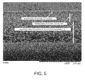
- a SEM cross-sectional view of the membrane is shown in Figure 5 .
- the isometric layer is 10 ⁇ m thick, and the pore diameter is 0.3 ⁇ m.
- the interface layer is 43 ⁇ m thick, with the region of the interface layer contacting the first isometric layer having 0.3 ⁇ m pore diameter cells, the region of the interface layer contacting the asymmetric layer having 0.5 ⁇ m pore diameter cells, and the region of the interface layer between the two regions having a pore diameter of 0.5 ⁇ m.
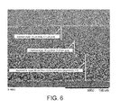
- This example describes making a membrane according to another embodiment of the invention.
- Solution 1 (top) 10.8% PES, 5% water, 3% glycerine, 25% PEG200, 0.05% V-50 (azo initiator from Wako Chemical), 0.1% HEMA, 0.3% PEGDMA, 0.2% PTA (pentaerythritol tetraacrylate from Aldrich Chemical Company), and balance of NMP to 100%.
- Solution 2 (bottom) consists of 11% PES, 5% water, 5% PVP (k-90), 25% PEG200, and 54% NMP.
- a SEM cross-sectional view of the membrane is shown in Figure 6 .
- the isometric layer is 35 ⁇ m thick, and the pore diameter is 0.1 ⁇ m.
- the interface layer is 35 ⁇ m thick, with the region of the interface layer contacting the first isometric layer having 0.1 ⁇ m pore diameter cells, the region of the interface layer contacting the asymmetric layer having 0.5 ⁇ m pore diameter cells, and the region of the interface layer between the two regions having a pore diameter of 0.25 ⁇ m.
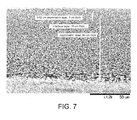
- This example describes preparing a membrane having first and second asymmetric layers, and an interface layer, wherein the first asymmetric layer has a region contacting a first portion of the interface layer, the region including cells having a first pore diameter; the second asymmetric layer has a region contacting another portion of the interface layer, the region including cells having a second pore diameter; the first pore diameter being larger than the second pore diameter; and the first portion of the interface layer comprises cells having the first pore diameter, and the second portion of the interface layer comprises cells having the second pore diameter, according to an embodiment of the invention.
- the system used for producing this membrane differs from that shown in Figure 1 in that fans are not used, i.e., the air is not circulated.
- Solution 1 (top) 10.7% Polysulfone, 16.1% t-amyl alcohol, and 73.2% DMF.
- Solution 2 (bottom) consists of 11% PES, 5% water, 5% PVP (k-90), 25% PEG200, and 54% NMP.
- Example 6 The casting conditions for Example 6 are as follows: Knife Air gap 1 (inch) 1 Knife Air gap 2 (inch) 4 Knife gap 1 (mil) 13 Knife gap 2 (mil) 12 Air Velocity (ft/min) none Quench Temp (°F) 80 Casting Speed (fpm) 5
- a SEM cross-sectional view of the membrane is shown in Figure 7 .
- the interface layer is 10 ⁇ m thick, with the region of the interface layer contacting the first asymmetric layer having 0.02 ⁇ m pore diameter cells, the region of the interface layer contacting the second asymmetric layer having 0.05 ⁇ m pore diameter cells, and the region of the interface layer between the two regions having a pore diameter of 0.1 ⁇ m.
- the Example shows the good water flow and throughput provided by a membrane according to an embodiment of the invention.
- a membrane is produced as described in Example 3. Additionally, commercially available isometric and asymmetric membranes are obtained.
- the isometric membrane is a SUPOR® 200 polyether sulfone membrane, having a pore diameter of 0.2 ⁇ m
- a 1% treacle solution is prepared (5 grams treacle (Lyle's black Treacle, Notts, UK); dissolved in 495 grams deionized water (DI)). The membranes are placed in test cells, the test system is purged, and the throughput is determined at 3 psi for 10 minutes.
- DI water flow in ml/min at 10 psi for a 90 mm disc is determined, as is the K L bubble point in psi, and the MFP (mean flow pore) size in ⁇ m.
- the inventive membrane has a 1% treacle throughput at 3 psi for 10 minutes of 220; a DI water flow of 2800 ml/min at 10 psi; a K L bubble point of 50 psi, and an MFP size of 0.27 ⁇ m.
- the isometric membrane has a 1% treacle throughput at 3 psi for 10 minutes of 10; a DI water flow of 1200 ml/min at 10 psi; a K L bubble point of 55 psi, and an MFP size of 0.25 ⁇ m.
- the asymmetric membrane has a 1% treacle throughput at 3 psi for 10 minutes of 45; a DI water flow of 1600 ml/min at 10 psi; a K L bubble point of 55 psi, and an MFP size of 0.24 ⁇ m.
Abstract
Description
- Membranes having isotropic (symmetric) and anisotropic (asymmetric) structures, e.g., multiple layer and composite membranes, are known in the art. However, conventional membranes have not been suitable for some applications, e.g., they have not reliably provided one or more of the following: desired throughput, sterility grade filtration, and robustness.
- The present invention provides for ameliorating at least some of the disadvantages of the prior art. These and other advantages of the present invention will be apparent from the description as set forth below.
- An embodiment of the invention provides a microfiltration membrane comprising (a) an asymmetric polymeric layer, (b) an isometric polymeric layer, and (c) an interface polymeric layer between the asymmetric layer and the isometric layer, the interface layer having a first portion contacting the asymmetric layer and a second portion contacting the isometric layer; wherein, (i) the asymmetric layer has a region contacting the first portion of the interface layer, the region including cells having a first porous structure; (ii) the isometric layer has a region contacting the second portion of the interface layer, the region including cells having a second porous structure; the first porous structure being larger than the second porous structure; and the first portion of the interface layer comprises cells having the first porous structure, and the second portion of the interface layer comprises cells having the second porous structure.
- In some embodiments, the asymmetric polymeric layer and the isometric polymeric layer comprise different polymers, and the interface layer includes a first polymer from the asymmetric layer and a second, different, polymer from the isometric layer.
- In some embodiments, the isometric layer has a thickness of at least about 50 micrometers and/or the asymmetric layer has a thickness in the range of about 10 to about 15 micrometers.
- In some embodiments, the isotropic layer and the interface polymeric layer are each in the range of about 15% to about 33% of the total membrane thickness, and the asymmetric layer is in the range of about 60% to about 70% of the total thickness of the membrane.
- Another embodiment of the invention provides a microfiltration membrane comprising (a) a first asymmetric polymeric layer, the first asymmetric polymeric layer having a first asymmetry ratio, (b) a second asymmetric polymeric layer, the second asymmetric polymeric layer having a second asymmetry ratio, wherein the second asymmetry ratio is greater than the first asymmetry ratio; and (c) an interface polymeric layer between the first asymmetric layer and the second asymmetric layer, the interface layer having a first portion contacting the first asymmetric layer and a second portion contacting the second asymmetric layer; wherein, (i) the first asymmetric layer has a region contacting the first portion of the interface layer, the region including cells having a first pore diameter; (ii) the second asymmetric layer has a region contacting the second portion of the interface layer, the region including cells having a second pore diameter; the first pore diameter being larger than the second pore diameter; and the first portion of the interface layer comprises cells having the first pore diameter, and the second portion of the interface layer comprises cells having the second pore diameter.
- In some embodiments, the first asymmetric polymeric layer and the second asymmetric polymeric layer comprise different polymers, and the interface layer includes a first polymer from the first asymmetric layer and a second, different, polymer from the second asymmetric layer.
- In some embodiments, the first asymmetric polymeric layer has an asymmetry ratio in the range of about 0.5 to about 1.5 and/or the second asymmetric polymeric layer has an asymmetry ratio of about 2 or more.
- In some embodiments including first and second asymmetric layers, the first asymmetric layer and the interface polymeric layer together are about 8% to about 15% of the total membrane thickness, and the second asymmetric layer is about 75% to about 90% of the total membrane thickness.
- In some embodiments, the membrane comprises a pleated membrane.
- A method of making a microfiltration membrane having an asymmetric layer, an isometric layer, and an interface layer, the interface layer having a first portion contacting the asymmetric layer and a second portion contacting the isometric layer according to an embodiment of the invention comprises (a) preparing a first solution comprising a first polymer and a solvent for the first polymer; (b) preparing a second solution comprising a second polymer and a solvent for the second polymer; (c) casting the first solution onto a first surface of a support; (d) after a short time interval, casting the second solution on the first solution and forming a pre-membrane; (e) exposing the pre-membrane to circulating air; and, (f) effecting phase separation of the first solution and the second solution in a nonsolvent liquid. The first and second polymers can be the same, or different.
- In another embodiment, a method of making a microfiltration membrane having a first asymmetric layer having a first asymmetry ratio, a second asymmetric layer having a second asymmetry ratio wherein the second asymmetry ratio is greater than the first asymmetry ratio, and an interface layer, the interface layer having a first portion contacting the first asymmetric layer and a second portion contacting the second asymmetric layer according to an embodiment of the invention comprises (a) preparing a first solution comprising a first polymer and a solvent for the first polymer; (b) preparing a second solution comprising a second polymer and a solvent for the second polymer; (c) casting the first solution onto a first surface of a support; (d) after a short time interval, casting the second solution on the first solution and forming a pre-membrane; and, (e) effecting phase separation of the first solution and the second solution in a nonsolvent liquid. The first and second polymers can be the same, or different.
- In another embodiment, a method of using the membrane, e.g., to process fluid, is provided.
-
Figure 1 shows an illustrative generalized system for preparing membranes according to an embodiment of the invention, showing a bed, first and second slot dies, fans, and a quench bath. -
Figure 2 shows a scanning electron microscope (SEM) cross-sectional view of an embodiment of a membrane according to the present invention, wherein the membrane has an isometric layer, an asymmetric layer, and an interface layer. -
Figure 3 shows a scanning electron microscope (SEM) cross-sectional view of another embodiment of a membrane according to the present invention, wherein the membrane has an isometric layer, an asymmetric layer, and an interface layer. -
Figure 4 shows another SEM cross-sectional view of an embodiment of a membrane according to another embodiment of the present invention, wherein the membrane has an isometric layer, an asymmetric layer, and an interface layer. -
Figure 5 shows a scanning electron microscope (SEM) cross-sectional view of another embodiment of a membrane according to the present invention, wherein the membrane has an isometric layer, an asymmetric layer, and an interface layer. -
Figure 6 shows another SEM cross-sectional view of another embodiment of a membrane according to the present invention, wherein the membrane has an isometric layer, an asymmetric layer, and an interface layer. -
Figure 7 shows another SEM cross-sectional view of another embodiment of a membrane according to the present invention, wherein the membrane has first and second asymmetric layers, and an interface layer. - Advantageously, membranes according to the invention have (a) an asymmetric layer including a narrow asymmetry range with a gradual change in asymmetry, a sharp demarcation between the pore structures in the asymmetric layer and in the isometric layer, and good adhesion between the layers; or (b) a first asymmetric layer including a narrow asymmetry range with a gradual change in asymmetry and a second asymmetric layer including a wider asymmetry range, a sharp demarcation between the pore structures in the first asymmetric layer and in the second asymmetric layer, and good adhesion between the layers. As a result, robust membranes exhibiting high throughput, and, if desired, providing sterile grade filtration, can be obtained.
- In accordance with an embodiment of the present invention, a microfiltration membrane is provided, comprising (a) an asymmetric polymeric layer, (b) an isometric polymeric layer, and (c) an interface polymeric layer between the asymmetric layer and the isometric layer, the interface layer having a first portion contacting the asymmetric layer and a second portion contacting the isometric layer; wherein, (i) the asymmetric layer has a region contacting the first portion of the interface layer, the region including cells having a first pore diameter; (ii) the isometric layer has a region contacting the second portion of the interface layer, the region including cells having a second pore diameter; the first pore diameter being larger than the second pore diameter; and the first portion of the interface layer comprises cells having the first pore diameter, and the second portion of the interface layer comprises cells having the second pore diameter.
- In some embodiments, the asymmetric polymer layer has a first concentration and/or a first viscosity of a polymer, the isometric polymeric layer has a second concentration and/or a second viscosity of a polymer, and interface layer comprises a mixture of the first and second concentrations and/or a mixture of the first and second viscosities of the polymer.
- Alternatively, or additionally, in some embodiments, the interface membrane includes a first polymer from the asymmetric layer and a second, different, polymer from the isometric layer.
- In some embodiments of the membrane, the isometric layer has a thickness of at least about 50 micrometers and/or the asymmetric layer has a thickness in the range of about 10 to about 15 micrometers.
- In an embodiment, the asymmetric layer is at least about 70% of the membrane thickness and/or the isometric layer is at least about 30% of the membrane thickness.
- The asymmetric layer of the membrane can have an asymmetry of about 2 or more, or about 3 or more. In some embodiments, the asymmetry is in the range of from about 10 to about 20.
- Another embodiment of the invention provides a microfiltration membrane comprising (a) a first asymmetric polymeric layer, the first asymmetric polymeric layer having a first asymmetry ratio, (b) a second asymmetric polymeric layer, the second asymmetric polymeric layer having a second asymmetry ratio, wherein the second asymmetry ratio is greater than the first asymmetry ratio; and (c) an interface polymeric layer between the first asymmetric layer and the second asymmetric layer, the interface layer having a first portion contacting the first asymmetric layer and a second portion contacting the second asymmetric layer; wherein, (i) the first asymmetric layer has a region contacting the first portion of the interface layer, the region including cells having a first pore diameter; (ii) the second asymmetric layer has a region contacting the second portion of the interface layer, the region including cells having a second pore diameter; the first pore diameter being larger than the second pore diameter; and the first portion of the interface layer comprises cells having the first pore diameter, and the second portion of the interface layer comprises cells having the second pore diameter.
- In some embodiments, the first asymmetric polymeric layer and the second asymmetric polymeric layer comprise different polymers, and the interface layer includes a first polymer from the first asymmetric layer and a second, different, polymer from the second asymmetric layer.
- In some embodiments, the first asymmetric polymeric layer has an asymmetry ratio in the range of about 0.5 to about 1.5 and/or the second asymmetric polymeric layer has an asymmetry ratio of about 2 or more.
- In some embodiments, the membrane comprises a pleated membrane.
- In another embodiment, a method of using the membrane is provided. For example, a method of processing a fluid according to an embodiment of the invention comprises passing the fluid into the membrane, in the direction from the asymmetric layer toward the isometric layer, or in the direction from the second asymmetric layer toward the first asymmetric layer, in a more preferred embodiment, the method comprises passing the fluid through the membrane.
- In yet another embodiment, a method of making a microfiltration membrane having an asymmetric layer, an isometric layer, and an interface layer, the interface layer having a first portion contacting the asymmetric layer and a second portion contacting the isometric layer, comprises (a) preparing a first solution comprising a first polymer and a solvent for the first polymer; (b) preparing a second solution comprising a second polymer and a solvent for the second polymer; (c) casting the first solution onto a first surface of a support; (d) after about 2 seconds, casting the second solution on the first solution and forming a pre-membrane; (e) exposing the pre-membrane to circulating air; and, (f) effecting phase separation of the first solution and the second solution in a nonsolvent liquid.
- In another embodiment, a method of making a microfiltration membrane having a first asymmetric layer having a first asymmetry ratio, a second asymmetric layer having a second asymmetry ratio wherein the second asymmetry ratio is greater than the first asymmetry ratio, and an interface layer, the interface layer having a first portion contacting the first asymmetric layer and a second portion contacting the second asymmetric layer according to an embodiment of the invention comprises (a) preparing a first solution comprising a first polymer and a solvent for the first polymer; (b) preparing a second solution comprising a second polymer and a solvent for the second polymer; (c) casting the first solution onto a first surface of a support; (d) after a short time interval, casting the second solution on the first solution and forming a pre-membrane; and, (e) effecting phase separation of the first solution and the second solution in a nonsolvent liquid. The first and second polymers can be the same, or different.
- The first and second polymers can be the same, or different. In some embodiments of the method, the first solution has a first concentration and/or a first viscosity of the first polymer, and the second solution has a second concentration and/or a second viscosity of the second polymer.
- In a preferred embodiment of the method casting the first solution comprises casting the first solution through first preset gap provided by a first slot die or a first casting knife, and casting the second solution comprises casting the second solution through a second preset gap provided by a second slot die or a second casting knife.
- In a more preferred embodiment of the method, at least one solution comprises a polysulfone.
- Each of the components of the invention will now be described in more detail below, wherein like components have like reference numbers.
- The solutions comprising the polymers are typically cast into thin films, one on top of the other, exposed to a gaseous environment for a predetermined period of time, followed by quenching in a nonsolvent for the polymers. Preferably, the first solution is spread in a layer (bottom layer) onto a support (such as a nonporous support), and the second solution is spread in a layer (upper layer) onto the first solution, and the membrane can be later separated from the support after quenching. However, the support (porous or non-porous) can be incorporated into the final structure if desired.
- The membranes can be cast manually (e.g., poured, cast, or spread by hand onto a casting surface and quench liquid applied onto the surface) or automatically (e.g., poured or otherwise cast onto a moving bed). One example of a suitable support is polyethylene coated paper.
- There should be a time interval of greater than 1 second, preferably greater than 1.5 seconds, between casting the first solution, and casting the second solution on the first solution. Preferably, the time interval is about 2 seconds or more. For example, the time interval can be in the range of from about 2 seconds to about 35 seconds, or about 2 seconds to about 10 seconds.
- A variety of devices known in the art can be used for casting. Suitable devices include, for example, mechanical spreaders, that comprise spreading knives, doctor blades, or spray/pressurized systems. One example of a spreading device is an extrusion die or slot coater, comprising a casting chamber into which the casting formulation (solution comprising a polymer) can be introduced and forced out under pressure through a narrow slot. Illustratively, the first and second solutions comprising polymers can be separately cast by means of a doctor blade with knife gaps in the range from about 120 micrometers to about 500 micrometers, more typically in the range from about 180 micrometers to about 400 micrometers. The knife gaps can be different for the first and second solutions.
- A variety of air gaps are suitable for use in the invention, and the air gaps can be the same for the same for the knives/doctor blades, or different. Typically, the air gaps are in the range of from about 3 inches to about 12 inches, more typically, in the range of from about 3.5 inches to about 6 inches.
- A variety of casting speeds are suitable as is known in the art. Typically, the casting speed is at least about 2 feet per minute (fpm), e.g., with knife air gaps of at least about 3 inches.
- Illustratively, using a time interval of about 2 seconds between casting the first and second solutions, the air gap can be in the range of from about 4 inches 16 inches, with casting speeds in the range of from about 2.5 fpm to about 10 fpm. In another illustration, using a time interval of about 10 seconds between casting the first and second solutions, the air gap can be in the range of from about 4 inches 8 inches, with casting speeds in the range of from about 10 fpm to about 20 fpm. Of course, the time interval can be longer than about 2 seconds, and the air gaps and/or casting speeds can be less or greater than the illustrative values listed above.
- Preferably, the cast solutions are exposed to air after casting but before quenching. The air exposure time is typically in the range of from about 2 seconds to about 35 seconds. Typically, the air is humid (e.g., greater than about 60% relative humidity). Preferably, in those embodiments wherein the membrane comprises an asymmetric layer and an isometric layer, the air, e.g., humid air, is circulated (for example, using one or more fans) to enhance contact with the cast solutions. Preferably, in those embodiments wherein the membrane comprises a first asymmetric layer and a second asymmetric layer, the air is not circulated.
- The support with the cast solutions thereon is immersed in a quenching bath to effect phase separation of the polymer solutions in a continuously layered sequence to form an integral multilayer (i.e., layers bonded together such that the membrane behaves as a single structure that does not delaminate or separate under normal use conditions) microporous polymeric membrane. After formation, the membrane is typically washed (e.g., in deionized water) to remove residual solvent), dried, and wound onto a core.
- The quenching liquid is typically water, the temperature of which is typically greater than that of the casting temperature. In the quenching bath, precipitation or coagulation occurs from the liquid film surface that first contacts the bath and then through the subsequent layer. Each layer dilutes and changes the quenching fluid as the quenching fluid diffuses through the layers.
- Suitable solutions including polymers can include polymers such as, for example, polyaromatics; sulfones (e.g., polysulfones, including aromatic polysulfones such as, for example, polyethersulfone (PES), bisphenol A polysulfone, polyarylsulfone, and polyphenylsulfone), polyamides, polyimides, polyvinylidene halides (including polyvinylidene fluoride (PVDF)), polyolefins, such as polypropylene and polymethylpentene, polyesters, polystyrenes, polycarbonates, polyacrylonitriles (including polyalkylacrylonitriles), cellulosic polymers (such as cellulose acetates and cellulose nitrates), fluoropolymers, and PEEK. Solutions comprising polymers can include a mixture of polymers, e.g., a hydrophobic polymer (e.g., a sulfone polymer) and a hydrophilic polymer (e.g., polyvinylpyrrolidone).
- Typically, the solutions comprising polymers have optical densities of about 0.05 or greater at room temperatures at 310 nm, e.g., the densities can be in the range of from about 0.01 to about 0.3 at 310 nm. In some embodiments, the first cast solution (forming the bottom layer) has a higher optical density than the later cast solution (forming an upper layer).
- In addition to one or more polymers, typical solutions comprise at least one solvent, and may further comprise at least one non-solvent. Suitable solvents include, for example, dimethyl formamide (DMF); N,N-dimethylacetamide (DMAC); N-methyl pyrrolidone (NMP); tetramethylurea; dioxane; diethyl succinate; dimethylsulfoxide; chloroform; and tetrachloroethane; and mixtures thereof. Suitable nonsolvents include, for example, water; various polyethylene glycols (PEGs; e.g., PEG-400, PEG-1000); various alcohols, e.g., methanol, ethanol, isopropyl alcohol (IPA), amyl alcohols, hexanols, heptanols, and octanols; alkanes, such as hexane, propane, nitropropane, heptanes, and octane; and ketone, ethers and esters such as acetone, butyl ether, ethyl acetate, and amyl acetate; and various salts, such as calcium chloride, magnesium chloride, and lithium chloride; and mixtures thereof.
- If desired, a solution comprising a polymer can further comprise, for example, one or more polymerization initiators (e.g., any one or more of peroxides, ammonium persulfate, aliphatic azo compounds (e.g., 2,2'-azobis(2-amidinopropane) dihydrochloride (V50)), and combinations thereof), and/or minor ingredients such as surfactants and/or release agents.
- Suitable components of solutions are known in the art. Illustrative solutions comprising polymers, and illustrative solvents and nonsolvents include those disclosed in, for example,
U.S. Patents 5,846,422 ;5,906,742 ;5,928,774 ;6,045,899 ; and6,146,747 . - In accordance with the invention, layers of the membrane can be formed from the same polymer and solvent, varying the viscosity, additives, and treatment, or different polymers can be used for different layers.
- An isometric layer has a porous structure with a distribution characterized by an average pore structure that is substantially the same through the layer. For example, with respect to pore diameter, an isometric layer has a pore diameter distribution characterized by a pore diameter that is substantially the same through the layer.
- An asymmetric layer has a pore structure (typically, a pore diameter) varying throughout the layer. Typically, the pore diameter decreases in diameter from one portion or surface to another portion or surface (e.g., the pore diameter of the cells decreases from the upstream portion or surface to the downstream portion or surface). However, other types of asymmetry are encompassed by embodiments of the invention, e.g., the pore diameter goes through a minimum pore diameter at a position within the thickness of the asymmetric layer. The asymmetric layers can have any suitable pore diameter gradient or ratio, e.g., about 0.5 or more, about 3 or more, or about 7 or more, or in the range from about 0.5 to about 1.5, about 2:1 to about 20:1, or in the range of from about 3:1 to about 10:1. This asymmetry can be measured by comparing the pore diameter on one major surface of a layer with the pore diameter of the other major surface of that layer.
- Typically, an isotropic layer has a pore structure (typically, a pore diameter) in the range of from about 0.02 micrometers to about 0.3 micrometers.
- The thickness of each layer can be varied within a wide range while still obtaining a self-supporting, integral multilayer membrane. Typically, the multilayer membrane has a thickness of at least about 50 micrometers, more typically, at least about 75 micrometers, and preferably, at least about 100 micrometers. Typically, in those embodiments including an isotropic layer, the isotropic layer and interface polymeric layers are each in the range of about 15% to about 33% of the total membrane thickness, and the asymmetric layer is in the range of about 60% to about 70% of the total thickness of the membrane. Typically, in those embodiments including first and second asymmetric layers, the first asymmetric layer and interface polymeric layers together are about 8% to about 15% of the total membrane thickness, and the second asymmetric layer is about 75% to about 90% of the total membrane thickness.
- In accordance with embodiments of the invention, filters and filter elements are also provided, wherein the filter and filter elements comprise at least one membrane according to the invention.
- A membrane according to the invention, (as well as filter element comprising at least one membrane) can have any suitable pore structure, e.g., a pore size (for example, as evidenced by porometry (for example, mercury porometry or capillary condensation flow porometry), or by bubble point, or by KL as described in, for example,
U.S. Patent 4,340,479 ), a pore rating, a pore diameter (e.g., when characterized using the modified OSU F2 test as described in, for example,U.S. Patent 4,925,572 , or using a porometer), or removal rating that reduces or allows the passage therethrough of one or more materials of interest as the fluid is passed through the element. The desired pore structure depends on the composition of the fluid to be treated, and the desired effluent level of the treated fluid. - The membrane can have any desired critical wetting surface tension (CWST, as defined in, for example,
U.S. Patent 4,925,572 ). The CWST can be selected as is known in the art, e.g., as additionally disclosed in, for example,U.S. Patents 5,152,905 ,5,443,743 ,5,472,621 , and6,074,869 . For applications wherein liquid passes through the membrane, the membrane is preferably hydrophilic (either as made, or post-treatment), having a CWST of 72 dynes/cm (72 x 10-5 N/cm) or more, more preferably, having a CWST of about 78 dynes/cm (about 78 x 10-5 N/cm) or more. However, for some other application wherein liquid does not pass through the membrane (e.g., for venting applications), the membrane can be hydrophobic, having a CWST of less than 72 dynes/cm (72 x 10-5 N/cm). - The surface characteristics of the membrane can be modified (e.g., to affect the CWST, to include a surface charge, e.g., a positive or negative charge, and/or to alter the polarity or hydrophilicity of the surface) by wet or dry oxidation, by coating or depositing a polymer on the surface, or by a grafting reaction. Modifications include, e.g., irradiation, a polar or charged monomer, coating and/or curing the surface with a charged polymer, and carrying out chemical modification to attach functional groups on the surface. Grafting reactions may be activated by exposure to an energy source such as gas plasma, vapor plasma, corona discharge, heat, a Van der Graff generator, ultraviolet light, electron beam, or to various other forms of radiation, or by surface etching or deposition using a plasma treatment.
- Membranes according to embodiments of the invention can be used in a variety of applications, including, for example, sterile filtration applications, filtering fluids for the electronics industry, filtering fluids for the pharmaceutical industry, filtering fluids for the food and beverage industry, clarification, filtering antibody- and/or protein-containing fluids, filtering cell culture fluids, and venting.
- A filter and/or a filter element comprising at least one membrane according to the invention can include additional elements, layers, or components, that can have different structures and/or functions, e.g., at least one of prefiltration, support, drainage, spacing and cushioning. Illustratively, the filter can also include at least one additional element such as a mesh and/or a screen.
- In accordance with embodiments of the invention, the membrane, filter, and/or filter element can have a variety of configurations, including planar, pleated, and hollow cylindrical.
- The filter, in some embodiments comprising a plurality of filter elements is typically disposed in a housing comprising at least one inlet and at least one outlet and defining at least one fluid flow path between the inlet and the outlet, wherein the filter is across the fluid flow path, to provide a filter device. Preferably, the filter device is sterilizable. Any housing of suitable shape and providing at least one inlet and at least one outlet may be employed.
- The following examples further illustrate the invention but, of course, should not be construed as in any way limiting its scope.
- In the following Examples, membranes are produced using a system arranged as generally shown in
Figure 1 . The casting solutions are described in the respective examples. Membranes are cast onto paper using a casting knife.Knife 1 andknife 2 are used at preset air gaps and the conditions as listed below. Six fans are used to provide air velocity. Following casting, the membranes are quenched in a water bath (quench temperature of the water bath is 105° F (about 41°C)) for about 6 minutes till membrane is coagulated. The membranes are further washed with deionized water overnight and then oven dried. - The pore diameters are analyzed using a Quantachrome PoreMaster® Series mercury intrusion porosimeter (Boynton Beach, FL), and a Porvair Porometer (Porvair plc, Norfolk, UK).
- The casting conditions for Examples 1-5 are as follows:
Example 1 Ex. 2 Ex. 3 Ex. 4 Ex. 5 Knife air gap 1 (inch) 4 4 4 4 3 Knife air gap 2 (inch) 4 4 4 4 4 Knife gap 1 (mil) 12 12 12 12 12 Knife gap 2 (mil) 10 9 10 10 9 Air velocity (ft/min) 50 50 70 100 100 Quench Temp (°F) 105 105 105 105 105 Casting Speed (fpm) 9 9 9 9 11 - This example describes making a membrane having an isometric polymeric layer, an asymmetric polymer layer, and an interface layer, wherein the asymmetric layer has a region contacting a first portion of the interface layer, the region including cells having a first pore diameter; the isometric layer has a region contacting another portion of the interface layer, the region including cells having a second pore diameter; the first pore diameter being larger than the second pore diameter; and the first portion of the interface layer comprises cells having the first pore diameter, and the second portion of the interface layer comprises cells having the second pore diameter, according to an embodiment of the present invention.
- Solution 1 (top) consists of 11.5% PES, 5% water, 0.5% sulfonated PES (SPES), 3% PVP (polyvinyl pyrrolidone) (k-90), 25% PEG200, and 55% NMP. Solution 2 (bottom) consists of 11% PES, 5% water, 5% PVP (k-90), 25% PEG200, and 54% NMP.
- A SEM cross-sectional view of the membrane is shown in
Figure 2 . - The isometric layer is 19 micrometers (µm) thick, and the pore diameter is 0.15 µm. The interface layer is 7 µm thick, with the region of the interface layer contacting the isometric layer having 0.15 µm pore diameter cells, the region of the interface layer contacting the asymmetric layer having 1 µm pore diameter cells, and the region of the interface layer between the two regions having a pore diameter of 0.5 µm. The asymmetric layer is 111 µm thick, with the region of the asymmetric layer contacting the interface layer having a pore diameter of 1 µm, and the other surface of the asymmetric layer having a pore diameter of 10 µm (asymmetry ratio = 10).
- This example describes making a membrane having an isometric polymeric layer, an asymmetric polymer layer, and an interface layer, wherein the asymmetric layer has a region contacting a first portion of the interface layer, the region including cells having a first pore diameter; the isometric layer has a region contacting another portion of the interface layer, the region including cells having a second pore diameter; the first pore diameter being larger than the second pore diameter; and the first portion of the interface layer comprises cells having the first pore diameter, and the second portion of the interface layer comprises cells having the second pore diameter, according to another embodiment of the present invention.
- Solution 1 (top) consists of 11.5% PES, 5% water, 0.5% sulfonated PES (SPES), 3% PVP (k-90), 25% PEG200, and 55% NMP. Solution 2 (bottom) consists of 11% PES, 5% water, 5% PVP (k-90), 25% PEG200, and 54% NMP.
- A SEM cross-sectional view of the membrane is shown in
Figure 3 . - The isometric layer is 12 µm thick, and the pore diameter is 0.15 µm. The interface layer is 39 µm thick, with the region of the interface layer contacting the isometric layer having 0.15 µm pore diameter cells, the region of the interface layer contacting the asymmetric layer having 0.6 µm pore diameter cells, and the region of the interface layer between the two regions having a pore diameter of 0.5 µm. The asymmetric layer is 81 µm thick, with the region of the asymmetric layer contacting the interface layer having a pore diameter of 0.6 µm, and the other surface of the asymmetric layer having a pore diameter of 3 µm (asymmetry ratio = 5).
- This example describes making a membrane according to another embodiment of the invention, the membrane having an isometric polymeric layer, an asymmetric polymer layer, and an interface layer, wherein the asymmetric layer has a region contacting a first portion of the interface layer, the region including cells having a first pore diameter; the isometric layer has a region contacting another portion of the interface layer, the region including cells having a second pore diameter; the first pore diameter being larger than the second pore diameter; and the first portion of the interface layer comprises cells having the first pore diameter, and the second portion of the interface layer comprises cells having the second pore diameter.
- Solution 1 (top) consists of 11.5% PES, 5% water, 0.5% sulfonated PES (SPES), 3% PVP (k-90), 25% PEG200, and 55% NMP. Solution 2 (bottom) consists of 11% PES, 5% water, 5% PVP (k-90), 25% PEG200, and 54% NMP.
- A SEM cross-sectional view of the membrane is shown in
Figure 4 . - The isometric layer is 7 µm thick, and the pore diameter is 0.5 µm. The interface layer is 12 µm thick, with the region of the interface layer contacting the isometric layer having 0.5 µm pore diameter cells, the region of the interface layer contacting the asymmetric layer having 1 µm pore diameter cells, and the region of the interface layer between the two regions having a pore diameter of 0.15 µm. The asymmetric layer is 104 µm thick, with the region of the asymmetric layer contacting the interface layer having a pore diameter of 1 µm, and the other surface of the asymmetric layer having a pore diameter of 10 µm (asymmetry ratio = 10).
- This example describes making a membrane according to another embodiment of the invention.
- Solution 1 (top) 10.8% PES, 5% water, 3% glycerine, 25% PEG200, 0.05% V-50 (2,2'-azobis(2-amidinopropane) dihydrochloride azo initiator from Wako Chemical, Richmond, VA), 0.1% HEMA (hydroxylethylmethacrylate), 0.3% PEGDMA (polyethylene glycol dimethacrylate), 0.2% PTA (pentaerythritol tetraacrylate from Aldrich Chemical Co., Milwaukee, WI), and balance of NMP to 100%. Solution 2 (bottom) consists of 11% PES, 5% water, 5% PVP (k-90), 25% PEG200, and 54% NMP.
- A SEM cross-sectional view of the membrane is shown in
Figure 5 . - The isometric layer is 10 µm thick, and the pore diameter is 0.3 µm. The interface layer is 43 µm thick, with the region of the interface layer contacting the first isometric layer having 0.3 µm pore diameter cells, the region of the interface layer contacting the asymmetric layer having 0.5 µm pore diameter cells, and the region of the interface layer between the two regions having a pore diameter of 0.5 µm. The asymmetric layer is 65 µm thick, with the region of the asymmetric layer contacting the interface layer having a pore diameter of 0.5 µm, and the other surface of the asymmetric layer having a pore diameter of 2 µm (asymmetry ratio = 4).
- This example describes making a membrane according to another embodiment of the invention.
- Solution 1 (top) 10.8% PES, 5% water, 3% glycerine, 25% PEG200, 0.05% V-50 (azo initiator from Wako Chemical), 0.1% HEMA, 0.3% PEGDMA, 0.2% PTA (pentaerythritol tetraacrylate from Aldrich Chemical Company), and balance of NMP to 100%. Solution 2 (bottom) consists of 11% PES, 5% water, 5% PVP (k-90), 25% PEG200, and 54% NMP.
- A SEM cross-sectional view of the membrane is shown in
Figure 6 . - The isometric layer is 35 µm thick, and the pore diameter is 0.1 µm. The interface layer is 35 µm thick, with the region of the interface layer contacting the first isometric layer having 0.1 µm pore diameter cells, the region of the interface layer contacting the asymmetric layer having 0.5 µm pore diameter cells, and the region of the interface layer between the two regions having a pore diameter of 0.25 µm. The asymmetric layer is 65 µm thick, with the region of the asymmetric layer contacting the interface layer having a pore diameter of 0.5 µm, and the other surface of the asymmetric layer having a pore diameter of 2 µm (asymmetry ratio = 4).
- This example describes preparing a membrane having first and second asymmetric layers, and an interface layer, wherein the first asymmetric layer has a region contacting a first portion of the interface layer, the region including cells having a first pore diameter; the second asymmetric layer has a region contacting another portion of the interface layer, the region including cells having a second pore diameter; the first pore diameter being larger than the second pore diameter; and the first portion of the interface layer comprises cells having the first pore diameter, and the second portion of the interface layer comprises cells having the second pore diameter, according to an embodiment of the invention.
- The system used for producing this membrane differs from that shown in
Figure 1 in that fans are not used, i.e., the air is not circulated. - The following solutions are used:
- Solution 1 (top) 10.7% Polysulfone, 16.1% t-amyl alcohol, and 73.2% DMF. Solution 2 (bottom) consists of 11% PES, 5% water, 5% PVP (k-90), 25% PEG200, and 54% NMP.
- The casting conditions for Example 6 are as follows:
Knife Air gap 1 (inch) 1 Knife Air gap 2 (inch) 4 Knife gap 1 (mil) 13 Knife gap 2 (mil) 12 Air Velocity (ft/min) none Quench Temp (°F) 80 Casting Speed (fpm) 5 - A SEM cross-sectional view of the membrane is shown in
Figure 7 . - The first asymmetric layer is 7 µm thick, and the portion of the first asymmetric layer contacting the interface layer has cells with a pore diameter of 0.02 µm and the pore diameter at the other surface is 0.5 µm (asymmetry ratio = 25).
- The interface layer is 10 µm thick, with the region of the interface layer contacting the first asymmetric layer having 0.02 µm pore diameter cells, the region of the interface layer contacting the second asymmetric layer having 0.05 µm pore diameter cells, and the region of the interface layer between the two regions having a pore diameter of 0.1µm. The second asymmetric layer is 85 µm thick, with the region of the asymmetric layer contacting the interface layer having a pore diameter of 0.1µm, and the other surface of the asymmetric layer having a pore diameter of 0.5 µm (asymmetry ratio = 5).
- The Example shows the good water flow and throughput provided by a membrane according to an embodiment of the invention.
- A membrane is produced as described in Example 3. Additionally, commercially available isometric and asymmetric membranes are obtained. The isometric membrane is a
SUPOR® 200 polyether sulfone membrane, having a pore diameter of 0.2 µm, and the asymmetric membrane is a BTS-55 polysulfone membrane, having a pore diameter at the skin surface of 0.2 µm, and a pore diameter at the other surface of 20 µm (asymmetry ratio = 10), both available from Pall Corporation (East Hills, NY). - A 1% treacle solution is prepared (5 grams treacle (Lyle's black Treacle, Notts, UK); dissolved in 495 grams deionized water (DI)). The membranes are placed in test cells, the test system is purged, and the throughput is determined at 3 psi for 10 minutes.
- Additionally, the DI water flow in ml/min at 10 psi for a 90 mm disc is determined, as is the KL bubble point in psi, and the MFP (mean flow pore) size in µm.
- The results are as follows:
- The inventive membrane has a 1% treacle throughput at 3 psi for 10 minutes of 220; a DI water flow of 2800 ml/min at 10 psi; a KL bubble point of 50 psi, and an MFP size of 0.27 µm.
- The isometric membrane has a 1% treacle throughput at 3 psi for 10 minutes of 10; a DI water flow of 1200 ml/min at 10 psi; a KL bubble point of 55 psi, and an MFP size of 0.25 µm.
- The asymmetric membrane has a 1% treacle throughput at 3 psi for 10 minutes of 45; a DI water flow of 1600 ml/min at 10 psi; a KL bubble point of 55 psi, and an MFP size of 0.24 µm.
- All references, including publications, patent applications, and patents, cited herein are hereby incorporated by reference to the same extent as if each reference were individually and specifically indicated to be incorporated by reference and were set forth in its entirety herein.
- The use of the terms "a" and "an" and "the" and similar referents in the context of describing the invention (especially in the context of the following claims) are to be construed to cover both the singular and the plural, unless otherwise indicated herein or clearly contradicted by context. The terms "comprising," "having," "including," and "containing" are to be construed as open-ended terms (i.e., meaning "including, but not limited to,") unless otherwise noted. Recitation of ranges of values herein are merely intended to serve as a shorthand method of referring individually to each separate value falling within the range, unless otherwise indicated herein, and each separate value is incorporated into the specification as if it were individually recited herein. All methods described herein can be performed in any suitable order unless otherwise indicated herein or otherwise clearly contradicted by context. The use of any and all examples, or exemplary language (e.g., "such as") provided herein, is intended merely to better illuminate the invention and does not pose a limitation on the scope of the invention unless otherwise claimed. No language in the specification should be construed as indicating any non-claimed element as essential to the practice of the invention.
- Preferred embodiments of this invention are described herein, including the best mode known to the inventors for carrying out the invention. Variations of those preferred embodiments may become apparent to those of ordinary skill in the art upon reading the foregoing description. The inventors expect skilled artisans to employ such variations as appropriate, and the inventors intend for the invention to be practiced otherwise than as specifically described herein. Accordingly, this invention includes all modifications and equivalents of the subject matter recited in the claims appended hereto as permitted by applicable law. Moreover, any combination of the above-described elements in all possible variations thereof is encompassed by the invention unless otherwise indicated herein or otherwise clearly contradicted by context.
Claims (13)
- A microfiltration membrane comprising(a) an asymmetric polymeric layer,(b) an isometric polymeric layer, and(c) an interface polymeric layer between the asymmetric layer and the isometric layer, the interface layer having a first portion contacting the asymmetric layer and a second portion contacting the isometric layer;
wherein,(i) the asymmetric layer has a region contacting the first portion of the interface layer, the region including cells having a first pore diameter;(ii) the isometric layer has a region contacting the second portion of the interface layer, the region including cells having a second pore diameter;
the first pore diameter being larger than the second pore diameter; and the first portion of the interface layer comprises cells having the first pore diameter, and the second portion of the interface layer comprises cells having the second pore diameter. - The membrane of claim 1, wherein the asymmetric layer has an asymmetry of about 2 or more.
- A microfiltration membrane comprising(a) a first asymmetric polymeric layer, the first asymmetric polymeric layer having a first asymmetry ratio,(b) a second asymmetric polymeric layer, the second asymmetric polymeric layer having a second asymmetry ratio, wherein the second asymmetry ratio is greater than the first asymmetry ratio; and(c) an interface polymeric layer between the first asymmetric layer and the second asymmetric layer, the interface layer having a first portion contacting the first asymmetric layer and a second portion contacting the second asymmetric layer;
wherein,(i) the first asymmetric layer has a region contacting the first portion of the interface layer, the region including cells having a first pore diameter;(ii) the second asymmetric layer has a region contacting the second portion of the interface layer, the region including cells having a second pore diameter;
the first pore diameter being larger than the second pore diameter; and the first portion of the interface layer comprises cells having the first pore diameter, and the second portion of the interface layer comprises cells having the second pore diameter. - The microfiltration membrane of claim 3, wherein the first asymmetric polymeric layer has an asymmetry ratio in the range of from about 0.5 to about 1.5.
- The microfiltration membrane of claim 3 or 4, wherein the second asymmetric polymeric layer has an asymmetry ratio of about 2 or more.
- The membrane of any one of claims 1-5, comprising a pleated membrane.
- A method of processing a fluid, comprising passing the fluid into the membrane of any one of claims 1, 2, or 6, in the direction from the asymmetric layer toward the isometric layer.
- A method of processing a fluid, comprising passing the fluid into the membrane of any one of claims 3-6, in the direction from the second asymmetric layer toward the first asymmetric layer.
- The method of claim 7 or 8, comprising passing the fluid through the membrane.
- A method of making a microfiltration membrane having an asymmetric layer, an isometric layer, and an interface layer, the interface layer having a first portion contacting the asymmetric layer and a second portion contacting the isometric layer, comprising:(a) preparing a first solution comprising a first polymer and a solvent for the first polymer;(b) preparing a second solution comprising a second polymer and a solvent for the second polymer;(c) casting the first solution onto a first surface of a support;(d) after about 2 seconds, casting the second solution on the first solution and forming a pre-membrane;(e) exposing the pre-membrane to circulating air; and,(f) effecting phase separation of the first solution and the second solution in a nonsolvent liquid.
- A method of making a microfiltration membrane having a first asymmetric layer having a first asymmetry ratio, a second asymmetric layer having a second asymmetry ratio that is greater than the first asymmetry ratio, and an interface layer, the interface layer having a first portion contacting the first asymmetric layer and a second portion contacting the second asymmetric layer, comprising:(a) preparing a first solution comprising a first polymer and a solvent for the first polymer;(b) preparing a second solution comprising a second polymer and a solvent for the second polymer;(c) casting the first solution onto a first surface of a support;(d) after about 2 seconds, casting the second solution on the first solution and forming a pre-membrane; and,(e) effecting phase separation of the first solution and the second solution in a nonsolvent liquid.
- The method of claim 10 or 11, wherein at least one solution comprises a polysulfone.
- The method of any one of claims 10-12, wherein casting the first solution comprises casting the first solution through first preset gap provided by a first slot die or a first casting knife, and casting the second solution comprises casting the second solution through a second preset gap provided by a second slot die or a second casting knife.
Applications Claiming Priority (1)
| Application Number | Priority Date | Filing Date | Title |
|---|---|---|---|
| US13/224,002 US8840791B2 (en) | 2011-09-01 | 2011-09-01 | Multilayer microfiltration membrane |
Publications (1)
| Publication Number | Publication Date |
|---|---|
| EP2609992A1 true EP2609992A1 (en) | 2013-07-03 |
Family
ID=46754334
Family Applications (1)
| Application Number | Title | Priority Date | Filing Date |
|---|---|---|---|
| EP12182027.8A Withdrawn EP2609992A1 (en) | 2011-09-01 | 2012-08-28 | Multilayer microfiltration membrane and wet in wet method of production |
Country Status (10)
| Country | Link |
|---|---|
| US (1) | US8840791B2 (en) |
| EP (1) | EP2609992A1 (en) |
| JP (1) | JP5613911B2 (en) |
| KR (1) | KR101418504B1 (en) |
| CN (1) | CN103055709B (en) |
| AU (1) | AU2012216385A1 (en) |
| BR (1) | BR102012021684A2 (en) |
| CA (1) | CA2788174C (en) |
| SG (1) | SG188044A1 (en) |
| TW (1) | TW201318859A (en) |
Cited By (2)
| Publication number | Priority date | Publication date | Assignee | Title |
|---|---|---|---|---|
| WO2018122308A1 (en) * | 2016-12-30 | 2018-07-05 | Vito Nv (Vlaamse Instelling Voor Technologisch Onderzoek Nv) | Isotropic porous membrane and method of preparing the same |
| WO2020201228A1 (en) * | 2019-03-29 | 2020-10-08 | Nvigorea Ab | Filtration |
Families Citing this family (17)
| Publication number | Priority date | Publication date | Assignee | Title |
|---|---|---|---|---|
| US8950587B2 (en) | 2009-04-03 | 2015-02-10 | Hollingsworth & Vose Company | Filter media suitable for hydraulic applications |
| US20140339164A1 (en) * | 2013-05-14 | 2014-11-20 | Pall Corporation | High throughput membrane |
| US20140339165A1 (en) * | 2013-05-14 | 2014-11-20 | Pall Corporation | High throughput membrane with rough surface |
| US9808770B2 (en) * | 2013-05-14 | 2017-11-07 | Pall Corporation | High throughput membrane with channels |
| US9737860B2 (en) | 2014-02-28 | 2017-08-22 | Pall Corporation | Hollow fiber membrane having hexagonal voids |
| US9561473B2 (en) | 2014-02-28 | 2017-02-07 | Pall Corporation | Charged hollow fiber membrane having hexagonal voids |
| US9469737B2 (en) * | 2014-08-20 | 2016-10-18 | Pall Corporation | Robust polymeric membrane |
| CN106573203B (en) | 2014-08-25 | 2020-02-07 | 旭化成医疗株式会社 | Porous membrane |
| CN104307385B (en) * | 2014-10-15 | 2016-05-11 | 中国科学技术大学先进技术研究院 | A kind of tubular type inorganic-organic hybrid micro-filtration membrane and preparation method thereof |
| WO2017196656A1 (en) * | 2016-05-13 | 2017-11-16 | 3M Innovative Properties Company | Multilayer articles including coatings on microfiltration membrane substrates and methods of making same |
| EP3586948A1 (en) * | 2018-06-29 | 2020-01-01 | 3M Innovative Properties Company | Low protein binding polyethersulfone microfiltration membranes |
| CN108771983B (en) * | 2018-07-04 | 2021-04-27 | 青岛大学 | Multilayer through-hole high-permeability polymer microfiltration membrane and preparation method thereof |
| CN109513355B (en) * | 2018-08-27 | 2021-12-21 | 浙江工业大学 | Preparation and application of anion exchange membrane for internal crosslinking by using BMP |
| CN109012194A (en) * | 2018-09-17 | 2018-12-18 | 杭州汉膜新材料科技有限公司 | A kind of Polyethersulfone Hollow Fiber Plasma microporous barrier and preparation method |
| DE102019005373A1 (en) * | 2019-07-30 | 2021-02-04 | Sartorius Stedim Biotech Gmbh | Mechanically stable ultrafiltration membrane and process for its manufacture |
| JP2023502733A (en) | 2019-11-21 | 2023-01-25 | イーエムディ・ミリポア・コーポレイション | microfiltration membrane |
| US11241657B2 (en) * | 2019-11-22 | 2022-02-08 | Pall Corporation | Filter for removing silica from ultra pure water and method of use |
Citations (16)
| Publication number | Priority date | Publication date | Assignee | Title |
|---|---|---|---|---|
| US4340479A (en) | 1978-05-15 | 1982-07-20 | Pall Corporation | Process for preparing hydrophilic polyamide membrane filter media and product |
| US4925572A (en) | 1987-10-20 | 1990-05-15 | Pall Corporation | Device and method for depletion of the leukocyte content of blood and blood components |
| US5152905A (en) | 1989-09-12 | 1992-10-06 | Pall Corporation | Method for processing blood for human transfusion |
| US5443743A (en) | 1991-09-11 | 1995-08-22 | Pall Corporation | Gas plasma treated porous medium and method of separation using same |
| US5472621A (en) | 1992-06-10 | 1995-12-05 | Pall Corporation | Method for treating transition zone material |
| US5620790A (en) * | 1994-06-23 | 1997-04-15 | Seitz-Filter-Werke Gmbh Und Co. | Multi-layer microfiltration membrane having an integrated prefiltration layer and method of making same |
| US5846422A (en) | 1994-03-04 | 1998-12-08 | Memtec America Corporation | Large pore synthetic polymer membranes |
| US5906742A (en) | 1995-07-05 | 1999-05-25 | Usf Filtration And Separations Group Inc. | Microfiltration membranes having high pore density and mixed isotropic and anisotropic structure |
| US5928774A (en) | 1997-07-08 | 1999-07-27 | Usf Filtration And Separations Group Inc. | Highly asymmetric ultrafiltration membranes |
| US6045899A (en) | 1996-12-12 | 2000-04-04 | Usf Filtration & Separations Group, Inc. | Highly assymetric, hydrophilic, microfiltration membranes having large pore diameters |
| US6074869A (en) | 1994-07-28 | 2000-06-13 | Pall Corporation | Fibrous web for processing a fluid |
| US6146747A (en) | 1997-01-22 | 2000-11-14 | Usf Filtration And Separations Group Inc. | Highly porous polyvinylidene difluoride membranes |
| WO2001089673A2 (en) * | 2000-05-24 | 2001-11-29 | Millipore Corporation | Process of forming multilayered structures |
| US20020063093A1 (en) * | 1997-06-06 | 2002-05-30 | Koch Membrane Systems, Inc. | High performance composite membrane |
| US20020127387A1 (en) * | 2000-08-07 | 2002-09-12 | Richard Sale | Pre-metered, unsupported multilayer microporous membrane |
| EP1609522A2 (en) * | 2004-06-25 | 2005-12-28 | Millipore Corporation | Multilayer ultrafiltration composite membranes and methods of making |
Family Cites Families (18)
| Publication number | Priority date | Publication date | Assignee | Title |
|---|---|---|---|---|
| US4340480A (en) | 1978-05-15 | 1982-07-20 | Pall Corporation | Process for preparing liquophilic polyamide membrane filter media and product |
| JPS6219205A (en) | 1985-07-17 | 1987-01-28 | Nok Corp | Preparation of ultrafilter membrane |
| JPS6227006A (en) | 1985-07-27 | 1987-02-05 | Fuji Photo Film Co Ltd | Microporous membrane |
| JPH0829241B2 (en) | 1988-07-11 | 1996-03-27 | ダイセル化学工業株式会社 | Polysulfone hollow fiber membrane |
| JPH0557149A (en) | 1991-02-15 | 1993-03-09 | Fuji Photo Film Co Ltd | Filter system |
| US5228994A (en) | 1992-10-13 | 1993-07-20 | Millipore Corporation | Composite microporous membranes |
| CA2222641C (en) | 1995-06-07 | 2006-10-17 | Memtec America Corporation | Microfiltration membranes having high pore density and mixed isotropic and anisotropic structure |
| US6056529A (en) * | 1998-02-11 | 2000-05-02 | Cuno, Inc. | Systems for producing a plurality of different microporous phase inversion membrane each having any one of a plurality of different pore sizes from a single master dope batch |
| US6264044B1 (en) | 1997-04-11 | 2001-07-24 | Cuno, Inc. | Reinforced, three zone microporous membrane |
| US6994811B2 (en) * | 2001-05-22 | 2006-02-07 | Millipore Corporation | Method of manufacturing membranes and the resulting membranes |
| US7229665B2 (en) * | 2001-05-22 | 2007-06-12 | Millipore Corporation | Process of forming multilayered structures |
| JP2005506168A (en) | 2000-08-07 | 2005-03-03 | キュノ、インコーポレーテッド | Multi-zone unsupported microporous thin film |
| US6833073B2 (en) | 2001-10-09 | 2004-12-21 | Pti Advanced Filtration, Inc. | Composite nanofiltration and reverse osmosis membranes and method for producing the same |
| US6811696B2 (en) * | 2002-04-12 | 2004-11-02 | Pall Corporation | Hydrophobic membrane materials for filter venting applications |
| US20040118770A1 (en) | 2002-07-24 | 2004-06-24 | Sale Richard D. | Multiple layer membrane and method for fabrication thereof |
| US7842214B2 (en) * | 2007-03-28 | 2010-11-30 | 3M Innovative Properties Company | Process for forming microporous membranes |
| JP5698140B2 (en) | 2008-11-21 | 2015-04-08 | スリーエム イノベイティブ プロパティズ カンパニー | Microporous membrane and formation method |
| US20110042299A1 (en) | 2009-08-20 | 2011-02-24 | General Electric Company | Composite membrane assemblies and methods of making and using the same |
-
2011
- 2011-09-01 US US13/224,002 patent/US8840791B2/en not_active Expired - Fee Related
-
2012
- 2012-08-07 JP JP2012175092A patent/JP5613911B2/en not_active Expired - Fee Related
- 2012-08-07 TW TW101128405A patent/TW201318859A/en unknown
- 2012-08-07 SG SG2012058434A patent/SG188044A1/en unknown
- 2012-08-20 AU AU2012216385A patent/AU2012216385A1/en not_active Abandoned
- 2012-08-28 BR BRBR102012021684-1A patent/BR102012021684A2/en not_active Application Discontinuation
- 2012-08-28 EP EP12182027.8A patent/EP2609992A1/en not_active Withdrawn
- 2012-08-29 CA CA2788174A patent/CA2788174C/en not_active Expired - Fee Related
- 2012-08-31 KR KR1020120096295A patent/KR101418504B1/en active IP Right Grant
- 2012-08-31 CN CN201210461988.2A patent/CN103055709B/en not_active Expired - Fee Related
Patent Citations (17)
| Publication number | Priority date | Publication date | Assignee | Title |
|---|---|---|---|---|
| US4340479B1 (en) | 1978-05-15 | 1996-08-27 | Pall Corp | Process for preparing hydrophilic polyamide membrane filter media and product |
| US4340479A (en) | 1978-05-15 | 1982-07-20 | Pall Corporation | Process for preparing hydrophilic polyamide membrane filter media and product |
| US4925572A (en) | 1987-10-20 | 1990-05-15 | Pall Corporation | Device and method for depletion of the leukocyte content of blood and blood components |
| US5152905A (en) | 1989-09-12 | 1992-10-06 | Pall Corporation | Method for processing blood for human transfusion |
| US5443743A (en) | 1991-09-11 | 1995-08-22 | Pall Corporation | Gas plasma treated porous medium and method of separation using same |
| US5472621A (en) | 1992-06-10 | 1995-12-05 | Pall Corporation | Method for treating transition zone material |
| US5846422A (en) | 1994-03-04 | 1998-12-08 | Memtec America Corporation | Large pore synthetic polymer membranes |
| US5620790A (en) * | 1994-06-23 | 1997-04-15 | Seitz-Filter-Werke Gmbh Und Co. | Multi-layer microfiltration membrane having an integrated prefiltration layer and method of making same |
| US6074869A (en) | 1994-07-28 | 2000-06-13 | Pall Corporation | Fibrous web for processing a fluid |
| US5906742A (en) | 1995-07-05 | 1999-05-25 | Usf Filtration And Separations Group Inc. | Microfiltration membranes having high pore density and mixed isotropic and anisotropic structure |
| US6045899A (en) | 1996-12-12 | 2000-04-04 | Usf Filtration & Separations Group, Inc. | Highly assymetric, hydrophilic, microfiltration membranes having large pore diameters |
| US6146747A (en) | 1997-01-22 | 2000-11-14 | Usf Filtration And Separations Group Inc. | Highly porous polyvinylidene difluoride membranes |
| US20020063093A1 (en) * | 1997-06-06 | 2002-05-30 | Koch Membrane Systems, Inc. | High performance composite membrane |
| US5928774A (en) | 1997-07-08 | 1999-07-27 | Usf Filtration And Separations Group Inc. | Highly asymmetric ultrafiltration membranes |
| WO2001089673A2 (en) * | 2000-05-24 | 2001-11-29 | Millipore Corporation | Process of forming multilayered structures |
| US20020127387A1 (en) * | 2000-08-07 | 2002-09-12 | Richard Sale | Pre-metered, unsupported multilayer microporous membrane |
| EP1609522A2 (en) * | 2004-06-25 | 2005-12-28 | Millipore Corporation | Multilayer ultrafiltration composite membranes and methods of making |
Cited By (2)
| Publication number | Priority date | Publication date | Assignee | Title |
|---|---|---|---|---|
| WO2018122308A1 (en) * | 2016-12-30 | 2018-07-05 | Vito Nv (Vlaamse Instelling Voor Technologisch Onderzoek Nv) | Isotropic porous membrane and method of preparing the same |
| WO2020201228A1 (en) * | 2019-03-29 | 2020-10-08 | Nvigorea Ab | Filtration |
Also Published As
| Publication number | Publication date |
|---|---|
| KR101418504B1 (en) | 2014-07-10 |
| CN103055709A (en) | 2013-04-24 |
| BR102012021684A2 (en) | 2013-08-06 |
| US20130056420A1 (en) | 2013-03-07 |
| TW201318859A (en) | 2013-05-16 |
| JP2013052387A (en) | 2013-03-21 |
| CA2788174C (en) | 2016-05-17 |
| CN103055709B (en) | 2015-06-17 |
| AU2012216385A1 (en) | 2013-03-21 |
| JP5613911B2 (en) | 2014-10-29 |
| US8840791B2 (en) | 2014-09-23 |
| CA2788174A1 (en) | 2013-03-01 |
| KR20130026987A (en) | 2013-03-14 |
| SG188044A1 (en) | 2013-03-28 |
Similar Documents
| Publication | Publication Date | Title |
|---|---|---|
| CA2788174C (en) | Multilayer microfiltration membrane | |
| US9415347B2 (en) | Asymmetric membranes | |
| EP2803403A1 (en) | High throughput membrane with rough surface | |
| US20150190760A1 (en) | Membrane with plurality of charges | |
| US20140339164A1 (en) | High throughput membrane | |
| US9248414B2 (en) | Large pore polymeric membrane | |
| US10294267B2 (en) | Membrane with surface channels |
Legal Events
| Date | Code | Title | Description |
|---|---|---|---|
| PUAI | Public reference made under article 153(3) epc to a published international application that has entered the european phase |
Free format text: ORIGINAL CODE: 0009012 |
|
| AK | Designated contracting states |
Kind code of ref document: A1 Designated state(s): AL AT BE BG CH CY CZ DE DK EE ES FI FR GB GR HR HU IE IS IT LI LT LU LV MC MK MT NL NO PL PT RO RS SE SI SK SM TR |
|
| AX | Request for extension of the european patent |
Extension state: BA ME |
|
| 17P | Request for examination filed |
Effective date: 20140102 |
|
| RBV | Designated contracting states (corrected) |
Designated state(s): AL AT BE BG CH CY CZ DE DK EE ES FI FR GB GR HR HU IE IS IT LI LT LU LV MC MK MT NL NO PL PT RO RS SE SI SK SM TR |
|
| STAA | Information on the status of an ep patent application or granted ep patent |
Free format text: STATUS: EXAMINATION IS IN PROGRESS |
|
| 17Q | First examination report despatched |
Effective date: 20180420 |
|
| STAA | Information on the status of an ep patent application or granted ep patent |
Free format text: STATUS: EXAMINATION IS IN PROGRESS |
|
| STAA | Information on the status of an ep patent application or granted ep patent |
Free format text: STATUS: THE APPLICATION HAS BEEN WITHDRAWN |
|
| 18W | Application withdrawn |
Effective date: 20210511 |