EP2606851A1 - Preloaded Wire for Endoluminal Device - Google Patents
Preloaded Wire for Endoluminal Device Download PDFInfo
- Publication number
- EP2606851A1 EP2606851A1 EP20120197881 EP12197881A EP2606851A1 EP 2606851 A1 EP2606851 A1 EP 2606851A1 EP 20120197881 EP20120197881 EP 20120197881 EP 12197881 A EP12197881 A EP 12197881A EP 2606851 A1 EP2606851 A1 EP 2606851A1
- Authority
- EP
- European Patent Office
- Prior art keywords
- prosthesis
- fenestration
- guide wire
- wire
- branch
- Prior art date
- Legal status (The legal status is an assumption and is not a legal conclusion. Google has not performed a legal analysis and makes no representation as to the accuracy of the status listed.)
- Granted
Links
Images


Classifications
-
- A—HUMAN NECESSITIES
- A61—MEDICAL OR VETERINARY SCIENCE; HYGIENE
- A61F—FILTERS IMPLANTABLE INTO BLOOD VESSELS; PROSTHESES; DEVICES PROVIDING PATENCY TO, OR PREVENTING COLLAPSING OF, TUBULAR STRUCTURES OF THE BODY, e.g. STENTS; ORTHOPAEDIC, NURSING OR CONTRACEPTIVE DEVICES; FOMENTATION; TREATMENT OR PROTECTION OF EYES OR EARS; BANDAGES, DRESSINGS OR ABSORBENT PADS; FIRST-AID KITS
- A61F2/00—Filters implantable into blood vessels; Prostheses, i.e. artificial substitutes or replacements for parts of the body; Appliances for connecting them with the body; Devices providing patency to, or preventing collapsing of, tubular structures of the body, e.g. stents
- A61F2/02—Prostheses implantable into the body
- A61F2/04—Hollow or tubular parts of organs, e.g. bladders, tracheae, bronchi or bile ducts
- A61F2/06—Blood vessels
- A61F2/07—Stent-grafts
-
- A—HUMAN NECESSITIES
- A61—MEDICAL OR VETERINARY SCIENCE; HYGIENE
- A61F—FILTERS IMPLANTABLE INTO BLOOD VESSELS; PROSTHESES; DEVICES PROVIDING PATENCY TO, OR PREVENTING COLLAPSING OF, TUBULAR STRUCTURES OF THE BODY, e.g. STENTS; ORTHOPAEDIC, NURSING OR CONTRACEPTIVE DEVICES; FOMENTATION; TREATMENT OR PROTECTION OF EYES OR EARS; BANDAGES, DRESSINGS OR ABSORBENT PADS; FIRST-AID KITS
- A61F2/00—Filters implantable into blood vessels; Prostheses, i.e. artificial substitutes or replacements for parts of the body; Appliances for connecting them with the body; Devices providing patency to, or preventing collapsing of, tubular structures of the body, e.g. stents
- A61F2/95—Instruments specially adapted for placement or removal of stents or stent-grafts
- A61F2/954—Instruments specially adapted for placement or removal of stents or stent-grafts for placing stents or stent-grafts in a bifurcation
-
- A—HUMAN NECESSITIES
- A61—MEDICAL OR VETERINARY SCIENCE; HYGIENE
- A61F—FILTERS IMPLANTABLE INTO BLOOD VESSELS; PROSTHESES; DEVICES PROVIDING PATENCY TO, OR PREVENTING COLLAPSING OF, TUBULAR STRUCTURES OF THE BODY, e.g. STENTS; ORTHOPAEDIC, NURSING OR CONTRACEPTIVE DEVICES; FOMENTATION; TREATMENT OR PROTECTION OF EYES OR EARS; BANDAGES, DRESSINGS OR ABSORBENT PADS; FIRST-AID KITS
- A61F2/00—Filters implantable into blood vessels; Prostheses, i.e. artificial substitutes or replacements for parts of the body; Appliances for connecting them with the body; Devices providing patency to, or preventing collapsing of, tubular structures of the body, e.g. stents
- A61F2/82—Devices providing patency to, or preventing collapsing of, tubular structures of the body, e.g. stents
- A61F2/86—Stents in a form characterised by the wire-like elements; Stents in the form characterised by a net-like or mesh-like structure
- A61F2/89—Stents in a form characterised by the wire-like elements; Stents in the form characterised by a net-like or mesh-like structure the wire-like elements comprising two or more adjacent rings flexibly connected by separate members
-
- A—HUMAN NECESSITIES
- A61—MEDICAL OR VETERINARY SCIENCE; HYGIENE
- A61F—FILTERS IMPLANTABLE INTO BLOOD VESSELS; PROSTHESES; DEVICES PROVIDING PATENCY TO, OR PREVENTING COLLAPSING OF, TUBULAR STRUCTURES OF THE BODY, e.g. STENTS; ORTHOPAEDIC, NURSING OR CONTRACEPTIVE DEVICES; FOMENTATION; TREATMENT OR PROTECTION OF EYES OR EARS; BANDAGES, DRESSINGS OR ABSORBENT PADS; FIRST-AID KITS
- A61F2/00—Filters implantable into blood vessels; Prostheses, i.e. artificial substitutes or replacements for parts of the body; Appliances for connecting them with the body; Devices providing patency to, or preventing collapsing of, tubular structures of the body, e.g. stents
- A61F2/02—Prostheses implantable into the body
- A61F2/04—Hollow or tubular parts of organs, e.g. bladders, tracheae, bronchi or bile ducts
- A61F2/06—Blood vessels
- A61F2002/061—Blood vessels provided with means for allowing access to secondary lumens
-
- A—HUMAN NECESSITIES
- A61—MEDICAL OR VETERINARY SCIENCE; HYGIENE
- A61F—FILTERS IMPLANTABLE INTO BLOOD VESSELS; PROSTHESES; DEVICES PROVIDING PATENCY TO, OR PREVENTING COLLAPSING OF, TUBULAR STRUCTURES OF THE BODY, e.g. STENTS; ORTHOPAEDIC, NURSING OR CONTRACEPTIVE DEVICES; FOMENTATION; TREATMENT OR PROTECTION OF EYES OR EARS; BANDAGES, DRESSINGS OR ABSORBENT PADS; FIRST-AID KITS
- A61F2/00—Filters implantable into blood vessels; Prostheses, i.e. artificial substitutes or replacements for parts of the body; Appliances for connecting them with the body; Devices providing patency to, or preventing collapsing of, tubular structures of the body, e.g. stents
- A61F2/02—Prostheses implantable into the body
- A61F2/04—Hollow or tubular parts of organs, e.g. bladders, tracheae, bronchi or bile ducts
- A61F2/06—Blood vessels
- A61F2002/065—Y-shaped blood vessels
- A61F2002/067—Y-shaped blood vessels modular
-
- A—HUMAN NECESSITIES
- A61—MEDICAL OR VETERINARY SCIENCE; HYGIENE
- A61F—FILTERS IMPLANTABLE INTO BLOOD VESSELS; PROSTHESES; DEVICES PROVIDING PATENCY TO, OR PREVENTING COLLAPSING OF, TUBULAR STRUCTURES OF THE BODY, e.g. STENTS; ORTHOPAEDIC, NURSING OR CONTRACEPTIVE DEVICES; FOMENTATION; TREATMENT OR PROTECTION OF EYES OR EARS; BANDAGES, DRESSINGS OR ABSORBENT PADS; FIRST-AID KITS
- A61F2/00—Filters implantable into blood vessels; Prostheses, i.e. artificial substitutes or replacements for parts of the body; Appliances for connecting them with the body; Devices providing patency to, or preventing collapsing of, tubular structures of the body, e.g. stents
- A61F2/02—Prostheses implantable into the body
- A61F2/04—Hollow or tubular parts of organs, e.g. bladders, tracheae, bronchi or bile ducts
- A61F2/06—Blood vessels
- A61F2/07—Stent-grafts
- A61F2002/075—Stent-grafts the stent being loosely attached to the graft material, e.g. by stitching
-
- A—HUMAN NECESSITIES
- A61—MEDICAL OR VETERINARY SCIENCE; HYGIENE
- A61F—FILTERS IMPLANTABLE INTO BLOOD VESSELS; PROSTHESES; DEVICES PROVIDING PATENCY TO, OR PREVENTING COLLAPSING OF, TUBULAR STRUCTURES OF THE BODY, e.g. STENTS; ORTHOPAEDIC, NURSING OR CONTRACEPTIVE DEVICES; FOMENTATION; TREATMENT OR PROTECTION OF EYES OR EARS; BANDAGES, DRESSINGS OR ABSORBENT PADS; FIRST-AID KITS
- A61F2/00—Filters implantable into blood vessels; Prostheses, i.e. artificial substitutes or replacements for parts of the body; Appliances for connecting them with the body; Devices providing patency to, or preventing collapsing of, tubular structures of the body, e.g. stents
- A61F2/82—Devices providing patency to, or preventing collapsing of, tubular structures of the body, e.g. stents
- A61F2002/821—Ostial stents
-
- A—HUMAN NECESSITIES
- A61—MEDICAL OR VETERINARY SCIENCE; HYGIENE
- A61F—FILTERS IMPLANTABLE INTO BLOOD VESSELS; PROSTHESES; DEVICES PROVIDING PATENCY TO, OR PREVENTING COLLAPSING OF, TUBULAR STRUCTURES OF THE BODY, e.g. STENTS; ORTHOPAEDIC, NURSING OR CONTRACEPTIVE DEVICES; FOMENTATION; TREATMENT OR PROTECTION OF EYES OR EARS; BANDAGES, DRESSINGS OR ABSORBENT PADS; FIRST-AID KITS
- A61F2220/00—Fixations or connections for prostheses classified in groups A61F2/00 - A61F2/26 or A61F2/82 or A61F9/00 or A61F11/00 or subgroups thereof
- A61F2220/0025—Connections or couplings between prosthetic parts, e.g. between modular parts; Connecting elements
- A61F2220/005—Connections or couplings between prosthetic parts, e.g. between modular parts; Connecting elements using adhesives
-
- A—HUMAN NECESSITIES
- A61—MEDICAL OR VETERINARY SCIENCE; HYGIENE
- A61F—FILTERS IMPLANTABLE INTO BLOOD VESSELS; PROSTHESES; DEVICES PROVIDING PATENCY TO, OR PREVENTING COLLAPSING OF, TUBULAR STRUCTURES OF THE BODY, e.g. STENTS; ORTHOPAEDIC, NURSING OR CONTRACEPTIVE DEVICES; FOMENTATION; TREATMENT OR PROTECTION OF EYES OR EARS; BANDAGES, DRESSINGS OR ABSORBENT PADS; FIRST-AID KITS
- A61F2220/00—Fixations or connections for prostheses classified in groups A61F2/00 - A61F2/26 or A61F2/82 or A61F9/00 or A61F11/00 or subgroups thereof
- A61F2220/0025—Connections or couplings between prosthetic parts, e.g. between modular parts; Connecting elements
- A61F2220/0075—Connections or couplings between prosthetic parts, e.g. between modular parts; Connecting elements sutured, ligatured or stitched, retained or tied with a rope, string, thread, wire or cable
-
- A—HUMAN NECESSITIES
- A61—MEDICAL OR VETERINARY SCIENCE; HYGIENE
- A61F—FILTERS IMPLANTABLE INTO BLOOD VESSELS; PROSTHESES; DEVICES PROVIDING PATENCY TO, OR PREVENTING COLLAPSING OF, TUBULAR STRUCTURES OF THE BODY, e.g. STENTS; ORTHOPAEDIC, NURSING OR CONTRACEPTIVE DEVICES; FOMENTATION; TREATMENT OR PROTECTION OF EYES OR EARS; BANDAGES, DRESSINGS OR ABSORBENT PADS; FIRST-AID KITS
- A61F2230/00—Geometry of prostheses classified in groups A61F2/00 - A61F2/26 or A61F2/82 or A61F9/00 or A61F11/00 or subgroups thereof
- A61F2230/0002—Two-dimensional shapes, e.g. cross-sections
- A61F2230/0004—Rounded shapes, e.g. with rounded corners
- A61F2230/001—Figure-8-shaped, e.g. hourglass-shaped
Abstract
Description
- The present disclosure relates generally to medical devices. More particularly, it relates to an endoluminal prosthesis for implantation within a human or animal body for repair of damaged vessels, ducts, or other physiological pathways and systems and methods for delivering such an endoluminal prosthesis.
- The deployment of a medical device, such as an endoluminal prosthesis, into the vessel of a patient from a remote location by the use of a catheter delivery device is generally known. A catheter delivery device carrying an endoluminal prosthesis is delivered into a vessel over a guide wire previously placed within the vessel. Once the catheter device is positioned, the prosthesis is released and expanded to repair the vessel.
- An endoluminal prosthesis can be used, for example, to repair diseased and/or damaged conduits, such as blood vessels, the esophagus, the trachea, and the like. Over the past decade, endoluminal prostheses have become a popular option for treating damage and disease to blood vessels, such as abdominal aortic and/or thoracic aneurysms.
- In some cases, it may be necessary to deploy an endoluminal prosthesis in a major vessel (e.g., the aorta) at or near an intersecting branch vessel (e.g., innominate, carotid, subclavian, celiac, SMA, and renal arteries). In these cases, an endoluminal prosthesis may be provided with one or more fenestrations so that the prosthesis can overlap the branch vessels without blocking flow to these vessels. Once the prosthesis is placed in the main vessel, it may be necessary to provide interventional access between the main vessel and a branch vessel. For example, a physician may desire to deliver additional interventional catheters carrying balloons, stents, grafts, imaging devices, and the like through the fenestration.
- Before such a catheter device can be delivered through the fenestration to a target vessel, however, a guide wire must be provided and delivered through the fenestration to the target vessel. Typically, this requires multiple steps. First, the physician must deliver and navigate a set of catheters and wires to pass a guide wire through the fenestration. Once the fenestration is cannulated, the physician must then deliver and navigate a separate set of catheters and wires to pass a guide wire into the target vessel. These procedures are labor intensive, involve manipulating multiple wires in a vessel at the same time, and depend heavily on the skill of the physician to cannulate both the fenestration and the target vessel. The steps become even more complicated and numerous when the physician needs to cannulate more than one fenestration and more than one target vessel. In addition, the complexity of the procedure increases as the number of cannulating wires increases, since the physician must take precaution to ensure that the multiple wire ends do not become entangled, or that they do not inadvertently contact and damage the prosthesis or a vessel wall.
- The present disclosure is directed to devices and systems that overcome these and other issues involved with cannulating fenestrated devices. In particular, the present disclosure is directed to devices, systems and methods for delivering and deploying a prosthesis comprising a fenestration, where such devices, systems and methods include a precannulated fenestration. The precannulated fenestration reduces the potential number of steps and devices, and decreases the complexity of performing endoluminal procedures involving fenestrated prosthetic devices.
- According to an aspect of the present invention, there is provided a system comprising an endoluminal prosthesis and a guide wire as specified in
claim 1. - According to another aspect of the present invention, there is provided a method of deploying a branch prosthesis in a main prosthesis as specified in
claim 15. - The disclosed embodiments provide an endoluminal prosthesis for implantation within a human or animal body for repair of damaged vessels, ducts, or other physiological pathways and systems and method for delivering such an endoluminal prosthesis. It is to be understood that there are described below various different embodiments of system and method and that these are all equally applicable. No described embodiment is to be taken as limiting of another embodiment, although it is to be understood that features of the different embodiments may be combined with one another.
- In one example, a system may include an endoluminal prosthesis and a guide wire. The prosthesis may include a tubular body including a graft material wall, a proximal end opening, a distal end opening, and a lumen extending longitudinally therein. The prosthesis may include a first fenestration in the graft material wall and a second fenestration in the graft material wall. The first fenestration and the second fenestration may be spaced from one another circumferentially about the tubular body. The guide wire may have a first end and a second end both extending from a region proximal of the proximal end opening. The guide wire may enter the proximal end opening, exit the first fenestration, partially traverse an exterior surface of the prosthesis, enter the second fenestration, and exit the proximal end opening. No portion of the guide wire may extend distally beyond the distal end opening.
- In another example, a system may include an endoluminal prosthesis and a guide wire. The prosthesis may include a tubular body including a graft material wall, a proximal end opening, a distal end opening, and a lumen extending longitudinally therein. The prosthesis may include a first fenestration in the graft material wall and a second fenestration in the graft material wall and spaced circumferentially from the first fenestration. The guide wire may have a first end and a second end both extending proximal of the proximal end opening. The guide wire may enter the proximal end opening, exit the first fenestration, partially traverse an exterior surface of the prosthesis, enter the second fenestration, and exit the proximal end opening. A segment of the guide wire extending between the first fenestration and the second fenestration may be positioned longitudinally between the proximal end opening and the distal end opening of the prosthesis.
- In another example, a method of deploying a branch prosthesis in a main prosthesis may include providing the main prosthesis and a guide wire. The main prosthesis may include a tubular body including a graft material wall, a proximal end opening, a distal end opening, a first fenestration in the graft material wall, and a second fenestration in the graft material wall. The guide wire may enter the proximal end opening, exit the first fenestration, partially traverse an exterior surface of the prosthesis, enter the second fenestration, and exit the proximal end opening. No portion of the guide wire may extend distally beyond the distal end opening. The method may include guiding an introducer over a first end of the guide wire and through the first fenestration of the prosthesis. The method may include guiding an introducer over a second end of the guide wire and through the second fenestration of the prosthesis.
- Other systems, methods, features, and advantages of the invention will be, or will become, apparent to one with skill in the art upon examination of the following figures and detailed description. It is intended that all such additional systems, methods, features, and advantages be within the scope of the invention, and be encompassed by the following claims.
- Embodiments of the present invention are disclosed below, by way of example only, with reference to the accompanying drawings, in which:
-
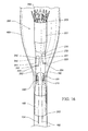
FIG. 1 depicts one example of a device for delivering and deploying an endoluminal prosthesis. -
FIG. 2 depicts a distal portion of one example of a device for delivering and deploying an endoluminal prosthesis, including one example of a prosthesis with a precannulated fenestration. -
FIG. 3 depicts a proximal portion of one example of a device for delivering and deploying an endoluminal prosthesis, including one example of a prosthesis with a precannulated fenestration. -
FIG. 4 is a cross-sectional view of a distal portion of one example of a pusher comprising auxiliary catheters and a precannulating wire structure. -
FIG. 5 is a cross-sectional view of one example of a proximal attachment region for a delivery and deployment device. -
FIG. 6 is a cross-sectional view of one example of a distal attachment region for a delivery and deployment device. -
FIGS. 7-12 depict various stages of one example of a method of using a delivery and deployment device including one example of a prosthesis with precannulated fenestrations. -
FIG. 13 illustrates one example of an endoluminal prosthesis and a guide wire received in the prosthesis in one example of a preloaded configuration. -
FIG. 14 illustrates a close up view of one example of a pivotable fenestration in a concave orientation. -
FIG. 15 illustrates a close up view of one example of a pivotable fenestration in a convex orientation. -
FIG. 16 illustrates one example of an endoluminal prosthesis and a guide wire received in the prosthesis in one example of a preloaded configuration. -
FIG. 17 illustrates one example of an endoluminal prosthesis and a guide wire received in the prosthesis in one example of a preloaded configuration. -
FIG. 18 illustrates the prosthesis ofFIG. 17 deployed within an abdominal aorta of a patient. -
FIG. 19 illustrates one example of a sheath introduced over a segment of the guide wire and into a fenestration of the prosthesis shown inFIG. 18 . -
FIGS. 20-21 illustrate one example of a catheter and a wire guide introduced within the sheath shown inFIG. 19 and into a renal artery. -
FIG. 22 illustrates one example of a sheath introduced over another segment of the guide wire and into another fenestration of the prosthesis shown inFIG. 18 and one example of a catheter and a wire guide introduced within the sheath and into another renal artery. -
FIG. 23 illustrates one example of introducers advanced within the sheaths shown inFIGS. 19-22 . -
FIG. 24 illustrates the prosthesis shown inFIG. 18 with exemplary branch extension prostheses deployed in the fenestrations and branches of the prosthesis. -
FIG. 25 illustrates one example of an endoluminal prosthesis and a guide wire received in the prosthesis in one example of a preloaded configuration. -
FIG. 26 illustrates one example of a sheath introduced over a segment of the guide wire, and through each of a fenestration and two branches of the prosthesis shown inFIG. 25 . -
FIG. 27 illustrates the sheath shown inFIG. 26 retracted out of the two branches of the prosthesis shown inFIG. 25 . -
FIG. 28 illustrates the prosthesis ofFIG. 25 with one fenestration and one branch cannulated with exemplary wire guides. -
FIG. 29 illustrates on example of a sheath introduced over another segment of the guide wire, and through each of a fenestration and two branches of the prosthesis shown inFIG. 25 . -
FIG. 30 illustrates the sheath shown inFIG. 29 retracted out of the two branches of the prosthesis shown inFIG. 25 . -
FIG. 31 illustrates the prosthesis ofFIG. 25 with two fenestrations and two branches cannulated with exemplary wire guides. - The present disclosure relates to an endoluminal prosthesis for implantation within a human or animal body for repair of damaged vessels, ducts, or other physiological pathways and systems and methods for delivering such an endoluminal prosthesis.
- Throughout the specification, when referring to any portion of an endoluminal prosthesis or a device or system for delivering an endoluminal prosthesis, the terms "proximal" and "proximally" shall denote a position, direction, or orientation that is generally toward, or in the direction of, the operator of the device or system. The terms "distal" and "distally" shall denote a position, direction, or orientation that is generally toward, or in the direction of, the patient.
- Throughout the specification, unless the context requires otherwise, the words "comprise," "include," "and have," and variations such as "comprising," "including," and "having," imply the inclusion of an item or group of items, without the exclusion of any other item or group of items.
- The term "prosthesis" means any device, object, or structure that supports, repairs, or replaces, or is configured to support, repair, or replace a body part or a function of that body part. The term prosthesis also can mean a device that enhances or adds functionality to a physiological system. The term prosthesis may include, for example and without limitation, a stent, stent graft, filter, valve, balloon, embolization coil, and the like.
- The term "stent" means any device or structure that provides or is configured to provide rigidity, expansion force, or support to a body part, for example, a diseased, damaged, or otherwise compromised body lumen. A stent may include any suitable biocompatible material, including, but not limited to fabrics, metals, plastics, and the like. Examples of suitable materials may include metals such as stainless steel and nitinol, and plastics such as polyethylene terephthalate (PET), polytetrafluoroethylene (PTFE), and polyurethane.
- A stent may be "expandable," that is, it may be capable of being expanded to a larger-dimension configuration. A stent may expand by virtue of its own resilience (i.e., self-expanding), upon the application of an external force (i.e., balloon-expandable), or by a combination of both. In one example, a stent may have one or more self-expanding portions and one or more balloon-expandable portions. An example of a suitable self-expanding stent includes Z-STENTS®, which are available from Cook Medial Incorporated, Bloomington, Indiana, USA.
- The term "graft" describes an object, device, or structure that is joined or that is capable of being joined to a body part to enhance, repair, or replace a portion or a function of that body part. Grafts that can be used to repair body vessels may include, for example, films, coatings, or sheets of material that are formed or adapted to conform to the body vessel that is being enhanced, repaired, or replaced. A stent may be attached to or associated with a graft to form a "stent graft."
- A graft material may include a biocompatible synthetic or biological material. Examples of suitable synthetic materials may include fabrics, woven and non-woven materials, and porous and non-porous sheet materials. One exemplary synthetic graft material includes a woven polyester having a twill weave and a porosity of about 350 ml/min/cm2, and is available from VASCUTEK® Ltd., Renfrewshire, Scotland, UK. Other synthetic graft materials may include biocompatible materials such as polyester, polytetrafluoroethylene (PTFE), polyurethane, and the like. Examples of suitable biological materials may include, for example, pericardial tissue and extracellular matrix materials such as SIS.
- Examples of suitable graft materials are described in
U.S. Patent Nos. 4,502,159 ,4,675,361 ,4,861,830 ,4,902,508 ,5,017,664 ,5,733,337 ,6,206,931 ,6,358,284 ,6,379,710 ,6,666,892 ,6,752,826 , and6,939,377 , inU.S. Patent Application Publication Nos. 2002/0187288 and2003/0149471 , and in International Patent Application Publication No.WO 98/22158 - The term "vessel" refers to a tube, cavity, duct, or canal in which fluid may be contained, conveyed, and/or circulated. A body vessel (as opposed to a prosthetic vessel) is a vessel that exists naturally, or is formed naturally in the body. Examples of body vessels may include, but are not limited to, blood vessels such as the aorta and the femoral artery, the esophagus, the trachea, the ureter, the bile duct, and the like. Examples of prosthetic vessels may include, but are not limited to, stents, grafts, stent grafts, venous or aortal valves, vena cava filters, and the like.
- The term "lumen" describes a space within a vessel in which fluid may be contained, conveyed, and/or circulated. The term "endoluminal" means within a lumen, and can refer to objects that are found or that can be placed within a lumen, or methods or processes that occur within a lumen. An "endoluminal prosthesis" is a prosthesis that is found or that can be placed within a lumen. Examples of endoluminal prostheses may include, but are not limited to, stents, grafts, stent grafts, venous or aortal valves, vena cava filters, and the like. An endoluminal prosthesis may be generally tubular and include one or more lumens. Examples of tubular prostheses may include, but are not limited to, straight, curved, branched, and bifurcated prostheses.
- The term "fenestration" refers to an opening provided through a surface of a prosthesis from the interior of the prosthesis to the exterior of the prosthesis. A fenestration may have any suitable geometry including, for example, circular, semicircular, oval, oblong, or any other shape.
- Described below are various different embodiments of system and method and these are all equally applicable. No described embodiment is to be taken as limiting of another embodiment, although it is to be understood that features of the different embodiments may be combined with one another.
-
FIG. 1 shows a device for delivering and deploying anendoluminal prosthesis 20 in a vessel of a patient. The device includes adelivery catheter 1 comprising an external manipulation section 3, a proximal positioning mechanism or attachment region 5, and a distal positioning mechanism or attachment region 7. The proximal and distal attachment regions 5, 7 are positioned inside the patient's body during a medical procedure, whereas the external manipulation section 3 is positioned outside the patient's body. During a procedure, the operator controls or manipulates the external manipulation section 3 to position the proximal and distal attachment regions 5, 7 and to release theprosthesis 20 into the vessel. - The delivery and deployment device includes an
endoluminal prosthesis 20 disposed at a distal end portion of thedelivery catheter 1 between the proximal and distal attachment regions 5, 7. Theprosthesis 20 may comprise atubular graft material 18, as described above. Theprosthesis 20 may additionally or alternatively comprise one or moreexpandable stents 19 disposed at least partly coextensive with thegraft material 18. Eachstent 19 may be coupled to an interior and/or an exterior surface of thegraft material 18. Theprosthesis 20 shown inFIG. 1 comprises agraft material 18 and a plurality ofexpandable stents 19 disposed coextensive with thegraft material 18. In addition, theprosthesis 20 shown inFIG. 1 includes astent 21 extending from the distal end of thegraft material 18 so that it is at least partially uncovered from thegraft material 18. Thebare stent 21 expands and engages the body lumen, thereby anchoring theprosthesis 20 and preventing the prosthesis from moving after implantation. Thestent 21 may comprise anchoring means such as, for example, barbs (not shown) that are configured to grasp the walls of the body lumen. - The
prosthesis 20 shown inFIG. 1 further comprises afenestration 27 disposed in the graft material between proximal and distal end openings of thetubular graft 18. Thefenestration 27 provides a fluid pathway through the side wall of the graft tube and allows theprosthesis 20 to be placed in a main vessel in overlapping relationship with an intersecting branch vessel, without interrupting flow to the branch vessel. - The
prosthesis 20 is disposed at a distal end portion of thedelivery catheter 1. Theprosthesis 20 is retained over thedelivery catheter 1 by anelongate sheath 30. Thesheath 30 comprises an elongate tubular body having an axial lumen (not shown). Thesheath 30 extends proximally to the manipulation region 3. Theprosthesis 20 is disposed within an axial lumen of thesheath 30 in a radially-compressed configuration. InFIG. 1 , theprosthesis 20 is depicted in a partially deployed state, whereby thesheath 30 is partially retracted over the prosthesis, exposing the prosthesis and allowing it to radially expand. - The
sheath 30 preferably comprises a flexible structure that is able to bend and flex to negotiate complex and tortuous inner body lumina. Thesheath 30 may comprise a biocompatible plastic such as PTFE, polyethylene, nylon, or the like. Examples of suitable sheath devices and materials are disclosed inU.S. Patent Nos. 5,380,304 ,6,589,227 , and7,025,758 , and inU.S. Patent Application Publication Nos. 2001/0034514 ,2002/0032408 and2006/01555302 - The delivery catheter shown in
FIG. 1 further comprises aninner cannula 15 that extends distally from the manipulation region 3 to the distal attachment region 7. Theinner cannula 15 has an axial lumen that is configured to receive aguide wire 13. Theinner cannula 15 extends distally from a proximal end portion of thedelivery catheter 1 to a distal end portion of the catheter. A taperedextension 11 is coupled to the distal end of thecannula 15 and forms the distal end of thedelivery catheter 1. Connection means 16 is coupled to the proximal end of thecannula 15. Connection means 16 is adapted to accept a syringe and may be used to introduce reagents into the body lumen. - The
cannula 15 is slidingly disposed within the lumen of thesheath 30. Theprosthesis 20 is retained over a distal portion of thecannula 15 by thesheath 30. Thecannula 15 is preferably flexible so that the device can be advanced within a relatively tortuous vessel, such as a femoral artery or the aortic arch. Thecannula 15 may comprise metal, for example aluminum, stainless steel, or nitinol. Thecannula 15 is in mechanical communication with theflexible extension 11. This allows the operator to control theflexible extension 11 remotely during a procedure. For example, the operator can rotate or slide theflexible extension 11 relative to theprosthesis 20 by manipulating thecannula 15. - The
delivery catheter 1 shown inFIG. 1 further comprises an elongatetubular pusher 28 that extends distally from the manipulation region 3 to the proximal attachment region 5. Thecannula 15 is slidably disposed within an axial lumen (not shown) of thepusher 28. Thesheath 30 is slidably disposed over a distal end portion of thepusher 28. Thepusher 28 may comprise any suitable biocompatible material including metal or plastic. Thepusher 28 may comprise a radiopaque material. Suitable materials include, but are not limited to aluminum, nitinol, nylon, polypropylene, and polyethylene. Thepusher 28 preferably has high longitudinal column strength to ensure adequate energy transfer between the user and the prosthesis during deployment. - The delivery and deployment device further comprises a haemostatic sealing means 35 for controlling blood loss through the delivery and deployment device. The sealing means 35 is fixedly connected to the
sheath 30 and couples the sheath and thepusher 28. The sealing means 35 comprises one or more haemostatic valves (not shown) that provide a haemostatic seal between thesheath 30 and thepusher 28. Suitable haemostatic valves include, for example, disk valves, iris valves, and the like. The haemostatic sealing means 35 also may include aside tube 36 that facilitates the introduction of medical reagents between thepusher 28 and thesheath 30.U.S. Patent Nos. 6,416,499 and7,651,519 , andU.S. Patent Application Publication Nos. 2005/0171479 and2007/0078395 describe examples of suitable haemostatic sealing devices that can be used with a delivery catheter described in the present disclosure. Each of these patent references is incorporated by reference herein in its entirety. - The distal end of the
pusher 28 is disposed adjacent the proximal end of theprosthesis 20. To deploy theprosthesis 20, the operator slides thesheath 30 proximally while applying distal pressure to thepusher 28 in the user manipulation region 3. The pusher prevents theprosthesis 20 from sliding proximally with thesheath 30 when the sheath is withdrawn. As a result, thesheath 30 retracts proximally over theprosthesis 20, exposing the prosthesis, thereby allowing it to expand radially outwardly. - The proximal end of the
pusher 28 is connected to anauxiliary access device 38. Theaccess device 38 comprises ahousing 40, a channel 42 extending generally axially through the housing, and a port 44 coupled to the channel 42. The port 44 provides fluid and mechanical communication between the user manipulation section 3 and the channel 42, which provides fluid and mechanical communication with anaxial lumen 33 of thepusher 28 which, in turn, provides fluid and mechanical communication with theprosthesis 20. -
FIG. 3 depicts anexemplary access device 38 withmultiple channels multiple ports ports pusher 28. Alternatively or additionally, theports pusher 28. - The
access device 38 preferably includes one or more haemostatic valves (not shown), as described above, to control blood loss during a procedure. For example, one ormore ports access device 38. -
FIGS. 1-4 depict delivery and deployment devices comprising aprosthesis 20 with at least oneprecannulated fenestration 27. The devices comprise awire 31 having afirst end 31 A, asecond end 31 B, and a body portion orintermediate segment 31C disposed between the ends. Thewire 31 may be formed from any suitable material, such as a biocompatible metal or plastic, and with dimensions suitable for the particular application. In one example, a wire comprises a highly elastic metal, such as nitinol or the like, and has a diameter in the range of about 0.016 to about 0.018 inches. Wires made of other materials, and having other diameters are also contemplated. Although thedelivery catheter 1 is described in connection with delivery of theprosthesis 20 with thewire 31 preloaded therein, the delivery catheter is equally suitable for use with other prostheses (e.g., theprosthesis 100 and/or the prosthesis 200) and wires in other configurations (e.g., theguide wire 150 preloaded in theprostheses 100 as shown inFIG. 13 or theguide wire 150 preloaded in theprosthesis 200 as shown inFIGS. 16-17 or 25). - The
wire 31 traverses thedelivery catheter 1 between proximal and distal end portions of the catheter. Each wire end 31A, 31 B is disposed at the external manipulation section 3 of thedelivery catheter 1 and can be directly manipulated by the operator during a procedure. Thewire 31 extends distally from thefirst end 31A through theport 44A, through the axial lumen 33 (shown, for example, inFIG. 3 ) of the delivery catheter, into the lumen of the prosthesis 20 (shown, for example, inFIG. 2 ), and through thefenestration FIGS. 1 and2 ). Thewire 31 then extends proximally through the lumen of theprosthesis 20, through the axial lumen 33 (shown, for example, inFIG. 3 ), and through theport 44B toward thesecond wire end 31 B. - In some examples, the
lumen 33 may comprise a single lumen structure, and thewire 31 will extend proximally and distally along the delivery catheter through the single lumen structure. In other examples, thelumen 33 may comprise a multi-lumen structure, and thewire 31 will extend proximally and distally along the delivery catheter through separate lumen structures. - The
wire 31 is slidably disposed within thefenestration wire 31 proximally through thefenestration first wire end 31A or by pushing distally on thesecond wire end 31 B. Similarly, the operator can move thewire 31 distally through thefenestration second wire end 31 B or by pushing distally on thefirst wire end 31A. This feature provides the operator with control over the positioning and configuration of thewire 31 with respect to thefenestration wire 31 as it passes through thefenestration first wire end 31A and manipulating thesecond wire end 31 B, or vice versa. Other advantages of this feature will be apparent to one of ordinary skill in the art. -
FIG. 2 depicts aprosthesis 20 with multiple (more than one) precannulated fenestrations 27A, 27B. Thewire 31 extends distally from thefirst wire end 31A through theaxial lumen 33 of the delivery catheter, into the lumen of theprosthesis 20, and through thefenestration 27A to the exterior of thegraft 18. Thewire 31 extends proximally from the exterior of thegraft 18 through thefenestration 27B into the lumen of theprosthesis 20, and through theaxial lumen 33 toward thesecond wire end 31 B. As shown inFIG. 2 , one or more stabilizingsutures prosthesis 20 to attach thewire 31 to the graft material and/or to the stent structure. Thesutures fenestrations - As shown in
FIG. 2 , thewire 31 may pass through the lumen of theprosthesis 20 as it traverses thefenestrations wire 31 extending between thefenestrations graft 18. In some examples, the wire extends approximately 3 cm or more away from a fenestration and then passes through the graft material into the lumen of the prosthesis. In other examples, the wire extends approximately 6 cm or less away from a fenestration and then passes through the graft material into the lumen of the prosthesis. In other examples, thewire 31 traverses thefenestrations prosthesis 20. In other words, thewire 31 traverses thefenestrations graft 18. Thewire 31 may at least partially circumferentially traverse the exterior surface of thegraft 18 between thefenestrations wire 31 may be positioned such that no portion of the wire extends distally beyond the distal end of theprosthesis 20. - As shown in
FIGS. 2-4 ,auxiliary catheters prosthesis 20 through theauxiliary access device 38. Theauxiliary catheters elongate sheath elongate dilator sheath auxiliary catheters catheters side tubes 58A, 58B for introducing medical reagents through the auxiliary catheters. Thedilators auxiliary catheters lumen 33 of thepusher 28, as described above. - The
auxiliary catheters prosthesis 20. For example, as described in greater detail below, theauxiliary catheters fenestrations - As shown in
FIGS. 1 ,5 , and6 , a device for delivering and deploying a prosthesis may optionally comprise one or more retention devices for retaining at least a portion of the prosthesis. For example, adelivery catheter 1 may comprise a proximalprosthesis retention device 70 for retaining a proximal end of theprosthesis 20 and a distalprosthesis retention device 80 for retaining a distal end of the prosthesis.FIGS. 1 and5 depict an exemplary proximalprosthesis retention device 70 comprising aproximal trigger wire 72. Thetrigger wire 72 extends between theprosthesis 20 and the external manipulation section 3 through anaxial lumen 33 of thepusher 28. Thetrigger wire 72 preferably is disposed in an axial lumen separate from thecannulating wire 31 to prevent entanglement between the wires. A proximal end of thewire 72 is connected to control member 74 (FIG. 1 ). A distal end of thewire 72 is removably connected to the proximal end of the prosthesis 20 (FIG. 5 ) and limits axial displacement of the prosthesis. Thetrigger wire 72 can be disconnected from the proximal end of theprosthesis 20 by manipulating thecontrol member 74, for example by sliding the control member proximally to pull the wire away from the prosthesis. Clamping screw 75 may be provided to clamp thecontrol member 74 to prevent inadvertent disengagement of thetrigger wire 72. -
FIGS. 1 and6 depict an exemplary distalprosthesis retention device 80 comprising adistal trigger wire 82 and atop cap 86. Thecap 86 is fixedly coupled to theinner cannula 15 and holds the distal end of theprosthesis 20 in a radially constrained configuration. Thecap 86 prevents the distal end of theprosthesis 20 from expanding during use. Thetrigger wire 82 extends between theprosthesis 20 and the external manipulation section 3 through anaxial lumen 33 of thepusher 28. Thetrigger wire 82 preferably is disposed in an axial lumen separate from thecannulating wire 31 to prevent entanglement of the wires. A proximal end of thewire 82 is connected to the control member 84 (FIG. 1 ). A distal end of thewire 82 is removably connected to the distal end of theprosthesis 20 and to thecap 86. Thetrigger wire 82 can be disconnected from theprosthesis 20 and thecap 86 by manipulating thecontrol member 84, for example, by sliding the control member proximally to pull the wire away from the prosthesis and the cap. A clamping screw 85 may be provided to clamp thecontrol member 84 to prevent inadvertent disengagement of thetrigger wire 82. Once thewire 82 disengages theprosthesis 20 and thecap 86, the cap can be removed from the prosthesis by sliding theinner cannula 15 distally with respect to thepusher 28. - Various devices and systems for retaining proximal, distal, and medial portions of a prosthesis are disclosed in the patent literature. For example,
U.S. Patent Nos. 6,524,335 ,7,335,224 ,7,435,253 ,7,537,606 ,7,611,529 ,7,651,519 , and7,722,657 , andU.S. Patent Application Publication Nos. 2004/230287 ,2006/0004433 ,2007/0043425 , and2008/0294234 disclose devices and systems that are suitable for use with the present invention. Each of these patent references is incorporated herein by reference in its entirety. -
FIGS. 7-12 depict various stages of a method for delivering and deploying a prosthesis comprising a precannulated fenestration into the aorta. Although the method is described in relation to a device for treating the aorta, it can readily be applied to other devices and indications. - A
delivery catheter 1, as described, for example with respect toFIG. 1 , is provided and comprises apusher 28 and aninner cannula 15 slidingly disposed within an axial lumen of the pusher. Thedelivery catheter 1 is slidingly disposed within an axial lumen of thesheath 30. Theprosthesis 20 is disposed over a distal end portion of thedelivery catheter 1 within the axial lumen ofsheath 30. Atop cap 86 retains a distal end portion of theprosthesis 20 to prevent premature radial expansion of the distal end of the prosthesis as thesheath 30 is retracted proximally over thedelivery catheter 1. Although not shown inFIGS. 7-12 , theprosthesis 20 may comprise one or more expandable stents, as described above. -
FIG. 7 depicts the delivery and deployment device disposed in an undeployed configuration within a vessel 90 (such as the aorta). The device comprises aprosthesis 20 withmultiple fenestrations prosthesis 20 and thebranch vessels prosthesis 20 can be placed within thevessel 90 so that it overlaps thebranch vessels wire 31 is provided having afirst end 31 A, asecond end 31 B, and awire body 31C. Thewire 31 extends distally from thefirst wire end 31 A through theaxial lumen 33 of the delivery catheter, into the lumen of theprosthesis 20, and through thefenestration 27A to the exterior of thegraft 18. Thewire 31 extends proximally from the exterior of thegraft 18 through thefenestration 27B into the lumen of theprosthesis 20, and through theaxial lumen 33 toward thesecond wire end 31 B. - The
delivery catheter 1 may be delivered within thevessel 90 in a conventional manner. A guide wire (not shown) is introduced, for example, into a femoral artery and advanced into the vessel until the tip of the guide wire extends beyond the region in which theprosthesis 20 will be placed. The delivery and deployment device is then inserted over theguide wire 13, via theinner cannula 15, into thevessel 90 and positioned by radiographic techniques generally known in the art. Provision may be made for a separate angiographic catheter (not shown) at the level of the branch vessels 92. - At this stage, the
prosthesis 20 is disposed in a compressed configuration within thetop cap 86 and an axial lumen of thesheath 30. Anauxiliary catheter 50A may be provided and inserted over thefirst wire end 31A and through theport 44A into an axial lumen of thedelivery catheter 1. Likewise, anauxiliary catheter 50B may be provided and inserted over thesecond wire end 31 B and throughport 44B into an axial lumen of thedelivery catheter 1. - The delivery and deployment device is positioned within the vessel by radiographic means so that the
prosthesis 20 overlaps the ostia of, andfenestrations branch vessels sheath 30 is retracted to expose theprosthesis 20. This action releases the prosthesis so that it can expand radially toward the vessel walls, as shown inFIG. 8 . Thetop cap 86 retains the distal end of theprosthesis 20, however, and prevents it from expanding at this stage. The operator may release the distal end of theprosthesis 20 at a desired stage by sliding thetop cap 86 distally with respect to the prosthesis. - In
FIG. 9 , theauxiliary catheter 50A is advanced distally over thewire 31 within the lumen of theprosthesis 20 until the distal end of thesheath 54A passes through thefenestration 27A. Similarly, theauxiliary catheter 50B is advanced distally over thewire 31 within the lumen of theprosthesis 20 until the distal end of thesheath 54B passes through thefenestration 27B. InFIG. 10 , thedilators auxiliary catheters sheaths - Next,
branch guide wires FIG. 11 , thebranch guide wire 94A is delivered through thesheath 54A alongside a first end portion of thewire 31, and thebranch guide wire 94B is delivered through thesheath 54B alongside a second end portion of thewire 31.Branch access catheters guide wires access catheters branch wires fenestrations respective branch vessels - Once the branch vessels are cannulated, the
catheters sheaths preloaded wire 31 is no longer needed and may be removed by pulling proximally on thefirst wire end 31 A until thesecond wire end 31 B exits theport 44A, or by pulling on the second wire end until the first wire end exits theport 44B. - With the
guide wires interventional catheters branch vessels fenestrations FIG. 12 . -
FIG. 13 illustrates one example of aprosthesis 100. Theprosthesis 100 may be configured as a stent graft. To that end, theprosthesis 100 may include atubular body 101 of a biocompatible graft material. Thetubular body 101 may be configured as a tubular main graft body of theprosthesis 100. The biocompatible graft material may form a sidewall of thetubular body 101. Theprosthesis 100 may have aproximal end 102 and adistal end 103. Thetubular body 101 may include a proximal end opening at theproximal end 102 and a distal end opening at thedistal end 103. Alumen 104 may extend generally longitudinally within theprosthesis 100. Thelumen 104 may extend from the proximal end opening to the distal end opening to permit passage of blood or other body fluid through the tubular body from the distal end to the proximal end. - An anterior side of the
prosthesis 100 may extend circumferentially around approximately half of the circumference of thetubular body 101 of the prosthesis. A posterior side of theprosthesis 100 may extend circumferentially around approximately the other half of the circumference of thetubular body 101. The posterior side of theprosthesis 100 may be positioned opposite the anterior side with respect to the circumference of the prosthesis. In other words, a plane may be defined to include the longitudinal axis of theprosthesis 100. The anterior side of theprosthesis 100 may be positioned on one side of the plane, and the posterior side of the prosthesis may be positioned on the opposite side of the plane from the anterior side. The anterior side and the posterior side may cooperatively form thetubular body 101 of theprosthesis 100. - The
prosthesis 100 may include one or more stents 105 (seeFIG. 14 ) coupled to the graft material of thetubular body 101. Thestents 105 may be conventional stents having any configuration known in the art. Thestents 105 may be self-expanding or balloon expandable. Preferably, thestents 105 are self-expanding. Thestents 105 may be coupled to an internal surface of the graft material and/or an external surface of the graft material. Theprosthesis 100 may include an attachment mechanism such as anattachment stent 106 at either or both ends of the prosthesis. The attachment mechanism may aid in securing theprosthesis 100 within the body vessel to prevent migration of the prosthesis within the body vessel. - The
prosthesis 100 may include one or more fenestrations or openings formed through the graft material of the prosthesis. For example, theprosthesis 100 may include one or more fenestrations formed in the sidewall of thetubular body 101. Any of the fenestrations described herein may be configured as any type of opening providing a fluid pathway through the graft material between thelumen 104 of theprosthesis 100 and a point external to the prosthesis. Additionally, or alternatively, any of the fenestrations described herein may be configured to receive a branch extension prosthesis to couple theprosthesis 100 to a branch vessel as further described below. Additionally, or alternatively, any of the fenestrations described herein may be in fluid communication with a branch extending from thetubular body 101 of theprosthesis 100 as further described below. Additionally, or alternatively, any of the fenestrations described herein may be pivotable or non-pivotable. - In one example, the
prosthesis 100 may include afirst fenestration 110, asecond fenestration 120, athird fenestration 130, and ascallop 140 as shown inFIG. 13 . The first andsecond fenestrations third fenestration 130 may be non-pivotable. Although theprosthesis 100 is generally described as including twopivotable fenestrations non-pivotable fenestration 130, the disclosure is not so limited. In other examples, any of the fenestrations may be pivotable or non-pivotable, and such examples are within the scope of this disclosure. The first andsecond fenestrations prosthesis 100 to align with, for example, the renal arteries. It will be recognized by one of ordinary skill in the art that theprosthesis 100 may include any number of openings of any type. Also, the openings may be arranged on the prosthesis in any manner. Preferably, the openings may be arranged to correspond to a particular position within the anatomy into which the prosthesis is intended to be placed. - The
prosthesis 100 illustrated inFIG. 13 may be configured for placement in an abdominal aorta of a patient. Theprosthesis 100 may be configured to extend between a point proximal of the renal arteries and a point distal of the renal arteries. To that end, thescallop 140 may be configured to align with the celiac artery, thethird fenestration 130 may be configured to align with the superior mesenteric artery, and the first andsecond fenestrations scallop 140 may be positioned circumferentially on an anterior point of theprosthesis 100 and longitudinally near thedistal end 103 of the prosthesis. The anterior point of theprosthesis 100 may extend generally longitudinally along thetubular body 101 of the prosthesis and may be substantially circumferentially centered on the anterior side of the prosthesis. Thethird fenestration 130 may be positioned circumferentially on the anterior point of theprosthesis 100 and longitudinally proximal of thescallop 140. The first andsecond fenestrations prosthesis 100. For example thefirst fenestration 110 may be configured to align with the right renal artery and may be spaced a first circumferential distance from the anterior point of theprosthesis 100. Thesecond fenestration 120 may be configured to align with the left renal artery and may be spaced a second circumferential distance from the anterior point of theprosthesis 100. The first and second circumferential distances may be of substantially equal lengths in opposite directions relative to the anterior point of theprosthesis 100. Alternatively, the first and second circumferential distances may be different from one another, for example, to correspond to the anatomy of a particular patient. The first andsecond fenestrations tubular body 101 of theprosthesis 100. Alternatively, the first andsecond fenestrations second fenestrations third fenestration 130 and thescallop 140. - The
lumen 104 of theprosthesis 100 may be in fluid communication with a point external to the prosthesis through each of the first andsecond fenestrations second fenestrations prosthesis 100 to a branch vessel within the body of the patient. For example, thefirst fenestration 110 may be configured to receive a branch extension prosthesis to couple theprosthesis 100 to the left renal artery, and thesecond fenestration 120 may be configured to receive a branch extension prosthesis to couple the prosthesis to the right renal artery as further described below. In one example, the first and/orsecond fenestrations U.S. Patent Application Publication No. 2012/0046728 , which is incorporated by reference herein in its entirety. To that end, each of the first andsecond fenestrations tubular body 101 of theprosthesis 100 to account for any misalignment between the fenestration and the corresponding branch vessel. -
FIG. 14 shows a close-up view of thesecond fenestration 120, which may be configured as a pivotable fenestration. In this example, thesecond fenestration 120 may include aninner perimeter 122 surrounding thefenestration 120, aband 124 surrounding theinner perimeter 122, and anouter perimeter 126 surrounding theband 124. Theouter perimeter 126 may have a diameter that is greater than a diameter of theinner perimeter 122. Theinner perimeter 122, theband 124, and theouter perimeter 126 may be substantially concentric with one another if brought into the same plane, for example, the surface plane of thetubular body 101. The band may have a first diameter that is substantially the same as the diameter of theinner perimeter 122 and a second diameter that is substantially the same as the diameter of theouter perimeter 126. The diameter of the band may decrease in a direction away from the exterior surface of thetubular body 101 from theouter perimeter 126 to theinner perimeter 122. In this manner, theinner perimeter 122, theband 124, and theouter perimeter 126 may form an extension having a protruding shape, resembling a dome, or a frustoconical cone extending from the surface of thetubular body 101. Thesecond fenestration 120 may be positioned at the peak or top of the extension. The pivotable fenestration may be placed in a concave orientation or a convex orientation. In the concave orientation, the extension may extend into thelumen 104 of theprosthesis 100 as shown inFIGS. 13-14 . In the convex orientation, the extension may extend away from thelumen 104 as shown inFIG. 15 . The pivotable fenestration may be movable between the concave orientation and the convex orientation. Additionally, or alternatively, the pivotable fenestration may be placed in any position between the concave orientation and the convex orientation. For example, theband 124 may be folded, bent, gathered, pleated, or otherwise manipulated such that thesecond fenestration 120 is generally aligned with the surface plane of theprosthesis 100. - The
outer perimeter 126 may be affixed to the graft material of thetubular body 101 by any attachment method including suturing circumferentially about an aperture disposed through the graft material. Theband 124 may be sufficiently flexible to permit thesecond fenestration 120 to move such that a branch prosthesis disposed in the fenestration may be oriented upwardly, downwardly, laterally, diagonally, and the like relative to the surface of thetubular body 101 of theprosthesis 100. In some examples, theband 124 may permit thesecond fenestration 120 to move up to about 180 degrees relative to the surface plane of theprosthesis 100. Accordingly, the pivotable fenestration may enable theprosthesis 100 to be used in a variety of patients due to its ability to adapt to the variance in the positioning of the diseased branch vessels. For example, if a branch vessel is or becomes offset longitudinally or axially from the pivotable fenestration, the pivotable fenestration may pivot the branch prosthesis in the necessary direction and to the necessary degree to maintain the branch prosthesis in place in the branch vessel. - The
first fenestration 110 may be configured as a pivotable fenestration as shown inFIG. 15 . To that end, thefirst fenestration 110 may include aninner perimeter 112 surrounding thefenestration 110, aband 114 surrounding theinner perimeter 112, and anouter perimeter 116 surrounding theband 114. In this example, thefirst fenestration 110 may be configured generally as described above with reference to thesecond fenestration 120. - As shown throughout
FIGS. 14-15 ,imageable markers 128 may be placed at various positions on theprosthesis 100 to identify certain aspects of the prosthesis and locations of those aspects during implantation of the prosthesis within the vasculature of a patient. Themarkers 128 may be viewed during and after placement of theprosthesis 100 to facilitate correct placement of the first, second, and/orthird fenestrations scallop 140, theends FIG. 14 ,markers 128 may be placed about the circumference of theouter perimeter 126 of the pivotable fenestration. Themarkers 128 may be, for example, sewn or sutured to the graft material of thetubular body 101 or woven into the graft material. Additionally, or alternatively, themarkers 128 may be placed on the struts of one ormore stents 105. For example, radiopaque marker tubes may be placed about one or more struts of any of the stents. Themarkers 128 may be formed from any material that may be imaged by way of fluoroscopy, 3D imaging, MRI, or the like. For example, one suitable material may be gold. - The
prosthesis 100 may be sized and shaped for placement within the vasculature of a patient as further described below. The preferred size and shape of theprosthesis 100 may depend on the anatomy in which it is to be implanted. Physiological variables, deployment characteristics, and other factors also may contribute to the determination of a proper size and shape of theprosthesis 100. For example, theprosthesis 100 may have a size and shape suitable for placement in the abdominal aorta. To that end, thetubular body 101 of theprosthesis 100 may have a diameter, for example, ranging from about 10 mm to about 38 mm, typically from about 19 mm to about 31 mm. The diameter of thetubular body 101 may be generally constant along the length thereof. Alternatively, thetubular body 101 may be tapered such that the diameter of the tubular body may generally increase or decrease along the length thereof. The first andsecond fenestrations second fenestrations prosthesis 100 may be deployed in combination with various other prostheses to effectively bridge an aneurysmal portion of the vasculature. - The tubular body and the bands of the pivotable fenestrations may be made of any material known in the art. The tubular body may be made of the same or a different material as the bands of the pivotable fenestrations. Preferably, the tubular body and the bands may be formed from a biocompatible material that is substantially non-toxic in the in vivo environment of its intended use and substantially unrejected by the patient's physiological system (i.e., is non-antigenic). For example, the tubular body and/or the bands of the pivotable fenestrations may be made of an expanded polytetrafluoroethylene (ePTFE), polytetrafluoroethylene (PTFE), silicone, polyurethane, polyamide (nylon), polyethylene, polypropylene, polyaramids, polyacrylonitrile, cellulose, or another flexible biocompatible material. Additionally, or alternatively, the tubular body and/or the bands of the pivotable fenestrations may be made of known fabric graft materials, e.g., woven polyester such as DACRON® from Invista, Wichita, Kansas, USA, polyetherurethanes such as THORALON® from Thoratec Corporation, Pleasanton, California, USA, or polyethylene such as an ultra-high molecular weight polyethylene (UHMwPE) such as DYNEEMA® from DSM Dyneema LLC, Stanley, North Carolina, USA. In addition, materials that are not inherently biocompatible may be subjected to surface modifications to render the materials biocompatible. Examples of surface modifications include, for example, graft polymerization of biocompatible polymers on the surface, coating of the surface with a crosslinked biocompatible polymer, chemical modification with biocompatible functional groups, or immobilization of a compatibilizing agent such as heparin or other biocompatible substances. Thus, any fibrous material having sufficient strength to survive in the in vivo environment may be used to form a textile graft, provided the final textile is biocompatible.
- The tubular body and/or the bands of the pivotable fenestrations may include a bioremodelable material such as reconstituted or naturally-derived collagenous materials. Suitable remodelable materials may be provided by collagenous extracellular matrix (ECM) materials possessing biotropic properties. For example, suitable collagenous materials may include ECM materials such as those comprising submucosa, renal capsule membrane, dermal collagen, dura mater, pericardium, fascia lata, serosa, peritoneum or basement membrane layers, including liver basement membrane. Suitable submucosa materials for these purposes may include, for instance, intestinal submucosa including small intestinal submucosa, stomach submucosa, urinary bladder submucosa, and uterine submucosa. Collagenous matrices including submucosa (potentially along with other associated tissues) useful in the present invention can be obtained by harvesting such tissue sources and delaminating the submucosa-containing matrix from smooth muscle layers, mucosal layers, and/or other layers occurring in the tissue source. For additional information as to some of the materials useful in the present invention, and their isolation and treatment, reference can be made, for example, to
U.S. Patent Nos. 4,902,508 ,5,554,389 ,5,993,844 ,6,206,931 , and6,099,567 . Non-limiting examples of suitable remodelable materials may include SURGISISO BIODESIGN™ from Cook Medical Incorporated, Bloomington, Indiana, USA or the graft prosthesis material described inU.S. Patent No. 6,206,931 to Cook et al. , which is incorporated herein by reference in its entirety. The graft bodies also may be made of any of the materials described inU.S. Patent No. 7,407,509 to Greenberg et al. orU.S. Patent Application Publication No. 2009/0171451 by Kuppurathanam et al. , which are incorporated herein by reference in their entirety. - The stents described herein may have any suitable stent pattern known in the art. One example of a stent pattern is the Z-stent or Gianturco stent design. Each Z-stent may include a series of substantially straight segments or struts interconnected by a series of bent segments or bends. The bent segments may include acute bends or apices. The Z-stents are arranged in a zigzag configuration in which the straight segments are set at angles relative to one another and are connected by the bent segments. This design provides both significant radial force as well as longitudinal support. In tortuous anatomy, branches, or fenestrations, it may be preferable to use alternative stents or modifications to the Z-stent design to avoid stent-to-stent contact. Alternative stents may include, for example, annular or helical stents. Furthermore, in complex anatomical situations, external stents may have the potential to become intertwined with the wires or other devices utilized to ensure branch vessel access, sealing, and fixation. Thus, in some instances, it may be desirable to affix some of the stents to the internal surface of the prosthesis. The stents may be balloon expandable. Preferably, the stents may be self-expandable. The stents can maintain the patency of the prosthesis and ensure adequate sealing against the surrounding vascular tissue. Stent amplitude, spacing, and stagger may be adjusted for each prosthesis design. Any of the stents mentioned herein may include barbs and/or other anchoring members to help reduce the potential for prosthesis migration.
- The stents described herein may be made from any suitable material known in the art. In one example, the stents may be made from standard medical grade stainless steel and soldered using silver standard solder (0 lead/0 tin). In other examples, the stents may be made from a metallic material including any type of stainless steel, silver, platinum, palladium, gold, titanium, tantalum, iridium, tungsten, cobalt, chromium, cobalt-chromium alloy 1058, cobalt-based 35N alloy, nickel-based alloy 625, a molybdenum alloy, a molybdenum alloy including about 0.4% to about 0.8% of lanthanum oxide (La2O3), and a nickel-titanium alloy, or other suitable materials known in the art. Additionally, or alternatively, the stents may be made from nitinol or other shape-memory metal. Moreover, the stents may be configured in a variety of ways to provide a suitable intraluminal support structure. For example, one or more stents may be made from a woven wire structure, a laser-cut cannula, individual interconnected rings, or another pattern or design.
- Returning to
FIG. 13 , theprosthesis 100 may be provided as part of a preloaded system that includes aguide wire 150. Theguide wire 150 may enable delivery of one or more branch extension prostheses as further described below. In some examples, a single guide wire may enable delivery of a branch extension prosthesis into multiple openings in the prosthesis. -
FIG. 13 illustrates one example of theguide wire 150 received within theprosthesis 100 in a preloaded configuration. Theguide wire 150 may include afirst end segment 152 positioned at a first end of the guide wire and asecond end segment 154 positioned at a second end of the guide wire opposite the first end. Theguide wire 150 also may include a body portion orintermediate segment 156 positioned between thefirst end segment 152 and thesecond end segment 154. Thefirst end segment 152 of theguide wire 150 may extend distally from a proximal end of a delivery device (e.g., thedelivery catheter 1 described above). Thefirst end segment 152 may enter thelumen 104 through theproximal end 102 of theprosthesis 100. Thefirst end segment 152 may extend distally within thelumen 104 and exit thetubular body 101 of theprosthesis 100 through thefirst fenestration 110. - The
intermediate segment 156 of theguide wire 150 may extend distally from thefirst end segment 152 and external of thetubular body 101 of theprosthesis 100. Theintermediate segment 156 may reenter thetubular body 101 of theprosthesis 100 through a firstguide wire opening 160. The firstguide wire opening 160 may be configured as an opening through the graft material of thetubular body 101. The firstguide wire opening 160 may be aligned with thefirst fenestration 110 with respect to the circumference of theprosthesis 100 and positioned distal of thethird fenestration 130 with respect to the longitudinal axis of the prosthesis as shown inFIG. 13 . In other examples, the firstguide wire opening 160 may be positioned at any suitable location on thetubular body 101 of theprosthesis 100. Thelumen 104 of theprosthesis 100 may be in fluid communication with a point external of the prosthesis through the firstguide wire opening 160. - A portion of the
intermediate segment 156 of theguide wire 150 may be disposed within thelumen 104 of theprosthesis 100 and extend between the firstguide wire opening 160 and a secondguide wire opening 162. The secondguide wire opening 162 may be configured generally as described above with respect to the firstguide wire opening 160. The secondguide wire opening 162 may be aligned with thesecond fenestration 120 with respect to the circumference of theprosthesis 100 and positioned distal of thethird fenestration 130 with respect to the longitudinal axis of the prosthesis. The portion of theintermediate segment 156 positioned between the firstguide wire opening 160 and the secondguide wire opening 162 may be substantially U-shaped. The opening of the U-shaped portion of theintermediate segment 156 may face proximally as shown inFIG. 13 . One leg of the U-shaped portion of theintermediate segment 156 may extend distally from the firstguide wire opening 160, and the other leg may extend proximally to the secondguide wire opening 162. The curved portion of the U-shaped portion of theintermediate segment 156 between the two legs may be positioned distal of thethird fenestration 130 with respect to the longitudinal axis of theprosthesis 100. In one example, the curved portion of the U-shaped portion of theintermediate segment 156 may overlap with thescallop 140 as shown inFIG. 13 . - The
intermediate segment 156 of theguide wire 150 may exit thelumen 104 of theprosthesis 100 through the secondguide wire opening 162 and extend proximally external of thetubular body 101 of theprosthesis 100. Thesecond end segment 154 of theguide wire 150 may extend proximally from theintermediate segment 156 and enter thetubular body 101 of theprosthesis 100 through thesecond fenestration 120. Thesecond end segment 154 of theguide wire 150 may extend proximally within thelumen 104 and exit thelumen 104 through theproximal end 102 of theprosthesis 100. Thesecond end segment 154 of theguide wire 150 may extend proximally to the proximal end of the delivery device. Thefirst end segment 152 of theguide wire 150 may enable introduction of a branch prosthesis into thefirst fenestration 110 to couple theprosthesis 100 to the left renal artery, and thesecond end segment 154 of theguide wire 150 may enable introduction of a branch extension prosthesis into thesecond fenestration 120 to couple the prosthesis to the right renal artery. -
FIGS. 16-17 illustrate another example of anendoluminal prosthesis 200. Theprosthesis 200 may be configured as a stent graft and may be similar to theprosthesis 100 except for the differences described below. For example, theprosthesis 200 may include atubular body 201 of a biocompatible graft material. Theprosthesis 200 may have aproximal end 202, adistal end 203, and alumen 204 extending generally longitudinally within the prosthesis to permit passage of blood or other body fluid from the distal end to the proximal end. Theprosthesis 200 may have an anterior side extending circumferentially around approximately half of the circumference of thetubular body 201 and a posterior side positioned opposite the anterior side with respect to the circumference of the prosthesis. The anterior side and the posterior side may cooperatively form thetubular body 201 of theprosthesis 200. - The
prosthesis 200 may include one or more stents (not shown) coupled to the graft material. The stents may be conventional stents having any configuration known in the art as described above with respect to thestents 105 of theprosthesis 100. Theprosthesis 200 may include an attachment mechanism such as an attachment stent at either or both ends of the prosthesis as described above with respect to theattachment mechanism 106 of theprosthesis 100. - The
prosthesis 200 may include afirst fenestration 210 and asecond fenestration 220. The first andsecond fenestrations second fenestrations prosthesis 100. Although theprosthesis 200 is generally described as including twopivotable fenestrations second fenestrations prosthesis 200 to align with, for example, the renal arteries. - The
prosthesis 200 may include athird fenestration 230, and afourth fenestration 240, as shown inFIGS. 16-17 . Each of thethird fenestration 230 and thefourth fenestration 240 may be configured as a branch. In other words, theprosthesis 200 may include afirst branch 231 extending outward from thetubular body 201 and in fluid communication with thethird fenestration 230 and asecond branch 241 extending outward from thetubular body 201 and in fluid communication with thefourth fenestration 240. Although theprosthesis 200 is generally described as having fourfenestrations branches prosthesis 200 may include any number of openings of any type. For example, the first branch and/or the second branch may be omitted. Additionally, or alternatively, the openings may be arranged on the prosthesis in any manner. Preferably, the openings may be arranged to correspond to a particular position within the anatomy into which the prosthesis is intended to be placed. - The
prosthesis 200 illustrated inFIGS. 16-17 may be configured for placement in an abdominal aorta of a patient. Additionally, or alternatively, theprosthesis 200 may be configured to extend between a point distal of the renal arteries and a point proximal of the renal arteries. To that end, thefirst branch 231 may be configured to align with the celiac artery, thesecond branch 241 may be configured to align with the superior mesenteric artery, and the first andsecond fenestrations - The
first branch 231 may include afirst end 232 adjacent to thethird fenestration 230, asecond end 233, and alumen 234 extending generally longitudinally between the first and second ends of the first branch. Thefirst end 232 of thefirst branch 231 may be attached to thetubular body 201 of theprosthesis 200 in any conventional manner. In one example, thefirst end 232 of thefirst branch 231 may be sutured to the graft material of thetubular body 201. In another example, thefirst branch 231 and thetubular body 201 may be formed as a unitary piece of graft material. Thelumen 204 of thetubular body 201 may be in fluid communication with a point external to theprosthesis 200 through thelumen 234 of thefirst branch 231. Thesecond branch 241 may include afirst end 241 adjacent to thefourth fenestration 240, asecond end 243, and alumen 244 extending generally longitudinally between the first and second ends of the second branch. Thefirst end 242 of thesecond branch 241 may be attached to thetubular body 201 as described above with reference to thefirst branch 231. Thelumen 204 of thetubular body 201 may be in fluid communication with a point external to theprosthesis 200 through thelumen 244 of thesecond branch 241. - The first ends 232, 242 of the first and
second branches tubular body 201 of theprosthesis 200. In one example, the first ends 232, 242 of the first andsecond branches second branches tubular body 201 of theprosthesis 200. Thefirst end 232 may be distal of thefirst end 242 as shown inFIGS. 16-17 , or vice versa. Alternatively, the first ends 232, 242 may be disposed in close proximity to one another along the longitudinal axis of thetubular body 201. - Each of the first and
second branches first branch 231 may be configured to receive a branch extension prosthesis to couple the first branch to the celiac artery, and thesecond branch 241 may be configured to receive a branch extension prosthesis to couple the second branch to the superior mesenteric artery, as further described below. Thefirst branch 231 and/or thesecond branch 241 may extend outward away from thetubular body 201 of theprosthesis 200. Thefirst branch 231 and/or thesecond branch 241 may extend proximally with respect to thetubular body 201 as shown inFIGS. 16-17 . In other examples, thefirst branch 231 and/or thesecond branch 241 may extend distally with respect to thetubular body 201. Alternatively, or additionally, thefirst branch 231 and/or thesecond branch 241 may extend at least partially circumferentially around thetubular body 201. In other words, thefirst branch 231 and/or thesecond branch 241 may include a helical shape. Such a helical shape may facilitate insertion of a component such as a branch extension prosthesis into thefirst branch 231 and/or thesecond branch 241. Such a helical shape also may reduce torsion imposed by blood flow at the juncture between theprosthesis 200 and the branch vessels. Various exemplary helical branches that extend from a main body of a prosthesis, which may be used in conjunction with the present embodiments, are provided inU.S. Patent No. 7,407,509 to Greenberg et al. , which is incorporated by reference herein in its entirety. - The first and
second fenestrations prosthesis 200. For example thefirst fenestration 210 may be configured to align with the left renal artery and may be spaced a first circumferential distance from the anterior point of theprosthesis 200. Thesecond fenestration 220 may be configured to align with the right renal artery and may be spaced a second circumferential distance from the anterior point of theprosthesis 200. The first and second circumferential distances may be of substantially equal lengths in opposite directions relative to the anterior point of theprosthesis 200. In another embodiment, the first and second circumferential distances may be different from one another, for example, to correspond to the anatomy of a particular patient. In one example, the first andsecond fenestrations second fenestrations tubular body 201 of theprosthesis 200. Alternatively, the first andsecond fenestrations second fenestrations first branch 231 and thesecond branch 241. - The
prosthesis 200 may be provided as part of a preloaded system that includes theguide wire 150.FIG. 16 illustrates one example of theguide wire 150 received within theprosthesis 200 in a preloaded configuration. Thefirst end segment 152 of theguide wire 150 may extend distally from the proximal end of the delivery device. Thefirst end segment 152 may enter thelumen 204 through theproximal end 202 of theprosthesis 200. Thefirst end segment 152 may extend distally within thelumen 204 and exit thetubular body 201 of theprosthesis 200 through thefirst fenestration 210. Theintermediate segment 156 of theguide wire 150 may extend distally external of thetubular body 201 and reenter thelumen 204 of theprosthesis 200 through a firstguide wire opening 260. The firstguide wire opening 260 may be configured generally as described above with reference to the firstguide wire opening 160 of theprosthesis 100. The firstguide wire opening 260 may be aligned with thefirst fenestration 210 with respect to the circumference of theprosthesis 200 and positioned proximal of the first andsecond branches FIG. 16 . In other examples, the firstguide wire opening 260 may be positioned at any suitable location on thetubular body 201 of theprosthesis 200. Thelumen 204 of theprosthesis 200 may be in fluid communication with a point external of the prosthesis through the firstguide wire opening 260. - A portion of the
intermediate segment 156 of theguide wire 150 may be disposed within thelumen 204 of theprosthesis 200 and extend between the firstguide wire opening 260 and a secondguide wire opening 262. The secondguide wire opening 262 may be configured generally as described above with reference to the firstguide wire opening 160 of theprosthesis 100. The secondguide wire opening 262 may be aligned with thesecond fenestration 220 with respect to the circumference of theprosthesis 200 and positioned proximal of the first andsecond branches - The
intermediate segment 156 of theguide wire 150 may exit thelumen 204 of theprosthesis 200 through the secondguide wire opening 262 and extend proximally external of thetubular body 201 of theprosthesis 200. Thesecond end segment 154 of theguide wire 150 may enter thetubular body 201 of theprosthesis 200 through thesecond fenestration 220. Thesecond end segment 154 of theguide wire 150 may extend proximally within thelumen 204 and exit thelumen 204 through theproximal end 202 of theprosthesis 200. Thesecond end segment 154 of theguide wire 150 may extend proximally to the proximal end of the delivery device. Thefirst end segment 152 of theguide wire 150 may enable introduction of a branch prosthesis into thefirst fenestration 210 to couple theprosthesis 200 to the left renal artery, and thesecond end segment 154 of theguide wire 150 may enable introduction of a branch extension prosthesis into thesecond fenestration 220 to couple the prosthesis to the right renal artery. Additionally, or alternatively, theguide wire 150 may be positioned such that no portion of the guide wire extends distally beyond thedistal end 203 of theprosthesis 200. - In each of the examples illustrated in
FIGS. 13 and16 , theguide wire 150 may extend through a guide wire opening (e.g., the first and secondguide wire openings prosthesis 100 or the first and secondguide wire openings guide wire 150 is removed following deployment of the prosthesis within a body vessel, the guide wire openings may remain as holes in the graft material of the prosthesis. If the holes are positioned within an aneurysmal portion 669 (or another damaged portion) of the body vessel, as shown inFIG. 16 , blood or other body fluid may leak through the holes in the graft material and into the aneurysmal portion of the body vessel. In other words, the guide wire openings in the prosthesis may lead to an endoleak into theaneurysmal portion 669 of the body vessel. Such leakage may cause further damage to the body vessel. Thus, it may be desirable to provide a prosthesis that is free of guide wire openings. In other words, it may be desirable to provide a guide wire in a preloaded configuration in which the guide wire does not extend through guide wire openings in the tubular body of the prosthesis. -
FIG. 17 illustrates another example of theguide wire 150 received within theprosthesis 200 in a preloaded configuration. In this example, theprosthesis 200 may be substantially free of guide wire openings. In other words, theprosthesis 200 may not include the first and secondguide wire openings FIG. 16 . Thefirst end segment 152 of theguide wire 150 may extend distally from the proximal end of the delivery device. Thefirst end segment 152 may enter thelumen 204 through theproximal end 202 of theprosthesis 200. Thefirst end segment 152 may extend distally within thelumen 204 and exit thetubular body 201 of theprosthesis 200 through thefirst fenestration 210. - The
intermediate segment 156 of theguide wire 150 may extend between thefirst fenestration 210 and thesecond fenestration 220 of theprosthesis 200. Theintermediate segment 156 may be disposed on the exterior surface of thetubular body 201 of theprosthesis 200. Theintermediate segment 156 may be substantially U-shaped with the opening of the U-shaped intermediate segment facing proximally as shown inFIG. 17 . One leg of the U-shapedintermediate segment 156 may extend distally from thefirst fenestration 210, and the other leg may extend proximally to thesecond fenestration 220. The curved portion of the U-shapedintermediate segment 156 may be positioned longitudinally proximal of the first andsecond branches FIG. 17 . In this manner, theintermediate segment 156 may extend at least partially circumferentially around the exterior surface of thetubular body 201 of theprosthesis 200. The curve of the U-shapedintermediate segment 156 may be positioned between the first andsecond fenestrations second branches prosthesis 200. In other words, theintermediate segment 156 of theguide wire 150 may be positioned just distal of the first andsecond fenestrations prosthesis 200 as shown inFIG. 17 . In other examples, the curved portion of the U-shapedintermediate segment 156 may be positioned longitudinally at any suitable position on thetubular body 201 of theprosthesis 200. For example, the legs of the U-shapedintermediate segment 156 may have a sufficient length such that the curved portion may be positioned distal of the first and/orsecond branches - The
second end segment 154 of theguide wire 150 may enter thetubular body 201 of theprosthesis 200 through thesecond fenestration 220. Thesecond end segment 154 may extend proximally within thelumen 204 and exit thelumen 204 through theproximal end 202 of theprosthesis 200. Thesecond end segment 154 of theguide wire 150 may extend proximally to the proximal end of the delivery device. Thefirst end segment 152 of theguide wire 150 may enable introduction of a branch prosthesis into thefirst fenestration 210 to couple theprosthesis 200 to the left renal artery, and thesecond end segment 154 of theguide wire 150 may enable introduction of a branch prosthesis into thesecond fenestration 220 to couple the prosthesis to the right renal artery. Additionally, or alternatively, theguide wire 150 may be positioned such that no portion of the guide wire extends distally beyond thedistal end 203 of theprosthesis 200. - The
intermediate segment 156 of theguide wire 150 may extend at least partially circumferentially around the anterior side of the prosthesis, the posterior side of the prosthesis, or both the anterior and posterior sides of the prosthesis. Preferably, theintermediate segment 156 of theguide wire 150 may be disposed on the anterior side of the prosthesis between the first andsecond fenestrations FIG. 17 . This configuration may reduce the length of theguide wire 150 which may be disposed on the exterior surface of thetubular body 201 of theprosthesis 200. Such a reduced length of theguide wire 150 which may be exposed outside of theprosthesis 200 may reduce the potential of catching or snagging theguide wire 150 on components of the delivery system which may be used to deploy the prosthesis within the body vessel. Such a reduced length also may enable a physician to control the diameter of the prosthesis 200 (e.g., by applying tension to the guide wire 150) as further described below. Additionally, or alternatively, this configuration may enable adjustment of the circumferential positions of the first andsecond fenestrations - The
intermediate segment 156 of theguide wire 150 may be attached to thetubular body 201 of theprosthesis 200. Theintermediate segment 156 may be attached to theprosthesis 200 using any suitable attachment mechanism. For example, theintermediate segment 156 may be releasably attached to the exterior surface of thetubular body 201 by one ormore sutures 158 as shown inFIG. 17 . Thesutures 158 may be stitched into the graft material of thetubular body 201 of theprosthesis 200, and theguide wire 150 may be received between each suture and the exterior surface of the tubular body. In this example, theguide wire 150 may be removed from theprosthesis 200 by sliding the guide wire out of engagement with thesutures 158. In another example, theintermediate segment 156 of theguide wire 150 may be stitched in and out of the graft material of thetubular body 201. In yet another example, theintermediate segment 156 may be attached to the exterior surface of theprosthesis 200 by a releasable adhesive. In another example, theintermediate segment 156 may be received within a pocket, which may be attached to the exterior surface of theprosthesis 200. The pocket may include a piece of graft material that is folded or rolled to create an interior passage to receive theintermediate segment 156. The pocket may be integral with or separate from thetubular body 201 of theprosthesis 200. Alternatively, or additionally, the pocket may include a tube or catheter, which may be attached to the exterior surface of the graft material. The pocket may be positioned radially between the graft material of thetubular body 201 and an external stent of theprosthesis 200. In other words, the pocket may be sandwiched between the graft material and the stent. Alternatively, or additionally, the stent may include an aperture configured to receive the pocket and/or theintermediate segment 156 of theguide wire 150. -
FIGS. 18-24 illustrate a method of using theprosthesis 200 ofFIG. 17 to treat a condition (e.g., an aneurysm) in the area of an abdominal aorta and/or branch vessels of a patient. In a first step, theprosthesis 200 may be provided with theguide wire 150 coupled to the prosthesis in the preloaded configuration as shown inFIG. 17 . Theprosthesis 200 may be compressed into a delivery state and delivered into anabdominal aorta 660 of a patient using any suitable deployment system or introducer (e.g., thedelivery catheter 1 described above with reference toFIGS. 1-12 ). Additionally, or alternatively, an introducer such as that described in International Patent Application Publication No.WO98/53761 prosthesis 200.WO98/53761 - Using a suitable introducer, a physician may obtain access to the
abdominal aorta 660 via a femoral cut-down with theprosthesis 200 in the compressed state. Theprosthesis 200 may be positioned within theabdominal aorta 660 in the compressed state, for example, using theradiopaque markers 128, such that the first andsecond branches celiac artery 662 and the superiormesenteric artery 664, respectively, as shown inFIG. 18 . Additionally, the first andsecond fenestrations renal artery 666 and the rightrenal artery 668, respectively, as shown inFIG. 18 . At this time, the sheath of the introducer that constrains theprosthesis 200 may be retracted proximally relative to the delivery catheter to enable the prosthesis to expand to the deployed configuration shown inFIG. 18 . - It should be noted that, in
FIGS. 18-24 , outer surfaces of theprosthesis 200 are shown as being spaced from inner surfaces of theabdominal aorta 660 solely for illustrative purposes. In use, theprosthesis 200 may be sized and configured so that at least a portion of the outer surface of thetubular body 201 securely engages at least a portion of the inner surface of theabdominal aorta 660 to hold theprosthesis 200 in place relative to the vasculature. Optionally, additional modular prostheses may be coupled to the prosthesis 200 (e.g., extending into one or more of the iliac arteries), and the modular prostheses may include outer surfaces dimensioned to securely engage inner surfaces of the iliac arteries or other vasculature. - With the
prosthesis 200 positioned within theabdominal aorta 660, tension may be applied to theguide wire 150 to manipulate theprosthesis 200. For example, tension may be applied to thefirst end segment 152 and/or thesecond end segment 154 of the guide wire from the proximal end of the introducer. This may cause a reduction in the circumference of a portion of thetubular body 201 of theprosthesis 200 near theintermediate segment 156 of theguide wire 150 and/or the first andsecond fenestrations guide wire 150 may cause the graft material of thetubular body 201 to be gathered, bunched, pleated, or otherwise manipulated such that a portion of the tubular body may at least partially collapse. This may create space between theprosthesis 200 and the inner surface of theabdominal aorta 660, which may enable further manipulation or positioning of theprosthesis 200 within the body vessel. With theintermediate segment 156 of theguide wire 150 positioned on the anterior side of theprosthesis 200, as shown inFIG. 18 , such tension also may cause thefenestrations prosthesis 200 in an anterior direction. This may aid the physician in aligning the first andsecond fenestrations renal arteries abdominal aorta 660. In other examples, theintermediate segment 156 may be positioned on the posterior side of theprosthesis 200. In these examples, tension on theguide wire 150 may cause thefenestrations prosthesis 200 in a posterior direction. - In a next step, a sheath may be guided over the
first end segment 152 of theguide wire 150 and through thefirst fenestration 210. For example, asheath 670 may be advanced over thefirst end segment 152 of theguide wire 150 in a distal direction as shown inFIG. 19 . Thesheath 670 may be configured as described above with reference to thecatheters sheath 670 may include a sheath and a dilator as shown inFIG. 2 . Thesheath 670 may be advanced distally through thelumen 204 of theprosthesis 200 and out through thefirst fenestration 210 as shown inFIG. 19 . A dilator (not shown) may be positioned within thesheath 670 to aid in advancing the sheath over theguide wire 150. At this stage, the distal end of thesheath 670 may be positioned adjacent to the leftrenal artery 666. Awire guide 672 may be introduced via thesheath 670. Thewire guide 672 may be advanced within thesheath 670, within theprosthesis 200, and out thefirst fenestration 210 to exit thesheath 670 and enter the leftrenal artery 666 as shown inFIG. 20 . Thewire guide 672 may be received within acatheter 674, which may be introduced with thewire guide 672 via thesheath 670. Thecatheter 674 may aid in guiding thewire guide 672 into the leftrenal artery 666. To that end, thecatheter 674 may be advanced such that the distal end of thecatheter 674 is positioned near the ostium of the leftrenal artery 666 as shown inFIG. 20 . Thewire guide 672 and thecatheter 674 may be further advanced into the leftrenal artery 666. - The
wire guide 672 may be retracted proximally relative to thecatheter 674 and thesheath 670 to remove thewire guide 672 from the patient's body. Awire guide 676 may be introduced through thecatheter 674 and thesheath 670 in a distal direction and ultimately into the leftrenal artery 666 as shown inFIG. 21 . In other words, thewire guide 672 may be replaced with thewire guide 676. Thewire guide 676 may have a stiffness that is greater than a stiffness of thewire guide 672. The relativelystiff wire guide 676 may aid in deploying a branch prosthesis in thefirst fenestration 210 as further described below. - In a next stage, the sequence shown in
FIGS. 19-21 may be repeated to cannulate the rightrenal artery 668 as shown inFIG. 22 . A sheath may be guided over thesecond end segment 154 of theguide wire 150 and through thesecond fenestration 220. For example, asheath 680 may be advanced over thesecond end segment 154 of theguide wire 150 in a distal direction, through thelumen 204 of theprosthesis 200, and out through thesecond fenestration 220. A dilator may be positioned within thesheath 680 to aid in advancing the sheath over theguide wire 150. At this stage, the distal end of thesheath 680 may be positioned adjacent to the rightrenal artery 668. A first wire guide (not shown) may be introduced via thesheath 680 and advanced within thesheath 680, within theprosthesis 200, and out thesecond fenestration 220 to exit thesheath 680 and enter the rightrenal artery 668. The first wire guide may be received within acatheter 684, which may be introduced with the first wire guide via thesheath 680. The first wire guide and thecatheter 684 may be further advanced into the rightrenal artery 668. The first wire guide may be replaced with awire guide 686, which may have a stiffness that is greater than a stiffness of the first wire guide. The relativelystiff wire guide 686 may aid in deploying a branch prosthesis in thesecond fenestration 220 as further described below. - The position of the
first end segment 152 of theguide wire 150 in thefirst fenestration 210 may aid in cannulation of the leftrenal artery 666. Similarly, the position of thesecond end segment 154 of theguide wire 150 in thesecond fenestration 220 may aid in cannulation of the rightrenal artery 668. For example, the first andsecond end segments guide wire 150 may extend to the proximal end of the introducer, and theintermediate segment 156 may be attached to thetubular body 201 of the prosthesis to provide stability to the guide wire and/or the prosthesis during introduction or movement of various components (e.g., sheaths, wire guides, or catheters) as described herein. In other words, theguide wire 150 may provide a relatively stable platform for the introduction of various components within the fenestrations of theprosthesis 200. With thecatheter 674 and thewire guide 676 in place within the leftrenal artery 666 and thecatheter 684 and thewire guide 686 in place within the rightrenal artery 668, theguide wire 150 may be removed from the patient's body. One of thefirst end segment 152 and thesecond end segment 154 of theguide wire 150 may be retracted proximally relative to theprosthesis 200 to slide the guide wire out of engagement with the sutures 158 (or other mechanism which may secure the guide wire to the tubular body 201). The respective end segment may be retracted a sufficient distance to remove theguide wire 150 from the patient's body. - In a next stage, the
sheath 670 may be advanced distally over thecatheter 674 and thewire guide 676 and into the leftrenal artery 666 as shown inFIG. 23 . With thesheath 670 in place within the leftrenal artery 666, thecatheter 674 may be retracted proximally relative to thesheath 670 and removed from the patient's body. Thewire guide 676 may remain in place within the leftrenal artery 666. The position of thesheath 670 and thewire guide 676 in the leftrenal artery 666 may enable delivery of a branch prosthesis into the left renal artery using any suitable endovascular technique. - In a next stage, a
branch prosthesis 690 may be deployed in the leftrenal artery 666. The branch prosthesis 690 (and thebranch prostheses branch prosthesis 690 may be compressed into a delivery state and delivered using a suitable deployment system or introducer (e.g., theinterventional catheters FIG. 12 ). For example, anintroducer 678 may include a delivery catheter and an outer sheath. In another example, the outer sheath may be omitted from the introducer. Thebranch prosthesis 690 may be radially compressed onto the delivery catheter of the introducer and covered by the outer sheath. Theintroducer 678 may be introduced over thewire guide 676 and through thesheath 670 in a distal direction from the femoral artery and ultimately into the leftrenal artery 666 as shown inFIG. 23 . With theintroducer 678 in place within the leftrenal artery 666, thesheath 670 may be retracted proximally relative to theintroducer 678 and removed from the left renal artery. Thebranch prosthesis 690 may be deployed from theintroducer 678. Upon deployment, thebranch prosthesis 690 may extend from thefirst fenestration 210 into the leftrenal artery 666 as shown inFIG. 24 . Upon deployment, thebranch prosthesis 690 and thefirst fenestration 210 may be mated. Optionally, the devices may be expanded for about 30 seconds using a suitably sized balloon dilation catheter. At this time, thebranch prosthesis 690 may provide patent fluid flow through theprosthesis 200 into the leftrenal artery 666. Theintroducer 678, thewire guide 676, and thesheath 670 then may be withdrawn proximally out of the patient's body via the femoral artery. - The branch prosthesis 692 may be deployed in the right
renal artery 668 in a similar manner. For example, the branch prosthesis 692 may be radially compressed onto a delivery catheter of an introducer, which may be configured as described above with reference to theintroducer 678. The introducer may be introduced over thewire guide 686 and through thesheath 680 in a distal direction from the femoral artery and ultimately into the rightrenal artery 668. With the introducer in place within the rightrenal artery 668, thesheath 680 may be retracted proximally relative to the introducer and removed from the right renal artery. The branch prosthesis 692 may be deployed from the introducer. Upon deployment, the branch prosthesis 692 may extend from thesecond fenestration 220 into the rightrenal artery 668 as shown inFIG. 24 . Upon deployment, the branch prosthesis 692 and thesecond fenestration 220 may be mated. Optionally, the devices may be expanded for about 30 seconds using a suitably sized balloon dilation catheter. At this time, the branch prosthesis 692 may provide patent fluid flow through theprosthesis 200 into the rightrenal artery 668. The introducer, thewire guide 686, and thesheath 680 then may be withdrawn proximally out of the patient's body via the femoral artery. - The
branch prosthesis 694 may be deployed in theceliac artery 662, and thebranch prosthesis 696 may be deployed in the superiormesenteric artery 664 using any suitable endovascular technique. Upon deployment, thebranch prosthesis 694 may extend from thefirst branch 231 into theceliac artery 662, and thebranch prosthesis 696 may extend from thesecond branch 241 into the superiormesenteric artery 664 as shown inFIG. 24 . - The branch prostheses described herein may be deployed in any order. For example, the
branch prosthesis 690 may be deployed in the leftrenal artery 666 prior to deployment of the branch prosthesis 692 in the rightrenal artery 668, or vice versa. Thebranch prostheses celiac artery 662 and the superiormesenteric artery 664, respectively, before, after, or at approximately the same time as deployment of thebranch prostheses 690, 692 in the leftrenal artery 666 and the rightrenal artery 668, respectively. - It will be appreciated that the exact number, orientation, and placement of the various branches and/or fenestrations along the tubular body of the prosthesis may be varied without departing from the spirit of this disclosure. Moreover, while one exemplary procedure has been described with reference to the abdominal aorta and its branches, a prosthesis having multiple branches and/or fenestrations as described herein may be used in other procedures, and particularly those that may benefit from a preloaded arrangement to facilitate insertion of delivery components into the various openings of the prosthesis.
-
FIG. 25 illustrates another example of theguide wire 150 received within theprosthesis 200 in a preloaded configuration. In this example, theprosthesis 200 may be substantially free of guide wire openings as described above with reference toFIG. 17 . Thefirst end segment 152 of theguide wire 150 may extend distally from the proximal end of the delivery device. Thefirst end segment 152 may enter thelumen 204 through theproximal end 202 of theprosthesis 200. Thefirst end segment 152 may extend distally within thelumen 204 and exit thetubular body 201 of theprosthesis 200 through thefirst fenestration 210. - The
intermediate segment 156 of theguide wire 150 may extend between thefirst fenestration 210 and thesecond fenestration 220 of theprosthesis 200. Theintermediate segment 156 may extend distally external of thetubular body 201 toward thefirst branch 231. Theintermediate segment 156 may enter thelumen 234 of thefirst branch 231 at thesecond end 233, extend distally within the first branch, and enter thelumen 204 through thethird fenestration 230. The intermediate segment may enter thelumen 244 of thesecond branch 241 through thefourth fenestration 240, extend proximally within the second branch, and exit the second branch at thesecond end 243. Theintermediate segment 156 may extend proximally external of thetubular body 201 toward thesecond fenestration 220. - The
second end segment 154 of theguide wire 150 may enter thetubular body 201 of theprosthesis 200 through thesecond fenestration 220. Thesecond end segment 154 may extend proximally within thelumen 204 and exit thelumen 204 through theproximal end 202 of theprosthesis 200. Thesecond end segment 154 of theguide wire 150 may extend proximally to the proximal end of the delivery device. Thefirst end segment 152 of theguide wire 150 may enable introduction of a branch prosthesis into each of thefirst fenestration 210 and thesecond branch 241 to couple theprosthesis 200 to the left renal artery and the superior mesenteric artery, and thesecond end segment 154 of theguide wire 150 may enable introduction of a branch prosthesis into each of thesecond fenestration 220 and thefirst branch 231 to couple the prosthesis to the right renal artery and the celiac artery as further described below. - The
intermediate segment 156 of theguide wire 150 may be substantially U-shaped with the opening of the U-shaped intermediate segment facing proximally as shown inFIG. 25 . One leg of the U-shapedintermediate segment 156 may extend distally away from thefirst fenestration 210 and through thefirst branch 231 and thethird fenestration 230. The other leg may extend proximally through thefourth fenestration 240 and thesecond branch 241 and toward thesecond fenestration 220. The curved portion of the U-shapedintermediate segment 156 may be positioned within thelumen 204 as shown inFIG. 25 . Additionally, or alternatively, the curved portion of the U-shapedintermediate segment 156 may be positioned longitudinally distal of the third andfourth fenestrations distal end 203 of theprosthesis 200. Additionally, or alternatively, theguide wire 150 may be positioned such that no portion of the guide wire extends distally beyond thedistal end 203 of theprosthesis 200. -
FIGS. 26-31 illustrate an exemplary method of using theprosthesis 200 ofFIG. 25 to treat a condition (e.g., an aneurysm) in the area of an abdominal aorta and/or branch vessels of a patient. In a first step, theprosthesis 200 may be provided with theguide wire 150 coupled to the prosthesis in the preloaded configuration as shown inFIG. 25 . Theprosthesis 200 may be compressed into a delivery state and delivered into theabdominal aorta 660 of a patient using any suitable deployment system or introducer (e.g., thedelivery catheter 1 described above with reference toFIGS. 1-12 ) as described above with reference toFIG. 18 . - With the
prosthesis 200 positioned within theabdominal aorta 660, each of the leftrenal artery 666, the rightrenal artery 668, theceliac artery 662, and the superiormesenteric artery 664 may be cannulated. To that end, thesheath 670 may be advanced over thesecond end segment 154 of theguide wire 150 in a distal direction as shown inFIG. 26 . Thesheath 670 may be advanced distally through thelumen 204 of theprosthesis 200 and out through thesecond fenestration 220. Thesheath 670 may be further advanced distally through thelumen 244 of thesecond branch 241 and thefourth fenestration 240 into thelumen 204 of theprosthesis 200. Thesheath 670 may be further advanced over the curved portion of theintermediate segment 156 of theguide wire 150 and proximally through thethird fenestration 230 and thelumen 234 of thefirst branch 231. Thesheath 670 may exit thefirst branch 231 through thesecond end 233 as shown inFIG. 26 . At this stage, the distal end of thesheath 670 may be positioned adjacent to theceliac artery 662. - The
wire guide 672 may be introduced via thesheath 670. Thewire guide 672 may be advanced within thesheath 670 until the distal end of thewire guide 672 exits thesheath 670 and enters theceliac artery 662 as shown inFIG. 26 . In this manner, thepreloaded wire guide 150 may be used to cannulate theceliac artery 662 with thewire guide 672. Thewire guide 672 may be received within a catheter as described above with reference toFIG. 20 . Thewire guide 672 may be replaced with the relativelystiffer wire guide 676A as described above with reference toFIGS. 20-21 to aid in deploying a branch prosthesis in thefirst branch 231 as further described below. - The
sheath 670 may be retracted over theguide wire 150. For example, the proximal end of thesheath 670 may be retracted proximally over thesecond end segment 154 of theguide wire 150 to retract the distal end of the sheath distally through thefirst branch 231 and thethird fenestration 230, over the curved portion of the intermediate segment of theguide wire 150, and proximally through thefourth fenestration 240 and thesecond branch 241. Thesheath 670 may be retracted a sufficient distance such that the distal end of thesheath 670 is positioned adjacent to the rightrenal artery 668 as shown inFIG. 27 . - In a next stage, the sequence described above with reference to
FIG. 26 may be repeated to cannulate the rightrenal artery 668. For example, thewire guide 672, or another wire guide, may be introduced via thesheath 670 and advanced within thesheath 670, within theprosthesis 200, and out thesecond fenestration 220 to exit thesheath 670 and enter the rightrenal artery 668 as shown inFIG. 27 . Thewire guide 672 may be received within a catheter as described above with reference toFIG. 20 . Thewire guide 672 may be replaced with a relativelystiffer wire guide 676B to aid in deploying a branch prosthesis in thesecond fenestration 220 as further described below. With each of theceliac artery 662 and the rightrenal artery 668 cannulated as shown inFIG. 28 , thesheath 670 may be retracted proximally over thesecond end segment 154 of theguide wire 150 and removed from the patient's body. - In a next stage, the
sheath 670, or another sheath, may be advanced over thefirst end segment 152 of theguide wire 150 in a distal direction as shown inFIG. 29 . Thesheath 670 may be advanced distally through thelumen 204 of theprosthesis 200 and out through thefirst fenestration 210. Thesheath 670 may be further advanced distally through thelumen 234 of thefirst branch 231 and thethird fenestration 230 into thelumen 204 of theprosthesis 200. Thesheath 670 may be further advanced over the curved portion of theintermediate segment 156 of theguide wire 150 and proximally through thefourth fenestration 240 and thelumen 244 of thesecond branch 241. Thesheath 670 may exit thesecond branch 241 through thesecond end 243 as shown inFIG. 29 . At this stage, the distal end of thesheath 670 may be positioned adjacent to the superiormesenteric artery 664. - The
wire guide 672, or another wire guide, may be introduced via thesheath 670. Thewire guide 672 may be advanced within thesheath 670 until the distal end of thewire guide 672 exits thesheath 670 and enters the superiormesenteric artery 664 as shown inFIG. 29 . In this manner, thepreloaded guide wire 150 may be used to cannulate the superiormesenteric artery 664 with thewire guide 672. Thewire guide 672 may be received within a catheter as described above with reference toFIG. 20 . Thewire guide 672 may be replaced with the relativelystiffer wire guide 676C as described above with reference toFIGS. 20-21 to aid in deploying a branch prosthesis in thesecond branch 241 as further described below. - The
sheath 670 may be retracted over theguide wire 150. For example, the proximal end of thesheath 670 may be retracted proximally over thefirst end segment 152 of theguide wire 150 to retract the distal end of the sheath distally through thesecond branch 241 and thefourth fenestration 240, over the curved portion of the intermediate segment of theguide wire 150, and proximally through thethird fenestration 230 and thefirst branch 231. Thesheath 670 may be retracted a sufficient distance such that the distal end of thesheath 670 is positioned adjacent to the leftrenal artery 666 as shown inFIG. 30 . - In a next stage, the sequence described above with reference to
FIG. 26 may be repeated to cannulate the leftrenal artery 666 as shown inFIG. 30 . For example, thewire guide 672, or another wire guide, may be introduced via thesheath 670 and advanced within thesheath 670, within theprosthesis 200, and out thefirst fenestration 210 to exit thesheath 670 and enter the leftrenal artery 666. Thewire guide 672 may be received within a catheter as described above with reference toFIG. 20 . Thewire guide 672 may be replaced with a relativelystiffer wire guide 676D to aid in deploying a branch prosthesis in thefirst fenestration 210 as further described below. With each of the superiormesenteric artery 664 and the leftrenal artery 666 cannulated, thesheath 670 may be retracted proximally over thefirst end segment 152 of theguide wire 150 and removed from the patient's body. At this stage, theprosthesis 200 may be deployed within theaorta 660 with each of theceliac artery 662, the superiormesenteric artery 664, the leftrenal artery 666, and the rightrenal artery 668 cannulated with a respective wire guide as shown inFIG. 31 . - Following cannulation of the branch vessels, the
guide wire 150 may be removed from the patient's body. For example, one of thefirst end segment 152 and thesecond end segment 154 of theguide wire 150 may be retracted proximally relative to theprosthesis 200 to slide the guide wire out of engagement with the first andsecond branches second fenestrations guide wire 150 from the patient's body. - A branch prosthesis may be deployed within each of the
celiac artery 662, the superiormesenteric artery 664, the leftrenal artery 666, and the rightrenal artery 668 using any suitable endovascular technique as described above with reference toFIGS. 23-24 . For example, a delivery device may be introduced over thewire guide 676A and used to deploy thebranch prosthesis 694 into theceliac artery 662, a delivery device may be introduced over thewire guide 676B and used to deploy the branch prosthesis 692 into the rightrenal artery 668, a delivery device may be introduced over thewire guide 676C and used to deploy thebranch prosthesis 696 into the superiormesenteric artery 664, and a delivery device may be introduced over thewire guide 676D and used to deploy thebranch prosthesis 690 into the leftrenal artery 666. In this manner, thefirst branch 231 may be mated to theceliac artery 662 with thebranch prosthesis 694, thesecond fenestration 220 may be mated to the rightrenal artery 668 with the branch prosthesis 692, thesecond branch 241 may be mated to the superiormesenteric artery 664 with thebranch prosthesis 696, and thefirst fenestration 210 may be mated to the leftrenal artery 666 with thebranch prosthesis 690 as shown inFIG. 24 . The branch prostheses may be deployed within the respective branch vessels in any order. - The configuration of the
preloaded guide wire 150 may enable cannulation of each of theceliac artery 662, the superiormesenteric artery 664, the leftrenal artery 666, and the rightrenal artery 668 from a single access point (e.g., from a single incision into a single femoral artery). This may enable theprosthesis 200 to be deployed in a shorter amount of time than may be required using multiple access points (e.g., two femoral arteries, a femoral artery and a brachial artery, or any other multiple access points). Additionally, or alternatively, the configuration of thepreloaded guide wire 150 may enable cannulation of multiple vessels simultaneously. For example, once theceliac artery 662 has been cannulated and thesheath 670 has been retracted to align with the rightrenal artery 668 as shown inFIG. 27 , the right renal artery may be cannulated while another sheath is advanced over thefirst end 152 of theguide wire 150 to cannulate the superiormesenteric artery 696. In this manner, once one of the first andsecond branches prosthesis 200 has been cannulated, the other branch may be cannulated (e.g., by a second operator) while one of the first andsecond fenestrations prosthesis 200. - While various embodiments of the invention have been described, the invention is not to be restricted except in light of the attached claims and their equivalents. Moreover, the advantages described herein are not necessarily the only advantages of the invention and it is not necessarily expected that every embodiment of the invention will achieve all of the advantages described.
- The disclosures in United States patent application No.
61/579,027
Claims (15)
- A system including:an endoluminal prosthesis including a tubular body comprising a graft material wall, a proximal end opening, a distal end opening, and a lumen extending longitudinally therein; a first fenestration in the graft material wall, a second fenestration in the graft material wall, a third fenestration in the graft material wall, and a fourth fenestration in the graft material wall, the first fenestration and the second fenestration spaced from one another circumferentially about the tubular body, the third fenestration and the fourth fenestration spaced from one another circumferentially about the tubular body and positioned distal of each of the first fenestration and the second fenestration, a first branch extending from the tubular body and in fluid communication with the third fenestration, and a second branch extending from the tubular body and in fluid communication with the fourth fenestration; anda guide wire having a first end and a second end both extending from a region proximal of the proximal end opening, the guide wire entering the proximal end opening, exiting the first fenestration, partially traversing an exterior surface of the prosthesis, entering the second fenestration, and exiting the proximal end opening, no portion of the guide wire extending distally beyond the distal end opening.
- The system of claim 1, wherein the guide wire is attached to the exterior surface of the prosthesis.
- The system of claim 2, wherein the guide wire is attached to the exterior surface of the prosthesis with at least one suture.
- The system of any of the preceding claims, wherein the guide wire partially circumferentially traverses the exterior surface of the prosthesis.
- The system of claim 4, wherein a portion of the guide wire partially circumferentially traversing the exterior surface of the prosthesis is positioned on an anterior side of the prosthesis.
- The system of any of the preceding claims, wherein a portion of the guide wire partially traversing the exterior surface of the prosthesis is disposed longitudinally distal of the first fenestration and the second fenestration.
- The system of any of the preceding claims, wherein the guide wire enters or exits the prosthesis only at the proximal end opening, the first fenestration, and the second fenestration.
- The system of any of claims 1 to 6, wherein the prosthesis comprises a first guide wire opening in the graft material wall and a second guide wire opening in the graft material wall, the guide wire enters the first guide wire opening and exits the second guide wire opening, and a portion of the guide wire extending between the first guide wire opening and the second guide wire opening is disposed within the lumen of the tubular body.
- The system of any of claims 1 to 6, wherein the guide wire enters the third fenestration and exits the fourth fenestration, and a portion of the guide wire extending between the third fenestration and the fourth fenestration is disposed within the lumen of the tubular body.
- The system of claim 9, wherein a first portion of the guide wire extending between the first fenestration and the third fenestration partially traverses the exterior surface of the prosthesis, and a second portion of the guide wire extending between the fourth fenestration and the second fenestration partially traverses the exterior surface of the prosthesis.
- The system of any of the preceding claims, wherein the guide wire extends longitudinally within the lumen of the tubular body between the proximal end opening and the first fenestration and extends longitudinally within the lumen of the tubular body between the second fenestration and the proximal end opening.
- The system of any of the preceding claims, wherein a segment of the guide wire extending between the first fenestration and the second fenestration is positioned longitudinally between the proximal end opening and the distal end opening of the prosthesis.
- The system of any of the preceding claims, wherein a segment of the guide wire extending between the first fenestration and the second fenestration partially circumferentially traverses the exterior surface of the prosthesis and is releasably attached to the exterior surface.
- The system of any of the preceding claims, wherein at least a portion of a segment of the guide wire extending between the first fenestration and the second fenestration is disposed within the lumen of the tubular body.
- A method of deploying a branch prosthesis in a main prosthesis, the method comprising:providing the main prosthesis and a guide wire, the main prosthesis comprising a tubular body comprising a graft material wall, a proximal end opening, a distal end opening, a first fenestration in the graft material wall, and a second fenestration in the graft material wall, the guide wire entering the proximal end opening, exiting the first fenestration, partially traversing an exterior surface of the prosthesis, entering the second fenestration, and exiting the proximal end opening, no portion of the guide wire extending distally beyond the distal end opening;guiding an introducer over a first end of the guide wire and through the first fenestration of the prosthesis; andguiding an introducer over a second end of the guide wire and through the second fenestration of the prosthesis.
Priority Applications (1)
| Application Number | Priority Date | Filing Date | Title |
|---|---|---|---|
| EP15186703.3A EP2985007B1 (en) | 2011-12-22 | 2012-12-18 | Preloaded wire for endoluminal device |
Applications Claiming Priority (1)
| Application Number | Priority Date | Filing Date | Title |
|---|---|---|---|
| US201161579027P | 2011-12-22 | 2011-12-22 |
Related Child Applications (2)
| Application Number | Title | Priority Date | Filing Date |
|---|---|---|---|
| EP15186703.3A Division EP2985007B1 (en) | 2011-12-22 | 2012-12-18 | Preloaded wire for endoluminal device |
| EP15186703.3A Division-Into EP2985007B1 (en) | 2011-12-22 | 2012-12-18 | Preloaded wire for endoluminal device |
Publications (2)
| Publication Number | Publication Date |
|---|---|
| EP2606851A1 true EP2606851A1 (en) | 2013-06-26 |
| EP2606851B1 EP2606851B1 (en) | 2015-11-04 |
Family
ID=47603002
Family Applications (2)
| Application Number | Title | Priority Date | Filing Date |
|---|---|---|---|
| EP15186703.3A Not-in-force EP2985007B1 (en) | 2011-12-22 | 2012-12-18 | Preloaded wire for endoluminal device |
| EP12197881.1A Not-in-force EP2606851B1 (en) | 2011-12-22 | 2012-12-18 | Preloaded wire for endoluminal device |
Family Applications Before (1)
| Application Number | Title | Priority Date | Filing Date |
|---|---|---|---|
| EP15186703.3A Not-in-force EP2985007B1 (en) | 2011-12-22 | 2012-12-18 | Preloaded wire for endoluminal device |
Country Status (1)
| Country | Link |
|---|---|
| EP (2) | EP2985007B1 (en) |
Cited By (7)
| Publication number | Priority date | Publication date | Assignee | Title |
|---|---|---|---|---|
| WO2017134198A1 (en) * | 2016-02-04 | 2017-08-10 | Jotec Gmbh | Vascular prosthesis having side branches |
| WO2018026768A1 (en) * | 2016-08-02 | 2018-02-08 | Aortica Corporation | Systems, devices, and methods for coupling a prosthetic implant to a fenestrated body |
| EP3488817A1 (en) * | 2017-11-28 | 2019-05-29 | Swiss Capital - Engineering AG | A stent-graft prosthesis and system for improved delivery of a stent-graft prosthesis |
| US10524944B1 (en) | 2014-01-29 | 2020-01-07 | W. L. Gore & Associates, Inc. | Delivery systems and methods of endoluminal delivery of branched vascular endoprosthetic devices |
| US10987235B2 (en) | 2016-06-13 | 2021-04-27 | Aortica Corporation | Systems, devices, and methods for marking and/or reinforcing fenestrations in prosthetic implants |
| US11052608B2 (en) | 2012-05-01 | 2021-07-06 | University Of Washington Through Its Center For Commercialization | Fenestration template for endovascular repair of aortic aneurysms |
| US11478349B2 (en) | 2017-09-25 | 2022-10-25 | Bolton Medical, Inc. | Systems, devices, and methods for coupling a prosthetic implant to a fenestrated body |
Families Citing this family (8)
| Publication number | Priority date | Publication date | Assignee | Title |
|---|---|---|---|---|
| EP3838220A1 (en) | 2017-02-24 | 2021-06-23 | Bolton Medical, Inc. | System to radially constrict a stent graft |
| WO2018156850A1 (en) | 2017-02-24 | 2018-08-30 | Bolton Medical, Inc. | Stent graft with fenestration lock |
| WO2018156848A1 (en) | 2017-02-24 | 2018-08-30 | Bolton Medical, Inc. | Vascular prosthesis with crimped adapter and methods of use |
| WO2018156849A1 (en) | 2017-02-24 | 2018-08-30 | Bolton Medical, Inc. | Vascular prosthesis with fenestration ring and methods of use |
| WO2018156847A1 (en) | 2017-02-24 | 2018-08-30 | Bolton Medical, Inc. | Delivery system and method to radially constrict a stent graft |
| WO2018156851A1 (en) | 2017-02-24 | 2018-08-30 | Bolton Medical, Inc. | Vascular prosthesis with moveable fenestration |
| US11857741B2 (en) | 2017-03-01 | 2024-01-02 | W. L. Gore & Associates, Inc. | Looped wire for advanced stent grafts and methods of using same |
| WO2019089071A1 (en) | 2017-10-31 | 2019-05-09 | Bolton Medical, Inc. | Distal torque component, delivery system and method of using same |
Citations (43)
| Publication number | Priority date | Publication date | Assignee | Title |
|---|---|---|---|---|
| US4502159A (en) | 1982-08-12 | 1985-03-05 | Shiley Incorporated | Tubular prostheses prepared from pericardial tissue |
| US4675361A (en) | 1980-02-29 | 1987-06-23 | Thoratec Laboratories Corp. | Polymer systems suitable for blood-contacting surfaces of a biomedical device, and methods for forming |
| US4861830A (en) | 1980-02-29 | 1989-08-29 | Th. Goldschmidt Ag | Polymer systems suitable for blood-contacting surfaces of a biomedical device, and methods for forming |
| US4902508A (en) | 1988-07-11 | 1990-02-20 | Purdue Research Foundation | Tissue graft composition |
| US5017664A (en) | 1987-06-03 | 1991-05-21 | Wisconsin Alumni Research Foundation | Biocompatible polyurethane devices wherein polyurethane is modified with lower alkyl sulfonate and lower alkyl carboxylate |
| US5380304A (en) | 1991-08-07 | 1995-01-10 | Cook Incorporated | Flexible, kink-resistant, introducer sheath and method of manufacture |
| US5554389A (en) | 1995-04-07 | 1996-09-10 | Purdue Research Foundation | Urinary bladder submucosa derived tissue graft |
| US5733337A (en) | 1995-04-07 | 1998-03-31 | Organogenesis, Inc. | Tissue repair fabric |
| WO1998022158A2 (en) | 1996-08-23 | 1998-05-28 | Cook Biotech, Incorporated | Graft prosthesis, materials and methods |
| WO1998053761A1 (en) | 1997-05-26 | 1998-12-03 | William A. Cook Australia Pty. Ltd. | A prosthesis and a method and means of deploying a prosthesis |
| US5993844A (en) | 1997-05-08 | 1999-11-30 | Organogenesis, Inc. | Chemical treatment, without detergents or enzymes, of tissue to form an acellular, collagenous matrix |
| US6099567A (en) | 1996-12-10 | 2000-08-08 | Purdue Research Foundation | Stomach submucosa derived tissue graft |
| US20010034514A1 (en) | 2000-03-23 | 2001-10-25 | Cook Incorporated | Introducer sheath |
| US20020032408A1 (en) | 2000-07-14 | 2002-03-14 | Cook Incorporated | Medical device including tube having a braid and an expanded coil |
| US6358284B1 (en) | 1996-12-10 | 2002-03-19 | Med Institute, Inc. | Tubular grafts from purified submucosa |
| US6379710B1 (en) | 1996-12-10 | 2002-04-30 | Purdue Research Foundation | Biomaterial derived from vertebrate liver tissue |
| US6416499B2 (en) | 1997-07-30 | 2002-07-09 | Cook Incorporated | Medical fluid flow control valve |
| US20020187288A1 (en) | 2001-06-11 | 2002-12-12 | Advanced Cardiovascular Systems, Inc. | Medical device formed of silicone-polyurethane |
| US6524335B1 (en) | 1997-12-10 | 2003-02-25 | William A. Cook Australia Pty. Ltd. | Endoluminal aortic stents |
| US6589227B2 (en) | 2000-01-28 | 2003-07-08 | William Cook Europe Aps | Endovascular medical device with plurality of wires |
| US20030149471A1 (en) | 2002-02-05 | 2003-08-07 | Briana Stephen G. | Coated vascular prosthesis and methods of manufacture and use |
| US6666892B2 (en) | 1996-08-23 | 2003-12-23 | Cook Biotech Incorporated | Multi-formed collagenous biomaterial medical device |
| US6752826B2 (en) | 2001-12-14 | 2004-06-22 | Thoratec Corporation | Layered stent-graft and methods of making the same |
| US20040230287A1 (en) | 2003-04-03 | 2004-11-18 | William A. Cook Australia Pty Ltd | Branch stent graft deployment and method |
| US20050171479A1 (en) | 2003-12-11 | 2005-08-04 | Hruska Christopher L. | Hemostatic valve assembly |
| US6939377B2 (en) | 2000-08-23 | 2005-09-06 | Thoratec Corporation | Coated vascular grafts and methods of use |
| US20060004433A1 (en) | 2004-06-16 | 2006-01-05 | Cook Incorporated | Thoracic deployment device and stent graft |
| US20060095118A1 (en) * | 2004-09-21 | 2006-05-04 | William A. Cook Australia Pty. Ltd. | Side branch stent graft |
| US20060155302A1 (en) | 2004-11-17 | 2006-07-13 | Med Institute, Inc. | Flexible introducer sheath |
| US20070043425A1 (en) | 2005-08-18 | 2007-02-22 | William A. Cook Australia Pty Ltd. | Assembly of stent grafts |
| US20070078395A1 (en) | 2005-09-09 | 2007-04-05 | Cook Incorporated | Hemostatic valve system |
| US7335224B2 (en) | 2003-10-10 | 2008-02-26 | William Cook Europe Aps | Stent graft retention system |
| US7407509B2 (en) | 2003-01-14 | 2008-08-05 | The Cleveland Clinic Foundation | Branched vessel endoluminal device with fenestration |
| US20080294234A1 (en) | 2007-05-11 | 2008-11-27 | William A. Cook Australia Pty. Ltd. | Stent grafts for the thoracic aorta |
| US20090171451A1 (en) | 2007-12-27 | 2009-07-02 | Cook Incorporated | Implantable device having composite weave |
| US7611529B2 (en) | 2002-06-28 | 2009-11-03 | Cook Incorporated | Thoracic introducer |
| US7651519B2 (en) | 2003-09-16 | 2010-01-26 | Cook Incorporated | Prosthesis deployment system |
| US7722657B2 (en) | 2002-08-23 | 2010-05-25 | William A. Cook Australia Pty. Ltd. | Asymmetric stent graft attachment |
| WO2011116308A1 (en) * | 2010-03-19 | 2011-09-22 | Cook Medical Technologies Llc | Introducer with extension |
| US20110307048A1 (en) * | 2010-06-15 | 2011-12-15 | Cook Medical Technologies Llc | Pre-loaded multiport delivery device |
| EP2417942A1 (en) * | 2010-08-13 | 2012-02-15 | Cook Medical Technologies LLC | Precannulated fenestration |
| US20120046728A1 (en) | 2010-08-21 | 2012-02-23 | William A. Cook Australia Pty. Ltd. | Prosthesis having pivoting fenestration |
| EP2517671A2 (en) * | 2011-04-28 | 2012-10-31 | Roy K. Greenberg | Apparatus for facilitating deployment of an endoluminal prosthesis |
-
2012
- 2012-12-18 EP EP15186703.3A patent/EP2985007B1/en not_active Not-in-force
- 2012-12-18 EP EP12197881.1A patent/EP2606851B1/en not_active Not-in-force
Patent Citations (47)
| Publication number | Priority date | Publication date | Assignee | Title |
|---|---|---|---|---|
| US4675361A (en) | 1980-02-29 | 1987-06-23 | Thoratec Laboratories Corp. | Polymer systems suitable for blood-contacting surfaces of a biomedical device, and methods for forming |
| US4861830A (en) | 1980-02-29 | 1989-08-29 | Th. Goldschmidt Ag | Polymer systems suitable for blood-contacting surfaces of a biomedical device, and methods for forming |
| US4502159A (en) | 1982-08-12 | 1985-03-05 | Shiley Incorporated | Tubular prostheses prepared from pericardial tissue |
| US5017664A (en) | 1987-06-03 | 1991-05-21 | Wisconsin Alumni Research Foundation | Biocompatible polyurethane devices wherein polyurethane is modified with lower alkyl sulfonate and lower alkyl carboxylate |
| US4902508A (en) | 1988-07-11 | 1990-02-20 | Purdue Research Foundation | Tissue graft composition |
| US5380304A (en) | 1991-08-07 | 1995-01-10 | Cook Incorporated | Flexible, kink-resistant, introducer sheath and method of manufacture |
| US5554389A (en) | 1995-04-07 | 1996-09-10 | Purdue Research Foundation | Urinary bladder submucosa derived tissue graft |
| US5733337A (en) | 1995-04-07 | 1998-03-31 | Organogenesis, Inc. | Tissue repair fabric |
| WO1998022158A2 (en) | 1996-08-23 | 1998-05-28 | Cook Biotech, Incorporated | Graft prosthesis, materials and methods |
| US6666892B2 (en) | 1996-08-23 | 2003-12-23 | Cook Biotech Incorporated | Multi-formed collagenous biomaterial medical device |
| US6206931B1 (en) | 1996-08-23 | 2001-03-27 | Cook Incorporated | Graft prosthesis materials |
| US6099567A (en) | 1996-12-10 | 2000-08-08 | Purdue Research Foundation | Stomach submucosa derived tissue graft |
| US6358284B1 (en) | 1996-12-10 | 2002-03-19 | Med Institute, Inc. | Tubular grafts from purified submucosa |
| US6379710B1 (en) | 1996-12-10 | 2002-04-30 | Purdue Research Foundation | Biomaterial derived from vertebrate liver tissue |
| US5993844A (en) | 1997-05-08 | 1999-11-30 | Organogenesis, Inc. | Chemical treatment, without detergents or enzymes, of tissue to form an acellular, collagenous matrix |
| US7435253B1 (en) | 1997-05-26 | 2008-10-14 | William A. Cook Australia Pty Ltd | Prosthesis and a method and means of deploying a prosthesis |
| WO1998053761A1 (en) | 1997-05-26 | 1998-12-03 | William A. Cook Australia Pty. Ltd. | A prosthesis and a method and means of deploying a prosthesis |
| US6416499B2 (en) | 1997-07-30 | 2002-07-09 | Cook Incorporated | Medical fluid flow control valve |
| US6524335B1 (en) | 1997-12-10 | 2003-02-25 | William A. Cook Australia Pty. Ltd. | Endoluminal aortic stents |
| US7025758B2 (en) | 2000-01-28 | 2006-04-11 | William Cook Europe Aps | Endovascular medical device with plurality of wires |
| US6589227B2 (en) | 2000-01-28 | 2003-07-08 | William Cook Europe Aps | Endovascular medical device with plurality of wires |
| US20010034514A1 (en) | 2000-03-23 | 2001-10-25 | Cook Incorporated | Introducer sheath |
| US20020032408A1 (en) | 2000-07-14 | 2002-03-14 | Cook Incorporated | Medical device including tube having a braid and an expanded coil |
| US6939377B2 (en) | 2000-08-23 | 2005-09-06 | Thoratec Corporation | Coated vascular grafts and methods of use |
| US20020187288A1 (en) | 2001-06-11 | 2002-12-12 | Advanced Cardiovascular Systems, Inc. | Medical device formed of silicone-polyurethane |
| US6752826B2 (en) | 2001-12-14 | 2004-06-22 | Thoratec Corporation | Layered stent-graft and methods of making the same |
| US20030149471A1 (en) | 2002-02-05 | 2003-08-07 | Briana Stephen G. | Coated vascular prosthesis and methods of manufacture and use |
| US7611529B2 (en) | 2002-06-28 | 2009-11-03 | Cook Incorporated | Thoracic introducer |
| US7722657B2 (en) | 2002-08-23 | 2010-05-25 | William A. Cook Australia Pty. Ltd. | Asymmetric stent graft attachment |
| US7407509B2 (en) | 2003-01-14 | 2008-08-05 | The Cleveland Clinic Foundation | Branched vessel endoluminal device with fenestration |
| US20040230287A1 (en) | 2003-04-03 | 2004-11-18 | William A. Cook Australia Pty Ltd | Branch stent graft deployment and method |
| US7537606B2 (en) | 2003-04-03 | 2009-05-26 | Cook Incorporated | Branch stent graft deployment and method |
| US7651519B2 (en) | 2003-09-16 | 2010-01-26 | Cook Incorporated | Prosthesis deployment system |
| US7335224B2 (en) | 2003-10-10 | 2008-02-26 | William Cook Europe Aps | Stent graft retention system |
| US20050171479A1 (en) | 2003-12-11 | 2005-08-04 | Hruska Christopher L. | Hemostatic valve assembly |
| US20060004433A1 (en) | 2004-06-16 | 2006-01-05 | Cook Incorporated | Thoracic deployment device and stent graft |
| US20060095118A1 (en) * | 2004-09-21 | 2006-05-04 | William A. Cook Australia Pty. Ltd. | Side branch stent graft |
| US20060155302A1 (en) | 2004-11-17 | 2006-07-13 | Med Institute, Inc. | Flexible introducer sheath |
| US20070043425A1 (en) | 2005-08-18 | 2007-02-22 | William A. Cook Australia Pty Ltd. | Assembly of stent grafts |
| US20070078395A1 (en) | 2005-09-09 | 2007-04-05 | Cook Incorporated | Hemostatic valve system |
| US20080294234A1 (en) | 2007-05-11 | 2008-11-27 | William A. Cook Australia Pty. Ltd. | Stent grafts for the thoracic aorta |
| US20090171451A1 (en) | 2007-12-27 | 2009-07-02 | Cook Incorporated | Implantable device having composite weave |
| WO2011116308A1 (en) * | 2010-03-19 | 2011-09-22 | Cook Medical Technologies Llc | Introducer with extension |
| US20110307048A1 (en) * | 2010-06-15 | 2011-12-15 | Cook Medical Technologies Llc | Pre-loaded multiport delivery device |
| EP2417942A1 (en) * | 2010-08-13 | 2012-02-15 | Cook Medical Technologies LLC | Precannulated fenestration |
| US20120046728A1 (en) | 2010-08-21 | 2012-02-23 | William A. Cook Australia Pty. Ltd. | Prosthesis having pivoting fenestration |
| EP2517671A2 (en) * | 2011-04-28 | 2012-10-31 | Roy K. Greenberg | Apparatus for facilitating deployment of an endoluminal prosthesis |
Cited By (17)
| Publication number | Priority date | Publication date | Assignee | Title |
|---|---|---|---|---|
| US11052608B2 (en) | 2012-05-01 | 2021-07-06 | University Of Washington Through Its Center For Commercialization | Fenestration template for endovascular repair of aortic aneurysms |
| US11559417B1 (en) | 2014-01-29 | 2023-01-24 | W. L. Gore & Associates, Inc. | Delivery systems and methods of endoluminal delivery of branched vascular endoprosthetic devices |
| US10524944B1 (en) | 2014-01-29 | 2020-01-07 | W. L. Gore & Associates, Inc. | Delivery systems and methods of endoluminal delivery of branched vascular endoprosthetic devices |
| US10952840B2 (en) | 2016-02-04 | 2021-03-23 | Jotec Gmbh | Vascular prosthesis with side branches |
| WO2017134198A1 (en) * | 2016-02-04 | 2017-08-10 | Jotec Gmbh | Vascular prosthesis having side branches |
| US10987235B2 (en) | 2016-06-13 | 2021-04-27 | Aortica Corporation | Systems, devices, and methods for marking and/or reinforcing fenestrations in prosthetic implants |
| US11000359B2 (en) | 2016-08-02 | 2021-05-11 | Aortica Corporation | Systems, devices, and methods for coupling a prosthetic implant to a fenestrated body |
| WO2018026768A1 (en) * | 2016-08-02 | 2018-02-08 | Aortica Corporation | Systems, devices, and methods for coupling a prosthetic implant to a fenestrated body |
| US11918450B2 (en) | 2016-08-02 | 2024-03-05 | Bolton Medical, Inc. | Systems, devices, and methods for coupling a prosthetic implant to a fenestrated body |
| US11478349B2 (en) | 2017-09-25 | 2022-10-25 | Bolton Medical, Inc. | Systems, devices, and methods for coupling a prosthetic implant to a fenestrated body |
| CN111954504A (en) * | 2017-11-28 | 2020-11-17 | 瑞士资本工程公司 | Stent graft prosthesis, system and method for improving delivery of a stent graft prosthesis |
| WO2019106057A1 (en) | 2017-11-28 | 2019-06-06 | Swiss Capital – Engineering Ag | A stent-graft prosthesis, system and method for improved delivery of a stent-graft prosthesis |
| US11045303B2 (en) | 2017-11-28 | 2021-06-29 | Swiss Capital—Engineering AG | Stent-graft prosthesis, system and method for improved delivery of a stent-graft prosthesis |
| EP3488817A1 (en) * | 2017-11-28 | 2019-05-29 | Swiss Capital - Engineering AG | A stent-graft prosthesis and system for improved delivery of a stent-graft prosthesis |
| EP3895660A1 (en) | 2017-11-28 | 2021-10-20 | Swiss Capital - Engineering AG | A stent-graft prosthesis, system and method for improved delivery of a stent-graft prosthesis |
| CN111954504B (en) * | 2017-11-28 | 2023-09-15 | 瑞士资本工程公司 | Stent graft prosthesis, systems and methods for improving delivery of stent graft prosthesis |
| US11779453B2 (en) | 2017-11-28 | 2023-10-10 | Swiss Capital—Engineering AG | Stent-graft prosthesis, system and method for improved delivery of a stent-graft prosthesis |
Also Published As
| Publication number | Publication date |
|---|---|
| EP2985007B1 (en) | 2019-11-13 |
| EP2985007A3 (en) | 2016-05-04 |
| EP2985007A2 (en) | 2016-02-17 |
| EP2606851B1 (en) | 2015-11-04 |
Similar Documents
| Publication | Publication Date | Title |
|---|---|---|
| US10806563B2 (en) | Preloaded wire for endoluminal device | |
| AU2013273638B2 (en) | Preloaded wire for endoluminal device | |
| EP2606851B1 (en) | Preloaded wire for endoluminal device | |
| US11607304B2 (en) | Endoluminal prosthesis having multiple branches or fenestrations and methods of deployment | |
| EP3315092B1 (en) | Prosthesis with branched portion | |
| US6918926B2 (en) | System for transrenal/intraostial fixation of endovascular prosthesis | |
| JP5108997B2 (en) | Thoracic aortic aneurysm stent graft | |
| US9918861B2 (en) | Precannulated fenestration | |
| EP2591752A1 (en) | Diameter reducing tie arrangement for endoluminal prosthesis | |
| EP2606853A1 (en) | Hybrid aortic arch replacement | |
| EP2699195A1 (en) | Mobile external coupling for branch vessel connection | |
| JP2012139500A (en) | System for inserting shape-adaptive prosthesis, and method for arranging the system | |
| US10500079B2 (en) | Preloaded branch wire loop constraint | |
| EP2702960B1 (en) | Endoluminal prosthesis and delivery device | |
| US10610393B2 (en) | Wire retention and release mechanisms | |
| AU2015261727B2 (en) | Preloaded wire for endoluminal device |
Legal Events
| Date | Code | Title | Description |
|---|---|---|---|
| AK | Designated contracting states |
Kind code of ref document: A1 Designated state(s): AL AT BE BG CH CY CZ DE DK EE ES FI FR GB GR HR HU IE IS IT LI LT LU LV MC MK MT NL NO PL PT RO RS SE SI SK SM TR |
|
| AX | Request for extension of the european patent |
Extension state: BA ME |
|
| PUAI | Public reference made under article 153(3) epc to a published international application that has entered the european phase |
Free format text: ORIGINAL CODE: 0009012 |
|
| RAP1 | Party data changed (applicant data changed or rights of an application transferred) |
Owner name: COOK MEDICAL TECHNOLOGIES LLC |
|
| RIN1 | Information on inventor provided before grant (corrected) |
Inventor name: ROEDER BLAYNE A. Inventor name: COVERDALE KELLY Inventor name: HUSER MATTHEW S |
|
| 17P | Request for examination filed |
Effective date: 20131223 |
|
| RBV | Designated contracting states (corrected) |
Designated state(s): AL AT BE BG CH CY CZ DE DK EE ES FI FR GB GR HR HU IE IS IT LI LT LU LV MC MK MT NL NO PL PT RO RS SE SI SK SM TR |
|
| RIN1 | Information on inventor provided before grant (corrected) |
Inventor name: ROEDER, BLAYNE A. Inventor name: HUSER, MATTHEW S. Inventor name: COVERDALE, KELLY |
|
| GRAP | Despatch of communication of intention to grant a patent |
Free format text: ORIGINAL CODE: EPIDOSNIGR1 |
|
| RIC1 | Information provided on ipc code assigned before grant |
Ipc: A61F 2/07 20130101AFI20150410BHEP Ipc: A61F 2/954 20130101ALN20150410BHEP |
|
| INTG | Intention to grant announced |
Effective date: 20150515 |
|
| GRAS | Grant fee paid |
Free format text: ORIGINAL CODE: EPIDOSNIGR3 |
|
| GRAA | (expected) grant |
Free format text: ORIGINAL CODE: 0009210 |
|
| AK | Designated contracting states |
Kind code of ref document: B1 Designated state(s): AL AT BE BG CH CY CZ DE DK EE ES FI FR GB GR HR HU IE IS IT LI LT LU LV MC MK MT NL NO PL PT RO RS SE SI SK SM TR |
|
| REG | Reference to a national code |
Ref country code: GB Ref legal event code: FG4D |
|
| RIN1 | Information on inventor provided before grant (corrected) |
Inventor name: COVERDALE, KELLY Inventor name: ROEDER, BLAYNE A. Inventor name: HUSER, MATTHEW S. |
|
| REG | Reference to a national code |
Ref country code: CH Ref legal event code: EP |
|
| REG | Reference to a national code |
Ref country code: AT Ref legal event code: REF Ref document number: 758649 Country of ref document: AT Kind code of ref document: T Effective date: 20151115 |
|
| REG | Reference to a national code |
Ref country code: IE Ref legal event code: FG4D |
|
| REG | Reference to a national code |
Ref country code: DE Ref legal event code: R096 Ref document number: 602012012110 Country of ref document: DE |
|
| REG | Reference to a national code |
Ref country code: NL Ref legal event code: MP Effective date: 20151104 |
|
| REG | Reference to a national code |
Ref country code: LT Ref legal event code: MG4D |
|
| REG | Reference to a national code |
Ref country code: AT Ref legal event code: MK05 Ref document number: 758649 Country of ref document: AT Kind code of ref document: T Effective date: 20151104 |
|
| PG25 | Lapsed in a contracting state [announced via postgrant information from national office to epo] |
Ref country code: LT Free format text: LAPSE BECAUSE OF FAILURE TO SUBMIT A TRANSLATION OF THE DESCRIPTION OR TO PAY THE FEE WITHIN THE PRESCRIBED TIME-LIMIT Effective date: 20151104 Ref country code: IS Free format text: LAPSE BECAUSE OF FAILURE TO SUBMIT A TRANSLATION OF THE DESCRIPTION OR TO PAY THE FEE WITHIN THE PRESCRIBED TIME-LIMIT Effective date: 20160304 Ref country code: NO Free format text: LAPSE BECAUSE OF FAILURE TO SUBMIT A TRANSLATION OF THE DESCRIPTION OR TO PAY THE FEE WITHIN THE PRESCRIBED TIME-LIMIT Effective date: 20160204 Ref country code: ES Free format text: LAPSE BECAUSE OF FAILURE TO SUBMIT A TRANSLATION OF THE DESCRIPTION OR TO PAY THE FEE WITHIN THE PRESCRIBED TIME-LIMIT Effective date: 20151104 Ref country code: HR Free format text: LAPSE BECAUSE OF FAILURE TO SUBMIT A TRANSLATION OF THE DESCRIPTION OR TO PAY THE FEE WITHIN THE PRESCRIBED TIME-LIMIT Effective date: 20151104 Ref country code: NL Free format text: LAPSE BECAUSE OF FAILURE TO SUBMIT A TRANSLATION OF THE DESCRIPTION OR TO PAY THE FEE WITHIN THE PRESCRIBED TIME-LIMIT Effective date: 20151104 Ref country code: IT Free format text: LAPSE BECAUSE OF FAILURE TO SUBMIT A TRANSLATION OF THE DESCRIPTION OR TO PAY THE FEE WITHIN THE PRESCRIBED TIME-LIMIT Effective date: 20151104 |
|
| PG25 | Lapsed in a contracting state [announced via postgrant information from national office to epo] |
Ref country code: PL Free format text: LAPSE BECAUSE OF FAILURE TO SUBMIT A TRANSLATION OF THE DESCRIPTION OR TO PAY THE FEE WITHIN THE PRESCRIBED TIME-LIMIT Effective date: 20151104 Ref country code: BE Free format text: LAPSE BECAUSE OF NON-PAYMENT OF DUE FEES Effective date: 20151231 Ref country code: LV Free format text: LAPSE BECAUSE OF FAILURE TO SUBMIT A TRANSLATION OF THE DESCRIPTION OR TO PAY THE FEE WITHIN THE PRESCRIBED TIME-LIMIT Effective date: 20151104 Ref country code: AT Free format text: LAPSE BECAUSE OF FAILURE TO SUBMIT A TRANSLATION OF THE DESCRIPTION OR TO PAY THE FEE WITHIN THE PRESCRIBED TIME-LIMIT Effective date: 20151104 Ref country code: FI Free format text: LAPSE BECAUSE OF FAILURE TO SUBMIT A TRANSLATION OF THE DESCRIPTION OR TO PAY THE FEE WITHIN THE PRESCRIBED TIME-LIMIT Effective date: 20151104 Ref country code: RS Free format text: LAPSE BECAUSE OF FAILURE TO SUBMIT A TRANSLATION OF THE DESCRIPTION OR TO PAY THE FEE WITHIN THE PRESCRIBED TIME-LIMIT Effective date: 20151104 Ref country code: PT Free format text: LAPSE BECAUSE OF FAILURE TO SUBMIT A TRANSLATION OF THE DESCRIPTION OR TO PAY THE FEE WITHIN THE PRESCRIBED TIME-LIMIT Effective date: 20160304 Ref country code: SE Free format text: LAPSE BECAUSE OF FAILURE TO SUBMIT A TRANSLATION OF THE DESCRIPTION OR TO PAY THE FEE WITHIN THE PRESCRIBED TIME-LIMIT Effective date: 20151104 Ref country code: GR Free format text: LAPSE BECAUSE OF FAILURE TO SUBMIT A TRANSLATION OF THE DESCRIPTION OR TO PAY THE FEE WITHIN THE PRESCRIBED TIME-LIMIT Effective date: 20160205 |
|
| PG25 | Lapsed in a contracting state [announced via postgrant information from national office to epo] |
Ref country code: CZ Free format text: LAPSE BECAUSE OF FAILURE TO SUBMIT A TRANSLATION OF THE DESCRIPTION OR TO PAY THE FEE WITHIN THE PRESCRIBED TIME-LIMIT Effective date: 20151104 |
|
| REG | Reference to a national code |
Ref country code: CH Ref legal event code: PL |
|
| REG | Reference to a national code |
Ref country code: DE Ref legal event code: R097 Ref document number: 602012012110 Country of ref document: DE |
|
| PG25 | Lapsed in a contracting state [announced via postgrant information from national office to epo] |
Ref country code: DK Free format text: LAPSE BECAUSE OF FAILURE TO SUBMIT A TRANSLATION OF THE DESCRIPTION OR TO PAY THE FEE WITHIN THE PRESCRIBED TIME-LIMIT Effective date: 20151104 Ref country code: EE Free format text: LAPSE BECAUSE OF FAILURE TO SUBMIT A TRANSLATION OF THE DESCRIPTION OR TO PAY THE FEE WITHIN THE PRESCRIBED TIME-LIMIT Effective date: 20151104 Ref country code: RO Free format text: LAPSE BECAUSE OF FAILURE TO SUBMIT A TRANSLATION OF THE DESCRIPTION OR TO PAY THE FEE WITHIN THE PRESCRIBED TIME-LIMIT Effective date: 20151104 Ref country code: SK Free format text: LAPSE BECAUSE OF FAILURE TO SUBMIT A TRANSLATION OF THE DESCRIPTION OR TO PAY THE FEE WITHIN THE PRESCRIBED TIME-LIMIT Effective date: 20151104 Ref country code: SM Free format text: LAPSE BECAUSE OF FAILURE TO SUBMIT A TRANSLATION OF THE DESCRIPTION OR TO PAY THE FEE WITHIN THE PRESCRIBED TIME-LIMIT Effective date: 20151104 |
|
| PLBE | No opposition filed within time limit |
Free format text: ORIGINAL CODE: 0009261 |
|
| STAA | Information on the status of an ep patent application or granted ep patent |
Free format text: STATUS: NO OPPOSITION FILED WITHIN TIME LIMIT |
|
| PG25 | Lapsed in a contracting state [announced via postgrant information from national office to epo] |
Ref country code: MC Free format text: LAPSE BECAUSE OF FAILURE TO SUBMIT A TRANSLATION OF THE DESCRIPTION OR TO PAY THE FEE WITHIN THE PRESCRIBED TIME-LIMIT Effective date: 20151104 |
|
| REG | Reference to a national code |
Ref country code: FR Ref legal event code: ST Effective date: 20160831 |
|
| 26N | No opposition filed |
Effective date: 20160805 |
|
| PG25 | Lapsed in a contracting state [announced via postgrant information from national office to epo] |
Ref country code: CH Free format text: LAPSE BECAUSE OF NON-PAYMENT OF DUE FEES Effective date: 20151231 Ref country code: LI Free format text: LAPSE BECAUSE OF NON-PAYMENT OF DUE FEES Effective date: 20151231 |
|
| PG25 | Lapsed in a contracting state [announced via postgrant information from national office to epo] |
Ref country code: FR Free format text: LAPSE BECAUSE OF NON-PAYMENT OF DUE FEES Effective date: 20160104 Ref country code: SI Free format text: LAPSE BECAUSE OF FAILURE TO SUBMIT A TRANSLATION OF THE DESCRIPTION OR TO PAY THE FEE WITHIN THE PRESCRIBED TIME-LIMIT Effective date: 20151104 |
|
| PG25 | Lapsed in a contracting state [announced via postgrant information from national office to epo] |
Ref country code: BE Free format text: LAPSE BECAUSE OF FAILURE TO SUBMIT A TRANSLATION OF THE DESCRIPTION OR TO PAY THE FEE WITHIN THE PRESCRIBED TIME-LIMIT Effective date: 20151104 |
|
| PG25 | Lapsed in a contracting state [announced via postgrant information from national office to epo] |
Ref country code: BG Free format text: LAPSE BECAUSE OF FAILURE TO SUBMIT A TRANSLATION OF THE DESCRIPTION OR TO PAY THE FEE WITHIN THE PRESCRIBED TIME-LIMIT Effective date: 20151104 Ref country code: HU Free format text: LAPSE BECAUSE OF FAILURE TO SUBMIT A TRANSLATION OF THE DESCRIPTION OR TO PAY THE FEE WITHIN THE PRESCRIBED TIME-LIMIT; INVALID AB INITIO Effective date: 20121218 |
|
| PG25 | Lapsed in a contracting state [announced via postgrant information from national office to epo] |
Ref country code: CY Free format text: LAPSE BECAUSE OF FAILURE TO SUBMIT A TRANSLATION OF THE DESCRIPTION OR TO PAY THE FEE WITHIN THE PRESCRIBED TIME-LIMIT Effective date: 20151104 |
|
| PG25 | Lapsed in a contracting state [announced via postgrant information from national office to epo] |
Ref country code: MT Free format text: LAPSE BECAUSE OF FAILURE TO SUBMIT A TRANSLATION OF THE DESCRIPTION OR TO PAY THE FEE WITHIN THE PRESCRIBED TIME-LIMIT Effective date: 20151104 |
|
| PG25 | Lapsed in a contracting state [announced via postgrant information from national office to epo] |
Ref country code: LU Free format text: LAPSE BECAUSE OF NON-PAYMENT OF DUE FEES Effective date: 20151218 |
|
| PG25 | Lapsed in a contracting state [announced via postgrant information from national office to epo] |
Ref country code: MK Free format text: LAPSE BECAUSE OF FAILURE TO SUBMIT A TRANSLATION OF THE DESCRIPTION OR TO PAY THE FEE WITHIN THE PRESCRIBED TIME-LIMIT Effective date: 20151104 Ref country code: TR Free format text: LAPSE BECAUSE OF FAILURE TO SUBMIT A TRANSLATION OF THE DESCRIPTION OR TO PAY THE FEE WITHIN THE PRESCRIBED TIME-LIMIT Effective date: 20151104 |
|
| PG25 | Lapsed in a contracting state [announced via postgrant information from national office to epo] |
Ref country code: AL Free format text: LAPSE BECAUSE OF FAILURE TO SUBMIT A TRANSLATION OF THE DESCRIPTION OR TO PAY THE FEE WITHIN THE PRESCRIBED TIME-LIMIT Effective date: 20151104 |
|
| PGFP | Annual fee paid to national office [announced via postgrant information from national office to epo] |
Ref country code: IE Payment date: 20191125 Year of fee payment: 8 Ref country code: DE Payment date: 20191114 Year of fee payment: 8 |
|
| PGFP | Annual fee paid to national office [announced via postgrant information from national office to epo] |
Ref country code: GB Payment date: 20191126 Year of fee payment: 8 |
|
| REG | Reference to a national code |
Ref country code: DE Ref legal event code: R119 Ref document number: 602012012110 Country of ref document: DE |
|
| GBPC | Gb: european patent ceased through non-payment of renewal fee |
Effective date: 20201218 |
|
| PG25 | Lapsed in a contracting state [announced via postgrant information from national office to epo] |
Ref country code: IE Free format text: LAPSE BECAUSE OF NON-PAYMENT OF DUE FEES Effective date: 20201218 |
|
| PG25 | Lapsed in a contracting state [announced via postgrant information from national office to epo] |
Ref country code: DE Free format text: LAPSE BECAUSE OF NON-PAYMENT OF DUE FEES Effective date: 20210701 Ref country code: GB Free format text: LAPSE BECAUSE OF NON-PAYMENT OF DUE FEES Effective date: 20201218 |