EP2589982A1 - Laser diode as interferometer laserbeam source in a laser tracker - Google Patents
Laser diode as interferometer laserbeam source in a laser tracker Download PDFInfo
- Publication number
- EP2589982A1 EP2589982A1 EP11187614.0A EP11187614A EP2589982A1 EP 2589982 A1 EP2589982 A1 EP 2589982A1 EP 11187614 A EP11187614 A EP 11187614A EP 2589982 A1 EP2589982 A1 EP 2589982A1
- Authority
- EP
- European Patent Office
- Prior art keywords
- laser
- interferometer
- distance
- unit
- measuring
- Prior art date
- Legal status (The legal status is an assumption and is not a legal conclusion. Google has not performed a legal analysis and makes no representation as to the accuracy of the status listed.)
- Withdrawn
Links
Images

Classifications
-
- G—PHYSICS
- G01—MEASURING; TESTING
- G01B—MEASURING LENGTH, THICKNESS OR SIMILAR LINEAR DIMENSIONS; MEASURING ANGLES; MEASURING AREAS; MEASURING IRREGULARITIES OF SURFACES OR CONTOURS
- G01B11/00—Measuring arrangements characterised by the use of optical techniques
- G01B11/14—Measuring arrangements characterised by the use of optical techniques for measuring distance or clearance between spaced objects or spaced apertures
-
- G—PHYSICS
- G01—MEASURING; TESTING
- G01C—MEASURING DISTANCES, LEVELS OR BEARINGS; SURVEYING; NAVIGATION; GYROSCOPIC INSTRUMENTS; PHOTOGRAMMETRY OR VIDEOGRAMMETRY
- G01C15/00—Surveying instruments or accessories not provided for in groups G01C1/00 - G01C13/00
- G01C15/002—Active optical surveying means
-
- G—PHYSICS
- G01—MEASURING; TESTING
- G01B—MEASURING LENGTH, THICKNESS OR SIMILAR LINEAR DIMENSIONS; MEASURING ANGLES; MEASURING AREAS; MEASURING IRREGULARITIES OF SURFACES OR CONTOURS
- G01B11/00—Measuring arrangements characterised by the use of optical techniques
-
- G—PHYSICS
- G01—MEASURING; TESTING
- G01B—MEASURING LENGTH, THICKNESS OR SIMILAR LINEAR DIMENSIONS; MEASURING ANGLES; MEASURING AREAS; MEASURING IRREGULARITIES OF SURFACES OR CONTOURS
- G01B11/00—Measuring arrangements characterised by the use of optical techniques
- G01B11/002—Measuring arrangements characterised by the use of optical techniques for measuring two or more coordinates
-
- G—PHYSICS
- G01—MEASURING; TESTING
- G01B—MEASURING LENGTH, THICKNESS OR SIMILAR LINEAR DIMENSIONS; MEASURING ANGLES; MEASURING AREAS; MEASURING IRREGULARITIES OF SURFACES OR CONTOURS
- G01B5/00—Measuring arrangements characterised by the use of mechanical techniques
- G01B5/004—Measuring arrangements characterised by the use of mechanical techniques for measuring coordinates of points
-
- G—PHYSICS
- G01—MEASURING; TESTING
- G01C—MEASURING DISTANCES, LEVELS OR BEARINGS; SURVEYING; NAVIGATION; GYROSCOPIC INSTRUMENTS; PHOTOGRAMMETRY OR VIDEOGRAMMETRY
- G01C15/00—Surveying instruments or accessories not provided for in groups G01C1/00 - G01C13/00
-
- G—PHYSICS
- G01—MEASURING; TESTING
- G01S—RADIO DIRECTION-FINDING; RADIO NAVIGATION; DETERMINING DISTANCE OR VELOCITY BY USE OF RADIO WAVES; LOCATING OR PRESENCE-DETECTING BY USE OF THE REFLECTION OR RERADIATION OF RADIO WAVES; ANALOGOUS ARRANGEMENTS USING OTHER WAVES
- G01S17/00—Systems using the reflection or reradiation of electromagnetic waves other than radio waves, e.g. lidar systems
- G01S17/66—Tracking systems using electromagnetic waves other than radio waves
Definitions
- the invention relates to a measuring device, in particular a laser tracker, with an interferometer with laser diode for determining a distance change relative to a target according to the preamble of claim 1, a use of a laser diode with a large coherence length in a corresponding interferometer according to claim 13 and a method for determining a relative distance to the destination of claim 14.
- a target point may be represented by a retro-reflective unit (such as a cube prism) targeted by an optical measuring beam of the measuring device, in particular a laser beam.
- the laser beam is reflected back parallel to the measuring device, the reflected beam being detected by a detection unit of the device.
- an emission or reception direction of the beam for example by means of sensors for angle measurement, which are assigned to a deflection mirror or a target unit of the system, determined.
- a distance from the measuring device to the target point e.g. by means of transit time or phase difference measurement or by means of the Fizeau principle, and - increasingly standardized in modern systems - determined on a sensor storage of the received beam from a zero position.
- Retroreflektors and the point of impact of the laser beam on the reflector determined and the orientation of the laser beam in response to this deviation are corrected or tracked so that the shelf on the sensor is reduced, in particular "zero", and thus the beam aligned in the direction of the reflector center is.
- the tracking can be realized by means of an alignment change of the motorized movable, provided for deflecting the laser beam deflection mirror and / or by pivoting the target unit, which has the beam-guiding laser optics.
- Prior art laser trackers may additionally be implemented with an optical imaging unit having a two-dimensional photosensitive array, eg a CCD or CID camera or a CMOS array based camera, or with a pixel array sensor and with an image processing unit.
- the laser tracker and the camera are mounted on one another in such a way that their positions relative to one another can not be changed.
- the camera is rotatable, for example, together with the laser tracker about its substantially vertical axis, but independently of the laser tracker up and down pivotally and thus arranged in particular separated from the optics of the laser beam.
- the camera may have a fisheye lens and thus avoids pivoting of the camera due to a very large image capture range of the camera or at least partially necessary be.
- the camera - for example, depending on the particular application - be performed only pivotable about an axis.
- the camera can be installed in integrated construction with the laser optics together in a common housing.
- an orientation of an object (for example a probe) arranged in the auxiliary measuring instrument in space can be deduced. Furthermore, together with the determined spatial position of the target point, the position and orientation of the object in space absolutely and / or relative to the laser tracker can be precisely determined.
- the object whose position and orientation is measured with the aforementioned measuring device does not have to be a measuring probe itself but can be the auxiliary measuring instrument. This is brought as part of the measuring system for the measurement in a relative to the target object mechanically defined or determinable during the measurement position, which can be closed about its measured position and orientation to the position and, where appropriate, the orientation, for example, the probe.
- auxiliary measuring instruments can be embodied by so-called feeler tools, which are positioned with their point of contact on a point of the target object.
- the stylus has markers, such as light spots, and a reflector, which represents a target point on the stylus and with the laser beam of the tracker is targeted, wherein the positions of the markers and the reflector relative to the contact point of the Tasttechnikmaschinees are precisely known.
- the auxiliary measuring instrument may also be, for example, a hand-held, distance measuring scanner for non-contact surface measurements, the direction and position of the scanner measuring beam used for the distance measurement being relative to the points of light and reflectors arranged on the scanner. are known exactly.
- a scanner is for example in the EP 0 553 266 described.
- laser trackers of the prior art comprise at least one distance meter, this being known e.g. can be designed as an interferometer. Since such distance measuring units can only measure relative distance changes, in today's laser trackers so-called absolute distance meters are installed in addition to interferometers. For example, such a combination of measuring means for determining the distance is known by the LTD500 product of Leica Geosystems AG.
- the interferometers used for the distance measurement in this context mainly use HeNe gas lasers as light sources due to the large coherence length and the measurement range which is thus made possible.
- the coherence length of the HeNe laser can be several hundred meters, so that the required in industrial metrology ranges can be achieved with relatively simple interferometer structures.
- a disadvantage of the use of HeNe laser light sources in terms of a generally desired miniaturization of Lasertrackern whose determining the light output size.
- the power of the light source depends significantly on the length of the laser tube, i. the longer the tube, the greater the achievable emission power.
- such a laser source usually exhibits a relatively large power dissipation.
- a further disadvantage is the high-voltage supply required for the operation. For example, for the ignition of the laser a voltage of approximately 7,000V and during operation a voltage of approximately 1,500V must be provided, whereby special components are used when using such light sources (eg high voltage power supply and shielding) used and security measures must be taken.
- a specific object of the invention is to provide a laser tracker with an improved distance measuring unit in terms of space, wherein a required precision is at least maintained for a distance measurement of at least 10 m required for the distance determination.
- a further specific object of the invention is to provide a laser tracker with an interferometer as a distance meter, the optical components, in particular the beam source and supply units to be provided for this, having a significantly smaller space requirement and lower energy consumption compared to the prior art.
- the invention relates to a laser tracker for continuously tracking a reflecting target and determining distance to the target with a standing axis defining base and a beam steering unit for emitting a measuring radiation and for receiving at least a portion of the measuring radiation reflected at the target, wherein the beam steering unit about the vertical axis and a substantially orthogonal to the standing axis standing axis of inclination is motorized pivotable relative to the base.
- the standing axis and the tilt axis are positioned to each other such that between the axes an angle of exactly 90 ° or of approximately 90 °, for example 88.5 °, is present, with a relative axis position defined exactly and corresponding position values can be stored in the laser tracker, in particular for a compensation of measured values.
- the laser tracker has a distance measuring unit designed as an interferometer, in particular with a defined detector bandwidth, eg of 50 MHz, for determining a change in distance to the target by means of interferometry, an interferometer laser beam source for generating the measuring radiation for the interferometer and an angle measuring functionality for determining an alignment of the beam steering unit relative to the base.
- the interferometer laser beam source is designed as a laser diode, wherein the laser diode is further formed such that the measurement radiation is generated longitudinally monomodal with a defined emission wavelength and with a coherence length of at least 10m, in particular wherein the coherence length of at least 10m by means of the interferometer can be determined.
- the laser diode can be designed such that the measuring radiation can be generated with a coherence length of at least 20 m, in particular at least 50 m.
- the emission wavelength of the measuring radiation can be between 600 nm and 700 nm, in particular between 630 nm and 635 nm, or between 850 nm and 900 nm, in particular between 850 nm and 855 nm or between 892 nm and 896 nm.
- the emitted red laser light of the diode can be used not only for interferometric measurements but also as marker light. With the creation of a red spot on a target object, for example, a target of the laser tracker can be visualized visually.
- the laser tracker can have a control unit and the laser diode can be designed such that the emission wavelength of the measurement radiation can be varied longitudinally monomodally within a specific emission wavelength range.
- the emission wavelength can be varied by a temperature change of the laser diode and / or a change of an applied voltage applied to the laser diode controlled by the control unit.
- the laser diode can be driven in such a way by means of the control unit be that an emission power of the measuring radiation is variable.
- the wavelength within a certain range whereby the emitted radiation is single-modal, i. essentially with a specific, sharply defined wavelength (narrow linewidth)
- a tunable and, in particular, fashion-hop-free wavelength range can be provided for the emission wavelength.
- the radiation can also be tuned to an absorption line defined by a wavelength stabilization unit.
- the laser tracker can for this purpose have a wavelength stabilization unit for stabilizing the measurement radiation generated by the laser diode so that the emission wavelength is continuously within a defined wavelength range, in particular wherein the wavelength stabilization unit is designed as an absorption cell.
- a wavelength stabilization unit for stabilizing the measurement radiation generated by the laser diode so that the emission wavelength is continuously within a defined wavelength range, in particular wherein the wavelength stabilization unit is designed as an absorption cell.
- the wavelength stabilization unit may be formed as an external gas cell with a defined absorption line (absorption cell) (e.g., 633 nm iodine cell).
- the laser tracker can have an optical connecting fiber for connecting the wavelength stabilizing unit to the interferometer laser beam source.
- the radiation generated by the laser beam source by means of Connection fiber guided to the wavelength stabilization unit and coupled into this.
- the laser tracker generally have at least one optical fiber, wherein the measuring radiation is feasible by means of the optical fiber, in particular to the interferometer can be guided, in particular wherein by the laser diode generated measuring radiation is coupled into the optical fiber.
- the measuring radiation can thus be coupled into the beam steering unit by means of the optical fiber.
- optical components such as the wavelength stabilization unit or beam source can be arranged in different parts of the laser tracker.
- the beam source may for example be integrated in the base or a support of the tracker and the stabilization unit in a targeting unit (or vice versa). This can increase the flexibility in terms of the structural design of the tracker.
- the laser tracker may according to the invention have a support pivotable about the standing axis relative to the base, and the beam steering unit may be formed as a targeting unit pivotable relative to the support about the inclination axis.
- the laser beam may be caused by pivoting the support substantially horizontally (azimuthally) relative to the base and pivoting the aiming unit substantially vertically (elevatively) relative to the support be aligned.
- a guidance of the measuring beam in accordance with a change in position of the reflecting target eg retroreflector on a feeler tool
- the laser diode can be arranged in the targeting unit, wherein the associated space savings (compared to the previous use of gas laser beam sources) can represent a significant advantage in terms of constructive design of the laser tracker.
- the laser tracker can additionally have an absolute distance measurement unit for determining a distance to the target, in particular according to the principle of transit time measurement and / or according to the phase measurement principle and / or according to the Fizeau principle.
- a precision distance to the destination can be determined as a function of the distance determined by means of the absolute distance measuring unit and the distance change determined by means of the distance measuring unit.
- the interferometer provides highly accurate distance readings.
- the two distance measuring devices can each have a beam source, in particular with different emission wavelengths (eg, depending on the respectively installed detector).
- the invention further relates to the use of a laser diode which is designed to generate a longitudinal monomode measuring radiation having a defined emission wavelength and a coherence length of at least 10 m, in particular at least 20 m or 50 m, in a distance measuring unit designed as an interferometer of a laser tracker for determining a change in distance a target by interferometry by means of the measuring radiation generated by the laser diode.
- the laser diode or interferometer beam source and the other beam-influencing components may be present in different embodiments within the scope of the invention.
- visible red e.g., near 633 nm
- wavelength stabilized laser radiation can be generated, with high compatibility with already available system components (e.g., retroreflectors) achievable and, in addition, no additional visible pointer becomes necessary.
- the light source and absorption cell may be spatially separated, e.g. the light source in the telescope of the tracker and connected via a fiber to the absorption cell in the support.
- the laser diode can be designed to emit visible, non-wavelength-stabilized radiation.
- a reference interferometer together with an absolute distance meter
- such non-stabilized laser radiation can be used.
- the exact knowledge of the present wavelength is not required (this can in one measurement be determined with sufficient accuracy). Since this only has to be constant for the few milliseconds of an absolute distance measurement, long-term drifts of the wavelength are therefore no problem, and pure wavelength stabilization via current and temperature stabilization of the light source is sufficient.
- measurements may be made at a higher sampling rate (e.g., 1000 Hz) in the time between two measurements of the absolute distance meter (e.g., at a sampling rate of 50 Hz), with the current interferometer wavelength continuously, e.g. at each absolute distance measurement, determined and interpolated in between.
- a higher sampling rate e.g. 1000 Hz
- the current interferometer wavelength continuously, e.g. at each absolute distance measurement, determined and interpolated in between.
- This embodiment may be advantageous in terms of space requirements for a very compact interferometer light source that can be used in this context.
- a non-visible wavelength could be used as a sub-variant, in which case an additional visible pointer is provided.
- Another embodiment relates to such a design of the laser tracker with respect to the measuring radiation that this radiation has a wavelength optimized for a miniature absorption cell (e.g., Rb, Cs: 780nm, 795nm, 852nm, 894nm) and is wavelength stabilized.
- a miniature absorption cell e.g., Rb, Cs: 780nm, 795nm, 852nm, 894nm
- the radiation can have a wavelength in the telecom range or any wavelength with a few meters of coherence length have and be wavelength stabilized.
- This embodiment offers in particular space requirements advantages over beam sources and thus usable stabilization units that emit in the red wavelength range.
- the invention relates to a method for determining a change in distance to a target by means of interferometry with a laser tracker.
- the laser tracker has a base defining a vertical axis and a beam steering unit for emitting a measuring radiation and for receiving at least part of the measuring radiation reflected at the target, wherein the beam steering unit can be pivoted in a motorized manner about the vertical axis and an inclination axis substantially orthogonal to the vertical axis relative to the base is.
- a distance measuring unit designed as an interferometer is provided for determining a change in the distance to the target by means of interferometry and an interferometer laser beam source for generating the measuring radiation for the interferometer.
- the interferometer laser beam source is designed as a laser diode and also the laser diode is designed such that the measuring radiation is generated longitudinally monomode with a defined emission wavelength and a coherence length of at least 10m.
- the laser diode can be designed such that the measuring radiation is generated with a coherence length of at least 20 m, in particular at least 50 m.
- a stabilization of the measuring radiation generated by the laser diode can take place such that the emission wavelength is continuous within a defined wavelength range.
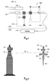
- FIG. 1 shows an optical system 100 of ranging elements with a camera 150 in a prior art laser tracker and a separated HeNe laser light source 110.
- An absolute distance meter 130 with a laser diode 131 and an interferometer 120 are placed together with the camera 150, in particular a zoom camera, in such a way that it moves simultaneously during a movement of the system 100, for example during a pivoting of the entire system 171 carrying the system 100 we will change their orientation together.
- the camera 150 has its own optical system with an optical axis 162, which is substantially parallel to an absolute distance meter 130 and the
- Interferometeran extract 120 common optical axis 161 extends.
- the HeNe laser 110 is attached to a base unit 172, e.g. a support or fixed base, installed separately and we are not moved with the structure 171, but provides the system 100, in particular the interferometer 120, by means of a light guide 109, a generated measuring radiation available.
- a base unit 172 e.g. a support or fixed base, installed separately and we are not moved with the structure 171, but provides the system 100, in particular the interferometer 120, by means of a light guide 109, a generated measuring radiation available.
- a distance to a target can be determined, wherein a precise distance to the target and a distance change can be continuously determined by taking measurements of the interferometer 120 into consideration.
- FIG. 2 shows a laser tracker 70 according to the invention with an image acquisition unit 75 and a measuring auxiliary instrument 80, for example a feeler tool.
- the image capture unit 75 has a CMOS or is designed in particular as a CCD or pixel sensor array camera. Such sensors allow a position-sensitive detection of detected exposure.
- the auxiliary measuring instrument 80 has a sensor whose contact point 83 can be brought into contact with a target object to be measured. While this contact between the stylus 80 and the target object is made, a position of the contact point 83 in the space and thus the coordinates of a point on the target can be accurately determined.
- markers 82 which may be formed for example as light-emitting diodes.
- the markers 82 may also be formed such that they in the case of illumination, eg with radiation of a defined wavelength, which reflects incident radiation (auxiliary point markers 82 designed as retro reflectors), in particular show a specific luminous characteristic, or that these have a defined pattern or color coding. From the position or distribution of the markers 82 in an image captured by the sensor of the image capture unit 75, an orientation of the feeler tool 80 can be determined.
- a measuring laser beam 76 is emitted by the laser tracker 70 in the direction of the reflector 81 arranged on the auxiliary measuring instrument 80, reflected back from there to the tracker 70 in parallel, and detected at the tracker 70 by means of a receiving unit.
- the laser tracker 70 has distance measuring means for determining a distance between the tracker 70 and the reflector 81 and via protractors, which make a position of a beam steering unit, by means of which the laser beam 76 can be aligned and guided defined, and thus a propagation direction of the laser beam 76 determinable.
- the alignment of the laser beam 76 can be effected in particular by pivoting the beam steering unit, in particular a targeting unit, in which a beam-guiding optics and in particular at least one beam source can be installed, or a mirror.
- an absolute distance meter and in particular for determining changes in distance between the tracker 70 and the reflector 81 an interferometer are integrated into the tracker 70.
- the absolute distance meter has a first laser diode for generating a measuring radiation and thus allows a determination of a distance to the target or reflector 81, for example by means of transit time measurement, according to the phase measurement principle or the Fizeau principle.
- the interferometer is provided with a further measuring radiation from a second laser diode. In this case, this measuring radiation can be emitted at the laser diode such that the radiation enters directly into the interferometer or can be guided by means of an optical fiber to the interferometer and coupled into this.
- the second laser diode is configured in such a way that the measuring radiation that can be generated with it is single-mode and has a large coherence length, in particular of at least 10 m, preferably 50 m. For precise distance determination, measurements from both distance measuring means can be used together and linked.
- Advantages for such use of a long coherence length laser diode for an interferometer in a laser tracker 70 are e.g. in the space requirement for the laser diode (which is substantially lower than that for a HeNe gas laser, which is an alternative beam source for it), in the relatively low power consumption, in the rapidly producible measuring beam emission of the diode after activation of the system and the possibility of a high voltage power supply ( eg needed for a HeNe gas laser) to be able to do without.
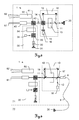
- FIG. 3 shows an inventive arrangement of optical components with a laser diode 20 as a beam source for an interferometer 10 of an optical system 1 in a laser tracker.
- the system 1 has an absolute distance meter 30 (ADM) with a another beam source 31, for example a laser diode or a SLED (superluminescent LED), and a camera 50.
- ADM absolute distance meter
- the light beam emitted by the beam source 31 of the absolute distance meter 30 is passed through an insulator 32 for shielding returning light to a polarizing beam splitter 33 and from there through an electro-optical modulator 34 to a wavelength-dependent beam splitter 41.
- a beam splitter 41 with wavelength-dependent beam splitting is used in particular at different emission wavelengths of the two light sources 20,31.
- the returning light is guided in the absolute distance meter 30 by the polarizing beam splitter 33 to an ADM detector 35.
- other ADM arrangements and methods can be used in this context in which the measurement light beam can be coupled in and out by, for example, the wavelength-dependent beam splitter 41.
- An example of such a distance meter is in the WO 03/062744 Al revealed.
- other types of ADM such as phase meter, can be used.
- the interferometer 10 uses light which is generated by the laser diode 20.
- this diode 20 is arranged directly on the system 1, wherein this generates a longitudinal monomode laser radiation with a large coherence length (single frequency).
- the measurement radiation thus generated is split by a beam splitter 11 into a reference light path 12 and a measurement light path.
- the measuring light path leads through an acousto-optic modulator 13 and, together with the reference light path, hits one polarizing beam splitter 14.
- the polarizing beam splitter 14 passes the measuring radiation to the wavelength-dependent beam splitter 41, and directs the returning measuring light together with the reference light via a polarizing filter 15 to an interferometer detector 16.
- interferometer 10 The operation of such an interferometer 10 is basically known and based on the wave interference principle.
- other interferometer arrangements and methods can also be used in which the measuring radiation can be coupled in and out by, for example, the wavelength-dependent beam splitter 41.
- An example of such an interferometer is in the WO 03/062744 Al described.
- other types of interferometers eg Michelson with quadrature detection
- the optical system 1 further comprises a ⁇ / 4 plate 43 and a component 42, which light, which incident on the outside of the system 1 along a shared by the absolute distance meter 30 and the interferometer 10 optical axis 61, and a first part of this light coupled to an overview camera and a second to a position transducer.
- the overview camera can have its own optics and additionally an image converter.
- the overview camera typically has an aperture angle of approximately 10 ° and a focal length of, for example, 30-50 mm and serves for coarse localization of measurement targets.
- the system may preferably have a reflector illumination with a particular illumination wavelength, which includes a Illuminated angle range, which is preferably at least as large as the opening angle of the overview camera.
- An evaluation electronics and / or evaluation software of the overview camera then detects, for example, one or more bright points of light in the field of view of the overview camera, which each correspond to a reflecting target. From this, their position in the image of the overview camera and, in turn, a change in the orientation of the target, e.g. of a metering aid (e.g., stylus or scanner), whereby the laser tracker or system 1 and light beams of the distance meter (s) 10, 30 can be aligned with the target.
- a metering aid e.g., stylus or scanner
- the light component for the position transducer is typically a beam of returning light emitted by one of the distance meters 10, 30, preferably from the interferometer assembly 10.
- the position transducer may have its own optics and, for example, a position-sensitive diode. This provides signals representing the position of the beam in two dimensions on a surface of the position sensitive diode.
- sensor arrays or image converters eg CCD or CMOS
- a control unit can according to the determined position, an alignment of the laser tracker so that the measuring beam follows a movement of the reflective target.
- the camera can detect 50 markers of a target with the built-in imager. Due to the mapping of the marks, e.g. the orientation of the target is determined by means of image processing, wherein in addition the zoom factor of the camera 50 can be controlled such that the image of the target on the image converter essentially always has the same size.
- the camera 50 may, for example, have a 10x zoom with a focal length of 50 to 500 mm magnification.
- FIG. 4 shows a further embodiment of an inventive measuring optics 1 of a laser tracker with a laser diode 20 as a beam source for an interferometer 10 and a light guide 9.
- the laser diode 20 is in turn provided for generating the measuring radiation for the interferometer 10 of the laser tracker.
- a zoom camera 50 is provided.
- the laser diode 20 is in this case designed such that a measuring radiation with a high coherence length, in particular a coherence length of at least 10 m and a line width of less than 1 MHz, can be generated.
- the laser diode has a wavelength-selective device, for example a periodic structure (optical grating) of the active laser medium, but a grating outside the active medium installed on the same chip or a grating structure in the external fiber 9, which causes the emitted one Laser radiation longitudinally monomode and thus present with a specific narrow line width (single-mode laser).
- the suitable beam characteristic can be determined by means of a highly stable, external cavity or by means of a holographic grid in conjunction with the diode 20 are generated.
- the laser diode 20 according to the embodiment described above, an emission wavelength of 633 nm (visible red spectral range), which is linearly polarized, is single-mode and has a coherence length of at least 10m.
- the emission power of the radiation is above 0.5 mW with a high wavelength stability over the entire service life ( ⁇ 0.3 ppm) of the diode 20.
- the measuring beam can be used simultaneously as a pointing beam, which can be dispensed with an additional beam source for the visual marking of points.
- the radiation generated by the laser diode 20 is coupled by means of the light guide 9 in the interferometer 10.
- a collimator 8 is further provided for connecting the fiber 9 to the interferometer 10.
- the structure of the interferometer 10 is that of the described inventive embodiment according to FIG. 3 similar, wherein the reference path 12 is guided here by means of a steel divider 17 on the detector 16 and the measuring path 18 by means of the steel divider 11.
- the acousto-optic modulator 13 is provided for frequency variation and as an optical isolator.
- the laser tracker on an absolute distance meter 30 with generic typical optical components (beam source, detector, insulator, etc.).
- the laser tracker has two separate units 71, 72.
- the camera 50, the absolute distance meter 30 and the interferometer 10 are arranged on a beam steering unit 71 together with further, in particular, beam-guiding components.
- This beam steering unit 71 may be formed differently depending on the design of the laser tracker, e.g. as a structurally one-piece aiming unit or as a beam guiding unit (e.g., rotatable mirror) having a measuring unit including the absolute distance meter 30 and the interferometer 10.
- the beam steering unit 71 can be designed to be movable, in particular pivotable about two axes, independently of an orientation or orientation of a base unit 72.
- the laser diode 20 embodied as an interferometer beam source can be present in the base unit 72, the radiation generated by the optical fiber 9 coupled into the beam steering unit 71 and the alignment of the beam steering unit 71 and the optical Axes 61,62 of the camera 50 and the distance meter 10,30 relative to the base 72 are changed.
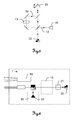
- FIG. 5 shows a basic inventive structure of an interferometer with laser diode 20 for a laser tracker.
- the laser diode is a (longitudinal) single-mode measuring radiation with a Coherence length of at least 10m, preferably 50m, generated, which is performed with beam splitters on the one hand on a reference path 12 and the other on a return path 19.
- the radiation is directed to a reflective target 25 and reflected there.
- an acousto-optic modulator 13 is arranged in the return path 19.
- the target 25 represents a movable target 25, wherein a change in distance to the interferometer by means of the interferometer detector 16 can be detected and measured.
- the reference radiation and the measuring radiation are superimposed on the interferometer detector 16, as a result of which these beams interfere and permit reading of measured values.
- FIG. 6 1 shows a further embodiment of a measuring optics 1 according to the invention of a laser tracker with a laser diode 20 as an interferometer beam source for generating a measuring radiation for an interferometer 10 with a wavelength stabilizing unit 21.
- an absolute distance meter 30 with a further light source 31, preferably embodied as a laser diode or SLED, and a camera 50 is provided.
- the wavelength stabilization unit 21 By means of the wavelength stabilization unit 21, a stabilization of the measurement radiation to a wavelength standard, for example to an absorption line (eg using an iodine cell) of approximately 633 nm, is realized.
- the wavelength stabilization unit 21 may have stabilization via a gas cell.
- different stabilization approaches can be used for stabilization, such as synchronous detection ("synchronous detection”: modulation of the optical frequency about a central absorption line), “side-of-line” method or Stabilization by means of the Zeeman effect at constant optical frequency (with magnetic modulation).
- the "side of line” method is based on a stabilization by absorption at an absorption value, which corresponds to the maximum slope of a corresponding absorption line of a gas cell (eg stabilization at about 40% absorption).
- the laser diode 20 For such a stabilization, light with a modehop-free tunable wavelength range is provided by the laser diode 20, so that it is possible to tune the wavelength to the desired absorption line.
- the generated laser light also has a large coherence length (at least 10m, especially 50m).
- FIG. 7 shows a further embodiment of an inventive measuring optics 1 of a laser tracker with a laser diode 20 for generating a measuring radiation for an interferometer 10, a wavelength stabilization unit 21 and optical fibers 9a, 9b for guiding the laser radiation.
- the single-mode laser radiation generated by the diode 20 is guided to the wavelength stabilization unit 21 by means of the optical fiber 9a.
- This stabilization unit 21 effects a largely constant holding of the wavelength of the laser radiation.
- the thus stabilized radiation is guided by another optical fiber 9b from the wavelength stabilization unit 21 to the interferometer 10. Due to the thus generated measuring radiation having a large coherence length and wavelength stability, measurements of distance changes with the interferometer 10 can be carried out with high precision.
- a spatial and in particular structural separation of the laser diode 20 and the wavelength stabilization unit 21 is achieved by the distance measuring means 10,30 and the camera 50 of the laser tracker by connecting the two units 71,72 by means of the optical fiber 9b.
Abstract
Description
Die Erfindung betrifft ein Messgerät, insbesondere einen Lasertracker, mit einem Interferometer mit Laserdiode zur Bestimmung einer Entfernungsänderung relativ zu einem Ziel nach dem Oberbegriff des Anspruchs 1, eine Verwendung einer Laserdiode mit grosser Kohärenzlänge in einem entsprechenden Interferometer nach Anspruch 13 und ein Verfahren zum Bestimmen einer relativen Entfernung zum Ziel nach Anspruch 14.The invention relates to a measuring device, in particular a laser tracker, with an interferometer with laser diode for determining a distance change relative to a target according to the preamble of
Messvorrichtungen, die für eine fortlaufende Verfolgung eines Zielpunkts und eine koordinative Positionsbestimmung dieses Punkts ausgebildet sind, können allgemein unter dem Begriff Lasertracker zusammengefasst werden. Ein Zielpunkt kann dabei durch eine retro-reflektierende Einheit (z.B. Würfelprisma) repräsentiert sein, die mit einem optischen Messstrahl der Messvorrichtung, insbesondere einem Laserstrahl, angezielt wird. Der Laserstrahl wird parallel zurück zur Messvorrichtung reflektiert, wobei der reflektierte Strahl mit einer Erfassungseinheit der Vorrichtung erfasst wird. Hierbei wird eine Emissions- bzw. Empfangsrichtung des Strahls, beispielsweise mittels Sensoren zur Winkelmessung, die einem Ablenkspiegel oder einer Anzieleinheit des Systems zugeordnet sind, ermittelt. Zudem wird mit dem Erfassen des Strahls eine Distanz von der Messvorrichtung zum Zielpunkt, z.B. mittels Laufzeit-oder Phasendifferenzmessung oder mittels des Fizeau-Prinzips, und - in modernen Systemen zunehmend standardisiert - auf einem Sensor eine Ablage des empfangenen Strahls von einer Nullposition ermittelt.Measuring devices, which are designed for a continuous tracking of a target point and a coordinate position determination of this point, can generally be summarized under the term laser tracker. A target point may be represented by a retro-reflective unit (such as a cube prism) targeted by an optical measuring beam of the measuring device, in particular a laser beam. The laser beam is reflected back parallel to the measuring device, the reflected beam being detected by a detection unit of the device. In this case, an emission or reception direction of the beam, for example by means of sensors for angle measurement, which are assigned to a deflection mirror or a target unit of the system, determined. In addition, with the detection of the beam, a distance from the measuring device to the target point, e.g. by means of transit time or phase difference measurement or by means of the Fizeau principle, and - increasingly standardized in modern systems - determined on a sensor storage of the received beam from a zero position.
Mittels dieser so messbaren Ablage kann eine Positionsdifferenz zwischen dem Zentrum einesBy means of this so measurable filing can be a position difference between the center of a
Retroreflektors und dem Auftreffpunkt des Laserstrahls auf dem Reflektor bestimmt und die Ausrichtung des Laserstrahls in Abhängigkeit dieser Abweichung derart korrigiert bzw. nachgeführt werden, dass die Ablage auf dem Sensor verringert wird, insbesondere "Null" ist, und damit der Strahl in Richtung des Reflektorzentrums ausgerichtet ist. Durch das Nachführen der Laserstrahlausrichtung kann eine fortlaufende Zielverfolgung (Tracking) des Zielpunkts erfolgen und die Entfernung und Position des Zielpunkts fortlaufend relativ zum Messgerät bestimmt werden. Das Nachführen kann dabei mittels einer Ausrichtungsänderung des motorisiert bewegbaren, zur Ablenkung des Laserstrahls vorgesehenen Ablenkspiegels und/oder durch ein Schwenken der Anzieleinheit, die die strahlführende Laseroptik aufweist, realisiert werden.Retroreflektors and the point of impact of the laser beam on the reflector determined and the orientation of the laser beam in response to this deviation are corrected or tracked so that the shelf on the sensor is reduced, in particular "zero", and thus the beam aligned in the direction of the reflector center is. By tracking the laser beam alignment, continuous tracking of the target point can be performed and the distance and position of the target point continuously determined relative to the meter. The tracking can be realized by means of an alignment change of the motorized movable, provided for deflecting the laser beam deflection mirror and / or by pivoting the target unit, which has the beam-guiding laser optics.
Lasertracker nach dem Stand der Technik können zusätzlich mit einer optischen Bilderfassungseinheit mit einem zweidimensionalen, lichtempfindlichen Array, z.B. einer CCD- oder CID-Kamera oder einer auf einem CMOS-Array basierenden Kamera, oder mit einem Pixelarraysensor und mit einer Bildverarbeitungseinheit ausgeführt sein. Der Lasertracker und die Kamera sind dabei insbesondere derart aufeinander montiert, dass ihre Positionen relativ zueinander nicht veränderbar sind. Die Kamera ist beispielsweise zusammen mit dem Lasertracker um dessen im Wesentlichen senkrechte Achse drehbar, jedoch unabhängig vom Lasertracker auf und ab schwenkbar und somit insbesondere von der Optik des Laserstrahls getrennt angeordnet. Insbesondere kann die Kamera über eine Fischaugen-Optik verfügen und somit ein Schwenken der Kamera aufgrund eines sehr grossen Bilderfassungsbereichs der Kamera vermieden oder zumindest eingeschränkt nötig sein. Weiters kann die Kamera - z.B. in Abhängigkeit der jeweiligen Anwendung - nur um eine Achse schwenkbar ausgeführt sein. In alternativen Ausführungen kann die Kamera in integrierter Bauweise mit der Laseroptik zusammen in einem gemeinsamen Gehäuse verbaut sein.Prior art laser trackers may additionally be implemented with an optical imaging unit having a two-dimensional photosensitive array, eg a CCD or CID camera or a CMOS array based camera, or with a pixel array sensor and with an image processing unit. In particular, the laser tracker and the camera are mounted on one another in such a way that their positions relative to one another can not be changed. The camera is rotatable, for example, together with the laser tracker about its substantially vertical axis, but independently of the laser tracker up and down pivotally and thus arranged in particular separated from the optics of the laser beam. In particular, the camera may have a fisheye lens and thus avoids pivoting of the camera due to a very large image capture range of the camera or at least partially necessary be. Furthermore, the camera - for example, depending on the particular application - be performed only pivotable about an axis. In alternative embodiments, the camera can be installed in integrated construction with the laser optics together in a common housing.
Mit dem Erfassen und Auswerten eines Bildes - mittels Bilderfassungs- und Bildverarbeitungseinheit - eines so genannten Messhilfsinstruments mit Markierungen, deren relative Lage zueinander bekannt ist, kann so auf eine Orientierung eines an dem Messhilfsinstrument angeordneten Objekts (z.B. eine Sonde) im Raum geschlossen werden. Zusammen mit der bestimmten räumlichen Position des Zielpunkts kann ferner die Position und Orientierung des Objekts im Raum absolut und/oder relativ zum Lasertracker präzise bestimmt werden.By detecting and evaluating an image - by means of an image acquisition and image processing unit - of a so-called auxiliary measuring instrument with markings whose relative position to each other is known, an orientation of an object (for example a probe) arranged in the auxiliary measuring instrument in space can be deduced. Furthermore, together with the determined spatial position of the target point, the position and orientation of the object in space absolutely and / or relative to the laser tracker can be precisely determined.
Das Objekt, dessen Position und Orientierung mit dem genannten Messgerät vermessen wird, muss damit beispielsweise nicht eine Messsonde selbst sondern kann das Messhilfsinstrument sein. Dieses wird als Teil des Messsystems für die Vermessung in eine relativ zum Zielobjekt mechanisch definierte oder während der Vermessung bestimmbare Position gebracht, wobei über dessen vermessene Position und Orientierung auf die Position und gegebenenfalls die Orientierung beispielsweise der Messsonde geschlossen werden kann.For example, the object whose position and orientation is measured with the aforementioned measuring device does not have to be a measuring probe itself but can be the auxiliary measuring instrument. This is brought as part of the measuring system for the measurement in a relative to the target object mechanically defined or determinable during the measurement position, which can be closed about its measured position and orientation to the position and, where appropriate, the orientation, for example, the probe.
Derartige Messhilfsinstrumente können durch so genannte Tastwerkzeuge, die mit ihrem Kontaktpunkt auf einem Punkt des Zielobjektes positioniert werden, verkörpert sein. Das Tastwerkzeug weist Markierungen, z.B. Lichtpunkte, und einen Reflektor auf, der einen Zielpunkt am Tastwerkzeug repräsentiert und mit dem Laserstrahl des Trackers anzielbar ist, wobei die Positionen der Markierungen und des Reflektors relativ zum Kontaktpunkt des Tastwerkzeuges präzise bekannt sind. Das Messhilfsinstrument kann in dem Fachmann bekannter Weise auch ein beispielsweise von Hand gehaltener, zur Distanzmessung ausgerüsteter Scanner für berührungslose Oberflächenvermessungen sein, wobei Richtung und Position des für die Distanzmessung verwendeten Scanner-Messstrahles relativ zu den Lichtpunkten und Reflektoren, die auf dem Scanner angeordnet sind, genau bekannt sind. Ein derartiger Scanner ist beispielsweise in der
Zur Entfernungsmessung weisen Lasertracker des Standes der Technik zumindest einen Distanzmesser auf, wobei dieser z.B. als Interferometer ausgebildet sein kann. Da solche Entfernungsmesseinheiten nur relative Distanzänderungen messen können, werden in heutigen Lasertrackern zusätzlich zu Interferometern so genannte Absolutdistanzmesser verbaut. Beispielsweise ist eine derartige Kombination von Messmitteln zur Entfernungsbestimmung durch das Produkt LTD500 der Leica Geosystems AG bekannt.For distance measurement, laser trackers of the prior art comprise at least one distance meter, this being known e.g. can be designed as an interferometer. Since such distance measuring units can only measure relative distance changes, in today's laser trackers so-called absolute distance meters are installed in addition to interferometers. For example, such a combination of measuring means for determining the distance is known by the LTD500 product of Leica Geosystems AG.
Die in diesem Zusammenhang für die Distanzmessung eingesetzten Interferometer verwenden hauptsächlich - aufgrund der grossen Kohärenzlänge und der damit ermöglichten Messreichweite - als Lichtquellen HeNe-Gaslaser. Die Kohärenzlänge des HeNe-Lasers kann dabei einige hundert Meter betragen, so dass mit relativ einfachen Interferometer-Aufbauten die in der industriellen Messtechnik geforderten Reichweiten erzielt werden können. Eine Kombination eines Absolutdistanzmessers und eines Interferometers zur Entfernungsbestimmung mit einem HeNe-Laser ist beispielsweise aus der
Nachteilig an der Verwendung von HeNe-Laserlichtquellen ist im Hinblick auf eine allgemein angestrebte Miniaturisierung von Lasertrackern jedoch deren die Lichtleistung bestimmende Grösse. Die Leistung der Lichtquelle hängt dabei signifikant von der Länge der Laserröhre ab, d.h. je länger die Röhre desto grösser die erreichbare Emissionsleistung. Zudem zeigt eine derartige Laserquelle gewöhnlich eine relativ grosse Leistungsdissipation. Einen weiteren Nachteil stellt die für den Betrieb benötigte Hochspannungsversorgung dar. Beispielsweise muss für die Zündung des Lasers eine Spannung von ca. 7'000V und während des Betriebs eine Spannung von ca. 1'500V bereitgestellt werden, wodurch bei der Verwendung solcher Lichtquellen spezielle Komponenten (z.B. Hochspannungsnetzteil und Abschirmung) eingesetzt und Sicherheitsmassnahmen getroffen werden müssen. Auch die Empfindlichkeit gegenüber Magnetfeldern (z.B. erzeugt durch interne Motoren oder externe Schweisstrafos) und die begrenzte Lebensdauer der Röhren (typischerweise ca. 15'000 Betriebsstunden) gestalten den Einsatz von HeNe-Lasern nachteilig - beispielsweise da die Lichtquellen oft kostspielig in den Systemen ersetzt werden müssen.A disadvantage of the use of HeNe laser light sources, however, in terms of a generally desired miniaturization of Lasertrackern whose determining the light output size. The power of the light source depends significantly on the length of the laser tube, i. the longer the tube, the greater the achievable emission power. In addition, such a laser source usually exhibits a relatively large power dissipation. A further disadvantage is the high-voltage supply required for the operation. For example, for the ignition of the laser a voltage of approximately 7,000V and during operation a voltage of approximately 1,500V must be provided, whereby special components are used when using such light sources (eg high voltage power supply and shielding) used and security measures must be taken. The sensitivity to magnetic fields (eg generated by internal motors or external welding transformers) and the limited life of the tubes (typically about 15,000 operating hours) also make the use of HeNe lasers disadvantageous - for example because the light sources are often replaced costly in the systems have to.
Es ist eine Aufgabe der vorliegenden Erfindung, einen verbesserten Lasertracker bereitzustellen, wobei die Mittel zur Erzeugung einer Laserstrahlung zur Entfernungsmessung in ihrer Gesamtheit kompakter ausgebildet sind und eine zur Entfernungsbestimmung emittierte Laserstrahlung dabei derart erzeugbar ist, dass eine geforderte Präzision für die Entfernungsbestimmung bei im Rahmen einer industriellen Vermessung geforderter grosser Messreichweite, insbesondere bei einer Mindestreichweite 10m, mindestens erreicht wird.It is an object of the present invention to provide an improved laser tracker, wherein the means for generating a laser radiation for distance measurement are made more compact in their entirety and emitted to determine the distance laser radiation is generated such that a required precision for the distance determination in a industrial measurement of required large measuring range, in particular at a minimum range of 10m, at least achieved.
Eine spezielle Aufgabe der Erfindung ist es einen Lasertracker mit einer hinsichtlich des Platzbedarfs verbesserten Entfernungsmesseinheit bereitzustellen, wobei eine geforderte Präzision bei einer gleichzeitig geforderten Messreichweite von mindestens 10m für die Entfernungsbestimmung mindestens erhalten bleibt.A specific object of the invention is to provide a laser tracker with an improved distance measuring unit in terms of space, wherein a required precision is at least maintained for a distance measurement of at least 10 m required for the distance determination.
Eine weitere spezielle Aufgabe der Erfindung ist es, einen Lasertracker mit einem Interferometer als Distanzmesser bereitzustellen, wobei die optischen Komponenten, insbesondere die Strahlquelle und dafür vorzusehende Versorgungseinheiten, gegenüber dem Stand der Technik einen deutlich geringeren Platzbedarf und geringeren Energieverbrauch aufweisen.A further specific object of the invention is to provide a laser tracker with an interferometer as a distance meter, the optical components, in particular the beam source and supply units to be provided for this, having a significantly smaller space requirement and lower energy consumption compared to the prior art.
Diese Aufgaben werden durch die Verwirklichung der kennzeichnenden Merkmale der unabhängigen Ansprüche gelöst. Merkmale, die die Erfindung in alternativer oder vorteilhafter Weise weiterbilden, sind den abhängigen Patentansprüchen zu entnehmen.These objects are achieved by the realization of the characterizing features of the independent claims. Features which further develop the invention in an alternative or advantageous manner can be found in the dependent claims.
Die Erfindung betrifft einen Lasertracker zur fortlaufenden Verfolgung eines reflektierenden Ziels und zur Entfernungsbestimmung zu dem Ziel mit einer eine Stehachse definierenden Basis und einer Strahllenkeinheit zur Emission einer Messstrahlung und zum Empfang von zumindest einem Teil der am Ziel reflektierten Messstrahlung, wobei die Strahllenkeinheit um die Stehachse und eine im Wesentlichen orthogonal zur Stehachse stehende Neigungsachse relativ zur Basis motorisiert schwenkbar ist. Hierbei sind die Stehachse und die Neigungsachse derart zueinander positioniert, dass zwischen den Achsen ein Winkel von genau 90° bzw. von ungefähr 90°, z.B. 88,5°, vorliegt, wobei eine relative Achsstellung exakt definiert und korrespondierende Stellungswerte im Lasertracker hinterlegt sein können, insbesondere für eine Kompensation von Messwerten. Zudem verfügt der Lasertracker über eine als Interferometer ausgebildete Entfernungsmesseinheit, insbesondere mit einer definierten Detektorbandbreite, z.B. von 50MHz, zur Bestimmung einer Entfernungsänderung zum Ziel mittels Interferometrie, eine Interferometer-Laserstrahlquelle zur Erzeugung der Messstrahlung für das Interferometer und eine Winkelmessfunktionalität zur Bestimmung einer Ausrichtung der Strahllenkeinheit relativ zur Basis. Die Interferometer-Laserstrahlquelle ist dabei als Laserdiode ausgebildet, wobei die Laserdiode ferner derart ausgebildet ist, dass die Messstrahlung longitudinal monomodig mit einer definierten Emissionswellenlänge und mit einer Kohärenzlänge von mindestens 10m erzeugbar ist, insbesondere wobei die Kohärenzlänge von mindestens 10m mittels des Interferometers bestimmbar ist. Insbesondere kann die Laserdiode dabei derart ausgebildet sein, dass die Messstrahlung mit einer Kohärenzlänge von mindestens 20m, insbesondere mindestens 50m, erzeugbar ist.The invention relates to a laser tracker for continuously tracking a reflecting target and determining distance to the target with a standing axis defining base and a beam steering unit for emitting a measuring radiation and for receiving at least a portion of the measuring radiation reflected at the target, wherein the beam steering unit about the vertical axis and a substantially orthogonal to the standing axis standing axis of inclination is motorized pivotable relative to the base. Here, the standing axis and the tilt axis are positioned to each other such that between the axes an angle of exactly 90 ° or of approximately 90 °, for example 88.5 °, is present, with a relative axis position defined exactly and corresponding position values can be stored in the laser tracker, in particular for a compensation of measured values. In addition, the laser tracker has a distance measuring unit designed as an interferometer, in particular with a defined detector bandwidth, eg of 50 MHz, for determining a change in distance to the target by means of interferometry, an interferometer laser beam source for generating the measuring radiation for the interferometer and an angle measuring functionality for determining an alignment of the beam steering unit relative to the base. The interferometer laser beam source is designed as a laser diode, wherein the laser diode is further formed such that the measurement radiation is generated longitudinally monomodal with a defined emission wavelength and with a coherence length of at least 10m, in particular wherein the coherence length of at least 10m by means of the interferometer can be determined. In particular, the laser diode can be designed such that the measuring radiation can be generated with a coherence length of at least 20 m, in particular at least 50 m.
Die erfindungsgemässe Verwendung einer spezifischen Laserdiode mit dem Interferometer des Lasertrackers bietet Vorteile hinsichtlich des damit verbunden Platzbedarfs, der gegenüber einem HeNe-Gaslaser deutlich geringer ausfällt bei jedoch ebenfalls grosser Kohärenzlänge. Im Gegensatz zu einer solchen Gaslaserquelle, die zwar ebenfalls Messstrahlung mit geeigneter Kohärenzlänge bereitstellen kann, wird für den Betrieb der Diode zudem keine Hochspannungsversorgung benötigt. Des Weiteren weisen derartige Laserdioden einen geringeren Energieverbrauch auf.The use according to the invention of a specific laser diode with the interferometer of the laser tracker offers advantages in terms of the associated space requirement, which is significantly lower than that of a HeNe gas laser but also of great coherence length. In contrast to such a gas laser source, which can also provide measuring radiation with a suitable coherence length, no high-voltage supply is required for the operation of the diode. Furthermore, such laser diodes have a lower energy consumption.
Für die erfindungsgemässe Verwendung mit einem Interferometer ist eine grosse Kohärenzlänge der mit der Diode emittierbaren Laserstrahlung von einigen zehn Metern erforderlich. Zur Bereitstellung solcher Kohärenzen können die Laserdioden bzw. Diodenlaser, welche erfindungsgemäss in diesem Zusammenhang eingesetzt werden eine wellenlängenselektive Vorrichtung aufweisen. Als Strahlquellen können z.B.
- Distributed Feedback Laser (DFB) (mit einem periodisch strukturierten aktiven Medium, z.B. Gitter),
- Distributed Bragg Reflector Laser (DBR) (mit einem optischen Gitter ausserhalb des aktiven Mediums aber auf einem gemeinsamen Chip angeordnet),
- Fiber Bragg grating laser (FBG) (im Wesentlichen gemäss einem DFB-Laser, jedoch mit einem Gitter in einer externen Faser),
- External Cavity Diode Laser (ECDL) (Stabilisierung der Laserdiode mittels einer externen hochstabilen Kavität z.B. mit einem holografischen Gitter),
- Diode pumped solid state lasers (DPSS),
- Discrete mode lasers (DMD) und/oder
- Microchip Laser
- Distributed Feedback Laser (DFB) (with a periodically structured active medium, eg grid),
- Distributed Bragg Reflector Laser (DBR) (with an optical grating outside the active medium but arranged on a common chip),
- Fiber Bragg Grating Laser (FBG) (essentially according to a DFB laser, but with a grating in an external fiber),
- External Cavity Diode Laser (ECDL) (stabilization of the laser diode by means of an external highly stable cavity eg with a holographic grating),
- Diode pumped solid state lasers (DPSS),
- Discrete mode lasers (DMD) and / or
- Microchip laser
Hinsichtlich der mit der Diode emittierten Wellenlänge sind Emissionsspektralbereiche vorteilhaft, welche im sichtbaren optischen Bereich, insbesondere im "roten Wellenlängenbereich", oder im nahen Infrarotbereich liegen. Somit kann die Emissionswellenlänge der Messstrahlung erfindungsgemäss zwischen 600nm und 700nm, insbesondere zwischen 630nm und 635nm, oder zwischen 850nm und 900nm, insbesondere zwischen 850nm und 855nm oder zwischen 892nm und 896nm, liegen. In einer Ausführung mit einer Emissionswellenlänge im sichtbaren Wellenlängenbereich (z.B. zwischen 630 und 635nm) kann das emittierte rote Laserlicht der Diode nicht nur für interferometrische Messungen sondern auch als Markierungslicht verwendet werden. Mit der Erzeugung eines roten Spots auf einem Zielobjekt kann beispielsweise einem Benutzer des Lasertrackers ein Anzielpunkt visuell sichtbar gemacht werden.With regard to the wavelength emitted by the diode, emission spectral ranges which are in the visible optical range, in particular in the "red wavelength range" or in the near infrared range, are advantageous. Thus, according to the invention, the emission wavelength of the measuring radiation can be between 600 nm and 700 nm, in particular between 630 nm and 635 nm, or between 850 nm and 900 nm, in particular between 850 nm and 855 nm or between 892 nm and 896 nm. In an embodiment with an emission wavelength in the visible wavelength range (e.g., between 630 and 635 nm), the emitted red laser light of the diode can be used not only for interferometric measurements but also as marker light. With the creation of a red spot on a target object, for example, a target of the laser tracker can be visualized visually.
Eine Ansteuerung der Laserdiode bildet einen weiteren Aspekt der Erfindung. In diesem Zusammenhang kann der Lasertracker erfindungsgemäss eine Steuerungseinheit aufweisen und die Laserdiode derart ausgebildet sein, dass die Emissionswellenlänge der Messstrahlung innerhalb eines bestimmten Emissionswellenlängenbereichs longitudinal monomodig variierbar ist. Dabei kann die Emissionswellenlänge durch eine Temperaturänderung der Laserdiode und/oder eine Änderung eines an der Laserdiode anliegenden elektrischen Stroms gesteuert durch die Steuerungseinheit variierbar sein. Ferner kann vermittels der Steuerungseinheit die Laserdiode derart ansteuerbar sein, dass eine Emissionsleistung der Messstrahlung variierbar ist.An activation of the laser diode forms a further aspect of the invention. In this context, the laser tracker according to the invention can have a control unit and the laser diode can be designed such that the emission wavelength of the measurement radiation can be varied longitudinally monomodally within a specific emission wavelength range. In this case, the emission wavelength can be varied by a temperature change of the laser diode and / or a change of an applied voltage applied to the laser diode controlled by the control unit. Furthermore, the laser diode can be driven in such a way by means of the control unit be that an emission power of the measuring radiation is variable.
Durch diese Variationsmöglichkeit der Wellenlänge innerhalb eines bestimmten Bereichs, wobei die emittierte Strahlung einmodig vorliegt, d.h. im Wesentlichen mit einer bestimmten, scharf definierten Wellenlänge (geringe Linienbreite), kann ein durchstimmbarer und insbesondere modehop-freier Wellenlängenbereich für die Emissionswellenlänge bereitgestellt werden. Mittels dieses spezifischen Bereichs kann ausserdem eine Abstimmung der Strahlung auf eine durch eine Wellenlängenstabilisierungseinheit definierte Absorptionslinie erfolgen.By this variation possibility of the wavelength within a certain range, whereby the emitted radiation is single-modal, i. essentially with a specific, sharply defined wavelength (narrow linewidth), a tunable and, in particular, fashion-hop-free wavelength range can be provided for the emission wavelength. By means of this specific region, the radiation can also be tuned to an absorption line defined by a wavelength stabilization unit.
Erfindungsgemäss kann der Lasertracker hierzu eine Wellenlängenstabilisierungseinheit zur Stabilisierung der von der Laserdiode erzeugten Messstrahlung aufweisen, sodass die Emissionswellenlänge fortlaufend innerhalb eines definierten Wellenlängenbereichs vorliegt, insbesondere wobei die Wellenlängenstabilisierungseinheit als Absorptionszelle ausgebildet ist. Eine solche Stabilisierung kann für die Verwendung der Laserdiode als Lichtquelle für das Interferometer vorteilhaft bzw. in Abhängigkeit der Strahlqualität der Quelle notwendig sein. Z.B. kann die Wellenlängenstabilisierungseinheit als externe Gaszelle mit definierter Absorptionslinie (Absorptionszelle) ausgebildet sein (z.B. Iodzelle für 633nm).According to the invention, the laser tracker can for this purpose have a wavelength stabilization unit for stabilizing the measurement radiation generated by the laser diode so that the emission wavelength is continuously within a defined wavelength range, in particular wherein the wavelength stabilization unit is designed as an absorption cell. Such stabilization may be necessary for the use of the laser diode as a light source for the interferometer advantageous or depending on the beam quality of the source. For example, For example, the wavelength stabilization unit may be formed as an external gas cell with a defined absorption line (absorption cell) (e.g., 633 nm iodine cell).
Ferner kann der Lasertracker erfindungsgemäss eine optische Verbindungsfaser zur Verbindung der Wellenlängenstabilisierungseinheit mit der Interferometer-Laserstrahlquelle aufweisen. So kann die mit der Laserstrahlquelle erzeugte Strahlung mittels der Verbindungsfaser zur Wellenlängenstabilisierungseinheit geführt und in diese eingekoppelt werden.Furthermore, according to the invention, the laser tracker can have an optical connecting fiber for connecting the wavelength stabilizing unit to the interferometer laser beam source. Thus, the radiation generated by the laser beam source by means of Connection fiber guided to the wavelength stabilization unit and coupled into this.
Hinsichtlich der Führung der Messstrahlung ausgehend von der erzeugenden Strahlquelle bis hin zur Strahllenkeinheit und einer anschliessende erfolgenden Aussendung kann erfindungsgemäss der Lasertracker allgemein zumindest eine optische Faser aufweisen, wobei die Messstrahlung vermittels der optischen Faser führbar ist, insbesondere zum Interferometer führbar ist, insbesondere wobei die durch die Laserdiode erzeugbare Messstrahlung in die optische Faser eingekoppelt wird. Zudem kann damit die Messstrahlung mittels der optischen Faser in die Strahllenkeinheit einkoppelbar sein.With regard to the guidance of the measuring radiation starting from the generating beam source up to the beam steering unit and a subsequent transmission, according to the invention, the laser tracker generally have at least one optical fiber, wherein the measuring radiation is feasible by means of the optical fiber, in particular to the interferometer can be guided, in particular wherein by the laser diode generated measuring radiation is coupled into the optical fiber. In addition, the measuring radiation can thus be coupled into the beam steering unit by means of the optical fiber.
Mittels der Strahlführung durch eine optische Faser können beispielsweise optische Komponenten wie die Wellenlängenstabilisierungseinheit oder Strahlquelle in unterschiedlichen Teilen des Lasertrackers angeordnet sein. So kann die Strahlquelle beispielsweise in der Basis oder einer Stütze des Trackers und die Stabilisierungseinheit in einer Anzieleinheit (oder umgekehrt) integriert sein. Dadurch kann die Flexibilität hinsichtlich des strukturellen Aufbaus des Trackers erhöht werden.By means of the beam guidance through an optical fiber, for example, optical components such as the wavelength stabilization unit or beam source can be arranged in different parts of the laser tracker. Thus, the beam source may for example be integrated in the base or a support of the tracker and the stabilization unit in a targeting unit (or vice versa). This can increase the flexibility in terms of the structural design of the tracker.
Den Aufbau des Trackers weiters betreffend kann der Lasertracker erfindungsgemäss eine um die Stehachse relativ zur Basis schwenkbare Stütze aufweisen und die Strahllenkeinheit als um die Neigungsachse relativ zur Stütze schwenkbare Anzieleinheit ausgebildet sein. In einer solchen Ausführungsform kann der Laserstrahl durch ein im Wesentlichen horizontales (azimutales) Schwenken der Stütze relativ zur Basis und ein im Wesentlichen vertikales (elevatives) Schwenken der Anzieleinheit relativ zur Stütze ausgerichtet werden. Zudem kann eine Führung des Messstrahls entsprechend einer Positionsänderung des reflektierenden Ziels (z.B. Retroreflektor an einem Tastwerkzeug) mittels eines derartigen, durch Stellmotoren bereitgestellten Schwenkens erfolgen.With regard to the structure of the tracker, the laser tracker may according to the invention have a support pivotable about the standing axis relative to the base, and the beam steering unit may be formed as a targeting unit pivotable relative to the support about the inclination axis. In such an embodiment, the laser beam may be caused by pivoting the support substantially horizontally (azimuthally) relative to the base and pivoting the aiming unit substantially vertically (elevatively) relative to the support be aligned. In addition, a guidance of the measuring beam in accordance with a change in position of the reflecting target (eg retroreflector on a feeler tool) can take place by means of such pivoting provided by servomotors.
Erfindungsgemäss kann die Laserdiode dabei in der Anzieleinheit angeordnet sein, wobei die damit verbundene Platzersparnis (gegenüber der bisherigen Verwendung von Gaslaser-Strahlquellen) einen deutlichen Vorteil hinsichtlich der konstruktiven Konzeption des Lasertrackers darstellen kann.According to the invention, the laser diode can be arranged in the targeting unit, wherein the associated space savings (compared to the previous use of gas laser beam sources) can represent a significant advantage in terms of constructive design of the laser tracker.
Ein weiterer Aspekt der Erfindung betrifft die Bestimmung einer präzisen Entfernung zu einem Ziel. Der Lasertracker kann hierzu zusätzlich eine Absolutdistanzmesseinheit zur Bestimmung einer Distanz zum Ziel aufweisen, insbesondere nach dem Prinzip der Laufzeitmessung und/oder nach dem Phasenmessprinzip und/oder nach dem Fizeau-Prinzip. Ausserdem kann eine Präzisionsentfernung zum Ziel in Abhängigkeit der mittels der Absolutdistanzmesseinheit bestimmten Distanz und der mittels der Entfernungsmesseinheit bestimmten Entfernungsänderung bestimmbar sein. Durch die Berücksichtigung von Messungen von sowohl dem Interferometer als auch dem Entfernungsmesser (Absolutdistanzmesser) kann die präzise Entfernung zum Ziel bestimmt und fortlaufend aktualisiert werden. Das Interferometer stellt hierbei hochgenaue Entfernungsmesswerte zur Verfügung. Die beiden Distanzmessvorrichtungen können jeweils eine Strahlquelle insbesondere mit unterschiedlichen Emissionswellenlängen (z.B. in Abhängigkeit des jeweils verbauten Detektors) aufweisen.Another aspect of the invention relates to determining a precise distance to a target. For this purpose, the laser tracker can additionally have an absolute distance measurement unit for determining a distance to the target, in particular according to the principle of transit time measurement and / or according to the phase measurement principle and / or according to the Fizeau principle. In addition, a precision distance to the destination can be determined as a function of the distance determined by means of the absolute distance measuring unit and the distance change determined by means of the distance measuring unit. By taking measurements from both the interferometer and the range finder (absolute distance meter), the precise distance to the target can be determined and continuously updated. The interferometer provides highly accurate distance readings. The two distance measuring devices can each have a beam source, in particular with different emission wavelengths (eg, depending on the respectively installed detector).
Die Erfindung betrifft ferner die Verwendung einer Laserdiode, die zur Erzeugung einer longitudinal monomodigen Messstrahlung mit einer definierten Emissionswellenlänge und einer Kohärenzlänge von mindestens 10m, insbesondere mindestens 20m bzw. 50m, ausgebildet ist, in einer als Interferometer ausgebildeten Entfernungsmesseinheit eines Lasertrackers zur Bestimmung einer Entfernungsänderung zu einem Ziel durch Interferometrie mittels der durch die Laserdiode erzeugbaren Messstrahlung.The invention further relates to the use of a laser diode which is designed to generate a longitudinal monomode measuring radiation having a defined emission wavelength and a coherence length of at least 10 m, in particular at least 20 m or 50 m, in a distance measuring unit designed as an interferometer of a laser tracker for determining a change in distance a target by interferometry by means of the measuring radiation generated by the laser diode.
Die Laserdiode bzw. Interferometer-Strahlquelle und die weiteren strahlbeeinflussenden Komponenten (z.B. Wellenlängenstabilisierungseinheit) können im Rahmen der Erfindung in unterschiedlichen Ausführungsformen vorliegen. So kann beispielsweise sichtbar rote (z.B. nahe 633nm), wellenlängenstabilisierte Laserstrahlung erzeugt werden, wobei eine hohe Kompatibilität zu bereits verfügbaren Systemkomponenten (z.B. Retroreflektoren) erreichbar ist und zudem kein zusätzlicher sichtbarer Pointer notwendig wird. Die Lichtquelle und Absorptionszelle (zur Stabilisierung der Wellenlänge) können räumlich getrennt sein, z.B. die Lichtquelle im Teleskop des Trackers und über eine Faser mit der Absorptionszelle in der Stütze verbunden.The laser diode or interferometer beam source and the other beam-influencing components (for example wavelength stabilization unit) may be present in different embodiments within the scope of the invention. Thus, for example, visible red (e.g., near 633 nm), wavelength stabilized laser radiation can be generated, with high compatibility with already available system components (e.g., retroreflectors) achievable and, in addition, no additional visible pointer becomes necessary. The light source and absorption cell (to stabilize the wavelength) may be spatially separated, e.g. the light source in the telescope of the tracker and connected via a fiber to the absorption cell in the support.
In einer weiteren Ausführung kann die Laserdiode zur Emission von sichtbar, nicht-wellenlängenstabilisierter Strahlung ausgebildet sein. Beispielsweise für die Strahlungsversorgung in einem Referenzinterferometer (zusammen mit einem Absolutdistanzmesser) kann eine solche nicht-stabilisierte Laserstrahlung eingesetzt werden. Insbesondere ist dabei die genaue Kenntnis der vorliegenden Wellenlänge nicht erforderlich (diese kann in einer Messung genügend genau bestimmt werden). Da diese nur für die wenigen Millisekunden einer Absolutdistanzmessung konstant sein muss, stellen somit Langzeitdrifts der Wellenlänge kein Problem dar, und eine reine Wellenlängenstabilisierung über Strom- und Temperaturstabilisierung der Lichtquelle ist ausreichend.In a further embodiment, the laser diode can be designed to emit visible, non-wavelength-stabilized radiation. For example, for the radiation supply in a reference interferometer (together with an absolute distance meter), such non-stabilized laser radiation can be used. In particular, the exact knowledge of the present wavelength is not required (this can in one measurement be determined with sufficient accuracy). Since this only has to be constant for the few milliseconds of an absolute distance measurement, long-term drifts of the wavelength are therefore no problem, and pure wavelength stabilization via current and temperature stabilization of the light source is sufficient.
Zusätzlich können mit dem Referenzinterferometer in der Zeit zwischen zwei Messungen des Absolutdistanzmessers (z.B. mit einer Messrate von 50 Hz) Messungen mit einer höheren Messrate (z.B. 1000 Hz) durchgeführt werden, wobei die aktuelle Interferometerwellenlänge fortlaufend, z.B. bei jeder Absolutdistanzmessung, bestimmt und dazwischen interpoliert wird.Additionally, with the reference interferometer, measurements may be made at a higher sampling rate (e.g., 1000 Hz) in the time between two measurements of the absolute distance meter (e.g., at a sampling rate of 50 Hz), with the current interferometer wavelength continuously, e.g. at each absolute distance measurement, determined and interpolated in between.
Diese Ausführung kann hinsichtlich des Platzbedarfs für eine in diesem Zusammenhang einsetzbare sehr kompakte Interferometerlichtquelle vorteilhaft sein. Darüber hinaus könnte daher als Subvariante eine nicht sichtbare Wellenlänge verwendet werden, wobei dann ein zusätzlicher sichtbarer Pointer vorgesehen ist.This embodiment may be advantageous in terms of space requirements for a very compact interferometer light source that can be used in this context. In addition, therefore, a non-visible wavelength could be used as a sub-variant, in which case an additional visible pointer is provided.
Eine weitere Ausführungsform betrifft eine derartige Ausgestaltung des Lasertrackers hinsichtlich der Messstrahlung, dass diese Strahlung eine für eine Miniatur-Absorptionszelle (z.B. Rb, Cs: 780nm, 795nm, 852nm, 894nm) optimierte Wellenlänge aufweist und wellenlängenstabilisiert ist. Damit kann ein deutlich geringerer Platzbedarf (gegenüber rotem Wellenlängenbereich) der optischen Bauteile erzielt werden.Another embodiment relates to such a design of the laser tracker with respect to the measuring radiation that this radiation has a wavelength optimized for a miniature absorption cell (e.g., Rb, Cs: 780nm, 795nm, 852nm, 894nm) and is wavelength stabilized. Thus, a significantly smaller space requirement (compared to red wavelength range) of the optical components can be achieved.
Ausserdem kann im Rahmen einer weiteren Ausführungsform die Strahlung eine Wellenlänge im Telecom-Bereich oder eine beliebige Wellenlänge mit einigen Metern Kohärenzlänge aufweisen und wellenlängenstabilisiert sein. Diese Ausführung bietet insbesondere Platzbedarfsvorteile gegenüber Strahlquellen und damit einsetzbaren Stabilisierungseinheiten, die im roten Wellenlängenbereich emittieren.In addition, in the context of a further embodiment, the radiation can have a wavelength in the telecom range or any wavelength with a few meters of coherence length have and be wavelength stabilized. This embodiment offers in particular space requirements advantages over beam sources and thus usable stabilization units that emit in the red wavelength range.
Weiterhin betrifft die Erfindung ein Verfahren zum Bestimmen einer Entfernungsänderung zu einem Ziel mittels Interferometrie mit einem Lasertracker. Der Lasertracker weist dabei eine eine Stehachse definierende Basis und eine Strahllenkeinheit zum Emittieren einer Messstrahlung und zum Empfangen von zumindest einem Teil der am Ziel reflektierten Messstrahlung auf, wobei die Strahllenkeinheit um die Stehachse und eine im Wesentlichen orthogonal zur Stehachse stehende Neigungsachse relativ zur Basis motorisiert schwenkbar ist. Ausserdem ist eine als Interferometer ausgebildeten Entfernungsmesseinheit zum Bestimmen einer Entfernungsänderung zum Ziel mittels Interferometrie und eine Interferometer-Laserstrahlquelle zum Erzeugen der Messstrahlung für das Interferometer vorgesehen. Weiters erfolgen ein Emittieren der Messstrahlung, ein Empfangen des zumindest einen Teils der am Ziel reflektierten Messstrahlung und das Bestimmen der relativen Entfernung. Dabei ist die Interferometer-Laserstrahlquelle als Laserdiode ausgebildet und zudem die Laserdiode derart ausgebildet, dass die Messstrahlung longitudinal monomodig mit einer definierten Emissionswellenlänge und einer Kohärenzlänge von mindestens 10m erzeugt wird. Insbesondere kann die Laserdiode derart ausgebildet sein, dass die Messstrahlung mit einer Kohärenzlänge von mindestens 20m, insbesondere mindestens 50m, erzeugt wird.Furthermore, the invention relates to a method for determining a change in distance to a target by means of interferometry with a laser tracker. In this case, the laser tracker has a base defining a vertical axis and a beam steering unit for emitting a measuring radiation and for receiving at least part of the measuring radiation reflected at the target, wherein the beam steering unit can be pivoted in a motorized manner about the vertical axis and an inclination axis substantially orthogonal to the vertical axis relative to the base is. In addition, a distance measuring unit designed as an interferometer is provided for determining a change in the distance to the target by means of interferometry and an interferometer laser beam source for generating the measuring radiation for the interferometer. Furthermore, emitting the measuring radiation, receiving the at least part of the measuring radiation reflected at the target and determining the relative distance are carried out. In this case, the interferometer laser beam source is designed as a laser diode and also the laser diode is designed such that the measuring radiation is generated longitudinally monomode with a defined emission wavelength and a coherence length of at least 10m. In particular, the laser diode can be designed such that the measuring radiation is generated with a coherence length of at least 20 m, in particular at least 50 m.
Im Rahmen des erfindungsgemässen Verfahrens kann ferner ein Stabilisieren der von der Laserdiode erzeugten Messstrahlung derart erfolgen, dass die Emissionswellenlänge fortlaufend innerhalb eines definierten Wellenlängenbereichs vorliegt.In the context of the method according to the invention, furthermore, a stabilization of the measuring radiation generated by the laser diode can take place such that the emission wavelength is continuous within a defined wavelength range.
Die erfindungsgemässe Vorrichtung und das erfindungsgemässe Verfahren werden nachfolgend anhand von in den Zeichnungen schematisch dargestellten konkreten Ausführungsbeispielen rein beispielhaft näher beschrieben, wobei auch auf weitere Vorteile der Erfindung eingegangen wird. Im Einzelnen zeigen:
- Fig.1
- eine Anordnung optischer Bauteile zur Entfernungsbestimmung und einer Kamera in einem Lasertracker nach dem Stand der Technik;
- Fig.2
- einen erfindungsgemässen Lasertracker mit einem Interferometer und einer Laserdiode zur Erzeugung einer Messstrahlung für das Interferometer;
- Fig.3
- eine erste Ausführungsform einer erfindungsgemässen Anordnung von optischen Komponenten mit einer Laserdiode als Strahlquelle für ein Interferometer in einem Lasertracker;
- Fig.4
- eine weitere Ausführungsform einer erfindungsgemässen Messoptik eines Lasertrackers mit einer Laserdiode als Strahlquelle für ein Interferometer und einem Lichtleiter;
- Fig.5
- einen erfindungsgemässen Aufbau einer Interferometeranordnung mit Laserdiode für einen Lasertracker;
- Fig.6
- eine weitere Ausführungsform einer erfindungsgemässen Messoptik eines Lasertrackers mit einer Laserdiode mit Wellenlängenstabilisierungseinheit zur Erzeugung einer Messstrahlung für ein Interferometer; und
- Fig.7
- eine weitere Ausführungsform einer erfindungsgemässen Messoptik eines Lasertrackers mit einer Laserdiode, einer Wellenlängenstabilisierungseinheit und Lichtleitern.
- Fig.1
- an arrangement of optical components for distance determination and a camera in a laser tracker according to the prior art;
- Fig.2
- a laser tracker according to the invention with an interferometer and a laser diode for generating a measuring radiation for the interferometer;
- Figure 3
- a first embodiment of an inventive arrangement of optical components with a laser diode as a beam source for an interferometer in a laser tracker;
- Figure 4
- a further embodiment of an inventive measuring optics of a laser tracker with a laser diode as a beam source for an interferometer and a light guide;
- Figure 5
- a construction according to the invention of an interferometer arrangement with laser diode for a laser tracker;
- Figure 6
- a further embodiment of an inventive measuring optics of a laser tracker with a laser diode with wavelength stabilization unit for generating a measuring radiation for an interferometer; and
- Figure 7
- a further embodiment of an inventive measuring optics of a laser tracker with a laser diode, a wavelength stabilization unit and optical fibers.
Ein Absolutdistanzmesser 130 mit einer Laserdiode 131 und ein Interferometer 120 sind zusammen mit der Kamera 150, insbesondere einer Zoomkamera, derart platziert, dass sie bei einer Bewegung des Systems 100, beispielsweise bei einer Schwenkung des gesamten, das System 100 tragenden Aufbaus 171, gleichzeitig bewegt werden uns sich deren Orientierung somit gemeinsam ändert. Dabei weist die Kamera 150 eine eigene Optik mit optischer Achse 162 auf, welche im Wesentlichen parallel zu einer dem Absolutdistanzmesser 130 und derAn
Interferometeranordnung 120 gemeinsamen optischen Achse 161 verläuft.
Der HeNe-Laser 110 hingegen ist an einer Basiseinheit 172, z.B. einer Stütze oder feststehenden Basis, getrennt verbaut und wir nicht mit dem Aufbau 171 mit bewegt, sondern stellt dem System 100, insbesondere dem Interferometer 120, vermittels eines Lichtleiters 109 eine erzeugte Messstrahlung zur Verfügung.The
Mittels des Absolutdistanzmessers 130 kann eine Entfernung zu einem Ziel bestimmt werden, wobei eine präzise Entfernung zum Ziel und eine Entfernungsänderung fortlaufend durch eine Berücksichtigung von Messungen des Interferometers 120 bestimmt werden können.By means of the
Zur Bestimmung der Position wird ein Messlaserstrahl 76 in Richtung des auf dem Messhilfsinstrument 80 angeordneten Reflektors 81 vom Lasertracker 70 emittiert, von dort zum Tracker 70 parallel zurück reflektiert und mittels einer Empfangseinheit am Tracker 70 erfasst. Der Lasertracker 70 verfügt über Distanzmessmittel zur Bestimmung einer Entfernung zwischen dem Tracker 70 und dem Reflektor 81 und über Winkelmesser, die eine Stellung einer Strahllenkeinheit, mittels derer der Laserstrahl 76 definiert ausgerichtet und geführt werden kann, und somit eine Ausbreitungsrichtung des Laserstrahls 76 bestimmbar machen. Die Ausrichtung des Laserstrahls 76 kann insbesondere durch ein Schwenken der Strahllenkeinheit, insbesondere einer Anzieleinheit, in der eine strahlführende Optik und insbesondere mindestens eine Strahlquellen verbaut sein kann, oder einem Spiegel, erfolgen.To determine the position, a measuring
Zur Entfernungsbestimmung vom Lasertracker 70 zum Reflektor 81 sind ein Absolutdistanzmesser und insbesondere zur Bestimmung von Entfernungsänderungen zwischen Tracker 70 und Reflektor 81 ein Interferometer in den Tracker 70 integriert. Der Absolutdistanzmesser weist eine erste Laserdiode zur Erzeugung einer Messstrahlung auf und ermöglicht damit ein Bestimmen einer Distanz zum Ziel bzw. Reflektor 81 z.B. mittels Laufzeitmessung, nach dem Phasenmessprinzip oder dem Fizeau-Prinzip. Dem Interferometer wird erfindungsgemäss eine weitere Messstrahlung von einer zweiten Laserdiode bereitgestellt. Dabei kann diese Messstrahlung derart an der Laserdiode emittiert werden, dass die Strahlung direkt in das Interferometer eintritt oder kann mittels eines optischen Lichtleiters zum Interferometer geführt und in dieses eingekoppelt werden. Die zweite Laserdiode ist hierbei so ausgestaltet, dass die damit erzeugbare Messstrahlung einmodig (single-mode) ist und eine grosse Kohärenzlänge, insbesondere von mindestens 10m, vorzugsweise von 50m, aufweist. Für eine präzise Entfernungsbestimmung können Messungen von beiden Distanzmessmitteln gemeinsam herangezogen und verknüpft werden.To determine the distance from the
Vorteile für die derartige Verwendung einer Laserdiode mit grosser Kohärenzlänge für ein Interferometer in einem Lasertracker 70 liegen z.B. im Platzbedarf für die Laserdiode (der wesentlich geringer ist als derjenige für einen HeNe-Gaslaser, welcher eine alternative Strahlquelle dafür darstellt), im relativ geringen Energieverbrauch, in der schnell herstellbaren Messstrahlemission der Diode nach Aktivierung des Systems und in der Möglichkeit auf eine Hochspannungsversorgung (z.B. benötigt für einen HeNe-Gaslaser) verzichten zu können.Advantages for such use of a long coherence length laser diode for an interferometer in a
Der von der Strahlquelle 31 des Absolutdistanzmessers 30 ausgehende Lichtstrahl wird durch einen Isolator 32 zur Abschirmung von rückkehrendem Licht auf einen polarisierenden Strahlteiler 33 und von dort durch einen elektrooptischen Modulator 34 zu einem wellenlängenabhängigen Strahlteiler 41 geführt. Ein derartiger Strahlteiler 41 mit wellenlängenabhängiger Strahlteilung wird insbesondere bei unterschiedlichen Emissionswellenlängen der beiden Lichtquellen 20,31 eingesetzt. Das rückkehrende Licht wird im Absolutdistanzmesser 30 durch den polarisierenden Strahlteiler 33 auf einen ADM-Detektor 35 geführt. Insbesondere sind in diesem Zusammenhang auch andere ADM-Anordnungen und Verfahren verwendbar, bei denen sich der Messlichtstrahl durch beispielsweise den wellenlängenabhängigen Strahlteiler 41 ein- und auskoppeln lässt. Ein Beispiel für einen solchen Distanzmesser ist in der
Das Interferometer 10 verwendet erfindungsgemäss Licht, welches von der Laserdiode 20 erzeugt wird. In der gezeigten Ausführungsform ist diese Diode 20 direkt am System 1 angeordnet, wobei diese eine longitudinal monomodige Laserstrahlung mit grosser Kohärenzlänge (single frequency)erzeugt. Die so erzeugte Messstrahlung wird durch einen Strahlteiler 11 in einen Referenzlichtpfad 12 und einen Messlichtpfad aufgeteilt. Der Messlichtpfad führt durch einen akustooptischen Modulator 13 und trifft zusammen mit dem Referenzlichtpfad auf einen polarisierenden Strahlteiler 14. Der polarisierende Strahlteiler 14 leitet die Messstrahlung weiter zum wellenlängenabhängigen Strahlteiler 41, und lenkt das rückkehrende Messlicht zusammen mit dem Referenzlicht über ein Polarisationsfilter 15 zu einem Interferometer-Detektor 16. Die Wirkungsweise eines solchen Interferometers 10 ist grundsätzlich bekannt und basiert auf dem Welleninterferenzprinzip. Es sind insbesondere auch andere Interferometeranordnungen und Verfahren verwendbar, bei denen sich die Messstrahlung durch beispielsweise den wellenlängenabhängigen Strahlteiler 41 ein- und auskoppeln lässt. Ein Beispiel für ein solches Interferometer ist in der
Das optische System 1 weist weiter eine λ/4-Platte 43 und eine Komponente 42 auf, welche Licht, das entlang einer vom Absolutdistanzmesser 30 und dem Interferometer 10 gemeinsamen genutzten optischen Achse 61 von aussen in das System 1 einfallt, auftrennen und einen ersten Teil dieses Lichtes zu einer Übersichtskamera und einen zweiten zu einem Positionswandler ausgekoppelt. Die Übersichtskamera kann eine eigene Optik und zusätzlich einen Bildwandler aufweisen. Die Übersichtskamera weist dabei typischerweise einen Öffnungswinkel von rund 10° und eine Brennweite von beispielsweise 30 - 50mm auf und dient zur Groblokalisierung von Messzielen.The
Zur Erfassung von reflektierenden Zielen kann das System zudem vorzugsweise eine Reflektorbeleuchtung mit einer bestimmten Beleuchtungswellenlänge aufweisen, welche einen Winkelbereich beleuchtet, der vorzugsweise mindestens so gross ist, wie der Öffnungswinkel der Übersichtskamera.In addition, to detect reflective targets, the system may preferably have a reflector illumination with a particular illumination wavelength, which includes a Illuminated angle range, which is preferably at least as large as the opening angle of the overview camera.
Eine Auswertungselektronik und/oder Auswertungssoftware der Übersichtskamera detektiert dann beispielsweise einen oder mehrere helle Lichtpunkte im Sichtbereich der Übersichtskamera, welche jeweils einem reflektierenden Ziel entsprechen. Daraus kann deren Position im Bild der Übersichtskamera und daraus wiederum eine Änderung der Ausrichtung des Ziels, z.B. eines Messhilfsinstruments (z.B. Taster oder Scanner), ermittelt werden, womit der Lasertracker bzw. das System 1 und die Lichtstrahlen des oder der Distanzmesser 10,30 auf das Ziel ausrichtbar sind. Damit sind somit eine automatische Zielerfassung und ein "Lock-on", d.h. eine fortlaufende Verfolgung des Ziels, der Distanzmesser 10,30 auf ein Ziel realisierbar.An evaluation electronics and / or evaluation software of the overview camera then detects, for example, one or more bright points of light in the field of view of the overview camera, which each correspond to a reflecting target. From this, their position in the image of the overview camera and, in turn, a change in the orientation of the target, e.g. of a metering aid (e.g., stylus or scanner), whereby the laser tracker or
Der Lichtanteil für den Positionswandler ist typischerweise ein Strahlenbündel von zurückkehrendem Licht, welches von einem der Distanzmesser 10,30, vorzugsweise von der Interferometeranordnung 10, ausgesendet wurde. Der Positionswandler kann eine eigene Optik und beispielsweise eine positionsempfindliche Diode aufweisen. Diese liefert Signale, welche die Position des Strahlenbündels in zwei Dimensionen auf einer Fläche der positionsempfindlichen Diode repräsentieren. Insbesondere können dazu auch Sensorarrays oder Bildwandler (z.B. CCD oder CMOS) mit einer zugeordneten digitalen Signalverarbeitung zur Positionsbestimmung verwendet werden. Eine Regeleinheit kann entsprechend der ermittelten Position eine Ausrichtung des Lasertrackers so regeln, dass der Messstrahl einer Bewegung des reflektierenden Ziels folgt.The light component for the position transducer is typically a beam of returning light emitted by one of the
Ausserdem kann die Kamera 50 Markierungen eines Ziels mit dem integrierten Bildwandler erfassen. Aufgrund der Abbildung der Markierungen wird z.B. mittels Bildverarbeitung die Orientierung des Ziels ermittelt, wobei zudem der Zoomfaktor der Kamera 50 so gesteuert werden kann, dass die Abbildung des Ziels auf den Bildwandler im Wesentlichen stets dieselbe Grösse aufweist. Hierfür kann die Kamera 50 beispielsweise einen 10-fach-Zoom mit einer Brennweite von 50 bis 500mm Vergrösserung aufweisen.In addition, the camera can detect 50 markers of a target with the built-in imager. Due to the mapping of the marks, e.g. the orientation of the target is determined by means of image processing, wherein in addition the zoom factor of the
Die Laserdiode 20 ist hierbei derart ausgebildet, dass damit eine Messstrahlung mit einer hohen Kohärenzlänge, insbesondere einer Kohärenzlänge von mindestens 10m und einer Linienbreite von weniger als 1 MHz, erzeugbar ist. Die Laserdiode weist zu diesem Zweck eine wellenlängenselektive Vorrichtung, z.B. eine periodische Struktur (optisches Gitter) des aktiven Lasermediums, ein Gitter ausserhalb des aktiven Mediums jedoch auf demselben Chip verbaut oder eine Gitterstruktur in der externen Faser 9, auf, welche bewirkt, dass die emittierte Laserstrahlung longitudinal monomodig und damit mit einer spezifischen engen Linienbreite vorliegt (single-mode Laser). Ferner kann die geeignete Strahlcharakteristik mittels einer hoch-stabilen, externen Kavität oder mittels eines holografischen Gitters in Verbindung mit der Diode 20 generiert werden.The
Vorteilhaft weist die Laserdiode 20 gemäss oben beschriebener Ausgestaltung eine Emissionswellenlänge von 633nm (sichtbarer roter Spektralbereich) auf, welche linear polarisiert ist, single-modig ist und eine Kohärenzlänge von mindestens 10m aufweist. Die Emissionsleistung der Strahlung liegt dabei über 0,5 mW mit einer grossen Wellenlängenstabilität über die gesamte Lebensdauer (<0,3 ppm) der Diode 20.Advantageously, the
Insbesondere aufgrund der so erzeugbaren Strahlung mit der Wellenlänge von 633nm kann der Messstrahl gleichzeitig als Pointing-Strahl verwendet werden, wodurch auf eine zusätzliche Strahlquelle zur visuellen Markierung von Punkten verzichtet werden kann.In particular, due to the so generated radiation with the wavelength of 633 nm, the measuring beam can be used simultaneously as a pointing beam, which can be dispensed with an additional beam source for the visual marking of points.
Die von der Laserdiode 20 erzeugte Strahlung wird mittels des Lichtleiters 9 in das Interferometer 10 eingekoppelt. Hierfür ist weiters ein Kollimator 8 zur Verbindung der Faser 9 mit dem Interferometer 10 vorgesehen. Der Aufbau des Interferometers 10 ist demjenigen der beschriebenen erfindungsgemässen Ausführungsform gemäss
Der Lasertracker weist zwei getrennte Einheiten 71,72 auf. Die Kamera 50, der Absolutdistanzmesser 30 und das Interferometer 10 sind zusammen mit weiteren insbesondere strahlführenden Bauteilen an einer Strahllenkeinheit 71 angeordnet. Diese Strahllenkeinheit 71 kann je nach Ausführung des Lasertrackers unterschiedlich ausgebildet sein, z.B. als eine strukturell einteilige Anzieleinheit oder als Strahlführungseinheit (z.B. rotierbarer Spiegel) mit einer den Absolutdistanzmesser 30 und das Interferometer 10 aufweisenden Messeinheit. Ferner kann Strahllenkeinheit 71 unabhängig von einer Ausrichtung oder Orientierung einer Basiseinheit 72 bewegbar, insbesondere schwenkbar um zwei Achsen, ausgeführt sein. Durch eine derartige Trennung kann - wie in der gezeigten Ausführungsform realisiert - die als Interferometer-Strahlquelle ausgebildete Laserdiode 20 in der Basiseinheit 72 vorliegen, die erzeugte Strahlung mittels der optischen Faser 9 in die Strahllenkeinheit 71 eingekoppelt und die Ausrichtung der Strahllenkeinheit 71 bzw. der optischen Achsen 61,62 der Kamera 50 und der Distanzmesser 10,30 relativ zur Basis 72 verändert werden.The laser tracker has two
Insbesondere kann durch diese strukturelle Separierung ein in der Strahllenkeinheit 71 benötigter Platzbedarf für die erforderlichen Komponenten verkleinert werden, da die Laserdiode 20 und allfällige Versorgungs- und Steuerungskomponenten für diese aus der Strahllenkeinheit 71 in die Basis 72 ausgelagert werden können.In particular, by this structural separation required in the
Mittels der Wellenlängenstabilisierungseinheit 21 wird eine Stabilisierung der Messstrahlung auf ein Wellenlängennormal, z.B. auf eine Absorptionslinie (z.B. unter Verwendung einer Jodzelle) von ca. 633nm, realisiert. Im Allgemeinen kann die Wellenlängenstabilisierungseinheit 21 zur Stabilisierung über eine Gaszelle verfügen. Insbesondere sind zur Stabilisierung unterschiedliche Stabilisierungsansätze heranziehbar, so z.B. Synchrondetektion ("synchroneous detection": Modulation der optischen Frequenz um eine zentrale Absorptionslinie), "side of line" - Methode oder Stabilisation mittels des Zeeman-Effekts bei konstanter optischer Frequenz (mit magnetischer Modulation). Die "side of line" - Methode basiert dabei auf einer Stabilisation mittels Absorption bei einem Absorptionswert, welcher der maximalen Steigung einer korrespondierenden Absorptionslinie einer Gaszelle entspricht (z.B. Stabilisation bei ca. 40% Absorption).By means of the
Für eine solche Stabilisation wird von der Laserdiode 20 Licht mit einen modehop-frei durchstimmbaren (tuneable) Wellenlängenbereich bereitgestellt, so dass auf die gewünschte Absorptionslinie wellenlängenmässig abgestimmt werden kann. Das erzeugte Laserlicht weist zudem eine grosse Kohärenzlänge (mindestens 10m, insbesondere 50m) auf.For such a stabilization, light with a modehop-free tunable wavelength range is provided by the
Zusammen mit Distanzmessungen des Absolutdistanzmessers 30 sind mit einem derart ausgebildeten Lasertracker sehr genaue Entfernungsbestimmungen und Detektionen von Entfernungsänderungen zu einem Ziel verfügbar In Analogie zu einer Ausführungsform gemäss
Es versteht sich, dass diese dargestellten Figuren nur mögliche Ausführungsbeispiele schematisch darstellen. Die verschiedenen Ansätze können erfindungsgemäss ebenso miteinander sowie mit Interferometrieverfahren zur Messung von Entfernungsänderungen, mit Verfahren zur Distanzbestimmung und mit gattungsgemässen Messgeräten, insbesondere Lasertrackern, des Stands der Technik kombiniert werden. Die erfindungsgemässen Aspekte können auch Anwendung finden in geodätischen Vermessungsgeräten - wie Totalstationen und Tachymeter.It is understood that these illustrated figures represent only possible embodiments schematically. According to the invention, the various approaches can also be combined with one another and with interferometry methods for measuring range changes, with methods for distance determination and with generic measuring devices, in particular laser trackers, of the prior art. The inventive aspects can also find application in geodetic surveying equipment - such as total stations and total stations.
Claims (15)
die Interferometer-Laserstrahlquelle (20) als Laserdiode (20) ausgebildet ist und die Laserdiode (20) derart ausgebildet ist, dass die Messstrahlung (76) longitudinal monomodig mit einer definierten Emissionswellenlänge und mit einer Kohärenzlänge von mindestens 10m erzeugbar ist, insbesondere wobei die Kohärenzlänge von mindestens 10m mittels des Interferometers (10) bestimmbar ist.Laser tracker (70) for continuously tracking a reflective target (25,81) and for determining the distance to the target (25,81) with
the interferometer laser beam source (20) is designed as a laser diode (20) and the laser diode (20) is designed such that the measuring radiation (76) can be generated longitudinally monomodally with a defined emission wavelength and with a coherence length of at least 10 m, in particular with the coherence length of at least 10m by means of the interferometer (10) can be determined.
dadurch gekennzeichnet, dass
zur Erzeugung der longitudinal monomodigen Messstrahlung (76) eine wellenlängenselektive Komponente vorgesehen ist, insbesondere ein optisches Gitter.Laser tracker (70) according to claim 1,
characterized in that
a wavelength-selective component is provided for generating the longitudinally monomode measuring radiation (76), in particular an optical grating.
dadurch gekennzeichnet, dass
die Emissionswellenlänge der Messstrahlung (76) zwischen 600nm und 700nm, insbesondere zwischen 630nm und 635nm, oder zwischen 850nm und 900nm, insbesondere zwischen 850nm und 855nm oder
zwischen 892nm und 896nm, liegt.A laser tracker (70) according to claim 1 or 2,
characterized in that
the emission wavelength of the measuring radiation (76) between 600nm and 700nm, in particular between 630nm and 635nm, or between 850nm and 900nm, in particular between 850nm and 855nm or
between 892nm and 896nm.
der Lasertracker (70) eine Steuerungseinheit aufweist und die Laserdiode (20) derart ausgebildet ist, dass die Emissionswellenlänge der Messstrahlung (76) innerhalb eines bestimmten Emissionswellenlängenbereichs longitudinal monomodig variierbar ist, insbesondere wobei die Emissionswellenlänge durch eine Temperaturänderung der Laserdiode (20) und/oder eine Änderung eines an der Laserdiode (20) anliegenden elektrischen Stroms gesteuert durch die Steuerungseinheit variierbar ist.Laser tracker (70) according to one of claims 1 to 3, characterized in that
the laser tracker (70) has a control unit and the laser diode (20) is designed such that the emission wavelength of the measurement radiation (76) is longitudinally monomodally variable within a certain emission wavelength range, in particular wherein the emission wavelength is determined by a temperature change of the laser diode (20) and / or a change of an electrical current applied to the laser diode (20) can be varied by the control unit.
dadurch gekennzeichnet, dass
vermittels der Steuerungseinheit die Laserdiode (20) derart ansteuerbar ist, dass eine Emissionsleistung der Messstrahlung (76) variierbar ist.Laser tracker (70) according to claim 4,
characterized in that
by means of the control unit, the laser diode (20) is controllable such that an emission power of the measuring radiation (76) is variable.
der Lasertracker (70) eine Wellenlängenstabilisierungseinheit (21) zur Stabilisierung der von der Laserdiode (20) erzeugten Messstrahlung (76) aufweist, sodass die Emissionswellenlänge fortlaufend innerhalb eines definierten Wellenlängenbereichs vorliegt, insbesondere wobei die Wellenlängenstabilisierungseinheit (21) als Absorptionszelle ausgebildet ist, insbesondere wobei der Lasertracker (70) eine optische Verbindungsfaser (9a) zur Verbindung der Wellenlängenstabilisierungseinheit (21) mit der Interferometer-Laserstrahlquelle (20) aufweist.Laser tracker (70) according to one of claims 1 to 5, characterized in that
the laser tracker (70) has a wavelength stabilizing unit (21) for stabilizing the measuring radiation (76) generated by the laser diode (20) so that the emission wavelength is continuously within a defined wavelength range, in particular wherein the wavelength stabilization unit (21) is designed as an absorption cell, in particular the laser tracker (70) has an optical connection fiber (9a) for connecting the wavelength stabilization unit (21) to the interferometer laser beam source (20).
der Lasertracker (70) zumindest eine optische Faser (9,9a,9b) aufweist, wobei die Messstrahlung (76) vermittels der optischen Faser (9,9a,9b) führbar ist, insbesondere zum Interferometer (10) führbar ist, insbesondere wobei die durch die Laserdiode (20) erzeugbare Messstrahlung (76) in die optische Faser (9,9a,9b) eingekoppelt wird.Laser tracker (70) according to one of claims 1 to 6, characterized in that
the laser tracker (70) has at least one optical fiber (9, 9a, 9b), wherein the measuring radiation (76) can be guided by means of the optical fiber (9, 9a, 9b), in particular to the interferometer (10) can be guided, in particular wherein the by the laser diode (20) producible measuring radiation (76) is coupled into the optical fiber (9,9a, 9b).
dadurch gekennzeichnet, dass
die Messstrahlung (76) mittels der optischen Faser (9,9a,9b) in die Strahllenkeinheit (71) einkoppelbar ist.Laser tracker (70) according to claim 7,
characterized in that
the measuring radiation (76) can be coupled into the beam steering unit (71) by means of the optical fiber (9, 9a, 9b).
der Lasertracker (70) eine um die Stehachse relativ zur Basis (72) schwenkbare Stütze aufweist und die Strahllenkeinheit (71) als um die Neigungsachse relativ zur Stütze schwenkbare Anzieleinheit ausgebildet ist.Laser tracker (70) according to one of claims 1 to 8, characterized in that
the laser tracker (70) has a support pivotable about the vertical axis relative to the base (72) and the beam steering unit (71) is designed as a targeting unit pivotable about the inclination axis relative to the support.
dadurch gekennzeichnet, dass
die Laserdiode (20) in der Anzieleinheit angeordnet ist.Laser tracker (70) according to claim 9
characterized in that
the laser diode (20) is arranged in the targeting unit.
der Lasertracker (70) zusätzlich eine Absolutdistanzmesseinheit (30) zur Bestimmung einer Distanz zum Ziel (25,81) aufweist, insbesondere nach dem Prinzip der Laufzeitmessung und/oder nach dem Phasenmessprinzip und/oder nach dem Fizeau-Prinzip.Laser tracker (70) according to one of claims 1 to 10, characterized in that
the laser tracker (70) additionally has an absolute distance measurement unit (30) for determining a distance to the target (25, 81), in particular according to the principle of transit time measurement and / or according to the phase measurement principle and / or the Fizeau principle.
dadurch gekennzeichnet, dass
eine Präzisionsentfernung zum Ziel (25,81) in Abhängigkeit der mittels der Absolutdistanzmesseinheit (30) bestimmten Distanz und der mittels der Entfernungsmesseinheit (10) bestimmten Entfernungsänderung bestimmbar ist.Laser tracker (70) according to claim 11,
characterized in that
a precision distance to the target (25, 81) can be determined as a function of the distance determined by means of the absolute distance measuring unit (30) and the change in distance determined by means of the distance measuring unit (10).
sowie mit
die Interferometer-Laserstrahlquelle (20) als Laserdiode (10) ausgebildet ist und die Laserdiode (20) derart ausgebildet ist, dass die Messstrahlung (76) longitudinal monomodig mit einer definierten Emissionswellenlänge und einer Kohärenzlänge von mindestens 10m erzeugt wird.A method for determining a change in distance to a target (25,81) by means of interferometry with a laser tracker (70) with
as well as with
the interferometer laser beam source (20) is designed as a laser diode (10) and the laser diode (20) is designed such that the measurement radiation (76) is generated longitudinally monomode with a defined emission wavelength and a coherence length of at least 10 m.
dadurch gekennzeichnet, dass
ein Stabilisieren der von der Laserdiode (20) erzeugten Messstrahlung (76) derart erfolgt, dass die Emissionswellenlänge fortlaufend innerhalb eines definierten Wellenlängenbereichs vorliegt.Method according to claim 14,
characterized in that
a stabilization of the measuring radiation (76) generated by the laser diode (20) takes place in such a way that the emission wavelength is continuous within a defined wavelength range.
Priority Applications (7)
| Application Number | Priority Date | Filing Date | Title |
|---|---|---|---|
| EP11187614.0A EP2589982A1 (en) | 2011-11-03 | 2011-11-03 | Laser diode as interferometer laserbeam source in a laser tracker |
| JP2014540405A JP2015501437A (en) | 2011-11-03 | 2012-11-02 | Laser diode installed as interferometer laser beam source in laser tracker |
| EP12780746.9A EP2773980B1 (en) | 2011-11-03 | 2012-11-02 | Laser diode as interferometer laserbeam source in a laser tracker |
| CN201280053691.0A CN103930796B (en) | 2011-11-03 | 2012-11-02 | Laser diode as the interferometer laser beams source in laser traces device |
| PCT/EP2012/071708 WO2013064625A1 (en) | 2011-11-03 | 2012-11-02 | Laser diode as interferometer-laser beam source in a laser tracker |
| KR1020147012835A KR101629760B1 (en) | 2011-11-03 | 2012-11-02 | Laser diode as interferometer-laser beam source in a laser tracker |
| US14/356,119 US9400175B2 (en) | 2011-11-03 | 2012-11-02 | Laser diode as interferometer-laser beam source in a laser tracker |
Applications Claiming Priority (1)
| Application Number | Priority Date | Filing Date | Title |
|---|---|---|---|
| EP11187614.0A EP2589982A1 (en) | 2011-11-03 | 2011-11-03 | Laser diode as interferometer laserbeam source in a laser tracker |
Publications (1)
| Publication Number | Publication Date |
|---|---|
| EP2589982A1 true EP2589982A1 (en) | 2013-05-08 |
Family
ID=47115990
Family Applications (2)
| Application Number | Title | Priority Date | Filing Date |
|---|---|---|---|
| EP11187614.0A Withdrawn EP2589982A1 (en) | 2011-11-03 | 2011-11-03 | Laser diode as interferometer laserbeam source in a laser tracker |
| EP12780746.9A Active EP2773980B1 (en) | 2011-11-03 | 2012-11-02 | Laser diode as interferometer laserbeam source in a laser tracker |
Family Applications After (1)
| Application Number | Title | Priority Date | Filing Date |
|---|---|---|---|
| EP12780746.9A Active EP2773980B1 (en) | 2011-11-03 | 2012-11-02 | Laser diode as interferometer laserbeam source in a laser tracker |
Country Status (6)
| Country | Link |
|---|---|
| US (1) | US9400175B2 (en) |
| EP (2) | EP2589982A1 (en) |
| JP (1) | JP2015501437A (en) |
| KR (1) | KR101629760B1 (en) |
| CN (1) | CN103930796B (en) |
| WO (1) | WO2013064625A1 (en) |
Cited By (7)
| Publication number | Priority date | Publication date | Assignee | Title |
|---|---|---|---|---|
| EP2998764A1 (en) * | 2014-09-22 | 2016-03-23 | Andreas Enders | Method of tracking of measuring points |
| US9310178B2 (en) | 2013-06-18 | 2016-04-12 | Hexagon Technology Center Gmbh | Interferometric determination of distance change with laser diode, high bandwidth detection and fast signal processing |
| EP3032277A1 (en) * | 2014-12-12 | 2016-06-15 | Leica Geosystems AG | Laser tracker |
| US9645239B2 (en) | 2012-05-07 | 2017-05-09 | Leica Geosystems Ag | Laser tracker comprising interferometer and absolute distance measuring unit, and calibration method for a laser tracker |
| EP3179271A1 (en) | 2015-12-11 | 2017-06-14 | Leica Geosystems AG | Tec-module with laser diode as interferometer laser beam source in a laser tracker |
| EP3220163A1 (en) * | 2016-03-15 | 2017-09-20 | Leica Geosystems AG | Laser tracker with two measuring function alities |
| US10338219B2 (en) | 2012-05-07 | 2019-07-02 | Leica Geosystems Ag | Measuring apparatus comprising an interferometer and an absorption medium defining a dense line spectrum |
Families Citing this family (11)
| Publication number | Priority date | Publication date | Assignee | Title |
|---|---|---|---|---|
| JP6619823B2 (en) * | 2015-06-04 | 2019-12-11 | ルーミンコード エーエス | Free space position finder |
| JP6849371B2 (en) | 2015-10-08 | 2021-03-24 | 三星電子株式会社Samsung Electronics Co.,Ltd. | Side emission laser light source and 3D image acquisition device including it |
| CN107884762A (en) * | 2016-09-30 | 2018-04-06 | 比亚迪股份有限公司 | Laser radar and vehicle |
| EP3553462B1 (en) * | 2016-12-12 | 2021-05-26 | National Institute of Advanced Industrial Science and Technology | Marker and marker manufacturing method |
| JP2020512551A (en) | 2017-03-22 | 2020-04-23 | エーエスエムエル ネザーランズ ビー.ブイ. | Position measuring system, zero adjustment method, lithographic apparatus and device manufacturing method |
| KR20190060022A (en) | 2017-11-23 | 2019-06-03 | 삼성디스플레이 주식회사 | Shearing Interferometer for Laser |
| KR102474591B1 (en) | 2018-01-24 | 2022-12-05 | 삼성전자주식회사 | Optical beam steering device and sensor sytem including the same |
| TWI665461B (en) * | 2018-05-04 | 2019-07-11 | 財團法人工業技術研究院 | Laser positioning system and method thereof |
| CN109520425B (en) * | 2018-12-29 | 2020-12-01 | 湖北航天技术研究院总体设计所 | Precise tracking error testing device and testing method |
| CN109764806B (en) * | 2019-01-04 | 2021-01-19 | 西安交通大学 | Dynamic and static calibration device and dynamic and static calibration method for laser tracker |
| TWI701423B (en) * | 2019-07-01 | 2020-08-11 | 東元電機股份有限公司 | Auxiliary positioning system with reflective sticker |
Citations (8)
| Publication number | Priority date | Publication date | Assignee | Title |
|---|---|---|---|---|
| US5114226A (en) * | 1987-03-20 | 1992-05-19 | Digital Optronics Corporation | 3-Dimensional vision system utilizing coherent optical detection |
| EP0553266A1 (en) | 1990-10-15 | 1993-08-04 | Waldean A Schulz | Method and apparatus for three-dimensional non-contact shape sensing. |
| US5473428A (en) * | 1993-12-31 | 1995-12-05 | Samsung Electronics Co., Ltd. | Interferometric temperature sensing system having a coupled laser diode wherein the magnitude is adjusted corresponding to a prior feed-back laser beam |
| JP2002039714A (en) * | 2000-07-25 | 2002-02-06 | Yokogawa Electric Corp | Position transducer |
| WO2003062744A1 (en) | 2002-01-16 | 2003-07-31 | Faro Technologies, Inc. | Laser-based coordinate measuring device and laser-based method for measuring coordinates |
| DE10235669A1 (en) * | 2002-08-03 | 2004-02-12 | Dr. Johannes Heidenhain Gmbh | Laser-based position measurement instrument of the interferometer or diffraction grating type is configured so that a single mode laser source interacts with feedback means to cause excitation of multimode operation |
| EP1655582A2 (en) * | 2004-11-03 | 2006-05-10 | Dr. Johannes Heidenhain GmbH | Position measuring system |
| WO2007079600A1 (en) | 2006-01-13 | 2007-07-19 | Leica Geosystems Ag | Coordinate measurment instrument |
Family Cites Families (6)
| Publication number | Priority date | Publication date | Assignee | Title |
|---|---|---|---|---|
| DE3528259A1 (en) * | 1985-08-07 | 1987-02-19 | Adolf Friedrich Prof D Fercher | Method and device for interferometric length measurement using semiconductor lasers as light source |
| DE3886966T2 (en) * | 1987-03-20 | 1994-08-18 | Digital Optronics Corp | Image system in three dimensions with coherent optical detection. |
| JPH05312523A (en) * | 1992-05-06 | 1993-11-22 | Olympus Optical Co Ltd | Length measuring apparatus for semiconductor laser |
| EP1517415A1 (en) * | 2003-09-18 | 2005-03-23 | Leica Geosystems AG | Geodetic apparatus with laser source |
| JP2007114141A (en) | 2005-10-24 | 2007-05-10 | Ono Sokki Co Ltd | Laser measuring device |
| US8891069B2 (en) | 2007-10-09 | 2014-11-18 | Windar Photonics A/S | Coherent LIDAR system based on a semiconductor laser and amplifier |
-
2011
- 2011-11-03 EP EP11187614.0A patent/EP2589982A1/en not_active Withdrawn
-
2012
- 2012-11-02 EP EP12780746.9A patent/EP2773980B1/en active Active
- 2012-11-02 CN CN201280053691.0A patent/CN103930796B/en active Active
- 2012-11-02 KR KR1020147012835A patent/KR101629760B1/en active IP Right Grant
- 2012-11-02 JP JP2014540405A patent/JP2015501437A/en active Pending
- 2012-11-02 WO PCT/EP2012/071708 patent/WO2013064625A1/en active Application Filing
- 2012-11-02 US US14/356,119 patent/US9400175B2/en active Active
Patent Citations (9)
| Publication number | Priority date | Publication date | Assignee | Title |
|---|---|---|---|---|
| US5114226A (en) * | 1987-03-20 | 1992-05-19 | Digital Optronics Corporation | 3-Dimensional vision system utilizing coherent optical detection |
| EP0553266A1 (en) | 1990-10-15 | 1993-08-04 | Waldean A Schulz | Method and apparatus for three-dimensional non-contact shape sensing. |
| US5473428A (en) * | 1993-12-31 | 1995-12-05 | Samsung Electronics Co., Ltd. | Interferometric temperature sensing system having a coupled laser diode wherein the magnitude is adjusted corresponding to a prior feed-back laser beam |
| JP2002039714A (en) * | 2000-07-25 | 2002-02-06 | Yokogawa Electric Corp | Position transducer |
| WO2003062744A1 (en) | 2002-01-16 | 2003-07-31 | Faro Technologies, Inc. | Laser-based coordinate measuring device and laser-based method for measuring coordinates |
| DE10235669A1 (en) * | 2002-08-03 | 2004-02-12 | Dr. Johannes Heidenhain Gmbh | Laser-based position measurement instrument of the interferometer or diffraction grating type is configured so that a single mode laser source interacts with feedback means to cause excitation of multimode operation |
| EP1655582A2 (en) * | 2004-11-03 | 2006-05-10 | Dr. Johannes Heidenhain GmbH | Position measuring system |
| WO2007079600A1 (en) | 2006-01-13 | 2007-07-19 | Leica Geosystems Ag | Coordinate measurment instrument |
| EP2261601A1 (en) * | 2006-01-13 | 2010-12-15 | Leica Geosystems AG | Coordinate measuring device |
Cited By (13)
| Publication number | Priority date | Publication date | Assignee | Title |
|---|---|---|---|---|
| US9645239B2 (en) | 2012-05-07 | 2017-05-09 | Leica Geosystems Ag | Laser tracker comprising interferometer and absolute distance measuring unit, and calibration method for a laser tracker |
| US10338219B2 (en) | 2012-05-07 | 2019-07-02 | Leica Geosystems Ag | Measuring apparatus comprising an interferometer and an absorption medium defining a dense line spectrum |
| US11067690B2 (en) | 2012-05-07 | 2021-07-20 | Leica Geosystems Ag | Measuring apparatus comprising an interferometer and an absorption medium defining a dense line spectrum |
| US9310178B2 (en) | 2013-06-18 | 2016-04-12 | Hexagon Technology Center Gmbh | Interferometric determination of distance change with laser diode, high bandwidth detection and fast signal processing |
| EP2998764A1 (en) * | 2014-09-22 | 2016-03-23 | Andreas Enders | Method of tracking of measuring points |
| US10725179B2 (en) | 2014-12-12 | 2020-07-28 | Leica Geosystems Ag | Laser tracker |
| EP3032277A1 (en) * | 2014-12-12 | 2016-06-15 | Leica Geosystems AG | Laser tracker |
| CN105699983A (en) * | 2014-12-12 | 2016-06-22 | 莱卡地球系统公开股份有限公司 | Laser tracker |
| CN105699983B (en) * | 2014-12-12 | 2019-07-09 | 莱卡地球系统公开股份有限公司 | Laser tracker provides the method and computer readable storage medium of additional measurement function |
| EP3179271A1 (en) | 2015-12-11 | 2017-06-14 | Leica Geosystems AG | Tec-module with laser diode as interferometer laser beam source in a laser tracker |
| US10627211B2 (en) | 2015-12-11 | 2020-04-21 | Leica Geosystems Ag | TEC module having laser diode as an interferometer laser beam source in a laser tracker |
| EP3220163A1 (en) * | 2016-03-15 | 2017-09-20 | Leica Geosystems AG | Laser tracker with two measuring function alities |
| US10444361B2 (en) | 2016-03-15 | 2019-10-15 | Leica Geosystems Ag | Laser tracker having two measurement functionalities |
Also Published As
| Publication number | Publication date |
|---|---|
| EP2773980B1 (en) | 2019-06-26 |
| JP2015501437A (en) | 2015-01-15 |
| US20140307264A1 (en) | 2014-10-16 |
| KR101629760B1 (en) | 2016-06-13 |
| KR20140085507A (en) | 2014-07-07 |
| WO2013064625A1 (en) | 2013-05-10 |
| CN103930796B (en) | 2018-02-02 |
| CN103930796A (en) | 2014-07-16 |
| US9400175B2 (en) | 2016-07-26 |
| EP2773980A1 (en) | 2014-09-10 |
Similar Documents
| Publication | Publication Date | Title |
|---|---|---|
| EP2773980B1 (en) | Laser diode as interferometer laserbeam source in a laser tracker | |
| EP2847613B1 (en) | Laser tracker with interferometer and absolute distance measuring unit and calibration method for a laser tracker | |
| EP3220163B1 (en) | Laser tracker with two measuring function alities | |
| EP1971821B1 (en) | Coordinate measurment instrument | |
| EP2980526B1 (en) | Coordinate measuring device and method | |
| EP3032277B1 (en) | Laser tracker | |
| EP2801841B1 (en) | Laser tracker with a target detecting unit for a target tracking system and orientation detection | |
| EP2446299B1 (en) | Coordinate measuring device | |
| EP2875383B1 (en) | Laser tracker with calibration unit for self-calibration | |
| EP2847538B1 (en) | Measuring apparatus comprising an interferometer and an absorption medium defining a dense line spectrum | |
| EP2558880B1 (en) | Coordinate measuring device with automated targeting | |
| DE102004037137B4 (en) | Method and device for distance measurement | |
| EP2602641A1 (en) | Laser tracker with position-sensitive detectors for searching a target | |
| EP2618175A1 (en) | Laser tracker with graphical targeting functionality | |
| EP2634594A1 (en) | Method for determining a change in distance by means of interferometry | |
| EP3179271B1 (en) | Tec-module with laser diode as interferometer laser beam source in a laser tracker | |
| WO2015149920A1 (en) | System and method for distance measurement | |
| CH706633B1 (en) | Laser tracker and method for wavelength stabilization of a gas laser of a laser tracker. | |
| DE102020202982A1 (en) | Optical device for determining the distance of a measurement object | |
| DE102017101580A1 (en) | Measuring head for a laser interferometer and related measuring method | |
| EP4298459A1 (en) | Laser tracker having two measurement functionalities and fmcw distance measurement |
Legal Events
| Date | Code | Title | Description |
|---|---|---|---|
| PUAI | Public reference made under article 153(3) epc to a published international application that has entered the european phase |
Free format text: ORIGINAL CODE: 0009012 |
|
| AK | Designated contracting states |
Kind code of ref document: A1 Designated state(s): AL AT BE BG CH CY CZ DE DK EE ES FI FR GB GR HR HU IE IS IT LI LT LU LV MC MK MT NL NO PL PT RO RS SE SI SK SM TR |
|
| AX | Request for extension of the european patent |
Extension state: BA ME |
|
| STAA | Information on the status of an ep patent application or granted ep patent |
Free format text: STATUS: THE APPLICATION IS DEEMED TO BE WITHDRAWN |
|
| 18D | Application deemed to be withdrawn |
Effective date: 20131109 |