EP2587211A1 - Single click fire control and visualization for small unit operations - Google Patents
Single click fire control and visualization for small unit operations Download PDFInfo
- Publication number
- EP2587211A1 EP2587211A1 EP12007153.5A EP12007153A EP2587211A1 EP 2587211 A1 EP2587211 A1 EP 2587211A1 EP 12007153 A EP12007153 A EP 12007153A EP 2587211 A1 EP2587211 A1 EP 2587211A1
- Authority
- EP
- European Patent Office
- Prior art keywords
- strike
- target
- fire
- asset
- user
- Prior art date
- Legal status (The legal status is an assumption and is not a legal conclusion. Google has not performed a legal analysis and makes no representation as to the accuracy of the status listed.)
- Granted
Links
- 238000010977 unit operation Methods 0.000 title claims abstract description 5
- 238000012800 visualization Methods 0.000 title description 3
- 238000000034 method Methods 0.000 claims abstract description 54
- 230000000694 effects Effects 0.000 claims abstract description 35
- 230000008569 process Effects 0.000 claims abstract description 13
- 230000004044 response Effects 0.000 claims abstract description 5
- 238000010304 firing Methods 0.000 claims description 4
- 230000002452 interceptive effect Effects 0.000 abstract description 2
- 230000006870 function Effects 0.000 description 12
- 230000015654 memory Effects 0.000 description 9
- 230000009471 action Effects 0.000 description 6
- 238000012545 processing Methods 0.000 description 6
- 238000004590 computer program Methods 0.000 description 4
- 238000004891 communication Methods 0.000 description 3
- 230000003213 activating effect Effects 0.000 description 2
- 230000004913 activation Effects 0.000 description 2
- 238000011156 evaluation Methods 0.000 description 2
- 239000004570 mortar (masonry) Substances 0.000 description 2
- 238000003825 pressing Methods 0.000 description 2
- 239000007787 solid Substances 0.000 description 2
- 230000003068 static effect Effects 0.000 description 2
- 230000000007 visual effect Effects 0.000 description 2
- 230000004075 alteration Effects 0.000 description 1
- 238000004458 analytical method Methods 0.000 description 1
- 238000003491 array Methods 0.000 description 1
- 230000005540 biological transmission Effects 0.000 description 1
- 230000008859 change Effects 0.000 description 1
- 238000006243 chemical reaction Methods 0.000 description 1
- 238000012937 correction Methods 0.000 description 1
- 230000007274 generation of a signal involved in cell-cell signaling Effects 0.000 description 1
- 230000010365 information processing Effects 0.000 description 1
- 239000004973 liquid crystal related substance Substances 0.000 description 1
- 239000000463 material Substances 0.000 description 1
- 238000012986 modification Methods 0.000 description 1
- 230000004048 modification Effects 0.000 description 1
- 230000003287 optical effect Effects 0.000 description 1
- 230000011664 signaling Effects 0.000 description 1
- 230000001629 suppression Effects 0.000 description 1
- 230000008685 targeting Effects 0.000 description 1
- 238000012876 topography Methods 0.000 description 1
- 238000012549 training Methods 0.000 description 1
- 238000010200 validation analysis Methods 0.000 description 1
- XLYOFNOQVPJJNP-UHFFFAOYSA-N water Substances O XLYOFNOQVPJJNP-UHFFFAOYSA-N 0.000 description 1
Images


Classifications
-
- F—MECHANICAL ENGINEERING; LIGHTING; HEATING; WEAPONS; BLASTING
- F41—WEAPONS
- F41G—WEAPON SIGHTS; AIMING
- F41G3/00—Aiming or laying means
- F41G3/04—Aiming or laying means for dispersing fire from a battery ; for controlling spread of shots; for coordinating fire from spaced weapons
-
- F—MECHANICAL ENGINEERING; LIGHTING; HEATING; WEAPONS; BLASTING
- F41—WEAPONS
- F41G—WEAPON SIGHTS; AIMING
- F41G9/00—Systems for controlling missiles or projectiles, not provided for elsewhere
-
- G—PHYSICS
- G06—COMPUTING; CALCULATING OR COUNTING
- G06Q—INFORMATION AND COMMUNICATION TECHNOLOGY [ICT] SPECIALLY ADAPTED FOR ADMINISTRATIVE, COMMERCIAL, FINANCIAL, MANAGERIAL OR SUPERVISORY PURPOSES; SYSTEMS OR METHODS SPECIALLY ADAPTED FOR ADMINISTRATIVE, COMMERCIAL, FINANCIAL, MANAGERIAL OR SUPERVISORY PURPOSES, NOT OTHERWISE PROVIDED FOR
- G06Q10/00—Administration; Management
- G06Q10/06—Resources, workflows, human or project management; Enterprise or organisation planning; Enterprise or organisation modelling
-
- G—PHYSICS
- G06—COMPUTING; CALCULATING OR COUNTING
- G06Q—INFORMATION AND COMMUNICATION TECHNOLOGY [ICT] SPECIALLY ADAPTED FOR ADMINISTRATIVE, COMMERCIAL, FINANCIAL, MANAGERIAL OR SUPERVISORY PURPOSES; SYSTEMS OR METHODS SPECIALLY ADAPTED FOR ADMINISTRATIVE, COMMERCIAL, FINANCIAL, MANAGERIAL OR SUPERVISORY PURPOSES, NOT OTHERWISE PROVIDED FOR
- G06Q10/00—Administration; Management
- G06Q10/08—Logistics, e.g. warehousing, loading or distribution; Inventory or stock management
Definitions
- the inventive arrangements relate to fire control systems, and more particularly to fire control systems which are suitable for small unit operations.
- Fire support refers to weapons fire used to engage enemy forces and facilities.
- Fire support coordination is the planning and executing of weapons fire (fires) using a suitable weapon or group of weapons. Effective fire support ensures that a suitable attack means is delivered on the correct target at the desired time.
- Fire support planning and coordination in the ground combat area is a very complex task involving continuous analysis enemy and friendly forces positions; identifying targets; identifying and assigning fire support assets; scheduling delivery of munitions.
- Fire support planning and coordination is generally the responsibility of a fire support coordination center (FSCC).
- the FSCC is a centralized communications facility and its associated personnel who coordinate various forms of fire support. From an organizational standpoint, an FSCC usually exists in military units at one or more relatively high organizational levels. For example, an FSCC can be provided for each of a division, brigade, and battalion level. An FSCC is not generally established at the company level. The company commander is responsible for his fires and organizes his personnel accordingly. The lowest level FSCC that has the ability to handle a particular mission will generally provide the necessary fire support.
- each FSCC there is a fire support coordinator (FSC) who is responsible to manage the activities of the FSCC.
- the FSC makes decisions regarding assets needed for covering various targets, and requests additional support from higher level echelons if his assets are inadequate.
- the FSC considers the type and significance of the target, the available time to engage the target, which assets are available for proceeding with the attack, the objectives that are to be achieved with respect to the particular target, and the minimum number/type of assets to carry out the attack.
- the FSC must also consider whether an attack upon a particular target will present a risk of fratricide, and may take appropriate steps to minimize risk to friendly units.
- Another consideration for the FSC is the allocation and availability of ammunition within a strike asset.
- the FSC will communicate the request for fire support to the appropriate supporting unit (artillery units, mortar units, naval or air support) that can safely and effectively deliver the needed fires.
- Battalion FSCCs monitor/receive calls for fire and air requests from the companies that they supervise. These tasks are normally performed by the appropriate supporting unit representatives (e.g., artillery, air operations, or mortar representative). Supporting unit representatives assist the FSC in performing the tasks required to coordinate and clear fire support missions.
- supporting unit representatives e.g., artillery, air operations, or mortar representative. Supporting unit representatives assist the FSC in performing the tasks required to coordinate and clear fire support missions.
- the invention concerns a computer system and method for providing fire support command and control for small unit operations.
- the method involves displaying a geographical representation of a battle space using a map.
- One or more strike asset icons are displayed on the map, each representing strike assets which are geographically dispersed within the battle space.
- At least one target icon is also displayed on the map to represent a target within the battle space.
- the system graphically conveys fire mission planning information to the user during an interactive mission planning process. It conveys this information by selectively displaying one or more graphic elements, each having a predetermined meaning, in combination with a target icon. It can also convey this information by displaying one or more graphic elements, each having a predefined meaning, in combination with at least one strike asset icon.
- the method can also include conveying mission planning information to the user during the mission planning process by selectively displaying one of a plurality of line styles for an association line extending between a target icon and the strike asset icon. The method further involves automatically determining if a proposed fire solution will result in any conflicts or errors.
- mission data for implementing a fire mission is automatically communicated to the assigned strike assets.
- a status of at least one strike asset is conveyed to the user by selectively displaying one or more graphic elements, each having a predetermined meaning, in combination with the strike asset icon.
- the method can also include graphically conveying a battle damage assessment to the user during or after the fire mission by selectively displaying one or more graphic elements, each having a predetermined meaning, in combination with the target icon.
- FIG. 1 is a drawing which shows a computer generated graphical display of a battle space which includes target icons and strike asset icons.
- FIG. 2 shows the graphical display of FIG. 1 in which a target has been selected for some action.
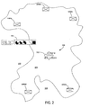
- FIG. 3 shows the graphical display of FIG. 2 in which a desired effect has been assigned to a target.
- FIG. 4 show the graphical display of FIG. 3 in which strike asset recommendations are presented to a user.
- FIG. 5 shows the graphical display of FIG. 4 in which a target has been assigned sufficient strike asset assets to meet the desired effect.
- FIG. 6 shows the graphical display of FIG. 5 in which battle damage assessment is shown for the target.
- FIGS. 7A-7F show a target icon with a plurality of different graphical elements to communicate different status conditions to a user.
- FIG. 8 shows alternative graphical elements displayed with a target icon to represent different desired effects.
- FIGS. 9A-9C show various graphic elements which can be displayed with a target icon in various different states of mission planning, execution, and evaluation.
- FIGS. 10A-10H show various a strike asset icon displayed with various alternative graphic elements.
- FIG. 11A-11H show association lines used during a fire control planning stage and having various different styles to indicate different strike asset associations.
- FIG. 12A-12F show various alternative graphical elements which can be displayed in conjunction with a target icon to indicate specific fire control commands communicated to a strike asset.
- FIG. 13A-13B show two possible graphics for coordinating adjusting rounds.
- FIG. 14A-14E show association lines in combination with various alternative graphical elements used during a fire control execution stage to communicate information to a user.
- FIG. 15A-15H show various different graphical elements that can be displayed in conjunction with a target icon to indicate a battle damage assessment.
- FIG. 16 is an example of a computer system that can be used to implement the present invention.
- FIG. 17 is an example of a general purpose computer that can be used for implementing the computer system in FIG. 16 .
- FIG. 18 is a flowchart that is useful for understanding the present invention.
- the present invention concerns methods and systems which bring the fire support coordination and control process to the small unit level.
- the inventive arrangements provide a simple, integrated user interface that provides full fires functionality without the complexity of conventional fire support coordination systems.
- the integrated user interface provides small units with greater visibility and clarity of the fire mission data, on-map visualization of targets, recommended fire support assets for various targets, identifies mission conflicts, and provides real time status of involved entities.
- users can approve fire missions, check fire, repeat missions, and end missions.
- the system offers small units automatic weapon pairing, auto-validation of logistics, command clearances, de-confliction, and range to target information. Automatic checks and feedback systems result in user-defined fire missions that avoid the usual communications with FSCCs, and rapid access to battle damage assessments (BDA).
- BDA battle damage assessments
- FIG. 1 there is provided a drawing which shows the content of a computer generated image or display that is presented to a user.
- the displayed image is a geographical representation of a battle space in the form of a map 100.
- the computer system used to generate the display is described below in further detail.
- a computer generated map display can include various details relating to the subject of a particular geographical area including land mass areas 106, water features 108, terrain, roads, topography, vegetation and so on. For greater clarity, some of these various details are omitted from the image 100 in FIG. 1 and in similar figures throughout this specification.
- a tool bar 101 can be provided for fast and convenient selection of computer-based functions that allow fire missions to be planned, controlled, executed and evaluated according to the various embodiments of the present invention.
- tool bar 101 and various other functions of the fire control system are described in greater detail below, however these functions are preferably accessed with simple point and click commands.
- point and click means the positioning of a cursor over a computer icon, and signaling the computer system by suitable means, such as a control switch.
- suitable means such as a control switch.
- users can input such commands to the computer system by well known means such as a computer mouse, touch pad, keyboard or any other type pointing device.
- the invention is not limited in this regard and any other suitable method can be used to access the functions of the system.
- the functions of the tool bar can be context sensitive so that the options available to the user will vary in accordance with the fire control planning and execution process.
- the targeting process can begin with the user clicking on a "target” button on the tool bar 101, and can then click a location on the map.
- the "target” button can be identified by text or preferably by an icon.
- the system response can vary depending on the location that is clicked. If the click spot is a target icon, the system will create a new mission for the existing target. If the click spot is an enemy unit, the system will create a new target and mission based on the characteristics of the selected object with regard to target type and size. If the click spot is neither of the above, a new target will be created within the system, but will not create an associated mission.
- a target 700 can be selected for a fire mission by a point and click method. Specifically, a user can position a cursor (not shown) over a particular map location (e.g., target icon 700) and select the target icon by means of a user input signal, such as activation of a control switch. Once selected, the appearance of the target icon is modified or highlighted. For example, in FIG. 2 , the target icon 700 is shown to be modified by displaying a graphic element 702 with the target icon. Once the target has been selected, all subsequent fire related operations are directed to that particular target. When a target is selected, the system will enable context sensitive toolbar 101 with a suitable set of actions in a fires button toolbar. If a target has been previously selected that causes any form of state changes, the process will return to the exact state it was in prior to losing selection.
- the user can initiate a user input to specify a desired effect upon the target. For example, the user may specify that the selected target be suppressed, neutralized, or destroyed. Each selection will automatically replace any previous selection.
- the appearance of the target icon 700 is preferably modified as shown in FIG. 3 to include a graphic element 706.
- Various different graphic elements can be provided to identify different types of desired effects. For example, various desired effects can be indicated using the graphic elements shown in FIG. 8 .
- the graphic element 706a indicates that the target element is to be suppressed; graphic element 706b indicates that the target element is to be neutralized, and graphic element 706c indicates that the target element is to be destroyed.
- the selected graphic element 706 indicates that the desired effect is to destroy the target.
- FIG. 4 shows one example of how map 100 could appear as the user is working with the system in the WPT state.
- the system will visually identify which strike assets that are capable or not capable of operation by adding an appropriate graphic element to a particular strike asset icon.
- visual indications of strike assets that are not available can be provided by using one or more of the graphic elements shown in FIG. 10E-10H .
- the icons associated with strike asset 1000a and 1000e have been modified with graphic elements 1010 and 1014 to indicate that these strike assets are not available.
- the meanings of the various other graphic elements used with strike asset icons are shown in FIGs. 10A-10H .
- association lines 401a-401d can also be added to the map to provide additional information that is useful for mission planning.
- the available association lines and their meanings are shown in FIGS. 11A-11H .
- the solid lines (401 a, 401 d, 40 1 e) indicate that a strike asset weapon is direct fire, line of sight (LOS), whereas the broken lines (401b, 40 1 c) indicate that a strike asset weapon is indirect fire (non LOS) and capable of firing.
- Various other association lines can be used as shown in FIGS. 11B-11H .
- a user can select a plurality of strike assets which are to be used against a selected target by clicking on the selected strike assets. If a strike asset has been previously selected and the user clicks on the asset, the association will be removed, and the displayed visualization of the strike asset will revert to what was previously calculated with regard to strike asset capability and usability.
- the user can select an Auto WTP button which enables the system to automatically evaluate the information it has concerning the type and size of the selected target. Based on this stored information, the system automatically recommends pairings of strike assets.
- strike assets 1000b, 1000c are modified with graphical elements 1004b, 1004c to indicate that they are system recommended based on an Auto WTP function. Once the Auto WTP function is complete, the user will be able to edit all existing pairings and assignments of strike assets by either selecting the particular strike asset icon or the association line (discussed below).
- target icon 700 is modified with the addition of a graphic element 902.
- Graphic element 902 can be an outline of a circle or pie graphic to indicate that the target pairing process has been started, but no assets have yet been assigned.
- the pie chart graphic in the center of the target icon can change to represent the percentage of strike asset assignment versus the desired effect.
- graphic 904 shows that the percentage of strike asset assignment is approximately 75%.
- graphic 906 can be used to indicate the strike asset assignment is 100%.
- the user can select any association between a target and a strike asset.
- these associations can include one basic shot, two basic shots, or three basic shots from the selected strike unit.
- the system automatically recalculates and displays the ratio of selected effects versus desired effects.
- the system can also display the number of munitions by changing the appearance of the association line, and/or by displaying the number of munitions selected at the strike asset end of the association line.
- Various association lines that can be used for this purpose are shown in FIGs. 11B-11C and 11E-11H . If the user selects a number of basic shots which will result in exceeding the desired effect, a suitable visual indication can be provided. For example, the number of rounds can be displayed in an different scheme, indicating that the number of shots or rounds can be reduced.
- Additional information can be graphically communicated to the user by color coding the association lines and graphical elements added to the strike assets.
- the condition of strike asset 1000a is such that it cannot fire, so the association line 401a and graphical element 1014 can be displayed in the color red.
- the strike assets 1000b and 1000c can be system recommended strike assets for the specified mission in accordance with an Auto WTP process, so the association line 401 b, 401c and graphical elements 1004b, 1004c can be displayed in green.
- the strike assets 1000d, 1000e can be "not recommended" by the computer system, and so their association lines 401 d, 401e and graphic elements 1002, 1010 can be displayed in yellow.
- a user has the option of selecting various types of control methods and assigning this control method to the strike asset.
- these control methods can include directions to fire an adjusting round, fire at the user's command, fire for effect, and to fire when ready.
- Each of the various control options can be made available to the user through the toolbar 101. This operation can performed at any time during the weapon target pairing phase, which terminates when the mission is "sent" to the strike assets.
- Various graphic elements 1202, 1204, 1206, 1208, 1402, 1404 that can be used for control (and their associated meaning) are illustrated in FIGs. 12A-12D and FIGs. 14A-14B respectively. Once the mission is sent, it cannot be changed.
- the particular control method selected by the user can be indicated with one or more graphic element that can be displayed on the association line, on the target, or elsewhere.
- Various graphic elements 1202, 1204, 1206, 1208, 1402, 1404 that can be used for control (and their associated meaning) are illustrated in FIGs. 12A-12D and FIGs. 14A-14B respectively.
- the graphic elements 1206, 1404b, 1404c indicate that the mission has been sent to the respective strike assets, and that they have been ordered to fire for effect.
- Other command conditions can also exist and be illustrated in a similar manner without limitation.
- the target can be handed off to a higher level command by pressing a "call for fire” button on the toolbar 101.
- the target icon can be modified as shown in FIG. 12F .
- the target can be assigned to another unit by selecting the unit from the map, and pressing the "target handoff" button. If a user has been assigned a target by another unit, then the target icon 700 on his map will be modified as illustrated in FIG. 12E .
- the user can select the "send mission” button from the toolbar 101. This action causes the system to transmit the assignment and shot count to the designated strike assets. If there are any strike assets which are part of the fire solution that are in a conflict state, the "send mission” command will override the conflict. Notably, the "send mission” command cannot be undone. The mission at this point will be completed by the strike units unless the user sends a new command to cancel. Activating the "send mission” button will deactivate all previous states described herein and allow the user to begin a new set of operations.
- buttons on the toolbar can include the "abort" and “check fire” buttons.
- the abort button will terminate or cancel the mission.
- the "check fire” button will temporarily suspend firing operations. As shown in FIG. 5 , the association lines for the firing solution will indicate that the mission as displayed has been sent to the proper strike units.
- the "adjust" button will be activated in the toolbar 101. Thereafter, when the adjust button is selected by a user, an adjust graphic can be presented or displayed to the user.
- Example of an adjust graphic 1302 is shown in FIG. 13A .
- the adjust graphic 1302 can be displayed as an overlay centered on the location of the target 700, but the invention is not limited in this regard.
- the adjust display allows a user to communicate information to a strike unit regarding the actual observed placement of rounds in the vicinity of the target. Such information can be used by the strike unit to adjust equipment and thereby place the rounds more directly on target.
- Each ring in graphic 1302 provides a reference distance to the target. The user selects where the round landed by clicking within the graphic.
- the system responds by marking the adjustment location with graphic element 1304, automatically calculating the proper correction, and enabling the "send adjustment” button. Thereafter, the user can click on the "send adjustment” button to automatically communicate the adjustment to the appropriate strike unit. Any click on the display screen outside the adjust graphic removes the previously identified adjustment location, and disables the "send adjustment” button. Once the adjustment location has been marked in this way, the user can press the Fire For Effect button on the toolbar, or perform another adjusting round. In some instances, a vertical adjustment of round placement may be required, in which case the graphic element in FIG. 13B can be used.
- the battle damage assessment buttons in the toolbar will become active after all designated strike units have completed their assigned mission, and have clicked on a "rounds completed” button.
- the battle damage assessment buttons can include various buttons to allow the user to indicate the results of the fire mission. For example, separate BDA buttons can be provided to indicate that the target was suppressed, neutralized, or destroyed. Thereafter, the user can click on a "send BDA" button which communicates the BDA to other users on the system, and updates the system display to include an appropriate BDA graphic. For example, as shown in FIG.
- the target icon can be modified to add a graphical element 708 which serves as a battle damage assessment indicator.
- a variety of different battle damage assessments are available using different graphic elements as shown in FIG. 15A-15H , where each graphic element has a defined meaning as shown.
- FIGS. 15B-15D can indicate desired effect for missions that were met (successful).
- the graphics in FIGS. 15E-15H indicate that a mission was not met.
- the outline of the graphic in each case is filled in to an extent to show the actual results achieved.
- FIG. 15H shows the case where a mission was to destroy, but the effect actually achieved was merely suppression.
- the user can press an "end of mission” button at any time. Prior to sending the mission to the strike units, activation of the "end of mission” button will have the effect of clearing all mission states and removing any assignments. After sending the mission to the strike units, but prior to completion of the mission, it will generate a "check fire” message. After all rounds are complete, activating the "end of mission” button will end the mission. The user can press an “abort” button at any time. This action will immediately send a check fire notification to the strike units under circumstances where the mission has already been sent but the system has not been notified that all rounds have been fired.
- FIGS. 7A-7F there are shown various exemplary graphic elements that can be displayed with a target icon 700 to communicate different status conditions to a user.
- FIG. 7A shows a target icon 700 as a standard 2525b target representation.
- FIG. 7B shows the target icon 700 with a graphical element 702 added to indicate a user selection of that target, and assigning all actions (e.g., button selection) to the selected target object.
- FIG. 7C the standard target icon 700 is shown with a graphic element 704 added to indicate that the target is in a conflicted state due to rules of engagement, such as may occur when the target is within a no-fire-area (NFA).
- NFA no-fire-area
- the standard target icon is shown with a graphic element 706 added to specify a desired effect upon the target.
- the standard target icon 700 is shown with an additional graphic element in the center of the target icon to indicate that the target has been assigned enough assets to meet the desired effect. The icon in FIG. 7E thus indicates that the mission can now be executed.
- the standard target icon 700 is shown with a graphic element 708 added to specify a battle damage assessment.
- FIGS. 9A-9C there are shown several exemplary graphic elements which can be displayed with a target icon 700 in different states of mission planning, execution, and evaluation.
- the target icon 700 with desired effect representation (graphic element 706) is shown in the planned state.
- graphic element 902 is added to specify an "in progress" state which occurs when certain assets are selected and associated with the target.
- FIG. 9C two exemplary target icons 700 are shown, one having a graphic element 904, and a second having a 906 can indicate the percentage of asset assignments versus the desired effect.
- the circle in the center of the target icon will be solid as shown.
- FIGS. 10A-10H there is shown a strike asset icon displayed with various alternative graphic elements.
- the basic icon used to represent a strike asset 1000 (sometimes referred to as a fire support unit) is shown in FIG. 10A .
- the strike asset icon 1000 is shown with a graphic element 1002 used to indicate that the strike asset is a user selection that forms part of the fire solution.
- the strike asset icon 1000 is shown with a graphic element 1004, which indicates that the strike asset is system recommended based on an automated WTP process.
- FIG. 10D the strike asset icon 1000 is shown with a graphic element 1006, which indicates a user selected strike asset that is conflicted, where the user has over-ridden the conflict.
- FIG. 10A The basic icon used to represent a strike asset 1000 (sometimes referred to as a fire support unit) is shown in FIG. 10A .
- the strike asset icon 1000 is shown with a graphic element 1002 used to indicate that the strike asset is a user selection that forms part of the fire solution.
- the strike asset icon 1000 is shown with
- the strike asset icon 1000 is shown with a graphic element 1008, which indicates that the strike asset has denied the mission or cannot comply with the requested mission.
- the strike asset icon 1000 is shown with a graphic element 1010, which indicates that the strike asset is available, though not recommended by an automated WTP process.
- the strike asset icon 1000 is shown with a graphic element 1012, which indicates that the strike asset is available, but has a conflict.
- the strike asset icon 1000 is shown with a graphic element 1014, which indicates a user selected strike asset that is unavailable.
- the present invention can be realized in one computer system. Alternatively, the present invention can be realized in several interconnected computer systems. Any kind of computer system or other apparatus adapted for carrying out the methods described herein is suited.
- a typical combination of hardware and software for each user computer can be a general-purpose computer system.
- the general-purpose computer system can have a computer program that can control the computer system such that it carries out the methods described herein.
- the present invention can take the form of a computer program product on a computer-usable storage medium (for example, a hard disk or a CD-ROM).
- the computer-usable storage medium can have computer-usable program code embodied in the medium.
- the term computer program product refers to a device comprised of all the features enabling the implementation of the methods described herein.
- Computer program, software application, computer software routine, and/or other variants of these terms in the present context, mean any expression, in any language, code, or notation, of a set of instructions intended to cause a system having an information processing capability to perform a particular function either directly or after either or both of the following: a) conversion to another language, code, or notation; or b) reproduction in a different material form.
- a computer system in accordance with the present invention can comprise various types of computing systems and devices, including a server computer, a client user computer, a personal computer (PC), a tablet PC, a laptop computer, a desktop computer, a control system, a network router, switch or bridge, or any other device capable of executing a set of instructions (sequential or otherwise) that specifies actions to be taken by that device.
- a device of the present disclosure also includes any electronic device that provides voice, video or data communication.
- FIG. 16 shows an interconnected computer system comprising a plurality of separate user computers 1604 which are connected to a server 1602 by means of a computer network 1606.
- the network connection can be wired, wireless, or a combination of the two.
- the software for carrying out the various functions described herein can be disposed on the server 1602, the user computers 1604, or a combination of the two.
- data stores necessary to support the various operations described herein can be provided on server 1602, one or more user computers 1604, or on a combination of these.
- the phrase "computer system" shall be understood to include any collection of computing devices that individually or jointly execute a set (or multiple sets) of instructions to perform any one or more of the methodologies discussed herein.
- a server computer 1602 and/or a client user computer 1604 can be arranged as shown with regard to FIG. 17 which shows a general purpose computer.
- the general purpose computer 1700 includes a processor 1702 (such as a central processing unit (CPU), a graphics processing unit (GPU, or both), a main memory 1704 and a static memory 1706, which communicate with each other via a bus 1708.
- the computer system 1700 can further include a display unit 1710, such as a video display (e.g., a liquid crystal display or LCD), a flat panel, a solid state display, or a cathode ray tube (CRT)).
- a video display e.g., a liquid crystal display or LCD
- flat panel e.g., a flat panel
- solid state display e.g., a solid state display
- CRT cathode ray tube
- the computer system 1700 can include an input device 1712 (e.g., a keyboard), a cursor control device 1714 (e.g., a mouse), a disk drive unit 1716, a signal generation device 1718 (e.g., a speaker or remote control) and a network interface device 1720.
- an input device 1712 e.g., a keyboard
- a cursor control device 1714 e.g., a mouse
- a disk drive unit 1716 e.g., a disk drive unit 1716
- a signal generation device 1718 e.g., a speaker or remote control
- the disk drive unit 1716 includes a computer-readable storage medium 1722 on which is stored one or more sets of instructions 1724 (e.g., software code) configured to implement one or more of the methodologies, procedures, or functions described herein.
- the instructions 1724 can also reside, completely or at least partially, within the main memory 1704, the static memory 1706, and/or within the processor 1702 during execution thereof by the computer system 1700.
- the main memory 1704 and the processor 1702 also can constitute machine-readable media.
- Dedicated hardware implementations including, but not limited to, application-specific integrated circuits, programmable logic arrays, and other hardware devices can likewise be constructed to implement the methods described herein.
- Applications that can include the apparatus and systems of various embodiments broadly include a variety of electronic and computer systems. Some embodiments implement functions in two or more specific interconnected hardware modules or devices with related control and data signals communicated between and through the modules, or as portions of an application-specific integrated circuit.
- the exemplary system is applicable to software, firmware, and hardware implementations.
- the methods described above are stored as software programs in a computer-readable storage medium and are configured for running on a computer processor.
- software implementations can include, but are not limited to, distributed processing, component/object distributed processing, parallel processing, virtual machine processing, which can also be constructed to implement the methods described herein.
- a network interface device 1720 connected to a network environment 1726 communicates over the network 1726 using the instructions 1724.
- the instructions 1724 can further be transmitted or received over a network 1726 via the network interface device 1720.
- While the computer-readable storage medium 1722 is shown in an exemplary embodiment to be a single storage medium, the term “computer-readable storage medium” should be taken to include a single medium or multiple media (e.g., a centralized or distributed database, and/or associated caches and servers) that store the one or more sets of instructions.
- the term “computer-readable storage medium” shall also be taken to include any medium that is capable of storing, encoding or carrying a set of instructions for execution by the machine and that cause the machine to perform any one or more of the methodologies of the present disclosure.
- computer-readable medium shall accordingly be taken to include, but not be limited to, solid-state memories such as a memory card or other package that houses one or more read-only (non-volatile) memories, random access memories, or other re-writable (volatile) memories; magneto-optical or optical medium such as a disk or tape; as well as carrier wave signals such as a signal embodying computer instructions in a transmission medium; and/or a digital file attachment to e-mail or other self-contained information archive or set of archives considered to be a distribution medium equivalent to a tangible storage medium. Accordingly, the disclosure is considered to include any one or more of a computer-readable medium or a distribution medium, as listed herein and to include recognized equivalents and successor media, in which the software implementations herein are stored.
- FIG. 17 is one possible example of a general purpose computer that can be used to implement the computer system 1600 described herein.
- the invention is not limited in this regard and any other suitable computer system architecture can also be used without limitation.
Abstract
Description
- The inventive arrangements relate to fire control systems, and more particularly to fire control systems which are suitable for small unit operations.
- Fire support refers to weapons fire used to engage enemy forces and facilities. Fire support coordination is the planning and executing of weapons fire (fires) using a suitable weapon or group of weapons. Effective fire support ensures that a suitable attack means is delivered on the correct target at the desired time. Fire support planning and coordination in the ground combat area is a very complex task involving continuous analysis enemy and friendly forces positions; identifying targets; identifying and assigning fire support assets; scheduling delivery of munitions.
- Fire support planning and coordination is generally the responsibility of a fire support coordination center (FSCC). The FSCC is a centralized communications facility and its associated personnel who coordinate various forms of fire support. From an organizational standpoint, an FSCC usually exists in military units at one or more relatively high organizational levels. For example, an FSCC can be provided for each of a division, brigade, and battalion level. An FSCC is not generally established at the company level. The company commander is responsible for his fires and organizes his personnel accordingly. The lowest level FSCC that has the ability to handle a particular mission will generally provide the necessary fire support.
- Within each FSCC, there is a fire support coordinator (FSC) who is responsible to manage the activities of the FSCC. The FSC makes decisions regarding assets needed for covering various targets, and requests additional support from higher level echelons if his assets are inadequate. When evaluating requests from lower echelons for fires, the FSC considers the type and significance of the target, the available time to engage the target, which assets are available for proceeding with the attack, the objectives that are to be achieved with respect to the particular target, and the minimum number/type of assets to carry out the attack. The FSC must also consider whether an attack upon a particular target will present a risk of fratricide, and may take appropriate steps to minimize risk to friendly units. Another consideration for the FSC is the allocation and availability of ammunition within a strike asset. In those instances where one strike asset lacks sufficient ammunition to engage a target, it may be desirable to make use of alternative units. Once these issues have been resolved, the FSC will communicate the request for fire support to the appropriate supporting unit (artillery units, mortar units, naval or air support) that can safely and effectively deliver the needed fires.
- A substantial portion of the coordination tasks required to execute a fire support plan are accomplished at the battalion level. Battalion FSCCs monitor/receive calls for fire and air requests from the companies that they supervise. These tasks are normally performed by the appropriate supporting unit representatives (e.g., artillery, air operations, or mortar representative). Supporting unit representatives assist the FSC in performing the tasks required to coordinate and clear fire support missions.
- The invention concerns a computer system and method for providing fire support command and control for small unit operations. The method involves displaying a geographical representation of a battle space using a map. One or more strike asset icons are displayed on the map, each representing strike assets which are geographically dispersed within the battle space. At least one target icon is also displayed on the map to represent a target within the battle space.
- In response to a user input identifying a desired effect upon the target, the system graphically conveys fire mission planning information to the user during an interactive mission planning process. It conveys this information by selectively displaying one or more graphic elements, each having a predetermined meaning, in combination with a target icon. It can also convey this information by displaying one or more graphic elements, each having a predefined meaning, in combination with at least one strike asset icon. The method can also include conveying mission planning information to the user during the mission planning process by selectively displaying one of a plurality of line styles for an association line extending between a target icon and the strike asset icon. The method further involves automatically determining if a proposed fire solution will result in any conflicts or errors. In response to a user command, mission data for implementing a fire mission is automatically communicated to the assigned strike assets.
- Subsequent to the communicating step, a status of at least one strike asset is conveyed to the user by selectively displaying one or more graphic elements, each having a predetermined meaning, in combination with the strike asset icon. The method can also include graphically conveying a battle damage assessment to the user during or after the fire mission by selectively displaying one or more graphic elements, each having a predetermined meaning, in combination with the target icon.
- Embodiments will be described with reference to the following drawing figures, in which like numerals represent like items throughout the figures, and in which:
-
FIG. 1 is a drawing which shows a computer generated graphical display of a battle space which includes target icons and strike asset icons. -
FIG. 2 shows the graphical display ofFIG. 1 in which a target has been selected for some action. -
FIG. 3 shows the graphical display ofFIG. 2 in which a desired effect has been assigned to a target. -
FIG. 4 show the graphical display ofFIG. 3 in which strike asset recommendations are presented to a user. -
FIG. 5 shows the graphical display ofFIG. 4 in which a target has been assigned sufficient strike asset assets to meet the desired effect. -
FIG. 6 shows the graphical display ofFIG. 5 in which battle damage assessment is shown for the target. -
FIGS. 7A-7F show a target icon with a plurality of different graphical elements to communicate different status conditions to a user. -
FIG. 8 shows alternative graphical elements displayed with a target icon to represent different desired effects. -
FIGS. 9A-9C show various graphic elements which can be displayed with a target icon in various different states of mission planning, execution, and evaluation. -
FIGS. 10A-10H show various a strike asset icon displayed with various alternative graphic elements. -
FIG. 11A-11H show association lines used during a fire control planning stage and having various different styles to indicate different strike asset associations. -
FIG. 12A-12F show various alternative graphical elements which can be displayed in conjunction with a target icon to indicate specific fire control commands communicated to a strike asset. -
FIG. 13A-13B show two possible graphics for coordinating adjusting rounds. -
FIG. 14A-14E show association lines in combination with various alternative graphical elements used during a fire control execution stage to communicate information to a user. -
FIG. 15A-15H show various different graphical elements that can be displayed in conjunction with a target icon to indicate a battle damage assessment. -
FIG. 16 is an example of a computer system that can be used to implement the present invention. -
FIG. 17 is an example of a general purpose computer that can be used for implementing the computer system inFIG. 16 . -
FIG. 18 is a flowchart that is useful for understanding the present invention. - The invention is described with reference to the attached figures. The figures are not drawn to scale and they are provided merely to illustrate the instant invention. Several aspects of the invention are described below with reference to example applications for illustration. It should be understood that numerous specific details, relationships, and methods are set forth to provide a full understanding of the invention. One having ordinary skill in the relevant art, however, will readily recognize that the invention can be practiced without one or more of the specific details or with other methods. In other instances, well-known structures or operation are not shown in detail to avoid obscuring the invention. The invention is not limited by the illustrated ordering of acts or events, as some acts may occur in different orders and/or concurrently with other acts or events. Furthermore, not all illustrated acts or events are required to implement a methodology in accordance with the invention.
- Conventional fire support coordination and control methods are complicated and cumbersome. Advanced training is required for fire support coordinators (FSCs) and fire support personnel at the division, brigade and battalion level to support these conventional systems. The methods make use of multiple spreadsheets, forms, and checklists, for purposes of responding to requests for fires from personnel at the company level and below; even so, these systems are prone to errors. Consequently, these methods are not suitable for use by small military units (e.g., company level and below). Instead, such small units must rely on fire support coordination centers (FSCCs) at higher levels, such as at the battalion or brigade level.
- The present invention concerns methods and systems which bring the fire support coordination and control process to the small unit level. The inventive arrangements provide a simple, integrated user interface that provides full fires functionality without the complexity of conventional fire support coordination systems. The integrated user interface provides small units with greater visibility and clarity of the fire mission data, on-map visualization of targets, recommended fire support assets for various targets, identifies mission conflicts, and provides real time status of involved entities. With a simple point and click interface, users can approve fire missions, check fire, repeat missions, and end missions. The system offers small units automatic weapon pairing, auto-validation of logistics, command clearances, de-confliction, and range to target information. Automatic checks and feedback systems result in user-defined fire missions that avoid the usual communications with FSCCs, and rapid access to battle damage assessments (BDA).
- Referring now to
FIG. 1 there is provided a drawing which shows the content of a computer generated image or display that is presented to a user. The displayed image is a geographical representation of a battle space in the form of amap 100. The computer system used to generate the display is described below in further detail. As is well known in the art, a computer generated map display can include various details relating to the subject of a particular geographical area includingland mass areas 106, water features 108, terrain, roads, topography, vegetation and so on. For greater clarity, some of these various details are omitted from theimage 100 inFIG. 1 and in similar figures throughout this specification. - Displayed on the
map 100 are one or more computer generated target symbols oricons 700 which represent one or more targets within the battle space. Fire missions can be directed against the targets using one or more geographically dispersed strike assets. The strike assets are represented on themap 100 asstrike asset icons 1000. For simplicity in distinguishing the various fire support icons, they are identified as 1000a-1000e. Atool bar 101 can be provided for fast and convenient selection of computer-based functions that allow fire missions to be planned, controlled, executed and evaluated according to the various embodiments of the present invention. - The functions of
tool bar 101 and various other functions of the fire control system are described in greater detail below, however these functions are preferably accessed with simple point and click commands. As used herein, point and click means the positioning of a cursor over a computer icon, and signaling the computer system by suitable means, such as a control switch. For example, users can input such commands to the computer system by well known means such as a computer mouse, touch pad, keyboard or any other type pointing device. Still, the invention is not limited in this regard and any other suitable method can be used to access the functions of the system. The functions of the tool bar can be context sensitive so that the options available to the user will vary in accordance with the fire control planning and execution process. - The targeting process can begin with the user clicking on a "target" button on the
tool bar 101, and can then click a location on the map. The "target" button can be identified by text or preferably by an icon. When the user clicks on the map, the system response can vary depending on the location that is clicked. If the click spot is a target icon, the system will create a new mission for the existing target. If the click spot is an enemy unit, the system will create a new target and mission based on the characteristics of the selected object with regard to target type and size. If the click spot is neither of the above, a new target will be created within the system, but will not create an associated mission. - Referring now to
FIG. 2 , atarget 700 can be selected for a fire mission by a point and click method. Specifically, a user can position a cursor (not shown) over a particular map location (e.g., target icon 700) and select the target icon by means of a user input signal, such as activation of a control switch. Once selected, the appearance of the target icon is modified or highlighted. For example, inFIG. 2 , thetarget icon 700 is shown to be modified by displaying agraphic element 702 with the target icon. Once the target has been selected, all subsequent fire related operations are directed to that particular target. When a target is selected, the system will enable contextsensitive toolbar 101 with a suitable set of actions in a fires button toolbar. If a target has been previously selected that causes any form of state changes, the process will return to the exact state it was in prior to losing selection. - Once the target is selected, the user can initiate a user input to specify a desired effect upon the target. For example, the user may specify that the selected target be suppressed, neutralized, or destroyed. Each selection will automatically replace any previous selection. Once the desired effect is specified, the appearance of the
target icon 700 is preferably modified as shown inFIG. 3 to include agraphic element 706. Various different graphic elements can be provided to identify different types of desired effects. For example, various desired effects can be indicated using the graphic elements shown inFIG. 8 . Thegraphic element 706a indicates that the target element is to be suppressed;graphic element 706b indicates that the target element is to be neutralized, andgraphic element 706c indicates that the target element is to be destroyed. InFIG. 3 , the selectedgraphic element 706 indicates that the desired effect is to destroy the target. - Once a target has been selected and the desired effect specified, a user can initiate a weapon target pairing (WTP) state. This state can be accessed by a suitable button provided in the
toolbar 101. In general, a target must be selected to enable the WTP button in the toolbar. When the WTP state is selected, the appearance of the display can be modified.FIG. 4 shows one example of howmap 100 could appear as the user is working with the system in the WPT state. The system will visually identify which strike assets that are capable or not capable of operation by adding an appropriate graphic element to a particular strike asset icon. For example, visual indications of strike assets that are not available can be provided by using one or more of the graphic elements shown inFIG. 10E-10H . In the example shown inFIG. 4 , the icons associated withstrike asset graphic elements FIGs. 10A-10H . - In the WTP state,
association lines 401a-401d can also be added to the map to provide additional information that is useful for mission planning. The available association lines and their meanings are shown inFIGS. 11A-11H . In the example shown inFIG. 4 , the solid lines (401 a, 401 d, 40 1 e) indicate that a strike asset weapon is direct fire, line of sight (LOS), whereas the broken lines (401b, 40 1 c) indicate that a strike asset weapon is indirect fire (non LOS) and capable of firing. Various other association lines can be used as shown inFIGS. 11B-11H . - In the WTP state, a user can select a plurality of strike assets which are to be used against a selected target by clicking on the selected strike assets. If a strike asset has been previously selected and the user clicks on the asset, the association will be removed, and the displayed visualization of the strike asset will revert to what was previously calculated with regard to strike asset capability and usability. Alternatively, the user can select an Auto WTP button which enables the system to automatically evaluate the information it has concerning the type and size of the selected target. Based on this stored information, the system automatically recommends pairings of strike assets. In
FIG. 4 ,strike assets graphical elements - While in the WTP state, the system will modify the appearance of the target icon to visually indicate the ratio of assigned effects (based on strike units selected) versus desired effects. In the example shown in
FIG. 4 ,target icon 700 is modified with the addition of agraphic element 902.Graphic element 902 can be an outline of a circle or pie graphic to indicate that the target pairing process has been started, but no assets have yet been assigned. As depicted inFIG. 9C the pie chart graphic in the center of the target icon can change to represent the percentage of strike asset assignment versus the desired effect. For example, graphic 904 shows that the percentage of strike asset assignment is approximately 75%. When enough strike assets have been associated with the particular target to achieve the desired effect, graphic 906 can be used to indicate the strike asset assignment is 100%. - The user can select any association between a target and a strike asset. For example, these associations can include one basic shot, two basic shots, or three basic shots from the selected strike unit. With each selection, the system automatically recalculates and displays the ratio of selected effects versus desired effects. The system can also display the number of munitions by changing the appearance of the association line, and/or by displaying the number of munitions selected at the strike asset end of the association line. Various association lines that can be used for this purpose are shown in
FIGs. 11B-11C and 11E-11H . If the user selects a number of basic shots which will result in exceeding the desired effect, a suitable visual indication can be provided. For example, the number of rounds can be displayed in an different scheme, indicating that the number of shots or rounds can be reduced. - Additional information can be graphically communicated to the user by color coding the association lines and graphical elements added to the strike assets. For example, the condition of
strike asset 1000a is such that it cannot fire, so theassociation line 401a andgraphical element 1014 can be displayed in the color red. Thestrike assets association line graphical elements strike assets association lines graphic elements - A user has the option of selecting various types of control methods and assigning this control method to the strike asset. For example, these control methods can include directions to fire an adjusting round, fire at the user's command, fire for effect, and to fire when ready. Each of the various control options can be made available to the user through the
toolbar 101. This operation can performed at any time during the weapon target pairing phase, which terminates when the mission is "sent" to the strike assets. Variousgraphic elements FIGs. 12A-12D andFIGs. 14A-14B respectively. Once the mission is sent, it cannot be changed. The particular control method selected by the user can be indicated with one or more graphic element that can be displayed on the association line, on the target, or elsewhere. Variousgraphic elements FIGs. 12A-12D andFIGs. 14A-14B respectively. InFIG. 5 , thegraphic elements - At any time prior to mission being sent to the strike assets, the target can be handed off to a higher level command by pressing a "call for fire" button on the
toolbar 101. When this occurs, the target icon can be modified as shown inFIG. 12F . Alternatively, the target can be assigned to another unit by selecting the unit from the map, and pressing the "target handoff" button. If a user has been assigned a target by another unit, then thetarget icon 700 on his map will be modified as illustrated inFIG. 12E . - When all mission planning is completed, the user can select the "send mission" button from the
toolbar 101. This action causes the system to transmit the assignment and shot count to the designated strike assets. If there are any strike assets which are part of the fire solution that are in a conflict state, the "send mission" command will override the conflict. Notably, the "send mission" command cannot be undone. The mission at this point will be completed by the strike units unless the user sends a new command to cancel. Activating the "send mission" button will deactivate all previous states described herein and allow the user to begin a new set of operations. - After the mission has been sent, various toolbar buttons will be activated. For example, a user can assign various control methods or directions to a strike asset, such as directions to fire an adjusting round, fire at the user's command, fire for effect, and to fire when ready. See
FIGs. 12A-12D andFIGs. 14A-14B . Activated buttons on the toolbar can include the "abort" and "check fire" buttons. The abort button will terminate or cancel the mission. The "check fire" button will temporarily suspend firing operations. As shown inFIG. 5 , the association lines for the firing solution will indicate that the mission as displayed has been sent to the proper strike units. - If the target control was designated to fire an adjusting round, the "adjust" button will be activated in the
toolbar 101. Thereafter, when the adjust button is selected by a user, an adjust graphic can be presented or displayed to the user. Example of an adjust graphic 1302 is shown inFIG. 13A . In some embodiments, the adjust graphic 1302 can be displayed as an overlay centered on the location of thetarget 700, but the invention is not limited in this regard. The adjust display allows a user to communicate information to a strike unit regarding the actual observed placement of rounds in the vicinity of the target. Such information can be used by the strike unit to adjust equipment and thereby place the rounds more directly on target. Each ring in graphic 1302 provides a reference distance to the target. The user selects where the round landed by clicking within the graphic. The system responds by marking the adjustment location withgraphic element 1304, automatically calculating the proper correction, and enabling the "send adjustment" button. Thereafter, the user can click on the "send adjustment" button to automatically communicate the adjustment to the appropriate strike unit. Any click on the display screen outside the adjust graphic removes the previously identified adjustment location, and disables the "send adjustment" button. Once the adjustment location has been marked in this way, the user can press the Fire For Effect button on the toolbar, or perform another adjusting round. In some instances, a vertical adjustment of round placement may be required, in which case the graphic element inFIG. 13B can be used. - After the mission is completed, the actual effects upon the target can be graphically communicated to the user. In a preferred embodiment, the battle damage assessment (BDA) buttons in the toolbar will become active after all designated strike units have completed their assigned mission, and have clicked on a "rounds completed" button. The battle damage assessment buttons can include various buttons to allow the user to indicate the results of the fire mission. For example, separate BDA buttons can be provided to indicate that the target was suppressed, neutralized, or destroyed. Thereafter, the user can click on a "send BDA" button which communicates the BDA to other users on the system, and updates the system display to include an appropriate BDA graphic. For example, as shown in
FIG. 6 , the target icon can be modified to add agraphical element 708 which serves as a battle damage assessment indicator. A variety of different battle damage assessments are available using different graphic elements as shown inFIG. 15A-15H , where each graphic element has a defined meaning as shown. For example,FIGS. 15B-15D can indicate desired effect for missions that were met (successful). The graphics inFIGS. 15E-15H indicate that a mission was not met. The outline of the graphic in each case is filled in to an extent to show the actual results achieved. For example,FIG. 15H shows the case where a mission was to destroy, but the effect actually achieved was merely suppression. - The user can press an "end of mission" button at any time. Prior to sending the mission to the strike units, activation of the "end of mission" button will have the effect of clearing all mission states and removing any assignments. After sending the mission to the strike units, but prior to completion of the mission, it will generate a "check fire" message. After all rounds are complete, activating the "end of mission" button will end the mission. The user can press an "abort" button at any time. This action will immediately send a check fire notification to the strike units under circumstances where the mission has already been sent but the system has not been notified that all rounds have been fired.
- Certain icons used in the inventive arrangements, and their associated meaning, will now be described in further detail. Referring now to
FIGS. 7A-7F there are shown various exemplary graphic elements that can be displayed with atarget icon 700 to communicate different status conditions to a user.FIG. 7A shows atarget icon 700 as a standard 2525b target representation.FIG. 7B shows thetarget icon 700 with agraphical element 702 added to indicate a user selection of that target, and assigning all actions (e.g., button selection) to the selected target object. InFIG. 7C , thestandard target icon 700 is shown with agraphic element 704 added to indicate that the target is in a conflicted state due to rules of engagement, such as may occur when the target is within a no-fire-area (NFA). InFIG. 7D , the standard target icon is shown with agraphic element 706 added to specify a desired effect upon the target. InFIG. 7E , thestandard target icon 700 is shown with an additional graphic element in the center of the target icon to indicate that the target has been assigned enough assets to meet the desired effect. The icon inFIG. 7E thus indicates that the mission can now be executed. InFIG. 7F , thestandard target icon 700 is shown with agraphic element 708 added to specify a battle damage assessment. - Referring now to
FIGS. 9A-9C there are shown several exemplary graphic elements which can be displayed with atarget icon 700 in different states of mission planning, execution, and evaluation. InFIG. 9A thetarget icon 700 with desired effect representation (graphic element 706) is shown in the planned state. InFIG. 9B ,graphic element 902 is added to specify an "in progress" state which occurs when certain assets are selected and associated with the target. InFIG. 9C , twoexemplary target icons 700 are shown, one having agraphic element 904, and a second having a 906 can indicate the percentage of asset assignments versus the desired effect. When enough assets have been associated with the target, the circle in the center of the target icon (graphic element 906) will be solid as shown. - Referring now to
FIGS. 10A-10H , there is shown a strike asset icon displayed with various alternative graphic elements. The basic icon used to represent a strike asset 1000 (sometimes referred to as a fire support unit) is shown inFIG. 10A . InFIG. 10B thestrike asset icon 1000 is shown with agraphic element 1002 used to indicate that the strike asset is a user selection that forms part of the fire solution. InFIG. 10C thestrike asset icon 1000 is shown with agraphic element 1004, which indicates that the strike asset is system recommended based on an automated WTP process. InFIG. 10D thestrike asset icon 1000 is shown with agraphic element 1006, which indicates a user selected strike asset that is conflicted, where the user has over-ridden the conflict. InFIG. 10E thestrike asset icon 1000 is shown with agraphic element 1008, which indicates that the strike asset has denied the mission or cannot comply with the requested mission. InFIG. 10F thestrike asset icon 1000 is shown with agraphic element 1010, which indicates that the strike asset is available, though not recommended by an automated WTP process. InFIG. 10G thestrike asset icon 1000 is shown with agraphic element 1012, which indicates that the strike asset is available, but has a conflict. InFIG. 10H thestrike asset icon 1000 is shown with agraphic element 1014, which indicates a user selected strike asset that is unavailable. - The present invention can be realized in one computer system. Alternatively, the present invention can be realized in several interconnected computer systems. Any kind of computer system or other apparatus adapted for carrying out the methods described herein is suited. A typical combination of hardware and software for each user computer can be a general-purpose computer system. The general-purpose computer system can have a computer program that can control the computer system such that it carries out the methods described herein.
- The present invention can take the form of a computer program product on a computer-usable storage medium (for example, a hard disk or a CD-ROM). The computer-usable storage medium can have computer-usable program code embodied in the medium. The term computer program product, as used herein, refers to a device comprised of all the features enabling the implementation of the methods described herein. Computer program, software application, computer software routine, and/or other variants of these terms, in the present context, mean any expression, in any language, code, or notation, of a set of instructions intended to cause a system having an information processing capability to perform a particular function either directly or after either or both of the following: a) conversion to another language, code, or notation; or b) reproduction in a different material form.
- A computer system in accordance with the present invention can comprise various types of computing systems and devices, including a server computer, a client user computer, a personal computer (PC), a tablet PC, a laptop computer, a desktop computer, a control system, a network router, switch or bridge, or any other device capable of executing a set of instructions (sequential or otherwise) that specifies actions to be taken by that device. It is to be understood that a device of the present disclosure also includes any electronic device that provides voice, video or data communication. For example,
FIG. 16 shows an interconnected computer system comprising a plurality ofseparate user computers 1604 which are connected to aserver 1602 by means of acomputer network 1606. The network connection can be wired, wireless, or a combination of the two. The software for carrying out the various functions described herein can be disposed on theserver 1602, theuser computers 1604, or a combination of the two. Likewise, data stores necessary to support the various operations described herein can be provided onserver 1602, one ormore user computers 1604, or on a combination of these. The phrase "computer system" shall be understood to include any collection of computing devices that individually or jointly execute a set (or multiple sets) of instructions to perform any one or more of the methodologies discussed herein. - A
server computer 1602 and/or aclient user computer 1604 can be arranged as shown with regard toFIG. 17 which shows a general purpose computer. Thegeneral purpose computer 1700 includes a processor 1702 (such as a central processing unit (CPU), a graphics processing unit (GPU, or both), a main memory 1704 and a static memory 1706, which communicate with each other via abus 1708. Thecomputer system 1700 can further include adisplay unit 1710, such as a video display (e.g., a liquid crystal display or LCD), a flat panel, a solid state display, or a cathode ray tube (CRT)). Thecomputer system 1700 can include an input device 1712 (e.g., a keyboard), a cursor control device 1714 (e.g., a mouse), adisk drive unit 1716, a signal generation device 1718 (e.g., a speaker or remote control) and anetwork interface device 1720. - The
disk drive unit 1716 includes a computer-readable storage medium 1722 on which is stored one or more sets of instructions 1724 (e.g., software code) configured to implement one or more of the methodologies, procedures, or functions described herein. Theinstructions 1724 can also reside, completely or at least partially, within the main memory 1704, the static memory 1706, and/or within theprocessor 1702 during execution thereof by thecomputer system 1700. The main memory 1704 and theprocessor 1702 also can constitute machine-readable media. - Dedicated hardware implementations including, but not limited to, application-specific integrated circuits, programmable logic arrays, and other hardware devices can likewise be constructed to implement the methods described herein. Applications that can include the apparatus and systems of various embodiments broadly include a variety of electronic and computer systems. Some embodiments implement functions in two or more specific interconnected hardware modules or devices with related control and data signals communicated between and through the modules, or as portions of an application-specific integrated circuit. Thus, the exemplary system is applicable to software, firmware, and hardware implementations.
- In accordance with various embodiments of the present invention, the methods described above are stored as software programs in a computer-readable storage medium and are configured for running on a computer processor. Furthermore, software implementations can include, but are not limited to, distributed processing, component/object distributed processing, parallel processing, virtual machine processing, which can also be constructed to implement the methods described herein.
- In the various embodiments of the present invention a
network interface device 1720 connected to a network environment 1726 communicates over the network 1726 using theinstructions 1724. Theinstructions 1724 can further be transmitted or received over a network 1726 via thenetwork interface device 1720. - While the computer-
readable storage medium 1722 is shown in an exemplary embodiment to be a single storage medium, the term "computer-readable storage medium" should be taken to include a single medium or multiple media (e.g., a centralized or distributed database, and/or associated caches and servers) that store the one or more sets of instructions. The term "computer-readable storage medium" shall also be taken to include any medium that is capable of storing, encoding or carrying a set of instructions for execution by the machine and that cause the machine to perform any one or more of the methodologies of the present disclosure. - The term "computer-readable medium" shall accordingly be taken to include, but not be limited to, solid-state memories such as a memory card or other package that houses one or more read-only (non-volatile) memories, random access memories, or other re-writable (volatile) memories; magneto-optical or optical medium such as a disk or tape; as well as carrier wave signals such as a signal embodying computer instructions in a transmission medium; and/or a digital file attachment to e-mail or other self-contained information archive or set of archives considered to be a distribution medium equivalent to a tangible storage medium. Accordingly, the disclosure is considered to include any one or more of a computer-readable medium or a distribution medium, as listed herein and to include recognized equivalents and successor media, in which the software implementations herein are stored.
- Those skilled in the art will appreciate that the computer system architecture illustrated in
FIG. 17 is one possible example of a general purpose computer that can be used to implement thecomputer system 1600 described herein. However, the invention is not limited in this regard and any other suitable computer system architecture can also be used without limitation. - Although the invention has been illustrated and described with respect to one or more implementations, equivalent alterations and modifications will occur to others skilled in the art upon the reading and understanding of this specification and the annexed drawings. In addition, while a particular feature of the invention may have been disclosed with respect to only one of several implementations, such feature may be combined with one or more other features of the other implementations as may be desired and advantageous for any given or particular application.
Claims (10)
- A method of providing fire support command and control for small unit operations, comprising:displaying a geographical representation of a battle space using a map;displaying on said map one or more strike asset icons representing strike assets which are geographically dispersed within said battle space, at least one said target icon representing a target within said battle space that has been selected by a user;receiving a user input identifying a desired effect upon said target;in a planning process involving at least one user input, defining a fire solution by assigning one or more strike assets capable of engaging the target for carrying out the desired effect;graphically conveying fire mission planning information to said user during said planning process by selectively displaying one or more graphic elements, each having a predetermined meaning, in combination with a said target icon.
- The method according to claim 1, further comprising automatically determining if the fire solution will result in any conflicts or errors.
- The method according to claim 1, further comprising, in response to a user command, communicating to said assigned strike assets mission data for implementing said fire solution.
- The method according to claim 1, wherein said predetermined meaning is selected from the group consisting of a desired effect on the target, whether sufficient strike assets have been assigned to the target to meet the desired effect, and a battle damage assessment report for said target.
- The method according to claim 1, wherein said predetermined meaning is that said target is in a conflicted state.
- The method according to claim 1, wherein said predetermined meaning is a command and control information directed to a strike asset.
- The method according to claim 1, further comprising automatically displaying at least one of a plurality of different predetermined graphic elements in combination with at least one said strike asset icons to respectively communicate to said user at least one of a plurality of predefined strike asset information existing with respect to a particular strike asset.
- The method according to claim 1, further comprising automatically displaying an association line extending between said strike asset icon and said target icon using at least one of a plurality of different graphical line styles to respectively communicate one of a plurality of different predefined fire control information.
- The method according to claim 8, wherein said predefined fire control information specifies at least one fire condition selected from the group consisting of a direct fire with line of sight, a direct fire without computed line of sight, indirect fire and status is capable of firing.
- The method according to claim 8, further comprising automatically displaying in alignment with said association line at least one of a plurality of different graphical symbols indicating at least one of a plurality of predefined mission assignment status conditions.
Applications Claiming Priority (1)
| Application Number | Priority Date | Filing Date | Title |
|---|---|---|---|
| US13/282,998 US8505818B2 (en) | 2011-10-27 | 2011-10-27 | Single click fire control and visualization for small unit operations |
Publications (2)
| Publication Number | Publication Date |
|---|---|
| EP2587211A1 true EP2587211A1 (en) | 2013-05-01 |
| EP2587211B1 EP2587211B1 (en) | 2019-07-17 |
Family
ID=47355729
Family Applications (1)
| Application Number | Title | Priority Date | Filing Date |
|---|---|---|---|
| EP12007153.5A Active EP2587211B1 (en) | 2011-10-27 | 2012-10-16 | Single click fire control and visualization for small unit operations |
Country Status (2)
| Country | Link |
|---|---|
| US (1) | US8505818B2 (en) |
| EP (1) | EP2587211B1 (en) |
Cited By (1)
| Publication number | Priority date | Publication date | Assignee | Title |
|---|---|---|---|---|
| RU2709108C1 (en) * | 2018-07-13 | 2019-12-16 | Федеральное государственное бюджетное учреждение "3 Центральный научно-исследовательский институт" Министерства обороны Российской Федерации | Method of using artillery in conditions of local wars and military conflicts |
Families Citing this family (10)
| Publication number | Priority date | Publication date | Assignee | Title |
|---|---|---|---|---|
| US9921028B2 (en) | 2010-01-15 | 2018-03-20 | Colt Canada Ip Holding Partnership | Apparatus and method for powering and networking a rail of a firearm |
| US9823043B2 (en) | 2010-01-15 | 2017-11-21 | Colt Canada Ip Holding Partnership | Rail for inductively powering firearm accessories |
| US10477619B2 (en) * | 2010-01-15 | 2019-11-12 | Colt Canada Ip Holding Partnership | Networked battle system or firearm |
| US10477618B2 (en) * | 2010-01-15 | 2019-11-12 | Colt Canada Ip Holding Partnership | Networked battle system or firearm |
| US10470010B2 (en) * | 2010-01-15 | 2019-11-05 | Colt Canada Ip Holding Partnership | Networked battle system or firearm |
| US10337834B2 (en) | 2010-01-15 | 2019-07-02 | Colt Canada Ip Holding Partnership | Networked battle system or firearm |
| SG10201601085QA (en) | 2011-02-15 | 2016-03-30 | Colt Canada Corp | Apparatus and method for inductively powering and networking a rail of a firearm |
| CA2881982C (en) | 2012-08-16 | 2020-10-13 | Colt Canada Corporation | Apparatus and method for powering and networking a rail of a firearm |
| US10260840B2 (en) * | 2014-04-01 | 2019-04-16 | Geoballistics, Llc | Mobile ballistics processing and display system |
| US11781835B2 (en) * | 2020-06-10 | 2023-10-10 | David H. Sitrick | Automatic weapon subsystem comprising a plurality of automated weapons subsystems |
Citations (4)
| Publication number | Priority date | Publication date | Assignee | Title |
|---|---|---|---|---|
| US20040007121A1 (en) * | 2002-05-23 | 2004-01-15 | Graves Kenneth P. | System and method for reuse of command and control software components |
| US20050090201A1 (en) * | 2003-08-20 | 2005-04-28 | Mark Lengies | System and method for a mobile AD HOC network suitable for aircraft |
| US20070277111A1 (en) * | 2006-02-01 | 2007-11-29 | Wright State University | Graphical user interface using perception-action icons and a method thereof |
| US7519569B1 (en) * | 2004-11-10 | 2009-04-14 | Raytheon Company | System, apparatus, and method to dynamically allocate resources |
Family Cites Families (6)
| Publication number | Priority date | Publication date | Assignee | Title |
|---|---|---|---|---|
| US5822713A (en) * | 1993-04-05 | 1998-10-13 | Contraves Usa | Guided fire control system |
| US6715398B2 (en) * | 1994-03-14 | 2004-04-06 | Metal Storm Limited | Barrel assembly for firearms |
| US6952001B2 (en) | 2003-05-23 | 2005-10-04 | Raytheon Company | Integrity bound situational awareness and weapon targeting |
| US7275691B1 (en) | 2003-11-25 | 2007-10-02 | Curtis Wright | Artillery fire control system |
| US8485085B2 (en) * | 2004-10-12 | 2013-07-16 | Telerobotics Corporation | Network weapon system and method |
| US7698983B1 (en) | 2005-11-04 | 2010-04-20 | The United States Of America As Represented By The Secretary Of The Army | Reconfigurable fire control apparatus and method |
-
2011
- 2011-10-27 US US13/282,998 patent/US8505818B2/en active Active
-
2012
- 2012-10-16 EP EP12007153.5A patent/EP2587211B1/en active Active
Patent Citations (4)
| Publication number | Priority date | Publication date | Assignee | Title |
|---|---|---|---|---|
| US20040007121A1 (en) * | 2002-05-23 | 2004-01-15 | Graves Kenneth P. | System and method for reuse of command and control software components |
| US20050090201A1 (en) * | 2003-08-20 | 2005-04-28 | Mark Lengies | System and method for a mobile AD HOC network suitable for aircraft |
| US7519569B1 (en) * | 2004-11-10 | 2009-04-14 | Raytheon Company | System, apparatus, and method to dynamically allocate resources |
| US20070277111A1 (en) * | 2006-02-01 | 2007-11-29 | Wright State University | Graphical user interface using perception-action icons and a method thereof |
Cited By (1)
| Publication number | Priority date | Publication date | Assignee | Title |
|---|---|---|---|---|
| RU2709108C1 (en) * | 2018-07-13 | 2019-12-16 | Федеральное государственное бюджетное учреждение "3 Центральный научно-исследовательский институт" Министерства обороны Российской Федерации | Method of using artillery in conditions of local wars and military conflicts |
Also Published As
| Publication number | Publication date |
|---|---|
| US8505818B2 (en) | 2013-08-13 |
| US20130105579A1 (en) | 2013-05-02 |
| EP2587211B1 (en) | 2019-07-17 |
Similar Documents
| Publication | Publication Date | Title |
|---|---|---|
| EP2587211B1 (en) | Single click fire control and visualization for small unit operations | |
| KR101641627B1 (en) | System and method for controlling technical processes | |
| US20110271822A1 (en) | Automatic Real Time Command and Control System | |
| US7900153B2 (en) | Supply chain visualization and management system with dynamic zooming | |
| US20230321539A1 (en) | Position prompt method and apparatus for virtual object, terminal, and storage medium | |
| US9283481B2 (en) | Server device, non-transitory server device-readable storage medium, and game system | |
| US20240100431A1 (en) | In-game information processing method and apparatus, electronic device, and storage medium | |
| US20140058976A1 (en) | Computerized sales tool for visualizing the impact of selective financial products on retirement planning | |
| US10786743B2 (en) | Mobile game experience | |
| WO2019221903A1 (en) | System and method for aggregating and displaying tactical, intelligence, and military garrison information | |
| US7526403B2 (en) | Mortar ballistic computer and system | |
| JP4481774B2 (en) | Air defense simulation system | |
| KR101776614B1 (en) | Intelligent support apparatus for artillery fire, and control method thereof | |
| US8332305B1 (en) | Automatic strategy grouping for a trading system | |
| US11748964B2 (en) | Method for determining at least one region in at least one input model for at least one element to be placed | |
| US10180978B2 (en) | Interface providing decision support in complex problem environment | |
| CN113680067A (en) | Method, device, equipment and storage medium for controlling virtual props in game | |
| JP3544898B2 (en) | Shooting control system | |
| JP2016095738A (en) | Mutual understanding support system, mutual understanding support method, and mutual understanding support program | |
| JP6579680B1 (en) | Apparatus, method and program for placing a limit order of financial products | |
| US20230289722A1 (en) | Immersive Supply Chain Analytics using Mixed Reality | |
| Pharaon | Mitigating Friendly Fire Casualties through Enhanced Battle Command Capabilities | |
| US20150310074A1 (en) | System and method for graphic representation of relationships | |
| US9400681B1 (en) | Managing scheduled tasks within a virtual space | |
| CN111840991A (en) | Game system |
Legal Events
| Date | Code | Title | Description |
|---|---|---|---|
| PUAI | Public reference made under article 153(3) epc to a published international application that has entered the european phase |
Free format text: ORIGINAL CODE: 0009012 |
|
| 17P | Request for examination filed |
Effective date: 20121016 |
|
| AK | Designated contracting states |
Kind code of ref document: A1 Designated state(s): AL AT BE BG CH CY CZ DE DK EE ES FI FR GB GR HR HU IE IS IT LI LT LU LV MC MK MT NL NO PL PT RO RS SE SI SK SM TR |
|
| AX | Request for extension of the european patent |
Extension state: BA ME |
|
| STAA | Information on the status of an ep patent application or granted ep patent |
Free format text: STATUS: EXAMINATION IS IN PROGRESS |
|
| 17Q | First examination report despatched |
Effective date: 20180404 |
|
| GRAP | Despatch of communication of intention to grant a patent |
Free format text: ORIGINAL CODE: EPIDOSNIGR1 |
|
| STAA | Information on the status of an ep patent application or granted ep patent |
Free format text: STATUS: GRANT OF PATENT IS INTENDED |
|
| RIC1 | Information provided on ipc code assigned before grant |
Ipc: G06Q 10/06 20120101ALI20190118BHEP Ipc: G06Q 10/08 20120101ALI20190118BHEP Ipc: F41G 9/00 20060101ALI20190118BHEP Ipc: F41G 3/04 20060101AFI20190118BHEP |
|
| INTG | Intention to grant announced |
Effective date: 20190212 |
|
| RAP1 | Party data changed (applicant data changed or rights of an application transferred) |
Owner name: HARRIS GLOBAL COMMUNICATIONS, INC. |
|
| GRAS | Grant fee paid |
Free format text: ORIGINAL CODE: EPIDOSNIGR3 |
|
| GRAA | (expected) grant |
Free format text: ORIGINAL CODE: 0009210 |
|
| STAA | Information on the status of an ep patent application or granted ep patent |
Free format text: STATUS: THE PATENT HAS BEEN GRANTED |
|
| AK | Designated contracting states |
Kind code of ref document: B1 Designated state(s): AL AT BE BG CH CY CZ DE DK EE ES FI FR GB GR HR HU IE IS IT LI LT LU LV MC MK MT NL NO PL PT RO RS SE SI SK SM TR |
|
| REG | Reference to a national code |
Ref country code: GB Ref legal event code: FG4D |
|
| REG | Reference to a national code |
Ref country code: CH Ref legal event code: EP |
|
| REG | Reference to a national code |
Ref country code: IE Ref legal event code: FG4D |
|
| REG | Reference to a national code |
Ref country code: DE Ref legal event code: R096 Ref document number: 602012062026 Country of ref document: DE |
|
| REG | Reference to a national code |
Ref country code: AT Ref legal event code: REF Ref document number: 1156258 Country of ref document: AT Kind code of ref document: T Effective date: 20190815 |
|
| REG | Reference to a national code |
Ref country code: NL Ref legal event code: MP Effective date: 20190717 |
|
| REG | Reference to a national code |
Ref country code: LT Ref legal event code: MG4D |
|
| REG | Reference to a national code |
Ref country code: AT Ref legal event code: MK05 Ref document number: 1156258 Country of ref document: AT Kind code of ref document: T Effective date: 20190717 |
|
| PG25 | Lapsed in a contracting state [announced via postgrant information from national office to epo] |
Ref country code: NL Free format text: LAPSE BECAUSE OF FAILURE TO SUBMIT A TRANSLATION OF THE DESCRIPTION OR TO PAY THE FEE WITHIN THE PRESCRIBED TIME-LIMIT Effective date: 20190717 Ref country code: AT Free format text: LAPSE BECAUSE OF FAILURE TO SUBMIT A TRANSLATION OF THE DESCRIPTION OR TO PAY THE FEE WITHIN THE PRESCRIBED TIME-LIMIT Effective date: 20190717 Ref country code: PT Free format text: LAPSE BECAUSE OF FAILURE TO SUBMIT A TRANSLATION OF THE DESCRIPTION OR TO PAY THE FEE WITHIN THE PRESCRIBED TIME-LIMIT Effective date: 20191118 Ref country code: NO Free format text: LAPSE BECAUSE OF FAILURE TO SUBMIT A TRANSLATION OF THE DESCRIPTION OR TO PAY THE FEE WITHIN THE PRESCRIBED TIME-LIMIT Effective date: 20191017 Ref country code: BG Free format text: LAPSE BECAUSE OF FAILURE TO SUBMIT A TRANSLATION OF THE DESCRIPTION OR TO PAY THE FEE WITHIN THE PRESCRIBED TIME-LIMIT Effective date: 20191017 Ref country code: FI Free format text: LAPSE BECAUSE OF FAILURE TO SUBMIT A TRANSLATION OF THE DESCRIPTION OR TO PAY THE FEE WITHIN THE PRESCRIBED TIME-LIMIT Effective date: 20190717 Ref country code: LT Free format text: LAPSE BECAUSE OF FAILURE TO SUBMIT A TRANSLATION OF THE DESCRIPTION OR TO PAY THE FEE WITHIN THE PRESCRIBED TIME-LIMIT Effective date: 20190717 Ref country code: SE Free format text: LAPSE BECAUSE OF FAILURE TO SUBMIT A TRANSLATION OF THE DESCRIPTION OR TO PAY THE FEE WITHIN THE PRESCRIBED TIME-LIMIT Effective date: 20190717 Ref country code: HR Free format text: LAPSE BECAUSE OF FAILURE TO SUBMIT A TRANSLATION OF THE DESCRIPTION OR TO PAY THE FEE WITHIN THE PRESCRIBED TIME-LIMIT Effective date: 20190717 |
|
| PG25 | Lapsed in a contracting state [announced via postgrant information from national office to epo] |
Ref country code: AL Free format text: LAPSE BECAUSE OF FAILURE TO SUBMIT A TRANSLATION OF THE DESCRIPTION OR TO PAY THE FEE WITHIN THE PRESCRIBED TIME-LIMIT Effective date: 20190717 Ref country code: LV Free format text: LAPSE BECAUSE OF FAILURE TO SUBMIT A TRANSLATION OF THE DESCRIPTION OR TO PAY THE FEE WITHIN THE PRESCRIBED TIME-LIMIT Effective date: 20190717 Ref country code: RS Free format text: LAPSE BECAUSE OF FAILURE TO SUBMIT A TRANSLATION OF THE DESCRIPTION OR TO PAY THE FEE WITHIN THE PRESCRIBED TIME-LIMIT Effective date: 20190717 Ref country code: IS Free format text: LAPSE BECAUSE OF FAILURE TO SUBMIT A TRANSLATION OF THE DESCRIPTION OR TO PAY THE FEE WITHIN THE PRESCRIBED TIME-LIMIT Effective date: 20191117 Ref country code: GR Free format text: LAPSE BECAUSE OF FAILURE TO SUBMIT A TRANSLATION OF THE DESCRIPTION OR TO PAY THE FEE WITHIN THE PRESCRIBED TIME-LIMIT Effective date: 20191018 Ref country code: ES Free format text: LAPSE BECAUSE OF FAILURE TO SUBMIT A TRANSLATION OF THE DESCRIPTION OR TO PAY THE FEE WITHIN THE PRESCRIBED TIME-LIMIT Effective date: 20190717 |
|
| PG25 | Lapsed in a contracting state [announced via postgrant information from national office to epo] |
Ref country code: TR Free format text: LAPSE BECAUSE OF FAILURE TO SUBMIT A TRANSLATION OF THE DESCRIPTION OR TO PAY THE FEE WITHIN THE PRESCRIBED TIME-LIMIT Effective date: 20190717 |
|
| PG25 | Lapsed in a contracting state [announced via postgrant information from national office to epo] |
Ref country code: IT Free format text: LAPSE BECAUSE OF FAILURE TO SUBMIT A TRANSLATION OF THE DESCRIPTION OR TO PAY THE FEE WITHIN THE PRESCRIBED TIME-LIMIT Effective date: 20190717 Ref country code: PL Free format text: LAPSE BECAUSE OF FAILURE TO SUBMIT A TRANSLATION OF THE DESCRIPTION OR TO PAY THE FEE WITHIN THE PRESCRIBED TIME-LIMIT Effective date: 20190717 Ref country code: DK Free format text: LAPSE BECAUSE OF FAILURE TO SUBMIT A TRANSLATION OF THE DESCRIPTION OR TO PAY THE FEE WITHIN THE PRESCRIBED TIME-LIMIT Effective date: 20190717 Ref country code: EE Free format text: LAPSE BECAUSE OF FAILURE TO SUBMIT A TRANSLATION OF THE DESCRIPTION OR TO PAY THE FEE WITHIN THE PRESCRIBED TIME-LIMIT Effective date: 20190717 Ref country code: RO Free format text: LAPSE BECAUSE OF FAILURE TO SUBMIT A TRANSLATION OF THE DESCRIPTION OR TO PAY THE FEE WITHIN THE PRESCRIBED TIME-LIMIT Effective date: 20190717 |
|
| PG25 | Lapsed in a contracting state [announced via postgrant information from national office to epo] |
Ref country code: MC Free format text: LAPSE BECAUSE OF FAILURE TO SUBMIT A TRANSLATION OF THE DESCRIPTION OR TO PAY THE FEE WITHIN THE PRESCRIBED TIME-LIMIT Effective date: 20190717 Ref country code: CZ Free format text: LAPSE BECAUSE OF FAILURE TO SUBMIT A TRANSLATION OF THE DESCRIPTION OR TO PAY THE FEE WITHIN THE PRESCRIBED TIME-LIMIT Effective date: 20190717 Ref country code: SM Free format text: LAPSE BECAUSE OF FAILURE TO SUBMIT A TRANSLATION OF THE DESCRIPTION OR TO PAY THE FEE WITHIN THE PRESCRIBED TIME-LIMIT Effective date: 20190717 Ref country code: IS Free format text: LAPSE BECAUSE OF FAILURE TO SUBMIT A TRANSLATION OF THE DESCRIPTION OR TO PAY THE FEE WITHIN THE PRESCRIBED TIME-LIMIT Effective date: 20200224 Ref country code: SK Free format text: LAPSE BECAUSE OF FAILURE TO SUBMIT A TRANSLATION OF THE DESCRIPTION OR TO PAY THE FEE WITHIN THE PRESCRIBED TIME-LIMIT Effective date: 20190717 |
|
| REG | Reference to a national code |
Ref country code: CH Ref legal event code: PL |
|
| REG | Reference to a national code |
Ref country code: DE Ref legal event code: R097 Ref document number: 602012062026 Country of ref document: DE |
|
| PLBE | No opposition filed within time limit |
Free format text: ORIGINAL CODE: 0009261 |
|
| STAA | Information on the status of an ep patent application or granted ep patent |
Free format text: STATUS: NO OPPOSITION FILED WITHIN TIME LIMIT |
|
| PG2D | Information on lapse in contracting state deleted |
Ref country code: IS |
|
| PG25 | Lapsed in a contracting state [announced via postgrant information from national office to epo] |
Ref country code: LI Free format text: LAPSE BECAUSE OF NON-PAYMENT OF DUE FEES Effective date: 20191031 Ref country code: CH Free format text: LAPSE BECAUSE OF NON-PAYMENT OF DUE FEES Effective date: 20191031 Ref country code: LU Free format text: LAPSE BECAUSE OF NON-PAYMENT OF DUE FEES Effective date: 20191016 |
|
| 26N | No opposition filed |
Effective date: 20200603 |
|
| REG | Reference to a national code |
Ref country code: BE Ref legal event code: MM Effective date: 20191031 |
|
| PG25 | Lapsed in a contracting state [announced via postgrant information from national office to epo] |
Ref country code: BE Free format text: LAPSE BECAUSE OF NON-PAYMENT OF DUE FEES Effective date: 20191031 Ref country code: SI Free format text: LAPSE BECAUSE OF FAILURE TO SUBMIT A TRANSLATION OF THE DESCRIPTION OR TO PAY THE FEE WITHIN THE PRESCRIBED TIME-LIMIT Effective date: 20190717 |
|
| PG25 | Lapsed in a contracting state [announced via postgrant information from national office to epo] |
Ref country code: IE Free format text: LAPSE BECAUSE OF NON-PAYMENT OF DUE FEES Effective date: 20191016 |
|
| PG25 | Lapsed in a contracting state [announced via postgrant information from national office to epo] |
Ref country code: CY Free format text: LAPSE BECAUSE OF FAILURE TO SUBMIT A TRANSLATION OF THE DESCRIPTION OR TO PAY THE FEE WITHIN THE PRESCRIBED TIME-LIMIT Effective date: 20190717 |
|
| PG25 | Lapsed in a contracting state [announced via postgrant information from national office to epo] |
Ref country code: MT Free format text: LAPSE BECAUSE OF FAILURE TO SUBMIT A TRANSLATION OF THE DESCRIPTION OR TO PAY THE FEE WITHIN THE PRESCRIBED TIME-LIMIT Effective date: 20190717 Ref country code: HU Free format text: LAPSE BECAUSE OF FAILURE TO SUBMIT A TRANSLATION OF THE DESCRIPTION OR TO PAY THE FEE WITHIN THE PRESCRIBED TIME-LIMIT; INVALID AB INITIO Effective date: 20121016 |
|
| PG25 | Lapsed in a contracting state [announced via postgrant information from national office to epo] |
Ref country code: MK Free format text: LAPSE BECAUSE OF FAILURE TO SUBMIT A TRANSLATION OF THE DESCRIPTION OR TO PAY THE FEE WITHIN THE PRESCRIBED TIME-LIMIT Effective date: 20190717 |
|
| P01 | Opt-out of the competence of the unified patent court (upc) registered |
Effective date: 20230530 |
|
| PGFP | Annual fee paid to national office [announced via postgrant information from national office to epo] |
Ref country code: GB Payment date: 20231027 Year of fee payment: 12 |
|
| PGFP | Annual fee paid to national office [announced via postgrant information from national office to epo] |
Ref country code: FR Payment date: 20231025 Year of fee payment: 12 Ref country code: DE Payment date: 20231027 Year of fee payment: 12 |