EP2581489A1 - A heat pump laundry dryer with air stream filters - Google Patents
A heat pump laundry dryer with air stream filters Download PDFInfo
- Publication number
- EP2581489A1 EP2581489A1 EP11184856.0A EP11184856A EP2581489A1 EP 2581489 A1 EP2581489 A1 EP 2581489A1 EP 11184856 A EP11184856 A EP 11184856A EP 2581489 A1 EP2581489 A1 EP 2581489A1
- Authority
- EP
- European Patent Office
- Prior art keywords
- filter
- evaporator
- laundry dryer
- air stream
- fluff
- Prior art date
- Legal status (The legal status is an assumption and is not a legal conclusion. Google has not performed a legal analysis and makes no representation as to the accuracy of the status listed.)
- Withdrawn
Links
Images


Classifications
-
- D—TEXTILES; PAPER
- D06—TREATMENT OF TEXTILES OR THE LIKE; LAUNDERING; FLEXIBLE MATERIALS NOT OTHERWISE PROVIDED FOR
- D06F—LAUNDERING, DRYING, IRONING, PRESSING OR FOLDING TEXTILE ARTICLES
- D06F58/00—Domestic laundry dryers
- D06F58/20—General details of domestic laundry dryers
- D06F58/206—Heat pump arrangements
-
- D—TEXTILES; PAPER
- D06—TREATMENT OF TEXTILES OR THE LIKE; LAUNDERING; FLEXIBLE MATERIALS NOT OTHERWISE PROVIDED FOR
- D06F—LAUNDERING, DRYING, IRONING, PRESSING OR FOLDING TEXTILE ARTICLES
- D06F58/00—Domestic laundry dryers
- D06F58/20—General details of domestic laundry dryers
- D06F58/22—Lint collecting arrangements
Definitions
- the present invention relates to a laundry dryer with a heat pump system according to the preamble of claim 1.
- a hot and dry air stream passes a laundry drum containing clothes to be dried. After passing the laundry drum the humidity of the air stream increases and its temperature decreases. Then, the air stream is dehumidified by passing an evaporator of a heat pump circuit. Additionally, the air stream is heated up by a condenser of the heat pump circuit. At last, the air stream is reintroduced again into the laundry drum.
- the air stream carries an amount of fluff removed from the clothes to be dried.
- the air stream has to be filtered in order to remove the fluff.
- One or more filter elements are arranged in the air stream circuit. The filter elements have to be periodically cleaned. However, it is mostly cumbersome for the user to remove the filter elements form the laundry dryer in order to clean said filter elements.
- US 2009/0100697 A1 discloses a filter apparatus for a domestic appliance.
- the filter apparatus includes a fluff filter and an evaporator filter connected to each other.
- the fluff filter and the evaporator filter are connected by a hinge device, so that both filters can be removed and inserted simultaneously. If the fluff filter is removed, then also the evaporator filter is automatically removed from the laundry dryer. However, it is not necessary that the evaporator filter is removed as often as the fluff filter, since the fluff filter has to be cleaned more often than the evaporator filter. The needless removal of the evaporator filter is time consuming and cumbersome. Further, the fluff filter and the evaporator filter are provided as one unit. Thus, said complete unit has to be replaced, if only one of the fluff filter or evaporator filter is damaged.
- the object of the present invention is achieved by the laundry dryer according to claim 1.
- the evaporator filter is accessible, removable and insertable through the bottom of the opening when the fluff filter has been removed, and the fluff filter and the evaporator filter are formed as separated components (elements, bodies, entities), so that they can be removed/inserted one separately from the other.
- the access to the evaporator filter (for example for its removal/insertion) is possible only once the fluff filter has been removed, but the fluff filter and the evaporation filter are completely separated entities (i.e.
- the fluff filter and the evaporator filter can be removed/inserted "one separately from the other" means that they can be handled as independent entities (i.e. bodies, elements, objects), or also that it is not necessary to remove/insert both of them at the same time.
- the core of the present invention is the access to the evaporator filter via that region which is provided for the seat of the fluff filter.
- a separate door for removing the evaporator filter is not necessary.
- the complexity of the laundry dryer is reduced.
- the fluff filter and the evaporator filter can be separately removed for maintenance and/or replacement.
- the fluff filter is removable from the laundry dryer by an upward movement through the bottom of the opening.
- the evaporator filter may be removable from the laundry dryer by at least one tilting movement and an upward movement through the bottom of the opening.
- the laundry dryer comprises at least one sloped region between the bottom of the opening and a seat of the evaporator filter, so that the sloped region allows a passing of the tilted evaporator filter.
- the evaporator filter, the evaporator and the condenser are arranged in a horizontal channel in a basement of the laundry dryer. Said channel is a part of the air stream circuit.
- an air stream in the air stream circuit may pass the laundry drum from the rear side to the front side of said laundry drum.
- the air stream in the air stream circuit may pass the evaporator filter, the evaporator and the condenser from a front portion to a rear portion of the basement of the laundry dryer.
- the air stream passes the fluff filter in a downward direction.
- the air stream passes the evaporator filter in a rearward direction.
- the air stream passes the evaporator filter in a downward direction.
- the air stream may pass the evaporator filter in a downward and rearward direction.
- the evaporator filter may be arranged below and behind the fluff filter.
- FIG 1 illustrates a schematic perspective view of a laundry dryer 10 with a heat pump system according to a preferred embodiment of the present invention.
- a laundry drum 12 is rotatably arranged inside the casing 50 of the laundry dryer 10.
- An opening 20 is arranged at the front side of the casing 50 of the laundry dryer 10 in order to load and unload the laundry drum 12.
- the opening 20 is enclosed by a front panel 14.
- a basement front panel 16 is arranged below the front panel 16 and forms the front side of a basement 24.
- the lateral portions of the laundry dryer 10 are covered by side panels 18.
- a door 30 with a window is provided for closing the opening 20.
- a fluff filter 22 is inserted in the bottom of the opening 20.
- the fluff filter 22 is provided for removing the fluff from the air steam.
- the fluff filter 22 is a part of a closed air stream circuit for the heat pump system.
- An air stream leaves the laundry drum 12 through the fluff filter 22 and enters a horizontal channel 40 provided in the basement 24 of the laundry drum 10.
- the air stream flows in the channel 40 from the front side to the rear side of the laundry dryer 10.
- the air stream passes an evaporator filter 26, an evaporator 37 and a condenser 38.
- the evaporator filter 26 also removes fluff from the air steam.
- the evaporator 37 cools down and dehumidifies the air stream.
- the condenser 38 heats up the air stream. Then, the air stream is reinserted into the laundry drum 12 again through a rear wall of said laundry drum 12.
- the fluff filter 22 has the form of a pocket. Further, the fluff filter 22 may be opened and closed in a book-like manner, when said fluff filter 22 is removed from the laundry dryer 10.
- the fluff filter 22 comprises two frames connected to each other by a hinge so that the fluff can be easily removed from said fluff filter 22.
- FIG 2 illustrates a schematic side view of the opened laundry dryer 10 with the heat pump system according to the preferred embodiment of the present invention.
- the side panel 18 at the left side of the laundry dryer 10 is removed.
- the laundry drum 12 is arranged in the upper portion of the laundry dryer 10.
- the basement 24 is arranged below the laundry drum 12.
- the channel 40 extends in the basement 24 from the front side to the rear side of the laundry dryer 10.
- the channel 40 contains the evaporator filter 26, the evaporator 37 and the condenser 38 (not shown in Fig 2 ).
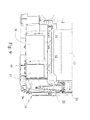
- FIG 3 illustrates a sectional front view of the laundry dryer 10 with the heat pump system according to the preferred embodiment of the present invention.
- the sectional front view relates to the plane A-A in FIG 2 .
- the fluff filter 22 is arranged below the opening 20.
- the fluff filter 22 extends from the bottom of the opening 20 downwards into the basement 24.
- the lower end of the fluff filter 22 is at the about half height of the basement 24.
- the fluff filter 22 comprises a sloped side 22a. Said sloped side 22a allows a better positioning of the fluff filter 22.
- the evaporator filter 26 is arranged in the front portion of the channel 40.
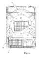
- FIG 4 illustrates the sectional front view of the laundry dryer 10 with the heat pump system and a removed fluff filter 22 according to the preferred embodiment of the present invention.
- the sectional front view relates also to the plane A-A in FIG 2 , wherein the fluff filter 22 has changed its position.
- the fluff filter 22 is removed from the bottom of the opening 20 and detached from the laundry dryer 10.
- a seat 39 for the fluff filter 22 is formed in a bottom of the opening 20, so that the fluff filter 22 can be arranged below said opening 20.
- the fluff filter 22 is removable by pulling upwards out of the bottom of the opening 20. In order to clean the fluff filter 22, the user has just to open the door 30 and to pull said fluff filter 22 along an upward direction.
- FIG 5 illustrates the sectional front view of the laundry dryer 10 with the heat pump system and without the fluff filter 22 according to the preferred embodiment of the present invention.
- the sectional front view relates to the plane A-A in FIG 2 , wherein the fluff filter 22 has been removed.
- the fluff filter 22 is completely removed from the laundry dryer 10, while the evaporator filter 26 is arranged in front of the evaporator 37 and inside the channel 40 in the basement 24.
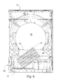
- FIG 6 illustrates the sectional front view of the laundry dryer 10 with the heat pump system and a partially removed evaporator filter 26 according to the preferred embodiment of the present invention.
- the sectional front view relates also to the plane A-A in FIG 2 , wherein the fluff filter 22 fails and the evaporator filter 26 has changed its position.
- FIG 6 clarifies that also the evaporator filter 26 is removable through the bottom of the opening 20 and through the seat 39 for the fluff filter 22, wherein said evaporator filter 26 has to be tilted and then pulled upwards.
- the portion of the air stream circuit, which is provided for the fluff filter 22 and evaporator filter 26, comprises a sloped region 28, so that the evaporator filter 26 can pass through the bottom of the opening 20 and through the seat 39 for the fluff filter 22.
- the sloped region 28 of the air stream circuit corresponds with the sloped side 22a of the fluff filter 22.
- FIG 7 illustrates the sectional front view of the laundry dryer 10 with the heat pump system and the removed evaporator filter 26 according to the preferred embodiment of the present invention.
- the sectional front view relates also to the plane A-A in FIG 2 , wherein the fluff filter 22 fails and the evaporator filter 26 has changed its position.
- FIG 7 also the evaporator filter 26 has been removed from the bottom of the opening 20 and detached from the laundry dryer 10.
- FIG 8 illustrates the sectional front view of the laundry dryer 10 with the heat pump system and without the evaporator filter 26 according to the preferred embodiment of the present invention.
- the sectional front view relates also to the plane A-A in FIG 2 , wherein the fluff filter 22 and the evaporator filter 26 fail.
- FIG 8 clarifies the structure of the portion of the air stream circuit, which is provided for the fluff filter 22 and the evaporator filter 26.
- FIG 9 illustrates a partial lower side view of the opened laundry dryer 10 in which the heat exchangers of the heat pump system according to the preferred embodiment of the present invention have been schematically illustrated.
- the fluff filter 22 is arranged below the bottom of the opening 20.
- the evaporator filter 26 is arranged in front of a seat 32 for the evaporator 37.
- a seat 34 for the condenser 38 is arranged behind the seat 32 for the evaporator 37.
- the evaporator filter 26, the evaporator 37 and the condenser 38 are arranged in the channel 40 extending through the basement 24 from the front side to the rear side.
- FIG 9 clarifies that the evaporator filter 26 is accessible and removable by the user through the bottom of the opening 20, after the fluff filter 22 has been removed.
- FIG 10 illustrates a partial lower side view of an opened laundry dryer 110 according to the prior art, in which the heat exchangers of the heat pump system been schematically illustrated.
- a fluff filter 122 is arranged below the bottom of an opening 120.
- An evaporator filter 126 is arranged in front of a seat 132 for the evaporator 137.
- a seat 134 for the condenser 138 is arranged behind the seat 132 for the evaporator 137.
- the evaporator filter 126, the evaporator 137 and the condenser 38 are arranged in a channel 140 extending through the basement 124 from the front side to the rear side.
- the laundry dryer 110 of the prior art comprises a basement door 136.
- Said basement door 136 has to be opened in order to allow the removal of the evaporator filter 126.
- the inventive laundry dryer 10 allows the access and the removal of the evaporator filter 26 through the bottom of the opening 20, after the fluff filter 22 has been removed.
- the laundry dryer 10 according to the present invention is less complex and costly, due to the absence of the basement door 136. Additionally, the absence of said basement door 136 contributes to an increased leak tightness of the channel 40 and the air stream circuit, since in the prior art laundry dryer 110 the hot air stream can escape from the air stream circuit out of the laundry dryer 10 through the basement door 136.
Abstract
Description
- The present invention relates to a laundry dryer with a heat pump system according to the preamble of claim 1.
- In a laundry dryer with a heat pump system a hot and dry air stream passes a laundry drum containing clothes to be dried. After passing the laundry drum the humidity of the air stream increases and its temperature decreases. Then, the air stream is dehumidified by passing an evaporator of a heat pump circuit. Additionally, the air stream is heated up by a condenser of the heat pump circuit. At last, the air stream is reintroduced again into the laundry drum.
- Further, the air stream carries an amount of fluff removed from the clothes to be dried. Thus, the air stream has to be filtered in order to remove the fluff. One or more filter elements are arranged in the air stream circuit. The filter elements have to be periodically cleaned. However, it is mostly cumbersome for the user to remove the filter elements form the laundry dryer in order to clean said filter elements.
-
US 2009/0100697 A1 discloses a filter apparatus for a domestic appliance. The filter apparatus includes a fluff filter and an evaporator filter connected to each other. The fluff filter and the evaporator filter are connected by a hinge device, so that both filters can be removed and inserted simultaneously. If the fluff filter is removed, then also the evaporator filter is automatically removed from the laundry dryer. However, it is not necessary that the evaporator filter is removed as often as the fluff filter, since the fluff filter has to be cleaned more often than the evaporator filter. The needless removal of the evaporator filter is time consuming and cumbersome. Further, the fluff filter and the evaporator filter are provided as one unit. Thus, said complete unit has to be replaced, if only one of the fluff filter or evaporator filter is damaged. - It is an object of the present invention to provide a laundry dryer with a heat pump system, which allows an easy and timesaving removing and inserting of the fluff filter and evaporator filter.
- The object of the present invention is achieved by the laundry dryer according to claim 1.
- According to the present invention the evaporator filter is accessible, removable and insertable through the bottom of the opening when the fluff filter has been removed, and the fluff filter and the evaporator filter are formed as separated components (elements, bodies, entities), so that they can be removed/inserted one separately from the other. Clearly the access to the evaporator filter (for example for its removal/insertion) is possible only once the fluff filter has been removed, but the fluff filter and the evaporation filter are completely separated entities (i.e. bodies, elements, objects), so that it is possible to remove or insert the fluff filter without having to contemporaneously move the evaporator filter, and, provided that the fluff filter has been removed, it is possible to remove/insert the evaporator filter as an autonomous entity (i.e. body, element, object). In other words the fact that the fluff filter and the evaporator filter can be removed/inserted "one separately from the other" means that they can be handled as independent entities (i.e. bodies, elements, objects), or also that it is not necessary to remove/insert both of them at the same time.
- The core of the present invention is the access to the evaporator filter via that region which is provided for the seat of the fluff filter. A separate door for removing the evaporator filter is not necessary. The complexity of the laundry dryer is reduced. The fluff filter and the evaporator filter can be separately removed for maintenance and/or replacement.
- Advantageously, the fluff filter is removable from the laundry dryer by an upward movement through the bottom of the opening.
- Further, the evaporator filter may be removable from the laundry dryer by at least one tilting movement and an upward movement through the bottom of the opening.
- Preferably, the laundry dryer comprises at least one sloped region between the bottom of the opening and a seat of the evaporator filter, so that the sloped region allows a passing of the tilted evaporator filter.
- Advantageously, the evaporator filter, the evaporator and the condenser are arranged in a horizontal channel in a basement of the laundry dryer. Said channel is a part of the air stream circuit.
- Further, an air stream in the air stream circuit may pass the laundry drum from the rear side to the front side of said laundry drum.
- In contrast, the air stream in the air stream circuit may pass the evaporator filter, the evaporator and the condenser from a front portion to a rear portion of the basement of the laundry dryer.
- Advantageously, the air stream passes the fluff filter in a downward direction.
- Preferably, the air stream passes the evaporator filter in a rearward direction.
- Alternatively, the air stream passes the evaporator filter in a downward direction.
- Further, the air stream may pass the evaporator filter in a downward and rearward direction.
- At last, the evaporator filter may be arranged below and behind the fluff filter.
- The novel and inventive features believed to be the characteristic of the present invention are set forth in the appended claims.
- The invention will be described in further detail with reference to the drawings, in which
- FIG 1
- shows a schematic perspective view of a laundry dryerwith a heat pump system according to a preferred embodiment of the present invention,
- FIG 2
- shows a schematic side view of the opened laundry dryer with the heat pump system according to the preferred embodiment of the present invention,
- FIG 3
- shows a sectional front view of the laundry dryer with the heat pump system according to the preferred embodiment of the present invention,
- FIG 4
- shows the sectional front view of the laundry dryer with the heat pump system and a removed fluff filter according to the preferred embodiment of the present invention,
- FIG 5
- shows the sectional front view of the laundry dryer with the heat pump system and without the fluff filter according to the preferred embodiment of the present invention,
- FIG 6
- shows the sectional front view of the laundry dryer with the heat pump system and a partially removed evaporator filter according to the preferred embodiment of the present invention,
- FIG 7
- shows the sectional front view of the laundry dryer with the heat pump system and the removed evaporator filter according to the preferred embodiment of the present invention,
- FIG 8
- shows the sectional front view of the laundry dryer with the heat pump system and without the evaporator filter according to the preferred embodiment of the present invention,
- FIG 9
- shows a partial lower side view of the opened laundry dryer with removed heat exchangers of the heat pump system according to the preferred embodiment of the present invention, and
- FIG 10
- shows a partial lower side view of the opened laundry dryer with the removed heat exchangers of the pump system according to the prior art.
-
FIG 1 illustrates a schematic perspective view of alaundry dryer 10 with a heat pump system according to a preferred embodiment of the present invention. - A
laundry drum 12 is rotatably arranged inside thecasing 50 of thelaundry dryer 10. An opening 20 is arranged at the front side of thecasing 50 of thelaundry dryer 10 in order to load and unload thelaundry drum 12. Theopening 20 is enclosed by afront panel 14. Abasement front panel 16 is arranged below thefront panel 16 and forms the front side of abasement 24. The lateral portions of thelaundry dryer 10 are covered byside panels 18. Adoor 30 with a window is provided for closing theopening 20. - A
fluff filter 22 is inserted in the bottom of theopening 20. Thefluff filter 22 is provided for removing the fluff from the air steam. Thefluff filter 22 is a part of a closed air stream circuit for the heat pump system. An air stream leaves thelaundry drum 12 through thefluff filter 22 and enters ahorizontal channel 40 provided in thebasement 24 of thelaundry drum 10. The air stream flows in thechannel 40 from the front side to the rear side of thelaundry dryer 10. In thechannel 40 the air stream passes anevaporator filter 26, anevaporator 37 and acondenser 38. Theevaporator filter 26 also removes fluff from the air steam. Theevaporator 37 cools down and dehumidifies the air stream. Thecondenser 38 heats up the air stream. Then, the air stream is reinserted into thelaundry drum 12 again through a rear wall of saidlaundry drum 12. - Preferably, the
fluff filter 22 has the form of a pocket. Further, thefluff filter 22 may be opened and closed in a book-like manner, when saidfluff filter 22 is removed from thelaundry dryer 10. For example, thefluff filter 22 comprises two frames connected to each other by a hinge so that the fluff can be easily removed from saidfluff filter 22. -
FIG 2 illustrates a schematic side view of the openedlaundry dryer 10 with the heat pump system according to the preferred embodiment of the present invention. InFIG 2 theside panel 18 at the left side of thelaundry dryer 10 is removed. - The
laundry drum 12 is arranged in the upper portion of thelaundry dryer 10. Thebasement 24 is arranged below thelaundry drum 12. Thechannel 40 extends in thebasement 24 from the front side to the rear side of thelaundry dryer 10. Thechannel 40 contains theevaporator filter 26, theevaporator 37 and the condenser 38 (not shown inFig 2 ). -
FIG 3 illustrates a sectional front view of thelaundry dryer 10 with the heat pump system according to the preferred embodiment of the present invention. The sectional front view relates to the plane A-A inFIG 2 . - In
FIG 3 thefluff filter 22 is arranged below theopening 20. Thefluff filter 22 extends from the bottom of theopening 20 downwards into thebasement 24. The lower end of thefluff filter 22 is at the about half height of thebasement 24. Thefluff filter 22 comprises a sloped side 22a. Said slopedside 22a allows a better positioning of thefluff filter 22. Further, inFIG 3 theevaporator filter 26 is arranged in the front portion of thechannel 40. -
FIG 4 illustrates the sectional front view of thelaundry dryer 10 with the heat pump system and a removedfluff filter 22 according to the preferred embodiment of the present invention. The sectional front view relates also to the plane A-A inFIG 2 , wherein thefluff filter 22 has changed its position. - In
FIG 4 thefluff filter 22 is removed from the bottom of theopening 20 and detached from thelaundry dryer 10. Aseat 39 for thefluff filter 22 is formed in a bottom of theopening 20, so that thefluff filter 22 can be arranged below saidopening 20. Thefluff filter 22 is removable by pulling upwards out of the bottom of theopening 20. In order to clean thefluff filter 22, the user has just to open thedoor 30 and to pull saidfluff filter 22 along an upward direction. -
FIG 5 illustrates the sectional front view of thelaundry dryer 10 with the heat pump system and without thefluff filter 22 according to the preferred embodiment of the present invention. The sectional front view relates to the plane A-A inFIG 2 , wherein thefluff filter 22 has been removed. InFIG 5 thefluff filter 22 is completely removed from thelaundry dryer 10, while theevaporator filter 26 is arranged in front of theevaporator 37 and inside thechannel 40 in thebasement 24. -
FIG 6 illustrates the sectional front view of thelaundry dryer 10 with the heat pump system and a partially removedevaporator filter 26 according to the preferred embodiment of the present invention. The sectional front view relates also to the plane A-A inFIG 2 , wherein thefluff filter 22 fails and theevaporator filter 26 has changed its position.FIG 6 clarifies that also theevaporator filter 26 is removable through the bottom of theopening 20 and through theseat 39 for thefluff filter 22, wherein saidevaporator filter 26 has to be tilted and then pulled upwards. - The portion of the air stream circuit, which is provided for the
fluff filter 22 andevaporator filter 26, comprises a slopedregion 28, so that theevaporator filter 26 can pass through the bottom of theopening 20 and through theseat 39 for thefluff filter 22. The slopedregion 28 of the air stream circuit corresponds with thesloped side 22a of thefluff filter 22. -
FIG 7 illustrates the sectional front view of thelaundry dryer 10 with the heat pump system and the removedevaporator filter 26 according to the preferred embodiment of the present invention. The sectional front view relates also to the plane A-A inFIG 2 , wherein thefluff filter 22 fails and theevaporator filter 26 has changed its position. In -
FIG 7 also theevaporator filter 26 has been removed from the bottom of theopening 20 and detached from thelaundry dryer 10. -
FIG 8 illustrates the sectional front view of thelaundry dryer 10 with the heat pump system and without theevaporator filter 26 according to the preferred embodiment of the present invention. The sectional front view relates also to the plane A-A inFIG 2 , wherein thefluff filter 22 and theevaporator filter 26 fail.FIG 8 clarifies the structure of the portion of the air stream circuit, which is provided for thefluff filter 22 and theevaporator filter 26. -
FIG 9 illustrates a partial lower side view of the openedlaundry dryer 10 in which the heat exchangers of the heat pump system according to the preferred embodiment of the present invention have been schematically illustrated. - The
fluff filter 22 is arranged below the bottom of theopening 20. Theevaporator filter 26 is arranged in front of aseat 32 for theevaporator 37. Aseat 34 for thecondenser 38 is arranged behind theseat 32 for theevaporator 37. Theevaporator filter 26, theevaporator 37 and thecondenser 38 are arranged in thechannel 40 extending through thebasement 24 from the front side to the rear side. -
FIG 9 clarifies that theevaporator filter 26 is accessible and removable by the user through the bottom of theopening 20, after thefluff filter 22 has been removed. -
FIG 10 illustrates a partial lower side view of an openedlaundry dryer 110 according to the prior art, in which the heat exchangers of the heat pump system been schematically illustrated.
Afluff filter 122 is arranged below the bottom of anopening 120. Anevaporator filter 126 is arranged in front of aseat 132 for theevaporator 137. Aseat 134 for thecondenser 138 is arranged behind theseat 132 for theevaporator 137. Theevaporator filter 126, theevaporator 137 and thecondenser 38 are arranged in achannel 140 extending through thebasement 124 from the front side to the rear side.
Instead of thebasement front panel 24 of theinventive laundry dryer 10, thelaundry dryer 110 of the prior art comprises abasement door 136. Saidbasement door 136 has to be opened in order to allow the removal of theevaporator filter 126. In contrast, theinventive laundry dryer 10 allows the access and the removal of theevaporator filter 26 through the bottom of theopening 20, after thefluff filter 22 has been removed. Thelaundry dryer 10 according to the present invention is less complex and costly, due to the absence of thebasement door 136. Additionally, the absence of saidbasement door 136 contributes to an increased leak tightness of thechannel 40 and the air stream circuit, since in the priorart laundry dryer 110 the hot air stream can escape from the air stream circuit out of thelaundry dryer 10 through thebasement door 136.
Claims (12)
- A laundry dryer (10) with a heat pump system, wherein:- the laundry dryer (10) includes a rotatable laundry drum (12),- an opening (20) is arranged in the front side of the laundry dryer (10),- the opening (20) allows an access to the interior of the laundry drum (12),- the heat pump system includes an air stream circuit comprising a removable fluff filter (22), a removable evaporator filter (26), an evaporator (37) and a condenser (38),- the evaporator (37) and the condenser (38) are arranged in a basement of the laundry dryer (10),- the evaporator filter (26) is arranged upstream the evaporator (37),- the fluff filter (22) is arranged at least partially below a bottom of the opening (20),- the evaporator filter (26) is arranged below and/or behind the fluff filter (22), and- the fluff filter (22) and the evaporator filter (26) are accessible, removable and insertable through the bottom of the opening (20),characterized in that
said fluff filter (22) and said evaporator filter (26) are formed as separated components, so that they can be removed/inserted one separately from the other. - The laundry dryer according to claim 1,
characterized in that
the fluff filter (22) is removable from the laundry dryer (10) by an upward movement through the bottom of the opening (20). - The laundry dryer according to claim 1 or 2, characterized in that
the evaporator filter (26) is removable from the laundry dryer (10) by at least one tilting movement and an upward movement through the bottom of the opening (20). - The laundry dryer according to any one of the preceding claims,
characterized in that
the laundry dryer (10) comprises at least one sloped region (28) between the bottom of the opening (20) and a seat of the evaporator filter (26), so that the sloped region (28) allows a passing of the tilted evaporator filter (26). - The laundry dryer according to any one of the preceding claims,
characterized in that
the evaporator filter (26), the evaporator (37) and the condenser (38) are arranged in a substantially horizontal channel (40) in a basement (24) of the laundry dryer (10). - The laundry dryer according to any one of the preceding claims,
characterized in that
an air stream in the air stream circuit passes the laundry drum (12) from the rear side to the front side of said laundry drum (12). - The laundry dryer according to any one of the preceding claims,
characterized in that
the air stream in the air stream circuit passes the evaporator filter (26), the evaporator (37) and the condenser (38) from a front portion to a rear portion of the basement (24) of the laundry dryer (10). - The laundry dryer according to any one of the preceding claims,
characterized in that
the air stream (16) passes the fluff filter (22) in a downward direction. - The laundry dryer according to any one of the preceding claims,
characterized in that
the air stream (16) passes the evaporator filter (26) in a rearward direction (10). - The laundry dryer according to any one of the claims 1 to 8,
characterized in that
the air stream (16) passes the evaporator filter (26) in a downward direction. - The laundry dryer according to any one of the claims 1 to 8,
characterized in that
the air stream (16) passes the evaporator filter (26) in a downward and rearward direction. - The laundry dryer according to any one of the preceding claims,
characterized in that
the evaporator filter (26) is arranged below and behind the fluff filter (22).
Priority Applications (1)
| Application Number | Priority Date | Filing Date | Title |
|---|---|---|---|
| EP11184856.0A EP2581489A1 (en) | 2011-10-12 | 2011-10-12 | A heat pump laundry dryer with air stream filters |
Applications Claiming Priority (1)
| Application Number | Priority Date | Filing Date | Title |
|---|---|---|---|
| EP11184856.0A EP2581489A1 (en) | 2011-10-12 | 2011-10-12 | A heat pump laundry dryer with air stream filters |
Publications (1)
| Publication Number | Publication Date |
|---|---|
| EP2581489A1 true EP2581489A1 (en) | 2013-04-17 |
Family
ID=44992547
Family Applications (1)
| Application Number | Title | Priority Date | Filing Date |
|---|---|---|---|
| EP11184856.0A Withdrawn EP2581489A1 (en) | 2011-10-12 | 2011-10-12 | A heat pump laundry dryer with air stream filters |
Country Status (1)
| Country | Link |
|---|---|
| EP (1) | EP2581489A1 (en) |
Cited By (12)
| Publication number | Priority date | Publication date | Assignee | Title |
|---|---|---|---|---|
| DE102013110937A1 (en) * | 2013-10-02 | 2015-04-02 | Miele & Cie. Kg | clothes dryer |
| EP2857573A1 (en) * | 2013-10-02 | 2015-04-08 | Miele & Cie. KG | Bag for filtering of lint |
| US10087569B2 (en) | 2016-08-10 | 2018-10-02 | Whirlpool Corporation | Maintenance free dryer having multiple self-cleaning lint filters |
| US10161665B2 (en) | 2013-03-14 | 2018-12-25 | Whirlpool Corporation | Refrigerator cooling system having secondary cooling loop |
| CN109691942A (en) * | 2017-10-23 | 2019-04-30 | 青岛海尔洗碗机有限公司 | A kind of heat-pump-type dish-washing machine and its control method |
| US10502478B2 (en) | 2016-12-20 | 2019-12-10 | Whirlpool Corporation | Heat rejection system for a condenser of a refrigerant loop within an appliance |
| US10514194B2 (en) | 2017-06-01 | 2019-12-24 | Whirlpool Corporation | Multi-evaporator appliance having a multi-directional valve for delivering refrigerant to the evaporators |
| US10519591B2 (en) | 2016-10-14 | 2019-12-31 | Whirlpool Corporation | Combination washing/drying laundry appliance having a heat pump system with reversible condensing and evaporating heat exchangers |
| US10544539B2 (en) | 2017-02-27 | 2020-01-28 | Whirlpool Corporation | Heat exchanger filter for self lint cleaning system in dryer appliance |
| US10718082B2 (en) | 2017-08-11 | 2020-07-21 | Whirlpool Corporation | Acoustic heat exchanger treatment for a laundry appliance having a heat pump system |
| US10738411B2 (en) | 2016-10-14 | 2020-08-11 | Whirlpool Corporation | Filterless air-handling system for a heat pump laundry appliance |
| US11015281B2 (en) | 2017-09-26 | 2021-05-25 | Whirlpool Corporation | Laundry appliance having a maintenance free lint removal system |
Citations (4)
| Publication number | Priority date | Publication date | Assignee | Title |
|---|---|---|---|---|
| DE4304372A1 (en) * | 1993-02-13 | 1994-08-18 | Miele & Cie | Drying appliance, especially condensation-type laundry dryer, with a heat pump |
| DE102007012071A1 (en) * | 2007-03-13 | 2008-09-18 | BSH Bosch und Siemens Hausgeräte GmbH | Washer dryer with improved lint removal and process for its operation |
| US7458171B1 (en) * | 2007-01-29 | 2008-12-02 | Lentz Luke E | Dehumidifier clothes dryer apparatus |
| EP2050862A1 (en) * | 2007-10-18 | 2009-04-22 | BSH Bosch und Siemens Hausgeräte GmbH | Fibre material filtering device and household device with such a fibre material filtering device |
-
2011
- 2011-10-12 EP EP11184856.0A patent/EP2581489A1/en not_active Withdrawn
Patent Citations (5)
| Publication number | Priority date | Publication date | Assignee | Title |
|---|---|---|---|---|
| DE4304372A1 (en) * | 1993-02-13 | 1994-08-18 | Miele & Cie | Drying appliance, especially condensation-type laundry dryer, with a heat pump |
| US7458171B1 (en) * | 2007-01-29 | 2008-12-02 | Lentz Luke E | Dehumidifier clothes dryer apparatus |
| DE102007012071A1 (en) * | 2007-03-13 | 2008-09-18 | BSH Bosch und Siemens Hausgeräte GmbH | Washer dryer with improved lint removal and process for its operation |
| EP2050862A1 (en) * | 2007-10-18 | 2009-04-22 | BSH Bosch und Siemens Hausgeräte GmbH | Fibre material filtering device and household device with such a fibre material filtering device |
| US20090100697A1 (en) | 2007-10-18 | 2009-04-23 | Bsh Bosch Und Siemens Hausgeraete Gmbh | Fluff filter apparatus and domestic appliance containing such a fluff filter apparatus |
Cited By (23)
| Publication number | Priority date | Publication date | Assignee | Title |
|---|---|---|---|---|
| US10161665B2 (en) | 2013-03-14 | 2018-12-25 | Whirlpool Corporation | Refrigerator cooling system having secondary cooling loop |
| EP2857573A1 (en) * | 2013-10-02 | 2015-04-08 | Miele & Cie. KG | Bag for filtering of lint |
| EP2878729A1 (en) | 2013-10-02 | 2015-06-03 | Miele & Cie. KG | Tumble dryer |
| DE102013110937B4 (en) * | 2013-10-02 | 2016-11-17 | Miele & Cie. Kg | clothes dryer |
| DE102013110937A1 (en) * | 2013-10-02 | 2015-04-02 | Miele & Cie. Kg | clothes dryer |
| US10087569B2 (en) | 2016-08-10 | 2018-10-02 | Whirlpool Corporation | Maintenance free dryer having multiple self-cleaning lint filters |
| US10633785B2 (en) | 2016-08-10 | 2020-04-28 | Whirlpool Corporation | Maintenance free dryer having multiple self-cleaning lint filters |
| US10738411B2 (en) | 2016-10-14 | 2020-08-11 | Whirlpool Corporation | Filterless air-handling system for a heat pump laundry appliance |
| US11542653B2 (en) | 2016-10-14 | 2023-01-03 | Whirlpool Corporation | Filterless air-handling system for a heat pump laundry appliance |
| US11299834B2 (en) | 2016-10-14 | 2022-04-12 | Whirlpool Corporation | Combination washing/drying laundry appliance having a heat pump system with reversible condensing and evaporating heat exchangers |
| US10519591B2 (en) | 2016-10-14 | 2019-12-31 | Whirlpool Corporation | Combination washing/drying laundry appliance having a heat pump system with reversible condensing and evaporating heat exchangers |
| US10502478B2 (en) | 2016-12-20 | 2019-12-10 | Whirlpool Corporation | Heat rejection system for a condenser of a refrigerant loop within an appliance |
| US10544539B2 (en) | 2017-02-27 | 2020-01-28 | Whirlpool Corporation | Heat exchanger filter for self lint cleaning system in dryer appliance |
| US11142864B2 (en) | 2017-02-27 | 2021-10-12 | Whirlpool Corporation | Heat exchanger filter for self lint cleaning system in dryer appliance |
| US11634856B2 (en) | 2017-02-27 | 2023-04-25 | Whirlpool Corporation | Heat exchanger filter for self lint cleaning system in dryer appliance |
| US11920288B2 (en) | 2017-02-27 | 2024-03-05 | Whirlpool Corporation | Heat exchanger filter for self lint cleaning system in dryer appliance |
| US10823479B2 (en) | 2017-06-01 | 2020-11-03 | Whirlpool Corporation | Multi-evaporator appliance having a multi-directional valve for delivering refrigerant to the evaporators |
| US10514194B2 (en) | 2017-06-01 | 2019-12-24 | Whirlpool Corporation | Multi-evaporator appliance having a multi-directional valve for delivering refrigerant to the evaporators |
| US10718082B2 (en) | 2017-08-11 | 2020-07-21 | Whirlpool Corporation | Acoustic heat exchanger treatment for a laundry appliance having a heat pump system |
| US11015281B2 (en) | 2017-09-26 | 2021-05-25 | Whirlpool Corporation | Laundry appliance having a maintenance free lint removal system |
| US11739472B2 (en) | 2017-09-26 | 2023-08-29 | Whirlpool Corporation | Laundry appliance having a maintenance free lint removal system |
| CN109691942B (en) * | 2017-10-23 | 2023-01-03 | 青岛海尔洗碗机有限公司 | Heat pump type dish washing machine and control method thereof |
| CN109691942A (en) * | 2017-10-23 | 2019-04-30 | 青岛海尔洗碗机有限公司 | A kind of heat-pump-type dish-washing machine and its control method |
Similar Documents
| Publication | Publication Date | Title |
|---|---|---|
| EP2581489A1 (en) | A heat pump laundry dryer with air stream filters | |
| CN103608511B (en) | Roller type clothes drying machine | |
| CN101775735B (en) | Dryer and foreign material removing apparatus | |
| CN101748584B (en) | Dryer and apparatus for removing lint thereof | |
| EP2870284B1 (en) | Laundry dryer | |
| EP2458071A1 (en) | Filter for filtering impurities in a dryer, and dryer thereof | |
| KR20170009656A (en) | Fabric dryer | |
| AU2018274956B2 (en) | Laundry Dryer Apparatus | |
| KR102366458B1 (en) | Fabric dryer | |
| WO2015028237A1 (en) | A drying air filter for a laundry dryer and a laundry dryer | |
| CN102099523A (en) | Laundry treating apparatus | |
| EP3562988B1 (en) | A laundry dryer comprising a filter assembly and a method to clean a filter assembly | |
| EP2570547B1 (en) | Fluff filter for a laundry drying machine | |
| CN110114531B (en) | Laundry dryer comprising a filter assembly and method of cleaning a filter assembly | |
| EP2581488B1 (en) | A laundry dryer with a heat pump system and filter | |
| EP3008237B1 (en) | Laundry treatment apparatus having a condensate tank and method of condensate collecting and draining | |
| CN101506589A (en) | Dehumidifier | |
| EP2460929A1 (en) | Washer dryer with heat pump | |
| EP2562304B1 (en) | Air stream filter for a laundry dryer | |
| EP3000929B1 (en) | Lint strainer for laundry care apparatus | |
| EP2314758B1 (en) | A laundry dryer machine having a filter for condensed water | |
| RU2664371C1 (en) | Laundry drying machine with air drying filter | |
| EP3112526B1 (en) | Support device for air filters for drying or washing/drying machines, air filter for drying machines or washing/drying machines provided with said support device and drying or washing/drying machine provided with said filter | |
| CN110114529A (en) | The method of clothesdrier and cleaning filter assemblies including filter assemblies | |
| KR102577345B1 (en) | Laundry drying apparatus |
Legal Events
| Date | Code | Title | Description |
|---|---|---|---|
| PUAI | Public reference made under article 153(3) epc to a published international application that has entered the european phase |
Free format text: ORIGINAL CODE: 0009012 |
|
| AK | Designated contracting states |
Kind code of ref document: A1 Designated state(s): AL AT BE BG CH CY CZ DE DK EE ES FI FR GB GR HR HU IE IS IT LI LT LU LV MC MK MT NL NO PL PT RO RS SE SI SK SM TR |
|
| AX | Request for extension of the european patent |
Extension state: BA ME |
|
| 17P | Request for examination filed |
Effective date: 20131017 |
|
| RBV | Designated contracting states (corrected) |
Designated state(s): AL AT BE BG CH CY CZ DE DK EE ES FI FR GB GR HR HU IE IS IT LI LT LU LV MC MK MT NL NO PL PT RO RS SE SI SK SM TR |
|
| STAA | Information on the status of an ep patent application or granted ep patent |
Free format text: STATUS: THE APPLICATION IS DEEMED TO BE WITHDRAWN |
|
| 18D | Application deemed to be withdrawn |
Effective date: 20180501 |