EP2579002A1 - Magnetic encoder - Google Patents
Magnetic encoder Download PDFInfo
- Publication number
- EP2579002A1 EP2579002A1 EP11789675.3A EP11789675A EP2579002A1 EP 2579002 A1 EP2579002 A1 EP 2579002A1 EP 11789675 A EP11789675 A EP 11789675A EP 2579002 A1 EP2579002 A1 EP 2579002A1
- Authority
- EP
- European Patent Office
- Prior art keywords
- magnetic
- magnetic encoder
- track
- tracks
- encoder
- Prior art date
- Legal status (The legal status is an assumption and is not a legal conclusion. Google has not performed a legal analysis and makes no representation as to the accuracy of the status listed.)
- Granted
Links
Images


Classifications
-
- G—PHYSICS
- G01—MEASURING; TESTING
- G01D—MEASURING NOT SPECIALLY ADAPTED FOR A SPECIFIC VARIABLE; ARRANGEMENTS FOR MEASURING TWO OR MORE VARIABLES NOT COVERED IN A SINGLE OTHER SUBCLASS; TARIFF METERING APPARATUS; MEASURING OR TESTING NOT OTHERWISE PROVIDED FOR
- G01D5/00—Mechanical means for transferring the output of a sensing member; Means for converting the output of a sensing member to another variable where the form or nature of the sensing member does not constrain the means for converting; Transducers not specially adapted for a specific variable
- G01D5/12—Mechanical means for transferring the output of a sensing member; Means for converting the output of a sensing member to another variable where the form or nature of the sensing member does not constrain the means for converting; Transducers not specially adapted for a specific variable using electric or magnetic means
- G01D5/244—Mechanical means for transferring the output of a sensing member; Means for converting the output of a sensing member to another variable where the form or nature of the sensing member does not constrain the means for converting; Transducers not specially adapted for a specific variable using electric or magnetic means influencing characteristics of pulses or pulse trains; generating pulses or pulse trains
- G01D5/24428—Error prevention
- G01D5/24433—Error prevention by mechanical means
- G01D5/24438—Special design of the sensing element or scale
-
- G—PHYSICS
- G01—MEASURING; TESTING
- G01D—MEASURING NOT SPECIALLY ADAPTED FOR A SPECIFIC VARIABLE; ARRANGEMENTS FOR MEASURING TWO OR MORE VARIABLES NOT COVERED IN A SINGLE OTHER SUBCLASS; TARIFF METERING APPARATUS; MEASURING OR TESTING NOT OTHERWISE PROVIDED FOR
- G01D5/00—Mechanical means for transferring the output of a sensing member; Means for converting the output of a sensing member to another variable where the form or nature of the sensing member does not constrain the means for converting; Transducers not specially adapted for a specific variable
- G01D5/12—Mechanical means for transferring the output of a sensing member; Means for converting the output of a sensing member to another variable where the form or nature of the sensing member does not constrain the means for converting; Transducers not specially adapted for a specific variable using electric or magnetic means
- G01D5/244—Mechanical means for transferring the output of a sensing member; Means for converting the output of a sensing member to another variable where the form or nature of the sensing member does not constrain the means for converting; Transducers not specially adapted for a specific variable using electric or magnetic means influencing characteristics of pulses or pulse trains; generating pulses or pulse trains
- G01D5/245—Mechanical means for transferring the output of a sensing member; Means for converting the output of a sensing member to another variable where the form or nature of the sensing member does not constrain the means for converting; Transducers not specially adapted for a specific variable using electric or magnetic means influencing characteristics of pulses or pulse trains; generating pulses or pulse trains using a variable number of pulses in a train
- G01D5/2451—Incremental encoders
-
- G—PHYSICS
- G01—MEASURING; TESTING
- G01D—MEASURING NOT SPECIALLY ADAPTED FOR A SPECIFIC VARIABLE; ARRANGEMENTS FOR MEASURING TWO OR MORE VARIABLES NOT COVERED IN A SINGLE OTHER SUBCLASS; TARIFF METERING APPARATUS; MEASURING OR TESTING NOT OTHERWISE PROVIDED FOR
- G01D2205/00—Indexing scheme relating to details of means for transferring or converting the output of a sensing member
- G01D2205/80—Manufacturing details of magnetic targets for magnetic encoders
Definitions
- the present invention relates to a magnetic encoder which may be used to detect rotation, rotational angles, and linear movements of various devices.
- a technique that belongs to the field of bearing elements which makes use of magnetic sensors arranged in the form of a line to obtain interpolated pulse signals (see the Patent Documents 1 and 2 listed below).
- a technique is disclosed which makes use of a magnetic drum having different numbers of magnetic pole pairs per complete rotation and of a plurality of magnetic sensors to calculate absolute angles (see the Patent Document 3 listed below).
- a rotational angles detection device is disclosed which makes use of magnetic sensors such as disclosed in the Patent Documents 1 and 2 to obtain phase difference between two different magnetic encoders and which uses the phase difference to calculate absolute angles (see the Patent Document 4 listed below).
- a technique is disclosed which makes use of a magnetic encoder such as employed in the Patent Document 4 and which interposes a gap between plural rows of adjacent magnetic tracks (see the Patent Document 5 listed below).
- a technique which makes use of a magnetic encoder such as employed in the Patent Document 4 and which interposes a magnetic material between plural rows of adjacent magnetic tracks (see the Patent Document 6 listed below).
- a technique which manufactures a magnetic encoder that includes a plurality of magnetic poles formed thereto (see the Patent Document 7 listed below).
- a technique is disclosed which relates to, with respect to a magnetic encoder such as disclosed in the Patent Documents 1 and 2, plural rows of tracks that are out of phase from each other (see the Patent Document 8 listed below).
- a plural-row magnetic encoder is often used to provide a rotation sensor or an angle sensor for control of a rotational device.
- reduction of the space between the plural magnetic tracks may lead to increase in magnetic interference between the magnetic tracks, thereby resulting in reduced detection sensitivity.
- Such undesirable effects of magnetic interference may be greater when the plural rows of magnetic tracks are brought closer as well as when magnetic sensors are positioned at locations closer to a boundary line defined between the plural rows of magnetic tracks.
- a sufficient air gap may be required between a magnetic encoder - which is a rotational member - and sensors - which are stationary members, to safely prevent possible failures that may be caused by, for example, an accidental contact.
- a separator made of a magnetic material may be interposed between the plural rows of magnetic tracks to reduce such magnetic interference.
- this may complicate the construction of a magnetic encoder, leading to increase in the production cost.
- a magnetic material may short-circuit part of magnetic field emanating from a magnetic encoder, thereby leading to reduced magnetic force at sensors. Increased distance between the magnetic tracks may reduce magnetic interference, but this may require a larger mounting space, preventing reduction in the size of a detection device.
- a minimum arrangement space for sensors may be preferred in order to reduce the size of a device.
- a magnetic encoder may be required which includes plural rows of tracks formed within a narrow width of 2 mm to 10 mm, approximately.
- the incorporation of such a magnetic encoder may need to be such that an air gap in the range of 0.3 mm to 4 mm, approximately, will be ensured between the surface of the magnetic encoder and the sensors.
- Various factors such as mechanical tolerances and operating environments often make it difficult to realize a narrower gap between the surface of the magnetic encoder and the sensors.
- the sensors be arranged at positions that correspond to a proximity to the centers of the respective tracks, since, as far as the magnetic field strength detected by the sensors is concerned, the strongest magnetic force emanates from the centers of the widths of the respective tracks as measured along the direction of rotation of the respective tracks.
- a demand has exited for a plural-row magnetic encoder which, despite the aforementioned constraints, allows sensors to be positioned where sufficient magnetic field strength is ensured so that they can accurately read precision magnetic signals.
- magnetic patterns formed on the plural rows of magnetic tracks had to be such that they define a possibly clearest boundary between them to prevent them from influencing each other, so that precision magnetic signals are ensured at the sensors' detecting positions.
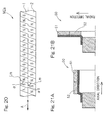
- Fig. 21A shows a longitudinal cross sectional view of a conventional radial-type magnetic encoder 50
- Fig. 21B shows a longitudinal cross sectional view of a conventional axial-type magnetic encoder 50
- Fig. 22A shows the magnetization of the surfaces of the magnetic tracks of the magnetic encoder 50, to which desired magnetic patterns have been magnetized.
- Fig. 22B shows the magnetic patterns detected by sensors that are arranged spaced through an air gap of 1 mm from the magnetic encoder 50 of Fig. 22A .
- the magnetization in a proximity to the boundary between the tracks 51, 52 shows a gradual transition on detected magnetic patterns.
- information provided by magnetic sensors that read signals of the respective tracks 51, 52 will be of lower accuracy.
- Fig. 23A shows a longitudinal cross sectional view of a conventional radial-type magnetic encoder 53
- Fig. 23B shows a longitudinal cross sectional view of a conventional axial-type magnetic encoder 53
- Figs. 24A and 24B illustrate a plural-row magnetic encoder 53 such as disclosed in the Patent Document 4, while Fig. 25 illustrates a general concept of errors.
- the illustrated magnetic encoder is an ideally magnetized, namely, error-free magnetic encoder which includes Ch1 and Ch2 tracks having eight and seven pairs of magnetic poles, respectively.
- the air gap is 1 mm.
- Figs. 24A and 24B illustrate the magnetic patterns on the Ch1 track and Ch2 track, respectively, and each of them is assumed to contain no errors because of ideal magnetization.
- the Ch1 track is affected by the interference of magnetism from the magnetic pattern on the Ch2 track.
- the magnetic pattern on the Ch2 track has magnetic pole pairs, each being larger than each of the magnetic pole pairs of the magnetic pattern on the Ch1 track.
- each of the magnetic pole pairs (or magnetic pole pairs operating on the actual position of the corresponding sensor) on the Ch1 track has a longer apparent length, thus producing an error of positive polarity.
- each of the error patterns per complete rotation is sinusoidal.
- the error pattern on the Ch2 track has a property that is inverse to that of the error pattern on the Ch1 track.
- An object of the present invention is to provide a magnetic encoder of reduced size and simplified construction that includes plural rows of magnetic encoder tracks, which enables accurate detection, by sensor(s), of signals of equal pitch for detection of rotation under the interference of magnetism between the tracks, while at the same time ensuring a desired air gap.
- a magnetic encoder is a magnetic encoder which includes plural rows of magnetic encoder tracks that are arranged adjacent to each other and are formed integrally with the magnetic encoder, at least one magnetic encoder track of the magnetic encoder tracks including a magnetic pattern having N poles and S poles arranged in alternate fashion magnetized thereto to generate signals of equal pitch for detection of rotation, the magnetic pattern, the magnetic encoder being configured to be employed spaced through an air gap from sensors that read magnetic signals of the respective magnetic encoder tracks, the at least one magnetic encoder track being configured such that the magnetic pattern thereof acting on position of the corresponding sensor is, under an interference of magnetism of the plural rows of magnetic encoder tracks, detected by the corresponding sensor as an equal pitch magnetic pattern.
- the magnetic patterns actually detected by sensors at positions corresponding to the desired air gap will be offset from ideal magnetic patterns. This is caused by plural rows of magnetic encoder tracks being brought close to be integral with each other such that magnetism of the magnetic patterns magnetized to the respective rows interferes with each other.
- the at least one magnetic encoder track is configured such that the magnetic pattern thereof acting on position of the corresponding sensor is, under the interference of magnetism of plural rows of magnetic encoder tracks, detected by the corresponding sensor as an equal pitch magnetic pattern.
- the interference of magnetism of plural rows of magnetic encoder tracks can be used to achieve detection of an equal pitch magnetic pattern by corresponding sensor(s) at its/their actual detecting position(s), while also ensuring a desired air gap and without the need to complicate the construction of a magnetic encoder.
- corresponding sensor(s) can accurately detect signals of equal pitch for detection of rotation.
- This configuration eliminates the need to provide or makes it optional to provide a space between plural rows of magnetic encoder tracks or to provide interposition of, for example, a magnetic material between the tracks. In this way, the construction of a magnetic encoder can be simplified, thereby leading to reduction in the production cost of the magnetic encoder and/or reduction in the size of the magnetic encoder.
- the plural rows of magnetic encoder tracks may include the plural rows of magnetic encoder tracks include a magnetic encoder track that is different from the one magnetic encoder track and is adjacent to the one magnetic encoder track, the different magnetic encoder track including a magnetic pattern magnetized thereto to provide a reference position for rotation, the magnetic pattern magnetized to the different magnetic encoder track having the same number of magnetic poles as the one magnetic encoder track, and a phase offset with respect to the magnetic pattern magnetized to the one magnetic encoder track, and the different magnetic encoder track being configured to provide, by the use of the phase offset with respect to the magnetic pattern magnetized to the one magnetic encoder track, the reference position for rotation.
- the plural rows of magnetic encoder tracks may include a magnetic encoder track that is different from the one magnetic encoder track and is adjacent to the one magnetic encoder track, the different magnetic encoder track including a magnetic pattern magnetized thereto to provide a reference position for rotation, the magnetic pattern magnetized to the different magnetic encoder track including that has an N or S magnetic pole at a certain circumferential location with the remaining circumferential portion being not magnetized.
- the plural rows of magnetic encoder tracks may include a magnetic encoder track that is different from the one magnetic encoder track and is adjacent to the one magnetic encoder track, the different magnetic encoder track including a magnetic pattern magnetized thereto to provide a reference position for rotation, the magnetic pattern magnetized to the different magnetic encoder track including an N or S magnetic pole at a certain circumferential location as well as a magnetic pole, which is an opposite magnetic pole to the magnetic pole on the certain circumferential location, at a different circumferential location.
- Each of the magnetic encoder tracks may be formed to have a track width as measured along arrangement direction of the magnetic encoder tracks, with the track width being in the range of 1 mm to 5 mm.
- arrangement direction refers to a direction that is parallel to a rotation axis of a magnetic encoder or a direction that is perpendicular to a rotation axis of a magnetic encoder.
- the selection of the air gap affects the magnetic field strength detected by the sensors.
- the magnetic encoder tracks have respective track widths as measured along the arrangement direction that are in the range of 1 mm to 5 mm, thereby enabling proper detection of magnetic signals of the respective magnetic encoder tracks.
- the plural rows of magnetic encoder tracks may be adjacent through a boundary line, with the magnetic encoder being configured to be employed spaced from the sensors through an air gap that is more than 0.3 mm and is less than 4 mm and with the sensors having respective detector portions positioned over the respective magnetic encoder tracks at locations spaced from the boundary line towards the respective magnetic encoder tracks by respective distances in the range of 0.5 mm to 3 mm.
- the sensors have respective detector portions positioned over the respective magnetic encoder tracks at locations spaced from the boundary line towards the respective magnetic encoder tracks by respective distances in the range of 0.5 mm to 3 mm
- sensor(s) may accidentally contact with magnetic encoder track(s) which contain(s), for example, rubber or resin, thus damaging the surface of the magnetic encoder track(s).
- a foreign material may be easily trapped between magnetic encoder track(s) and sensor(s), thus damaging the surface of the magnetic encoder track(s).
- the air gap is equal to or more than 4 mm, reduced magnetization strength is inevitable and proper control of the interference of magnetism between plural rows of magnetic encoder tracks will be difficult. This makes it hard for sensor(s) to generate precise magnetic field signals at its/their detecting position(s).
- the magnetic encoder tracks may include magnetic encoder track(s) including a rare earth sintered magnet, a magnet containing a rare earth magnet powder mixed in a rubber or resin, the magnetic encoder track includes a ferrite sintered magnet or a magnet containing a ferrite power mixed in a rubber or a resin, the magnetic encoder track having a thickness that is more than 0.5 mm and is less than 4 mm.
- the magnetic encoder tracks have thickness equal to or less than 0.5 mm, considerable demagnetizing field will be formed inside the respective magnetic encoder tracks. This leads to higher chance of causing irreversible flux loss at high temperatures, thereby resulting in reduced reliability as a magnet.
- the magnetic encoder track has thickness equal to or more than 4 mm, this makes it difficult to pass a sufficient amount of flux for magnetization through the magnetic encoder track(s) since the distance between magnetization heads increases.
- the respective thickness of the magnetic encoder track is more than 0.5 mm. This leads to formation of smaller demagnetizing field inside the respective magnetic encoder tracks. This also leads to lower chance of causing irreversible flux loss at high temperatures, thereby resulting in improved reliability as a magnet.
- the magnetic pattern magnetized to the one magnetic encoder track may include magnetic poles, each having a length L as measured along a circumferential direction of the magnetic encoder track, the length L being in the range of 0.3 mm to 5 mm, and wherein each of the magnetic encoder tracks is so formed that the length L has a relationship with a track width W, as measured along arrangement direction of the magnetic encoder tracks, of W>L.
- the relationship of W>L can minimize the unwanted effects of possible errors brought by the interference of magnetism between the plural rows of magnetic encoder tracks.
- the length L of each magnetic pole being in the range of 0.3 mm to 5 mm enables necessary and sufficient detection of magnetic signals of the respective magnetic encoder tracks.
- the plural rows of the adjacent magnetic encoder tracks may include respective magnetic patterns magnetized thereto having different numbers of magnetic poles, with the magnetic pattern magnetized to the at least one magnetic encoder track being such an unequal pitch magnetic pattern that the magnetic pattern thereof acting on position of the corresponding sensor is, under the interference of magnetism of plural rows of magnetic encoder tracks, detected by the corresponding sensor as an equal pitch magnetic pattern.
- the magnetic patterns thereof acting on positions of the corresponding sensors are actually detected by the corresponding sensors as containing error patterns that include errors brought by the interference of magnetism of the respective tracks having different numbers of magnetic pole pairs.
- the magnetic pattern magnetized to the at least one magnetic encoder track is such an unequal pitch magnetic pattern that the magnetic pattern thereof acting on position of the corresponding sensor is, under the interference of magnetism of plural rows of magnetic encoder tracks, detected by the corresponding sensor as an equal pitch magnetic pattern.
- the plural rows of magnetic encoder tracks are brought close to be integral with each other, causing interference of magnetism between the respective magnetic encoder tracks such that the interference generally cancels each other's error patterns and reduces errors.
- the magnetic pattern that operates on position of the sensor may be detected by the corresponding sensor at its actual detecting position as magnetic pattern that are closer to ideal, error-free magnetic pattern. This enables, despite the presence of plural rows of magnetic encoder tracks, accurate detection, by the sensor, of signals of equal pitch for detection of rotation.
- Magnetic material(s) may be further provided so as to be interposed between the plural rows of the adjacent magnetic encoder tracks.
- a core having the plural rows of magnetic encoder tracks disposed thereon may be further provided, with the plural rows of the adjacent magnetic encoder tracks having gap interposed therebetween. Any one of these configurations can further enhance the effect or advantage of the interference of magnetism between the respective magnetic encoder tracks that generally cancels each other's error patterns.
- the plural rows of magnetic encoder tracks may include a magnetic encoder track that is different from the one magnetic encoder track and is adjacent to the one magnetic encoder track, the one magnetic encoder track has a track width as measured along arrangement direction of the magnetic encoder tracks, and the different, adjacent magnetic encoder track has a track width, as measured along arrangement direction of the magnetic encoder tracks, different from the track width of the one magnetic encoder track.
- This provides freedom in arrangement of sensors, thereby facilitating the incorporation of a magnetic encoder into a device.
- the plural rows of the adjacent magnetic encoder tracks may include respective detected surfaces extending on different planes.
- a magnetic encoder is a magnetic encoder which includes plural rows of linear magnetic encoder tracks that are arranged adjacent to each other and are formed integrally with the magnetic encoder, with at least one magnetic encoder track of the magnetic encoder tracks including a magnetic pattern magnetized thereto to generate signals of equal pitch for detection of speed and with the magnetized magnetic pattern including N poles and S poles arranged in alternate fashion.
- the magnetic encoder is configured to be employed spaced through an air gap from sensors that read magnetic signals of the respective magnetic encoder tracks.
- the at least one magnetic encoder track is configured such that the magnetic pattern thereof acting on position of the corresponding sensor is, under the interference of magnetism of plural rows of magnetic encoder tracks, detected by the corresponding sensor as an equal pitch magnetic pattern.
- a plural-row magnetic encoder according to present invention may be applied to a linear motion encoder.
- at least one magnetic encoder track is configured such that the magnetic pattern thereof acting on position of the corresponding sensor is, under the interference of magnetism of plural rows of magnetic encoder tracks, detected by the corresponding sensor as an equal pitch magnetic pattern.
- the interference of magnetism of plural rows of magnetic encoder tracks can be used to achieve detection of an equal pitch magnetic pattern by corresponding sensor(s) at its/their actual detecting position(s), while also ensuring a desired air gap and without the need to complicate the construction of a magnetic encoder.
- corresponding sensor(s) can accurately detect signals of equal pitch.
- the configuration under discussion eliminates the need to provide or makes it optional to provide a space between plural rows of magnetic encoder tracks or to provide interposition of, for example, a magnetic material between the tracks. In this way, the construction of a magnetic encoder can be simplified, thereby leading to reduction in the production cost of the magnetic encoder and/or reduction in the size of the magnetic encoder.
- the present invention encompasses any combination of at least two features disclosed in the claims and/or the specification and/or the drawings. In particular, the present invention encompasses any combination of at least two features in the claims.
- a magnetic encoder according to this embodiment may be used, for example, to detect rotation, rotational angles, and linear movements of various devices.
- a magnetic encoder ME includes plural rows of annular magnetic encoder tracks 1, 2 that are arranged adjacent to each other and are formed integrally with the magnetic encoder ME.
- the magnetic encoder tracks 1, 2 are disposed on a disc-shaped ( Fig. 1B ) or cylindrical ( Fig. 1A ) core 3 such that the magnetic encoder tracks 1, 2 are arranged coaxially and adjacent to each other on a surface of the core 3.
- Fig. 1B disc-shaped
- Fig. 1A cylindrical
- a magnetic encoder ME that includes, for example, a magnetized, axial-type, annular magnetic body may be attached to an outer peripheral surface Da of, for example, a rotational raceway member of a bearing, with a cylindrical segment of the core 3 being force-fitted to the outer peripheral surface Da.
- the magnetic encoder tracks 1, 2 include, for example, a rubber, plastic, or a sintered element containing a magnetic power therein, that are magnetized as a rubber magnet, a plastic magnet or a sintered magnet, respectively.
- the annular magnetic body is not limited to an axial-type, annular magnetic body; for example, the annular magnetic body may be a radial-type, annular magnetic body such as shown in Fig. 1A .
- the magnetic encoder tracks 1, 2 include a magnet containing ferrite that is sinter-molded (i.e. so-called a ferrite sintered magnet), or a molded magnet containing a ferrite magnetic power mixed in a rubber or resin.
- the material for the magnet may include a rare earth magnet, but ferrite is more advantageous under regular operating conditions, since ferrite is inexpensive and can be easily magnetized.
- each of the magnetic encoder tracks 1, 2 includes N poles and S poles magnetized thereto in alternate fashion along a circumferential direction of the each magnetic encoder track 1, 2. As shown in Fig. 1A and Fig.
- the magnetic encoder ME is employed and arranged such that the respective detected surfaces thereof are spaced apart through an air gap Gp from sensors Sa, Sb that read magnetic signals of the respective magnetic encoder tracks 1, 2, with the air gap Gp being more than 0.3 mm and less than 4 mm.
- the plural rows of magnetic encoder tracks 1, 2 are adjacent through a boundary line Lk.
- the sensors Sa, Sb have respective detector portions that are positioned over the respective magnetic encoder tracks 1, 2 at locations spaced from the boundary line Lk towards the respective magnetic encoder tracks 1, 2 by respective distances in the range of 0.5 mm to 3 mm.
- the detector portions of the sensors Sa, Sb are positioned at respective sensor reading positions P1, P2 as depicted by broken lines in diagrams (A) and (B) of Fig. 2 .
- Each of the magnetic encoder tracks 1, 2 has a track width W in the range of 1 mm to 5 mm and includes magnetic poles, each having a length L in the range of 0.3 mm to 5 mm.
- the track width W refers to a track width as measured along arrangement direction of the tracks that is perpendicular to the direction of rotation of the magnetic encoder ME.
- the magnetic pole length L refers to the length of each of the magnetic poles of a magnetic pattern, as measured along the direction of rotation of the magnetic encoder ME.
- the track width W and the magnetic pole length L satisfy the relationship of W>L.
- the magnetic encoder tracks 1, 2 have respective thicknesses t1 such as shown in Fig. 1A and Fig. 1B , with the respective thicknesses t1 being more than 0.5 mm and less than 4 mm.
- FIG. 22A shows magnetic patterns magnetized on surface of a magnetic encoder.
- Diagram (B) of Fig. 2 shows magnetic patterns actually detected by sensors Sa, Sb at locations where the detector portions thereof are positioned.
- the magnetic encoder ME includes plural rows (two rows in the illustrated example) of annular magnetic encoder tracks 1, 2 that are arranged adjacent to each other and are formed integrally with the magnetic encoder.
- the magnetic encoder tracks 1, 2 include respective magnetic patterns Pa, Pb magnetized thereto, each including N poles and S poles arranged in alternate fashion.
- One of the magnetic encoder tracks is an AB track 1 that is employed to generate signals of equal pitch for detection of rotation.
- the other magnetic encoder track 2 is a Z track that is employed to generate signals indicative of point of origin.
- the magnetic pattern Pb magnetized to the Z track has the same number of magnetic poles as the AB track.
- the magnetic pattern Pb includes a phase offset with respect to the magnetic pattern Pa magnetized to the AB track.
- the AB track is detected as an equal pitch magnetic pattern to generate signals of equal pitch for detection of rotation, where the magnetic pole widths L21, L, L22 are equal to each other.
- the magnetic encoder tracks should be formed such that the interference of magnetism of the plural rows of magnetic encoder tracks 1, 2 will result in such patterns as shown in diagram (B) of Fig. 2 .
- magnetic patterns such as shown in diagram (A) of Fig. 2 are magnetized to surface of the magnetic encoder, which will compensate for the influence brought by the interference of magnetism.
- an unequal pitch magnetic pattern satisfying the relationship of L12 ⁇ L ⁇ L11 is magnetized to the AB track whereby the magnetization pitch of the magnetic pattern Pa is modulated such that the magnetic pattern will be detected as an equal pitch magnetic pattern Psa.
- a magnetic pattern satisfying the relationship of L11' ⁇ L21' ⁇ L and L ⁇ L22' ⁇ L12' is magnetized to the Z track.
- the magnetic pattern Pb is modulated to include both magnetic poles with narrower widths and magnetic poles with wider widths as measured along a circumferential direction of the respective poles, such that those poles with narrow widths will be actually detected to be much narrower and those poles with wide widths will be actually detected to be much wider.
- the sensor Sa ( Figs. 1A and 1B ) that confronts through the air gap Gp to the AB track will output, based on magnetic field signals detected by a magnetic sensor element of the sensor Sa, A-phase pulse signals and B-phase pulse signals, with an A-phase pulse signal and a B-phase pulse signal being out of phase by 90° from each other.
- the sensor Sb ( Figs. 1A and 1B ) that confronts through the air gap Gp to the Z track will output, based on magnetic field signals detected by a magnetic sensor element of the sensor Sb, Z-phase signal(s) indicative of a point of origin.
- These A-phase, B-phase and Z-phase signals (i.e. ABZ signals) may be out of phase by 90° from each other.
- the AB track is configured such that the magnetic pattern thereof acting on position of the sensor Sa is, under the interference of magnetism of plural rows of the AB track and the Z track, detected by the sensor Sa as an equal pitch magnetic pattern Psa.
- the interference of magnetism of plural rows of magnetic encoder tracks can be used to achieve detection of an equal pitch magnetic pattern Psa by the sensor Sa at its actual detecting position, while also ensuring a desired air gap Gp and without the need to complicate the construction of a magnetic encoder ME.
- the sensor Sa can accurately detect signals of equal pitch for detection of rotation.
- the above discussed configuration eliminates the need to form a space between the plural rows of magnetic encoder tracks 1, 2 or to provide interposition of, for example, a magnetic material between the tracks 1, 2.
- the construction of a magnetic encoder ME can be simplified, thereby leading to reduction in the production cost of the magnetic encoder ME and/or reduction in the size of the magnetic encoder ME.
- the magnetic encoder tracks 1, 2 have respective track widths W in the range of 1 mm to 5 mm, thereby enabling detection of magnetic signals of the respective magnetic encoder tracks 1, 2.
- the magnetic encoder tracks 1, 2 have respective thicknesses t1 - namely, the thicknesses of magnet portions of the magnetic encoder tracks 1, 2 - that are equal to or less than 0.5 mm, considerable demagnetizing field will be formed inside the respective magnetic encoder tracks. This leads to higher chance of causing irreversible flux loss at high temperatures, thereby resulting in reduced reliability as a magnet.
- the magnetic encoder tracks 1, 2 have respective thicknesses t1 that are equal to or more than 4 mm, this makes it difficult to pass a sufficient amount of flux for magnetization through the magnetic encoder track between its/their opposite faces.
- the respective thicknesses t1 of the magnetic encoder tracks 1, 2 are more than 0.5 mm. This leads to formation of smaller demagnetizing field inside the respective magnetic encoder tracks. This also leads to lower chance of causing irreversible flux loss at high temperatures, thereby resulting in improved reliability as a magnet. Furthermore, the respective thicknesses t1 of the magnetic encoder tracks 1, 2 are less than 4 mm. This enables a sufficient amount of flux for magnetization to pass through the magnetic encoder tracks 1, 2.
- the length L of each magnetic pole is in the range of 0.3 mm to 5 mm.
- the track width W and a magnetic pole length L satisfy the relationship of W>L.
- the magnetic pole length L being in the range of 0.3 mm to 5 mm enables necessary and sufficient detection of magnetic signals of the respective magnetic encoder tracks 1,2.
- FIGs. 3A and 3B show the second embodiment.
- a magnetic encoder as shown in Figs. 3A and 3B includes plural rows (two rows in the illustrated example) of magnetic encoder tracks 1, 2 that are arranged adjacent to each other and are formed integrally with the magnetic encoder.
- One magnetic encoder track 1 of the magnetic encoder tracks 1, 2 has a track width W that is different from the track width W of the other magnetic encoder track 2. This provides freedom in arrangement of sensors that are associated with respective magnetic encoder tracks 1, 2, thereby facilitating the incorporation of a magnetic encoder ME and sensors into various devices.
- the magnetic encoder ME may include three or more rows of magnetic encoder tracks that are arranged adjacent to each other and are formed integrally with the magnetic encoder, such.
- the magnetic encoder ME may include a plurality of Z tracks. Use of the resulting signals enables more intricate detection of rotation.
- the magnetic encoder ME includes plural rows (two rows in the illustrated example) of magnetic encoder tracks 1, 2, where Z track(s) may only include at certain circumferential location one type of magnetic pole, for example, an N magnetic pole formed thereon. The remaining circumferential locations of the Z track may be un-magnetized. As shown in Fig. 6C , Z track may only include at certain circumferential location one type of magnetic pole, for example, an N magnetic pole formed thereon, with the other circumferential locations having a magnetic pole formed thereon which is an opposite pole to the magnetic pole on the certain circumferential location.
- the magnetic pole length L may vary after every certain angle (180° in the illustrated example) of a magnetic encoder ME to provide different intervals between signals for detection of position.
- a reference signal is provided at least one time per 180°.
- Such a magnetic encoder ME provides a reference signal every time the interval between signals for detection of position changes, thereby facilitating more intricate detection of position.
- the borderlines Lm defining the distribution of magnetization, or the borderlines Lm between magnetic poles may be non-perpendicular with respect to the direction of rotation of a magnetic encoder ME, so as to have respective fixed slant angles ⁇ 1 with respect to the direction of rotation as depicted by an arrow A.
- a magnetic encoder MEa includes plural rows of annular magnetic encoder tracks 1, 2 that are arranged adjacent to each other and are formed integrally with the magnetic encoder MEa, with the magnetic encoder tracks 1, 2 including respective magnetic patterns magnetized thereto having different numbers of magnetic poles.
- the magnetic encoder MEa is configured to be employed spaced through an air gap Gp of, for example, 1 mm.
- the plural rows of magnetic encoder tracks 1, 2 are assumed to include a Ch1 track and a Ch2 track, with the Ch1 track including eight pairs of magnetic poles and the Ch2 track including seven pairs of magnetic poles.
- the Ch1 track as shown in Fig. 11A contains an error pattern that is inverse to the error pattern contained in the Ch1 track shown in Fig. 25
- the Ch2 track as shown in Fig. 11B contains an error pattern that is inverse to the error pattern contained in the Ch2 track shown in Fig. 25 .
- each track exhibits a cyclic error pattern.
- magnetism of the Cha track and the Ch2 track interferes with each other, thereby generally cancelling their error patterns and eliminating the errors.
- a final product would have a characteristic that the magnetic patterns would be detected and measured by sensors Sa, Sb at positions that correspond to a desired air gap Gp of 1 mm as equal pitch magnetic patterns. Cyclic error patterns would appear at locations that do not correspond to a desired air gap Gp of 1 mm, such as at surfaces of the magnetic encoder MEa.
- magnetism of plural rows of magnetic encoder tracks 1, 2 interferes with each other, thereby generally canceling their error patterns and eliminating the errors. This allows reduction in the size of a magnetic encoder MEa and also allows improvement in precision performance of the magnetic encoder MEa, without the need to complicate the construction of the magnetic encoder MEa.
- the seventh embodiment has been described assuming: that the air gap Gp is 1 mm; that the Ch1 track has eight pairs of magnetic poles; and that the Ch2 track has seven pairs of magnetic poles.
- the present invention is not necessarily limited to these values; the magnetic encoder tracks 1, 2 may be magnetized to have any configuration as long as, with a selected value for the desired air gap Gp and a selected value for a desired number of magnetic pole pairs, the magnitude of possible errors brought by the interference of magnetism as well as error patterns are generally cancelled out. For instance, when the Ch1 track has thirty-two pairs of magnetic poles and the Ch2 track has twenty-eight pairs of magnetic poles, the number of magnetic pole pairs in every 90° is eight and seven, respectively.
- both rows of the magnetic encoder tracks 1, 2 do not necessarily have to be modulated; only one of the magnetic encoder tracks 1, 2, that particularly needs to have precision performance, may be modulated.
- the degree of modulation made to the magnetic pattern may be increased with the increase of the air gap Gp.
- This enables the implementation of the magnetic encoder MEa with any given desired air gap Gp, thereby achieving increased design freedom. In other words, this implies less limitations in the incorporation of a magnetic encoder MEa and sensors Sa, Sb into, for example, a device of interest, thereby enhancing the versatility of a magnetic encoder MEa.
- this eliminates the need to separate or makes it optional to separate the plural rows of magnetic encoder tracks 1, 2 or to insert, for example, a magnetic material between the tracks 1, 2.
- a magnetic encoder MEa can be simplified, thereby leading to reduction in the production cost of the magnetic encoder MEa. Furthermore, this eliminates the need to increase or makes it optional to increase a space between sensors Sa, Sb that read signals of plural rows of magnetic encoder tracks 1, 2, thereby leading to reduction in the size of the device as a whole, inclusive of a magnetic encoder MEa and sensors Sa, Sb.
- a construction may be employed which includes a spacer 12 made of a magnetic material interposed between the plural rows of magnetic encoder tracks 1, 2.
- a spacer 12 made of a magnetic material short-circuits possible stray magnetic field emanating from the magnetic encoder tracks 1, 2 and reduces the interference of magnetism between the magnetic encoder tracks 1, 2, thereby realizing the magnetic encoder MEa having improved precision performance.
- a construction may be employed which includes a groove V provided between the plural rows of magnetic encoder tracks 1, 2.
- the groove V is formed to have a V-shaped cross section having a width that narrows towards a bottom of the groove V.
- the groove V can further reduce possible mutual influence in a magnetization process as well as the interference of magnetism at the detection by the sensors Sa, Sb ( Figs. 9A and 9B ), thereby realizing a magnetic encoder MEa having improved precision performance.
- Such a groove V that has a V-shaped cross section having a width that narrows towards a bottom of the groove V can ensure the separation of the respective surfaces of the adjacent magnetic encoder tracks 1, 2 from each other.
- the shape of the groove V is not limited to a V-shaped cross section and may be, for example, a U-shaped cross section.
- annular member 13 that includes non-magnetized segment(s) may be interposed between the plural rows of magnetic encoder tracks 1, 2.
- Such an annular member 13 can ensure the separation of the respective surfaces of the adjacent magnetic encoder tracks 1, 2 from each other. This realizes a plural-row, the magnetic encoder MEa having precision performance that is higher than those shown in Figs. 9A and 9B .
- one magnetic encoder track 1 may have a track width W that is different from the track width W of the other magnetic encoder track 2. This provides freedom in arrangement of sensors that are associated with respective magnetic encoder tracks 1, 2, thereby facilitating the incorporation of the magnetic encoder MEa and sensors into various devices.
- one magnetic encoder track 1 may have a track surface extending on a plane that is different from a plane on which a track surface of the other magnetic encoder track 2 extends.
- the track surface 1a of the magnetic encoder track 1 which is closer to an axially distal end of a magnetic encoder is formed to be such an inclined surface that the track thickness t1 of the magnetic encoder track 1 decreases towards the axially distal end.
- the track surface 1a of the magnetic encoder track 1 which is closer to an outer diameter side of the magnetic encoder is formed to be such an inclined surface that the track thickness t1 of the magnetic encoder track 1 decreases towards the outer diameter side.
- the entirety of the magnetic encoder track 2 which is closer to an axially proximate end of the magnetic encoder has a thickness that is smaller than the thickness of the magnetic encoder track 1 which is closer to an axially distal end of the magnetic encoder.
- the entirety of the magnetic encoder track 2 which is closer to an inner diameter side of the magnetic encoder has a thickness that is smaller than the thickness of the magnetic encoder track 1 which is closer to an outer diameter side of the magnetic encoder.
- 17A and 17B include the plural rows of magnetic encoder tracks 1, 2 that include respective detected surfaces extending on different planes. This allows for provision of difference in magnetization strength between respective rows of magnetic encoder tracks 1, 2, thereby facilitating control of the interference of magnetism between the plural rows of magnetic encoder tracks 1, 2.
- the magnetic encoder MEa may include three or more rows of magnetic encoder tracks that are arranged adjacent to each other and are formed integrally with the magnetic encoder MEa.
- the magnetic encoder MEa includes a Ch1 track having eight pairs of magnetic poles, a Ch2 track having seven pairs of magnetic poles, and a Ch3 track having six pairs of magnetic poles, with the Ch1, Ch2, and Ch3 tracks being arranged in this order as shown in Fig. 19 .
- Use of the resulting signals enables more intricate detection of rotation.
- the borderlines Lm defining the distribution of magnetization, or the borderlines Lm between magnetic poles may be non-perpendicular with respect to the direction of rotation of the magnetic encoder MEa, so as to have respective fixed slant angles ⁇ 1 with respect to the direction of rotation as depicted by an arrow A.
- a linear (linear motion) encoder which may be used to detect the position of a moving element in a linear motion mechanism such as a movable table, may include magnetic patterns according to any one of the preceding embodiments (i.e. Diagram (A) of Fig. 2 , Diagram (B) of Fig. 2 and Fig. 5 ) to form a plural-row magnetic encoder.
- Such a magnetic encoder can also achieve the same effect or advantage as a magnetic encoder according to any one of the preceding embodiments.
Abstract
Description
- This application is based on and claims the Convention priority to a Japanese patent application No.
2010-127768, filed June 3, 2010 - The present invention relates to a magnetic encoder which may be used to detect rotation, rotational angles, and linear movements of various devices.
- A technique that belongs to the field of bearing elements is disclosed which makes use of magnetic sensors arranged in the form of a line to obtain interpolated pulse signals (see the
Patent Documents Patent Document 3 listed below). A rotational angles detection device is disclosed which makes use of magnetic sensors such as disclosed in thePatent Documents Patent Document 7 listed below). A technique is disclosed which relates to, with respect to a magnetic encoder such as disclosed in thePatent Documents Patent Document 8 listed below). -
- [Patent Document 1]
JP Laid-open Patent Publication No. 2001-518608 - [Patent Document 2]
JP Laid-open Patent Publication No. 2002-541485 - [Patent Document 3]
JP Laid-open Patent Publication No. H06-058766 - [Patent Document 4]
JP Laid-open Patent Publication No. 2008-233069 - [Patent Document 5]
JP Laid-open Patent Publication No. 2008-267867 - [Patent Document 6]
JP Laid-open Patent Publication No. 2008-267868 - [Patent Document 7]
JP Patent No. 4024472 - [Patent Document 8]
JP Laid-open Patent Publication No. 2002-512687 - A plural-row magnetic encoder is often used to provide a rotation sensor or an angle sensor for control of a rotational device. In this case, reduction of the space between the plural magnetic tracks may lead to increase in magnetic interference between the magnetic tracks, thereby resulting in reduced detection sensitivity. Such undesirable effects of magnetic interference may be greater when the plural rows of magnetic tracks are brought closer as well as when magnetic sensors are positioned at locations closer to a boundary line defined between the plural rows of magnetic tracks. Also, for successful incorporation of the sensors into a device, a sufficient air gap may be required between a magnetic encoder - which is a rotational member - and sensors - which are stationary members, to safely prevent possible failures that may be caused by, for example, an accidental contact.
- A separator made of a magnetic material may be interposed between the plural rows of magnetic tracks to reduce such magnetic interference. However, this may complicate the construction of a magnetic encoder, leading to increase in the production cost. Also, a magnetic material may short-circuit part of magnetic field emanating from a magnetic encoder, thereby leading to reduced magnetic force at sensors. Increased distance between the magnetic tracks may reduce magnetic interference, but this may require a larger mounting space, preventing reduction in the size of a detection device.
- In practice, a minimum arrangement space for sensors may be preferred in order to reduce the size of a device. Hence, for proper incorporation, a magnetic encoder may be required which includes plural rows of tracks formed within a narrow width of 2 mm to 10 mm, approximately. The incorporation of such a magnetic encoder may need to be such that an air gap in the range of 0.3 mm to 4 mm, approximately, will be ensured between the surface of the magnetic encoder and the sensors. Various factors such as mechanical tolerances and operating environments often make it difficult to realize a narrower gap between the surface of the magnetic encoder and the sensors. Also, it is often preferred that the sensors be arranged at positions that correspond to a proximity to the centers of the respective tracks, since, as far as the magnetic field strength detected by the sensors is concerned, the strongest magnetic force emanates from the centers of the widths of the respective tracks as measured along the direction of rotation of the respective tracks. Hence, a demand has exited for a plural-row magnetic encoder which, despite the aforementioned constraints, allows sensors to be positioned where sufficient magnetic field strength is ensured so that they can accurately read precision magnetic signals. To answer such a demand, however, magnetic patterns formed on the plural rows of magnetic tracks had to be such that they define a possibly clearest boundary between them to prevent them from influencing each other, so that precision magnetic signals are ensured at the sensors' detecting positions.
-
Fig. 21A shows a longitudinal cross sectional view of a conventional radial-typemagnetic encoder 50, whileFig. 21B shows a longitudinal cross sectional view of a conventional axial-typemagnetic encoder 50.Fig. 22A shows the magnetization of the surfaces of the magnetic tracks of themagnetic encoder 50, to which desired magnetic patterns have been magnetized.Fig. 22B shows the magnetic patterns detected by sensors that are arranged spaced through an air gap of 1 mm from themagnetic encoder 50 ofFig. 22A . As shown inFig. 22B , the magnetization in a proximity to the boundary between thetracks respective tracks Fig. 22A , with a larger air gap, information actually detected by magnetic sensors, which have read signals of the respective tracks, will be of lower accuracy, since they are more susceptible to the influence of the signals of the other tracks. Possible measures to prevent such lower accuracy are listed below, along with their alleged disadvantages. - - A configuration of positioning sensors over the respective tracks at locations that are remote from the other tracks may be effective. However, this may go against space savings. This may also lead to increased widths W of plural rows of magnetic encoder tracks. Thus, such a configuration may make it difficult to reduce the size of a magnetic encoder.
- - A configuration of reducing an air gap to such an extent that the influence of one track relative to the other track becomes small may be effective. However, the acceptable range of such an air gap is limited, thus in turn limiting the number of operable configurations.
- - A configuration of interposing a magnetic material, groove(s), and/or un-magnetized zone(s) between plural rows of magnetic encoder tracks may lead to reduction in the influence of one track relative to the other track. However, this may complicate the construction of a magnetic encoder, leading to increase in the production cost.
-
Fig. 23A shows a longitudinal cross sectional view of a conventional radial-typemagnetic encoder 53, whileFig. 23B shows a longitudinal cross sectional view of a conventional axial-typemagnetic encoder 53.Figs. 24A and 24B illustrate a plural-rowmagnetic encoder 53 such as disclosed in the Patent Document 4, whileFig. 25 illustrates a general concept of errors. For convenience, the illustrated magnetic encoder is an ideally magnetized, namely, error-free magnetic encoder which includes Ch1 and Ch2 tracks having eight and seven pairs of magnetic poles, respectively. The air gap is 1 mm.Figs. 24A and 24B illustrate the magnetic patterns on the Ch1 track and Ch2 track, respectively, and each of them is assumed to contain no errors because of ideal magnetization. - As shown in
Fig. 25 , as the respective tracks approach each other, the magnetic patterns thereof acting on positions of the corresponding sensors are actually detected by the corresponding sensors as containing error patterns that include errors brought by the interference of magnetism of the respective tracks having different numbers of magnetic pole pairs. Such an error pattern indicates offset from an ideally magnetized magnetic pattern. - Both of the respective tracks are aligned with each other at angle = 0° on an N pole. The Ch1 track is affected by the interference of magnetism from the magnetic pattern on the Ch2 track. In the illustrated example, the magnetic pattern on the Ch2 track has magnetic pole pairs, each being larger than each of the magnetic pole pairs of the magnetic pattern on the Ch1 track. Hence, each of the magnetic pole pairs (or magnetic pole pairs operating on the actual position of the corresponding sensor) on the Ch1 track has a longer apparent length, thus producing an error of positive polarity. The error shows an increase, up to the point where angle = 90°. In contrast, the error shows a decrease where angle is in the range of 90° to 180° and becomes zero at around where angle = 180°. This is because the offset between the magnetic pattern on the Ch1 track and the magnetic pattern on the Ch2 track gradually accumulates until it reaches the point of inversion, from where each of the magnetic pole pairs on the Ch1 track has a shorter apparent length. Each of the error patterns per complete rotation is sinusoidal. The error pattern on the Ch2 track has a property that is inverse to that of the error pattern on the Ch1 track.
- The more magnetic pole pairs a magnetic encoder includes, the more approximate to a sinusoidal wave each of the error patterns becomes. Such errors may change according to the following parameters:
- A smaller value for the air gap may reduce the errors. However, this may require components to be assembled with each other with precision and may jeopardize the freedom of adjustment of the air gap from magnetic sensors, thus limiting the number of assembly options available.
- The errors may be minimized by separating the plural rows of tracks from each other or by inserting a magnetic material between adjacent tracks. However, a configuration of separating the plural rows of tracks may prevent reduction in the size of a magnetic encoder. A magnetic encoder including a magnetic material interposed between adjacent tracks may be difficult to manufacture, thus increasing the production cost.
- It may be conceivable to increase the space between magnetic sensors that read signals of the plural rows of tracks. However, this may prevent reduction of the size of a detection device.
- An object of the present invention is to provide a magnetic encoder of reduced size and simplified construction that includes plural rows of magnetic encoder tracks, which enables accurate detection, by sensor(s), of signals of equal pitch for detection of rotation under the interference of magnetism between the tracks, while at the same time ensuring a desired air gap.
- A magnetic encoder according to the first aspect of the present invention is a magnetic encoder which includes plural rows of magnetic encoder tracks that are arranged adjacent to each other and are formed integrally with the magnetic encoder, at least one magnetic encoder track of the magnetic encoder tracks including a magnetic pattern having N poles and S poles arranged in alternate fashion magnetized thereto to generate signals of equal pitch for detection of rotation, the magnetic pattern, the magnetic encoder being configured to be employed spaced through an air gap from sensors that read magnetic signals of the respective magnetic encoder tracks, the at least one magnetic encoder track being configured such that the magnetic pattern thereof acting on position of the corresponding sensor is, under an interference of magnetism of the plural rows of magnetic encoder tracks, detected by the corresponding sensor as an equal pitch magnetic pattern.
- When desired magnetic patterns are formed on the surfaces of the respective rows of a magnetic encoder, the magnetic patterns actually detected by sensors at positions corresponding to the desired air gap will be offset from ideal magnetic patterns. This is caused by plural rows of magnetic encoder tracks being brought close to be integral with each other such that magnetism of the magnetic patterns magnetized to the respective rows interferes with each other.
- In this configuration, the at least one magnetic encoder track is configured such that the magnetic pattern thereof acting on position of the corresponding sensor is, under the interference of magnetism of plural rows of magnetic encoder tracks, detected by the corresponding sensor as an equal pitch magnetic pattern. In this way, the interference of magnetism of plural rows of magnetic encoder tracks can be used to achieve detection of an equal pitch magnetic pattern by corresponding sensor(s) at its/their actual detecting position(s), while also ensuring a desired air gap and without the need to complicate the construction of a magnetic encoder. Thus, despite the presence of plural rows of magnetic encoder tracks, corresponding sensor(s) can accurately detect signals of equal pitch for detection of rotation. This configuration eliminates the need to provide or makes it optional to provide a space between plural rows of magnetic encoder tracks or to provide interposition of, for example, a magnetic material between the tracks. In this way, the construction of a magnetic encoder can be simplified, thereby leading to reduction in the production cost of the magnetic encoder and/or reduction in the size of the magnetic encoder.
- The plural rows of magnetic encoder tracks may include the plural rows of magnetic encoder tracks include a magnetic encoder track that is different from the one magnetic encoder track and is adjacent to the one magnetic encoder track, the different magnetic encoder track including a magnetic pattern magnetized thereto to provide a reference position for rotation, the magnetic pattern magnetized to the different magnetic encoder track having the same number of magnetic poles as the one magnetic encoder track, and a phase offset with respect to the magnetic pattern magnetized to the one magnetic encoder track, and the different magnetic encoder track being configured to provide, by the use of the phase offset with respect to the magnetic pattern magnetized to the one magnetic encoder track, the reference position for rotation.
- The plural rows of magnetic encoder tracks may include a magnetic encoder track that is different from the one magnetic encoder track and is adjacent to the one magnetic encoder track, the different magnetic encoder track including a magnetic pattern magnetized thereto to provide a reference position for rotation, the magnetic pattern magnetized to the different magnetic encoder track including that has an N or S magnetic pole at a certain circumferential location with the remaining circumferential portion being not magnetized. The plural rows of magnetic encoder tracks may include a magnetic encoder track that is different from the one magnetic encoder track and is adjacent to the one magnetic encoder track, the different magnetic encoder track including a magnetic pattern magnetized thereto to provide a reference position for rotation, the magnetic pattern magnetized to the different magnetic encoder track including an N or S magnetic pole at a certain circumferential location as well as a magnetic pole, which is an opposite magnetic pole to the magnetic pole on the certain circumferential location, at a different circumferential location.
- Each of the magnetic encoder tracks may be formed to have a track width as measured along arrangement direction of the magnetic encoder tracks, with the track width being in the range of 1 mm to 5 mm. The term "arrangement direction" used herein refers to a direction that is parallel to a rotation axis of a magnetic encoder or a direction that is perpendicular to a rotation axis of a magnetic encoder. The selection of the air gap affects the magnetic field strength detected by the sensors. In this configuration, the magnetic encoder tracks have respective track widths as measured along the arrangement direction that are in the range of 1 mm to 5 mm, thereby enabling proper detection of magnetic signals of the respective magnetic encoder tracks.
- The plural rows of magnetic encoder tracks may be adjacent through a boundary line, with the magnetic encoder being configured to be employed spaced from the sensors through an air gap that is more than 0.3 mm and is less than 4 mm and with the sensors having respective detector portions positioned over the respective magnetic encoder tracks at locations spaced from the boundary line towards the respective magnetic encoder tracks by respective distances in the range of 0.5 mm to 3 mm. In a configuration where the sensors have respective detector portions positioned over the respective magnetic encoder tracks at locations spaced from the boundary line towards the respective magnetic encoder tracks by respective distances in the range of 0.5 mm to 3 mm, when the air gap is equal to or less than 0.3 mm, sensor(s) may accidentally contact with magnetic encoder track(s) which contain(s), for example, rubber or resin, thus damaging the surface of the magnetic encoder track(s). Also, a foreign material may be easily trapped between magnetic encoder track(s) and sensor(s), thus damaging the surface of the magnetic encoder track(s). When the air gap is equal to or more than 4 mm, reduced magnetization strength is inevitable and proper control of the interference of magnetism between plural rows of magnetic encoder tracks will be difficult. This makes it hard for sensor(s) to generate precise magnetic field signals at its/their detecting position(s).
- The magnetic encoder tracks may include magnetic encoder track(s) including a rare earth sintered magnet, a magnet containing a rare earth magnet powder mixed in a rubber or resin, the magnetic encoder track includes a ferrite sintered magnet or a magnet containing a ferrite power mixed in a rubber or a resin, the magnetic encoder track having a thickness that is more than 0.5 mm and is less than 4 mm. When the magnetic encoder tracks have thickness equal to or less than 0.5 mm, considerable demagnetizing field will be formed inside the respective magnetic encoder tracks. This leads to higher chance of causing irreversible flux loss at high temperatures, thereby resulting in reduced reliability as a magnet. When the magnetic encoder track has thickness equal to or more than 4 mm, this makes it difficult to pass a sufficient amount of flux for magnetization through the magnetic encoder track(s) since the distance between magnetization heads increases. In the configuration under discussion, however, the respective thickness of the magnetic encoder track is more than 0.5 mm. This leads to formation of smaller demagnetizing field inside the respective magnetic encoder tracks. This also leads to lower chance of causing irreversible flux loss at high temperatures, thereby resulting in improved reliability as a magnet.
- The magnetic pattern magnetized to the one magnetic encoder track may include magnetic poles, each having a length L as measured along a circumferential direction of the magnetic encoder track, the length L being in the range of 0.3 mm to 5 mm, and wherein each of the magnetic encoder tracks is so formed that the length L has a relationship with a track width W, as measured along arrangement direction of the magnetic encoder tracks, of W>L. The relationship of W>L can minimize the unwanted effects of possible errors brought by the interference of magnetism between the plural rows of magnetic encoder tracks. Also, the length L of each magnetic pole being in the range of 0.3 mm to 5 mm enables necessary and sufficient detection of magnetic signals of the respective magnetic encoder tracks.
- The plural rows of the adjacent magnetic encoder tracks may include respective magnetic patterns magnetized thereto having different numbers of magnetic poles, with the magnetic pattern magnetized to the at least one magnetic encoder track being such an unequal pitch magnetic pattern that the magnetic pattern thereof acting on position of the corresponding sensor is, under the interference of magnetism of plural rows of magnetic encoder tracks, detected by the corresponding sensor as an equal pitch magnetic pattern.
- As the plural rows of magnetic encoder tracks approach each other, the magnetic patterns thereof acting on positions of the corresponding sensors are actually detected by the corresponding sensors as containing error patterns that include errors brought by the interference of magnetism of the respective tracks having different numbers of magnetic pole pairs. In the configuration under discussion, the magnetic pattern magnetized to the at least one magnetic encoder track is such an unequal pitch magnetic pattern that the magnetic pattern thereof acting on position of the corresponding sensor is, under the interference of magnetism of plural rows of magnetic encoder tracks, detected by the corresponding sensor as an equal pitch magnetic pattern. The plural rows of magnetic encoder tracks are brought close to be integral with each other, causing interference of magnetism between the respective magnetic encoder tracks such that the interference generally cancels each other's error patterns and reduces errors. In this way, the magnetic pattern that operates on position of the sensor may be detected by the corresponding sensor at its actual detecting position as magnetic pattern that are closer to ideal, error-free magnetic pattern. This enables, despite the presence of plural rows of magnetic encoder tracks, accurate detection, by the sensor, of signals of equal pitch for detection of rotation.
- Magnetic material(s) may be further provided so as to be interposed between the plural rows of the adjacent magnetic encoder tracks. A core having the plural rows of magnetic encoder tracks disposed thereon may be further provided, with the plural rows of the adjacent magnetic encoder tracks having gap interposed therebetween. Any one of these configurations can further enhance the effect or advantage of the interference of magnetism between the respective magnetic encoder tracks that generally cancels each other's error patterns.
- The plural rows of magnetic encoder tracks may include a magnetic encoder track that is different from the one magnetic encoder track and is adjacent to the one magnetic encoder track, the one magnetic encoder track has a track width as measured along arrangement direction of the magnetic encoder tracks, and the different, adjacent magnetic encoder track has a track width, as measured along arrangement direction of the magnetic encoder tracks, different from the track width of the one magnetic encoder track. This provides freedom in arrangement of sensors, thereby facilitating the incorporation of a magnetic encoder into a device. The plural rows of the adjacent magnetic encoder tracks may include respective detected surfaces extending on different planes.
- A magnetic encoder according to the second aspect of the present invention is a magnetic encoder which includes plural rows of linear magnetic encoder tracks that are arranged adjacent to each other and are formed integrally with the magnetic encoder, with at least one magnetic encoder track of the magnetic encoder tracks including a magnetic pattern magnetized thereto to generate signals of equal pitch for detection of speed and with the magnetized magnetic pattern including N poles and S poles arranged in alternate fashion. The magnetic encoder is configured to be employed spaced through an air gap from sensors that read magnetic signals of the respective magnetic encoder tracks. The at least one magnetic encoder track is configured such that the magnetic pattern thereof acting on position of the corresponding sensor is, under the interference of magnetism of plural rows of magnetic encoder tracks, detected by the corresponding sensor as an equal pitch magnetic pattern.
- A plural-row magnetic encoder according to present invention may be applied to a linear motion encoder. In this case, too, at least one magnetic encoder track is configured such that the magnetic pattern thereof acting on position of the corresponding sensor is, under the interference of magnetism of plural rows of magnetic encoder tracks, detected by the corresponding sensor as an equal pitch magnetic pattern. In this way, the interference of magnetism of plural rows of magnetic encoder tracks can be used to achieve detection of an equal pitch magnetic pattern by corresponding sensor(s) at its/their actual detecting position(s), while also ensuring a desired air gap and without the need to complicate the construction of a magnetic encoder. Thus, despite the presence of plural rows of magnetic encoder tracks, corresponding sensor(s) can accurately detect signals of equal pitch. The configuration under discussion eliminates the need to provide or makes it optional to provide a space between plural rows of magnetic encoder tracks or to provide interposition of, for example, a magnetic material between the tracks. In this way, the construction of a magnetic encoder can be simplified, thereby leading to reduction in the production cost of the magnetic encoder and/or reduction in the size of the magnetic encoder.
- The present invention encompasses any combination of at least two features disclosed in the claims and/or the specification and/or the drawings. In particular, the present invention encompasses any combination of at least two features in the claims.
- In any event, the present invention will become more clearly understood from the following description of embodiments thereof, when taken in conjunction with the accompanying drawings. However, the embodiments and the drawings are given only for the purpose of illustration and explanation, and are not to be taken as limiting the scope of the present invention in any way whatsoever, which scope is to be determined by the appended claims. In the accompanying drawings, like reference numerals are used to denote like parts throughout the several views, and:
-
Fig. 1A shows a longitudinal cross sectional view of a radial-type magnetic encoder according to the first embodiment of the present invention; -
Fig. 1B shows a longitudinal cross sectional view of an axial-type magnetic encoder according to the first embodiment of the present invention; -
Fig. 2 shows diagram (A) illustrating magnetic patterns magnetized to the surfaces of tracks of the magnetic encoder, and diagram (B) illustrating the magnetic patterns on the magnetic encoder detected at positions corresponding to a desired air gap; -
Fig. 3A shows a longitudinal cross sectional view of a radial-type magnetic encoder according to the second embodiment of the present invention; -
Fig. 3B shows a longitudinal cross sectional view of an axial-type magnetic encoder according to the second embodiment of the present invention; -
Fig. 4A shows a longitudinal cross sectional view of a radial-type magnetic encoder according to the third embodiment of the present invention; -
Fig. 4B shows a longitudinal cross sectional view of an axial-type magnetic encoder according to the third embodiment of the present invention; -
Fig. 5 shows the magnetic patterns magnetized to the magnetic encoder; -
Fig. 6A shows an example of the magnetic patterns magnetized to a magnetic encoder according to the fourth embodiment of the present invention; -
Fig. 6B shows another example of the magnetic patterns magnetized to a magnetic encoder according to the fourth embodiment of the present invention; -
Fig. 6C shows yet another example of the magnetic patterns magnetized to a magnetic encoder according to the fourth embodiment of the present invention; -
Fig. 7 shows an example of the magnetic patterns magnetized to a magnetic encoder according to the fifth embodiment of the present invention; -
Fig. 8 shows an example of the magnetic patterns magnetized to a magnetic encoder according to the sixth embodiment of the present invention; -
Fig. 9A shows a longitudinal cross sectional view of a radial-type magnetic encoder according to the seventh embodiment of the present invention; -
Fig. 9B shows a longitudinal cross sectional view of an axial-type magnetic encoder according to the seventh embodiment of the present invention; -
Fig. 10 shows an example of the magnetic patterns magnetized to plural rows of magnetic encoder tracks of the magnetic encoder, where the magnetic encoder tracks are arranged in neighboring relation; -
Fig. 11A shows the magnetic pattern magnetized to one of the magnetic encoder tracks of the magnetic encoder, together with its error pattern; -
Fig. 11B shows the magnetic pattern magnetized to the other magnetic encoder track of the magnetic encoder tracks of the magnetic encoder, together with its error pattern; -
Fig. 12A shows a longitudinal cross sectional view of a radial-type magnetic encoder according to the eighth embodiment of the present invention; -
Fig. 12B shows a longitudinal cross sectional view of an axial-type magnetic encoder according to the eighth embodiment of the present invention; -
Fig. 13A shows a longitudinal cross sectional view of a radial-type magnetic encoder according to the ninth embodiment of the present invention; -
Fig. 13B shows a longitudinal cross sectional view of an axial-type magnetic encoder according to the ninth embodiment of the present invention; -
Fig. 14A shows a longitudinal cross sectional view of a radial-type magnetic encoder according to the tenth embodiment of the present invention; -
Fig. 14B shows a longitudinal cross sectional view of an axial-type magnetic encoder according to the tenth embodiment of the present invention; -
Fig. 15A shows a longitudinal cross sectional view of a radial-type magnetic encoder according to the eleventh embodiment of the present invention; -
Fig. 15B shows a longitudinal cross sectional view of an axial-type magnetic encoder according to the eleventh embodiment of the present invention; -
Fig. 16A shows a longitudinal cross sectional view of a radial-type magnetic encoder according to the twelfth embodiment of the present invention; -
Fig. 16B shows a longitudinal cross sectional view of an axial-type magnetic encoder according to the twelfth embodiment of the present invention; -
Fig. 17A shows a longitudinal cross sectional view of a radial-type magnetic encoder according to the thirteenth embodiment of the present invention; -
Fig. 17B shows a longitudinal cross sectional view of an axial-type magnetic encoder according to the thirteenth embodiment of the present invention; -
Fig. 18A shows a longitudinal cross sectional view of a radial-type magnetic encoder according to the fourteenth embodiment of the present invention; -
Fig. 18B shows a longitudinal cross sectional view of an axial-type magnetic encoder according to the fourteenth embodiment of the present invention; -
Fig. 19 shows an example of the magnetic patterns magnetized to a magnetic encoder according to the fifteenth embodiment of the present invention; -
Fig. 20 shows an example of the magnetic patterns magnetized to a magnetic encoder according to the sixteenth embodiment of the present invention; -
Fig. 21A shows a longitudinal cross sectional view of a conventional radial-type magnetic encoder; -
Fig. 21B shows a longitudinal cross sectional view of a conventional axial-type magnetic encoder; -
Fig. 22A shows an example of magnetization of the surfaces of magnetic tracks of a magnetic encoder, having desired magnetic patterns magnetized thereto; -
Fig. 22B shows an example of magnetization detected by sensors at positions corresponding to a desired air gap; -
Fig. 23A shows a longitudinal cross sectional view of a conventional radial-type magnetic encoder; -
Fig. 23B shows a longitudinal cross sectional view of a conventional axial-type magnetic encoder; -
Fig. 24A shows the magnetic pattern magnetized to one of the magnetic encoder tracks of the magnetic encoder; -
Fig. 24B shows the magnetic pattern magnetized to the other magnetic encoder track of the magnetic encoder tracks of the magnetic encoder; and -
Fig. 25 shows the magnetic patterns magnetized to the magnetic encoder, together with their error patterns. - The first embodiment of the present invention will be described in connection with
Figs. 1A and 1B , andFig. 2 showing diagrams (A) and (B). A magnetic encoder according to this embodiment may be used, for example, to detect rotation, rotational angles, and linear movements of various devices. - As shown in
Figs. 1A and 1B , a magnetic encoder ME includes plural rows of annular magnetic encoder tracks 1, 2 that are arranged adjacent to each other and are formed integrally with the magnetic encoder ME. The magnetic encoder tracks 1, 2 are disposed on a disc-shaped (Fig. 1B ) or cylindrical (Fig. 1A )core 3 such that the magnetic encoder tracks 1, 2 are arranged coaxially and adjacent to each other on a surface of thecore 3. As shown inFig. 1B , a magnetic encoder ME that includes, for example, a magnetized, axial-type, annular magnetic body may be attached to an outer peripheral surface Da of, for example, a rotational raceway member of a bearing, with a cylindrical segment of thecore 3 being force-fitted to the outer peripheral surface Da. The magnetic encoder tracks 1, 2 include, for example, a rubber, plastic, or a sintered element containing a magnetic power therein, that are magnetized as a rubber magnet, a plastic magnet or a sintered magnet, respectively. It is to be noted that the annular magnetic body is not limited to an axial-type, annular magnetic body; for example, the annular magnetic body may be a radial-type, annular magnetic body such as shown inFig. 1A . - The magnetic encoder tracks 1, 2 include a magnet containing ferrite that is sinter-molded (i.e. so-called a ferrite sintered magnet), or a molded magnet containing a ferrite magnetic power mixed in a rubber or resin. The material for the magnet may include a rare earth magnet, but ferrite is more advantageous under regular operating conditions, since ferrite is inexpensive and can be easily magnetized. In the embodiment under discussion, as shown in diagram(A) of
Fig. 2 , each of the magnetic encoder tracks 1, 2 includes N poles and S poles magnetized thereto in alternate fashion along a circumferential direction of the eachmagnetic encoder track Fig. 1A and Fig. 1B , the magnetic encoder ME is employed and arranged such that the respective detected surfaces thereof are spaced apart through an air gap Gp from sensors Sa, Sb that read magnetic signals of the respective magnetic encoder tracks 1, 2, with the air gap Gp being more than 0.3 mm and less than 4 mm. As shown in diagrams (A) and (B) ofFig. 2 , the plural rows of magnetic encoder tracks 1, 2 are adjacent through a boundary line Lk. The sensors Sa, Sb have respective detector portions that are positioned over the respective magnetic encoder tracks 1, 2 at locations spaced from the boundary line Lk towards the respective magnetic encoder tracks 1, 2 by respective distances in the range of 0.5 mm to 3 mm. The detector portions of the sensors Sa, Sb are positioned at respective sensor reading positions P1, P2 as depicted by broken lines in diagrams (A) and (B) ofFig. 2 . - Each of the magnetic encoder tracks 1, 2 has a track width W in the range of 1 mm to 5 mm and includes magnetic poles, each having a length L in the range of 0.3 mm to 5 mm. The track width W refers to a track width as measured along arrangement direction of the tracks that is perpendicular to the direction of rotation of the magnetic encoder ME. The magnetic pole length L refers to the length of each of the magnetic poles of a magnetic pattern, as measured along the direction of rotation of the magnetic encoder ME. Preferably, the track width W and the magnetic pole length L satisfy the relationship of W>L. The magnetic encoder tracks 1, 2 have respective thicknesses t1 such as shown in
Fig. 1A and Fig. 1B , with the respective thicknesses t1 being more than 0.5 mm and less than 4 mm. - The magnetization of magnetic patterns will now be described, where the magnetic patterns as shown in
Fig. 22A are the desired patterns which will be detected by sensors. Diagram (A) ofFig. 2 shows magnetic patterns magnetized on surface of a magnetic encoder. Diagram (B) ofFig. 2 shows magnetic patterns actually detected by sensors Sa, Sb at locations where the detector portions thereof are positioned. - As shown in diagrams (A) and (B) of
Fig. 2 , the magnetic encoder ME includes plural rows (two rows in the illustrated example) of annular magnetic encoder tracks 1, 2 that are arranged adjacent to each other and are formed integrally with the magnetic encoder. The magnetic encoder tracks 1, 2 include respective magnetic patterns Pa, Pb magnetized thereto, each including N poles and S poles arranged in alternate fashion. One of the magnetic encoder tracks is anAB track 1 that is employed to generate signals of equal pitch for detection of rotation. The othermagnetic encoder track 2 is a Z track that is employed to generate signals indicative of point of origin. The magnetic pattern Pb magnetized to the Z track has the same number of magnetic poles as the AB track. Moreover, the magnetic pattern Pb includes a phase offset with respect to the magnetic pattern Pa magnetized to the AB track. - As shown in diagram (B) of
Fig. 2 , among the magnetic patterns actually detected by the detector portions Sa, Sb of sensors that confront through an air gap Gp to the magnetic encoder, the AB track is detected as an equal pitch magnetic pattern to generate signals of equal pitch for detection of rotation, where the magnetic pole widths L21, L, L22 are equal to each other. To achieve this result, the magnetic encoder tracks should be formed such that the interference of magnetism of the plural rows of magnetic encoder tracks 1, 2 will result in such patterns as shown in diagram (B) ofFig. 2 . In other words, magnetic patterns such as shown in diagram (A) ofFig. 2 are magnetized to surface of the magnetic encoder, which will compensate for the influence brought by the interference of magnetism. More specifically, an unequal pitch magnetic pattern satisfying the relationship of L12<L<L11 is magnetized to the AB track whereby the magnetization pitch of the magnetic pattern Pa is modulated such that the magnetic pattern will be detected as an equal pitch magnetic pattern Psa. On the other hand, a magnetic pattern satisfying the relationship of L11' <L21' <L and L<L22' <L12' is magnetized to the Z track. In other words, the magnetic pattern Pb is modulated to include both magnetic poles with narrower widths and magnetic poles with wider widths as measured along a circumferential direction of the respective poles, such that those poles with narrow widths will be actually detected to be much narrower and those poles with wide widths will be actually detected to be much wider. - The sensor Sa (
Figs. 1A and 1B ) that confronts through the air gap Gp to the AB track will output, based on magnetic field signals detected by a magnetic sensor element of the sensor Sa, A-phase pulse signals and B-phase pulse signals, with an A-phase pulse signal and a B-phase pulse signal being out of phase by 90° from each other. The sensor Sb (Figs. 1A and 1B ) that confronts through the air gap Gp to the Z track will output, based on magnetic field signals detected by a magnetic sensor element of the sensor Sb, Z-phase signal(s) indicative of a point of origin. These A-phase, B-phase and Z-phase signals (i.e. ABZ signals) may be out of phase by 90° from each other. - In the above discussed configuration of the magnetic encoder ME, the AB track is configured such that the magnetic pattern thereof acting on position of the sensor Sa is, under the interference of magnetism of plural rows of the AB track and the Z track, detected by the sensor Sa as an equal pitch magnetic pattern Psa. In this way, the interference of magnetism of plural rows of magnetic encoder tracks can be used to achieve detection of an equal pitch magnetic pattern Psa by the sensor Sa at its actual detecting position, while also ensuring a desired air gap Gp and without the need to complicate the construction of a magnetic encoder ME. Despite the presence of the plural rows of the magnetic encoder tracks 1, 2, the sensor Sa can accurately detect signals of equal pitch for detection of rotation. The above discussed configuration eliminates the need to form a space between the plural rows of magnetic encoder tracks 1, 2 or to provide interposition of, for example, a magnetic material between the
tracks - The selection of the air gap Gp affects the magnetic field strength detected by the sensors Sa, Sb. In the above discussed configuration, the magnetic encoder tracks 1, 2 have respective track widths W in the range of 1 mm to 5 mm, thereby enabling detection of magnetic signals of the respective magnetic encoder tracks 1, 2.
- When the magnetic encoder tracks 1, 2 have respective thicknesses t1 - namely, the thicknesses of magnet portions of the magnetic encoder tracks 1, 2 - that are equal to or less than 0.5 mm, considerable demagnetizing field will be formed inside the respective magnetic encoder tracks. This leads to higher chance of causing irreversible flux loss at high temperatures, thereby resulting in reduced reliability as a magnet. When the magnetic encoder tracks 1, 2 have respective thicknesses t1 that are equal to or more than 4 mm, this makes it difficult to pass a sufficient amount of flux for magnetization through the magnetic encoder track between its/their opposite faces.
- In contrast, in the above discussed configuration, the respective thicknesses t1 of the magnetic encoder tracks 1, 2 are more than 0.5 mm. This leads to formation of smaller demagnetizing field inside the respective magnetic encoder tracks. This also leads to lower chance of causing irreversible flux loss at high temperatures, thereby resulting in improved reliability as a magnet. Furthermore, the respective thicknesses t1 of the magnetic encoder tracks 1, 2 are less than 4 mm. This enables a sufficient amount of flux for magnetization to pass through the magnetic encoder tracks 1, 2. The length L of each magnetic pole is in the range of 0.3 mm to 5 mm. Preferably, the track width W and a magnetic pole length L satisfy the relationship of W>L. This can minimize the unwanted effects of possible errors brought by the interference of magnetism between the plural rows of magnetic encoder tracks 1, 2. Also, the magnetic pole length L being in the range of 0.3 mm to 5 mm enables necessary and sufficient detection of magnetic signals of the respective magnetic encoder tracks 1,2.
- The second embodiment through the sixteenth embodiment of the present invention will be hereinafter described. Note that those features corresponding to the features already described with reference to the preceding embodiments will be given the same reference signs and will not be described. In the discussion of a given configuration where only certain features are described, the remaining non-described features should be considered as the same as those already described with reference to the preceding embodiments. Also note that beside the combinations of the features described in detail with reference to a certain embodiment, various embodiments themselves can be partially combined with each other unless such combinations are inoperable.
-
Figs. 3A and 3B show the second embodiment. A magnetic encoder as shown inFigs. 3A and 3B includes plural rows (two rows in the illustrated example) of magnetic encoder tracks 1, 2 that are arranged adjacent to each other and are formed integrally with the magnetic encoder. Onemagnetic encoder track 1 of the magnetic encoder tracks 1, 2 has a track width W that is different from the track width W of the othermagnetic encoder track 2. This provides freedom in arrangement of sensors that are associated with respective magnetic encoder tracks 1, 2, thereby facilitating the incorporation of a magnetic encoder ME and sensors into various devices. - As in the third embodiment shown in
Figs. 4A, 4B and5 , the magnetic encoder ME may include three or more rows of magnetic encoder tracks that are arranged adjacent to each other and are formed integrally with the magnetic encoder, such. For example, the magnetic encoder ME may include a plurality of Z tracks. Use of the resulting signals enables more intricate detection of rotation. - The fourth embodiment will be described in connection with
Fig. 6A to Fig. 6C . As shown inFigs. 6A and 6B , the magnetic encoder ME includes plural rows (two rows in the illustrated example) of magnetic encoder tracks 1, 2, where Z track(s) may only include at certain circumferential location one type of magnetic pole, for example, an N magnetic pole formed thereon. The remaining circumferential locations of the Z track may be un-magnetized. As shown inFig. 6C , Z track may only include at certain circumferential location one type of magnetic pole, for example, an N magnetic pole formed thereon, with the other circumferential locations having a magnetic pole formed thereon which is an opposite pole to the magnetic pole on the certain circumferential location. - Such as in the fifth embodiment shown in
Fig. 7 , the magnetic pole length L may vary after every certain angle (180° in the illustrated example) of a magnetic encoder ME to provide different intervals between signals for detection of position. In this embodiment, a reference signal is provided at least one time per 180°. Such a magnetic encoder ME provides a reference signal every time the interval between signals for detection of position changes, thereby facilitating more intricate detection of position. - Such as in the sixth embodiment shown in
Fig. 8 , the borderlines Lm defining the distribution of magnetization, or the borderlines Lm between magnetic poles may be non-perpendicular with respect to the direction of rotation of a magnetic encoder ME, so as to have respective fixed slant angles α1 with respect to the direction of rotation as depicted by an arrow A. - In the seventh embodiment shown in
Fig. 9A, Fig. 9B andFig. 10 , a magnetic encoder MEa includes plural rows of annular magnetic encoder tracks 1, 2 that are arranged adjacent to each other and are formed integrally with the magnetic encoder MEa, with the magnetic encoder tracks 1, 2 including respective magnetic patterns magnetized thereto having different numbers of magnetic poles. The magnetic encoder MEa is configured to be employed spaced through an air gap Gp of, for example, 1 mm. For simplicity, the plural rows of magnetic encoder tracks 1, 2 are assumed to include a Ch1 track and a Ch2 track, with the Ch1 track including eight pairs of magnetic poles and the Ch2 track including seven pairs of magnetic poles. - Among the plural rows of magnetic encoder tracks 1, 2, the Ch1 track as shown in
Fig. 11A contains an error pattern that is inverse to the error pattern contained in the Ch1 track shown inFig. 25 , and the Ch2 track as shown inFig. 11B contains an error pattern that is inverse to the error pattern contained in the Ch2 track shown inFig. 25 . When each of the Ch1 track and the Ch2 track as shown inFig. 11A andFig. 11B , respectively, is assumed to be present by itself, each track exhibits a cyclic error pattern. When the Ch1 track and the Ch2 track are brought close to each other such as shown inFig. 10 , magnetism of the Cha track and the Ch2 track interferes with each other, thereby generally cancelling their error patterns and eliminating the errors. A final product would have a characteristic that the magnetic patterns would be detected and measured by sensors Sa, Sb at positions that correspond to a desired air gap Gp of 1 mm as equal pitch magnetic patterns. Cyclic error patterns would appear at locations that do not correspond to a desired air gap Gp of 1 mm, such as at surfaces of the magnetic encoder MEa. - As has been discussed, magnetism of plural rows of magnetic encoder tracks 1, 2 interferes with each other, thereby generally canceling their error patterns and eliminating the errors. This allows reduction in the size of a magnetic encoder MEa and also allows improvement in precision performance of the magnetic encoder MEa, without the need to complicate the construction of the magnetic encoder MEa.
- The seventh embodiment has been described assuming: that the air gap Gp is 1 mm; that the Ch1 track has eight pairs of magnetic poles; and that the Ch2 track has seven pairs of magnetic poles. However, the present invention is not necessarily limited to these values; the magnetic encoder tracks 1, 2 may be magnetized to have any configuration as long as, with a selected value for the desired air gap Gp and a selected value for a desired number of magnetic pole pairs, the magnitude of possible errors brought by the interference of magnetism as well as error patterns are generally cancelled out. For instance, when the Ch1 track has thirty-two pairs of magnetic poles and the Ch2 track has twenty-eight pairs of magnetic poles, the number of magnetic pole pairs in every 90° is eight and seven, respectively. Since in this case the above discussed and illustrated error patterns repeat four times per complete rotation, the corresponding four times of modulation may be made to the magnetic patterns. Moreover, both rows of the magnetic encoder tracks 1, 2 do not necessarily have to be modulated; only one of the magnetic encoder tracks 1, 2, that particularly needs to have precision performance, may be modulated.
- When the air gap Gp has a value of other than 1 mm, the degree of modulation made to the magnetic pattern may be increased with the increase of the air gap Gp. This enables the implementation of the magnetic encoder MEa with any given desired air gap Gp, thereby achieving increased design freedom. In other words, this implies less limitations in the incorporation of a magnetic encoder MEa and sensors Sa, Sb into, for example, a device of interest, thereby enhancing the versatility of a magnetic encoder MEa. Moreover, this eliminates the need to separate or makes it optional to separate the plural rows of magnetic encoder tracks 1, 2 or to insert, for example, a magnetic material between the
tracks - Such as in the eighth embodiment shown in
Figs. 12A and 12B , a construction may be employed which includes aspacer 12 made of a magnetic material interposed between the plural rows of magnetic encoder tracks 1, 2. Such aspacer 12 made of a magnetic material short-circuits possible stray magnetic field emanating from the magnetic encoder tracks 1, 2 and reduces the interference of magnetism between the magnetic encoder tracks 1, 2, thereby realizing the magnetic encoder MEa having improved precision performance. - Such as in the ninth embodiment shown in
Figs. 13A and 13B , a construction may be employed which includes a groove V provided between the plural rows of magnetic encoder tracks 1, 2. The groove V is formed to have a V-shaped cross section having a width that narrows towards a bottom of the groove V. The groove V can further reduce possible mutual influence in a magnetization process as well as the interference of magnetism at the detection by the sensors Sa, Sb (Figs. 9A and 9B ), thereby realizing a magnetic encoder MEa having improved precision performance. Such a groove V that has a V-shaped cross section having a width that narrows towards a bottom of the groove V can ensure the separation of the respective surfaces of the adjacent magnetic encoder tracks 1, 2 from each other. This realizes a plural-row, the magnetic encoder MEa having precision performance that is higher than those shown inFigs. 9A and 9B . The shape of the groove V is not limited to a V-shaped cross section and may be, for example, a U-shaped cross section. - Such as in the tenth embodiment shown in
Figs. 14A and 14B , anannular member 13 that includes non-magnetized segment(s) may be interposed between the plural rows of magnetic encoder tracks 1, 2. Such anannular member 13 can ensure the separation of the respective surfaces of the adjacent magnetic encoder tracks 1, 2 from each other. This realizes a plural-row, the magnetic encoder MEa having precision performance that is higher than those shown inFigs. 9A and 9B . - Such as in the eleventh embodiment shown in
Figs. 15A and 15B , onemagnetic encoder track 1 may have a track width W that is different from the track width W of the othermagnetic encoder track 2. This provides freedom in arrangement of sensors that are associated with respective magnetic encoder tracks 1, 2, thereby facilitating the incorporation of the magnetic encoder MEa and sensors into various devices. - Such as in the twelfth embodiment shown in
Figs. 16A and 16B , onemagnetic encoder track 1 may have a track surface extending on a plane that is different from a plane on which a track surface of the othermagnetic encoder track 2 extends. InFig. 16A , thetrack surface 1a of themagnetic encoder track 1 which is closer to an axially distal end of a magnetic encoder is formed to be such an inclined surface that the track thickness t1 of themagnetic encoder track 1 decreases towards the axially distal end. InFig. 16B , thetrack surface 1a of themagnetic encoder track 1 which is closer to an outer diameter side of the magnetic encoder is formed to be such an inclined surface that the track thickness t1 of themagnetic encoder track 1 decreases towards the outer diameter side. - Such as in the thirteenth embodiment shown in
Figs. 17A and 17B , the entirety of themagnetic encoder track 2 which is closer to an axially proximate end of the magnetic encoder has a thickness that is smaller than the thickness of themagnetic encoder track 1 which is closer to an axially distal end of the magnetic encoder. InFig. 17B , the entirety of themagnetic encoder track 2 which is closer to an inner diameter side of the magnetic encoder has a thickness that is smaller than the thickness of themagnetic encoder track 1 which is closer to an outer diameter side of the magnetic encoder. The magnetic encoders MEa as shown inFigs. 16A and 16B as well as the magnetic encoders MEa as shown inFigs. 17A and 17B include the plural rows of magnetic encoder tracks 1, 2 that include respective detected surfaces extending on different planes. This allows for provision of difference in magnetization strength between respective rows of magnetic encoder tracks 1, 2, thereby facilitating control of the interference of magnetism between the plural rows of magnetic encoder tracks 1, 2. - Such as in the fourteenth embodiment shown in
Figs. 18A and 18B or the fifteenth embodiment shown inFig. 19 , the magnetic encoder MEa may include three or more rows of magnetic encoder tracks that are arranged adjacent to each other and are formed integrally with the magnetic encoder MEa. In the example under discussion, the magnetic encoder MEa includes a Ch1 track having eight pairs of magnetic poles, a Ch2 track having seven pairs of magnetic poles, and a Ch3 track having six pairs of magnetic poles, with the Ch1, Ch2, and Ch3 tracks being arranged in this order as shown inFig. 19 . Use of the resulting signals enables more intricate detection of rotation. - Such as in the sixteenth embodiment shown in
Fig. 20 , the borderlines Lm defining the distribution of magnetization, or the borderlines Lm between magnetic poles may be non-perpendicular with respect to the direction of rotation of the magnetic encoder MEa, so as to have respective fixed slant angles α1 with respect to the direction of rotation as depicted by an arrow A. - Although the preceding embodiments have been discussed with reference to a rotational magnetic encoder that includes annular magnetic encoder tracks, the present invention is not limited to such a rotational magnetic encoder. For example, a linear (linear motion) encoder, which may be used to detect the position of a moving element in a linear motion mechanism such as a movable table, may include magnetic patterns according to any one of the preceding embodiments (i.e. Diagram (A) of
Fig. 2 , Diagram (B) ofFig. 2 andFig. 5 ) to form a plural-row magnetic encoder. Such a magnetic encoder can also achieve the same effect or advantage as a magnetic encoder according to any one of the preceding embodiments. - Although the present invention has been fully described in connection with the embodiments thereof with reference to the accompanying drawings which are used only for the purpose of illustration, those skilled in the art will readily conceive numerous changes and modifications within the framework of obviousness upon the reading of the specification herein presented of the present invention. Accordingly, such changes and modifications are, unless they depart from the scope of the present invention as delivered from the claims annexed hereto, to be construed as included therein.
-
- 1, 2:
- Magnetic encoder track
- Gp:
- Air gap
- ME, MEa:
- Magnetic encoder
- Pa, Pb:
- Magnetized magnetic pattern
- Psa, Psb:
- To-be-detected magnetic pattern
- Sa, Sb:
- Sensor
- W:
- Track width
Claims (14)
- A magnetic encoder comprising:plural rows of magnetic encoder tracks that are arranged adjacent to each other and are formed integrally with the magnetic encoder, at least one magnetic encoder track of the magnetic encoder tracks including a magnetic pattern having N poles and S poles arranged in alternate fashion magnetized thereto to generate signals of equal pitch for detection of rotation, the magnetic pattern,the magnetic encoder being configured to be employed spaced through an air gap from sensors that read magnetic signals of the respective magnetic encoder tracks,the at least one magnetic encoder track being configured such that the magnetic pattern thereof acting on position of the corresponding sensor is, under an interference of magnetism of the plural rows of magnetic encoder tracks, detected by the corresponding sensor as an equal pitch magnetic pattern.
- The magnetic encoder as claimed in Claim 1, wherein the plural rows of magnetic encoder tracks include a magnetic encoder track that is different from the one magnetic encoder track and is adjacent to the one magnetic encoder track, the different magnetic encoder track including a magnetic pattern magnetized thereto to provide a reference position for rotation, the magnetic pattern magnetized to the different magnetic encoder track having the same number of magnetic poles as the one magnetic encoder track, and a phase offset with respect to the magnetic pattern magnetized to the one magnetic encoder track, and the different magnetic encoder track being configured to provide, by the use of the phase offset with respect to the magnetic pattern magnetized to the one magnetic encoder track, the reference position for rotation.
- The magnetic encoder as claimed in Claim 1, wherein the plural rows of magnetic encoder tracks include a magnetic encoder track that is different from the one magnetic encoder track and is adjacent to the one magnetic encoder track, the different magnetic encoder track including a magnetic pattern magnetized thereto to provide a reference position for rotation, the magnetic pattern magnetized to the different magnetic encoder track including that has an N or S magnetic pole at a certain circumferential location with the remaining circumferential portion being not magnetized.
- The magnetic encoder as claimed in Claim 1, wherein the plural rows of magnetic encoder tracks include a magnetic encoder track that is different from the one magnetic encoder track and is adjacent to the one magnetic encoder track, the different magnetic encoder track including a magnetic pattern magnetized thereto to provide a reference position for rotation, the magnetic pattern magnetized to the different magnetic encoder track including an N or S magnetic pole at a certain circumferential location as well as a magnetic pole, which is an opposite magnetic pole to the magnetic pole on the certain circumferential location, at a different circumferential location.
- The magnetic encoder as claimed in Claim 1, wherein each of the magnetic encoder tracks is formed to have a track width, as measured along arrangement direction of the magnetic encoder tracks, in the range of 1 mm to 5 mm.
- The magnetic encoder as claimed in Claim 1, wherein the plural rows of magnetic encoder tracks are adjacent through a boundary line, the magnetic encoder being configured to be employed spaced from the sensors through an air gap that is more than 0.3 mm and is less than 4 mm, the sensors having respective detector portions positioned over the respective magnetic encoder tracks at locations spaced from the boundary line towards the respective magnetic encoder tracks by respective distances in the range of 0.5 mm to 3 mm.
- The magnetic encoder as claimed in Claim 1, wherein the magnetic encoder track includes a ferrite sintered magnet or a magnet containing a ferrite power mixed in a rubber or a resin, the magnetic encoder track having a thickness that is more than 0.5 mm and is less than 4 mm.
- The magnetic encoder as claimed in Claim 1, wherein the magnetic pattern magnetized to the one magnetic encoder track includes magnetic poles, each having a length L as measured along a circumferential direction of the magnetic encoder track, the length L being in the range of 0.3 mm to 5 mm, and wherein each of the magnetic encoder tracks is so formed that the length L has a relationship with a track width W, as measured along arrangement direction of the magnetic encoder tracks, of W>L.
- The magnetic encoder as claimed in Claim 1, wherein the plural rows of the adjacent magnetic encoder tracks include respective magnetic patterns magnetized thereto having different numbers of magnetic poles, the magnetic pattern magnetized to the at least one magnetic encoder track being so formed to have an unequal pitch that the magnetic pattern thereof acting on position of the corresponding sensor is, under the interference of magnetism of plural rows of magnetic encoder tracks, detected by the corresponding sensor as an equal pitch magnetic pattern.
- The magnetic encoder as claimed in Claim 9, further comprising a magnetic material interposed between the plural rows of the adjacent magnetic encoder tracks.
- The magnetic encoder as claimed in Claim 9, further comprising a core having the plural rows of magnetic encoder tracks disposed thereon, the plural rows of the adjacent magnetic encoder tracks having a gap interposed therebetween.
- The magnetic encoder as claimed in Claim 9, wherein the plural rows of magnetic encoder tracks include a magnetic encoder track that is different from the one magnetic encoder track and is adjacent to the one magnetic encoder track, the one magnetic encoder track has a track width as measured along arrangement direction of the magnetic encoder tracks, and the different, adjacent magnetic encoder track has a track width, as measured along arrangement direction of the magnetic encoder tracks, different from the track width of the one magnetic encoder track.
- The magnetic encoder as claimed in Claim 9, wherein the plural rows of the adjacent magnetic encoder tracks include respective to-be-detected surfaces extending on different planes.
- A magnetic encoder which comprises:plural rows of linear magnetic encoder tracks that are arranged adjacent to each other and are formed integrally with the magnetic encoder, at least one magnetic encoder track of the magnetic encoder tracks including a magnetic pattern magnetized thereto to generate signals of equal pitch, the magnetized magnetic pattern including N poles and S poles arranged in alternate fashion,the magnetic encoder being configured to be employed spaced through an air gap from sensors that read magnetic signals of the respective magnetic encoder tracks,the at least one magnetic encoder track being configured such that the magnetic pattern thereof acting on position of the corresponding sensor is, under the interference of magnetism of plural rows of magnetic encoder tracks, detected by the corresponding sensor as an equal pitch magnetic pattern.
Applications Claiming Priority (2)
| Application Number | Priority Date | Filing Date | Title |
|---|---|---|---|
| JP2010127768A JP5379748B2 (en) | 2010-06-03 | 2010-06-03 | Magnetic encoder |
| PCT/JP2011/062027 WO2011152266A1 (en) | 2010-06-03 | 2011-05-25 | Magnetic encoder |
Publications (3)
| Publication Number | Publication Date |
|---|---|
| EP2579002A1 true EP2579002A1 (en) | 2013-04-10 |
| EP2579002A4 EP2579002A4 (en) | 2014-07-30 |
| EP2579002B1 EP2579002B1 (en) | 2017-03-29 |
Family
ID=45066641
Family Applications (1)
| Application Number | Title | Priority Date | Filing Date |
|---|---|---|---|
| EP11789675.3A Active EP2579002B1 (en) | 2010-06-03 | 2011-05-25 | Magnetic encoder |
Country Status (5)
| Country | Link |
|---|---|
| US (1) | US9250102B2 (en) |
| EP (1) | EP2579002B1 (en) |
| JP (1) | JP5379748B2 (en) |
| CN (1) | CN102933940B (en) |
| WO (1) | WO2011152266A1 (en) |
Cited By (31)
| Publication number | Priority date | Publication date | Assignee | Title |
|---|---|---|---|---|
| WO2015081981A1 (en) * | 2013-12-02 | 2015-06-11 | Aktiebolaget Skf | Encoder washer and assembly comprising such a washer |
| US9322194B2 (en) | 2013-03-15 | 2016-04-26 | August Home, Inc. | Intelligent door lock system |
| US9326094B2 (en) | 2013-03-15 | 2016-04-26 | August Home, Inc. | BLE/WiFi bridge with audio sensor |
| US9359794B2 (en) | 2014-03-12 | 2016-06-07 | August Home, Inc. | Method for operating an intelligent door knob |
| US9382739B1 (en) | 2013-03-15 | 2016-07-05 | August Home, Inc. | Determining right or left hand side door installation |
| US9447609B2 (en) | 2013-03-15 | 2016-09-20 | August Home, Inc. | Mobile device that detects tappings/vibrations which are used to lock or unlock a door |
| US9530262B2 (en) | 2014-08-13 | 2016-12-27 | August Home, Inc. | Intelligent door lock system with wireless access control system |
| US9528294B2 (en) | 2013-03-15 | 2016-12-27 | August Home, Inc. | Intelligent door lock system with a torque limitor |
| US9574372B2 (en) | 2013-03-15 | 2017-02-21 | August Home, Inc. | Intelligent door lock system that minimizes inertia applied to components |
| US9695616B2 (en) | 2013-03-15 | 2017-07-04 | August Home, Inc. | Intelligent door lock system and vibration/tapping sensing device to lock or unlock a door |
| US9706365B2 (en) | 2013-03-15 | 2017-07-11 | August Home, Inc. | BLE/WiFi bridge that detects signal strength of bluetooth LE devices at an interior of a dwelling |
| US9725927B1 (en) | 2014-03-12 | 2017-08-08 | August Home, Inc. | System for intelligent door knob (handle) |
| US9818247B2 (en) | 2015-06-05 | 2017-11-14 | August Home, Inc. | Intelligent door lock system with keypad |
| US9916746B2 (en) | 2013-03-15 | 2018-03-13 | August Home, Inc. | Security system coupled to a door lock system |
| US9922481B2 (en) | 2014-03-12 | 2018-03-20 | August Home, Inc. | Intelligent door lock system with third party secured access to a dwelling |
| US10388094B2 (en) | 2013-03-15 | 2019-08-20 | August Home Inc. | Intelligent door lock system with notification to user regarding battery status |
| US10443266B2 (en) | 2013-03-15 | 2019-10-15 | August Home, Inc. | Intelligent door lock system with manual operation and push notification |
| US10691953B2 (en) | 2013-03-15 | 2020-06-23 | August Home, Inc. | Door lock system with one or more virtual fences |
| US10846957B2 (en) | 2013-03-15 | 2020-11-24 | August Home, Inc. | Wireless access control system and methods for intelligent door lock system |
| US10970983B2 (en) | 2015-06-04 | 2021-04-06 | August Home, Inc. | Intelligent door lock system with camera and motion detector |
| DE102010050026B4 (en) * | 2010-11-02 | 2021-05-06 | Ic-Haus Gmbh | Magnetically scanning position measuring device |
| US11043055B2 (en) | 2013-03-15 | 2021-06-22 | August Home, Inc. | Door lock system with contact sensor |
| US11072945B2 (en) | 2013-03-15 | 2021-07-27 | August Home, Inc. | Video recording triggered by a smart lock device |
| GB2592611A (en) * | 2020-03-03 | 2021-09-08 | Zf Automotive Uk Ltd | A magnetic encoder |
| US11352812B2 (en) | 2013-03-15 | 2022-06-07 | August Home, Inc. | Door lock system coupled to an image capture device |
| US11421445B2 (en) | 2013-03-15 | 2022-08-23 | August Home, Inc. | Smart lock device with near field communication |
| US11441332B2 (en) | 2013-03-15 | 2022-09-13 | August Home, Inc. | Mesh of cameras communicating with each other to follow a delivery agent within a dwelling |
| US11527121B2 (en) | 2013-03-15 | 2022-12-13 | August Home, Inc. | Door lock system with contact sensor |
| EP4130681A1 (en) * | 2021-08-03 | 2023-02-08 | Uchiyama Manufacturing Corp. | Absolute magnetic encoder and setting method |
| US11802422B2 (en) | 2013-03-15 | 2023-10-31 | August Home, Inc. | Video recording triggered by a smart lock device |
| US11959308B2 (en) | 2020-09-17 | 2024-04-16 | ASSA ABLOY Residential Group, Inc. | Magnetic sensor for lock position |
Families Citing this family (33)
| Publication number | Priority date | Publication date | Assignee | Title |
|---|---|---|---|---|
| DE102009028093A1 (en) * | 2009-07-29 | 2011-02-10 | Robert Bosch Gmbh | Method for producing a magnetic sensor element |
| JP5973278B2 (en) | 2012-08-16 | 2016-08-23 | Ntn株式会社 | Magnetic encoder magnetizer |
| JP6314372B2 (en) * | 2013-04-22 | 2018-04-25 | 村田機械株式会社 | POSITION DETECTION DEVICE, POSITION DETECTION METHOD, AND MOBILE BODY SYSTEM |
| EP3023746B1 (en) * | 2013-07-16 | 2018-11-21 | NTN Corporation | Magnetic encoder device and rotation detection device |
| EP2846126B1 (en) * | 2013-09-04 | 2015-09-16 | Bogen Electronic GmbH | Measuring device and a method for measuring the position of bodies |
| US20190390978A1 (en) * | 2013-09-04 | 2019-12-26 | Bogen Electronic Gmbh | Using Inclination Angles of Marker Stripes on a Scale Band to Measure a Position |
| KR102113048B1 (en) * | 2013-11-13 | 2020-05-20 | 현대모비스 주식회사 | Magnetic Encoder Structure |
| JP6447310B2 (en) * | 2014-06-04 | 2019-01-09 | 中西金属工業株式会社 | Magnetic encoder and manufacturing method thereof |
| CN106471378B (en) * | 2014-08-29 | 2021-05-18 | 斯凯孚公司 | Sensor bearing unit, mechanical system comprising such a unit and method for manufacturing such a unit |
| CN104236449A (en) * | 2014-09-19 | 2014-12-24 | 三峡大学 | Steering wheel angle sensor |
| JP6449090B2 (en) * | 2015-04-15 | 2019-01-09 | Ntn株式会社 | Magnetic encoder magnetizer |
| US10168184B2 (en) * | 2015-08-12 | 2019-01-01 | Infineon Technologies Ag | Angle sensing in an off-axis configuration |
| CN105387878A (en) * | 2015-11-19 | 2016-03-09 | 于广华 | Magnetic encoder magnetic drum, manufacturing method thereof and usage method thereof |
| JP6634276B2 (en) * | 2015-12-04 | 2020-01-22 | 日本電産サンキョー株式会社 | Position detection device |
| DE102015121812B4 (en) * | 2015-12-15 | 2017-11-02 | Bogen Electronic Gmbh | An article, method of making the article, and method of determining a position of the article |
| TWI601939B (en) * | 2016-03-04 | 2017-10-11 | 國立清華大學 | Absolute position detecting device and method |
| JP2017223528A (en) * | 2016-06-15 | 2017-12-21 | Ntn株式会社 | Torque detecting device |
| JP2018124189A (en) * | 2017-02-02 | 2018-08-09 | Ntn株式会社 | Magnetic encoder and manufacturing method and manufacturing device therefor |
| JP6937128B2 (en) * | 2017-02-02 | 2021-09-22 | Ntn株式会社 | Magnetic encoder and its manufacturing method |
| JP7203485B2 (en) | 2017-02-02 | 2023-01-13 | Ntn株式会社 | Detection device and manufacturing method thereof |
| JP6925881B2 (en) * | 2017-06-14 | 2021-08-25 | 日本電産サンキョー株式会社 | Magnetic scale and magnetic encoder |
| TWI646311B (en) * | 2018-01-02 | 2019-01-01 | 大銀微系統股份有限公司 | Optical coding sensing device |
| CN111051819B (en) * | 2018-03-14 | 2022-09-20 | 霍尼韦尔国际公司 | Off-axis magnetic angle sensor using magnetic sensing probe and multi-pole magnet array |
| CN110873581A (en) * | 2018-09-03 | 2020-03-10 | 大银微系统股份有限公司 | Magnetic encoder for measuring deflection and angle position of rotating shaft and device thereof |
| US10948315B2 (en) | 2018-12-21 | 2021-03-16 | Industrial Technology Research Institute | Magnetic position detecting device and method |
| DE102019135494B4 (en) | 2019-12-20 | 2023-11-02 | Baumer Germany Gmbh & Co. Kg | Device and method for detecting movement and/or position of an object |
| GB2592612B (en) * | 2020-03-03 | 2024-05-01 | Zf Automotive Uk Ltd | A magnetic encoder |
| KR20220009588A (en) | 2020-07-16 | 2022-01-25 | 한국전자기술연구원 | Absolute position detection device and detection method of rotating body using magnetic material |
| KR102419301B1 (en) * | 2020-07-16 | 2022-07-12 | 한국전자기술연구원 | Absolute position detection device and detection method of rotating body |
| KR102506405B1 (en) * | 2021-01-22 | 2023-03-06 | 주식회사 에스앤에이 | Angle measurement system using magnetic encoder, measurement method therefor, parameter setting method of the angle measurement system |
| KR102591233B1 (en) * | 2021-02-25 | 2023-10-20 | 에스티엠(주) | Magnetic encoder |
| WO2023227486A1 (en) | 2022-05-21 | 2023-11-30 | Flux Gmbh | Multi-track arrangement for linear- or angular-position measuring systems |
| JP2024039956A (en) * | 2022-09-12 | 2024-03-25 | ミネベアミツミ株式会社 | magnetic encoder |
Citations (3)
| Publication number | Priority date | Publication date | Assignee | Title |
|---|---|---|---|---|
| US4713613A (en) * | 1983-10-19 | 1987-12-15 | Hitachi, Ltd. | Device for magnetically detecting displacement of non-magnetic movable member |
| FR2930637A1 (en) * | 2008-04-23 | 2009-10-30 | Snr Roulements Sa | Rotating unit's i.e. shaft, absolute angular position determining system assembly for controlling electric motor, has strips formed on respective magnets that are positioned with respect to rotating unit to arrange strips in radial plane |
| WO2010029742A1 (en) * | 2008-09-11 | 2010-03-18 | Ntn株式会社 | Rotation detecting device and bearing with rotation detecting device |
Family Cites Families (30)
| Publication number | Priority date | Publication date | Assignee | Title |
|---|---|---|---|---|
| JPS6045804B2 (en) * | 1978-02-28 | 1985-10-12 | 日本電気株式会社 | angle detector |
| JPS54118259A (en) * | 1978-03-06 | 1979-09-13 | Nec Corp | Angle detector |
| WO1980000423A1 (en) | 1978-08-21 | 1980-03-20 | Feldmuehle Ag | Method and device for cleaning suspension fibres |
| US4785241A (en) * | 1985-08-08 | 1988-11-15 | Canon Denshi Kabushiki Kaisha | Encoder unit using magnetoresistance effect element |
| GB2188430B (en) * | 1986-03-19 | 1990-01-17 | Honda Motor Co Ltd | Angle-of-rotation sensor |
| US4851771A (en) | 1987-02-24 | 1989-07-25 | Kabushiki Kaisha Yaskawa Denki Seisakusho | Magnetic encoder for detection of incremental and absolute value displacement |
| JPH01297507A (en) * | 1988-05-26 | 1989-11-30 | Hitachi Ltd | Device for magnetically detecting position and speed |
| JPH03223620A (en) * | 1990-01-30 | 1991-10-02 | Hitachi Metals Ltd | Magnetizing method for magnetic drum or magnetic disk |
| EP0555961B1 (en) * | 1992-02-13 | 1997-07-16 | Japan Servo Co. Ltd. | Absolute encoder |
| JPH0658766A (en) | 1992-08-05 | 1994-03-04 | Hitachi Ltd | Absolute position detector and motor control apparatus |
| JPH0943260A (en) * | 1995-08-03 | 1997-02-14 | Nissan Motor Co Ltd | Mr element type rotation sensor |
| US5898301A (en) | 1997-04-10 | 1999-04-27 | The Torrington Company | Magnetic encoder for producing an index signal |
| FR2769087B1 (en) | 1997-09-26 | 2000-01-28 | Roulements Soc Nouvelle | DIGITAL POSITION SENSOR |
| FR2792380B1 (en) | 1999-04-14 | 2001-05-25 | Roulements Soc Nouvelle | BEARING PROVIDED WITH A DEVICE FOR DETECTING MAGNETIC PULSES FROM AN ENCODER, SUCH DEVICE COMPRISING SEVERAL ALIGNED SENSITIVE ELEMENTS |
| US6559633B1 (en) * | 2000-09-18 | 2003-05-06 | Freudenberg-Nok General Partnership | Speed sensor with a seal |
| JP4024472B2 (en) | 2000-11-29 | 2007-12-19 | Ntn株式会社 | Multipolar magnetized annular magnetizer |
| JP2003089302A (en) * | 2001-09-18 | 2003-03-25 | Ntn Corp | Magnetic encoder and bearing for wheel having it |
| JP2005172721A (en) * | 2003-12-15 | 2005-06-30 | Harmonic Drive Syst Ind Co Ltd | Absolute magnetic encoder |
| JP2005337886A (en) * | 2004-05-27 | 2005-12-08 | Nok Corp | Encoder |
| WO2006006605A1 (en) | 2004-07-12 | 2006-01-19 | Nok Corporation | Magnetic encoder |
| FR2875005B1 (en) * | 2004-09-06 | 2006-12-08 | Hutchinson Sa | MOVEMENT ENCODER, DEVICE COMPRISING SUCH ENCODER AND METHOD FOR MANUFACTURING SUCH ENCODER |
| JP5073183B2 (en) * | 2005-07-08 | 2012-11-14 | 日本電産サンキョー株式会社 | Magnetic encoder |
| JP5583317B2 (en) | 2007-02-23 | 2014-09-03 | Ntn株式会社 | Rotation detection device and bearing with rotation detection device |
| JP2008267867A (en) * | 2007-04-17 | 2008-11-06 | Ntn Corp | Rotation detector, and bearing with the rotation detector |
| JP2008267868A (en) * | 2007-04-17 | 2008-11-06 | Ntn Corp | Rotation detector, and bearing with rotation detector |
| WO2008129872A1 (en) | 2007-04-17 | 2008-10-30 | Ntn Corporation | Rotation detector, and bearing with rotation detector |
| JP5081553B2 (en) * | 2007-09-27 | 2012-11-28 | Ntn株式会社 | Rotation detection device and bearing with rotation detection device |
| KR101163908B1 (en) * | 2008-03-17 | 2012-07-09 | 미쓰비시덴키 가부시키가이샤 | Origin position signal detector |
| US20110101964A1 (en) | 2009-11-05 | 2011-05-05 | Udo Ausserlechner | Magnetic Encoder Element for Position Measurement |
| US9696183B2 (en) * | 2014-03-07 | 2017-07-04 | Skf Magnetics Bearings | Angular position detector including a variable reluctance resolver-encoder |
-
2010
- 2010-06-03 JP JP2010127768A patent/JP5379748B2/en active Active
-
2011
- 2011-05-25 US US13/700,833 patent/US9250102B2/en active Active
- 2011-05-25 CN CN201180027195.3A patent/CN102933940B/en active Active
- 2011-05-25 EP EP11789675.3A patent/EP2579002B1/en active Active
- 2011-05-25 WO PCT/JP2011/062027 patent/WO2011152266A1/en active Application Filing
Patent Citations (4)
| Publication number | Priority date | Publication date | Assignee | Title |
|---|---|---|---|---|
| US4713613A (en) * | 1983-10-19 | 1987-12-15 | Hitachi, Ltd. | Device for magnetically detecting displacement of non-magnetic movable member |
| FR2930637A1 (en) * | 2008-04-23 | 2009-10-30 | Snr Roulements Sa | Rotating unit's i.e. shaft, absolute angular position determining system assembly for controlling electric motor, has strips formed on respective magnets that are positioned with respect to rotating unit to arrange strips in radial plane |
| WO2010029742A1 (en) * | 2008-09-11 | 2010-03-18 | Ntn株式会社 | Rotation detecting device and bearing with rotation detecting device |
| EP2336729A1 (en) * | 2008-09-11 | 2011-06-22 | NTN Corporation | Rotation detecting device and bearing with rotation detecting device |
Non-Patent Citations (2)
| Title |
|---|
| None * |
| See also references of WO2011152266A1 * |
Cited By (50)
| Publication number | Priority date | Publication date | Assignee | Title |
|---|---|---|---|---|
| DE102010050026B4 (en) * | 2010-11-02 | 2021-05-06 | Ic-Haus Gmbh | Magnetically scanning position measuring device |
| US10977919B2 (en) | 2013-03-15 | 2021-04-13 | August Home, Inc. | Security system coupled to a door lock system |
| US9470017B1 (en) | 2013-03-15 | 2016-10-18 | August Home, Inc. | Intelligent door lock system with faceplate and/or ring electrically isolated from circuit |
| US9326094B2 (en) | 2013-03-15 | 2016-04-26 | August Home, Inc. | BLE/WiFi bridge with audio sensor |
| US11802422B2 (en) | 2013-03-15 | 2023-10-31 | August Home, Inc. | Video recording triggered by a smart lock device |
| US9382739B1 (en) | 2013-03-15 | 2016-07-05 | August Home, Inc. | Determining right or left hand side door installation |
| US9447609B2 (en) | 2013-03-15 | 2016-09-20 | August Home, Inc. | Mobile device that detects tappings/vibrations which are used to lock or unlock a door |
| US11527121B2 (en) | 2013-03-15 | 2022-12-13 | August Home, Inc. | Door lock system with contact sensor |
| US9470018B1 (en) | 2013-03-15 | 2016-10-18 | August Home, Inc. | Intelligent door lock system with friction detection and deformed door mode operation |
| US11441332B2 (en) | 2013-03-15 | 2022-09-13 | August Home, Inc. | Mesh of cameras communicating with each other to follow a delivery agent within a dwelling |
| US9528296B1 (en) | 2013-03-15 | 2016-12-27 | August Home, Inc. | Off center drive mechanism for thumb turning lock system for intelligent door system |
| US11436879B2 (en) | 2013-03-15 | 2022-09-06 | August Home, Inc. | Wireless access control system and methods for intelligent door lock system |
| US11421445B2 (en) | 2013-03-15 | 2022-08-23 | August Home, Inc. | Smart lock device with near field communication |
| US9534420B1 (en) | 2013-03-15 | 2017-01-03 | August Home, Inc. | Intelligent door lock system retrofitted to existing door lock mechanism |
| US9574372B2 (en) | 2013-03-15 | 2017-02-21 | August Home, Inc. | Intelligent door lock system that minimizes inertia applied to components |
| US9624695B1 (en) | 2013-03-15 | 2017-04-18 | August Home, Inc. | Intelligent door lock system with WiFi bridge |
| US9644400B1 (en) | 2013-03-15 | 2017-05-09 | August Home, Inc. | Methods using intelligent door lock system |
| US9644398B1 (en) | 2013-03-15 | 2017-05-09 | August Home, Inc. | Intelligent door lock system with a haptic device |
| US9683392B1 (en) | 2013-03-15 | 2017-06-20 | August Home, Inc. | Intelligent door lock system with audio and RF Communication |
| US9695616B2 (en) | 2013-03-15 | 2017-07-04 | August Home, Inc. | Intelligent door lock system and vibration/tapping sensing device to lock or unlock a door |
| US9706365B2 (en) | 2013-03-15 | 2017-07-11 | August Home, Inc. | BLE/WiFi bridge that detects signal strength of bluetooth LE devices at an interior of a dwelling |
| US9916746B2 (en) | 2013-03-15 | 2018-03-13 | August Home, Inc. | Security system coupled to a door lock system |
| US11352812B2 (en) | 2013-03-15 | 2022-06-07 | August Home, Inc. | Door lock system coupled to an image capture device |
| US11072945B2 (en) | 2013-03-15 | 2021-07-27 | August Home, Inc. | Video recording triggered by a smart lock device |
| US11043055B2 (en) | 2013-03-15 | 2021-06-22 | August Home, Inc. | Door lock system with contact sensor |
| US9322194B2 (en) | 2013-03-15 | 2016-04-26 | August Home, Inc. | Intelligent door lock system |
| US9322201B1 (en) | 2013-03-15 | 2016-04-26 | August Home, Inc. | Intelligent door lock system with wing latches |
| US9528294B2 (en) | 2013-03-15 | 2016-12-27 | August Home, Inc. | Intelligent door lock system with a torque limitor |
| US10304273B2 (en) | 2013-03-15 | 2019-05-28 | August Home, Inc. | Intelligent door lock system with third party secured access to a dwelling |
| US10388094B2 (en) | 2013-03-15 | 2019-08-20 | August Home Inc. | Intelligent door lock system with notification to user regarding battery status |
| US10443266B2 (en) | 2013-03-15 | 2019-10-15 | August Home, Inc. | Intelligent door lock system with manual operation and push notification |
| US10445999B2 (en) | 2013-03-15 | 2019-10-15 | August Home, Inc. | Security system coupled to a door lock system |
| US10691953B2 (en) | 2013-03-15 | 2020-06-23 | August Home, Inc. | Door lock system with one or more virtual fences |
| US10846957B2 (en) | 2013-03-15 | 2020-11-24 | August Home, Inc. | Wireless access control system and methods for intelligent door lock system |
| WO2015081981A1 (en) * | 2013-12-02 | 2015-06-11 | Aktiebolaget Skf | Encoder washer and assembly comprising such a washer |
| US9922481B2 (en) | 2014-03-12 | 2018-03-20 | August Home, Inc. | Intelligent door lock system with third party secured access to a dwelling |
| US10993111B2 (en) | 2014-03-12 | 2021-04-27 | August Home Inc. | Intelligent door lock system in communication with mobile device that stores associated user data |
| US9725927B1 (en) | 2014-03-12 | 2017-08-08 | August Home, Inc. | System for intelligent door knob (handle) |
| US9359794B2 (en) | 2014-03-12 | 2016-06-07 | August Home, Inc. | Method for operating an intelligent door knob |
| US9728023B2 (en) | 2014-08-13 | 2017-08-08 | August Home, Inc. | On-demand wireless camera coupled to one or more BL/WiFi bridges |
| US10198884B2 (en) | 2014-08-13 | 2019-02-05 | August Home, Inc. | Intelligent door lock system with accelerometer |
| US9530295B2 (en) | 2014-08-13 | 2016-12-27 | August Home, Inc. | Wireless access control system and methods for intelligent door lock system |
| US9704314B2 (en) | 2014-08-13 | 2017-07-11 | August Home, Inc. | BLE/WiFi bridge that detects signal strength of Bluetooth LE devices at an exterior of a dwelling |
| US9530262B2 (en) | 2014-08-13 | 2016-12-27 | August Home, Inc. | Intelligent door lock system with wireless access control system |
| US10970983B2 (en) | 2015-06-04 | 2021-04-06 | August Home, Inc. | Intelligent door lock system with camera and motion detector |
| US9818247B2 (en) | 2015-06-05 | 2017-11-14 | August Home, Inc. | Intelligent door lock system with keypad |
| US11536591B2 (en) | 2020-03-03 | 2022-12-27 | ZF Automotive UK Limited | Magnetic encoder |
| GB2592611A (en) * | 2020-03-03 | 2021-09-08 | Zf Automotive Uk Ltd | A magnetic encoder |
| US11959308B2 (en) | 2020-09-17 | 2024-04-16 | ASSA ABLOY Residential Group, Inc. | Magnetic sensor for lock position |
| EP4130681A1 (en) * | 2021-08-03 | 2023-02-08 | Uchiyama Manufacturing Corp. | Absolute magnetic encoder and setting method |
Also Published As
| Publication number | Publication date |
|---|---|
| JP2011252826A (en) | 2011-12-15 |
| EP2579002A4 (en) | 2014-07-30 |
| EP2579002B1 (en) | 2017-03-29 |
| CN102933940B (en) | 2015-07-08 |
| CN102933940A (en) | 2013-02-13 |
| JP5379748B2 (en) | 2013-12-25 |
| US20130063138A1 (en) | 2013-03-14 |
| US9250102B2 (en) | 2016-02-02 |
| WO2011152266A1 (en) | 2011-12-08 |
Similar Documents
| Publication | Publication Date | Title |
|---|---|---|
| EP2579002B1 (en) | Magnetic encoder | |
| JP5840374B2 (en) | Absolute encoder device and motor | |
| EP2887024B1 (en) | Magnetization device for magnetic encoder | |
| JP4621987B2 (en) | Magnetic encoder device and actuator | |
| JP5105266B2 (en) | Rotation angle detector | |
| WO2009116365A1 (en) | Origin position signal detector | |
| KR20140138253A (en) | Magnetic rotation angle detector | |
| CN109256905B (en) | Ring magnet for rotor position estimation | |
| JP2018537669A (en) | Resolver | |
| JP2012042273A (en) | Multiple redundant type linear sensor | |
| JP5409972B2 (en) | Position detection device | |
| JP2011247592A (en) | Linear sensor | |
| WO2015033538A1 (en) | Rotation detection sensor and production method therefor | |
| JP6893267B1 (en) | Magnetic detector | |
| EP4130681B1 (en) | Absolute magnetic encoder and setting method | |
| JP4941378B2 (en) | Rotation angle detector | |
| JP2023022828A (en) | Absolute magnetic encoder and design method for the same | |
| JP2023174371A (en) | absolute magnetic encoder | |
| JP2023174372A (en) | absolute magnetic encoder | |
| JP6233278B2 (en) | Rotation position detector | |
| JP2012042272A (en) | Multiple redundant type linear sensor |
Legal Events
| Date | Code | Title | Description |
|---|---|---|---|
| PUAI | Public reference made under article 153(3) epc to a published international application that has entered the european phase |
Free format text: ORIGINAL CODE: 0009012 |
|
| 17P | Request for examination filed |
Effective date: 20121128 |
|
| AK | Designated contracting states |
Kind code of ref document: A1 Designated state(s): AL AT BE BG CH CY CZ DE DK EE ES FI FR GB GR HR HU IE IS IT LI LT LU LV MC MK MT NL NO PL PT RO RS SE SI SK SM TR |
|
| DAX | Request for extension of the european patent (deleted) | ||
| A4 | Supplementary search report drawn up and despatched |
Effective date: 20140702 |
|
| RIC1 | Information provided on ipc code assigned before grant |
Ipc: G01D 5/244 20060101ALI20140626BHEP Ipc: G01D 5/245 20060101AFI20140626BHEP |
|
| RIN1 | Information on inventor provided before grant (corrected) |
Inventor name: UENO, SHINTAROU Inventor name: PETERSCHMITT, CYRIL Inventor name: DESBIOLLES, PASCAL Inventor name: TAKAHASHI, TORU |
|
| 17Q | First examination report despatched |
Effective date: 20160304 |
|
| GRAP | Despatch of communication of intention to grant a patent |
Free format text: ORIGINAL CODE: EPIDOSNIGR1 |
|
| INTG | Intention to grant announced |
Effective date: 20161026 |
|
| RIN1 | Information on inventor provided before grant (corrected) |
Inventor name: TAKAHASHI, TORU Inventor name: PETERSCHMITT, CYRIL Inventor name: UENO, SHINTAROU Inventor name: DESBIOLLES, PASCAL |
|
| GRAS | Grant fee paid |
Free format text: ORIGINAL CODE: EPIDOSNIGR3 |
|
| GRAA | (expected) grant |
Free format text: ORIGINAL CODE: 0009210 |
|
| AK | Designated contracting states |
Kind code of ref document: B1 Designated state(s): AL AT BE BG CH CY CZ DE DK EE ES FI FR GB GR HR HU IE IS IT LI LT LU LV MC MK MT NL NO PL PT RO RS SE SI SK SM TR |
|
| REG | Reference to a national code |
Ref country code: GB Ref legal event code: FG4D |
|
| REG | Reference to a national code |
Ref country code: CH Ref legal event code: EP |
|
| REG | Reference to a national code |
Ref country code: AT Ref legal event code: REF Ref document number: 880207 Country of ref document: AT Kind code of ref document: T Effective date: 20170415 |
|
| REG | Reference to a national code |
Ref country code: IE Ref legal event code: FG4D |
|
| REG | Reference to a national code |
Ref country code: DE Ref legal event code: R096 Ref document number: 602011036489 Country of ref document: DE |
|
| REG | Reference to a national code |
Ref country code: FR Ref legal event code: PLFP Year of fee payment: 7 |
|
| PG25 | Lapsed in a contracting state [announced via postgrant information from national office to epo] |
Ref country code: FI Free format text: LAPSE BECAUSE OF FAILURE TO SUBMIT A TRANSLATION OF THE DESCRIPTION OR TO PAY THE FEE WITHIN THE PRESCRIBED TIME-LIMIT Effective date: 20170329 Ref country code: HR Free format text: LAPSE BECAUSE OF FAILURE TO SUBMIT A TRANSLATION OF THE DESCRIPTION OR TO PAY THE FEE WITHIN THE PRESCRIBED TIME-LIMIT Effective date: 20170329 Ref country code: GR Free format text: LAPSE BECAUSE OF FAILURE TO SUBMIT A TRANSLATION OF THE DESCRIPTION OR TO PAY THE FEE WITHIN THE PRESCRIBED TIME-LIMIT Effective date: 20170630 Ref country code: LT Free format text: LAPSE BECAUSE OF FAILURE TO SUBMIT A TRANSLATION OF THE DESCRIPTION OR TO PAY THE FEE WITHIN THE PRESCRIBED TIME-LIMIT Effective date: 20170329 Ref country code: NO Free format text: LAPSE BECAUSE OF FAILURE TO SUBMIT A TRANSLATION OF THE DESCRIPTION OR TO PAY THE FEE WITHIN THE PRESCRIBED TIME-LIMIT Effective date: 20170629 |
|
| REG | Reference to a national code |
Ref country code: NL Ref legal event code: MP Effective date: 20170329 |
|
| REG | Reference to a national code |
Ref country code: AT Ref legal event code: MK05 Ref document number: 880207 Country of ref document: AT Kind code of ref document: T Effective date: 20170329 |
|
| PG25 | Lapsed in a contracting state [announced via postgrant information from national office to epo] |
Ref country code: BG Free format text: LAPSE BECAUSE OF FAILURE TO SUBMIT A TRANSLATION OF THE DESCRIPTION OR TO PAY THE FEE WITHIN THE PRESCRIBED TIME-LIMIT Effective date: 20170629 Ref country code: SE Free format text: LAPSE BECAUSE OF FAILURE TO SUBMIT A TRANSLATION OF THE DESCRIPTION OR TO PAY THE FEE WITHIN THE PRESCRIBED TIME-LIMIT Effective date: 20170329 Ref country code: LV Free format text: LAPSE BECAUSE OF FAILURE TO SUBMIT A TRANSLATION OF THE DESCRIPTION OR TO PAY THE FEE WITHIN THE PRESCRIBED TIME-LIMIT Effective date: 20170329 Ref country code: RS Free format text: LAPSE BECAUSE OF FAILURE TO SUBMIT A TRANSLATION OF THE DESCRIPTION OR TO PAY THE FEE WITHIN THE PRESCRIBED TIME-LIMIT Effective date: 20170329 Ref country code: LU Free format text: LAPSE BECAUSE OF NON-PAYMENT OF DUE FEES Effective date: 20170531 |
|
| PG25 | Lapsed in a contracting state [announced via postgrant information from national office to epo] |
Ref country code: NL Free format text: LAPSE BECAUSE OF FAILURE TO SUBMIT A TRANSLATION OF THE DESCRIPTION OR TO PAY THE FEE WITHIN THE PRESCRIBED TIME-LIMIT Effective date: 20170329 |
|
| PG25 | Lapsed in a contracting state [announced via postgrant information from national office to epo] |
Ref country code: ES Free format text: LAPSE BECAUSE OF FAILURE TO SUBMIT A TRANSLATION OF THE DESCRIPTION OR TO PAY THE FEE WITHIN THE PRESCRIBED TIME-LIMIT Effective date: 20170329 Ref country code: EE Free format text: LAPSE BECAUSE OF FAILURE TO SUBMIT A TRANSLATION OF THE DESCRIPTION OR TO PAY THE FEE WITHIN THE PRESCRIBED TIME-LIMIT Effective date: 20170329 Ref country code: SK Free format text: LAPSE BECAUSE OF FAILURE TO SUBMIT A TRANSLATION OF THE DESCRIPTION OR TO PAY THE FEE WITHIN THE PRESCRIBED TIME-LIMIT Effective date: 20170329 Ref country code: CZ Free format text: LAPSE BECAUSE OF FAILURE TO SUBMIT A TRANSLATION OF THE DESCRIPTION OR TO PAY THE FEE WITHIN THE PRESCRIBED TIME-LIMIT Effective date: 20170329 Ref country code: RO Free format text: LAPSE BECAUSE OF FAILURE TO SUBMIT A TRANSLATION OF THE DESCRIPTION OR TO PAY THE FEE WITHIN THE PRESCRIBED TIME-LIMIT Effective date: 20170329 Ref country code: AT Free format text: LAPSE BECAUSE OF FAILURE TO SUBMIT A TRANSLATION OF THE DESCRIPTION OR TO PAY THE FEE WITHIN THE PRESCRIBED TIME-LIMIT Effective date: 20170329 |
|
| PG25 | Lapsed in a contracting state [announced via postgrant information from national office to epo] |
Ref country code: PT Free format text: LAPSE BECAUSE OF FAILURE TO SUBMIT A TRANSLATION OF THE DESCRIPTION OR TO PAY THE FEE WITHIN THE PRESCRIBED TIME-LIMIT Effective date: 20170731 Ref country code: PL Free format text: LAPSE BECAUSE OF FAILURE TO SUBMIT A TRANSLATION OF THE DESCRIPTION OR TO PAY THE FEE WITHIN THE PRESCRIBED TIME-LIMIT Effective date: 20170329 Ref country code: IS Free format text: LAPSE BECAUSE OF FAILURE TO SUBMIT A TRANSLATION OF THE DESCRIPTION OR TO PAY THE FEE WITHIN THE PRESCRIBED TIME-LIMIT Effective date: 20170729 Ref country code: SM Free format text: LAPSE BECAUSE OF FAILURE TO SUBMIT A TRANSLATION OF THE DESCRIPTION OR TO PAY THE FEE WITHIN THE PRESCRIBED TIME-LIMIT Effective date: 20170329 |
|
| REG | Reference to a national code |
Ref country code: CH Ref legal event code: PL |
|
| REG | Reference to a national code |
Ref country code: DE Ref legal event code: R097 Ref document number: 602011036489 Country of ref document: DE |
|
| PG25 | Lapsed in a contracting state [announced via postgrant information from national office to epo] |
Ref country code: MC Free format text: LAPSE BECAUSE OF FAILURE TO SUBMIT A TRANSLATION OF THE DESCRIPTION OR TO PAY THE FEE WITHIN THE PRESCRIBED TIME-LIMIT Effective date: 20170329 Ref country code: DK Free format text: LAPSE BECAUSE OF FAILURE TO SUBMIT A TRANSLATION OF THE DESCRIPTION OR TO PAY THE FEE WITHIN THE PRESCRIBED TIME-LIMIT Effective date: 20170329 |
|
| PLBE | No opposition filed within time limit |
Free format text: ORIGINAL CODE: 0009261 |
|
| STAA | Information on the status of an ep patent application or granted ep patent |
Free format text: STATUS: NO OPPOSITION FILED WITHIN TIME LIMIT |
|
| REG | Reference to a national code |
Ref country code: IE Ref legal event code: MM4A |
|
| GBPC | Gb: european patent ceased through non-payment of renewal fee |
Effective date: 20170629 |
|
| PG25 | Lapsed in a contracting state [announced via postgrant information from national office to epo] |
Ref country code: LI Free format text: LAPSE BECAUSE OF NON-PAYMENT OF DUE FEES Effective date: 20170531 Ref country code: CH Free format text: LAPSE BECAUSE OF NON-PAYMENT OF DUE FEES Effective date: 20170531 |
|
| 26N | No opposition filed |
Effective date: 20180103 |
|
| PG25 | Lapsed in a contracting state [announced via postgrant information from national office to epo] |
Ref country code: LU Free format text: LAPSE BECAUSE OF NON-PAYMENT OF DUE FEES Effective date: 20170525 |
|
| REG | Reference to a national code |
Ref country code: BE Ref legal event code: MM Effective date: 20170531 |
|
| PG25 | Lapsed in a contracting state [announced via postgrant information from national office to epo] |
Ref country code: GB Free format text: LAPSE BECAUSE OF NON-PAYMENT OF DUE FEES Effective date: 20170629 Ref country code: IE Free format text: LAPSE BECAUSE OF NON-PAYMENT OF DUE FEES Effective date: 20170525 |
|
| REG | Reference to a national code |
Ref country code: FR Ref legal event code: PLFP Year of fee payment: 8 |
|
| PG25 | Lapsed in a contracting state [announced via postgrant information from national office to epo] |
Ref country code: SI Free format text: LAPSE BECAUSE OF FAILURE TO SUBMIT A TRANSLATION OF THE DESCRIPTION OR TO PAY THE FEE WITHIN THE PRESCRIBED TIME-LIMIT Effective date: 20170329 |
|
| PG25 | Lapsed in a contracting state [announced via postgrant information from national office to epo] |
Ref country code: BE Free format text: LAPSE BECAUSE OF NON-PAYMENT OF DUE FEES Effective date: 20170531 |
|
| PG25 | Lapsed in a contracting state [announced via postgrant information from national office to epo] |
Ref country code: MT Free format text: LAPSE BECAUSE OF NON-PAYMENT OF DUE FEES Effective date: 20170525 |
|
| PG25 | Lapsed in a contracting state [announced via postgrant information from national office to epo] |
Ref country code: HU Free format text: LAPSE BECAUSE OF FAILURE TO SUBMIT A TRANSLATION OF THE DESCRIPTION OR TO PAY THE FEE WITHIN THE PRESCRIBED TIME-LIMIT; INVALID AB INITIO Effective date: 20110525 |
|
| PG25 | Lapsed in a contracting state [announced via postgrant information from national office to epo] |
Ref country code: CY Free format text: LAPSE BECAUSE OF NON-PAYMENT OF DUE FEES Effective date: 20170329 |
|
| PG25 | Lapsed in a contracting state [announced via postgrant information from national office to epo] |
Ref country code: MK Free format text: LAPSE BECAUSE OF FAILURE TO SUBMIT A TRANSLATION OF THE DESCRIPTION OR TO PAY THE FEE WITHIN THE PRESCRIBED TIME-LIMIT Effective date: 20170329 |
|
| PG25 | Lapsed in a contracting state [announced via postgrant information from national office to epo] |
Ref country code: TR Free format text: LAPSE BECAUSE OF FAILURE TO SUBMIT A TRANSLATION OF THE DESCRIPTION OR TO PAY THE FEE WITHIN THE PRESCRIBED TIME-LIMIT Effective date: 20170329 |
|
| PG25 | Lapsed in a contracting state [announced via postgrant information from national office to epo] |
Ref country code: AL Free format text: LAPSE BECAUSE OF FAILURE TO SUBMIT A TRANSLATION OF THE DESCRIPTION OR TO PAY THE FEE WITHIN THE PRESCRIBED TIME-LIMIT Effective date: 20170329 |
|
| REG | Reference to a national code |
Ref country code: FR Ref legal event code: PLFP Year of fee payment: 13 |
|
| PGFP | Annual fee paid to national office [announced via postgrant information from national office to epo] |
Ref country code: IT Payment date: 20230412 Year of fee payment: 13 Ref country code: FR Payment date: 20230411 Year of fee payment: 13 Ref country code: DE Payment date: 20230331 Year of fee payment: 13 |