EP2578997A1 - System for supporting a user of an electrically driven vehicle - Google Patents
System for supporting a user of an electrically driven vehicle Download PDFInfo
- Publication number
- EP2578997A1 EP2578997A1 EP11184289.4A EP11184289A EP2578997A1 EP 2578997 A1 EP2578997 A1 EP 2578997A1 EP 11184289 A EP11184289 A EP 11184289A EP 2578997 A1 EP2578997 A1 EP 2578997A1
- Authority
- EP
- European Patent Office
- Prior art keywords
- risk
- electric power
- information
- power amount
- vehicle
- Prior art date
- Legal status (The legal status is an assumption and is not a legal conclusion. Google has not performed a legal analysis and makes no representation as to the accuracy of the status listed.)
- Granted
Links
- 230000008093 supporting effect Effects 0.000 title claims abstract description 14
- 238000012544 monitoring process Methods 0.000 claims description 104
- 238000004891 communication Methods 0.000 claims description 64
- 238000004364 calculation method Methods 0.000 claims description 35
- 230000003111 delayed effect Effects 0.000 claims description 20
- 206010039203 Road traffic accident Diseases 0.000 claims description 12
- 238000000034 method Methods 0.000 description 39
- 230000008569 process Effects 0.000 description 28
- 230000004913 activation Effects 0.000 description 16
- 230000009471 action Effects 0.000 description 12
- 230000000875 corresponding effect Effects 0.000 description 7
- 230000005611 electricity Effects 0.000 description 7
- 230000001965 increasing effect Effects 0.000 description 7
- 230000004044 response Effects 0.000 description 7
- 230000001960 triggered effect Effects 0.000 description 7
- 230000008901 benefit Effects 0.000 description 4
- 238000012790 confirmation Methods 0.000 description 4
- 230000009849 deactivation Effects 0.000 description 4
- 238000004378 air conditioning Methods 0.000 description 3
- 230000008859 change Effects 0.000 description 3
- 238000012545 processing Methods 0.000 description 3
- 230000001413 cellular effect Effects 0.000 description 2
- 238000004590 computer program Methods 0.000 description 2
- 238000005265 energy consumption Methods 0.000 description 2
- 230000002349 favourable effect Effects 0.000 description 2
- 230000001976 improved effect Effects 0.000 description 2
- 240000004752 Laburnum anagyroides Species 0.000 description 1
- 230000003213 activating effect Effects 0.000 description 1
- 230000006399 behavior Effects 0.000 description 1
- 230000010267 cellular communication Effects 0.000 description 1
- 238000002485 combustion reaction Methods 0.000 description 1
- 230000003247 decreasing effect Effects 0.000 description 1
- 230000001419 dependent effect Effects 0.000 description 1
- 230000006866 deterioration Effects 0.000 description 1
- 230000000694 effects Effects 0.000 description 1
- 238000005516 engineering process Methods 0.000 description 1
- 230000007613 environmental effect Effects 0.000 description 1
- 230000006870 function Effects 0.000 description 1
- 238000010438 heat treatment Methods 0.000 description 1
- 230000010365 information processing Effects 0.000 description 1
- 230000000977 initiatory effect Effects 0.000 description 1
- 230000003993 interaction Effects 0.000 description 1
- 238000010801 machine learning Methods 0.000 description 1
- 230000003287 optical effect Effects 0.000 description 1
- 230000009467 reduction Effects 0.000 description 1
- 230000003068 static effect Effects 0.000 description 1
Images


Classifications
-
- G—PHYSICS
- G01—MEASURING; TESTING
- G01C—MEASURING DISTANCES, LEVELS OR BEARINGS; SURVEYING; NAVIGATION; GYROSCOPIC INSTRUMENTS; PHOTOGRAMMETRY OR VIDEOGRAMMETRY
- G01C21/00—Navigation; Navigational instruments not provided for in groups G01C1/00 - G01C19/00
- G01C21/26—Navigation; Navigational instruments not provided for in groups G01C1/00 - G01C19/00 specially adapted for navigation in a road network
- G01C21/34—Route searching; Route guidance
- G01C21/3453—Special cost functions, i.e. other than distance or default speed limit of road segments
- G01C21/3469—Fuel consumption; Energy use; Emission aspects
-
- B—PERFORMING OPERATIONS; TRANSPORTING
- B60—VEHICLES IN GENERAL
- B60Q—ARRANGEMENT OF SIGNALLING OR LIGHTING DEVICES, THE MOUNTING OR SUPPORTING THEREOF OR CIRCUITS THEREFOR, FOR VEHICLES IN GENERAL
- B60Q9/00—Arrangement or adaptation of signal devices not provided for in one of main groups B60Q1/00 - B60Q7/00, e.g. haptic signalling
Definitions
- the present invention relates to a system for supporting a user of an electrically driven vehicle such as an electric vehicle or a plug-in hybrid electric vehicle.
- Electric vehicles and plug-in-hybrid electric vehicles (PHEV) are becoming more and more popular because of their environmental and economical perspectives.
- Such electrically driven vehicles need to be equipped with a sufficiently charged battery in the vehicle. Otherwise, there may occur a risk that the remaining driving distance becomes insufficient or even that the battery may run out.
- the user needs to find a remedy for the situation and, currently, charging of the battery is then required which can be performed by the user at a public charging station or at a parking space with charging station equipment.
- it currently takes a long time to charge the battery unlike fuelling a car having a combustion engine, if a user finds the charging station occupied, the user may need to wait for hours or to find another place for charging.
- the available remaining driving distance and a potential risk of a battery shortage on the way are among the main worrying issues, especially since the battery capacity is typically limited and, currently, even if the battery is fully charged, the maximum distance in the best condition is typically less than 200km. Such poor battery capacity is one reason that increases the risk of the battery shortage.
- users of electric vehicles or plug-in hybrid electric vehicles need to sufficiently charge the battery and keep attention on the power level.
- US 2011/0032110 A1 proposes an electric power amount information output device for a vehicle comprising a control section checks, prior to the trip after setting an departure point and a destination point, whether a remaining electric power amount of a battery of a motor-driven vehicle at the departure point is less than a total electric power amount required for the vehicle to travel to the destination point.
- the control section drives an output section to output insufficiency information indicating that the remaining electric power amount of the battery is insufficient, if the remaining electric power amount is less than the required total electric power amount.
- a system for supporting a user of an electrically driven vehicle according to claim 1 is proposed.
- Dependent claims relate to preferred embodiments of the present invention.
- a system for supporting a user of an electrically driven vehicle comprising position information obtaining means for obtaining, during traveling, position information indicating a position of the vehicle, electric power amount estimating means for estimating, during traveling, a remaining electric power amount of an electric power source of the vehicle, shortage risk estimating means for estimating, during traveling, an estimated risk of electric power amount shortage on the basis of the estimated remaining electric power amount, and notifying means for notifying a user in case the estimated risk of electric power amount shortage estimated by the shortage risk estimating means exceeds a predetermined threshold.
- the system may provide improved assistance to the users of electric vehicles or plug-in hybrid electric vehicles - not only at the departure point but also during traveling - so that it advantageously becomes possible to assist the user under dynamically changing situations during the trip.
- This advantageously improves the user assistance since it becomes possible to warn the user dynamically about changing situations which may unexpectedly occur during traveling and which may lead to previously unanticipated risks of the occurrence of a battery shortage and/or which may lead to a situation in which the remaining driving distance becomes insufficient.
- the present invention advantageously makes it possible to dynamically inform the user about a potentially dynamically occurring risk of an occurrence of a battery shortage during traveling or a dynamical increase of a risk of occurrence of a battery shortage during traveling, advantageously allowing the user to dynamically react during travelling.
- plural factors may dynamically affect the power consumption of the electrically driven vehicle during travelling such as dynamic usage of electric devices such as audio devices, air conditioning devices etc., dynamic usage of vehicle lights, dynamically occurring traffic conditions such as traffic accidents, road work, traffic jams, or even changing weather conditions (e.g.
- the present invention advantageously helps to assist and support the user dynamically during driving.
- the system of the invention may be embodied by an on-board unit and/or a server (being communicably connected to electric vehicles or to an in-vehicle device) which is communicably connected to a support station infrastructure such as e.g. a charging station infrastructure and to a traffic information center by any media directly or indirectly, the server and/or on-board unit having means for collecting the vehicle battery information, vehicle current location, vehicle destination position, support station availability information such as charging station availability information, weather condition and/or traffic information.
- a support station infrastructure such as e.g. a charging station infrastructure and to a traffic information center by any media directly or indirectly
- the server and/or on-board unit having means for collecting the vehicle battery information, vehicle current location, vehicle destination position, support station availability information such as charging station availability information, weather condition and/or traffic information.
- the server and/or on-board unit may repeatedly or even periodically monitor a risk of battery shortage dynamically based on the obtained information and, once the risk is detected, the server and/or on-board unit may preferably suggest to the user the favorable support station candidate(s) such as charging station candidate(s) and/or, if the support station is a charging station, the favorable charging operation timing on the way autonomously.
- the driver receives support that allows to timely and appropriately react to risks that are dynamically caused during traveling by various potential dynamically changing situations.
- a support station in the sense of the present invention represents a location where exchangeable charged batteries are available so that the user may exchange the battery of the vehicle with an exchangeable charged battery at the support station.
- support station availability information may include information such as position of the support station, opening hours of the support station, availability of charged batteries at the support station (e.g. information indicating available numbers and/or available types of charged batteries, available support personnel for performing an exchange of the battery, etc.).
- the support station availability information may include information such as position of the support station, opening hours of the support station, availability of charging units for charging the vehicle, number of available charging units for charging the vehicle types of available charging units for charging the vehicle (e.g. normal charging units or quick-charging units), available time slots for charging a vehicle, possibility of making a reservation for charging units at specific time slots, etc.
- the term support station in the sense of the present invention may further relate to location where a user has both possibilities of either charging the battery of the vehicle or exchanging the battery of the vehicle with a charged battery.
- a support station may further even be a service station which can be contacted by the user in order to order a battery exchange service at a pre-determined location which can be reached by the user.
- the shortage risk estimating means is preferably configured to estimate the estimated risk of electric power amount shortage on the further basis of information indicating dynamic conditions affecting the power consumption of the vehicle during traveling, said information particularly preferably including at least one of traffic information, weather information and vehicle information.
- information indicating dynamic conditions affecting the power consumption of the vehicle during traveling said information particularly preferably including at least one of traffic information, weather information and vehicle information.
- This advantageously improves the user assistance since it becomes possible to warn the user dynamically about changing situations which may lead to previously unanticipated risks of battery shortage, e.g., due to dynamic changes of the situation affecting the remaining electric power amount, such as usage of electric devices of the vehicle, weather conditions (e.g. activated lights necessary due to changing weather conditions, air conditioning becomes necessary etc.) or traffic conditions (such as longer travelling distances and/or travelling times due to road works, traffic accidents or traffic jam).
- weather conditions e.g. activated lights necessary due to changing weather conditions, air conditioning becomes necessary etc.
- traffic conditions such as longer travelling distances and/or travelling times
- the system preferably further comprises required electric power amount estimating means for estimating, during traveling, a required electric power amount required for traveling with the vehicle from the determined position to a destination position, the shortage risk estimating means being preferably configured to estimate the estimated risk of electric power amount shortage further on the basis of the estimated required electric power amount.
- weather conditions e.g. air conditioner required if it becomes hot, lights required if there is fog, rain or snow, wiper operation required due to rain, snow or the like.
- the system preferably further comprises traffic information acquiring means for acquiring traffic information.
- the required electric power amount estimating means is preferably configured to estimate the required electric power amount on the basis of traffic information acquired by the traffic information acquiring means
- the shortage risk estimating means is preferably configured to estimate the estimated risk of electric power amount shortage on the basis of traffic information acquired by the traffic information acquiring means.
- the traffic information comprises at least one of traffic jam information, traffic accident information, road work information, traveling time information to advantageously allow for taking into account potentially dynamically changing traffic conditions such as road works, traffic jams and traffic accidents.
- the system may further comprise route calculation means for calculating travel routes from the determined position to the destination position. Then, when the shortage risk estimating means estimates that the estimated risk of electric power amount shortage exceeds a predetermined threshold due to traffic conditions on a current route which are indicated in the traffic information, the route calculation means is preferably configured to calculate one or more alternative routes from the determined position to the destination position, and the required electric power amount estimating means is preferably configured to estimate, preferably for each of the one or more alternative routes, an alternatively required electric power amount required for traveling with the vehicle from the determined position to the destination position along the respective alternative route.
- route calculation means is preferably configured to calculate one or more alternative routes from the determined position to the destination position
- the required electric power amount estimating means is preferably configured to estimate, preferably for each of the one or more alternative routes, an alternatively required electric power amount required for traveling with the vehicle from the determined position to the destination position along the respective alternative route.
- the system may further have the capability of warning the user if no suitable alternative route to the destination or to a support station such as a charging station can be found and, additionally, may suggest an alternative route in such a situation which guides the user to a safe place as an alternative destination (such as a road shoulder). It may further assist the user in calling for roadside assistance prior to or upon arrival at the safe place.
- the shortage risk estimating means is configured to estimate, for each of the one or more alternative routes, a respective estimated risk of electric power amount shortage on the basis of the remaining electric power amount and the alternatively required electric power amount. This advantageously provides the possibility of evaluating the recommended routes in view of their potential for avoiding the occurrence of a battery shortage prior to arriving at the destination.
- the notifying means is further configured to notify the user of the vehicle about alternative routes for which the respective estimated risk of electric power amount shortage estimated by the shortage risk estimating means is below the predetermined threshold. Then, the user can appropriately react to the informed risk by selecting another route. If no such route is found, the notifying means may notify the user about an alternative route to a safe place such as a road shoulder.
- the system may further comprise delay risk estimating means for estimating, during traveling, an estimated risk of a delayed arrival time at the destination position on the basis of an intended arrival time being specified for the destination position and traffic information acquired by the traffic information acquiring means, in particular wherein the destination position preferably represents a position of a specific support station such as a specific charging station and the intended arrival time preferably represents an intended arrical time at the support station such as e.g. a booked charging start time for the vehicle at the specific charging station.
- This advantageously adds a further possible risk monitoring item in addition to monitoring the risk of a battery shortage which is particularly advantageous if the destination is a booked support station such as a booked charging station (e.g. as a potential intermediate destination) for which a delayed arrival may mean that the reservation is lost and the battery shortage risk might be indirectly increased since the charging operation cannot be performed as planned at departure.
- the notifying means may be further configured to notify the user of the vehicle in case the estimated risk of a delayed arrival time estimated by the delay risk estimating means exceeds a predetermined threshold. Then, the user can appropriately react to the informed risk by trying to find another faster or at least more energy-efficient route or rebook the charging station in advance (via the HMI device or also manually, e.g., via telephone or the internet).
- the system preferably further comprises support station information acquiring means for acquiring support station information such as charging station information preferably comprising at least one of position information indicating positions of one or more support stations such as one or more charging stations and availability information indicating an availability status of one or more support stations such as one or more charging stations.
- support station information such as charging station information preferably comprising at least one of position information indicating positions of one or more support stations such as one or more charging stations and availability information indicating an availability status of one or more support stations such as one or more charging stations.
- the required electric power amount estimating means may be configured to estimate, preferably for each of one or more support stations indicated in the support station information, a required electric power amount required for traveling with the vehicle from the determined position to the position of the respective support station, and the shortage risk estimating means is preferably configured to estimate, preferably for each of one or more support stations indicated in the support station information, an estimated risk of electric power amount shortage, when traveling from the determined position to the position of the respective support station. This further improves the support for the user since the user can be informed additionally on the risk of a battery shortage when heading towards one of the support stations in order to avoid the initially detected risk of a battery shortage.
- the notifying means may be configured to notify the user of the vehicle about support stations such as charging stations for which the estimated risk of electric power amount shortage estimated by the shortage risk estimating means is below a predetermined threshold. Then, the user may appropriately select the potential support stations for avoiding the dynamically detected risk of a battery shortage. If no such potential support station is found, the notifying means may be configured to notify the user of the vehicle about potential alternative destinations such as a safe place (e.g. a road shoulder) and/or a place where roadside assistance is available (e.g. for ordering a battery exchange).
- a safe place e.g. a road shoulder
- roadside assistance e.g. for ordering a battery exchange
- the system may further comprise support station booking support means being configured to support booking of support stations such as charging stations that are available for booking operations via a communication network.
- support station booking support means being configured to support booking of support stations such as charging stations that are available for booking operations via a communication network.
- the support station booking support means may be configured to issue a request for reservation directed to one of the support stations such as charging stations indicated in the support station information, in particular when the shortage risk estimating means estimates that the estimated risk of electric power amount shortage exceeds a predetermined threshold. Further preferably, the support station booking support means may be configured to issue a request for cancellation of a reservation directed to a charging station or another support station indicated in the support station information, in particular when the estimated risk of electric power amount shortage for traveling with the vehicle from the determined position to the position of the respective charging station or the other support station exceeds a predetermined threshold.
- the system may further comprise a roadside assistance requesting means configured to issue a request for roadside assistance at an alternative destination e.g. at a safe place such as a road shoulder, which can still be reached on the basis of the remaining battery level, in case the risk of a battery shortage is detected and no suitable alternative routes or available support stations such as charging stations can be found in order to prevent the occurrence of the battery shortage.
- roadside assistance such as e.g. a battery exchange
- the route calculation means may calculate a route to the alternative destination and the notifying means may guide the user along the calculated route to the alternative destination.
- the system preferably further comprises weather information acquiring means for acquiring weather information.
- the required electric power amount estimating means may be configured to estimate the required electric power amount on the basis of weather information acquired by the weather information acquiring means, and/or the shortage risk estimating means may preferably be configured to estimate the estimated risk of electric power amount shortage on the basis of weather information acquired by the weather information acquiring means.
- This provides the advantage that the determination of a risk of occurrence of a battery shortage or other potential risk monitoring items such as, e.g., occurrence of a delayed arrival at a destinations such as a support stations such as a booked charging station, can be more reliably and dynamically performed by taking into account potential risk increasing effects coming from dynamically changing weather conditions during travelling (e.g. air conditioner required if it becomes hot, lights required if there is fog, rain or snow, wiper operation required due to rain, snow or the like).
- potential risk increasing effects coming from dynamically changing weather conditions during travelling e.g. air conditioner required if it becomes hot, lights required if there is fog, rain or snow, wiper operation required due to rain, snow or the like.
- the system preferably further comprises electric device usage information monitoring means for monitoring, during traveling, electric device usage information indicating the usage of electric devices of the vehicle being electrically driven by the electric power source.
- the shortage risk estimating means may be configured to estimate the estimated risk of electric power amount shortage on the basis of electric device usage information determined by the electric device usage information monitoring means. This advantageously improves the determination if there is a risk of battery shortage since it becomes possible to perform the dynamical determination on the basis of other potential risk increasing influences (such as activated radio, air conditioner, lights, communication means, vehicle sensors or the like, which affect the speed of battery power level reduction and may also ne dynamically activated or deactivated by the user). For example, after the user activates an electric device during travelling, such as e.g. the air conditioner, there may be the possibility that the risk of a battery shortage prior to arriving at the destination dynamically occurs after activation of the electric device.
- the system according to the invention and its preferred aspects as described above can be realized in different forms. Basically, it can be provided by one or more apparatuses installed at or being directly connected to the vehicle, it can be provided by a server system which is directly or indirectly communicably connected to the vehicle and monitors the vehicle during traveling on the basis of received information from the vehicle, or it can be provided by a combination of the above mentioned apparatuses installed at or being directly connected to the vehicle and a server system which is directly or indirectly communicably connected to the vehicle and monitors the vehicle.
- the system may comprise an on-board apparatus being mountable to the vehicle. Then, the on-board apparatus may comprise at least one of the position monitoring means, the required electric power amount estimating means, the electric power amount estimating means, and the shortage risk estimating means.
- the system may comprise an external apparatus, such as a server or a server network, being communicably connectable with communication means of the vehicle. Then, the external apparatus may comprise at least one of the position monitoring means, the required electric power amount estimating means, the electric power amount estimating means, and the shortage risk estimating means.
- the system may comprise an on-board apparatus being mountable to the vehicle and an external apparatus having communication means being communicably connectable with communication means of the vehicle.
- the on-board apparatus is preferably configured to communicate with the external apparatus and preferably comprising at least one of the position monitoring means, the required electric power amount estimating means, the electric power amount estimating means, and the shortage risk estimating means.
- the external apparatus is preferably configured to communicate with the on-board apparatus and comprises the other means of the position monitoring means, the required electric power amount estimating means, the electric power amount estimating means, and the shortage risk estimating means.
- the system may be rendered by or comprise one or more apparatuses, e.g., apparatuses such as an on-board apparatus of an electrically driven vehicle, an information providing/information obtaining/information processing server communicably connectable to an electrically driven vehicle and/or to an on-board apparatus of an electrically driven vehicle, and/or a personal device communicably connectable to an electrically driven vehicle and/or to an on-board apparatus of an electrically driven vehicle, such as a mobile phone, a smartphone, a personal computer, a tablet computer, or the like.
- apparatuses such as an on-board apparatus of an electrically driven vehicle
- an information providing/information obtaining/information processing server communicably connectable to an electrically driven vehicle and/or to an on-board apparatus of an electrically driven vehicle
- a personal device communicably connectable to an electrically driven vehicle and/or to an on-board apparatus of an electrically driven vehicle, such as a mobile phone, a smartphone, a personal computer, a tablet computer, or the like.
- the present invention further may provide a computer program product comprising computer program code means being configured to adapt an apparatus such as a computer, a server, an on-board unit, a mobile unit, in particular an apparatus which comprises sending means, receiving means, memory means, and/or processing means, or a group/system of such apparatuses being communicably connectable, such that the apparatus or the group/system of apparatuses is configured to realize at least one of a position information obtaining means for obtaining, during traveling, position information indicating a position of the vehicle, an electric power amount estimating means for estimating, during traveling, a remaining electric power amount of an electric power source of the vehicle, shortage risk estimating means for estimating, during traveling, an estimated risk of electric power amount shortage on the basis of the estimated remaining electric power amount, and notifying means for notifying a user in case the estimated risk of electric power amount shortage estimated by the shortage risk estimating means exceeds a predetermined threshold or other means according to the above-described preferred aspects.
- Such a program may be either stored by a memory means in the apparatus or system above, in advance, or it may be introduced to a memory means from another apparatus via any medium available for the apparatus above.
- the medium above is, for example, a removable memory medium or a communication medium (i.e. wired, wireless or optical network, or carrier wave and digital signal to realize the network).
- the position information obtaining means, the electric power amount estimating means, the shortage risk estimating means, the notifying means and/or other means of the above-mentioned aspects may be realized in terms of hardware or software and even as a computer-implemented combination of hardware and software.
- the system is exemplarily rendered by a combination of a on-board apparatus of an electrically driven vehicle and a server and information providing infrastructure which is communicably connected to the on-board apparatus.
- the system according to the invention may also be embodied by one or more on-board apparatuses without any external server infrastructure or connected to a server infrastructure for obtaining weather information, traffic information and/or support station information such as charging station information, or by a server infrastructure/information providing infrastructure comprising one or more server stations that are communicably connectable with an on-board apparatus of an electrically driven vehicle or directly with a in-vehicle network means.
- one or more means of the system may be rendered as information sending/receiving means transmitting information to and/or receiving information from the vehicle during traveling.
- the position information obtaining means may be rendered by an information receiving interface for obtaining, during traveling of the vehicle, position information indicating a position of the vehicle (wherein the vehicles may communicate their position information wirelessly)
- the electric power amount estimating means may be rendered by a wireless information receiving interface for obtaining, during traveling of the vehicle, information indicating an estimated remaining electric power amount of an electric power source of the vehicle
- the notifying means may be rendered by a wireless information sending interface sending notification information to the vehicle for notifying a user of the vehicle in case the estimated risk of electric power amount shortage estimated by the shortage risk estimating means exceeds a predetermined threshold.
- Fig. 1 exemplarily shows a general overview over a communication system according to an embodiment of the present invention, the communication system involving one or more electric vehicles or plug-in hybrid electric vehicles.
- the communication system comprises a server system 1, a traffic information center 2 (or even a plurality of traffic information centers), a charging station center 3 (or even a plurality of charging station centers) and a plurality of electric vehicles 4a and 4b, each comprising an on-board apparatus 5a and 5b, respectively, which may contain respective HMI devices (human machine interface devices).
- HMI devices human machine interface devices
- the communication system further comprises a mobile unit 7 which may be carried by a driver or co-driver of an electric vehicle, such as a personal computer, a smart phone, a tablet computer or the like (i.e. an independent HMI device).
- a mobile unit 7 which may be carried by a driver or co-driver of an electric vehicle, such as a personal computer, a smart phone, a tablet computer or the like (i.e. an independent HMI device).
- the on-board apparatuses 5a and 5b are communicably connected with the server system 1, the traffic information center 2, the charging station center 3 via a communication network N.
- the vehicle 4a and the mobile unit 7 are wirelessly connected to the network N via wireless communication interfaces 6a while the vehicle 4b is exemplarily connected to the network N via a linked connection to the communication interface 6b (such situations may be provided, for example, at a charging station when the vehicle 4b is being charged, e.g. via a so-called power line connection also referred to as PLC).
- the mobile unit 7 may be wirelessly (or also by wire) connected to the on-board apparatus 5a of the vehicle 4a.
- the server system 1 may be communicably connected to the traffic information center 2 and to the charging station center 3 through the communication network N (which may include one or more communication technologies such as WiFi, LAN, SAN, wireless and/or non-wireless ad-hoc networks and potentially including connections via the internet).
- the communication network N which may include one or more communication technologies such as WiFi, LAN, SAN, wireless and/or non-wireless ad-hoc networks and potentially including connections via the internet).
- the server system 1 may particularly be configured to send and/or receive data through the network N to/from the traffic information center 2 and the charging station center 3.
- the on-board apparatuses 5a and 5b equipped in the vehicles 5a and 5b, respectively, and the mobile unit 7 may be communicably connected to the server system 1 (again through the network N which may include connections via the internet as mentioned above).
- Such connections may be rendered indirectly or directly, via wireless media such as, e.g. cellular communications and/or WiFi, or via wired media such as, e.g., PLC (power line communication).
- the traffic information center 2 is configured to provide traffic information and may, for example, be rendered by a system owned by road operators or traffic information service providers, and may be configured to manage road traffic related information collected from roadside sensors and/or vehicles through a communication network.
- the traffic information center is configured to provide the traffic-related information to the server through the network N.
- the traffic-related information can be low context data like raw sensor data and/or high context data like road work information, traffic jam information and/or estimated travelling times between respective location points.
- the traffic information may also comprise historical traffic information including statistically evaluated traffic information depending on time, date, season, weather or the like.
- the charging station center 3 is configured to provide charging station information and may, for example, be rendered by a system owned by a charging station operator, which may be configured to manage and/or monitor the status of the operator's charging stations.
- the charging station center 3 is configured to provide status information of related charging stations (such as information on position, availability, number and power of charging units or the like) to the server system 1 and the charging station center 3 may further operate as an interface enabling making and/or canceling a reservation for one or more charging stations through the connected network N.
- Fig. 2 shows an exemplary and schematic view of an electrically driven vehicle 4 according to an embodiment of the present invention.
- the electrically driven vehicle 4 is an electric-based vehicle such as an electric vehicle (EV) or a plug-in hybrid electric vehicle (PHEV) comprising a chargeable battery 10 (or a system of a plurality of batteries) as an electric power source.
- the vehicle comprises an on-board apparatus 5 (also sometimes referred to as an HMI device), communication means 9, in-vehicle network and control means 11, additional electric devices such as an air conditioner device 13 and an audio device 12, and the battery 10 which can be used to provide electric power for driving the electrically driven vehicle 4 as well as for the electric devices 12 and 13, the communication means 9, the on-board apparatus 5 and the in-vehicle network and control means 9.
- the on-board apparatus 5 may be rendered by an on-board unit mounted to the vehicle or by an external mobile device mountable and connectable to the vehicle or which is brought to the vehicle by the driver or a passenger of the vehicle (e.g. a PDA, a mobile phone such as a smartphone or the like).
- an external mobile device mountable and connectable to the vehicle or which is brought to the vehicle by the driver or a passenger of the vehicle e.g. a PDA, a mobile phone such as a smartphone or the like.
- the in-vehicle network and control means 9 is configured to provide a connection such as a bus for communication between internal equipments of the vehicle 4 to communication, according to a certain policy.
- the in-vehicle network and control means 9 may comprise a CAN (controller area network) system, a TTP (time-triggered protocol) system and/or a FlexRay system.
- the communication means 9 is configured for sending to and receiving data from external devices through one or more communication media such as, e.g., cellular, Bluetooth, WiFi, PLC (power line communication) or the like.
- the communication means 9 may be realized by an independent communication module like a Telematics Control Unit (TCU), as well as by being attached directly to specific devices such as the on-board apparatus 5.
- TCU Telematics Control Unit
- the communication means 9 may enable communications via the network N (e.g. to other vehicles, to the server system 1, the traffic information center 2, the charging station center 3 or the like) or directly to a mobile unit 7 via a wireless (or wired) connection.
- the on-board apparatus 5 is configured to allow the users (e.g. the driver and/or other passengers of the vehicle) to operate and/or control the vehicle-related devices such as a navigation device and/or vehicle-related information services, such as a navigation services or commercial services that may be provided via the network N, for example.
- the on-board apparatus 5 may be configured to obtain battery information via the in-vehicle network and control means 11, and it is further configured to communicate with external devices, for example with the server system 1, the traffic information center 2 and/or the charging station center 3, via the communication means 9 and the network N to which the communication means 9 can be communicably connected.
- the on-board apparatus 5 may render a system in the sense of the accompanying claims. Then, the on-board apparatus 5 may comprise position information obtaining means for obtaining, during traveling of the vehicle 4, position information indicating a position of the vehicle 4 (e.g.
- electric power amount estimating means for estimating, during traveling of the vehicle 4, a remaining electric power amount of the battery 10 as an electric power source of the vehicle 4, shortage risk estimating means for estimating, during traveling of the vehicle 4, an estimated risk of electric power amount shortage on the basis of the estimated remaining electric power amount, and notifying means such as a display means or other human machine interface means for notifying a user in case the estimated risk of electric power amount shortage estimated by the shortage risk estimating means exceeds a predetermined threshold.
- the on-board apparatus 5 may further comprise speed and/or velocity information obtaining means for obtaining, during traveling of the vehicle 4, speed and/or velocity information indicating a speed and/or velocity of the vehicle 4, and/or navigation information obtaining means for obtaining navigation information for the purpose of route navigation calculations, i.e. information such as road network information, map information.
- an HMI device which is embodied by the on-board apparatus 5 above, is not necessarily to be directly equipped in the vehicle 4.
- an independent HMI device such as mobile unit 7, which is not directly equipped in the vehicle 4, but can be carried by the driver or another passenger of the vehicle 4 as another device that may provide a user the functionality of accessing the vehicle-related information services similarly to the above-described on-board apparatus 5.
- a PND Portable Navigation Device
- a cellular phone, a smart phone, a personal computer, or a tablet computer may be configured such as to operate as an HMI device which may additionally be capable of providing navigation services.
- Such an independent HMI device 7 may be communicably connected to the in-vehicle system via the communication means 9 equipped in the vehicle 4, for communication and cooperation with the internal equipments of the vehicle such as the battery 10 and the electric devices 12 and 13.
- the mobile unit/independent HMI device 7 may comprise position information obtaining means for obtaining, during traveling of the vehicle 4, position information indicating a position of the vehicle 4 and/or the HMI device 7 itself (e.g. via a satellite positioning system such as GPS or GALILEO), e.g. by being carried by the driver or another passenger of the vehicle 4, electric power amount estimating means for estimating, during traveling of the vehicle 4, a remaining electric power amount of the battery 10 as an electric power source of the vehicle 4 (e.g.
- shortage risk estimating means for estimating, during traveling of the vehicle 4, an estimated risk of electric power amount shortage on the basis of the estimated remaining electric power amount, and notifying means such as a display means or other human machine interface means for notifying a user in case the estimated risk of electric power amount shortage estimated by the shortage risk estimating means exceeds a predetermined threshold.
- the server system 1 is, like a telematics service center, a server system of one or more servers that provides services to the driver or the passengers of the vehicle via the HMI device (such as on-board apparatus 5 and/or mobile unit 7) being equipped in or connected to the vehicle 4.
- the server system 1 can be composed of a plurality of servers, which may be located at one place or geographically distributed.
- the server system 1 is a system in the sense of the accompanying claims.
- the server system 1 according to an embodiment of the present invention is exemplarily and schematically illustrated in Fig. 3 .
- the server system 1 of Fig. 3 comprises a calculation means 110 which is configured to process data (such as a processing unit); a memory means 120 which is configured to store data indicating information such as, e.g., data indicative of user information 121 on a user of an electrically driven vehicle 4 (e.g. stored preference data of a certain user or the like), data indicative of vehicle information 122 on the vehicles, data indicative of traffic information 123 (e.g.
- the communication means 130 allows the server system 1 to communicate through the connected network N with the other devices or systems.
- the communication means 130 may be realized by an Ethernet module.
- the server system 1 may be interpreted as the claimed system.
- the calculation means 110 according to the embodiment is configured to estimate, during traveling of the vehicle 4, an estimated risk of electric power amount shortage on the basis of the estimated remaining electric power amount, thereby embodying the shortage risk estimating means.
- the communication means 130 of the server system 1 may be regarded as embodying the position information obtaining means for obtaining, during traveling, position information indicating a position of the vehicle and the electric power amount estimating means for estimating, during traveling, a remaining electric power amount of an electric power source of the vehicle since the required information indicating the position of the vehicle 4 and the power level of the battery 10 can be obtained via the communication means 130 through the network N from the vehicle 4.
- the communication means 130 of the server system 1 may be regarded as embodying the notifying means for notifying a user in case the estimated risk of electric power amount shortage estimated by the shortage risk estimating means exceeds a predetermined threshold since the server system 1 may transmit such a notification to the user of the vehicle 4 via the communication means 130 through the network N.
- the server system 1 repeatedly or even periodically or by means of event-triggering monitors the risk of battery shortage of the vehicle 4 based on the vehicle information 122 received from the vehicle 4 which indicates the battery status of the vehicle 4, the destination location of the vehicle 4, and/or the current location 4 of the vehicle; and optionally on the further basis of other types of information including the charging station availability and position information 124, the weather information 125 and/or the traffic information 123.
- the server system 1 informs the driver and/or the passengers of the vehicle 4 of the risk via the communication means 130 through the network N and, according to preferred modified embodiments, even may autonomously suggest the one or more available places and/or timings for a battery charge to the user and/or it may autonomously suggest alternative routes to a destination which may reduce the risk of occurrence of a battery shortage.
- the calculation means 110 comprises risk monitoring means 111, risk calculation means 112, risk notification means 113, charging station score calculation means 114, solution suggestion means 115, charging station booking control means 116 and information collection means 117.
- the calculation means 110 may be rendered by software, hardware or a combination thereof.
- the risk monitoring means 111 is configured to repeatedly (or even periodically or on the basis of event-triggering) check if the risk of a battery shortage of the vehicle 4 and/or the risk of being delayed in reaching a booked charging station at a reservation time is higher than a pre-determined threshold.
- the risk calculation means is configured to calculate the risk of battery shortage of the vehicle 4 and/or the risk of being delayed in reaching the booked charging station at the reservation time or at an intended arrival time specified by the user, based on the information which is available in the memory means 120.
- the risk notification means 113 is configured to issue a notification to the driver and/or the passengers of the vehicle 4 via the communication means 130 through the network N and via an HMI device (e.g.
- the charging station score calculation means 114 is configured to calculate a score value for one, more or even each of the charging station candidates indicated in the charging station information 124 on the basis of availability, position, available facilities (e.g. if the charging station provides a quick charger unit for quick charge and/or normal charger units) and potentially also on the basis of user preferences for each charging station candidate indicated in the user information 121 based on the user's pre-defined preferences or by means of a dynamically generated user profile (e.g. by machine learning).
- the solution suggestion means 115 is configured to indicate one or more suggested charging station candidates in connection with a potential solution to the detected risk, for example, based on the scores calculated by the charging station score calculation means 114.
- the charging station booking control means 116 is configured to make a reservation and/or cancel a reservation in connection with a charging station candidate according to a request from the user, on behalf of the user, e.g. if the user selects one or more of the suggested charging station candidates.
- the information collection means 117 is to periodically or repeatedly collect the information 121 to 125 via the communication means 130 and to store it in the memory means 120.
- the memory means 130 In the memory means 130, user information 121, vehicle information 122, traffic information 123, charging station information 124 and weather information 125 is stored.
- the user information 121 may include a user ID for the services provided by the server system 1, charging station user information which allows the server system 1 to perform charging station reservation activities on behalf of the user such as preference information and/or login information, a vehicle ID associated with the user, the associated HMI device information, the charging station preference parameters being used for the charging station score calculation, a monitoring mode flag to check if the monitoring mode is active or not, selected risk monitoring items (e.g. whether the server system 1 shall monitor a delay risk and/or a battery shortage risk) and so on.
- the risk monitoring items may represent the risk types that the server needs to monitor for the user.
- the risk monitoring items may contain risks such as traffic jam, battery shortage, and delayed arrival at the destination.
- the vehicle information 122 may include information on the battery status (e.g. information on an available energy supply level and/or a deterioration of the battery 10), the constant drag (Cd) value of the vehicle, the weight of the entire car, the air pressure of the tires, the electricity devices usage status (e.g. the electric energy consumption level of internal devices of the vehicle 4 such as the air conditioner 13 and the audio device 12), the electricity mileage (e.g. the remaining travelable distance based on the battery status, the electricity devices usage status, map information and/or road information), the current location of the vehicle 4 and/or, optionally, the destination location.
- the battery status e.g. information on an available energy supply level and/or a deterioration of the battery 10
- Cd constant drag
- the electricity devices usage status e.g. the electric energy consumption level of internal devices of the vehicle 4 such as the air conditioner 13 and the audio device 12
- the electricity mileage e.g. the remaining travelable distance based on the battery status, the electricity devices usage status, map information and/or
- the traffic information 123 may include traffic jam information, traffic accidents information, road works information, travelling time information etc. Such traffic information 123 may be collected from the traffic information center 2 via the network N, and/or it may be determined by the server system 1 based on roadside sensor information and/or vehicle driving information collected from the traffic information center 2, the roadside sensors and/or the vehicles 4a, 4b through the network N.
- the charging station information 123 may include, for one or more charging stations, information on the location, charging equipment information (e.g. which types of charging units and how many charging units are provided at the charging station), availability information (e.g. information on which charging units are available during which time periods or at which times) and/or booking functionality information on the respective charging stations.
- charging equipment information e.g. which types of charging units and how many charging units are provided at the charging station
- availability information e.g. information on which charging units are available during which time periods or at which times
- booking functionality information on the respective charging stations e.g., booking functionality information on the respective charging stations.
- the charging equipment information may specify how many normal charging units and/or quick charging units are equipped, wherein such information may be used for the calculation of a necessary time for charging the battery 10 of the vehicle 4.
- the availability information may specify when and how many of each type of charging units are available.
- the booking functionality information may specify if a charging station provides the functionality for making reservations/cancelling reservations of charging units via the network N, and if yes, it may further provide the booking Interface information that is necessary for handling a booking procedure for making reservations/cancelling reservations of charging units via the network N.
- the weather information 125 may include information indicating the current weather condition, such as e.g. rain, snow, wind, temperature, for one or more regions, and it may also provide the future weather forecast for one or more regions or spots.
- the weather information 125 may be collected via the network N, for example, from weather information providing server infrastructure connected to the network N and/or from Internet sites providing the regional weather information and/or spot weather information.
- the above-described means such as the communication means 9, 130, and 230, the memory means 120 and 220, the calculation means 110 and 210, the risk monitoring means 111, the risk calculation means 112, the risk notification means 113, the charging station score calculation means 114, the solution suggestion means 115, the charging station booking control means 116, the information collection means 117, the vehicle status check means 211, the position determining means 212, the vehicle info sending means 213, the HMI control means 214, and/or the navigation means 215 may be realized by software and/or hardware.
- the above-mentioned means and respective functions may be implemented, for example, by causing one or more CPUs to execute one or more predetermined corresponding programs on the basis of stored data, e.g.
- Such programs may be previously stored in the memory means 120 and 220 or in an external storage device, or may be loaded when necessary from another apparatus via an additional interface means or via a communication means (such as one or more of the communication means 9, 130, and 230.
- a HMI device (such as, e.g., the on-board unit 5 or the mobile unit 7) according to an embodiment of the present invention is exemplarily and schematically illustrated in Fig. 4 .
- the HMI device 5 (or 7) of Fig. 4 comprises a calculation means 210 which is configured to process data (such as a processing means); a memory means 220 which is configured to store data indicating information such as, e.g., data indicative of user information 221 on a user of an electrically driven vehicle 4 (e.g. stored preference data of a certain user or the like), data indicative of vehicle information 222 on the vehicle 4, data indicative of traffic information 223 (e.g.
- a communication means 230 enabling the HMI device to be communicably connected via the network N as, for example, indicated in Fig. 1 .
- the memory means 220 is configured to store data indicative of user information 221, data indicative of vehicle information 222, data indicative of traffic information 223, data indicative of booking information 224, data indicative of risk information 225 and data indicative of navigation information 226.
- the user information 221 may include a user ID for the services provided by the server system 1, configuration parameters for the services or the like.
- the vehicle information 222 may include a vehicle ID, the battery status and the electricity devices energy consumption status determined by the vehicle status check means 211, the current geographical location determined by the position determining means 212, the speed and/or velocity of the vehicle 4, or the like.
- the traffic information may include 223 traffic jam information, traffic accidents information, road works information, travelling time information, or the like, which may be received from the server system 1 and/or from the traffic information center 2 through the network N.
- the booking information 224 may include the location and the reserved time slot of one or more reserved charging stations, i.e. charging stations for which a reservation has been booked.
- the risk information 225 may indicate a list of risks to be monitored, e.g. risks including a risk of a battery shortage, a risk of being delayed in reaching the booked charging station at a reserved time slot, and/or a risk of being delayed in reaching a destination specified by the user at an arrival time specified by the user.
- the booking information may be sent from the server system 1 or the charging station center.
- the navigation information 226 may include map data and the destination location for navigational purposes.
- the calculation means 210 exemplarily comprises vehicle status check means 211, position-determining means 212, vehicle information sending means 213, HMI control means 214 and navigation means 215.
- the vehicle status check means 211 is configured to repeatedly or even periodically check the vehicle status through the in-vehicle network and control means 11, wherein the vehicle status may comprise, for example, the battery status of the battery 10, the speed and/or velocity of the vehicle 4, the electric consumption status of the electric devices 12 and 13 in the vehicle 4 and the like.
- the position determining means 212 is configured to determine geographical position information.
- the position-determining means 212 may comprise a satellite positioning system module which may determine a current location by means of a satellite positioning system such as GPS or GALILEO.
- the position determining means 212 may be integrated into the HMI device as shown in the embodiment of Fig. 4 , or it may be independently connected to the in-vehicle network so as to be accessible through the in-vehicle network and control means 11.
- the vehicle information sending means 213 is configured to control the communication means 230 so as to periodically send at least part of the vehicle status information obtained by the vehicle status check means 211 and the geographical position information obtained by the position determining means 212 to the server system 1 through the network N.
- the HMI control means 214 is configured to control the output and the input of the HMI device via the human interface means 240.
- the human machine interface means 240 may comprise an output unit for outputting information to the user which may comprise a display unit for displaying information to the user, a sound output interface unit for outputting information by sound, and/or a voice output interface unit for outputting information by voice.
- the human machine interface means 240 may comprise an input unit for inputting information by the user which may include input means such as a keyboard unit, buttons, a rotary knob and/or a touch screen.
- the navigation means 215 is configured to provide the navigation services to the user of the vehicle 4 based on the navigation information 226 and the traffic information 223.
- the navigation means 215 may comprise a route calculation means for calculating travel routes from a starting position to a destination position, wherein the starting position and the destination position may be input by the user via the human machine interface means 240.
- the starting position may be the current position determined by the position determining means 212 or a position of a charging station indicated in the booking information 224 and/or the charging station information 124, when received from a charging station center or from the server system 1.
- the route calculation means may be further configured to estimate travel times for a calculated route based on the navigation information 226, the traffic information 223 and/or the user information 221 if the information indicates parameters relating to the average driving behavior of the driver of the vehicle 4.
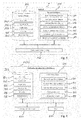
- Fig. 5 exemplarily and schematically shows a method of supporting the user of an electrically driven vehicle 4, wherein, in Fig. 5 , the method steps are exemplarily performed at a server side, e.g. at a server system 1 as illustrated in Fig. 2 .
- the server system 1 waits for a request from the user to be received via the network N through the communication means 130 (step S1).
- the server system 1 receives an monitoring mode activation request from the user via the communication means (step S2)
- the server system 1 initiates a process for risk monitoring for the user according to the monitoring mode activation request received from the user in step S1.
- the monitoring mode activation request may contain a user ID identifying the requesting user, authentication data for authenticating the user and the user's request, a vehicle ID identifying the vehicle 4 in which the user is traveling, and the risk monitoring items to be monitored.
- the monitoring mode activation request may further contain source HMI device information such as a source IP address of the HMI device used by the user (e.g. on-board unit 5 or mobile unit 7) and charging station preference parameters indicating user's preferences relating to booking of one or more charging stations.
- Some of the above-mentioned information may be also pre-registered in the memory means 120 of the server system 1 in advance by the user. In that case, the request does not necessarily need to include such information into the monitoring mode activation request.
- step S3 After the initiation of the risk monitoring process by activating the monitoring mode according to the monitoring mode activation request (step S3), the original process goes back to step S1 in order to wait for another request from the user such as a modified monitoring mode activation request or a monitoring mode deactivation request.
- the step S3 may additionally include a user authentication in order to check whether the requesting user subscribed the requested monitoring service or not, and it may further check whether the user ID is associated with the vehicle ID based on information stored in the memory means 120 of the server system 1.
- step S4 in which the server system 1 sends a response to the HMI device of the user for informing him about the result of step S3.
- the server system 1 may issue a response indicating that the received monitoring mode activation request has been received or even indicating whether the received monitoring mode activation request is granted or denied on the basis of the user authentication.
- step S5 it is determined whether the monitoring mode is activated or not, and if the result is no, the process ends (step S6). However, if the monitoring mode is activated (step S5 gives yes as a result), the process continues with step S7 in which vehicle information of the associated vehicle 4 is obtained from the vehicle 4 and/or from the memory means 120.
- step S7 can be realized in different ways.
- the server system 1 may send a request to the HMI device (e.g. on-board unit 5 or mobile unit 7) or to other in-vehicle equipment devices, which manages the vehicle information in the vehicle 4, so as to then receive the requested vehicle information from the vehicle 4 in response to the request.
- the HMI device or the vehicle may periodically send the vehicle information to the server system 1 without any request.
- the server system may then receive the vehicle information and use it to update the vehicle information 122 stored in the memory means 120 from which is may be obtained in step S7.
- the process continues with a step S8 of calculating the risk of occurrence of risk monitoring items specified in the received monitoring mode activation request.
- the risk monitoring items may include, for example, occurrence of a traffic jam, occurrence of a battery shortage, and the occurrence of a delayed arrival at the set destination, which may represent the location of a charging station for which a reservation has been made for a specific time slot.
- a quantified value which indicates the calculated risk for the occurrence of a risk monitoring item (such as a percentage level of risk of the occurrence of a risk monitoring item) or classified types expressing the level of the calculated risk for the occurrence of a risk monitoring item is output for each selected risk monitoring item.
- the risk calculation means 112 determines if there is a risk of the occurrence of a traffic jam on the route to the destination, or if there is the possibility that traffic jam will happen around the estimated passing time, based on the traffic information 123 (which may relate to real-time traffic information and/or statistical traffic information).
- the risk calculation means 112 determines the estimated battery consumption when traveling to the destination, e.g., based on the driving distance of the route from the current position and the position of the destination and estimated travelling time from the current position of the vehicle 4 to the destination position, the electricity mileage of the vehicle 4, the electricity devices usage of the electric devices (e.g. devices 12 and 13) of the vehicle 4 and/or the weather information 125.
- risk calculation means 112 determines the estimated travelling time from the current position of the vehicle 4 to the destination position and checks whether the vehicle can reach the destination on time based on the estimated travelling time and a current time.
- next step S9 it is determined by the risk monitoring means 111 whether one or more of the selected risk monitoring items have a calculated risk exceeding a specified threshold. If the calculated risk for each selected risk monitoring item is below the respective specified threshold (step S9 returns no), the process gets into the waiting phase and then repeats the steps S5 to S9 after the waiting phase.
- a timer is set to wait (step S10) and the server system 1 waits (step S11) for the timer expiration until the next round of the risk check (S11). Accordingly, the steps S5 to S9 may be performed repeatedly or even periodically in order to dynamically monitor all selected risk monitoring items.
- step S9 returns yes
- the process goes to the next step S12 in which the solution suggestion means 115 determines one or more recommended solutions available for trying to avoid the occurrence the respective risk monitoring item for which the calculated risk exceeds the specified threshold.
- the solution suggestion means 115 may calculate one or more alternative routes from the current position to the destination position and the estimated travelling time for the calculated alternative routes, and, set the alternative route which requires the smallest travelling time and/or the smallest battery consumption among all calculated alternative routes and which requires less travelling time than the currently set route as the recommended solution.
- the solution suggestion means 115 may perform a search, on the basis of the charging station information 124 and the vehicle information 122, if there exists an available charging station which can be reached by the vehicle 4 with the remaining battery level. If one or more such available charging stations can be identified on the basis of the charging station information 124 and the vehicle information 122, the solution suggestion means 115 can set battery charging as one of the recommended solutions.
- the solution suggestion means 115 can calculate one or more alternative routes from the current position to the destination position and check whether there exists an alternative route which require less battery consumption leading to a decreased risk of the occurrence of a battery shortage. If such an alternative route is found, the solution suggestion means 115 can also set the detour route as another option of the recommended solutions.
- the solution suggestion means 115 may calculate one or more alternative routes from the current position to the destination position and the estimated travelling time for the calculated alternative routes, and, set the alternative route which requires the smallest travelling time among all calculated alternative routes and which requires less travelling time than the currently set route as the recommended solution.
- the solution suggestion means 115 can set booking update (e.g., rebooking of the reservation at the charging station, cancellation of the charging station reservation, making a new reservation at another closer charging station, or the like) as one of the recommended solutions.
- booking update e.g., rebooking of the reservation at the charging station, cancellation of the charging station reservation, making a new reservation at another closer charging station, or the like
- step S9 the server system 1 sends data indicating the risk information calculated in step S8 and the recommended solutions determined in step S12 to the HMI device of the user and in order to notify the user about the detected risk(s) and the corresponding recommended solutions via the human machine interface means 240. Then, under the condition that no monitoring mode deactivation request is received at the server system 1, the process goes to the waiting phase (steps S10 and S11) in order to repeat steps S5 to S9 and potentially steps S12 and S13.
- the main loop is triggered by a timer, but it is also possible to be triggered by events, i.e. by event-triggering.
- events i.e. by event-triggering.
- the server system 1 may immediately trigger the risk monitoring process after receiving the traffic accident information. By doing so, the server system 1 can advantageously dynamically react to situation changes even more quickly.
- the server may receive other types of requests in the step S2. For example, if the server system 1 receives a monitoring mode deactivation request relating to one or more selected monitored risk items from the corresponding user, the server system 1 may set the corresponding risk monitoring mode flag to false so that the activated risk monitoring process ends for the deactivated monitored risk items because the step S5 gives the result no.
- a configuration update request is issued when the user would like to change the configuration of the services and an action request is issued when the user would like the server system 1 to perform a specific action such as making a reservation/cancellation for a charging station or calculating an alternative route.
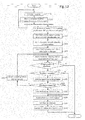
- the HMI device (or an independent HMI device such as a mobile unit 7) may handle the interaction with the user and the server system 1 according to the exemplary and schematic method for supporting the user of an electrically driven vehicle 4 as illustrated in Fig. 6 .
- the HMI control means 214 checks whether a driving assistance application comprising a risk monitoring service, such as a navigation application as one potential example of the applications which may contain the risk monitoring service, is launched by the user or not. If not (S100 returns No), the process continues to repeat step S100 until the risk monitoring service is activated.
- a driving assistance application comprising a risk monitoring service
- a navigation application as one potential example of the applications which may contain the risk monitoring service
- step S100 returns yes
- the human machine interface means 240 displays a main screen of the application (step S101) to the user and provides the user with the possibility of selecting the monitoring mode including the possibility of selecting monitoring mode parameters and/or the possibility of selecting one or more risk monitoring items. If the user selects the monitoring mode in the application (step S102 returns yes), the process goes to the next step (step S104). Otherwise (S102 returns no), the HMI device may perform other operations and goes back to step S101 of displaying the main screen.
- step S102 returns yes
- the vehicle status check means 211 obtains the vehicle information 222 such as the vehicle ID, the battery status and the electric device usage status in step S104, and obtains the user information 221 such as the user ID and the configuration parameters stored for the user (step S105).
- the HMI device via the human machine interface means 240 shows a summary screen indicating a summary of the obtained configuration parameters of the monitoring mode in the display means and ask the user's confirmation (step S106).
- Fig. 7 exemplarily shows a summary screen 500 which is shown to the user via the display means of the human machine interface means 240.
- the summary screen exemplarily comprises screen buttons 501 and 502 allowing the user to confirm or deny the shown summary of currently selected configuration parameters.
- a screen field 503 there are shown the plural available risk monitoring items including occurrence of traffic incidents such as traffic accident, traffic jam, and road works, occurrence of a battery shortage, and occurrence of a delayed arrival time.
- reference numeral 504 relates to the shown information regarding the currently set destination (e.g. a charging station at a city A) and reference numeral 505 relates to the shown information regarding the set intended arrival time at the destination to be used for the risk calculations in connection with the risk monitoring item of the occurrence of a delayed arrival.
- a field 506 of the summary screen the user may select if and which electric devices shall be monitored regarding the estimation of the electric power consumption which may affect the risk of the occurrence of a battery shortage prior to the arrival at the destination.
- a field 507 additionally provides the optional functionality of setting preferences for the operation of the solution suggestion means 114.
- Reference numeral 508 relates to the shown information regarding the currently available energy level of the battery 10.
- the summary screen 500 shows a confirmation request (buttons 501 and 502) to the user and the currently configured parameters of the monitoring mode, such as the risk monitoring items 503 with the selected risk threshold for the notification, the electricity usage options 506 and the solution preference 507.
- the summary screen 500 allows the user to change the parameters. For example, the user can select one or more of the listed risk monitoring items 503 with the risk threshold. This risk threshold is used to judge if the calculated risk should be notified to the HMI device or not.
- the risk monitoring item option of "Arrival Time" is selected in field 503, the destination 504 and the required arrival time 505 need to be set. If the destination corresponds to a reserved charging station (as in Fig.
- the HMI device can also set the required arrival time to the reserved time of the charging station by referring to the charging station booking information 224 in the memory means 220.
- the user can select one or more of the listed electric usage options 506, which are used in the server for calculation of the battery consumption.
- the user can further select one of the solution preference options 507.
- the item selected in field 507 is then used for determining the priority of solutions to be recommended.
- step S107 After confirmation by the user via button 501 (step S107), the configuration parameters are stored in the memory means 220 and/or sent to the server system 1 for the risk monitoring mode.
- step S107 if the user selects button 502 of the summary screen 500 (step S107 returns no), the process continues with step S101 to show again the main screen. If the user selects button 501 of the summary screen 500 (step S107 returns yes), the HMI control means 213 sends a monitoring mode activation request to the server system 1 via the communication means 230 through the network N (which may be received at the server system 1 according to step S1 described above) in the step S108.
- step S109 After the activation request is sent to the server system 1 (step S108), the HMI device is supposed to receive a response from the server system 1 (step S109), e.g. a response sent in step S4 described above. If the HMI device has not received such a response for a certain period of time (step S109 returns no), the human machine interface means 240 notifies the user about a communication error (step S113) and goes back to the main screen of the application (step S101).
- step S109 returns yes
- the process goes to the next step S110 and checks if the activation is successful or not on the basis of the received response. If the request failed or was denied (step S110 returns no), the human machine interface means 240 displays the reason of the failure or denial (step S114), and goes back to the main screen of the application (step S101). Otherwise, if step S110 returns yes), the human machine interface means 240 shows the main screen 550 including an additional icon 509 specifying that the monitoring mode is activated (step S111). After the step S111, the process continues with the risk monitoring process in step S112, the risk monitoring process being described in more detail with reference to Fig. 9 below.
- Fig. 8 schematically illustrates an example of the main screen 550 with an additional monitoring mode icon 509 illustrating that the monitoring mode is activated. Furthermore, the main screen exemplarily shows information 504 regarding the destination, information 510 regarding the remaining distance to the destination according to a currently set navigation route and information 511 regarding the currently estimated arrival time.
- a field 512 shows navigational data including a navigational map and route information (such as an arrow 513).
- Fig. 9 schematically and exemplarily illustrates a risk monitoring process according to an embodiment of the present invention.
- the HMI device waits for a risk notification from the server system 1 in step S120 (e.g. a notification sent in step S13 described above).
- the HMI device receives the risk notification together with recommended solutions from the server system 1 in step S120.
- the HMI device updates the monitoring mode icon 509 for notifying the current risk status to the user (S122).
- the icon's color can be changed depending on the risk level, or the risk level can be explicitly written adjacent to the icon 509. This risk status may be kept for a certain period of time. If there is no update for during the period, the risk status may be reset.
- step S122 the HMI control means 214 determines whether the risk level is higher than a previous risk level which was already informed to the user. If step S122 returns no, the HMI control means 214 refrains from informing the user of the risk information and goes back to the step S120. By this optional step, it can be avoided to unnecessarily bother the user by displaying the similar risk information. However, if the result of step S122 is yes, the human machine interface means 240 informs the users of the new risk information (see e.g. reference numeral 514 in Fig. 10 ) as well as the recommended solutions via a display screen and/or other types of HMI output such as voice output (step S123).
- Fig. 10 illustrates an example of a risk informing screen 600 of the human machine interface means 240 displaying the risk information 515 and the recommended solutions 516.
- the monitoring mode icon 509 specifies the risk status by displaying the risk percentage 514.
- the risk information 515 is displayed as a warning to the user.
- the displayed risk information may include the risk type (here battery shortage, for example), which corresponds to one of the specified monitoring items in the step S106, the risk level, the main reason of the risk or the like.
- recommended solutions 516 are also displayed in the bottom of the risk informing screen 600.
- the recommended solutions 516 may include multiple recommendations.
- the risk informing screen 600 shows one of them initially (here: "1. Detour Route", including information on the best candidate of available alternative routes such as distance, estimated arrival time, and the changed risk level associated with the alternative route) and allows the user to display the other solutions.
- Detour Route including information on the best candidate of available alternative routes such as distance, estimated arrival time, and the changed risk level associated with the alternative route
- tab windows are exemplarily used.
- the displaying order of the multiple recommendations can be determined by the solution preference specified by the user in the step S106.
- Fig. 11 exemplarily illustrates a modified risk informing screen 600' when the user selects the battery charge (second recommendation "2. Battery Charge” in field 516 of the risk informing screen 600 in Fig. 10 , resulting in displaying of the modified field 516' (additionally allowing the user to initiate a search for charging station candidates).
- the driver assistance service 517 is kept displaying not to disturb the on-going service.
- the risk information 515 and the recommended solutions 516 are displayed automatically, but it is also possible that the HMI device only gives a notification to the user by a short-time display or a voice output and lets the user touch the menu or the monitoring icon in order to see more details.
- buttons to request an action or to ignore this warning and the recommendations there are provided buttons to request an action or to ignore this warning and the recommendations. If the "ignore" button is selected (step S124 returns No), the warning screen is closed and the main screen is displayed again (step S101). If one of the recommended action buttons is selected (step S124 returns yes), the HMI device sends a corresponding action request to the server system 1 (step S125). After that, the HMI device may perform a selected action process (step S126) and reset a warning notification history if the risk is resolved. If the step S125 is failed for any reason, the HMI device does not reset the warning notification history. Then the process goes back to step S120.
- the charging station search request may be specified.
- Fig. 12 shows an exemplary server operation method according to an embodiment of the present invention, when receiving an action request concerning the charging station search (which may be selected in field 516') and
- Fig. 13 shows the corresponding HMI device operation method according to an embodiment of the present invention.
- step S20 After the server system 1 receives an action request concerning the requested charging station search (step S20) while waiting for a user request (step S1), the server system initiates the requested process for the charging station search operation.
- step S21 the charging station booking control means 116 first obtains the latest available information on charging station availability in the relevance area on the basis of information 124 stored in the memory means 120 (which may be automatically and periodically updated) and/or on the basis of information received and/or requested from the charging station center 3.
- the relevance area may be, for example, an area defined by a distance that can be still travelled with the vehicle 4 based on the remaining battery level of the battery 10, an area defined by a specified time period, wherein the vehicle 4 can reach points within the area during the specified period of time from any point on the currently set route, the area defined by a specific city, or the like. Also, the relevance area can be specified by the user according to the user preference when sending the action request relating to the charging station search.
- the server system 1 may also obtains user-specific charging point information (step S22), which can be pre-assigned by the user, e.g. for registering private charging points in advance, such as a private charger at the user's home, for example.
- the charging station score calculating means 114 calculates, for each charging station candidate, a score value on the basis of the user preference (step S23).
- the respective score may be calculated as one value based on the solution preference specified in the activation request, or may be calculated as multiple values which are relevant to solution preference items, respectively, such as quick arrival, less cost and certainty (see field 507 in Fig. 7 ).
- the server system 1 sends information on one or more of the charging station candidates together with the information on their calculated scores (step S24) via the network N to the HMI device of the user.
- the human machine interface means 240 provides the received information to the use (step S131), e.g., in the order of the calculated scores.
- Fig. 14 exemplarily and schematically shows a charging station candidate screen 700 displaying the charging station candidates at the human machine interface means 240.
- the charging station candidate screen 700 shows a list 701 of the charging station candidates on which information was received from the server system 1.
- the list 701 is exemplarily sorted by the calculated score but the candidates may also be listed according to other criteria, such as certainty, quick arrival and low cost.
- the charging station candidate screen 700 exemplarily shows the list only partially due to a limitation of the display size, but provides the user with the functionality of selecting an alternative view showing all possible candidates by selecting the "Show All" button 702.
- the candidate list 702 further provides the user with the functionality of selecting one of the listed charging station candidates.
- the field 703 indicates the name of the selected charging station candidate, the location of the selected charging station candidate, the available facilities at the selected charging station candidate (number of charging units and types of charging units), the selectable booking options for the selected charging station candidate, the distance to the selected charging station candidate and the estimated arrival time at the selected charging station candidate, the overall distance to the final destination from the current position via the selected charging station candidate, the recommended charging time at the selected charging station candidate and the estimated arrival time to the final destination from the current position via the selected charging station candidate taking into account the charging time.
- the available facilities at the selected charging station candidate may specify, for example, how many charging slots are available for each type of charger, such as quick charger (high voltage) and normal charger (domestic voltage).
- the selectable booking options specify booking options that are selectable by the user for the selected charging station candidate. For example, if quick chargers and normal chargers are available at the selected charging station candidate, there may be provided the selectable options of charging with a quick charger, charging with a normal charger and no booking.
- the recommended charging time may be calculated based on the charger type and the required battery level which is minimally necessary to be able to reach the destination without further charging. Accordingly, if a specific charging level of the battery 10 (e.g. 60%) is estimated to be sufficient for being able to reach the destination, the recommended charging time is set as the time that is required to charge the battery 10 up to the specific charging level based on the selected charger type. For precautionary reasons, it is further possible to recommend a charging time which is required to charge the battery 10 up to a level corresponding to the specific charging level plus a tolerance (e.g. plus 5%). Furthermore, field 703 exemplarily shows also the costs for the charging operation at the at the selected charging station candidate taking into account the recommended charging time (e.g. €3) and how the battery 10 is going to recover (e.g. 30%->60%) by the recommended charging operation.
- the recommended charging time e.g. €3
- the charging station candidate screen 700 comprises a select button 704 and a cancel button 705 allowing the user to select the selected charging station candidate for booking, i.e. in order to proceed with making a reservation for the selected charging station candidate (step 132 returns yes), or to cancel the booking operation (step 132 returns yes). In the latter case, a cancellation request is sent to the server system 1 (step S133) and the process ends.
- step S132 of determining whether a charging station candidate was selected returns yes, it is determined for the selected charging station candidate whether booking is required or not. If not, the HMI control means 214 by means of the communication means 230 sends a message to the server system 1 informing the server system 1 about the user's selection (step S135) and continues with step S141 described later.
- step S132 returns yes, the process continues with step S136 of determining booking parameters for the booking operation.
- Fig. 15 exemplarily and schematically illustrates an example of a booking parameter screen 800 enabling a determination of booking parameters on the basis of a user input.
- booking parameters may be obtained from the booking information 224 stored in the memory means 220.
- the booking parameter screen 800 comprises a field 801 relating to the booking parameter determination showing information of the charging station selected for booking (similar to the information displayed in field 703) and, additionally, displaying the time slot for which a reservation is to be made at the selected charging station, wherein the charging start time and the charging end time are configurable by user input.
- recommended parameters such as the recommended charging start time and the recommended charging end time, are set by default.
- the booking parameter screen 800 of Fig. 15 also displays a field 802 showing the user information to be used for the booking, such as the user ID, the authentication data for the charging station booking and payment data like credit card information.
- the field 802 can be modified by the user in an edit mode initiated by operation of the button 805: "Edit information".
- the user can confirm the currently displayed information in order to initiate the booking operation on the basis of the determined booking parameters.
- the “Back to the list” button 804 the user can go back to the charging station candidate screen 700 when he desires to select another charging station candidate for booking.
- the HMI control means 214 by means of the communication means 230 sends the information on the charging station information together with the determined booking parameters to the server system 1 (step S137).
- the charging station booking control means 116 determines whether a charging station candidate for booking is specified by the received data or not (step S26). If it is not specified (step S26 returns no; e.g. in case of receipt of a cancellation request), the process ends.
- step S26 determines whether the booking option is specified or not (step S27). If not specified, the process goes to the step S32. Otherwise, the charging station booking control means 116 makes a reservation at the specified charging station (step S28) through the network N via a booking interface of the charging station center 3 on the basis of the determined booking parameters by using the user information such as the user ID and authentication data of the booking system and payment information (such as, e.g., credit card information).
- the user information may be received from the HMI device when sending the booking information or it may be pre-registered in the user information 121 stored in the memory means 120 of the server system 1.
- step S29 of determining whether the booking was successful returns no
- a booking failure message is sent to the HMI device in order to notify the user (step S30) and goes back to the step S25.
- the charging station booking control means 116 by means of the communication means 130 sends a booking confirmation message to the user (step S31) and updates the destination information of the user by setting the location of the newly booked charging station as the intermediate destination (step S32) for route calculation and navigation, and also for the destination used for risk monitoring items such as traffic jam, delayed arrival or battery shortage.
- the risk calculation means 112 calculates the risk levels for selected risk monitoring items, e.g.
- step S33 up to the charging station as a destination and/or up to the final destination by taking into account the battery charging in the newly booked charging station (step S33), and the calculation results are sent via the communication means 130 to the HMI device for notifying the user about the new calculated risk levels (step S34). Then, the booking process ends at the system server 1.
- the action request concerning the requested charging station search of step S20 may also be received at the server system 1 during a time period in which the monitoring mode is deactivated.
- the search for and selection of charging station candidates and the booking of a selected charging station candidate can be handled similarly.
- the communication means 230 of the HMI device receives a booking result message from the server system 1 (step S138). If the received booking result message indicates a booking failure (S139 returns no), the human machine interface means 240 notifies the user about the booking failure information via a screen and/or a voice output (step S140). On the other hand, if the received booking result message indicates a booking success (S139 returns yes), the human machine interface means 240 notifies the user about the booking success information via a screen and/or a voice output (step S141).
- the communication means 230 receives the updated risk information from the server system 1 (step S142) which was sent in step S34, and then updates the monitoring mode icon on the screen of the human machine interface means 240 notifying the user about the current risk status (step S143). Accordingly, the charging station operation request of the user is accomplished as a selected action process (e.g. step S126), and the HMI device process goes to S127 of Fig. 9 .
- the risk monitoring process is mainly performed at the server side while information is received from the vehicle-side, but the present invention is not limited to server-sided risk monitoring but it is also possible to provide embodiments according to which the HMI device such as an on-board unit or a mobile HMI unit which is communicably connectable with the vehicle monitors the risk by repeatedly or even periodically, potentially obtaining information such as weather information, traffic information, and/or charging station information through the network N.
- the HMI device such as an on-board unit or a mobile HMI unit which is communicably connectable with the vehicle monitors the risk by repeatedly or even periodically, potentially obtaining information such as weather information, traffic information, and/or charging station information through the network N.
Abstract
Description
- The present invention relates to a system for supporting a user of an electrically driven vehicle such as an electric vehicle or a plug-in hybrid electric vehicle.
- Electric vehicles (EV) and plug-in-hybrid electric vehicles (PHEV) are becoming more and more popular because of their environmental and economical perspectives. Such electrically driven vehicles need to be equipped with a sufficiently charged battery in the vehicle. Otherwise, there may occur a risk that the remaining driving distance becomes insufficient or even that the battery may run out. When becoming aware of the risk of a battery shortage, the user needs to find a remedy for the situation and, currently, charging of the battery is then required which can be performed by the user at a public charging station or at a parking space with charging station equipment. However, since it currently takes a long time to charge the battery, unlike fuelling a car having a combustion engine, if a user finds the charging station occupied, the user may need to wait for hours or to find another place for charging.
- For drivers and/or co-drivers of electric vehicles or plug-in hybrid electric vehicles (in the following sometimes referred to as users), the available remaining driving distance and a potential risk of a battery shortage on the way are among the main worrying issues, especially since the battery capacity is typically limited and, currently, even if the battery is fully charged, the maximum distance in the best condition is typically less than 200km. Such poor battery capacity is one reason that increases the risk of the battery shortage. In order to have a sufficient available remaining driving distance and in order to avoid the occurrence of a battery shortage on the way, users of electric vehicles or plug-in hybrid electric vehicles need to sufficiently charge the battery and keep attention on the power level. However, because of the time that is currently necessary for charging the battery, the users may often not rely on usability of public charging stations, when needed. In view of such problems, there have been considered charging-station booking systems allowing users of electric vehicles or plug-in hybrid electric vehicles to make reservations for charging stations in advance of a planned trip.
- For example,
US 2011/0032110 A1 proposes an electric power amount information output device for a vehicle comprising a control section checks, prior to the trip after setting an departure point and a destination point, whether a remaining electric power amount of a battery of a motor-driven vehicle at the departure point is less than a total electric power amount required for the vehicle to travel to the destination point. The control section drives an output section to output insufficiency information indicating that the remaining electric power amount of the battery is insufficient, if the remaining electric power amount is less than the required total electric power amount. - However, since the proposed device of
US 2011/0032110 A1 is merely relating to an operation at the departure point, prior to the actual trip, for reserving a charging station statically but is not handling the reservation dynamically during travelling, the inventors of the present invention have considered that there remains a problem that the user of the electric vehicle or the plug-in hybrid electric vehicles may still suffer from the risk of a battery shortage due to unexpected incidents and influences such as traffic conditions, including traffic accidents, traffic jams and road work, and/or weather conditions that may occur dynamically during travelling. In particular, such static charging station reservation planning as proposed inUS 2011/0032110 A1 does not provide any capacities for handling dynamic situation changes. For example, it is considered by the inventors that if the user is caught in a heavy traffic jam, there may be the increased risk of a battery shortage occurring in the traffic jam and/or there may occur the risk that the traffic jam leads to a delay which may make it impossible to reach a reserved charging station within the reserved time slot. - In accordance with the above, it is an object of the present invention to provide an improved system for supporting a user of an electrically driven vehicle which may help further reducing the risk that the user of the electric vehicle or the plug-in hybrid electric vehicle may still suffer from a battery shortage or that the remaining driving distance becomes insufficient. In view of the above-mentioned object of the present invention, a system for supporting a user of an electrically driven vehicle according to
claim 1 is proposed. Dependent claims relate to preferred embodiments of the present invention. - According to an aspect of the invention, there is proposed a system for supporting a user of an electrically driven vehicle, comprising position information obtaining means for obtaining, during traveling, position information indicating a position of the vehicle, electric power amount estimating means for estimating, during traveling, a remaining electric power amount of an electric power source of the vehicle, shortage risk estimating means for estimating, during traveling, an estimated risk of electric power amount shortage on the basis of the estimated remaining electric power amount, and notifying means for notifying a user in case the estimated risk of electric power amount shortage estimated by the shortage risk estimating means exceeds a predetermined threshold.
- Accordingly, it is the underlying concept of the present invention that the system may provide improved assistance to the users of electric vehicles or plug-in hybrid electric vehicles - not only at the departure point but also during traveling - so that it advantageously becomes possible to assist the user under dynamically changing situations during the trip. This advantageously improves the user assistance since it becomes possible to warn the user dynamically about changing situations which may unexpectedly occur during traveling and which may lead to previously unanticipated risks of the occurrence of a battery shortage and/or which may lead to a situation in which the remaining driving distance becomes insufficient.
- Accordingly, the present invention advantageously makes it possible to dynamically inform the user about a potentially dynamically occurring risk of an occurrence of a battery shortage during traveling or a dynamical increase of a risk of occurrence of a battery shortage during traveling, advantageously allowing the user to dynamically react during travelling. Specifically, plural factors may dynamically affect the power consumption of the electrically driven vehicle during travelling such as dynamic usage of electric devices such as audio devices, air conditioning devices etc., dynamic usage of vehicle lights, dynamically occurring traffic conditions such as traffic accidents, road work, traffic jams, or even changing weather conditions (e.g. heat may lead to the necessity of using air conditioning and cold conditions may lead to the necessity of usage of heating devices, occurring fog may lead to the necessity to turn on additional lights, rain may lead to the necessity of using a wiper, snow may lead to a significantly different average speed and traveling time, etc.). The present invention advantageously helps to assist and support the user dynamically during driving.
- According to preferred embodiments of the present invention, the system of the invention may be embodied by an on-board unit and/or a server (being communicably connected to electric vehicles or to an in-vehicle device) which is communicably connected to a support station infrastructure such as e.g. a charging station infrastructure and to a traffic information center by any media directly or indirectly, the server and/or on-board unit having means for collecting the vehicle battery information, vehicle current location, vehicle destination position, support station availability information such as charging station availability information, weather condition and/or traffic information. The server and/or on-board unit may repeatedly or even periodically monitor a risk of battery shortage dynamically based on the obtained information and, once the risk is detected, the server and/or on-board unit may preferably suggest to the user the favorable support station candidate(s) such as charging station candidate(s) and/or, if the support station is a charging station, the favorable charging operation timing on the way autonomously. By doing so, compared to the prior art, the driver receives support that allows to timely and appropriately react to risks that are dynamically caused during traveling by various potential dynamically changing situations.
- It is to be noted that while the present invention mainly described above and below with respect to support stations such as charging stations, where a user of an electrically driven vehicle can charge up a battery of the vehicle, it is further possible that a support station in the sense of the present invention represents a location where exchangeable charged batteries are available so that the user may exchange the battery of the vehicle with an exchangeable charged battery at the support station. Then, support station availability information may include information such as position of the support station, opening hours of the support station, availability of charged batteries at the support station (e.g. information indicating available numbers and/or available types of charged batteries, available support personnel for performing an exchange of the battery, etc.). In the case of charging stations, the support station availability information may include information such as position of the support station, opening hours of the support station, availability of charging units for charging the vehicle, number of available charging units for charging the vehicle types of available charging units for charging the vehicle (e.g. normal charging units or quick-charging units), available time slots for charging a vehicle, possibility of making a reservation for charging units at specific time slots, etc. Of course, the term support station in the sense of the present invention may further relate to location where a user has both possibilities of either charging the battery of the vehicle or exchanging the battery of the vehicle with a charged battery. A support station may further even be a service station which can be contacted by the user in order to order a battery exchange service at a pre-determined location which can be reached by the user.
- Some of the preferred aspects and embodiments of the present invention shall be mentioned below.
- According to a preferred aspect of the present invention, the shortage risk estimating means is preferably configured to estimate the estimated risk of electric power amount shortage on the further basis of information indicating dynamic conditions affecting the power consumption of the vehicle during traveling, said information particularly preferably including at least one of traffic information, weather information and vehicle information. This advantageously improves the user assistance since it becomes possible to warn the user dynamically about changing situations which may lead to previously unanticipated risks of battery shortage, e.g., due to dynamic changes of the situation affecting the remaining electric power amount, such as usage of electric devices of the vehicle, weather conditions (e.g. activated lights necessary due to changing weather conditions, air conditioning becomes necessary etc.) or traffic conditions (such as longer travelling distances and/or travelling times due to road works, traffic accidents or traffic jam).
- According to another preferred aspect of the present invention, the system preferably further comprises required electric power amount estimating means for estimating, during traveling, a required electric power amount required for traveling with the vehicle from the determined position to a destination position, the shortage risk estimating means being preferably configured to estimate the estimated risk of electric power amount shortage further on the basis of the estimated required electric power amount. This has the advantage that the risk for occurrence of a battery shortage during the trip to the destination position (as a final destination or an intermediate destination such as the destination of a support station such as a charging station) can be dynamically and reliably determined based on information indicating the required electric power amount required for traveling with the vehicle from the determined position to the destination position, which may dynamically change due to unexpected incidents such as traffic incidents on the current route such as road work, accidents or traffic jams or increased power consumption of electric devices due to changed weather conditions (e.g. air conditioner required if it becomes hot, lights required if there is fog, rain or snow, wiper operation required due to rain, snow or the like).
- According to another preferred aspect of the present invention, the system preferably further comprises traffic information acquiring means for acquiring traffic information. Then, the required electric power amount estimating means is preferably configured to estimate the required electric power amount on the basis of traffic information acquired by the traffic information acquiring means, and/or the shortage risk estimating means is preferably configured to estimate the estimated risk of electric power amount shortage on the basis of traffic information acquired by the traffic information acquiring means. This provides the advantage that the determination of a risk of occurrence of a battery shortage or other potential risk monitoring items such as, e.g., occurrence of a delayed arrival at a destinations such as a booked support station such as a booked charging station, can be more reliably and dynamically performed by taking into account potential risk increasing effects coming from dynamically changing traffic conditions during travelling. Further preferably, the traffic information comprises at least one of traffic jam information, traffic accident information, road work information, traveling time information to advantageously allow for taking into account potentially dynamically changing traffic conditions such as road works, traffic jams and traffic accidents.
- Further preferably, the system may further comprise route calculation means for calculating travel routes from the determined position to the destination position. Then, when the shortage risk estimating means estimates that the estimated risk of electric power amount shortage exceeds a predetermined threshold due to traffic conditions on a current route which are indicated in the traffic information, the route calculation means is preferably configured to calculate one or more alternative routes from the determined position to the destination position, and the required electric power amount estimating means is preferably configured to estimate, preferably for each of the one or more alternative routes, an alternatively required electric power amount required for traveling with the vehicle from the determined position to the destination position along the respective alternative route. This may further improve the support for the user since it becomes possible not only to warn the user but additionally provide recommended solutions involving recommendations for potential alternative routes that may help avoiding the occurrence of a battery shortage prior to arriving at the destination. The system may further have the capability of warning the user if no suitable alternative route to the destination or to a support station such as a charging station can be found and, additionally, may suggest an alternative route in such a situation which guides the user to a safe place as an alternative destination (such as a road shoulder). It may further assist the user in calling for roadside assistance prior to or upon arrival at the safe place.
- Further preferably, the shortage risk estimating means is configured to estimate, for each of the one or more alternative routes, a respective estimated risk of electric power amount shortage on the basis of the remaining electric power amount and the alternatively required electric power amount. This advantageously provides the possibility of evaluating the recommended routes in view of their potential for avoiding the occurrence of a battery shortage prior to arriving at the destination.
- Further preferably, the notifying means is further configured to notify the user of the vehicle about alternative routes for which the respective estimated risk of electric power amount shortage estimated by the shortage risk estimating means is below the predetermined threshold. Then, the user can appropriately react to the informed risk by selecting another route. If no such route is found, the notifying means may notify the user about an alternative route to a safe place such as a road shoulder.
- Further preferably, the system may further comprise delay risk estimating means for estimating, during traveling, an estimated risk of a delayed arrival time at the destination position on the basis of an intended arrival time being specified for the destination position and traffic information acquired by the traffic information acquiring means, in particular wherein the destination position preferably represents a position of a specific support station such as a specific charging station and the intended arrival time preferably represents an intended arrical time at the support station such as e.g. a booked charging start time for the vehicle at the specific charging station. This advantageously adds a further possible risk monitoring item in addition to monitoring the risk of a battery shortage which is particularly advantageous if the destination is a booked support station such as a booked charging station (e.g. as a potential intermediate destination) for which a delayed arrival may mean that the reservation is lost and the battery shortage risk might be indirectly increased since the charging operation cannot be performed as planned at departure.
- Further preferably, the notifying means may be further configured to notify the user of the vehicle in case the estimated risk of a delayed arrival time estimated by the delay risk estimating means exceeds a predetermined threshold. Then, the user can appropriately react to the informed risk by trying to find another faster or at least more energy-efficient route or rebook the charging station in advance (via the HMI device or also manually, e.g., via telephone or the internet).
- According to another preferred aspect of the present invention, the system preferably further comprises support station information acquiring means for acquiring support station information such as charging station information preferably comprising at least one of position information indicating positions of one or more support stations such as one or more charging stations and availability information indicating an availability status of one or more support stations such as one or more charging stations. This enables to provide the user with support station information which may help to better react on the detected risk of a battery shortage.
- Further preferably, the required electric power amount estimating means may be configured to estimate, preferably for each of one or more support stations indicated in the support station information, a required electric power amount required for traveling with the vehicle from the determined position to the position of the respective support station, and the shortage risk estimating means is preferably configured to estimate, preferably for each of one or more support stations indicated in the support station information, an estimated risk of electric power amount shortage, when traveling from the determined position to the position of the respective support station. This further improves the support for the user since the user can be informed additionally on the risk of a battery shortage when heading towards one of the support stations in order to avoid the initially detected risk of a battery shortage.
- Further preferably, the notifying means may be configured to notify the user of the vehicle about support stations such as charging stations for which the estimated risk of electric power amount shortage estimated by the shortage risk estimating means is below a predetermined threshold. Then, the user may appropriately select the potential support stations for avoiding the dynamically detected risk of a battery shortage. If no such potential support station is found, the notifying means may be configured to notify the user of the vehicle about potential alternative destinations such as a safe place (e.g. a road shoulder) and/or a place where roadside assistance is available (e.g. for ordering a battery exchange).
- Further preferably, the system may further comprise support station booking support means being configured to support booking of support stations such as charging stations that are available for booking operations via a communication network. This provide the advantage that the user is enabled to directly initiate booking or re-booking of a charging station or another support station if there is dynamically detected a risk of a battery shortage or a delayed arrival.
- In particular, one or more of the following features may advantageously support the user when a risk is dynamically detected. Further preferably, the support station booking support means may be configured to issue a request for reservation directed to one of the support stations such as charging stations indicated in the support station information, in particular when the shortage risk estimating means estimates that the estimated risk of electric power amount shortage exceeds a predetermined threshold. Further preferably, the support station booking support means may be configured to issue a request for cancellation of a reservation directed to a charging station or another support station indicated in the support station information, in particular when the estimated risk of electric power amount shortage for traveling with the vehicle from the determined position to the position of the respective charging station or the other support station exceeds a predetermined threshold.
- The system may further comprise a roadside assistance requesting means configured to issue a request for roadside assistance at an alternative destination e.g. at a safe place such as a road shoulder, which can still be reached on the basis of the remaining battery level, in case the risk of a battery shortage is detected and no suitable alternative routes or available support stations such as charging stations can be found in order to prevent the occurrence of the battery shortage. If roadside assistance (such as e.g. a battery exchange) is requested at the alternative destination, the route calculation means may calculate a route to the alternative destination and the notifying means may guide the user along the calculated route to the alternative destination.
- According to another preferred aspect of the present invention, the system preferably further comprises weather information acquiring means for acquiring weather information. Further preferably, the required electric power amount estimating means may be configured to estimate the required electric power amount on the basis of weather information acquired by the weather information acquiring means, and/or the shortage risk estimating means may preferably be configured to estimate the estimated risk of electric power amount shortage on the basis of weather information acquired by the weather information acquiring means. This provides the advantage that the determination of a risk of occurrence of a battery shortage or other potential risk monitoring items such as, e.g., occurrence of a delayed arrival at a destinations such as a support stations such as a booked charging station, can be more reliably and dynamically performed by taking into account potential risk increasing effects coming from dynamically changing weather conditions during travelling (e.g. air conditioner required if it becomes hot, lights required if there is fog, rain or snow, wiper operation required due to rain, snow or the like).
- According to another preferred aspect of the present invention, the system preferably further comprises electric device usage information monitoring means for monitoring, during traveling, electric device usage information indicating the usage of electric devices of the vehicle being electrically driven by the electric power source. Further preferably, the shortage risk estimating means may be configured to estimate the estimated risk of electric power amount shortage on the basis of electric device usage information determined by the electric device usage information monitoring means. This advantageously improves the determination if there is a risk of battery shortage since it becomes possible to perform the dynamical determination on the basis of other potential risk increasing influences (such as activated radio, air conditioner, lights, communication means, vehicle sensors or the like, which affect the speed of battery power level reduction and may also ne dynamically activated or deactivated by the user). For example, after the user activates an electric device during travelling, such as e.g. the air conditioner, there may be the possibility that the risk of a battery shortage prior to arriving at the destination dynamically occurs after activation of the electric device.
- It is important to note that the system according to the invention and its preferred aspects as described above can be realized in different forms. Basically, it can be provided by one or more apparatuses installed at or being directly connected to the vehicle, it can be provided by a server system which is directly or indirectly communicably connected to the vehicle and monitors the vehicle during traveling on the basis of received information from the vehicle, or it can be provided by a combination of the above mentioned apparatuses installed at or being directly connected to the vehicle and a server system which is directly or indirectly communicably connected to the vehicle and monitors the vehicle.
- Specifically, according to an aspect of the present invention, the system may comprise an on-board apparatus being mountable to the vehicle. Then, the on-board apparatus may comprise at least one of the position monitoring means, the required electric power amount estimating means, the electric power amount estimating means, and the shortage risk estimating means. Alternatively, according to another aspect of the present invention, the system may comprise an external apparatus, such as a server or a server network, being communicably connectable with communication means of the vehicle. Then, the external apparatus may comprise at least one of the position monitoring means, the required electric power amount estimating means, the electric power amount estimating means, and the shortage risk estimating means. As a combined system, according to yet another aspect of the present invention, the system may comprise an on-board apparatus being mountable to the vehicle and an external apparatus having communication means being communicably connectable with communication means of the vehicle. Then, the on-board apparatus is preferably configured to communicate with the external apparatus and preferably comprising at least one of the position monitoring means, the required electric power amount estimating means, the electric power amount estimating means, and the shortage risk estimating means. On the other hand, the external apparatus is preferably configured to communicate with the on-board apparatus and comprises the other means of the position monitoring means, the required electric power amount estimating means, the electric power amount estimating means, and the shortage risk estimating means.
- Summarizing, the system may be rendered by or comprise one or more apparatuses, e.g., apparatuses such as an on-board apparatus of an electrically driven vehicle, an information providing/information obtaining/information processing server communicably connectable to an electrically driven vehicle and/or to an on-board apparatus of an electrically driven vehicle, and/or a personal device communicably connectable to an electrically driven vehicle and/or to an on-board apparatus of an electrically driven vehicle, such as a mobile phone, a smartphone, a personal computer, a tablet computer, or the like.
- According to another preferred aspect of the present invention, determining or even monitoring the position of the vehicle may comprise repeatedly determining the position of the vehicle, in particular periodically determining the position of the vehicle, or determining the position of the vehicle on the basis of events dynamically occurring during travelling (event-triggered); estimating the required electric power amount may comprise repeatedly estimating the required electric power amount, in particular periodically estimating the required electric power amount, or on the basis of events dynamically occurring during travelling (event-triggered); estimating the remaining power amount of the power source may comprise repeatedly estimating the remaining electric power amount, in particular periodically estimating the remaining electric power amount, or on the basis of events dynamically occurring during travelling (event-triggered); and/or estimating the estimated risk of electric power amount shortage may comprise repeatedly estimating the estimated risk of electric power amount shortage, in particular periodically estimating the estimated risk of electric power amount shortage, or only on the basis of events dynamically occurring during travelling (event-triggered).
- The present invention further may provide a computer program product comprising computer program code means being configured to adapt an apparatus such as a computer, a server, an on-board unit, a mobile unit, in particular an apparatus which comprises sending means, receiving means, memory means, and/or processing means, or a group/system of such apparatuses being communicably connectable, such that the apparatus or the group/system of apparatuses is configured to realize at least one of a position information obtaining means for obtaining, during traveling, position information indicating a position of the vehicle, an electric power amount estimating means for estimating, during traveling, a remaining electric power amount of an electric power source of the vehicle, shortage risk estimating means for estimating, during traveling, an estimated risk of electric power amount shortage on the basis of the estimated remaining electric power amount, and notifying means for notifying a user in case the estimated risk of electric power amount shortage estimated by the shortage risk estimating means exceeds a predetermined threshold or other means according to the above-described preferred aspects.
- Such a program may be either stored by a memory means in the apparatus or system above, in advance, or it may be introduced to a memory means from another apparatus via any medium available for the apparatus above. The medium above is, for example, a removable memory medium or a communication medium (i.e. wired, wireless or optical network, or carrier wave and digital signal to realize the network).
- Accordingly, the position information obtaining means, the electric power amount estimating means, the shortage risk estimating means, the notifying means and/or other means of the above-mentioned aspects may be realized in terms of hardware or software and even as a computer-implemented combination of hardware and software.
-
-
Fig. 1 is an exemplary and schematic view of a communication network. -
Fig. 2 is an exemplary and schematic view of a vehicle according to an embodiment of the invention. -
Fig. 3 is an exemplary and schematic view of a server means according to an embodiment of the invention. -
Fig. 4 is an exemplary and schematic view of an HMI means according to an embodiment of the invention. -
Fig. 5 is an exemplary and schematic view of a flow chart of a method for supporting a user of an electrically driven vehicle at a server side according to an embodiment of the invention. -
Fig. 6 is an exemplary and schematic view of a flow chart of a method for supporting a user of an electrically driven vehicle at a vehicle side according to an embodiment of the invention. -
Fig. 7 is an exemplary and schematic view of a screen shown to a user of an electrically driven vehicle according to an embodiment of the invention. -
Fig. 8 is an exemplary and schematic view of a screen shown to a user of an electrically driven vehicle according to an embodiment of the invention. -
Fig. 9 is an exemplary and schematic view of a flow chart of a method for supporting a user of an electrically driven vehicle at a vehicle side according to an embodiment of the invention. -
Fig. 10 is an exemplary and schematic view of a screen shown to a user of an electrically driven vehicle according to an embodiment of the invention. -
Fig. 11 is an exemplary and schematic view of a screen shown to a user of an electrically driven vehicle according to an embodiment of the invention. -
Fig. 12 is an exemplary and schematic view of a flow chart of a method for supporting a user of an electrically driven vehicle at a server side according to an embodiment of the invention. -
Fig. 13 is an exemplary and schematic view of a flow chart of a method for supporting a user of an electrically driven vehicle at a vehicle side according to an embodiment of the invention. -
Fig. 14 is an exemplary and schematic view of a screen shown to a user of an electrically driven vehicle according to an embodiment of the invention. -
Fig. 15 is an exemplary and schematic view of a screen shown to a user of an electrically driven vehicle according to an embodiment of the invention. - Preferred embodiments of the present invention will be described below with reference to the accompanying figures. The described features and aspects of the embodiments may be modified or combined to form further embodiments of the present invention. It is to be noted that the below preferred embodiments are described with reference to charging stations, where the user can charge the battery of the vehicle, embodying the support stations in the sense of the present invention. However, the present invention is not limited to support stations such as charging stations but the term support station is generally to be regarded as a location where the user may actively increase the power level available at the vehicle e.g. by charging one or more batteries and/or exchanging one or more batteries with one or more exchangeable charged batteries.
- Moreover, in the following, an embodiment of the present invention will be described in which the system is exemplarily rendered by a combination of a on-board apparatus of an electrically driven vehicle and a server and information providing infrastructure which is communicably connected to the on-board apparatus. It is, however, to be noted that the system according to the invention may also be embodied by one or more on-board apparatuses without any external server infrastructure or connected to a server infrastructure for obtaining weather information, traffic information and/or support station information such as charging station information, or by a server infrastructure/information providing infrastructure comprising one or more server stations that are communicably connectable with an on-board apparatus of an electrically driven vehicle or directly with a in-vehicle network means.
- In the latter case, one or more means of the system may be rendered as information sending/receiving means transmitting information to and/or receiving information from the vehicle during traveling. In particular, the position information obtaining means may be rendered by an information receiving interface for obtaining, during traveling of the vehicle, position information indicating a position of the vehicle (wherein the vehicles may communicate their position information wirelessly), the electric power amount estimating means may be rendered by a wireless information receiving interface for obtaining, during traveling of the vehicle, information indicating an estimated remaining electric power amount of an electric power source of the vehicle, and/or the notifying means may be rendered by a wireless information sending interface sending notification information to the vehicle for notifying a user of the vehicle in case the estimated risk of electric power amount shortage estimated by the shortage risk estimating means exceeds a predetermined threshold.
-
Fig. 1 exemplarily shows a general overview over a communication system according to an embodiment of the present invention, the communication system involving one or more electric vehicles or plug-in hybrid electric vehicles. The communication system comprises aserver system 1, a traffic information center 2 (or even a plurality of traffic information centers), a charging station center 3 (or even a plurality of charging station centers) and a plurality ofelectric vehicles 4a and 4b, each comprising an on-board apparatus 5a and 5b, respectively, which may contain respective HMI devices (human machine interface devices). - Exemplarily, the communication system further comprises a
mobile unit 7 which may be carried by a driver or co-driver of an electric vehicle, such as a personal computer, a smart phone, a tablet computer or the like (i.e. an independent HMI device). - The on-board apparatuses 5a and 5b are communicably connected with the
server system 1, thetraffic information center 2, the chargingstation center 3 via a communication network N. For example, thevehicle 4a and themobile unit 7 are wirelessly connected to the network N via wireless communication interfaces 6a while the vehicle 4b is exemplarily connected to the network N via a linked connection to the communication interface 6b (such situations may be provided, for example, at a charging station when the vehicle 4b is being charged, e.g. via a so-called power line connection also referred to as PLC). Moreover, as indicated by thearrows 8, themobile unit 7 may be wirelessly (or also by wire) connected to the on-board apparatus 5a of thevehicle 4a. - In particular, the
server system 1 may be communicably connected to thetraffic information center 2 and to the chargingstation center 3 through the communication network N (which may include one or more communication technologies such as WiFi, LAN, SAN, wireless and/or non-wireless ad-hoc networks and potentially including connections via the internet). - The
server system 1 may particularly be configured to send and/or receive data through the network N to/from thetraffic information center 2 and the chargingstation center 3. The on-board apparatuses 5a and 5b equipped in the vehicles 5a and 5b, respectively, and themobile unit 7 may be communicably connected to the server system 1 (again through the network N which may include connections via the internet as mentioned above). Such connections may be rendered indirectly or directly, via wireless media such as, e.g. cellular communications and/or WiFi, or via wired media such as, e.g., PLC (power line communication). - The
traffic information center 2 is configured to provide traffic information and may, for example, be rendered by a system owned by road operators or traffic information service providers, and may be configured to manage road traffic related information collected from roadside sensors and/or vehicles through a communication network. The traffic information center is configured to provide the traffic-related information to the server through the network N. - It is to be noted that the traffic-related information can be low context data like raw sensor data and/or high context data like road work information, traffic jam information and/or estimated travelling times between respective location points. The traffic information may also comprise historical traffic information including statistically evaluated traffic information depending on time, date, season, weather or the like.
- The charging
station center 3 is configured to provide charging station information and may, for example, be rendered by a system owned by a charging station operator, which may be configured to manage and/or monitor the status of the operator's charging stations. The chargingstation center 3 is configured to provide status information of related charging stations (such as information on position, availability, number and power of charging units or the like) to theserver system 1 and the chargingstation center 3 may further operate as an interface enabling making and/or canceling a reservation for one or more charging stations through the connected network N. -
Fig. 2 shows an exemplary and schematic view of an electrically drivenvehicle 4 according to an embodiment of the present invention. The electrically drivenvehicle 4 is an electric-based vehicle such as an electric vehicle (EV) or a plug-in hybrid electric vehicle (PHEV) comprising a chargeable battery 10 (or a system of a plurality of batteries) as an electric power source. The vehicle comprises an on-board apparatus 5 (also sometimes referred to as an HMI device), communication means 9, in-vehicle network and control means 11, additional electric devices such as anair conditioner device 13 and anaudio device 12, and thebattery 10 which can be used to provide electric power for driving the electrically drivenvehicle 4 as well as for theelectric devices board apparatus 5 and the in-vehicle network and control means 9. The on-board apparatus 5 may be rendered by an on-board unit mounted to the vehicle or by an external mobile device mountable and connectable to the vehicle or which is brought to the vehicle by the driver or a passenger of the vehicle (e.g. a PDA, a mobile phone such as a smartphone or the like). - The in-vehicle network and control means 9 is configured to provide a connection such as a bus for communication between internal equipments of the
vehicle 4 to communication, according to a certain policy. For example, the in-vehicle network and control means 9 may comprise a CAN (controller area network) system, a TTP (time-triggered protocol) system and/or a FlexRay system. - The communication means 9 is configured for sending to and receiving data from external devices through one or more communication media such as, e.g., cellular, Bluetooth, WiFi, PLC (power line communication) or the like. The communication means 9 may be realized by an independent communication module like a Telematics Control Unit (TCU), as well as by being attached directly to specific devices such as the on-
board apparatus 5. As exemplarily illustrated inFig. 2 , the communication means 9 may enable communications via the network N (e.g. to other vehicles, to theserver system 1, thetraffic information center 2, the chargingstation center 3 or the like) or directly to amobile unit 7 via a wireless (or wired) connection. - The on-
board apparatus 5 is configured to allow the users (e.g. the driver and/or other passengers of the vehicle) to operate and/or control the vehicle-related devices such as a navigation device and/or vehicle-related information services, such as a navigation services or commercial services that may be provided via the network N, for example. According to an embodiment, the on-board apparatus 5 may be configured to obtain battery information via the in-vehicle network and control means 11, and it is further configured to communicate with external devices, for example with theserver system 1, thetraffic information center 2 and/or the chargingstation center 3, via the communication means 9 and the network N to which the communication means 9 can be communicably connected. - In particular, according to embodiments of the present invention, the on-
board apparatus 5 may render a system in the sense of the accompanying claims. Then, the on-board apparatus 5 may comprise position information obtaining means for obtaining, during traveling of thevehicle 4, position information indicating a position of the vehicle 4 (e.g. via a satellite positioning system such as GPS or GALILEO), electric power amount estimating means for estimating, during traveling of thevehicle 4, a remaining electric power amount of thebattery 10 as an electric power source of thevehicle 4, shortage risk estimating means for estimating, during traveling of thevehicle 4, an estimated risk of electric power amount shortage on the basis of the estimated remaining electric power amount, and notifying means such as a display means or other human machine interface means for notifying a user in case the estimated risk of electric power amount shortage estimated by the shortage risk estimating means exceeds a predetermined threshold. The on-board apparatus 5 may further comprise speed and/or velocity information obtaining means for obtaining, during traveling of thevehicle 4, speed and/or velocity information indicating a speed and/or velocity of thevehicle 4, and/or navigation information obtaining means for obtaining navigation information for the purpose of route navigation calculations, i.e. information such as road network information, map information. - On the other hand, an HMI device, which is embodied by the on-
board apparatus 5 above, is not necessarily to be directly equipped in thevehicle 4. Alternatively, there may be provided an independent HMI device such asmobile unit 7, which is not directly equipped in thevehicle 4, but can be carried by the driver or another passenger of thevehicle 4 as another device that may provide a user the functionality of accessing the vehicle-related information services similarly to the above-described on-board apparatus 5. For example, a PND (Portable Navigation Device), a cellular phone, a smart phone, a personal computer, or a tablet computer may be configured such as to operate as an HMI device which may additionally be capable of providing navigation services. Such anindependent HMI device 7 may be communicably connected to the in-vehicle system via the communication means 9 equipped in thevehicle 4, for communication and cooperation with the internal equipments of the vehicle such as thebattery 10 and theelectric devices - In particular, such an independent HMI device (mobile device 7) may, according to embodiments of the present invention, render a system in the sense of the accompanying claims. Then, the mobile unit/
independent HMI device 7 may comprise position information obtaining means for obtaining, during traveling of thevehicle 4, position information indicating a position of thevehicle 4 and/or theHMI device 7 itself (e.g. via a satellite positioning system such as GPS or GALILEO), e.g. by being carried by the driver or another passenger of thevehicle 4, electric power amount estimating means for estimating, during traveling of thevehicle 4, a remaining electric power amount of thebattery 10 as an electric power source of the vehicle 4 (e.g. via a connection through the communication means 9), shortage risk estimating means for estimating, during traveling of thevehicle 4, an estimated risk of electric power amount shortage on the basis of the estimated remaining electric power amount, and notifying means such as a display means or other human machine interface means for notifying a user in case the estimated risk of electric power amount shortage estimated by the shortage risk estimating means exceeds a predetermined threshold. - The
server system 1 is, like a telematics service center, a server system of one or more servers that provides services to the driver or the passengers of the vehicle via the HMI device (such as on-board apparatus 5 and/or mobile unit 7) being equipped in or connected to thevehicle 4. Theserver system 1 can be composed of a plurality of servers, which may be located at one place or geographically distributed. - According to the preferred embodiment described in the following, the
server system 1 is a system in the sense of the accompanying claims. Theserver system 1 according to an embodiment of the present invention is exemplarily and schematically illustrated inFig. 3 . Theserver system 1 ofFig. 3 comprises a calculation means 110 which is configured to process data (such as a processing unit); a memory means 120 which is configured to store data indicating information such as, e.g., data indicative ofuser information 121 on a user of an electrically driven vehicle 4 (e.g. stored preference data of a certain user or the like), data indicative ofvehicle information 122 on the vehicles, data indicative of traffic information 123 (e.g. data received from thetraffic information center 2 and/or obtained directly by means of traffic sensors connected to the server system 1), data indicative of charging station information 124 (e.g. data received from the charging station center 3), and/or data indicative of weather information 125 (e.g. data received from a weather information providing server and/or obtained directly by means of weather sensors or weather stations connected to the server system 1); and a communication means 130 enabling theserver system 1 to be communicably connected via the network N as, for example, indicated inFig. 1 . The communication means 130 allows theserver system 1 to communicate through the connected network N with the other devices or systems. For example, the communication means 130 may be realized by an Ethernet module. - In the sense of the accompanying claims, the
server system 1 may be interpreted as the claimed system. In particular, the calculation means 110 according to the embodiment is configured to estimate, during traveling of thevehicle 4, an estimated risk of electric power amount shortage on the basis of the estimated remaining electric power amount, thereby embodying the shortage risk estimating means. Then, the communication means 130 of theserver system 1 may be regarded as embodying the position information obtaining means for obtaining, during traveling, position information indicating a position of the vehicle and the electric power amount estimating means for estimating, during traveling, a remaining electric power amount of an electric power source of the vehicle since the required information indicating the position of thevehicle 4 and the power level of thebattery 10 can be obtained via the communication means 130 through the network N from thevehicle 4. Also, the communication means 130 of theserver system 1 may be regarded as embodying the notifying means for notifying a user in case the estimated risk of electric power amount shortage estimated by the shortage risk estimating means exceeds a predetermined threshold since theserver system 1 may transmit such a notification to the user of thevehicle 4 via the communication means 130 through the network N. - According to the embodiment, the
server system 1 repeatedly or even periodically or by means of event-triggering monitors the risk of battery shortage of thevehicle 4 based on thevehicle information 122 received from thevehicle 4 which indicates the battery status of thevehicle 4, the destination location of thevehicle 4, and/or thecurrent location 4 of the vehicle; and optionally on the further basis of other types of information including the charging station availability andposition information 124, theweather information 125 and/or thetraffic information 123. - Once a risk of battery shortage is detected by the calculation means 110, the
server system 1 informs the driver and/or the passengers of thevehicle 4 of the risk via the communication means 130 through the network N and, according to preferred modified embodiments, even may autonomously suggest the one or more available places and/or timings for a battery charge to the user and/or it may autonomously suggest alternative routes to a destination which may reduce the risk of occurrence of a battery shortage. - As exemplarily and schematically illustrated in
Fig. 3 , the calculation means 110 according to the embodiment comprises risk monitoring means 111, risk calculation means 112, risk notification means 113, charging station score calculation means 114, solution suggestion means 115, charging station booking control means 116 and information collection means 117. The calculation means 110 may be rendered by software, hardware or a combination thereof. - The risk monitoring means 111 is configured to repeatedly (or even periodically or on the basis of event-triggering) check if the risk of a battery shortage of the
vehicle 4 and/or the risk of being delayed in reaching a booked charging station at a reservation time is higher than a pre-determined threshold. The risk calculation means is configured to calculate the risk of battery shortage of thevehicle 4 and/or the risk of being delayed in reaching the booked charging station at the reservation time or at an intended arrival time specified by the user, based on the information which is available in the memory means 120. The risk notification means 113 is configured to issue a notification to the driver and/or the passengers of thevehicle 4 via the communication means 130 through the network N and via an HMI device (e.g. via an HMI of the on-board unit 5 and/or via an HMI of the mobile unit 7) being equipped in or being connected to thevehicle 4, based on the information on the risk as calculated by the risk calculation means 112, i.e. in case of a detected battery shortage risk or a detected risk of a delay. - Furthermore, in case of a detected battery shortage risk or a detected delay risk, the charging station score calculation means 114 is configured to calculate a score value for one, more or even each of the charging station candidates indicated in the charging
station information 124 on the basis of availability, position, available facilities (e.g. if the charging station provides a quick charger unit for quick charge and/or normal charger units) and potentially also on the basis of user preferences for each charging station candidate indicated in theuser information 121 based on the user's pre-defined preferences or by means of a dynamically generated user profile (e.g. by machine learning). - The solution suggestion means 115 is configured to indicate one or more suggested charging station candidates in connection with a potential solution to the detected risk, for example, based on the scores calculated by the charging station score calculation means 114.
- The charging station booking control means 116 is configured to make a reservation and/or cancel a reservation in connection with a charging station candidate according to a request from the user, on behalf of the user, e.g. if the user selects one or more of the suggested charging station candidates.
- The information collection means 117 is to periodically or repeatedly collect the
information 121 to 125 via the communication means 130 and to store it in the memory means 120. In the memory means 130,user information 121,vehicle information 122,traffic information 123, chargingstation information 124 andweather information 125 is stored. - The
user information 121 may include a user ID for the services provided by theserver system 1, charging station user information which allows theserver system 1 to perform charging station reservation activities on behalf of the user such as preference information and/or login information, a vehicle ID associated with the user, the associated HMI device information, the charging station preference parameters being used for the charging station score calculation, a monitoring mode flag to check if the monitoring mode is active or not, selected risk monitoring items (e.g. whether theserver system 1 shall monitor a delay risk and/or a battery shortage risk) and so on. In general, the risk monitoring items may represent the risk types that the server needs to monitor for the user. For example, the risk monitoring items may contain risks such as traffic jam, battery shortage, and delayed arrival at the destination. - The
vehicle information 122 may include information on the battery status (e.g. information on an available energy supply level and/or a deterioration of the battery 10), the constant drag (Cd) value of the vehicle, the weight of the entire car, the air pressure of the tires, the electricity devices usage status (e.g. the electric energy consumption level of internal devices of thevehicle 4 such as theair conditioner 13 and the audio device 12), the electricity mileage (e.g. the remaining travelable distance based on the battery status, the electricity devices usage status, map information and/or road information), the current location of thevehicle 4 and/or, optionally, the destination location. - The
traffic information 123 may include traffic jam information, traffic accidents information, road works information, travelling time information etc.Such traffic information 123 may be collected from thetraffic information center 2 via the network N, and/or it may be determined by theserver system 1 based on roadside sensor information and/or vehicle driving information collected from thetraffic information center 2, the roadside sensors and/or thevehicles 4a, 4b through the network N. - The charging
station information 123 may include, for one or more charging stations, information on the location, charging equipment information (e.g. which types of charging units and how many charging units are provided at the charging station), availability information (e.g. information on which charging units are available during which time periods or at which times) and/or booking functionality information on the respective charging stations. - Specifically, the charging equipment information may specify how many normal charging units and/or quick charging units are equipped, wherein such information may be used for the calculation of a necessary time for charging the
battery 10 of thevehicle 4. The availability information may specify when and how many of each type of charging units are available. The booking functionality information may specify if a charging station provides the functionality for making reservations/cancelling reservations of charging units via the network N, and if yes, it may further provide the booking Interface information that is necessary for handling a booking procedure for making reservations/cancelling reservations of charging units via the network N. - The
weather information 125 may include information indicating the current weather condition, such as e.g. rain, snow, wind, temperature, for one or more regions, and it may also provide the future weather forecast for one or more regions or spots. Theweather information 125 may be collected via the network N, for example, from weather information providing server infrastructure connected to the network N and/or from Internet sites providing the regional weather information and/or spot weather information. - It is to be noted that the above-described means such as the communication means 9, 130, and 230, the memory means 120 and 220, the calculation means 110 and 210, the risk monitoring means 111, the risk calculation means 112, the risk notification means 113, the charging station score calculation means 114, the solution suggestion means 115, the charging station booking control means 116, the information collection means 117, the vehicle status check means 211, the position determining means 212, the vehicle info sending means 213, the HMI control means 214, and/or the navigation means 215 may be realized by software and/or hardware. In particular, the above-mentioned means and respective functions may be implemented, for example, by causing one or more CPUs to execute one or more predetermined corresponding programs on the basis of stored data, e.g. the programs /and/or data being loaded from an external storage apparatus onto a storage memory. Such programs may be previously stored in the memory means 120 and 220 or in an external storage device, or may be loaded when necessary from another apparatus via an additional interface means or via a communication means (such as one or more of the communication means 9, 130, and 230.
- A HMI device (such as, e.g., the on-
board unit 5 or the mobile unit 7) according to an embodiment of the present invention is exemplarily and schematically illustrated inFig. 4 . The HMI device 5 (or 7) ofFig. 4 comprises a calculation means 210 which is configured to process data (such as a processing means); a memory means 220 which is configured to store data indicating information such as, e.g., data indicative ofuser information 221 on a user of an electrically driven vehicle 4 (e.g. stored preference data of a certain user or the like), data indicative ofvehicle information 222 on thevehicle 4, data indicative of traffic information 223 (e.g. data received from theserver system 1, thetraffic information center 2 and/or obtained directly by means of traffic sensors connected to the HMI device), data indicative of bookinginformation 224 related to reservations for one or more charging stations, data indicative ofrisk information 225 indicating a selection of risk types to be monitored and/or data indicative ofnavigation information 226 including navigational map data and, optionally, additional information about one or more selected routes including information on a destination position; and a communication means 230 enabling the HMI device to be communicably connected via the network N as, for example, indicated inFig. 1 . - As mentioned above, the memory means 220 is configured to store data indicative of
user information 221, data indicative ofvehicle information 222, data indicative oftraffic information 223, data indicative of bookinginformation 224, data indicative ofrisk information 225 and data indicative ofnavigation information 226. - The
user information 221 may include a user ID for the services provided by theserver system 1, configuration parameters for the services or the like. Thevehicle information 222 may include a vehicle ID, the battery status and the electricity devices energy consumption status determined by the vehicle status check means 211, the current geographical location determined by the position determining means 212, the speed and/or velocity of thevehicle 4, or the like. The traffic information may include 223 traffic jam information, traffic accidents information, road works information, travelling time information, or the like, which may be received from theserver system 1 and/or from thetraffic information center 2 through the network N. - The booking
information 224 may include the location and the reserved time slot of one or more reserved charging stations, i.e. charging stations for which a reservation has been booked. Therisk information 225 may indicate a list of risks to be monitored, e.g. risks including a risk of a battery shortage, a risk of being delayed in reaching the booked charging station at a reserved time slot, and/or a risk of being delayed in reaching a destination specified by the user at an arrival time specified by the user. The booking information may be sent from theserver system 1 or the charging station center. Thenavigation information 226 may include map data and the destination location for navigational purposes. - The calculation means 210 according to
Fig. 4 exemplarily comprises vehicle status check means 211, position-determining means 212, vehicleinformation sending means 213, HMI control means 214 and navigation means 215. - The vehicle status check means 211 is configured to repeatedly or even periodically check the vehicle status through the in-vehicle network and control means 11, wherein the vehicle status may comprise, for example, the battery status of the
battery 10, the speed and/or velocity of thevehicle 4, the electric consumption status of theelectric devices vehicle 4 and the like. - The position determining means 212 is configured to determine geographical position information. The position-determining means 212 may comprise a satellite positioning system module which may determine a current location by means of a satellite positioning system such as GPS or GALILEO. The position determining means 212 may be integrated into the HMI device as shown in the embodiment of
Fig. 4 , or it may be independently connected to the in-vehicle network so as to be accessible through the in-vehicle network and control means 11. - The vehicle
information sending means 213 is configured to control the communication means 230 so as to periodically send at least part of the vehicle status information obtained by the vehicle status check means 211 and the geographical position information obtained by the position determining means 212 to theserver system 1 through the network N. - The HMI control means 214 is configured to control the output and the input of the HMI device via the human interface means 240. The human machine interface means 240 may comprise an output unit for outputting information to the user which may comprise a display unit for displaying information to the user, a sound output interface unit for outputting information by sound, and/or a voice output interface unit for outputting information by voice. Furthermore, the human machine interface means 240 may comprise an input unit for inputting information by the user which may include input means such as a keyboard unit, buttons, a rotary knob and/or a touch screen.
- The navigation means 215 is configured to provide the navigation services to the user of the
vehicle 4 based on thenavigation information 226 and thetraffic information 223. For example, the navigation means 215 may comprise a route calculation means for calculating travel routes from a starting position to a destination position, wherein the starting position and the destination position may be input by the user via the human machine interface means 240. Also, the starting position may be the current position determined by the position determining means 212 or a position of a charging station indicated in thebooking information 224 and/or the chargingstation information 124, when received from a charging station center or from theserver system 1. The route calculation means may be further configured to estimate travel times for a calculated route based on thenavigation information 226, thetraffic information 223 and/or theuser information 221 if the information indicates parameters relating to the average driving behavior of the driver of thevehicle 4. -
Fig. 5 exemplarily and schematically shows a method of supporting the user of an electrically drivenvehicle 4, wherein, inFig. 5 , the method steps are exemplarily performed at a server side, e.g. at aserver system 1 as illustrated inFig. 2 . - First, the
server system 1 waits for a request from the user to be received via the network N through the communication means 130 (step S1). When theserver system 1 receives an monitoring mode activation request from the user via the communication means (step S2), theserver system 1 initiates a process for risk monitoring for the user according to the monitoring mode activation request received from the user in step S1. - The monitoring mode activation request may contain a user ID identifying the requesting user, authentication data for authenticating the user and the user's request, a vehicle ID identifying the
vehicle 4 in which the user is traveling, and the risk monitoring items to be monitored. The monitoring mode activation request may further contain source HMI device information such as a source IP address of the HMI device used by the user (e.g. on-board unit 5 or mobile unit 7) and charging station preference parameters indicating user's preferences relating to booking of one or more charging stations. Some of the above-mentioned information may be also pre-registered in the memory means 120 of theserver system 1 in advance by the user. In that case, the request does not necessarily need to include such information into the monitoring mode activation request. - After the initiation of the risk monitoring process by activating the monitoring mode according to the monitoring mode activation request (step S3), the original process goes back to step S1 in order to wait for another request from the user such as a modified monitoring mode activation request or a monitoring mode deactivation request. The step S3 may additionally include a user authentication in order to check whether the requesting user subscribed the requested monitoring service or not, and it may further check whether the user ID is associated with the vehicle ID based on information stored in the memory means 120 of the
server system 1. - In addition, the process continues with step S4 in which the
server system 1 sends a response to the HMI device of the user for informing him about the result of step S3. For example, theserver system 1 may issue a response indicating that the received monitoring mode activation request has been received or even indicating whether the received monitoring mode activation request is granted or denied on the basis of the user authentication. - In step S5, it is determined whether the monitoring mode is activated or not, and if the result is no, the process ends (step S6). However, if the monitoring mode is activated (step S5 gives yes as a result), the process continues with step S7 in which vehicle information of the associated
vehicle 4 is obtained from thevehicle 4 and/or from the memory means 120. - It is to be noted that step S7 can be realized in different ways. For example, the
server system 1 may send a request to the HMI device (e.g. on-board unit 5 or mobile unit 7) or to other in-vehicle equipment devices, which manages the vehicle information in thevehicle 4, so as to then receive the requested vehicle information from thevehicle 4 in response to the request. According to another example, the HMI device or the vehicle may periodically send the vehicle information to theserver system 1 without any request. The server system may then receive the vehicle information and use it to update thevehicle information 122 stored in the memory means 120 from which is may be obtained in step S7. - After obtaining the vehicle information (step S7), the process continues with a step S8 of calculating the risk of occurrence of risk monitoring items specified in the received monitoring mode activation request. The risk monitoring items may include, for example, occurrence of a traffic jam, occurrence of a battery shortage, and the occurrence of a delayed arrival at the set destination, which may represent the location of a charging station for which a reservation has been made for a specific time slot. As the result of the risk calculation, a quantified value which indicates the calculated risk for the occurrence of a risk monitoring item (such as a percentage level of risk of the occurrence of a risk monitoring item) or classified types expressing the level of the calculated risk for the occurrence of a risk monitoring item is output for each selected risk monitoring item.
- For example, if the occurrence of a traffic jam is selected as a risk-monitoring item, the risk calculation means 112 determines if there is a risk of the occurrence of a traffic jam on the route to the destination, or if there is the possibility that traffic jam will happen around the estimated passing time, based on the traffic information 123 (which may relate to real-time traffic information and/or statistical traffic information).
- If the occurrence of a battery shortage is selected as a risk-monitoring item, for example, the risk calculation means 112 determines the estimated battery consumption when traveling to the destination, e.g., based on the driving distance of the route from the current position and the position of the destination and estimated travelling time from the current position of the
vehicle 4 to the destination position, the electricity mileage of thevehicle 4, the electricity devices usage of the electric devices (e.g. devices 12 and 13) of thevehicle 4 and/or theweather information 125. - If the occurrence of a delayed arrival at the destination is selected as a risk-monitoring item, for example, risk calculation means 112 determines the estimated travelling time from the current position of the
vehicle 4 to the destination position and checks whether the vehicle can reach the destination on time based on the estimated travelling time and a current time. - In the next step S9, it is determined by the risk monitoring means 111 whether one or more of the selected risk monitoring items have a calculated risk exceeding a specified threshold. If the calculated risk for each selected risk monitoring item is below the respective specified threshold (step S9 returns no), the process gets into the waiting phase and then repeats the steps S5 to S9 after the waiting phase. According to the embodiment of
Fig. 5 , a timer is set to wait (step S10) and theserver system 1 waits (step S11) for the timer expiration until the next round of the risk check (S11). Accordingly, the steps S5 to S9 may be performed repeatedly or even periodically in order to dynamically monitor all selected risk monitoring items. - However, if at least one of the selected risk monitoring items has a calculated risk that exceeds the respective specified threshold (step S9 returns yes), the process goes to the next step S12 in which the solution suggestion means 115 determines one or more recommended solutions available for trying to avoid the occurrence the respective risk monitoring item for which the calculated risk exceeds the specified threshold.
- For example, if the risk of occurrence of a traffic jams is determined to exceed a pre-determined threshold in step S9, the solution suggestion means 115 may calculate one or more alternative routes from the current position to the destination position and the estimated travelling time for the calculated alternative routes, and, set the alternative route which requires the smallest travelling time and/or the smallest battery consumption among all calculated alternative routes and which requires less travelling time than the currently set route as the recommended solution.
- On the other hand, if the risk of the occurrence of a battery shortage is determined to exceed a pre-determined threshold in step S9, for example, the solution suggestion means 115 may perform a search, on the basis of the charging
station information 124 and thevehicle information 122, if there exists an available charging station which can be reached by thevehicle 4 with the remaining battery level. If one or more such available charging stations can be identified on the basis of the chargingstation information 124 and thevehicle information 122, the solution suggestion means 115 can set battery charging as one of the recommended solutions. Moreover, if it is determined that the main reason for the increased risk of the occurrence of a battery shortage lies in a traffic jam, road works or a traffic accident along the currently set route, the solution suggestion means 115 can calculate one or more alternative routes from the current position to the destination position and check whether there exists an alternative route which require less battery consumption leading to a decreased risk of the occurrence of a battery shortage. If such an alternative route is found, the solution suggestion means 115 can also set the detour route as another option of the recommended solutions. - Moreover, if the risk of the occurrence of a delayed arrival to the destination is determined to exceed a pre-determined threshold in step S9, for example, the solution suggestion means 115 may calculate one or more alternative routes from the current position to the destination position and the estimated travelling time for the calculated alternative routes, and, set the alternative route which requires the smallest travelling time among all calculated alternative routes and which requires less travelling time than the currently set route as the recommended solution. Most appropriately, if the destination is the location of a charging station for which a reservation has been made for a specific time slot and the estimated delayed time is determined to be more than a certain threshold, the solution suggestion means 115 can set booking update (e.g., rebooking of the reservation at the charging station, cancellation of the charging station reservation, making a new reservation at another closer charging station, or the like) as one of the recommended solutions.
- After step S9, the
server system 1 sends data indicating the risk information calculated in step S8 and the recommended solutions determined in step S12 to the HMI device of the user and in order to notify the user about the detected risk(s) and the corresponding recommended solutions via the human machine interface means 240. Then, under the condition that no monitoring mode deactivation request is received at theserver system 1, the process goes to the waiting phase (steps S10 and S11) in order to repeat steps S5 to S9 and potentially steps S12 and S13. - In the exemplary flowchart of
Fig. 5 , the main loop is triggered by a timer, but it is also possible to be triggered by events, i.e. by event-triggering. For example, if theserver system 1 receives information on a traffic accident and/or a traffic jam, theserver system 1 may immediately trigger the risk monitoring process after receiving the traffic accident information. By doing so, theserver system 1 can advantageously dynamically react to situation changes even more quickly. - Furthermore, it is possible that the server may receive other types of requests in the step S2. For example, if the
server system 1 receives a monitoring mode deactivation request relating to one or more selected monitored risk items from the corresponding user, theserver system 1 may set the corresponding risk monitoring mode flag to false so that the activated risk monitoring process ends for the deactivated monitored risk items because the step S5 gives the result no. - Other than activation and deactivation of the monitoring mode, a configuration update request and an action request may be similarly handled. A configuration update request is issued when the user would like to change the configuration of the services and an action request is issued when the user would like the
server system 1 to perform a specific action such as making a reservation/cancellation for a charging station or calculating an alternative route. - As an exemplary counterpart of the server process illustrated in
Fig. 5 , the HMI device (or an independent HMI device such as a mobile unit 7) may handle the interaction with the user and theserver system 1 according to the exemplary and schematic method for supporting the user of an electrically drivenvehicle 4 as illustrated inFig. 6 . - In the first step S100, the HMI control means 214 checks whether a driving assistance application comprising a risk monitoring service, such as a navigation application as one potential example of the applications which may contain the risk monitoring service, is launched by the user or not. If not (S100 returns No), the process continues to repeat step S100 until the risk monitoring service is activated.
- Otherwise, if step S100 returns yes, the human machine interface means 240 displays a main screen of the application (step S101) to the user and provides the user with the possibility of selecting the monitoring mode including the possibility of selecting monitoring mode parameters and/or the possibility of selecting one or more risk monitoring items. If the user selects the monitoring mode in the application (step S102 returns yes), the process goes to the next step (step S104). Otherwise (S102 returns no), the HMI device may perform other operations and goes back to step S101 of displaying the main screen.
- Once the monitoring mode is selected (step S102 returns yes), the vehicle status check means 211 obtains the
vehicle information 222 such as the vehicle ID, the battery status and the electric device usage status in step S104, and obtains theuser information 221 such as the user ID and the configuration parameters stored for the user (step S105). Then, the HMI device via the human machine interface means 240 shows a summary screen indicating a summary of the obtained configuration parameters of the monitoring mode in the display means and ask the user's confirmation (step S106). - In this connection, reference is made to
Fig. 7 which exemplarily shows asummary screen 500 which is shown to the user via the display means of the human machine interface means 240. The summary screen exemplarily comprisesscreen buttons 501 and 502 allowing the user to confirm or deny the shown summary of currently selected configuration parameters. In ascreen field 503, there are shown the plural available risk monitoring items including occurrence of traffic incidents such as traffic accident, traffic jam, and road works, occurrence of a battery shortage, and occurrence of a delayed arrival time. - In the
field 503, the user can select which of the shown risk monitoring items shall be monitored (currently, battery shortage and arrival time are selected) and which risk threshold values shall be used in determining whether the respective calculated risk exceeds the respective thresholds (e.g. in step S9 described above). In thesummary screen 500,reference numeral 504 relates to the shown information regarding the currently set destination (e.g. a charging station at a city A) and reference numeral 505 relates to the shown information regarding the set intended arrival time at the destination to be used for the risk calculations in connection with the risk monitoring item of the occurrence of a delayed arrival. - Furthermore, in a
field 506 of the summary screen, the user may select if and which electric devices shall be monitored regarding the estimation of the electric power consumption which may affect the risk of the occurrence of a battery shortage prior to the arrival at the destination. Afield 507 additionally provides the optional functionality of setting preferences for the operation of the solution suggestion means 114.Reference numeral 508 relates to the shown information regarding the currently available energy level of thebattery 10. - Summarizing the above, the
summary screen 500 shows a confirmation request (buttons 501 and 502) to the user and the currently configured parameters of the monitoring mode, such as therisk monitoring items 503 with the selected risk threshold for the notification, theelectricity usage options 506 and thesolution preference 507. Regarding the parameters of the monitoring mode, thesummary screen 500 allows the user to change the parameters. For example, the user can select one or more of the listedrisk monitoring items 503 with the risk threshold. This risk threshold is used to judge if the calculated risk should be notified to the HMI device or not. When the risk monitoring item option of "Arrival Time" is selected infield 503, thedestination 504 and the required arrival time 505 need to be set. If the destination corresponds to a reserved charging station (as inFig. 7 ), the HMI device can also set the required arrival time to the reserved time of the charging station by referring to the chargingstation booking information 224 in the memory means 220. The user can select one or more of the listedelectric usage options 506, which are used in the server for calculation of the battery consumption. The user can further select one of thesolution preference options 507. The item selected infield 507 is then used for determining the priority of solutions to be recommended. - After confirmation by the user via button 501 (step S107), the configuration parameters are stored in the memory means 220 and/or sent to the
server system 1 for the risk monitoring mode. Referring again toFig. 6 , if the user selectsbutton 502 of the summary screen 500 (step S107 returns no), the process continues with step S101 to show again the main screen. If the user selects button 501 of the summary screen 500 (step S107 returns yes), the HMI control means 213 sends a monitoring mode activation request to theserver system 1 via the communication means 230 through the network N (which may be received at theserver system 1 according to step S1 described above) in the step S108. - After the activation request is sent to the server system 1 (step S108), the HMI device is supposed to receive a response from the server system 1 (step S109), e.g. a response sent in step S4 described above. If the HMI device has not received such a response for a certain period of time (step S109 returns no), the human machine interface means 240 notifies the user about a communication error (step S113) and goes back to the main screen of the application (step S101).
- Otherwise, if step S109 returns yes), the process goes to the next step S110 and checks if the activation is successful or not on the basis of the received response. If the request failed or was denied (step S110 returns no), the human machine interface means 240 displays the reason of the failure or denial (step S114), and goes back to the main screen of the application (step S101). Otherwise, if step S110 returns yes), the human machine interface means 240 shows the
main screen 550 including anadditional icon 509 specifying that the monitoring mode is activated (step S111). After the step S111, the process continues with the risk monitoring process in step S112, the risk monitoring process being described in more detail with reference toFig. 9 below. -
Fig. 8 schematically illustrates an example of themain screen 550 with an additionalmonitoring mode icon 509 illustrating that the monitoring mode is activated. Furthermore, the main screen exemplarily showsinformation 504 regarding the destination, information 510 regarding the remaining distance to the destination according to a currently set navigation route andinformation 511 regarding the currently estimated arrival time. Afield 512 shows navigational data including a navigational map and route information (such as an arrow 513). -
Fig. 9 schematically and exemplarily illustrates a risk monitoring process according to an embodiment of the present invention. In the risk monitoring process, the HMI device waits for a risk notification from theserver system 1 in step S120 (e.g. a notification sent in step S13 described above). Once a calculated risk is detected to exceed the specified threshold by theserver system 1, the HMI device receives the risk notification together with recommended solutions from theserver system 1 in step S120. Then, in step S121, the HMI device updates themonitoring mode icon 509 for notifying the current risk status to the user (S122). For example, the icon's color can be changed depending on the risk level, or the risk level can be explicitly written adjacent to theicon 509. This risk status may be kept for a certain period of time. If there is no update for during the period, the risk status may be reset. - In the next step S122, the HMI control means 214 determines whether the risk level is higher than a previous risk level which was already informed to the user. If step S122 returns no, the HMI control means 214 refrains from informing the user of the risk information and goes back to the step S120. By this optional step, it can be avoided to unnecessarily bother the user by displaying the similar risk information. However, if the result of step S122 is yes, the human machine interface means 240 informs the users of the new risk information (see
e.g. reference numeral 514 inFig. 10 ) as well as the recommended solutions via a display screen and/or other types of HMI output such as voice output (step S123). -
Fig. 10 illustrates an example of arisk informing screen 600 of the human machine interface means 240 displaying therisk information 515 and the recommendedsolutions 516. First, themonitoring mode icon 509 specifies the risk status by displaying therisk percentage 514. Secondly, therisk information 515 is displayed as a warning to the user. The displayed risk information may include the risk type (here battery shortage, for example), which corresponds to one of the specified monitoring items in the step S106, the risk level, the main reason of the risk or the like. Thirdly, recommendedsolutions 516 are also displayed in the bottom of therisk informing screen 600. - The recommended
solutions 516 may include multiple recommendations. In this case, therisk informing screen 600 shows one of them initially (here: "1. Detour Route", including information on the best candidate of available alternative routes such as distance, estimated arrival time, and the changed risk level associated with the alternative route) and allows the user to display the other solutions. In this example, tab windows are exemplarily used. The displaying order of the multiple recommendations can be determined by the solution preference specified by the user in the step S106. -
Fig. 11 exemplarily illustrates a modified risk informing screen 600' when the user selects the battery charge (second recommendation "2. Battery Charge" infield 516 of therisk informing screen 600 inFig. 10 , resulting in displaying of the modified field 516' (additionally allowing the user to initiate a search for charging station candidates). On the right of thescreens 600 and 600', thedriver assistance service 517 is kept displaying not to disturb the on-going service. In this example, therisk information 515 and the recommendedsolutions 516 are displayed automatically, but it is also possible that the HMI device only gives a notification to the user by a short-time display or a voice output and lets the user touch the menu or the monitoring icon in order to see more details. - In the recommended
solutions parts 516 and 516', for example, there are provided buttons to request an action or to ignore this warning and the recommendations. If the "ignore" button is selected (step S124 returns No), the warning screen is closed and the main screen is displayed again (step S101). If one of the recommended action buttons is selected (step S124 returns yes), the HMI device sends a corresponding action request to the server system 1 (step S125). After that, the HMI device may perform a selected action process (step S126) and reset a warning notification history if the risk is resolved. If the step S125 is failed for any reason, the HMI device does not reset the warning notification history. Then the process goes back to step S120. - In the action request of the step S125, for example, the charging station search request may be specified.
Fig. 12 shows an exemplary server operation method according to an embodiment of the present invention, when receiving an action request concerning the charging station search (which may be selected in field 516') andFig. 13 shows the corresponding HMI device operation method according to an embodiment of the present invention. - After the
server system 1 receives an action request concerning the requested charging station search (step S20) while waiting for a user request (step S1), the server system initiates the requested process for the charging station search operation. In step S21, the charging station booking control means 116 first obtains the latest available information on charging station availability in the relevance area on the basis ofinformation 124 stored in the memory means 120 (which may be automatically and periodically updated) and/or on the basis of information received and/or requested from the chargingstation center 3. - The relevance area may be, for example, an area defined by a distance that can be still travelled with the
vehicle 4 based on the remaining battery level of thebattery 10, an area defined by a specified time period, wherein thevehicle 4 can reach points within the area during the specified period of time from any point on the currently set route, the area defined by a specific city, or the like. Also, the relevance area can be specified by the user according to the user preference when sending the action request relating to the charging station search. - In addition to the public charging station information, the
server system 1 may also obtains user-specific charging point information (step S22), which can be pre-assigned by the user, e.g. for registering private charging points in advance, such as a private charger at the user's home, for example. - Then, the charging station score calculating means 114 calculates, for each charging station candidate, a score value on the basis of the user preference (step S23). The respective score may be calculated as one value based on the solution preference specified in the activation request, or may be calculated as multiple values which are relevant to solution preference items, respectively, such as quick arrival, less cost and certainty (see
field 507 inFig. 7 ). - Then, the
server system 1 sends information on one or more of the charging station candidates together with the information on their calculated scores (step S24) via the network N to the HMI device of the user. - When the communication means 230 of the HMI device 5 (7) receives the information on one or more of the charging station candidates together with the information on their calculated scores from the server system 1 (step S130 in
Fig. 13 ), the human machine interface means 240 provides the received information to the use (step S131), e.g., in the order of the calculated scores.Fig. 14 exemplarily and schematically shows a chargingstation candidate screen 700 displaying the charging station candidates at the human machine interface means 240. - The charging
station candidate screen 700 shows alist 701 of the charging station candidates on which information was received from theserver system 1. Thelist 701 is exemplarily sorted by the calculated score but the candidates may also be listed according to other criteria, such as certainty, quick arrival and low cost. - The charging
station candidate screen 700 exemplarily shows the list only partially due to a limitation of the display size, but provides the user with the functionality of selecting an alternative view showing all possible candidates by selecting the "Show All" button 702. The candidate list 702 further provides the user with the functionality of selecting one of the listed charging station candidates. - The detailed information about the selected charging station candidate is shown in the
field 703. In this example ofscreen 700, thefield 703 indicates the name of the selected charging station candidate, the location of the selected charging station candidate, the available facilities at the selected charging station candidate (number of charging units and types of charging units), the selectable booking options for the selected charging station candidate, the distance to the selected charging station candidate and the estimated arrival time at the selected charging station candidate, the overall distance to the final destination from the current position via the selected charging station candidate, the recommended charging time at the selected charging station candidate and the estimated arrival time to the final destination from the current position via the selected charging station candidate taking into account the charging time. - The available facilities at the selected charging station candidate may specify, for example, how many charging slots are available for each type of charger, such as quick charger (high voltage) and normal charger (domestic voltage). The selectable booking options specify booking options that are selectable by the user for the selected charging station candidate. For example, if quick chargers and normal chargers are available at the selected charging station candidate, there may be provided the selectable options of charging with a quick charger, charging with a normal charger and no booking.
- The recommended charging time may be calculated based on the charger type and the required battery level which is minimally necessary to be able to reach the destination without further charging. Accordingly, if a specific charging level of the battery 10 (e.g. 60%) is estimated to be sufficient for being able to reach the destination, the recommended charging time is set as the time that is required to charge the
battery 10 up to the specific charging level based on the selected charger type. For precautionary reasons, it is further possible to recommend a charging time which is required to charge thebattery 10 up to a level corresponding to the specific charging level plus a tolerance (e.g. plus 5%). Furthermore,field 703 exemplarily shows also the costs for the charging operation at the at the selected charging station candidate taking into account the recommended charging time (e.g. €3) and how thebattery 10 is going to recover (e.g. 30%->60%) by the recommended charging operation. - Furthermore, the charging
station candidate screen 700 comprises aselect button 704 and a cancelbutton 705 allowing the user to select the selected charging station candidate for booking, i.e. in order to proceed with making a reservation for the selected charging station candidate (step 132 returns yes), or to cancel the booking operation (step 132 returns yes). In the latter case, a cancellation request is sent to the server system 1 (step S133) and the process ends. - However, if the step S132 of determining whether a charging station candidate was selected returns yes, it is determined for the selected charging station candidate whether booking is required or not. If not, the HMI control means 214 by means of the communication means 230 sends a message to the
server system 1 informing theserver system 1 about the user's selection (step S135) and continues with step S141 described later. - If step S132 returns yes, the process continues with step S136 of determining booking parameters for the booking operation.
Fig. 15 exemplarily and schematically illustrates an example of abooking parameter screen 800 enabling a determination of booking parameters on the basis of a user input. Alternatively or in addition, booking parameters may be obtained from the bookinginformation 224 stored in the memory means 220. - The
booking parameter screen 800 comprises afield 801 relating to the booking parameter determination showing information of the charging station selected for booking (similar to the information displayed in field 703) and, additionally, displaying the time slot for which a reservation is to be made at the selected charging station, wherein the charging start time and the charging end time are configurable by user input. In the display of the time slot for booking, recommended parameters, such as the recommended charging start time and the recommended charging end time, are set by default. - The
booking parameter screen 800 ofFig. 15 also displays afield 802 showing the user information to be used for the booking, such as the user ID, the authentication data for the charging station booking and payment data like credit card information. Thefield 802 can be modified by the user in an edit mode initiated by operation of the button 805: "Edit information". By operating the "Determine"button 803, the user can confirm the currently displayed information in order to initiate the booking operation on the basis of the determined booking parameters. By operating the "Back to the list"button 804, the user can go back to the chargingstation candidate screen 700 when he desires to select another charging station candidate for booking. - Once the booking parameters for the booking operation are determined, the HMI control means 214 by means of the communication means 230 sends the information on the charging station information together with the determined booking parameters to the server system 1 (step S137). When the
server system 1 receives the selected charging station information (step S25 inFig. 12 ), the charging station booking control means 116 determines whether a charging station candidate for booking is specified by the received data or not (step S26). If it is not specified (step S26 returns no; e.g. in case of receipt of a cancellation request), the process ends. - If step S26 returns yes, the charging station booking control means 116 determines whether the booking option is specified or not (step S27). If not specified, the process goes to the step S32. Otherwise, the charging station booking control means 116 makes a reservation at the specified charging station (step S28) through the network N via a booking interface of the charging
station center 3 on the basis of the determined booking parameters by using the user information such as the user ID and authentication data of the booking system and payment information (such as, e.g., credit card information). The user information may be received from the HMI device when sending the booking information or it may be pre-registered in theuser information 121 stored in the memory means 120 of theserver system 1. - If the booking operation fails for any reason (step S29 of determining whether the booking was successful returns no), a booking failure message is sent to the HMI device in order to notify the user (step S30) and goes back to the step S25. On the other hand, if the booking was successful (step S29 returns yes), the charging station booking control means 116 by means of the communication means 130 sends a booking confirmation message to the user (step S31) and updates the destination information of the user by setting the location of the newly booked charging station as the intermediate destination (step S32) for route calculation and navigation, and also for the destination used for risk monitoring items such as traffic jam, delayed arrival or battery shortage. Accordingly, if the risk monitoring mode is activated, the risk calculation means 112 calculates the risk levels for selected risk monitoring items, e.g. up to the charging station as a destination and/or up to the final destination by taking into account the battery charging in the newly booked charging station (step S33), and the calculation results are sent via the communication means 130 to the HMI device for notifying the user about the new calculated risk levels (step S34). Then, the booking process ends at the
system server 1. - Although the above booking process is discussed for an active monitoring mode, it is to be noted the action request concerning the requested charging station search of step S20 may also be received at the
server system 1 during a time period in which the monitoring mode is deactivated. For example, in case the user would like to book a charging station proactively, the search for and selection of charging station candidates and the booking of a selected charging station candidate can be handled similarly. - Continuing with step S138 of
Fig. 13 , after step S34 above at the server side, the communication means 230 of the HMI device receives a booking result message from the server system 1 (step S138). If the received booking result message indicates a booking failure (S139 returns no), the human machine interface means 240 notifies the user about the booking failure information via a screen and/or a voice output (step S140). On the other hand, if the received booking result message indicates a booking success (S139 returns yes), the human machine interface means 240 notifies the user about the booking success information via a screen and/or a voice output (step S141). Next, the communication means 230 receives the updated risk information from the server system 1 (step S142) which was sent in step S34, and then updates the monitoring mode icon on the screen of the human machine interface means 240 notifying the user about the current risk status (step S143). Accordingly, the charging station operation request of the user is accomplished as a selected action process (e.g. step S126), and the HMI device process goes to S127 ofFig. 9 . - In the above-described embodiment, the risk monitoring process is mainly performed at the server side while information is received from the vehicle-side, but the present invention is not limited to server-sided risk monitoring but it is also possible to provide embodiments according to which the HMI device such as an on-board unit or a mobile HMI unit which is communicably connectable with the vehicle monitors the risk by repeatedly or even periodically, potentially obtaining information such as weather information, traffic information, and/or charging station information through the network N.
Claims (16)
- System for supporting a user of an electrically driven vehicle, comprising:- position information obtaining means (117; 212) for obtaining, during traveling, position information indicating a position of the vehicle (4),- electric power amount estimating means (117; 211) for estimating, during traveling, a remaining electric power amount of an electric power source (10) of the vehicle (4),- shortage risk estimating means (111, 112) for estimating, during traveling, an estimated risk of electric power amount shortage on the basis of the estimated remaining electric power amount, and- notifying means (130; 240) for notifying a user in case the estimated risk of electric power amount shortage estimated by the shortage risk estimating means exceeds a predetermined threshold.
- System according to claim 1, wherein
the shortage risk estimating means (111, 112) is configured to estimate the estimated risk of electric power amount shortage on the further basis of information indicating dynamic conditions affecting the power consumption of the vehicle during traveling, said information particularly including at least one of traffic information (123; 223), weather information (125) and vehicle information (122; 222). - System according to claim 1 or 2, further comprising
required electric power amount estimating means (112; 211) for estimating, during traveling, a required electric power amount required for traveling with the vehicle (4) from the determined position to a destination position, the shortage risk estimating means (111, 112) being configured to estimate the estimated risk of electric power amount shortage further on the basis of the estimated required electric power amount. - System according to at least one of claims 1 to 3, further comprising
traffic information acquiring means (117; 230) for acquiring traffic information (123; 223); and
the required electric power amount estimating means (112; 211) being configured to estimate the required electric power amount on the basis of traffic information acquired by the traffic information acquiring means (117; 230), and/or
the shortage risk estimating means (111, 112) being configured to estimate the estimated risk of electric power amount shortage on the basis of traffic information acquired by the traffic information acquiring means. - System according to claim 4, wherein
the traffic information (123; 223) comprises at least one of traffic jam information, traffic accident information, road work information, traveling time information. - System according to claim 4 or 5, further comprising
route calculation means (215; 115) for calculating travel routes from the determined position to the destination position, wherein,
when the shortage risk estimating means (111, 112) estimates that the estimated risk of electric power amount shortage exceeds a predetermined threshold due to traffic conditions on a current route which are indicated in the traffic information,
the route calculation means (215; 115) is configured to calculate one or more alternative routes from the determined position to the destination position, and the required electric power amount estimating means (112; 211) is configured to estimate, for each of the one or more alternative routes, an alternatively required electric power amount required for traveling with the vehicle (4) from the determined position to the destination position along the respective alternative route, and
the shortage risk estimating means (111, 112) is configured to estimate, for each of the one or more alternative routes, a respective estimated risk of electric power amount shortage on the basis of the remaining electric power amount and the alternatively required electric power amount. - System according to claim 6, wherein
the notifying means (130; 240) is further configured to notify the user of the vehicle about alternative routes for which the respective estimated risk of electric power amount shortage estimated by the shortage risk estimating means (111, 112) is below the predetermined threshold. - System according to at least one of claims 4 to 7, further comprising
delay risk estimating means (111, 112) for estimating, during traveling, an estimated risk of a delayed arrival time at the destination position on the basis of an intended arrival time being specified for the destination position and traffic information acquired by the traffic information acquiring means (117; 230), in particular wherein the destination position is a position of a specific support station and/or the intended arrival time is an intended arrival time at the specific support station. - System according to claim 8, wherein
the notifying means (130; 240) is further configured to notify the user of the vehicle (4) in case the estimated risk of a delayed arrival time estimated by the delay risk estimating means (111, 112) exceeds a predetermined threshold. - System according to at least one of the preceding claims, further comprising
support station information acquiring means (117; 230) for acquiring support station information (124; 224) comprising at least one of position information indicating positions of one or more support stations and availability information indicating an availability status of one or more support stations. - System according to claim 10, wherein
the required electric power amount estimating means (112; 211) is configured to estimate, for each of one or more support stations indicated in the support station information, a required electric power amount required for traveling with the vehicle (4) from the determined position to the position of the respective support station, and
the shortage risk estimating means (111, 112) is configured to estimate, for each of one or more support stations indicated in the support station information, an estimated risk of electric power amount shortage, when traveling from the determined position to the position of the respective support station. - System according to claim 11, wherein
the notifying means (130; 240) is configured to notify the user of the vehicle (4) about support stations for which the estimated risk of electric power amount shortage estimated by the shortage risk estimating means (111, 112) is below a predetermined threshold. - System according to at least one of claims 10 to 12, further comprising
support station booking support means (116; 214) being configured to support booking of support stations that are available for booking operations via a communication network (N),
wherein the support station booking support means (116; 214) is configured to:issue a request for reservation directed to one of the support stations indicated in the support station information, in particular when the shortage risk estimating means (111, 112) estimates that the estimated risk of electric power amount shortage exceeds a predetermined threshold, and/orissue a request for cancellation of a reservation directed to a support station indicated in the support station information, in particular when the estimated risk of electric power amount shortage for traveling with the vehicle from the determined position to the position of the respective support station exceeds a predetermined threshold. - System according to at least one of the preceding claims, further comprising:weather information acquiring means (117; 230) for acquiring weather information (125); andthe required electric power amount estimating means (112; 211) being configured to estimate the required electric power amount on the basis of weather information acquired by the weather information acquiring means (117; 230), and/orthe shortage risk estimating means (111, 112) being configured to estimate the estimated risk of electric power amount shortage on the basis of weather information acquired by the weather information acquiring means (117; 230).
- System according to at least one of the preceding claims, further comprising:electric device usage information monitoring means (117, 111; 211) for monitoring, during traveling, electric device usage information indicating the usage of electric devices (12, 13) of the vehicle (4) being electrically driven by the electric power source (10); andthe shortage risk estimating means (111, 112) being configured to estimate the estimated risk of electric power amount shortage on the basis of electric device usage information determined by the electric device usage information monitoring means (117, 111; 211).
- System according to at least one of the preceding claims, wherein
the system comprises an on-board apparatus (5) being mountable to the vehicle (4),
the on-board apparatus (5) comprising at least one of the position monitoring means (212), the required electric power amount estimating means (211), the electric power amount estimating means (211), and the shortage risk estimating means (210);
the system comprises an external apparatus (1; 7) being communicably connectable with communication means (9) of the vehicle, the external apparatus (1; 7) comprising at least one of the position monitoring means (117; 212), the required electric power amount estimating means (110; 211), the electric power amount estimating means (117; 211), and the shortage risk estimating means (112; 210); or
the system comprises an on-board apparatus (5) being mountable to the vehicle (4) and an external apparatus (1; 7) having communication means (130; 230) being communicably connectable with communication means (9) of the vehicle (4), the on-board apparatus (5) being configured to communicate with the external apparatus (1; 7) and comprising at least one of the position monitoring means (212), the required electric power amount estimating means (211), the electric power amount estimating means (211), and the shortage risk estimating means (210), and
the external apparatus (1; 7) being configured to communicate with the on-board apparatus (5) and comprising the other means of the position monitoring means (117; 212), the required electric power amount estimating means (110; 211), the electric power amount estimating means (117; 211), and the shortage risk estimating means (112; 210).
Priority Applications (3)
| Application Number | Priority Date | Filing Date | Title |
|---|---|---|---|
| EP11184289.4A EP2578997B1 (en) | 2011-10-07 | 2011-10-07 | System for supporting a user of an electrically driven vehicle |
| JP2012184197A JP5943514B2 (en) | 2011-10-07 | 2012-08-23 | A system to support users of electrically powered vehicles |
| US13/599,442 US8825354B2 (en) | 2011-10-07 | 2012-08-30 | System for supporting a user of an electrically driven vehicle |
Applications Claiming Priority (1)
| Application Number | Priority Date | Filing Date | Title |
|---|---|---|---|
| EP11184289.4A EP2578997B1 (en) | 2011-10-07 | 2011-10-07 | System for supporting a user of an electrically driven vehicle |
Publications (2)
| Publication Number | Publication Date |
|---|---|
| EP2578997A1 true EP2578997A1 (en) | 2013-04-10 |
| EP2578997B1 EP2578997B1 (en) | 2020-01-08 |
Family
ID=44905466
Family Applications (1)
| Application Number | Title | Priority Date | Filing Date |
|---|---|---|---|
| EP11184289.4A Active EP2578997B1 (en) | 2011-10-07 | 2011-10-07 | System for supporting a user of an electrically driven vehicle |
Country Status (3)
| Country | Link |
|---|---|
| US (1) | US8825354B2 (en) |
| EP (1) | EP2578997B1 (en) |
| JP (1) | JP5943514B2 (en) |
Cited By (14)
| Publication number | Priority date | Publication date | Assignee | Title |
|---|---|---|---|---|
| CN104280039A (en) * | 2013-07-11 | 2015-01-14 | 现代自动车株式会社 | System and method for providing driving information of electric vehicle |
| CN104301369A (en) * | 2013-07-19 | 2015-01-21 | 福特全球技术公司 | Vehicle authentication for a BEV charger |
| WO2015013686A1 (en) * | 2013-07-26 | 2015-01-29 | Recargo, Inc. | Scoring charging stations used by electric vehicles |
| CN105743158A (en) * | 2014-12-24 | 2016-07-06 | 三星电子株式会社 | Apparatus and method for charging electronic device having battery |
| JP2016217770A (en) * | 2015-05-15 | 2016-12-22 | 日産自動車株式会社 | Information display device and information display method |
| JP2016217769A (en) * | 2015-05-15 | 2016-12-22 | 日産自動車株式会社 | Information display device and information display method |
| GB2545525A (en) * | 2015-12-17 | 2017-06-21 | Jaguar Land Rover Ltd | System and method to facilitate driving a vehicle based on navigation information and a condition of a source of electrical power |
| EP3379466A4 (en) * | 2015-11-17 | 2018-12-12 | Omron Corporation | Battery reservation device and battery reservation method |
| US10600116B2 (en) | 2015-11-17 | 2020-03-24 | Omron Corporation | Reservation management device, reservation management system, and reservation management method |
| US10643272B2 (en) | 2015-11-17 | 2020-05-05 | Omron Corporation | Battery reservation device |
| US10650444B2 (en) | 2015-11-17 | 2020-05-12 | Omron Corporation | Battery reservation device and battery reservation method |
| FR3100518A1 (en) * | 2019-09-09 | 2021-03-12 | Psa Automobiles Sa | Method and device for managing the energy of a vehicle |
| EP3702979A4 (en) * | 2017-10-24 | 2021-07-21 | Toshiba Memory Corporation | Information processing device, information processing method and information processing program |
| CN113454829A (en) * | 2019-02-20 | 2021-09-28 | 本田技研工业株式会社 | Information processing device, information processing method, service system, program, and storage medium |
Families Citing this family (82)
| Publication number | Priority date | Publication date | Assignee | Title |
|---|---|---|---|---|
| US10157422B2 (en) * | 2007-05-10 | 2018-12-18 | Allstate Insurance Company | Road segment safety rating |
| US10096038B2 (en) | 2007-05-10 | 2018-10-09 | Allstate Insurance Company | Road segment safety rating system |
| US8606512B1 (en) * | 2007-05-10 | 2013-12-10 | Allstate Insurance Company | Route risk mitigation |
| US9932033B2 (en) | 2007-05-10 | 2018-04-03 | Allstate Insurance Company | Route risk mitigation |
| JP5575760B2 (en) * | 2009-05-26 | 2014-08-20 | 株式会社日立製作所 | Charging spot search system |
| JP5494270B2 (en) * | 2010-06-17 | 2014-05-14 | 日産自動車株式会社 | Information providing apparatus and information providing method |
| KR20130080739A (en) * | 2012-01-05 | 2013-07-15 | 삼성전자주식회사 | Navigation system for vehicle and nevigation method thereof |
| US9163953B2 (en) * | 2012-08-17 | 2015-10-20 | Denso International America, Inc. | Low fuel warning |
| EP2894436A4 (en) * | 2012-09-03 | 2016-04-27 | Hitachi Ltd | Charging support system and charging support method for electric vehicle |
| JP6148457B2 (en) * | 2012-11-20 | 2017-06-14 | 株式会社東芝 | Charge / discharge management planning system and method |
| JP5928320B2 (en) | 2012-12-07 | 2016-06-01 | 株式会社日立製作所 | Navigation system for electric vehicles |
| US9218108B1 (en) * | 2013-01-17 | 2015-12-22 | Amazon Technologies, Inc. | Battery charging metrics and representations |
| US11222485B2 (en) * | 2013-03-12 | 2022-01-11 | Gogoro Inc. | Apparatus, method and article for providing information regarding a vehicle via a mobile device |
| US8731977B1 (en) * | 2013-03-15 | 2014-05-20 | Red Mountain Technologies, LLC | System and method for analyzing and using vehicle historical data |
| EP2784446B1 (en) * | 2013-03-26 | 2019-10-30 | Alcatel Lucent | Time-efficient traffic routing system |
| US9402174B2 (en) * | 2013-05-06 | 2016-07-26 | Verizon Telematics Inc. | Vehicle driver identification using portable device |
| JP6170757B2 (en) * | 2013-06-26 | 2017-07-26 | 富士通テン株式会社 | Display control apparatus, display system, information providing method, and program |
| US20150046076A1 (en) * | 2013-08-09 | 2015-02-12 | Vicinity Software Limited | Navigation system for vehicles |
| JP6235036B2 (en) * | 2013-10-31 | 2017-11-22 | パナソニック インテレクチュアル プロパティ コーポレーション オブ アメリカPanasonic Intellectual Property Corporation of America | Control method, program, information processing apparatus, and reservation system |
| US10096067B1 (en) | 2014-01-24 | 2018-10-09 | Allstate Insurance Company | Reward system related to a vehicle-to-vehicle communication system |
| US9390451B1 (en) | 2014-01-24 | 2016-07-12 | Allstate Insurance Company | Insurance system related to a vehicle-to-vehicle communication system |
| US9355423B1 (en) | 2014-01-24 | 2016-05-31 | Allstate Insurance Company | Reward system related to a vehicle-to-vehicle communication system |
| WO2015120318A1 (en) * | 2014-02-07 | 2015-08-13 | Recargo, Inc. | Presenting routing information for electric vehicles |
| US10796369B1 (en) | 2014-02-19 | 2020-10-06 | Allstate Insurance Company | Determining a property of an insurance policy based on the level of autonomy of a vehicle |
| US10803525B1 (en) | 2014-02-19 | 2020-10-13 | Allstate Insurance Company | Determining a property of an insurance policy based on the autonomous features of a vehicle |
| US9940676B1 (en) | 2014-02-19 | 2018-04-10 | Allstate Insurance Company | Insurance system for analysis of autonomous driving |
| US10783586B1 (en) | 2014-02-19 | 2020-09-22 | Allstate Insurance Company | Determining a property of an insurance policy based on the density of vehicles |
| US10783587B1 (en) * | 2014-02-19 | 2020-09-22 | Allstate Insurance Company | Determining a driver score based on the driver's response to autonomous features of a vehicle |
| US9959766B2 (en) * | 2014-03-28 | 2018-05-01 | Nec Corporation | Information-collecting device, information-collection method, and program-recording medium |
| DE102014223663A1 (en) * | 2014-11-20 | 2016-06-09 | Volkswagen Aktiengesellschaft | Method for authenticating an authorization of a user of a motor vehicle, motor vehicle and computer program |
| US10521749B2 (en) | 2014-12-26 | 2019-12-31 | Panasonic Intellectual Property Corporation Of America | Risk information processing method and server device |
| US20160305791A1 (en) * | 2015-04-14 | 2016-10-20 | Ford Global Technologies, Llc | Vehicle energy alert systems and methods |
| US10769555B2 (en) * | 2015-05-15 | 2020-09-08 | Recargo, Inc. | Performing actions in response to charging events |
| US9610853B1 (en) * | 2015-09-24 | 2017-04-04 | Ford Global Technologies, Llc | Identification of acceptable vehicle charge stations |
| US10976178B2 (en) * | 2015-09-24 | 2021-04-13 | Apple Inc. | Systems and methods for generating an interactive user interface |
| US9887566B2 (en) * | 2015-12-28 | 2018-02-06 | International Business Machines Corporation | System for charging mobile device using an ad-hoc infrastructure with energy harvesting capabilities |
| US11023833B2 (en) * | 2015-12-30 | 2021-06-01 | International Business Machines Corporation | Pro-active fuel and battery refilling for vehicles |
| US9915543B2 (en) * | 2016-01-05 | 2018-03-13 | Allstate Insurance Company | Data processing system communicating with a map data processing system to determine or alter a navigation path based on one or more road segments |
| US10269075B2 (en) | 2016-02-02 | 2019-04-23 | Allstate Insurance Company | Subjective route risk mapping and mitigation |
| US10810572B1 (en) * | 2016-02-16 | 2020-10-20 | State Farm Mutual Automobile Insurance Company | Connected car as a payment device |
| CN108885752A (en) * | 2016-03-01 | 2018-11-23 | 福特全球技术公司 | Support the fuel purchase account positioning of dedicated short-range communication negotiated in advance |
| KR101676689B1 (en) * | 2016-03-23 | 2016-11-17 | 주식회사 아이온커뮤니케이션즈 | System and method for recommending charging station of electric vehicle |
| JP6758879B2 (en) * | 2016-03-31 | 2020-09-23 | 株式会社東芝 | Switching control device and switching control method |
| DE112016006789T5 (en) * | 2016-05-25 | 2019-01-24 | Ford Global Technologies, Llc | Methods and devices for charging electric vehicles |
| CN107545447B (en) * | 2016-06-23 | 2021-02-02 | 斑马网络技术有限公司 | Method and device for obtaining residual value, terminal equipment and user interface system |
| US10723230B2 (en) * | 2016-09-07 | 2020-07-28 | Thunder Power New Energy Vehicle Development Company Limited | Intelligent vehicle charging |
| KR102608464B1 (en) * | 2016-10-05 | 2023-12-01 | 삼성전자주식회사 | Method and apparatus for managing battery |
| JP6687499B2 (en) * | 2016-11-01 | 2020-04-22 | 本田技研工業株式会社 | Information processing equipment |
| DE112016007314T5 (en) * | 2016-11-03 | 2019-07-04 | Ford Motor Company | Renewable energy vehicles |
| ES2718648R1 (en) * | 2016-12-30 | 2019-07-19 | Atos Worldgrid Sl | Infrastructure management of vehicle charging points and their system |
| US10288439B2 (en) | 2017-02-22 | 2019-05-14 | Robert D. Pedersen | Systems and methods using artificial intelligence for routing electric vehicles |
| US10612933B1 (en) * | 2017-03-29 | 2020-04-07 | Open Invention Network Llc | Power maximization |
| CN109109784A (en) * | 2017-06-22 | 2019-01-01 | 吴俊逸 | The system and method for vehicle residue driving information are provided according to user behavior |
| CN109213141B (en) * | 2017-07-05 | 2024-02-02 | 松下电器(美国)知识产权公司 | Autonomous traveling vehicle, traveling control device and method, and recording medium containing program |
| DE102017214099A1 (en) | 2017-08-11 | 2019-02-14 | Continental Automotive Gmbh | Mobile identification transmitter |
| JP6904211B2 (en) * | 2017-10-25 | 2021-07-14 | トヨタ自動車株式会社 | Vehicle dispatch system and vehicle dispatch device and vehicle dispatch method used for it |
| JP2019221096A (en) * | 2018-06-22 | 2019-12-26 | 本田技研工業株式会社 | Charge control device, charge control method, and program |
| CN110825066A (en) * | 2018-08-10 | 2020-02-21 | 华创车电技术中心股份有限公司 | Information system of on-vehicle device unit and on-vehicle information processing method |
| US10560823B1 (en) | 2018-10-05 | 2020-02-11 | Allstate Insurance Company | Systems and methods for roadside assistance |
| US10582354B1 (en) | 2018-10-05 | 2020-03-03 | Allstate Insurance Company | Systems and methods for automatic breakdown detection and roadside assistance |
| US20200175614A1 (en) * | 2018-11-29 | 2020-06-04 | International Business Machines Corporation | Electric vehicle charging station having reverse tiered discount incentive |
| JP6918032B2 (en) * | 2019-01-17 | 2021-08-11 | 本田技研工業株式会社 | Power transmission / reception management device and program |
| JP7205247B2 (en) * | 2019-01-23 | 2023-01-17 | トヨタ自動車株式会社 | Energy supply support device |
| US20220180421A1 (en) * | 2019-03-25 | 2022-06-09 | Honda Motor Co., Ltd. | Information provision system and information provision method |
| CN113646796A (en) * | 2019-03-29 | 2021-11-12 | 本田技研工业株式会社 | Information generating device, information generating method, program, and storage medium |
| JP7182090B2 (en) * | 2019-04-05 | 2022-12-02 | 矢崎総業株式会社 | Charging service system and server device |
| JP7298343B2 (en) * | 2019-07-01 | 2023-06-27 | 日本電信電話株式会社 | FAILURE EFFECT ESTIMATION DEVICE, FAILURE EFFECT ESTIMATION METHOD, AND PROGRAM |
| CN110427559B (en) * | 2019-08-06 | 2022-04-19 | 合肥创博信息科技有限公司 | Filling station recommendation system based on actual oil filling amount monitoring result |
| US11571974B2 (en) | 2019-08-13 | 2023-02-07 | Toyota Motor Engineering & Manufacturing North America, Inc. | Systems and methods for mobile charging of electric vehicles |
| JP7028237B2 (en) * | 2019-12-11 | 2022-03-02 | トヨタ自動車株式会社 | Information processing equipment, information processing system, program, information processing method and navigation equipment |
| JPWO2021171850A1 (en) * | 2020-02-27 | 2021-09-02 | ||
| JP7062026B2 (en) * | 2020-03-17 | 2022-05-02 | 本田技研工業株式会社 | Charging equipment guidance device, charging equipment guidance method, and program |
| JP7035106B2 (en) * | 2020-04-06 | 2022-03-14 | 株式会社東芝 | Driving support device and driving support method for electric vehicles |
| JP7385527B2 (en) * | 2020-05-28 | 2023-11-22 | 本田技研工業株式会社 | Information processing device, information processing method, and program |
| US11701982B2 (en) * | 2020-06-07 | 2023-07-18 | Blitz Electric Motors Ltd. | Optimization of multiple battery management for electric vehicle fleets |
| CN111985769B (en) * | 2020-07-07 | 2024-03-22 | 国网电动汽车服务有限公司 | Vehicle pile identity rapid identification risk control method and system |
| CN112729324B (en) * | 2020-11-24 | 2023-10-27 | 北京交通大学 | Electric vehicle charging guiding and path planning method based on mutual travel system |
| US11623540B2 (en) | 2021-01-13 | 2023-04-11 | Toyota Motor North America, Inc. | Transport recharge level determination |
| JP7363826B2 (en) * | 2021-01-22 | 2023-10-18 | トヨタ自動車株式会社 | Vehicle control device and vehicle control method |
| JP2023004370A (en) * | 2021-06-25 | 2023-01-17 | トヨタ自動車株式会社 | Vehicle control device and vehicle control method |
| KR20230025052A (en) * | 2021-08-13 | 2023-02-21 | 주식회사 엘지에너지솔루션 | Management system for operating battery and operating method of the same |
| US11913797B2 (en) | 2021-11-18 | 2024-02-27 | Honda Motor Co., Ltd. | Systems and methods for selecting a charging entity based on occupancy status |
Citations (4)
| Publication number | Priority date | Publication date | Assignee | Title |
|---|---|---|---|---|
| US5815824A (en) * | 1995-03-06 | 1998-09-29 | Mitsubishi Jidosha Kogyo Kabushiki Kaisha | Navigation system for electric automobile |
| US20100094496A1 (en) * | 2008-09-19 | 2010-04-15 | Barak Hershkovitz | System and Method for Operating an Electric Vehicle |
| US20110032110A1 (en) | 2009-08-07 | 2011-02-10 | Denso Corporation | Electric power amount information output device and system |
| EP2365285A2 (en) * | 2010-03-09 | 2011-09-14 | Hitachi Automotive Systems, Ltd. | Route planning device and route planning system |
Family Cites Families (14)
| Publication number | Priority date | Publication date | Assignee | Title |
|---|---|---|---|---|
| JP3548725B2 (en) * | 2001-03-07 | 2004-07-28 | 株式会社日立製作所 | Outing support system and moving object |
| JP2010025910A (en) * | 2008-07-23 | 2010-02-04 | Yasuyoshi Senda | Vehicle travel support system |
| EP2413301B1 (en) * | 2009-03-26 | 2018-01-10 | Toyota Mapmaster Incorporated | System method and computer program for generating route restriction information of intersection |
| JP2010230615A (en) * | 2009-03-30 | 2010-10-14 | Hitachi Automotive Systems Ltd | Method of reserving electric vehicle charging stand |
| JP5332907B2 (en) * | 2009-05-27 | 2013-11-06 | 日産自動車株式会社 | Battery charging control device for electric vehicle |
| WO2011007573A1 (en) * | 2009-07-15 | 2011-01-20 | パナソニック株式会社 | Power control system, method, device and program |
| JP2011075290A (en) * | 2009-09-29 | 2011-04-14 | Sanyo Electric Co Ltd | On-vehicle navigation device |
| DE112010005182B4 (en) * | 2010-01-26 | 2015-04-02 | Mitsubishi Electric Corp. | Vehicle information display system |
| JP5693856B2 (en) * | 2010-01-27 | 2015-04-01 | 富士通テン株式会社 | Server apparatus and power supply reservation reception method |
| JP2011158277A (en) * | 2010-01-29 | 2011-08-18 | Panasonic Corp | Navigation apparatus |
| JP5498201B2 (en) * | 2010-02-26 | 2014-05-21 | 本田技研工業株式会社 | Information control device for electric vehicle, electric vehicle, and charging time guide method |
| JP2011178209A (en) * | 2010-02-26 | 2011-09-15 | Denso Corp | Power consumption prediction apparatus |
| US8543272B2 (en) * | 2010-08-05 | 2013-09-24 | Ford Global Technologies, Llc | Distance oriented energy management strategy for a hybrid electric vehicle |
| US8639409B2 (en) * | 2010-09-30 | 2014-01-28 | Hitachi, Ltd | System for managing electrical power distribution between infrastructure and electric vehicles |
-
2011
- 2011-10-07 EP EP11184289.4A patent/EP2578997B1/en active Active
-
2012
- 2012-08-23 JP JP2012184197A patent/JP5943514B2/en active Active
- 2012-08-30 US US13/599,442 patent/US8825354B2/en active Active
Patent Citations (4)
| Publication number | Priority date | Publication date | Assignee | Title |
|---|---|---|---|---|
| US5815824A (en) * | 1995-03-06 | 1998-09-29 | Mitsubishi Jidosha Kogyo Kabushiki Kaisha | Navigation system for electric automobile |
| US20100094496A1 (en) * | 2008-09-19 | 2010-04-15 | Barak Hershkovitz | System and Method for Operating an Electric Vehicle |
| US20110032110A1 (en) | 2009-08-07 | 2011-02-10 | Denso Corporation | Electric power amount information output device and system |
| EP2365285A2 (en) * | 2010-03-09 | 2011-09-14 | Hitachi Automotive Systems, Ltd. | Route planning device and route planning system |
Cited By (19)
| Publication number | Priority date | Publication date | Assignee | Title |
|---|---|---|---|---|
| CN104280039B (en) * | 2013-07-11 | 2019-08-13 | 现代自动车株式会社 | For providing the system and method for the driving information of electric vehicle |
| CN104280039A (en) * | 2013-07-11 | 2015-01-14 | 现代自动车株式会社 | System and method for providing driving information of electric vehicle |
| CN104301369A (en) * | 2013-07-19 | 2015-01-21 | 福特全球技术公司 | Vehicle authentication for a BEV charger |
| WO2015013686A1 (en) * | 2013-07-26 | 2015-01-29 | Recargo, Inc. | Scoring charging stations used by electric vehicles |
| US10949898B2 (en) | 2013-07-26 | 2021-03-16 | Recargo, Inc. | Scoring charging events for electric vehicles |
| CN105743158A (en) * | 2014-12-24 | 2016-07-06 | 三星电子株式会社 | Apparatus and method for charging electronic device having battery |
| JP2016217770A (en) * | 2015-05-15 | 2016-12-22 | 日産自動車株式会社 | Information display device and information display method |
| JP2016217769A (en) * | 2015-05-15 | 2016-12-22 | 日産自動車株式会社 | Information display device and information display method |
| EP3379466A4 (en) * | 2015-11-17 | 2018-12-12 | Omron Corporation | Battery reservation device and battery reservation method |
| US10600116B2 (en) | 2015-11-17 | 2020-03-24 | Omron Corporation | Reservation management device, reservation management system, and reservation management method |
| US10643272B2 (en) | 2015-11-17 | 2020-05-05 | Omron Corporation | Battery reservation device |
| US10650444B2 (en) | 2015-11-17 | 2020-05-12 | Omron Corporation | Battery reservation device and battery reservation method |
| US11010824B2 (en) | 2015-11-17 | 2021-05-18 | Omron Corporation | Battery reservation device and battery reservation method |
| GB2545525A (en) * | 2015-12-17 | 2017-06-21 | Jaguar Land Rover Ltd | System and method to facilitate driving a vehicle based on navigation information and a condition of a source of electrical power |
| EP3702979A4 (en) * | 2017-10-24 | 2021-07-21 | Toshiba Memory Corporation | Information processing device, information processing method and information processing program |
| CN113454829A (en) * | 2019-02-20 | 2021-09-28 | 本田技研工业株式会社 | Information processing device, information processing method, service system, program, and storage medium |
| EP3930073A4 (en) * | 2019-02-20 | 2022-04-13 | Honda Motor Co., Ltd. | Information processing device, information processing method, service system, program, and storage medium |
| US11675405B2 (en) | 2019-02-20 | 2023-06-13 | Honda Motor Co., Ltd. | Information processing device, information processing method, service system, program, and storage medium |
| FR3100518A1 (en) * | 2019-09-09 | 2021-03-12 | Psa Automobiles Sa | Method and device for managing the energy of a vehicle |
Also Published As
| Publication number | Publication date |
|---|---|
| EP2578997B1 (en) | 2020-01-08 |
| US8825354B2 (en) | 2014-09-02 |
| US20130226441A1 (en) | 2013-08-29 |
| JP5943514B2 (en) | 2016-07-05 |
| JP2013085449A (en) | 2013-05-09 |
Similar Documents
| Publication | Publication Date | Title |
|---|---|---|
| EP2578997B1 (en) | System for supporting a user of an electrically driven vehicle | |
| US10281296B2 (en) | Method and apparatus for electric vehicle trip and recharge planning | |
| JP7136246B2 (en) | Shared vehicle management method and shared vehicle management device | |
| JP5621898B2 (en) | Information provision device | |
| EP2717016B1 (en) | Method and system for providing route assistance for electric vehicles | |
| US9744873B2 (en) | Method and control device for charging a battery of a vehicle | |
| WO2012081520A1 (en) | Electric automobile charge scheduling method and charge scheduling device | |
| US20200055406A1 (en) | Vehicle rechargeable energy storage system and method of preconditioning the rechargeable energy storage system | |
| JP5693856B2 (en) | Server apparatus and power supply reservation reception method | |
| WO2018061415A1 (en) | Route searching apparatus, battery information management apparatus, and program | |
| JP2019082753A (en) | Vehicle allocation system and vehicle allocation method | |
| CN109153338B (en) | Method and apparatus for charging electric vehicle | |
| CN112119435B (en) | Vehicle distribution apparatus, vehicle distribution method, computer program, and computer-readable storage medium | |
| JP2011013893A (en) | Information provision system, information center, on-vehicle device and information provision method | |
| JP5683722B2 (en) | Center side system and vehicle side system | |
| JP2010230615A (en) | Method of reserving electric vehicle charging stand | |
| WO2013137181A1 (en) | Vehicle sharing system and vehicle sharing method | |
| KR20190084002A (en) | Apparatus for switching communication mode and method thereof | |
| JP2010230499A (en) | System and program for reserving charging facility | |
| JPWO2012056530A1 (en) | Vehicle charge management system, navigation device for electric vehicle, vehicle charge management method, vehicle charge management program, and recording medium | |
| JP5838892B2 (en) | Information providing system, terminal device, and server | |
| JP2012160130A (en) | Taxi information provision system and taxi information provision method | |
| CN109978219B (en) | Vehicle operation management device | |
| JP5697761B2 (en) | Center side system and vehicle side system | |
| WO2013137180A1 (en) | Booking management system and booking management method |
Legal Events
| Date | Code | Title | Description |
|---|---|---|---|
| PUAI | Public reference made under article 153(3) epc to a published international application that has entered the european phase |
Free format text: ORIGINAL CODE: 0009012 |
|
| 17P | Request for examination filed |
Effective date: 20120302 |
|
| AK | Designated contracting states |
Kind code of ref document: A1 Designated state(s): AL AT BE BG CH CY CZ DE DK EE ES FI FR GB GR HR HU IE IS IT LI LT LU LV MC MK MT NL NO PL PT RO RS SE SI SK SM TR |
|
| AX | Request for extension of the european patent |
Extension state: BA ME |
|
| STAA | Information on the status of an ep patent application or granted ep patent |
Free format text: STATUS: EXAMINATION IS IN PROGRESS |
|
| 17Q | First examination report despatched |
Effective date: 20180405 |
|
| RIC1 | Information provided on ipc code assigned before grant |
Ipc: B60Q 9/00 20060101ALI20190823BHEP Ipc: G01C 21/34 20060101AFI20190823BHEP |
|
| GRAP | Despatch of communication of intention to grant a patent |
Free format text: ORIGINAL CODE: EPIDOSNIGR1 |
|
| STAA | Information on the status of an ep patent application or granted ep patent |
Free format text: STATUS: GRANT OF PATENT IS INTENDED |
|
| INTG | Intention to grant announced |
Effective date: 20191016 |
|
| GRAS | Grant fee paid |
Free format text: ORIGINAL CODE: EPIDOSNIGR3 |
|
| GRAA | (expected) grant |
Free format text: ORIGINAL CODE: 0009210 |
|
| STAA | Information on the status of an ep patent application or granted ep patent |
Free format text: STATUS: THE PATENT HAS BEEN GRANTED |
|
| AK | Designated contracting states |
Kind code of ref document: B1 Designated state(s): AL AT BE BG CH CY CZ DE DK EE ES FI FR GB GR HR HU IE IS IT LI LT LU LV MC MK MT NL NO PL PT RO RS SE SI SK SM TR |
|
| REG | Reference to a national code |
Ref country code: GB Ref legal event code: FG4D |
|
| REG | Reference to a national code |
Ref country code: CH Ref legal event code: EP |
|
| REG | Reference to a national code |
Ref country code: DE Ref legal event code: R096 Ref document number: 602011064460 Country of ref document: DE |
|
| REG | Reference to a national code |
Ref country code: IE Ref legal event code: FG4D |
|
| REG | Reference to a national code |
Ref country code: AT Ref legal event code: REF Ref document number: 1223247 Country of ref document: AT Kind code of ref document: T Effective date: 20200215 |
|
| REG | Reference to a national code |
Ref country code: NL Ref legal event code: MP Effective date: 20200108 |
|
| REG | Reference to a national code |
Ref country code: LT Ref legal event code: MG4D |
|
| PG25 | Lapsed in a contracting state [announced via postgrant information from national office to epo] |
Ref country code: RS Free format text: LAPSE BECAUSE OF FAILURE TO SUBMIT A TRANSLATION OF THE DESCRIPTION OR TO PAY THE FEE WITHIN THE PRESCRIBED TIME-LIMIT Effective date: 20200108 Ref country code: NL Free format text: LAPSE BECAUSE OF FAILURE TO SUBMIT A TRANSLATION OF THE DESCRIPTION OR TO PAY THE FEE WITHIN THE PRESCRIBED TIME-LIMIT Effective date: 20200108 Ref country code: LT Free format text: LAPSE BECAUSE OF FAILURE TO SUBMIT A TRANSLATION OF THE DESCRIPTION OR TO PAY THE FEE WITHIN THE PRESCRIBED TIME-LIMIT Effective date: 20200108 Ref country code: NO Free format text: LAPSE BECAUSE OF FAILURE TO SUBMIT A TRANSLATION OF THE DESCRIPTION OR TO PAY THE FEE WITHIN THE PRESCRIBED TIME-LIMIT Effective date: 20200408 Ref country code: PT Free format text: LAPSE BECAUSE OF FAILURE TO SUBMIT A TRANSLATION OF THE DESCRIPTION OR TO PAY THE FEE WITHIN THE PRESCRIBED TIME-LIMIT Effective date: 20200531 Ref country code: FI Free format text: LAPSE BECAUSE OF FAILURE TO SUBMIT A TRANSLATION OF THE DESCRIPTION OR TO PAY THE FEE WITHIN THE PRESCRIBED TIME-LIMIT Effective date: 20200108 |
|
| PG25 | Lapsed in a contracting state [announced via postgrant information from national office to epo] |
Ref country code: SE Free format text: LAPSE BECAUSE OF FAILURE TO SUBMIT A TRANSLATION OF THE DESCRIPTION OR TO PAY THE FEE WITHIN THE PRESCRIBED TIME-LIMIT Effective date: 20200108 Ref country code: LV Free format text: LAPSE BECAUSE OF FAILURE TO SUBMIT A TRANSLATION OF THE DESCRIPTION OR TO PAY THE FEE WITHIN THE PRESCRIBED TIME-LIMIT Effective date: 20200108 Ref country code: HR Free format text: LAPSE BECAUSE OF FAILURE TO SUBMIT A TRANSLATION OF THE DESCRIPTION OR TO PAY THE FEE WITHIN THE PRESCRIBED TIME-LIMIT Effective date: 20200108 Ref country code: IS Free format text: LAPSE BECAUSE OF FAILURE TO SUBMIT A TRANSLATION OF THE DESCRIPTION OR TO PAY THE FEE WITHIN THE PRESCRIBED TIME-LIMIT Effective date: 20200508 Ref country code: GR Free format text: LAPSE BECAUSE OF FAILURE TO SUBMIT A TRANSLATION OF THE DESCRIPTION OR TO PAY THE FEE WITHIN THE PRESCRIBED TIME-LIMIT Effective date: 20200409 Ref country code: BG Free format text: LAPSE BECAUSE OF FAILURE TO SUBMIT A TRANSLATION OF THE DESCRIPTION OR TO PAY THE FEE WITHIN THE PRESCRIBED TIME-LIMIT Effective date: 20200408 |
|
| REG | Reference to a national code |
Ref country code: DE Ref legal event code: R097 Ref document number: 602011064460 Country of ref document: DE |
|
| PG25 | Lapsed in a contracting state [announced via postgrant information from national office to epo] |
Ref country code: SK Free format text: LAPSE BECAUSE OF FAILURE TO SUBMIT A TRANSLATION OF THE DESCRIPTION OR TO PAY THE FEE WITHIN THE PRESCRIBED TIME-LIMIT Effective date: 20200108 Ref country code: RO Free format text: LAPSE BECAUSE OF FAILURE TO SUBMIT A TRANSLATION OF THE DESCRIPTION OR TO PAY THE FEE WITHIN THE PRESCRIBED TIME-LIMIT Effective date: 20200108 Ref country code: EE Free format text: LAPSE BECAUSE OF FAILURE TO SUBMIT A TRANSLATION OF THE DESCRIPTION OR TO PAY THE FEE WITHIN THE PRESCRIBED TIME-LIMIT Effective date: 20200108 Ref country code: SM Free format text: LAPSE BECAUSE OF FAILURE TO SUBMIT A TRANSLATION OF THE DESCRIPTION OR TO PAY THE FEE WITHIN THE PRESCRIBED TIME-LIMIT Effective date: 20200108 Ref country code: CZ Free format text: LAPSE BECAUSE OF FAILURE TO SUBMIT A TRANSLATION OF THE DESCRIPTION OR TO PAY THE FEE WITHIN THE PRESCRIBED TIME-LIMIT Effective date: 20200108 Ref country code: DK Free format text: LAPSE BECAUSE OF FAILURE TO SUBMIT A TRANSLATION OF THE DESCRIPTION OR TO PAY THE FEE WITHIN THE PRESCRIBED TIME-LIMIT Effective date: 20200108 Ref country code: ES Free format text: LAPSE BECAUSE OF FAILURE TO SUBMIT A TRANSLATION OF THE DESCRIPTION OR TO PAY THE FEE WITHIN THE PRESCRIBED TIME-LIMIT Effective date: 20200108 |
|
| PLBE | No opposition filed within time limit |
Free format text: ORIGINAL CODE: 0009261 |
|
| STAA | Information on the status of an ep patent application or granted ep patent |
Free format text: STATUS: NO OPPOSITION FILED WITHIN TIME LIMIT |
|
| REG | Reference to a national code |
Ref country code: AT Ref legal event code: MK05 Ref document number: 1223247 Country of ref document: AT Kind code of ref document: T Effective date: 20200108 |
|
| 26N | No opposition filed |
Effective date: 20201009 |
|
| PG25 | Lapsed in a contracting state [announced via postgrant information from national office to epo] |
Ref country code: AT Free format text: LAPSE BECAUSE OF FAILURE TO SUBMIT A TRANSLATION OF THE DESCRIPTION OR TO PAY THE FEE WITHIN THE PRESCRIBED TIME-LIMIT Effective date: 20200108 Ref country code: IT Free format text: LAPSE BECAUSE OF FAILURE TO SUBMIT A TRANSLATION OF THE DESCRIPTION OR TO PAY THE FEE WITHIN THE PRESCRIBED TIME-LIMIT Effective date: 20200108 |
|
| PG25 | Lapsed in a contracting state [announced via postgrant information from national office to epo] |
Ref country code: PL Free format text: LAPSE BECAUSE OF FAILURE TO SUBMIT A TRANSLATION OF THE DESCRIPTION OR TO PAY THE FEE WITHIN THE PRESCRIBED TIME-LIMIT Effective date: 20200108 Ref country code: SI Free format text: LAPSE BECAUSE OF FAILURE TO SUBMIT A TRANSLATION OF THE DESCRIPTION OR TO PAY THE FEE WITHIN THE PRESCRIBED TIME-LIMIT Effective date: 20200108 |
|
| REG | Reference to a national code |
Ref country code: CH Ref legal event code: PL |
|
| PG25 | Lapsed in a contracting state [announced via postgrant information from national office to epo] |
Ref country code: LU Free format text: LAPSE BECAUSE OF NON-PAYMENT OF DUE FEES Effective date: 20201007 Ref country code: MC Free format text: LAPSE BECAUSE OF FAILURE TO SUBMIT A TRANSLATION OF THE DESCRIPTION OR TO PAY THE FEE WITHIN THE PRESCRIBED TIME-LIMIT Effective date: 20200108 |
|
| REG | Reference to a national code |
Ref country code: BE Ref legal event code: MM Effective date: 20201031 |
|
| PG25 | Lapsed in a contracting state [announced via postgrant information from national office to epo] |
Ref country code: LI Free format text: LAPSE BECAUSE OF NON-PAYMENT OF DUE FEES Effective date: 20201031 Ref country code: BE Free format text: LAPSE BECAUSE OF NON-PAYMENT OF DUE FEES Effective date: 20201031 Ref country code: CH Free format text: LAPSE BECAUSE OF NON-PAYMENT OF DUE FEES Effective date: 20201031 |
|
| PG25 | Lapsed in a contracting state [announced via postgrant information from national office to epo] |
Ref country code: IE Free format text: LAPSE BECAUSE OF NON-PAYMENT OF DUE FEES Effective date: 20201007 |
|
| PG25 | Lapsed in a contracting state [announced via postgrant information from national office to epo] |
Ref country code: TR Free format text: LAPSE BECAUSE OF FAILURE TO SUBMIT A TRANSLATION OF THE DESCRIPTION OR TO PAY THE FEE WITHIN THE PRESCRIBED TIME-LIMIT Effective date: 20200108 Ref country code: MT Free format text: LAPSE BECAUSE OF FAILURE TO SUBMIT A TRANSLATION OF THE DESCRIPTION OR TO PAY THE FEE WITHIN THE PRESCRIBED TIME-LIMIT Effective date: 20200108 Ref country code: CY Free format text: LAPSE BECAUSE OF FAILURE TO SUBMIT A TRANSLATION OF THE DESCRIPTION OR TO PAY THE FEE WITHIN THE PRESCRIBED TIME-LIMIT Effective date: 20200108 |
|
| PG25 | Lapsed in a contracting state [announced via postgrant information from national office to epo] |
Ref country code: MK Free format text: LAPSE BECAUSE OF FAILURE TO SUBMIT A TRANSLATION OF THE DESCRIPTION OR TO PAY THE FEE WITHIN THE PRESCRIBED TIME-LIMIT Effective date: 20200108 Ref country code: AL Free format text: LAPSE BECAUSE OF FAILURE TO SUBMIT A TRANSLATION OF THE DESCRIPTION OR TO PAY THE FEE WITHIN THE PRESCRIBED TIME-LIMIT Effective date: 20200108 |
|
| PGFP | Annual fee paid to national office [announced via postgrant information from national office to epo] |
Ref country code: GB Payment date: 20230831 Year of fee payment: 13 |
|
| PGFP | Annual fee paid to national office [announced via postgrant information from national office to epo] |
Ref country code: FR Payment date: 20230911 Year of fee payment: 13 |
|
| PGFP | Annual fee paid to national office [announced via postgrant information from national office to epo] |
Ref country code: DE Payment date: 20230830 Year of fee payment: 13 |