EP2572692A1 - Immobilization device for immobilizing a patient - Google Patents
Immobilization device for immobilizing a patient Download PDFInfo
- Publication number
- EP2572692A1 EP2572692A1 EP11382298A EP11382298A EP2572692A1 EP 2572692 A1 EP2572692 A1 EP 2572692A1 EP 11382298 A EP11382298 A EP 11382298A EP 11382298 A EP11382298 A EP 11382298A EP 2572692 A1 EP2572692 A1 EP 2572692A1
- Authority
- EP
- European Patent Office
- Prior art keywords
- unit
- immobilization
- patient
- immobilization unit
- locking
- Prior art date
- Legal status (The legal status is an assumption and is not a legal conclusion. Google has not performed a legal analysis and makes no representation as to the accuracy of the status listed.)
- Withdrawn
Links
Images


Classifications
-
- A—HUMAN NECESSITIES
- A61—MEDICAL OR VETERINARY SCIENCE; HYGIENE
- A61G—TRANSPORT, PERSONAL CONVEYANCES, OR ACCOMMODATION SPECIALLY ADAPTED FOR PATIENTS OR DISABLED PERSONS; OPERATING TABLES OR CHAIRS; CHAIRS FOR DENTISTRY; FUNERAL DEVICES
- A61G1/00—Stretchers
- A61G1/04—Parts, details or accessories, e.g. head-, foot-, or like rests specially adapted for stretchers
- A61G1/044—Straps, bands or belts
-
- A—HUMAN NECESSITIES
- A61—MEDICAL OR VETERINARY SCIENCE; HYGIENE
- A61G—TRANSPORT, PERSONAL CONVEYANCES, OR ACCOMMODATION SPECIALLY ADAPTED FOR PATIENTS OR DISABLED PERSONS; OPERATING TABLES OR CHAIRS; CHAIRS FOR DENTISTRY; FUNERAL DEVICES
- A61G1/00—Stretchers
- A61G1/013—Stretchers foldable or collapsible
-
- A—HUMAN NECESSITIES
- A61—MEDICAL OR VETERINARY SCIENCE; HYGIENE
- A61G—TRANSPORT, PERSONAL CONVEYANCES, OR ACCOMMODATION SPECIALLY ADAPTED FOR PATIENTS OR DISABLED PERSONS; OPERATING TABLES OR CHAIRS; CHAIRS FOR DENTISTRY; FUNERAL DEVICES
- A61G1/00—Stretchers
- A61G1/04—Parts, details or accessories, e.g. head-, foot-, or like rests specially adapted for stretchers
- A61G1/048—Handles
-
- A—HUMAN NECESSITIES
- A61—MEDICAL OR VETERINARY SCIENCE; HYGIENE
- A61G—TRANSPORT, PERSONAL CONVEYANCES, OR ACCOMMODATION SPECIALLY ADAPTED FOR PATIENTS OR DISABLED PERSONS; OPERATING TABLES OR CHAIRS; CHAIRS FOR DENTISTRY; FUNERAL DEVICES
- A61G7/00—Beds specially adapted for nursing; Devices for lifting patients or disabled persons
- A61G7/002—Beds specially adapted for nursing; Devices for lifting patients or disabled persons having adjustable mattress frame
- A61G7/015—Beds specially adapted for nursing; Devices for lifting patients or disabled persons having adjustable mattress frame divided into different adjustable sections, e.g. for Gatch position
-
- A—HUMAN NECESSITIES
- A61—MEDICAL OR VETERINARY SCIENCE; HYGIENE
- A61G—TRANSPORT, PERSONAL CONVEYANCES, OR ACCOMMODATION SPECIALLY ADAPTED FOR PATIENTS OR DISABLED PERSONS; OPERATING TABLES OR CHAIRS; CHAIRS FOR DENTISTRY; FUNERAL DEVICES
- A61G7/00—Beds specially adapted for nursing; Devices for lifting patients or disabled persons
- A61G7/05—Parts, details or accessories of beds
- A61G7/0504—Harnesses or restraining devices in order to evacuate a patient with the mattress, e.g. in situations of emergency, disaster or fire
-
- A—HUMAN NECESSITIES
- A61—MEDICAL OR VETERINARY SCIENCE; HYGIENE
- A61G—TRANSPORT, PERSONAL CONVEYANCES, OR ACCOMMODATION SPECIALLY ADAPTED FOR PATIENTS OR DISABLED PERSONS; OPERATING TABLES OR CHAIRS; CHAIRS FOR DENTISTRY; FUNERAL DEVICES
- A61G7/00—Beds specially adapted for nursing; Devices for lifting patients or disabled persons
- A61G7/05—Parts, details or accessories of beds
- A61G7/065—Rests specially adapted therefor
- A61G7/07—Rests specially adapted therefor for the head or torso, e.g. special back-rests
- A61G7/072—Rests specially adapted therefor for the head or torso, e.g. special back-rests for the head only
-
- A—HUMAN NECESSITIES
- A61—MEDICAL OR VETERINARY SCIENCE; HYGIENE
- A61G—TRANSPORT, PERSONAL CONVEYANCES, OR ACCOMMODATION SPECIALLY ADAPTED FOR PATIENTS OR DISABLED PERSONS; OPERATING TABLES OR CHAIRS; CHAIRS FOR DENTISTRY; FUNERAL DEVICES
- A61G7/00—Beds specially adapted for nursing; Devices for lifting patients or disabled persons
- A61G7/05—Parts, details or accessories of beds
- A61G7/065—Rests specially adapted therefor
- A61G7/075—Rests specially adapted therefor for the limbs
- A61G7/0755—Rests specially adapted therefor for the limbs for the legs or feet
Definitions
- This invention relates to devices suitable for immobilizing and transporting a patient during a rescue operation.
- the detachable immobilization part is used, for example, to immobilize a patient inside a vehicle that has suffered a crash. In this stage the skull-cervical and thoracic-abdominal areas of the patient are immobilized. This operation is very delicate and complicated as it must be performed in a small space and without exact knowledge of the injuries suffered by the accident victim. To prevent more serious injuries it is important that the patient is kept in the correct posture and is prevented from making undesirable movements. To keep the patient immobilized the use of a plurality of straps or belts is known. Once the patient has been extricated from the vehicle, the detachable immobilization part is attached to the fixed immobilization part to immobilize the rest of the patient's body.
- US7082632 B2 discloses a device for immobilizing a patient or an accident victim in a rescue situation.
- the device comprises three units, the first one to immobilize the skull-cervical areas, the thorax and the abdomen of the patient and the second one to immobilize the rest of the body.
- the third unit is optionally used as an annex for tall patients. These three units are attached to each other.
- the first unit is used to immobilize the patient, for example, inside a vehicle that has suffered a crash where the straps that are used to tie and to immobilize the patient on the immobilization device are flexible straps that are rested on the body of the patient.
- the immobilization device of the invention comprises a first immobilization unit and a second immobilization unit.
- the first immobilization unit comprises a base on which is disposed a first locking unit to immobilize the skull-cervical anatomical area and a second locking unit to immobilize the thoracic-abdominal area of the patient.
- the second immobilization unit is suitable for receiving and fixing the first immobilization unit and comprises a third locking unit that immobilizes the pelvis and the patient's lower limbs.
- the immobilization device also comprises a plurality of fixing means which enable the patient to be kept in the immobilized position.
- the second locking unit of the first immobilization unit comprises two rigid or semi-rigid flaps, preferably arched, fitted on each side of the base in a pivoting and/or detachable manner. Said flaps surround and immobilize (through the use of the corresponding fixing means) the thorax and the abdomen area of the patient. As a result, the patient and the first immobilization unit are moved together as one as if they were a single body. This is especially advantageous, for example, in the rescue of a patient with a multiple polytrauma, who is trapped inside a vehicle, whose extrication and transporting is vital so as not to aggravate the injuries suffered by the patient.
- the immobilization device 1 of the invention comprises a first immobilization unit 2 and a second immobilization unit 3.
- the first immobilization unit 2 comprises a base 10, as shown in Figure 5A , on which is disposed a first locking unit 4 to immobilize the skull-cervical anatomical area and a second locking unit 5 to immobilize the thoracic-abdominal area of the patient.
- the second immobilization unit 3, shown in more detail in Figure 2 is suitable for receiving and fixing the first immobilization unit 2 and comprises a third locking unit 6 that immobilizes the pelvis and the patient's lower limbs.
- the immobilization device 1 also comprises a plurality of fixing means 7, which enable the patient to be kept in the immobilize position.
- the second locking unit 5 of the first immobilization unit 2 comprises two rigid or semi-rigid flaps 9, preferably arched, to follow the patient's outline, fitted to each side of the base 10 in a pivoting and/or detachable manner, as shown in Figures 5A and 5B .
- Said flaps 9 surround and immobilize (through the use of the corresponding fixing means 7) the thorax and the abdomen of the patient, as shown in Figure 6 .
- the patient and the first immobilization unit 2 are moved together as one as if they were a single body. This is especially advantageous, for example, in the rescue of a patient with a multiple polytrauma, who is trapped inside a vehicle, whose extrication and transporting is vital so as not to aggravate the injuries suffered by the patient.
- the base 10 of the first immobilization unit 2 comprises two parts, as shown in Figure 5B , which are joined laterally, as shown in Figure 5 A .
- the two parts have substantially the same width.
- This feature is really advantageous, especially for immobilizing the patient in areas of reduced accessibility, such as the inside of a vehicle that has suffered an accident.
- Each part of the first immobilization unit 2 is approached from each side of the patient, joining both parts in a simple manner behind the back of the patient and being fixed by means of a safety bolt 24. This prevents having to move the patient in order to house and fix the first immobilization unit 2 in the second immobilization unit 3.
- it is difficult to assess the internal injuries suffered by the patient which means that the patient must be moved as little as possible so as not to aggravate the injuries and even cause new ones during the immobilization.
- the flaps 9 are approached, each one pivoting on its axis situated on the edge of the base 10, in order to surround the patient's abdomen and/or thorax.
- the skull-cervical area of the patient is then immobilized, as will be detailed hereinafter, and the patient is then immobilized from the waist or pelvis upwards through the use of the fixing means 7. Thanks to the fact that the flaps 9 surround the patient, there is no relative movement between the patient and the first immobilization unit 2, so the first immobilization unit 2 and the patient are moved together as one as if they were a single body.
- the flaps 9 and the base 10 of the first immobilization unit 2 are made of the same material so that the first immobilization unit 2 is more robust and the patient is more protected.
- the patient's ribs are prevented, for example, from suffering injury during the fixing or fastening of the fixing means 7 due to an excessive force exerted directly on the patient's body.
- the flaps 9 and the base 10 may optionally be made of different material in order to find different performs of the same.
- the flaps 9 of the first immobilization unit 2 are pivoting and detachable. This feature is especially useful in making the rescue operation of the rescue team members easier.
- the flaps 9 may be detached before starting rescue operation, and once the skull-cervical area of the patient has been immobilized, the flaps 9 may be fitted once again, by the sides of the patient, in order to immobilize the abdomen and/or the thorax areas. The rescue team members thus have greater visibility and control of the situation.
- the solution by which the flaps 9 are detachable is very advantageous for positioning the first immobilization unit 2 correctly in relation to the patient without unnecessary obstacles, reducing their movements and offering greater visibility and control of the situation.
- the flaps 9 Thanks to the arched shape of the flaps 9, these adapt to all types of bodies, including adults, children and baent or thin people and so on, approaching more or less to adapt to the outline of the patient.
- the flaps 9 surround the patient, with a medium-sized space being left between both flaps 9.
- the flaps 9 surround the patient, with a minimal space being left between them, and if the patient is a diverent or obese person the space between the flaps 9 is larger.
- the first locking unit 4 of the first immobilization unit 2 comprises skull fixing means 13 in the form of pads, preferably made of plastic, which are adjustable so they can adapt to the differing sizes of patients' skulls, and detachable so that they can be easily cleaned, among other functions.
- the first locking unit 4 also comprises cervical fixing means 14.
- Said means comprise a second set of adjustable and detachable pads, as shown in Figure 1 , and a cervical immobilizer 15, preferably in the form of as a surgical collar, which is connected to the second set of pads by means of connection means, preferably by Velcro.
- the cervical immobilizer 15 of the first embodiment comprises an opening 29 to enable cricoid or airway puncture should it be necessary. If the patient has already been assisted and has had the surgical collar fitted, the first immobilization unit 2 could do without the cervical fixing means, replacing them by the means already possessed by the patient. Trough the use of the fixing means 7 the skull-cervical area of the patient is ultimately fixed to the first immobilization unit 2, as shown in Figure 6 .
- the first immobilization unit 2 may comprise on one side storage means for storing auxiliary elements such as monitoring cables, so that the rescue team members always have everything they need to hand. It may also comprise auxiliary guidance means, not shown in the drawings, to guide said auxiliary elements so that they do not bother the patient. They may even guide additional elements such as an oxygen cylinder, which is needed to aid a patient suffering asphyxia.
- the first immobilization unit 2 is fitted on the second immobilization unit 3 of Figure 2 , if the first immobilization unit 2 has been taken out beforehand (for example, to immobilize the patient inside the vehicle that has suffered an accident or to rescue a person in the sea).
- the first immobilization unit 2 as shown in Figure 3 , comprises guidance means 12, preferably in the form of grooves, which cooperate with coupling means 16, preferably in the form of rods, comprised in the second immobilization unit 3, the patient thus being lied down in a horizontal position, as shown in Figure 6 , thus preventing the patient from having to be moved in order to transfer them to another transfer or transporting unit, such as a stretcher.
- the coupling means 16 of the second immobilization unit 3 are housed in the guidance means 12 of the first immobilization unit 2, and then the first immobilization unit 2 is moved towards the lower part of the second immobilization unit 3 until fixing protuberances 27 are housed in retaining means 28.
- the fixing protuberances 27 are preferably in a circular form to enable the first immobilization unit 2 to pivot and are comprised in the lower part of the base 10 of the first immobilization unit 2.
- the retaining means 28 are preferably in the form of a groove and are comprised in the top part of the third locking unit 6 of the second immobilization unit 3, as shown in detail in Figure 4 .
- the first immobilization unit 2 is locked, in other words it is fixed and secured, by means of locking means 17, shown in Figures 1 and 2 , comprised in the second immobilization unit 3.
- the locking means 17 are movable, so that said locking means 17 are moved towards the first immobilization unit 2 until retaining means 25 shown in Figure 2 , preferably in the form of a groove, fix at least in one protuberance 26, preferably rectangular in shape, comprised in the top part of the base 10 of the first immobilization unit 2.
- the first embodiment of the invention comprises a protuberance 26 in the top part of each half of the base 10 of the first immobilization unit 2, as shown in Figure 3 .
- the third locking unit 6 of the second immobilization unit 3 comprises an aligner 20, preferably in the form of a pad, which helps keep the patient's pelvis and lower limbs aligned so that they are immobilized in the correct position, through the fixing means 7.
- the aligner 20 is detachable to make cleaning work easier.
- the aligner 20, as shown in Figure 6 is disposed between the patient's legs.
- the first embodiment of the immobilization device 1 of the invention also comprises, in the lower part, approximately at the level of the feet, additional fixing means 8, which are mainly T-shaped, to immobilize the patient's ankles and feet, replacing the splints known in the prior art.
- the immobilization device 1 of the invention the need to use auxiliary elements such as collars, splints, short rigid tables or long rigid tables is reduced, thereby creating more space in the ambulance and making it easier for the members of the rescue team to go about their work.
- the three locking units 4, 5 and 6 of the immobilization device 1 cooperate to keep the patient immobilized in the ideal position.
- the immobilization device 1 is supported on a surface, and in order for the members of the rescue team to handle said device 1, at least the first immobilization unit 2 comprises in its lower part a plurality of support protuberances 11, as shown in Figure 3 , that enable a gap between the first immobilization unit 2 and the support surface, a gap sufficiently large for the members of the rescue team to put their hands in.
- the second immobilization unit 3 may also comprise similar support protuberances.
- the immobilization device 1 is made easier to handle by the fact that it comprises gripping means that comprise a plurality of holes 21 disposed on the perimeter, both in the first immobilization unit 2 and in the second immobilization unit 3, through which the rescue team members may put their hands.
- the first embodiment of the invention also comprises at least one set of handles 22 disposed on one of the ends of the device 1.
- the device 1 may also comprise another set of handles 22 on the opposite end. Said handles 22 make it easier to transport the patient as they balance the forces better.
- the immobilization device 1 of the invention comprises auxiliary fastening means, not shown in the figures, which may be fixed to hitching means provided, for example, in an helicopter.
- the second immobilization unit 3 comprises sliding means (not shown in the figures), preferably in the form of wheels.
- the wheels may be pulled out and/or height-adjustable, so that the immobilization device 1 of the invention may replace the stretcher traditionally known in the prior art.
- the locking means 17 of the second immobilization unit 3 comprise support means 18 that cooperate with the first immobilization unit 2 to keep said first immobilization unit 2 in an inclined position when the immobilization unit 2 pivots according to a transverse axis 19 formed between the connection of the first immobilization unit 2 and the second immobilization unit 3, being positioned approximately at the level of the patient's hips or pelvis. This option is very useful for incorporating the patient.
- first of all the first immobilization unit 2 is lifted pivoting in relation to the axis 19, and then the support means 18 are rotated upwards until a protuberance 23 comprised in the support means 18 is housed in a housing disposed in the rear part of the base 10 of the first immobilization unit 2.
- the first immobilization unit 2 may have various housings at different levels to enable different degrees of inclination. This feature is also advantageous for transferring patients in a safe and comfortable manner to a hospital, residence, rehabilitation centre, etc.
- the immobilization device 1 of the invention is manufactured from a light, radio-transparent and floating material. As it is radio-transparent, there is no need to transfer the patient to another unit or stretcher in order to be explored by X-ray or by a magnetic resonance. In extreme cases, the patient may be operated in theatre on the immobilization device 1.
- the immobilization device 1 of the invention avoids the unnecessary movements of the patient until having a complete and definitive diagnosis, thereby reducing the risk of causing further injury or even aggravating the injuries already suffered.
- the immobilization device 1 of the invention may also be used, as it floats. In such cases, the patient is supported on the immobilization device 1 or only the first immobilization unit 2. As the flaps 9 are hinged, the patient may be immobilized while leaving the abdomen area free in the event that there is a need for the patient to undergo cardiorespiratory or cardiopulmonary resuscitation.
- the immobilization device 1 of the invention may comprise colour codes to guide the rescue team members when immobilizing the patient.
- the fixing means 7 may thus be coloured so that the rescue team members are able to identify which fixing means 7 have to be connected to each other.
- the device 1 may optionally comprise bright colours or reflective elements to enable the rapid identification of the device 1.
- “Rescue team members” are defined as any personnel involved in the rescue or transfer of a patient.
- the immobilization device 1 of the invention is so intuitive and easy-to-use that it is suitable for use by both qualified health personnel and non-health personnel.
- the immobilization device 1 is suitable for forming part of first aid equipment and may be located in specific places that are, for example, much frequented, such as shopping centres, airports, sports centres, casinos, schools, colleges, universities, sports clubs and associations etc as well as, evidently, in ambulances and hospitals. It is also an ideal tool for use by lifeguards in swimming pools and on beaches.
- the immobilization device 1 of the invention is detachable, which means that the space required for its storage is considerably reduced.
- the second immobilization unit 3 is detachable, so that the locking means 17, the coupling means 16 and the third locking unit 6, along with the first immobilization unit 2, may be stacked for their storage.
- This feature also makes it easier to clean the immobilization device 1.
- the second immobilization unit 3 may also be fitted together, with the result that the coupling means 16 slide along some sliding means 30, preferably in the form of holes, until the locking means 17 come up against the third locking unit 6. To assemble the second immobilization unit 3 all that is required is to pull on the locking means 17 until the coupling means 16 reach the end of their path.
Abstract
Description
- This invention relates to devices suitable for immobilizing and transporting a patient during a rescue operation.
- There are known immobilization units used in rescue situations that comprise a fixed part and a detachable part. The detachable immobilization part is used, for example, to immobilize a patient inside a vehicle that has suffered a crash. In this stage the skull-cervical and thoracic-abdominal areas of the patient are immobilized. This operation is very delicate and complicated as it must be performed in a small space and without exact knowledge of the injuries suffered by the accident victim. To prevent more serious injuries it is important that the patient is kept in the correct posture and is prevented from making undesirable movements. To keep the patient immobilized the use of a plurality of straps or belts is known. Once the patient has been extricated from the vehicle, the detachable immobilization part is attached to the fixed immobilization part to immobilize the rest of the patient's body.
- In this respect
US7082632 B2 discloses a device for immobilizing a patient or an accident victim in a rescue situation. The device comprises three units, the first one to immobilize the skull-cervical areas, the thorax and the abdomen of the patient and the second one to immobilize the rest of the body. The third unit is optionally used as an annex for tall patients. These three units are attached to each other. The first unit is used to immobilize the patient, for example, inside a vehicle that has suffered a crash where the straps that are used to tie and to immobilize the patient on the immobilization device are flexible straps that are rested on the body of the patient. - It is an object of this invention to provide a device for immobilizing a patient so that he can be transported or transferred in a safe manner, as described in the claims.
- The immobilization device of the invention comprises a first immobilization unit and a second immobilization unit. The first immobilization unit comprises a base on which is disposed a first locking unit to immobilize the skull-cervical anatomical area and a second locking unit to immobilize the thoracic-abdominal area of the patient. The second immobilization unit is suitable for receiving and fixing the first immobilization unit and comprises a third locking unit that immobilizes the pelvis and the patient's lower limbs. The immobilization device also comprises a plurality of fixing means which enable the patient to be kept in the immobilized position.
- To optimise the immobilization of the patient, and thereby reducing the risk of causing more injuries or even aggravating the injuries already suffered, the second locking unit of the first immobilization unit comprises two rigid or semi-rigid flaps, preferably arched, fitted on each side of the base in a pivoting and/or detachable manner. Said flaps surround and immobilize (through the use of the corresponding fixing means) the thorax and the abdomen area of the patient. As a result, the patient and the first immobilization unit are moved together as one as if they were a single body. This is especially advantageous, for example, in the rescue of a patient with a multiple polytrauma, who is trapped inside a vehicle, whose extrication and transporting is vital so as not to aggravate the injuries suffered by the patient.
- These and other advantages and characteristics of the invention will be made evident in the light of the drawings and the detailed description thereof.
-
-
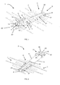
Figure 1 shows a first view in perspective of an embodiment of the immobilization device according to the invention. -
Figure 2 shows a second view in perspective of the immobilization device ofFigure 1 without the first immobilization unit. -
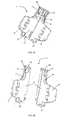
Figure 3 shows a third view in perspective of the immobilization device ofFigure 1 with the first immobilization unit inclined and without the side flaps. -
Figure 4 shows a detail according to the IV-IV line of the immobilization device ofFigure 1 without the coupling means and with the first immobilization unit not inclined. -
Figure 5 A shows a first view of the first immobilization unit ofFigure 3 . -
Figure 5B shows a second view of the first immobilization unit ofFigure 5A . -
Figure 6 shows a view of a patient immobilized in the immobilization device ofFigure 1 . - The
immobilization device 1 of the invention, as shown inFigure 1 , comprises afirst immobilization unit 2 and asecond immobilization unit 3. Thefirst immobilization unit 2 comprises abase 10, as shown inFigure 5A , on which is disposed afirst locking unit 4 to immobilize the skull-cervical anatomical area and asecond locking unit 5 to immobilize the thoracic-abdominal area of the patient. Thesecond immobilization unit 3, shown in more detail inFigure 2 , is suitable for receiving and fixing thefirst immobilization unit 2 and comprises athird locking unit 6 that immobilizes the pelvis and the patient's lower limbs. Theimmobilization device 1 also comprises a plurality of fixing means 7, which enable the patient to be kept in the immobilize position. - To optimise the immobilization of the patient, and thereby reducing the risk of causing more injuries or even aggravating the injuries already suffered, the
second locking unit 5 of thefirst immobilization unit 2 comprises two rigid orsemi-rigid flaps 9, preferably arched, to follow the patient's outline, fitted to each side of thebase 10 in a pivoting and/or detachable manner, as shown inFigures 5A and 5B . Saidflaps 9 surround and immobilize (through the use of the corresponding fixing means 7) the thorax and the abdomen of the patient, as shown inFigure 6 . As a result, the patient and thefirst immobilization unit 2 are moved together as one as if they were a single body. This is especially advantageous, for example, in the rescue of a patient with a multiple polytrauma, who is trapped inside a vehicle, whose extrication and transporting is vital so as not to aggravate the injuries suffered by the patient. - In a first embodiment of the invention, the
base 10 of thefirst immobilization unit 2 comprises two parts, as shown inFigure 5B , which are joined laterally, as shown inFigure 5 A . The two parts have substantially the same width. This feature is really advantageous, especially for immobilizing the patient in areas of reduced accessibility, such as the inside of a vehicle that has suffered an accident. Each part of thefirst immobilization unit 2 is approached from each side of the patient, joining both parts in a simple manner behind the back of the patient and being fixed by means of asafety bolt 24. This prevents having to move the patient in order to house and fix thefirst immobilization unit 2 in thesecond immobilization unit 3. In emergency situations it is difficult to assess the internal injuries suffered by the patient, which means that the patient must be moved as little as possible so as not to aggravate the injuries and even cause new ones during the immobilization. - Once the
immobilization device 2 has been placed behind the patient's back, theflaps 9 are approached, each one pivoting on its axis situated on the edge of thebase 10, in order to surround the patient's abdomen and/or thorax. The skull-cervical area of the patient is then immobilized, as will be detailed hereinafter, and the patient is then immobilized from the waist or pelvis upwards through the use of the fixing means 7. Thanks to the fact that theflaps 9 surround the patient, there is no relative movement between the patient and thefirst immobilization unit 2, so thefirst immobilization unit 2 and the patient are moved together as one as if they were a single body. This prevents the incorrect movement of the patient, thereby preventing, for example, injuries to the spinal column during the extrication and transporting of the patient. In the first embodiment, theflaps 9 and thebase 10 of thefirst immobilization unit 2 are made of the same material so that thefirst immobilization unit 2 is more robust and the patient is more protected. In addition, during the immobilization of the abdominal and thoracic area of the patient, the patient's ribs are prevented, for example, from suffering injury during the fixing or fastening of the fixing means 7 due to an excessive force exerted directly on the patient's body. However, theflaps 9 and thebase 10 may optionally be made of different material in order to find different performs of the same. - In the first embodiment of the invention, the
flaps 9 of thefirst immobilization unit 2 are pivoting and detachable. This feature is especially useful in making the rescue operation of the rescue team members easier. Theflaps 9 may be detached before starting rescue operation, and once the skull-cervical area of the patient has been immobilized, theflaps 9 may be fitted once again, by the sides of the patient, in order to immobilize the abdomen and/or the thorax areas. The rescue team members thus have greater visibility and control of the situation. - In a second embodiment, where the
base 10 of thefirst immobilization unit 2 does not comprise two parts, the solution by which theflaps 9 are detachable is very advantageous for positioning thefirst immobilization unit 2 correctly in relation to the patient without unnecessary obstacles, reducing their movements and offering greater visibility and control of the situation. - Thanks to the arched shape of the
flaps 9, these adapt to all types of bodies, including adults, children and corpulent or thin people and so on, approaching more or less to adapt to the outline of the patient. As a result, if the patient is a strong person theflaps 9 surround the patient, with a medium-sized space being left between bothflaps 9. If the patient is a thin person or a child, theflaps 9 surround the patient, with a minimal space being left between them, and if the patient is a corpulent or obese person the space between theflaps 9 is larger. - To immobilize the skull-cervical area of the patient, as shown in
Figure 5A , thefirst locking unit 4 of thefirst immobilization unit 2 comprises skull fixing means 13 in the form of pads, preferably made of plastic, which are adjustable so they can adapt to the differing sizes of patients' skulls, and detachable so that they can be easily cleaned, among other functions. Thefirst locking unit 4 also comprises cervical fixing means 14. Said means comprise a second set of adjustable and detachable pads, as shown inFigure 1 , and acervical immobilizer 15, preferably in the form of as a surgical collar, which is connected to the second set of pads by means of connection means, preferably by Velcro. As shown inFigure 5A , thecervical immobilizer 15 of the first embodiment comprises anopening 29 to enable cricoid or airway puncture should it be necessary. If the patient has already been assisted and has had the surgical collar fitted, thefirst immobilization unit 2 could do without the cervical fixing means, replacing them by the means already possessed by the patient. Trough the use of the fixing means 7 the skull-cervical area of the patient is ultimately fixed to thefirst immobilization unit 2, as shown inFigure 6 . - The
first immobilization unit 2 may comprise on one side storage means for storing auxiliary elements such as monitoring cables, so that the rescue team members always have everything they need to hand. It may also comprise auxiliary guidance means, not shown in the drawings, to guide said auxiliary elements so that they do not bother the patient. They may even guide additional elements such as an oxygen cylinder, which is needed to aid a patient suffering asphyxia. - Once the patient has been immobilized from the waist or pelvis up, the
first immobilization unit 2 is fitted on thesecond immobilization unit 3 ofFigure 2 , if thefirst immobilization unit 2 has been taken out beforehand (for example, to immobilize the patient inside the vehicle that has suffered an accident or to rescue a person in the sea). To enable this, thefirst immobilization unit 2, as shown inFigure 3 , comprises guidance means 12, preferably in the form of grooves, which cooperate with coupling means 16, preferably in the form of rods, comprised in thesecond immobilization unit 3, the patient thus being lied down in a horizontal position, as shown inFigure 6 , thus preventing the patient from having to be moved in order to transfer them to another transfer or transporting unit, such as a stretcher. The coupling means 16 of thesecond immobilization unit 3 are housed in the guidance means 12 of thefirst immobilization unit 2, and then thefirst immobilization unit 2 is moved towards the lower part of thesecond immobilization unit 3 until fixingprotuberances 27 are housed in retaining means 28. The fixingprotuberances 27 are preferably in a circular form to enable thefirst immobilization unit 2 to pivot and are comprised in the lower part of thebase 10 of thefirst immobilization unit 2. The retaining means 28 are preferably in the form of a groove and are comprised in the top part of thethird locking unit 6 of thesecond immobilization unit 3, as shown in detail inFigure 4 . Finally, thefirst immobilization unit 2 is locked, in other words it is fixed and secured, by means of locking means 17, shown inFigures 1 and 2 , comprised in thesecond immobilization unit 3. The locking means 17 are movable, so that said locking means 17 are moved towards thefirst immobilization unit 2 until retaining means 25 shown inFigure 2 , preferably in the form of a groove, fix at least in oneprotuberance 26, preferably rectangular in shape, comprised in the top part of thebase 10 of thefirst immobilization unit 2. The first embodiment of the invention comprises aprotuberance 26 in the top part of each half of thebase 10 of thefirst immobilization unit 2, as shown inFigure 3 . - As shown in
Figure 2 , thethird locking unit 6 of thesecond immobilization unit 3 comprises analigner 20, preferably in the form of a pad, which helps keep the patient's pelvis and lower limbs aligned so that they are immobilized in the correct position, through the fixing means 7. In the first embodiment, thealigner 20 is detachable to make cleaning work easier. Thealigner 20, as shown inFigure 6 , is disposed between the patient's legs. - The first embodiment of the
immobilization device 1 of the invention also comprises, in the lower part, approximately at the level of the feet, additional fixing means 8, which are mainly T-shaped, to immobilize the patient's ankles and feet, replacing the splints known in the prior art. - Thanks to the
immobilization device 1 of the invention the need to use auxiliary elements such as collars, splints, short rigid tables or long rigid tables is reduced, thereby creating more space in the ambulance and making it easier for the members of the rescue team to go about their work. - The three
locking units immobilization device 1 cooperate to keep the patient immobilized in the ideal position. - Normally the
immobilization device 1 is supported on a surface, and in order for the members of the rescue team to handle saiddevice 1, at least thefirst immobilization unit 2 comprises in its lower part a plurality ofsupport protuberances 11, as shown inFigure 3 , that enable a gap between thefirst immobilization unit 2 and the support surface, a gap sufficiently large for the members of the rescue team to put their hands in. Thesecond immobilization unit 3 may also comprise similar support protuberances. - The
immobilization device 1 is made easier to handle by the fact that it comprises gripping means that comprise a plurality ofholes 21 disposed on the perimeter, both in thefirst immobilization unit 2 and in thesecond immobilization unit 3, through which the rescue team members may put their hands. The first embodiment of the invention also comprises at least one set ofhandles 22 disposed on one of the ends of thedevice 1. Alternatively, thedevice 1 may also comprise another set ofhandles 22 on the opposite end. Said handles 22 make it easier to transport the patient as they balance the forces better. - As an alternative, in a third embodiment, the
immobilization device 1 of the invention comprises auxiliary fastening means, not shown in the figures, which may be fixed to hitching means provided, for example, in an helicopter. - As an additional alternative, in a fourth embodiment, the
second immobilization unit 3 comprises sliding means (not shown in the figures), preferably in the form of wheels. The wheels may be pulled out and/or height-adjustable, so that theimmobilization device 1 of the invention may replace the stretcher traditionally known in the prior art. - As shown in
Figure 2 , and in further detail inFigure 3 , the locking means 17 of thesecond immobilization unit 3 comprise support means 18 that cooperate with thefirst immobilization unit 2 to keep saidfirst immobilization unit 2 in an inclined position when theimmobilization unit 2 pivots according to atransverse axis 19 formed between the connection of thefirst immobilization unit 2 and thesecond immobilization unit 3, being positioned approximately at the level of the patient's hips or pelvis. This option is very useful for incorporating the patient. To achieve this, first of all thefirst immobilization unit 2 is lifted pivoting in relation to theaxis 19, and then the support means 18 are rotated upwards until aprotuberance 23 comprised in the support means 18 is housed in a housing disposed in the rear part of thebase 10 of thefirst immobilization unit 2. Thefirst immobilization unit 2 may have various housings at different levels to enable different degrees of inclination. This feature is also advantageous for transferring patients in a safe and comfortable manner to a hospital, residence, rehabilitation centre, etc. - The
immobilization device 1 of the invention is manufactured from a light, radio-transparent and floating material. As it is radio-transparent, there is no need to transfer the patient to another unit or stretcher in order to be explored by X-ray or by a magnetic resonance. In extreme cases, the patient may be operated in theatre on theimmobilization device 1. - The
immobilization device 1 of the invention avoids the unnecessary movements of the patient until having a complete and definitive diagnosis, thereby reducing the risk of causing further injury or even aggravating the injuries already suffered. - When the rescue takes place in an area where there is water, the
immobilization device 1 of the invention may also be used, as it floats. In such cases, the patient is supported on theimmobilization device 1 or only thefirst immobilization unit 2. As theflaps 9 are hinged, the patient may be immobilized while leaving the abdomen area free in the event that there is a need for the patient to undergo cardiorespiratory or cardiopulmonary resuscitation. - To make the
immobilization device 1 of the invention easier to use, it may comprise colour codes to guide the rescue team members when immobilizing the patient. For example, the fixing means 7 may thus be coloured so that the rescue team members are able to identify which fixing means 7 have to be connected to each other. In addition, thedevice 1 may optionally comprise bright colours or reflective elements to enable the rapid identification of thedevice 1. - "Rescue team members" are defined as any personnel involved in the rescue or transfer of a patient. In other words, the
immobilization device 1 of the invention is so intuitive and easy-to-use that it is suitable for use by both qualified health personnel and non-health personnel. Theimmobilization device 1 is suitable for forming part of first aid equipment and may be located in specific places that are, for example, much frequented, such as shopping centres, airports, sports centres, casinos, schools, colleges, universities, sports clubs and associations etc as well as, evidently, in ambulances and hospitals. It is also an ideal tool for use by lifeguards in swimming pools and on beaches. - The
immobilization device 1 of the invention is detachable, which means that the space required for its storage is considerably reduced. In this respect, in the first embodiment, thesecond immobilization unit 3 is detachable, so that the locking means 17, the coupling means 16 and thethird locking unit 6, along with thefirst immobilization unit 2, may be stacked for their storage. This feature also makes it easier to clean theimmobilization device 1. Alternatively, thesecond immobilization unit 3 may also be fitted together, with the result that the coupling means 16 slide along some slidingmeans 30, preferably in the form of holes, until the locking means 17 come up against thethird locking unit 6. To assemble thesecond immobilization unit 3 all that is required is to pull on the locking means 17 until the coupling means 16 reach the end of their path.
Claims (15)
- Immobilization device for immobilizing a patient, comprisinga first immobilization unit (2) that comprises a base (10) on which is disposeda first locking unit (4) to immobilize the skull-cervical anatomical area and a second locking unit (5) to immobilize the thoracic-abdominal area of the patient, anda second immobilization unit (3) suitable for receiving and fixing said first immobilization unit (2), which comprises a third locking unit (6) to immobilize the patient from the waist down,and said device (1) comprising a plurality of fixing means (7) that enable the patient to be kept in the immobilized position,
characterised in that said second locking unit (5) comprises two rigid or semi-rigid flaps (9), preferably arched, fitted on each side of the base (10) in a pivoting and/or detachable manner, said flaps (9) being suitable for surrounding and immobilizing, through the use of the corresponding fixing means (7), the patient's abdomen and/or thorax area. - Device according to claim 1, wherein the base (10) of the first immobilization unit (2) comprises two parts that are joined to each other laterally.
- Device according to claim 2, wherein the two parts of the base (10) of the first immobilization unit (2) have substantially the same width.
- Device according to any of the preceding claims, wherein the flaps (9) are made of the same material as the base (10).
- Device according to any of the preceding claims, wherein at least the first immobilization unit (2) comprises in its lower part a plurality of support protuberances (11) that enable a gap between the first immobilization unit (2) and the support surface of said unit (2) when the unit (2) is supported on said surface.
- Device according to any of the preceding claims, wherein the first immobilization unit (2) also comprises guidance means (12), preferably in the form of grooves, which cooperate with coupling means (16), preferably in the form of rods, comprised in the second immobilization unit (3).
- Device according to claim 6, wherein the second immobilization unit (3) also comprises locking means (17) to fix and secure the first immobilization unit (2) when the guidance means (12) of the first immobilization unit (2) are housed in the coupling means (16).
- Device according to claim 7, wherein the locking means (17) of the second immobilization unit (3) are movable and comprise retaining means (25), preferably in the form of a groove, that retain or fix at least one protuberance (26), preferably rectangular in shape, comprised in the top part of the base (10) of the first immobilization unit (2).
- Device according to claims 7 or 8, wherein the locking means (17) comprise support means (18) that cooperate with the first immobilization unit (2) to keep said first immobilization unit (2) in an inclined position when the immobilization unit (2) pivots according to a transverse axis (19), formed between the connection of the first and second immobilization unit (2, 3), being positioned approximately at the level of the patient's hips or pelvis.
- Device according to any of the preceding claims, wherein the first locking unit (4) of the first immobilization unit (2) comprises adjustable and detachable skull fixing means (13) that comprise a set of pads, preferably made of plastic, , and also comprises adjustable and detachable cervical fixing means (14) that comprise a second set of pads and a cervical immobilizer (15), preferably in the form of a surgical collar, which is connected to the second set of pads by means of connection means.
- Device according to any of the preceding claims, wherein the third locking unit (6) comprises an aligner (20), preferably in the form of a pad, which helps keep the patient's pelvis and lower limbs aligned so that they are immobilized in the correct position.
- Device according to any of the preceding claims, which comprises gripping means to be handled by the rescue team, which comprise a plurality of holes (21) disposed on the perimeter and/or at least a set of handles (22), disposed at least on one of the ends of said device (1).
- Device according to any of the preceding claims, which comprises, in the lower part, approximately at the level of the patient's feet, additional fixing means (8), preferably T-shaped, to immobilize the feet and/or ankles of the patient.
- Device according to any of the preceding claims, wherein the second immobilization unit (3) is detachable and/or may be fitted together.
- Device according to any of the preceding claims, wherein said device is manufactured from a light, radio-transparent and floating material.
Priority Applications (3)
| Application Number | Priority Date | Filing Date | Title |
|---|---|---|---|
| EP11382298A EP2572692A1 (en) | 2011-09-20 | 2011-09-20 | Immobilization device for immobilizing a patient |
| PCT/EP2012/068275 WO2013041495A1 (en) | 2011-09-20 | 2012-09-17 | Immobilization device for immobilizing a patient |
| ARP120103475 AR087982A1 (en) | 2011-09-20 | 2012-09-20 | FIXED DEVICE FOR IMMOBILIZING A PATIENT |
Applications Claiming Priority (1)
| Application Number | Priority Date | Filing Date | Title |
|---|---|---|---|
| EP11382298A EP2572692A1 (en) | 2011-09-20 | 2011-09-20 | Immobilization device for immobilizing a patient |
Publications (1)
| Publication Number | Publication Date |
|---|---|
| EP2572692A1 true EP2572692A1 (en) | 2013-03-27 |
Family
ID=46875811
Family Applications (1)
| Application Number | Title | Priority Date | Filing Date |
|---|---|---|---|
| EP11382298A Withdrawn EP2572692A1 (en) | 2011-09-20 | 2011-09-20 | Immobilization device for immobilizing a patient |
Country Status (3)
| Country | Link |
|---|---|
| EP (1) | EP2572692A1 (en) |
| AR (1) | AR087982A1 (en) |
| WO (1) | WO2013041495A1 (en) |
Cited By (2)
| Publication number | Priority date | Publication date | Assignee | Title |
|---|---|---|---|---|
| IT201600073244A1 (en) * | 2016-07-13 | 2018-01-13 | Vezzani Spa | Stretcher for transferring people |
| CN114145934A (en) * | 2021-11-27 | 2022-03-08 | 岳阳职业技术学院 | Modular easily-assembled diagnosis and treatment bed and assembly assembling equipment thereof |
Citations (6)
| Publication number | Priority date | Publication date | Assignee | Title |
|---|---|---|---|---|
| FR2583977A1 (en) * | 1985-06-28 | 1987-01-02 | Thomson Csf | Stretcher intended in particular for people with injuries to the vertebral column |
| DE3546526A1 (en) | 1985-07-06 | 1987-04-23 | Stollenwerk Fabrik Fuer Sanita | Stretcher |
| US5154186A (en) * | 1990-04-12 | 1992-10-13 | Laurin Frederick J | Spinal restraint |
| US5496092A (en) * | 1992-05-06 | 1996-03-05 | Gary R. Williams | Multi-position pediatric immobilizer and transport device |
| EP1214919A1 (en) * | 2000-12-14 | 2002-06-19 | Her Majesty the Queen as represented by the Minister of National Defence | Field-deployable stretcher with forced air warming system |
| US7082632B2 (en) | 2002-12-18 | 2006-08-01 | Hood Thomas W | Collapsible, extendable, traction-providing, portable rescue device |
-
2011
- 2011-09-20 EP EP11382298A patent/EP2572692A1/en not_active Withdrawn
-
2012
- 2012-09-17 WO PCT/EP2012/068275 patent/WO2013041495A1/en active Application Filing
- 2012-09-20 AR ARP120103475 patent/AR087982A1/en not_active Application Discontinuation
Patent Citations (6)
| Publication number | Priority date | Publication date | Assignee | Title |
|---|---|---|---|---|
| FR2583977A1 (en) * | 1985-06-28 | 1987-01-02 | Thomson Csf | Stretcher intended in particular for people with injuries to the vertebral column |
| DE3546526A1 (en) | 1985-07-06 | 1987-04-23 | Stollenwerk Fabrik Fuer Sanita | Stretcher |
| US5154186A (en) * | 1990-04-12 | 1992-10-13 | Laurin Frederick J | Spinal restraint |
| US5496092A (en) * | 1992-05-06 | 1996-03-05 | Gary R. Williams | Multi-position pediatric immobilizer and transport device |
| EP1214919A1 (en) * | 2000-12-14 | 2002-06-19 | Her Majesty the Queen as represented by the Minister of National Defence | Field-deployable stretcher with forced air warming system |
| US7082632B2 (en) | 2002-12-18 | 2006-08-01 | Hood Thomas W | Collapsible, extendable, traction-providing, portable rescue device |
Cited By (2)
| Publication number | Priority date | Publication date | Assignee | Title |
|---|---|---|---|---|
| IT201600073244A1 (en) * | 2016-07-13 | 2018-01-13 | Vezzani Spa | Stretcher for transferring people |
| CN114145934A (en) * | 2021-11-27 | 2022-03-08 | 岳阳职业技术学院 | Modular easily-assembled diagnosis and treatment bed and assembly assembling equipment thereof |
Also Published As
| Publication number | Publication date |
|---|---|
| AR087982A1 (en) | 2014-04-30 |
| WO2013041495A1 (en) | 2013-03-28 |
Similar Documents
| Publication | Publication Date | Title |
|---|---|---|
| US5476432A (en) | Medical stroller | |
| US5397171A (en) | Gait assistance harness apparatus | |
| US5027833A (en) | Extrication and spinal restraint device | |
| US9351901B1 (en) | Gait training tool | |
| US5263495A (en) | Moving harness and method of use | |
| US11246779B2 (en) | Manual assistance transfer belt utilizing individual thigh straps | |
| WO2001080802A2 (en) | Method and apparatus for assisting a child to walk | |
| US8663136B1 (en) | Wheeled support assembly for the disabled | |
| US20180133094A1 (en) | Medical transporter | |
| US20150021118A1 (en) | Assistant Harness | |
| US5253657A (en) | Harness utilized in shifting a position of a human wearer | |
| JP2007082798A (en) | Posture supporting tool for handicapped person | |
| EP2572692A1 (en) | Immobilization device for immobilizing a patient | |
| JP2008161661A (en) | Diaper type care belt | |
| US9925097B2 (en) | Portable stretcher | |
| KR102132597B1 (en) | A body straighter | |
| EP3377017B1 (en) | Device for transport and medical care of patients | |
| US20180333287A1 (en) | Specific immobilisation device | |
| Gawlowski et al. | Victim evacuation techniques in emergency conditions | |
| RU64508U1 (en) | STORERS "RESCUE OF EMERCOM-1" | |
| ES2909106T3 (en) | Stretcher | |
| WO2014033721A1 (en) | Portable stretcher | |
| EP3195840B1 (en) | Device for immobilising injured children in a chair for transporting said children in vehicles by road, and instructions for use | |
| ES2491416B1 (en) | Pediatric immobilizer device for trauma care and ambulance transfers | |
| JP3130448U (en) | Diaper-type assistance belt |
Legal Events
| Date | Code | Title | Description |
|---|---|---|---|
| PUAI | Public reference made under article 153(3) epc to a published international application that has entered the european phase |
Free format text: ORIGINAL CODE: 0009012 |
|
| AK | Designated contracting states |
Kind code of ref document: A1 Designated state(s): AL AT BE BG CH CY CZ DE DK EE ES FI FR GB GR HR HU IE IS IT LI LT LU LV MC MK MT NL NO PL PT RO RS SE SI SK SM TR |
|
| AX | Request for extension of the european patent |
Extension state: BA ME |
|
| 17P | Request for examination filed |
Effective date: 20130927 |
|
| RBV | Designated contracting states (corrected) |
Designated state(s): AL AT BE BG CH CY CZ DE DK EE ES FI FR GB GR HR HU IE IS IT LI LT LU LV MC MK MT NL NO PL PT RO RS SE SI SK SM TR |
|
| RIC1 | Information provided on ipc code assigned before grant |
Ipc: A61G 1/04 20060101AFI20131218BHEP Ipc: A61G 1/044 20060101ALI20131218BHEP Ipc: A61G 1/013 20060101ALN20131218BHEP Ipc: A61G 1/048 20060101ALN20131218BHEP |
|
| GRAP | Despatch of communication of intention to grant a patent |
Free format text: ORIGINAL CODE: EPIDOSNIGR1 |
|
| INTG | Intention to grant announced |
Effective date: 20140127 |
|
| GRAP | Despatch of communication of intention to grant a patent |
Free format text: ORIGINAL CODE: EPIDOSNIGR1 |
|
| INTG | Intention to grant announced |
Effective date: 20140521 |
|
| RIC1 | Information provided on ipc code assigned before grant |
Ipc: A61G 1/044 20060101ALI20140512BHEP Ipc: A61G 1/048 20060101ALN20140512BHEP Ipc: A61G 1/04 20060101AFI20140512BHEP Ipc: A61G 1/013 20060101ALN20140512BHEP |
|
| STAA | Information on the status of an ep patent application or granted ep patent |
Free format text: STATUS: THE APPLICATION IS DEEMED TO BE WITHDRAWN |
|
| 18D | Application deemed to be withdrawn |
Effective date: 20141001 |