EP2572681A1 - Implant and method for manufacturing the same - Google Patents
Implant and method for manufacturing the same Download PDFInfo
- Publication number
- EP2572681A1 EP2572681A1 EP12180765A EP12180765A EP2572681A1 EP 2572681 A1 EP2572681 A1 EP 2572681A1 EP 12180765 A EP12180765 A EP 12180765A EP 12180765 A EP12180765 A EP 12180765A EP 2572681 A1 EP2572681 A1 EP 2572681A1
- Authority
- EP
- European Patent Office
- Prior art keywords
- baseline
- elements
- order
- imaginary
- web
- Prior art date
- Legal status (The legal status is an assumption and is not a legal conclusion. Google has not performed a legal analysis and makes no representation as to the accuracy of the status listed.)
- Withdrawn
Links
Images


Classifications
-
- A—HUMAN NECESSITIES
- A61—MEDICAL OR VETERINARY SCIENCE; HYGIENE
- A61F—FILTERS IMPLANTABLE INTO BLOOD VESSELS; PROSTHESES; DEVICES PROVIDING PATENCY TO, OR PREVENTING COLLAPSING OF, TUBULAR STRUCTURES OF THE BODY, e.g. STENTS; ORTHOPAEDIC, NURSING OR CONTRACEPTIVE DEVICES; FOMENTATION; TREATMENT OR PROTECTION OF EYES OR EARS; BANDAGES, DRESSINGS OR ABSORBENT PADS; FIRST-AID KITS
- A61F2/00—Filters implantable into blood vessels; Prostheses, i.e. artificial substitutes or replacements for parts of the body; Appliances for connecting them with the body; Devices providing patency to, or preventing collapsing of, tubular structures of the body, e.g. stents
- A61F2/82—Devices providing patency to, or preventing collapsing of, tubular structures of the body, e.g. stents
- A61F2/86—Stents in a form characterised by the wire-like elements; Stents in the form characterised by a net-like or mesh-like structure
- A61F2/90—Stents in a form characterised by the wire-like elements; Stents in the form characterised by a net-like or mesh-like structure characterised by a net-like or mesh-like structure
- A61F2/91—Stents in a form characterised by the wire-like elements; Stents in the form characterised by a net-like or mesh-like structure characterised by a net-like or mesh-like structure made from perforated sheet material or tubes, e.g. perforated by laser cuts or etched holes
- A61F2/915—Stents in a form characterised by the wire-like elements; Stents in the form characterised by a net-like or mesh-like structure characterised by a net-like or mesh-like structure made from perforated sheet material or tubes, e.g. perforated by laser cuts or etched holes with bands having a meander structure, adjacent bands being connected to each other
- A61F2002/91508—Stents in a form characterised by the wire-like elements; Stents in the form characterised by a net-like or mesh-like structure characterised by a net-like or mesh-like structure made from perforated sheet material or tubes, e.g. perforated by laser cuts or etched holes with bands having a meander structure, adjacent bands being connected to each other the meander having a difference in amplitude along the band
-
- A—HUMAN NECESSITIES
- A61—MEDICAL OR VETERINARY SCIENCE; HYGIENE
- A61F—FILTERS IMPLANTABLE INTO BLOOD VESSELS; PROSTHESES; DEVICES PROVIDING PATENCY TO, OR PREVENTING COLLAPSING OF, TUBULAR STRUCTURES OF THE BODY, e.g. STENTS; ORTHOPAEDIC, NURSING OR CONTRACEPTIVE DEVICES; FOMENTATION; TREATMENT OR PROTECTION OF EYES OR EARS; BANDAGES, DRESSINGS OR ABSORBENT PADS; FIRST-AID KITS
- A61F2/00—Filters implantable into blood vessels; Prostheses, i.e. artificial substitutes or replacements for parts of the body; Appliances for connecting them with the body; Devices providing patency to, or preventing collapsing of, tubular structures of the body, e.g. stents
- A61F2/82—Devices providing patency to, or preventing collapsing of, tubular structures of the body, e.g. stents
- A61F2/86—Stents in a form characterised by the wire-like elements; Stents in the form characterised by a net-like or mesh-like structure
- A61F2/90—Stents in a form characterised by the wire-like elements; Stents in the form characterised by a net-like or mesh-like structure characterised by a net-like or mesh-like structure
- A61F2/91—Stents in a form characterised by the wire-like elements; Stents in the form characterised by a net-like or mesh-like structure characterised by a net-like or mesh-like structure made from perforated sheet material or tubes, e.g. perforated by laser cuts or etched holes
- A61F2/915—Stents in a form characterised by the wire-like elements; Stents in the form characterised by a net-like or mesh-like structure characterised by a net-like or mesh-like structure made from perforated sheet material or tubes, e.g. perforated by laser cuts or etched holes with bands having a meander structure, adjacent bands being connected to each other
- A61F2002/91525—Stents in a form characterised by the wire-like elements; Stents in the form characterised by a net-like or mesh-like structure characterised by a net-like or mesh-like structure made from perforated sheet material or tubes, e.g. perforated by laser cuts or etched holes with bands having a meander structure, adjacent bands being connected to each other within the whole structure different bands showing different meander characteristics, e.g. frequency or amplitude
-
- A—HUMAN NECESSITIES
- A61—MEDICAL OR VETERINARY SCIENCE; HYGIENE
- A61F—FILTERS IMPLANTABLE INTO BLOOD VESSELS; PROSTHESES; DEVICES PROVIDING PATENCY TO, OR PREVENTING COLLAPSING OF, TUBULAR STRUCTURES OF THE BODY, e.g. STENTS; ORTHOPAEDIC, NURSING OR CONTRACEPTIVE DEVICES; FOMENTATION; TREATMENT OR PROTECTION OF EYES OR EARS; BANDAGES, DRESSINGS OR ABSORBENT PADS; FIRST-AID KITS
- A61F2/00—Filters implantable into blood vessels; Prostheses, i.e. artificial substitutes or replacements for parts of the body; Appliances for connecting them with the body; Devices providing patency to, or preventing collapsing of, tubular structures of the body, e.g. stents
- A61F2/82—Devices providing patency to, or preventing collapsing of, tubular structures of the body, e.g. stents
- A61F2/86—Stents in a form characterised by the wire-like elements; Stents in the form characterised by a net-like or mesh-like structure
- A61F2/90—Stents in a form characterised by the wire-like elements; Stents in the form characterised by a net-like or mesh-like structure characterised by a net-like or mesh-like structure
- A61F2/91—Stents in a form characterised by the wire-like elements; Stents in the form characterised by a net-like or mesh-like structure characterised by a net-like or mesh-like structure made from perforated sheet material or tubes, e.g. perforated by laser cuts or etched holes
- A61F2/915—Stents in a form characterised by the wire-like elements; Stents in the form characterised by a net-like or mesh-like structure characterised by a net-like or mesh-like structure made from perforated sheet material or tubes, e.g. perforated by laser cuts or etched holes with bands having a meander structure, adjacent bands being connected to each other
- A61F2002/9155—Adjacent bands being connected to each other
- A61F2002/91575—Adjacent bands being connected to each other connected peak to trough
-
- A—HUMAN NECESSITIES
- A61—MEDICAL OR VETERINARY SCIENCE; HYGIENE
- A61F—FILTERS IMPLANTABLE INTO BLOOD VESSELS; PROSTHESES; DEVICES PROVIDING PATENCY TO, OR PREVENTING COLLAPSING OF, TUBULAR STRUCTURES OF THE BODY, e.g. STENTS; ORTHOPAEDIC, NURSING OR CONTRACEPTIVE DEVICES; FOMENTATION; TREATMENT OR PROTECTION OF EYES OR EARS; BANDAGES, DRESSINGS OR ABSORBENT PADS; FIRST-AID KITS
- A61F2230/00—Geometry of prostheses classified in groups A61F2/00 - A61F2/26 or A61F2/82 or A61F9/00 or A61F11/00 or subgroups thereof
- A61F2230/0002—Two-dimensional shapes, e.g. cross-sections
- A61F2230/0004—Rounded shapes, e.g. with rounded corners
- A61F2230/0013—Horseshoe-shaped, e.g. crescent-shaped, C-shaped, U-shaped
Definitions
- the present invention relates to an implant, in particular an intraluminal endoprosthesis, with a perforated, preferably hollow-cylindrical basic structure which has at least one section, wherein at least one web is arranged in each section.
- implants are endovascular prostheses or other endoprostheses, for example stents (vascular stents (vascular stent, including the heart and heart valve stent, eg mitral stent, pulmonary valve stent), bile duct stents), endoprostheses for occluding persistent foramen ovals (PFO), Stent Grafts for the treatment of aneurysms, endoprostheses for closing an ASD (atrial septal defect) and prostheses in the area of hard and soft tissue.
- stents vascular stents (vascular stent, including the heart and heart valve stent, eg mitral stent, pulmonary valve stent), bile duct stents)
- endoprostheses for occluding persistent foramen ovals (PFO)
- Stent Grafts for the treatment of aneurysms
- endoprostheses for closing an ASD atrial sept
- implants are used more frequently as stents, which are used for the treatment of stenoses (vessel narrowing). They have a perforated tubular or hollow cylindrical basic structure which is open at both longitudinal ends.
- the basic structure of conventional stents is often composed of individual stitches which are formed from differently shaped webs (struts), for example zigzag or meander-shaped webs.
- Such an implant is often inserted by means of a catheter in the vessel to be treated and serves to support the vessel over a longer period of time (months to years).
- stents narrowed areas in the vessels can be widened, resulting in a lumen gain.
- the aim is to achieve through the implant a large and homogeneous coverage of the vessel wall. Further, migration of a stent in vivo (e.g., in the artery) is to be prevented and the strength of stents increased under the loading of the corresponding vessel.
- the radiopacity of the implants could be improved to allow easy monitoring of the placement of the implants and their behavior in vivo from time to time; the currently available thin struts of stents often have low radiopacity.
- the object of the present invention is therefore to provide an implant having the above-mentioned improvements.
- the at least one land of a portion of an implant according to the invention comprises a plurality of like, simple and interconnected elements whose basic shape is substantially similar to the shape of baseline elements of at least one imaginary first order baseline also extending in the section the at least one imaginary first-order baseline represents a reference line for the arrangement of the elements and the elements are at most half the size of the baseline elements.
- the last indicated feature means that the elements in at least one dimension, preferably in the dimension along the baseline element, have a dimension at most half as large as the baseline elements. This means that in the case that the dimension of the element along the baseline element is referred to as the length of the element, the elements have at most half the length of the baseline elements.
- the height of the elements can vary and is preferably also half the height of the baseline elements.
- the at least one web of the implant which is arranged in a section, is formed from a plurality of elements.
- These elements have the same basic shape, which is substantially similar to the shape of the so-called baseline elements, from which an imaginary baseline is composed.
- the baseline element is used in the respective section to form a reference line for the elements of the at least one web. Since the basic shape of the web elements and the shape of the baseline elements arranged along the baseline are substantially similar to one another, the structure of the implant according to the invention effectively produces a fractal (self-similar) structure.
- the (small) elements form a bridge that appears slender in its structure.
- the basic shape in the context of the elements of the webs, in addition to the use of simple shapes, it should also be clarified that the web width or web thickness is disregarded for the consideration of the shape of the web element and for comparison with the shape of the baseline element is left.
- the basic shape is considered to be the shape of a center line through the element or an upper or outer boundary line or a lower or inner boundary line along the element.
- a e.g. rhombus-shaped element of a ridge considered only the (mathematical two-dimensional) shape of the rhombus with respect to the corresponding baseline element and neglected the width and thickness of the sides of the rhombus.
- Preferred basic forms are the wave arc, which is preferably formed as a sine arc, the rhombus and the zig-zag element.
- substantially similar not only means the strict mathematical-geometric similarity, but also includes the cases in which the shape of the web elements and the shape of the baseline elements have the same basic shape (wave, triangle, rhombus, sine, etc.) , but in individual dimensions, radii of curvature or angles differ from each other compared to the strict mathematical-geometric similarity.
- both the baseline elements and the web elements may be designed as rhombuses, wherein the corresponding angles of the baseline diamond and the ridge diamond elements are not identical as in the strict mathematical-geometric similarity, but somewhat different.
- Preferred radii of curvature for a wave-shaped element of a web are between 0.035 mm and 1 mm.
- the length of an element of a web (along the respective base element) is preferably between 0.1 mm and 5 mm.
- the angle between two sides of a rhombus element or a zig-zag element can be in the range between 0.5 ° and 175 °.
- the design of the implant according to the invention has a decisive influence on its mechanical properties.
- the design can be varied in many ways and thus different advantageous properties of the implant can be combined.
- a higher, more homogeneous coverage of the wall of the treated body cavity can be achieved.
- This is particularly advantageous for use as an implant with a delivery of drugs.
- a good "gearing" with the wall of the treated body cavity can be achieved, so that a migration of the implant is prevented in the body cavity. Due to the small-limbed structure of the at least one web, this allows a movement in different directions, so that a higher flexibility of the implant can be achieved.
- the mechanical stresses and strains acting on the implant in the treated body cavity are better distributed than in conventional design.
- a cost advantage, in particular for braided stents (braided stents) results from the fact that the at least one web is formed from each of the same elements.
- the at least one portion of the implant is annular or helical.
- annular sections it is usually necessary, the webs of the adjacent sections with each other by means of connecting webs connect to.
- a helical design of the implant section it may be necessary to connect the webs of the superposed regions of the helix to one another by means of connecting webs.
- the at least one web of a portion or a portion of the portion is connected to the at least one web of the adjacent portion or an adjacent portion of the portion by means of at least one connecting web, which is preferably S-shaped.
- the connecting webs are connected there to the respective web, where the curvature of the respective web has a local extremum (minimum or maximum).
- a connecting web in the region of the center (with regard to the length of the web) between two adjacent connecting regions may be arranged to adjacent connecting webs along the web.
- Such tie bars are referred to as center-to-center connectors.
- Particularly suitable simple and easily produced elements or baseline elements for an implant according to the invention have the shape of a waveform arc, preferably a sinusoidal arc, a rhombus, a triangle, a zig-zag element or the like.
- the imaginary first-order baseline forms a reference line for the arrangement of the elements of the at least one land such that the elements in the section are arranged along the at least one imaginary first-order baseline.
- the elements are arranged along at least one imaginary second-order baseline, the imaginary second-order baseline being provided having the baseline elements arranged at a maximum size of 50% along the at least one first order baseline.
- the elements of the at least one web only have at most 25% of the size of the baseline elements that the at least one imaginary baseline first order (at least for the dimension along the baseline, the dimension perpendicular to the baseline may vary).
- the elements of the at least one ridge are arranged along at least one imaginary third order baseline, initially providing at least a second order baseline having the baseline elements arranged at a maximum size of 50% along the first order baseline, and further provided is at least one third order baseline having baseline elements arranged at a maximum size of 25% along the second order baseline.
- the elements of the at least one land have at most 12.5% of the size of the baseline elements of the first order baseline (all dimensions at least for the dimension along the baseline, the dimension normal to the baseline may vary).
- the last-mentioned variant of the arrangement of the elements results in a particularly delicate structure of the implant, through which a very homogeneous coverage of the wall of the respectively treated body cavity is achieved.
- Further variability in the design of the implant can be achieved by arranging the elements or baseline elements along the at least one first order baseline or at least one second order baseline, or at least one third order baseline, etc. such that the respective baseline one Represents a central line or an upper or left boundary line or a lower or right boundary line.
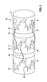
- Fig. 1 shows three sections 12 of a first embodiment of an implant according to the invention, which is designed as a stent 10.
- Each annular portion 12 has in each case a web 14, which along an imaginary, wavy baseline 17 (dashed line), wavy meandering.
- the baseline 17 is sinusoidal.
- Both the baseline 17 and the web 14 are wavy in such a way that they have mountains and valleys alternately or in each case radii of curvature that are alternately oriented proximally and distally.
- the web 14 is composed of wave-shaped elements, which are arranged along the imaginary baseline 17, that the baseline 17 forms an imaginary center line.
- the baseline 17 is also composed of individual wave arcs, preferably sine arcs, as baseline elements. Each wave arc of the web 14 is connected to the next wave arc of the web 14. Also, the wave-shaped baseline elements of the baseline 17 are interconnected.
- the length of a corrugated or S-shaped stanchion is about one-sixth the length of a wavy or S-shaped baseline element.
- the length in the baseline element is the extension in a direction perpendicular to the longitudinal direction of the stent, and in the web element the extension along the baseline element.
- connecting webs 18 are arranged, which in each case connect the web of a first section 12 to the web 14 of an adjacent section 12.
- the extending substantially in the longitudinal direction of the stent connecting webs 18 serve to absorb the forces acting on the stent in the longitudinal direction (the direction of the longitudinal axis).
- Each connecting web 18 preferably forms a wave arc, each having a mountain and a valley or extending the radii of curvature alternately opposite in a direction perpendicular to the longitudinal direction of the stent.
- Different types of connecting webs 18 may be used on the same stent, e.g.
- connecting webs 18 with different radii of curvature e.g. a first type of connecting webs 18 between the first portion 12 with a web 14 and the second portion 12 with a web 14, a second type of connecting webs 18 between the second portion 12 and a third portion 12 with a web 14 and a first type of Connecting webs 18 between the third portion 12 and a fourth portion 12 with a web 14, etc.
- the stent can be produced as a so-called slotted-tube stent. This means that the cavities between the individual webs are cut out by means of a laser from the starting material, a tube.
- the stent can be manufactured as a so-called braided stent. The stent is braided out of wire.
- other types of preparation are conceivable, e.g. the welding of individual parts of the stent or rapid prototyping.
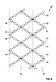
- FIG. 2 the development of a second embodiment of a stent is shown.
- Each annular portion 22 has webs 24 which form rhombic stitches along imaginary baselines 27 (dashed lines). In the illustration, the annular portions 22 are delimited from each other by a dash-dot line.
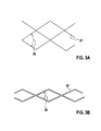
- Fig. 3 illustrates the arrangement of the imaginary first order basal lines 27 during Fig. 3b ) shows the webs 24 in an enlarged view.
- the imaginary baselines 27 form a center line through the rhombic elements of the webs 24.
- the second embodiment represents a variant in which the baseline elements (rhombs) are not in the strict mathematical-geometric sense similar to the rhombs of the webs 24. This is because the pointed inner angle 26 of the diamonds of the webs 24 is smaller than the pointed inner angle 29 of the diamonds that form the imaginary baselines 27.
- the second embodiment is therefore referred to as a fractal-like structure.
- the length of the diamonds of the webs 24 is about one-sixth of the length of the rhombs forming the baseline.
- the length in the baseline element is the extension in the longitudinal direction of the stent and in the web element the extent along the respective side of the baseline element.
- a third embodiment is shown, in which the rhombs of the webs 34 in the mathematical sense are similar to the rhombuses from which the imaginary baseline 37 composed.
- the similarity of the rhombuses is determined by the fact that the acute inner angle 36 of the web elements is the same size as the pointed inner angle 39 of the rhombs of the baseline 37.
- An implant with the webs 34, which analogous to Fig. 2 are arranged along the imaginary baselines 37, thus forming a fractal structure.
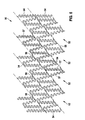
- Fig. 5 shows a fourth embodiment in which 40 webs 44 are arranged in each annular portion 42 of the stent, which are composed of juxtaposed zig-zag elements, each element contains two adjacent sides of a triangle.
- the zig-zag elements of the respective web 44 are along a Dashed line, imaginary baseline 47 is arranged, which extends in the entire section 42 on the right side of the zig-zag elements of the web 44.
- Each imaginary baseline 47 also consists of juxtaposed zig-zag elements.
- S-shaped connecting webs 48 are provided, each connecting a web 44 of a first section 42 to a web 44 of an adjacent section 42 and extending substantially in the longitudinal direction.
- the length of a zig-zag shaped stake is about one-sixth the length of a zig-zag baseline.
- the length in the baseline element is the extension in a direction perpendicular to the longitudinal direction of the stent, and in the web element the extension along the baseline element.
- FIGS. 6 and 7 illustrated fifth embodiment has webs 54, which along an imaginary baseline 57 arranged side by side wave-shaped elements provides.
- the imaginary (dashed line) baseline is also composed of wavy baseline elements that are arranged side by side together.
- the elements of the web 54 are merely substantially similar to the shape of the elements of the baseline 57.
- the baseline 57 essentially forms a center line for the arrangement of the elements of the web 54.
- the webs 54 of adjacent helical sections 52 are connected to each other via short, substantially longitudinal connecting webs 58.
- the length of a wavy-shaped Stegelements of the in the basis of Fig. 6 and 7 illustrated embodiment is approximately one-twelfth of the length of a wave-shaped baseline element.
- the length in the baseline element is the extent in a direction oblique to the longitudinal direction of the stent (see dotted lines) and in the web element the extension approximately along the baseline element.
- FIGS. 8 and 9 shown sixth and seventh embodiments contain more fractal planes.
- an imaginary second-order baseline 67 ' was formed starting from a first-order base line 67 composed of juxtaposed zig-zag elements, which is likewise composed of the zigzag elements, but only 50% of the size of the zig Have first-order baseline 67 elements.
- the likewise zig-zag-shaped elements of the web 64 are now arranged. These have only a size of about 25% compared to the zigzag elements of the first-order baseline 67.
- the zigzag elements of the first order baseline 67 are similar to the zigzag elements of the imaginary second order baseline 67 'and to the zigzag elements of the ridge 64.
- the length of a zig-zag shaped stanchion is about one fourth the length of a zig-zag of the first order baseline 67.
- the length in the baseline element of the first order baseline 67 is the extent in a direction perpendicular to the longitudinal direction of the stent and in the ridge member, the extent along the baseline element of the second order baseline 67 '.
- the length of a zig-zag of the second order baseline 67 ' is approximately half the length of a zig-zag of the first order baseline 67.
- the length of the element of the second order baseline 67' is the extent along the respective element of the first-order baseline 67.
- a further fractal plane is added. From an imaginary first-order baseline 77, an imaginary second-order baseline 77 'analogous to the procedure of in Fig. 8 formed embodiment. Similarly, an imaginary third-order baseline 77 "is formed from the second-order baseline 77 ', with the third-order baseline elements 77" being similar to the first-order baseline zigzag elements 77 and the elements of the ridge 74 imaginary third-order base line 77 "serves as a baseline for the arrangement (Side by side) of the zigzag-shaped elements of the web 74. The zig-zag elements of the webs 74 have a size of about 12.5% compared to the size of the elements of the imaginary first-order line 77. Each ridge 74 is disposed in an annular portion 72 of the implant 70.
- the length of a zigzag-shaped element of the ridge 74 is about one-eighth the length of a zig-zag of the first-order base line 77.
- the length in the baseline element of the first-order base line 77 is the extension in a direction perpendicular to the longitudinal direction.
- the length of a second-order baseline zig-zag element 77 ' is approximately one-half the length of a first-order baseline zig-zag shaped element 77 and the length of a zig-zag-shaped element of the third-order baseline 77 "is approximately one quarter of the length of a zig-zag-shaped element of the first-order baseline 77.
- the length is the extension in the element of the second-order baseline 77 ' along the respective element of the first-order baseline 77 and third in the element of the baseline Order 77 "the extent along the respective element of the second-order baseline 77 '.
- the webs 74 of adjacent sections 72 are connected together by means of S-shaped connecting webs 78 in the longitudinal direction.
- the in Fig. 8 shown sixth embodiment connecting webs 68, which connect the webs 64 of adjacent portions 62 in the longitudinal direction.
Abstract
Description
Die vorliegende Erfindung betrifft ein Implantat, insbesondere eine intraluminale Endoprothese, mit einer durchbrochenen, vorzugsweise hohlzylinderförmigen Grundstruktur, welche mindestens einen Abschnitt aufweist, wobei in jedem Abschnitt mindestens ein Steg angeordnet ist.The present invention relates to an implant, in particular an intraluminal endoprosthesis, with a perforated, preferably hollow-cylindrical basic structure which has at least one section, wherein at least one web is arranged in each section.
Medizinische Endoprothesen oder Implantate für die unterschiedlichsten Anwendungen sind in großer Vielfalt aus dem Stand der Technik bekannt. Als Implantate im Sinne der vorliegenden Erfindung sind endovaskuläre Prothesen oder sonstige Endoprothesen, beispielsweise Stents (Gefäß-Stents (vaskulärer Stent, einschließlich des Herzens und Herzklappenstents, z.B. Mitral-Stent, Pulmonalklappenstent), Gallengang-Stents), Endoprothesen zum Verschließen von persitierenden Foramen ovale (PFO), Stent Grafts zur Behandlung von Aneurysmen, Endoprothesen zum Verschließen eines ASD (Vorhofscheidewanddefekt, atrial septal defect) sowie Prothesen im Bereich des Hart- und Weichgewebes zu verstehen.Medical endoprostheses or implants for a wide variety of applications are known in great variety from the prior art. For the purposes of the present invention, implants are endovascular prostheses or other endoprostheses, for example stents (vascular stents (vascular stent, including the heart and heart valve stent, eg mitral stent, pulmonary valve stent), bile duct stents), endoprostheses for occluding persistent foramen ovals (PFO), Stent Grafts for the treatment of aneurysms, endoprostheses for closing an ASD (atrial septal defect) and prostheses in the area of hard and soft tissue.
Heutzutage werden als Implantate besonders häufig Stents eingesetzt, die zur Behandlung von Stenosen (Gefäßverengungen) dienen. Sie weisen eine durchbrochene rohrförmige oder hohlzylinderförmige Grundstruktur auf, die an beiden Längsenden offen ist. Die Grundstruktur von herkömmlichen Stents setzt sich dabei häufig aus einzelnen Maschen zusammen, welche aus verschieden geformten Stegen (Struts), beispielsweise zick-zack- oder mäander-förmigen Stegen, gebildet werden. Ein derartiges Implantat wird häufig mittels eines Katheters in das zu behandelnde Gefäß eingesetzt und dient dazu, das Gefäß über einen längeren Zeitraum (Monate bis Jahre) zu stützen. Durch den Einsatz von Stents können verengte Bereiche in den Gefäßen erweitert werden, so dass ein Lumengewinn resultiert.Nowadays implants are used more frequently as stents, which are used for the treatment of stenoses (vessel narrowing). They have a perforated tubular or hollow cylindrical basic structure which is open at both longitudinal ends. The basic structure of conventional stents is often composed of individual stitches which are formed from differently shaped webs (struts), for example zigzag or meander-shaped webs. Such an implant is often inserted by means of a catheter in the vessel to be treated and serves to support the vessel over a longer period of time (months to years). By using stents narrowed areas in the vessels can be widened, resulting in a lumen gain.
Für die Freigabe von Medikamenten aus derartigen Implantaten (zum Beispiel bei einem so genannten Drug Eluting Stent (DES)) in die Wand eines behandelten Gefäßes wird angestrebt, durch das Implantat eine große und möglichst homogene Abdeckung der Gefäßwand zu erreichen. Ferner soll ein Wandern eines Stents in vivo (z.B. in der Arterie) verhindert und die Festigkeit von Stents unter der Belastung des entsprechenden Gefäßes erhöht werden. Außerdem könnte die Röntgensichtbarkeit der Implantate verbessert werden, um die Platzierung der Implantate und ihr Verhalten in vivo von Zeit zu Zeit einfach überwachen zu können; die derzeit erhältlichen dünnen Streben von Stents verfügen häufig über eine nur geringe Röntgensichtbarkeit.For the release of drugs from such implants (for example in a so-called drug-eluting stent (DES)) in the wall of a treated vessel, the aim is to achieve through the implant a large and homogeneous coverage of the vessel wall. Further, migration of a stent in vivo (e.g., in the artery) is to be prevented and the strength of stents increased under the loading of the corresponding vessel. In addition, the radiopacity of the implants could be improved to allow easy monitoring of the placement of the implants and their behavior in vivo from time to time; the currently available thin struts of stents often have low radiopacity.
Die Aufgabe der vorliegenden Erfindung besteht somit darin, ein Implantat zu schaffen, das die oben angegebenen Verbesserungen aufweist.The object of the present invention is therefore to provide an implant having the above-mentioned improvements.
Die obige Aufgabe wird durch ein Implantat mit den Merkmalen des Anspruchs 1 gelöst.The above object is achieved by an implant having the features of
Der mindestens eine Steg eines Abschnitts eines erfindungsgemäßen Implantats weist insbesondere eine Vielzahl von gleichen, einfachen und miteinander verbundenen Elementen auf, deren Grundform zu der Form von Grundlinienelementen mindestens einer gedachten Grundlinie erster Ordnung, die ebenfalls in dem Abschnitt verläuft, im Wesentlichen ähnlich ist, wobei die mindestens eine gedachte Grundlinie erster Ordnung eine Bezugslinie für die Anordnung der Elemente darstellt und die Elemente höchstens halb so groß sind wie die Grundlinienelemente. Das zuletzt angegebene Merkmal bedeutet, dass die Elemente in mindestens einer Dimension, vorzugsweise in der Dimension entlang des Grundlinienelements, eine höchstens halb so große Abmessung aufweisen wie die Grundlinienelemente. Dies bedeutet, dass in dem Fall dass die Dimension des Elements entlang des Grundlinienelements als Länge des Elements bezeichnet wird, die Elemente höchstens die halbe Länge der Grundlinienelemente aufweisen. Die Höhe der Elemente kann variieren und beträgt bevorzugt ebenfalls die Hälfte der Höhe der Grundlinienelemente.In particular, the at least one land of a portion of an implant according to the invention comprises a plurality of like, simple and interconnected elements whose basic shape is substantially similar to the shape of baseline elements of at least one imaginary first order baseline also extending in the section the at least one imaginary first-order baseline represents a reference line for the arrangement of the elements and the elements are at most half the size of the baseline elements. The last indicated feature means that the elements in at least one dimension, preferably in the dimension along the baseline element, have a dimension at most half as large as the baseline elements. This means that in the case that the dimension of the element along the baseline element is referred to as the length of the element, the elements have at most half the length of the baseline elements. The height of the elements can vary and is preferably also half the height of the baseline elements.
Mit anderen Worten wird der mindestens eine Steg des Implantats, welcher in einem Abschnitt angeordnet ist, aus mehreren Elementen gebildet. Diese Elemente weisen die gleiche Grundform auf, die der Form der sogenannten Grundlinienelemente im Wesentlichen ähnlich ist, aus welchen eine gedachte Grundlinie zusammengesetzt ist. Das Grundlinienelement dient in dem jeweiligen Abschnitt dazu, für die Elemente des mindestens einen Stegs eine Bezugslinie für die Anordnung zu bilden. Da die Grundform der Stegelemente und die Form der entlang der Grundlinie angeordneten Grundlinienelemente einander im Wesentlichen ähnlich ist, wird durch den erfindungsgemäßen Aufbau des Implantats gewissermaßen ein fraktaler (selbstähnlicher) Aufbau erzeugt. Die (kleinen) Elemente bilden einen Steg aus, der in seiner Struktur feingliedrig erscheint.In other words, the at least one web of the implant, which is arranged in a section, is formed from a plurality of elements. These elements have the same basic shape, which is substantially similar to the shape of the so-called baseline elements, from which an imaginary baseline is composed. The baseline element is used in the respective section to form a reference line for the elements of the at least one web. Since the basic shape of the web elements and the shape of the baseline elements arranged along the baseline are substantially similar to one another, the structure of the implant according to the invention effectively produces a fractal (self-similar) structure. The (small) elements form a bridge that appears slender in its structure.
Mit der Bezugnahme auf den Begriff "Grundform" im Zusammenhang mit den Elementen der Stege soll neben der Verwendung von einfachen Formen auch verdeutlicht werden, dass die Stegbreite oder Stegdicke für die Betrachtung der Form des Stegelements und für den Vergleich mit der Form des Grundlinienelements außer Acht gelassen wird. Es wird demnach als Grundform beispielsweise die Form einer Mittellinie durch das Element oder einer oberen oder äußeren Begrenzungslinie oder einer unteren oder inneren Begrenzungslinie entlang des Elements betrachtet. Anders ausgedrückt wird bei einem z.B. rhombusförmigen Element eines Stegs lediglich die (mathematisch zweidimensionale) Form des Rhombus in Bezug auf das entsprechende Grundlinienelement betrachtet und die Breite und Dicke der Seiten des Rhombus vernachlässigt. Bevorzugte Grundformen sind der Wellenbogen, der vorzugsweise als Sinus-Bogen ausgebildet ist, der Rhombus und das Zick-Zack-Element.With reference to the term "basic shape" in the context of the elements of the webs, in addition to the use of simple shapes, it should also be clarified that the web width or web thickness is disregarded for the consideration of the shape of the web element and for comparison with the shape of the baseline element is left. Thus, for example, the basic shape is considered to be the shape of a center line through the element or an upper or outer boundary line or a lower or inner boundary line along the element. In other words, at a e.g. rhombus-shaped element of a ridge considered only the (mathematical two-dimensional) shape of the rhombus with respect to the corresponding baseline element and neglected the width and thickness of the sides of the rhombus. Preferred basic forms are the wave arc, which is preferably formed as a sine arc, the rhombus and the zig-zag element.
Hierbei wird unter "im Wesentlichen ähnlich" nicht nur die strenge mathematischgeometrische Ähnlichkeit verstanden, sondern es werden auch die Fälle einbezogen, in denen die Form der Stegelemente und die Form der Grundlinienelemente die gleiche Grundform (Welle, Dreieck, Rhombus, Sinus etc.) aufweisen, jedoch in einzelnen Abmessungen, Krümmungsradien bzw. Winkeln verglichen mit der strengen mathematisch-geometrischen Ähnlichkeit voneinander abweichen. Beispielsweise können sowohl die Grundlinienelemente als auch die Stegelemente als Rhomben ausgebildet sein, wobei die einander entsprechenden Winkel der Grundlinienelement-Rhomben und die Stegelement-Rhomben nicht wie bei der strengen mathematisch-geometrischen Ähnlichkeit identisch, sondern etwas unterschiedlich gestaltet sind.Here, "substantially similar" not only means the strict mathematical-geometric similarity, but also includes the cases in which the shape of the web elements and the shape of the baseline elements have the same basic shape (wave, triangle, rhombus, sine, etc.) , but in individual dimensions, radii of curvature or angles differ from each other compared to the strict mathematical-geometric similarity. For example, both the baseline elements and the web elements may be designed as rhombuses, wherein the corresponding angles of the baseline diamond and the ridge diamond elements are not identical as in the strict mathematical-geometric similarity, but somewhat different.
Bevorzugte Krümmungsradien für ein wellenbogenförmiges Element eines Stegs betragen zwischen 0,035 mm und 1 mm. Die Länge eines Elements eines Stegs (entlang des jeweiligen Grundelements) beträgt vorzugsweise zwischen 0,1 mm und 5 mm. Der Winkel zwischen zwei Seiten eines Rhombus-Elements oder eines Zick-Zack-Elements kann im Bereich zwischen 0,5° und 175° liegen.Preferred radii of curvature for a wave-shaped element of a web are between 0.035 mm and 1 mm. The length of an element of a web (along the respective base element) is preferably between 0.1 mm and 5 mm. The angle between two sides of a rhombus element or a zig-zag element can be in the range between 0.5 ° and 175 °.
Die erfindungsgemäße Gestaltung des Implantats hat entscheidenden Einfluss auf seine mechanischen Eigenschaften. Zunächst kann die Gestaltung in vielfacher Weise variiert werden und so verschiedene vorteilhafte Eigenschaften des Implantats kombiniert werden. Durch die Zusammensetzung der Stege aus den einzelnen Elementen kann eine höhere, homogenere Abdeckung der Wand des behandelten Körperhohlraums erzielt werden. Dies ist insbesondere für die Anwendung als Implantat mit einer Abgabe von Medikamenten von Vorteil. Weiter kann eine gute "Verzahnung" mit der Wand des behandelten Körperhohlraums erreicht werden, so dass eine Migration des Implantats in dem Körperhohlraum unterbunden wird. Aufgrund der kleingliedrigen Struktur des mindestens einen Stegs erlaubt dieser eine Bewegung in verschiedene Richtungen, so dass eine höhere Flexibilität des Implantats erzielt werden kann. Die mechanischen Spannungen und Dehnungen, die auf das Implantat im behandelten Körperhohlraum wirken, verteilen sich besser als bei konventionellen Design. Die Hebelverhältnisse werden verändert, was zu einer Erhöhung Festigkeit gegenüber dem konventionellen Implantat-Aufbau führt. Zudem wird eine Dilatationsreserve bereitgestellt, so dass eine zusätzliche Überdilatation ermöglicht wird. Ein Kostenvorteil insbesondere für geflochtene Stents (Braided Stents) ergibt sich daraus, dass der mindestens eine Steg aus jeweils den gleichen Elementen gebildet wird.The design of the implant according to the invention has a decisive influence on its mechanical properties. First of all, the design can be varied in many ways and thus different advantageous properties of the implant can be combined. By the composition of the webs of the individual elements, a higher, more homogeneous coverage of the wall of the treated body cavity can be achieved. This is particularly advantageous for use as an implant with a delivery of drugs. Furthermore, a good "gearing" with the wall of the treated body cavity can be achieved, so that a migration of the implant is prevented in the body cavity. Due to the small-limbed structure of the at least one web, this allows a movement in different directions, so that a higher flexibility of the implant can be achieved. The mechanical stresses and strains acting on the implant in the treated body cavity are better distributed than in conventional design. The leverage ratios are changed, resulting in an increase in strength over the conventional implant design. In addition, a dilatation reserve is provided so that additional overdilation is possible. A cost advantage, in particular for braided stents (braided stents) results from the fact that the at least one web is formed from each of the same elements.
In einem Ausführungsbeispiel ist der mindestens eine Abschnitt des Implantats ringförmig oder helixförmig. Bei der Verwendung von ringförmigen Abschnitten ist es meist notwendig, die Stege der benachbarten Abschnitte miteinander mittels Verbindungsstegen zu verbinden. Bei einer helixförmigen Gestaltung des Implantatabschnitts kann es notwendig sein, die Stege der übereinanderliegenden Bereiche der Helix miteinander mittels Verbindungsstegen zu verbinden.In one embodiment, the at least one portion of the implant is annular or helical. When using annular sections, it is usually necessary, the webs of the adjacent sections with each other by means of connecting webs connect to. In the case of a helical design of the implant section, it may be necessary to connect the webs of the superposed regions of the helix to one another by means of connecting webs.
Entsprechend ist in einem weiteren Ausführungsbeispiel der mindestens eine Steg eines Abschnitts oder eines Bereichs des Abschnitts mit dem mindestens einen Steg des benachbarten Abschnitts oder eines benachbarten Bereichs des Abschnitts mittels mindestens eines Verbindungsstegs, der vorzugsweise S-förmig ausgebildet ist, verbunden. Hierdurch werden eine bessere Verteilung der Kräfte und eine höhere Stabilität erreicht. Vorzugsweise werden die Verbindungsstege dort mit dem jeweiligen Steg verbunden, wo die Krümmung des jeweiligen Stegs ein lokales Extremum (Minimum oder Maximum) aufweist. Alternativ kann ein Verbindungssteg im Bereich der Mitte (hinsichtlich der Länge des Stegs) zwischen zwei benachbarten Verbindungsbereichen zu benachbarten Verbindungsstegen entlang des Stegs angeordnet sein. Derartige Verbindungsstege werden als Mitte-zu-Mitte-Verbinder bezeichnet.Accordingly, in a further embodiment, the at least one web of a portion or a portion of the portion is connected to the at least one web of the adjacent portion or an adjacent portion of the portion by means of at least one connecting web, which is preferably S-shaped. As a result, a better distribution of the forces and a higher stability are achieved. Preferably, the connecting webs are connected there to the respective web, where the curvature of the respective web has a local extremum (minimum or maximum). Alternatively, a connecting web in the region of the center (with regard to the length of the web) between two adjacent connecting regions may be arranged to adjacent connecting webs along the web. Such tie bars are referred to as center-to-center connectors.
Besonders geeignete einfache und leicht herstellbare Elemente oder Grundlinienelemente für ein erfindungsgemäßes Implantat weisen die Form eines Wellenform-Bogens, vorzugsweise eines Sinus-Bogens, eines Rhombus, eines Dreiecks, eines Zick-Zack-Elements oder dergleichen auf.Particularly suitable simple and easily produced elements or baseline elements for an implant according to the invention have the shape of a waveform arc, preferably a sinusoidal arc, a rhombus, a triangle, a zig-zag element or the like.
Die gedachte Grundlinie erster Ordnung bildet eine Bezugslinie für die Anordnung für die Elemente des mindestens einen Stegs derart, dass die Elemente in dem Abschnitt entlang der mindestens einen gedachten Grundlinie erster Ordnung angeordnet sind.The imaginary first-order baseline forms a reference line for the arrangement of the elements of the at least one land such that the elements in the section are arranged along the at least one imaginary first-order baseline.
Alternativ sind die Elemente entlang mindestens einer gedachten Grundlinie zweiter Ordnung angeordnet, wobei die gedachte Grundlinie zweiter Ordnung derart vorgesehen ist, dass sie die Grundlinienelemente aufweist, welche mit einer Größe von höchstens 50% entlang der mindestens einen Grundlinie erster Ordnung angeordnet sind. In diesem Fall ist es von Vorteil, wenn die Elemente des mindestens einen Stegs nur höchstens 25% der Größe der Grundlinienelemente haben, welche die mindestens eine gedachte Grundlinie erster Ordnung bilden (zumindest für die Dimension entlang der Grundlinie, die Dimension senkrecht zur Grundlinie kann variieren).Alternatively, the elements are arranged along at least one imaginary second-order baseline, the imaginary second-order baseline being provided having the baseline elements arranged at a maximum size of 50% along the at least one first order baseline. In this case, it is advantageous if the elements of the at least one web only have at most 25% of the size of the baseline elements that the at least one imaginary baseline first order (at least for the dimension along the baseline, the dimension perpendicular to the baseline may vary).
Als weitere Alternative sind die Elemente des mindestens einen Stegs entlang mindestens einer gedachten Grundlinie dritter Ordnung angeordnet, wobei zunächst mindestens eine Grundlinie zweiter Ordnung vorgesehen ist, welche die Grundlinienelemente aufweist, die mit einer Größe von höchstens 50% entlang der Grundlinie erster Ordnung angeordnet sind, und weiter mindestens eine Grundlinie dritter Ordnung vorgesehen ist, welche Grundlinienelemente aufweist, die mit einer Größe von höchstens 25% entlang der Grundlinie zweiter Ordnung angeordnet sind. In diesem Fall haben die Elemente des mindestens einen Stegs höchstens 12,5% der Größe der Grundlinienelemente der Grundlinie erster Ordnung (alle Abmessungen zumindest für die Dimension entlang der Grundlinie, die Dimension senkrecht zur Grundlinie kann variieren). Insbesondere die zuletzt genannte Variante der Anordnung der Elemente ergibt eine besonders feingliedrige Struktur des Implantats, durch die eine sehr homogene Abdeckung der Wand des jeweils behandelten Körperhohlraums erreicht wird.As a further alternative, the elements of the at least one ridge are arranged along at least one imaginary third order baseline, initially providing at least a second order baseline having the baseline elements arranged at a maximum size of 50% along the first order baseline, and further provided is at least one third order baseline having baseline elements arranged at a maximum size of 25% along the second order baseline. In this case, the elements of the at least one land have at most 12.5% of the size of the baseline elements of the first order baseline (all dimensions at least for the dimension along the baseline, the dimension normal to the baseline may vary). In particular, the last-mentioned variant of the arrangement of the elements results in a particularly delicate structure of the implant, through which a very homogeneous coverage of the wall of the respectively treated body cavity is achieved.
Die Reihe der oben beschriebenen Ausführungsbeispiele von Implantaten mit mindestens einer gedachten Grundlinie erster Ordnung, mindestens einer gedachten Grundlinie zweiter Ordnung, mindestens einer gedachten Grundlinie dritter Ordnung kann entsprechend mit mindestens einer gedachten Grundlinie vierter Ordnung usw. analog fortgesetzt werden. Die Struktur der Implantatstege wird mit jeder gedachten Grundlinie höherer Ordnung immer feingliedriger.The series of embodiments described above of implants having at least one imaginary first-order baseline, at least one second-order imaginary baseline, at least one third-order imaginary baseline may be analogously continued with at least one fourth-order imaginary baseline, etc. The structure of the implant bars becomes ever finer with each imaginary higher-order baseline.
Eine weitere Variabilität in der Gestaltung des Implantats kann dadurch erreicht werden, dass die Elemente oder Grundlinienelemente derart entlang der mindestens einen Grundlinie erster Ordnung oder der mindestens einen Grundlinie zweiter Ordnung oder der mindestens einen Grundlinie dritter Ordnung usw. angeordnet werden, dass die jeweiligen Grundlinie eine Zentrallinie oder eine obere oder linke Begrenzungslinie oder eine untere oder rechte Begrenzungslinie darstellt.Further variability in the design of the implant can be achieved by arranging the elements or baseline elements along the at least one first order baseline or at least one second order baseline, or at least one third order baseline, etc. such that the respective baseline one Represents a central line or an upper or left boundary line or a lower or right boundary line.
Das erfindungsgemäße Implantat wird nachfolgend in Ausführungsbeispielen anhand von Figuren erläutert. Dabei bilden alle beschriebenen und/oder bildlich dargestellten Merkmale den Gegenstand der Erfindung, auch unabhängig von ihrer Zusammenfassung in den Ansprüchen oder deren Rückbezüge.The implant according to the invention is explained below in exemplary embodiments with reference to figures. All described and / or illustrated features form the subject matter of the invention, regardless of their summary in the claims or their back references.
Es zeigen schematisch:
- Fig. 1
- drei Abschnitte eines ersten Ausführungsbeispiels eines erfindungsgemäßen Implantats in einer perspektivischen Ansicht von der Seite,
- Fig. 2
- einen Ausschnitt einer Abwicklung eines zweiten Ausführungsbeispiels eines erfindungsgemäßen Implantats in einer Ansicht von der Seite,
- Fig. 3
- einen Ausschnitt der gedachten Grundlinien erster Ordnung der Abwicklung (
Fig. 3a ) und einen Bereich einer Strebe (Fig. 3b ) des inFig. 2 dargestellten zweiten Ausführungsbeispiels in einer Ansicht von oben, - Fig. 4
- einen Ausschnitt der gedachten Grundlinien erster Ordnung (
Fig. 4a ) und einen Bereich einer Strebe (Fig.4b ) einer Abwicklung eines dritten Ausführungsbeispiels eines erfindungsgemäßen Implantats in einer Ansicht von oben, - Fig. 5
- einen Ausschnitt einer Abwicklung eines vierten Ausführungsbeispiels eines erfindungsgemäßen Implantats in einer Ansicht von oben,
- Fig. 6
- einen Ausschnitt einer Abwicklung eines fünften Ausführungsbeispiels eines erfindungsgemäßen Implantats in einer Ansicht von oben,
- Fig. 7
- einen vergrößerten Ausschnitt der in
Fig. 6 dargestellten Abwicklung, - Fig. 8
- einen Bereich einer Strebe (
Fig. 8a ) und einen Ausschnitt der Abwicklung (Fig. 8b ) eines sechsten Ausführungsbeispiels eines erfindungsgemäßen Implantats in einer Ansicht von oben und - Fig. 9
- einen Bereich einer Strebe (
Fig. 9a ) und einen Ausschnitt der Abwicklung (Fig. 9b ) eines siebten Ausführungsbeispiels eines erfindungsgemäßen Implantats in einer Ansicht von oben.
- Fig. 1
- three sections of a first embodiment of an implant according to the invention in a perspective view from the side,
- Fig. 2
- a detail of a development of a second embodiment of an implant according to the invention in a view from the side,
- Fig. 3
- a section of the imaginary baseline first order of the settlement (
Fig. 3a ) and an area of a strut (Fig. 3b ) of theFig. 2 illustrated second embodiment in a view from above, - Fig. 4
- a section of the imaginary baseline first order (
Fig. 4a ) and an area of a strut (4b ) a development of a third embodiment of an implant according to the invention in a view from above, - Fig. 5
- a detail of a development of a fourth embodiment of an implant according to the invention in a view from above,
- Fig. 6
- a detail of a development of a fifth embodiment of an implant according to the invention in a view from above,
- Fig. 7
- an enlarged section of the in
Fig. 6 presented settlement, - Fig. 8
- an area of a strut (
Fig. 8a ) and a part of the processing (Fig. 8b ) of a sixth embodiment of an implant according to the invention in a view from above and - Fig. 9
- an area of a strut (
Fig. 9a ) and a part of the processing (Fig. 9b ) of a seventh embodiment of an implant according to the invention in a view from above.
Es soll ausdrücklich darauf hingewiesen werden, dass die in
Der Steg 14 ist aus wellenbogenförmigen Elementen zusammengesetzt, welche derart entlang der gedachten Grundlinie 17 angeordnet sind, dass die Grundlinie 17 eine gedachte Mittellinie bildet. Die Grundlinie 17 ist ebenfalls aus einzelnen Wellen-Bögen, vorzugsweise Sinus-Bögen, als Grundlinienelemente zusammengesetzt. Jeder Wellen-Bogen des Stegs 14 ist mit dem nächsten Wellen-Bogen des Stegs 14 verbunden. Auch die wellenbogen-förmigen Grundlinienelemente der Grundlinie 17 sind miteinander verbunden.The
Die Länge eines wellenbogen- oder S-förmigen Stegelements beträgt ungefähr ein Sechstel der Länge eines wellenbogen- oder S-förmigen Grundlinienelements. Die Länge ist bei dem Grundlinienelement die Ausdehnung in einer Richtung senkrecht zur Längsrichtung des Stents und bei dem Stegelement die Ausdehnung entlang des Grundlinienelements.The length of a corrugated or S-shaped stanchion is about one-sixth the length of a wavy or S-shaped baseline element. The length in the baseline element is the extension in a direction perpendicular to the longitudinal direction of the stent, and in the web element the extension along the baseline element.
Im Bereich der jeweiligen Extrema (Minimum, Maximum) in der Krümmung entlang der gedachten Grundlinie 17 sind Verbindungsstege 18 angeordnet, welche jeweils den Steg eines ersten Abschnitts 12 mit dem Steg 14 eines benachbarten Abschnitts 12 verbinden. Die im Wesentlichen in Längsrichtung des Stents verlaufenden Verbindungsstege 18 dienen dazu, die Kräfte, die auf den Stent in Längsrichtung (Richtung der Längsachse) wirken, aufzunehmen. Jeder Verbindungssteg 18 bildet vorzugsweise einen Wellenbogen aus, der jeweils einen Berg und ein Tal aufweist bzw. die Krümmungsradien abwechselnd entgegengesetzt in eine Richtung senkrecht zur Längsrichtung des Stents verlaufen. Es können unterschiedliche Typen von Verbindungsstegen 18 an dem gleichen Stent verwendet werden, z.B. zwei verschiedene Typen von Verbindungsstegen 18 mit unterschiedlichen Krümmungsradien, z.B. ein erster Typ von Verbindungsstegen 18 zwischen dem ersten Abschnitt 12 mit einem Steg 14 und dem zweiten Abschnitt 12 mit einem Steg 14, ein zweiter Typ von Verbindungsstegen 18 zwischen dem zweiten Abschnitt 12 und einem dritten Abschnitt 12 mit einem Steg 14 sowie ein erster Typ von Verbindungsstegen 18 zwischen dem dritten Abschnitt 12 und einem vierten Abschnitt 12 mit einem Steg 14 usw.In the region of the respective extremes (minimum, maximum) in the curvature along the
Für dieses und alle nachfolgend beschriebenen Ausführungsbeispiele kann der Stent als sogenannter Slotted-Tube-Stent hergestellt werden. Dies bedeutet, dass die Hohlräume zwischen den einzelnen Stegen mittels eines Lasers aus dem Ausgangsmaterial, einem Rohr, herausgetrennt werden. Alternativ kann der Stent als sogenannter Braided-Stent gefertigt werden. Dabei wird der Stent aus Draht geflochten. Es sind jedoch auch andere Herstellungsarten denkbar, z.B. das Verschweißen von Einzelteilen des Stents oder Rapid-Prototyping.For this and all embodiments described below, the stent can be produced as a so-called slotted-tube stent. This means that the cavities between the individual webs are cut out by means of a laser from the starting material, a tube. Alternatively, the stent can be manufactured as a so-called braided stent. The stent is braided out of wire. However, other types of preparation are conceivable, e.g. the welding of individual parts of the stent or rapid prototyping.
In
An jeder Seite der Rhomben aus den gedachten Grundlinien 27 verlaufen die Stege 24, welcher aus aneinander gereihten kleinen Rhomben bestehen. Jeder kleine Rhombus bildet ein Stegelement. Die Form der Grundlinienelemente (Rhombenmaschen) und der Elemente der Stege 24 sind noch einmal einzeln in
Mit Hilfe von
Die Länge der Rhomben der Stege 24 beträgt etwa ein Sechstel der Länge der Rhomben, die die Grundlinie ausbilden. Die Länge ist bei dem Grundlinienelement die Ausdehnung in Längsrichtung des Stents und bei dem Stegelement die Ausdehnung entlang der jeweiligen Seite des Grundlinienelements.The length of the diamonds of the
In
Die Länge eines zick-zack-förmigen Stegelements beträgt ungefähr ein Sechstel der Länge eines zick-zack-förmigen Grundlinienelements. Die Länge ist bei dem Grundlinienelement die Ausdehnung in einer Richtung senkrecht zur Längsrichtung des Stents und bei dem Stegelement die Ausdehnung entlang des Grundlinienelements.The length of a zig-zag shaped stake is about one-sixth the length of a zig-zag baseline. The length in the baseline element is the extension in a direction perpendicular to the longitudinal direction of the stent, and in the web element the extension along the baseline element.
Das in den
Die Länge eines wellenbogen-förmigen Stegelements des in dem anhand der
Die in den
Bei dem in
Die Länge eines zick-zack-förmigen Stegelements beträgt ungefähr ein Viertel der Länge eines zick-zack-förmigen Elements der Grundlinie erster Ordnung 67. Die Länge ist bei dem Grundlinienelement der Grundlinie erster Ordnung 67 die Ausdehnung in einer Richtung senkrecht zur Längsrichtung des Stents und bei dem Stegelement die Ausdehnung entlang des Grundlinienelements der Grundlinie zweiter Ordnung 67'. Die Länge eines zick-zack-förmigen Elements der Grundlinie zweiter Ordnung 67' beträgt ungefähr die Hälfte der Länge eines zick-zack-förmigen Elements der Grundlinie erster Ordnung 67. Die Länge ist bei dem Element der Grundlinie zweiter Ordnung 67' die Ausdehnung entlang des jeweiligen Elements der Grundlinie erster Ordnung 67.The length of a zig-zag shaped stanchion is about one fourth the length of a zig-zag of the
Bei dem in
Die Länge eines zick-zack-förmigen Elements des Stegs 74 beträgt ungefähr ein Achtel der Länge eines zick-zack-förmigen Elements der Grundlinie erster Ordnung 77. Die Länge ist bei dem Grundlinienelement der Grundlinie erster Ordnung 77 die Ausdehnung in einer Richtung senkrecht zur Längsrichtung des Stents und bei dem Stegelement die Ausdehnung entlang des Grundlinienelements der Grundlinie dritter Ordnung 77". Die Länge eines zick-zack-förmigen Elements der Grundlinie zweiter Ordnung 77' beträgt ungefähr die Hälfte der Länge eines zick-zack-förmigen Elements der Grundlinie erster Ordnung 77 und die Länge eines zick-zack-förmigen Elements der Grundlinie dritter Ordnung 77" beträgt ungefähr ein Viertel der Länge eines zick-zack-förmigen Elements der Grundlinie erster Ordnung 77. Die Länge ist bei dem Element der Grundlinie zweiter Ordnung 77' die Ausdehnung entlang des jeweiligen Elements der Grundlinie erster Ordnung 77 und bei dem Element der Grundlinie dritter Ordnung 77" die Ausdehnung entlang des jeweiligen Elements der Grundlinie zweiter Ordnung 77'.The length of a zigzag-shaped element of the
Die Stege 74 benachbarter Abschnitte 72 werden mittels S-förmigen Verbindungsstegen 78 in Längsrichtung miteinander verbunden. Analog dazu weist auch das in
- 10, 20, 30, 40, 50, 60, 7010, 20, 30, 40, 50, 60, 70
- Stentstent
- 12, 22, 32, 42, 52, 62, 7212, 22, 32, 42, 52, 62, 72
- Abschnittsection
- 14, 24, 34, 44, 54, 64, 7414, 24, 34, 44, 54, 64, 74
- Stegweb
- 17, 27, 37, 47, 57, 67, 7717, 27, 37, 47, 57, 67, 77
- gedachte Grundlinie erster Ordnungimaginary first-order baseline
- 67', 77'67 ', 77'
- gedachte Grundlinie zweiter Ordnungimaginary second-order baseline
- 77"77 "
- gedachte Grundlinie dritter Ordnungimaginary baseline of third order
- 18,48,58,68,7818,48,58,68,78
- Verbindungsstegconnecting web
Claims (8)
Applications Claiming Priority (1)
| Application Number | Priority Date | Filing Date | Title |
|---|---|---|---|
| US201161538152P | 2011-09-23 | 2011-09-23 |
Publications (1)
| Publication Number | Publication Date |
|---|---|
| EP2572681A1 true EP2572681A1 (en) | 2013-03-27 |
Family
ID=46963393
Family Applications (1)
| Application Number | Title | Priority Date | Filing Date |
|---|---|---|---|
| EP12180765A Withdrawn EP2572681A1 (en) | 2011-09-23 | 2012-08-17 | Implant and method for manufacturing the same |
Country Status (2)
| Country | Link |
|---|---|
| US (1) | US20130079865A1 (en) |
| EP (1) | EP2572681A1 (en) |
Families Citing this family (1)
| Publication number | Priority date | Publication date | Assignee | Title |
|---|---|---|---|---|
| US9381103B2 (en) * | 2014-10-06 | 2016-07-05 | Abbott Cardiovascular Systems Inc. | Stent with elongating struts |
Citations (6)
| Publication number | Priority date | Publication date | Assignee | Title |
|---|---|---|---|---|
| EP0806190A1 (en) * | 1996-05-08 | 1997-11-12 | SORIN BIOMEDICA CARDIO S.p.A. | An angioplasty stent |
| US20050149168A1 (en) * | 2003-12-30 | 2005-07-07 | Daniel Gregorich | Stent to be deployed on a bend |
| EP1576936A1 (en) * | 2004-03-16 | 2005-09-21 | Admedes Schuessler GmbH | Stent with a strut structure |
| EP1779817A1 (en) * | 2004-07-30 | 2007-05-02 | Kaneka Corporation | Stent |
| EP1844740A1 (en) * | 2006-04-11 | 2007-10-17 | Admedes Schuessler GmbH | Self-expanding stent with spring structure |
| US20090118810A1 (en) * | 2002-09-27 | 2009-05-07 | Medlogics Device Corporation | Stent assembly system |
Family Cites Families (1)
| Publication number | Priority date | Publication date | Assignee | Title |
|---|---|---|---|---|
| US6309414B1 (en) * | 1997-11-04 | 2001-10-30 | Sorin Biomedica Cardio S.P.A. | Angioplasty stents |
-
2012
- 2012-08-17 EP EP12180765A patent/EP2572681A1/en not_active Withdrawn
- 2012-09-13 US US13/614,427 patent/US20130079865A1/en not_active Abandoned
Patent Citations (6)
| Publication number | Priority date | Publication date | Assignee | Title |
|---|---|---|---|---|
| EP0806190A1 (en) * | 1996-05-08 | 1997-11-12 | SORIN BIOMEDICA CARDIO S.p.A. | An angioplasty stent |
| US20090118810A1 (en) * | 2002-09-27 | 2009-05-07 | Medlogics Device Corporation | Stent assembly system |
| US20050149168A1 (en) * | 2003-12-30 | 2005-07-07 | Daniel Gregorich | Stent to be deployed on a bend |
| EP1576936A1 (en) * | 2004-03-16 | 2005-09-21 | Admedes Schuessler GmbH | Stent with a strut structure |
| EP1779817A1 (en) * | 2004-07-30 | 2007-05-02 | Kaneka Corporation | Stent |
| EP1844740A1 (en) * | 2006-04-11 | 2007-10-17 | Admedes Schuessler GmbH | Self-expanding stent with spring structure |
Also Published As
| Publication number | Publication date |
|---|---|
| US20130079865A1 (en) | 2013-03-28 |
Similar Documents
| Publication | Publication Date | Title |
|---|---|---|
| DE60031490T2 (en) | Stents for angioplasty | |
| DE60132603T3 (en) | FLEXIBLE AND EXTENDABLE STENT | |
| DE69931472T2 (en) | STENT WITH IMPROVED CELL CONFIGURATION | |
| EP1430854B1 (en) | Stent | |
| DE69633824T2 (en) | DEVICE FOR IMPLANTING IN A BLOOD TANK RELATING TO A HOLLOWED BODY LUMEN | |
| DE69830520T2 (en) | Stent for angioplasty | |
| DE602004012037T2 (en) | Covering device for an aneurysm neck | |
| DE102007019772B4 (en) | Stent and method of making a stent | |
| EP3302373A1 (en) | Stent | |
| WO2000016718A1 (en) | Tubular endoprosthesis | |
| DE102012107175B4 (en) | Medical closure device and system with such a closure device | |
| DE10335649A1 (en) | Braid stent for implantation in a blood vessel | |
| DE102010035543A1 (en) | Medical device and system with such a device | |
| WO2001089414A1 (en) | Radially expandable vascular stent | |
| WO2012136403A1 (en) | Medical device and method for producing said device | |
| DE102018131269B4 (en) | Medical device for insertion into a hollow body organ and manufacturing process | |
| EP2922496A1 (en) | Vascular implant with asymmetrical stent springs | |
| EP2628468B1 (en) | Medical device | |
| DE102009042121B3 (en) | Medical device for insertion into a hollow body organ | |
| EP2675403B1 (en) | Medical device comprising an expandable lattice mesh | |
| EP2667831B1 (en) | Medical device having a mesh structure and treatment system comprising such a device | |
| DE102010046408B4 (en) | feed | |
| EP2895117B1 (en) | Stent | |
| DE202009012562U1 (en) | Stent with stretching elements | |
| EP2572681A1 (en) | Implant and method for manufacturing the same |
Legal Events
| Date | Code | Title | Description |
|---|---|---|---|
| PUAI | Public reference made under article 153(3) epc to a published international application that has entered the european phase |
Free format text: ORIGINAL CODE: 0009012 |
|
| AK | Designated contracting states |
Kind code of ref document: A1 Designated state(s): AL AT BE BG CH CY CZ DE DK EE ES FI FR GB GR HR HU IE IS IT LI LT LU LV MC MK MT NL NO PL PT RO RS SE SI SK SM TR |
|
| AX | Request for extension of the european patent |
Extension state: BA ME |
|
| STAA | Information on the status of an ep patent application or granted ep patent |
Free format text: STATUS: THE APPLICATION IS DEEMED TO BE WITHDRAWN |
|
| 18D | Application deemed to be withdrawn |
Effective date: 20130928 |