EP2561842A1 - Apparatus for treating sleep apnea - Google Patents
Apparatus for treating sleep apnea Download PDFInfo
- Publication number
- EP2561842A1 EP2561842A1 EP12193000A EP12193000A EP2561842A1 EP 2561842 A1 EP2561842 A1 EP 2561842A1 EP 12193000 A EP12193000 A EP 12193000A EP 12193000 A EP12193000 A EP 12193000A EP 2561842 A1 EP2561842 A1 EP 2561842A1
- Authority
- EP
- European Patent Office
- Prior art keywords
- appliance
- region
- oropharyngeal
- oropharyngeal region
- regions
- Prior art date
- Legal status (The legal status is an assumption and is not a legal conclusion. Google has not performed a legal analysis and makes no representation as to the accuracy of the status listed.)
- Withdrawn
Links
Images


Classifications
-
- A—HUMAN NECESSITIES
- A61—MEDICAL OR VETERINARY SCIENCE; HYGIENE
- A61F—FILTERS IMPLANTABLE INTO BLOOD VESSELS; PROSTHESES; DEVICES PROVIDING PATENCY TO, OR PREVENTING COLLAPSING OF, TUBULAR STRUCTURES OF THE BODY, e.g. STENTS; ORTHOPAEDIC, NURSING OR CONTRACEPTIVE DEVICES; FOMENTATION; TREATMENT OR PROTECTION OF EYES OR EARS; BANDAGES, DRESSINGS OR ABSORBENT PADS; FIRST-AID KITS
- A61F5/00—Orthopaedic methods or devices for non-surgical treatment of bones or joints; Nursing devices; Anti-rape devices
- A61F5/56—Devices for preventing snoring
- A61F5/566—Intra-oral devices
-
- A—HUMAN NECESSITIES
- A61—MEDICAL OR VETERINARY SCIENCE; HYGIENE
- A61F—FILTERS IMPLANTABLE INTO BLOOD VESSELS; PROSTHESES; DEVICES PROVIDING PATENCY TO, OR PREVENTING COLLAPSING OF, TUBULAR STRUCTURES OF THE BODY, e.g. STENTS; ORTHOPAEDIC, NURSING OR CONTRACEPTIVE DEVICES; FOMENTATION; TREATMENT OR PROTECTION OF EYES OR EARS; BANDAGES, DRESSINGS OR ABSORBENT PADS; FIRST-AID KITS
- A61F2/00—Filters implantable into blood vessels; Prostheses, i.e. artificial substitutes or replacements for parts of the body; Appliances for connecting them with the body; Devices providing patency to, or preventing collapsing of, tubular structures of the body, e.g. stents
- A61F2/02—Prostheses implantable into the body
- A61F2/20—Epiglottis; Larynxes; Tracheae combined with larynxes or for use therewith
- A61F2/203—Epiglottis; Larynxes; Tracheae combined with larynxes or for use therewith comprising an air passage from trachea to oesophagus or to pharynx; Artificial epiglottis
-
- A—HUMAN NECESSITIES
- A61—MEDICAL OR VETERINARY SCIENCE; HYGIENE
- A61F—FILTERS IMPLANTABLE INTO BLOOD VESSELS; PROSTHESES; DEVICES PROVIDING PATENCY TO, OR PREVENTING COLLAPSING OF, TUBULAR STRUCTURES OF THE BODY, e.g. STENTS; ORTHOPAEDIC, NURSING OR CONTRACEPTIVE DEVICES; FOMENTATION; TREATMENT OR PROTECTION OF EYES OR EARS; BANDAGES, DRESSINGS OR ABSORBENT PADS; FIRST-AID KITS
- A61F2/00—Filters implantable into blood vessels; Prostheses, i.e. artificial substitutes or replacements for parts of the body; Appliances for connecting them with the body; Devices providing patency to, or preventing collapsing of, tubular structures of the body, e.g. stents
- A61F2/82—Devices providing patency to, or preventing collapsing of, tubular structures of the body, e.g. stents
-
- A—HUMAN NECESSITIES
- A61—MEDICAL OR VETERINARY SCIENCE; HYGIENE
- A61F—FILTERS IMPLANTABLE INTO BLOOD VESSELS; PROSTHESES; DEVICES PROVIDING PATENCY TO, OR PREVENTING COLLAPSING OF, TUBULAR STRUCTURES OF THE BODY, e.g. STENTS; ORTHOPAEDIC, NURSING OR CONTRACEPTIVE DEVICES; FOMENTATION; TREATMENT OR PROTECTION OF EYES OR EARS; BANDAGES, DRESSINGS OR ABSORBENT PADS; FIRST-AID KITS
- A61F2/00—Filters implantable into blood vessels; Prostheses, i.e. artificial substitutes or replacements for parts of the body; Appliances for connecting them with the body; Devices providing patency to, or preventing collapsing of, tubular structures of the body, e.g. stents
- A61F2/02—Prostheses implantable into the body
- A61F2/04—Hollow or tubular parts of organs, e.g. bladders, tracheae, bronchi or bile ducts
- A61F2002/046—Tracheae
-
- Y—GENERAL TAGGING OF NEW TECHNOLOGICAL DEVELOPMENTS; GENERAL TAGGING OF CROSS-SECTIONAL TECHNOLOGIES SPANNING OVER SEVERAL SECTIONS OF THE IPC; TECHNICAL SUBJECTS COVERED BY FORMER USPC CROSS-REFERENCE ART COLLECTIONS [XRACs] AND DIGESTS
- Y10—TECHNICAL SUBJECTS COVERED BY FORMER USPC
- Y10S—TECHNICAL SUBJECTS COVERED BY FORMER USPC CROSS-REFERENCE ART COLLECTIONS [XRACs] AND DIGESTS
- Y10S602/00—Surgery: splint, brace, or bandage
- Y10S602/902—Antisnoring or mouth closing devices
Definitions
- the present invention generally relates to apparatus and methods for treating sleep apnea, snoring, and/or other breathing disorders, and more specifically relates to apparatus for placement in the oropharyngeal region of a human or animal and to methods for treating sleep apnea, snoring, and/or other breathing disorders.
- Sleep apnea is a sleep-related breathing disorder that is thought to affect between one and ten percent (1-10%) of the adult population. Recent epidemiologic data indicate that two percent (2%) of women and four percent (4%) of men between the ages of thirty (30) and sixty (60) years meet the minimum diagnostic criteria for sleep apnea syndrome, representing more than ten million individuals in the United States. It is a disorder with significant morbidity and mortality, contributing to increased risk of hypertension, cardiac arrhythmias, stroke, and cardiovascular death. Another common sleep-related breathing disorder is snoring, which may be associated with or independent of sleep apnea.
- the apparatus and methods described herein may aid in treating snoring and/or various degrees of hypopnea and apnea that occur due to pathological disturbances in the sleep process.
- sleep disturbance is relaxation of the tongue and pharyngeal walls to varying degrees during the several stages of sleep. When fully awake, these tissues have normal tone as air passes in and out of the lungs during respiration. However, during sleep, the musculature supporting these tissues relaxes. As air is inspired, the tongue and walls of the pharynx collapse, causing snoring or more seriously, causing partial or complete obstruction of the airway.
- Obstructive sleep apnea occurs due to a collapse of soft tissue within the upper airway during sleep.
- the ongoing force of inspiration serves to generate increasingly negative pressure within the pharynx, causing further collapse.
- the lack of respiration results in inadequate blood oxygenation, and rising carbon dioxide levels.
- the cardiovascular response produces an increase in the blood pressure and pulse. Cardiac arrhythmias often occur.
- the carbon dioxide increase and oxygen desaturation triggers a transition to a lighter sleep stage, usually without wakefulness. This transition brings a return to tonicity of the muscles of the upper airway, allowing normal breathing to resume. The person then returns to deeper stages of sleep and the process is repeated.
- the disease is quantified in terms of respiratory disturbances per hour. Mild disease begins at ten per hour, and it is not uncommon to find patients with indices of about one hundred or more.
- sleep is extremely fragmented and of poor quality in persons suffering from sleep apnea.
- sleep typically feel tired upon wakening and may fall asleep at inappropriate times during the day. All aspects of quality of life, from physical and emotional health, to social functioning are impaired by obstructive sleep apnea.
- CPAP Continuous Positive Airway Pressure
- U.S. Patent No. 5,065,756 is a popular non-surgical treatment for patients suffering from sleep apnea.
- CPAP is administered by means of a mechanical unit that delivers pressurized room air to the nasal passage, or airway, through a nose mask that is worn by the patient during sleep. Pressurized air enters from the CPAP unit through the nose when a person is sleeping, and opens the airway from the inside almost as if the air were an internal splint. The correct pressure for the individual is determined in a sleep laboratory. If the nasal airway admits the flow of air, CPAP has in many cases offered immediate relief. Unfortunately however, compliance with, and long-term acceptance of this treatment are generally poor.
- CPAP nasal CPAP
- problems associated with CPAP include excessive dryness of the mouth and throat, mucous congestion, sinusitis, and rhinorrhea. Breathing against positive air pressure is also discomforting to many patients.
- Non-surgical treatments for sleep apnea include the use of tongue retaining devices and other oral appliances that hold and/or pull the tongue or jaw in a forward position to open the airway by reducing collapse of the soft palate and/or tongue. These devices also suffer from poor compliance rates, and are usually associated with degenerative changes in the temporomandibular joint.
- Uvulopalatopharyngoplasty is a surgical procedure used to treat obstructive sleep apnea.
- any remaining tonsillar tissue and a portion of the soft palate is removed. The procedure increases the width of the airway at the throat opening.
- UPPP does not address apnea caused by obstructions deeper in the throat and airway, for example, apnea resulting from collapse of tissue near the base of tongue or in the oropharyngeal region of the airway.
- LAUP Laser-Assisted Uvulopalatoplasty
- Radio frequency tissue ablation with the trade name "Somnoplasty” has been used to shrink the soft palate, uvula and reduce tongue volume in the treatment of snoring and obstructive sleep apnea.
- Somnoplasty utilizes a radiofrequency tool that generates heat to create coagulative lesions at specific locations within the upper airway. The lesions created by the procedure are naturally resorbed in approximately three to eight weeks, reducing excess tissue volume and increasing the airway opening.
- UPPP and LAUP more than one session is typically required and it does not address sleep apnea resulting from tissues deeper in the throat than the upper airway.
- U.S. Patent No. 6,250,307 to Conrad et al. discloses a method for treating snoring of a patient that includes embedding a fibrosis-inducing implant into a soft palate of a patient in order to alter a dynamic response of a soft palate to airflow.
- the disclosed methods are specifically designed to reduce the audibility of snoring but do not adequately address the more serious condition of sleep apnea.
- German publication DE 19,920,114 to Fege published November 9, 2000 , which discloses transverse implant bands attached at one end to the cervical vertebra via surgical slits through the tongue, tonsils, and pharyngeal tissue.
- Dimensional attributes used to calculate the design included a thirty millimeter (30 mm) thick pharyngeal wall, a 4.7 mm anterior-posterior airway diameter, and a 6.7 mm lateral airway diameter. Such an approach, however, ignores the need for mechanical stability and sufficient strength and resiliency to effectively resist simultaneous collapse of large portions of the posterior and lateral pharyngeal wall.
- the present invention is directed to apparatus and methods to treat, for example, to substantially eliminate or at least reduce the occurrence of, sleep apnea, snoring, and/or other sleep-related breathing disorders.
- the apparatus and methods may be relatively straightforward in structure and use, may be minimally invasive, and/or may provide substantial benefits over conventional techniques in controlling sleep apnea and/or snoring.
- an implant in accordance with one embodiment, includes a substantially continuous loop structure including a curved central region between first and second regions in a horizontal plane.
- the first and second regions may be compressible towards one another such that the implant defines a generally "C" shape about a vertical axis extending from the horizontal plane, the first and second regions being biased to open away from the vertical axis within the horizontal plane when unconstrained such that the first and second regions apply a force to dilate tissue adjacent the oropharyngeal region when the implant is disposed within the oropharyngeal region.
- the central region of the implant may be vertically narrow relative to the first and second regions, at least one of the first and second regions being compressible vertically to allow the at least one of the first and second regions to be directed through or behind the ligament adjacent the oropharyngeal region such that the central region is disposed within or behind the ligament, the at least one of the first and second regions being resiliently expandable after passing through or behind the ligament.
- an apparatus for implantation within an oropharyngeal region adjacent a ligament that includes an implant including a curved central region between first and second regions in a horizontal plane, the central region being vertically narrow relative to the first and second regions. At least one of the first and second regions is compressible vertically to allow the at least one of the first and second regions to be directed through or behind the ligament adjacent the oropharyngeal region such that the central region is disposed within or behind the ligament, the at least one of the first and second regions being resiliently expandable after passing through or behind the ligament.
- the first and second regions may also be compressible towards one another within the horizontal plane such that the implant defines a generally "C" shape about a vertical axis extending from the horizontal plane, the first and second regions being biased to open away from the vertical axis within the horizontal plane when unconstrained such that the first and second regions apply a force to dilate tissue adjacent the oropharyngeal region when the implant is disposed within the oropharyngeal region.
- a system for treating sleep apnea, snoring, and/or other breathing disorders that includes an implant including a curved central region between first and second regions in a horizontal plane, and a needle coupled to the first end region by a filament for insertion through a ligament adjacent an oropharyngeal region.
- the central region is vertically narrow relative to the first and second regions, and at least the first region is compressible vertically to allow the first region to be directed through or behind the ligament adjacent the oropharyngeal region when the needle and filament are inserted through or behind the ligament such that the central region is disposed within or behind the ligament, the first region being resiliently expandable after passing through or behind the ligament.
- the first and second regions may also foldable or otherwise compressible towards one another within the horizontal plane such that the implant defines a generally "C" shape about a vertical axis extending from the horizontal plane.
- the first and second regions may be biased to open away from the vertical axis within the horizontal plane when unconstrained such that the first and second regions apply a force to dilate tissue adjacent the oropharyngeal region when the implant is disposed within the oropharyngeal region.
- the first and second regions may increase a surface area contacting adjacent tissue, which may facilitate dilating, opening, or otherwise treating tissue adjacent the oropharyngeal region.
- an apparatus in accordance with yet another embodiment, includes an appliance sized and structured to be substantially permanently or temporarily implanted or placed in an oropharyngeal region of a human or animal.
- the apparatus may be implanted for long term usage and/or for relatively long durations, such as at least about one (1) week or about one (1) month, for example, at least about six (6) months, at least about one (1) year, about five (5) years or longer),
- the apparatus may include any material or materials suitable for placement in the pharyngeal region that may be effective to reinforce tissues of the region in order to provide support to these tissues against collapse such that a patient can breathe more effectively than the patient would breathe without the material or materials placed in the region.
- the apparatus generally includes an appliance sized and structured to be placed in a given position in the oropharyngeal region, other than to facilitate a surgical procedure, and to be effective, when placed in the given position, to treat sleep apnea and/or snoring in a human and or animal (hereinafter, sometimes "patient").
- the appliance is structured to be effective, when so placed, to provide at least one additional benefit relative to a different device that is sized and structured for placement in a position in the patient other than in the given position in the oropharyngeal region.
- the appliance is structured to provide an enhanced compliance with normal, healthy functioning of the oropharyngeal region of a patient relative to such a different device, for example, a stent that is not specifically structured to be utilized for treatment of sleep apnea.
- the apparatus is structured to have an enhanced ability, relative to such a different device, to be tolerated, e.g., comfortably tolerated, by the human or animal while the apparatus is in the given position in the oropharyngeal region, such as when the human or animal is awake or is naturally sleeping.
- the appliance may be structured to have an enhanced ability, relative to such a different device, to provide support against collapse of the oropharyngeal region during natural sleep, as well as to allow proper closure of an airway in the oropharyngeal region during swallowing.
- the appliance is sized and structured so that, when so placed in the given position in the oropharyngeal region, the appliance is located substantially entirely within the pharyngeal region including, for example, the oropharyngeal region.
- the apparatus is sized and structured to be temporarily placed in the given position or to be placed in the given position on a relatively long term basis for example, as described elsewhere herein.
- the appliance may be structured to resist migration within the oropharyngeal region or outside the oropharyngeal region.
- the appliance includes a curved member, when located outside the body in a resting or at rest position, including spaced apart end portions and a body portion joining the end portions.
- the apparatus may be designed such that when the apparatus is appropriately positioned in the given position with end portions bearing against and supporting adjacent tissue, e.g., the lateral walls of the oropharyngeal region, against collapse.
- the appliance may be sized and structured such that when the apparatus is appropriately placed in the given position, the end portions are spaced apart anteriorly of the posterior wall of the oropharyngeal region, for example, by a portion of the anterior wall of the oropharyngeal region.
- the appliance expands to form an effective diameter of about thirty two millimeters (32 mm) or greater in order to adequately expand to fill the oropharyngeal region.
- the apparatus may be structured to facilitate removal thereof from the oropharyngeal region.
- the apparatus may be structured such that when the apparatus is in other than the deployed configuration, for example, when the apparatus is located outside an oropharyngeal region of a human or animal or outside the body of the human or animal in a resting position, the appliance includes a member that has a flexibility and resiliency that allows the appliance to be folded, rolled, or otherwise compressed to take on a relatively smaller radius for facilitating insertion thereof into the oropharyngeal region, for example, through the mouth or oral cavity of the patient.
- the appliance When released into the pharyngeal region, the appliance unfolds, unrolls, or otherwise expands, and provides pressure against one or more portions of the pharyngeal region, providing support thereto and maintaining or achieving patency of the pharyngeal region, for example, whether the patient is awake or is naturally sleeping.
- the appliance can be designed to reside within the oropharyngeal region with minimal tissue response, for example, with little or substantially no fibrotic tissue response, allowing subsequent removal using standard otolaryngology techniques.
- the appliance may also have mesh fabric or polymer, e.g., attached to the lateral end portions and/or covering some or all of the central areas of the appliance to improve support and facilitate stability.
- mesh fabric or polymer e.g., attached to the lateral end portions and/or covering some or all of the central areas of the appliance to improve support and facilitate stability.
- the appliance may be sized and structured to allow substantially natural functioning of the oropharyngeal region and the epiglottis when the appliance is located in the given position in the pharyngeal region of the patient.
- Such configurations may include an appliance having a substantially elliptical configuration, a substantially circular configuration, a substantially rectangular configuration, a substantially cylindrical configuration, a substantially linear configuration, a substantially cross-shaped configuration, a substantially C-shaped configuration, a substantially cuff shaped configuration, a substantially coil shaped configuration, a substantially double concave loop configuration, a substantially bow tie shaped configuration and the like configurations and combinations thereof.
- the appliance includes, in a rest position outside the body of a human or animal a curved, flexible, elliptical member having rounded end portions, a length defined between the end portions, and a body portion including a plurality of spaced apart struts extending along at least a substantial portion of the length between the end portions.
- the appliance when located in the oropharyngeal region, may have a resiliency and flexibility, for example, resiliency and/or flexibility in at least one direction or at least two different directions or at least three different directions, that enables the appliance to provide an appropriate amount of support and reinforcement to oropharyngeal tissues during natural sleep, while enabling substantially normal functioning of the oropharyngeal region and the epiglottis, for example, during swallowing.
- a resiliency and flexibility for example, resiliency and/or flexibility in at least one direction or at least two different directions or at least three different directions, that enables the appliance to provide an appropriate amount of support and reinforcement to oropharyngeal tissues during natural sleep, while enabling substantially normal functioning of the oropharyngeal region and the epiglottis, for example, during swallowing.
- the appliance may be formed from elastic material, such as a super-elastic material.
- elastic material such as a super-elastic material.
- suitable elastic and super-elastic materials are well known and can be employed.
- One particularly useful material is a nickel titanium alloy, known as Nitinol.
- the appliance may have a hoop strength effective to support the oropharyngeal region against collapse during natural sleep.
- the appliance may have a hoop strength in a range of at least about one centimeter (1 cm) water to about four hundred centimeters (400 cm) water or greater.
- the apparatus may include an appliance sized and structured to be placed in a position in the oropharyngeal region in proximity to the epiglottis, other than to facilitate a surgical procedure, effective in treating sleep apnea, snoring, and/or other breathing disorders.
- the appliance may be sized and structured to substantially entirely fit within the oropharyngeal region when placed in position.
- a portion of the device may also be considered to extend above the oropharyngeal region, e.g., along the lateral portions of the pharynx.
- the apparatus may include an element placed within the oropharyngeal region that is effective, when so placed to reinforce tissues within the oropharyngeal region in order to support these tissues against collapse and allow substantially normal breathing during sleep.
- the element may include at least one strip of material that is structured to be placed within the walls of the oropharyngeal region.
- the element may include multiple strips of material that are structured and suitable to be implanted within the oropharyngeal tissues, for example, beneath the mucosal tissue, for example, in a spaced apart, substantially horizontal fashion.
- a method for treating sleep apnea or snoring within an oropharyngeal region adjacent an anterior longitudinal ligament that includes introducing an implant into the oropharyngeal region, the implant comprising a curved central region between first and second regions, the central region being vertically narrow relative to the first and second regions; and introducing the first region through an opening through or behind the ligament, the first region compressing vertically from a relaxed configuration as the first region passes through the opening, until the first region passes through the opening, whereupon the first region resiliently expands towards the relaxed configuration, the central region remaining within the opening.
- a method for controlling sleep apnea or snoring in a human or animal having an oropharyngeal region and an anterior longitudinal ligament.
- a flexible, resilient appliance may be provided sized and structured to be positioned in an oropharyngeal region of a patient, the appliance comprising substantially opposing elongated elements together forming a loop having a generally narrow central region and first and second end regions that are relatively wider than the central region.
- the appliance may be introduced into the oropharyngeal region by passing the appliance into a lateral or posterior wall of the oropharyngeal region and through or adjacent the anterior longitudinal ligament of the patient such that, upon the appliance being so positioned in the oropharyngeal region, the generally narrow central region is at least partially beneath the posterior wall of the oropharyngeal region and the first and second end portions are located against or within the posterior and right and left lateral walls of the oropharyngeal region.
- a method for treating sleep apnea, snoring, and/or other breathing disorders that includes securing one or more elements to the oropharyngeal region and allowing the elements to provide an opening force against the oropharyngeal walls, such opening force being sufficient to reinforce the walls against collapse during natural sleep while allowing substantially normal functioning of the oropharyngeal region.
- the method may include placing an appliance at least partially submucosally, within the oropharyngeal region of a patient that is effective, when so placed, to maintain patency of the oropharyngeal region.
- the apparatus may be placed substantially entirely submucosally, e.g., in the oropharyngeal region.
- the apparatus may be sized to be placed, at least partially, circumscribing an interior hollow passage defined by the pharyngeal region, for example the oropharyngeal region.
- the appliance may be sized to be placed circumscribing, at least once, the interior hollow passage defined by the oropharyngeal region.
- the element may include an element that provides a magnetic opening force against collapsing pharyngeal, for example, oropharyngeal, tissues.
- the element may include an appliance, such as described and shown elsewhere herein, that is at least partially magnetized.
- the element may include two or more magnetic elements having like poles facing one another, to create a magnetic field that can be utilized to provide a useful opening force to the pharyngeal, for example, oropharyngeal, region.
- methods for treating sleep apnea and/or snoring in a human or an animal having an oropharyngeal region are provided.
- the methods generally include providing an appliance, such as any of those described elsewhere herein, in the oropharyngeal region of the human or animal.
- the appliance, located in the oropharyngeal region, is effective in treating sleep apnea, snoring, and/or other breathing disorders during natural sleep of the human or animal.
- an appliance is placed in the oropharyngeal region that is effective in maintaining patency of the oropharyngeal region during natural sleep of the human or animal.
- the appliance may be effective in maintaining patency without causing substantial interference with one or more natural functions of the oropharyngeal region or the epiglottis.
- the appliance may be structured, when placed in the oropharyngeal region, to be effective to support the tissues of the oropharyngeal region against collapse while allowing the oropharyngeal region to close and/or otherwise function consistent with normal swallowing.
- the apparatus is designed so that, when the appliance is placed in the oropharyngeal region, it is effective in supporting and holding the lateral walls of the oropharyngeal region in an open position, and/or in supporting and holding the tongue of the patient in a forward position, for example, during natural sleep of the patient.
- a method for maintaining patency of a oropharyngeal region of a human or an animal during natural sleep.
- the method generally includes providing a member in a substantially flat or precurved configuration, the member having a body portion and end portions spaced apart by the body portions, and implanting the member, at least partially submucosally, within the oropharyngeal region.
- the member may be effective to provide a substantially constant force against at least a portion of each of a right and left lateral wall of the oropharyngeal region.
- the step of implanting may include implanting the member into the oropharyngeal region such that the member is substantially entirely submucosally implanted therein.
- a method for maintaining patency of a pharyngeal region of a human or animal during natural sleep and for purposes other than surgery that includes causing a tissue reaction of a pharyngeal region of the patient, the tissue reaction being effective in at least one of strengthening and stiffening lateral walls of the pharyngeal region.
- a tissue reaction may be caused by applying an active agent to the walls of the pharyngeal region or, for example, placing at least one member into the lateral walls.
- the appliance may be inserted into the oropharyngeal region, for example through the mouth or oral cavity of the patient, or alternatively, through the nasal cavity of the patient, while the appliance is in a first configuration and, thereafter, the appliance may be allowed to reconfigure to a second configuration within the oropharyngeal region.
- a method for treating sleep apnea and/or snoring includes causing a tissue reaction in an oropharyngeal region of a patient. Such tissue reaction may be effected to cause sufficient support, stiffening, and/or strengthening of targeted oropharyngeal tissues in order to substantially reduce the occurrence of collapse of those tissues during natural sleep of the patient.
- a tissue reaction may be caused by one or more of injecting a suitable agent into the tissues, applying wave energy to the tissues, and/or causing mechanical irritation to the tissues in order to provoke a strengthening response.
- the apparatus described herein generally include an implant, stent, or other appliance sized and/or structured to be placed in a given position in an oropharyngeal region of a human or animal patient, other than to facilitate a surgical procedure on the patient, and being effective in treating sleep apnea, snoring, and/or other breathing or sleeping disorders of the patient.
- the appliance is further effective, when so placed in the given position, to provide at least one additional benefit or advantage relative to a device sized and structured for placement in a different position in a human or animal wherein a "different position" is defined as a position other than the given position.
- any such modification or modifications to such conventional devices are considered to be included within the scope of the apparatus of the present invention.
- the apparatus is structured to be located in the oropharyngeal region and to have an enhanced ability to be tolerated by the human or animal, for example, while the human or animal is awake or is naturally sleeping; the apparatus is structured to provide enhanced resistance to static collapsing forces of the oropharyngeal region and/or hypopharynx; the apparatus is structured to have an enhanced ability to allow for dynamic collapse; the apparatus is structured to have enhanced non-mobility, for example, upon coughing, throat clearing and/or sneezing; the apparatus is structured to have enhanced conformity to the healthy, normal shape of the pharynx; the apparatus is structured to have an enhanced ability to be removable; the apparatus is structured to have an enhanced ability to
- the apparatus described herein may be structured not to substantially interfere with swallowing, respiration, vocalization, mucociliary function, epiglottis functioning, and the like.
- the apparatus described herein may also be structured to maintain the openness of the oropharyngeal region during natural sleep.
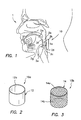
- FIG. 1 shows a cross-sectional anatomical view of a human patient 1.
- the patient 1 has an exemplary apparatus 10, which may be any of the embodiments described herein, located within the patient's oropharyngeal region 1a in order to substantially control, reduce, eliminate, or otherwise treat sleep apnea, snoring, and/or other breathing disorders.
- Snoring and sleep apnea are often caused by a combination of narrowness and low muscle tone of the upper airways.
- the tongue 2a may fall back and obstruct the airway, possibly leading to an arousal reaction and disturbing the normal sleeping pattern.
- Other portions of the oropharyngeal region may also collapse.
- the lateral walls 2b of the oropharyngeal region often become excessively lax and block a free flow of air during respiration.
- the relaxed tongue 2a may move inferiorly (down) and posteriorly (back), and/or the lateral walls 2b of the oropharyngeal region may collapse inwardly resulting in a narrower pharynx relative to when the patient 1 is upright.
- One cause for the narrowing of the pharynx in the supine position may be that the oropharyngeal region 1a and hypopharyngeal region, which have low consistencies, collapse because of lack of direct hard tissue support.
- the apparatus 10 may be secured to the pharyngeal region by various methods.
- the apparatus 10 may be sutured to the pharyngeal region, for example with dissolvable sutures that will allow the apparatus 10 to be held in place while the apparatus 10 becomes fixed to the region by means of tissue ingrowth.
- the apparatus 10 may be secured to the region by means of a suitable biocompatible adhesive as are presently known in the art.
- the apparatus 10 may be secured to the region by being surgically implanted into the region, for example, directly beneath the region's mucosal layer, (hereinafter, "submucosally"), for example, by being pulled, with a surgical needle for example, at least partially into and beneath the mucosal layer such that the apparatus at least partially circumscribes the region.
- submucosally directly beneath the region's mucosal layer
- the apparatus 10 may be designed to provide direct support to at least some of these tissues when the patient 1 is supine and asleep.
- the apparatus 10 may be structured so that when placed in the given position in oropharyngeal region 1a, the apparatus 10 will push the tongue forward, and/or push the lateral walls 2b away from one another thereby holding the airway patent or open during the time the human or animal is naturally sleeping.
- the apparatus 10 may be sized and structured to be positioned adjacent the epiglottis 2c of patient 1, e.g., but without coming in contact therewith.
- the apparatus 10 is designed to overlay a posterior wall 2d of the oropharyngeal region 1a and provide an opening force outwardly against opposing lateral walls 2b of the oropharyngeal region 1a.
- the apparatus 10 is designed to rest within a valecullar space 2e and provide a pushing force against the base 2f of the tongue 2a which makes up a portion of the anterior wall 2g of the oropharyngeal region 1a.
- valecullar space 2e is defined as being the space between the anterior wall 2g of the throat and the upper tip 2h of the epiglottis 2c down to the conjunction of the epiglottis 2c with the anterior wall 2g of the pharynx.
- the apparatus 10 is designed in such a manner as to substantially prevent the apparatus 10 from interfering substantially with the normal functioning of the tissue around the apparatus 10, particularly with the normal functioning of the epiglottis 2c.
- the apparatus 10 may include structures (described elsewhere herein) for anchoring or securing the apparatus 10 within the oropharyngeal region 1a in order to prevent the apparatus 10 from migrating away from or out of the given position.
- the apparatus 10 may be structured to closely and flexibly conform to the size and contours of at least a portion of the oropharyngeal region 1a.
- the apparatus 10 may be said to be effective to provide a support substantially equivalent to the support of tissue and/or muscles of an oropharyngeal region in a healthy, toned state.
- the apparatus 10 may be sized and shaped to fit a human patient having a measured anterior-posterior linear distance between the pharyngeal walls, when the patient is awake and not supine, and the tongue and/or other tissues are not fully lax.
- the apparatus 10 may be structured to maintain a radial force or pressure, for example, a substantially constant radial force or pressure, against the oropharyngeal region, specifically against the lateral walls of the oropharyngeal region, the posterior portion of the oropharyngeal region, and/or the base of the tongue.
- the pressure of the apparatus maintained against this region is advantageously sufficient to maintain patency of the oropharyngeal region during natural sleep in a supine position (for example, greater than about ten centimeters (10 cm) of water), and may exert pressure less than that exerted by the surfaces of the oropharyngeal region during swallowing (for example, about four hundred centimeters (400 cm) of water).
- the apparatus may have hoop strength in a range of about five centimeters (5 cm) of water up to about four hundred centimeters (400 cm) of water. It is further noted that the design of apparatus 10 allows for variable hoop strength as measured along different points about the circumference of the appliance of the apparatus.
- the apparatus 10 is designed and structured to allow substantially normal functioning of the oropharyngeal and pharyngeal regions, while maintaining the structural integrity of the apparatus over a long period of time.
- An important consideration in the design of the apparatus 10 includes the requirement that the apparatus 10 substantially maintain its structural integrity and strength despite the highly dynamic, peristaltic motion of the oropharyngeal and hypopharyngeal regions.
- a human being typically swallows an average of two times a minute throughout the day. This equals around two thousand (2000) swallows per day.
- the force of the swallow varies from one and a half to six pounds (1.5-6 lbs.) of pressure, and the force lasts for about 0.1 to about 0.2 second.
- Swallowing also includes the involuntary apposition of the soft palate to the posterior pharyngeal wall, which is believed to last almost a second and producing a pressure of about one hundred sixty millimeters of mercury (160 mm Hg) and initiate pharyngeal peristalsis, i.e., the wavelike muscular contractions that move food along the alimentary canal in the pharyngeal region.
- This moving front of contraction passes through the pharyngeal constrictors in sequence, traversing the pharynx and hypopharynx at about fifteen centimeters per second (15 cm/s) to reach the upper esophageal sphincter in about one second.
- the hypopharyngeal contraction lasts about 0.3 to about 0.5 seconds and generates an intraluminal pressure of two hundred millimeters of mercury (200 mm Hg).
- the apparatus 10 may be designed to flex and contract along with this wave-like motion of the various muscles in the oropharyngeal and hypopharyngeal region.
- the apparatus 10 may be available in a range of radial forces and sizes in order to suit different individuals.
- each of the embodiments described herein may be made of resilient and elastic biocompatible materials and all edges and surfaces may be smooth and free of sharp portions, burrs, and/or contaminants.
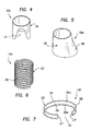
- FIGS. 2-6 show various embodiments of the apparatus 10 that are generally cylindrical or tubular in structure. Except as expressly described herein, each of the apparatus 10a-10e, shown in FIGS. 2-6 respectively, is similar to apparatus 10 and is structured, unless otherwise noted herein, to be utilized for the treatment of sleep apnea, snoring, and/or other breathing disorders, as hereinabove noted.
- apparatus 10a is an appliance 12 structured to fit substantially entirely within the oropharyngeal region and at least partially within the valecullar space and/or extending no higher than the upper surface of the base of the tongue in the anterior portion of the apparatus 10a.
- the posterior portion of the apparatus 10a may be designed to provide additional support above the oropharyngeal region.
- the appliance 12 defines a central open or hollow space 12a and may be made of any suitable biocompatible material, for example, stainless steel, Nitinol, Elgiloy, or other metals, plastics (polymeric materials), and the like, and composites and/or combinations thereof.
- FIG. 3 shows an apparatus 10b including a substantially cylindrical appliance 14 similar to appliance 12, with the most significant difference being that appliance 14 includes a mesh, braid, weave, or knit, for example a woven fabric, polymer, and/or wire mesh.
- the mesh appliance 14 defines a central open or hollow space 14a and includes wires 14b made from a super-elastic material, for example, a nickel titanium alloy (to be described in more detail elsewhere herein), such as the alloy known as Nitinol.
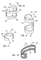
- FIG. 4 shows an additional apparatus 10c, similar to apparatus 10a, including a solid cylindrical appliance 16 including a feature of a cut-out region 17 defined in the appliance 16, the cut-out region being appropriately sized, shaped, and positioned to accommodate natural movements and functions of the epiglottis of a patient (not shown).
- the apparatus 10c may be fitted to a patient with cut-out portion 17 facing an anterior wall of the oropharyngeal region. The epiglottis is therefore free to move inwardly and outwardly of the appliance by means of the cut-out region.
- FIG. 5 shows yet another apparatus 10d, including an appliance 18 having a relatively wider diameter distal or lower portion 19 that may function to anchor or hold the appliance 18 within the valecullar space.
- the apparatus 10d When in use, the apparatus 10d is anchored at portion 19 within the vallecular space allowing the epiglottis to function normally within the relatively wider hollow area defined by the lower portion 19.
- FIG. 6 shows a further embodiment, specifically an apparatus 10e generally including an appliance 20 having a helical or spiral spring including coils 22 formed, for example, from a super-elastic material, as described elsewhere herein.
- FIGS. 7-11 show various other embodiments of implants that are generally non-circumferentially enclosed in structure. Instead, the implants generally define a "C" shape or other open structure, which may define a portion of a circle, ellipse, or other discontinuous periphery. Except as expressly described herein, each of the apparatus 10f-10j, shown in FIGS. 7-11 respectively, may be constructed using materials and/or methods similar to apparatus 10 and/or may be structured, unless otherwise noted herein, to be utilized for the treatment of sleep apnea and/or snoring as herein noted.
- apparatus 10f that includes an appliance 26 that is non-circumferentially enclosed in structure.
- apparatus 10f unlike apparatus 10a-10e, includes spaced apart end portions 27 defining a gap 32, and a closed or intermediate portion 34 between the ends portions 27.
- the end portions 27 may be rounded, as shown, or may have other desired shapes.
- the appliance 26 may be described as a substantially C-shaped member 35 defined by a pair of resilient, flexible wire struts 36a and 36b connected at the end portions 27 to define an enclosed, endless loop.
- the struts 36a and 36b may have any suitable transverse cross-section, for example, a circular, oval, rounded, flattened or other transverse cross-section.
- the C-shaped member 35 is formed from a wire or ribbon that forms a continuous loop as shown, defining an open interior space 38.
- the appliance 26 is structured to be positioned within the oropharyngeal region with the end portions 27 bearing against and providing an opening force against the lateral walls of the oropharyngeal region. It is contemplated that the apparatus 10f may be alternatively positioned such that the appliance 34 rests substantially within or entirely within the valecullar space and presses against the base of the tongue along closed portion 34.
- the end portions 27 Upon contraction of the oropharyngeal region, for example, during swallowing, the end portions 27 will be temporarily forced toward one another by the muscles in the oropharyngeal region, and may or may not overlap or contact one another.
- the flexibility and relative spacing of the struts 36a and 36b allow the appliance 34 to contract and expand in the vertical direction as necessary, for example in conjunction with peristalsis of the pharyngeal walls upon swallowing.
- each of the embodiments of implants 10f-10j may be formed from highly elastic, biocompatible materials.
- each of the implants 10f-10j may be formed from an elastic or a super-elastic material, e.g., a nickel titanium (NiTi) alloy, such as the alloy known as Nitinol.
- NiTi nickel titanium
- Nickel titanium also known as Nitinol
- shape memory alloys A thermoelastic martensitic phase transformation in the material is responsible for its extraordinary properties. These properties include the shape memory effect, super-elasticity, and high damping capability.
- Nitinol has the ability to absorb large amounts of strain energy and release it as the applied strain is removed. Nitinol also has excellent torqueability and kink resistance, which is a useful feature for the apparatus and methods described herein due to the dynamic nature of the oropharyngeal and hypopharyngeal regions.
- super-elastic Nitinol alloys provide a substantially constant force over a large strain range.
- the present apparatus may be formed from a Nitinol material with a ratio of the two constituents, nickel and titanium, at about fifty percent (50%) atomic percent each (e.g., about fifty five percent (55%) percent by weight of nickel).
- Nitinol may be modified by changes in alloy composition, mechanical working, and heat treatment, as known to those of ordinary skill in the art.
- the specific alloy used in the apparatus described herein may be selected mainly for its super-elastic effect rather than its shape memory effect, however, temperature activated shape memory may also be used to control the bias or shape of the apparatus, e.g., upon being exposed to body temperatures within a patient.
- Super-elastic Nitinol alloys may be used in the apparatus described herein to take advantage of a stress-induced martensitic transformation in order to achieve extreme amounts of flexibility and kink resistance. It is known that an alloy of nickel and titanium may behave super-elastically if its Active A f temperature (the temperature above which the material has undergone substantial transformation from its martensitic to its austenitic state) is just below the use temperature. For example, alloys that are intended to be super-elastic at room temperature are generally produced with their Active A f temperatures just below room temperature in the range of about zero to about twenty degrees Celsius (0-20°C).
- a super-elastic material will not be super-elastic at all temperatures, but will exhibit good super-elastic properties in a temperature window extending from the Active A f temperature up to a temperature that is about fifty degrees Celsius (50°C) above Active A f . Therefore, a material with an Active A f of about fifteen degrees Celsius (15°C) will exhibit good super-elasticity up to about sixty five degrees Celsius (65°C), which means that the material will exhibit good super-elasticity at both ambient or room temperature and body temperature (37°C).
- Nitinol is a useful material for the apparatus described herein also due to its excellent biocompatibility, very high corrosion resistance, and excellent cytocompatibility.
- the nickel in nickel/titanium alloy is chemically joined to the titanium in a strong intermetallic bond, so the risk of reaction, even in patients with nickel sensitivity, is extremely low.
- Nitinol is not considered a fibrosis-inducing material. Additional details on nickel titanium alloys are known to those of ordinary skill in the art and are provided, for example, in U.S. Patent No. 6,306,141 to Jervis .
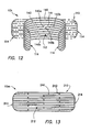
- FIGS. 8-10 show alternative embodiments of implants similar to the embodiment shown in FIG. 7 in that the appliance is non-circumferentially enclosed as defined elsewhere herein.
- an apparatus 10g that generally includes a cuff-shaped appliance 50.
- appliance 50 includes spaced apart end portions 27g defining a gap 32g, and closed portion 34g.
- apparatus 10g includes relatively wide, opposing outer peripheral portions 56a and 56b, that define flattened bands, rather than struts 36a and 36b.
- the outer peripheral portions 56a and 56b define an open interior space 58. Relative to apparatus 10f, this particular design generally allows greater surface contact with oropharyngeal tissues as well as greater hoop strength or opening pressure.
- FIG. 9 shows an apparatus 10h including a cuff-shaped appliance 60 similar to appliance 50 for accommodating a patient with different needs, for example, a patient having a longer, more narrow oropharyngeal region.
- Appliance 60 includes spaced apart end portions 27h defining a gap 32h and closed portion 34h.
- FIG. 10 shows another apparatus 10i generally similar to the embodiment shown in Fig 8 .
- apparatus 10i includes a mesh, braid, knit, or woven structure, which may provide increased flexibility and/or facilitate natural, non-fibrotic, tissue ingrowth to restrict or prevent migration of the apparatus 10i.
- the appliance 64 includes an outer peripheral portion 66 made of a woven mesh wire for example, defining an interior space 68.
- FIG. 11 shows yet another apparatus 10j, including a non-circumferential cuff-shaped appliance 82 having spaced apart end portions 27j defining a gap 32j.
- appliance 82 does not include interior space 58, but is instead substantially solid as shown.
- appliance 82 may include one or more through apertures 87 for facilitating natural, non-fibrotic, tissue ingrowth through the appliance 82.
- FIGS. 12-21 show various embodiments of implants that are generally planar when in a resting or non-deployed state, for example, when the implant is located outside of the oropharyngeal region of a patient in a rest position. Except as expressly described herein, each of the apparatus 10k, 10m, 10n, 10p and 10q, 10s, 10t, 10u, 10v and 10w shown in FIGS. 12-21 respectively, may be constructed similar to apparatus 10 and is structured, unless otherwise noted herein, to be utilized for the treatment of sleep apnea and/or snoring as described elsewhere herein.
- apparatus 10k generally includes an appliance 110 having a flat or substantially planar configuration (represented by phantom lines) that is flexible to achieve an arched or curved configuration (shown in solid line). Like the embodiments shown in FIGS. 7-11 , the apparatus 10k defines a non-circumferential configuration when in the deployed state. Stated differently, the apparatus 10k may be biased to the substantially planar configuration, but may be sufficiently resilient and/or flexible to be directed to the curved configuration, e.g., to allow delivery and/or implantation within the oropharyngeal region of a patient.
- the appliance 110 includes a body portion 112 and end portions 114 spaced apart by the body portion 112.
- the appliance 110 may be in any suitable form, such as, for example, a substantially rectangular form (shown in FIG. 12 ), a substantially circular form, a substantially oblong form, a substantially oval form or a substantially elliptical form or the like configuration.
- the appliance 110 is structured to exert a sufficient force, e.g., a sufficient substantially constant radial force, on the oropharyngeal region, particularly against the lateral walls of the oropharyngeal region, to maintain or cause the airway passing through the region to be patent, so that it is substantially open or unobstructed.
- the appliance 110 is structured to take on a deployed configuration when located within the oropharyngeal region such that the end portions 114 are spaced apart from each other by other than the body portion 112.
- the end portions 114 may be spaced apart by the epiglottis or a portion of the anterior or posterior wall of the oropharyngeal region.
- the apparatus 110 is structured to be sufficiently resilient and flexible to allow for normal dynamic movement or motion of the oropharyngeal region with little or no loss in desirable properties, such as hoop strength and the like, over an extended period of wear.
- the apparatus 10k may be formed entirely from a unitary flat sheet of material that is laser cut into the desired configuration. Using a flat elastic or super-elastic sheet of material or a sheet pre-curved to a diameter larger than that of the oropharyngeal region of the human or animal, the apparatus 10k, once implanted into the oropharyngeal region, applies substantially continuous opening pressure to the oropharyngeal walls, for example, the lateral walls of the oropharyngeal region.
- Appliance 110 may have a longitudinal length (from one end portion 114 to the other end portion 114) between about forty millimeters (40 mm) and about ninety millimeters (90 mm) in the substantially flat configuration, and a lateral height of between about ten millimeters (10 mm) and about fifty millimeters (50 mm).
- the dimensions of appliance 110 may be selected based on individual patient need.
- the appliance is designed such that the effective non-constrained diameter of the appliance, when deployed, is greater than about thirty two millimeters (32 mm).
- Appliance 110 includes a plurality of flexible wire or ribbon struts 140, which may extend between the radiused end portions 114 extending along a substantial portion of the length of the appliance 110.
- the appliance 110 may include between about two (2) and about fifty (50) struts or more, or between about six (6) and about twenty (20) struts, such as about ten (10) struts.
- each of the struts 140 has a thickness (into the sheet) of about 0.005 inch and a width (parallel to the lateral height) of about 0.010 inch.
- This design has been found to provide the required flexibility and resiliency in at least three dimensions or directions of motion, and, in addition, twisting motion, without exhibiting significant fatigue over an extended period of wear/time in service requiring dynamic movement, such as in the oropharyngeal region.
- the number, thickness, and/or width of the struts 140 may be varied to produce a desired opening pressure (e.g., hoop strength) on the base of the tongue or to reduce or increase the surface area of the struts 140 which are in contact with the oropharyngeal walls.
- This design also may allow improved vertical collapse/deformation of the oropharyngeal region, for example, allowing peristalsis type movement during swallowing.
- the appliance 110 When provided in an oropharyngeal region of a patient for the treatment of sleep apnea and/or snoring, the appliance 110 is curved with a convex surface pressing against the tissues to be supported, particularly the lateral walls of the oropharyngeal region and/or the base of the tongue.
- the appliance 110 is structured to be self-expanding with a controlled length during such expansion. This may be achieved by suitable selection of super-elastic materials, such as Nitinol, and appropriate selection of strut length and other dimensions.
- the appliance 110 may also be structured to have a relatively atraumatic nature of all surfaces thereof and of the curved end portions.
- the appliance 110 may be structured to exhibit the ability to be delivered in a minimal diameter access manner by rolling the appliance 110 onto itself within a catheter, cannula, inserter tube, and the like.
- the appliance 110 may be tailored to be effective in a variety of patients and in a variety of different body regions that may benefit from the consistent support provided by such an appliance.
- the size and structure of the appliance 100 may be selected to accommodate a specific need.
- the amount of force provided by the appliance 100 may be modified by appropriate selection of the number of struts, width and/or thickness of struts, and/or surface area covered by the struts and/or the like factors.
- the appliance 110 may become more compliant and may move and/or flex with less radial force exerted thereby and/or may flex to a greater extent without permanent deformation.
- a portion of appliance 110 may be modified such that it may function to anchor or secure the appliance in place.
- an outer or peripheral strut 140a may be configured to achieve a "fluted" configuration (not shown).
- one or more of the struts may be shaped as wave forms or s-shapes.
- cushioned end members may be provided on the end portions 114 of the appliance 110 in order to enhance comfort and/or proper fit.
- An optional feature of the apparatus 110 is shown at 141 for facilitating anchoring of the apparatus 10k in the given position. More specifically, at least one of the struts 140b may be configured to form barbed portions 145a and 145b for enhancing secure attachment of the appliance 110 to the posterior wall of the oropharyngeal region. It is also contemplated that other features or methods for securing the apparatus 10k in the given position may be provided. For example, surfaces of the apparatus 10k may be coated with a biologically compatible glue or adhesive.
- FIG. 13 shows another apparatus 10m including appliance 210 for treating sleep apnea and/or snoring that may be generally similar to apparatus 10k.
- An additional feature shown on apparatus 10m is the addition of spacing portions 242, positioned and structured to maintain a spaced apart relationship between adjacent struts 240 when apparatus 10 is in the oropharyngeal region of a patient.
- Appliance 210 includes end portions 214 and body portion 212, also similar to the apparatus 10k.
- FIGS. 14 and 15 show apparatus 10n and 10p respectively, for treating sleep apnea and/or snoring that may also be similar to apparatus 10k and 10m, with the most significant distinction being that apparatus 10n and 10p are substantially oval or elliptical rather than rectangular in shape.
- Apparatus 10n generally includes appliance 310 including rounded end portions 314 joined by an intermediate body portion 312, and a plurality of spaced apart struts 340.
- Apparatus 10p generally includes appliance 410 including rounded end portions 414 joined by an intermediate body portion 412, and a plurality of spaced apart struts 440 and spacing portions 442.
- FIG. 16 shows yet another apparatus 10q for treating sleep apnea and/or snoring that includes an appliance 510 having a substantially elliptical shape and including a plurality of bowed or arched struts 545 that converge at end portions 514.
- FIGS. 17-21 additional alternative embodiments of implants or stents are shown. Like the embodiments shown in FIGS. 12-16 , these embodiments are typically planar in structure when at rest and not deployed in the oropharyngeal region of a patient. Alternatively, these embodiments may be biased to a curved configuration, e.g., having a radius of curvature larger than the oropharyngeal region. A significant distinction between the embodiments shown in FIGS. 12-16 and the alternative embodiments shown in FIGS. 17-21 , is that the latter embodiments are each defined a single continuous loop.
- FIG. 17 shows an apparatus 10s for treating sleep apnea and/or snoring including a substantially cross-shaped appliance 610, defined by a single loop element 612.
- the appliance 610 may be made, for example, from 0.010 inch to 0.024 inch diameter Nitinol superelastic round wire or cut, e.g., photoetched from a single sheet of material, such as a sheet of a Nitinol superelastic alloy material having a sheet thickness of about 0.010 inch to about 0.100 inch.
- the appliance 610 may have a lateral height H along a vertical axis of about ten millimeters (10 mm) to about fifty millimeters (50 mm), and a longitudinal length L along a horizontal axis of about forty millimeters (40 mm) to about ninety millimeters (90 mm) allowing an effective non-constrained diameter of greater than about thirty two millimeters (32 mm).
- the cross-shaped appliance 610 is substantially symmetrical about its vertical and horizontal axes.
- Appliance 610 includes vertical portions 616a and 616b each defining an angle ⁇ , and horizontal portions 618a and 618b each defining an angle ⁇ .
- vertical portions 616a and 616b define a peak-to-peak measurement (i.e., height H) of about twenty five millimeters (25 mm), and horizontal portions 618a and 618b define a peak-to-peak measurement (i.e., length L) of about fifty millimeters (70 mm).
- each of vertical portions 616a and 616b defines an angle ⁇ of about fifteen degrees (15°) and each of horizontal portions 618a and 618b defines an angle ⁇ of about six degrees (6°).
- Appliance 610 is structured to be placed in the oropharyngeal region in a position such that horizontal portions 618a and 618b rest against and provide support to the lateral walls of the oropharyngeal region.
- the vertical axis of the apparatus 610 generally defined by vertical portions 616a and 616b, are disposed against or adjacent the posterior wall of the oropharyngeal region.
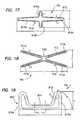
- FIG. 18 shows yet another apparatus 10t for treating sleep apnea and/or snoring that may be similar to apparatus 10s in that it is defined by a single loop element 712 of round wire or cut from a single sheet of material, for example, a Nitinol alloy.
- apparatus 10t includes a substantially X-shaped appliance 710 having a length L and a height H.
- Appliance 710 includes multiple leg portions 717a, 717b, 717c and 717d extending from a generally central region 720, wherein paired leg portions 717a and 717c and paired leg portions 717b and 717d, both define an angle ⁇ .
- appliance 710 has a length L of about fifty millimeters (50 mm) and a height H of about twenty five millimeters (25 mm), and angle ⁇ is about thirty six degrees (36°).
- Appliance 710 is structured to be placed in the oropharyngeal region in a position such that leg portions 717a, 717b, 717c and 717d rest against and provide support to the lateral walls of the oropharyngeal region, and the generally central portion 720 is disposed against or adjacent the posterior wall of the oropharyngeal region.
- FIG. 19 shows yet another apparatus 10u for treating sleep apnea and/or snoring that may be similar to apparatus 10s in that it is defined by a single loop element 812 cut from a single sheet of material, for example, a Nitinol alloy.
- Apparatus 10u includes an appliance 810 having a relatively narrow, generally central body portion 814 (having height H 1 ) terminating at relatively wide end portions 816a and 816b (having height H 2 ), and a length L. End portions 816a and 816b define angle ⁇ as shown.
- appliance 810 may have a length L of about fifty millimeters (50 mm), a height H 1 of about ten millimeters (10 mm), a height H 2 of about thirty five millimeters (35 mm), and an angle ⁇ of about seventy five degrees (75°).
- Element 812 may have a width W 1 at generally central portion 814 and a width W 2 of about five millimeters (5 mm) at end portions 816a and 816b.
- Appliance 810 is structured to be placed in the oropharyngeal region in a position such that end portions 816a and 816b rest against and provide support to the lateral walls of the oropharyngeal region, and the generally central body portion 814 is disposed against or adjacent the posterior wall of the oropharyngeal region.
- FIG. 20 shows yet another apparatus 10v for treating sleep apnea and/or snoring that includes an appliance 910 defined by an endless loop element 912, and including a generally central body portion 914, and multiple end portions 916a, 916b, 916c and 916d. As shown, adjacent end portions define an angle ⁇ . Appliance 910 further includes a vertical portion 950 that defines an angle ⁇ .
- Appliance 910 is structured to be placed in the oropharyngeal region in a position such that multiple end portions 916a, 916b, 916c and 916d rest against and provide support to the lateral walls of the oropharyngeal region, and the generally central body portion 914 is disposed against or adjacent the posterior wall of the oropharyngeal region.
- FIG. 21 shows yet another apparatus 10w for treating sleep apnea and/or snoring that includes an appliance 1010 that is somewhat similar to appliance 910 in that appliance 1010 includes a generally central body portion 1014 and multiple end portions 1016a, 1016b, 1016c and 1016d. Appliance 1010 has somewhat different proportions, including a relatively wide upper central portion 1019 that is configured to provide enhanced tissue support to portions of the posterior wall of the oropharyngeal region, relative to tissue support provided by appliance 910.
- FIGS. 22-23 show other embodiments of implants or stents for treating sleep apnea and/or snoring. Like the embodiments shown in FIGS. 12-21 , these embodiments are typically planar in structure or curved to a diameter in excess of thirty two millimeters (32 mm) when at rest and not deployed in the oropharyngeal region of a patient.
- FIG. 22 shows an apparatus 10x including a substantially symmetrical appliance 1110 including a substantially linear body portion 1112 and a plurality of struts 1118 extending from the body portion 1112, for providing support to the oropharyngeal tissues.
- the number and length of struts 1118 may be selected based on a particular patient need or other parameters.
- appliance 1110 may have an upper portion 1120 having about two pairs of struts 1118 defining a tip to tip length L 1 of about forty two millimeters (42 mm), and a lower portion 1122 having about five pairs of struts 1118 defining a tip to tip length L 2 of about sixty two millimeters (62 mm).
- FIG. 23 shows an apparatus 10y that is similar to apparatus 10x.
- apparatus 10y includes an appliance 1210 including a body portion 1212 and struts 1218 that are offset from one another along body portion 1212.
- apparatus 10z is structured to be effective in maintaining patency of the airway of a patient 1, for example, the oropharyngeal region 1a of a patient.
- apparatus 10z is specifically structured to be at least partially, and in some cases substantially entirely submucosally, implantable into the pharyngeal region, for example the oropharyngeal region, of the patient.
- Apparatus 10z includes a single elongated element 1401 having end portions, for example, rounded end portions 1406 and a body portion 1408 extending or connected therebetween.
- end portions 1406 are structured to facilitate implantation, for example, surgical implantation, of the element 1401.
- end portions 1406 may include appropriately sized apertures 1410 for receiving suturing thread.
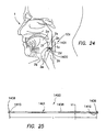
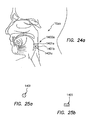
- the element 1401 may have a rounded cross-section such as shown in FIG. 25A , or a polygonal cross section, for example a rectangular cross section, such as shown in FIG. 25B .
- element 1401 may have a length L between about fifty millimeters (50 mm) and about seventy millimeters (70 mm) and a width W between about two millimeters (2 mm) or less and about six millimeters (6 mm).
- Dimensions of the appliance 1400 may be at least in part based upon, for example, the size or diameter of the patient's pharyngeal region and the specific portion of the pharyngeal region to be supported by the apparatus 10z.
- a typical area of support as mentioned elsewhere herein, is the area encompassing, at least, a portion of one or more of the lateral walls of the oropharyngeal region.
- Appliance 1400 may be formed from Nitinol or other suitable, flexible, elastic biocompatible material, e.g., as discussed elsewhere herein.
- the element 1401 is designed to be surgically implantable in the pharyngeal region, at least partially circumscribing the region, and at least partially or substantially entirely, beneath the mucosal layer thereof.
- the appliance 1400 may also be at least partially sutured to the pharyngeal tissues, for example, at end portions 1401a of the element 1401, and/or secured to the oropharyngeal tissues by means of a biocompatible adhesive.
- appliance 1400 is shown sized to be placed at least partially circumscribing an interior hollow passage (representing a cross-section of the airway of the patient) defining the pharyngeal region.
- This view (as well as views shown in FIG. 27 and FIG. 28 ) is a simplified representation of a cross-section of the oropharyngeal region 1a, with posterior wall 2d and anterior wall 2g, (which includes the base 2f of the tongue 2a) and opposing right and left lateral walls 2b.
- This placement of appliance 1400 is effective in providing support to the lateral walls 2b of the oropharyngeal region 1a.
- the appliance 1400 is shown substantially entirely submucosally implanted.
- appliance 1400 is shown sized to be placed circumscribing, at least one full circumference of, the interior hollow space defined by the pharyngeal region.
- the appliance 1400 is sized to traverse the base 2f of the tongue 2a, for example, beneath the mucosal tissue thereof.
- the appliance 1400 is shown partially submucosally implanted.
- FIG. 24A shows another apparatus, generally at 10za that is substantially similar to apparatus 10z, except that apparatus 10za includes an appliance 1400a including a plurality of elongated, spaced apart elements, for example at least two, or three, or even more spaced apart elements 1401a, 1401b, and 1401c, depending upon the specific needs of a particular patient. Except as indicated elsewhere herein, it is to be appreciated that elements 1401a, 1401b and 1401c are structured to be placed, for example, at least partially submucosally, implanted in a manner as described hereinabove with respect to element 1401.
- Each element 1401 a, 1401b, and 1401c may be substantially, entirely independent, or unitary, in structure with respect to each other element 1401 a, 1401 b, and 1401 c.
- the multiple elements 1401a, 1401b, and 1401c maybe secured to each other by suitable means, for example, suturing, wire, ribbon or the like, for substantially maintaining the spaced apart relationship between the elements 1401a, 1401b, 1401c when the elements 1401a, 1401b, 1401c are positioned within and secured to the oropharyngeal region.
- a method for maintaining patency of an oropharyngeal region.
- the method may include at least partially submucosally placing at least one elongated element within the pharyngeal region, for example, within the oropharyngeal region in one or more strategic locations, wherein the placement thereof may cause the region to be stiffened or strengthened against collapse during natural sleep.
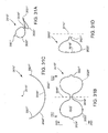
- FIG. 28 shows a simplified view of the oropharyngeal region 1a of a patient, having apparatus 10zb submucosally implanted therein.
- Apparatus 10zb includes one or more magnetic components 1500a and 1500b, structured and designed to be effective to provide a magnetic field useful for providing gentle, substantially constant and continuous resistance against collapse of the pharyngeal walls, particularly the lateral walls 2b of the oropharyngeal region 1a, for example during natural sleep, while allowing substantially normal functioning of the pharyngeal region, for example during swallowing.
- the two magnetic components 1500a, 1500b are strategically placed within the oropharyngeal region 1a such that like magnetic poles (i.e., repellant magnetic poles) are positioned substantially facing one another to create a magnetically repellant force therebetween (indicated in simplified form by arrows 1502).
- the repellant force caused by the strategically placed magnetic components 1500a and 1500b is effective for providing an opening force within the oropharyngeal region, thereby maintaining patency of the region during natural sleep while still allowing constriction of the region during swallowing.
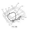
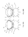
- FIG. 29A through FIG. 29E show various views of another embodiment of an apparatus 2010, which generally includes an implant, stent, or appliance 2012.
- the apparatus 2010 may include other features, such as the needle 2030 and suture 2032 shown in FIG. 29G or other delivery device (not shown), as described elsewhere herein.
- the appliance 2012 has a generally "bow-tie” shape in a generally vertical direction, i.e., along a vertical axis 2016, as best seen in FIG. 29B .
- the apparatus 2012 has a curved shape in a generally horizontal plane that intersects the vertical axis 2016, as best seen in FIG. 29C .
- the appliance 2012 generally includes a vertically narrow central region 2018 flanked by vertically wide or broadened first and second regions 2020, i.e., generally defining the "bow-tie” shape.
- the central region 2018 may curve around vertical axis 2016, and the broadened regions 2020 may curve away from the vertical axis 2016.
- the central region 2018" and the broadened regions 2020" may both curve around the vertical axis 2016," e.g., in a substantially continuous "C" shaped curve, which may be a portion of a circle or ellipse.
- one or both broadened regions 2020 may terminate in a rounded tip 2021, e.g., that may be vertically narrower than the broadened regions 2020 and/or vertically narrower than the central region 2018.
- the tip(s) 2021 may curve relative to the broadened regions 2020, e.g., curving away from the vertical axis 2016 within the horizontal plane. As shown, the tips 2021 curve within the horizontal plane at a tighter radius of curvature than the broadened regions 2020, as shown in FIG. 29C .
- the appliance 2012 may be formed from a unitary, continuous, closed loop element 2014 surrounding and/or substantially enclosing an open area 2022, e.g., made from a round, square, or other cross-section loop of wire loop.
- a wire may be bent or otherwise formed into the desired shape and the ends may be coupled to one another, e.g., butt welded or soldered, sonic welded, heat sealed, fused, bonded with adhesive, crimped within a collar, captured within a section of shrink tubing, and the like, depending upon the material of the wire used.
- the wire may be heat treated or otherwise treated to program in the desired shape and/or impart the desired elasticity and/or other properties into the resulting apparatus 2010.
- the apparatus 2010 may be formed from a sheet of material, e.g., by laser cutting, machining, etching, and the like, before or after programming a desired shape into the sheet.
- the apparatus 2010 may be structured to be surgically placed in a oropharyngeal region of a patient, generally designated as "OR.”
- OR a oropharyngeal region of a patient
- FIG. 29E a simplified perspective view of the oropharyngeal region OR is shown, showing posterior wall PW, anterior wall AW, and lateral walls LW of the oropharyngeal region OR.
- the broadened regions 2020 of the appliance 2012 arc outwardly from the generally central region 2018.
- Broadened regions 2020 may be shaped to generally conform to the natural contours of the oropharynx and/or to provide support thereto.
- the broadened regions 2020 may be located beneath the mucosal layer of the posterior and/or lateral oropharyngeal walls or may simply abut the posterior and/or later oropharyngeal walls, as described elsewhere herein.
- the narrow tips 2021 may have an enhanced bias relative to the broadened regions 2020, e.g., to enhance securing the appliance 2010 within the oropharyngeal region OR.
- the portions of the wire defining the broadened regions 2020 may extend at least partially laterally or diagonally relative to the longitudinal axis 2016.
- the broadened regions 2020 may include curved portions extending from the tips 2021 diagonally relative to the vertical axis 2016. Such lateral portions may facilitate collapsing the broadened regions 2020 when the appliance 2012 is directed through a relatively small opening, such as a puncture through a ligament or other tissue structure, as described elsewhere herein.
- the appliance 2012 may be sufficiently resilient and/or elastic such that the broadened regions 2020 may be collapsed vertically from their relaxed state (shown in FIG. 29B ), e.g., when directed through a relatively small opening, yet biased to resiliently expand back towards the relaxed state after passing through the opening.
- the portion of the open area 2022 within the broadened regions 2020 may define a relatively large surface area, which may enhance apposition between the broadened regions 2020 and adjacent tissue, as described elsewhere herein.
- the broadened regions 2020 may have different shapes than that shown.
- the broadened regions may have diamond shapes in the relaxed state, e.g., extending between the central region and the narrow tips.
- the broadened regions may have circular or elliptical shapes, e.g., with or without the narrow tips.
- the broadened regions may have generally triangular shapes, e.g., within one of the apices of the triangles oriented towards the central region and bases of the triangles defining ends of the appliance.
- the broadened regions may have generally rectangular, square, or other geometric shapes that are larger than the narrower central region.
- the open area 2022' of the appliance 2010' may be covered, for example, with a mesh, fabric, braid, membrane or other material.
- the material may include any of the material described elsewhere herein, e.g., such as those from which the appliance 2010' may be formed, or other materials, such as Dacron® and the like. Such material may enhance tissue ingrowth after implantation.
- the material may be coated or otherwise provided with therapeutic or other compounds, e.g., to enhance tissue ingrowth, healing, and the like.
- a needle 2030 may be coupled to one of the narrow tips 2021, e.g., by a suture or other filament 2032 to provide a system for delivering the appliance 2010 into the oropharyngeal region OR (not shown, see FIG. 29F ).
- the needle 2030 may have a "U" or other shape to facilitate introduction through a ligament or other tissue structure adjacent the oropharyngeal region OR or other implantation site.
- the suture 2032 may be a double suture looped through the narrow tip 2021 such that, the suture 2032 may be cut or otherwise severed at one location to allow the suture 2032 and needle 2030 to be removed, e.g., after implanting the appliance 2010, as described further below.
- a catheter, cannula, or other tubular member may be provided within which the appliance 2012 may be loaded, e.g., after manufacturing or immediately before implantation.
- a suture, tool, and the like may be coupled to one of the narrow tips 2021 and used to pull the appliance 2012 into a lumen of a first end of a cannula, the broadened regions 2020 being resiliently compressed as the appliance 2012 is pulled therein. As the appliance 2012 is pulled into the cannula, the appliance 2012 may also be substantially straightened within the horizontal plane.
- the appliance 2012 may be deployable from the cannula using a plunger or other pusher device within the cannula, e.g., adjacent the narrow tip 2021 used to pull the appliance 2012 into the cannula.
- a plunger or other pusher device within the cannula, e.g., adjacent the narrow tip 2021 used to pull the appliance 2012 into the cannula.
- another suture, tool, and the like may be coupled to the narrow tip 2021 closest to the first end of the cannula and used to pull the appliance 2012 back out of the cannula, whereupon the broadened regions 2020 may resiliently expand.
- a generally "bowtie" shaped appliance 2012 such as those shown in FIGS. 29A-29F , may be designed to be surgically implanted into an oropharyngeal region OR of a patient using direct visualization and a curved, e.g., "U" shaped, needle 2030 and suture 2032, such as that shown in FIG. 29G .
- the suture 2032 may be tied to or otherwise coupled to either narrow tip 2021 of the appliance 2012, e.g., by looping the suture 2032 around the wire of the appliance 2012 and through an eye of the needle 2030, and securing the ends together.
- one end of a suture may be attached to the narrow tip 2021 using a knot, for example, one that is tapered and will easily come apart when cut (e.g. a "fisherman's" knot), and the other end of a suture may be attached to the needle 2030, e.g., also by knotting.
- a knot for example, one that is tapered and will easily come apart when cut (e.g. a "fisherman's" knot)
- the other end of a suture may be attached to the needle 2030, e.g., also by knotting.
- the needle 2030 (not shown, see FIG. 29G ) may be introduced into the posterior wall of the oropharynx, for example at about one to four centimeters (1-4 cm) above the epiglottis (not shown), and approximately 0.2 cm lateral to the centerline CL.
- the needle 2030 is then pushed through or behind the anterior longitudinal ligament (ALL) located anterior to the spine 2019 so that it emerges from the tissue at the same distance above the epiglottis and approximately 0.2 cm from the centerline on the side opposite that where the needle was introduced, thereby creating passage or opening OP.
- the needle 2030 is then pulled out of the tissue along with sufficient length of suture 2032 to allow it to be grasped and used to pull the appliance 2012 through or behind the ligament (ALL).
- Significant resistance on the needle and suture as they are pulled through the tissue provides assurance that they have passed through or behind the ligament (ALL).
- one half of the appliance 2012 is then pulled through the opening OP through or behind the ligament (ALL) with the curve of the central region 2018 facing in the anterior direction.
- the first narrow tip 2021a is pulled through or behind the ligament, which may cause the narrow tip 2021a to compress vertically to pass through the opening created by the needle 2030 (the size of the opening OP shown not being to scale merely for clarity).
- the design of the appliance 2012 allows the broadened region 2020a to compress vertically, e.g., into a collapsed configuration, to facilitate passage through the opening OP.
- the broadened region2020a may resiliently expand towards its relaxed state.
- the appliance 2012 may be self locating, e.g., in that it is shaped and structured to gently unfold or spring into its appropriate position once it has been correctly placed.
- the suture 2032 is then cut and removed, leaving the appliance 2012 in position such that its central region 2018 remains within the opening OP through or behind the ligament (ALL).
- the portions of the loop element 2014 defining the central region 2018 may extend substantially parallel to one another in or behind the ligament (ALL), and the two broadened regions 2020 may rest against the surface of the mucosal layer of the posterior and lateral walls PW of the oropharyngeal region on both sides of the anterior longitudinal ligament.
- the most lateral ends of the appliance 2012 may also rest against the tongue.
- the appliance 2012 Within a period of time, for example, within about one week, or two weeks or longer, after the surgical implantation, most or all of the appliance 2012 becomes submucosalized, such as shown in FIG. 30B , such that the appliance 2012 resides within the walls of the oropharyngeal region. No longer exposed on the interior surface of the pharyngeal walls, the appliance 2012 has essentially become an internal support structure which underlies the outer mucosal layer.
- the appliance 2012 may subsequently be removed from the patient, e.g., using a similar procedure used for implantation.
- a tool (not shown) may be used to grab or otherwise be coupled to one of the narrow tips 2021, and the tip 2021 may be pulled to direct the opposite broadened region 2020 back through or behind the ligament (ALL).
- the broadened region 2020 may again be compressed vertically, similar to that shown in FIG. 30C , until the broadened region 2020 is pulled completely through or behind the ligament (ALL), whereupon the entire appliance 2021 may be removed.
- an appliance 2012 such as that shown in FIGS. 29A-29E , may be selected for implantation in a patient.
- the appliance 2012 may be made from 0.020" diameter round Nitinol wire and may have a length, i.e., from narrow tip 2021 to narrow tip 2021 along the horizontal plane, of about forty centimeters (40 mm).
- the appliance may be inserted into the patient, while she is under general anesthesia, e.g., by a physician using direct visualization techniques, and a curved, U-shaped needle 2030 and suture 2032, as shown in FIG. 29G .
- a suture end opposite the needle 2030 may be tied to either extreme tip 2021 of the appliance 2012 using a knot (not shown) that may easily come apart when cut, for example, a fisherman's knot.
- the curved needle is introduced into the posterior wall of the patient's pharynx at about two centimeters (2.0 cm) to about two and a half centimeters (2.5 cm) above the epiglottis and approximately 0.2 cm lateral to the centerline.
- the needle is then carefully pushed through the anterior longitudinal ligament so that it emerges from the tissue at the same distance above the epiglottis and approximately 0.2 cm from the centerline of the side opposite that where it was introduced.
- the needle is pulled out of the tissue along with sufficient length of suture to allow it to be grasped and used to pull the appliance through the anterior longitudinal ligament, e.g., as described above with reference to FIGS. 20A-30D .
- Significant resistance on the needle 2030 and suture 2032 as they are pulled through the tissue may indicate that they have passed through the anterior longitudinal ligament.
- one half of the appliance 2012 is then pulled through the anterior longitudinal ligament using the most lateral narrow tip 2021 to facilitate introduction and with the curved, central region 2018 facing in the anterior direction.
- the appliance 2012 While the appliance 2012 is being pulled through the tissue, the appliance 2012 may compress vertically, e.g., into a narrow, substantially linear delivery configuration that facilitates passage through the tissue.
- the appliance 2012 automatically unfolds or opens to regain its resting configuration once passed through the anterior longitudinal ligament.
- the suture 2032 is then cut and removed, leaving the appliance 2012 in position such that its central region 2018 rests in the anterior longitudinal ligament and the broadened regions 2020 rest against the surface of the mucosal layer of the posterior and lateral walls of the oropharyngeal region on both sides of the anterior longitudinal ligament.
- the appliance 2012 thus may make approximately a one hundred eighty degree (180°) rotation around the posterior oropharynx.
- the appliance 2012 may be placed around or behind the anterior longitudinal ligament rather than being inserted through the ligament.
- the appliance 2012 may also extend beyond one hundred eighty degrees (180°), e.g., to provide resistance against posterior collapse of the tongue. After the appliance 2012 has been implanted and its position checked and verified to be acceptable, the procedure may be completed and the patient observed using conventional procedures.
- the appliance 2012 may become submucosalized, e.g., as shown in FIG. 30B .
- the broadened regions 2020 of the appliance 2012 on both sides of the anterior longitudinal ligament are not visible against the surfaces of the right and left oropharyngeal wall.
- the appliance 2012 may be located beneath the outer mucosal layer.
- the patient After the patient recovers from the surgery, she may no longer notice the presence of the appliance 2012 in her throat, even upon swallowing. Moreover, the patient may be able to achieve greater quality sleep at night due the implant, which may increase the patient's energy, e.g., during ordinary activities during the day.
- the apparatus may include an element that provides a magnetic opening force against collapsing pharyngeal, for example, oropharyngeal, tissues.
- the apparatus may include an appliance, such as those described elsewhere herein, that is at least partially magnetized. More specifically, the apparatus may include two or more magnetic elements having like poles facing one another to create a magnetic field that may be utilized to provide a useful opening force to the pharyngeal, for example, oropharyngeal, region.
- methods are provided for maintaining patency of a pharyngeal region, for example, the oropharyngeal region, in order to substantially reduce the occurrence of sleep apnea and/or snoring.
- These methods may include one or more of supporting, strengthening, reinforcing, and/or stiffening tissues of the region that are subject to collapse during natural sleep.
- this may be accomplished by using one or more of the following: injecting an agent into the tissues, e.g., to cause partial necrosis of portions of the tissues in the region, thereby stiffening the region; injecting a liquid or gel agent into the tissues that solidifies within the tissues to provide a reinforcement against collapse of the region; mechanically or chemically irritating the tissues to cause a tissue reaction that firms the tissues of the region; and/or applying a wave energy to the tissues to cause a tissue reaction that firms the tissues of the region, for example, but not limited to ultrasonic energy, radiofrequency energy, thermal energy (either adding thermal energy to the tissues or chilling the tissue by removing thermal energy). Combinations of two or more of these steps may be advantageously employed.
- An exemplary method for maintaining patency of a pharyngeal region generally includes providing an implant, for example elongated element 1401 shown in FIGS. 24 and 25 , in a substantially flat or precurved configuration.
- the implant may include a body portion and end portions spaced apart by the body portion.
- the implant may be implanted, at least partially submucosally, within the pharyngeal region, e.g., within the oropharyngeal region, such that the implant is effective to provide a substantially constant force against at least a portion of each of the lateral walls of the region.
- the step of implanting may include implanting the implant into the pharyngeal region such that the implant is substantially entirely submucosally implanted in the pharyngeal region.
- the member may be implanted into oropharyngeal tissues, e.g., directly beneath the mucosal layer, by using a curved surgical needle to weave the member into and beneath the submucosal tissue.
- the method may include implanting an appliance, such as appliance 2012 shown in FIGS. 29A-29E , into the pharyngeal region of a patient, in a location generally adjacent the epiglottis.
- the appliance 2012 may be implanted through the lateral pharyngeal walls such that the appliance 2012 is located with broadened regions 2020 of the appliance 2012 overlying the lateral walls and generally narrow central region 2018 is located posterior to the pharynx, such as shown in FIG. 29E and FIG. 30A .
- the method further includes placing the appliance 2012 at the surface of the mucosa with pressure against the mucosa allowing the appliance 2012 to submucosalize into the pharyngeal walls over a period of days or weeks as seen in FIG. 30B .
- a method in another embodiment, includes providing an apparatus in the oropharyngeal region of the human or animal, for purposes other than surgery.
- the apparatus may be effective in treating sleep apnea and/or snoring and/or in maintaining patency of the oropharyngeal region during natural sleep of the human or animal, without causing substantial interference with one or more natural functions of the epiglottis.
- each of the apparatus for treating sleep apnea and/or snoring described and shown elsewhere herein are suitable for use in any of the methods described herein. It is to be appreciated, however, that the apparatus used for performing the methods described herein may take other forms as well.
- a conventional stent may be used in maintaining the airway in the pharyngeal region, for example, the oropharyngeal region in an open state, and such use is considered to be within the scope of the methods described herein.
- the apparatus used in the methods described herein may be devices, for example but not limited to, a conventional stent, sized and structured for placement in another region of the human or animal other than the pharyngeal region, for example, the oropharyngeal region.
- a method for maintaining patency of a pharyngeal region of a patient includes providing an apparatus in a first configuration, for example a rolled, coiled, or otherwise compressed configuration; inserting the apparatus into the oropharyngeal region, for example through the oral or nasal cavity of the patient while the apparatus is in the compressed configuration; and, thereafter, allowing the apparatus to reconfigure or expand towards its original relaxed configuration, for example, defining a substantially cuff shape, C-shape, or other suitable deployed configuration, within the oropharyngeal region.
- a first configuration for example a rolled, coiled, or otherwise compressed configuration
- Any suitable deployment assembly useful for inserting the apparatus through the mouth or oral cavity, or nasal cavity of a patient and into the oropharyngeal region may be utilized in accordance with the methods described herein.
- a suitable deployment assembly includes an outer tube (e.g., about ten millimeters (10 mm) diameter) and inner tube (e.g., about eight millimeters (8 mm) diameter) disposed within the outer tube (not shown).
- a retaining clip may be used to fix the tubes in place with respect to each other.
- the appliance for example in a rolled configuration or an axially compressed and/or substantially straightened configuration, may be provided within the outer tube at a distal portion thereof. Graspers, having a manually manipulable proximal portion may be provided through the tubes for assisting in positioning or removal of the appliance.
- the deployment assembly may be advanced past the tongue of the patient until the inner diameter of the outer tube and the rolled appliance passes into the oropharyngeal region.
- the retaining clip may then be removed from the inner tube.
- the graspers may be used to facilitate repositioning of the appliance as necessary or desirable.
- the appliance may be deployed by retraction of the outer tube relative to the inner tube.
- the graspers may be used subsequently to remove the appliance if desired.
- This method generally includes providing a flat or pre-curved member (for example, appliance 110, 210, 310, 410, 510, 610, 710, 810 910, 1010, 1110 or 1120 shown in the drawings), pulling end portions of the flat or pre-curved member together to form a folded member and holding or temporarily securing the end portions together by means of a grasper, clamp, hemostat, suture (for example, a bioresorbable suture), and/or suitable means for temporarily holding the end portions together in contact with one another.
- a flat or pre-curved member for example, appliance 110, 210, 310, 410, 510, 610, 710, 810 910, 1010, 1110 or 1120 shown in the drawings
- a grasper clamp, hemostat, suture (for example, a bioresorbable suture)
- suture for example, a bioresorbable suture
- the method further includes placing the member in the folded or pinched configuration, into the oropharyngeal region, for example by way of the oral or nasal cavity of the patient, and releasing the end portions, thereby allowing the member to expand radially within the oropharyngeal region to provide a substantially constant radial force against the lateral walls of the oropharyngeal region and/or the base of the tongue.
- the method may further include the step of repositioning the member while the member is located within the oropharyngeal region and/or the step of removing the member therefrom. This may be accomplished by folding the member into a rolled or pinched configuration and withdrawing the member from the body region.
- a patient may be treated, e.g., who experiences snoring with apneic pauses, severe daytime hypersomnolence with narcolepsy, and the like.
- a polysomnography may be performed, e.g., to indicate a Respiratory Disturbance Index (RDI) for the patient, which may show severe desaturation, bradycardia, and/or partial or complete absence of stage 3, stage 4, and REM sleep.
- RDI Respiratory Disturbance Index
- An implant such as appliance 1400 shown in FIG.25 may be selected, e.g., having a length of about seventy millimeters (70 mm), a width of about 1.0 mm, and a thickness of about 0.0075 inches (about 0.2mm), for submucosal implantation.
- the appliance 1400 may be introduced into the submucosal tissues beginning in the right lateral pharyngeal region, particularly the right lateral oropharyngeal region.
- the appliance may be introduced submucosally using a curved surgical needle that may be used to pull the appliance into the tissues in a manner that causes the appliance to be substantially concealed within the tissues, with little or no exposure of any portion of the appliance postsurgically.
- the appliance may be guided medially and inferiorly, traveling around the posterior oropharyngeal region and ultimately into the submucosal tissues of the tongue base.
- the tongue base is then traversed and the appliance is brought back along the right lateral oropharyngeal wall.
- the appliance thus makes at least one complete rotation around the pharynx.
- an implant such as appliance 1400 shown in FIG. 25
- the appliance 1400 is made from Nitinol and has a length of about forty millimeters (40 mm), a width of 1.25 mm and a thickness of about 0.5 mm.
- the appliance may be introduced into the submucosal tissues beginning in the right lateral oropharyngeal region.
- the appliance is then guided medially and inferiorly, traveling around the posterior oropharyngeal region and ultimately into the submucosal tissues of the left lateral oropharynx.
- the appliance does not traverse the tongue.
- the appliance thus makes about a one hundred eighty degree (180°) rotation around the oropharynx.
- a first further preferred embodiment of the present invention is an apparatus for implantation within an oropharyngeal region adjacent a ligament, comprising: an implant comprising a substantially continuous loop structure comprising a curved central region between first and second regions in a horizontal plane; the first and second regions being compressible towards one another such that the implant defines a generally "C" shape about a vertical axis extending from the horizontal plane, the first and second regions being biased to open away from the vertical axis within the horizontal plane such that the first and second regions apply a force to dilate tissue adjacent the oropharyngeal region when the implant is disposed within the oropharyngeal region; the central region of the implant being vertically narrow relative to the first and second regions, at least one of the first and second regions being compressible vertically to allow the at least one of the first and second regions to be directed through or behind the ligament adjacent the oropharyngeal region such that the central region is disposed within or behind the ligament, the at least one of the first and second regions being resiliently expandable after passing through or behind the
- At least one of the first and second regions terminates in vertically narrow tip to facilitate introduction of the at least one of the first and second regions through or behind the ligament.
- said implant further comprises a filament coupled to the at least one of the first and second regions, a free end of the filament being advanceable through or behind the ligament for guiding the at least one of the first and second regions through or behind the ligament.
- Said implant may further comprise a needle coupled to the free end of the filament, the needle having a sharpened tip for penetrating through or behind the ligament for advancing the filament through or behind the ligament.
- said central region of the implant is biased to curve around the vertical axis, and wherein the first and second regions are biased to curve away from the vertical axis within the horizontal plane.
- said central region and the first and second regions are biased to curve around the vertical axis within the horizontal plane.
- Said central region and the first and second regions may be biased to a radius of curvature greater than sixteen millimeters.
- a second further preferred embodiment of the present invention is a system for treating sleep apnea, snoring, or other breathing disorders within an oropharyngeal region adjacent a ligament, comprising: an implant including a curved central region between first and second regions within a horizontal plane; and a needle coupled to the first end region by a filament for insertion through a ligament adjacent an oropharyngeal region; the central region being vertically narrow relative to the first and second regions, at least the first region being compressible vertically to allow the first region to be directed through or behind the ligament adjacent the oropharyngeal region when the needle and filament are inserted through or behind the ligament such that the central region is disposed within or behind the ligament, the first region being resiliently expandable after passing through or behind the ligament.
- Said first and second regions may be compressible towards one another within the horizontal plane such that the implant defines a generally "C" shape about a vertical axis extending from the horizontal plane, the first and second regions being biased to open away from the vertical axis within the horizontal plane such that the first and second regions apply a force to dilate tissue adjacent the oropharyngeal region when the implant is disposed within the oropharyngeal region.
- a third further preferred embodiment of the present invention is an apparatus for treating at least one of sleep apnea and snoring in a human or an animal having an oropharyngeal region, the apparatus comprising: an appliance sized and structured to be placed in the oropharyngeal region and being effective in treating at least one of sleep apnea and snoring, the appliance comprising substantially opposing elongated elements together forming an open configuration, each of the elongated elements having a generally centrally located region that is substantially more closely spaced apart from the other elongated element than any other region of the elongated element.
- said open configuration is a double concave loop configuration.
- said open configuration is in the form of a loop having a relatively narrow central portion between relatively broadened portions.
- said two elongated elements comprise a resilient wire.
- said appliance is compressible to a constrained configuration when being introduced into an oropharyngeal region, and is biased to a relaxed configuration when the appliance is so placed in an oropharyngeal region that is larger than the constrained configuration.
- said appliance is structured to substantially conform to the posterior and lateral walls of the oropharyngeal region.
- said appliance is structured to support the tongue from falling back towards the posterior wall.
- said appliance is structured to be placed within the oropharyngeal region such that the generally centrally located region of each elongated element is located in or adjacent the anterior longitudinal ligament of the spine when the appliance is so placed.
- each of the elongated elements includes outwardly extending regions located at first and second ends of each elongated element, the outwardly extending regions being located substantially further spaced apart from the other elongated element than the generally centrally located region.
- This eighth aspect of the third further preferred embodiment of the present invention forms a fourth further preferred embodiment of the present invention.
- said appliance is structured such that the generally centrally located regions of each elongated element are located through or behind the anterior longitudinal ligament of the spine and the outwardly extending regions are located against the right and left posterior and lateral walls of the oropharyngeal region when the apparatus is deployed.
- Said outwardly extending regions may have a structure that promotes mucosalization over the outwardly extending regions when the appliance is deployed.
- said outwardly extending regions have a structure that enables the first and second ends of each of the outwardly extending regions to be located at or in close proximity to the base of the tongue in the anterior portion of the oropharyngeal region.
- said appliance is structured to be collapsible to assume a deformed configuration for facilitating delivery of the appliance into the oropharyngeal region.
- Said elongated elements may have sufficient resiliency to cause the appliance to expand from the deformed configuration to the open configuration after or during deployment of the appliance into the oropharyngeal region.
- said appliance has a length between about thirty millimeters (30 mm) and about one hundred millimeters (100 mm). Said appliance may have a height between about forty millimeters (40 mm) and about ninety millimeters (90 mm).
- said appliance includes enlarged end portions having a height between about ten millimeters (10 mm) and about fifty millimeters (50 mm).
- said appliance includes enlarged end portions configured to rest against the mucosal layer of the posterior oropharyngeal region and on opposing lateral walls of the oropharyngeal region and that are substantially symmetrical in the longitudinal dimension across the posterior and lateral walls of the oropharyngeal region.
- a fifth further preferred embodiment of the present invention is a method for treating sleep apnea or snoring within an oropharyngeal region adjacent an anterior longitudinal ligament, the method comprising: introducing an implant into the oropharyngeal region, the implant comprising a curved central region between first and second regions, the central region being vertically narrow relative to the first and second regions; introducing the first region through an opening through or behind the ligament, the first region compressing vertically from a relaxed configuration as the first region passes through the opening, until the first region passes through the opening, whereupon the first region resiliently expands towards the relaxed configuration, the central region remaining within the opening to maintain the implant within the oropharyngeal region, the first and second regions applying a force to tissue adjacent the oropharyngeal region.
- said implant comprises an endless loop defining the central region and the first and second regions that are relatively wider than the central region.
- said method further comprises inserting a needle through or behind the ligament to create the opening, the needle being coupled to the first region by a filament such that the first region is introduced through the opening by pulling the filament after the needle is inserted through or behind the ligament.
- said introducing the first region through the opening comprises passing the first region into a lateral or posterior wall of the oropharyngeal region and through or adjacent the ligament.
- said first and second regions are located against or within the posterior and right and left lateral walls of the oropharyngeal region when the central region is disposed within the opening to dilate the tissue adjacent the oropharyngeal region.
- a sixth further preferred embodiment of the present invention is a method for controlling sleep apnea or snoring in a human or animal having an oropharyngeal region and an anterior longitudinal ligament, the method comprising: providing a flexible, resilient appliance sized and structured to be positioned in an oropharyngeal region of a patient, the appliance comprising substantially opposing elongated elements together forming a loop having a generally narrow central region and first and second end regions that are relatively wider than the central region; introducing the appliance into the oropharyngeal region by passing the appliance into a lateral or posterior wall of the oropharyngeal region and through or adjacent the anterior longitudinal ligament of the patient such that, upon the appliance being so positioned in the oropharyngeal region, the generally narrow central region is at least partially beneath the posterior wall of the oropharyngeal region and the first and second end portions are located against or within the posterior and right and left lateral walls of the oropharyngeal region.
- said method further comprises allowing or causing the apparatus to undergo mucosalization to become at least partially covered by mucosal tissue within the posterior and right and left lateral walls of the oropharyngeal region.
- Said allowing or causing step may result in the first and second end regions of the appliance being substantially entirely covered with mucosal tissue in the posterior and right and left lateral walls of the oropharyngeal region.
- said introducing the appliance comprises positioning the appliance such that the generally narrow central portion of the appliance is located within the anterior longitudinal ligament.
- said appliance has a resiliency that allows the appliance to be collapsed into a substantially linear configuration during introduction into the oropharyngeal region.
- said appliance is substantially self-positioning once the appliance has been introduced into the oropharyngeal region.
- said appliance has flexibility and resiliency that allow the appliance to be introduced into an oropharyngeal region through an incision of less than about five millimeters (5 mm).
- said introducing the appliance comprises using a curved surgical needle.
- said introducing the appliance comprises introducing the appliance into a right or left posterior oropharyngeal wall at a location spaced apart from a centerline of the posterior oropharyngeal region and emerging out from the contralateral posterior oropharyngeal wall at a location substantially equally spaced apart from the centerline.
- said introducing the appliance comprises placing the appliance in such a manner so that it passes through or behind the anterior longitudinal ligament of the spine.
- said introducing the appliance is effective to place the appliance through the anterior longitudinal ligament so that the generally central region provides a stabilizing configuration to maintain appliance positioning.
- each of the first and second end regions rests against the mucosal layer and are exposed to a substantially equal extent on either side of the anterior longitudinal ligament and are substantially level in the longitudinal dimension across the posterior wall of the oropharyngeal region.
- a seventh further preferred embodiment of the present invention is a method for controlling sleep apnea or snoring in a human or animal, the method comprising: providing an appliance sized and structured to be placed in the oropharyngeal region; placing the appliance in the oropharyngeal region of a patient by passing the appliance into the oropharyngeal region and positioning the appliance such that a generally central portion of the appliance is at least partially located across the posterior wall of the oropharyngeal region and the end portions of the appliance are located against right and left lateral walls of the oropharyngeal region; and allowing the appliance to become at least partially covered by mucosal tissue while so placed.
- Said appliance may be placed in the oropharyngeal region of a patient so that the end portions of the appliance are located against right and left lateral walls of the oropharyngeal region and the end portions are positioned so that they are in close proximity to the base of the tongue, the appliance supporting the base of the tongue against collapse into the oropharyngeal region.
Abstract
An apparatus is provided for treating sleep apnea, snoring, and the like using an implant within an oropharyngeal region adjacent an anterior longitudinal ligament. The implant (2012) includes an endless loop (2014)defining a curved central region (2018) between first and second regions (2020) in a horizontal plane. The central region is vertically narrow relative to the first and second regions, and the first and second regions are compressible vertically to allow the first region to be directed through or behind the ligament adjacent the oropharyngeal region such that the central region is disposed within or behind the ligament. The first region is resiliently expandable after passing through or behind the ligament to contact tissue adjacent the oropharyngeal region. The first and second regions are compressible into a "C" shape within the horizontal plane, yet biased to expand and apply a force to dilate the tissue adjacent the oropharyngeal region.
Description
- The present invention generally relates to apparatus and methods for treating sleep apnea, snoring, and/or other breathing disorders, and more specifically relates to apparatus for placement in the oropharyngeal region of a human or animal and to methods for treating sleep apnea, snoring, and/or other breathing disorders.
- Sleep apnea is a sleep-related breathing disorder that is thought to affect between one and ten percent (1-10%) of the adult population. Recent epidemiologic data indicate that two percent (2%) of women and four percent (4%) of men between the ages of thirty (30) and sixty (60) years meet the minimum diagnostic criteria for sleep apnea syndrome, representing more than ten million individuals in the United States. It is a disorder with significant morbidity and mortality, contributing to increased risk of hypertension, cardiac arrhythmias, stroke, and cardiovascular death. Another common sleep-related breathing disorder is snoring, which may be associated with or independent of sleep apnea.
- The apparatus and methods described herein may aid in treating snoring and/or various degrees of hypopnea and apnea that occur due to pathological disturbances in the sleep process. One of the main reasons for sleep disturbance is relaxation of the tongue and pharyngeal walls to varying degrees during the several stages of sleep. When fully awake, these tissues have normal tone as air passes in and out of the lungs during respiration. However, during sleep, the musculature supporting these tissues relaxes. As air is inspired, the tongue and walls of the pharynx collapse, causing snoring or more seriously, causing partial or complete obstruction of the airway.
- Obstructive sleep apnea occurs due to a collapse of soft tissue within the upper airway during sleep. The ongoing force of inspiration serves to generate increasingly negative pressure within the pharynx, causing further collapse. The lack of respiration results in inadequate blood oxygenation, and rising carbon dioxide levels. The cardiovascular response produces an increase in the blood pressure and pulse. Cardiac arrhythmias often occur. The carbon dioxide increase and oxygen desaturation triggers a transition to a lighter sleep stage, usually without wakefulness. This transition brings a return to tonicity of the muscles of the upper airway, allowing normal breathing to resume. The person then returns to deeper stages of sleep and the process is repeated. The disease is quantified in terms of respiratory disturbances per hour. Mild disease begins at ten per hour, and it is not uncommon to find patients with indices of about one hundred or more.
- Not surprisingly, sleep is extremely fragmented and of poor quality in persons suffering from sleep apnea. As a result, such persons typically feel tired upon wakening and may fall asleep at inappropriate times during the day. All aspects of quality of life, from physical and emotional health, to social functioning are impaired by obstructive sleep apnea.
- Continuous Positive Airway Pressure ("CPAP"), disclosed for example in
U.S. Patent No. 5,065,756 , is a popular non-surgical treatment for patients suffering from sleep apnea. CPAP is administered by means of a mechanical unit that delivers pressurized room air to the nasal passage, or airway, through a nose mask that is worn by the patient during sleep. Pressurized air enters from the CPAP unit through the nose when a person is sleeping, and opens the airway from the inside almost as if the air were an internal splint. The correct pressure for the individual is determined in a sleep laboratory. If the nasal airway admits the flow of air, CPAP has in many cases offered immediate relief. Unfortunately however, compliance with, and long-term acceptance of this treatment are generally poor. Studies have shown that between twenty and fifty percent (20% - 50%) of patients fail to use nasal CPAP as prescribed. Problems associated with CPAP include excessive dryness of the mouth and throat, mucous congestion, sinusitis, and rhinorrhea. Breathing against positive air pressure is also discomforting to many patients. - Other non-surgical treatments for sleep apnea include the use of tongue retaining devices and other oral appliances that hold and/or pull the tongue or jaw in a forward position to open the airway by reducing collapse of the soft palate and/or tongue. These devices also suffer from poor compliance rates, and are usually associated with degenerative changes in the temporomandibular joint.
- Surgical procedures have also been proposed and/or practiced for the treatment of moderate to severe sleep apnea. Uvulopalatopharyngoplasty ("UPPP") is a surgical procedure used to treat obstructive sleep apnea. In UPPP, any remaining tonsillar tissue and a portion of the soft palate is removed. The procedure increases the width of the airway at the throat opening. However, UPPP does not address apnea caused by obstructions deeper in the throat and airway, for example, apnea resulting from collapse of tissue near the base of tongue or in the oropharyngeal region of the airway.
- LAUP, or Laser-Assisted Uvulopalatoplasty, is a modification of the above-mentioned technique, but has not proven particularly useful for sleep apnea. These surgical techniques are extremely invasive, requiring general anesthesia, and a prolonged, painful recovery.
- Radio frequency tissue ablation (RFTA) with the trade name "Somnoplasty", has been used to shrink the soft palate, uvula and reduce tongue volume in the treatment of snoring and obstructive sleep apnea. Somnoplasty utilizes a radiofrequency tool that generates heat to create coagulative lesions at specific locations within the upper airway. The lesions created by the procedure are naturally resorbed in approximately three to eight weeks, reducing excess tissue volume and increasing the airway opening. Like UPPP and LAUP, more than one session is typically required and it does not address sleep apnea resulting from tissues deeper in the throat than the upper airway.
- Another area of surgical interest lies in techniques designed to pull the tongue anteriorly. The most recent such surgical system designed to treat snoring (as well as obstructive sleep apnea) was approved by the FDA in February 1998. Known as the tongue suspension procedure (with the trade name Repose), it is intended to pull the tongue forward, thereby keeping the tongue from falling into the airway during sleep. The system utilizes a bone screw inserted into the mandible. The screw attaches to a non-absorbable suture which travels the length of the tongue and back. Similarly, the hyoid bone can be drawn anteriorly with two distinct screws, also attached to the mandible.
- Techniques have also been developed for treating, specifically, the condition of snoring. For example,
U.S. Patent No. 6,250,307 to Conrad et al. discloses a method for treating snoring of a patient that includes embedding a fibrosis-inducing implant into a soft palate of a patient in order to alter a dynamic response of a soft palate to airflow. The disclosed methods are specifically designed to reduce the audibility of snoring but do not adequately address the more serious condition of sleep apnea. - Concepts relating to implants in the pharyngeal area have been described in German publication
DE 19,920,114 to Fege, published November 9, 2000 , which discloses transverse implant bands attached at one end to the cervical vertebra via surgical slits through the tongue, tonsils, and pharyngeal tissue. - Other pharyngeal implants have been described in
U.S. Publication No. 2003/0149488 to Metzger et al. , nowU.S. Patent No. 7,017,582 , which discloses one or more fibrosis-inducing braided implants placed in the pharyngeal wall to stiffen the tissue, i.e., by encouraging tissue ingrowth and inducing a fibrotic response. Multiple disconnected separate devices are shown implanted in either transverse or longitudinal orientations. The preferred devices are about two millimeters (2 mm) in diameter and ten to twenty millimeters (10 to 20 mm) in length. A sheet of fibrosis-inducing material is also disclosed. Dimensional attributes used to calculate the design included a thirty millimeter (30 mm) thick pharyngeal wall, a 4.7 mm anterior-posterior airway diameter, and a 6.7 mm lateral airway diameter. Such an approach, however, ignores the need for mechanical stability and sufficient strength and resiliency to effectively resist simultaneous collapse of large portions of the posterior and lateral pharyngeal wall. - These conventional devices and treatments continue to suffer poor cure rates. The failures may lie in their inability to maintain patency in the retropalatal region and retroglossal region (the caudal margin of the soft palate to the base of the epiglottis). The poor success rates combined with high morbidity, contribute to an ongoing need for more effective treatments for sleep apnea and/or snoring.
- The present invention is directed to apparatus and methods to treat, for example, to substantially eliminate or at least reduce the occurrence of, sleep apnea, snoring, and/or other sleep-related breathing disorders. The apparatus and methods may be relatively straightforward in structure and use, may be minimally invasive, and/or may provide substantial benefits over conventional techniques in controlling sleep apnea and/or snoring.
- In accordance with one embodiment, an implant is provided that includes a substantially continuous loop structure including a curved central region between first and second regions in a horizontal plane. The first and second regions may be compressible towards one another such that the implant defines a generally "C" shape about a vertical axis extending from the horizontal plane, the first and second regions being biased to open away from the vertical axis within the horizontal plane when unconstrained such that the first and second regions apply a force to dilate tissue adjacent the oropharyngeal region when the implant is disposed within the oropharyngeal region. The central region of the implant may be vertically narrow relative to the first and second regions, at least one of the first and second regions being compressible vertically to allow the at least one of the first and second regions to be directed through or behind the ligament adjacent the oropharyngeal region such that the central region is disposed within or behind the ligament, the at least one of the first and second regions being resiliently expandable after passing through or behind the ligament.
- In accordance with another embodiment, an apparatus is provided for implantation within an oropharyngeal region adjacent a ligament that includes an implant including a curved central region between first and second regions in a horizontal plane, the central region being vertically narrow relative to the first and second regions. At least one of the first and second regions is compressible vertically to allow the at least one of the first and second regions to be directed through or behind the ligament adjacent the oropharyngeal region such that the central region is disposed within or behind the ligament, the at least one of the first and second regions being resiliently expandable after passing through or behind the ligament. The first and second regions may also be compressible towards one another within the horizontal plane such that the implant defines a generally "C" shape about a vertical axis extending from the horizontal plane, the first and second regions being biased to open away from the vertical axis within the horizontal plane when unconstrained such that the first and second regions apply a force to dilate tissue adjacent the oropharyngeal region when the implant is disposed within the oropharyngeal region.
- In accordance with still another embodiment, a system is provided for treating sleep apnea, snoring, and/or other breathing disorders that includes an implant including a curved central region between first and second regions in a horizontal plane, and a needle coupled to the first end region by a filament for insertion through a ligament adjacent an oropharyngeal region. The central region is vertically narrow relative to the first and second regions, and at least the first region is compressible vertically to allow the first region to be directed through or behind the ligament adjacent the oropharyngeal region when the needle and filament are inserted through or behind the ligament such that the central region is disposed within or behind the ligament, the first region being resiliently expandable after passing through or behind the ligament. The first and second regions may also foldable or otherwise compressible towards one another within the horizontal plane such that the implant defines a generally "C" shape about a vertical axis extending from the horizontal plane. The first and second regions may be biased to open away from the vertical axis within the horizontal plane when unconstrained such that the first and second regions apply a force to dilate tissue adjacent the oropharyngeal region when the implant is disposed within the oropharyngeal region. The first and second regions may increase a surface area contacting adjacent tissue, which may facilitate dilating, opening, or otherwise treating tissue adjacent the oropharyngeal region.
- In accordance with yet another embodiment, an apparatus is provided that includes an appliance sized and structured to be substantially permanently or temporarily implanted or placed in an oropharyngeal region of a human or animal. For example, the apparatus may be implanted for long term usage and/or for relatively long durations, such as at least about one (1) week or about one (1) month, for example, at least about six (6) months, at least about one (1) year, about five (5) years or longer),
- The apparatus may include any material or materials suitable for placement in the pharyngeal region that may be effective to reinforce tissues of the region in order to provide support to these tissues against collapse such that a patient can breathe more effectively than the patient would breathe without the material or materials placed in the region.
- In one embodiment, the apparatus generally includes an appliance sized and structured to be placed in a given position in the oropharyngeal region, other than to facilitate a surgical procedure, and to be effective, when placed in the given position, to treat sleep apnea and/or snoring in a human and or animal (hereinafter, sometimes "patient"). In addition, the appliance is structured to be effective, when so placed, to provide at least one additional benefit relative to a different device that is sized and structured for placement in a position in the patient other than in the given position in the oropharyngeal region. In one embodiment, the appliance is structured to provide an enhanced compliance with normal, healthy functioning of the oropharyngeal region of a patient relative to such a different device, for example, a stent that is not specifically structured to be utilized for treatment of sleep apnea. For example, the apparatus is structured to have an enhanced ability, relative to such a different device, to be tolerated, e.g., comfortably tolerated, by the human or animal while the apparatus is in the given position in the oropharyngeal region, such as when the human or animal is awake or is naturally sleeping.
- The appliance may be structured to have an enhanced ability, relative to such a different device, to provide support against collapse of the oropharyngeal region during natural sleep, as well as to allow proper closure of an airway in the oropharyngeal region during swallowing.
- In one embodiment, the appliance is sized and structured so that, when so placed in the given position in the oropharyngeal region, the appliance is located substantially entirely within the pharyngeal region including, for example, the oropharyngeal region. The apparatus is sized and structured to be temporarily placed in the given position or to be placed in the given position on a relatively long term basis for example, as described elsewhere herein. In addition, the appliance may be structured to resist migration within the oropharyngeal region or outside the oropharyngeal region.
- In one embodiment, the appliance includes a curved member, when located outside the body in a resting or at rest position, including spaced apart end portions and a body portion joining the end portions. In this embodiment, the apparatus may be designed such that when the apparatus is appropriately positioned in the given position with end portions bearing against and supporting adjacent tissue, e.g., the lateral walls of the oropharyngeal region, against collapse. The appliance may be sized and structured such that when the apparatus is appropriately placed in the given position, the end portions are spaced apart anteriorly of the posterior wall of the oropharyngeal region, for example, by a portion of the anterior wall of the oropharyngeal region. In an exemplary embodiment, the appliance expands to form an effective diameter of about thirty two millimeters (32 mm) or greater in order to adequately expand to fill the oropharyngeal region.
- If desired, the apparatus may be structured to facilitate removal thereof from the oropharyngeal region. For example, the apparatus may be structured such that when the apparatus is in other than the deployed configuration, for example, when the apparatus is located outside an oropharyngeal region of a human or animal or outside the body of the human or animal in a resting position, the appliance includes a member that has a flexibility and resiliency that allows the appliance to be folded, rolled, or otherwise compressed to take on a relatively smaller radius for facilitating insertion thereof into the oropharyngeal region, for example, through the mouth or oral cavity of the patient. When released into the pharyngeal region, the appliance unfolds, unrolls, or otherwise expands, and provides pressure against one or more portions of the pharyngeal region, providing support thereto and maintaining or achieving patency of the pharyngeal region, for example, whether the patient is awake or is naturally sleeping. In the event that the appliance needs to be removed, the appliance can be designed to reside within the oropharyngeal region with minimal tissue response, for example, with little or substantially no fibrotic tissue response, allowing subsequent removal using standard otolaryngology techniques.
- Optionally, the appliance may also have mesh fabric or polymer, e.g., attached to the lateral end portions and/or covering some or all of the central areas of the appliance to improve support and facilitate stability.
- The appliance may be sized and structured to allow substantially natural functioning of the oropharyngeal region and the epiglottis when the appliance is located in the given position in the pharyngeal region of the patient.
- It will become apparent that various configurations of the apparatus are possible to achieve one or more of the benefits described herein in controlling or otherwise treating sleep apnea, snoring, and/or other breathing disorders. Such configurations may include an appliance having a substantially elliptical configuration, a substantially circular configuration, a substantially rectangular configuration, a substantially cylindrical configuration, a substantially linear configuration, a substantially cross-shaped configuration, a substantially C-shaped configuration, a substantially cuff shaped configuration, a substantially coil shaped configuration, a substantially double concave loop configuration, a substantially bow tie shaped configuration and the like configurations and combinations thereof. For example, in an exemplary embodiment, the appliance includes, in a rest position outside the body of a human or animal a curved, flexible, elliptical member having rounded end portions, a length defined between the end portions, and a body portion including a plurality of spaced apart struts extending along at least a substantial portion of the length between the end portions.
- In various embodiments, the appliance, when located in the oropharyngeal region, may have a resiliency and flexibility, for example, resiliency and/or flexibility in at least one direction or at least two different directions or at least three different directions, that enables the appliance to provide an appropriate amount of support and reinforcement to oropharyngeal tissues during natural sleep, while enabling substantially normal functioning of the oropharyngeal region and the epiglottis, for example, during swallowing.
- The appliance may be formed from elastic material, such as a super-elastic material. A number of suitable elastic and super-elastic materials are well known and can be employed. One particularly useful material is a nickel titanium alloy, known as Nitinol. The appliance may have a hoop strength effective to support the oropharyngeal region against collapse during natural sleep. For example, in one embodiment, the appliance may have a hoop strength in a range of at least about one centimeter (1 cm) water to about four hundred centimeters (400 cm) water or greater.
- The apparatus may include an appliance sized and structured to be placed in a position in the oropharyngeal region in proximity to the epiglottis, other than to facilitate a surgical procedure, effective in treating sleep apnea, snoring, and/or other breathing disorders. The appliance may be sized and structured to substantially entirely fit within the oropharyngeal region when placed in position. A portion of the device may also be considered to extend above the oropharyngeal region, e.g., along the lateral portions of the pharynx.
- In accordance with another embodiment, the apparatus may include an element placed within the oropharyngeal region that is effective, when so placed to reinforce tissues within the oropharyngeal region in order to support these tissues against collapse and allow substantially normal breathing during sleep.
- For example, the element may include at least one strip of material that is structured to be placed within the walls of the oropharyngeal region. For example, the element may include multiple strips of material that are structured and suitable to be implanted within the oropharyngeal tissues, for example, beneath the mucosal tissue, for example, in a spaced apart, substantially horizontal fashion.
- In accordance with another embodiment, a method is provided for treating sleep apnea or snoring within an oropharyngeal region adjacent an anterior longitudinal ligament that includes introducing an implant into the oropharyngeal region, the implant comprising a curved central region between first and second regions, the central region being vertically narrow relative to the first and second regions; and introducing the first region through an opening through or behind the ligament, the first region compressing vertically from a relaxed configuration as the first region passes through the opening, until the first region passes through the opening, whereupon the first region resiliently expands towards the relaxed configuration, the central region remaining within the opening.
- In accordance with still another embodiment, a method is provided for controlling sleep apnea or snoring in a human or animal having an oropharyngeal region and an anterior longitudinal ligament. A flexible, resilient appliance may be provided sized and structured to be positioned in an oropharyngeal region of a patient, the appliance comprising substantially opposing elongated elements together forming a loop having a generally narrow central region and first and second end regions that are relatively wider than the central region. The appliance may be introduced into the oropharyngeal region by passing the appliance into a lateral or posterior wall of the oropharyngeal region and through or adjacent the anterior longitudinal ligament of the patient such that, upon the appliance being so positioned in the oropharyngeal region, the generally narrow central region is at least partially beneath the posterior wall of the oropharyngeal region and the first and second end portions are located against or within the posterior and right and left lateral walls of the oropharyngeal region.
- In accordance with yet another embodiment, a method is provided for treating sleep apnea, snoring, and/or other breathing disorders that includes securing one or more elements to the oropharyngeal region and allowing the elements to provide an opening force against the oropharyngeal walls, such opening force being sufficient to reinforce the walls against collapse during natural sleep while allowing substantially normal functioning of the oropharyngeal region.
- In one embodiment, the method may include placing an appliance at least partially submucosally, within the oropharyngeal region of a patient that is effective, when so placed, to maintain patency of the oropharyngeal region. Optionally, the apparatus may be placed substantially entirely submucosally, e.g., in the oropharyngeal region.
- The apparatus may be sized to be placed, at least partially, circumscribing an interior hollow passage defined by the pharyngeal region, for example the oropharyngeal region. In a related aspect, the appliance may be sized to be placed circumscribing, at least once, the interior hollow passage defined by the oropharyngeal region.
- In another embodiment, the element may include an element that provides a magnetic opening force against collapsing pharyngeal, for example, oropharyngeal, tissues. For example, the element may include an appliance, such as described and shown elsewhere herein, that is at least partially magnetized. More specifically, the element may include two or more magnetic elements having like poles facing one another, to create a magnetic field that can be utilized to provide a useful opening force to the pharyngeal, for example, oropharyngeal, region.
- In accordance with still another embodiment, methods for treating sleep apnea and/or snoring in a human or an animal having an oropharyngeal region are provided. In one aspect, the methods generally include providing an appliance, such as any of those described elsewhere herein, in the oropharyngeal region of the human or animal. The appliance, located in the oropharyngeal region, is effective in treating sleep apnea, snoring, and/or other breathing disorders during natural sleep of the human or animal.
- In one embodiment, an appliance is placed in the oropharyngeal region that is effective in maintaining patency of the oropharyngeal region during natural sleep of the human or animal. The appliance may be effective in maintaining patency without causing substantial interference with one or more natural functions of the oropharyngeal region or the epiglottis. For example, the appliance may be structured, when placed in the oropharyngeal region, to be effective to support the tissues of the oropharyngeal region against collapse while allowing the oropharyngeal region to close and/or otherwise function consistent with normal swallowing. The apparatus is designed so that, when the appliance is placed in the oropharyngeal region, it is effective in supporting and holding the lateral walls of the oropharyngeal region in an open position, and/or in supporting and holding the tongue of the patient in a forward position, for example, during natural sleep of the patient.
- In accordance with yet another embodiment, a method is provided for maintaining patency of a oropharyngeal region of a human or an animal during natural sleep. The method generally includes providing a member in a substantially flat or precurved configuration, the member having a body portion and end portions spaced apart by the body portions, and implanting the member, at least partially submucosally, within the oropharyngeal region.
- The member may be effective to provide a substantially constant force against at least a portion of each of a right and left lateral wall of the oropharyngeal region.
- For example, the step of implanting may include implanting the member into the oropharyngeal region such that the member is substantially entirely submucosally implanted therein.
- In yet another related embodiment, a method is provided for maintaining patency of a pharyngeal region of a human or animal during natural sleep and for purposes other than surgery that includes causing a tissue reaction of a pharyngeal region of the patient, the tissue reaction being effective in at least one of strengthening and stiffening lateral walls of the pharyngeal region. For example, a tissue reaction may be caused by applying an active agent to the walls of the pharyngeal region or, for example, placing at least one member into the lateral walls.
- For example, the appliance may be inserted into the oropharyngeal region, for example through the mouth or oral cavity of the patient, or alternatively, through the nasal cavity of the patient, while the appliance is in a first configuration and, thereafter, the appliance may be allowed to reconfigure to a second configuration within the oropharyngeal region.
- In yet another aspect, a method for treating sleep apnea and/or snoring includes causing a tissue reaction in an oropharyngeal region of a patient. Such tissue reaction may be effected to cause sufficient support, stiffening, and/or strengthening of targeted oropharyngeal tissues in order to substantially reduce the occurrence of collapse of those tissues during natural sleep of the patient.
- For example, a tissue reaction may be caused by one or more of injecting a suitable agent into the tissues, applying wave energy to the tissues, and/or causing mechanical irritation to the tissues in order to provoke a strengthening response.
- Each and every feature described herein, and each and every combination of two or more of such features, is included within the scope of the present invention provided that the features included in such a combination are not mutually inconsistent.
- These and other aspects of the present invention are apparent in the following detailed description and claims, particularly when considered in conjunction with the accompanying drawings in which like parts bear like reference numerals.
-
-
FIG. 1 is a cross-sectional view of a patient's head, showing an exemplary embodiment of an implant positioned in an oropharyngeal region of the patient. -
FIG. 2 is a perspective view of an exemplary embodiment of an implant having a substantially solid-walled cylindrical shape. -
FIG. 3 is a perspective view of another embodiment of an implant having a substantially mesh-walled cylindrical shape. -
FIG. 4 is a perspective view of an additional embodiment of an implant similar to that shown inFIG. 2 , and including a recessed portion for accommodating an epiglottis of a patient. -
FIG. 5 is a perspective view of yet another embodiment of an implant including an extended portion. -
FIG. 6 is a perspective view of a further embodiment of an implant having a coiled configuration. -
FIGS. 7 ,8, and 9 are perspective views of various other embodiments of implants including substantially cuff-shaped configurations of different proportions to accommodate different patient needs. -
FIG. 10 is a perspective view of still another embodiment of an implant including a substantially cuff-shaped configuration including a mesh material. -
FIG. 11 is a perspective view of a yet further embodiment of an implant including a substantially solid C-shaped configuration having apertures for allowing tissue ingrowth. -
FIG. 12 is a perspective view of an alternate embodiment of an implant including a flat flexible member including spaced apart struts extending between rounded end portions. -
FIGS. 13-16 are plan views of other alternate embodiments of implants similar to the embodiment shown inFIG. 12 . -
FIGS. 17-21 are plan views of various other alternative embodiments of implants including a single loop element. -
FIGS. 22-23 are plan views of yet other embodiments of implants. -
FIG. 24 is a cross-sectional view of a patient's head, showing a side view of an exemplary embodiment of an implant including an elongated element structured to be at least partially submucosally implanted in the oropharyngeal region of a patient. -
FIG. 24A is a cross-sectional view of a patient's head, showing an alternative embodiment an implant similar to the embodiment shown inFIG. 24 , including multiple, spaced apart elongated elements at least partially submucosally implanted within the oropharyngeal region of the patient. -
FIG. 25 is a plan view of the implant shown inFIG. 24 . -
FIGS. 25A and 25B are cross-sectional views of alternative cross-sectional shapes for the implant shown inFIG. 25 . -
FIGS. 26-28 are cross-sectional views of the oropharyngeal region of a patient, showing various implants submucosally implanted therein. -
FIGS. 29A-29D are perspective, front, top, and side views, respectively, of another embodiment of an implant for treating sleep apnea, snoring, and/or other breathing disorders. -
FIG. 29E is a perspective view of the oropharyngeal region of a patient, showing the implant ofFIGS. 29A-29D placed in the posterior and lateral walls of the region. -
FIG. 29F is a front view of an alternative embodiment of the implant ofFIGS. 29A-29D , including a mesh fabric covering central areas of the implant, e.g., to improve support/or and facilitate stability. -
FIG. 29G is a front view of a system for implantation within the oropharyngeal region of a patient, including the implant ofFIGS. 29A-29E . -
FIGS. 30A and 30B are cross-sectional views of a patient, showing an implant located within the oropharyngeal region in the delivered and final positions, respectively. -
FIGS. 30C and 30D are details of the oropharyngeal region ofFIGS. 30A and 30B , showing an implant being advanced through or behind the anterior longitudinal ligament. -
FIGS. 31A-31D are perspective, front, top, and side views, respectively, of another alternative embodiment of an implant for treating sleep apnea, snoring, and/or other breathing disorders, similar to the embodiment ofFIGS. 29A-29E . - In a broad aspect, the apparatus described herein generally include an implant, stent, or other appliance sized and/or structured to be placed in a given position in an oropharyngeal region of a human or animal patient, other than to facilitate a surgical procedure on the patient, and being effective in treating sleep apnea, snoring, and/or other breathing or sleeping disorders of the patient. The appliance is further effective, when so placed in the given position, to provide at least one additional benefit or advantage relative to a device sized and structured for placement in a different position in a human or animal wherein a "different position" is defined as a position other than the given position.
- Additional general information related to the apparatus and methods described herein may be found in co-pending applications Serial Nos.
10/624,915, filed July 22, 2003 10/478,761, filed December 30, 2003 10/541,255, filed March 27, 2006 - For example, at least one or more of the following benefits or advantages may be achieved using the apparatus described herein, relative to devices conventionally utilized or suggested for utilization in body regions other then the oropharyngeal region and/or to treat conditions other than sleep apnea and/or snoring, may include at least one or more of the following: the apparatus is structured to be located in the oropharyngeal region and to have an enhanced ability to be tolerated by the human or animal, for example, while the human or animal is awake or is naturally sleeping; the apparatus is structured to provide enhanced resistance to static collapsing forces of the oropharyngeal region and/or hypopharynx; the apparatus is structured to have an enhanced ability to allow for dynamic collapse; the apparatus is structured to have enhanced non-mobility, for example, upon coughing, throat clearing and/or sneezing; the apparatus is structured to have enhanced conformity to the healthy, normal shape of the pharynx; the apparatus is structured to have an enhanced ability to be removable; the apparatus is structured to have an enhanced ability to be deployable under direct vision via nasopharyngoscopy/ laryngoscopy; and the like.
- In addition, the apparatus described herein may be structured not to substantially interfere with swallowing, respiration, vocalization, mucociliary function, epiglottis functioning, and the like. The apparatus described herein may also be structured to maintain the openness of the oropharyngeal region during natural sleep.
- Turning now to the drawings,
FIG. 1 shows a cross-sectional anatomical view of ahuman patient 1. Thepatient 1 has anexemplary apparatus 10, which may be any of the embodiments described herein, located within the patient'soropharyngeal region 1a in order to substantially control, reduce, eliminate, or otherwise treat sleep apnea, snoring, and/or other breathing disorders. - Snoring and sleep apnea are often caused by a combination of narrowness and low muscle tone of the upper airways. The
tongue 2a may fall back and obstruct the airway, possibly leading to an arousal reaction and disturbing the normal sleeping pattern. Other portions of the oropharyngeal region may also collapse. For example, thelateral walls 2b of the oropharyngeal region often become excessively lax and block a free flow of air during respiration. When thepatient 1 is supine, for example, when thepatient 1 is asleep and lying on his/her back, therelaxed tongue 2a may move inferiorly (down) and posteriorly (back), and/or thelateral walls 2b of the oropharyngeal region may collapse inwardly resulting in a narrower pharynx relative to when thepatient 1 is upright. One cause for the narrowing of the pharynx in the supine position may be that theoropharyngeal region 1a and hypopharyngeal region, which have low consistencies, collapse because of lack of direct hard tissue support. - The
apparatus 10 may be secured to the pharyngeal region by various methods. For example, theapparatus 10 may be sutured to the pharyngeal region, for example with dissolvable sutures that will allow theapparatus 10 to be held in place while theapparatus 10 becomes fixed to the region by means of tissue ingrowth. Alternatively, theapparatus 10 may be secured to the region by means of a suitable biocompatible adhesive as are presently known in the art. Alternatively still, theapparatus 10 may be secured to the region by being surgically implanted into the region, for example, directly beneath the region's mucosal layer, (hereinafter, "submucosally"), for example, by being pulled, with a surgical needle for example, at least partially into and beneath the mucosal layer such that the apparatus at least partially circumscribes the region. - The
apparatus 10 may be designed to provide direct support to at least some of these tissues when thepatient 1 is supine and asleep. For example, theapparatus 10 may be structured so that when placed in the given position inoropharyngeal region 1a, theapparatus 10 will push the tongue forward, and/or push thelateral walls 2b away from one another thereby holding the airway patent or open during the time the human or animal is naturally sleeping. - As shown, the
apparatus 10 may be sized and structured to be positioned adjacent theepiglottis 2c ofpatient 1, e.g., but without coming in contact therewith. For example, in one embodiment, theapparatus 10 is designed to overlay aposterior wall 2d of theoropharyngeal region 1a and provide an opening force outwardly against opposinglateral walls 2b of theoropharyngeal region 1a. In other embodiments, theapparatus 10 is designed to rest within avalecullar space 2e and provide a pushing force against thebase 2f of thetongue 2a which makes up a portion of theanterior wall 2g of theoropharyngeal region 1a. Thevalecullar space 2e, as the term is used herein, is defined as being the space between theanterior wall 2g of the throat and theupper tip 2h of theepiglottis 2c down to the conjunction of theepiglottis 2c with theanterior wall 2g of the pharynx. - In any event, the
apparatus 10 is designed in such a manner as to substantially prevent theapparatus 10 from interfering substantially with the normal functioning of the tissue around theapparatus 10, particularly with the normal functioning of theepiglottis 2c. Theapparatus 10 may include structures (described elsewhere herein) for anchoring or securing theapparatus 10 within theoropharyngeal region 1a in order to prevent theapparatus 10 from migrating away from or out of the given position. Theapparatus 10 may be structured to closely and flexibly conform to the size and contours of at least a portion of theoropharyngeal region 1a. - In one embodiment, the
apparatus 10 may be said to be effective to provide a support substantially equivalent to the support of tissue and/or muscles of an oropharyngeal region in a healthy, toned state. - As a specific example, the
apparatus 10 may be sized and shaped to fit a human patient having a measured anterior-posterior linear distance between the pharyngeal walls, when the patient is awake and not supine, and the tongue and/or other tissues are not fully lax. - The
apparatus 10 may be structured to maintain a radial force or pressure, for example, a substantially constant radial force or pressure, against the oropharyngeal region, specifically against the lateral walls of the oropharyngeal region, the posterior portion of the oropharyngeal region, and/or the base of the tongue. The pressure of the apparatus maintained against this region is advantageously sufficient to maintain patency of the oropharyngeal region during natural sleep in a supine position (for example, greater than about ten centimeters (10 cm) of water), and may exert pressure less than that exerted by the surfaces of the oropharyngeal region during swallowing (for example, about four hundred centimeters (400 cm) of water). The apparatus may have hoop strength in a range of about five centimeters (5 cm) of water up to about four hundred centimeters (400 cm) of water. It is further noted that the design ofapparatus 10 allows for variable hoop strength as measured along different points about the circumference of the appliance of the apparatus. - The
apparatus 10 is designed and structured to allow substantially normal functioning of the oropharyngeal and pharyngeal regions, while maintaining the structural integrity of the apparatus over a long period of time. An important consideration in the design of theapparatus 10 includes the requirement that theapparatus 10 substantially maintain its structural integrity and strength despite the highly dynamic, peristaltic motion of the oropharyngeal and hypopharyngeal regions. - For example, it is known that a human being typically swallows an average of two times a minute throughout the day. This equals around two thousand (2000) swallows per day. The force of the swallow varies from one and a half to six pounds (1.5-6 lbs.) of pressure, and the force lasts for about 0.1 to about 0.2 second.
- Swallowing also includes the involuntary apposition of the soft palate to the posterior pharyngeal wall, which is believed to last almost a second and producing a pressure of about one hundred sixty millimeters of mercury (160 mm Hg) and initiate pharyngeal peristalsis, i.e., the wavelike muscular contractions that move food along the alimentary canal in the pharyngeal region. This moving front of contraction passes through the pharyngeal constrictors in sequence, traversing the pharynx and hypopharynx at about fifteen centimeters per second (15 cm/s) to reach the upper esophageal sphincter in about one second. The hypopharyngeal contraction lasts about 0.3 to about 0.5 seconds and generates an intraluminal pressure of two hundred millimeters of mercury (200 mm Hg). The
apparatus 10 may be designed to flex and contract along with this wave-like motion of the various muscles in the oropharyngeal and hypopharyngeal region. - The appropriate amount of force necessary to provide adequate support to maintain patency and consistent air flow in the oropharyngeal region during sleep, while allowing for the dynamic motion of the pharyngeal region and normal function of the oropharyngeal region and/or hypopharyngeal region, may vary between patients. Therefore, the
apparatus 10 may be available in a range of radial forces and sizes in order to suit different individuals. For example, each of the embodiments described herein may be made of resilient and elastic biocompatible materials and all edges and surfaces may be smooth and free of sharp portions, burrs, and/or contaminants. -
FIGS. 2-6 show various embodiments of theapparatus 10 that are generally cylindrical or tubular in structure. Except as expressly described herein, each of theapparatus 10a-10e, shown inFIGS. 2-6 respectively, is similar toapparatus 10 and is structured, unless otherwise noted herein, to be utilized for the treatment of sleep apnea, snoring, and/or other breathing disorders, as hereinabove noted. - Turning now specifically to
FIG. 2 ,apparatus 10a is anappliance 12 structured to fit substantially entirely within the oropharyngeal region and at least partially within the valecullar space and/or extending no higher than the upper surface of the base of the tongue in the anterior portion of theapparatus 10a. The posterior portion of theapparatus 10a may be designed to provide additional support above the oropharyngeal region. - The
appliance 12 defines a central open orhollow space 12a and may be made of any suitable biocompatible material, for example, stainless steel, Nitinol, Elgiloy, or other metals, plastics (polymeric materials), and the like, and composites and/or combinations thereof. -
FIG. 3 shows anapparatus 10b including a substantiallycylindrical appliance 14 similar toappliance 12, with the most significant difference being thatappliance 14 includes a mesh, braid, weave, or knit, for example a woven fabric, polymer, and/or wire mesh. Themesh appliance 14 defines a central open orhollow space 14a and includeswires 14b made from a super-elastic material, for example, a nickel titanium alloy (to be described in more detail elsewhere herein), such as the alloy known as Nitinol. -
FIG. 4 shows anadditional apparatus 10c, similar toapparatus 10a, including a solidcylindrical appliance 16 including a feature of a cut-outregion 17 defined in theappliance 16, the cut-out region being appropriately sized, shaped, and positioned to accommodate natural movements and functions of the epiglottis of a patient (not shown). Thus, in this embodiment, theapparatus 10c may be fitted to a patient with cut-outportion 17 facing an anterior wall of the oropharyngeal region. The epiglottis is therefore free to move inwardly and outwardly of the appliance by means of the cut-out region. -
FIG. 5 shows yet anotherapparatus 10d, including anappliance 18 having a relatively wider diameter distal orlower portion 19 that may function to anchor or hold theappliance 18 within the valecullar space. When in use, theapparatus 10d is anchored atportion 19 within the vallecular space allowing the epiglottis to function normally within the relatively wider hollow area defined by thelower portion 19. -
FIG. 6 shows a further embodiment, specifically anapparatus 10e generally including anappliance 20 having a helical or spiral spring including coils 22 formed, for example, from a super-elastic material, as described elsewhere herein. -
FIGS. 7-11 show various other embodiments of implants that are generally non-circumferentially enclosed in structure. Instead, the implants generally define a "C" shape or other open structure, which may define a portion of a circle, ellipse, or other discontinuous periphery. Except as expressly described herein, each of theapparatus 10f-10j, shown inFIGS. 7-11 respectively, may be constructed using materials and/or methods similar toapparatus 10 and/or may be structured, unless otherwise noted herein, to be utilized for the treatment of sleep apnea and/or snoring as herein noted. - Turning now to
FIG. 7 ,apparatus 10f is shown that includes anappliance 26 that is non-circumferentially enclosed in structure. In other words,apparatus 10f, unlikeapparatus 10a-10e, includes spaced apart endportions 27 defining agap 32, and a closed orintermediate portion 34 between theends portions 27. Theend portions 27 may be rounded, as shown, or may have other desired shapes. - More specifically, the
appliance 26 may be described as a substantially C-shapedmember 35 defined by a pair of resilient, flexible wire struts 36a and 36b connected at theend portions 27 to define an enclosed, endless loop. Thestruts member 35 is formed from a wire or ribbon that forms a continuous loop as shown, defining an openinterior space 38. - Still referring to
FIG. 7 , theappliance 26 is structured to be positioned within the oropharyngeal region with theend portions 27 bearing against and providing an opening force against the lateral walls of the oropharyngeal region. It is contemplated that theapparatus 10f may be alternatively positioned such that theappliance 34 rests substantially within or entirely within the valecullar space and presses against the base of the tongue alongclosed portion 34. - Upon contraction of the oropharyngeal region, for example, during swallowing, the
end portions 27 will be temporarily forced toward one another by the muscles in the oropharyngeal region, and may or may not overlap or contact one another. The flexibility and relative spacing of thestruts appliance 34 to contract and expand in the vertical direction as necessary, for example in conjunction with peristalsis of the pharyngeal walls upon swallowing. - Each of the embodiments of
implants 10f-10j may be formed from highly elastic, biocompatible materials. For example, each of theimplants 10f-10j may be formed from an elastic or a super-elastic material, e.g., a nickel titanium (NiTi) alloy, such as the alloy known as Nitinol. - For general background purposes, a description of the benefits ofNitinol follows that may applied to the apparatus and/or methods described herein. Additional details of this alloy can be obtained from readily available sources and/or will be known to those of skill in the art.
- Nickel titanium (also known as Nitinol) is in the class of materials known as shape memory alloys. A thermoelastic martensitic phase transformation in the material is responsible for its extraordinary properties. These properties include the shape memory effect, super-elasticity, and high damping capability.
- Nitinol has the ability to absorb large amounts of strain energy and release it as the applied strain is removed. Nitinol also has excellent torqueability and kink resistance, which is a useful feature for the apparatus and methods described herein due to the dynamic nature of the oropharyngeal and hypopharyngeal regions. Advantageously, super-elastic Nitinol alloys provide a substantially constant force over a large strain range.
- The present apparatus may be formed from a Nitinol material with a ratio of the two constituents, nickel and titanium, at about fifty percent (50%) atomic percent each (e.g., about fifty five percent (55%) percent by weight of nickel).
- The properties of Nitinol may be modified by changes in alloy composition, mechanical working, and heat treatment, as known to those of ordinary skill in the art. The specific alloy used in the apparatus described herein may be selected mainly for its super-elastic effect rather than its shape memory effect, however, temperature activated shape memory may also be used to control the bias or shape of the apparatus, e.g., upon being exposed to body temperatures within a patient.
- Super-elastic Nitinol alloys may be used in the apparatus described herein to take advantage of a stress-induced martensitic transformation in order to achieve extreme amounts of flexibility and kink resistance. It is known that an alloy of nickel and titanium may behave super-elastically if its Active Af temperature (the temperature above which the material has undergone substantial transformation from its martensitic to its austenitic state) is just below the use temperature. For example, alloys that are intended to be super-elastic at room temperature are generally produced with their Active Af temperatures just below room temperature in the range of about zero to about twenty degrees Celsius (0-20°C). A super-elastic material will not be super-elastic at all temperatures, but will exhibit good super-elastic properties in a temperature window extending from the Active Af temperature up to a temperature that is about fifty degrees Celsius (50°C) above Active Af. Therefore, a material with an Active Af of about fifteen degrees Celsius (15°C) will exhibit good super-elasticity up to about sixty five degrees Celsius (65°C), which means that the material will exhibit good super-elasticity at both ambient or room temperature and body temperature (37°C).
- Nitinol is a useful material for the apparatus described herein also due to its excellent biocompatibility, very high corrosion resistance, and excellent cytocompatibility. In addition, the nickel in nickel/titanium alloy is chemically joined to the titanium in a strong intermetallic bond, so the risk of reaction, even in patients with nickel sensitivity, is extremely low. In addition, Nitinol is not considered a fibrosis-inducing material. Additional details on nickel titanium alloys are known to those of ordinary skill in the art and are provided, for example, in
U.S. Patent No. 6,306,141 to Jervis . -
FIGS. 8-10 show alternative embodiments of implants similar to the embodiment shown inFIG. 7 in that the appliance is non-circumferentially enclosed as defined elsewhere herein. - More specifically, referring to
FIG. 8 , anapparatus 10g is shown that generally includes a cuff-shapedappliance 50. Likeappliance 26,appliance 50 includes spaced apart endportions 27g defining agap 32g, andclosed portion 34g. A substantial distinction betweenapparatus 10g andapparatus 10f is thatapparatus 10g includes relatively wide, opposing outerperipheral portions struts peripheral portions interior space 58. Relative toapparatus 10f, this particular design generally allows greater surface contact with oropharyngeal tissues as well as greater hoop strength or opening pressure. -
FIG. 9 shows anapparatus 10h including a cuff-shapedappliance 60 similar toappliance 50 for accommodating a patient with different needs, for example, a patient having a longer, more narrow oropharyngeal region.Appliance 60 includes spaced apart endportions 27h defining agap 32h andclosed portion 34h. -
FIG. 10 shows anotherapparatus 10i generally similar to the embodiment shown inFig 8 . A significant distinction betweenapparatus 10i andapparatus 10g is that theapparatus 10i includes a mesh, braid, knit, or woven structure, which may provide increased flexibility and/or facilitate natural, non-fibrotic, tissue ingrowth to restrict or prevent migration of theapparatus 10i. For example, theappliance 64 includes an outerperipheral portion 66 made of a woven mesh wire for example, defining aninterior space 68. -
FIG. 11 shows yet anotherapparatus 10j, including a non-circumferential cuff-shapedappliance 82 having spaced apart endportions 27j defining agap 32j. A significant distinction betweenapparatus 10j andapparatus 10g is thatappliance 82 does not includeinterior space 58, but is instead substantially solid as shown. In addition,appliance 82 may include one or more throughapertures 87 for facilitating natural, non-fibrotic, tissue ingrowth through theappliance 82. -
FIGS. 12-21 show various embodiments of implants that are generally planar when in a resting or non-deployed state, for example, when the implant is located outside of the oropharyngeal region of a patient in a rest position. Except as expressly described herein, each of theapparatus FIGS. 12-21 respectively, may be constructed similar toapparatus 10 and is structured, unless otherwise noted herein, to be utilized for the treatment of sleep apnea and/or snoring as described elsewhere herein. - Turning now to
FIG. 12 ,apparatus 10k generally includes anappliance 110 having a flat or substantially planar configuration (represented by phantom lines) that is flexible to achieve an arched or curved configuration (shown in solid line). Like the embodiments shown inFIGS. 7-11 , theapparatus 10k defines a non-circumferential configuration when in the deployed state. Stated differently, theapparatus 10k may be biased to the substantially planar configuration, but may be sufficiently resilient and/or flexible to be directed to the curved configuration, e.g., to allow delivery and/or implantation within the oropharyngeal region of a patient. - More particularly, as shown, the
appliance 110 includes abody portion 112 and endportions 114 spaced apart by thebody portion 112. Theappliance 110 may be in any suitable form, such as, for example, a substantially rectangular form (shown inFIG. 12 ), a substantially circular form, a substantially oblong form, a substantially oval form or a substantially elliptical form or the like configuration. When located in the oropharyngeal region, theappliance 110 is structured to exert a sufficient force, e.g., a sufficient substantially constant radial force, on the oropharyngeal region, particularly against the lateral walls of the oropharyngeal region, to maintain or cause the airway passing through the region to be patent, so that it is substantially open or unobstructed. - The
appliance 110 is structured to take on a deployed configuration when located within the oropharyngeal region such that theend portions 114 are spaced apart from each other by other than thebody portion 112. For example, theend portions 114 may be spaced apart by the epiglottis or a portion of the anterior or posterior wall of the oropharyngeal region. Theapparatus 110 is structured to be sufficiently resilient and flexible to allow for normal dynamic movement or motion of the oropharyngeal region with little or no loss in desirable properties, such as hoop strength and the like, over an extended period of wear. - Advantageously, the
apparatus 10k may be formed entirely from a unitary flat sheet of material that is laser cut into the desired configuration. Using a flat elastic or super-elastic sheet of material or a sheet pre-curved to a diameter larger than that of the oropharyngeal region of the human or animal, theapparatus 10k, once implanted into the oropharyngeal region, applies substantially continuous opening pressure to the oropharyngeal walls, for example, the lateral walls of the oropharyngeal region. -
Appliance 110 may have a longitudinal length (from oneend portion 114 to the other end portion 114) between about forty millimeters (40 mm) and about ninety millimeters (90 mm) in the substantially flat configuration, and a lateral height of between about ten millimeters (10 mm) and about fifty millimeters (50 mm). The dimensions ofappliance 110 may be selected based on individual patient need. The appliance is designed such that the effective non-constrained diameter of the appliance, when deployed, is greater than about thirty two millimeters (32 mm). -
Appliance 110 includes a plurality of flexible wire or ribbon struts 140, which may extend between theradiused end portions 114 extending along a substantial portion of the length of theappliance 110. For example, theappliance 110 may include between about two (2) and about fifty (50) struts or more, or between about six (6) and about twenty (20) struts, such as about ten (10) struts. - In the embodiment shown in
FIG. 12 , each of thestruts 140 has a thickness (into the sheet) of about 0.005 inch and a width (parallel to the lateral height) of about 0.010 inch. This design has been found to provide the required flexibility and resiliency in at least three dimensions or directions of motion, and, in addition, twisting motion, without exhibiting significant fatigue over an extended period of wear/time in service requiring dynamic movement, such as in the oropharyngeal region. - The number, thickness, and/or width of the
struts 140 may be varied to produce a desired opening pressure (e.g., hoop strength) on the base of the tongue or to reduce or increase the surface area of thestruts 140 which are in contact with the oropharyngeal walls. This design also may allow improved vertical collapse/deformation of the oropharyngeal region, for example, allowing peristalsis type movement during swallowing. - When provided in an oropharyngeal region of a patient for the treatment of sleep apnea and/or snoring, the
appliance 110 is curved with a convex surface pressing against the tissues to be supported, particularly the lateral walls of the oropharyngeal region and/or the base of the tongue. - The
appliance 110 is structured to be self-expanding with a controlled length during such expansion. This may be achieved by suitable selection of super-elastic materials, such as Nitinol, and appropriate selection of strut length and other dimensions. Theappliance 110 may also be structured to have a relatively atraumatic nature of all surfaces thereof and of the curved end portions. In addition, theappliance 110 may be structured to exhibit the ability to be delivered in a minimal diameter access manner by rolling theappliance 110 onto itself within a catheter, cannula, inserter tube, and the like. - The
appliance 110 may be tailored to be effective in a variety of patients and in a variety of different body regions that may benefit from the consistent support provided by such an appliance. For example, the size and structure of the appliance 100 may be selected to accommodate a specific need. The amount of force provided by the appliance 100 may be modified by appropriate selection of the number of struts, width and/or thickness of struts, and/or surface area covered by the struts and/or the like factors. Generally, as the struts become thinner and take up less surface area, theappliance 110 may become more compliant and may move and/or flex with less radial force exerted thereby and/or may flex to a greater extent without permanent deformation. It is noted that a portion ofappliance 110 may be modified such that it may function to anchor or secure the appliance in place. For example, an outer orperipheral strut 140a may be configured to achieve a "fluted" configuration (not shown). In some embodiments, although not shown, one or more of the struts may be shaped as wave forms or s-shapes. In yet other embodiments, although not shown, cushioned end members may be provided on theend portions 114 of theappliance 110 in order to enhance comfort and/or proper fit. - An optional feature of the
apparatus 110 is shown at 141 for facilitating anchoring of theapparatus 10k in the given position. More specifically, at least one of thestruts 140b may be configured to formbarbed portions 145a and 145b for enhancing secure attachment of theappliance 110 to the posterior wall of the oropharyngeal region. It is also contemplated that other features or methods for securing theapparatus 10k in the given position may be provided. For example, surfaces of theapparatus 10k may be coated with a biologically compatible glue or adhesive. -
FIG. 13 shows anotherapparatus 10m including appliance 210 for treating sleep apnea and/or snoring that may be generally similar toapparatus 10k. An additional feature shown onapparatus 10m is the addition of spacingportions 242, positioned and structured to maintain a spaced apart relationship betweenadjacent struts 240 whenapparatus 10 is in the oropharyngeal region of a patient.Appliance 210 includesend portions 214 andbody portion 212, also similar to theapparatus 10k. -
FIGS. 14 and 15 show apparatus apparatus apparatus Apparatus 10n generally includesappliance 310 includingrounded end portions 314 joined by anintermediate body portion 312, and a plurality of spaced apart struts 340.Apparatus 10p generally includesappliance 410 includingrounded end portions 414 joined by anintermediate body portion 412, and a plurality of spaced apart struts 440 andspacing portions 442. -
FIG. 16 shows yet anotherapparatus 10q for treating sleep apnea and/or snoring that includes anappliance 510 having a substantially elliptical shape and including a plurality of bowed orarched struts 545 that converge atend portions 514. - Turning now specifically to
FIGS. 17-21 , additional alternative embodiments of implants or stents are shown. Like the embodiments shown inFIGS. 12-16 , these embodiments are typically planar in structure when at rest and not deployed in the oropharyngeal region of a patient. Alternatively, these embodiments may be biased to a curved configuration, e.g., having a radius of curvature larger than the oropharyngeal region. A significant distinction between the embodiments shown inFIGS. 12-16 and the alternative embodiments shown inFIGS. 17-21 , is that the latter embodiments are each defined a single continuous loop. - More specifically,
FIG. 17 shows anapparatus 10s for treating sleep apnea and/or snoring including a substantiallycross-shaped appliance 610, defined by asingle loop element 612. Theappliance 610 may be made, for example, from 0.010 inch to 0.024 inch diameter Nitinol superelastic round wire or cut, e.g., photoetched from a single sheet of material, such as a sheet of a Nitinol superelastic alloy material having a sheet thickness of about 0.010 inch to about 0.100 inch. Theappliance 610 may have a lateral height H along a vertical axis of about ten millimeters (10 mm) to about fifty millimeters (50 mm), and a longitudinal length L along a horizontal axis of about forty millimeters (40 mm) to about ninety millimeters (90 mm) allowing an effective non-constrained diameter of greater than about thirty two millimeters (32 mm). As shown, thecross-shaped appliance 610 is substantially symmetrical about its vertical and horizontal axes.Appliance 610 includesvertical portions horizontal portions - For purposes of example only,
vertical portions horizontal portions vertical portions horizontal portions -
Appliance 610 is structured to be placed in the oropharyngeal region in a position such thathorizontal portions apparatus 610, generally defined byvertical portions -
FIG. 18 shows yet anotherapparatus 10t for treating sleep apnea and/or snoring that may be similar toapparatus 10s in that it is defined by asingle loop element 712 of round wire or cut from a single sheet of material, for example, a Nitinol alloy. A substantial distinction betweenapparatus 10s andapparatus 10t is that, rather than being across-shaped appliance 610,apparatus 10t includes a substantiallyX-shaped appliance 710 having a length L and aheight H. Appliance 710 includesmultiple leg portions central region 720, wherein pairedleg portions leg portions - For purposes of this specific example only,
appliance 710 has a length L of about fifty millimeters (50 mm) and a height H of about twenty five millimeters (25 mm), and angle φ is about thirty six degrees (36°). -
Appliance 710 is structured to be placed in the oropharyngeal region in a position such thatleg portions central portion 720 is disposed against or adjacent the posterior wall of the oropharyngeal region. -
FIG. 19 shows yet anotherapparatus 10u for treating sleep apnea and/or snoring that may be similar toapparatus 10s in that it is defined by asingle loop element 812 cut from a single sheet of material, for example, a Nitinol alloy.Apparatus 10u includes anappliance 810 having a relatively narrow, generally central body portion 814 (having height H1) terminating at relativelywide end portions L. End portions - For purposes of this specific example only,
appliance 810 may have a length L of about fifty millimeters (50 mm), a height H1 of about ten millimeters (10 mm), a height H2 of about thirty five millimeters (35 mm), and an angle γ of about seventy five degrees (75°).Element 812 may have a width W1 at generallycentral portion 814 and a width W2 of about five millimeters (5 mm) atend portions -
Appliance 810 is structured to be placed in the oropharyngeal region in a position such thatend portions central body portion 814 is disposed against or adjacent the posterior wall of the oropharyngeal region. -
FIG. 20 shows yet anotherapparatus 10v for treating sleep apnea and/or snoring that includes anappliance 910 defined by anendless loop element 912, and including a generallycentral body portion 914, andmultiple end portions Appliance 910 further includes avertical portion 950 that defines an angle δ. -
Appliance 910 is structured to be placed in the oropharyngeal region in a position such thatmultiple end portions central body portion 914 is disposed against or adjacent the posterior wall of the oropharyngeal region. -
FIG. 21 shows yet anotherapparatus 10w for treating sleep apnea and/or snoring that includes anappliance 1010 that is somewhat similar toappliance 910 in thatappliance 1010 includes a generallycentral body portion 1014 andmultiple end portions Appliance 1010 has somewhat different proportions, including a relatively wide uppercentral portion 1019 that is configured to provide enhanced tissue support to portions of the posterior wall of the oropharyngeal region, relative to tissue support provided byappliance 910. -
FIGS. 22-23 show other embodiments of implants or stents for treating sleep apnea and/or snoring. Like the embodiments shown inFIGS. 12-21 , these embodiments are typically planar in structure or curved to a diameter in excess of thirty two millimeters (32 mm) when at rest and not deployed in the oropharyngeal region of a patient. -
FIG. 22 shows anapparatus 10x including a substantiallysymmetrical appliance 1110 including a substantiallylinear body portion 1112 and a plurality ofstruts 1118 extending from thebody portion 1112, for providing support to the oropharyngeal tissues. The number and length ofstruts 1118 may be selected based on a particular patient need or other parameters. For purposes of example only,appliance 1110 may have anupper portion 1120 having about two pairs ofstruts 1118 defining a tip to tip length L1 of about forty two millimeters (42 mm), and alower portion 1122 having about five pairs ofstruts 1118 defining a tip to tip length L2 of about sixty two millimeters (62 mm). -
FIG. 23 shows anapparatus 10y that is similar toapparatus 10x. The most significant distinction is thatapparatus 10y includes anappliance 1210 including abody portion 1212 and struts 1218 that are offset from one another alongbody portion 1212. - Turning to
FIG. 24 , another embodiment of anapparatus 10z is shown that is generally similar toapparatus 10a throughapparatus 10x in thatapparatus 10z is structured to be effective in maintaining patency of the airway of apatient 1, for example, theoropharyngeal region 1a of a patient. However,apparatus 10z is specifically structured to be at least partially, and in some cases substantially entirely submucosally, implantable into the pharyngeal region, for example the oropharyngeal region, of the patient. -
Apparatus 10z, more clearly shown inFIG. 25 , includes a singleelongated element 1401 having end portions, for example,rounded end portions 1406 and abody portion 1408 extending or connected therebetween. - As shown,
end portions 1406 are structured to facilitate implantation, for example, surgical implantation, of theelement 1401. For example,end portions 1406 may include appropriatelysized apertures 1410 for receiving suturing thread. Theelement 1401 may have a rounded cross-section such as shown inFIG. 25A , or a polygonal cross section, for example a rectangular cross section, such as shown inFIG. 25B . - Referring to
FIG. 25 ,element 1401 may have a length L between about fifty millimeters (50 mm) and about seventy millimeters (70 mm) and a width W between about two millimeters (2 mm) or less and about six millimeters (6 mm). Dimensions of theappliance 1400 may be at least in part based upon, for example, the size or diameter of the patient's pharyngeal region and the specific portion of the pharyngeal region to be supported by theapparatus 10z. A typical area of support as mentioned elsewhere herein, is the area encompassing, at least, a portion of one or more of the lateral walls of the oropharyngeal region. -
Appliance 1400 may be formed from Nitinol or other suitable, flexible, elastic biocompatible material, e.g., as discussed elsewhere herein. - Advantageously, the
element 1401 is designed to be surgically implantable in the pharyngeal region, at least partially circumscribing the region, and at least partially or substantially entirely, beneath the mucosal layer thereof. Theappliance 1400 may also be at least partially sutured to the pharyngeal tissues, for example, atend portions 1401a of theelement 1401, and/or secured to the oropharyngeal tissues by means of a biocompatible adhesive. - Turning now to
FIG. 26 ,appliance 1400 is shown sized to be placed at least partially circumscribing an interior hollow passage (representing a cross-section of the airway of the patient) defining the pharyngeal region. This view (as well as views shown inFIG. 27 and FIG. 28 ) is a simplified representation of a cross-section of theoropharyngeal region 1a, withposterior wall 2d andanterior wall 2g, (which includes thebase 2f of thetongue 2a) and opposing right and leftlateral walls 2b. This placement ofappliance 1400 is effective in providing support to thelateral walls 2b of theoropharyngeal region 1a. Theappliance 1400 is shown substantially entirely submucosally implanted. - Turning now to
FIG. 27 ,appliance 1400 is shown sized to be placed circumscribing, at least one full circumference of, the interior hollow space defined by the pharyngeal region. In this case, theappliance 1400 is sized to traverse thebase 2f of thetongue 2a, for example, beneath the mucosal tissue thereof. Theappliance 1400 is shown partially submucosally implanted. -
FIG. 24A shows another apparatus, generally at 10za that is substantially similar toapparatus 10z, except that apparatus 10za includes anappliance 1400a including a plurality of elongated, spaced apart elements, for example at least two, or three, or even more spaced apartelements elements element 1401. - Each
element other element multiple elements elements elements - In another embodiment, a method is provided for maintaining patency of an oropharyngeal region. Particularly, the method may include at least partially submucosally placing at least one elongated element within the pharyngeal region, for example, within the oropharyngeal region in one or more strategic locations, wherein the placement thereof may cause the region to be stiffened or strengthened against collapse during natural sleep.
- To illustrate another optional feature of the apparatus described herein,
FIG. 28 shows a simplified view of theoropharyngeal region 1a of a patient, having apparatus 10zb submucosally implanted therein. Apparatus 10zb includes one or moremagnetic components lateral walls 2b of theoropharyngeal region 1a, for example during natural sleep, while allowing substantially normal functioning of the pharyngeal region, for example during swallowing. - In the example shown, the two
magnetic components oropharyngeal region 1a such that like magnetic poles (i.e., repellant magnetic poles) are positioned substantially facing one another to create a magnetically repellant force therebetween (indicated in simplified form by arrows 1502). The repellant force caused by the strategically placedmagnetic components -
FIG. 29A through FIG. 29E show various views of another embodiment of anapparatus 2010, which generally includes an implant, stent, orappliance 2012. Optionally, theapparatus 2010 may include other features, such as theneedle 2030 andsuture 2032 shown inFIG. 29G or other delivery device (not shown), as described elsewhere herein. - As shown in
FIG. 29B , theappliance 2012 has a generally "bow-tie" shape in a generally vertical direction, i.e., along avertical axis 2016, as best seen inFIG. 29B . In addition, theapparatus 2012 has a curved shape in a generally horizontal plane that intersects thevertical axis 2016, as best seen inFIG. 29C . Theappliance 2012 generally includes a vertically narrowcentral region 2018 flanked by vertically wide or broadened first andsecond regions 2020, i.e., generally defining the "bow-tie" shape. As shown inFIG. 29C , within the horizontal plane, thecentral region 2018 may curve aroundvertical axis 2016, and the broadenedregions 2020 may curve away from thevertical axis 2016. Alternatively, as shown inFIGS. 31A-31D , thecentral region 2018" and the broadenedregions 2020" may both curve around thevertical axis 2016," e.g., in a substantially continuous "C" shaped curve, which may be a portion of a circle or ellipse. - Optionally, one or both broadened
regions 2020 may terminate in arounded tip 2021, e.g., that may be vertically narrower than the broadenedregions 2020 and/or vertically narrower than thecentral region 2018. In addition or alternatively, the tip(s) 2021 may curve relative to the broadenedregions 2020, e.g., curving away from thevertical axis 2016 within the horizontal plane. As shown, thetips 2021 curve within the horizontal plane at a tighter radius of curvature than the broadenedregions 2020, as shown inFIG. 29C . - As best seen in
FIG. 29B , theappliance 2012 may be formed from a unitary, continuous, closedloop element 2014 surrounding and/or substantially enclosing anopen area 2022, e.g., made from a round, square, or other cross-section loop of wire loop. For example, a wire may be bent or otherwise formed into the desired shape and the ends may be coupled to one another, e.g., butt welded or soldered, sonic welded, heat sealed, fused, bonded with adhesive, crimped within a collar, captured within a section of shrink tubing, and the like, depending upon the material of the wire used. The wire may be heat treated or otherwise treated to program in the desired shape and/or impart the desired elasticity and/or other properties into the resultingapparatus 2010. Alternatively, theapparatus 2010 may be formed from a sheet of material, e.g., by laser cutting, machining, etching, and the like, before or after programming a desired shape into the sheet. - Turning to
FIG. 29E , theapparatus 2010 may be structured to be surgically placed in a oropharyngeal region of a patient, generally designated as "OR." As can be seen inFig 29E , a simplified perspective view of the oropharyngeal region OR is shown, showing posterior wall PW, anterior wall AW, and lateral walls LW of the oropharyngeal region OR. - It can be appreciated from
FIG. 29E that the broadenedregions 2020 of theappliance 2012 arc outwardly from the generallycentral region 2018. Broadenedregions 2020 may be shaped to generally conform to the natural contours of the oropharynx and/or to provide support thereto. When properly implanted, the broadenedregions 2020 may be located beneath the mucosal layer of the posterior and/or lateral oropharyngeal walls or may simply abut the posterior and/or later oropharyngeal walls, as described elsewhere herein. Optionally, thenarrow tips 2021 may have an enhanced bias relative to the broadenedregions 2020, e.g., to enhance securing theappliance 2010 within the oropharyngeal region OR. - As best seen in
FIG. 29B , the portions of the wire defining the broadenedregions 2020 may extend at least partially laterally or diagonally relative to thelongitudinal axis 2016. For example, the broadenedregions 2020 may include curved portions extending from thetips 2021 diagonally relative to thevertical axis 2016. Such lateral portions may facilitate collapsing the broadenedregions 2020 when theappliance 2012 is directed through a relatively small opening, such as a puncture through a ligament or other tissue structure, as described elsewhere herein. - The
appliance 2012 may be sufficiently resilient and/or elastic such that the broadenedregions 2020 may be collapsed vertically from their relaxed state (shown inFIG. 29B ), e.g., when directed through a relatively small opening, yet biased to resiliently expand back towards the relaxed state after passing through the opening. The portion of theopen area 2022 within the broadenedregions 2020 may define a relatively large surface area, which may enhance apposition between the broadenedregions 2020 and adjacent tissue, as described elsewhere herein. - Alternatively, the broadened
regions 2020 may have different shapes than that shown. For example, the broadened regions may have diamond shapes in the relaxed state, e.g., extending between the central region and the narrow tips. In another alternative, the broadened regions may have circular or elliptical shapes, e.g., with or without the narrow tips. In still another alternative, the broadened regions may have generally triangular shapes, e.g., within one of the apices of the triangles oriented towards the central region and bases of the triangles defining ends of the appliance. In yet another alternative, the broadened regions may have generally rectangular, square, or other geometric shapes that are larger than the narrower central region. - Optionally, as shown in
FIG. 29F , the open area 2022' of the appliance 2010' may be covered, for example, with a mesh, fabric, braid, membrane or other material. The material may include any of the material described elsewhere herein, e.g., such as those from which the appliance 2010' may be formed, or other materials, such as Dacron® and the like. Such material may enhance tissue ingrowth after implantation. Optionally, the material may be coated or otherwise provided with therapeutic or other compounds, e.g., to enhance tissue ingrowth, healing, and the like. - Optionally, as shown in
FIG. 29G , aneedle 2030 may be coupled to one of thenarrow tips 2021, e.g., by a suture orother filament 2032 to provide a system for delivering theappliance 2010 into the oropharyngeal region OR (not shown, seeFIG. 29F ). As described further below, theneedle 2030 may have a "U" or other shape to facilitate introduction through a ligament or other tissue structure adjacent the oropharyngeal region OR or other implantation site. Thesuture 2032 may be a double suture looped through thenarrow tip 2021 such that, thesuture 2032 may be cut or otherwise severed at one location to allow thesuture 2032 andneedle 2030 to be removed, e.g., after implanting theappliance 2010, as described further below. - Alternatively, other delivery devices (not shown) may be provided for facilitating delivery of the
appliance 2012, e.g., depending upon the target location for implantation. For example, a catheter, cannula, or other tubular member (not shown) may be provided within which theappliance 2012 may be loaded, e.g., after manufacturing or immediately before implantation. For example, a suture, tool, and the like (also not shown) may be coupled to one of thenarrow tips 2021 and used to pull theappliance 2012 into a lumen of a first end of a cannula, the broadenedregions 2020 being resiliently compressed as theappliance 2012 is pulled therein. As theappliance 2012 is pulled into the cannula, theappliance 2012 may also be substantially straightened within the horizontal plane. Theappliance 2012 may be deployable from the cannula using a plunger or other pusher device within the cannula, e.g., adjacent thenarrow tip 2021 used to pull theappliance 2012 into the cannula. Alternatively, another suture, tool, and the like may be coupled to thenarrow tip 2021 closest to the first end of the cannula and used to pull theappliance 2012 back out of the cannula, whereupon the broadenedregions 2020 may resiliently expand. - Referring now to
FIGS. 30A-30D , a generally "bowtie" shapedappliance 2012, such as those shown inFIGS. 29A-29F , may be designed to be surgically implanted into an oropharyngeal region OR of a patient using direct visualization and a curved, e.g., "U" shaped,needle 2030 andsuture 2032, such as that shown inFIG. 29G . Thesuture 2032 may be tied to or otherwise coupled to eithernarrow tip 2021 of theappliance 2012, e.g., by looping thesuture 2032 around the wire of theappliance 2012 and through an eye of theneedle 2030, and securing the ends together. Alternatively, one end of a suture may be attached to thenarrow tip 2021 using a knot, for example, one that is tapered and will easily come apart when cut (e.g. a "fisherman's" knot), and the other end of a suture may be attached to theneedle 2030, e.g., also by knotting. - During use, the needle 2030 (not shown, see
FIG. 29G ) may be introduced into the posterior wall of the oropharynx, for example at about one to four centimeters (1-4 cm) above the epiglottis (not shown), and approximately 0.2 cm lateral to the centerline CL. Theneedle 2030 is then pushed through or behind the anterior longitudinal ligament (ALL) located anterior to thespine 2019 so that it emerges from the tissue at the same distance above the epiglottis and approximately 0.2 cm from the centerline on the side opposite that where the needle was introduced, thereby creating passage or opening OP. Theneedle 2030 is then pulled out of the tissue along with sufficient length ofsuture 2032 to allow it to be grasped and used to pull theappliance 2012 through or behind the ligament (ALL). Significant resistance on the needle and suture as they are pulled through the tissue provides assurance that they have passed through or behind the ligament (ALL). - With particular reference to
FIGS. 30C and 30D , using thesuture 2030, one half of theappliance 2012 is then pulled through the opening OP through or behind the ligament (ALL) with the curve of thecentral region 2018 facing in the anterior direction. Initially, the firstnarrow tip 2021a is pulled through or behind the ligament, which may cause thenarrow tip 2021a to compress vertically to pass through the opening created by the needle 2030 (the size of the opening OP shown not being to scale merely for clarity). As best shown inFIG. 30C , as the first broadened region2020a is pulled through or behind the ligament (ALL), the design of theappliance 2012 allows the broadenedregion 2020a to compress vertically, e.g., into a collapsed configuration, to facilitate passage through the opening OP. As shown inFIG. 30D , once the broadenedregion 2020a passes completely through or behind the ligament (ALL), the broadened region2020a may resiliently expand towards its relaxed state. - The
appliance 2012 may be self locating, e.g., in that it is shaped and structured to gently unfold or spring into its appropriate position once it has been correctly placed. Thesuture 2032 is then cut and removed, leaving theappliance 2012 in position such that itscentral region 2018 remains within the opening OP through or behind the ligament (ALL). The portions of theloop element 2014 defining thecentral region 2018 may extend substantially parallel to one another in or behind the ligament (ALL), and the two broadenedregions 2020 may rest against the surface of the mucosal layer of the posterior and lateral walls PW of the oropharyngeal region on both sides of the anterior longitudinal ligament. The most lateral ends of theappliance 2012 may also rest against the tongue. - Within a period of time, for example, within about one week, or two weeks or longer, after the surgical implantation, most or all of the
appliance 2012 becomes submucosalized, such as shown inFIG. 30B , such that theappliance 2012 resides within the walls of the oropharyngeal region. No longer exposed on the interior surface of the pharyngeal walls, theappliance 2012 has essentially become an internal support structure which underlies the outer mucosal layer. - Optionally, if desired, the
appliance 2012 may subsequently be removed from the patient, e.g., using a similar procedure used for implantation. For example, a tool (not shown) may be used to grab or otherwise be coupled to one of thenarrow tips 2021, and thetip 2021 may be pulled to direct the opposite broadenedregion 2020 back through or behind the ligament (ALL). As the broadenedregion 2020 passes through or behind the ligament (ALL), the broadenedregion 2020 may again be compressed vertically, similar to that shown inFIG. 30C , until the broadenedregion 2020 is pulled completely through or behind the ligament (ALL), whereupon theentire appliance 2021 may be removed. - In an exemplary embodiment, an
appliance 2012, such as that shown inFIGS. 29A-29E , may be selected for implantation in a patient. For example, theappliance 2012 may be made from 0.020" diameter round Nitinol wire and may have a length, i.e., fromnarrow tip 2021 to narrowtip 2021 along the horizontal plane, of about forty centimeters (40 mm). - The appliance may be inserted into the patient, while she is under general anesthesia, e.g., by a physician using direct visualization techniques, and a curved,
U-shaped needle 2030 andsuture 2032, as shown inFIG. 29G . A suture end opposite theneedle 2030 may be tied to eitherextreme tip 2021 of theappliance 2012 using a knot (not shown) that may easily come apart when cut, for example, a fisherman's knot. The curved needle is introduced into the posterior wall of the patient's pharynx at about two centimeters (2.0 cm) to about two and a half centimeters (2.5 cm) above the epiglottis and approximately 0.2 cm lateral to the centerline. The needle is then carefully pushed through the anterior longitudinal ligament so that it emerges from the tissue at the same distance above the epiglottis and approximately 0.2 cm from the centerline of the side opposite that where it was introduced. The needle is pulled out of the tissue along with sufficient length of suture to allow it to be grasped and used to pull the appliance through the anterior longitudinal ligament, e.g., as described above with reference toFIGS. 20A-30D . Significant resistance on theneedle 2030 andsuture 2032 as they are pulled through the tissue may indicate that they have passed through the anterior longitudinal ligament. Using thesuture 2032, one half of theappliance 2012 is then pulled through the anterior longitudinal ligament using the most lateralnarrow tip 2021 to facilitate introduction and with the curved,central region 2018 facing in the anterior direction. While theappliance 2012 is being pulled through the tissue, theappliance 2012 may compress vertically, e.g., into a narrow, substantially linear delivery configuration that facilitates passage through the tissue. Theappliance 2012 automatically unfolds or opens to regain its resting configuration once passed through the anterior longitudinal ligament. Thesuture 2032 is then cut and removed, leaving theappliance 2012 in position such that itscentral region 2018 rests in the anterior longitudinal ligament and the broadenedregions 2020 rest against the surface of the mucosal layer of the posterior and lateral walls of the oropharyngeal region on both sides of the anterior longitudinal ligament. Theappliance 2012 thus may make approximately a one hundred eighty degree (180°) rotation around the posterior oropharynx. Alternatively, in some instances, it may be more desirable for theappliance 2012 to be placed around or behind the anterior longitudinal ligament rather than being inserted through the ligament. Theappliance 2012 may also extend beyond one hundred eighty degrees (180°), e.g., to provide resistance against posterior collapse of the tongue. After theappliance 2012 has been implanted and its position checked and verified to be acceptable, the procedure may be completed and the patient observed using conventional procedures. - After time, the
appliance 2012 may become submucosalized, e.g., as shown inFIG. 30B . Upon subsequent direct examination of the patient, for example, it may be found that the broadenedregions 2020 of theappliance 2012 on both sides of the anterior longitudinal ligament are not visible against the surfaces of the right and left oropharyngeal wall. Thus, theappliance 2012 may be located beneath the outer mucosal layer. - After the patient recovers from the surgery, she may no longer notice the presence of the
appliance 2012 in her throat, even upon swallowing. Moreover, the patient may be able to achieve greater quality sleep at night due the implant, which may increase the patient's energy, e.g., during ordinary activities during the day. - In another embodiment, the apparatus may include an element that provides a magnetic opening force against collapsing pharyngeal, for example, oropharyngeal, tissues. For example, the apparatus may include an appliance, such as those described elsewhere herein, that is at least partially magnetized. More specifically, the apparatus may include two or more magnetic elements having like poles facing one another to create a magnetic field that may be utilized to provide a useful opening force to the pharyngeal, for example, oropharyngeal, region.
- In yet another aspect, methods are provided for maintaining patency of a pharyngeal region, for example, the oropharyngeal region, in order to substantially reduce the occurrence of sleep apnea and/or snoring. These methods may include one or more of supporting, strengthening, reinforcing, and/or stiffening tissues of the region that are subject to collapse during natural sleep. For example, this may be accomplished by using one or more of the following: injecting an agent into the tissues, e.g., to cause partial necrosis of portions of the tissues in the region, thereby stiffening the region; injecting a liquid or gel agent into the tissues that solidifies within the tissues to provide a reinforcement against collapse of the region; mechanically or chemically irritating the tissues to cause a tissue reaction that firms the tissues of the region; and/or applying a wave energy to the tissues to cause a tissue reaction that firms the tissues of the region, for example, but not limited to ultrasonic energy, radiofrequency energy, thermal energy (either adding thermal energy to the tissues or chilling the tissue by removing thermal energy). Combinations of two or more of these steps may be advantageously employed.
- An exemplary method for maintaining patency of a pharyngeal region generally includes providing an implant, for example
elongated element 1401 shown inFIGS. 24 and 25 , in a substantially flat or precurved configuration. The implant may include a body portion and end portions spaced apart by the body portion. The implant may be implanted, at least partially submucosally, within the pharyngeal region, e.g., within the oropharyngeal region, such that the implant is effective to provide a substantially constant force against at least a portion of each of the lateral walls of the region. - The step of implanting may include implanting the implant into the pharyngeal region such that the implant is substantially entirely submucosally implanted in the pharyngeal region. For example, the member may be implanted into oropharyngeal tissues, e.g., directly beneath the mucosal layer, by using a curved surgical needle to weave the member into and beneath the submucosal tissue.
- In a related method, the method may include implanting an appliance, such as
appliance 2012 shown inFIGS. 29A-29E , into the pharyngeal region of a patient, in a location generally adjacent the epiglottis. Theappliance 2012 may be implanted through the lateral pharyngeal walls such that theappliance 2012 is located with broadenedregions 2020 of theappliance 2012 overlying the lateral walls and generally narrowcentral region 2018 is located posterior to the pharynx, such as shown inFIG. 29E andFIG. 30A . The method further includes placing theappliance 2012 at the surface of the mucosa with pressure against the mucosa allowing theappliance 2012 to submucosalize into the pharyngeal walls over a period of days or weeks as seen inFIG. 30B . - In another embodiment, a method is provided that includes providing an apparatus in the oropharyngeal region of the human or animal, for purposes other than surgery. The apparatus may be effective in treating sleep apnea and/or snoring and/or in maintaining patency of the oropharyngeal region during natural sleep of the human or animal, without causing substantial interference with one or more natural functions of the epiglottis.
- Each of the apparatus for treating sleep apnea and/or snoring described and shown elsewhere herein are suitable for use in any of the methods described herein. It is to be appreciated, however, that the apparatus used for performing the methods described herein may take other forms as well. For example, it is contemplated herein that a conventional stent may be used in maintaining the airway in the pharyngeal region, for example, the oropharyngeal region in an open state, and such use is considered to be within the scope of the methods described herein. The apparatus used in the methods described herein may be devices, for example but not limited to, a conventional stent, sized and structured for placement in another region of the human or animal other than the pharyngeal region, for example, the oropharyngeal region.
- In another embodiment, a method for maintaining patency of a pharyngeal region of a patient includes providing an apparatus in a first configuration, for example a rolled, coiled, or otherwise compressed configuration; inserting the apparatus into the oropharyngeal region, for example through the oral or nasal cavity of the patient while the apparatus is in the compressed configuration; and, thereafter, allowing the apparatus to reconfigure or expand towards its original relaxed configuration, for example, defining a substantially cuff shape, C-shape, or other suitable deployed configuration, within the oropharyngeal region.
- Any suitable deployment assembly useful for inserting the apparatus through the mouth or oral cavity, or nasal cavity of a patient and into the oropharyngeal region may be utilized in accordance with the methods described herein.
- For example, a suitable deployment assembly includes an outer tube (e.g., about ten millimeters (10 mm) diameter) and inner tube (e.g., about eight millimeters (8 mm) diameter) disposed within the outer tube (not shown). A retaining clip may be used to fix the tubes in place with respect to each other. The appliance, for example in a rolled configuration or an axially compressed and/or substantially straightened configuration, may be provided within the outer tube at a distal portion thereof. Graspers, having a manually manipulable proximal portion may be provided through the tubes for assisting in positioning or removal of the appliance.
- During insertion through the mouth or oral cavity of the patient, the deployment assembly may be advanced past the tongue of the patient until the inner diameter of the outer tube and the rolled appliance passes into the oropharyngeal region. The retaining clip may then be removed from the inner tube. The graspers may be used to facilitate repositioning of the appliance as necessary or desirable. The appliance may be deployed by retraction of the outer tube relative to the inner tube. Optionally, if desired or necessary, the graspers may be used subsequently to remove the appliance if desired.
- In a more specific embodiment, the following method is provided. This method generally includes providing a flat or pre-curved member (for example,
appliance - The method may further include the step of repositioning the member while the member is located within the oropharyngeal region and/or the step of removing the member therefrom. This may be accomplished by folding the member into a rolled or pinched configuration and withdrawing the member from the body region.
- In another embodiment, a patient may be treated, e.g., who experiences snoring with apneic pauses, severe daytime hypersomnolence with narcolepsy, and the like. If desired, a polysomnography may be performed, e.g., to indicate a Respiratory Disturbance Index (RDI) for the patient, which may show severe desaturation, bradycardia, and/or partial or complete absence of
stage 3, stage 4, and REM sleep. - An implant, such as
appliance 1400 shown inFIG.25 may be selected, e.g., having a length of about seventy millimeters (70 mm), a width of about 1.0 mm, and a thickness of about 0.0075 inches (about 0.2mm), for submucosal implantation. - Under general or local anesthesia, e.g., using direct laryngoscopy techniques, the
appliance 1400 may be introduced into the submucosal tissues beginning in the right lateral pharyngeal region, particularly the right lateral oropharyngeal region. The appliance may be introduced submucosally using a curved surgical needle that may be used to pull the appliance into the tissues in a manner that causes the appliance to be substantially concealed within the tissues, with little or no exposure of any portion of the appliance postsurgically. - The appliance may be guided medially and inferiorly, traveling around the posterior oropharyngeal region and ultimately into the submucosal tissues of the tongue base. The tongue base is then traversed and the appliance is brought back along the right lateral oropharyngeal wall. The appliance thus makes at least one complete rotation around the pharynx.
- In another embodiment, an implant, such as
appliance 1400 shown inFIG. 25 , may be selected for implantation in a patient. In this example, theappliance 1400 is made from Nitinol and has a length of about forty millimeters (40 mm), a width of 1.25 mm and a thickness of about 0.5 mm. - Under general or local anesthesia, e.g., using direct laryngoscopy techniques, the appliance may be introduced into the submucosal tissues beginning in the right lateral oropharyngeal region. The appliance is then guided medially and inferiorly, traveling around the posterior oropharyngeal region and ultimately into the submucosal tissues of the left lateral oropharynx. The appliance does not traverse the tongue. The appliance thus makes about a one hundred eighty degree (180°) rotation around the oropharynx.
- Further preferred embodiments of the present invention are given in the following paragraphs:
- A first further preferred embodiment of the present invention is an apparatus for implantation within an oropharyngeal region adjacent a ligament, comprising: an implant comprising a substantially continuous loop structure comprising a curved central region between first and second regions in a horizontal plane; the first and second regions being compressible towards one another such that the implant defines a generally "C" shape about a vertical axis extending from the horizontal plane, the first and second regions being biased to open away from the vertical axis within the horizontal plane such that the first and second regions apply a force to dilate tissue adjacent the oropharyngeal region when the implant is disposed within the oropharyngeal region; the central region of the implant being vertically narrow relative to the first and second regions, at least one of the first and second regions being compressible vertically to allow the at least one of the first and second regions to be directed through or behind the ligament adjacent the oropharyngeal region such that the central region is disposed within or behind the ligament, the at least one of the first and second regions being resiliently expandable after passing through or behind the ligament.
- In a first aspect of the first further preferred embodiment of the present invention, at least one of the first and second regions terminates in vertically narrow tip to facilitate introduction of the at least one of the first and second regions through or behind the ligament.
- In a second aspect of the first further preferred embodiment of the present invention, said implant further comprises a filament coupled to the at least one of the first and second regions, a free end of the filament being advanceable through or behind the ligament for guiding the at least one of the first and second regions through or behind the ligament. Said implant may further comprise a needle coupled to the free end of the filament, the needle having a sharpened tip for penetrating through or behind the ligament for advancing the filament through or behind the ligament.
- In a third aspect of the first further preferred embodiment of the present invention, said central region of the implant is biased to curve around the vertical axis, and wherein the first and second regions are biased to curve away from the vertical axis within the horizontal plane.
- In a fourth aspect of the first further preferred embodiment of the present invention, said central region and the first and second regions are biased to curve around the vertical axis within the horizontal plane. Said central region and the first and second regions may be biased to a radius of curvature greater than sixteen millimeters.
- A second further preferred embodiment of the present invention is a system for treating sleep apnea, snoring, or other breathing disorders within an oropharyngeal region adjacent a ligament, comprising: an implant including a curved central region between first and second regions within a horizontal plane; and a needle coupled to the first end region by a filament for insertion through a ligament adjacent an oropharyngeal region; the central region being vertically narrow relative to the first and second regions, at least the first region being compressible vertically to allow the first region to be directed through or behind the ligament adjacent the oropharyngeal region when the needle and filament are inserted through or behind the ligament such that the central region is disposed within or behind the ligament, the first region being resiliently expandable after passing through or behind the ligament. Said first and second regions may be compressible towards one another within the horizontal plane such that the implant defines a generally "C" shape about a vertical axis extending from the horizontal plane, the first and second regions being biased to open away from the vertical axis within the horizontal plane such that the first and second regions apply a force to dilate tissue adjacent the oropharyngeal region when the implant is disposed within the oropharyngeal region.
- A third further preferred embodiment of the present invention is an apparatus for treating at least one of sleep apnea and snoring in a human or an animal having an oropharyngeal region, the apparatus comprising: an appliance sized and structured to be placed in the oropharyngeal region and being effective in treating at least one of sleep apnea and snoring, the appliance comprising substantially opposing elongated elements together forming an open configuration, each of the elongated elements having a generally centrally located region that is substantially more closely spaced apart from the other elongated element than any other region of the elongated element.
- In a first aspect of the third further preferred embodiment of the present invention, said open configuration is a double concave loop configuration.
- In a second aspect of the third further preferred embodiment of the present invention, said open configuration is in the form of a loop having a relatively narrow central portion between relatively broadened portions.
- In a third aspect of the third further preferred embodiment of the present invention, said two elongated elements comprise a resilient wire.
- In a fourth aspect of the third further preferred embodiment of the present invention, said appliance is compressible to a constrained configuration when being introduced into an oropharyngeal region, and is biased to a relaxed configuration when the appliance is so placed in an oropharyngeal region that is larger than the constrained configuration.
- In a fifth aspect of the third further preferred embodiment of the present invention, said appliance is structured to substantially conform to the posterior and lateral walls of the oropharyngeal region.
- In a sixth aspect of the third further preferred embodiment of the present invention, said appliance is structured to support the tongue from falling back towards the posterior wall.
- In a seventh aspect of the third further preferred embodiment of the present invention, said appliance is structured to be placed within the oropharyngeal region such that the generally centrally located region of each elongated element is located in or adjacent the anterior longitudinal ligament of the spine when the appliance is so placed.
- In an eighth aspect of the third further preferred embodiment of the present invention, each of the elongated elements includes outwardly extending regions located at first and second ends of each elongated element, the outwardly extending regions being located substantially further spaced apart from the other elongated element than the generally centrally located region. This eighth aspect of the third further preferred embodiment of the present invention forms a fourth further preferred embodiment of the present invention.
- In a first aspect of the fourth further preferred embodiment of the present invention, said appliance is structured such that the generally centrally located regions of each elongated element are located through or behind the anterior longitudinal ligament of the spine and the outwardly extending regions are located against the right and left posterior and lateral walls of the oropharyngeal region when the apparatus is deployed. Said outwardly extending regions may have a structure that promotes mucosalization over the outwardly extending regions when the appliance is deployed.
- In a second aspect of the fourth further preferred embodiment of the present invention, said outwardly extending regions have a structure that enables the first and second ends of each of the outwardly extending regions to be located at or in close proximity to the base of the tongue in the anterior portion of the oropharyngeal region.
- In a ninth aspect of the third further preferred embodiment of the present invention, said appliance is structured to be collapsible to assume a deformed configuration for facilitating delivery of the appliance into the oropharyngeal region. Said elongated elements may have sufficient resiliency to cause the appliance to expand from the deformed configuration to the open configuration after or during deployment of the appliance into the oropharyngeal region.
- In a tenth aspect of the third further preferred embodiment of the present invention, said appliance has a length between about thirty millimeters (30 mm) and about one hundred millimeters (100 mm). Said appliance may have a height between about forty millimeters (40 mm) and about ninety millimeters (90 mm).
- In an eleventh aspect of the third further preferred embodiment of the present invention, said appliance includes enlarged end portions having a height between about ten millimeters (10 mm) and about fifty millimeters (50 mm).
- In a twelfth aspect of the third further preferred embodiment of the present invention, said appliance includes enlarged end portions configured to rest against the mucosal layer of the posterior oropharyngeal region and on opposing lateral walls of the oropharyngeal region and that are substantially symmetrical in the longitudinal dimension across the posterior and lateral walls of the oropharyngeal region.
- A fifth further preferred embodiment of the present invention is a method for treating sleep apnea or snoring within an oropharyngeal region adjacent an anterior longitudinal ligament, the method comprising: introducing an implant into the oropharyngeal region, the implant comprising a curved central region between first and second regions, the central region being vertically narrow relative to the first and second regions; introducing the first region through an opening through or behind the ligament, the first region compressing vertically from a relaxed configuration as the first region passes through the opening, until the first region passes through the opening, whereupon the first region resiliently expands towards the relaxed configuration, the central region remaining within the opening to maintain the implant within the oropharyngeal region, the first and second regions applying a force to tissue adjacent the oropharyngeal region.
- In a first aspect of the fifth further preferred embodiment of the present invention, said implant comprises an endless loop defining the central region and the first and second regions that are relatively wider than the central region.
- In a second aspect of the fifth further preferred embodiment of the present invention, said method further comprises inserting a needle through or behind the ligament to create the opening, the needle being coupled to the first region by a filament such that the first region is introduced through the opening by pulling the filament after the needle is inserted through or behind the ligament.
- In a third aspect of the fifth further preferred embodiment of the present invention, said introducing the first region through the opening comprises passing the first region into a lateral or posterior wall of the oropharyngeal region and through or adjacent the ligament.
- In a fourth aspect of the fifth further preferred embodiment of the present invention, said first and second regions are located against or within the posterior and right and left lateral walls of the oropharyngeal region when the central region is disposed within the opening to dilate the tissue adjacent the oropharyngeal region.
- A sixth further preferred embodiment of the present invention is a method for controlling sleep apnea or snoring in a human or animal having an oropharyngeal region and an anterior longitudinal ligament, the method comprising: providing a flexible, resilient appliance sized and structured to be positioned in an oropharyngeal region of a patient, the appliance comprising substantially opposing elongated elements together forming a loop having a generally narrow central region and first and second end regions that are relatively wider than the central region; introducing the appliance into the oropharyngeal region by passing the appliance into a lateral or posterior wall of the oropharyngeal region and through or adjacent the anterior longitudinal ligament of the patient such that, upon the appliance being so positioned in the oropharyngeal region, the generally narrow central region is at least partially beneath the posterior wall of the oropharyngeal region and the first and second end portions are located against or within the posterior and right and left lateral walls of the oropharyngeal region.
- In a first aspect of the sixth further preferred embodiment of the present invention, said method further comprises allowing or causing the apparatus to undergo mucosalization to become at least partially covered by mucosal tissue within the posterior and right and left lateral walls of the oropharyngeal region. Said allowing or causing step may result in the first and second end regions of the appliance being substantially entirely covered with mucosal tissue in the posterior and right and left lateral walls of the oropharyngeal region.
- In a second aspect of the sixth further preferred embodiment of the present invention, said introducing the appliance comprises positioning the appliance such that the generally narrow central portion of the appliance is located within the anterior longitudinal ligament.
- In a third aspect of the sixth further preferred embodiment of the present invention, said appliance has a resiliency that allows the appliance to be collapsed into a substantially linear configuration during introduction into the oropharyngeal region.
- In a fourth aspect of the sixth further preferred embodiment of the present invention, said appliance is substantially self-positioning once the appliance has been introduced into the oropharyngeal region.
- In a fifth aspect of the sixth further preferred embodiment of the present invention, said appliance has flexibility and resiliency that allow the appliance to be introduced into an oropharyngeal region through an incision of less than about five millimeters (5 mm).
- In a sixth aspect of the sixth further preferred embodiment of the present invention, said introducing the appliance comprises using a curved surgical needle.
- In a seventh aspect of the sixth further preferred embodiment of the present invention, said introducing the appliance comprises introducing the appliance into a right or left posterior oropharyngeal wall at a location spaced apart from a centerline of the posterior oropharyngeal region and emerging out from the contralateral posterior oropharyngeal wall at a location substantially equally spaced apart from the centerline.
- In an eighth aspect of the sixth further preferred embodiment of the present invention, said introducing the appliance comprises placing the appliance in such a manner so that it passes through or behind the anterior longitudinal ligament of the spine.
- In a ninth aspect of the sixth further preferred embodiment of the present invention, said introducing the appliance is effective to place the appliance through the anterior longitudinal ligament so that the generally central region provides a stabilizing configuration to maintain appliance positioning.
- In a tenth aspect of the sixth further preferred embodiment of the present invention, when the appliance is positioned in the oropharyngeal region, each of the first and second end regions rests against the mucosal layer and are exposed to a substantially equal extent on either side of the anterior longitudinal ligament and are substantially level in the longitudinal dimension across the posterior wall of the oropharyngeal region.
- A seventh further preferred embodiment of the present invention is a method for controlling sleep apnea or snoring in a human or animal, the method comprising: providing an appliance sized and structured to be placed in the oropharyngeal region; placing the appliance in the oropharyngeal region of a patient by passing the appliance into the oropharyngeal region and positioning the appliance such that a generally central portion of the appliance is at least partially located across the posterior wall of the oropharyngeal region and the end portions of the appliance are located against right and left lateral walls of the oropharyngeal region; and allowing the appliance to become at least partially covered by mucosal tissue while so placed. Said appliance may be placed in the oropharyngeal region of a patient so that the end portions of the appliance are located against right and left lateral walls of the oropharyngeal region and the end portions are positioned so that they are in close proximity to the base of the tongue, the appliance supporting the base of the tongue against collapse into the oropharyngeal region.
- While this invention has been described with respect to various specific examples and embodiments, it is to be understood that the invention is not limited thereto and that it can be variously practiced within the scope of the following claims.
Claims (15)
- An apparatus (2010, 2010', 2010") for treating at least one of sleep apnea and snoring in a human or an animal having an oropharyngeal region, the apparatus (2010, 2010', 2010") comprising an appliance (2012, 2012', 2012") sized and structured to be placed in the oropharyngeal region and being effective in treating at least one of sleep apnea and snoring, the appliance (2012, 2012', 2012") characterized by:a generally "bow-tie" shape including a relatively narrow central portion (2018, 2018', 2018") flanked by opposing relatively broadened portions (2020, 2020', 2020"), each broadened portion (2020, 2020', 2020") surrounding an open area (2022, 2022,' 2022") to define the "bow-tie" shape.
- The apparatus (2010, 2010', 2010") of claim 1, wherein the apparatus (2010, 2010', 2010") is formed from a sheet of material.
- The apparatus (2010, 2010', 2010") of claim 1, the appliance (2012, 2012', 2012") comprising substantially opposing elongated elements together forming an open configuration, each of the elongated elements having a generally centrally located region that is substantially more closely spaced apart from the other elongated element than any other region of the elongated element.
- The apparatus (2010, 2010', 2010") of claim 3, wherein the open configuration is a double concave loop configuration.
- The apparatus (2010, 2010', 2010") of claim 3, wherein the open configuration is in the form of a loop having the relatively narrow central portion between the relatively broadened portions (2020, 2020', 2020").
- The apparatus (2010, 2010', 2010") of any one of claims 3 to 5, wherein the two elongated elements comprise a resilient wire.
- The apparatus (2010, 2010', 2010") of any preceding claim, wherein the appliance (2012, 2012', 2012") is compressible to a constrained configuration when being introduced into an oropharyngeal region, and is biased to a relaxed configuration when the appliance (2012, 2012', 2012") is so placed in an oropharyngeal region that is larger than the constrained configuration.
- The apparatus (2010, 2010', 2010") of any one of claims 3 to 6, wherein each of the elongated elements includes outwardly extending regions (2021, 2021") located at first and second ends of each elongated element, the outwardly extending regions (2021, 2021") being located substantially further spaced apart from the other elongated element than the generally centrally located region.
- The apparatus (2010, 2010', 2010") of claim 8, wherein the appliance (2012, 2012', 2012") is structured such that the generally centrally located regions of each elongated element define the relatively narrow central portion and are located through or behind the anterior longitudinal ligament of the spine and the outwardly extending regions (2021, 2021") are located against the right and left posterior and lateral walls of the oropharyngeal region when the apparatus (2010, 2010', 2010") is deployed.
- The apparatus (2010, 2010', 2010") of any preceding claim, wherein the appliance (2012, 2012', 2012") is structured to be collapsible to assume a deformed configuration for facilitating delivery of the appliance (2012, 2012', 2012") into the oropharyngeal region.
- The apparatus (2010, 2010', 2010") of claim 3, wherein the elongated elements have sufficient resiliency to cause the appliance (2012, 2012', 2012") to expand from the deformed configuration to the open configuration after or during deployment of the appliance (2012, 2012', 2012") into the oropharyngeal region.
- The apparatus (2010, 2010', 2010") of any preceding claim, wherein the appliance (2012, 2012', 2012") has a length between about thirty millimeters, 30 mm, and about one hundred millimeters, 100 mm.
- The apparatus (2010, 2010', 2010") of claim 12, wherein the appliance (2012, 2012', 2012") has a height between about forty millimeters, 40 mm, and about ninety millimeters, 90 mm.
- The apparatus (2010, 2010', 2010") of any preceding claim, wherein the broadened portions (2020, 2020', 2020") have a height between about ten millimeters, 10 mm, and about fifty millimeters, 50 mm.
- The apparatus (2010, 2010', 2010") of any preceding claim, wherein the open area (2022, 2022', 2022") within the broadened regions (2022, 2022', 2022") defines a relatively large surface area, which may enhance apposition between the broadened regions (2022, 2022', 2022") and adjacent tissue.
Applications Claiming Priority (2)
| Application Number | Priority Date | Filing Date | Title |
|---|---|---|---|
| US81923206P | 2006-07-06 | 2006-07-06 | |
| EP07799378A EP2037850A2 (en) | 2006-07-06 | 2007-07-06 | Apparatus and methods for treating sleep apnea |
Related Parent Applications (1)
| Application Number | Title | Priority Date | Filing Date |
|---|---|---|---|
| EP07799378.0 Division | 2007-07-06 |
Publications (1)
| Publication Number | Publication Date |
|---|---|
| EP2561842A1 true EP2561842A1 (en) | 2013-02-27 |
Family
ID=38667163
Family Applications (2)
| Application Number | Title | Priority Date | Filing Date |
|---|---|---|---|
| EP12193000A Withdrawn EP2561842A1 (en) | 2006-07-06 | 2007-07-06 | Apparatus for treating sleep apnea |
| EP07799378A Withdrawn EP2037850A2 (en) | 2006-07-06 | 2007-07-06 | Apparatus and methods for treating sleep apnea |
Family Applications After (1)
| Application Number | Title | Priority Date | Filing Date |
|---|---|---|---|
| EP07799378A Withdrawn EP2037850A2 (en) | 2006-07-06 | 2007-07-06 | Apparatus and methods for treating sleep apnea |
Country Status (4)
| Country | Link |
|---|---|
| US (1) | US8146600B2 (en) |
| EP (2) | EP2561842A1 (en) |
| JP (1) | JP5406025B2 (en) |
| WO (1) | WO2008006090A2 (en) |
Cited By (5)
| Publication number | Priority date | Publication date | Assignee | Title |
|---|---|---|---|---|
| US8776799B2 (en) | 2010-03-19 | 2014-07-15 | Revent Medical, Inc. | Systems and methods for treatment of sleep apnea |
| US8991398B2 (en) | 2008-05-12 | 2015-03-31 | Revent Medical, Inc. | Partially erodable systems for treatment of obstructive sleep apnea |
| US9439801B2 (en) | 2012-06-29 | 2016-09-13 | Revent Medical, Inc. | Systems and methods for treatment of sleep apnea |
| US9510922B2 (en) | 2010-05-21 | 2016-12-06 | Revent Medical, Inc. | Systems and methods for treatment of sleep apnea |
| US9707122B2 (en) | 2010-07-26 | 2017-07-18 | Revent Medical, Inc. | Systems and methods for treatment of sleep apnea |
Families Citing this family (39)
| Publication number | Priority date | Publication date | Assignee | Title |
|---|---|---|---|---|
| US7965719B2 (en) * | 2002-12-11 | 2011-06-21 | Broadcom Corporation | Media exchange network supporting multiple broadband network and service provider infrastructures |
| US8096303B2 (en) | 2005-02-08 | 2012-01-17 | Koninklijke Philips Electronics N.V | Airway implants and methods and devices for insertion and retrieval |
| US8371307B2 (en) | 2005-02-08 | 2013-02-12 | Koninklijke Philips Electronics N.V. | Methods and devices for the treatment of airway obstruction, sleep apnea and snoring |
| US8657879B2 (en) * | 2007-12-05 | 2014-02-25 | Svip 7 Llc | Devices and methods for treating sleep disordered breathing |
| US7954494B1 (en) | 2008-03-26 | 2011-06-07 | Connor Robert A | Device with actively-moving members that hold or move the tongue |
| CA2727355A1 (en) * | 2008-05-02 | 2009-11-05 | Dymedix Corporation | Agitator to stimulate the central nervous system |
| US8678008B2 (en) | 2008-07-30 | 2014-03-25 | Ethicon, Inc | Methods and devices for forming an auxiliary airway for treating obstructive sleep apnea |
| US8556797B2 (en) * | 2008-07-31 | 2013-10-15 | Ethicon, Inc. | Magnetic implants for treating obstructive sleep apnea and methods therefor |
| US8413661B2 (en) | 2008-08-14 | 2013-04-09 | Ethicon, Inc. | Methods and devices for treatment of obstructive sleep apnea |
| US20100049265A1 (en) * | 2008-08-22 | 2010-02-25 | Dymedix Corporation | EMI/ESD hardened sensor interface for a closed loop neuromodulator |
| US20100069771A1 (en) * | 2008-09-12 | 2010-03-18 | Dymedix Corporation | Wireless pyro/piezo sensor |
| AU2009298395B2 (en) | 2008-10-02 | 2014-11-20 | Lumen Devices Llc | A palate retainer with attached nasopharyngeal airway extender for use in the treatment of obstructive sleep apnea |
| US8561616B2 (en) * | 2008-10-24 | 2013-10-22 | Ethicon, Inc. | Methods and devices for the indirect displacement of the hyoid bone for treating obstructive sleep apnea |
| US8561617B2 (en) * | 2008-10-30 | 2013-10-22 | Ethicon, Inc. | Implant systems and methods for treating obstructive sleep apnea |
| US9132028B2 (en) | 2008-11-25 | 2015-09-15 | Lumen Devices Llc | Devices, systems and methods for the treatment of sleep apnea |
| US8800567B2 (en) | 2008-12-01 | 2014-08-12 | Ethicon, Inc. | Implant systems and methods for treating obstructive sleep apnea |
| US8783258B2 (en) | 2008-12-01 | 2014-07-22 | Ethicon, Inc. | Implant systems and methods for treating obstructive sleep apnea |
| AU2009325126A1 (en) * | 2008-12-09 | 2011-07-07 | H-Medical | Apparatus, systems, and methods for constraining and/or supporting tissue structures along an airway |
| US8371308B2 (en) * | 2009-02-17 | 2013-02-12 | Ethicon, Inc. | Magnetic implants and methods for treating an oropharyngeal condition |
| US9877862B2 (en) * | 2009-10-29 | 2018-01-30 | Ethicon, Inc. | Tongue suspension system with hyoid-extender for treating obstructive sleep apnea |
| US9326886B2 (en) | 2009-10-29 | 2016-05-03 | Ethicon, Inc. | Fluid filled implants for treating obstructive sleep apnea |
| US9974683B2 (en) * | 2009-10-30 | 2018-05-22 | Ethicon, Inc. | Flexible implants having internal volume shifting capabilities for treating obstructive sleep apnea |
| US8632488B2 (en) * | 2009-12-15 | 2014-01-21 | Ethicon, Inc. | Fluid filled implants for treating medical conditions |
| US9265649B2 (en) | 2010-12-13 | 2016-02-23 | Quiescence Medical, Inc. | Apparatus and methods for treating sleep apnea |
| US9387116B2 (en) * | 2010-12-13 | 2016-07-12 | Quiescence Medical, Inc. | Apparatus and methods for treating sleep apnea |
| US9668911B2 (en) | 2011-02-17 | 2017-06-06 | Lumen Devices, LLC | Apparatus and methods for the treatment of sleep apnea |
| EP2693981A4 (en) * | 2011-04-01 | 2015-07-01 | Univ Cornell | Method and apparatus for restricting flow through an opening in the side wall of a body lumen, and/or for reinforcing a weakness in the side wall of a body lumen, while still maintaining substantially normal flow through the body lumen |
| US8905033B2 (en) | 2011-09-28 | 2014-12-09 | Ethicon, Inc. | Modular tissue securement systems |
| US9161855B2 (en) | 2011-10-24 | 2015-10-20 | Ethicon, Inc. | Tissue supporting device and method |
| US8973582B2 (en) | 2011-11-30 | 2015-03-10 | Ethicon, Inc. | Tongue suspension device and method |
| US10470760B2 (en) | 2011-12-08 | 2019-11-12 | Ethicon, Inc. | Modified tissue securement fibers |
| US9802017B2 (en) | 2012-03-27 | 2017-10-31 | Koninklijke Philips N.V. | Facial mask with custom-manufactured cushion element, and associated method |
| US9173766B2 (en) | 2012-06-01 | 2015-11-03 | Ethicon, Inc. | Systems and methods to treat upper pharyngeal airway of obstructive sleep apnea patients |
| RU2636682C2 (en) * | 2012-07-11 | 2017-11-27 | Конинклейке Филипс Н.В. | System for patient interface identification |
| US9396587B2 (en) * | 2012-10-12 | 2016-07-19 | Koninklijke Philips N.V | System for accessing data of a face of a subject |
| JP6946422B2 (en) * | 2016-10-04 | 2021-10-06 | コーニンクレッカ フィリップス エヌ ヴェKoninklijke Philips N.V. | Magnetic anti-crash function for conduits |
| FR3063633A1 (en) * | 2017-03-09 | 2018-09-14 | Neuro France Implants | TRACHEAL RING PROSTHESIS DEVICE AND TOTAL OR PARTIAL TRACHEAL PROSTHESIS DEVICE |
| WO2020257523A1 (en) * | 2019-06-21 | 2020-12-24 | Lazzaro Medical, LLC | Airway support device |
| CN115006070A (en) * | 2021-11-15 | 2022-09-06 | 广东九科医疗设备有限公司 | Genioglossus muscle expansion bracket for relieving sleep apnea syndrome |
Citations (7)
| Publication number | Priority date | Publication date | Assignee | Title |
|---|---|---|---|---|
| US5065756A (en) | 1987-12-22 | 1991-11-19 | New York University | Method and apparatus for the treatment of obstructive sleep apnea |
| DE19920114A1 (en) | 1999-05-03 | 2000-11-09 | Fege Wolfgang | Throat side implant |
| US6250307B1 (en) | 1999-09-17 | 2001-06-26 | Pi Medical, Inc. | Snoring treatment |
| US6306141B1 (en) | 1983-10-14 | 2001-10-23 | Medtronic, Inc. | Medical devices incorporating SIM alloy elements |
| US20030149488A1 (en) | 2002-02-04 | 2003-08-07 | Metzger Anja K. | Stiffening pharyngeal wall treatment |
| WO2004060311A2 (en) * | 2002-12-30 | 2004-07-22 | Quiescence Medical, Inc. | Apparatus and methods for treating sleep apnea |
| US20050126563A1 (en) * | 2003-12-15 | 2005-06-16 | Van Der Burg Erik J. | System and method for hyoidplasty |
Family Cites Families (184)
| Publication number | Priority date | Publication date | Assignee | Title |
|---|---|---|---|---|
| US2574623A (en) | 1948-01-31 | 1951-11-13 | Clyde Martin | Antisnoring device |
| US3132647A (en) | 1962-04-19 | 1964-05-12 | Corniello Giuseppe | Anti-snoring device |
| US3513531A (en) * | 1967-11-30 | 1970-05-26 | Union Carbide Corp | Method of making vacuum containers |
| SE397769B (en) | 1974-11-04 | 1977-11-21 | Gambro Ab | INITIATIVE ELEMENTS FOR USE IN VEHICLE SURGERY AND METHODS OF PRODUCING SUCCESSFUL |
| US3998209A (en) | 1975-12-16 | 1976-12-21 | Macvaugh Gilbert S | Snoring deconditioning system and method |
| US4198967A (en) | 1978-01-13 | 1980-04-22 | Dror Leon L | Tongue holder |
| US4304227A (en) | 1978-03-03 | 1981-12-08 | Samelson Charles F | Device for treatment of snoring, bruxism or for avoidance of sleep apnea |
| US4572186A (en) | 1983-12-07 | 1986-02-25 | Cordis Corporation | Vessel dilation |
| US4580568A (en) | 1984-10-01 | 1986-04-08 | Cook, Incorporated | Percutaneous endovascular stent and method for insertion thereof |
| ES8705239A1 (en) | 1984-12-05 | 1987-05-01 | Medinvent Sa | A device for implantation and a method of implantation in a vessel using such device. |
| US4676240A (en) | 1985-09-09 | 1987-06-30 | Gardy Victor R | Tongue locking device to minimize effects of sleep apnea and to reduce snoring |
| US4665918A (en) | 1986-01-06 | 1987-05-19 | Garza Gilbert A | Prosthesis system and method |
| SE453258B (en) | 1986-04-21 | 1988-01-25 | Medinvent Sa | ELASTIC, SELF-EXPANDING PROTEST AND PROCEDURE FOR ITS MANUFACTURING |
| US4803075A (en) | 1986-06-25 | 1989-02-07 | Collagen Corporation | Injectable implant composition having improved intrudability |
| SE454482B (en) | 1986-09-30 | 1988-05-09 | Medinvent Sa | DEVICE FOR IMPLANTATION |
| SE455834B (en) | 1986-10-31 | 1988-08-15 | Medinvent Sa | DEVICE FOR TRANSLUMINAL IMPLANTATION OF A PRINCIPLE RODFORMALLY RADIALLY EXPANDABLE PROSTHESIS |
| US4794924A (en) | 1987-01-20 | 1989-01-03 | The Cleveland Clinic Foundation | Laryngeal stent |
| JPS63238872A (en) | 1987-03-25 | 1988-10-04 | テルモ株式会社 | Instrument for securing inner diameter of cavity of tubular organ and catheter equipped therewith |
| US4830008A (en) | 1987-04-24 | 1989-05-16 | Meer Jeffrey A | Method and system for treatment of sleep apnea |
| EP0292936B1 (en) | 1987-05-26 | 1996-03-06 | Sumitomo Pharmaceuticals Company, Limited | Device for administering solid preparations |
| US5059211A (en) | 1987-06-25 | 1991-10-22 | Duke University | Absorbable vascular stent |
| US4821715A (en) | 1988-02-16 | 1989-04-18 | Downing Michael V | Nasopharyngeal airway |
| SU1553140A1 (en) | 1988-06-15 | 1990-03-30 | Пермский государственный медицинский институт | Method of electric stimulation of soft palate muscles |
| US4950227A (en) | 1988-11-07 | 1990-08-21 | Boston Scientific Corporation | Stent delivery system |
| US5258028A (en) | 1988-12-12 | 1993-11-02 | Ersek Robert A | Textured micro implants |
| US5007926A (en) | 1989-02-24 | 1991-04-16 | The Trustees Of The University Of Pennsylvania | Expandable transluminally implantable tubular prosthesis |
| CA1332905C (en) | 1989-03-10 | 1994-11-08 | John A. Murchie | Method and apparatus for treatment of snoring |
| US5052409A (en) | 1989-05-08 | 1991-10-01 | Tepper Harry W | Oral appliance for tongue thrust correction |
| JP2794196B2 (en) | 1989-06-20 | 1998-09-03 | チェスト株式会社 | Apnea prevention stimulator |
| EP0408245B1 (en) | 1989-07-13 | 1994-03-02 | American Medical Systems, Inc. | Stent placement instrument |
| US5176618A (en) | 1989-08-10 | 1993-01-05 | George Freedman | System for preventing closure of passageways |
| US4978323A (en) | 1989-08-10 | 1990-12-18 | George Freedman | System and method for preventing closure of passageways |
| US5292331A (en) | 1989-08-24 | 1994-03-08 | Applied Vascular Engineering, Inc. | Endovascular support device |
| US5239995A (en) | 1989-09-22 | 1993-08-31 | Respironics, Inc. | Sleep apnea treatment apparatus |
| US5048518A (en) | 1990-01-04 | 1991-09-17 | Hood Laboratories | Stoma stent system |
| US5071407A (en) | 1990-04-12 | 1991-12-10 | Schneider (U.S.A.) Inc. | Radially expandable fixation member |
| US5078720A (en) | 1990-05-02 | 1992-01-07 | American Medical Systems, Inc. | Stent placement instrument and method |
| US5290289A (en) | 1990-05-22 | 1994-03-01 | Sanders Albert E | Nitinol spinal instrumentation and method for surgically treating scoliosis |
| US5064435A (en) | 1990-06-28 | 1991-11-12 | Schneider (Usa) Inc. | Self-expanding prosthesis having stable axial length |
| US5133354A (en) | 1990-11-08 | 1992-07-28 | Medtronic, Inc. | Method and apparatus for improving muscle tone |
| DE4037084A1 (en) | 1990-11-22 | 1992-05-27 | Volker Bertram | OROPHARYNGEAL TUBE |
| US5281219A (en) | 1990-11-23 | 1994-01-25 | Medtronic, Inc. | Multiple stimulation electrodes |
| US5117816A (en) | 1991-01-03 | 1992-06-02 | Shapiro Norman A | Anti-snore device |
| US5190053A (en) | 1991-02-28 | 1993-03-02 | Jeffrey A. Meer, Revocable Living Trust | Method and apparatus for electrical sublingual stimulation |
| JPH06209962A (en) * | 1991-04-15 | 1994-08-02 | Yoshihiko Shimizu | Air-tube cavity holding member |
| US5147370A (en) | 1991-06-12 | 1992-09-15 | Mcnamara Thomas O | Nitinol stent for hollow body conduits |
| US6027863A (en) * | 1991-09-05 | 2000-02-22 | Intratherapeutics, Inc. | Method for manufacturing a tubular medical device |
| US5372600A (en) | 1991-10-31 | 1994-12-13 | Instent Inc. | Stent delivery systems |
| US5204382A (en) | 1992-02-28 | 1993-04-20 | Collagen Corporation | Injectable ceramic compositions and methods for their preparation and use |
| US5201757A (en) | 1992-04-03 | 1993-04-13 | Schneider (Usa) Inc. | Medial region deployment of radially self-expanding stents |
| US5772668A (en) * | 1992-06-18 | 1998-06-30 | American Biomed, Inc. | Apparatus for placing an endoprosthesis |
| US5306294A (en) | 1992-08-05 | 1994-04-26 | Ultrasonic Sensing And Monitoring Systems, Inc. | Stent construction of rolled configuration |
| US5514131A (en) * | 1992-08-12 | 1996-05-07 | Stuart D. Edwards | Method for the ablation treatment of the uvula |
| US5456662A (en) | 1993-02-02 | 1995-10-10 | Edwards; Stuart D. | Method for reducing snoring by RF ablation of the uvula |
| US5494029A (en) * | 1992-09-29 | 1996-02-27 | Hood Laboratories | Laryngeal stents |
| US5284161A (en) * | 1992-11-12 | 1994-02-08 | Karell Manuel L | Snopper-the snoring stopper anti-snoring mouth device |
| CA2088935A1 (en) | 1992-11-16 | 1994-05-17 | Thomas E. Meade | Apparatus and methods for reduction of snoring |
| US5383926A (en) | 1992-11-23 | 1995-01-24 | Children's Medical Center Corporation | Re-expandable endoprosthesis |
| EP0681456A4 (en) | 1993-01-27 | 1996-08-07 | Instent Inc | Vascular and coronary stents. |
| US5360401A (en) | 1993-02-18 | 1994-11-01 | Advanced Cardiovascular Systems, Inc. | Catheter for stent delivery |
| US5643309A (en) * | 1993-03-25 | 1997-07-01 | Myler; Richard | Cardiovascular stent and retrieval apparatus |
| US5474563A (en) | 1993-03-25 | 1995-12-12 | Myler; Richard | Cardiovascular stent and retrieval apparatus |
| US6090115A (en) * | 1995-06-07 | 2000-07-18 | Intratherapeutics, Inc. | Temporary stent system |
| WO1994023786A1 (en) * | 1993-04-13 | 1994-10-27 | Boston Scientific Corporation | Prosthesis delivery system |
| US6041784A (en) | 1993-04-13 | 2000-03-28 | Silent Knights Ventures Inc. | Dental appliance for treatment of snoring and obstructive sleep apnea |
| US5868138A (en) * | 1993-04-13 | 1999-02-09 | Silent Knight Ventures, Inc. | Dental appliance for treatment of snoring and obstructive sleep apnea |
| US5441515A (en) | 1993-04-23 | 1995-08-15 | Advanced Cardiovascular Systems, Inc. | Ratcheting stent |
| CA2165304C (en) * | 1993-06-14 | 1999-08-31 | Kenneth L. Hilsen | Snoring and sleep apnea device |
| EP0662806B1 (en) * | 1993-07-23 | 2001-04-11 | Cook Incorporated | A flexible stent having a pattern formed from a sheet of material |
| US5582184A (en) | 1993-10-13 | 1996-12-10 | Integ Incorporated | Interstitial fluid collection and constituent measurement |
| US5571135A (en) | 1993-10-22 | 1996-11-05 | Scimed Life Systems Inc. | Stent delivery apparatus and method |
| US5476505A (en) | 1993-11-18 | 1995-12-19 | Advanced Cardiovascular Systems, Inc. | Coiled stent and delivery system |
| US5649540A (en) * | 1994-01-12 | 1997-07-22 | Snorex, Inc. | Tongue positioning device for medical procedures |
| US6475232B1 (en) | 1996-12-10 | 2002-11-05 | Purdue Research Foundation | Stent with reduced thrombogenicity |
| US5843021A (en) | 1994-05-09 | 1998-12-01 | Somnus Medical Technologies, Inc. | Cell necrosis apparatus |
| US5674191A (en) | 1994-05-09 | 1997-10-07 | Somnus Medical Technologies, Inc. | Ablation apparatus and system for removal of soft palate tissue |
| US5983892A (en) * | 1994-06-03 | 1999-11-16 | Thornton; W. Keith | Device for improving breathing |
| US5683451A (en) | 1994-06-08 | 1997-11-04 | Cardiovascular Concepts, Inc. | Apparatus and methods for deployment release of intraluminal prostheses |
| US5451406A (en) | 1994-07-14 | 1995-09-19 | Advanced Uroscience, Inc. | Tissue injectable composition and method of use |
| US5897579A (en) * | 1994-09-15 | 1999-04-27 | Mount Sinai School Of Medicine | Method of relieving airway obstruction in patients with bilateral vocal impairment |
| US5549655A (en) | 1994-09-21 | 1996-08-27 | Medtronic, Inc. | Method and apparatus for synchronized treatment of obstructive sleep apnea |
| US5540733A (en) * | 1994-09-21 | 1996-07-30 | Medtronic, Inc. | Method and apparatus for detecting and treating obstructive sleep apnea |
| US6027516A (en) * | 1995-05-04 | 2000-02-22 | The United States Of America As Represented By The Department Of Health And Human Services | Highly elastic, adjustable helical coil stent |
| US5534007A (en) * | 1995-05-18 | 1996-07-09 | Scimed Life Systems, Inc. | Stent deployment catheter with collapsible sheath |
| US5591216A (en) * | 1995-05-19 | 1997-01-07 | Medtronic, Inc. | Method for treatment of sleep apnea by electrical stimulation |
| US5651046A (en) * | 1995-06-22 | 1997-07-22 | Duke University | Anatomic phantom for evaluation of projection radiographic imaging systems |
| US5718224A (en) * | 1996-08-16 | 1998-02-17 | Muchin; Jerome D. | Transparent nasal dilator |
| ES2131253T3 (en) * | 1995-11-14 | 1999-07-16 | Schneider Europ Gmbh | DEVICE FOR THE IMPLEMENTATION OF AN ENDOPROTESIS. |
| US5792067A (en) * | 1995-11-21 | 1998-08-11 | Karell; Manuel L. | Apparatus and method for mitigating sleep and other disorders through electromuscular stimulation |
| US5791341A (en) * | 1995-12-19 | 1998-08-11 | Bullard; James Roger | Oropharyngeal stent with laryngeal aditus shield and nasal airway with laryngeal aditus shield |
| US6126657A (en) | 1996-02-23 | 2000-10-03 | Somnus Medical Technologies, Inc. | Apparatus for treatment of air way obstructions |
| US5738114A (en) * | 1996-02-23 | 1998-04-14 | Somnus Medical Technologies, Inc. | Method and apparatus for treatment of air way obstructions |
| US5800379A (en) | 1996-02-23 | 1998-09-01 | Sommus Medical Technologies, Inc. | Method for ablating interior sections of the tongue |
| US5720275A (en) * | 1996-03-26 | 1998-02-24 | The Research Foundation Of State Univ. Of New York | Tracheal guide |
| US5979456A (en) | 1996-04-22 | 1999-11-09 | Magovern; George J. | Apparatus and method for reversibly reshaping a body part |
| US5642737A (en) * | 1996-05-06 | 1997-07-01 | Parks; Scotty M. | Device for alleviating snoring |
| US5797952A (en) * | 1996-06-21 | 1998-08-25 | Localmed, Inc. | System and method for delivering helical stents |
| US5669377A (en) | 1996-07-05 | 1997-09-23 | Fenn; Arthur C. | Nasal band and method for improved breathing |
| US5792478A (en) * | 1996-07-08 | 1998-08-11 | Advanced Uro Science | Tissue injectable composition and method of use |
| US5884625A (en) | 1996-07-09 | 1999-03-23 | Hart; William T. | Oral appliance for delivering gas to the retroglossal area |
| US5664567A (en) | 1996-07-16 | 1997-09-09 | Linder; Gerald S. | Fenestrated nasopharyngeal airway for drainage |
| US5922006A (en) * | 1996-08-12 | 1999-07-13 | Sugerman; Joseph H. | Nasal appliance |
| FR2752725B1 (en) | 1996-09-05 | 1999-01-15 | Grosbois Jacques | DEVICE FOR AVOIDING SNORING AND SLEEP APNEA |
| US5911752A (en) * | 1996-09-13 | 1999-06-15 | Intratherapeutics, Inc. | Method for collapsing a stent |
| JP4054381B2 (en) | 1996-09-17 | 2008-02-27 | デカ・プロダクツ・リミテッド・パートナーシップ | Drug delivery system by transfer |
| US6007573A (en) * | 1996-09-18 | 1999-12-28 | Microtherapeutics, Inc. | Intracranial stent and method of use |
| US6427686B2 (en) * | 1996-10-16 | 2002-08-06 | Augustine Medical, Inc. | Airway device with provision for coupling to an introducer |
| AUPO425696A0 (en) | 1996-12-18 | 1997-01-23 | Resmed Limited | A device for preventing or reducing the passage of air through the mouth |
| US5776142A (en) * | 1996-12-19 | 1998-07-07 | Medtronic, Inc. | Controllable stent delivery system and method |
| DE19703482A1 (en) | 1997-01-31 | 1998-08-06 | Ernst Peter Prof Dr M Strecker | Stent |
| US5815904A (en) | 1997-03-13 | 1998-10-06 | Intratherapeutics, Inc. | Method for making a stent |
| US6048360A (en) | 1997-03-18 | 2000-04-11 | Endotex Interventional Systems, Inc. | Methods of making and using coiled sheet graft for single and bifurcated lumens |
| US5958902A (en) | 1997-04-16 | 1999-09-28 | Wisconsin Alumni Research Foundation | Method and composition for treating sleep apnea |
| US6106541A (en) * | 1997-05-16 | 2000-08-22 | Hurbis; Charles G. | Surgically implantable nasal dilator |
| US5836966A (en) | 1997-05-22 | 1998-11-17 | Scimed Life Systems, Inc. | Variable expansion force stent |
| US5988170A (en) | 1997-05-22 | 1999-11-23 | Thomas; Thomas | Snoring prevention apparatus |
| US5893365A (en) * | 1997-07-28 | 1999-04-13 | Anderson; Clarence D. | Appliance for preventing snoring and obstructive sleep apnea |
| US6433905B1 (en) * | 1997-09-29 | 2002-08-13 | Tollgrade Communications, Inc. | Frequency agile transponder |
| US5922170A (en) * | 1997-10-02 | 1999-07-13 | Minnesota Mining And Manufacturing Company | Hollow vibrational horn |
| US5954050A (en) | 1997-10-20 | 1999-09-21 | Christopher; Kent L. | System for monitoring and treating sleep disorders using a transtracheal catheter |
| US6171314B1 (en) * | 1997-11-14 | 2001-01-09 | Stuart L. Rotramel | Method and apparatus for maintaining open air passageways |
| US6033394A (en) * | 1997-12-05 | 2000-03-07 | Intratherapeutics, Inc. | Catheter support structure |
| US6273876B1 (en) * | 1997-12-05 | 2001-08-14 | Intratherapeutics, Inc. | Catheter segments having circumferential supports with axial projection |
| US6110164A (en) * | 1997-12-05 | 2000-08-29 | Intratherapeutics, Inc. | Guideless catheter segment |
| US6238411B1 (en) * | 1997-12-16 | 2001-05-29 | Robert H. Thorner | Internal nasal dilator |
| US6270512B1 (en) * | 1998-01-22 | 2001-08-07 | Jean V Rittmann | Internal nasal dilator |
| GB9802382D0 (en) | 1998-02-04 | 1998-04-01 | Medtronic Inc | Apparatus for management of sleep apnea |
| US6098616A (en) * | 1998-03-13 | 2000-08-08 | Acutek International | Non-linear nasal dilator |
| US6004342A (en) | 1998-03-26 | 1999-12-21 | Filis; Elias A. | Nasal insert device for improving breathing |
| US6132461A (en) | 1998-03-27 | 2000-10-17 | Intratherapeutics, Inc. | Stent with dual support structure |
| US6132460A (en) | 1998-03-27 | 2000-10-17 | Intratherapeutics, Inc. | Stent |
| US6379311B1 (en) * | 1998-05-14 | 2002-04-30 | Respironics, Inc. | Breathing disorder prescreening device and method |
| US6015433A (en) * | 1998-05-29 | 2000-01-18 | Micro Therapeutics, Inc. | Rolled stent with waveform perforation pattern |
| US6161541A (en) | 1998-06-09 | 2000-12-19 | Influent Ltd. | Hyoid expansion and suspension procedure |
| US5980533A (en) | 1998-06-09 | 1999-11-09 | Scimed Life Systems, Inc. | Stent delivery system |
| US6240316B1 (en) * | 1998-08-14 | 2001-05-29 | Advanced Bionics Corporation | Implantable microstimulation system for treatment of sleep apnea |
| FR2782925B1 (en) * | 1998-09-03 | 2000-12-29 | Georges Boussignac | DEVICE FOR BREATHING ASSISTANCE |
| US6022343A (en) * | 1998-09-03 | 2000-02-08 | Intratherapeutics, Inc. | Bridged coil catheter support structure |
| US6248112B1 (en) | 1998-09-30 | 2001-06-19 | C. R. Bard, Inc. | Implant delivery system |
| US6019779A (en) * | 1998-10-09 | 2000-02-01 | Intratherapeutics Inc. | Multi-filar coil medical stent |
| US6129084A (en) | 1998-10-22 | 2000-10-10 | Bergersen; Earl O. | Intra-oral appliance for the prevention of snoring |
| US6257236B1 (en) * | 1999-02-23 | 2001-07-10 | Edward P Dutkiewicz | Intubation device |
| US6248122B1 (en) * | 1999-02-26 | 2001-06-19 | Vascular Architects, Inc. | Catheter with controlled release endoluminal prosthesis |
| WO2000049973A2 (en) | 1999-02-26 | 2000-08-31 | Vascular Architects, Inc. | Coiled stent and catheter assembly |
| US20010013344A1 (en) * | 1999-04-08 | 2001-08-16 | Hsiu-Chin Chou | Adjustable oropharyngeal airway apparatus |
| US6180723B1 (en) * | 1999-04-27 | 2001-01-30 | Donald J. Keehan | Epoxy resin prepared by reacting poly-p-hydroxystyrene with epichlorohydrin |
| US6183493B1 (en) * | 1999-08-24 | 2001-02-06 | Pharmasys International, Llc | Method and apparatus for the treatment of sleep apnea and related breathing disorders |
| US6305376B1 (en) | 1999-09-09 | 2001-10-23 | W. Keith Thornton | Device and method for improving breathing |
| US6325064B1 (en) | 1999-09-15 | 2001-12-04 | W. Keith Thornton | Device for improving breathing and method of fitting same |
| US6502574B2 (en) * | 1999-09-17 | 2003-01-07 | Pi Medical, Inc. | Lateral stiffening snoring treatment |
| US6513531B2 (en) | 1999-09-17 | 2003-02-04 | Pi Medical, Inc. | Proximal placement of snoring treatment implant |
| US6415796B1 (en) * | 1999-09-17 | 2002-07-09 | Pi Medical, Inc. | Placement tool for snoring treatment |
| US6601584B2 (en) | 1999-09-17 | 2003-08-05 | Pi Medical, Inc. | Contracting snoring treatment implant |
| US6513530B2 (en) * | 1999-09-17 | 2003-02-04 | Pi Medical, Inc. | Braided palatal implant for snoring treatment |
| US6453905B1 (en) | 1999-09-17 | 2002-09-24 | Pi Medical, Inc. | Multi-component snoring treatment |
| US6450169B1 (en) * | 1999-09-17 | 2002-09-17 | Pi Medical, Inc. | Braided implant for snoring treatment |
| US6431174B1 (en) * | 2000-08-10 | 2002-08-13 | Pi Medical, Inc. | Method and apparatus to treat conditions of the naso-pharyngeal area |
| EP1216013B1 (en) * | 1999-09-17 | 2006-06-28 | Restore Medical, Inc. | Implants for snoring treatment |
| US6516806B2 (en) * | 1999-09-17 | 2003-02-11 | Pi Medical, Inc. | Compliant snoring treatment implant |
| US6523542B2 (en) * | 1999-09-17 | 2003-02-25 | Pi Medical, Inc. | Snoring treatment implant and method |
| US6390096B1 (en) * | 1999-09-17 | 2002-05-21 | Pi Medical, Inc. | Needle with pre-loaded implant for snoring treatment |
| US6523541B2 (en) * | 1999-09-17 | 2003-02-25 | Pi Medical, Inc. | Delivery system for snoring treatment implant and method |
| US6254631B1 (en) * | 1999-09-23 | 2001-07-03 | Intratherapeutics, Inc. | Stent with enhanced friction |
| US6636767B1 (en) | 1999-09-29 | 2003-10-21 | Restore Medical, Inc. | Implanatable stimulation device for snoring treatment |
| US6386199B1 (en) * | 1999-09-29 | 2002-05-14 | David D. Alfery | Perilaryngeal oral airway |
| US6092523A (en) * | 1999-10-26 | 2000-07-25 | Belfer; William A. | Anti-snoring device |
| US6408852B2 (en) * | 2000-01-11 | 2002-06-25 | Tnv Research And Development | Oral orthesis to reduce snoring and sleep apnea symptoms |
| US20040010308A1 (en) * | 2000-01-18 | 2004-01-15 | Mindguard Ltd. | Implantable composite device and corresponding method for deflecting embolic material in blood flowing at an arterial bifurcation |
| US6312463B1 (en) | 2000-02-01 | 2001-11-06 | Endotex Interventional Systems, Inc. | Micro-porous mesh stent with hybrid structure |
| US6371112B1 (en) * | 2000-05-22 | 2002-04-16 | Noam Bibi | Device, system and method for preventing collapse of the upper airway |
| WO2001095786A2 (en) | 2000-06-16 | 2001-12-20 | Rajiv Doshi | Methods and devices for improving breathing in patients with pulmonary disease |
| US6439238B1 (en) * | 2000-06-30 | 2002-08-27 | Pi Medical, Inc. | Snoring diagnostic and treatment |
| US6419641B1 (en) * | 2000-11-28 | 2002-07-16 | Promex, Llc | Flexible tip medical instrument |
| USD458679S1 (en) * | 2001-01-18 | 2002-06-11 | Intratherapeutics, Inc. | Handle |
| ES2355548T3 (en) | 2001-06-11 | 2011-03-28 | Ev3 Inc. | METHOD FOR HANDLING NITINOL WIRE. |
| US7146981B2 (en) * | 2002-02-04 | 2006-12-12 | Restore Medical, Inc. | Pharyngeal wall treatment |
| WO2003092765A2 (en) * | 2002-05-02 | 2003-11-13 | Dubrul William R | Upper airway device and method |
| US7188627B2 (en) * | 2002-09-06 | 2007-03-13 | Apneon, Inc. | Magnetic force devices, systems, and methods for resisting tissue collapse within the pharyngeal conduit |
| US7216648B2 (en) * | 2002-09-06 | 2007-05-15 | Apneon, Inc. | Systems and methods for moving and/or restraining tissue in the upper respiratory system |
| US6955172B2 (en) * | 2002-09-06 | 2005-10-18 | Apneon, Inc. | Systems and methods for moving and/or restraining the tongue in the oral cavity |
| US7073505B2 (en) * | 2002-09-06 | 2006-07-11 | Apneon, Inc. | Systems and methods for moving and/or restraining tissue in the oral cavity |
| US8001971B2 (en) | 2002-09-06 | 2011-08-23 | Koninklijke Philips Electronics N.V. | Devices, systems, and methods for stabilization or fixation of magnetic force devices used in or on a body |
| US7381222B2 (en) * | 2002-12-30 | 2008-06-03 | Quiescence Medical, Inc. | Stent for maintaining patency of a body region |
| US7337781B2 (en) * | 2005-04-15 | 2008-03-04 | Restore Medical, Inc. | Implant for tongue |
-
2007
- 2007-07-06 US US11/774,528 patent/US8146600B2/en not_active Expired - Fee Related
- 2007-07-06 JP JP2009518651A patent/JP5406025B2/en not_active Expired - Fee Related
- 2007-07-06 WO PCT/US2007/072992 patent/WO2008006090A2/en active Application Filing
- 2007-07-06 EP EP12193000A patent/EP2561842A1/en not_active Withdrawn
- 2007-07-06 EP EP07799378A patent/EP2037850A2/en not_active Withdrawn
Patent Citations (8)
| Publication number | Priority date | Publication date | Assignee | Title |
|---|---|---|---|---|
| US6306141B1 (en) | 1983-10-14 | 2001-10-23 | Medtronic, Inc. | Medical devices incorporating SIM alloy elements |
| US5065756A (en) | 1987-12-22 | 1991-11-19 | New York University | Method and apparatus for the treatment of obstructive sleep apnea |
| DE19920114A1 (en) | 1999-05-03 | 2000-11-09 | Fege Wolfgang | Throat side implant |
| US6250307B1 (en) | 1999-09-17 | 2001-06-26 | Pi Medical, Inc. | Snoring treatment |
| US20030149488A1 (en) | 2002-02-04 | 2003-08-07 | Metzger Anja K. | Stiffening pharyngeal wall treatment |
| US7017582B2 (en) | 2002-02-04 | 2006-03-28 | Restore Medical Inc. | Stiffening pharyngeal wall treatment |
| WO2004060311A2 (en) * | 2002-12-30 | 2004-07-22 | Quiescence Medical, Inc. | Apparatus and methods for treating sleep apnea |
| US20050126563A1 (en) * | 2003-12-15 | 2005-06-16 | Van Der Burg Erik J. | System and method for hyoidplasty |
Cited By (6)
| Publication number | Priority date | Publication date | Assignee | Title |
|---|---|---|---|---|
| US8991398B2 (en) | 2008-05-12 | 2015-03-31 | Revent Medical, Inc. | Partially erodable systems for treatment of obstructive sleep apnea |
| US8776799B2 (en) | 2010-03-19 | 2014-07-15 | Revent Medical, Inc. | Systems and methods for treatment of sleep apnea |
| US9381109B2 (en) | 2010-03-19 | 2016-07-05 | Revent Medical, Inc. | Systems and methods for treatment of sleep apnea |
| US9510922B2 (en) | 2010-05-21 | 2016-12-06 | Revent Medical, Inc. | Systems and methods for treatment of sleep apnea |
| US9707122B2 (en) | 2010-07-26 | 2017-07-18 | Revent Medical, Inc. | Systems and methods for treatment of sleep apnea |
| US9439801B2 (en) | 2012-06-29 | 2016-09-13 | Revent Medical, Inc. | Systems and methods for treatment of sleep apnea |
Also Published As
| Publication number | Publication date |
|---|---|
| JP2009542377A (en) | 2009-12-03 |
| WO2008006090A2 (en) | 2008-01-10 |
| US20080035158A1 (en) | 2008-02-14 |
| WO2008006090A3 (en) | 2008-03-27 |
| JP5406025B2 (en) | 2014-02-05 |
| EP2037850A2 (en) | 2009-03-25 |
| US8146600B2 (en) | 2012-04-03 |
Similar Documents
| Publication | Publication Date | Title |
|---|---|---|
| US8146600B2 (en) | Apparatus and methods for treating sleep apnea | |
| US8939145B2 (en) | Apparatus and methods for treating sleep apnea | |
| US9265649B2 (en) | Apparatus and methods for treating sleep apnea | |
| CA2732317C (en) | Methods and devices for forming an auxiliary airway for treating obstructive sleep apnea | |
| JP5502100B2 (en) | Implant system and method for treating obstructive sleep apnea | |
| US9387116B2 (en) | Apparatus and methods for treating sleep apnea | |
| AU2012346103B2 (en) | Medical insertion device and method of use |
Legal Events
| Date | Code | Title | Description |
|---|---|---|---|
| PUAI | Public reference made under article 153(3) epc to a published international application that has entered the european phase |
Free format text: ORIGINAL CODE: 0009012 |
|
| AC | Divisional application: reference to earlier application |
Ref document number: 2037850 Country of ref document: EP Kind code of ref document: P |
|
| AK | Designated contracting states |
Kind code of ref document: A1 Designated state(s): AT BE BG CH CY CZ DE DK EE ES FI FR GB GR HU IE IS IT LI LT LU LV MC MT NL PL PT RO SE SI SK TR |
|
| STAA | Information on the status of an ep patent application or granted ep patent |
Free format text: STATUS: THE APPLICATION IS DEEMED TO BE WITHDRAWN |
|
| 18D | Application deemed to be withdrawn |
Effective date: 20130828 |