EP2557764A1 - Mobile terminal and method of controlling the same - Google Patents
Mobile terminal and method of controlling the same Download PDFInfo
- Publication number
- EP2557764A1 EP2557764A1 EP12157392A EP12157392A EP2557764A1 EP 2557764 A1 EP2557764 A1 EP 2557764A1 EP 12157392 A EP12157392 A EP 12157392A EP 12157392 A EP12157392 A EP 12157392A EP 2557764 A1 EP2557764 A1 EP 2557764A1
- Authority
- EP
- European Patent Office
- Prior art keywords
- mobile terminal
- data
- display
- terminal
- controller
- Prior art date
- Legal status (The legal status is an assumption and is not a legal conclusion. Google has not performed a legal analysis and makes no representation as to the accuracy of the status listed.)
- Granted
Links
- 238000000034 method Methods 0.000 title claims abstract description 38
- 238000004891 communication Methods 0.000 claims abstract description 197
- 230000005540 biological transmission Effects 0.000 claims abstract description 45
- 230000033001 locomotion Effects 0.000 claims description 15
- 230000008859 change Effects 0.000 claims description 8
- 230000003213 activating effect Effects 0.000 claims description 2
- 238000005192 partition Methods 0.000 claims 1
- 238000010586 diagram Methods 0.000 description 41
- 230000009471 action Effects 0.000 description 31
- 230000006870 function Effects 0.000 description 23
- 230000008878 coupling Effects 0.000 description 20
- 238000010168 coupling process Methods 0.000 description 20
- 238000005859 coupling reaction Methods 0.000 description 20
- 230000008569 process Effects 0.000 description 13
- 230000000694 effects Effects 0.000 description 12
- 238000005516 engineering process Methods 0.000 description 12
- 238000010295 mobile communication Methods 0.000 description 7
- 230000005236 sound signal Effects 0.000 description 7
- 238000013459 approach Methods 0.000 description 4
- 238000001514 detection method Methods 0.000 description 4
- 230000001133 acceleration Effects 0.000 description 3
- 230000004913 activation Effects 0.000 description 3
- 239000004973 liquid crystal related substance Substances 0.000 description 3
- 238000012986 modification Methods 0.000 description 3
- 230000004048 modification Effects 0.000 description 3
- 230000004044 response Effects 0.000 description 3
- 230000000007 visual effect Effects 0.000 description 3
- 230000001413 cellular effect Effects 0.000 description 2
- 238000013500 data storage Methods 0.000 description 2
- 230000005389 magnetism Effects 0.000 description 2
- 238000007726 management method Methods 0.000 description 2
- 230000003287 optical effect Effects 0.000 description 2
- 238000012545 processing Methods 0.000 description 2
- 229910001220 stainless steel Inorganic materials 0.000 description 2
- 239000010935 stainless steel Substances 0.000 description 2
- 239000010936 titanium Substances 0.000 description 2
- RTAQQCXQSZGOHL-UHFFFAOYSA-N Titanium Chemical compound [Ti] RTAQQCXQSZGOHL-UHFFFAOYSA-N 0.000 description 1
- 238000003491 array Methods 0.000 description 1
- 238000006243 chemical reaction Methods 0.000 description 1
- 239000003086 colorant Substances 0.000 description 1
- 238000004590 computer program Methods 0.000 description 1
- 230000005684 electric field Effects 0.000 description 1
- 230000005611 electricity Effects 0.000 description 1
- 239000010408 film Substances 0.000 description 1
- 238000001746 injection moulding Methods 0.000 description 1
- 230000003155 kinesthetic effect Effects 0.000 description 1
- 239000007769 metal material Substances 0.000 description 1
- 230000006855 networking Effects 0.000 description 1
- 238000003909 pattern recognition Methods 0.000 description 1
- 239000004033 plastic Substances 0.000 description 1
- 229920003023 plastic Polymers 0.000 description 1
- 238000003825 pressing Methods 0.000 description 1
- 230000003068 static effect Effects 0.000 description 1
- 239000010409 thin film Substances 0.000 description 1
- 229910052719 titanium Inorganic materials 0.000 description 1
- 238000012546 transfer Methods 0.000 description 1
Images


Classifications
-
- H—ELECTRICITY
- H04—ELECTRIC COMMUNICATION TECHNIQUE
- H04W—WIRELESS COMMUNICATION NETWORKS
- H04W88/00—Devices specially adapted for wireless communication networks, e.g. terminals, base stations or access point devices
- H04W88/02—Terminal devices
-
- G—PHYSICS
- G06—COMPUTING; CALCULATING OR COUNTING
- G06F—ELECTRIC DIGITAL DATA PROCESSING
- G06F1/00—Details not covered by groups G06F3/00 - G06F13/00 and G06F21/00
- G06F1/16—Constructional details or arrangements
- G06F1/1613—Constructional details or arrangements for portable computers
- G06F1/1633—Constructional details or arrangements of portable computers not specific to the type of enclosures covered by groups G06F1/1615 - G06F1/1626
- G06F1/1637—Details related to the display arrangement, including those related to the mounting of the display in the housing
- G06F1/1643—Details related to the display arrangement, including those related to the mounting of the display in the housing the display being associated to a digitizer, e.g. laptops that can be used as penpads
-
- G—PHYSICS
- G06—COMPUTING; CALCULATING OR COUNTING
- G06F—ELECTRIC DIGITAL DATA PROCESSING
- G06F1/00—Details not covered by groups G06F3/00 - G06F13/00 and G06F21/00
- G06F1/16—Constructional details or arrangements
- G06F1/1613—Constructional details or arrangements for portable computers
- G06F1/1633—Constructional details or arrangements of portable computers not specific to the type of enclosures covered by groups G06F1/1615 - G06F1/1626
- G06F1/1684—Constructional details or arrangements related to integrated I/O peripherals not covered by groups G06F1/1635 - G06F1/1675
- G06F1/1694—Constructional details or arrangements related to integrated I/O peripherals not covered by groups G06F1/1635 - G06F1/1675 the I/O peripheral being a single or a set of motion sensors for pointer control or gesture input obtained by sensing movements of the portable computer
-
- G—PHYSICS
- G06—COMPUTING; CALCULATING OR COUNTING
- G06F—ELECTRIC DIGITAL DATA PROCESSING
- G06F1/00—Details not covered by groups G06F3/00 - G06F13/00 and G06F21/00
- G06F1/16—Constructional details or arrangements
- G06F1/1613—Constructional details or arrangements for portable computers
- G06F1/1633—Constructional details or arrangements of portable computers not specific to the type of enclosures covered by groups G06F1/1615 - G06F1/1626
- G06F1/1684—Constructional details or arrangements related to integrated I/O peripherals not covered by groups G06F1/1635 - G06F1/1675
- G06F1/1698—Constructional details or arrangements related to integrated I/O peripherals not covered by groups G06F1/1635 - G06F1/1675 the I/O peripheral being a sending/receiving arrangement to establish a cordless communication link, e.g. radio or infrared link, integrated cellular phone
-
- G—PHYSICS
- G06—COMPUTING; CALCULATING OR COUNTING
- G06F—ELECTRIC DIGITAL DATA PROCESSING
- G06F3/00—Input arrangements for transferring data to be processed into a form capable of being handled by the computer; Output arrangements for transferring data from processing unit to output unit, e.g. interface arrangements
- G06F3/01—Input arrangements or combined input and output arrangements for interaction between user and computer
- G06F3/017—Gesture based interaction, e.g. based on a set of recognized hand gestures
-
- G—PHYSICS
- G06—COMPUTING; CALCULATING OR COUNTING
- G06F—ELECTRIC DIGITAL DATA PROCESSING
- G06F3/00—Input arrangements for transferring data to be processed into a form capable of being handled by the computer; Output arrangements for transferring data from processing unit to output unit, e.g. interface arrangements
- G06F3/01—Input arrangements or combined input and output arrangements for interaction between user and computer
- G06F3/048—Interaction techniques based on graphical user interfaces [GUI]
- G06F3/0487—Interaction techniques based on graphical user interfaces [GUI] using specific features provided by the input device, e.g. functions controlled by the rotation of a mouse with dual sensing arrangements, or of the nature of the input device, e.g. tap gestures based on pressure sensed by a digitiser
- G06F3/0488—Interaction techniques based on graphical user interfaces [GUI] using specific features provided by the input device, e.g. functions controlled by the rotation of a mouse with dual sensing arrangements, or of the nature of the input device, e.g. tap gestures based on pressure sensed by a digitiser using a touch-screen or digitiser, e.g. input of commands through traced gestures
- G06F3/04883—Interaction techniques based on graphical user interfaces [GUI] using specific features provided by the input device, e.g. functions controlled by the rotation of a mouse with dual sensing arrangements, or of the nature of the input device, e.g. tap gestures based on pressure sensed by a digitiser using a touch-screen or digitiser, e.g. input of commands through traced gestures for inputting data by handwriting, e.g. gesture or text
-
- G—PHYSICS
- G06—COMPUTING; CALCULATING OR COUNTING
- G06F—ELECTRIC DIGITAL DATA PROCESSING
- G06F3/00—Input arrangements for transferring data to be processed into a form capable of being handled by the computer; Output arrangements for transferring data from processing unit to output unit, e.g. interface arrangements
- G06F3/14—Digital output to display device ; Cooperation and interconnection of the display device with other functional units
-
- H04B5/48—
-
- H—ELECTRICITY
- H04—ELECTRIC COMMUNICATION TECHNIQUE
- H04M—TELEPHONIC COMMUNICATION
- H04M1/00—Substation equipment, e.g. for use by subscribers
- H04M1/72—Mobile telephones; Cordless telephones, i.e. devices for establishing wireless links to base stations without route selection
- H04M1/724—User interfaces specially adapted for cordless or mobile telephones
- H04M1/72403—User interfaces specially adapted for cordless or mobile telephones with means for local support of applications that increase the functionality
- H04M1/72409—User interfaces specially adapted for cordless or mobile telephones with means for local support of applications that increase the functionality by interfacing with external accessories
- H04M1/72412—User interfaces specially adapted for cordless or mobile telephones with means for local support of applications that increase the functionality by interfacing with external accessories using two-way short-range wireless interfaces
-
- H—ELECTRICITY
- H04—ELECTRIC COMMUNICATION TECHNIQUE
- H04W—WIRELESS COMMUNICATION NETWORKS
- H04W92/00—Interfaces specially adapted for wireless communication networks
- H04W92/16—Interfaces between hierarchically similar devices
- H04W92/18—Interfaces between hierarchically similar devices between terminal devices
-
- H—ELECTRICITY
- H04—ELECTRIC COMMUNICATION TECHNIQUE
- H04M—TELEPHONIC COMMUNICATION
- H04M2250/00—Details of telephonic subscriber devices
- H04M2250/02—Details of telephonic subscriber devices including a Bluetooth interface
-
- H—ELECTRICITY
- H04—ELECTRIC COMMUNICATION TECHNIQUE
- H04M—TELEPHONIC COMMUNICATION
- H04M2250/00—Details of telephonic subscriber devices
- H04M2250/04—Details of telephonic subscriber devices including near field communication means, e.g. RFID
-
- H—ELECTRICITY
- H04—ELECTRIC COMMUNICATION TECHNIQUE
- H04M—TELEPHONIC COMMUNICATION
- H04M2250/00—Details of telephonic subscriber devices
- H04M2250/06—Details of telephonic subscriber devices including a wireless LAN interface
-
- H—ELECTRICITY
- H04—ELECTRIC COMMUNICATION TECHNIQUE
- H04M—TELEPHONIC COMMUNICATION
- H04M2250/00—Details of telephonic subscriber devices
- H04M2250/12—Details of telephonic subscriber devices including a sensor for measuring a physical value, e.g. temperature or motion
-
- H—ELECTRICITY
- H04—ELECTRIC COMMUNICATION TECHNIQUE
- H04M—TELEPHONIC COMMUNICATION
- H04M2250/00—Details of telephonic subscriber devices
- H04M2250/22—Details of telephonic subscriber devices including a touch pad, a touch sensor or a touch detector
-
- H—ELECTRICITY
- H04—ELECTRIC COMMUNICATION TECHNIQUE
- H04M—TELEPHONIC COMMUNICATION
- H04M2250/00—Details of telephonic subscriber devices
- H04M2250/64—Details of telephonic subscriber devices file transfer between terminals
Definitions
- Embodiments of the present invention may relate to a mobile terminal and a method of controlling a mobile terminal.
- the mobile terminal may easily transmit and receive data in a determined direction based on a result received from a sensing unit.
- the terminals may become multimedia players having multiple functions for capturing pictures or moving images, playing music, moving image files and games and/or receiving broadcasting programs.
- Terminals may be mobile terminals and/or stationary terminals.
- the mobile terminals may be handheld terminals and/or vehicle mount terminals based on whether users may personally carry the terminals.
- Terminals including mobile terminals may provide an increased number of complex and various functions.
- FIG. 1 is a block diagram of a mobile terminal according to an embodiment
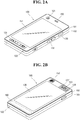
- FIG. 2A is a front perspective view of the mobile terminal according to an embodiment
- FIG. 2B is a rear perspective view of the mobile terminal according to an embodiment
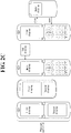
- FIGS. 2C and 2D illustrate forms of the mobile terminal and display screens according to various embodiments
- FIG. 3 is a view for explaining a proximity depth of a proximity sensor
- FIG. 4 is a block diagram showing a short range communication module of a mobile terminal according to an embodiment
- FIG. 5 is a diagram showing a system environment including a mobile terminal according to an embodiment
- FIG. 6 illustrates an example in which a mobile terminal according to an embodiment forms a communication link with another electronic device
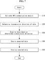
- FIG. 7 is a flowchart showing operation of the mobile terminal (of FIG. 1 );
- FIG. 8 is a message flow diagram between another terminal and the mobile terminal (of FIG. 1 );
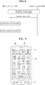
- FIG. 9 is a diagram showing near field communication (NFC) activation of the mobile terminal.
- NFC near field communication
- FIGS. 10 to 12 are diagrams showing a process of determining a data transmission direction of the mobile terminal
- FIGS. 13 and 14 are diagrams showing an example of determining a data transmission direction of the mobile terminal
- FIGS. 15 and 16 are diagrams showing an example of determining a data transmission direction of the mobile terminal
- FIG. 17 is a diagram showing an example of determining a data transmission direction of the mobile terminal.
- FIGS. 18 to 22 are diagrams of a process of coupling and displaying data of the mobile terminal
- FIGS. 23 to 25 are diagrams showing an example of coupling and displaying data of the mobile terminal
- FIGS. 26 and 27 are diagrams showing an example of coupling and displaying data of the mobile terminal
- FIG. 28 is a diagram of an example of coupling and displaying data of the mobile terminal.
- FIG. 29 is a diagram of an example of coupling and displaying data of the mobile terminal.
- FIGS. 30 to 32 are diagrams of an example of coupling and displaying data of the mobile terminal
- FIGS. 33 and 34 are diagrams of an example of coupling and displaying data of the mobile terminal
- FIGS. 35 to 38 are diagrams of a method of coupling data of the mobile terminal
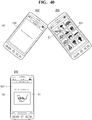
- FIGS. 39 and 40 are diagrams of an example of coupling and displaying data of the mobile terminal of FIG. 7 ;
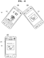
- FIG. 41 is a diagram showing transmitting data of the mobile terminal.
- FIGS. 42 and 43 are diagrams showing a limitation of transmitting data of the mobile terminal.
- a mobile terminal may be described below with reference to the accompanying drawings.
- suffixes "module” and “unit” may be given to components of the mobile terminal in consideration of only facilitation of description and do not have meanings or functions discriminated from each other.
- the mobile terminal may include a cellular phone, a smart phone, a laptop computer, a digital broadcasting terminal, personal digital assistants (PDA), a portable multimedia player (PMP), a navigation system and/or so on.
- PDA personal digital assistants
- PMP portable multimedia player
- FIG. 1 is a block diagram of a mobile terminal according to an embodiment. Other embodiments, configurations and arrangements may also be provided.
- the mobile terminal 100 may include a wireless communication unit 110 (or radio communication unit), an audio/video (A/V) input unit 120, a user input unit 130, a sensing unit 140, an output unit 150, a memory 160, an interface 170, a controller 180, and a power supply 190.
- the components shown in FIG. 1 may be essential parts and/or a number of components included in the mobile terminal 100 may vary. Components of the mobile terminal 100 may now be described.
- the wireless communication unit 110 may include at least one module that enables radio communication between the mobile terminal 100 and a radio communication system or between the mobile terminal 100 and a network in which the mobile terminal 100 is located.
- the wireless communication unit 110 may include a broadcasting receiving module 111, a mobile communication module 112, a wireless Internet module 113, a short range communication module 114 (or local area communication module), and a location information module 115 (or position information module).
- the broadcasting receiving module 111 may receive broadcasting signals and/or broadcasting related information from an external broadcasting management server through a broadcasting channel.
- the broadcasting channel may include a satellite channel and a terrestrial channel
- the broadcasting management server may be a server that generates and transmits broadcasting signals and/or broadcasting related information or a server that receives previously created broadcasting signals and/or broadcasting related information and transmits the broadcasting signals and/or broadcasting related information to a terminal.
- the broadcasting signals may include not only TV broadcasting signals, radio broadcasting signals, and data broadcasting signals but also signals in the form of a combination of a TV broadcasting signal and a radio broadcasting signal.
- the broadcasting related information may be information on a broadcasting channel, a broadcasting program or a broadcasting service provider, and may be provided even through a mobile communication network. In the latter case, the broadcasting related information may be received by the mobile communication module 112.
- the broadcasting related information may exist in various forms.
- the broadcasting related information may exist in the form of an electronic program guide (EPG) of a digital multimedia broadcasting (DMB) system or in the form of an electronic service guide (ESG) of a digital video broadcast-handheld (DVB-H) system.
- EPG electronic program guide
- ESG electronic service guide
- DMB digital multimedia broadcasting
- DVB-H digital video broadcast-handheld
- the broadcasting receiving module 111 may receive broadcasting signals using various broadcasting systems. More particularly, the broadcasting receiving module 111 may receive digital broadcasting signals using digital broadcasting systems such as a digital multimedia broadcasting-terrestrial (DMB-T) system, a digital multimedia broadcasting-satellite (DMB-S) system, a media forward link only (MediaFLO) system, a DVB-H and integrated services digital broadcast-terrestrial (ISDB-T) systems.
- DMB-T digital multimedia broadcasting-terrestrial
- DMB-S digital multimedia broadcasting-satellite
- MediaFLO media forward link only
- ISDB-T integrated services digital broadcast-terrestrial
- the broadcasting receiving module 111 may receive signals from broadcasting systems providing broadcasting signals other than the above-described digital broadcasting systems.
- the broadcasting signals and/or broadcasting related information received through the broadcasting receiving module 111 may be stored in the memory 160.
- the mobile communication module 112 may transmit/receive a radio signal to/from at least one of a base station, an external terminal and a server on a mobile communication network.
- the radio signal may include a voice call signal, a video telephony call signal or data in various forms according to transmission and reception of text/multimedia messages.
- the wireless Internet module 113 may correspond to a module for wireless Internet access and may be included in the mobile terminal 100 or may be externally attached to the mobile terminal 100.
- Wireless LAN WLAN or Wi-Fi
- Wibro wireless broadband
- Wimax world interoperability for microwave access
- HSDPA high speed downlink packet access
- the short range communication module 114 may correspond to a module for short range communication. Further, Bluetooth®, radio frequency identification (RFID), infrared data association (IrDA), ultra wideband (UWB) and/or ZigBee® may be used as a short range communication technique.
- RFID radio frequency identification
- IrDA infrared data association
- UWB ultra wideband
- ZigBee® ZigBee®
- the location information module 115 may confirm or obtain a location or a position of the mobile terminal 100.
- the location information module 115 may obtain position information by using a global navigation satellite system (GNSS).
- GNSS is a terminology describing a radio navigation satellite system that revolves around the earth and transmits reference signals to predetermined types of radio navigation receivers such that the radio navigation receivers can determine their positions on the earth's surface or near the earth's surface.
- the GNSS may include a global positioning system (GPS) of the United States, Galileo of Europe, a global orbiting navigational satellite system (GLONASS) of Russia, COMPASS of China, and a quasi-zenith satellite system (QZSS) of Japan, for example.
- GPS global positioning system
- Galileo Galileo of Europe
- GLONASS global orbiting navigational satellite system
- QZSS quasi-zenith satellite system
- a global positioning system (GPS) module is a representative example of the location information module 115.
- the GPS module may calculate information on distances between one point or object and at least three satellites and information on a time when distance information is measured and apply trigonometry to the obtained distance information to obtain three-dimensional position information on the point or object according to latitude, longitude and altitude at a predetermined time.
- a method of calculating position and time information using three satellites and correcting the calculated position and time information using another satellite may also be used. Additionally, the GPS module may continuously calculate a current position in real time and calculate velocity information using the location or position information.
- the A/V input unit 120 may input (or receive) an audio signal and/or a video signal.
- the A/V input unit 120 may include a camera 121 and a microphone 122.
- the camera 121 may process image frames of still images or moving images obtained by an image sensor in a video telephony mode or a photographing mode.
- the processed image frames may be displayed on a display 151, which may be a touch screen.
- the image frames processed by the camera 121 may be stored in the memory 160 or may be transmitted to an external device through the wireless communication unit 110.
- the mobile terminal 100 may also include at least two cameras 121.
- the microphone 122 may receive an external audio signal in a call mode, a recording mode and/or a speech recognition mode, and the microphone 122 may process the received audio signal into electric audio data. The audio data may then be converted into a form that can be transmitted to a mobile communication base station through the mobile communication module 112 and output in the call mode.
- the microphone 122 may employ various noise removal algorithms (or noise canceling algorithm) for removing or reducing noise generated when the external audio signal is received.
- the user input unit 130 may receive input data for controlling operation of the mobile terminal 100 from a user.
- the user input unit 130 may include a keypad, a dome switch, a touch pad (constant voltage/capacitance), a jog wheel, a jog switch and/or so on.
- the sensing unit 140 may sense a current state of the mobile terminal 100, such as an open/close state of the mobile terminal 100, a position of the mobile terminal 100, whether a user touches the mobile terminal 100, a direction of the mobile terminal 100, and acceleration/deceleration of the mobile terminal 100, and the sensing unit 140 may generate a sensing signal for controlling operation of the mobile terminal 100.
- the sensing unit 140 may sense whether the slide phone is opened or closed. Further, the sensing unit 140 may sense whether the power supply 190 supplies power and/or whether the interface 170 is connected to an external device.
- the sensing unit 140 may also include a proximity sensor 141. The sensing unit 140 may sense a motion of the mobile terminal 100.
- the output unit 150 may generate visual, auditory and/or tactile output, and the output unit 150 may include the display 151, an audio output module 152, an alarm 153 and a haptic module 154.
- the display 151 may display information processed by the mobile terminal 100.
- the display 151 may display a user interface (UI) and/or a graphic user interface (GUI) related to a telephone call when the mobile terminal 100 is in the call mode.
- the display 151 may also display a captured and/or received image, a UI or a GUI when the mobile terminal 100 is in the video telephony mode or the photographing mode.
- the display 151 may include at least one of a liquid crystal display, a thin film transistor liquid crystal display, an organic light-emitting diode display, a flexible display and/or a three-dimensional display.
- the display 151 may be of a transparent type or a light transmissive type. That is, the display 151 may include a transparent display.
- the transparent display may be a transparent liquid crystal display.
- a rear structure of the display 151 may also be of a light transmissive type. Accordingly, a user may see an object located behind the body (of the mobile terminal 100) through the transparent area of the body of the mobile terminal 100 that is occupied by the display 151.
- the mobile terminal 100 may also include at least two displays 151.
- the mobile terminal 100 may include a plurality of displays 151 that are arranged on a single face at a predetermined distance or integrated displays.
- the plurality of displays 151 may also be arranged on different sides.
- the display 151 and a sensor sensing touch form a layered structure that is referred to as a touch screen
- the display 151 may be used as an input device in addition to an output device.
- the touch sensor may be in the form of a touch film, a touch sheet, and/or a touch pad, for example.
- the touch sensor may convert a variation in pressure applied to a specific portion of the display 151 or a variation in capacitance generated at a specific portion of the display 151 into an electric input signal.
- the touch sensor may sense pressure of touch as well as position and area of the touch.
- a signal corresponding to the touch input may be transmitted to a touch controller.
- the touch controller may then process the signal and transmit data corresponding to the processed signal to the controller 180. Accordingly, the controller 180 may detect a touched portion of the display 151.
- the proximity sensor 141 (of the sensing unit 140) may be located in an internal region of the mobile terminal 100, surrounded by the touch screen, and/or near the touch screen.
- the proximity sensor 141 may sense an object approaching a predetermined sensing face or an object located near the proximity sensor 141 using an electromagnetic force or infrared rays without having mechanical contact.
- the proximity sensor 141 may have a lifetime longer than a contact sensor and may thus have a wide application in the mobile terminal 100.
- the proximity sensor 141 may include a transmission type photo-electric sensor, a direct reflection type photo-electric sensor, a mirror reflection type photo-electric sensor, a high-frequency oscillating proximity sensor, a capacitive proximity sensor, a magnetic proximity sensor, and/or an infrared proximity sensor.
- a capacitive touch screen may be constructed such that proximity of a pointer is detected through a variation in an electric field according to the proximity of the pointer.
- the touch screen (touch sensor) may be classified as a proximity sensor 141.
- an action of the pointer approaching the touch screen without actually touching the touch screen may be referred to as a proximity touch and an action of bringing the pointer into contact with the touch screen may be referred to as a contact touch.
- the proximity touch point of the pointer on the touch screen may correspond to a point of the touch screen at which the pointer is perpendicular to the touch screen.
- the proximity sensor 141 may sense the proximity touch and a proximity touch pattern (e.g., a proximity touch distance, a proximity touch direction, a proximity touch velocity, a proximity touch time, a proximity touch position, a proximity touch moving state, etc.). Information corresponding to the sensed proximity touch action and proximity touch pattern may then be displayed on the touch screen.
- a proximity touch pattern e.g., a proximity touch distance, a proximity touch direction, a proximity touch velocity, a proximity touch time, a proximity touch position, a proximity touch moving state, etc.
- the audio output module 152 may output audio data received from the wireless communication unit 110 or stored in the memory 160 in a call signal receiving mode, a telephone call mode or a recording mode, a speech recognition mode and a broadcasting receiving mode.
- the audio output module 152 may output audio signals related to functions, such as a call signal incoming tone and a message incoming tone, performed in the mobile terminal 100.
- the audio output module 152 may include a receiver, a speaker, a buzzer, and/or the like.
- the audio output module 152 may output sounds through an earphone jack. The user may hear the sounds by connecting an earphone to the earphone jack.
- the alarm 153 may output a signal for indicating generation of an event of the mobile terminal 100. For example, an alarm may be generated when receiving a call signal, receiving a message, inputting a key signal, and/or inputting a touch.
- the alarm 153 may also output signals in forms different from video signals or audio signals, for example, a signal for indicating generation of an event through vibration.
- the video signals and/or the audio signals may also be output through the display 151 or the audio output module 152.
- the haptic module 154 may generate various haptic effects that the user can feel.
- One example of the haptic effects is vibration.
- An intensity and/or pattern of vibration generated by the haptic module 154 may also be controlled. For example, different vibrations may be combined and output or may be sequentially output.
- the haptic module 154 may generate a variety of haptic effects including an effect of stimulus according to an arrangement of pins vertically moving against a contact skin surface, an effect of stimulus according to a jet force or sucking force of air through a jet hole or a sucking hole, an effect of stimulus of rubbing the skin, an effect of stimulus according to contact of an electrode, an effect of stimulus using an electrostatic force, and an effect according to a reproduction of cold and warmth using an element capable of absorbing or radiating heat in addition to vibrations.
- the haptic module 154 may not only transmit haptic effects through direct contact but may also allow the user to feel haptic effects through a kinesthetic sense of the user's fingers or arms.
- the mobile terminal 100 may also include a plurality of haptic modules 154.
- the memory 160 may store a program for operations of the controller 180 and/or temporarily store input/output data such as a phone book, messages, still images, and/or moving images.
- the memory 160 may also store data about vibrations and sounds in various patterns that are output from when a touch input is applied to the touch screen.
- the memory 160 may include at least a flash memory, a hard disk type memory, a multimedia card micro type memory, a card type memory, such as SD or XD memory, a random access memory (RAM), a static RAM (SRAM), a read-only memory (ROM), an electrically erasable programmable ROM (EEPROM), a programmable ROM (PROM) magnetic memory, a magnetic disk and/or an optical disk.
- the mobile terminal 100 may also operate in relation to a web storage that performs a storing function of the memory 160 on the Internet.
- the interface 170 may serve as a path to external devices connected to the mobile terminal 100.
- the interface 170 may receive data from the external devices or power and transmit the data or power to internal components of the mobile terminal 100 or transmit data of the mobile terminal 100 to the external devices.
- the interface 170 may include a wired/wireless headset port, an external charger port, a wired/wireless data port, a memory card port, a port for connecting a device having a user identification module, an audio I/O port, a video I/O port, and/or an earphone port.
- the interface 170 may also interface with a user identification module that is a chip that stores information for authenticating authority to use the mobile terminal 100.
- the user identification module may be a user identify module (UIM), a subscriber identify module (SIM) and/or a universal subscriber identify module (USIM).
- An identification device (including the user identification module) may also be manufactured in the form of a smart card. Accordingly, the identification device may be connected to the mobile terminal 100 through a port of the interface 170.
- the interface 170 may also be a path through which power from an external cradle is provided to the mobile terminal 100 when the mobile terminal 100 is connected to the external cradle or a path through which various command signals input by the user through the cradle are transmitted to the mobile terminal 100.
- the various command signals or power input from the cradle may be used as signals for confirming whether the mobile terminal 100 is correctly set in the cradle.
- the controller 180 may control overall operations of the mobile terminal 100.
- the controller 180 may perform control and processing for voice communication, data communication and/or video telephony.
- the controller 180 may also include a multimedia module 181 for playing multimedia.
- the multimedia module 181 may be included in the controller 180 or may be separated from the controller 180.
- the controller 180 may perform a pattern recognition process capable of recognizing handwriting input or picture-drawing input applied to the touch screen as characters or images.
- the power supply 190 may receive external power and internal power and provide power required for operations of the components of the mobile terminal 100 under control of the controller 180.
- embodiments may be implemented using at least one of application specific integrated circuits (ASICs), digital signal processors (DSPs), digital signal processing devices (DSPDs), programmable logic devices (PLDs), field programmable gate arrays (FPGAs), processors, controllers, micro-controllers, microprocessors, and/or electrical units for executing functions.
- ASICs application specific integrated circuits
- DSPs digital signal processors
- DSPDs digital signal processing devices
- PLDs programmable logic devices
- FPGAs field programmable gate arrays
- processors controllers, micro-controllers, microprocessors, and/or electrical units for executing functions.
- controller 180 may be implemented by the controller 180.
- embodiments such as procedures or functions may be implemented with a separate software module that executes at least one function or operation.
- Software codes may be implemented according to a software application written in an appropriate software language. The software codes may be stored in the memory 160 and executed by the controller 180.
- FIG. 2A is a front perspective view of a mobile terminal (or a handheld terminal) according to an embodiment.
- the mobile terminal 100 may be a bar type terminal body. However, embodiments are not limited to a bar type terminal and may be applied to terminals of various types including slide type, folder type, swing type and/or swivel type terminals having at least two bodies that are relatively movably combined.
- the terminal body may include a case (a casing, a housing, a cover, etc.) that forms an exterior of the mobile terminal 100.
- the case may be divided into a front case 101 and a rear case 102.
- Various electronic components may be arranged in the space formed between the front case 101 and the rear case 102.
- At least one middle case may be additionally provided between the front case 101 and the rear case 102.
- the cases may be formed of plastics through injection molding or made of a metal material such as stainless steel (STS) or titanium (Ti).
- STS stainless steel
- Ti titanium
- the display 151, the audio output unit 152, the camera 121, the user input unit 130/131 and 132, the microphone 122 and the interface 170 may be arranged (or provided) in the terminal body, and more specifically may be arranged (or provided) in the front case 101.
- the display 151 may occupy most of the main face of the front case 101.
- the audio output unit 152 and the camera 121 may be arranged in a region in proximity to one of both ends of the display 151 and the user input unit 131, and the microphone 122 may be located in a region in proximity to another end of the display 151.
- the user input unit 132 and the interface 170 may be arranged (or provided) on sides of the front case 101 and the rear case 102.
- the user input unit 130 may receive commands for controlling operation of the mobile terminal 100, and may include a plurality of operating units 131 and 132.
- the operating units 131 and 132 may be referred to as manipulating portions and may employ any tactile manner in which a user operates the operating units 131 and 132 while having tactile feeling.
- the first and second operating units 131 and 132 may receive various inputs.
- the first operating unit 131 may receive commands such as start, end and scroll and the second operating unit 132 may receive commands such as control of a volume of sound output from the audio output unit 152 or conversion of the display 151 to a touch recognition mode.
- FIG. 2B is a rear perspective view of the mobile terminal (shown in FIG. 2A ) according to an embodiment.
- a camera 121' may be additionally attached to the rear side of the terminal body (i.e., the rear case 102).
- the camera 121' may have a photographing direction opposite to that of the camera 121 (shown in FIG. 2A ) and may have pixels different from those of the camera 121 (shown in FIG. 2A ).
- the camera 121 has low pixels such that the camera 121 may capture an image of a face of a user and transmit the image to a receiving part in case of video telephony while the camera 121' has high pixels because the camera 121' captures an image of a general object and does not immediately transmit the image in many cases.
- the cameras 121 and 121' may be attached (or provided) to the terminal body such that the cameras 121 and 121' may rotate or pop-up.
- a flash bulb 123 and a mirror 124 may be additionally provided in proximity to the camera 121'.
- the flash bulb 123 may light an object when the camera 121' takes a picture of the object.
- the mirror 124 may be used for the user to look at his/her face in the mirror when the user wants to self-photograph himself/herself using the camera 121'.
- An audio output unit 152' may be additionally provided on the rear side of the terminal body.
- the audio output unit 152' may achieve a stereo function with the audio output unit 152 (shown in FIG. 2A ) and may be used for a speaker phone mode when the terminal is used for a telephone call.
- a broadcasting signal receiving antenna may be additionally attached (or provided) to the side of the terminal body in addition to an antenna for telephone calls.
- the antenna constructing a part of the broadcasting receiving module 111 may be set in the terminal body such that the antenna may be pulled out of the terminal body.
- the power supply 190 for providing power to the mobile terminal 100 may be set in the terminal body.
- the power supply 190 may be included in the terminal body or may be detachably attached to the terminal body.
- a touch pad 135 for sensing touch may be attached to the rear case 102.
- the touch pad 135 may be of a light transmission type, such as the display 151.
- the display 151 outputs visual information through both sides thereof, the visual information may be recognized (or determined) by the touch pad 135.
- the information output through both sides of the display 151 may be controlled by the touch pad 135.
- a display may be additionally attached (or provided) to the touch pad 135 such that a touch screen may be arranged (or provided) even in the rear case 102.
- the touch pad 135 may operate in connection with the display 151 of the front case 101.
- the touch pad 135 may be located in parallel with the display 151 behind the display 151.
- the touch panel 135 may be identical to or smaller than the display 151 in size.
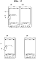
- FIGs. 2C and 2D illustrate the mobile terminal 100 and the display 151 according to various embodiments.
- the display 151 may include a first display and a second display that are physically separated from each other.
- the first display or main display
- the second display or sub display
- the sub display may be separated from the mobile terminal and may be detachably combined with the mobile terminal body through an interface to display data from the mobile terminal 100.
- the display 151 may include first and second displays that may be logically separated from each other in a display panel, as shown in FIG. 2D .
- FIG. 3 is a view for explaining a proximity depth of a proximity sensor.
- the proximity sensor located inside or near the touch screen may sense the approach of the pointer, and may output a proximity signal.
- the proximity sensor may be constructed such that the proximity sensor outputs a proximity signal according to a distance between the pointer approaching the touch screen and the touch screen (referred to as "proximity depth").
- the distance in which the proximity signal is output when the pointer approaches the touch screen may be referred to as a detection distance.
- the proximity depth may be determined by using a plurality of proximity sensors having different detection distances and by comparing proximity signals respectively output from the proximity sensors.
- FIG. 3 shows a section of the touch screen in which proximity sensors capable of sensing three proximity depths may be provided. Proximity sensors capable of sensing less than three or more than four proximity depths may be provided in the touch screen.
- the pointer when the pointer completely contacts the touch screen (D0), it may be recognized as contact touch.
- the pointer When the pointer is located within a distance D1 from the touch screen, it may be recognized as a proximity touch of a first proximity depth.
- the pointer When the pointer is located in a range between the distance D1 and a distance D2 from the touch screen, it may be recognized as a proximity touch of a second proximity depth.
- the pointer When the pointer is located in a range between the distance D2 and a distance D3 from the touch screen, it may be recognized as a proximity touch of a third proximity depth.
- the pointer When the pointer is located greater than the distance D3 from the touch screen, it may be recognized as cancellation of the proximity touch.
- the controller 180 may recognize the proximity touch as various input signals according to proximity distance and proximity position of the pointer with respect to the touch screen, and the controller 810 may perform various operation controls according to the input signals.
- FIG. 4 is a block diagram showing a short range communication module 114 of the mobile terminal 100 according to an embodiment.
- the short range communication module 114 may include a near field communication (NFC) module 117, a Bluetooth communication module 118 and so on.
- NFC near field communication
- the NFC communication module 117 may perform data communication with devices positioned at a distance within 10 cm (preferably within 4 cm) using very short-range contactless data transfer technology related to radio frequency identification (RFID).
- An electronic device that adapts NFC technology may communicate with another electronic device that adapts NFC technology through at least one of a reader mode, a card emulation mode, and/or a pier to pier mode, for example.
- the NFC communication module 117 may be described with reference to FIG. 5 .
- the Bluetooth communication module 118 may perform data communication with devices within a radius 10 to 100 m using Bluetooth, which is one type of short range wireless communication formats.
- Bluetooth is short range wireless networking technology that was developed by a Bluetooth special interest group (SIG).
- the block diagram shown in FIG. 4 is an example of the short range communication module 114 according to the present embodiment, and elements of the short range communication module 114 may not be essential elements.
- the short range communication module 114 may include elements more than or fewer than shown in FIG. 4 .
- FIG. 5 is a diagram illustrating a system environment that includes the mobile terminal 100. As shown in FIG. 5 , the system environment may be formed with the mobile terminal 100 and one or more other electronic devices 200 and 300 that may form an NFC link with the mobile terminal 100. The electronic devices 200 and 300 may be mobile terminals.
- the system environment may include elements fewer than or more than shown in FIG. 5 .
- FIG. 5 in order to describe a communication link forming a characteristic of the mobile terminal 100, only certain elements for forming a communication link may be shown.
- the system environment may be formed with mobile terminals, although electronic devices described herein may be a random electronic device for supporting NFC communication. That is, the electronic devices 200, and 300 may be a mobile terminal such as a mobile phone, a smart phone, and/or a tablet PC for supporting NFC communication, and/or may be an electronic device such as a printer, a television, a digital television, a computer, and/or an audio device. An electronic device having a NFC communication function may be referred to as an NFC electronic device.
- the mobile terminal 100 may form an NFC link with the other electronic devices 200 and 300 based on NFC communication technology, which is a type of short range communication technology, although a range is not limited thereto.
- NFC communication technology which is a type of short range communication technology, although a range is not limited thereto.
- the mobile terminal 100 may form a wireless communication link with the other electronic devices 200 and 300 using short range wireless communication technology other than NFC communication technology.
- the mobile terminal 100 may include the controller 180, the NFC communication module 117, the Bluetooth communication module 118, and/or a Wi-Fi communication module 119.
- the controller 180 may control elements within the mobile terminal 100.
- the NFC communication module 117 may enable the mobile terminal 100 to form an NFC link with other electronic devices 200 and 300 that support NFC communication.
- the NFC communication module 117 may indicate an NFC forum device.
- the NFC communication module 117 may be referred to as a short range communication means.
- the NFC communication module 117 may form an NFC link through tagging with an NFC communication module of the other electronic devices 200 and 300 that are within an NFC communication range.
- the NFC communication module 117 may communicate in various modes with the NFC communication module of the other electronic devices 200 and 300.
- the various modes may include a card emulation mode, a reader mode, and/or a peer to peer mode, for example.
- the NFC communication module 117 When the NFC communication module 117 operates in the card emulation mode, the NFC communication module 117 (of the mobile terminal 100) may function as a card (i.e., a tag). In this example, the NFC communication module of the other electronic devices 200 and 300 may operate in a reader mode and may acquire data from the NFC communication module 117 of the mobile terminal 100.
- the NFC communication module 117 When the NFC communication module 117 operates in the reader mode, the NFC communication module 117 (of the mobile terminal 100) may function as a reader. In this example, the NFC communication module 117 of the mobile terminal 100 may acquire data from the NFC communication module of the other electronic devices 200 and 300 operating in an emulation mode.
- the NFC communication module 117 When the NFC communication module 117 operates in the peer to peer mode, the NFC communication module 117 (of the mobile terminal 100) and the NFC communication module of the other electronic devices 200 and 300 may exchange data.
- a mode of the NFC communication module 117 may be determined according to a predetermined reference. For example, a mode of the NFC communication module 117 may be set based on a user input, or a predetermined algorithm.
- the mobile terminal 100 may form an NFC link through the NFC communication module 117 with the other electronic devices 200 and 300, and then may form a communication link, different from the NFC link, with the other electronic devices 200 and 300 through the Bluetooth communication module 118 and/or the Wi-Fi communication module 119. Therefore, even if the NFC communication link is disconnected, the mobile terminal 100 may continue to perform data communication with the other electronic devices 200 and 300 through the Bluetooth communication module 118 and/or the Wi-Fi communication module 119.
- handover a series of processes of forming another communication link in order to enable the mobile terminal 100 to continue to communicate with the other electronic devices 200 and 300 using other wireless communication technology may be referred to as handover.
- a handover may be performed from an NFC communication link to a Bluetooth communication link or a Wi-Fi communication link, although a range is not limited thereto.
- the mobile terminal 100 may perform a handover to various communication links, such as an RFID communication link and a wireless gigabit (WiGig) communication link.
- WiGig wireless gigabit
- the other electronic devices 200 and 300 may include elements corresponding to the mobile terminal 100.
- the other electronic devices 200 and 300 may include a controller, an NFC communication module, a Bluetooth communication module, and/or a Wi-Fi communication module.
- the handover may indicate that the mobile terminal 100 performs data communication by forming an NFC link and then forming another communication link with the other electronic devices 200 and 300, and a user may easily form an NFC link through NFC tagging between the mobile terminal 100 and the other electronic devices 200 and 300 and change a communication means to an alternate communication link appropriate for transmitting a longer distance and/or a greater amount of data than the NFC link.
- a handover process of the mobile terminal 100 may be described with reference to the drawings. For ease of description, a handover process may be described with reference to the system environment shown in FIG. 5 . Embodiments are not limited to a specific environment or a specific device.
- FIG. 6 illustrates an example in which the mobile terminal 100 forms a communication link with the another electronic device 200.
- a process of forming a communication link may be described with reference to the drawings.
- the mobile terminal 100 may transmit a handover request message to the another electronic device 200 (S110). Before operation S110, the mobile terminal 100 and the another electronic device 200 may form a communication link through a first communication means. As one example, the mobile terminal 100 may form an NFC link through tagging to an NFC communication module 220 included in the another electronic device 200.
- the mobile terminal 100 may transmit a message (e.g. a handover request message) for a handover request to the another electronic device 200 through the NFC link.
- a message e.g. a handover request message
- the mobile terminal 100 and the another electronic device 200 may start a protocol for forming another communication link through the NFC link formed between the mobile terminal 100 and the another electronic device 200.
- the mobile terminal 100 may be a handover requester, and the another electronic device 200 may be a handover selector.
- the handover requester may be a device for starting a handover protocol by transmitting a handover request message to another NFC electronic device.
- the handover selector may be an NFC device for writing and responding with a handover selection message as a response to the received handover request message.
- the handover requester i.e., a handover request device
- the handover selector i.e., a handover selection device
- the handover request message may include information about another communication module that is supported by the mobile terminal 100.
- the handover request message may include information about Bluetooth and/or Wi-Fi that are supported by the mobile terminal 100.
- a priority order may be set to communication technology used for handover and that is supported by the mobile terminal 100.
- the handover request message may have information about a communication module for supporting communication technology having a high priority order at a front thereof and that has information about a communication module for supporting communication technology having a low priority order at a rear thereof.
- the handover request message it may be determined that information about a Wi-Fi communication module has a priority order higher than information about a Bluetooth communication module.
- Another electronic device 200 having received the handover request message may transmit a response to the handover request message to the mobile terminal 100 (S120).
- the another electronic device 200 may generate a handover selection message as an example of a response to the handover request message through the NFC link, and may transmit the generated handover selection message to the mobile terminal 100.
- the another electronic device 200 may determine a communication module included in the mobile terminal 100 by analyzing the handover request message and based on the determination may provide information about a communication module included in the another electronic device 200 to the mobile terminal 100. That is, information about a communication module included in the handover selection message may include information about a communication module included in the another electronic device 200 from among communication modules included in the mobile terminal 100.
- a controller 210 of the another electronic device 200 may determine that the Bluetooth communication module 118 and the Wi-Fi communication module 119 are included in the mobile terminal 100 by analyzing the received handover request message and transmitting a handover selection message including information about a Bluetooth communication module 230 and a Wi-Fi communication module 240 included in the another electronic device 200 to the mobile terminal 100.
- the controller 180 of the mobile terminal 100 may determine that the Bluetooth communication module 230 and the Wi-Fi communication module 240 are included in the another electronic device 200 by analyzing the handover selection message and may receive (or acquire) information thereof.
- the mobile terminal 100 may form a communication link with communication modules included in the another electronic device 200 based on the received information, and the mobile terminal 100 may perform data communication with the another electronic device 200 through the formed communication link (S120).
- the controller 180 may perform a Bluetooth pairing with the another electronic device 200.
- the mobile terminal 100 may continue to perform communication according to a Bluetooth protocol by converting a communication link with the another electronic device 200 from the NFC communication link to the Bluetooth communication link.
- the NFC communication link to the Bluetooth communication link may be performed, and data may be exchanged with a transmission speed faster than the NFC link, even if the mobile terminal 100 and the another electronic device 200 are no longer positioned within an NFC communication range (shown in FIG.6 ).
- the mobile terminal 100 when the mobile terminal 100 is a smart phone, the user may bring the smart phone to a periphery of the another electronic device 200 and may perform tagging with the another electronic device 200, and thus an NFC link may be formed, and by performing a handover protocol, a communication means may be changed to the Bluetooth communication link. Therefore, even if the user takes a smart phone out of an NFC communication range, the smart phone and the another electronic device 200 may continue to perform data communication using the Bluetooth communication link.
- the controller 180 (of the mobile terminal 100) may perform a process of forming a Wi-Fi communication link with the another electronic device 200 in order to change the NFC communication link with the another electronic device 200 to the Wi-Fi communication link and perform data communication with the another electronic device 200 through the formed Wi-Fi communication link. Therefore, the mobile terminal 100 may perform data communication with the another electronic device 200 even outside a NFC communication range with a data transmission and reception speed faster than the NFC communication link.
- the controller 180 when a plurality of communication links exist that may be changed from the NFC communication link, the controller 180 (of the mobile terminal 100) may perform handover for only a communication link selected from the plurality of communication links and may perform handover to the plurality of communication links. Further, when a communication link for performing a handover is selected from a plurality of communication links, the controller 180 may select a communication link according to a predetermined priority order.
- FIG. 7 is a flowchart of an operation of the mobile terminal.
- the controller 180 may activate the NFC communication module 117 (S10).
- the NFC communication module 117 may be selectively activated or inactivated by a user's selection and/or a control operation of the controller 180. For example, in a situation in which a NFC communication is not used, because electricity is not supplied to the NFC communication module 117, consumption of a battery may be reduced. Therefore, when the NFC communication module 117 is inactivated, in order to perform communication of an NFC method, the NFC communication module 117 may be activated.
- the controller 180 may determine a transmission direction of data (S20).
- Data may be transmitted from the mobile terminal 100 to another terminal through the NFC communication module, or data may be transmitted from another terminal to the mobile terminal 100 through the NFC communication module 117.
- a transmission direction of data may be determined based on the user's manipulation form of a main body of the mobile terminal 100. For example, a transmission direction of data may be determined by an action of colliding the mobile terminal 100 with another terminal. That is, when performing an action of colliding the mobile terminal 100 with another terminal in a stationary state at a specific position by moving the mobile terminal 100, data of the mobile terminal 100 may be transmitted to the another terminal.
- a transmission direction of data may be determined based on a form advancing into an area in which a NFC communication is available. For example, when the mobile terminal 100 enters into an NFC area of another terminal waiting for NFC communication, data of the mobile terminal 100 may be transmitted to another terminal.
- a transmission direction of data may be determined based on a form in which the user performs a touch. For example, when a drag touch action is performed from one direction to another direction on the display 151, data of the mobile terminal 100 may be transmitted to another terminal in an advancing direction of a drag touch action.
- the controller 180 may receive (or acquire) data based on the determined transmission direction (S30).
- Data may be information stored in the memory 160.
- data may be a text, an image, and/or a moving picture stored in the memory 160.
- a text may be transmitted from the another terminal to the mobile terminal 100. That is, the mobile terminal 100 may receive (or acquire) data from the other terminal based on a determined direction.
- Operation S40 of coupling the acquired (or received) data and operation S50 of displaying the coupled data may be performed.
- the controller 180 may couple the received data (S40).
- the mobile terminal 100 may couple the received information to previously stored information in the memory 160.
- the mobile terminal 100 may couple first information received from a first terminal and second information received from a second terminal.
- the controller 180 may generate data of a new form by coupling the received data. Therefore, a cooperation of generating one data as a plurality of persons separately operate in a plurality of electronic devices may be performed.
- the controller 180 may control the display 151 to display the coupled data (S50).
- FIG. 8 is a message flow diagram between another terminal and the mobile terminal (of FIG. 1 ).
- the mobile terminal 100 and the another terminal 200 may determine a transmission direction of data (S20).
- a transmission direction of data may be determined by a control operation performed between the mobile terminal 100 and the another terminal 200. For example, as described above, a transmission direction of data may be determined based on an action of colliding the mobile terminal 100 with the another terminal 200, moving the mobile terminal 100 into an NFC communication area of the another terminal 200, and/or performing a specific touch action in the mobile terminal 100.
- the another terminal 200 may transmit data to the mobile terminal 100 (S31).
- Data may be transmitted through communication using a NFC method. Furthermore, data may be transmitted by handover from communication using a NFC method to communication using a Wi-Fi method.
- the mobile terminal 100 may couple the acquired (or received) data (S40), and the mobile terminal 100 may display the coupled data (S50).
- FIG. 9 is a diagram showing an NFC activation of the mobile terminal.
- the controller 180 may control the display 151 to display a soft key SK for activating a NFC communication.
- the soft key SK may be selectively displayed in the display 151. For example, when a user performs a touch action of dragging an indicator area IA of the display 151 in a lateral direction and/or in a vertical direction, the soft key SK may be displayed. When the user again performs the same touch action, the displayed soft key SK may disappear.
- the soft key SK When activation of a specific function is toggled, the soft key SK may be selected. For example, when the soft key SK is touched one time, the NFC communication module 117 may be activated, and when the soft key SK is touched again, the NFC communication module 117 may be inactivated.
- the soft key SK may include a button corresponding to other functions in which the user frequently uses in addition to a button related to the NFC communication module 117.
- NFC communication may be activated through a key button 131 provided in a surface of the mobile terminal 100.
- the controller 180 may activate or inactivate the NFC communication module 117.
- FIGS. 10 to 12 are diagrams of a process of determining a data transmission direction of the mobile terminal.
- the mobile terminal 100 may determine a transmission direction of data based on a colliding action of the mobile terminal 100 and the another terminal 200.
- the mobile terminal 100 may be in a stationary state at a specific position, and the another terminal 200 may move toward the mobile terminal 100.
- Movement of the mobile terminal 100 may be detected by an acceleration sensor, a terrestrial magnetism sensor, and/or a magnetic sensor included in the sensing unit 140.
- the sensing unit 140 may detect a change according to movement of the mobile terminal 100. That is, a stationary state and a moving state of the mobile terminal 100 may be detected by the sensing unit 140.
- a description in which the sensing unit 140 detects movement of the mobile terminal 100 may be applied to the another terminal 200. For example, as shown in FIG. 10A , when the mobile terminal 100 stops and the another terminal 200 moves, controllers of the mobile terminal 100 and the another terminal 200 may determine, based on a detection value of the sensing unit 140, that a corresponding device is moving or stops.
- the moving another terminal 200 may collide with the mobile terminal 100 that is stopped at a specific position.
- controllers of the two devices may determine which terminal collides with which terminal based on a detection result of the sensing unit 140.
- the mobile terminal 100 stops and the another terminal 200 may collide.
- the user may have an intention to move data from the another terminal 200 to the mobile terminal 100.
- the user may collide the another terminal 200 and the mobile terminal 100 by moving the mobile terminal 100 to the stationary another terminal 200.
- the user may have an intention to move data from the mobile terminal 100 to the another terminal 200.
- the user may collide the mobile terminal 100 and the another terminal 200 by moving both the mobile terminal 100 and the another terminal 200.
- the user may have an intention to exchange data of the two terminals 100 and 200.
- FIGs. 13 and 14 are diagrams of an example of determining a data transmission direction of the mobile terminal.
- a transmission direction of data may be determined according to whether the mobile terminal 100 enters an available area of NFC communication.
- an available field of a NFC communication may be formed within a predetermined radius of the mobile terminal 100.
- the user may move the another terminal 200 into an area that may perform a NFC communication with the mobile terminal 100.
- the another terminal 200 may move into an area in which the mobile terminal 100 may perform a NFC communication.
- the user may have an intention to transmit data from the another terminal 200 to the mobile terminal 100.
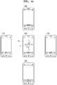
- FIGs. 15 and 16 are diagrams of an example of determining a data transmission direction of the mobile terminal.
- the mobile terminal 100 may determine a data transmission direction based on a touch action.
- the user may perform a touch action of touching the display 151 with a finger F and dragging in a direction of the another terminal 200.
- the mobile terminal 100 and the another terminal 200 may be adjacently positioned or positioned a predetermined distance away from each other.
- Data may move in a direction of a touch action of the user.
- data may be transmitted from the mobile terminal 100 to the another terminal 200.
- other terminals 201 to 204 may be positioned at a periphery of the mobile terminal 100.
- the user may perform a drag touch action in a specific direction in the display 151 with a finger F.
- Data of the mobile terminal 100 may be transmitted to at least one of the other terminals 201 to 204 based on a direction of a drag touch action.
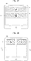
- FIG. 17 is a diagram of an example of determining a data transmission direction of the mobile terminal.
- the mobile terminal 100 may determine a transmission direction of data based on a selection using a first pop-up window P1.
- the first pop-up window P1 may display a menu for selecting whether the mobile terminal 100 is to operate as a transmitting side, operate as a receiving side, and/or perform a data exchange operation.
- the user may determine an operation of the mobile terminal 100 by selecting a specific menu.
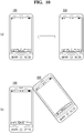
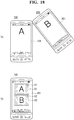
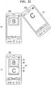
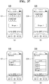
- FIGS. 18 to 22 are diagrams of a process of coupling and displaying data of the mobile terminal.
- the mobile terminal 100 may transmit and couple data based on a determined data transmission direction.
- the user may enable the another terminal 200 to collide with the mobile terminal 100. That is, the user may have an intention to transmit data from the another terminal 200 to the mobile terminal 100.
- Contents to be transmitted or coupled may be stored in the mobile terminal 100 and the another terminal 200.
- contents of the mobile terminal 100 may be represented as A and contents of the another terminal 200 may be represented as B.
- data of the another terminal 200 may be transmitted to the mobile terminal 100.
- the controller 180 may control the display 151 to display contents B, which are data received from the another terminal 200.
- the display 151 may be divided into a first area D1 representing contents A stored in the mobile terminal 100 and a second area D2 representing received contents B.
- First and second delete buttons C1 and C2 may be positioned at the first and second areas D1 and D2, respectively. A detailed function of the first and second delete buttons C1 and C2 may be described in a related portion.
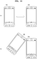
- the user may perform a touch action of touching the first area D1 and dragging to the lower side of the second area D2.
- the order of contents displayed in the display 151 by a drag touch action of the user may change. That is, as the user performs an appropriate drag touch action, the order of contents displayed in the display 151 may change.
- the user may perform an action of touching the first delete button C1 of the first area D1 with a finger F.
- the display of the first area D1 may disappear.
- the user may enable another terminal 300 to collide with the mobile terminal 100.
- contents C of the another terminal 300 may be transmitted to the mobile terminal 100 based on the collision.
- the transmitted contents C may be displayed in the third area D3.
- the user may perform an action of touching a point other than second and third areas D2 and D3. That is, in the display 151, an action of touching a point other than the second and third areas D2 and D3 may be performed.
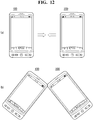
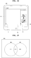
- FIGs. 23 to 25 are diagrams of an example of coupling and displaying data of the mobile terminal.
- contents of the another terminal 200 may be transmitted to the mobile terminal 100.
- the controller 180 may compare contents stored in the mobile terminal 100 and the received contents and may display different portions. For example, a form of first and second texts DT1 and DT2 may have been stored in the mobile terminal 100, but a form of first and second other texts DP1 and DP2 may be received (or acquired) from the another terminal 200.
- the controller 180 differently displays colors of the first and second texts DT1 and DT2 and the first and second other texts DP1 and DP2, the user may easily recognize the difference thereof.
- the user may select a desired portion from the first text DT1 and the first other text DP1 using a finger F.
- the first other text DP1 may disappear and only the first text DT1 may be displayed in the display 151.
- the user may select the second other text DP2 with the finger F.
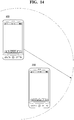
- FIGs. 26 and 27 are diagrams of an example of coupling and displaying data of the mobile terminal.
- the mobile terminal 100 may receive (or acquire) and display contents from a plurality of other terminals 200 and 300.
- the mobile terminal 100 may be a tablet PC. That is, the mobile terminal 100 may have the display 151 that is wider than a common display. Contents A and B may be stored in the first and second other terminals 200 and 300, respectively. The mobile terminal 100 may receive substantially simultaneously data from the first and second other terminals 200 and 300.
- the mobile terminal 100 may display substantially simultaneously received contents in the display 151.
- FIG. 28 is a diagram of an example of coupling and displaying data of the mobile terminal.
- the mobile terminal 100 may display received (or acquired) contents with various methods. That is, the display 151 may be vertically divided, and contents received (or acquired) from the first another terminal 200 may be displayed in a first area D1 of a first display area PG1, and contents received (or acquired) from the second other terminal 300 may be displayed in a second area D2 of a second display area PG2.
- FIG. 29 is a diagram of an example of coupling and displaying data of the mobile terminal.
- the mobile terminal 100 may display contents of different forms that are received from a plurality of other terminals 200 and 300.
- the first another terminal 200 may include contents of a text TX form.
- the second another terminal 300 may include contents of an image PH form.
- the mobile terminal 100 may receive and couple a text TX and an image PH, which are contents of different forms from the first and second other terminals 200 and 300.
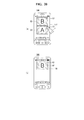
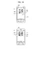
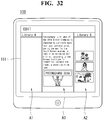
- FIGs. 30 to 32 are diagrams of an example of coupling and displaying data of the mobile terminal.
- the controller 180 may divide and display the display 151 into first to third areas A1 to A3.
- the first area A1 may be an area of displaying contents that are received from the first another terminal 200.
- the second area A2 may be an area of displaying contents that are received from the second another terminal 300.
- the third area A3 may be an area for editing the received contents.
- the user may select all or a part of contents of the first and second areas A1 and A2 using a finger F and may move the selected contents to the third area A3. That is, the user may select only specific contents of the received contents and perform an editing action.
- a selection of contents may be a drag touch action starting from a specific area.
- a text may be selected through an action of touching a text of the first area A1 and dragging to the third area A3.
- a text selected by the user may be displayed in the third area A3.
- the user may select image contents to couple to the selected text from the second area A2 and drag the image contents to the third area A3.
- a text and an image selected by the user may be displayed in the third area A3.
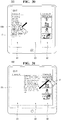
- FIGs. 33 and 34 are diagrams of an example of coupling and displaying data of the mobile terminal.
- the mobile terminal 100 may adjust to display or not to display a part of the first to third areas A1 to A3.
- first and second tags T1 and T2 may be displayed in a boundary portion of the first to third areas A1 to A3.
- the display of the first and/or second areas A1 and A2 may disappear or display based on the selected tag.
- the user can select the first tag T1 with a finger F.
- the display of the first area A1 may disappear.
- a form of the first tag T1 may change to a form of the third tag T3.
- FIGs. 35 to 38 are diagrams of a method of coupling data of the mobile terminal.
- the mobile terminal 100 may selectively edit the received data.
- first data DB1 and second data DB2 may be received from different electronic devices.
- Data belonging to the first data DB1 and the second data DB2 may be divided into first to third groups GI1 to GI3 based on positions thereof.
- the first group GI1 may be data belonging to only the first data DB1
- the second group GI2 may be data belonging to only the second data DB2.
- the third group GI3 may be data commonly belonging to the first and second data DB1 and DB2.
- the controller 180 may selectively store data of a group selected from the first to third groups G1 to G3.
- T3 and T6 of fields of the first data DB1 may be selected.
- T10, T12, T13, and T14 of fields of the second data DB2 may be selected.
- the controller 180 may form the third data DB3 with only selected fields.
- the formed third data DB3 may be stored in the memory 160 of the mobile terminal 100.
- first to fifth icons and a first widget corresponding to a specific application may be displayed in the display 151 (of the mobile terminal 100).
- first and second icons and a second widget may be displayed in a display 251 (of the another terminal 200).
- a list of icons and widgets corresponding to an application that does not exist in the mobile terminal 100 may be displayed in the display 151.
- a list of icons and widgets corresponding to an application that does not exist in the another terminal 200 may be displayed in the display 251 of the another terminal 200.
- a user may select a specific item from a displayed list.
- the selected specific item may be stored in a corresponding terminal.
- the another terminal 200 may include a specific setting value corresponding to a specific function such as Wi-Fi.
- the another terminal 200 may include a setting value that may approach a specific Wi-Fi service.
- the mobile terminal 100 may not include a specific setting of a Wi-Fi.
- a setting value of the another terminal 200 may be transmitted to the mobile terminal 100. That is, when the mobile terminal 100 receives a setting value from the another terminal 200, a received setting value may be applied.
- FIGs. 39 and 40 are diagrams of an example of coupling and displaying data of the mobile terminal.
- the mobile terminal 100 may use contents received from the another terminal 200 when performing a specific function.
- the mobile terminal 100 may perform a specific function, for example, a function of uploading a piece of writing to an SNS.
- the another terminal 200 may collide with the mobile terminal 100.
- the another terminal 200 may be in a state in which a specific image is selected.
- an attachment file AF may be added to the display 151.
- the attachment file AF may be an image file received from the another terminal 200. That is, the received data may be naturally coupled to a presently executing application without a separate manipulation of the user.
- the controller 180 may execute an application of writing an E-mail.
- the another terminal 200 may collide with the mobile terminal 100.
- the specific image SI received from the another terminal 200 may be automatically attached to an E-mail application that is executing in the mobile terminal 100.
- FIG. 41 is a diagram of transmitting data of the mobile terminal.
- the controller 180 may selectively transmit limited information to the another terminal 200 according to a state of the mobile terminal 100.
- the mobile terminal 100 may be in a lock state. That is, before the user performs a specific action or inputs a password, the mobile terminal 100 may be in a state in which execution of a function of the mobile terminal 100 is limited.
- the mobile terminal 100 When the mobile terminal 100 is in a lock state, the mobile terminal 100 may perform an action of colliding with the another terminal 200. When the mobile terminal 100 collides with the another terminal 200, data of the mobile terminal 100 may be transmitted to the another terminal 200.
- a type of data to be transmitted when the mobile terminal 100 is in a lock state may be different from a type of data to be transmitted in a normal state. That is, only limited specific data may be selectively transmitted. For example, only minimum information such as an E-mail address, a phone number, and an SNS address may be selectively transmitted.
- FIGs. 42 and 43 are diagrams of limiting transmitting data of the mobile terminal.
- the controller 180 may transmit data to the another terminal 200 under a predetermined limitation.
- the mobile terminal 100 may collide with the terminal 200 in an inverted state.
- data having an expiration time point may be transmitted.
- the user of the mobile terminal 100 may set and transmit an available period of the security card to the another terminal 200.
- the another terminal 200 having received data may notify the user that data having an expiration time point were transmitted.
- the above-described method of controlling the mobile terminal may be written as a computer program(s) and may be implemented in digital microprocessors that execute programs using a computer readable recording medium.
- the method of controlling the mobile terminal may be executed through software.
- the software may include code segments that perform required tasks. Programs or code segments may also be stored in a processor readable medium or may be transmitted according to a computer data signal combined with a carrier through a transmission medium or a communication network.
- the computer readable recording medium may be any data storage device that may store data that can be thereafter read by a computer system. Examples of the computer readable recording medium may include read-only memory (ROM), random-access memory (RAM), CD-ROMs, DVD ⁇ ROM, DVD-RAM, magnetic tapes, floppy disks, optical data storage devices.
- ROM read-only memory
- RAM random-access memory
- CD-ROMs CD-ROMs
- DVD ⁇ ROM DVD-RAM
- magnetic tapes floppy disks
- optical data storage devices optical data storage devices.
- the computer readable recording medium may also be distributed over network coupled computer systems so that the computer readable code is stored and executed in a distribution fashion.
- a mobile terminal may include a first touch screen configured to display a first object, a second touch screen configured to display a second object, and a controller configured to receive a first touch input applied to the first object and to link the first object to a function corresponding to the second object when receiving a second touch input applied to the second object while the first touch input is maintained.
- a method may be provided of controlling a mobile terminal.
- the method may include displaying a first object on the first touch screen, displaying a second object on the second touch screen, receiving a first touch input applied to the first object, and linking the first object to a function corresponding to the second object when a second touch input applied to the second object is received while the first touch input is maintained.
- a mobile terminal may comprise: a display; a sensing unit to sense a motion of the mobile terminal; a wireless communication unit to wirelessly exchange data with at least one other terminal; and a controller to display, on the display, data received from the at least one other terminal through the wireless communication unit based on a transmission direction determined according to the motion sensed through the sensing unit.
- the wireless communication unit includes a near field communication (NFC) module, wherein the controller determines the transmission direction when the at least one other terminal is provided in a communication available area of the NFC communication module.
- NFC near field communication
- the controller controls the display to distinguish data stored in the memory from the received data.
- the controller changes a display position of the received data based on a touch signal received through the display.
- the controller applies the received data to an application that is being executed on the mobile terminal.
- Embodiments may provide a mobile terminal and a method of controlling the mobile terminal that may easily transmit and receive data in a determined direction based on a result acquired through a sensing unit.
- any reference in this specification to "one embodiment,” “an embodiment,” “example embodiment,” etc. means that a particular feature, structure, or characteristic described in connection with the embodiment is included in at least one embodiment of the invention.
- the appearances of such phrases in various places in the specification are not necessarily all referring to the same embodiment.
Abstract
Description
- Embodiments of the present invention may relate to a mobile terminal and a method of controlling a mobile terminal. The mobile terminal may easily transmit and receive data in a determined direction based on a result received from a sensing unit.
- As functions of terminals such as personal computers, laptop computers, cellular phones diversify, the terminals may become multimedia players having multiple functions for capturing pictures or moving images, playing music, moving image files and games and/or receiving broadcasting programs.
- Terminals may be mobile terminals and/or stationary terminals. The mobile terminals may be handheld terminals and/or vehicle mount terminals based on whether users may personally carry the terminals. Terminals including mobile terminals may provide an increased number of complex and various functions.
- Arrangements and embodiments may be described in detail with reference to the following drawings in which like reference numerals refer to like elements wherein:
-
FIG. 1 is a block diagram of a mobile terminal according to an embodiment; -
FIG. 2A is a front perspective view of the mobile terminal according to an embodiment; -
FIG. 2B is a rear perspective view of the mobile terminal according to an embodiment; -
FIGS. 2C and2D illustrate forms of the mobile terminal and display screens according to various embodiments; -
FIG. 3 is a view for explaining a proximity depth of a proximity sensor; -
FIG. 4 is a block diagram showing a short range communication module of a mobile terminal according to an embodiment; -
FIG. 5 is a diagram showing a system environment including a mobile terminal according to an embodiment; -
FIG. 6 illustrates an example in which a mobile terminal according to an embodiment forms a communication link with another electronic device; -
FIG. 7 is a flowchart showing operation of the mobile terminal (ofFIG. 1 ); -
FIG. 8 is a message flow diagram between another terminal and the mobile terminal (ofFIG. 1 ); -
FIG. 9 is a diagram showing near field communication (NFC) activation of the mobile terminal; -
FIGS. 10 to 12 are diagrams showing a process of determining a data transmission direction of the mobile terminal; -
FIGS. 13 and14 are diagrams showing an example of determining a data transmission direction of the mobile terminal; -
FIGS. 15 and16 are diagrams showing an example of determining a data transmission direction of the mobile terminal; -
FIG. 17 is a diagram showing an example of determining a data transmission direction of the mobile terminal; -
FIGS. 18 to 22 are diagrams of a process of coupling and displaying data of the mobile terminal; -
FIGS. 23 to 25 are diagrams showing an example of coupling and displaying data of the mobile terminal; -
FIGS. 26 and27 are diagrams showing an example of coupling and displaying data of the mobile terminal; -
FIG. 28 is a diagram of an example of coupling and displaying data of the mobile terminal; -
FIG. 29 is a diagram of an example of coupling and displaying data of the mobile terminal; -
FIGS. 30 to 32 are diagrams of an example of coupling and displaying data of the mobile terminal; -
FIGS. 33 and34 are diagrams of an example of coupling and displaying data of the mobile terminal; -
FIGS. 35 to 38 are diagrams of a method of coupling data of the mobile terminal; -
FIGS. 39 and40 are diagrams of an example of coupling and displaying data of the mobile terminal ofFIG. 7 ; -
FIG. 41 is a diagram showing transmitting data of the mobile terminal; and -
FIGS. 42 and43 are diagrams showing a limitation of transmitting data of the mobile terminal. - Arrangements and embodiments may now be described more fully with reference to the accompanying drawings, in which exemplary embodiments may be shown. Embodiments may, however, be embodied in many different forms and should not be construed as being limited to embodiments set forth herein; rather, embodiments may be provided so that this disclosure will be thorough and complete, and will fully convey the concept to those skilled in the art.
- A mobile terminal may be described below with reference to the accompanying drawings. In the following description, suffixes "module" and "unit" may be given to components of the mobile terminal in consideration of only facilitation of description and do not have meanings or functions discriminated from each other.
- The mobile terminal may include a cellular phone, a smart phone, a laptop computer, a digital broadcasting terminal, personal digital assistants (PDA), a portable multimedia player (PMP), a navigation system and/or so on.
-
FIG. 1 is a block diagram of a mobile terminal according to an embodiment. Other embodiments, configurations and arrangements may also be provided. - As shown, the
mobile terminal 100 may include a wireless communication unit 110 (or radio communication unit), an audio/video (A/V)input unit 120, auser input unit 130, asensing unit 140, anoutput unit 150, amemory 160, aninterface 170, acontroller 180, and apower supply 190. The components shown inFIG. 1 may be essential parts and/or a number of components included in themobile terminal 100 may vary. Components of themobile terminal 100 may now be described. - The
wireless communication unit 110 may include at least one module that enables radio communication between themobile terminal 100 and a radio communication system or between themobile terminal 100 and a network in which themobile terminal 100 is located. For example, thewireless communication unit 110 may include abroadcasting receiving module 111, amobile communication module 112, awireless Internet module 113, a short range communication module 114 (or local area communication module), and a location information module 115 (or position information module). - The broadcasting receiving
module 111 may receive broadcasting signals and/or broadcasting related information from an external broadcasting management server through a broadcasting channel. The broadcasting channel may include a satellite channel and a terrestrial channel, and the broadcasting management server may be a server that generates and transmits broadcasting signals and/or broadcasting related information or a server that receives previously created broadcasting signals and/or broadcasting related information and transmits the broadcasting signals and/or broadcasting related information to a terminal. - The broadcasting signals may include not only TV broadcasting signals, radio broadcasting signals, and data broadcasting signals but also signals in the form of a combination of a TV broadcasting signal and a radio broadcasting signal. The broadcasting related information may be information on a broadcasting channel, a broadcasting program or a broadcasting service provider, and may be provided even through a mobile communication network. In the latter case, the broadcasting related information may be received by the
mobile communication module 112. - The broadcasting related information may exist in various forms. For example, the broadcasting related information may exist in the form of an electronic program guide (EPG) of a digital multimedia broadcasting (DMB) system or in the form of an electronic service guide (ESG) of a digital video broadcast-handheld (DVB-H) system.
- The broadcasting receiving
module 111 may receive broadcasting signals using various broadcasting systems. More particularly, the broadcasting receivingmodule 111 may receive digital broadcasting signals using digital broadcasting systems such as a digital multimedia broadcasting-terrestrial (DMB-T) system, a digital multimedia broadcasting-satellite (DMB-S) system, a media forward link only (MediaFLO) system, a DVB-H and integrated services digital broadcast-terrestrial (ISDB-T) systems. The broadcasting receivingmodule 111 may receive signals from broadcasting systems providing broadcasting signals other than the above-described digital broadcasting systems. - The broadcasting signals and/or broadcasting related information received through the broadcasting receiving
module 111 may be stored in thememory 160. Themobile communication module 112 may transmit/receive a radio signal to/from at least one of a base station, an external terminal and a server on a mobile communication network. The radio signal may include a voice call signal, a video telephony call signal or data in various forms according to transmission and reception of text/multimedia messages. - The
wireless Internet module 113 may correspond to a module for wireless Internet access and may be included in themobile terminal 100 or may be externally attached to themobile terminal 100. Wireless LAN (WLAN or Wi-Fi), wireless broadband (Wibro), world interoperability for microwave access (Wimax), high speed downlink packet access (HSDPA) and so on may be used as a wireless Internet technique. - The short
range communication module 114 may correspond to a module for short range communication. Further, Bluetooth®, radio frequency identification (RFID), infrared data association (IrDA), ultra wideband (UWB) and/or ZigBee® may be used as a short range communication technique. - The
location information module 115 may confirm or obtain a location or a position of themobile terminal 100. Thelocation information module 115 may obtain position information by using a global navigation satellite system (GNSS). The GNSS is a terminology describing a radio navigation satellite system that revolves around the earth and transmits reference signals to predetermined types of radio navigation receivers such that the radio navigation receivers can determine their positions on the earth's surface or near the earth's surface. The GNSS may include a global positioning system (GPS) of the United States, Galileo of Europe, a global orbiting navigational satellite system (GLONASS) of Russia, COMPASS of China, and a quasi-zenith satellite system (QZSS) of Japan, for example. - A global positioning system (GPS) module is a representative example of the
location information module 115. The GPS module may calculate information on distances between one point or object and at least three satellites and information on a time when distance information is measured and apply trigonometry to the obtained distance information to obtain three-dimensional position information on the point or object according to latitude, longitude and altitude at a predetermined time. - A method of calculating position and time information using three satellites and correcting the calculated position and time information using another satellite may also be used. Additionally, the GPS module may continuously calculate a current position in real time and calculate velocity information using the location or position information.
- The A/
V input unit 120 may input (or receive) an audio signal and/or a video signal. The A/V input unit 120 may include acamera 121 and amicrophone 122. Thecamera 121 may process image frames of still images or moving images obtained by an image sensor in a video telephony mode or a photographing mode. The processed image frames may be displayed on adisplay 151, which may be a touch screen. - The image frames processed by the
camera 121 may be stored in thememory 160 or may be transmitted to an external device through thewireless communication unit 110. Themobile terminal 100 may also include at least twocameras 121. - The
microphone 122 may receive an external audio signal in a call mode, a recording mode and/or a speech recognition mode, and themicrophone 122 may process the received audio signal into electric audio data. The audio data may then be converted into a form that can be transmitted to a mobile communication base station through themobile communication module 112 and output in the call mode. Themicrophone 122 may employ various noise removal algorithms (or noise canceling algorithm) for removing or reducing noise generated when the external audio signal is received. - The
user input unit 130 may receive input data for controlling operation of the mobile terminal 100 from a user. Theuser input unit 130 may include a keypad, a dome switch, a touch pad (constant voltage/capacitance), a jog wheel, a jog switch and/or so on. - The
sensing unit 140 may sense a current state of themobile terminal 100, such as an open/close state of themobile terminal 100, a position of themobile terminal 100, whether a user touches themobile terminal 100, a direction of themobile terminal 100, and acceleration/deceleration of themobile terminal 100, and thesensing unit 140 may generate a sensing signal for controlling operation of themobile terminal 100. For example, in an example of a slide phone, thesensing unit 140 may sense whether the slide phone is opened or closed. Further, thesensing unit 140 may sense whether thepower supply 190 supplies power and/or whether theinterface 170 is connected to an external device. Thesensing unit 140 may also include a proximity sensor 141. Thesensing unit 140 may sense a motion of themobile terminal 100. - The
output unit 150 may generate visual, auditory and/or tactile output, and theoutput unit 150 may include thedisplay 151, anaudio output module 152, analarm 153 and ahaptic module 154. Thedisplay 151 may display information processed by themobile terminal 100. Thedisplay 151 may display a user interface (UI) and/or a graphic user interface (GUI) related to a telephone call when themobile terminal 100 is in the call mode. Thedisplay 151 may also display a captured and/or received image, a UI or a GUI when themobile terminal 100 is in the video telephony mode or the photographing mode. - The
display 151 may include at least one of a liquid crystal display, a thin film transistor liquid crystal display, an organic light-emitting diode display, a flexible display and/or a three-dimensional display. Thedisplay 151 may be of a transparent type or a light transmissive type. That is, thedisplay 151 may include a transparent display. - The transparent display may be a transparent liquid crystal display. A rear structure of the
display 151 may also be of a light transmissive type. Accordingly, a user may see an object located behind the body (of the mobile terminal 100) through the transparent area of the body of themobile terminal 100 that is occupied by thedisplay 151. - The
mobile terminal 100 may also include at least twodisplays 151. For example, themobile terminal 100 may include a plurality ofdisplays 151 that are arranged on a single face at a predetermined distance or integrated displays. The plurality ofdisplays 151 may also be arranged on different sides. - When the
display 151 and a sensor sensing touch (hereafter referred to as a touch sensor) form a layered structure that is referred to as a touch screen, thedisplay 151 may be used as an input device in addition to an output device. The touch sensor may be in the form of a touch film, a touch sheet, and/or a touch pad, for example. - The touch sensor may convert a variation in pressure applied to a specific portion of the
display 151 or a variation in capacitance generated at a specific portion of thedisplay 151 into an electric input signal. The touch sensor may sense pressure of touch as well as position and area of the touch. - When the user applies a touch input to the touch sensor, a signal corresponding to the touch input may be transmitted to a touch controller. The touch controller may then process the signal and transmit data corresponding to the processed signal to the
controller 180. Accordingly, thecontroller 180 may detect a touched portion of thedisplay 151. - The proximity sensor 141 (of the sensing unit 140) may be located in an internal region of the
mobile terminal 100, surrounded by the touch screen, and/or near the touch screen. The proximity sensor 141 may sense an object approaching a predetermined sensing face or an object located near the proximity sensor 141 using an electromagnetic force or infrared rays without having mechanical contact. The proximity sensor 141 may have a lifetime longer than a contact sensor and may thus have a wide application in themobile terminal 100. - The proximity sensor 141 may include a transmission type photo-electric sensor, a direct reflection type photo-electric sensor, a mirror reflection type photo-electric sensor, a high-frequency oscillating proximity sensor, a capacitive proximity sensor, a magnetic proximity sensor, and/or an infrared proximity sensor. A capacitive touch screen may be constructed such that proximity of a pointer is detected through a variation in an electric field according to the proximity of the pointer. The touch screen (touch sensor) may be classified as a proximity sensor 141.
- For ease of explanation, an action of the pointer approaching the touch screen without actually touching the touch screen may be referred to as a proximity touch and an action of bringing the pointer into contact with the touch screen may be referred to as a contact touch. The proximity touch point of the pointer on the touch screen may correspond to a point of the touch screen at which the pointer is perpendicular to the touch screen.
- The proximity sensor 141 may sense the proximity touch and a proximity touch pattern (e.g., a proximity touch distance, a proximity touch direction, a proximity touch velocity, a proximity touch time, a proximity touch position, a proximity touch moving state, etc.). Information corresponding to the sensed proximity touch action and proximity touch pattern may then be displayed on the touch screen.
- The
audio output module 152 may output audio data received from thewireless communication unit 110 or stored in thememory 160 in a call signal receiving mode, a telephone call mode or a recording mode, a speech recognition mode and a broadcasting receiving mode. Theaudio output module 152 may output audio signals related to functions, such as a call signal incoming tone and a message incoming tone, performed in themobile terminal 100. Theaudio output module 152 may include a receiver, a speaker, a buzzer, and/or the like. Theaudio output module 152 may output sounds through an earphone jack. The user may hear the sounds by connecting an earphone to the earphone jack. - The
alarm 153 may output a signal for indicating generation of an event of themobile terminal 100. For example, an alarm may be generated when receiving a call signal, receiving a message, inputting a key signal, and/or inputting a touch. Thealarm 153 may also output signals in forms different from video signals or audio signals, for example, a signal for indicating generation of an event through vibration. The video signals and/or the audio signals may also be output through thedisplay 151 or theaudio output module 152. - The
haptic module 154 may generate various haptic effects that the user can feel. One example of the haptic effects is vibration. An intensity and/or pattern of vibration generated by thehaptic module 154 may also be controlled. For example, different vibrations may be combined and output or may be sequentially output. - The
haptic module 154 may generate a variety of haptic effects including an effect of stimulus according to an arrangement of pins vertically moving against a contact skin surface, an effect of stimulus according to a jet force or sucking force of air through a jet hole or a sucking hole, an effect of stimulus of rubbing the skin, an effect of stimulus according to contact of an electrode, an effect of stimulus using an electrostatic force, and an effect according to a reproduction of cold and warmth using an element capable of absorbing or radiating heat in addition to vibrations. - The
haptic module 154 may not only transmit haptic effects through direct contact but may also allow the user to feel haptic effects through a kinesthetic sense of the user's fingers or arms. Themobile terminal 100 may also include a plurality ofhaptic modules 154. - The
memory 160 may store a program for operations of thecontroller 180 and/or temporarily store input/output data such as a phone book, messages, still images, and/or moving images. Thememory 160 may also store data about vibrations and sounds in various patterns that are output from when a touch input is applied to the touch screen. - The
memory 160 may include at least a flash memory, a hard disk type memory, a multimedia card micro type memory, a card type memory, such as SD or XD memory, a random access memory (RAM), a static RAM (SRAM), a read-only memory (ROM), an electrically erasable programmable ROM (EEPROM), a programmable ROM (PROM) magnetic memory, a magnetic disk and/or an optical disk. Themobile terminal 100 may also operate in relation to a web storage that performs a storing function of thememory 160 on the Internet. - The
interface 170 may serve as a path to external devices connected to themobile terminal 100. Theinterface 170 may receive data from the external devices or power and transmit the data or power to internal components of themobile terminal 100 or transmit data of themobile terminal 100 to the external devices. For example, theinterface 170 may include a wired/wireless headset port, an external charger port, a wired/wireless data port, a memory card port, a port for connecting a device having a user identification module, an audio I/O port, a video I/O port, and/or an earphone port. - The
interface 170 may also interface with a user identification module that is a chip that stores information for authenticating authority to use themobile terminal 100. For example, the user identification module may be a user identify module (UIM), a subscriber identify module (SIM) and/or a universal subscriber identify module (USIM). An identification device (including the user identification module) may also be manufactured in the form of a smart card. Accordingly, the identification device may be connected to themobile terminal 100 through a port of theinterface 170. - The
interface 170 may also be a path through which power from an external cradle is provided to themobile terminal 100 when themobile terminal 100 is connected to the external cradle or a path through which various command signals input by the user through the cradle are transmitted to themobile terminal 100. The various command signals or power input from the cradle may be used as signals for confirming whether themobile terminal 100 is correctly set in the cradle. - The
controller 180 may control overall operations of themobile terminal 100. For example, thecontroller 180 may perform control and processing for voice communication, data communication and/or video telephony. Thecontroller 180 may also include amultimedia module 181 for playing multimedia. Themultimedia module 181 may be included in thecontroller 180 or may be separated from thecontroller 180. - The
controller 180 may perform a pattern recognition process capable of recognizing handwriting input or picture-drawing input applied to the touch screen as characters or images. Thepower supply 190 may receive external power and internal power and provide power required for operations of the components of themobile terminal 100 under control of thecontroller 180. - According to hardware implementation, embodiments may be implemented using at least one of application specific integrated circuits (ASICs), digital signal processors (DSPs), digital signal processing devices (DSPDs), programmable logic devices (PLDs), field programmable gate arrays (FPGAs), processors, controllers, micro-controllers, microprocessors, and/or electrical units for executing functions. Embodiments may be implemented by the
controller 180. - According to software implementation, embodiments such as procedures or functions may be implemented with a separate software module that executes at least one function or operation. Software codes may be implemented according to a software application written in an appropriate software language. The software codes may be stored in the
memory 160 and executed by thecontroller 180. -
FIG. 2A is a front perspective view of a mobile terminal (or a handheld terminal) according to an embodiment. - The
mobile terminal 100 may be a bar type terminal body. However, embodiments are not limited to a bar type terminal and may be applied to terminals of various types including slide type, folder type, swing type and/or swivel type terminals having at least two bodies that are relatively movably combined. - The terminal body may include a case (a casing, a housing, a cover, etc.) that forms an exterior of the
mobile terminal 100. In this embodiment, the case may be divided into afront case 101 and arear case 102. Various electronic components may be arranged in the space formed between thefront case 101 and therear case 102. At least one middle case may be additionally provided between thefront case 101 and therear case 102. - The cases may be formed of plastics through injection molding or made of a metal material such as stainless steel (STS) or titanium (Ti).
- The
display 151, theaudio output unit 152, thecamera 121, theuser input unit 130/131 and 132, themicrophone 122 and theinterface 170 may be arranged (or provided) in the terminal body, and more specifically may be arranged (or provided) in thefront case 101. - The
display 151 may occupy most of the main face of thefront case 101. Theaudio output unit 152 and thecamera 121 may be arranged in a region in proximity to one of both ends of thedisplay 151 and theuser input unit 131, and themicrophone 122 may be located in a region in proximity to another end of thedisplay 151. Theuser input unit 132 and theinterface 170 may be arranged (or provided) on sides of thefront case 101 and therear case 102. - The
user input unit 130 may receive commands for controlling operation of themobile terminal 100, and may include a plurality of operatingunits units units - The first and
second operating units first operating unit 131 may receive commands such as start, end and scroll and thesecond operating unit 132 may receive commands such as control of a volume of sound output from theaudio output unit 152 or conversion of thedisplay 151 to a touch recognition mode. -
FIG. 2B is a rear perspective view of the mobile terminal (shown inFIG. 2A ) according to an embodiment. - Referring to
FIG. 2A , a camera 121' may be additionally attached to the rear side of the terminal body (i.e., the rear case 102). The camera 121' may have a photographing direction opposite to that of the camera 121 (shown inFIG. 2A ) and may have pixels different from those of the camera 121 (shown inFIG. 2A ). - For example, it may be desirable that the
camera 121 has low pixels such that thecamera 121 may capture an image of a face of a user and transmit the image to a receiving part in case of video telephony while the camera 121' has high pixels because the camera 121' captures an image of a general object and does not immediately transmit the image in many cases. Thecameras 121 and 121' may be attached (or provided) to the terminal body such that thecameras 121 and 121' may rotate or pop-up. - A
flash bulb 123 and amirror 124 may be additionally provided in proximity to the camera 121'. Theflash bulb 123 may light an object when the camera 121' takes a picture of the object. Themirror 124 may be used for the user to look at his/her face in the mirror when the user wants to self-photograph himself/herself using the camera 121'. - An audio output unit 152' may be additionally provided on the rear side of the terminal body. The audio output unit 152' may achieve a stereo function with the audio output unit 152 (shown in
FIG. 2A ) and may be used for a speaker phone mode when the terminal is used for a telephone call. - A broadcasting signal receiving antenna may be additionally attached (or provided) to the side of the terminal body in addition to an antenna for telephone calls. The antenna constructing a part of the broadcasting receiving module 111 (shown in
FIG. 1 ) may be set in the terminal body such that the antenna may be pulled out of the terminal body. - The
power supply 190 for providing power to themobile terminal 100 may be set in the terminal body. Thepower supply 190 may be included in the terminal body or may be detachably attached to the terminal body. - A
touch pad 135 for sensing touch may be attached to therear case 102. Thetouch pad 135 may be of a light transmission type, such as thedisplay 151. In this example, if thedisplay 151 outputs visual information through both sides thereof, the visual information may be recognized (or determined) by thetouch pad 135. The information output through both sides of thedisplay 151 may be controlled by thetouch pad 135. Otherwise, a display may be additionally attached (or provided) to thetouch pad 135 such that a touch screen may be arranged (or provided) even in therear case 102. - The
touch pad 135 may operate in connection with thedisplay 151 of thefront case 101. Thetouch pad 135 may be located in parallel with thedisplay 151 behind thedisplay 151. Thetouch panel 135 may be identical to or smaller than thedisplay 151 in size. -
FIGs. 2C and2D illustrate themobile terminal 100 and thedisplay 151 according to various embodiments. - Referring to
FIG. 2C , thedisplay 151 may include a first display and a second display that are physically separated from each other. In a folder type or slide type mobile terminal having two bodies connected through a hinge or a slide, the first display (or main display) may be formed on the inner face or outer face of one of the bodies, and the second display (or sub display) may be formed on the inner face or outer face of the other body. The sub display may be separated from the mobile terminal and may be detachably combined with the mobile terminal body through an interface to display data from themobile terminal 100. - The
display 151 may include first and second displays that may be logically separated from each other in a display panel, as shown inFIG. 2D . -
FIG. 3 is a view for explaining a proximity depth of a proximity sensor. - As shown in
FIG. 3 , when a pointer (such as a user's finger) approaches the touch screen, the proximity sensor located inside or near the touch screen may sense the approach of the pointer, and may output a proximity signal. - The proximity sensor may be constructed such that the proximity sensor outputs a proximity signal according to a distance between the pointer approaching the touch screen and the touch screen (referred to as "proximity depth").
- The distance in which the proximity signal is output when the pointer approaches the touch screen may be referred to as a detection distance. The proximity depth may be determined by using a plurality of proximity sensors having different detection distances and by comparing proximity signals respectively output from the proximity sensors.
-
FIG. 3 shows a section of the touch screen in which proximity sensors capable of sensing three proximity depths may be provided. Proximity sensors capable of sensing less than three or more than four proximity depths may be provided in the touch screen. - More specifically, when the pointer completely contacts the touch screen (D0), it may be recognized as contact touch. When the pointer is located within a distance D1 from the touch screen, it may be recognized as a proximity touch of a first proximity depth. When the pointer is located in a range between the distance D1 and a distance D2 from the touch screen, it may be recognized as a proximity touch of a second proximity depth. When the pointer is located in a range between the distance D2 and a distance D3 from the touch screen, it may be recognized as a proximity touch of a third proximity depth. When the pointer is located greater than the distance D3 from the touch screen, it may be recognized as cancellation of the proximity touch.
- Accordingly, the
controller 180 may recognize the proximity touch as various input signals according to proximity distance and proximity position of the pointer with respect to the touch screen, and the controller 810 may perform various operation controls according to the input signals. -
FIG. 4 is a block diagram showing a shortrange communication module 114 of themobile terminal 100 according to an embodiment. As shown inFIG. 4 , the shortrange communication module 114 may include a near field communication (NFC)module 117, aBluetooth communication module 118 and so on. - The
NFC communication module 117 may perform data communication with devices positioned at a distance within 10 cm (preferably within 4 cm) using very short-range contactless data transfer technology related to radio frequency identification (RFID). An electronic device that adapts NFC technology may communicate with another electronic device that adapts NFC technology through at least one of a reader mode, a card emulation mode, and/or a pier to pier mode, for example. TheNFC communication module 117 may be described with reference toFIG. 5 . - The
Bluetooth communication module 118 may perform data communication with devices within aradius 10 to 100 m using Bluetooth, which is one type of short range wireless communication formats. For reference, Bluetooth is short range wireless networking technology that was developed by a Bluetooth special interest group (SIG). - The block diagram shown in
FIG. 4 is an example of the shortrange communication module 114 according to the present embodiment, and elements of the shortrange communication module 114 may not be essential elements. The shortrange communication module 114 may include elements more than or fewer than shown inFIG. 4 . -
FIG. 5 is a diagram illustrating a system environment that includes themobile terminal 100. As shown inFIG. 5 , the system environment may be formed with themobile terminal 100 and one or more otherelectronic devices mobile terminal 100. Theelectronic devices - The system environment may include elements fewer than or more than shown in
FIG. 5 . InFIG. 5 , in order to describe a communication link forming a characteristic of themobile terminal 100, only certain elements for forming a communication link may be shown. - In
FIG. 5 , the system environment may be formed with mobile terminals, although electronic devices described herein may be a random electronic device for supporting NFC communication. That is, theelectronic devices - In
FIG. 5 , themobile terminal 100 may form an NFC link with the otherelectronic devices mobile terminal 100 may form a wireless communication link with the otherelectronic devices - Referring to
FIG. 5 , themobile terminal 100 may include thecontroller 180, theNFC communication module 117, theBluetooth communication module 118, and/or a Wi-Fi communication module 119. - The
controller 180 may control elements within themobile terminal 100. TheNFC communication module 117 may enable themobile terminal 100 to form an NFC link with otherelectronic devices NFC communication module 117 may indicate an NFC forum device. TheNFC communication module 117 may be referred to as a short range communication means. - As shown in
FIG. 5 , theNFC communication module 117 may form an NFC link through tagging with an NFC communication module of the otherelectronic devices - The
NFC communication module 117 may communicate in various modes with the NFC communication module of the otherelectronic devices - When the
NFC communication module 117 operates in the card emulation mode, the NFC communication module 117 (of the mobile terminal 100) may function as a card (i.e., a tag). In this example, the NFC communication module of the otherelectronic devices NFC communication module 117 of themobile terminal 100. - When the
NFC communication module 117 operates in the reader mode, the NFC communication module 117 (of the mobile terminal 100) may function as a reader. In this example, theNFC communication module 117 of themobile terminal 100 may acquire data from the NFC communication module of the otherelectronic devices - When the
NFC communication module 117 operates in the peer to peer mode, the NFC communication module 117 (of the mobile terminal 100) and the NFC communication module of the otherelectronic devices - A mode of the
NFC communication module 117 may be determined according to a predetermined reference. For example, a mode of theNFC communication module 117 may be set based on a user input, or a predetermined algorithm. - The
mobile terminal 100 may form an NFC link through theNFC communication module 117 with the otherelectronic devices electronic devices Bluetooth communication module 118 and/or the Wi-Fi communication module 119. Therefore, even if the NFC communication link is disconnected, themobile terminal 100 may continue to perform data communication with the otherelectronic devices Bluetooth communication module 118 and/or the Wi-Fi communication module 119. - After the NFC link is formed, a series of processes of forming another communication link in order to enable the
mobile terminal 100 to continue to communicate with the otherelectronic devices - Referring to
FIG. 5 , in themobile terminal 100, a handover may be performed from an NFC communication link to a Bluetooth communication link or a Wi-Fi communication link, although a range is not limited thereto. For example, themobile terminal 100 may perform a handover to various communication links, such as an RFID communication link and a wireless gigabit (WiGig) communication link. - Although not shown in
FIG. 5 , the otherelectronic devices mobile terminal 100. For example, the otherelectronic devices - The handover may indicate that the
mobile terminal 100 performs data communication by forming an NFC link and then forming another communication link with the otherelectronic devices mobile terminal 100 and the otherelectronic devices - A handover process of the
mobile terminal 100 may be described with reference to the drawings. For ease of description, a handover process may be described with reference to the system environment shown inFIG. 5 . Embodiments are not limited to a specific environment or a specific device. -
FIG. 6 illustrates an example in which themobile terminal 100 forms a communication link with the anotherelectronic device 200. A process of forming a communication link may be described with reference to the drawings. - Referring to
FIG. 6 , themobile terminal 100 may transmit a handover request message to the another electronic device 200 (S110). Before operation S110, themobile terminal 100 and the anotherelectronic device 200 may form a communication link through a first communication means. As one example, themobile terminal 100 may form an NFC link through tagging to anNFC communication module 220 included in the anotherelectronic device 200. - When the NFC link is formed, the
mobile terminal 100 may transmit a message (e.g. a handover request message) for a handover request to the anotherelectronic device 200 through the NFC link. - As the
mobile terminal 100 transmits the handover request message to the anotherelectronic device 200, themobile terminal 100 and the anotherelectronic device 200 may start a protocol for forming another communication link through the NFC link formed between themobile terminal 100 and the anotherelectronic device 200. - The
mobile terminal 100 may be a handover requester, and the anotherelectronic device 200 may be a handover selector. The handover requester may be a device for starting a handover protocol by transmitting a handover request message to another NFC electronic device. The handover selector may be an NFC device for writing and responding with a handover selection message as a response to the received handover request message. - That is, the handover requester (i.e., a handover request device) and the handover selector (i.e., a handover selection device) may be relative concepts to be determined based on transmission of a handover request message or transmission of a handover selection message. Therefore, when the another
electronic device 200 transmits a handover request message to themobile terminal 100 based on a situation, themobile terminal 100 may be a handover selector and the anotherelectronic device 200 may be a handover requester. - The handover request message may include information about another communication module that is supported by the
mobile terminal 100. For example, as shown inFIG. 6 , when themobile terminal 100 supports Bluetooth and/or Wi-Fi, the handover request message may include information about Bluetooth and/or Wi-Fi that are supported by themobile terminal 100. - A priority order may be set to communication technology used for handover and that is supported by the
mobile terminal 100. For example, as shown inFIG. 6 , the handover request message may have information about a communication module for supporting communication technology having a high priority order at a front thereof and that has information about a communication module for supporting communication technology having a low priority order at a rear thereof. Referring to the handover request message (shown inFIG. 6 ), it may be determined that information about a Wi-Fi communication module has a priority order higher than information about a Bluetooth communication module. - Another
electronic device 200 having received the handover request message, may transmit a response to the handover request message to the mobile terminal 100 (S120). For example, the anotherelectronic device 200 may generate a handover selection message as an example of a response to the handover request message through the NFC link, and may transmit the generated handover selection message to themobile terminal 100. - The another
electronic device 200 may determine a communication module included in themobile terminal 100 by analyzing the handover request message and based on the determination may provide information about a communication module included in the anotherelectronic device 200 to themobile terminal 100. That is, information about a communication module included in the handover selection message may include information about a communication module included in the anotherelectronic device 200 from among communication modules included in themobile terminal 100. - Referring to
FIG. 6 , acontroller 210 of the anotherelectronic device 200 may determine that theBluetooth communication module 118 and the Wi-Fi communication module 119 are included in themobile terminal 100 by analyzing the received handover request message and transmitting a handover selection message including information about aBluetooth communication module 230 and a Wi-Fi communication module 240 included in the anotherelectronic device 200 to themobile terminal 100. - When a handover selection message is received from the another
electronic device 200, thecontroller 180 of themobile terminal 100 may determine that theBluetooth communication module 230 and the Wi-Fi communication module 240 are included in the anotherelectronic device 200 by analyzing the handover selection message and may receive (or acquire) information thereof. - Thereafter, the
mobile terminal 100 may form a communication link with communication modules included in the anotherelectronic device 200 based on the received information, and themobile terminal 100 may perform data communication with the anotherelectronic device 200 through the formed communication link (S120). - For example, in order to change an NFC communication link with the another
electronic device 200 to the Bluetooth communication link, the controller 180 (of the mobile terminal 100) may perform a Bluetooth pairing with the anotherelectronic device 200. Thereby, themobile terminal 100 may continue to perform communication according to a Bluetooth protocol by converting a communication link with the anotherelectronic device 200 from the NFC communication link to the Bluetooth communication link. - As handover of a communication link between the
mobile terminal 100 and the anotherelectronic device 200 is performed, the NFC communication link to the Bluetooth communication link, data communication may be performed, and data may be exchanged with a transmission speed faster than the NFC link, even if themobile terminal 100 and the anotherelectronic device 200 are no longer positioned within an NFC communication range (shown inFIG.6 ). - In other words, when the
mobile terminal 100 is a smart phone, the user may bring the smart phone to a periphery of the anotherelectronic device 200 and may perform tagging with the anotherelectronic device 200, and thus an NFC link may be formed, and by performing a handover protocol, a communication means may be changed to the Bluetooth communication link. Therefore, even if the user takes a smart phone out of an NFC communication range, the smart phone and the anotherelectronic device 200 may continue to perform data communication using the Bluetooth communication link. - Further, the controller 180 (of the mobile terminal 100) may perform a process of forming a Wi-Fi communication link with the another
electronic device 200 in order to change the NFC communication link with the anotherelectronic device 200 to the Wi-Fi communication link and perform data communication with the anotherelectronic device 200 through the formed Wi-Fi communication link. Therefore, themobile terminal 100 may perform data communication with the anotherelectronic device 200 even outside a NFC communication range with a data transmission and reception speed faster than the NFC communication link. - In this example, when a plurality of communication links exist that may be changed from the NFC communication link, the controller 180 (of the mobile terminal 100) may perform handover for only a communication link selected from the plurality of communication links and may perform handover to the plurality of communication links. Further, when a communication link for performing a handover is selected from a plurality of communication links, the
controller 180 may select a communication link according to a predetermined priority order. -
FIG. 7 is a flowchart of an operation of the mobile terminal. - As shown in
FIG. 7 , thecontroller 180 may activate the NFC communication module 117 (S10). - The
NFC communication module 117 may be selectively activated or inactivated by a user's selection and/or a control operation of thecontroller 180. For example, in a situation in which a NFC communication is not used, because electricity is not supplied to theNFC communication module 117, consumption of a battery may be reduced. Therefore, when theNFC communication module 117 is inactivated, in order to perform communication of an NFC method, theNFC communication module 117 may be activated. - The
controller 180 may determine a transmission direction of data (S20). - Data may be transmitted from the
mobile terminal 100 to another terminal through the NFC communication module, or data may be transmitted from another terminal to themobile terminal 100 through theNFC communication module 117. - A transmission direction of data may be determined based on the user's manipulation form of a main body of the
mobile terminal 100. For example, a transmission direction of data may be determined by an action of colliding themobile terminal 100 with another terminal. That is, when performing an action of colliding themobile terminal 100 with another terminal in a stationary state at a specific position by moving themobile terminal 100, data of themobile terminal 100 may be transmitted to the another terminal. - A transmission direction of data may be determined based on a form advancing into an area in which a NFC communication is available. For example, when the
mobile terminal 100 enters into an NFC area of another terminal waiting for NFC communication, data of themobile terminal 100 may be transmitted to another terminal. - A transmission direction of data may be determined based on a form in which the user performs a touch. For example, when a drag touch action is performed from one direction to another direction on the
display 151, data of themobile terminal 100 may be transmitted to another terminal in an advancing direction of a drag touch action. - When a transmission direction of data is determined, the
controller 180 may receive (or acquire) data based on the determined transmission direction (S30). - Data may be information stored in the
memory 160. For example, data may be a text, an image, and/or a moving picture stored in thememory 160. - When a transmission direction of data is determined from another terminal to the
mobile terminal 100, a text, for example, may be transmitted from the another terminal to themobile terminal 100. That is, themobile terminal 100 may receive (or acquire) data from the other terminal based on a determined direction. - Operation S40 of coupling the acquired (or received) data and operation S50 of displaying the coupled data may be performed.
- The
controller 180 may couple the received data (S40). For example, themobile terminal 100 may couple the received information to previously stored information in thememory 160. Alternatively, themobile terminal 100 may couple first information received from a first terminal and second information received from a second terminal. - The
controller 180 may generate data of a new form by coupling the received data. Therefore, a cooperation of generating one data as a plurality of persons separately operate in a plurality of electronic devices may be performed. Thecontroller 180 may control thedisplay 151 to display the coupled data (S50). -
FIG. 8 is a message flow diagram between another terminal and the mobile terminal (ofFIG. 1 ). - As shown in
FIG. 8 , themobile terminal 100 and the another terminal 200 may determine a transmission direction of data (S20). - A transmission direction of data may be determined by a control operation performed between the
mobile terminal 100 and the anotherterminal 200. For example, as described above, a transmission direction of data may be determined based on an action of colliding themobile terminal 100 with the another terminal 200, moving themobile terminal 100 into an NFC communication area of the another terminal 200, and/or performing a specific touch action in themobile terminal 100. - When a transmission direction of data is determined from the another terminal 200 to the
mobile terminal 100, the another terminal 200 may transmit data to the mobile terminal 100 (S31). - Data may be transmitted through communication using a NFC method. Furthermore, data may be transmitted by handover from communication using a NFC method to communication using a Wi-Fi method.
- When data is received, the
mobile terminal 100 may couple the acquired (or received) data (S40), and themobile terminal 100 may display the coupled data (S50). -
FIG. 9 is a diagram showing an NFC activation of the mobile terminal. - As shown in
FIG. 9 , thecontroller 180 may control thedisplay 151 to display a soft key SK for activating a NFC communication. - The soft key SK may be selectively displayed in the
display 151. For example, when a user performs a touch action of dragging an indicator area IA of thedisplay 151 in a lateral direction and/or in a vertical direction, the soft key SK may be displayed. When the user again performs the same touch action, the displayed soft key SK may disappear. - When activation of a specific function is toggled, the soft key SK may be selected. For example, when the soft key SK is touched one time, the
NFC communication module 117 may be activated, and when the soft key SK is touched again, theNFC communication module 117 may be inactivated. The soft key SK may include a button corresponding to other functions in which the user frequently uses in addition to a button related to theNFC communication module 117. - NFC communication may be activated through a
key button 131 provided in a surface of themobile terminal 100. For example, when an action of pressing the physicalkey button 131 is performed, thecontroller 180 may activate or inactivate theNFC communication module 117. -
FIGS. 10 to 12 are diagrams of a process of determining a data transmission direction of the mobile terminal. - As shown in
FIGs. 10 to 12 , themobile terminal 100 may determine a transmission direction of data based on a colliding action of themobile terminal 100 and the anotherterminal 200. - As shown in
FIG. 10A , themobile terminal 100 may be in a stationary state at a specific position, and the another terminal 200 may move toward themobile terminal 100. - Movement of the
mobile terminal 100 may be detected by an acceleration sensor, a terrestrial magnetism sensor, and/or a magnetic sensor included in thesensing unit 140. By a combination of an acceleration sensor, a terrestrial magnetism sensor, and/or a magnetic sensor, thesensing unit 140 may detect a change according to movement of themobile terminal 100. That is, a stationary state and a moving state of themobile terminal 100 may be detected by thesensing unit 140. A description in which thesensing unit 140 detects movement of themobile terminal 100 may be applied to the anotherterminal 200. For example, as shown inFIG. 10A , when themobile terminal 100 stops and the another terminal 200 moves, controllers of themobile terminal 100 and the another terminal 200 may determine, based on a detection value of thesensing unit 140, that a corresponding device is moving or stops. - As shown in
FIG. 10B , the moving another terminal 200 may collide with themobile terminal 100 that is stopped at a specific position. At a collision moment, controllers of the two devices may determine which terminal collides with which terminal based on a detection result of thesensing unit 140. For example, in an example ofFIG. 10B , as themobile terminal 100 stops and the another terminal 200 moves, themobile terminal 100 and the another terminal 200 may collide. In such an example, the user may have an intention to move data from the another terminal 200 to themobile terminal 100. - As shown in
FIGs. 11A and 11B , the user may collide the another terminal 200 and themobile terminal 100 by moving themobile terminal 100 to the stationary another terminal 200. In this example, when themobile terminal 100 collides with the stationary another terminal 200, the user may have an intention to move data from themobile terminal 100 to the anotherterminal 200. - As shown in
FIGs. 12A and 12B , the user may collide themobile terminal 100 and the another terminal 200 by moving both themobile terminal 100 and the anotherterminal 200. In this example, when twoterminals terminals -
FIGs. 13 and14 are diagrams of an example of determining a data transmission direction of the mobile terminal. - As shown in
FIGs. 13 and14 , a transmission direction of data may be determined according to whether themobile terminal 100 enters an available area of NFC communication. - As shown in
FIG. 13 , an available field of a NFC communication may be formed within a predetermined radius of themobile terminal 100. The user may move the another terminal 200 into an area that may perform a NFC communication with themobile terminal 100. - As shown in
FIG. 14 , the another terminal 200 may move into an area in which themobile terminal 100 may perform a NFC communication. In a state where themobile terminal 100 stops, when the another terminal 200 moves into an available area of a NFC communication, the user may have an intention to transmit data from the another terminal 200 to themobile terminal 100. -
FIGs. 15 and16 are diagrams of an example of determining a data transmission direction of the mobile terminal. - As shown in
FIGs. 15 and16 , themobile terminal 100 may determine a data transmission direction based on a touch action. - As shown in
FIGs. 15A and 15B , the user may perform a touch action of touching thedisplay 151 with a finger F and dragging in a direction of the anotherterminal 200. In this example, themobile terminal 100 and the another terminal 200 may be adjacently positioned or positioned a predetermined distance away from each other. - Data may move in a direction of a touch action of the user. For example, in an example of
FIGs. 15A and 15B , data may be transmitted from themobile terminal 100 to the anotherterminal 200. - As shown in
FIG. 16 ,other terminals 201 to 204 may be positioned at a periphery of themobile terminal 100. The user may perform a drag touch action in a specific direction in thedisplay 151 with a finger F. Data of themobile terminal 100 may be transmitted to at least one of theother terminals 201 to 204 based on a direction of a drag touch action. -
FIG. 17 is a diagram of an example of determining a data transmission direction of the mobile terminal. - As shown in
FIG. 17 , themobile terminal 100 may determine a transmission direction of data based on a selection using a first pop-up window P1. - The first pop-up window P1 may display a menu for selecting whether the
mobile terminal 100 is to operate as a transmitting side, operate as a receiving side, and/or perform a data exchange operation. The user may determine an operation of themobile terminal 100 by selecting a specific menu. -
FIGS. 18 to 22 are diagrams of a process of coupling and displaying data of the mobile terminal. - As shown in
FIGs. 18 to 22 , themobile terminal 100 may transmit and couple data based on a determined data transmission direction. - As shown in
FIG. 18A , the user may enable the another terminal 200 to collide with themobile terminal 100. That is, the user may have an intention to transmit data from the another terminal 200 to themobile terminal 100. - Contents to be transmitted or coupled may be stored in the
mobile terminal 100 and the anotherterminal 200. Hereinafter, for ease of description, contents of themobile terminal 100 may be represented as A and contents of the another terminal 200 may be represented as B. - When the another terminal 200 collides with the
mobile terminal 100, data of the another terminal 200 may be transmitted to themobile terminal 100. - As shown in
FIG. 19B , thecontroller 180 may control thedisplay 151 to display contents B, which are data received from the anotherterminal 200. For example, thedisplay 151 may be divided into a first area D1 representing contents A stored in themobile terminal 100 and a second area D2 representing received contents B. - First and second delete buttons C1 and C2 may be positioned at the first and second areas D1 and D2, respectively. A detailed function of the first and second delete buttons C1 and C2 may be described in a related portion.
- As shown in
FIG. 19A , the user may perform a touch action of touching the first area D1 and dragging to the lower side of the second area D2. - As shown in
FIG. 19B , the order of contents displayed in thedisplay 151 by a drag touch action of the user may change. That is, as the user performs an appropriate drag touch action, the order of contents displayed in thedisplay 151 may change. - As shown in
FIG. 20A , the user may perform an action of touching the first delete button C1 of the first area D1 with a finger F. - As shown in
FIG. 20B , when the user selects the first delete button C1, the display of the first area D1 may disappear. - As shown in
FIG. 21A , the user may enable another terminal 300 to collide with themobile terminal 100. - As shown in
FIG. 21 B , contents C of the another terminal 300 may be transmitted to themobile terminal 100 based on the collision. The transmitted contents C may be displayed in the third area D3. - As shown in
FIG. 22A , the user may perform an action of touching a point other than second and third areas D2 and D3. That is, in thedisplay 151, an action of touching a point other than the second and third areas D2 and D3 may be performed. - As shown in
FIG. 22B , when the user performs an action of touching a point other than the second and third areas D2 and D3, editing of contents B and C may be terminated. That is, the contents B and C may be completely stored in themobile terminal 100. -
FIGs. 23 to 25 are diagrams of an example of coupling and displaying data of the mobile terminal. - As shown in
FIGs. 23 to 25 , when themobile terminal 100 receives (or acquires) similar contents, different portions of the contents may be displayed. - As shown in
FIG. 23A , when the another terminal 200 collides with themobile terminal 100, contents of the another terminal 200 may be transmitted to themobile terminal 100. - As shown in
FIG. 23B , the controller 180 (of the mobile terminal 100) may compare contents stored in themobile terminal 100 and the received contents and may display different portions. For example, a form of first and second texts DT1 and DT2 may have been stored in themobile terminal 100, but a form of first and second other texts DP1 and DP2 may be received (or acquired) from the anotherterminal 200. - As the
controller 180 differently displays colors of the first and second texts DT1 and DT2 and the first and second other texts DP1 and DP2, the user may easily recognize the difference thereof. - As shown in
FIG. 24A , the user may select a desired portion from the first text DT1 and the first other text DP1 using a finger F. - As shown in
FIG. 24B , when the user selects the first text DT1, the first other text DP1 may disappear and only the first text DT1 may be displayed in thedisplay 151. The user may select the second other text DP2 with the finger F. - As shown in
FIG. 25 , when the user selects the second other text DP2, only the selected second other text DP2 may be displayed. -
FIGs. 26 and27 are diagrams of an example of coupling and displaying data of the mobile terminal. - As shown in
FIGs. 26 and27 , themobile terminal 100 may receive (or acquire) and display contents from a plurality ofother terminals - As shown in
FIG. 26 , themobile terminal 100 may be a tablet PC. That is, themobile terminal 100 may have thedisplay 151 that is wider than a common display. Contents A and B may be stored in the first and secondother terminals mobile terminal 100 may receive substantially simultaneously data from the first and secondother terminals - As shown in
FIG. 27 , themobile terminal 100 may display substantially simultaneously received contents in thedisplay 151. -
FIG. 28 is a diagram of an example of coupling and displaying data of the mobile terminal. - As shown in
FIG. 28 , themobile terminal 100 may display received (or acquired) contents with various methods. That is, thedisplay 151 may be vertically divided, and contents received (or acquired) from the first another terminal 200 may be displayed in a first area D1 of a first display area PG1, and contents received (or acquired) from the secondother terminal 300 may be displayed in a second area D2 of a second display area PG2. -
FIG. 29 is a diagram of an example of coupling and displaying data of the mobile terminal. - As shown in
FIG. 29 , themobile terminal 100 may display contents of different forms that are received from a plurality ofother terminals - The first another terminal 200 may include contents of a text TX form.
- The second another terminal 300 may include contents of an image PH form.
- The
mobile terminal 100 may receive and couple a text TX and an image PH, which are contents of different forms from the first and secondother terminals -
FIGs. 30 to 32 are diagrams of an example of coupling and displaying data of the mobile terminal. - As shown in
FIG. 30 , thecontroller 180 may divide and display thedisplay 151 into first to third areas A1 to A3. - The first area A1 may be an area of displaying contents that are received from the first another
terminal 200. - The second area A2 may be an area of displaying contents that are received from the second another
terminal 300. - The third area A3 may be an area for editing the received contents.
- The user may select all or a part of contents of the first and second areas A1 and A2 using a finger F and may move the selected contents to the third area A3. That is, the user may select only specific contents of the received contents and perform an editing action.
- A selection of contents may be a drag touch action starting from a specific area. For example, a text may be selected through an action of touching a text of the first area A1 and dragging to the third area A3.
- As shown in
FIG. 31 , a text selected by the user may be displayed in the third area A3. - The user may select image contents to couple to the selected text from the second area A2 and drag the image contents to the third area A3.
- As shown in
FIG. 32 , a text and an image selected by the user may be displayed in the third area A3. - After the
display 151 is partitioned into each area and contents are displayed, as contents necessary for an editing area of contents are moved and displayed, an editing action of contents may be more conveniently performed. -
FIGs. 33 and34 are diagrams of an example of coupling and displaying data of the mobile terminal. - As shown in
FIGs. 33 and34 , themobile terminal 100 may adjust to display or not to display a part of the first to third areas A1 to A3. - As shown in
FIG. 33A , first and second tags T1 and T2 may be displayed in a boundary portion of the first to third areas A1 to A3. - When the user selects the first and second tags T1 and T2, the display of the first and/or second areas A1 and A2 may disappear or display based on the selected tag.
- As shown in
FIG. 33B , the user can select the first tag T1 with a finger F. - As shown in
FIG. 34 , when the user selects the first tag T1, the display of the first area A1 may disappear. When display of the first area A1 disappears by selecting the first tag T1, a form of the first tag T1 may change to a form of the third tag T3. - When the user selects the third tag T3, a display of the disappeared first area A1 may be displayed again.
-
FIGs. 35 to 38 are diagrams of a method of coupling data of the mobile terminal. - As shown in
FIGs. 35 to 38 , themobile terminal 100 may selectively edit the received data. - As shown in
FIG. 35 , first data DB1 and second data DB2 may be received from different electronic devices. - Data belonging to the first data DB1 and the second data DB2 may be divided into first to third groups GI1 to GI3 based on positions thereof.
- The first group GI1 may be data belonging to only the first data DB1, and the second group GI2 may be data belonging to only the second data DB2. The third group GI3 may be data commonly belonging to the first and second data DB1 and DB2.
- The
controller 180 may selectively store data of a group selected from the first to third groups G1 to G3. - As shown in
FIG. 36 , T3 and T6 of fields of the first data DB1 may be selected. T10, T12, T13, and T14 of fields of the second data DB2 may be selected. - The
controller 180 may form the third data DB3 with only selected fields. The formed third data DB3 may be stored in thememory 160 of themobile terminal 100. - As shown in
FIG. 37A , first to fifth icons and a first widget corresponding to a specific application may be displayed in the display 151 (of the mobile terminal 100). - As shown in
FIG. 37B , first and second icons and a second widget may be displayed in a display 251 (of the another terminal 200). - As shown in
FIGs. 37C and 37D , when themobile terminal 100 and the another terminal 200 exchange data by colliding, information of an icon and/or a widget of a background screen is exchanged. - As shown in
FIG. 37C , a list of icons and widgets corresponding to an application that does not exist in themobile terminal 100 may be displayed in thedisplay 151. As shown inFIG. 37D , a list of icons and widgets corresponding to an application that does not exist in the another terminal 200 may be displayed in thedisplay 251 of the anotherterminal 200. - A user may select a specific item from a displayed list. The selected specific item may be stored in a corresponding terminal.
- As shown in
FIG. 38A , the another terminal 200 may include a specific setting value corresponding to a specific function such as Wi-Fi. For example, the another terminal 200 may include a setting value that may approach a specific Wi-Fi service. - As shown in
FIG. 38B , themobile terminal 100 may not include a specific setting of a Wi-Fi. - As shown in
FIG. 38C , when themobile terminal 100 and the another terminal 200 perform an operation of colliding, a setting value of the another terminal 200 may be transmitted to themobile terminal 100. That is, when themobile terminal 100 receives a setting value from the another terminal 200, a received setting value may be applied. -
FIGs. 39 and40 are diagrams of an example of coupling and displaying data of the mobile terminal. - As shown in
FIGs. 39 and40 , themobile terminal 100 may use contents received from the another terminal 200 when performing a specific function. - As shown in
FIG. 39A , themobile terminal 100 may perform a specific function, for example, a function of uploading a piece of writing to an SNS. In this example, the another terminal 200 may collide with themobile terminal 100. The another terminal 200 may be in a state in which a specific image is selected. - As shown in
FIG. 39B , an attachment file AF may be added to thedisplay 151. The attachment file AF may be an image file received from the anotherterminal 200. That is, the received data may be naturally coupled to a presently executing application without a separate manipulation of the user. - As shown in
FIG. 40A , thecontroller 180 may execute an application of writing an E-mail. In a state where a specific image SI of an image gallery is selected, the another terminal 200 may collide with themobile terminal 100. - As shown in
FIG. 40B , the specific image SI received from the another terminal 200 may be automatically attached to an E-mail application that is executing in themobile terminal 100. -
FIG. 41 is a diagram of transmitting data of the mobile terminal. - As shown in
FIG. 41 , thecontroller 180 may selectively transmit limited information to the another terminal 200 according to a state of themobile terminal 100. - As shown in
FIG. 41A , themobile terminal 100 may be in a lock state. That is, before the user performs a specific action or inputs a password, themobile terminal 100 may be in a state in which execution of a function of themobile terminal 100 is limited. - When the
mobile terminal 100 is in a lock state, themobile terminal 100 may perform an action of colliding with the anotherterminal 200. When themobile terminal 100 collides with the another terminal 200, data of themobile terminal 100 may be transmitted to the anotherterminal 200. - As shown in
FIG. 41 B , a type of data to be transmitted when themobile terminal 100 is in a lock state may be different from a type of data to be transmitted in a normal state. That is, only limited specific data may be selectively transmitted. For example, only minimum information such as an E-mail address, a phone number, and an SNS address may be selectively transmitted. -
FIGs. 42 and43 are diagrams of limiting transmitting data of the mobile terminal. - As shown in
FIGs. 42 and43 , thecontroller 180 may transmit data to the another terminal 200 under a predetermined limitation. - As shown in
FIG. 42A , themobile terminal 100 may collide with the terminal 200 in an inverted state. - As shown in
FIG. 42B , when themobile terminal 100 collides with the another terminal 200 in an inverted state, data in which a password is set may be transmitted to the anotherterminal 200. - As shown in
FIG. 42A , when data is transmitted from themobile terminal 100 to the another terminal 200, data having an expiration time point may be transmitted. For example, when a security card to be used for a banking service is transmitted, the user of themobile terminal 100 may set and transmit an available period of the security card to the anotherterminal 200. - As shown in
FIG. 42B , the another terminal 200 having received data may notify the user that data having an expiration time point were transmitted. - The above-described method of controlling the mobile terminal may be written as a computer program(s) and may be implemented in digital microprocessors that execute programs using a computer readable recording medium. The method of controlling the mobile terminal may be executed through software. The software may include code segments that perform required tasks. Programs or code segments may also be stored in a processor readable medium or may be transmitted according to a computer data signal combined with a carrier through a transmission medium or a communication network.
- The computer readable recording medium may be any data storage device that may store data that can be thereafter read by a computer system. Examples of the computer readable recording medium may include read-only memory (ROM), random-access memory (RAM), CD-ROMs, DVD±ROM, DVD-RAM, magnetic tapes, floppy disks, optical data storage devices. The computer readable recording medium may also be distributed over network coupled computer systems so that the computer readable code is stored and executed in a distribution fashion.
- A mobile terminal may include a first touch screen configured to display a first object, a second touch screen configured to display a second object, and a controller configured to receive a first touch input applied to the first object and to link the first object to a function corresponding to the second object when receiving a second touch input applied to the second object while the first touch input is maintained.
- A method may be provided of controlling a mobile terminal. The method may include displaying a first object on the first touch screen, displaying a second object on the second touch screen, receiving a first touch input applied to the first object, and linking the first object to a function corresponding to the second object when a second touch input applied to the second object is received while the first touch input is maintained.
- A mobile terminal may comprise: a display; a sensing unit to sense a motion of the mobile terminal; a wireless communication unit to wirelessly exchange data with at least one other terminal; and a controller to display, on the display, data received from the at least one other terminal through the wireless communication unit based on a transmission direction determined according to the motion sensed through the sensing unit.
- Preferably, the wireless communication unit includes a near field communication (NFC) module, wherein the controller determines the transmission direction when the at least one other terminal is provided in a communication available area of the NFC communication module.
- Preferably, the controller controls the display to distinguish data stored in the memory from the received data.
- Preferably, the controller changes a display position of the received data based on a touch signal received through the display.
- Preferably, the controller applies the received data to an application that is being executed on the mobile terminal.
- Embodiments may provide a mobile terminal and a method of controlling the mobile terminal that may easily transmit and receive data in a determined direction based on a result acquired through a sensing unit.
- Any reference in this specification to "one embodiment," "an embodiment," "example embodiment," etc., means that a particular feature, structure, or characteristic described in connection with the embodiment is included in at least one embodiment of the invention. The appearances of such phrases in various places in the specification are not necessarily all referring to the same embodiment. Further, when a particular feature, structure, or characteristic is described in connection with any embodiment, it is submitted that it is within the purview of one skilled in the art to effect such feature, structure, or characteristic in connection with other ones of the embodiments.
- Although embodiments have been described with reference to a number of illustrative embodiments thereof, it should be understood that numerous other modifications and embodiments can be devised by those skilled in the art that will fall within the spirit and scope of the principles of this disclosure. More particularly, various variations and modifications are possible in the component parts and/or arrangements of the subject combination arrangement within the scope of the disclosure, the drawings and the appended claims. In addition to variations and modifications in the component parts and/or arrangements, alternative uses will also be apparent to those skilled in the art.
Claims (15)
- A mobile terminal comprising:a sensing unit to sense a characteristic of the mobile terminal;a wireless communication unit to wirelessly exchange data with at least one other terminal; anda controller to receive data from the at least one other terminal using the wireless communication unit and to transmit data to the at least one other terminal using the wireless communication unit according to a transmission direction that is determined data based on the sensed characteristic of the sensing unit.
- The mobile terminal of claim 1, wherein the sensed characteristic of the sensing unit is one of a motion of the mobile terminal, a moving direction of the mobile terminal, or an impact to the mobile terminal.
- The mobile terminal of claim 1 or 2, wherein the controller determines a transmission direction based on one of a motion, a moving direction, or an impact of the mobile terminal that is sensed by the sensing unit.
- The mobile terminal as claimed in one of the preceding claims, wherein the sensing unit is a touch screen, and
the controller is adapted to determine the transmission direction based on a drag direction that is provided on the touch screen. - The mobile terminal as claimed in one of the preceding claims, wherein the wireless communication unit includes a near field communication (NFC) module.
- The mobile terminal of claim 5, wherein the controller is adapted to determine the transmission direction when the at least one other terminal is provided in a communication available area of the NFC communication module.
- The mobile terminal as claimed in one of the preceding claims, further comprising a display, wherein the controller is adapted to control the displaying of data in the display based on a received order of the data; and/or
the controller is adapted to change a display position of the received data based on a touch signal received at the display; and/or
the controller is adapted to control the display to partition into a plurality of areas, to display the received data in a first area of the display, and to display selected data from among the received data in a second area of the display. - The mobile terminal as claimed in one of the preceding claims, further comprising a display and a memory,
wherein the controller is adapted to control the display to distinguish display data stored in the memory from the received data. - The mobile terminal as claimed in one of the preceding claims, wherein the controller is adapted to apply the received data to an application that is being executed on the mobile terminal.
- The mobile terminal as claimed in one of the preceding claims, further comprising:a display;a sensing unit to sense a motion of the mobile terminal;a wireless communication unit to wirelessly exchange data with at least one other terminal; and
a controller to display, on the display, data received from the at least one other terminal through the wireless communication unit based on a transmission direction determined according to the motion sensed through the sensing unit. - A method of a mobile terminal, the method comprising:detecting a motion of the mobile terminal;determining a data transmission direction with respect to another terminal based on the detected motion; andreceiving data from the other terminal or transmitting the data to the at least one other terminal based on the determined data transmission direction.
- The method of claim 11, wherein detecting the motion comprises detecting one of a motion of the mobile terminal, a moving direction of the mobile terminal, or an impact to the mobile terminal.
- The method of claim 11 or 12, wherein determining the data transmission direction comprises determining the data transmission direction based on one of the detected motion, moving direction of the mobile terminal, or impact to the mobile terminal.
- The method as claimed in one of the preceding claims 11-13, further comprising activating an NFC communication module,
wherein receiving the data and transmitting the data are performed by the activated NFC communication module and
displaying the data based on the received order. - The method as claimed in one of the preceding claims 11-14, wherein the received data is displayed at a first area of the display, and selected data from among the received data is displayed in a second area of the display.
Applications Claiming Priority (1)
| Application Number | Priority Date | Filing Date | Title |
|---|---|---|---|
| KR1020110079396A KR101797627B1 (en) | 2011-08-10 | 2011-08-10 | Mobile terminal and control method therof |
Publications (2)
| Publication Number | Publication Date |
|---|---|
| EP2557764A1 true EP2557764A1 (en) | 2013-02-13 |
| EP2557764B1 EP2557764B1 (en) | 2018-04-04 |
Family
ID=45757313
Family Applications (1)
| Application Number | Title | Priority Date | Filing Date |
|---|---|---|---|
| EP12157392.7A Not-in-force EP2557764B1 (en) | 2011-08-10 | 2012-02-28 | Mobile terminal and method of controlling the same |
Country Status (4)
| Country | Link |
|---|---|
| US (1) | US9014760B2 (en) |
| EP (1) | EP2557764B1 (en) |
| KR (1) | KR101797627B1 (en) |
| CN (1) | CN103116410B (en) |
Cited By (9)
| Publication number | Priority date | Publication date | Assignee | Title |
|---|---|---|---|---|
| CN104022804A (en) * | 2013-03-01 | 2014-09-03 | 腾讯科技(深圳)有限公司 | Method and system for transmitting electronic business card, sending device and receiving device |
| WO2014151330A1 (en) * | 2013-03-15 | 2014-09-25 | Google Inc. | Techniques for context-based application invocation for short-range wireless communication interactions |
| WO2015025150A1 (en) * | 2013-08-19 | 2015-02-26 | Arm Ip Limited | Establishing communication links automatically with local devices |
| US9184800B2 (en) | 2012-07-16 | 2015-11-10 | Google Inc. | Automated sharing of application data over a near field communication link |
| US9237189B2 (en) | 2011-05-09 | 2016-01-12 | Google Inc. | Zero-click sharing of application context across devices |
| EP3048508A1 (en) * | 2015-01-23 | 2016-07-27 | Xiaomi Inc. | Methods, apparatuses and devices for transmitting data |
| US9916707B2 (en) | 2013-08-19 | 2018-03-13 | Arm Ip Limited | Interacting with embedded devices within a user's environment |
| US10225711B2 (en) | 2011-05-09 | 2019-03-05 | Google Llc | Transferring application state across devices |
| TWI668611B (en) * | 2018-06-12 | 2019-08-11 | 群邁通訊股份有限公司 | Electronic device and display method of display screen |
Families Citing this family (24)
| Publication number | Priority date | Publication date | Assignee | Title |
|---|---|---|---|---|
| CN102149211A (en) * | 2010-02-04 | 2011-08-10 | 三星电子(中国)研发中心 | Data transmission method and device based on motion recognition |
| EP3054649B1 (en) | 2012-02-14 | 2020-03-25 | Intel Corporation | Peer to peer networking and sharing systems and methods |
| KR101967670B1 (en) * | 2012-06-15 | 2019-04-11 | 삼성전자주식회사 | Wireless communication method between terminals |
| TW201432459A (en) * | 2013-02-01 | 2014-08-16 | Primax Electronics Ltd | Method of wireless communication between electrical device and computer host and computer system using the method |
| KR102112005B1 (en) * | 2013-04-02 | 2020-05-18 | 엘지전자 주식회사 | Multi screen device and method for controlling the same |
| EP2799969B1 (en) * | 2013-05-03 | 2018-10-31 | BlackBerry Limited | Multi touch combination for viewing sensitive information |
| US10545660B2 (en) * | 2013-05-03 | 2020-01-28 | Blackberry Limited | Multi touch combination for viewing sensitive information |
| KR102197143B1 (en) * | 2013-11-26 | 2020-12-31 | 현대모비스 주식회사 | System for command operation using speech recognition and method thereof |
| JP5836556B2 (en) * | 2013-11-27 | 2015-12-24 | シャープ株式会社 | Information processing system |
| KR102206351B1 (en) | 2014-04-28 | 2021-01-22 | 삼성전자 주식회사 | Electronic device and method for making continuity of operated work thereof |
| CN105472768B (en) * | 2014-09-10 | 2019-10-01 | 华为技术有限公司 | Wirelessly communicate establishment of connection method and terminal device |
| CN106157210A (en) * | 2015-04-17 | 2016-11-23 | 上海西门子医疗器械有限公司 | The store method of medical evidence information, device and intelligent operation operation apparatus |
| KR102351500B1 (en) * | 2015-05-12 | 2022-01-17 | 엘지전자 주식회사 | Mobile terminal and method for controlling the same |
| JP6512982B2 (en) * | 2015-07-30 | 2019-05-15 | キヤノン株式会社 | Communication device, control method of communication device, and program |
| CN105227771B (en) * | 2015-09-28 | 2020-07-10 | 珠海大横琴科技发展有限公司 | Picture transmission method and device |
| KR102383913B1 (en) * | 2015-10-16 | 2022-04-07 | 삼성전자 주식회사 | Method and apparatus for transmitting and receiving information by electronic device |
| CN105427103A (en) * | 2015-11-23 | 2016-03-23 | 上海银生宝电子支付服务有限公司 | Method, apparatus and system for obtaining electronic sales slip |
| CN105447758A (en) * | 2015-12-09 | 2016-03-30 | 上海银天下科技有限公司 | Early-warning value setting method and apparatus |
| CN106937237A (en) * | 2015-12-30 | 2017-07-07 | 北京睿创投资管理中心(有限合伙) | Communication means and communication equipment |
| CN107343253A (en) * | 2016-04-28 | 2017-11-10 | 蒋欣飏 | One kind orientation near-field communication control method and device |
| CN106022674B (en) * | 2016-05-05 | 2020-07-07 | 韶关学院 | Intelligent express delivery and receiving system |
| CN108076216B (en) * | 2016-11-14 | 2020-11-24 | 夏普株式会社 | Mobile communication terminal, electronic device, and electronic device control method using mobile communication terminal |
| KR20220000719A (en) * | 2020-06-26 | 2022-01-04 | 삼성전자주식회사 | Electronice device and method for transmitting content |
| CN114830700A (en) * | 2020-12-25 | 2022-07-29 | 深圳市大疆创新科技有限公司 | Control method and device of electronic equipment |
Citations (4)
| Publication number | Priority date | Publication date | Assignee | Title |
|---|---|---|---|---|
| WO2004075169A2 (en) * | 2003-02-19 | 2004-09-02 | Koninklijke Philips Electronics, N.V. | System for ad hoc sharing of content items between portable devices and interaction methods therefor |
| US20080195735A1 (en) * | 2007-01-25 | 2008-08-14 | Microsoft Corporation | Motion Triggered Data Transfer |
| US20110081923A1 (en) * | 2009-10-02 | 2011-04-07 | Babak Forutanpour | Device movement user interface gestures for file sharing functionality |
| WO2011124746A1 (en) * | 2010-04-08 | 2011-10-13 | Nokia Corporation | Method, apparatus and computer program product for joining the displays of multiple devices |
Family Cites Families (7)
| Publication number | Priority date | Publication date | Assignee | Title |
|---|---|---|---|---|
| US7538745B2 (en) | 2003-03-24 | 2009-05-26 | Ntag Interactive Corporation | Apparatus and method for enhancing face-to-face communication |
| JP2006526229A (en) * | 2004-04-20 | 2006-11-16 | イントロモバイル カンパニー リミテッド | Wait screen resource control and operation apparatus and method for mobile communication terminal apparatus |
| KR101286811B1 (en) * | 2006-05-25 | 2013-07-17 | 삼성전자주식회사 | Method of providing layer structure for organizing screen and method of providing screen and the mobile communication terminal therefor |
| CN100553307C (en) * | 2006-07-13 | 2009-10-21 | 义隆电子股份有限公司 | Use the control method of touchpad remote controller and the touchpad remote controller of use thereof |
| CN101308440A (en) * | 2008-06-25 | 2008-11-19 | 宇龙计算机通信科技(深圳)有限公司 | Interaction control method and system based on touch screen |
| JP2010157136A (en) | 2008-12-27 | 2010-07-15 | Canon Marketing Japan Inc | Document management device, document management system, document management method and program therefor |
| CN102088299B (en) * | 2009-12-08 | 2015-03-25 | 赛恩倍吉科技顾问(深圳)有限公司 | Mobile electronic device with file transferring function and transferring method thereof |
-
2011
- 2011-08-10 KR KR1020110079396A patent/KR101797627B1/en active IP Right Grant
-
2012
- 2012-02-06 US US13/366,616 patent/US9014760B2/en not_active Expired - Fee Related
- 2012-02-28 EP EP12157392.7A patent/EP2557764B1/en not_active Not-in-force
- 2012-08-08 CN CN201210280011.0A patent/CN103116410B/en not_active Expired - Fee Related
Patent Citations (4)
| Publication number | Priority date | Publication date | Assignee | Title |
|---|---|---|---|---|
| WO2004075169A2 (en) * | 2003-02-19 | 2004-09-02 | Koninklijke Philips Electronics, N.V. | System for ad hoc sharing of content items between portable devices and interaction methods therefor |
| US20080195735A1 (en) * | 2007-01-25 | 2008-08-14 | Microsoft Corporation | Motion Triggered Data Transfer |
| US20110081923A1 (en) * | 2009-10-02 | 2011-04-07 | Babak Forutanpour | Device movement user interface gestures for file sharing functionality |
| WO2011124746A1 (en) * | 2010-04-08 | 2011-10-13 | Nokia Corporation | Method, apparatus and computer program product for joining the displays of multiple devices |
Non-Patent Citations (1)
| Title |
|---|
| NITESH GOYAL: "COMET: Collaboration in Applications for Mobile Environments by Twisting", INTERACT 2009, 24 August 2009 (2009-08-24), pages 1 - 6, XP055021260 * |
Cited By (21)
| Publication number | Priority date | Publication date | Assignee | Title |
|---|---|---|---|---|
| US9237189B2 (en) | 2011-05-09 | 2016-01-12 | Google Inc. | Zero-click sharing of application context across devices |
| US10911921B2 (en) | 2011-05-09 | 2021-02-02 | Google Llc | Transferring application state across devices |
| US10225711B2 (en) | 2011-05-09 | 2019-03-05 | Google Llc | Transferring application state across devices |
| US9184800B2 (en) | 2012-07-16 | 2015-11-10 | Google Inc. | Automated sharing of application data over a near field communication link |
| CN104022804A (en) * | 2013-03-01 | 2014-09-03 | 腾讯科技(深圳)有限公司 | Method and system for transmitting electronic business card, sending device and receiving device |
| CN104022804B (en) * | 2013-03-01 | 2018-01-26 | 腾讯科技(深圳)有限公司 | Transmit method and system, dispensing device and the reception device of electronic business card |
| US9125180B1 (en) | 2013-03-15 | 2015-09-01 | Google Inc. | Techniques for automatically establishing a long-lasting connection across computing devices configured for short-range wireless communication |
| WO2014151330A1 (en) * | 2013-03-15 | 2014-09-25 | Google Inc. | Techniques for context-based application invocation for short-range wireless communication interactions |
| US10568150B2 (en) | 2013-03-15 | 2020-02-18 | Google Llc | Techniques for automatically establishing a long-lasting connection across computing devices configured for short-range wireless communication |
| US10251203B2 (en) | 2013-03-15 | 2019-04-02 | Google Llc | Techniques for automatically establishing a long-lasting connection across computing devices configured for short-range wireless communication |
| US9526120B2 (en) | 2013-03-15 | 2016-12-20 | Google Inc. | Techniques for context-based application invocation for short-range wireless communication interactions |
| KR101769261B1 (en) | 2013-08-19 | 2017-08-17 | 에이알엠 아이피 리미티드 | Establishing communication links automatically with local devices |
| US9544372B2 (en) | 2013-08-19 | 2017-01-10 | Arm Ip Limited | Establishing communication links automatically with local devices |
| GB2530959B (en) * | 2013-08-19 | 2016-09-14 | Arm Ip Ltd | Establishing communication links automatically with local devices |
| US9916707B2 (en) | 2013-08-19 | 2018-03-13 | Arm Ip Limited | Interacting with embedded devices within a user's environment |
| WO2015025150A1 (en) * | 2013-08-19 | 2015-02-26 | Arm Ip Limited | Establishing communication links automatically with local devices |
| US10249115B2 (en) | 2013-08-19 | 2019-04-02 | Arm Ip Limited | Interacting with embedded devices within a user's environment |
| GB2530959A (en) * | 2013-08-19 | 2016-04-06 | Arm Ip Ltd | Establishing communication links automatically with local devices |
| US9088895B2 (en) | 2013-08-19 | 2015-07-21 | Arm Ip Limited | Establishing communication links automatically with local devices |
| EP3048508A1 (en) * | 2015-01-23 | 2016-07-27 | Xiaomi Inc. | Methods, apparatuses and devices for transmitting data |
| TWI668611B (en) * | 2018-06-12 | 2019-08-11 | 群邁通訊股份有限公司 | Electronic device and display method of display screen |
Also Published As
| Publication number | Publication date |
|---|---|
| KR101797627B1 (en) | 2017-11-15 |
| US9014760B2 (en) | 2015-04-21 |
| CN103116410A (en) | 2013-05-22 |
| US20130040562A1 (en) | 2013-02-14 |
| EP2557764B1 (en) | 2018-04-04 |
| CN103116410B (en) | 2016-03-09 |
| KR20130017140A (en) | 2013-02-20 |
Similar Documents
| Publication | Publication Date | Title |
|---|---|---|
| EP2557764B1 (en) | Mobile terminal and method of controlling the same | |
| US11320959B2 (en) | Mobile terminal and method of controlling the same | |
| US9313315B2 (en) | Mobile terminal and method of controlling the same for tagging different NFC tags | |
| EP2261784B1 (en) | Mobile terminal and method of displaying information in mobile terminal | |
| EP2637086B1 (en) | Mobile terminal | |
| US9575589B2 (en) | Mobile terminal and control method thereof | |
| EP2613224B1 (en) | Mobile terminal and control method therof | |
| US9665268B2 (en) | Mobile terminal and control method thereof | |
| US8669953B2 (en) | Mobile terminal and method of controlling the same | |
| EP2667293B1 (en) | Mobile terminal and control method thereof | |
| US9430082B2 (en) | Electronic device for executing different functions based on the touch patterns using different portions of the finger and control method thereof | |
| EP2458833B1 (en) | Mobile terminal and operating method therof | |
| US10042596B2 (en) | Electronic device and method for controlling the same | |
| EP2464084A1 (en) | Mobile terminal and displaying method thereof | |
| US8655413B2 (en) | Mobile terminal and method of setting items using the same | |
| KR20140065048A (en) | Mobile terminal and method for controlling of the same |
Legal Events
| Date | Code | Title | Description |
|---|---|---|---|
| PUAI | Public reference made under article 153(3) epc to a published international application that has entered the european phase |
Free format text: ORIGINAL CODE: 0009012 |
|
| AK | Designated contracting states |
Kind code of ref document: A1 Designated state(s): AL AT BE BG CH CY CZ DE DK EE ES FI FR GB GR HR HU IE IS IT LI LT LU LV MC MK MT NL NO PL PT RO RS SE SI SK SM TR |
|
| AX | Request for extension of the european patent |
Extension state: BA ME |
|
| 17P | Request for examination filed |
Effective date: 20130531 |
|
| RBV | Designated contracting states (corrected) |
Designated state(s): AL AT BE BG CH CY CZ DE DK EE ES FI FR GB GR HR HU IE IS IT LI LT LU LV MC MK MT NL NO PL PT RO RS SE SI SK SM TR |
|
| 17Q | First examination report despatched |
Effective date: 20150722 |
|
| STAA | Information on the status of an ep patent application or granted ep patent |
Free format text: STATUS: EXAMINATION IS IN PROGRESS |
|
| GRAP | Despatch of communication of intention to grant a patent |
Free format text: ORIGINAL CODE: EPIDOSNIGR1 |
|
| STAA | Information on the status of an ep patent application or granted ep patent |
Free format text: STATUS: GRANT OF PATENT IS INTENDED |
|
| GRAJ | Information related to disapproval of communication of intention to grant by the applicant or resumption of examination proceedings by the epo deleted |
Free format text: ORIGINAL CODE: EPIDOSDIGR1 |
|
| GRAP | Despatch of communication of intention to grant a patent |
Free format text: ORIGINAL CODE: EPIDOSNIGR1 |
|
| INTG | Intention to grant announced |
Effective date: 20171011 |
|
| RIN1 | Information on inventor provided before grant (corrected) |
Inventor name: SONG, YOOMEE Inventor name: YUN, YEERANG Inventor name: LEE, CHOONJAE |
|
| INTG | Intention to grant announced |
Effective date: 20171027 |
|
| RAP1 | Party data changed (applicant data changed or rights of an application transferred) |
Owner name: LG ELECTRONICS INC. |
|
| GRAS | Grant fee paid |
Free format text: ORIGINAL CODE: EPIDOSNIGR3 |
|
| GRAA | (expected) grant |
Free format text: ORIGINAL CODE: 0009210 |
|
| STAA | Information on the status of an ep patent application or granted ep patent |
Free format text: STATUS: THE PATENT HAS BEEN GRANTED |
|
| AK | Designated contracting states |
Kind code of ref document: B1 Designated state(s): AL AT BE BG CH CY CZ DE DK EE ES FI FR GB GR HR HU IE IS IT LI LT LU LV MC MK MT NL NO PL PT RO RS SE SI SK SM TR |
|
| REG | Reference to a national code |
Ref country code: GB Ref legal event code: FG4D |
|
| REG | Reference to a national code |
Ref country code: CH Ref legal event code: EP |
|
| REG | Reference to a national code |
Ref country code: AT Ref legal event code: REF Ref document number: 986788 Country of ref document: AT Kind code of ref document: T Effective date: 20180415 |
|
| RAP2 | Party data changed (patent owner data changed or rights of a patent transferred) |
Owner name: LG ELECTRONICS INC. |
|
| REG | Reference to a national code |
Ref country code: IE Ref legal event code: FG4D |
|
| REG | Reference to a national code |
Ref country code: DE Ref legal event code: R096 Ref document number: 602012044646 Country of ref document: DE |
|
| REG | Reference to a national code |
Ref country code: NL Ref legal event code: MP Effective date: 20180404 |
|
| REG | Reference to a national code |
Ref country code: LT Ref legal event code: MG4D |
|
| PG25 | Lapsed in a contracting state [announced via postgrant information from national office to epo] |
Ref country code: NL Free format text: LAPSE BECAUSE OF FAILURE TO SUBMIT A TRANSLATION OF THE DESCRIPTION OR TO PAY THE FEE WITHIN THE PRESCRIBED TIME-LIMIT Effective date: 20180404 |
|
| PG25 | Lapsed in a contracting state [announced via postgrant information from national office to epo] |
Ref country code: LT Free format text: LAPSE BECAUSE OF FAILURE TO SUBMIT A TRANSLATION OF THE DESCRIPTION OR TO PAY THE FEE WITHIN THE PRESCRIBED TIME-LIMIT Effective date: 20180404 Ref country code: ES Free format text: LAPSE BECAUSE OF FAILURE TO SUBMIT A TRANSLATION OF THE DESCRIPTION OR TO PAY THE FEE WITHIN THE PRESCRIBED TIME-LIMIT Effective date: 20180404 Ref country code: PL Free format text: LAPSE BECAUSE OF FAILURE TO SUBMIT A TRANSLATION OF THE DESCRIPTION OR TO PAY THE FEE WITHIN THE PRESCRIBED TIME-LIMIT Effective date: 20180404 Ref country code: SE Free format text: LAPSE BECAUSE OF FAILURE TO SUBMIT A TRANSLATION OF THE DESCRIPTION OR TO PAY THE FEE WITHIN THE PRESCRIBED TIME-LIMIT Effective date: 20180404 Ref country code: FI Free format text: LAPSE BECAUSE OF FAILURE TO SUBMIT A TRANSLATION OF THE DESCRIPTION OR TO PAY THE FEE WITHIN THE PRESCRIBED TIME-LIMIT Effective date: 20180404 Ref country code: NO Free format text: LAPSE BECAUSE OF FAILURE TO SUBMIT A TRANSLATION OF THE DESCRIPTION OR TO PAY THE FEE WITHIN THE PRESCRIBED TIME-LIMIT Effective date: 20180704 Ref country code: BG Free format text: LAPSE BECAUSE OF FAILURE TO SUBMIT A TRANSLATION OF THE DESCRIPTION OR TO PAY THE FEE WITHIN THE PRESCRIBED TIME-LIMIT Effective date: 20180704 Ref country code: AL Free format text: LAPSE BECAUSE OF FAILURE TO SUBMIT A TRANSLATION OF THE DESCRIPTION OR TO PAY THE FEE WITHIN THE PRESCRIBED TIME-LIMIT Effective date: 20180404 |
|
| PG25 | Lapsed in a contracting state [announced via postgrant information from national office to epo] |
Ref country code: HR Free format text: LAPSE BECAUSE OF FAILURE TO SUBMIT A TRANSLATION OF THE DESCRIPTION OR TO PAY THE FEE WITHIN THE PRESCRIBED TIME-LIMIT Effective date: 20180404 Ref country code: GR Free format text: LAPSE BECAUSE OF FAILURE TO SUBMIT A TRANSLATION OF THE DESCRIPTION OR TO PAY THE FEE WITHIN THE PRESCRIBED TIME-LIMIT Effective date: 20180705 Ref country code: LV Free format text: LAPSE BECAUSE OF FAILURE TO SUBMIT A TRANSLATION OF THE DESCRIPTION OR TO PAY THE FEE WITHIN THE PRESCRIBED TIME-LIMIT Effective date: 20180404 Ref country code: RS Free format text: LAPSE BECAUSE OF FAILURE TO SUBMIT A TRANSLATION OF THE DESCRIPTION OR TO PAY THE FEE WITHIN THE PRESCRIBED TIME-LIMIT Effective date: 20180404 |
|
| REG | Reference to a national code |
Ref country code: AT Ref legal event code: MK05 Ref document number: 986788 Country of ref document: AT Kind code of ref document: T Effective date: 20180404 |
|
| PG25 | Lapsed in a contracting state [announced via postgrant information from national office to epo] |
Ref country code: PT Free format text: LAPSE BECAUSE OF FAILURE TO SUBMIT A TRANSLATION OF THE DESCRIPTION OR TO PAY THE FEE WITHIN THE PRESCRIBED TIME-LIMIT Effective date: 20180806 |
|
| REG | Reference to a national code |
Ref country code: DE Ref legal event code: R097 Ref document number: 602012044646 Country of ref document: DE |
|
| PG25 | Lapsed in a contracting state [announced via postgrant information from national office to epo] |
Ref country code: SK Free format text: LAPSE BECAUSE OF FAILURE TO SUBMIT A TRANSLATION OF THE DESCRIPTION OR TO PAY THE FEE WITHIN THE PRESCRIBED TIME-LIMIT Effective date: 20180404 Ref country code: AT Free format text: LAPSE BECAUSE OF FAILURE TO SUBMIT A TRANSLATION OF THE DESCRIPTION OR TO PAY THE FEE WITHIN THE PRESCRIBED TIME-LIMIT Effective date: 20180404 Ref country code: DK Free format text: LAPSE BECAUSE OF FAILURE TO SUBMIT A TRANSLATION OF THE DESCRIPTION OR TO PAY THE FEE WITHIN THE PRESCRIBED TIME-LIMIT Effective date: 20180404 Ref country code: CZ Free format text: LAPSE BECAUSE OF FAILURE TO SUBMIT A TRANSLATION OF THE DESCRIPTION OR TO PAY THE FEE WITHIN THE PRESCRIBED TIME-LIMIT Effective date: 20180404 Ref country code: EE Free format text: LAPSE BECAUSE OF FAILURE TO SUBMIT A TRANSLATION OF THE DESCRIPTION OR TO PAY THE FEE WITHIN THE PRESCRIBED TIME-LIMIT Effective date: 20180404 Ref country code: RO Free format text: LAPSE BECAUSE OF FAILURE TO SUBMIT A TRANSLATION OF THE DESCRIPTION OR TO PAY THE FEE WITHIN THE PRESCRIBED TIME-LIMIT Effective date: 20180404 |
|
| PLBE | No opposition filed within time limit |
Free format text: ORIGINAL CODE: 0009261 |
|
| STAA | Information on the status of an ep patent application or granted ep patent |
Free format text: STATUS: NO OPPOSITION FILED WITHIN TIME LIMIT |
|
| PG25 | Lapsed in a contracting state [announced via postgrant information from national office to epo] |
Ref country code: SM Free format text: LAPSE BECAUSE OF FAILURE TO SUBMIT A TRANSLATION OF THE DESCRIPTION OR TO PAY THE FEE WITHIN THE PRESCRIBED TIME-LIMIT Effective date: 20180404 Ref country code: IT Free format text: LAPSE BECAUSE OF FAILURE TO SUBMIT A TRANSLATION OF THE DESCRIPTION OR TO PAY THE FEE WITHIN THE PRESCRIBED TIME-LIMIT Effective date: 20180404 |
|
| 26N | No opposition filed |
Effective date: 20190107 |
|
| PGFP | Annual fee paid to national office [announced via postgrant information from national office to epo] |
Ref country code: FR Payment date: 20190108 Year of fee payment: 8 Ref country code: DE Payment date: 20190104 Year of fee payment: 8 Ref country code: GB Payment date: 20190107 Year of fee payment: 8 |
|
| PG25 | Lapsed in a contracting state [announced via postgrant information from national office to epo] |
Ref country code: SI Free format text: LAPSE BECAUSE OF FAILURE TO SUBMIT A TRANSLATION OF THE DESCRIPTION OR TO PAY THE FEE WITHIN THE PRESCRIBED TIME-LIMIT Effective date: 20180404 |
|
| REG | Reference to a national code |
Ref country code: CH Ref legal event code: PL |
|
| PG25 | Lapsed in a contracting state [announced via postgrant information from national office to epo] |
Ref country code: LU Free format text: LAPSE BECAUSE OF NON-PAYMENT OF DUE FEES Effective date: 20190228 Ref country code: MC Free format text: LAPSE BECAUSE OF FAILURE TO SUBMIT A TRANSLATION OF THE DESCRIPTION OR TO PAY THE FEE WITHIN THE PRESCRIBED TIME-LIMIT Effective date: 20180404 |
|
| REG | Reference to a national code |
Ref country code: BE Ref legal event code: MM Effective date: 20190228 |
|
| REG | Reference to a national code |
Ref country code: IE Ref legal event code: MM4A |
|
| PG25 | Lapsed in a contracting state [announced via postgrant information from national office to epo] |
Ref country code: LI Free format text: LAPSE BECAUSE OF NON-PAYMENT OF DUE FEES Effective date: 20190228 Ref country code: CH Free format text: LAPSE BECAUSE OF NON-PAYMENT OF DUE FEES Effective date: 20190228 |
|
| PG25 | Lapsed in a contracting state [announced via postgrant information from national office to epo] |
Ref country code: IE Free format text: LAPSE BECAUSE OF NON-PAYMENT OF DUE FEES Effective date: 20190228 |
|
| PG25 | Lapsed in a contracting state [announced via postgrant information from national office to epo] |
Ref country code: BE Free format text: LAPSE BECAUSE OF NON-PAYMENT OF DUE FEES Effective date: 20190228 |
|
| PG25 | Lapsed in a contracting state [announced via postgrant information from national office to epo] |
Ref country code: TR Free format text: LAPSE BECAUSE OF FAILURE TO SUBMIT A TRANSLATION OF THE DESCRIPTION OR TO PAY THE FEE WITHIN THE PRESCRIBED TIME-LIMIT Effective date: 20180404 |
|
| PG25 | Lapsed in a contracting state [announced via postgrant information from national office to epo] |
Ref country code: MT Free format text: LAPSE BECAUSE OF NON-PAYMENT OF DUE FEES Effective date: 20190228 |
|
| REG | Reference to a national code |
Ref country code: DE Ref legal event code: R119 Ref document number: 602012044646 Country of ref document: DE |
|
| GBPC | Gb: european patent ceased through non-payment of renewal fee |
Effective date: 20200228 |
|
| PG25 | Lapsed in a contracting state [announced via postgrant information from national office to epo] |
Ref country code: DE Free format text: LAPSE BECAUSE OF NON-PAYMENT OF DUE FEES Effective date: 20200901 Ref country code: GB Free format text: LAPSE BECAUSE OF NON-PAYMENT OF DUE FEES Effective date: 20200228 Ref country code: FR Free format text: LAPSE BECAUSE OF NON-PAYMENT OF DUE FEES Effective date: 20200229 |
|
| PG25 | Lapsed in a contracting state [announced via postgrant information from national office to epo] |
Ref country code: CY Free format text: LAPSE BECAUSE OF FAILURE TO SUBMIT A TRANSLATION OF THE DESCRIPTION OR TO PAY THE FEE WITHIN THE PRESCRIBED TIME-LIMIT Effective date: 20180404 |
|
| PG25 | Lapsed in a contracting state [announced via postgrant information from national office to epo] |
Ref country code: IS Free format text: LAPSE BECAUSE OF FAILURE TO SUBMIT A TRANSLATION OF THE DESCRIPTION OR TO PAY THE FEE WITHIN THE PRESCRIBED TIME-LIMIT Effective date: 20180804 |
|
| PG25 | Lapsed in a contracting state [announced via postgrant information from national office to epo] |
Ref country code: HU Free format text: LAPSE BECAUSE OF FAILURE TO SUBMIT A TRANSLATION OF THE DESCRIPTION OR TO PAY THE FEE WITHIN THE PRESCRIBED TIME-LIMIT; INVALID AB INITIO Effective date: 20120228 |
|
| PG25 | Lapsed in a contracting state [announced via postgrant information from national office to epo] |
Ref country code: MK Free format text: LAPSE BECAUSE OF FAILURE TO SUBMIT A TRANSLATION OF THE DESCRIPTION OR TO PAY THE FEE WITHIN THE PRESCRIBED TIME-LIMIT Effective date: 20180404 |