EP2549009A1 - Method for controlling a clothes dryer and clothes dryer using such method - Google Patents
Method for controlling a clothes dryer and clothes dryer using such method Download PDFInfo
- Publication number
- EP2549009A1 EP2549009A1 EP11174919A EP11174919A EP2549009A1 EP 2549009 A1 EP2549009 A1 EP 2549009A1 EP 11174919 A EP11174919 A EP 11174919A EP 11174919 A EP11174919 A EP 11174919A EP 2549009 A1 EP2549009 A1 EP 2549009A1
- Authority
- EP
- European Patent Office
- Prior art keywords
- speed
- blower
- air
- drying chamber
- value
- Prior art date
- Legal status (The legal status is an assumption and is not a legal conclusion. Google has not performed a legal analysis and makes no representation as to the accuracy of the status listed.)
- Granted
Links
Images


Classifications
-
- D—TEXTILES; PAPER
- D06—TREATMENT OF TEXTILES OR THE LIKE; LAUNDERING; FLEXIBLE MATERIALS NOT OTHERWISE PROVIDED FOR
- D06F—LAUNDERING, DRYING, IRONING, PRESSING OR FOLDING TEXTILE ARTICLES
- D06F58/00—Domestic laundry dryers
- D06F58/32—Control of operations performed in domestic laundry dryers
- D06F58/34—Control of operations performed in domestic laundry dryers characterised by the purpose or target of the control
- D06F58/48—Control of the energy consumption
-
- D—TEXTILES; PAPER
- D06—TREATMENT OF TEXTILES OR THE LIKE; LAUNDERING; FLEXIBLE MATERIALS NOT OTHERWISE PROVIDED FOR
- D06F—LAUNDERING, DRYING, IRONING, PRESSING OR FOLDING TEXTILE ARTICLES
- D06F2103/00—Parameters monitored or detected for the control of domestic laundry washing machines, washer-dryers or laundry dryers
- D06F2103/28—Air properties
- D06F2103/32—Temperature
-
- D—TEXTILES; PAPER
- D06—TREATMENT OF TEXTILES OR THE LIKE; LAUNDERING; FLEXIBLE MATERIALS NOT OTHERWISE PROVIDED FOR
- D06F—LAUNDERING, DRYING, IRONING, PRESSING OR FOLDING TEXTILE ARTICLES
- D06F2103/00—Parameters monitored or detected for the control of domestic laundry washing machines, washer-dryers or laundry dryers
- D06F2103/52—Parameters monitored or detected for the control of domestic laundry washing machines, washer-dryers or laundry dryers related to electric heating means, e.g. temperature or voltage
-
- D—TEXTILES; PAPER
- D06—TREATMENT OF TEXTILES OR THE LIKE; LAUNDERING; FLEXIBLE MATERIALS NOT OTHERWISE PROVIDED FOR
- D06F—LAUNDERING, DRYING, IRONING, PRESSING OR FOLDING TEXTILE ARTICLES
- D06F2103/00—Parameters monitored or detected for the control of domestic laundry washing machines, washer-dryers or laundry dryers
- D06F2103/58—Parameters monitored or detected for the control of domestic laundry washing machines, washer-dryers or laundry dryers related to condensation, e.g. condensate water level
-
- D—TEXTILES; PAPER
- D06—TREATMENT OF TEXTILES OR THE LIKE; LAUNDERING; FLEXIBLE MATERIALS NOT OTHERWISE PROVIDED FOR
- D06F—LAUNDERING, DRYING, IRONING, PRESSING OR FOLDING TEXTILE ARTICLES
- D06F2105/00—Systems or parameters controlled or affected by the control systems of washing machines, washer-dryers or laundry dryers
- D06F2105/30—Blowers
-
- D—TEXTILES; PAPER
- D06—TREATMENT OF TEXTILES OR THE LIKE; LAUNDERING; FLEXIBLE MATERIALS NOT OTHERWISE PROVIDED FOR
- D06F—LAUNDERING, DRYING, IRONING, PRESSING OR FOLDING TEXTILE ARTICLES
- D06F58/00—Domestic laundry dryers
- D06F58/32—Control of operations performed in domestic laundry dryers
- D06F58/34—Control of operations performed in domestic laundry dryers characterised by the purpose or target of the control
- D06F58/46—Control of the operating time
-
- Y—GENERAL TAGGING OF NEW TECHNOLOGICAL DEVELOPMENTS; GENERAL TAGGING OF CROSS-SECTIONAL TECHNOLOGIES SPANNING OVER SEVERAL SECTIONS OF THE IPC; TECHNICAL SUBJECTS COVERED BY FORMER USPC CROSS-REFERENCE ART COLLECTIONS [XRACs] AND DIGESTS
- Y02—TECHNOLOGIES OR APPLICATIONS FOR MITIGATION OR ADAPTATION AGAINST CLIMATE CHANGE
- Y02B—CLIMATE CHANGE MITIGATION TECHNOLOGIES RELATED TO BUILDINGS, e.g. HOUSING, HOUSE APPLIANCES OR RELATED END-USER APPLICATIONS
- Y02B40/00—Technologies aiming at improving the efficiency of home appliances, e.g. induction cooking or efficient technologies for refrigerators, freezers or dish washers
Definitions
- Dryers having a variable speed blower are known in the art.
- US 2004/0261286 discloses a method for controlling the operation of a air vented dryer in which the speed of the blower is controlled based on the received temperature sensor signals in order to maintain the drying chamber inlet and outlet temperatures below predetermined maximum temperature.
- the speed control of the blower is following the same approach of a heater control.
- the heater and the blower are never adjusted at the same time.
- the object of the present invention is a control method that aims at increasing the efficiency of a tumble dryer reducing the energy and time consumption.
- a further object is to maximize the energy saving advantage deriving from the use of a variable speed blower.
- a heater 22 (having one or more heating elements) is used to heat the process air upstream the drum 12 according to a predefined number of power levels.
- a common practice is to control only the temperature of the tumble dryer by feeding back the drum output temperature in the feedback control system.
- the drum output temperature (measured by temperature sensor Tb) is usually a good approximation of the clothes temperature and it therefore kept under control to avoid damages to the fabrics.
- the feedback is usually made trough hysteresis control i.e. the heater 22 is switched on when the feedback temperature is below a predefined threshold and switched on when it is above a second predefined threshold. In this way the hysteresis control shows low performance when the temperature of the heater 22 is around the upper limit and it can cause oscillation of the clothes temperature.
- a more advanced way to control the heater 22 is through a PI (proportional-integral) control and PWM (Pulse Width Modulation).
- the efficiency of the tumble dryer 10 is increased by controlling both the temperature of the clothes and the airflow in the drum 12.
- the temperature is controlled by changing the power delivered by the heater 22 while the airflow F is controlled by changing the speed of the fan 16 by means of the variable speed electric motor 14.
- the temperature control is preferably carried out by means of a closed loop like PID controller which exploits the signals from the temperature sensors Ta and Tb of the heater 22 and of the clothes respectively, while an adaptive strategy is employed to set the speed of the fan 16 in order to maximize the ratio between the water condensing rate and the power applied to the heating elements of the heater 22.
- the control of the air flow is a key issue for the efficiency of the overall drying process, by taking into account that the flow F of the air into the drum (internal loop) is related to the flow of the cooling air C (external loop).
- the flow F of the air into the drum is related to the flow of the cooling air C (external loop).
- the speed of the fan 16 or keeping it at a low level would cause an increment of the relative humidity of the air upstream the heat exchanger 20 but, at the same time, a decrement of the efficiency of the heat exchanger 20 mainly due to the lower heat exchange coefficient.
- the initial fan speed is determined depending on the estimated load. We do not go onto detail of load estimation since this is an already known technique (one method is disclosed for instance in the already mentioned US 2007/0251118 ).
- a “performance index” ⁇ is defined as the average ratio between the water condensing rate and the power applied to the heating elements of the heater 22, and a time period is defined in such a way that a rotation speed is applied for a fixed number of controlling PWM cycles and the performance index is subsequently evaluated for a predefined time control period.
- the rotation speed is modified (increased or decreased) in the same way of the previous time when the previous modification has yielded an increment of the value of the performance index in the previous control period. Otherwise (namely, if the previous modification has yielded a decrement of the value of the performance index), the modification is done in the opposite direction with respect to the previous one.
- the control period is preferably of the order of 1 sec to allow continuous monitoring of the performance. This methodology is shown in figure 2 .
- the estimation of the value of the condensing rate can be done by taking into account that, since the relative humidity of the air in the drum 12 is high, the difference of the temperature of the air flow F in the internal loop at the input of the heat exchanger 20 and that at the output is small (the water condensation being carried out at a constant temperature), while this difference is high for the cooling air C (external loop).
- the difference of the cooling air temperature between the input and the output of the heat exchanger 20 can be measured (the temperature at the input is the room temperature which can be simply measured once by the same sensor Tc at the beginning of the drying process, or it can be measured by a specific temperature sensor Ti).
- the output of ⁇ control is also compensated according to the dryer phase (start, warm-up, drying, cooling down) to be sure to perform the best cycle optimization.
- the graph of Figure 4 shows the output of a control method according to the invention where a continuous tuning of the fan speed of dryer (upper line) is carried out by assessing the performance index ⁇ (lower line) during a drying cycle.
- the energy saving is optimized on the different quantity of load, maximizing the benefits with small quantity of load.
Abstract
Description
- The present invention relates to a method for controlling the operation of a clothes dryer comprising a drying chamber and an air flow system including a variable speed blower for forcing air through the drying chamber. The inventions relates to a household clothes dryer as well.
- Dryers having a variable speed blower are known in the art.
US 2004/0261286 discloses a method for controlling the operation of a air vented dryer in which the speed of the blower is controlled based on the received temperature sensor signals in order to maintain the drying chamber inlet and outlet temperatures below predetermined maximum temperature. In other words the speed control of the blower is following the same approach of a heater control. Moreover in such document it is disclosed that the heater and the blower are never adjusted at the same time. -
US 2007/0251118 discloses a method for controlling a dryer in which the speed of the blower can be changed between two set levels according to a sensing signal from an electrode sensor. - The above known methods do not allow increasing substantially the efficiency of the drying operation. As for
US 2007/025118 it is necessary to use a specific load sensor which increases the overall cost of the appliance. - The object of the present invention is a control method that aims at increasing the efficiency of a tumble dryer reducing the energy and time consumption. A further object is to maximize the energy saving advantage deriving from the use of a variable speed blower.
- Such objects are reached thanks to the features listed in the appended claims.
- According to the invention, the preferred control scheme employs a heater to control the temperature of the air flow and an electric motor to control the speed of the air flow. In the method according to the invention, a value related to the water removal rate is assessed and the speed of the blower is adjusted according to such assessed value.
- With the term "water removal rate" we mean the rate of water evaporation from clothes in the drying chamber. A value related to this water removal rate can be assessed in different ways, depending on the kind of dryer (air vented, condensing dryer, and heat pump dryer). One way, particularly for air vented dryers, is to assess the change of weight of the overall appliance vs. time, to use external sensors (for instance humidity sensors) or to assess, at predetermined time intervals, the load in the drying chamber by using well known techniques for assessing load of clothes in washing machines or dryers (one of such well known techniques being based on the evaluation of the inertia of the load). Another way, particularly for condensing dryer, is to assess the water condensing rate by measuring the amount of water stored in a condensing water tank. A preferred way for assessing the above value related to the water removal rate in a condensing dryer is to measure the output temperature of the cooling air in the heat exchanger (condenser), such value (or better the difference between the ambient air temperature and said output temperature) being linked to the variation of enthalpy in the process air (i.e. the air flowing in the inner loop of the dryer) across the heat exchanger, and therefore of the condensing rate (the ratio between the air flow in the inner loop and the cooling air flow being known).
- According to a preferred embodiment of the invention, the above value related to the water removal rate is also related to the power delivered by the heater of the dryer, such value being preferably a ratio between the water condensing rate and the power applied to the heater or heaters. According to a further feature of the invention, the control method is aimed at maximizing the above ratio (defined as a "performance index") by adjusting the blower speed accordingly. If the assessed ratio at a certain time is higher than the ratio assessed at a previous time, then the blower speed is increased; if such ratio is lower than the one at a previous time, then the blower speed is decreased. This is therefore an adaptive method used advantageously for determining the speed of the blower or fan. Further advantages and features of a method and a dryer according to the present invention will be clear from the following detailed description provided as a not limiting example, with reference to the annexed drawings in which:
-
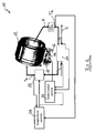
Figure 1 is a schematic layout of a tumble condensing dryer according to the invention; -
Figure 2 is a block diagram showing how the blower speed is adjusted according to the invention; -
Figure 3 is a diagram showing how the blower speed is adjusted by using the controlling scheme offigure 2 ; -
Figure 4 is an experimental diagram similar tofigure 3 ; and -
Figures 5 - 6 are diagrams showing how the air temperatures and blower speed change by using the method according to the present invention. - With reference to
Figure 1 , atumble dryer 10 comprises a rotatingdrum 12 actuated by anelectric motor 14 and adapted to contain a certain amount of clothes, aprocess fan 16 that drives air flow F and acooling fan 18 which drives a cooling air flow C along the outer side of a heat exchanger (condenser) 20. - In the example shown in
figure 1 thedrum 12, theprocess fan 16 and thecooling fan 18 are driven by thesame motor 14, but it is clear that they can be driven by using three different motors or two combined motors (for instance one for the drum and the other for the two fans). - A heater 22 (having one or more heating elements) is used to heat the process air upstream the
drum 12 according to a predefined number of power levels. - The dryer comprises a temperature sensor Ta that measures the temperature of the air after the
heater 22 and before entering thedrum 12, a temperature sensor Tb measuring the temperature of the clothes and a temperature sensor Tc that measures the output temperature of the cooling air flowing outside of theheat exchanger 20. - A common practice is to control only the temperature of the tumble dryer by feeding back the drum output temperature in the feedback control system. The drum output temperature (measured by temperature sensor Tb) is usually a good approximation of the clothes temperature and it therefore kept under control to avoid damages to the fabrics. The feedback is usually made trough hysteresis control i.e. the
heater 22 is switched on when the feedback temperature is below a predefined threshold and switched on when it is above a second predefined threshold. In this way the hysteresis control shows low performance when the temperature of theheater 22 is around the upper limit and it can cause oscillation of the clothes temperature. - A more advanced way to control the
heater 22 is through a PI (proportional-integral) control and PWM (Pulse Width Modulation). - With particular reference to the method according to the present invention, the efficiency of the
tumble dryer 10 is increased by controlling both the temperature of the clothes and the airflow in thedrum 12. The temperature is controlled by changing the power delivered by theheater 22 while the airflow F is controlled by changing the speed of thefan 16 by means of the variable speedelectric motor 14. - The temperature control is preferably carried out by means of a closed loop like PID controller which exploits the signals from the temperature sensors Ta and Tb of the
heater 22 and of the clothes respectively, while an adaptive strategy is employed to set the speed of thefan 16 in order to maximize the ratio between the water condensing rate and the power applied to the heating elements of theheater 22. - This control strategy requires the computation of the condensing rate or the assessment of a value related to the condensing rate, called also water removal rate. With the term "value related to" we mean any value which can be assessed through a direct measure or computated by means of a process software residing in a control process unit of the appliance which comprises a
temperature control unit 24 and amotor speed control 26. This value can be estimated in several ways by using temperature or external sensors like humidity sensors. - An efficient and preferred configuration of temperature sensors and method to estimate the condensing rate is explained in the following example with reference to
figure 1 . - Actually, the control of the air flow is a key issue for the efficiency of the overall drying process, by taking into account that the flow F of the air into the drum (internal loop) is related to the flow of the cooling air C (external loop). In fact, at the beginning of the drying operation it is advisable to decrease the air flow in order to increase the fabric temperature as fast as possible so that the evaporation can start soon. Subsequently, decreasing the speed of the
fan 16 or keeping it at a low level would cause an increment of the relative humidity of the air upstream theheat exchanger 20 but, at the same time, a decrement of the efficiency of theheat exchanger 20 mainly due to the lower heat exchange coefficient. - Conversely, increasing the speed of the
fan 16 is beneficial for the heat exchanger efficiency but the relative humidity of the air F entering in theheat exchanger 20 is reduced. Further, a too high rotation speed of the drum 12 (in the case thesame motor 14 is used for thefan 16 and for the drum 12) could make the clothes roll up into a ball and this has to be clearly avoided. - An adaptive strategy is therefore adopted to provide an effective solution. The initial fan speed is determined depending on the estimated load. We do not go onto detail of load estimation since this is an already known technique (one method is disclosed for instance in the already mentioned
US 2007/0251118 ). - Then, a "performance index" ϕ is defined as the average ratio between the water condensing rate and the power applied to the heating elements of the
heater 22, and a time period is defined in such a way that a rotation speed is applied for a fixed number of controlling PWM cycles and the performance index is subsequently evaluated for a predefined time control period. - Each time, the rotation speed is modified (increased or decreased) in the same way of the previous time when the previous modification has yielded an increment of the value of the performance index in the previous control period. Otherwise (namely, if the previous modification has yielded a decrement of the value of the performance index), the modification is done in the opposite direction with respect to the previous one. The control period is preferably of the order of 1 sec to allow continuous monitoring of the performance. This methodology is shown in
figure 2 . - The estimation of the value of the condensing rate can be done by taking into account that, since the relative humidity of the air in the
drum 12 is high, the difference of the temperature of the air flow F in the internal loop at the input of theheat exchanger 20 and that at the output is small (the water condensation being carried out at a constant temperature), while this difference is high for the cooling air C (external loop). Thus, by measuring the temperature at the output of the heat exchanger 20 (in the external loop) by means of the temperature sensor Tc, the difference of the cooling air temperature between the input and the output of theheat exchanger 20 can be measured (the temperature at the input is the room temperature which can be simply measured once by the same sensor Tc at the beginning of the drying process, or it can be measured by a specific temperature sensor Ti). By means of this measure the enthalpy difference between the air flowing inside and outside theheat exchanger 20 can be estimated. Thus, by knowing the ratio between the air flows F and C of the internal and external loops (which in the example shown infigure 1 depends on the shape of thefans 16 and 18) and by applying the principle of conservation of energy, the variation of enthalpy in the internal loop can be estimated. Indeed this variation depends only on the water condensing rate because, as mentioned before, the difference of the temperature is small and therefore negligible. As a consequence, this strategy could be easily used for adjusting the drum speed during the drying cycle. - To improve dryer efficiency is required to maximize the parameter ϕ:

where P water removed is the product of enthalpy of condensed water for its mass change rate. The control algorithm estimates the performance indicator ϕ in real-time, while the appliance is performing a drying cycle. - On the basis of trend of ϕ and in order to maximize the appliance efficiency the control can tune the fan speed and heaters duty cycle of the dryer.
- The output of ϕ control is also compensated according to the dryer phase (start, warm-up, drying, cooling down) to be sure to perform the best cycle optimization.
- For example, during a warm-up phase it is advisable to minimize as possible the time required to reach the regular working temperature of the appliance. The method according to the invention reduces automatically the fan speed during this phase and minimizes the temperature drop across the condenser 20 (reducing heat lost in the ambient).
- The graph of
Figure 4 shows the output of a control method according to the invention where a continuous tuning of the fan speed of dryer (upper line) is carried out by assessing the performance index ϕ (lower line) during a drying cycle. - Other experimental data of the above control strategy are shown in
Figures 5 and6 . - This experiment was carried out using a Whirlpool A Class dryer, equipped with a variable speed motor (BPM) and two heater coils (1500W +1500W).
-
Figure 5 shows values of temperature in different places of the tumble dryer and values of the moisture ratio Mr for an experiment with a load of 3 kg and a set-point temperature of 63 °C.Figure 6 shows a motor speed and temperature of the air flowing out of theheat exchanger 20 for an experiment with the same load and a set-point temperature as forfigure 5 . - With a control method according to the invention the energy saving is optimized on the different quantity of load, maximizing the benefits with small quantity of load.
Claims (8)
- A method for controlling the operation of a clothes dryer comprising a drying chamber (12) and an air flow system comprising a variable speed blower (14, 16) for forcing air through the drying chamber, characterized in that the method comprises assessing a value related to the water removal rate and adjusting the speed of the blower depending on said assessed value.
- A method according to claim 1, wherein said value is based on a ratio (ϕ) between the water condensing rate and the power of a heater (22) used to heat up the air flow (F) upstream the drying chamber (12).
- A method according to claim 1 or 2, wherein the speed of the blower (16) is changed depending on whether the previous change of speed in a previous control period has yielded an increase or decrease of said ratio (ϕ), in case of increase the change of speed being in the same direction, in case of decrease the change of speed being in the opposite direction.
- A method according to any of the preceding claims, for a clothes dryer having an heat exchanger (20) for cooling the air downstream the drying chamber (12) and upstream a heater (22), wherein the difference of temperature of cooling air (C) across the heat exchanger is measured, such difference being related to the water removal rate.
- A household tumble dryer comprising a rotatable drum (12) defining a drying chamber and an air flow system comprising a variable speed blower (14, 16) for forcing air through the drum (12), characterized in that it comprises a control unit (24, 26) adapted to assess a value related to water removal rate and to adjust the speed of the blower (16) depending on said assessed value.
- A household tumble dryer according to claim 5, wherein the control unit (24, 26) is adapted to adjust the speed of the blower (16) depending on a ratio between the water removal rate and the power delivered by a heater (22) which is placed upstream the drum (12).
- A household tumble dryer according to claim 5 or 6, including a heat exchanger (20) downstream the drum (12) for condensing water in the air flow (F), wherein said value is assessed by measuring the temperature increase of the cooling air across the heat exchanger (20).
- A household tumble dryer according to claim 5 or 6, wherein the control unit (24, 26) is adapted to process a signal from a weight sensor detecting the amount of condensed water.
Priority Applications (4)
| Application Number | Priority Date | Filing Date | Title |
|---|---|---|---|
| ES11174919.8T ES2443874T3 (en) | 2011-07-21 | 2011-07-21 | Method for controlling a clothes dryer and clothes dryer using such method |
| EP11174919.8A EP2549009B1 (en) | 2011-07-21 | 2011-07-21 | Method for controlling a clothes dryer and clothes dryer using such method |
| PL11174919T PL2549009T3 (en) | 2011-07-21 | 2011-07-21 | Method for controlling a clothes dryer and clothes dryer using such method |
| US13/550,741 US8919009B2 (en) | 2011-07-21 | 2012-07-17 | Method for controlling a clothes dryer and clothes dryer using such method |
Applications Claiming Priority (1)
| Application Number | Priority Date | Filing Date | Title |
|---|---|---|---|
| EP11174919.8A EP2549009B1 (en) | 2011-07-21 | 2011-07-21 | Method for controlling a clothes dryer and clothes dryer using such method |
Publications (2)
| Publication Number | Publication Date |
|---|---|
| EP2549009A1 true EP2549009A1 (en) | 2013-01-23 |
| EP2549009B1 EP2549009B1 (en) | 2013-12-25 |
Family
ID=45002551
Family Applications (1)
| Application Number | Title | Priority Date | Filing Date |
|---|---|---|---|
| EP11174919.8A Not-in-force EP2549009B1 (en) | 2011-07-21 | 2011-07-21 | Method for controlling a clothes dryer and clothes dryer using such method |
Country Status (4)
| Country | Link |
|---|---|
| US (1) | US8919009B2 (en) |
| EP (1) | EP2549009B1 (en) |
| ES (1) | ES2443874T3 (en) |
| PL (1) | PL2549009T3 (en) |
Cited By (4)
| Publication number | Priority date | Publication date | Assignee | Title |
|---|---|---|---|---|
| DE102012207741A1 (en) * | 2012-05-09 | 2013-11-14 | BSH Bosch und Siemens Hausgeräte GmbH | Method for operating a variable speed motor dryer during a heating phase and dryer suitable therefor |
| DE102012207742A1 (en) * | 2012-05-09 | 2013-11-14 | BSH Bosch und Siemens Hausgeräte GmbH | Method for operating a variable speed dryer of a drive motor and a suitable dryer for this purpose |
| EP3093599A1 (en) * | 2015-05-11 | 2016-11-16 | Coldbay AB | Method for controlling drying of wood |
| EP3216915A1 (en) * | 2016-03-10 | 2017-09-13 | Eco-Dryer Systems B.V. | Laundry dryer with optical sensors |
Families Citing this family (11)
| Publication number | Priority date | Publication date | Assignee | Title |
|---|---|---|---|---|
| PL2957671T3 (en) | 2009-06-29 | 2019-03-29 | Electrolux Home Products Corporation N.V. | Appliance for drying laundry |
| EP2270274B2 (en) | 2009-06-29 | 2022-01-12 | Electrolux Home Products Corporation N.V. | Appliance for drying laundry |
| EP2735642A1 (en) * | 2012-11-26 | 2014-05-28 | Electrolux Home Products Corporation N.V. | A method for controlling a laundry dryer with a variable drum rotation speed and a variable fan rotation speed |
| EP2738303A1 (en) * | 2012-11-28 | 2014-06-04 | Electrolux Home Products Corporation N.V. | A method for controlling a drying cycle of a laundry dryer |
| EP2789728B1 (en) * | 2013-04-08 | 2017-06-28 | Electrolux Appliances Aktiebolag | Method for controlling a motor of a laundry dryer |
| BR112016019573B1 (en) * | 2014-03-21 | 2022-02-22 | Electrolux Appliances Aktiebolag | LAUNDRY MACHINE |
| EP3192187B1 (en) * | 2014-09-08 | 2020-12-02 | Telefonaktiebolaget LM Ericsson (publ) | Scheduled transmission in cellular communications networks |
| DE102016000226A1 (en) * | 2016-01-14 | 2017-07-20 | Herbert Kannegiesser Gmbh | Device for mangling laundry |
| KR102602847B1 (en) * | 2016-06-03 | 2023-11-16 | 엘지전자 주식회사 | Clothes treating apparatus |
| US11028527B2 (en) | 2019-09-27 | 2021-06-08 | Whirlpool Corporation | Laundry treating appliance for drying laundry |
| KR20240035642A (en) * | 2021-09-01 | 2024-03-15 | 선전 로보락 이노베이션 테크놀러지 컴퍼니 리미티드 | Drying device and all-in-one washing and drying device |
Citations (7)
| Publication number | Priority date | Publication date | Assignee | Title |
|---|---|---|---|---|
| US4891892A (en) * | 1983-12-15 | 1990-01-09 | Narang Rajendra K | Clothes dryer and laundry system |
| US20040261286A1 (en) | 2003-06-27 | 2004-12-30 | Green Jeremy Michael | Clothes dryer apparatus and method |
| US20070025118A1 (en) | 2005-08-01 | 2007-02-01 | Silver David M | Method and apparatus for reducing visual aberrations |
| US20070151311A1 (en) * | 2005-12-30 | 2007-07-05 | Mcallister Karl D | Fabric revitalizing system |
| US20070251118A1 (en) | 2006-04-17 | 2007-11-01 | Lg Electronics Inc. | Dryer and method for controlling the same |
| US7525262B2 (en) * | 2005-01-12 | 2009-04-28 | Whirlpool Corporation | Automatic clothes dryer |
| US20110030428A1 (en) * | 2007-04-04 | 2011-02-10 | Dong Joo Han | Cloth treating apparatus |
Family Cites Families (6)
| Publication number | Priority date | Publication date | Assignee | Title |
|---|---|---|---|---|
| US3702030A (en) * | 1971-03-29 | 1972-11-07 | Whirlpool Co | Digital dryer control circuit |
| US4125946A (en) * | 1977-06-14 | 1978-11-21 | Melvin Prager | Apparatus for drying clothes using solar energy |
| US4231166A (en) * | 1979-10-09 | 1980-11-04 | General Electric Company | Automatic control for a clothes dryer |
| US4689896A (en) * | 1983-12-15 | 1987-09-01 | Narang Rajendra K | Clothes dryer and laundry system |
| US6745495B1 (en) * | 2003-06-27 | 2004-06-08 | General Electric Company | Clothes dryer apparatus and method |
| US8156660B2 (en) * | 2005-09-22 | 2012-04-17 | Whirlpool Corporation | Apparatus and method for drying clothes |
-
2011
- 2011-07-21 EP EP11174919.8A patent/EP2549009B1/en not_active Not-in-force
- 2011-07-21 PL PL11174919T patent/PL2549009T3/en unknown
- 2011-07-21 ES ES11174919.8T patent/ES2443874T3/en active Active
-
2012
- 2012-07-17 US US13/550,741 patent/US8919009B2/en active Active
Patent Citations (7)
| Publication number | Priority date | Publication date | Assignee | Title |
|---|---|---|---|---|
| US4891892A (en) * | 1983-12-15 | 1990-01-09 | Narang Rajendra K | Clothes dryer and laundry system |
| US20040261286A1 (en) | 2003-06-27 | 2004-12-30 | Green Jeremy Michael | Clothes dryer apparatus and method |
| US7525262B2 (en) * | 2005-01-12 | 2009-04-28 | Whirlpool Corporation | Automatic clothes dryer |
| US20070025118A1 (en) | 2005-08-01 | 2007-02-01 | Silver David M | Method and apparatus for reducing visual aberrations |
| US20070151311A1 (en) * | 2005-12-30 | 2007-07-05 | Mcallister Karl D | Fabric revitalizing system |
| US20070251118A1 (en) | 2006-04-17 | 2007-11-01 | Lg Electronics Inc. | Dryer and method for controlling the same |
| US20110030428A1 (en) * | 2007-04-04 | 2011-02-10 | Dong Joo Han | Cloth treating apparatus |
Cited By (6)
| Publication number | Priority date | Publication date | Assignee | Title |
|---|---|---|---|---|
| DE102012207741A1 (en) * | 2012-05-09 | 2013-11-14 | BSH Bosch und Siemens Hausgeräte GmbH | Method for operating a variable speed motor dryer during a heating phase and dryer suitable therefor |
| DE102012207742A1 (en) * | 2012-05-09 | 2013-11-14 | BSH Bosch und Siemens Hausgeräte GmbH | Method for operating a variable speed dryer of a drive motor and a suitable dryer for this purpose |
| WO2013167488A2 (en) | 2012-05-09 | 2013-11-14 | BSH Bosch und Siemens Hausgeräte GmbH | Method for operating a dryer at variable speed of a drive motor and dryer suitable therefor |
| WO2013167486A3 (en) * | 2012-05-09 | 2014-05-08 | BSH Bosch und Siemens Hausgeräte GmbH | Method for operating a dryer at variable motor speed during a heat-up phase and dryer suitable therefor |
| EP3093599A1 (en) * | 2015-05-11 | 2016-11-16 | Coldbay AB | Method for controlling drying of wood |
| EP3216915A1 (en) * | 2016-03-10 | 2017-09-13 | Eco-Dryer Systems B.V. | Laundry dryer with optical sensors |
Also Published As
| Publication number | Publication date |
|---|---|
| ES2443874T3 (en) | 2014-02-20 |
| US8919009B2 (en) | 2014-12-30 |
| PL2549009T3 (en) | 2014-03-31 |
| US20130019495A1 (en) | 2013-01-24 |
| EP2549009B1 (en) | 2013-12-25 |
Similar Documents
| Publication | Publication Date | Title |
|---|---|---|
| EP2549009B1 (en) | Method for controlling a clothes dryer and clothes dryer using such method | |
| EP2920356B1 (en) | Method of operating a heat pump laundry dryer and heat pump laundry dryer or heat pump washing machine having drying function | |
| EP3077588B1 (en) | A method for controlling a laundry drying machine of the type comprising a heat pump system and a corresponding laundry drying machine | |
| EP2690212B1 (en) | A method for controlling a laundry drying machine with heat pump system and laundry drying machine controlled by such method | |
| EP2977503B1 (en) | Laundry drying apparatus with heater unit having adjustable temperature thresholds | |
| CN104919109B (en) | Operate the method and heat pump cloth drying machine or the heat pump washing machine with drying function of heat pump cloth drying machine | |
| EP2832918B1 (en) | Laundry treatment apparatus and method for operating a laundry treatment apparatus | |
| CA2680529C (en) | Open-loop method for controlling power | |
| US20120084995A1 (en) | Energy efficient clothes dryer | |
| EP3425109B1 (en) | Method of operating a heat pump laundry dryer or heat pump washing machine having drying function | |
| CN107313226B (en) | Method for operating a laundry drying appliance and laundry drying appliance | |
| WO2014127667A1 (en) | Method for controlling expansion valve of heat pump clothes dryer | |
| EP2441880B1 (en) | Method for drying clothes in a drier and a moisture estimation control to obtain an automatic cycle termination | |
| EP2653603B1 (en) | Method for drying clothes in a household dryer | |
| EP2927367A1 (en) | Method of conducting a drying cycle in a laundry treating machine, laundry treating machine and electronic controller unit | |
| EP2716811A1 (en) | A method for controlling the rotation speed of a laundry drum in a laundry dryer and a corresponding laundry dryer | |
| EP2927363B1 (en) | Method of conducting a drying cycle in a laundry treating machine, laundry treating machine and electronic controller unit | |
| JP2018075368A (en) | Method for operating laundry dryer |
Legal Events
| Date | Code | Title | Description |
|---|---|---|---|
| PUAI | Public reference made under article 153(3) epc to a published international application that has entered the european phase |
Free format text: ORIGINAL CODE: 0009012 |
|
| AK | Designated contracting states |
Kind code of ref document: A1 Designated state(s): AL AT BE BG CH CY CZ DE DK EE ES FI FR GB GR HR HU IE IS IT LI LT LU LV MC MK MT NL NO PL PT RO RS SE SI SK SM TR |
|
| AX | Request for extension of the european patent |
Extension state: BA ME |
|
| 17P | Request for examination filed |
Effective date: 20130716 |
|
| RBV | Designated contracting states (corrected) |
Designated state(s): AL AT BE BG CH CY CZ DE DK EE ES FI FR GB GR HR HU IE IS IT LI LT LU LV MC MK MT NL NO PL PT RO RS SE SI SK SM TR |
|
| GRAP | Despatch of communication of intention to grant a patent |
Free format text: ORIGINAL CODE: EPIDOSNIGR1 |
|
| RIC1 | Information provided on ipc code assigned before grant |
Ipc: D06F 58/28 20060101AFI20130911BHEP Ipc: D06F 58/20 20060101ALI20130911BHEP |
|
| INTG | Intention to grant announced |
Effective date: 20130926 |
|
| GRAS | Grant fee paid |
Free format text: ORIGINAL CODE: EPIDOSNIGR3 |
|
| GRAA | (expected) grant |
Free format text: ORIGINAL CODE: 0009210 |
|
| AK | Designated contracting states |
Kind code of ref document: B1 Designated state(s): AL AT BE BG CH CY CZ DE DK EE ES FI FR GB GR HR HU IE IS IT LI LT LU LV MC MK MT NL NO PL PT RO RS SE SI SK SM TR |
|
| REG | Reference to a national code |
Ref country code: GB Ref legal event code: FG4D |
|
| REG | Reference to a national code |
Ref country code: CH Ref legal event code: EP |
|
| REG | Reference to a national code |
Ref country code: AT Ref legal event code: REF Ref document number: 646729 Country of ref document: AT Kind code of ref document: T Effective date: 20140115 |
|
| REG | Reference to a national code |
Ref country code: IE Ref legal event code: FG4D |
|
| REG | Reference to a national code |
Ref country code: DE Ref legal event code: R096 Ref document number: 602011004318 Country of ref document: DE Effective date: 20140213 |
|
| REG | Reference to a national code |
Ref country code: ES Ref legal event code: FG2A Ref document number: 2443874 Country of ref document: ES Kind code of ref document: T3 Effective date: 20140220 |
|
| PG25 | Lapsed in a contracting state [announced via postgrant information from national office to epo] |
Ref country code: NO Free format text: LAPSE BECAUSE OF FAILURE TO SUBMIT A TRANSLATION OF THE DESCRIPTION OR TO PAY THE FEE WITHIN THE PRESCRIBED TIME-LIMIT Effective date: 20140325 Ref country code: HR Free format text: LAPSE BECAUSE OF FAILURE TO SUBMIT A TRANSLATION OF THE DESCRIPTION OR TO PAY THE FEE WITHIN THE PRESCRIBED TIME-LIMIT Effective date: 20131225 Ref country code: SE Free format text: LAPSE BECAUSE OF FAILURE TO SUBMIT A TRANSLATION OF THE DESCRIPTION OR TO PAY THE FEE WITHIN THE PRESCRIBED TIME-LIMIT Effective date: 20131225 Ref country code: LT Free format text: LAPSE BECAUSE OF FAILURE TO SUBMIT A TRANSLATION OF THE DESCRIPTION OR TO PAY THE FEE WITHIN THE PRESCRIBED TIME-LIMIT Effective date: 20131225 Ref country code: FI Free format text: LAPSE BECAUSE OF FAILURE TO SUBMIT A TRANSLATION OF THE DESCRIPTION OR TO PAY THE FEE WITHIN THE PRESCRIBED TIME-LIMIT Effective date: 20131225 |
|
| REG | Reference to a national code |
Ref country code: NL Ref legal event code: VDEP Effective date: 20131225 |
|
| REG | Reference to a national code |
Ref country code: AT Ref legal event code: MK05 Ref document number: 646729 Country of ref document: AT Kind code of ref document: T Effective date: 20131225 |
|
| REG | Reference to a national code |
Ref country code: LT Ref legal event code: MG4D |
|
| PG25 | Lapsed in a contracting state [announced via postgrant information from national office to epo] |
Ref country code: LV Free format text: LAPSE BECAUSE OF FAILURE TO SUBMIT A TRANSLATION OF THE DESCRIPTION OR TO PAY THE FEE WITHIN THE PRESCRIBED TIME-LIMIT Effective date: 20131225 Ref country code: RS Free format text: LAPSE BECAUSE OF FAILURE TO SUBMIT A TRANSLATION OF THE DESCRIPTION OR TO PAY THE FEE WITHIN THE PRESCRIBED TIME-LIMIT Effective date: 20131225 |
|
| PG25 | Lapsed in a contracting state [announced via postgrant information from national office to epo] |
Ref country code: EE Free format text: LAPSE BECAUSE OF FAILURE TO SUBMIT A TRANSLATION OF THE DESCRIPTION OR TO PAY THE FEE WITHIN THE PRESCRIBED TIME-LIMIT Effective date: 20131225 Ref country code: IS Free format text: LAPSE BECAUSE OF FAILURE TO SUBMIT A TRANSLATION OF THE DESCRIPTION OR TO PAY THE FEE WITHIN THE PRESCRIBED TIME-LIMIT Effective date: 20140425 Ref country code: BE Free format text: LAPSE BECAUSE OF FAILURE TO SUBMIT A TRANSLATION OF THE DESCRIPTION OR TO PAY THE FEE WITHIN THE PRESCRIBED TIME-LIMIT Effective date: 20131225 |
|
| PG25 | Lapsed in a contracting state [announced via postgrant information from national office to epo] |
Ref country code: RO Free format text: LAPSE BECAUSE OF FAILURE TO SUBMIT A TRANSLATION OF THE DESCRIPTION OR TO PAY THE FEE WITHIN THE PRESCRIBED TIME-LIMIT Effective date: 20131225 Ref country code: NL Free format text: LAPSE BECAUSE OF FAILURE TO SUBMIT A TRANSLATION OF THE DESCRIPTION OR TO PAY THE FEE WITHIN THE PRESCRIBED TIME-LIMIT Effective date: 20131225 Ref country code: PT Free format text: LAPSE BECAUSE OF FAILURE TO SUBMIT A TRANSLATION OF THE DESCRIPTION OR TO PAY THE FEE WITHIN THE PRESCRIBED TIME-LIMIT Effective date: 20140428 Ref country code: AT Free format text: LAPSE BECAUSE OF FAILURE TO SUBMIT A TRANSLATION OF THE DESCRIPTION OR TO PAY THE FEE WITHIN THE PRESCRIBED TIME-LIMIT Effective date: 20131225 Ref country code: CZ Free format text: LAPSE BECAUSE OF FAILURE TO SUBMIT A TRANSLATION OF THE DESCRIPTION OR TO PAY THE FEE WITHIN THE PRESCRIBED TIME-LIMIT Effective date: 20131225 Ref country code: CY Free format text: LAPSE BECAUSE OF FAILURE TO SUBMIT A TRANSLATION OF THE DESCRIPTION OR TO PAY THE FEE WITHIN THE PRESCRIBED TIME-LIMIT Effective date: 20131225 Ref country code: SK Free format text: LAPSE BECAUSE OF FAILURE TO SUBMIT A TRANSLATION OF THE DESCRIPTION OR TO PAY THE FEE WITHIN THE PRESCRIBED TIME-LIMIT Effective date: 20131225 |
|
| REG | Reference to a national code |
Ref country code: DE Ref legal event code: R097 Ref document number: 602011004318 Country of ref document: DE |
|
| PG25 | Lapsed in a contracting state [announced via postgrant information from national office to epo] |
Ref country code: DK Free format text: LAPSE BECAUSE OF FAILURE TO SUBMIT A TRANSLATION OF THE DESCRIPTION OR TO PAY THE FEE WITHIN THE PRESCRIBED TIME-LIMIT Effective date: 20131225 |
|
| PLBE | No opposition filed within time limit |
Free format text: ORIGINAL CODE: 0009261 |
|
| STAA | Information on the status of an ep patent application or granted ep patent |
Free format text: STATUS: NO OPPOSITION FILED WITHIN TIME LIMIT |
|
| 26N | No opposition filed |
Effective date: 20140926 |
|
| REG | Reference to a national code |
Ref country code: DE Ref legal event code: R097 Ref document number: 602011004318 Country of ref document: DE Effective date: 20140926 |
|
| PG25 | Lapsed in a contracting state [announced via postgrant information from national office to epo] |
Ref country code: LU Free format text: LAPSE BECAUSE OF FAILURE TO SUBMIT A TRANSLATION OF THE DESCRIPTION OR TO PAY THE FEE WITHIN THE PRESCRIBED TIME-LIMIT Effective date: 20140721 |
|
| REG | Reference to a national code |
Ref country code: CH Ref legal event code: PL |
|
| REG | Reference to a national code |
Ref country code: IE Ref legal event code: MM4A |
|
| PG25 | Lapsed in a contracting state [announced via postgrant information from national office to epo] |
Ref country code: CH Free format text: LAPSE BECAUSE OF NON-PAYMENT OF DUE FEES Effective date: 20140731 Ref country code: LI Free format text: LAPSE BECAUSE OF NON-PAYMENT OF DUE FEES Effective date: 20140731 |
|
| PG25 | Lapsed in a contracting state [announced via postgrant information from national office to epo] |
Ref country code: SI Free format text: LAPSE BECAUSE OF FAILURE TO SUBMIT A TRANSLATION OF THE DESCRIPTION OR TO PAY THE FEE WITHIN THE PRESCRIBED TIME-LIMIT Effective date: 20131225 |
|
| PG25 | Lapsed in a contracting state [announced via postgrant information from national office to epo] |
Ref country code: IE Free format text: LAPSE BECAUSE OF NON-PAYMENT OF DUE FEES Effective date: 20140721 |
|
| PG25 | Lapsed in a contracting state [announced via postgrant information from national office to epo] |
Ref country code: MC Free format text: LAPSE BECAUSE OF FAILURE TO SUBMIT A TRANSLATION OF THE DESCRIPTION OR TO PAY THE FEE WITHIN THE PRESCRIBED TIME-LIMIT Effective date: 20131225 Ref country code: SM Free format text: LAPSE BECAUSE OF FAILURE TO SUBMIT A TRANSLATION OF THE DESCRIPTION OR TO PAY THE FEE WITHIN THE PRESCRIBED TIME-LIMIT Effective date: 20131225 |
|
| REG | Reference to a national code |
Ref country code: FR Ref legal event code: PLFP Year of fee payment: 6 |
|
| PG25 | Lapsed in a contracting state [announced via postgrant information from national office to epo] |
Ref country code: MT Free format text: LAPSE BECAUSE OF FAILURE TO SUBMIT A TRANSLATION OF THE DESCRIPTION OR TO PAY THE FEE WITHIN THE PRESCRIBED TIME-LIMIT Effective date: 20131225 Ref country code: BG Free format text: LAPSE BECAUSE OF FAILURE TO SUBMIT A TRANSLATION OF THE DESCRIPTION OR TO PAY THE FEE WITHIN THE PRESCRIBED TIME-LIMIT Effective date: 20131225 Ref country code: GR Free format text: LAPSE BECAUSE OF FAILURE TO SUBMIT A TRANSLATION OF THE DESCRIPTION OR TO PAY THE FEE WITHIN THE PRESCRIBED TIME-LIMIT Effective date: 20140326 |
|
| PG25 | Lapsed in a contracting state [announced via postgrant information from national office to epo] |
Ref country code: TR Free format text: LAPSE BECAUSE OF FAILURE TO SUBMIT A TRANSLATION OF THE DESCRIPTION OR TO PAY THE FEE WITHIN THE PRESCRIBED TIME-LIMIT Effective date: 20131225 Ref country code: HU Free format text: LAPSE BECAUSE OF FAILURE TO SUBMIT A TRANSLATION OF THE DESCRIPTION OR TO PAY THE FEE WITHIN THE PRESCRIBED TIME-LIMIT; INVALID AB INITIO Effective date: 20110721 |
|
| PGFP | Annual fee paid to national office [announced via postgrant information from national office to epo] |
Ref country code: ES Payment date: 20160613 Year of fee payment: 6 |
|
| REG | Reference to a national code |
Ref country code: FR Ref legal event code: PLFP Year of fee payment: 7 |
|
| PGFP | Annual fee paid to national office [announced via postgrant information from national office to epo] |
Ref country code: PL Payment date: 20170620 Year of fee payment: 7 |
|
| REG | Reference to a national code |
Ref country code: FR Ref legal event code: PLFP Year of fee payment: 8 |
|
| PG25 | Lapsed in a contracting state [announced via postgrant information from national office to epo] |
Ref country code: MK Free format text: LAPSE BECAUSE OF FAILURE TO SUBMIT A TRANSLATION OF THE DESCRIPTION OR TO PAY THE FEE WITHIN THE PRESCRIBED TIME-LIMIT Effective date: 20131225 |
|
| PGFP | Annual fee paid to national office [announced via postgrant information from national office to epo] |
Ref country code: FR Payment date: 20180612 Year of fee payment: 8 |
|
| REG | Reference to a national code |
Ref country code: ES Ref legal event code: FD2A Effective date: 20181026 |
|
| PG25 | Lapsed in a contracting state [announced via postgrant information from national office to epo] |
Ref country code: AL Free format text: LAPSE BECAUSE OF FAILURE TO SUBMIT A TRANSLATION OF THE DESCRIPTION OR TO PAY THE FEE WITHIN THE PRESCRIBED TIME-LIMIT Effective date: 20131225 |
|
| PGFP | Annual fee paid to national office [announced via postgrant information from national office to epo] |
Ref country code: IT Payment date: 20180713 Year of fee payment: 8 Ref country code: DE Payment date: 20180710 Year of fee payment: 8 |
|
| PGFP | Annual fee paid to national office [announced via postgrant information from national office to epo] |
Ref country code: GB Payment date: 20180718 Year of fee payment: 8 |
|
| PG25 | Lapsed in a contracting state [announced via postgrant information from national office to epo] |
Ref country code: ES Free format text: LAPSE BECAUSE OF NON-PAYMENT OF DUE FEES Effective date: 20170722 |
|
| REG | Reference to a national code |
Ref country code: DE Ref legal event code: R079 Ref document number: 602011004318 Country of ref document: DE Free format text: PREVIOUS MAIN CLASS: D06F0058280000 Ipc: D06F0058300000 |
|
| REG | Reference to a national code |
Ref country code: DE Ref legal event code: R119 Ref document number: 602011004318 Country of ref document: DE |
|
| PG25 | Lapsed in a contracting state [announced via postgrant information from national office to epo] |
Ref country code: PL Free format text: LAPSE BECAUSE OF NON-PAYMENT OF DUE FEES Effective date: 20180721 |
|
| GBPC | Gb: european patent ceased through non-payment of renewal fee |
Effective date: 20190721 |
|
| PG25 | Lapsed in a contracting state [announced via postgrant information from national office to epo] |
Ref country code: DE Free format text: LAPSE BECAUSE OF NON-PAYMENT OF DUE FEES Effective date: 20200201 Ref country code: GB Free format text: LAPSE BECAUSE OF NON-PAYMENT OF DUE FEES Effective date: 20190721 |
|
| PG25 | Lapsed in a contracting state [announced via postgrant information from national office to epo] |
Ref country code: FR Free format text: LAPSE BECAUSE OF NON-PAYMENT OF DUE FEES Effective date: 20190731 |
|
| PG25 | Lapsed in a contracting state [announced via postgrant information from national office to epo] |
Ref country code: IT Free format text: LAPSE BECAUSE OF NON-PAYMENT OF DUE FEES Effective date: 20190721 |