EP2548521A2 - Endoscopic clip applier and method - Google Patents
Endoscopic clip applier and method Download PDFInfo
- Publication number
- EP2548521A2 EP2548521A2 EP12004149A EP12004149A EP2548521A2 EP 2548521 A2 EP2548521 A2 EP 2548521A2 EP 12004149 A EP12004149 A EP 12004149A EP 12004149 A EP12004149 A EP 12004149A EP 2548521 A2 EP2548521 A2 EP 2548521A2
- Authority
- EP
- European Patent Office
- Prior art keywords
- assembly
- clip
- jaw
- distal end
- clips
- Prior art date
- Legal status (The legal status is an assumption and is not a legal conclusion. Google has not performed a legal analysis and makes no representation as to the accuracy of the status listed.)
- Granted
Links
Images


Classifications
-
- A—HUMAN NECESSITIES
- A61—MEDICAL OR VETERINARY SCIENCE; HYGIENE
- A61B—DIAGNOSIS; SURGERY; IDENTIFICATION
- A61B17/00—Surgical instruments, devices or methods, e.g. tourniquets
- A61B17/12—Surgical instruments, devices or methods, e.g. tourniquets for ligaturing or otherwise compressing tubular parts of the body, e.g. blood vessels, umbilical cord
- A61B17/128—Surgical instruments, devices or methods, e.g. tourniquets for ligaturing or otherwise compressing tubular parts of the body, e.g. blood vessels, umbilical cord for applying or removing clamps or clips
- A61B17/1285—Surgical instruments, devices or methods, e.g. tourniquets for ligaturing or otherwise compressing tubular parts of the body, e.g. blood vessels, umbilical cord for applying or removing clamps or clips for minimally invasive surgery
Definitions
- This invention generally relates to an applier for surgical clips. More particularly, this invention relates to a ligating clip applier capable of sequentially delivering a number of clips stored in a clip channel.
- Laparoscopic, endoscopic, and other minimally invasive surgical techniques enable surgeons to perform fairly complicated procedures through relatively small entry points in the body.
- the term “laparoscopic” refers to surgical procedures performed on the interior of the abdomen, while the term “endoscopic” refers more generally to procedures performed in any portion of the body.
- Endoscopic surgery involves the use of an endoscope, which is an instrument permitting the visual inspection and magnification of a body cavity.
- the endoscope is inserted into a body cavity through a cannula extending through a hole in the soft tissue protecting the body cavity.
- the hole is made with a trocar, which includes a cutting instrument slidably and removably disposed within a trocar cannula.
- the cutting instrument can be withdrawn from the trocar cannula.
- a surgeon can then perform diagnostic and/or therapeutic procedures at the surgical site with the aid of specialized medical instruments adapted to fit through the trocar cannula and additional trocar cannulas providing openings into the desired body cavity.
- minimally invasive surgical techniques Some known advantages of minimally invasive surgical techniques include reduced trauma to the patient, reduced likelihood of infection at the surgical site, and lower overall medical costs. Accordingly, minimally invasive surgical techniques are being applied to an increasingly wider array of medical procedures.
- Many surgical procedures require body vessels to be ligated during the surgical process.
- many surgical procedures require cutting blood vessels (e. g. , veins or arteries), and these blood vessels may require ligation to reduce bleeding.
- a surgeon may wish to ligate the vessel temporarily to reduce blood flow to the surgical site during the surgical procedure.
- a surgeon may wish to permanently ligate a vessel.
- Vessel ligation may be performed by closing the vessel with a ligating clip, or by suturing the vessel with surgical thread.
- Performing vessel ligation using surgical thread requires complex manipulations of the needle and suture material to form the knots required to secure the vessel.
- Such complex manipulations are timeconsuming and difficult to perform, particularly in endoscopic surgical procedures, which are characterized by limited space and visibility.
- ligating clips are relatively easy and quick to apply. Accordingly, the use of ligating clips in endoscopic surgical procedures has grown dramatically.
- Ligating clips may be classified according to their geometric configuration as either symmetric clips or asymmetric clips, and according to the material from which they are manufactured.
- Symmetric clips are generally"U"or"V"shaped metallic clips that are substantially symmetrical about a central, longitudinal axis extending between the legs of the clip.
- asymmetric clips lack an axis of symmetry.
- U. S. Patent No. 4,834, 096 to Oh et al. describes a polymeric, asymmetric surgical clip in which a first leg member includes a lip that mates with the second leg member to lock the clip in place.
- Asymmetric clips have certain advantages over symmetric clips.
- asymmetric clips are formed from polymeric materials
- the mouths of asymmetric clips can be opened wider than the mouths of symmetric clips. This allows a surgeon to position the clip about the desired vessel with greater accuracy.
- a clip of the type described in U. S. Patent No. 4,834, 096 can be repositioned before locking the clip on the vessel, a process referred to as"approximating"the clip, or to be removed from the vessel.
- Surgical clip appliers adapted for endoscopic surgical techniques include a shaft adapted to be inserted through an endoscopic cannula to access a surgical site in a body cavity and a jaw assembly disposed at the distal end of the shaft for retaining a surgical clip.
- the clip is positioned over the desired vessel and the jaw is actuated, typically using a mechanism disposed in the handle of the device, to close the clip about the vessel.
- Multiple clip applier systems have been developed that enable surgeons to deliver multiple symmetric surgical clips to an endoscopic surgical site.
- these systems provide a surgical clip channel within the shaft of the device and a mechanism for delivering the surgical clips through the shaft to the jaw assembly.
- U. S. Patent Nos. 5,100, 420 and 5,645, 551 to Green et al. describe a device for delivering and applying multiple surgical clips to an endoscopic surgical site.
- U. S. Patent No. Re 35,525 to Stefanchik et al. aims to provide an endoscopic multiple ligating clip applier with a venting system.
- the jaws of the applier which are typically used to close a clip around a vessel, may exert unequal pressure on the clip, resulting in a"scissoring"effect and damage to the vessel.
- the clip may not be properly oriented when it is placed within the jaws or may slip out of alignment during application. This may result in the loss or misapplication of the clip.
- the applier may jam or may simply fail to deploy a clip.
- symmetric clips can be retained in clip jaws by holding opposing surfaces of the clip's legs in opposing channels.
- asymmetric clips cannot easily be retained in opposing channels because the clip's legs deform when the clip is closed.
- the opposing legs of the clip apply substantially even pressure to the opposing sides of the vessel.
- the opposing legs of an asymmetric clip may apply varying pressure to opposing sides of a vessel when the asymmetric clip is closed.
- asymmetric clips of the type described in U. S. Patent No. 4,834, 096 function best when force is applied at or near the distal ends of the clip legs. Still further, asymmetric clips of the type described in U. S. Patent No. 4,834, 096 may need to be placed under compression to be retained in the clip channel. Thus, conventional clip advancing mechanisms designed for symmetric clips may not reliably advance asymmetric clips. In addition, conventional clip advancing mechanisms designed for symmetric clips may not provide the ability to approximate a clip.
- an endoscopic clip applier adapted to retain a plurality of asymmetric ligating clips in a clip channel contained within a shaft assembly, and including a jaw assembly for applying an asymmetric clip.
- the jaw assembly is connected to the distal end of the clip channel, and a handle assembly is connected to a proximal end of the clip channel.
- a feeder bar mounted adjacent the clip channel is moveable between a proximal position and a distal position to advance clips in the clip applier and to feed a clip from the clip channel to the jaw assembly.
- the shaft assembly is moveable between a proximal position and a distal position, and includes cam surfaces for closing the jaw assembly when the shaft assembly is moved in a distal direction.
- a trigger on the handle assembly actuates the feeder bar to advance clips in the clip channel and advances the shaft assembly to close the jaw assembly.
- the shaft assembly may be rotated about its longitudinal axis.
- the invention provides an endoscopic surgical applier having a jaw assembly adapted to establish four separate points of contact with a ligating clip to stabilize the clip in the jaw assembly. Accordingly, the invention provides an endoscopic surgical clip applier that comprises a shaft assembly having a distal end adapted for insertion through a cannula into a body cavity and a clip channel disposed within the shaft assembly for retaining a plurality of clips.
- a jaw assembly extends from the distal end of the shaft assembly and includes a first jaw member having a first jaw arm for engaging a first portion of a ligating clip and an opposing second jaw arm for engaging a second portion of a ligating clip, the first and second jaw arms each comprising a cam surface, and a second jaw member having a third jaw arm for engaging a third portion of a ligating clip and an opposing fourth jaw arm for engaging a fourth portion of a ligating clip, the third and fourth jaw arms each comprising a cam surface.
- An actuation assembly advances a clip from the clip channel to the jaw assembly.
- the invention provides an endoscopic clip applier in which cam surfaces on the exterior shaft assembly cooperate with corresponding cam surfaces on the jaw assembly to close the jaw assembly.
- the invention provides an endoscopic surgical clip applier that comprises an exterior shaft assembly having a proximal end and a distal end adapted for insertion through a cannula into a body cavity and having a plurality of cam surfaces formed at the distal end.
- a jaw assembly extends from the distal end of the shaft assembly and includes a first jaw member having a first jaw arm for engaging a first portion of a ligating clip and an opposing second jaw arm for engaging a second portion of a ligating clip.
- the first and second jaw arms each comprise a cam surface, as do the third and fourth jaw arms.
- a clip channel Contained within the exterior shaft assembly are a clip channel adapted to hold a plurality of clips, and a feeder bar for feeding clips from the clip channel to the jaw assembly.
- An actuation assembly for closing the jaw assembly induces relative motion between the exterior shaft assembly and the jaw assembly so that contact between the cam surfaces closes the jaw assembly.
- an endoscopic surgical clip applier that allows a user to approximate a surgical clip before locking the clip on a vessel.
- an endoscopic surgical clip applier comprises an exterior shaft assembly having a proximal end and a distal end adapted for insertion through a cannula into a body cavity.
- a clip channel is disposed within the exterior shaft assembly for holding a plurality of clips, and a jaw assembly is connected to the distal end of the clip channel.
- An actuation assembly includes a trigger for implementing an actuation stroke having a first portion for advancing a clip from the clip channel into the jaw assembly and a second portion for closing the jaw assembly.
- a ratchet assembly is connected to the trigger, wherein the ratchet assembly precludes reverse motion of the trigger during the first portion of the actuation stroke, but allows reverse motion of the trigger during the second portion of the actuation stroke.
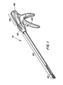
- an exemplary embodiment of an endoscopic clip applier 10 in accordance with the present invention includes a shaft assembly 20 having a jaw assembly 90 disposed at a distal end and a handle assembly 140 disposed at a proximal end.
- the handle assembly 140 includes a stationary grip 142 and a moveable trigger 144 for actuating the clip applier 10.
- the jaw assembly 90 may be positioned inside a body cavity, for example by passing the shaft assembly 20 through an endoscopic cannula, to apply a ligating clip to a body vessel.
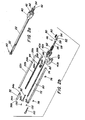
- Figure 2a is a perspective view and Figures 2b and 2c are exploded assembly views of an exemplary embodiment of shaft assembly 20 and jaw assembly 90.
- Shaft assembly 20 includes a cylindrical outer shaft member 22, which may be formed from two semi-cylindrical outer shaft members 22a and 22b, respectively. It will be appreciated that outer shaft member 22 may be formed from a single tubular member, or may be of a rectangular or polygonal cross-section. Outer shaft member 22 includes a proximal flange 24, indicated by proximal flanges 24a, 24b extending from the cylindrical surface of shaft members 22a and 22b. Outer shaft member further includes pin slots 28a, 28b formed in the cylindrical surface. In addition, the cylindrical surface of outer shaft members 22a, 22b include opposing channels 26a, 26b that define opposing slots when shaft member 22 is assembled. Outer shaft 22 may be formed from a suitably rigid material, e. g. , a suitable polymer or metal.
- shaft 22 may taper from a cylindrical cross-section to a substantially rectangular cross-section.
- a collar 32 ( Figure 18 ) has keys 34a, 34b that interlock with key slots 30a, 30b for connecting the collar 32 to outer shaft member 22.
- Collar 32 preferably is substantially rectangular in cross-section and includes four cam surfaces 38a, 38b, 38c, 38d and opposing keys 36a, 36b at its distal end.
- Collar 32 may be formed from suitably rigid material, e. g. , a suitable polymer or metal.
- a clip feed assembly 70 is disposed within the shaft 22 and collar 32.
- Clip feed assembly 70 includes a channel 72 for housing clips 78 and feeder bar 80 that is moveable along the longitudinal axis of shaft 22 for moving clips disposed in channel 72 toward the distal end of the applier 10.
- Channel 72 includes a pin hole 74 near the proximal end and a plurality of tabs 76 near its base.
- Channel 72 may be formed from suitably rigid material, e. g. , a suitable polymer or metal.
- Feeder bar 80 includes a pin slot 82 and a plurality of tabs 84 which act as clip advancing elements to move the clips 78 in channel 72 toward the distal end of the applier 10.
- Each tab 84 may be formed by stamping or cutting a portion of the body of the feeder bar 80. The tab 84 remains attached to the body of the feeder bar 80 at the proximal end of the tab 84.
- Each tab 84 may be bent or otherwise directed toward the interior of the clip channel 72.
- the tabs 84 may have a substantially uniform length, which may be determined by the length and geometry of the endoscopic clip, and by the rigidity of the material from which the feeder bar 80 is manufactured.
- the tabs 84 may be located along either the top or bottom (or both) edges of the side of the clip channel.
- Feeder bar 82 may be formed from suitably rigid material, e. g. , a suitable polymer or metal.
- Shaft assembly 20 further includes a yoke 50, a portion of which is disposed within the handle assembly 140, for translating longitudinal motion to feeder bar 80 and outer shaft 22.
- Feeder bar 80 includes a tab 86 that rests adjacent an interior distal edge 57 of yoke 50 ( Fig. 15c ).
- a portion of the yoke body 56 extends along a portion of the length of feeder bar 80 and has a slot 58 that aligns with pin slot 82 when yoke 50 is connected to feeder bar 80.
- Yoke 50 further includes a flange 52 and pin 54 on its proximal end.
- Yoke 50 may be formed from suitably rigid material, e. g. , a suitable polymer or metal.
- a feeder spring 60 is positioned within the body 56 of yoke 50 for biasing the feeder bar toward the distal end of yoke 50.
- a tube spring 62 is positioned between flange 52 and a flange 42 on knob 40 for biasing the yoke 50 toward the proximal end of the shaft assembly.
- a knob spring 64 is disposed within knob 40 and biases the outer shaft 22 in a proximal direction.
- a jaw assembly 90 is connected to the distal end of clip channel 72.
- Jaw assembly 90 includes a first jaw member 92 having a first leg 94 and a second leg 99 connected by a bridge member 104.
- First leg 94 includes a first cam surface 96 and a first jaw arm 98
- second leg 99 includes a second cam surface 100 and a second jaw arm 102.
- Bridge member 104 includes a slot 106 for receiving a conventional fastener (e. g. , rivets, pins, screws, tabs, etc. ) to connect first jaw member 92 to channel 72.
- Jaw assembly 90 further includes a second jaw member 110 having a third leg 112 and a fourth leg 118 connected by a bridge member 124.
- Third leg 112 includes a third cam surface 114 and a third jaw arm 116
- fourth leg 118 includes a fourth cam surface 120 and a fourth jaw arm 122
- Bridge member 124 includes a slot 126 for receiving a conventional fastener (e. g. , rivets, pins, screws, tabs, etc. ) to connect second jaw member 110 to channel 72.
- Jaw assembly 90 further includes a first guide 130 adapted to clip over first jaw arm 98 and third jaw arm 116 and a second guide 132 adapted to clip over second jaw arm 102 and fourth jaw arm 122.
- Jaw assembly 90 may be formed from suitably rigid material, e. g. , a suitable polymer or metal.
- Figures 3a and 3b are cross-sectional views of an assembled shaft assembly of a clip applier in accordance with the present invention.
- the jaw assembly 90, clip feed assembly 70, and yoke 50 are connected as described herein and extend through outer shaft 22.
- Knob 40 is mounted to the exterior of shaft 22 and secured using conventional fasteners (e. g. , pins, rivets, screws, adhesives, etc.).
- a pin 46 extending through knob 40 and through pin hole 74 in channel 72 retains channel 72 in a fixed position with respect to knob 40.
- Figure 3a illustrates a clip channel 72 having a single clip 78, but it will be appreciated that the clip channel 72 may be filled with a plurality (e. g. , 2-100) clips.
- the diameter of shaft 22 is determined by the diameter of the cannula through which the shaft 22 must pass to enter a body cavity. Many existing surgical procedures use a cannula having an inner diameter measuring approximately 10 millimeters. Accordingly, in one embodiment of the invention, the shaft 22 has an outer diameter slightly less than 10 millimeters. In an alternate embodiment, the shaft 22 may be dimensioned to fit within a cannula having a diameter of 5 millimeters. It will be appreciated, however, that the diameter of the shaft 22 is not critical to the invention; any other diameter may be used as desired.
- a handle assembly 140 includes a fixed grip 142, which may be manufactured in two substantially symmetrical parts 142a, 142b.
- a trigger 144 is pivotally mounted to fixed grip 142 about a pivot point 146.
- Trigger 144 includes a grooved claw 148 that impinges on flange 52 to translate the rotary motion of trigger 144 about pivot point 146 to linear motion of yoke 50 relative to fixed grip 142 in the distal direction. Grooved claw 148 also receives the pin 54 of yoke 50. This arrangement enables a user to force yoke 50 in a proximal direction if necessary, which provides a safety feature.
- Fixed grip 142 further includes a rim 150 that secures the flange 42 of knob 40, such that knob 40 and channel 72 are maintained in a substantially fixed longitudinal position relative to fixed grip 142.
- the entire shaft assembly 20 is rotatable about its longitudinal axis, and knob 40 includes fins 44 that facilitate rotating the shaft assembly 20.
- a ratchet key 152 extends from the rear of trigger 144 and contacts ratchet guide 154 to inhibit backward motion of trigger 144 through a portion of the actuation stroke.
- the toothed surface portion of ratchet guide 154 corresponds to the range of motion trigger claw 148 covers while the feeder bar 80 is moved forward to advance the clips in clip channel 72 (i. e. , the feed stroke).
- the smooth surface portion of ratchet guide 154 preferably corresponds to the range of motion trigger claw 148 covers during the portion of the actuation stroke that closes the jaw assembly 90.
- the transition of the ratchet key 152 from the ratchet surface portion to the smooth surface portion provides the user with tactile feedback indicating that the feed stroke is complete and a clip has been fed to the jaw assembly 90.
- the smooth surface portion permits a user to approximate a clip.
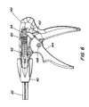
- Figure 6 is a partial cut-away, side view of the proximal end of clip applier 10 with the device in an unactuated state.
- yoke 50 is biased to its most proximal position by tube spring 62.
- the jaws 90 are partially open, as depicted in Figure 1 .
- Trigger 144 and yoke 50 in combination, may be considered an actuation assembly for actuating the clip feed assembly 70 and the jaw assembly 90.
- Figure 7 is a side cut-away view of the proximal end of clip applier 10 with the device in a partially actuated state. Forward motion of yoke 50 places tube spring 62 under compression. In one embodiment, the spring coefficient of feeder spring 60 is higher than the amount of force required to advance the feeder bar 80.
- the feeder spring 60 effectively functions as a solid piece of material during the feed stroke.
- the first portion of the stroke of trigger 144 is a feed stroke that advances yoke 50 and feeder bar 80 relative to the fixed channel 72.
- the tabs 84 engage the clips 78 in channel 72 and advance the clips 78 toward the distal end of applier 10.
- the most distal clip 78 is fed into the jaw assembly 90.
- Figures 8-10 are partial cutaway views of the clip feeder assembly illustrating the advance of a position to the most distal during the feed stroke. For clarity of illustration, the distal end of feed bar 80 has been cut-away in Figures 8-10 .
- Figure 8 illustrates the beginning of a feed stroke, in which the tab 84 of feeder bar 80 is brought into contact with a boss 79a of clip 78 disposed in channel 72.
- FIG 9 further actuation of trigger 144 moves the feeder bar 80 in a distal direction, which advances clip 78 toward the distal end of channel 72.
- the feeder bar 80 has advanced clip 78 to the most distal position in channel 72.
- Figures 8-10 illustrate the advance of a single clip 78 toward the distal end of applier 10, but it will be appreciated that the clip channel may include a plurality (e. g. , 2-100) of clips, each of which is advanced by a tab 84 of feeder bar 80.
- channel 72 holds twenty (20) clips.
- the feeder bar 80 and the clip channel 72 include structure particularly adapted to feed the most distal clip 78 into the jaw assembly 90.
- the distal end of channel 72 and feeder bar 80 include structural features adapted to feed the most distal clip into the jaw assembly 90.
- the distal end of feeder bar 80 includes a feeder tab 88 adapted to contact the central, rear portion of the most distal clip to push the clip into the jaw assembly 90.
- feeder bar 80 includes a foot member 89 that rotates the rear of the most distal clip during the return stroke so the rear portion of the clip is positioned to contact feeder tab 88.
- the interior surfaces of the jaw assembly that receive the clips are of substantially the same width as the channel 72 to provide a smooth transition between the channel 72 and the jaw assembly 90.
- the distal end of channel 72 includes a tab 71 that catches the boss on the most distal clip 78 when the foot member 89 of feeder bar 80 rotates the clip during the return stroke, thereby limiting the rotation of the clip.
- opposing ribs 73a, 73b facilitate centering the rear of the most distal clip (in the lateral direction) so the rear portion of the clip is positioned to contact feeder tab 88.
- the distal end of channel 72 further includes upper and lower tabs 77a, 77b to provide a surface that facilitates the transfer of the clip 78 into the jaw assembly 90.
- FIG. 20 also provides a view of tabs 76 that inhibit clips 78 from sliding in a proximal direction during the return stroke of feeder bar 80, and of tabs 79a-79d for securing a jaw member to clip channel 72.
- the applier 10 is configured such that further actuation of the trigger functions to open a clip 78 disposed in the jaw assembly 90.
- the clips 78 are fed through channel 72 in a compressed configuration, which reduces the required diameter of the shaft assembly 22.
- the most distal clip 78 is fed into the jaw assembly 90 in the same compressed configuration.
- hooks 98,102, 116,122 limit the forward motion of clip 78 in jaw assembly 90. Therefore, when further pressure is applied to the rear of clip 78 via the feeder tab 88 of feeder bar 80, the force is translated through the legs of clip 78, which causes the jaw assembly 90 (and the clip 78 contained therein) to open wider.
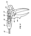
- FIG. 11 is a side cut-away view of the proximal end of clip applier 10 with the device in a fully actuated state.
- Pin 46 is always in clearance with the channel 26 in shaft member 22.
- a rib 149 in handle body 142 limits the forward motion of the claw 148 portion of trigger 144, and hence limits the forward motion of yoke 50.
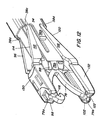
- Figures 12-14 are perspective views of distal end of applier 10 illustrating the jaw assembly 90 while it is being closed. Referring first to Figure 12 , following completion of the feed portion of the stroke, a clip 78 is positioned in the jaw assembly 90, which is in an open configuration. According to another aspect of the invention, the second portion of the stroke of trigger 144 closes the jaw assembly 90.
- the second portion of the stroke moves outer shaft 22 in a distal direction relative to the fixed grip 142, knob 40, and clip channel 72.
- cam surfaces 38a-38d of collar 34 impinge on cam surfaces 96,100, 114,120, closing the jaw assembly 90.
- the use of four separate cams reduces the likelihood of scissoring as the jaw assembly 90 is closed.
- Each jaw arm 98,102, 116,122 terminates in a hook.
- the hook of first jaw arm 98 and third jaw arm 116 cooperate to retain boss 79a of clip 78 in jaw assembly 90.
- the hook of second jaw arm 102 and fourth jaw arm 122 cooperate to retain boss 79b of clip 78 in jaw assembly 90.
- This configuration of jaw assembly 90 provides four distinct points of contact between jaw assembly 90 and clip 78, which reduces the likelihood of the jaw assembly 90 scissoring while it is closing.
- this configuration permits the force applied by the jaw assembly 90 to be applied to the distal end of the clip 78, which facilitates locking the clip.
- the rear i. e.
- proximal portion of clip 78 is retained between tabs 75a, 75b extending from the distal end of clip channel 72, which limits the range of lateral motion available to clip 78.
- the feed tab 88 of feed bar 80 prevents the rear (i. e. , proximal) portion of clip 78 from being pushed back into the clip channel 72 when the clip 78 is being applied. Accordingly, the clip 78 is maintained stable in three dimensions while retained in the jaw assembly 90.
- only a portion of the ratchet guide 154 includes ratchet teeth.
- the length of ratchet guide 154 having teeth corresponds to the feed portion of the actuation stroke of trigger 144.
- ratchet guide 154 inhibits feeder bar 80 from being moved in a proximal direction during the feed stroke.
- a second portion of ratchet guide 154 which preferably corresponds to the portion of the stroke during which the jaw is closed, permits the yoke 50 and the outer shaft 22 to move freely in the distal direction and the proximal direction. This allows a user to"approximate"a clip during the closing process, i. e., to partially close a clip then to re-open the jaws to reposition a clip, if necessary.
- the distal collar keys 36a, 36b provide a stop to prevent the jaws from unintended closings during use, e. g. , under compression as may be incurred during use in the body.
- the distal portion of collar keys 36a, 36b include an inwardly-turned segment positioned to block the legs 112 and 118 from closing.
- the leg members 94,99, 112, and 118 taper inwardly near the distal end of the jaw. Therefore, as illustrated in Figure 14 , when the shaft 22 is advanced, the keys 36a, 36b advance past the taper in the jaws, allowing the jaws to close.
- the collar keys 36a, 36b function as cams to facilitate re-opening the jaws after the device is actuated and outer shaft 22 retracts.
- Figure 14 illustrates the jaw assembly 90 in a substantially closed configuration. Further actuation of the jaw assembly 90 will lock the clip 78.
- the distal motion of outer shaft 22 compresses the knob spring 64 between the flange 24 and the interior distal edge of knob 40, which provides the bias force to return trigger 144 and outer shaft 22 to its unactuated state.
- the user may release the trigger, and the bias force provided by knob spring 64 urges shaft 22 and feeder bar 80 in a proximal direction. This"resets"the applier 10 back to an unactuated state so that another clip may be fed to the jaw assembly.
- the tabs 76 on clip channel 72 inhibit the clips 78 in channel 72 from moving in the proximal direction.
- the tabs 84 on the feeder bar 80 move across the clips 78 in channel 72 and snap into position behind the bosses of the clips.
- the foot member 89 of the feeder bar 80 contacts the boss 79b of the most distal clip 78 in the clip channel 72, causing the clip 78 to rotate.
- Rotation of the most distal clip 78 stops when the boss 79a contacts the most distal tab 84 of feeder bar 80, which preferably positions the rear of clip 78 substantially in the center of the channel 72.
- the feed tab 88 is positioned adjacent the rear of the most distal clip 78, ready for the next actuation cycle.
- FIGS 15a-15b illustrate alternate embodiments of a yoke in accordance with the present invention.
- Fig. 15a is a perspective view of an alternate embodiment of a two-part yoke 180 prior to assembly
- Figure 15b is a perspective view of yoke 180 after assembly.
- Yoke 180 includes a first body portion 182 and a second body portion 184 connected by a pin 186.
- the feeder spring 60 may be disposed entirely within the first body portion 182 of yoke 180.
- yoke 180 is substantially similar to yoke 50.
- Advantages of a two-piece yoke as depicted in Figures 15a-15b include better retention of feeder spring 60 within the body of the yoke and ease of assembly.
- Figure 15c is a perspective view of yoke 50 depicted in Figure 2 , but from the opposite side to illustrate the interior distal edge 57 that receives the tab 86 of feeder bar 80.
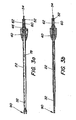
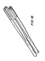
- FIGS 16-17 are perspective views of an alternate embodiment of jaw assemblies in accordance with the present invention.
- the jaw assemblies depicted in Figures 16-17 are substantially similar to jaw assembly 90, but may be used with an applier having a shaft assembly 20 with a smaller diameter, e. g. , 5 millimeters.
- the principal distinction between the jaw assemblies depicted in Figures 16-17 and jaw assembly 90 is the elimination of bridge members 104,124 in favor of making each jaw member a discrete component.
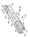
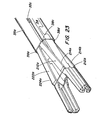
- Figures 21-24 are perspective views of the distal end of a clip applier illustrating an alternate embodiment of a jaw assembly 200.
- Figure 21 illustrates the distal end of the applier with the collar removed to better illustrate the jaw assembly 200.
- the jaw assembly 200 includes a first jaw member 210 including leg member 212a connected to the clip channel 72 at a pivot point 216a, and leg member 212b connected to the clip channel 72 at a pivot point 216b (not visible) on the opposite side of clip channel 72.
- Each leg member has a cam surface 214a, 214b.
- the distal end of the jaw assembly forms a jaw 218.
- the second jaw member 220 may be substantially identical to the first jaw member 210.
- Second jaw member 220 includes leg member 222a connected to the clip channel 72 at a pivot point 226a, and leg member 222b connected to clip channel 72 at a pivot point 226b (not visible) on the opposite side of clip channel 72.
- Each leg member has a cam surface 224a, 224b.
- the distal end of the jaw assembly forms a jaw 228.
- Tabs 240, 242 extend from the surface of clip cartridge 72 and function as cams to bias the proximal end of jaw legs 212,222, respectively, outwardly. This tends to bias the jaw assembly toward a closed configuration.
- jaws 218,228 may be opened and closed by pivoting the jaw members about the respective pivot points.
- Figures 22-24 are sequence views of the distal end of the applier that illustrate closing the jaw assembly.
- Figure 22 depicts the jaw assembly in the clip feed position, in which the jaws 218,228 preferably are substantially aligned with surfaces of the clip channel 72 to facilitate the smooth transfer of a clip from the clip channel 72 into the jaw assembly.
- tabs 240,242 of clip channel 72 bias the proximal end of jaw legs 212,222 outwardly.
- Collar 34 limits the outward motion of the proximal end of jaw legs 212,222, which preferably are dimensioned such that the jaw assembly is at rest as depicted in Figure 22 .
- Figure 23 depicts the jaw assembly in an open configuration. As discussed above, driving a clip in the jaw assembly forward will open the jaw assembly (the clip is omitted in Figure 23 for clarity of illustration). The opening of the jaw assembly is limited by contact between the cam surfaces of the jaw members and the corresponding cam surfaces 38a-38d of the collar 32.
- Figure 24 depicts the jaw assembly in a closed configuration.
- cams 38a-38d impinge on the cam surfaces 214a, 214b, 224a, 224b, which closes the jaw assembly.
- Collar 34 includes slots 35a-35d that allow the rear portions of jaw legs 212,222 to extend outwardly so that the jaws can close.
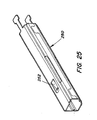
- Figure 25 depicts an alternate embodiment of a collar 250 adapted for use with the jaw assembly 200 depicted in Figures 21-24 .
- Collar 250 is substantially similar to the collar depicted in Figures 21-24 , and includes a tab 252 that extends into the chamber defined by the collar 250 to prevent the jaws 210,220 from unintended closing, e. g. , due to pressure inside the body cavity.
- tab 252 fits between leg members 212a, 222a to prevent jaw assembly 200 from closing.
- the tab 252 moves distally, allowing the jaw assembly 200 to close.
- FIG. 1 An exemplary embodiment of the invention has been described in which the clip cartridge is retained substantially in a fixed spatial relationship with the fixed grip 142, and the actuation assembly moves the feeder bar 80 to advance clips in the clip channel 72 and outer shaft assembly 20 to close the jaw assembly 90.
- the shaft assembly 20 could remain fixed, and the actuation assembly could move the clip channel 72 relative to the fixed shaft to close the jaw assembly 90.
- the clip channel 72 could be biased in a distal direction and the pivot point 146 of trigger 144 could be repositioned such that actuating the trigger 144 retracts clip channel 72 in a proximal direction.
- feeder bar 80 could be fixed, such that retracting clip channel 72 in a proximal direction advances clips in the clip channel.
Abstract
Description
- This invention generally relates to an applier for surgical clips. More particularly, this invention relates to a ligating clip applier capable of sequentially delivering a number of clips stored in a clip channel.
- Laparoscopic, endoscopic, and other minimally invasive surgical techniques enable surgeons to perform fairly complicated procedures through relatively small entry points in the body. The term "laparoscopic" refers to surgical procedures performed on the interior of the abdomen, while the term "endoscopic" refers more generally to procedures performed in any portion of the body. Endoscopic surgery involves the use of an endoscope, which is an instrument permitting the visual inspection and magnification of a body cavity. The endoscope is inserted into a body cavity through a cannula extending through a hole in the soft tissue protecting the body cavity. The hole is made with a trocar, which includes a cutting instrument slidably and removably disposed within a trocar cannula. After forming the hole, the cutting instrument can be withdrawn from the trocar cannula. A surgeon can then perform diagnostic and/or therapeutic procedures at the surgical site with the aid of specialized medical instruments adapted to fit through the trocar cannula and additional trocar cannulas providing openings into the desired body cavity.
- Some known advantages of minimally invasive surgical techniques include reduced trauma to the patient, reduced likelihood of infection at the surgical site, and lower overall medical costs. Accordingly, minimally invasive surgical techniques are being applied to an increasingly wider array of medical procedures.
- Many surgical procedures require body vessels to be ligated during the surgical process. For example, many surgical procedures require cutting blood vessels (e. g. , veins or arteries), and these blood vessels may require ligation to reduce bleeding. In some instances a surgeon may wish to ligate the vessel temporarily to reduce blood flow to the surgical site during the surgical procedure.
- In other instances a surgeon may wish to permanently ligate a vessel.
- Vessel ligation may be performed by closing the vessel with a ligating clip, or by suturing the vessel with surgical thread. Performing vessel ligation using surgical thread requires complex manipulations of the needle and suture material to form the knots required to secure the vessel. Such complex manipulations are timeconsuming and difficult to perform, particularly in endoscopic surgical procedures, which are characterized by limited space and visibility. By contrast, ligating clips are relatively easy and quick to apply. Accordingly, the use of ligating clips in endoscopic surgical procedures has grown dramatically.
- Ligating clips may be classified according to their geometric configuration as either symmetric clips or asymmetric clips, and according to the material from which they are manufactured. Symmetric clips are generally"U"or"V"shaped metallic clips that are substantially symmetrical about a central, longitudinal axis extending between the legs of the clip. By contrast, asymmetric clips lack an axis of symmetry. For example,
U. S. Patent No. 4,834, 096 to Oh et al. describes a polymeric, asymmetric surgical clip in which a first leg member includes a lip that mates with the second leg member to lock the clip in place. Asymmetric clips have certain advantages over symmetric clips. For example, because asymmetric clips are formed from polymeric materials, the mouths of asymmetric clips can be opened wider than the mouths of symmetric clips. This allows a surgeon to position the clip about the desired vessel with greater accuracy. In addition, a clip of the type described inU. S. Patent No. 4,834, 096 can be repositioned before locking the clip on the vessel, a process referred to as"approximating"the clip, or to be removed from the vessel. - Ligating clips are applied using mechanical devices commonly referred to as surgical clip appliers, ligating clip appliers, or hemostatic clip appliers. Surgical clip appliers adapted for endoscopic surgical techniques include a shaft adapted to be inserted through an endoscopic cannula to access a surgical site in a body cavity and a jaw assembly disposed at the distal end of the shaft for retaining a surgical clip. In use, the clip is positioned over the desired vessel and the jaw is actuated, typically using a mechanism disposed in the handle of the device, to close the clip about the vessel.
- Multiple clip applier systems have been developed that enable surgeons to deliver multiple symmetric surgical clips to an endoscopic surgical site. In general, these systems provide a surgical clip channel within the shaft of the device and a mechanism for delivering the surgical clips through the shaft to the jaw assembly.
- For example,
U. S. Patent Nos. 5,100, 420 and5,645, 551 to Green et al. describe a device for delivering and applying multiple surgical clips to an endoscopic surgical site. Similarly,U. S. Patent No. Re 35,525 to Stefanchik et al. aims to provide an endoscopic multiple ligating clip applier with a venting system. U. S. Patent No. -
5,700, 271 to Whitfield et al. , European Published Patent Application No.0 409 569 Al, and European Patent No.0 596 429 B 1 propose other clip applier designs. - As endoscopic techniques have been developed, certain inadequacies in the available surgical equipment have become apparent. For example, the jaws of the applier, which are typically used to close a clip around a vessel, may exert unequal pressure on the clip, resulting in a"scissoring"effect and damage to the vessel. In other instances, the clip may not be properly oriented when it is placed within the jaws or may slip out of alignment during application. This may result in the loss or misapplication of the clip. In still other instances, the applier may jam or may simply fail to deploy a clip.
- Further, existing multiple clip applier systems have been designed for symmetric clips and are not well suited to satisfy design issues unique to asymmetric clips. For example, symmetric clips can be retained in clip jaws by holding opposing surfaces of the clip's legs in opposing channels. By contrast, asymmetric clips cannot easily be retained in opposing channels because the clip's legs deform when the clip is closed. In addition, when symmetric clips are closed on a vessel, the opposing legs of the clip apply substantially even pressure to the opposing sides of the vessel. By contrast, the opposing legs of an asymmetric clip may apply varying pressure to opposing sides of a vessel when the asymmetric clip is closed.
- Further, locking asymmetric clips of the type described in
U. S. Patent No. 4,834, 096 function best when force is applied at or near the distal ends of the clip legs. Still further, asymmetric clips of the type described inU. S. Patent No. 4,834, 096 may need to be placed under compression to be retained in the clip channel. Thus, conventional clip advancing mechanisms designed for symmetric clips may not reliably advance asymmetric clips. In addition, conventional clip advancing mechanisms designed for symmetric clips may not provide the ability to approximate a clip. - In sum, conventional clip appliers designed for symmetric, metal clips suffer from certain deficiencies and are not adapted to deliver asymmetric, polymer based clips. Accordingly, there is a need to provide an endoscopic clip applier that can reliably deliver a sequence of clips and in a manner which minimizes the risk of damage to the vessel. Further, there is a need for an endoscopic clip applier adapted to deliver asymmetric, polymer ligating clips.
- The present invention addresses these and other needs by providing an endoscopic clip applier adapted to retain a plurality of asymmetric ligating clips in a clip channel contained within a shaft assembly, and including a jaw assembly for applying an asymmetric clip. In a preferred embodiment, the jaw assembly is connected to the distal end of the clip channel, and a handle assembly is connected to a proximal end of the clip channel. A feeder bar mounted adjacent the clip channel is moveable between a proximal position and a distal position to advance clips in the clip applier and to feed a clip from the clip channel to the jaw assembly.
- Additionally, the shaft assembly is moveable between a proximal position and a distal position, and includes cam surfaces for closing the jaw assembly when the shaft assembly is moved in a distal direction. A trigger on the handle assembly actuates the feeder bar to advance clips in the clip channel and advances the shaft assembly to close the jaw assembly. Advantageously, the shaft assembly may be rotated about its longitudinal axis.
- In one aspect the invention provides an endoscopic surgical applier having a jaw assembly adapted to establish four separate points of contact with a ligating clip to stabilize the clip in the jaw assembly. Accordingly, the invention provides an endoscopic surgical clip applier that comprises a shaft assembly having a distal end adapted for insertion through a cannula into a body cavity and a clip channel disposed within the shaft assembly for retaining a plurality of clips. A jaw assembly extends from the distal end of the shaft assembly and includes a first jaw member having a first jaw arm for engaging a first portion of a ligating clip and an opposing second jaw arm for engaging a second portion of a ligating clip, the first and second jaw arms each comprising a cam surface, and a second jaw member having a third jaw arm for engaging a third portion of a ligating clip and an opposing fourth jaw arm for engaging a fourth portion of a ligating clip, the third and fourth jaw arms each comprising a cam surface. An actuation assembly advances a clip from the clip channel to the jaw assembly.
- In another aspect the invention provides an endoscopic clip applier in which cam surfaces on the exterior shaft assembly cooperate with corresponding cam surfaces on the jaw assembly to close the jaw assembly. Accordingly, the invention provides an endoscopic surgical clip applier that comprises an exterior shaft assembly having a proximal end and a distal end adapted for insertion through a cannula into a body cavity and having a plurality of cam surfaces formed at the distal end. A jaw assembly extends from the distal end of the shaft assembly and includes a first jaw member having a first jaw arm for engaging a first portion of a ligating clip and an opposing second jaw arm for engaging a second portion of a ligating clip. The first and second jaw arms each comprise a cam surface, as do the third and fourth jaw arms. Contained within the exterior shaft assembly are a clip channel adapted to hold a plurality of clips, and a feeder bar for feeding clips from the clip channel to the jaw assembly. An actuation assembly for closing the jaw assembly induces relative motion between the exterior shaft assembly and the jaw assembly so that contact between the cam surfaces closes the jaw assembly.
- In yet another aspect the invention provides an endoscopic surgical clip applier that allows a user to approximate a surgical clip before locking the clip on a vessel. Accordingly, an endoscopic surgical clip applier comprises an exterior shaft assembly having a proximal end and a distal end adapted for insertion through a cannula into a body cavity. A clip channel is disposed within the exterior shaft assembly for holding a plurality of clips, and a jaw assembly is connected to the distal end of the clip channel. An actuation assembly includes a trigger for implementing an actuation stroke having a first portion for advancing a clip from the clip channel into the jaw assembly and a second portion for closing the jaw assembly. A ratchet assembly is connected to the trigger, wherein the ratchet assembly precludes reverse motion of the trigger during the first portion of the actuation stroke, but allows reverse motion of the trigger during the second portion of the actuation stroke.
- Objects and advantages of the invention will be understood by reading the following detailed description in conjunction with the drawings in which:
-
Figure 1 is a perspective view of a clip applier constructed in accordance with the present invention; -
Figure 2a is a perspective view of a shaft assembly of a clip applier in accordance with the present invention; -
Figure 2b is an assembly view of the shaft assembly depicted inFig. 2a ; -
Figure 2c is an enlarged assembly view of portions of the shaft assembly depicted inFigure 2b ; -
Figure 3a is a cross-sectional view, taken in a plane parallel to the jaw members, of a shaft assembly of a clip applier in accordance with the present invention; -
Figure 3b is a cross-sectional view, taken in a plane perpendicular to the jaw members, of a shaft assembly of a clip applier in accordance with the present invention; -
Figure 4 is an assembly view of a handle assembly in accordance with the present invention; -
Figure 5 is a perspective view of the interior of a handle assembly in accordance with the present invention; -
Figure 6 is a partial cut-away view of a handle assembly in accordance with the present invention; -
Figure 7 is a partial cut-away view of a handle assembly in accordance with the present invention; -
Figures 8-10 are partial cut-away views of a clip channel during a clip advancing process; -
Figure 11 is a partial cut-away view of a handle assembly in accordance with an embodiment of the present invention; -
Figures 12-14 are perspective views of the jaw assembly during the process of closing a clip; -
Figures 15a-15c are a perspective views of alternate embodiments of yokes in accordance with the present invention; -
Figures 16-17 are perspective views of jaw assemblies in accordance with the present invention; -
Figure 18 is a perspective view of a collar in accordance with an embodiment of the present invention; -
Figure 19 is a perspective view of the distal end of a feeder bar in accordance with an embodiment of the present invention; -
Figure 20 is a perspective view of the distal end of a clip channel in accordance with an embodiment of the present invention; and -
Figures 21-24 are perspective views of an alternate embodiment of a jaw assembly in accordance with the present invention -
Figure 25 is a perspective view of an alternate embodiment of a collar in accordance with the present invention. - Referring to
Figure 1 , an exemplary embodiment of anendoscopic clip applier 10 in accordance with the present invention includes ashaft assembly 20 having ajaw assembly 90 disposed at a distal end and ahandle assembly 140 disposed at a proximal end. Thehandle assembly 140 includes astationary grip 142 and amoveable trigger 144 for actuating theclip applier 10. In use, thejaw assembly 90 may be positioned inside a body cavity, for example by passing theshaft assembly 20 through an endoscopic cannula, to apply a ligating clip to a body vessel. -
Figure 2a is a perspective view andFigures 2b and2c are exploded assembly views of an exemplary embodiment ofshaft assembly 20 andjaw assembly 90. -
Shaft assembly 20 includes a cylindricalouter shaft member 22, which may be formed from two semi-cylindricalouter shaft members outer shaft member 22 may be formed from a single tubular member, or may be of a rectangular or polygonal cross-section.Outer shaft member 22 includes a proximal flange 24, indicated byproximal flanges shaft members pin slots outer shaft members channels shaft member 22 is assembled.Outer shaft 22 may be formed from a suitably rigid material, e. g. , a suitable polymer or metal. - At the distal end,
shaft 22 may taper from a cylindrical cross-section to a substantially rectangular cross-section. A collar 32 (Figure 18 ) haskeys key slots 30a, 30b for connecting thecollar 32 toouter shaft member 22.Collar 32 preferably is substantially rectangular in cross-section and includes fourcam surfaces keys 36a, 36b at its distal end.Collar 32 may be formed from suitably rigid material, e. g. , a suitable polymer or metal. - A
clip feed assembly 70 is disposed within theshaft 22 andcollar 32.Clip feed assembly 70 includes achannel 72 forhousing clips 78 andfeeder bar 80 that is moveable along the longitudinal axis ofshaft 22 for moving clips disposed inchannel 72 toward the distal end of theapplier 10.Channel 72 includes apin hole 74 near the proximal end and a plurality oftabs 76 near its base.Channel 72 may be formed from suitably rigid material, e. g. , a suitable polymer or metal. -
Feeder bar 80 includes apin slot 82 and a plurality oftabs 84 which act as clip advancing elements to move theclips 78 inchannel 72 toward the distal end of theapplier 10. Eachtab 84 may be formed by stamping or cutting a portion of the body of thefeeder bar 80. Thetab 84 remains attached to the body of thefeeder bar 80 at the proximal end of thetab 84. Eachtab 84 may be bent or otherwise directed toward the interior of theclip channel 72. Thetabs 84 may have a substantially uniform length, which may be determined by the length and geometry of the endoscopic clip, and by the rigidity of the material from which thefeeder bar 80 is manufactured. Thetabs 84 may be located along either the top or bottom (or both) edges of the side of the clip channel.Feeder bar 82 may be formed from suitably rigid material, e. g. , a suitable polymer or metal. -
Shaft assembly 20 further includes ayoke 50, a portion of which is disposed within thehandle assembly 140, for translating longitudinal motion tofeeder bar 80 andouter shaft 22.Feeder bar 80 includes atab 86 that rests adjacent an interiordistal edge 57 of yoke 50 (Fig. 15c ). A portion of theyoke body 56 extends along a portion of the length offeeder bar 80 and has aslot 58 that aligns withpin slot 82 whenyoke 50 is connected tofeeder bar 80.Yoke 50 further includes aflange 52 andpin 54 on its proximal end.Yoke 50 may be formed from suitably rigid material, e. g. , a suitable polymer or metal. Afeeder spring 60 is positioned within thebody 56 ofyoke 50 for biasing the feeder bar toward the distal end ofyoke 50. - A
tube spring 62 is positioned betweenflange 52 and aflange 42 onknob 40 for biasing theyoke 50 toward the proximal end of the shaft assembly. Aknob spring 64 is disposed withinknob 40 and biases theouter shaft 22 in a proximal direction. - A
jaw assembly 90 is connected to the distal end ofclip channel 72.Jaw assembly 90 includes afirst jaw member 92 having a first leg 94 and asecond leg 99 connected by a bridge member 104. First leg 94 includes afirst cam surface 96 and afirst jaw arm 98, andsecond leg 99 includes asecond cam surface 100 and asecond jaw arm 102. Bridge member 104 includes a slot 106 for receiving a conventional fastener (e. g. , rivets, pins, screws, tabs, etc. ) to connectfirst jaw member 92 tochannel 72.Jaw assembly 90 further includes asecond jaw member 110 having athird leg 112 and afourth leg 118 connected by abridge member 124. -
Third leg 112 includes athird cam surface 114 and athird jaw arm 116, andfourth leg 118 includes afourth cam surface 120 and afourth jaw arm 122.Bridge member 124 includes aslot 126 for receiving a conventional fastener (e. g. , rivets, pins, screws, tabs, etc. ) to connectsecond jaw member 110 tochannel 72.Jaw assembly 90 further includes afirst guide 130 adapted to clip overfirst jaw arm 98 andthird jaw arm 116 and asecond guide 132 adapted to clip oversecond jaw arm 102 andfourth jaw arm 122.Jaw assembly 90 may be formed from suitably rigid material, e. g. , a suitable polymer or metal. -
Figures 3a and 3b are cross-sectional views of an assembled shaft assembly of a clip applier in accordance with the present invention. When assembled, thejaw assembly 90,clip feed assembly 70, andyoke 50 are connected as described herein and extend throughouter shaft 22.Knob 40 is mounted to the exterior ofshaft 22 and secured using conventional fasteners (e. g. , pins, rivets, screws, adhesives, etc.). - A
pin 46 extending throughknob 40 and throughpin hole 74 inchannel 72 retainschannel 72 in a fixed position with respect toknob 40. For clarity,Figure 3a illustrates aclip channel 72 having asingle clip 78, but it will be appreciated that theclip channel 72 may be filled with a plurality (e. g. , 2-100) clips. The diameter ofshaft 22 is determined by the diameter of the cannula through which theshaft 22 must pass to enter a body cavity. Many existing surgical procedures use a cannula having an inner diameter measuring approximately 10 millimeters. Accordingly, in one embodiment of the invention, theshaft 22 has an outer diameter slightly less than 10 millimeters. In an alternate embodiment, theshaft 22 may be dimensioned to fit within a cannula having a diameter of 5 millimeters. It will be appreciated, however, that the diameter of theshaft 22 is not critical to the invention; any other diameter may be used as desired. - Referring to
Figure 4 andFigure 5 , ahandle assembly 140 includes a fixedgrip 142, which may be manufactured in two substantiallysymmetrical parts trigger 144 is pivotally mounted to fixedgrip 142 about apivot point 146. -
Trigger 144 includes agrooved claw 148 that impinges onflange 52 to translate the rotary motion oftrigger 144 aboutpivot point 146 to linear motion ofyoke 50 relative to fixedgrip 142 in the distal direction.Grooved claw 148 also receives thepin 54 ofyoke 50. This arrangement enables a user to forceyoke 50 in a proximal direction if necessary, which provides a safety feature.Fixed grip 142 further includes arim 150 that secures theflange 42 ofknob 40, such thatknob 40 andchannel 72 are maintained in a substantially fixed longitudinal position relative to fixedgrip 142. Theentire shaft assembly 20 is rotatable about its longitudinal axis, andknob 40 includes fins 44 that facilitate rotating theshaft assembly 20. - A
ratchet key 152 extends from the rear oftrigger 144 and contacts ratchetguide 154 to inhibit backward motion oftrigger 144 through a portion of the actuation stroke. Preferably, the toothed surface portion ofratchet guide 154 corresponds to the range ofmotion trigger claw 148 covers while thefeeder bar 80 is moved forward to advance the clips in clip channel 72 (i. e. , the feed stroke). The smooth surface portion ofratchet guide 154 preferably corresponds to the range ofmotion trigger claw 148 covers during the portion of the actuation stroke that closes thejaw assembly 90. When the device is actuated, the transition of theratchet key 152 from the ratchet surface portion to the smooth surface portion provides the user with tactile feedback indicating that the feed stroke is complete and a clip has been fed to thejaw assembly 90. In addition, the smooth surface portion permits a user to approximate a clip. - Basic structural elements of one embodiment of a
clip applier 10 have been described with reference toFigures 1-5 . The interaction of the structural elements and the operation of the device will be explained with reference toFigures 6-24 . -
Figure 6 is a partial cut-away, side view of the proximal end ofclip applier 10 with the device in an unactuated state. Referring toFigure 6 ,yoke 50 is biased to its most proximal position bytube spring 62. In the unactuated state, thejaws 90 are partially open, as depicted inFigure 1 .Trigger 144 andyoke 50, in combination, may be considered an actuation assembly for actuating theclip feed assembly 70 and thejaw assembly 90. -
Figure 7 is a side cut-away view of the proximal end ofclip applier 10 with the device in a partially actuated state. Forward motion ofyoke 50places tube spring 62 under compression. In one embodiment, the spring coefficient offeeder spring 60 is higher than the amount of force required to advance thefeeder bar 80. - Therefore, the
feeder spring 60 effectively functions as a solid piece of material during the feed stroke. - According to one aspect of the invention, the first portion of the stroke of
trigger 144 is a feed stroke that advancesyoke 50 andfeeder bar 80 relative to the fixedchannel 72. When thefeeder bar 80 is advanced, thetabs 84 engage theclips 78 inchannel 72 and advance theclips 78 toward the distal end ofapplier 10. The mostdistal clip 78 is fed into thejaw assembly 90.Figures 8-10 are partial cutaway views of the clip feeder assembly illustrating the advance of a position to the most distal during the feed stroke. For clarity of illustration, the distal end offeed bar 80 has been cut-away inFigures 8-10 .Figure 8 illustrates the beginning of a feed stroke, in which thetab 84 offeeder bar 80 is brought into contact with a boss 79a ofclip 78 disposed inchannel 72. InFigure 9 , further actuation oftrigger 144 moves thefeeder bar 80 in a distal direction, which advancesclip 78 toward the distal end ofchannel 72. InFigure 10 thefeeder bar 80 has advancedclip 78 to the most distal position inchannel 72. For clarity,Figures 8-10 illustrate the advance of asingle clip 78 toward the distal end ofapplier 10, but it will be appreciated that the clip channel may include a plurality (e. g. , 2-100) of clips, each of which is advanced by atab 84 offeeder bar 80. In one embodiment,channel 72 holds twenty (20) clips. - During the feed stroke, the most distal clip is fed from the
channel 72 to thejaw assembly 90. According to one aspect, thefeeder bar 80 and theclip channel 72 include structure particularly adapted to feed the mostdistal clip 78 into thejaw assembly 90. In an exemplary embodiment, the distal end ofchannel 72 andfeeder bar 80 include structural features adapted to feed the most distal clip into thejaw assembly 90. Referring toFigure 19 , the distal end offeeder bar 80 includes afeeder tab 88 adapted to contact the central, rear portion of the most distal clip to push the clip into thejaw assembly 90. In addition,feeder bar 80 includes afoot member 89 that rotates the rear of the most distal clip during the return stroke so the rear portion of the clip is positioned to contactfeeder tab 88. Preferably, the interior surfaces of the jaw assembly that receive the clips are of substantially the same width as thechannel 72 to provide a smooth transition between thechannel 72 and thejaw assembly 90. - Referring to
Figure 20 , the distal end ofchannel 72 includes atab 71 that catches the boss on the mostdistal clip 78 when thefoot member 89 offeeder bar 80 rotates the clip during the return stroke, thereby limiting the rotation of the clip. In addition, opposingribs 73a, 73b facilitate centering the rear of the most distal clip (in the lateral direction) so the rear portion of the clip is positioned to contactfeeder tab 88. The distal end ofchannel 72 further includes upper andlower tabs clip 78 into thejaw assembly 90. In addition, opposinglateral tabs clip 78 into the jaw assembly and to inhibit lateral motion of the rear portion of the clip when the clip is in thejaw assembly 90.Figure 20 also provides a view oftabs 76 that inhibit clips 78 from sliding in a proximal direction during the return stroke offeeder bar 80, and of tabs 79a-79d for securing a jaw member to clipchannel 72. - According to another aspect, the
applier 10 is configured such that further actuation of the trigger functions to open aclip 78 disposed in thejaw assembly 90. - The
clips 78 are fed throughchannel 72 in a compressed configuration, which reduces the required diameter of theshaft assembly 22. The mostdistal clip 78 is fed into thejaw assembly 90 in the same compressed configuration. As illustrated inFigure 12 , hooks 98,102, 116,122 limit the forward motion ofclip 78 injaw assembly 90. Therefore, when further pressure is applied to the rear ofclip 78 via thefeeder tab 88 offeeder bar 80, the force is translated through the legs ofclip 78, which causes the jaw assembly 90 (and theclip 78 contained therein) to open wider. - The width to which the
jaw assembly 90 may be limited by the cam surfaces 38a- 38d ofcollar 34. - Following completion of the feed stroke, further actuation of the
trigger 144 actuates thejaw assembly 90.Figure 11 is a side cut-away view of the proximal end ofclip applier 10 with the device in a fully actuated state.Pin 46 is always in clearance with the channel 26 inshaft member 22. Arib 149 inhandle body 142 limits the forward motion of theclaw 148 portion oftrigger 144, and hence limits the forward motion ofyoke 50. -
Figures 12-14 are perspective views of distal end ofapplier 10 illustrating thejaw assembly 90 while it is being closed. Referring first toFigure 12 , following completion of the feed portion of the stroke, aclip 78 is positioned in thejaw assembly 90, which is in an open configuration. According to another aspect of the invention, the second portion of the stroke oftrigger 144 closes thejaw assembly 90. - More particularly, referring to
Figures 13-14 , the second portion of the stroke movesouter shaft 22 in a distal direction relative to the fixedgrip 142,knob 40, andclip channel 72. As theouter shaft 22 andcollar 34 are moved in a distal direction, cam surfaces 38a-38d ofcollar 34 impinge on cam surfaces 96,100, 114,120, closing thejaw assembly 90. The use of four separate cams reduces the likelihood of scissoring as thejaw assembly 90 is closed. - While the
jaw assembly 90 is closing, thefeeder tab 88 offeed bar 80 remains in contact with the rear ofclip 78. Closing the jaw assembly tends to drive the rear ofclip 78 in a proximal direction, which increases the pressure between thefeeder tab 88 and theclip 78 injaw assembly 90, thereby enhancing the stability of theclip 78 in the jaw assembly. This enhanced clip stability is particularly advantageous when a surgeon is pushing a clip onto a vessel. - Additional features of
applier 10 will be explained with reference toFigures 12-15 . Each jaw arm 98,102, 116,122 terminates in a hook. The hook offirst jaw arm 98 andthird jaw arm 116 cooperate to retain boss 79a ofclip 78 injaw assembly 90. Similarly, the hook ofsecond jaw arm 102 andfourth jaw arm 122 cooperate to retainboss 79b ofclip 78 injaw assembly 90. This configuration ofjaw assembly 90 provides four distinct points of contact betweenjaw assembly 90 andclip 78, which reduces the likelihood of thejaw assembly 90 scissoring while it is closing. In addition, this configuration permits the force applied by thejaw assembly 90 to be applied to the distal end of theclip 78, which facilitates locking the clip. The rear (i. e. , proximal) portion ofclip 78 is retained betweentabs clip channel 72, which limits the range of lateral motion available to clip 78. In addition, thefeed tab 88 offeed bar 80 prevents the rear (i. e. , proximal) portion ofclip 78 from being pushed back into theclip channel 72 when theclip 78 is being applied. Accordingly, theclip 78 is maintained stable in three dimensions while retained in thejaw assembly 90. - According to another feature of the invention, only a portion of the
ratchet guide 154 includes ratchet teeth. Preferably the length ofratchet guide 154 having teeth corresponds to the feed portion of the actuation stroke oftrigger 144. - Reversing the direction of
feeder bar 80 during the feed stroke may cause the clip to become unstable, or even to fall out of thejaw assembly 90. The teeth onratchet guide 154 inhibitsfeeder bar 80 from being moved in a proximal direction during the feed stroke. A second portion ofratchet guide 154, which preferably corresponds to the portion of the stroke during which the jaw is closed, permits theyoke 50 and theouter shaft 22 to move freely in the distal direction and the proximal direction. This allows a user to"approximate"a clip during the closing process, i. e., to partially close a clip then to re-open the jaws to reposition a clip, if necessary. - In another aspect, the
distal collar keys 36a, 36b provide a stop to prevent the jaws from unintended closings during use, e. g. , under compression as may be incurred during use in the body. Referring toFigure 13 it can be seen that the distal portion ofcollar keys 36a, 36b include an inwardly-turned segment positioned to block thelegs leg members Figure 14 , when theshaft 22 is advanced, thekeys 36a, 36b advance past the taper in the jaws, allowing the jaws to close. Additionally, thecollar keys 36a, 36b function as cams to facilitate re-opening the jaws after the device is actuated andouter shaft 22 retracts. -
Figure 14 illustrates thejaw assembly 90 in a substantially closed configuration. Further actuation of thejaw assembly 90 will lock theclip 78. The distal motion ofouter shaft 22 compresses theknob spring 64 between the flange 24 and the interior distal edge ofknob 40, which provides the bias force to returntrigger 144 andouter shaft 22 to its unactuated state. After thejaw assembly 90 is closed, the user may release the trigger, and the bias force provided byknob spring 64 urgesshaft 22 andfeeder bar 80 in a proximal direction. This"resets"theapplier 10 back to an unactuated state so that another clip may be fed to the jaw assembly. - During the reset sequence, the
tabs 76 onclip channel 72 inhibit theclips 78 inchannel 72 from moving in the proximal direction. Thetabs 84 on thefeeder bar 80 move across theclips 78 inchannel 72 and snap into position behind the bosses of the clips. As thefeeder bar 80 moves proximally, thefoot member 89 of thefeeder bar 80 contacts theboss 79b of the mostdistal clip 78 in theclip channel 72, causing theclip 78 to rotate. Rotation of the mostdistal clip 78 stops when the boss 79a contacts the mostdistal tab 84 offeeder bar 80, which preferably positions the rear ofclip 78 substantially in the center of thechannel 72. As thefeeder bar 80 continues to move proximally, thefeed tab 88 is positioned adjacent the rear of the mostdistal clip 78, ready for the next actuation cycle. -
Figures 15a-15b illustrate alternate embodiments of a yoke in accordance with the present invention.Fig. 15a is a perspective view of an alternate embodiment of a two-part yoke 180 prior to assembly, andFigure 15b is a perspective view ofyoke 180 after assembly.Yoke 180 includes afirst body portion 182 and asecond body portion 184 connected by apin 186. Thefeeder spring 60 may be disposed entirely within thefirst body portion 182 ofyoke 180. In other respects,yoke 180 is substantially similar toyoke 50. Advantages of a two-piece yoke as depicted inFigures 15a-15b include better retention offeeder spring 60 within the body of the yoke and ease of assembly.Figure 15c is a perspective view ofyoke 50 depicted inFigure 2 , but from the opposite side to illustrate the interiordistal edge 57 that receives thetab 86 offeeder bar 80. -
Figures 16-17 are perspective views of an alternate embodiment of jaw assemblies in accordance with the present invention. The jaw assemblies depicted inFigures 16-17 are substantially similar tojaw assembly 90, but may be used with an applier having ashaft assembly 20 with a smaller diameter, e. g. , 5 millimeters. The principal distinction between the jaw assemblies depicted inFigures 16-17 andjaw assembly 90 is the elimination of bridge members 104,124 in favor of making each jaw member a discrete component. -
Figures 21-24 are perspective views of the distal end of a clip applier illustrating an alternate embodiment of ajaw assembly 200.Figure 21 illustrates the distal end of the applier with the collar removed to better illustrate thejaw assembly 200. Thejaw assembly 200 includes afirst jaw member 210 includingleg member 212a connected to theclip channel 72 at apivot point 216a, andleg member 212b connected to theclip channel 72 at a pivot point 216b (not visible) on the opposite side ofclip channel 72. Each leg member has acam surface jaw 218. Thesecond jaw member 220 may be substantially identical to thefirst jaw member 210.Second jaw member 220 includesleg member 222a connected to theclip channel 72 at apivot point 226a, and leg member 222b connected to clipchannel 72 at a pivot point 226b (not visible) on the opposite side ofclip channel 72. Each leg member has acam surface 224a, 224b. The distal end of the jaw assembly forms ajaw 228.Tabs clip cartridge 72 and function as cams to bias the proximal end of jaw legs 212,222, respectively, outwardly. This tends to bias the jaw assembly toward a closed configuration. - It will be appreciated that jaws 218,228 may be opened and closed by pivoting the jaw members about the respective pivot points.
Figures 22-24 are sequence views of the distal end of the applier that illustrate closing the jaw assembly.Figure 22 depicts the jaw assembly in the clip feed position, in which the jaws 218,228 preferably are substantially aligned with surfaces of theclip channel 72 to facilitate the smooth transfer of a clip from theclip channel 72 into the jaw assembly. As described above, tabs 240,242 ofclip channel 72 bias the proximal end of jaw legs 212,222 outwardly.Collar 34 limits the outward motion of the proximal end of jaw legs 212,222, which preferably are dimensioned such that the jaw assembly is at rest as depicted inFigure 22 . -
Figure 23 depicts the jaw assembly in an open configuration. As discussed above, driving a clip in the jaw assembly forward will open the jaw assembly (the clip is omitted inFigure 23 for clarity of illustration). The opening of the jaw assembly is limited by contact between the cam surfaces of the jaw members and the corresponding cam surfaces 38a-38d of thecollar 32. -
Figure 24 depicts the jaw assembly in a closed configuration. As described above in connection withFigures 12-14 , whencollar 34 is advanced,cams 38a-38d impinge on thecam surfaces Collar 34 includesslots 35a-35d that allow the rear portions of jaw legs 212,222 to extend outwardly so that the jaws can close. -
Figure 25 depicts an alternate embodiment of acollar 250 adapted for use with thejaw assembly 200 depicted inFigures 21-24 .Collar 250 is substantially similar to the collar depicted inFigures 21-24 , and includes atab 252 that extends into the chamber defined by thecollar 250 to prevent the jaws 210,220 from unintended closing, e. g. , due to pressure inside the body cavity. When the jaw assembly is in the unactuated position or the partially-actuated position,tab 252 fits betweenleg members jaw assembly 200 from closing. By contrast, when the assembly is fully actuated, thetab 252 moves distally, allowing thejaw assembly 200 to close. - An exemplary embodiment of the invention has been described in which the clip cartridge is retained substantially in a fixed spatial relationship with the fixed
grip 142, and the actuation assembly moves thefeeder bar 80 to advance clips in theclip channel 72 andouter shaft assembly 20 to close thejaw assembly 90. One of ordinary skill in the art will recognize that theshaft assembly 20 could remain fixed, and the actuation assembly could move theclip channel 72 relative to the fixed shaft to close thejaw assembly 90. For example, theclip channel 72 could be biased in a distal direction and thepivot point 146 oftrigger 144 could be repositioned such that actuating thetrigger 144 retractsclip channel 72 in a proximal direction. Similarly,feeder bar 80 could be fixed, such that retractingclip channel 72 in a proximal direction advances clips in the clip channel. - Further embodiments are included which have been already disclosed in the parent application as filed:
- 1. Embodiment: An endoscopic surgical clip applier, comprising: a shaft assembly having a distal end adapted for insertion through a cannula into a body cavity; a clip channel disposed within the shaft assembly for retaining a plurality of clips; a jaw assembly extending from the distal end of the shaft assembly and comprising: a first jaw member having a first jaw arm for engaging a first portion of a ligating clip and an opposing second jaw arm for engaging a second portion of a ligating clip, the first and second jaw arms each comprising a cam surface, and a second jaw member having a third jaw arm for engaging a third portion of a ligating clip and an opposing fourth jaw arm for engaging a fourth portion of a ligating clip, the third and fourth jaw arms each comprising a cam surface; and an actuation assembly for advancing a clip from the clip channel to the jaw assembly and closing the jaw assembly.
- 2. Embodiment: The clip applier of embodiment 1, wherein the shaft assembly includes: an outer shaft member having a longitudinal axis extending along its length; a clip channel disposed within the shaft member and moveable relative to the outer shaft along the longitudinal axis.
- 3. Embodiment: The clip applier of
embodiment 2, wherein: the first jaw member comprises a substantially U-shaped body segment having a first leg and a second leg connected by a bridge member, wherein the first jaw arm extends from the first leg and the second jaw arm extends from the second leg; and the second jaw member comprises a substantially U-shaped body segment having a third leg and a fourth leg connected by a bridge member, wherein the third jaw arm extends from the third leg and the fourth jaw arm extends from the fourth leg. - 4. Embodiment: The clip applier of embodiment 3, wherein: the bridge member of the first jaw member is connected to a first side of the clip channel; and the bridge member of the second jaw member is connected to a second side of the clip channel, opposite the first side.
- 5. Embodiment: The clip applier of embodiment 3, wherein: the bridge member of the first jaw member is pivotally connected to a first side of the clip channel; and the bridge member of the second jaw member is pivotally connected to a second side of the clip channel, opposite the first side.
- 6. Embodiment: The clip applier of embodiment 5, wherein: the outer shaft assembly includes cam surfaces adapted to cooperate with corresponding cam surfaces on the first jaw member and the second jaw member.
- 7. Embodiment: The clip applier of embodiment 6, wherein: the actuation assembly induces relative motion between the outer shaft and the clip channel, such that the cam surfaces on the outer shaft impinge upon the cams of the first jaw member and the second jaw member to close the jaw assembly.
- 8. Embodiment: The clip applier of embodiment 7, wherein the actuation assembly moves the clip channel relative to a fixed outer shaft.
- 9. Embodiment: The clip applier of embodiment 7, wherein the actuation assembly moves the outer shaft relative to a fixed clip channel.
- 10. Embodiment: The clip applier of embodiment 1, further comprising a clip feeding assembly for feeding clips from the clip channel to the jaw assembly.
- 11. Embodiment: The clip applier of embodiment 1, further comprising: a feeder bar slideably moveable along a length of the clip channel, the feeder bar having a plurality of clip advancing elements for advancing clips toward the distal end of the clip channel.
- 12. Embodiment: The clip applier of embodiment 11, wherein the feeder bar is moveable between a proximal position, in which the clip feeding mechanism retrieves a clip from the clip channel, and a distal position, in which the feeder bar delivers a clip to the jaw assembly.
- 13. Embodiment: The clip applier of embodiment 11, wherein the feeder bar includes a foot member for rotating the most distal clip in the clip cartridge when the feeder bar moves in a proximal direction.
- 14. Embodiment: An endoscopic surgical clip applier, comprising: an exterior shaft assembly having a proximal end and a distal end adapted for insertion through a cannula into a body cavity and having a plurality of cam surfaces formed at the distal end; a jaw assembly extending from the distal end of the shaft assembly and including a first jaw member having a first jaw arm for engaging a first portion of a ligating clip and an opposing second jaw arm for engaging a second portion of a ligating clip, the first and second jaw arms each comprising a cam surface; a clip channel disposed within the exterior shaft assembly and adapted to hold a plurality of clips; a feeder bar for feeding clips from the clip channel to the jaw assembly;
and an actuation assembly for closing the jaw assembly, wherein the actuation assembly induces relative motion between the exterior shaft assembly and the jaw assembly so that contact between the cam surfaces closes the jaw assembly. - 15. Embodiment: The endoscopic surgical clip applier of embodiment 14, wherein the jaw assembly includes a second jaw member having a third jaw arm for engaging a third portion of a ligating clip and an opposing fourth jaw arm for engaging a fourth portion of a ligating clip, the third and fourth jaw arms each comprising a cam surface.
- 16. Embodiment: The clip applier of embodiment 15, wherein: the first jaw member comprises a substantially U-shaped body segment having a first leg and a second leg connected by a bridge member, wherein the first jaw arm extends from the first leg and the second jaw arm extends from the second leg. the second jaw member comprises a substantially U-shaped body segment having a third leg and a fourth leg connected by a bridge member, wherein the third jaw arm extends from the third leg and the fourth jaw arm extends from the fourth leg.
- 17. Embodiment: The clip applier of embodiment 16, wherein: the bridge member of the first jaw member is pivotally connected to a first side of the clip channel; and the bridge member of the second jaw member is pivotally connected to a second side of the clip channel, opposite the first side.
- 18. Embodiment: The clip applier of embodiment 14, further comprising: a feeder bar slideably moveable along a length of the clip channel, the feeder bar having a plurality of clip advancing elements for advancing clips toward the distal end of the clip channel; and an actuating assembly for actuating the feeder bar.
- 19. Embodiment: The clip applier of embodiment 14, wherein the actuation assembly for closing the jaw assembly includes: a handle assembly including a trigger; and a yoke connected to the trigger and the outer shaft and slideably moveable along the longitudinal axis of the shaft assembly, such that depressing the trigger moves the exterior shaft relative to the jaw assembly.
- 20. Embodiment: The clip applier of embodiment 14, wherein the actuation assembly for actuating the clip feed assembly includes: a handle assembly including a trigger; and a yoke connected to the trigger and the outer shaft and slideably moveable along the longitudinal axis of the shaft assembly, such that depressing the trigger moves the feeder bar relative to the clip channel.
- 21. Embodiment: An endoscopic surgical clip applier, comprising: an exterior shaft assembly having a proximal end and a distal end adapted for insertion through a cannula into a body cavity; a clip channel disposed within the exterior shaft assembly for holding a plurality of clips; a jaw assembly connected to the distal end of the clip channel; an actuation assembly including a trigger for implementing an actuation stroke having a first portion for advancing a clip from the clip channel into the jaw assembly and a second portion for closing the jaw assembly; a ratchet assembly connected to the trigger, wherein the ratchet assembly precludes reverse motion of the trigger during the first portion of the actuation stroke, but allows reverse motion of the trigger during the second portion of the actuation stroke.
- 22. Embodiment: An endoscopic surgical clip applier according to embodiment 21, wherein: the clip exterior shaft includes a collar having a plurality of cam surfaces formed at the distal end.
- 23. Embodiment: An endoscopic surgical clip applier according to embodiment 21, wherein: the actuation assembly induces relative motion between a feeder bar and the clip channel to advance a clip from the clip channel into the jaw assembly.
- 24. Embodiment: An endoscopic surgical clip applier according to embodiment 21, wherein: the actuation assembly induces relative motion between the exterior shaft assembly and the clip channel to close the jaw assembly.
- 25. Embodiment: An apparatus for applying polymeric latching clips in an endoscopic surgical procedure, comprising:
- (a) an elongate assembly for containing polymeric latching clips, the elongate assembly comprising a distal end, an axially movable clip feeding member, and an axially movable jaw actuating member;
- (b) a jaw assembly extending from the distal end and comprising first and second opposing jaws for compressing a clip therebetween;
- (c) an actuator assembly actuatable through a first stage and a subsequent second stage of a forward stroke, the actuator assembly coupled with the clip feeding member for moving the clip feeding member into contact with the clip to feed the clip into the jaw assembly during the first stage, and the actuator assembly communicating with the jaw actuating member for moving the jaw actuating member into contact with the jaw assembly to close the clip during the second stage, wherein the clip feeding member remains coupled with the actuator assembly for maintaining contact with the clip during the second stage; and
- (d) wherein the actuator assembly comprises a movable yoke having a proximal end and a distal end, and the clip feeding member is operatively connected with the yoke and is urged thereby toward the distal end of the actuator assembly, during the first and second stages; and wherein the actuator assembly comprises a spring contacting the clip feeding member for biasing the clip feeding member toward the distal end of the yoke.
- 26. Embodiment: An apparatus for applying polymeric latching clips in an endoscopic surgical procedure, comprising:
- (a) an elongate assembly for containing polymeric latching clips, the elongate assembly comprising a distal end, an axially movable clip feeding member, and an axially movable jaw actuating member,
- (b) a jaw assembly extending from the distal end and comprising first and second opposing jaws for compressing a clip therebetween;
- (c) an actuator assembly actuatable through a first stage and a subsequent second stage of a forward stroke, the actuator assembly coupled with the clip feeding member for moving the clip feeding member into contact with the clip to feed the clip into the jaw assembly during the first stage, and the actuator assembly communicating with the jaw actuating member for moving the jaw actuating member into contact with the jaw assembly to close the clip during the second stage, wherein the clip feeding member remains coupled with the actuator assembly for maintaining contact with the clip during the second stage; and
- (d) wherein the actuator assembly comprises a movable yoke, and the clip feeding member is operatively connected with the yoke and is urged thereby toward the distal end of the actuator assembly during the first and second stages; and wherein the jaw actuating member comprises a distal section for contacting the jaw assembly during the second stage, and an opposing proximal section, and the yoke is movable into contact with the proximal section for coupling the actuator assembly with the jaw actuating member during the second stage, and wherein the actuator assembly comprises a spring contacting the yoke for biasing the yoke toward the proximal section of the jaw actuating member.
- 27. Embodiment: An apparatus for applying polymeric latching clips in an endoscopic surgical procedure, comprising:
- (a) an elongate assembly for containing polymeric latching clips, the elongate assembly comprising a clip feeding member and a jaw actuating member;
- (b) a jaw assembly for receiving clips from the elongate assembly;
- (c) an actuator assembly comprising a ratchet surface, the actuator assembly coupled to the clip feeding member for moving the clip feeding member in a distal direction during a first stroke portion for feeding a clip into the jaw assembly, and forcing said clip to an open position once in the jaw assembly, and the actuator assembly communicating with the jaw actuating member for moving the jaw actuating member into engagement with the jaw assembly during a second stroke portion for closing the jaw assembly and allowing the jaw assembly to reopen;
- (d) a ratchet member coupled to the actuator assembly and actuatable into engagement with the ratchet surface during the first stroke portion for preventing movement of the clip feeding member in a proximal direction, and actuatable out of engagement with the ratchet surface during the second stroke portion for enabling movement of the jaw actuating member in both the distal and proximal directions; and
- (e) wherein the actuator assembly comprises a yoke which includes a spring which contacts the clip feeding member for moving the clip feeding member during the first stroke portion, and the yoke is movable into contact with the jaw actuating member for moving the jaw actuating member during the second stroke portion.
- 28. Embodiment: An apparatus for applying polymeric latching clips in an endoscopic surgical procedure, comprising:
- (a) an elongate assembly for containing polymeric latching clips and comprising a distal end;
- (b) a jaw assembly for receiving a clip from the elongate assembly, the jaw assembly comprising first, second, third and fourth jaw legs spaced apart from each other for substantially simultaneously engaging at least four portions of the clip, each leg extending from the distal end and actuatable toward at least one other opposing leg for compressing the clip; and
- (c) wherein the elongate assembly comprises first, second, third, and fourth pivot points, and the first, second, third, and fourth legs are pivotably attached to the respective first, second, third, and fourth pivot points.
- 29. Embodiment: The apparatus according to embodiment 4 wherein the elongate assembly comprises a fixed member, and the first, second, third, and fourth pivot points are disposed on the fixed member.
- 30. Embodiment: The apparatus according to embodiment 5 wherein the non-actuatable member comprises a channel for containing the clips.
- 31. Embodiment: The apparatus according to embodiment 4 wherein the first, second, third, and fourth legs comprise respective first, second, third, and fourth jaw cam surfaces, and the elongate assembly comprises a jaw actuating member axially movable into contact with the first, second, third, and fourth jaw cam surfaces for actuating the jaw assembly; and wherein the jaw actuating member comprises first, second, third, and fourth distal cam surfaces respectively engageable with the first, second, third, and fourth jaw cam surfaces in response to movement of the jaw actuating member toward the jaw assembly.
- 32. Embodiment: The apparatus according to embodiment 7 wherein the jaw actuating member comprises a shaft, and the first, second, third, and fourth distal cam surfaces are formed on the shaft and generally spaced around a cross-section of the shaft.
- 33. Embodiment: An apparatus for applying polymeric latching clips in an endoscopic surgical procedure, comprising:
- (a) an elongate assembly for containing polymeric latching clips and comprising an axially movable distal end section, the distal end section comprising a plurality of distal cam surfaces generally spaced around a cross-section of the distal end section;
- (b) a jaw assembly comprising first and second opposing jaws for compressing a clip therebetween, the jaw assembly extending from the elongate assembly;
- (c) an actuator assembly communicating with the distal end section for actuating the distal cam surfaces into contact with the jaw assembly to cam the first and second jaws toward each other; and
- (d) wherein the elongate assembly comprises a shaft generally interposed between the distal end section and the actuator assembly, and the shaft is actuatable by the actuator assembly for moving the distal end section; and wherein the elongate assembly comprises a channel for containing the clips, the channel is disposed within the shaft, and the shaft and distal end section are movable relative to the channel.
- The structure of the
clip applier 10 has been generally described in relation to a single embodiment. Alternate embodiments of some components have also been described. It will be appreciated that the alternate embodiments of the components do not substantially alter the steps involved in the operation of the clip applier. In light of this disclosure, modifications to the present invention will be apparent to one skilled in the art. The modifications are intended to fall within the scope of the claims that follow.
Claims (12)
- An apparatus for applying polymeric latching clips in an endoscopic surgical procedure, comprising:(a) an elongate assembly for containing polymeric latching clips and comprising a distal end;(b) a jaw assembly for receiving a clip from the elongate assembly, the jaw assembly comprising first, second, third and fourth jaw legs spaced apart from each other for substantially simultaneously engaging at least four portions of the clip, each leg extending from the distal end and actuatable toward at least one other opposing leg for compressing the clip; and(c) wherein the elongate assembly comprises first, second, third, and fourth pivot points, and the first, second, third, and fourth legs are pivotably attached to the respective first, second, third, and fourth pivot points.
- The apparatus according to claim 1 wherein the elongate assembly comprises a fixed member, and the first, second, third, and fourth pivot points are disposed on the fixed member.
- The apparatus according to claim 2 wherein the non-actuatable member comprises a channel for containing the clips.
- The apparatus according to claim 1 wherein the first, second, third, and fourth legs comprise respective first, second, third, and fourth jaw cam surfaces, and the elongate assembly comprises a jaw actuating member axially movable into contact with the first, second, third, and fourth jaw cam surfaces for actuating the jaw assembly; and wherein the jaw actuating member comprises first, second, third, and fourth distal cam surfaces respectively engageable with the first, second, third, and fourth jaw cam surfaces in response to movement of the jaw actuating member toward the jaw assembly.
- The apparatus according to claim 4 wherein the jaw actuating member comprises a shaft, and the first, second, third, and fourth distal cam surfaces are formed on the shaft and generally spaced around a cross-section of the shaft.
- An apparatus for applying polymeric latching clips in an endoscopic surgical procedure, comprising:(a) an elongate assembly for containing polymeric latching clips and comprising an axially movable distal end section, the distal end section comprising a plurality of distal cam surfaces generally spaced around a cross-section of the distal end section;(b) a jaw assembly comprising first and second opposing jaws for compressing a clip therebetween, the jaw assembly extending from the elongate assembly;(c) an actuator assembly communicating with the distal end section for actuating the distal cam surfaces into contact with the jaw assembly to cam the first and second jaws toward each other; and(d) wherein the elongate assembly comprises a shaft generally interposed between the distal end section and the actuator assembly, and the shaft is actuatable by the actuator assembly for moving the distal end section; and wherein the elongate assembly comprises a channel for containing the clips, the channel is disposed within the shaft, and the shaft and distal end section are movable relative to the channel.
- An apparatus for applying polymeric latching clips in an endoscopic surgical procedure, comprising:(a) an elongate assembly for containing polymeric latching clips, the elongate assembly comprising a distal end, an axially movable clip feeding member, and an axially movable jaw actuating member;(b) a jaw assembly extending from the distal end and comprising first and second opposing jaws for compressing a clip therebetween;(c) an actuator assembly actuatable through a first stage and a subsequent second stage of a forward stroke, the actuator assembly coupled with the clip feeding member for moving the clip feeding member into contact with the clip to feed the clip into the jaw assembly during the first stage, and the actuator assembly communicating with the jaw actuating member for moving the jaw actuating member into contact with the jaw assembly to close the clip during the second stage, wherein the clip feeding member remains coupled with the actuator assembly for maintaining contact with the clip during the second stage; and(d) wherein the actuator assembly comprises a movable yoke having a proximal end and a distal end, and the clip feeding member is operatively connected with the yoke and is urged thereby toward the distal end of the actuator assembly, during the first and second stages; and wherein the actuator assembly comprises a spring contacting the clip feeding member for biasing the clip feeding member toward the distal end of the yoke.
- An apparatus for applying polymeric latching clips in an endoscopic surgical procedure, comprising:(a) an elongate assembly for containing polymeric latching clips, the elongate assembly comprising a distal end, an axially movable clip feeding member, and an axially movable jaw actuating member,(b) a jaw assembly extending from the distal end and comprising first and second opposing jaws for compressing a clip therebetween;(c) an actuator assembly actuatable through a first stage and a subsequent second stage of a forward stroke, the actuator assembly coupled with the clip feeding member for moving the clip feeding member into contact with the clip to feed the clip into the jaw assembly during the first stage, and the actuator assembly communicating with the jaw actuating member for moving the jaw actuating member into contact with the jaw assembly to close the clip during the second stage, wherein the clip feeding member remains coupled with the actuator assembly for maintaining contact with the clip during the second stage; and(d) wherein the actuator assembly comprises a movable yoke, and the clip feeding member is operatively connected with the yoke and is urged thereby toward the distal end of the actuator assembly during the first and second stages; and wherein the jaw actuating member comprises a distal section for contacting the jaw assembly during the second stage, and an opposing proximal section, and the yoke is movable into contact with the proximal section for coupling the actuator assembly with the jaw actuating member during the second stage, and wherein the actuator assembly comprises a spring contacting the yoke for biasing the yoke toward the proximal section of the jaw actuating member.
- An apparatus for applying polymeric latching clips in an endoscopic surgical procedure, comprising:(a) an elongate assembly for containing polymeric latching clips, the elongate assembly comprising a clip feeding member and a jaw actuating member;(b) a jaw assembly for receiving clips from the elongate assembly;(c) an actuator assembly comprising a ratchet surface, the actuator assembly coupled to the clip feeding member for moving the clip feeding member in a distal direction during a first stroke portion for feeding a clip into the jaw assembly, and forcing said clip to an open position once in the jaw assembly, and the actuator assembly communicating with the jaw actuating member for moving the jaw actuating member into engagement with the jaw assembly during a second stroke portion for closing the jaw assembly and allowing the jaw assembly to reopen;(d) a ratchet member coupled to the actuator assembly and actuatable into engagement with the ratchet surface during the first stroke portion for preventing movement of the clip feeding member in a proximal direction, and actuatable out of engagement with the ratchet surface during the second stroke portion for enabling movement of the jaw actuating member in both the distal and proximal directions; and(e) wherein the actuator assembly comprises a yoke which includes a spring which contacts the clip feeding member for moving the clip feeding member during the first stroke portion, and the yoke is movable into contact with the jaw actuating member for moving the jaw actuating member during the second stroke portion.
- An endoscopic surgical clip applier,
comprising:a shaft assembly having a distal end adapted for insertion through a cannula into a body cavity;a clip channel disposed within the shaft assembly for retaining a plurality of clips; a jaw assembly extending from the distal end of the shaft assembly and comprising: a first jaw member having a first jaw arm for engaging a first portion of a ligating clip and an opposing second jaw arm for engaging a second portion of a ligating clip, the first and second jaw arms each comprising a cam surface, and a second jaw member having a third jaw arm for engaging a third portion of a ligating clip and an opposing fourth jaw arm for engaging a fourth portion of a ligating clip, the third and fourth jaw arms each comprising a cam surface; and an actuation assembly for advancing a clip from the clip channel to the jaw assembly and closing the jaw assembly. - An endoscopic surgical clip applier,
comprising:an exterior shaft assembly having a proximal end and a distal end adapted for insertion through a cannula into a body cavity and having a plurality of cam surfaces formed at the distal end; a jaw assembly extending from the distal end of the shaft assembly and including a first jaw member having a first jaw arm for engaging a first portion of a ligating clip and an opposing second jaw arm for engaging a second portion of a ligating clip, the first and second jaw arms each comprising a cam surface; a clip channel disposed within the exterior shaft assembly andadapted to hold a plurality of clips; a feeder bar for feeding clips from the clip channel to the jaw assembly; and an actuation assembly for closing the jaw assembly, wherein the actuation assembly induces relative motion between the exterior shaft assembly and the jaw assembly so that contact between the cam surfaces closes the jaw assembly. - An endoscopic surgical clip applier,
comprising:an exterior shaft assembly having a proximal end and a distal end adapted for insertion through a cannula into a body cavity; a clip channel disposed within the exterior shaft assembly for holding a plurality of clips; a jaw assembly connected to the distal end of the clip channel; an actuation assembly including a trigger for implementing an actuation stroke having a first portion for advancing a clip from the clip channel into the jaw assembly and a second portion for closing the jaw assembly; a ratchet assembly connected to the trigger, wherein the ratchet assembly precludes reverse motion of the trigger during the first portion of the actuation stroke, but allows reverse motion of the trigger during the second portion of the actuation stroke.
Applications Claiming Priority (2)
| Application Number | Priority Date | Filing Date | Title |
|---|---|---|---|
| US09/905,679 US6824547B2 (en) | 2001-07-13 | 2001-07-13 | Endoscopic clip applier and method |
| EP02752137A EP1416860A4 (en) | 2001-07-13 | 2002-07-02 | Endoscopic clip applier and method |
Related Parent Applications (2)
| Application Number | Title | Priority Date | Filing Date |
|---|---|---|---|
| EP02752137.6 Division | 2002-07-02 | ||
| EP02752137A Division EP1416860A4 (en) | 2001-07-13 | 2002-07-02 | Endoscopic clip applier and method |
Publications (3)
| Publication Number | Publication Date |
|---|---|
| EP2548521A2 true EP2548521A2 (en) | 2013-01-23 |
| EP2548521A3 EP2548521A3 (en) | 2014-01-22 |
| EP2548521B1 EP2548521B1 (en) | 2018-05-02 |
Family
ID=25421262
Family Applications (2)
| Application Number | Title | Priority Date | Filing Date |
|---|---|---|---|
| EP12004149.6A Expired - Lifetime EP2548521B1 (en) | 2001-07-13 | 2002-07-02 | Endoscopic clip applier |
| EP02752137A Ceased EP1416860A4 (en) | 2001-07-13 | 2002-07-02 | Endoscopic clip applier and method |
Family Applications After (1)
| Application Number | Title | Priority Date | Filing Date |
|---|---|---|---|
| EP02752137A Ceased EP1416860A4 (en) | 2001-07-13 | 2002-07-02 | Endoscopic clip applier and method |
Country Status (5)
| Country | Link |
|---|---|
| US (1) | US6824547B2 (en) |
| EP (2) | EP2548521B1 (en) |
| JP (1) | JP4263594B2 (en) |
| ES (1) | ES2676875T3 (en) |
| WO (1) | WO2003005878A2 (en) |
Cited By (1)
| Publication number | Priority date | Publication date | Assignee | Title |
|---|---|---|---|---|
| CN105962985A (en) * | 2015-03-10 | 2016-09-28 | 柯惠Lp公司 | Endoscopic reposable surgical clip applier |
Families Citing this family (196)
| Publication number | Priority date | Publication date | Assignee | Title |
|---|---|---|---|---|
| US7364577B2 (en) | 2002-02-11 | 2008-04-29 | Sherwood Services Ag | Vessel sealing system |
| DE60121229T2 (en) | 2001-04-06 | 2007-05-24 | Sherwood Services Ag | DEVICE FOR SEALING AND SHARING A VESSEL WITH NON-LASTING END STOP |
| WO2003005911A1 (en) * | 2001-07-09 | 2003-01-23 | Tyco Healthcare Group Lp | Right angle clip applier apparatus and method |
| JP4237626B2 (en) * | 2001-10-24 | 2009-03-11 | ボストン サイエンティフィック リミテッド | Multiple hemoclip system for endoscope |
| US7331968B2 (en) * | 2004-06-14 | 2008-02-19 | Ethicon Endo-Surgery, Inc. | Endoscopic clip applier with threaded clip |
| US20030229360A1 (en) * | 2002-05-31 | 2003-12-11 | Gayton John F. | Tissue fastener having a shaft with a reduced cross-section |
| US9949829B2 (en) | 2002-06-13 | 2018-04-24 | Ancora Heart, Inc. | Delivery devices and methods for heart valve repair |
| EP1530441B1 (en) * | 2002-06-13 | 2017-08-02 | Ancora Heart, Inc. | Devices and methods for heart valve repair |
| US8641727B2 (en) | 2002-06-13 | 2014-02-04 | Guided Delivery Systems, Inc. | Devices and methods for heart valve repair |
| US7931649B2 (en) | 2002-10-04 | 2011-04-26 | Tyco Healthcare Group Lp | Vessel sealing instrument with electrical cutting mechanism |
| US7052504B2 (en) * | 2002-11-19 | 2006-05-30 | Teleflex Incorporated | Automated-feed surgical clip applier and related methods |
| EP1608272B1 (en) | 2003-03-11 | 2017-01-25 | Covidien LP | Clip applying apparatus with angled jaw |
| US7150749B2 (en) * | 2003-06-13 | 2006-12-19 | Sherwood Services Ag | Vessel sealer and divider having elongated knife stroke and safety cutting mechanism |
| US7156846B2 (en) | 2003-06-13 | 2007-01-02 | Sherwood Services Ag | Vessel sealer and divider for use with small trocars and cannulas |
| USD956973S1 (en) | 2003-06-13 | 2022-07-05 | Covidien Ag | Movable handle for endoscopic vessel sealer and divider |
| US7862571B2 (en) * | 2003-07-25 | 2011-01-04 | Microline Surgical, Inc. | Occlusion clip and method of applying same |
| US7367976B2 (en) | 2003-11-17 | 2008-05-06 | Sherwood Services Ag | Bipolar forceps having monopolar extension |
| US7819886B2 (en) | 2004-10-08 | 2010-10-26 | Tyco Healthcare Group Lp | Endoscopic surgical clip applier |
| US8409222B2 (en) | 2004-10-08 | 2013-04-02 | Covidien Lp | Endoscopic surgical clip applier |
| AU2005294178B2 (en) | 2004-10-08 | 2009-06-11 | Covidien Lp | Apparatus for applying surgical clips |
| JP4833988B2 (en) | 2004-10-08 | 2011-12-07 | タイコ ヘルスケア グループ リミテッド パートナーシップ | Endoscopic surgical clip applier |
| US9763668B2 (en) | 2004-10-08 | 2017-09-19 | Covidien Lp | Endoscopic surgical clip applier |
| US7837740B2 (en) | 2007-01-24 | 2010-11-23 | Musculoskeletal Transplant Foundation | Two piece cancellous construct for cartilage repair |
| US7909823B2 (en) | 2005-01-14 | 2011-03-22 | Covidien Ag | Open vessel sealing instrument |
| US7686820B2 (en) * | 2005-04-14 | 2010-03-30 | Ethicon Endo-Surgery, Inc. | Surgical clip applier ratchet mechanism |
| US7740641B2 (en) | 2005-04-14 | 2010-06-22 | Ethicon Endo-Surgery, Inc. | Clip applier with migrational resistance features |
| US7297149B2 (en) | 2005-04-14 | 2007-11-20 | Ethicon Endo-Surgery, Inc. | Surgical clip applier methods |
| US8523882B2 (en) * | 2005-04-14 | 2013-09-03 | Ethicon Endo-Surgery, Inc. | Clip advancer mechanism with alignment features |
| US7288098B2 (en) * | 2005-04-14 | 2007-10-30 | Ethicon Endo-Surgery, Inc. | Force limiting mechanism for medical instrument |
| US7261724B2 (en) * | 2005-04-14 | 2007-08-28 | Ethicon Endo-Surgery, Inc. | Surgical clip advancement mechanism |
| US8038686B2 (en) * | 2005-04-14 | 2011-10-18 | Ethicon Endo-Surgery, Inc. | Clip applier configured to prevent clip fallout |
| US20070185504A1 (en) * | 2005-08-25 | 2007-08-09 | Microline Pentax, Inc. | Medical clip feeding mechanism |
| US7419495B2 (en) * | 2005-08-25 | 2008-09-02 | Microline Pentax Inc. | Trigger lockout device for clip applying instrument |
| US9326776B2 (en) | 2005-09-29 | 2016-05-03 | Applied Medical Resources Corporation | Manually actuated surgical clip applier |
| US7922953B2 (en) | 2005-09-30 | 2011-04-12 | Covidien Ag | Method for manufacturing an end effector assembly |
| US7896895B2 (en) * | 2005-11-23 | 2011-03-01 | Ethicon Endo-Surgery, Inc. | Surgical clip and applier device and method of use |
| EP2314232B1 (en) | 2006-10-17 | 2015-03-25 | Covidien LP | Apparatus for applying surgical clips |
| US20080188872A1 (en) * | 2006-12-13 | 2008-08-07 | Michael Duff | Multi-mode clip applier, and associated method |
| CN102327138B (en) | 2007-03-26 | 2014-09-10 | 柯惠Lp公司 | Endoscopic surgical clip applier |
| WO2008127968A2 (en) | 2007-04-11 | 2008-10-23 | Tyco Healthcare Group Lp | Surgical clip applier |
| US9445820B2 (en) | 2007-12-31 | 2016-09-20 | Teleflex Medical Incorporated | Ligation clip with flexible clamping feature |
| WO2009100242A2 (en) | 2008-02-06 | 2009-08-13 | Guided Delivery Systems, Inc. | Multi-window guide tunnel |
| US20110208212A1 (en) | 2010-02-19 | 2011-08-25 | Zergiebel Earl M | Surgical clip applier |
| US8056565B2 (en) | 2008-08-25 | 2011-11-15 | Tyco Healthcare Group Lp | Surgical clip applier and method of assembly |
| US8465502B2 (en) | 2008-08-25 | 2013-06-18 | Covidien Lp | Surgical clip applier and method of assembly |
| US9358015B2 (en) | 2008-08-29 | 2016-06-07 | Covidien Lp | Endoscopic surgical clip applier with wedge plate |
| US8267944B2 (en) | 2008-08-29 | 2012-09-18 | Tyco Healthcare Group Lp | Endoscopic surgical clip applier with lock out |
| US8409223B2 (en) | 2008-08-29 | 2013-04-02 | Covidien Lp | Endoscopic surgical clip applier with clip retention |
| US8585717B2 (en) | 2008-08-29 | 2013-11-19 | Covidien Lp | Single stroke endoscopic surgical clip applier |
| US8142473B2 (en) | 2008-10-03 | 2012-03-27 | Tyco Healthcare Group Lp | Method of transferring rotational motion in an articulating surgical instrument |
| US8016827B2 (en) | 2008-10-09 | 2011-09-13 | Tyco Healthcare Group Lp | Apparatus, system, and method for performing an electrosurgical procedure |
| US8114122B2 (en) | 2009-01-13 | 2012-02-14 | Tyco Healthcare Group Lp | Apparatus, system, and method for performing an electrosurgical procedure |
| WO2010085456A1 (en) | 2009-01-20 | 2010-07-29 | Guided Delivery Systems Inc. | Anchor deployment devices and related methods |
| US8187273B2 (en) | 2009-05-07 | 2012-05-29 | Tyco Healthcare Group Lp | Apparatus, system, and method for performing an electrosurgical procedure |
| US8246618B2 (en) | 2009-07-08 | 2012-08-21 | Tyco Healthcare Group Lp | Electrosurgical jaws with offset knife |
| US8133254B2 (en) | 2009-09-18 | 2012-03-13 | Tyco Healthcare Group Lp | In vivo attachable and detachable end effector assembly and laparoscopic surgical instrument and methods therefor |
| US8112871B2 (en) | 2009-09-28 | 2012-02-14 | Tyco Healthcare Group Lp | Method for manufacturing electrosurgical seal plates |
| US8262679B2 (en) * | 2009-10-09 | 2012-09-11 | Ethicon Endo-Surgery, Inc. | Clip advancer |
| US8267945B2 (en) * | 2009-10-09 | 2012-09-18 | Ethicon Endo-Surgery, Inc. | Clip advancer with lockout mechanism |
| US8734469B2 (en) | 2009-10-13 | 2014-05-27 | Covidien Lp | Suture clip applier |
| US9186136B2 (en) | 2009-12-09 | 2015-11-17 | Covidien Lp | Surgical clip applier |
| US8545486B2 (en) | 2009-12-15 | 2013-10-01 | Covidien Lp | Surgical clip applier |
| US8403945B2 (en) | 2010-02-25 | 2013-03-26 | Covidien Lp | Articulating endoscopic surgical clip applier |
| US10136898B2 (en) | 2010-03-09 | 2018-11-27 | Teleflex Medical Incorporated | Narrow profile surgical ligation clip |
| US9597089B2 (en) | 2010-03-10 | 2017-03-21 | Conmed Corporation | Surgical clips for laparoscopic procedures |
| US8968337B2 (en) | 2010-07-28 | 2015-03-03 | Covidien Lp | Articulating clip applier |
| US8403946B2 (en) | 2010-07-28 | 2013-03-26 | Covidien Lp | Articulating clip applier cartridge |
| US9861350B2 (en) | 2010-09-03 | 2018-01-09 | Ancora Heart, Inc. | Devices and methods for anchoring tissue |
| US9011464B2 (en) | 2010-11-02 | 2015-04-21 | Covidien Lp | Self-centering clip and jaw |
| US9113940B2 (en) | 2011-01-14 | 2015-08-25 | Covidien Lp | Trigger lockout and kickback mechanism for surgical instruments |
| US9186153B2 (en) | 2011-01-31 | 2015-11-17 | Covidien Lp | Locking cam driver and jaw assembly for clip applier |
| US9775623B2 (en) | 2011-04-29 | 2017-10-03 | Covidien Lp | Surgical clip applier including clip relief feature |
| JP2014531248A (en) | 2011-09-15 | 2014-11-27 | テレフレックス メディカル インコーポレイテッドTeleflex Medical Incorporated | Automatic surgical ligation clip applier |
| CN104039248A (en) | 2011-09-15 | 2014-09-10 | 泰利福医疗公司 | Manual surgical ligation clip applier |
| WO2013059432A1 (en) | 2011-10-19 | 2013-04-25 | Ethicon Endo-Surgery, Inc. | Clip applier adapted for use with a surgical robot |
| EP3305216A1 (en) | 2011-10-20 | 2018-04-11 | Teleflex Life Sciences Unlimited Company | Ligation clip |
| US20130131697A1 (en) | 2011-11-21 | 2013-05-23 | Covidien Lp | Surgical clip applier |
| US9364239B2 (en) | 2011-12-19 | 2016-06-14 | Covidien Lp | Jaw closure mechanism for a surgical clip applier |
| US9364216B2 (en) | 2011-12-29 | 2016-06-14 | Covidien Lp | Surgical clip applier with integrated clip counter |
| USD680220S1 (en) | 2012-01-12 | 2013-04-16 | Coviden IP | Slider handle for laparoscopic device |
| US9408610B2 (en) | 2012-05-04 | 2016-08-09 | Covidien Lp | Surgical clip applier with dissector |
| US8679140B2 (en) | 2012-05-30 | 2014-03-25 | Covidien Lp | Surgical clamping device with ratcheting grip lock |
| US9532787B2 (en) | 2012-05-31 | 2017-01-03 | Covidien Lp | Endoscopic clip applier |
| US9968362B2 (en) | 2013-01-08 | 2018-05-15 | Covidien Lp | Surgical clip applier |
| US9113892B2 (en) | 2013-01-08 | 2015-08-25 | Covidien Lp | Surgical clip applier |
| US9750500B2 (en) | 2013-01-18 | 2017-09-05 | Covidien Lp | Surgical clip applier |
| US9427230B2 (en) | 2013-03-14 | 2016-08-30 | C.R. Bard, Inc. | Handling of fasteners within a surgical instrument |
| US9474530B2 (en) * | 2013-03-14 | 2016-10-25 | C.R. Bard, Inc. | Handling of fasteners within a surgical instrument |
| US9775624B2 (en) | 2013-08-27 | 2017-10-03 | Covidien Lp | Surgical clip applier |
| US10779838B1 (en) | 2013-11-13 | 2020-09-22 | Joseph W Blake, III | Instrument for serially applying clips to a surgical site |
| US10098641B1 (en) | 2014-08-21 | 2018-10-16 | Joseph W Blake, III | Jaws and cams for clip applying instruments |
| US9968363B2 (en) | 2014-10-20 | 2018-05-15 | Joseph W. Blake, III | Multi-clip applier |
| US10702278B2 (en) | 2014-12-02 | 2020-07-07 | Covidien Lp | Laparoscopic surgical ligation clip applier |
| US9931124B2 (en) | 2015-01-07 | 2018-04-03 | Covidien Lp | Reposable clip applier |
| CN107205747B (en) | 2015-01-15 | 2020-09-08 | 柯惠有限合伙公司 | Reusable endoscopic surgical clip applier |
| US10292712B2 (en) | 2015-01-28 | 2019-05-21 | Covidien Lp | Surgical clip applier with integrated cutter |
| CA2978599C (en) | 2015-03-05 | 2022-09-06 | Ancora Heart, Inc. | Devices and methods of visualizing and determining depth of penetration in cardiac tissue |
| US10980973B2 (en) | 2015-05-12 | 2021-04-20 | Ancora Heart, Inc. | Device and method for releasing catheters from cardiac structures |
| WO2017031712A1 (en) | 2015-08-26 | 2017-03-02 | Covidien Lp | Electrosurgical end effector assemblies and electrosurgical forceps configured to reduce thermal spread |
| CN108135622B (en) | 2015-10-10 | 2020-11-27 | 柯惠有限合伙公司 | Endoscopic surgical clip applier |
| CA2998890A1 (en) | 2015-11-03 | 2017-05-11 | Covidien Lp | Endoscopic surgical clip applier |
| US10213250B2 (en) | 2015-11-05 | 2019-02-26 | Covidien Lp | Deployment and safety mechanisms for surgical instruments |
| US10390831B2 (en) | 2015-11-10 | 2019-08-27 | Covidien Lp | Endoscopic reposable surgical clip applier |
| AU2015414380B2 (en) | 2015-11-10 | 2020-10-15 | Covidien Lp | Endoscopic reposable surgical clip applier |
| WO2017079890A1 (en) * | 2015-11-10 | 2017-05-18 | Covidien Lp | Endoscopic reposable surgical clip applier |
| EP3402417A4 (en) | 2016-01-11 | 2019-12-04 | Covidien LP | Endoscopic reposable surgical clip applier |
| EP3405116B1 (en) | 2016-01-18 | 2022-04-20 | Covidien LP | Endoscopic surgical clip applier |
| CA2958160A1 (en) | 2016-02-24 | 2017-08-24 | Covidien Lp | Endoscopic reposable surgical clip applier |
| KR101781403B1 (en) * | 2016-04-27 | 2017-09-25 | 주식회사 엔도비전 | Hemostatic clip applier |
| CN109788947B (en) | 2016-08-03 | 2022-02-22 | 泰利福医疗公司 | Surgical ligation clip |
| WO2018027788A1 (en) | 2016-08-11 | 2018-02-15 | Covidien Lp | Endoscopic surgical clip applier and clip applying systems |
| JP2019524326A (en) | 2016-08-25 | 2019-09-05 | コヴィディエン リミテッド パートナーシップ | Endoscopic surgical clip applier and clip application system |
| US10660651B2 (en) | 2016-10-31 | 2020-05-26 | Covidien Lp | Endoscopic reposable surgical clip applier |
| US10639044B2 (en) | 2016-10-31 | 2020-05-05 | Covidien Lp | Ligation clip module and clip applier |
| US10492795B2 (en) | 2016-11-01 | 2019-12-03 | Covidien Lp | Endoscopic surgical clip applier |
| US10610236B2 (en) | 2016-11-01 | 2020-04-07 | Covidien Lp | Endoscopic reposable surgical clip applier |
| US10426489B2 (en) | 2016-11-01 | 2019-10-01 | Covidien Lp | Endoscopic reposable surgical clip applier |
| KR101965936B1 (en) * | 2016-11-15 | 2019-04-04 | 한준모 | A Jaw Module for Preventing a Clip from Slipping in a Clip Applier and the Clip Applier for the Same |
| US10709455B2 (en) | 2017-02-02 | 2020-07-14 | Covidien Lp | Endoscopic surgical clip applier |
| CN110267606B (en) | 2017-02-06 | 2022-06-03 | 柯惠有限合伙公司 | Surgical clip applier with user feedback feature |
| US10758244B2 (en) | 2017-02-06 | 2020-09-01 | Covidien Lp | Endoscopic surgical clip applier |
| US10660725B2 (en) | 2017-02-14 | 2020-05-26 | Covidien Lp | Endoscopic surgical clip applier including counter assembly |
| US10603038B2 (en) | 2017-02-22 | 2020-03-31 | Covidien Lp | Surgical clip applier including inserts for jaw assembly |
| US10548602B2 (en) | 2017-02-23 | 2020-02-04 | Covidien Lp | Endoscopic surgical clip applier |
| US11583291B2 (en) | 2017-02-23 | 2023-02-21 | Covidien Lp | Endoscopic surgical clip applier |
| KR20180105783A (en) * | 2017-03-16 | 2018-10-01 | 한준모 | A Clip Jaw Unit Having a Structure of Preventing a Clip From Slipping and Deforming and An Applier Having the Same |
| US11160559B2 (en) | 2017-03-21 | 2021-11-02 | Teleflex Medical Incorporated | Clip applier with stabilizing member |
| EP3600077A4 (en) * | 2017-03-21 | 2020-12-30 | Teleflex Medical Incorporated | Clip applier having stabilizing member |
| WO2018175605A1 (en) | 2017-03-21 | 2018-09-27 | Teleflex Medical Incorporated | Clip applier with replaceable tips |
| CN110868944A (en) * | 2017-03-21 | 2020-03-06 | 泰利福医疗公司 | Flexible stabilizing member for clip applier |
| CN110740695A (en) | 2017-03-21 | 2020-01-31 | 泰利福医疗公司 | Surgical clip and clip applier |
| US10675043B2 (en) | 2017-05-04 | 2020-06-09 | Covidien Lp | Reposable multi-fire surgical clip applier |
| US10722235B2 (en) | 2017-05-11 | 2020-07-28 | Covidien Lp | Spring-release surgical clip |
| WO2018237277A1 (en) | 2017-06-22 | 2018-12-27 | Teleflex Medical Incorporated | Surgical clip |
| US10639032B2 (en) | 2017-06-30 | 2020-05-05 | Covidien Lp | Endoscopic surgical clip applier including counter assembly |
| US10660723B2 (en) | 2017-06-30 | 2020-05-26 | Covidien Lp | Endoscopic reposable surgical clip applier |
| US10675112B2 (en) | 2017-08-07 | 2020-06-09 | Covidien Lp | Endoscopic surgical clip applier including counter assembly |
| US10932790B2 (en) | 2017-08-08 | 2021-03-02 | Covidien Lp | Geared actuation mechanism and surgical clip applier including the same |
| US10863992B2 (en) | 2017-08-08 | 2020-12-15 | Covidien Lp | Endoscopic surgical clip applier |
| WO2019031620A1 (en) * | 2017-08-08 | 2019-02-14 | 주식회사 엔도비전 | Hemostatic clip providing device |
| US10786262B2 (en) | 2017-08-09 | 2020-09-29 | Covidien Lp | Endoscopic reposable surgical clip applier |
| US10959732B2 (en) * | 2017-08-10 | 2021-03-30 | Ethicon Llc | Jaw for clip applier |
| US10675031B2 (en) | 2017-08-10 | 2020-06-09 | Ethicon Llc | Clip retention for surgical clip applier |
| US10786263B2 (en) | 2017-08-15 | 2020-09-29 | Covidien Lp | Endoscopic reposable surgical clip applier |
| US10835341B2 (en) | 2017-09-12 | 2020-11-17 | Covidien Lp | Endoscopic surgical clip applier and handle assemblies for use therewith |
| US10835260B2 (en) | 2017-09-13 | 2020-11-17 | Covidien Lp | Endoscopic surgical clip applier and handle assemblies for use therewith |
| US10653429B2 (en) | 2017-09-13 | 2020-05-19 | Covidien Lp | Endoscopic surgical clip applier |
| US10758245B2 (en) | 2017-09-13 | 2020-09-01 | Covidien Lp | Clip counting mechanism for surgical clip applier |
| US20190133590A1 (en) | 2017-11-03 | 2019-05-09 | Covidien Lp | Ligation clip with controlled tissue compression |
| US10828036B2 (en) | 2017-11-03 | 2020-11-10 | Covidien Lp | Endoscopic surgical clip applier and handle assemblies for use therewith |
| US11376015B2 (en) | 2017-11-03 | 2022-07-05 | Covidien Lp | Endoscopic surgical clip applier and handle assemblies for use therewith |
| US10945734B2 (en) | 2017-11-03 | 2021-03-16 | Covidien Lp | Rotation knob assemblies and surgical instruments including the same |
| US11116513B2 (en) | 2017-11-03 | 2021-09-14 | Covidien Lp | Modular surgical clip cartridge |
| US10932791B2 (en) | 2017-11-03 | 2021-03-02 | Covidien Lp | Reposable multi-fire surgical clip applier |
| KR102482377B1 (en) | 2017-11-14 | 2022-12-29 | 텔리플렉스 메디컬 인코포레이티드 | surgical clip |
| US10722236B2 (en) | 2017-12-12 | 2020-07-28 | Covidien Lp | Endoscopic reposable surgical clip applier |
| US10743887B2 (en) | 2017-12-13 | 2020-08-18 | Covidien Lp | Reposable multi-fire surgical clip applier |
| US10959737B2 (en) | 2017-12-13 | 2021-03-30 | Covidien Lp | Reposable multi-fire surgical clip applier |
| US10849630B2 (en) | 2017-12-13 | 2020-12-01 | Covidien Lp | Reposable multi-fire surgical clip applier |
| US11051827B2 (en) | 2018-01-16 | 2021-07-06 | Covidien Lp | Endoscopic surgical instrument and handle assemblies for use therewith |
| KR102036055B1 (en) * | 2018-01-17 | 2019-10-24 | (주)엘에이치코리아 | An Applier for a Medical Clip |
| US10932789B2 (en) | 2018-04-11 | 2021-03-02 | Covidien Lp | Ligation clip with latching and retention features |
| US10932788B2 (en) | 2018-04-11 | 2021-03-02 | Covidien Lp | Ligation clip with latching and retention features |
| US11033279B2 (en) | 2018-04-24 | 2021-06-15 | Covidien Lp | Ligation clip with retention features |
| US10993721B2 (en) | 2018-04-25 | 2021-05-04 | Covidien Lp | Surgical clip applier |
| US11304703B2 (en) | 2018-05-25 | 2022-04-19 | Covidien Lp | Ligation clip removal device |
| US10786273B2 (en) | 2018-07-13 | 2020-09-29 | Covidien Lp | Rotation knob assemblies for handle assemblies |
| KR20240038115A (en) * | 2018-07-18 | 2024-03-22 | 텔리플렉스 메디컬 인코포레이티드 | Clip applier and cartridge |
| US11259887B2 (en) | 2018-08-10 | 2022-03-01 | Covidien Lp | Feedback mechanisms for handle assemblies |
| US11051828B2 (en) | 2018-08-13 | 2021-07-06 | Covidien Lp | Rotation knob assemblies and surgical instruments including same |
| US11344316B2 (en) | 2018-08-13 | 2022-05-31 | Covidien Lp | Elongated assemblies for surgical clip appliers and surgical clip appliers incorporating the same |
| US11033256B2 (en) | 2018-08-13 | 2021-06-15 | Covidien Lp | Linkage assembly for reusable surgical handle assemblies |
| US11317923B2 (en) | 2018-08-13 | 2022-05-03 | Covidien Lp | Ligation clip with improved hinge |
| US11246601B2 (en) | 2018-08-13 | 2022-02-15 | Covidien Lp | Elongated assemblies for surgical clip appliers and surgical clip appliers incorporating the same |
| US11278267B2 (en) | 2018-08-13 | 2022-03-22 | Covidien Lp | Latch assemblies and surgical instruments including the same |
| US11253267B2 (en) | 2018-08-13 | 2022-02-22 | Covidien Lp | Friction reduction mechanisms for handle assemblies |
| US11219463B2 (en) | 2018-08-13 | 2022-01-11 | Covidien Lp | Bilateral spring for surgical instruments and surgical instruments including the same |
| US11304704B2 (en) | 2018-08-22 | 2022-04-19 | Covidien Lp | Surgical clip applier and ligation clips |
| US11147566B2 (en) | 2018-10-01 | 2021-10-19 | Covidien Lp | Endoscopic surgical clip applier |
| US11141777B2 (en) * | 2018-12-31 | 2021-10-12 | Cilag Gmbh International | Multi-piece jaw assembly for surgical clip applier |
| US11524398B2 (en) | 2019-03-19 | 2022-12-13 | Covidien Lp | Gear drive mechanisms for surgical instruments |
| US11129632B2 (en) | 2019-03-29 | 2021-09-28 | Gyms Acmi, Inc. | Forceps with intentionally misaligned pin |
| US11471165B2 (en) | 2019-05-08 | 2022-10-18 | Covidien Lp | Ligation clip cartridge |
| US11707282B2 (en) | 2019-07-02 | 2023-07-25 | Covidien Lp | Multi-piece ligation clip |
| WO2021011659A1 (en) | 2019-07-15 | 2021-01-21 | Ancora Heart, Inc. | Devices and methods for tether cutting |
| USD907203S1 (en) | 2019-08-02 | 2021-01-05 | Covidien Lp | Ligation clip |
| USD907204S1 (en) | 2019-08-02 | 2021-01-05 | Covidien Lp | Ligation clip |
| USD907200S1 (en) | 2019-08-05 | 2021-01-05 | Covidien Lp | Ligation clip |
| US11395660B2 (en) | 2019-08-05 | 2022-07-26 | Covidien Lp | Stackable ligation clip |
| US11779340B2 (en) | 2020-01-02 | 2023-10-10 | Covidien Lp | Ligation clip loading device |
| US11723669B2 (en) | 2020-01-08 | 2023-08-15 | Covidien Lp | Clip applier with clip cartridge interface |
| US11696764B2 (en) | 2020-01-31 | 2023-07-11 | Covidien Lp | Ligation clip with controlled tissue compression |
| KR102315685B1 (en) * | 2021-02-09 | 2021-10-21 | (주)유원메디텍 | Automatic Polymer Clip Applier |
| US20230124563A1 (en) * | 2021-10-14 | 2023-04-20 | Teleflex Medical Incorporated | Asymmetric clip applier and cartridge |
| CN114469240B (en) * | 2022-01-25 | 2023-07-14 | 常州市康蒂娜医疗科技有限公司 | Continuous hair clip applier with detachable ligature clip assembly |
| CN115486893B (en) * | 2022-11-21 | 2023-01-31 | 苏州英途康医疗科技有限公司 | Clip applier shaft assembly and clip applier |
Citations (6)
| Publication number | Priority date | Publication date | Assignee | Title |
|---|---|---|---|---|
| US4834096A (en) | 1987-10-26 | 1989-05-30 | Edward Weck Incorporated | Plastic ligating clips |
| EP0409569A1 (en) | 1989-07-18 | 1991-01-23 | United States Surgical Corporation | Apparatus for applying surgical clips in laparoscopic or endoscopic procedures |
| US5100420A (en) | 1989-07-18 | 1992-03-31 | United States Surgical Corporation | Apparatus and method for applying surgical clips in laparoscopic or endoscopic procedures |
| USRE35525E (en) | 1991-04-04 | 1997-06-03 | Ethicon Endo-Surgery, Inc. | Endoscopic multiple ligating clip applier |
| US5700271A (en) | 1995-10-20 | 1997-12-23 | United States Surgical Corporation | Apparatus for applying surgical clips |
| EP0596429B1 (en) | 1992-10-30 | 1999-03-03 | United States Surgical Corporation | Apparatus for applying surgical clips in laparoscopic or endoscopic procedures |
Family Cites Families (24)
| Publication number | Priority date | Publication date | Assignee | Title |
|---|---|---|---|---|
| US4662373A (en) * | 1981-06-29 | 1987-05-05 | American Cyanamid Company | Surgical ligating instrument |
| US4509518A (en) * | 1982-02-17 | 1985-04-09 | United States Surgical Corporation | Apparatus for applying surgical clips |
| US4509548A (en) * | 1982-07-01 | 1985-04-09 | The United States Of America As Represented By The Administrator Of The National Aeronautics And Space Administration | Reactant pressure differential control for fuel cell gases |
| US4598711A (en) * | 1984-08-09 | 1986-07-08 | American Cyanamid Company | Surgical instrument |
| DE9018151U1 (en) * | 1989-07-18 | 1996-11-07 | United States Surgical Corp | Device for attaching surgical clips in laparoscopic or endoscopic procedures |
| US5893863A (en) * | 1989-12-05 | 1999-04-13 | Yoon; Inbae | Surgical instrument with jaws and movable internal hook member for use thereof |
| US5156609A (en) | 1989-12-26 | 1992-10-20 | Nakao Naomi L | Endoscopic stapling device and method |
| US5389102A (en) * | 1990-09-13 | 1995-02-14 | United States Surgical Corporation | Apparatus and method for subcuticular stapling of body tissue |
| US5171247A (en) * | 1991-04-04 | 1992-12-15 | Ethicon, Inc. | Endoscopic multiple ligating clip applier with rotating shaft |
| US5112343A (en) * | 1991-04-05 | 1992-05-12 | Edward Weck Incorporated | Endoscopic clip appliers |
| US5207691A (en) * | 1991-11-01 | 1993-05-04 | Medical Scientific, Inc. | Electrosurgical clip applicator |
| CA2088883A1 (en) * | 1992-02-13 | 1993-08-14 | David T. Green | Endoscopic ligating instrument |
| US5464416A (en) * | 1992-11-10 | 1995-11-07 | Ethicon, Inc. | Ligating clip |
| US5403327A (en) | 1992-12-31 | 1995-04-04 | Pilling Weck Incorporated | Surgical clip applier |
| DE9304003U1 (en) * | 1993-03-18 | 1994-04-07 | Eisold Wolfgang | Medical endoscopic instruments with sliding mechanisms for opening and closing the jaw parts, in particular designed as tubular shaft instruments for surgical instruments for endoscopic intervention |
| US5607436A (en) * | 1993-10-08 | 1997-03-04 | United States Surgical Corporation | Apparatus for applying surgical clips |
| US5501698A (en) * | 1994-02-14 | 1996-03-26 | Heartport, Inc. | Endoscopic microsurgical instruments and methods |
| US5626585A (en) | 1994-09-16 | 1997-05-06 | United States Surgical Corporation | Ligating clip advance |
| SI0732078T1 (en) * | 1995-03-15 | 2000-12-31 | Ethicon Endo-Surgery, Inc. | Instrument for applying surgical clips |
| DE19643073A1 (en) * | 1995-10-18 | 1997-04-24 | Hermann Schilling | Medical instrument for ligation of vessels by clips |
| US5700270A (en) * | 1995-10-20 | 1997-12-23 | United States Surgical Corporation | Surgical clip applier |
| US6099537A (en) * | 1996-02-26 | 2000-08-08 | Olympus Optical Co., Ltd. | Medical treatment instrument |
| US5772673A (en) * | 1996-03-07 | 1998-06-30 | United States Surgical Corporation | Apparatus for applying surgical clips |
| US6716226B2 (en) * | 2001-06-25 | 2004-04-06 | Inscope Development, Llc | Surgical clip |
-
2001
- 2001-07-13 US US09/905,679 patent/US6824547B2/en not_active Expired - Lifetime
-
2002
- 2002-07-02 JP JP2003511691A patent/JP4263594B2/en not_active Expired - Lifetime
- 2002-07-02 WO PCT/US2002/020866 patent/WO2003005878A2/en active Application Filing
- 2002-07-02 ES ES12004149.6T patent/ES2676875T3/en not_active Expired - Lifetime
- 2002-07-02 EP EP12004149.6A patent/EP2548521B1/en not_active Expired - Lifetime
- 2002-07-02 EP EP02752137A patent/EP1416860A4/en not_active Ceased
Patent Citations (7)
| Publication number | Priority date | Publication date | Assignee | Title |
|---|---|---|---|---|
| US4834096A (en) | 1987-10-26 | 1989-05-30 | Edward Weck Incorporated | Plastic ligating clips |
| EP0409569A1 (en) | 1989-07-18 | 1991-01-23 | United States Surgical Corporation | Apparatus for applying surgical clips in laparoscopic or endoscopic procedures |
| US5100420A (en) | 1989-07-18 | 1992-03-31 | United States Surgical Corporation | Apparatus and method for applying surgical clips in laparoscopic or endoscopic procedures |
| US5645551A (en) | 1989-07-18 | 1997-07-08 | United States Surgical Corporation | Apparatus and method for applying surgical clips |
| USRE35525E (en) | 1991-04-04 | 1997-06-03 | Ethicon Endo-Surgery, Inc. | Endoscopic multiple ligating clip applier |
| EP0596429B1 (en) | 1992-10-30 | 1999-03-03 | United States Surgical Corporation | Apparatus for applying surgical clips in laparoscopic or endoscopic procedures |
| US5700271A (en) | 1995-10-20 | 1997-12-23 | United States Surgical Corporation | Apparatus for applying surgical clips |
Cited By (2)
| Publication number | Priority date | Publication date | Assignee | Title |
|---|---|---|---|---|
| CN105962985A (en) * | 2015-03-10 | 2016-09-28 | 柯惠Lp公司 | Endoscopic reposable surgical clip applier |
| CN105962985B (en) * | 2015-03-10 | 2020-11-24 | 柯惠Lp公司 | Endoscope recoverable surgical clip applier |
Also Published As
| Publication number | Publication date |
|---|---|
| EP1416860A2 (en) | 2004-05-12 |
| JP4263594B2 (en) | 2009-05-13 |
| ES2676875T3 (en) | 2018-07-25 |
| WO2003005878A2 (en) | 2003-01-23 |
| EP2548521A3 (en) | 2014-01-22 |
| EP1416860A4 (en) | 2009-08-19 |
| US20030014060A1 (en) | 2003-01-16 |
| US6824547B2 (en) | 2004-11-30 |
| JP2004535236A (en) | 2004-11-25 |
| EP2548521B1 (en) | 2018-05-02 |
| WO2003005878A3 (en) | 2003-05-08 |
Similar Documents
| Publication | Publication Date | Title |
|---|---|---|
| EP2548521B1 (en) | Endoscopic clip applier | |
| US7585304B2 (en) | Endoscopic clip applying apparatus with improved aperture for clip release and related method | |
| US10639044B2 (en) | Ligation clip module and clip applier | |
| US10130373B2 (en) | Automatic surgical ligation clip applier | |
| EP2263571B1 (en) | Surgical clip applier ratchet mechanism | |
| EP1712191B1 (en) | Surgical clip applier | |
| EP2263570B1 (en) | Surgical clip applier | |
| AU2006201316B2 (en) | Surgical clip applier methods | |
| JP3609751B2 (en) | Surgical clip operating device | |
| CA2543120C (en) | Force limiting mechanism for medical instrument | |
| US7052504B2 (en) | Automated-feed surgical clip applier and related methods | |
| US20040097971A1 (en) | Automated-feed surgical clip applier and related methods | |
| AU2006213958A1 (en) | Clip advancer mechanism with alignment features | |
| US20240041471A1 (en) | Surgical Clip Applier |
Legal Events
| Date | Code | Title | Description |
|---|---|---|---|
| PUAI | Public reference made under article 153(3) epc to a published international application that has entered the european phase |
Free format text: ORIGINAL CODE: 0009012 |
|
| AC | Divisional application: reference to earlier application |
Ref document number: 1416860 Country of ref document: EP Kind code of ref document: P |
|
| AK | Designated contracting states |
Kind code of ref document: A2 Designated state(s): AT BE BG CH CY CZ DE DK EE ES FI FR GB GR IE IT LI LU MC NL PT SE SK TR |
|
| REG | Reference to a national code |
Ref country code: HK Ref legal event code: DE Ref document number: 1177671 Country of ref document: HK |
|
| PUAL | Search report despatched |
Free format text: ORIGINAL CODE: 0009013 |
|
| AK | Designated contracting states |
Kind code of ref document: A3 Designated state(s): AT BE BG CH CY CZ DE DK EE ES FI FR GB GR IE IT LI LU MC NL PT SE SK TR |
|
| RIC1 | Information provided on ipc code assigned before grant |
Ipc: A61B 17/128 20060101AFI20131217BHEP |
|
| 17P | Request for examination filed |
Effective date: 20140717 |
|
| RBV | Designated contracting states (corrected) |
Designated state(s): AT BE BG CH CY CZ DE DK EE ES FI FR GB GR IE IT LI LU MC NL PT SE SK TR |
|
| 17Q | First examination report despatched |
Effective date: 20170824 |
|
| GRAP | Despatch of communication of intention to grant a patent |
Free format text: ORIGINAL CODE: EPIDOSNIGR1 |
|
| INTG | Intention to grant announced |
Effective date: 20171207 |
|
| RAP1 | Party data changed (applicant data changed or rights of an application transferred) |
Owner name: TELEFLEX MEDICAL INCORPORATED |
|
| GRAS | Grant fee paid |
Free format text: ORIGINAL CODE: EPIDOSNIGR3 |
|
| GRAA | (expected) grant |
Free format text: ORIGINAL CODE: 0009210 |
|
| AC | Divisional application: reference to earlier application |
Ref document number: 1416860 Country of ref document: EP Kind code of ref document: P |
|
| AK | Designated contracting states |
Kind code of ref document: B1 Designated state(s): AT BE BG CH CY CZ DE DK EE ES FI FR GB GR IE IT LI LU MC NL PT SE SK TR |
|
| REG | Reference to a national code |
Ref country code: GB Ref legal event code: FG4D |
|
| REG | Reference to a national code |
Ref country code: CH Ref legal event code: EP Ref country code: AT Ref legal event code: REF Ref document number: 994391 Country of ref document: AT Kind code of ref document: T Effective date: 20180515 |
|
| REG | Reference to a national code |
Ref country code: DE Ref legal event code: R096 Ref document number: 60249420 Country of ref document: DE |
|
| REG | Reference to a national code |
Ref country code: NL Ref legal event code: FP Ref country code: IE Ref legal event code: FG4D |
|
| REG | Reference to a national code |
Ref country code: FR Ref legal event code: PLFP Year of fee payment: 17 |
|
| REG | Reference to a national code |
Ref country code: ES Ref legal event code: FG2A Ref document number: 2676875 Country of ref document: ES Kind code of ref document: T3 Effective date: 20180725 |
|
| PG25 | Lapsed in a contracting state [announced via postgrant information from national office to epo] |
Ref country code: SE Free format text: LAPSE BECAUSE OF FAILURE TO SUBMIT A TRANSLATION OF THE DESCRIPTION OR TO PAY THE FEE WITHIN THE PRESCRIBED TIME-LIMIT Effective date: 20180502 Ref country code: FI Free format text: LAPSE BECAUSE OF FAILURE TO SUBMIT A TRANSLATION OF THE DESCRIPTION OR TO PAY THE FEE WITHIN THE PRESCRIBED TIME-LIMIT Effective date: 20180502 Ref country code: BG Free format text: LAPSE BECAUSE OF FAILURE TO SUBMIT A TRANSLATION OF THE DESCRIPTION OR TO PAY THE FEE WITHIN THE PRESCRIBED TIME-LIMIT Effective date: 20180802 |
|
| PG25 | Lapsed in a contracting state [announced via postgrant information from national office to epo] |
Ref country code: GR Free format text: LAPSE BECAUSE OF FAILURE TO SUBMIT A TRANSLATION OF THE DESCRIPTION OR TO PAY THE FEE WITHIN THE PRESCRIBED TIME-LIMIT Effective date: 20180803 |
|
| REG | Reference to a national code |
Ref country code: AT Ref legal event code: MK05 Ref document number: 994391 Country of ref document: AT Kind code of ref document: T Effective date: 20180502 |
|
| PG25 | Lapsed in a contracting state [announced via postgrant information from national office to epo] |
Ref country code: PT Free format text: LAPSE BECAUSE OF FAILURE TO SUBMIT A TRANSLATION OF THE DESCRIPTION OR TO PAY THE FEE WITHIN THE PRESCRIBED TIME-LIMIT Effective date: 20180903 |
|
| PG25 | Lapsed in a contracting state [announced via postgrant information from national office to epo] |
Ref country code: DK Free format text: LAPSE BECAUSE OF FAILURE TO SUBMIT A TRANSLATION OF THE DESCRIPTION OR TO PAY THE FEE WITHIN THE PRESCRIBED TIME-LIMIT Effective date: 20180502 Ref country code: CZ Free format text: LAPSE BECAUSE OF FAILURE TO SUBMIT A TRANSLATION OF THE DESCRIPTION OR TO PAY THE FEE WITHIN THE PRESCRIBED TIME-LIMIT Effective date: 20180502 Ref country code: AT Free format text: LAPSE BECAUSE OF FAILURE TO SUBMIT A TRANSLATION OF THE DESCRIPTION OR TO PAY THE FEE WITHIN THE PRESCRIBED TIME-LIMIT Effective date: 20180502 Ref country code: EE Free format text: LAPSE BECAUSE OF FAILURE TO SUBMIT A TRANSLATION OF THE DESCRIPTION OR TO PAY THE FEE WITHIN THE PRESCRIBED TIME-LIMIT Effective date: 20180502 Ref country code: SK Free format text: LAPSE BECAUSE OF FAILURE TO SUBMIT A TRANSLATION OF THE DESCRIPTION OR TO PAY THE FEE WITHIN THE PRESCRIBED TIME-LIMIT Effective date: 20180502 |
|
| REG | Reference to a national code |
Ref country code: DE Ref legal event code: R097 Ref document number: 60249420 Country of ref document: DE |
|
| REG | Reference to a national code |
Ref country code: CH Ref legal event code: PL |
|
| PLBE | No opposition filed within time limit |
Free format text: ORIGINAL CODE: 0009261 |
|
| STAA | Information on the status of an ep patent application or granted ep patent |
Free format text: STATUS: NO OPPOSITION FILED WITHIN TIME LIMIT |
|
| PG25 | Lapsed in a contracting state [announced via postgrant information from national office to epo] |
Ref country code: LU Free format text: LAPSE BECAUSE OF NON-PAYMENT OF DUE FEES Effective date: 20180702 Ref country code: MC Free format text: LAPSE BECAUSE OF FAILURE TO SUBMIT A TRANSLATION OF THE DESCRIPTION OR TO PAY THE FEE WITHIN THE PRESCRIBED TIME-LIMIT Effective date: 20180502 |
|
| 26N | No opposition filed |
Effective date: 20190205 |
|
| REG | Reference to a national code |
Ref country code: IE Ref legal event code: MM4A |
|
| PG25 | Lapsed in a contracting state [announced via postgrant information from national office to epo] |
Ref country code: CH Free format text: LAPSE BECAUSE OF NON-PAYMENT OF DUE FEES Effective date: 20180731 Ref country code: LI Free format text: LAPSE BECAUSE OF NON-PAYMENT OF DUE FEES Effective date: 20180731 Ref country code: IE Free format text: LAPSE BECAUSE OF NON-PAYMENT OF DUE FEES Effective date: 20180702 |
|
| PG25 | Lapsed in a contracting state [announced via postgrant information from national office to epo] |
Ref country code: TR Free format text: LAPSE BECAUSE OF FAILURE TO SUBMIT A TRANSLATION OF THE DESCRIPTION OR TO PAY THE FEE WITHIN THE PRESCRIBED TIME-LIMIT Effective date: 20180502 |
|
| PG25 | Lapsed in a contracting state [announced via postgrant information from national office to epo] |
Ref country code: CY Free format text: LAPSE BECAUSE OF FAILURE TO SUBMIT A TRANSLATION OF THE DESCRIPTION OR TO PAY THE FEE WITHIN THE PRESCRIBED TIME-LIMIT Effective date: 20180502 |
|
| PGFP | Annual fee paid to national office [announced via postgrant information from national office to epo] |
Ref country code: NL Payment date: 20210726 Year of fee payment: 20 |
|
| PGFP | Annual fee paid to national office [announced via postgrant information from national office to epo] |
Ref country code: FR Payment date: 20210727 Year of fee payment: 20 Ref country code: IT Payment date: 20210721 Year of fee payment: 20 |
|
| PGFP | Annual fee paid to national office [announced via postgrant information from national office to epo] |
Ref country code: BE Payment date: 20210727 Year of fee payment: 20 Ref country code: DE Payment date: 20210728 Year of fee payment: 20 Ref country code: ES Payment date: 20210802 Year of fee payment: 20 Ref country code: GB Payment date: 20210727 Year of fee payment: 20 |
|
| REG | Reference to a national code |
Ref country code: DE Ref legal event code: R071 Ref document number: 60249420 Country of ref document: DE |
|
| REG | Reference to a national code |
Ref country code: NL Ref legal event code: MK Effective date: 20220701 |
|
| REG | Reference to a national code |
Ref country code: GB Ref legal event code: PE20 Expiry date: 20220701 |
|
| PG25 | Lapsed in a contracting state [announced via postgrant information from national office to epo] |
Ref country code: GB Free format text: LAPSE BECAUSE OF EXPIRATION OF PROTECTION Effective date: 20220701 |
|
| REG | Reference to a national code |
Ref country code: BE Ref legal event code: MK Effective date: 20220702 |
|
| REG | Reference to a national code |
Ref country code: ES Ref legal event code: FD2A Effective date: 20220930 |
|
| PG25 | Lapsed in a contracting state [announced via postgrant information from national office to epo] |
Ref country code: ES Free format text: LAPSE BECAUSE OF EXPIRATION OF PROTECTION Effective date: 20220703 |