EP2546448A2 - Device for pushing a slide element - Google Patents
Device for pushing a slide element Download PDFInfo
- Publication number
- EP2546448A2 EP2546448A2 EP12176290A EP12176290A EP2546448A2 EP 2546448 A2 EP2546448 A2 EP 2546448A2 EP 12176290 A EP12176290 A EP 12176290A EP 12176290 A EP12176290 A EP 12176290A EP 2546448 A2 EP2546448 A2 EP 2546448A2
- Authority
- EP
- European Patent Office
- Prior art keywords
- sliding
- underside
- sliding element
- rail
- fastening element
- Prior art date
- Legal status (The legal status is an assumption and is not a legal conclusion. Google has not performed a legal analysis and makes no representation as to the accuracy of the status listed.)
- Granted
Links
- 239000011521 glass Substances 0.000 claims description 50
- 238000006073 displacement reaction Methods 0.000 claims description 9
- 239000000853 adhesive Substances 0.000 description 13
- 230000001070 adhesive effect Effects 0.000 description 13
- 125000006850 spacer group Chemical group 0.000 description 12
- 238000005096 rolling process Methods 0.000 description 11
- 238000010276 construction Methods 0.000 description 6
- 238000009434 installation Methods 0.000 description 5
- 239000000463 material Substances 0.000 description 4
- 239000012790 adhesive layer Substances 0.000 description 3
- 229910052782 aluminium Inorganic materials 0.000 description 3
- XAGFODPZIPBFFR-UHFFFAOYSA-N aluminium Chemical compound [Al] XAGFODPZIPBFFR-UHFFFAOYSA-N 0.000 description 3
- 239000011152 fibreglass Substances 0.000 description 3
- 241000951498 Brachypteraciidae Species 0.000 description 2
- 230000009286 beneficial effect Effects 0.000 description 2
- 238000009413 insulation Methods 0.000 description 2
- 229910052751 metal Inorganic materials 0.000 description 2
- 239000002184 metal Substances 0.000 description 2
- 239000004033 plastic Substances 0.000 description 2
- 229920003023 plastic Polymers 0.000 description 2
- 229920001296 polysiloxane Polymers 0.000 description 2
- 238000007789 sealing Methods 0.000 description 2
- 230000007704 transition Effects 0.000 description 2
- 241000446313 Lamella Species 0.000 description 1
- 238000011010 flushing procedure Methods 0.000 description 1
- 230000003993 interaction Effects 0.000 description 1
- 239000010410 layer Substances 0.000 description 1
- 239000000203 mixture Substances 0.000 description 1
- 238000005192 partition Methods 0.000 description 1
- 230000000630 rising effect Effects 0.000 description 1
- XLYOFNOQVPJJNP-UHFFFAOYSA-N water Substances O XLYOFNOQVPJJNP-UHFFFAOYSA-N 0.000 description 1
- 239000002023 wood Substances 0.000 description 1
Images


Classifications
-
- E—FIXED CONSTRUCTIONS
- E06—DOORS, WINDOWS, SHUTTERS, OR ROLLER BLINDS IN GENERAL; LADDERS
- E06B—FIXED OR MOVABLE CLOSURES FOR OPENINGS IN BUILDINGS, VEHICLES, FENCES OR LIKE ENCLOSURES IN GENERAL, e.g. DOORS, WINDOWS, BLINDS, GATES
- E06B3/00—Window sashes, door leaves, or like elements for closing wall or like openings; Layout of fixed or moving closures, e.g. windows in wall or like openings; Features of rigidly-mounted outer frames relating to the mounting of wing frames
- E06B3/02—Wings made completely of glass
-
- E—FIXED CONSTRUCTIONS
- E05—LOCKS; KEYS; WINDOW OR DOOR FITTINGS; SAFES
- E05D—HINGES OR SUSPENSION DEVICES FOR DOORS, WINDOWS OR WINGS
- E05D15/00—Suspension arrangements for wings
- E05D15/06—Suspension arrangements for wings for wings sliding horizontally more or less in their own plane
- E05D15/0621—Details, e.g. suspension or supporting guides
- E05D15/066—Details, e.g. suspension or supporting guides for wings supported at the bottom
- E05D15/0665—Details, e.g. suspension or supporting guides for wings supported at the bottom on wheels with fixed axis
-
- E—FIXED CONSTRUCTIONS
- E05—LOCKS; KEYS; WINDOW OR DOOR FITTINGS; SAFES
- E05D—HINGES OR SUSPENSION DEVICES FOR DOORS, WINDOWS OR WINGS
- E05D15/00—Suspension arrangements for wings
- E05D15/06—Suspension arrangements for wings for wings sliding horizontally more or less in their own plane
- E05D15/08—Suspension arrangements for wings for wings sliding horizontally more or less in their own plane consisting of two or more independent parts movable each in its own guides
-
- E—FIXED CONSTRUCTIONS
- E05—LOCKS; KEYS; WINDOW OR DOOR FITTINGS; SAFES
- E05Y—INDEXING SCHEME RELATING TO HINGES OR OTHER SUSPENSION DEVICES FOR DOORS, WINDOWS OR WINGS AND DEVICES FOR MOVING WINGS INTO OPEN OR CLOSED POSITION, CHECKS FOR WINGS AND WING FITTINGS NOT OTHERWISE PROVIDED FOR, CONCERNED WITH THE FUNCTIONING OF THE WING
- E05Y2800/00—Details, accessories and auxiliary operations not otherwise provided for
- E05Y2800/67—Materials; Strength alteration thereof
- E05Y2800/672—Glass
-
- E—FIXED CONSTRUCTIONS
- E05—LOCKS; KEYS; WINDOW OR DOOR FITTINGS; SAFES
- E05Y—INDEXING SCHEME RELATING TO HINGES OR OTHER SUSPENSION DEVICES FOR DOORS, WINDOWS OR WINGS AND DEVICES FOR MOVING WINGS INTO OPEN OR CLOSED POSITION, CHECKS FOR WINGS AND WING FITTINGS NOT OTHERWISE PROVIDED FOR, CONCERNED WITH THE FUNCTIONING OF THE WING
- E05Y2900/00—Application of doors, windows, wings or fittings thereof
- E05Y2900/10—Application of doors, windows, wings or fittings thereof for buildings or parts thereof
- E05Y2900/13—Application of doors, windows, wings or fittings thereof for buildings or parts thereof characterised by the type of wing
- E05Y2900/132—Doors
Definitions
- the invention relates to a device for horizontal linear displacement of one or more sliding elements, e.g. sliding elements in the form of a glass element or a wall element, wherein the sliding element is linearly displaceably mounted in an upper region and in a lower region in the horizontal direction, and wherein the displaceable mounting in the lower region of a sliding element by means of an external roller device, wherein the roller device more along the direction of displacement of the sliding element arranged rollers, on which the sliding element is mounted by means of at least one rail, which at least one rail is attached to the underside of the sliding element, wherein the sliding element on its side facing the roller device at least one fastening element for securing the at least one rail has at the bottom of the sliding element
- the frames of the glass elements used should be as delicate as possible, so as not to interfere with the light and to emphasize the ease of construction.
- the rail construction should visually appear as little as possible, flush with the floor and easy to walk on. In addition to these formal requirements, today there are also high demands on the tightness and thermal insulation values of such sliding systems.
- the rollers are mounted on the underside of the sliding element and run on rails on the ground.
- These rails can be designed as U-profiles, which are installed sunk in the ground.
- the sliding element engages in the U-profile, whereby the roll apparatus and the frame are partially covered and a floor-flush construction is possible. For glass sliding walls, this is currently the most common solution.
- a rolling system in which the sliding element has no roll apparatus. Instead, rollers are arranged in the bottom-side holding profile instead of the running rail at regular intervals.
- the glass element which is provided only with a circumferential frame of folded sheet metal.
- the guide of the glass element in the transverse direction is effected by two strip brushes, which sit in recesses in the vertical flanges of the holding profile.
- the frame is so slim that it disappears completely in the holding profile.
- wide grooves are created in the ground, with all the above-mentioned disadvantages.
- a rail system is preferably described for shower partitions in which the rail apparatus consists of individual slats, which are held together by transverse bolts. These cross pins serve as axes for rotatable sleeves, on where the sliding elements run.
- the guide in the transverse direction is similar to WO 94/17275 by an intervention of the sliding element in the slat gap.
- the underside of the sliding element has a different shape from a continuous plane, and wherein the at least one fastening element is at least partially positively connected to the underside of the sliding element, and wherein the at least one fastening element the two side surfaces of the sliding element flush adjoins or the fastener laterally does not protrude over the side surfaces in terms of its transverse extent.
- the fastener is not on the sliding elements over its side surfaces and is connected only at the bottom with the sliding element, so does not affect the side surfaces over. Thereby, the sliding element can be kept slim and the fastener does not widen the sliding element.
- the frame can be optically very narrow or completely invisible at the bottom.
- the side surfaces are those surfaces which are vertical and lie in the direction of displacement; in contrast to the end faces, which are normal to the direction of displacement.
- the side surfaces are e.g. Glass panes in a glass sliding element.
- the fastener is - after installation - part of the edge bond of the sliding element and is preferably flush mounted in the edge seal.
- the object is achieved with a device mentioned in the introduction, in which according to the invention the roller device has longitudinally extending lamellae, between which lamellae the rollers of the roller device are arranged, wherein the at least one rail projects at least partially into the lamella intermediate space.
- the at least one rail can be made narrower than the fastening element and thus also narrower than the sliding element per se. By doing that the rail and not the entire sliding element projects into the space between the slats, the lower outer edges of the sliding element can be arranged above the upper edge of the lamellar grid.
- the underside of the sliding element has a deviating from a continuous plane shape, and the at least one fastening element with the underside of the sliding element is at least partially positively connected, and wherein the at least one Fastening element flush adjoins the two side surfaces of the sliding element or the fastening element laterally does not protrude beyond the side surfaces in terms of its transverse extent.
- fastening element contacts the underside at least in the edge region or the edge regions of the underside of the sliding element.
- edge area refers to the area in which the underside merges into the side surfaces (and not the transition area bottom side - end faces).
- the sliding element is held together stably and in particular, the fastening element can also serve as fall protection for the side surfaces of the sliding element.
- the fastener may directly contact the underside of the contact area (and, e.g., mechanical connection such as by screws or bolts) or the fastener may be adhesively bonded to the underside in the contact area;
- the term "contact” thus also includes that between the bottom and fastener, an adhesive may be provided.
- the fastening element contacts the underside of the sliding element along its entire longitudinal extent, at least in the edge area (s).
- fastening element contacts the underside of the sliding element along its entire transverse extent.
- longitudinal extension means "in the direction of displacement” of the sliding element, while “transverse” or “transverse extent” means normal to the longitudinal extent.
- At least one depression in the form of a groove extending in the longitudinal direction of the sliding element is provided on the underside, into which at least one groove protrudes the fastening element at least with a fastening element section.
- the sliding element is supported on the fastening element via the groove.
- the fastening element contacts the underside of the sliding element in the edge regions; but it can also be provided that the fastening element additionally contacted in the groove, the underside of the sliding element over the entire surface, so that there is a full-surface connection with the entire bottom.
- the actual connection can be made by means of screws, bolts etc or preferably by means of adhesive, and a combination of these connection possibilities is conceivable.
- a good connection between the fastening element and the sliding element also results if the underside has in its edge regions, towards the side surfaces at least one chamfer running in the longitudinal extension or at least one fold, wherein the fastening element at least in the region of the chamfers the underside of the sliding element or seams contacted over the entire surface or connected to this area.
- the fastening element is adhesively bonded to the underside at least in certain regions, specifically at least at the contact surfaces in the edge region.
- a full-surface bonding of the fastening element may be provided with the underside of the sliding element.
- the fastening element is integrated in the edge connection of the sliding element and also establishes a connection to the rail on which the sliding element can be moved on the rolling device.
- the at least one rail is attached to a fastener, that is, that the rail and fastener are formed as separate components and are assembled during assembly of the device, or it is with Advantage provided that fastener and rail are integrally formed.
- the one-piece design of fastener and rail (the rail is integrally integrated into the fastener) has advantages in terms of stability and installation costs, a two-part design (rail and fastener formed as separate components), for example, in retrofits beneficial.
- Another advantage of Zwei Westernmaschine is that the thermal insulation properties in the region of the fastener can be significantly improved by a suitable choice of the material for the fastener.
- the adhesive joint between the fastener and the side surfaces in the form of glass elements can be made very narrow, since GRP and glass have a very similar or almost identical thermal expansion coefficient.
- the at least one rail has a smaller width / transverse extent than the fastening element or the width of the underside of the sliding element.
- the rail is mounted centrally in relation to the fastening element on this or connected thereto.
- roller device is arranged below a floor top edge or extends to a maximum level with the floor top edge.
- the upper edges of the rollers of the roller device are below the floor level.
- the roller device has lamellae extending in the longitudinal direction, between which lamellae the rollers of the roller device are arranged.
- the roller device thus has a lamellar grid, formed by a bandage of lamellae running parallel to the sliding direction.
- rollers are not over the top of the lamellar Association before.
- the slats are connected to each other by means of running under the slats cross members.
- the slats can be easily attached to a substructure.
- the cross members act as spacers to the substructure, whereby a problem-free drainage can take place.
- the rollers have tapered running surfaces on which rests the at least one rail with its rail profile, wherein preferably the rollers have two beveled, tapered running surfaces.
- the invention can be used for any sliding walls, but the invention is particularly well suited for glass sliding elements, such as insulating glass elements, as doors, windows, sliding walls u. Like. Can be used.
- one or more, preferably all sliding elements are designed as glass sliding elements, with at least two or more, in particular three glass panes, is / are.
- glass sliding elements with almost any size glass panes in triple glazing can be performed flush with the floor, the glass sliding elements without external and internal frame and without wide grooves in the bottom area.
- the two side surfaces are formed by glass sheets, wherein the at least one fastening element, the two side surfaces contacted on its underside or is connected thereto.
- the at least one intermediate disk protrudes less far down than the two outer disks, and wherein the fastening element protrudes with at least one portion into the free space created between the two outer disks.
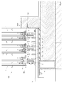
- FIG. 1 shows a vertical section through an inventive device 100 with a plurality of sliding elements 1, wherein in the section shown three sliding elements 1 can be seen.
- the sliding elements 1 are glass sliding elements.
- the sliding elements 1 are linearly displaceable in an upper region and in a lower region in the horizontal direction (i.e., in the direction normal to the plane of the page), i. the sliding elements are displaceable along their longitudinal extent.
- the displaceable storage takes place in the lower region of the sliding elements 1 by means of an external roller device 10, while the storage in the upper region, for example, takes place with a sliding bearing device 50.
- FIG. 2 shows the device 100 with the sliding elements 1, which are slidably mounted on the roller device 10, in a schematic plan view.
- the roller device 10 has several along the direction of displacement of the sliding element 1 arranged rollers 11, as shown in FIG. 2 can be seen.
- FIG. 3 now shows the device 100 in a vertical section through the device, in a lower region of the sliding elements 1 and in the region of the roller device 10th
- the roller device 10 is arranged below a floor upper edge FOK. By buried in the ground roller device a good accessibility is guaranteed. For good accessibility is also provided that the roller device 10 has longitudinally extending lamellae 12, between which slats 12, the rollers 11 of the roller device 10 are arranged. The roller device thus has a lamellar grid, formed by a bandage of lamellae running parallel to the sliding direction.
- Each of the three sliding elements 1 is slidably mounted by means of a separate rail 4 on a plurality of rollers 4 arranged one behind the other.
- the upper edges 11 "(see, eg Figure 4,4a ) of the rollers 11 of the roller device 10 are below the upper floor edge FOK, where it is as shown of particular advantage, if the rollers are not on the upper edge of the laminate laminate OKL (see FIG. 3 ) stand out.
- Adjacent rollers 11 are rotatably mounted on a common, rigid shaft / axis 14, preferably ball-bearing mounted.
- the shaft 14 itself is rigidly attached to the slats.
- the slats can be easily attached to a substructure.
- the cross members act as spacers to the substructure, whereby a problem-free drainage can take place.
- the three sliding elements 1 are designed as glass sliding elements and each consist of two outer side surfaces or glass panes 1a, 1b and a middle glass pane 1c.
- the intermediate disc 1c protrudes less far down than the two outer discs 1a, 1b.
- the discs 1a, 1b, 1c are held in a known manner by means of spacer elements 70 at a distance from each other.
- All three sliding element 1 shown are mounted by means of a rail 4 on the associated rollers 11, wherein the rail 4 is mounted respectively on the underside 2 of the sliding element 1; also be on the FIG. 4 refer, which shows the left sliding element 1 with removed fastener 3.
- Each sliding element 1 now has, on its underside 2 facing the roller device 10, a fastening element 3 for fastening the at least one rail 4 to the underside 2 of the sliding element 1.
- the fastening element 3 of the left sliding element (see also FIG. 4 ) is integrally formed with the rail 4, while in the middle and right sliding element, the fastening element and the rail are formed separately.
- the underside 2 of a sliding element 1 has a deviating from a continuous plane shape, namely the bottom 2 of a glass sliding element 1 from the two bottom sides 2 'of the glass sheets 1a, 1b and (in those areas where a spacer element 70) is provided from the outer side or faces 2 "of the spacer element 70, as well as from the underside of the slide 1c, as well as a part of the inner surfaces of the discs 1a, 1b and the side surfaces of the disc 1c protruding into the region 21.
- the fastener 3 is connected to the bottom 2 of the sliding element 1 at least partially positively and closes at the two side surfaces 1a, 1b of the sliding element 1 flush.
- Flushing means that the outer surface of the side surfaces 1a, 1b and the outer sides of the fastening element 3 lie in a common plane.
- the fastener is not in the sliding element 1 on the side surfaces 1a, 1b and is connected only at the bottom with the sliding element, so does not affect the side surfaces over. Thereby, the sliding element can be kept slim and the fastener does not widen the sliding element.
- the frame can be optically very narrow in the lower area.
- the fastener is - after installation - part of the edge bond of the sliding element and is preferably flush mounted in the edge seal.
- the fastening element 3 makes contact with the underside 2 at least in the edge regions 2 ', ie in the example shown on the undersides 2' of the glass panes 1a, 1b of the sliding element 1.
- the adhesive 90 is also clearly visible in the region between the disks 1a, 1b, so that the outer disks 1a, 1b are in each case tightly connected to the middle disk 1c.
- the glass sliding element is held together stably and in particular, the fastening element can also serve as fall protection for the glass surfaces 1a, 1b of the sliding glass element.
- the fastener may directly contact the underside of the contact area (and, e.g., mechanical connection such as by screws or bolts) or the fastener may be adhesively bonded to the underside in the contact area;
- the term "contact” thus also includes that between the bottom and fastener, an adhesive may be provided.
- FIG. 3 is shown in all variants, that the fastening element 3 is bonded to the underside 2, the adhesive layer between the fastening element 3 and the sliding element 1 is designated by the reference numeral 90.
- a (horizontal) gap which is filled with adhesive 90, so that a continuous, flush outer surface (outer surface of the discs 1a, 1b, adhesive 90th , Outer surface of the fastening element 3).
- the fastening element forms an edge bond with the outer glass panes or the outer glass panes are connected to one another by means of the fastening element in an edge bond.
- the fastening element can thus be considered in the assembled state as part of the sliding element.
- the sliding element 1 is mounted vertically on the fastening element 3 and thus standing on the rail 4.
- the fastening element 3 preferably contacts the underside 2 of the sliding element 1 along its entire longitudinal extent.
- the underside of the sliding element in the event that the spacer elements extend 70 (70 ') over the entire longitudinal extent of the sliding element, a quasi-continuous underside.
- spacer elements are provided only selectively, in the areas between the spacers thus there is no continuous bottom, but the sliding elements is initially "open” and is only by introducing the adhesive 90, which also acts as a seal, and the fastener completed.
- the adhesive is as far as necessary, usually introduced approximately up to the level of the underside of the spacer elements.
- the at least one intermediate disk 1c protrudes less far downwards than the two outer disks 1a, 1b.
- the resulting free space between the two outer disks 1a, 1b forms a groove 21 extending along the longitudinal extent on the underside 2 of the sliding element 1, and the fastening element 3 can project into this groove 21 with a section 3a.
- the sliding element 1 is supported on the fastening element 3 via the groove 21.
- the fastening element 3 contacts the underside of the sliding element 1 in the edge regions; but it can also be provided that the fastening element additionally contacted in the groove, the underside of the sliding element over the entire surface, so that there is a full-surface connection with the entire bottom.
- the actual connection can be done by means of screws, bolts etc or preferably by means of (elastic) adhesive, a combination of these connection possibilities is conceivable.
- the lower edge of the sliding elements is in the illustrated embodiment ( FIG. 3, 4 ) formed as a U-shaped stepped fold, in which a hat-shaped fastening element, preferably made of anodized aluminum, is glued. Between the glass edge of the middle pane 1c and the fastening element 3 punctiform intermediate layers of plastic (not shown) can be introduced, via which the load transfer of the glass element takes place.
- the hat flanges of the profile can be made very delicate. They form the mechanical fall protection for the two outer panes and can simultaneously serve as a carrier of a sealing profile on the inside or as edge protection for the glass element on the outside.
- the fastener 3 made of a metal, preferably made of anodized aluminum.
- the fastener 3 and the rail 4 are made in one piece.
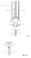
- the fastening element 3 can also be formed, for example, from GFRP (glass fiber reinforced plastic), as shown in the middle.
- the fastener 3 has a groove into which the - preferably metallic - rail 4 is inserted.
- the rail 4 is secured in the groove in the longitudinal direction against displacement.
- the fastening element 3 is formed from two GRP plates (for example extruded GRP), the rail 4 is screwed by means of a fastening element, for example a screw 105, through the FRP plate.
- a fastening element for example a screw 105
- FIGS. 5 and 6 show yet another variant of the invention, here the example of a double glazing, this variant is just as well suited for 3- or multiple glazing.
- the two outer discs 1a, 1b are held by means of spacers 70 'at a distance from each other.
- the sliding element 1 has on its underside 2 in the edge regions, to the side surfaces 1 a, 1 b in each case at least one extending in the longitudinal direction chamfer 22, wherein the fastener 3, the underside 2 of the sliding element 1 at least in the region of the chamfered area 22 contacted over the entire surface or connected to this area.
- the connection is made by means of a preferably elastic adhesive layer 90 analogous to the embodiments FIG. 3 and Figures 4 and 4a , As well as in the Figure 3 - 4a shown Embodiments also serve in the embodiment according to FIGS. 5 and 6 the adhesive 90 as a seal for sealing the underside of the sliding element. 1
- adhesive 90 for example, silicone, such as a two-component silicone is used.
- the underside of the sliding element facing surface of the fastener has for this purpose a corresponding configuration, with rising towards the edge, preferably flat trained cheek areas 3 ', by means of which the fastener 3 engages around the bottom in the chamfered area 22, without over the side surfaces 1a, 1b to face.
- the fastening element 3 makes contact with the underside 2 over the whole area in the area 2 'of the underside of the panes 1a, 1b (the bonding by means of adhesive 90 takes place in the region of the chamfer 22 on the glass panes 1a, 1b) and preferably also on the outer surfaces 2 "of the or Spacer 70 'is therefore preferably a "full-surface" (as far as just one surface is present, see above) bonding of the fastener provided with the underside of the sliding element.
- the rail 4 by means of which the sliding element 1 is mounted on the rollers 11 of the roller device, has a corresponding profile, with which it cooperates with the rolling surfaces of the rollers 11.
- the rails 4 have a significantly smaller width / transverse extent than the fastening element 4 or as the width of the underside of the sliding element.
- the distances between the slats 12 can be kept small and do not have to be as wide as or wider than the sliding element, as in the prior art, but can e.g. only half as wide or only one third as wide as the width of the sliding element.
- the rails 4 are mounted centrally in relation to the fastening element 3 on this or connected thereto.
- FIGS. 4 and 6 show a first embodiment of the rolling surfaces of the rollers 11.
- the rollers 11 have two bevelled outer rolling surfaces 11 ', which converge and end in two separate tips 11'.
- FIG. 4a shows a role with a fundamentally identical structure as those in FIG. 4 or 6, with the difference that here the rolling surfaces 11 'are arranged on the inside and converge, for example, pointed.
- the rail 4 engages with its converging profile in the groove 11 thus formed in the rollers and lies with the profile surfaces 4 'form-fitting manner on the rolling surfaces 11'a.
- FIG. 5 shows a variant in which the rolling surfaces 11 'in an edge, preferably pointed, converge, the rail 4 surrounds the two rolling surfaces and rests on these form-fitting manner.
- the rail 4 is thus on the tapered running surfaces 11 'of the rollers 11.
- the rails and rollers have a profile, for example in the form of a rectangular groove, a V-groove or an outside chamfer.
- the rail profile surrounds the rollers or engages in the converging running surfaces and rests on these.
- the rail and thus the sliding element firmly - especially in interaction with the storage in the upper area - secured against lateral loosening of the rollers or lateral tilting.
- the rails protrude down over the sliding element.
Abstract
Description
Die Erfindung betrifft eine Vorrichtung zum horizontalen Linearverschieben eines oder mehrerer Schiebeelemente, z.B. von Schiebeelementen in Form eines Glaselementes oder eines Wandelementes, wobei das Schiebeelement in einem oberen Bereich und in einem unteren Bereich in horizontaler Richtung linear verschiebbar gelagert ist, und wobei die verschiebbare Lagerung im unteren Bereich eines Schiebeelementes mittels einer externen Rollenvorrichtung erfolgt, wobei die Rollenvorrichtung mehrere entlang der Verschieberichtung des Schiebelementes angeordnete Rollen aufweist, auf welchen das Schiebeelement mittels zumindest einer Schiene gelagert ist, welche zumindest eine Schiene an der Unterseite des Schiebeelementes angebracht ist, wobei das Schiebeelement an seiner der Rollenvorrichtung zugewandten Unterseite zumindest ein Befestigungselement zum Befestigen der zumindest einen Schiene an der Unterseite des Schiebeelementes aufweistThe invention relates to a device for horizontal linear displacement of one or more sliding elements, e.g. sliding elements in the form of a glass element or a wall element, wherein the sliding element is linearly displaceably mounted in an upper region and in a lower region in the horizontal direction, and wherein the displaceable mounting in the lower region of a sliding element by means of an external roller device, wherein the roller device more along the direction of displacement of the sliding element arranged rollers, on which the sliding element is mounted by means of at least one rail, which at least one rail is attached to the underside of the sliding element, wherein the sliding element on its side facing the roller device at least one fastening element for securing the at least one rail has at the bottom of the sliding element
In der zeitgenössischen Architektur besteht ein großer Bedarf an großflächigen, boden- und deckenbündigen Schiebeelemente, etwa in Form von Glasschiebewänden, um öffenbare Übergänge von innen nach außen zu schaffen, z. B. von einem Wohnraum auf eine Terrasse.In contemporary architecture, there is a great need for large, flush floor and ceiling sliding elements, such as in the form of sliding glass walls to create openable transitions from the inside out, for. B. from a living room to a terrace.
Die Rahmen der dabei verwendeten Glaselemente sollen so zart wie möglich ausgeführt werden, um den Lichteinfall nicht zu beeinträchtigen und die Leichtigkeit der Konstruktion zu unterstreichen. Auch die Schienenkonstruktion soll optisch möglichst wenig in Erscheinung treten, bodenbündig und gut begehbar sein. Neben diesen formalen Anforderungen bestehen heute auch hohe Anforderungen an Dichtheit und Wärmedämmwerte solcher Schiebeanlagen.The frames of the glass elements used should be as delicate as possible, so as not to interfere with the light and to emphasize the ease of construction. The rail construction should visually appear as little as possible, flush with the floor and easy to walk on. In addition to these formal requirements, today there are also high demands on the tightness and thermal insulation values of such sliding systems.
Die große Mehrzahl der derzeit bekannten Glasschiebetürsysteme weisen, wie z. B. in der
Die derzeit bekannten Führungssysteme von Schiebetüren lassen sich im Wesentlichen in drei Gruppen aufteilen:The currently known guide systems of sliding doors can be essentially divided into three groups:
Am Schiebeelement sitzen oben zwei oder mehre Rollapparate, die in einer über dem Schiebeelement verlaufenen Schiene fahren. Im unteren Bereich werden solche Türen über eine Gleitführung gehalten. Solche Konstruktionen haben den Vorteil, dass die Bodeneinbauten unaufwendig sind. Sie können jedoch aus Gewichtsgründen nicht für große Glaselemente verwendet werden.At the top of the sliding element, two or more roll apparatuses, which travel in a rail running over the sliding element, are seated at the top. In the lower part of such doors are held on a sliding guide. Such constructions have the advantage that the floor installations are inexpensive. However, they can not be used for large glass elements for weight reasons.
Bei dieser Variante, wie sie z. B. in der
Nachteilig ist bei dieser Konstruktion, dass im Bodenbereich sehr breite Nuten entstehen, besonders bei mehrgleisigen Anlagen und der Verwendung von Dreifach-Isolierglaselementen. Diese Nuten können verschmutzen, das Wasser kann sich in ihnen sammeln und sie sind unbequem zu begehen.The disadvantage of this construction is that very wide grooves occur in the floor area, especially in multi-track installations and the use of triple insulating glass elements. These grooves can become dirty, the water can collect in them and they are uncomfortable to commit.
In der
In der
Es ist eine Aufgabe der Erfindung, eine hinsichtlich der oben angesprochenen Problemstellungen verbesserte Vorrichtung zum Verschieben von Schiebeelementen zu schaffen.It is an object of the invention to provide an improved device for shifting sliding elements in view of the above-mentioned problems.
Diese Aufgabe wird mit einer eingangs erwähnten Vorrichtung dadurch gelöst, dass erfindungsgemäß die Unterseite des Schiebeelementes eine von einer durchgehenden Ebene abweichende Gestalt aufweist, und wobei das zumindest eine Befestigungselement mit der Unterseite des Schiebeelementes zumindest bereichsweise formschlüssig verbunden ist, und wobei das zumindest eine Befestigungselement an den beiden Seitenflächen des Schiebeelementes bündig anschließt bzw. das Befestigungselement hinsichtlich seiner Querausdehnung seitlich nicht über die Seitenflächen hinausragt.This object is achieved with a device mentioned in the introduction, that according to the invention the underside of the sliding element has a different shape from a continuous plane, and wherein the at least one fastening element is at least partially positively connected to the underside of the sliding element, and wherein the at least one fastening element the two side surfaces of the sliding element flush adjoins or the fastener laterally does not protrude over the side surfaces in terms of its transverse extent.
Das Befestigungselement steht bei dem Schiebeelement nicht über dessen Seitenflächen über und ist nur an der Unterseite mit dem Schiebeelement verbunden, greift also nicht auf die Seitenflächen über. Dadurch kann das Schiebelement schlank gehalten werden und das Befestigungselement verbreitert das Schiebeelement nicht. Der Rahmen kann dadurch im unteren Bereich optisch sehr schmal oder völlig unsichtbar ausfallen.The fastener is not on the sliding elements over its side surfaces and is connected only at the bottom with the sliding element, so does not affect the side surfaces over. Thereby, the sliding element can be kept slim and the fastener does not widen the sliding element. The frame can be optically very narrow or completely invisible at the bottom.
Die Seitenflächen sind jene Flächen, welche vertikal stehen und in der Verschieberichtung liegen; im Gegensatz zu den Stirnflächen, welche normal zu der Verschieberichtung stehen. Die Seitenflächen sind z.B. Glasscheiben bei einem Glasschiebeelement.The side surfaces are those surfaces which are vertical and lie in the direction of displacement; in contrast to the end faces, which are normal to the direction of displacement. The side surfaces are e.g. Glass panes in a glass sliding element.
Das Befestigungselement ist - nach dem Einbau - Bestandteil des Randverbundes des Schiebeelementes und ist vorzugsweise flächenbündig in den Randverbund eingebaut.The fastener is - after installation - part of the edge bond of the sliding element and is preferably flush mounted in the edge seal.
Weiters wird die Aufgabe mit einer eingangs erwähnten Vorrichtung gelöst, bei welcher erfindungsgemäß die Rollenvorrichtung in Längsrichtung verlaufende Lamellen aufweist, zwischen welchen Lamellen die Rollen der Rollenvorrichtung angeordnet sind, wobei die zumindest eine Schiene zumindest teilweise in den Lamellenzwischenraum hineinragt.Furthermore, the object is achieved with a device mentioned in the introduction, in which according to the invention the roller device has longitudinally extending lamellae, between which lamellae the rollers of the roller device are arranged, wherein the at least one rail projects at least partially into the lamella intermediate space.
Die zumindest eine Schiene kann schmäler ausgebildet werden als das Befestigungselement und somit auch schmäler als das Schiebeelement an sich. Dadurch, dass die Schiene und nicht das gesamte Schiebeelement in den Zwischenraum zwischen den Lamellen ragt, können die unteren Außenkanten des Schiebeelements über der Oberkante des Lamellenrosts angeordnet werden.The at least one rail can be made narrower than the fastening element and thus also narrower than the sliding element per se. By doing that the rail and not the entire sliding element projects into the space between the slats, the lower outer edges of the sliding element can be arranged above the upper edge of the lamellar grid.
Auch in diesem Zusammenhang ist es natürlich, wie schon erörtert, von Vorteil, wenn die Unterseite des Schiebeelementes eine von einer durchgehenden Ebene abweichende Gestalt aufweist, und das zumindest eine Befestigungselement mit der Unterseite des Schiebeelementes zumindest bereichsweise formschlüssig verbunden ist, und wobei das zumindest eine Befestigungselement an den beiden Seitenflächen des Schiebeelementes bündig anschließt bzw. das Befestigungselement hinsichtlich seiner Querausdehnung seitlich nicht über die Seitenflächen hinausragt.Also in this context, it is of course, as already discussed, advantageous if the underside of the sliding element has a deviating from a continuous plane shape, and the at least one fastening element with the underside of the sliding element is at least partially positively connected, and wherein the at least one Fastening element flush adjoins the two side surfaces of the sliding element or the fastening element laterally does not protrude beyond the side surfaces in terms of its transverse extent.
Von Vorteil ist es, wenn das Befestigungselement die Unterseite zumindest im Randbereich bzw. den Randbereichen der Unterseite des Schiebeelementes flächig kontaktiert.It is advantageous if the fastening element contacts the underside at least in the edge region or the edge regions of the underside of the sliding element.
Die Bezeichnung "Randbereich" bezieht sich hier auf den Bereich, in welchem die Unterseite in die Seitenflächen übergeht (und nicht den Übergangsbereich Unterseite - Stirnflächen).The term "edge area" here refers to the area in which the underside merges into the side surfaces (and not the transition area bottom side - end faces).
Auf diese Weise wird das Schiebeelement stabil zusammengehalten und insbesondere kann das Befestigungselement auch als Absturzsicherung für die Seitenflächen des Schiebeelementes dienen.In this way, the sliding element is held together stably and in particular, the fastening element can also serve as fall protection for the side surfaces of the sliding element.
Das Befestigungselement kann im Kontaktbereich die Unterseite direkt kontaktieren (und z.B. mechanische Verbindung etwa mittels Schrauben oder Bolzen) oder das Befestigungselement ist im Kontaktbereich mit der Unterseite verklebt; der Begriff "kontaktieren' umfasst somit auch, dass zwischen Unterseite und Befestigungselement ein Kleber vorgesehen sein kann.The fastener may directly contact the underside of the contact area (and, e.g., mechanical connection such as by screws or bolts) or the fastener may be adhesively bonded to the underside in the contact area; The term "contact" thus also includes that between the bottom and fastener, an adhesive may be provided.
Hinsichtlich der erzielbaren Stabilität des Randverbundes ist es von Vorteil, wenn das Befestigungselement entlang seiner gesamten Längserstreckung die Unterseite des Schiebeelementes, zumindest in dem/ den Randbereichen, kontaktiert.With regard to the achievable stability of the edge bond, it is advantageous if the fastening element contacts the underside of the sliding element along its entire longitudinal extent, at least in the edge area (s).
Es kann auch vorgesehen sein, dass das Befestigungselement entlang seiner gesamten Quererstreckung die Unterseite des Schiebeelementes kontaktiert.It can also be provided that the fastening element contacts the underside of the sliding element along its entire transverse extent.
Der Begriff Längserstreckung bedeutet dabei "in Verschieberichtung" des Schiebeelementes, während "quer" bzw. " Quererstreckung" normal auf die Längserstreckung bedeutet.The term longitudinal extension means "in the direction of displacement" of the sliding element, while "transverse" or "transverse extent" means normal to the longitudinal extent.
Bei einer konkreten Variante der Erfindung ist vorgesehen, dass an der Unterseite zumindest eine Vertiefung in Form einer sich in Längsrichtung des Schiebelementes erstreckenden Nut vorgesehen ist, in welche zumindest eine Nut das Befestigungselement zumindest mit einem Befestigungselement-Abschnitt hineinragt.In a specific variant of the invention, it is provided that at least one depression in the form of a groove extending in the longitudinal direction of the sliding element is provided on the underside, into which at least one groove protrudes the fastening element at least with a fastening element section.
Das Schiebeelement ist über die Nut an dem Befestigungselement abgestützt. Das Befestigungselement kontaktiert die Unterseite des Schiebeelementes in den Randbereichen; es kann aber auch vorgesehen sein, dass das Befestigungselement zusätzlich in der Nut die Unterseite des Schiebeelementes vollflächig kontaktiert, sodass sich eine vollflächige Verbindung mit der gesamten Unterseite ergibt. Die eigentliche Verbindung kann mittels Schrauben, Bolzen etc erfolgen oder vorzugsweise mittels Kleber, auch eine Kombination dieser Verbindungsmöglichkeiten ist denkbar.The sliding element is supported on the fastening element via the groove. The fastening element contacts the underside of the sliding element in the edge regions; but it can also be provided that the fastening element additionally contacted in the groove, the underside of the sliding element over the entire surface, so that there is a full-surface connection with the entire bottom. The actual connection can be made by means of screws, bolts etc or preferably by means of adhesive, and a combination of these connection possibilities is conceivable.
Eine gute Verbindung zwischen dem Befestigungselement und dem Schiebeelement ergibt sich auch, wenn die Unterseite in ihren Randbereichen, zu den Seitenflächen hin jeweils zumindest eine in Längserstreckung verlaufende Fase oder jeweils zumindest einen Falz aufweist, wobei das Befestigungselement die Unterseite des Schiebeelementes zumindest im Bereich der Fasen bzw. Falze vollflächig kontaktiert bzw. mit diesem Bereich verbunden ist.A good connection between the fastening element and the sliding element also results if the underside has in its edge regions, towards the side surfaces at least one chamfer running in the longitudinal extension or at least one fold, wherein the fastening element at least in the region of the chamfers the underside of the sliding element or seams contacted over the entire surface or connected to this area.
Wie schon erwähnt, ist es zweckmäßig, wenn das Befestigungselement mit der Unterseite zumindest bereichsweise verklebt ist, und zwar zumindest an den Kontaktflächen im Randbereich. Grundsätzlich kann aber auch eine vollflächige Verklebung des Befestigungselementes mit der Unterseite des Schiebeelementes vorgesehen sein.As already mentioned, it is expedient if the fastening element is adhesively bonded to the underside at least in certain regions, specifically at least at the contact surfaces in the edge region. In principle, however, a full-surface bonding of the fastening element may be provided with the underside of the sliding element.
Wie eingangs schon erwähnt, ist das Befestigungselement in den Randverbund des Schiebeelements integriert und stellt außerdem eine Verbindung zu der Schiene her, auf welcher das Schiebeelement auf der Rollvorrichtung verschoben werden kann.As already mentioned, the fastening element is integrated in the edge connection of the sliding element and also establishes a connection to the rail on which the sliding element can be moved on the rolling device.
Dabei kann vorgesehen sein, dass an einem Befestigungselement die zumindest eine Schiene befestigt ist, d.h., dass die Schiene und Befestigungselement als getrennte Bauteile ausgebildet sind und bei der Montage der Vorrichtung zusammengesetzt werden, oder es ist mit Vorteil vorgesehen, dass Befestigungselement und Schiene einstückig ausgebildet sind. Die einteilige Ausgestaltung von Befestigungselement und Schiene (die Schiene ist in das Befestigungselement einstückig integriert) hat hinsichtlich Stabilität und Montageaufwand Vorteile, eine zweiteilige Ausgestaltung (Schiene und Befestigungselement als getrennte Bauteile ausgebildet) kann beispielsweise bei Nachrüstungen von Vorteil sein.It can be provided that the at least one rail is attached to a fastener, that is, that the rail and fastener are formed as separate components and are assembled during assembly of the device, or it is with Advantage provided that fastener and rail are integrally formed. The one-piece design of fastener and rail (the rail is integrally integrated into the fastener) has advantages in terms of stability and installation costs, a two-part design (rail and fastener formed as separate components), for example, in retrofits beneficial.
Ein weiterer Vorteil der Zweistückigkeit liegt darin, dass die Wärmedämmeigenschaften im Bereich des Befestigungselementes durch geeignete Wahl des Materials für das Befestigungselement deutlich verbessert werden können. Beispielsweise bei Verwendung von GFK als Material für das Befestigungselement (siehe auch noch weiter unten) kann die Klebefuge zwischen dem Befestigungselement und den Seitenflächen in Form von Glaselementen sehr schmal ausgebildet werden, da GFK und Glas einen sehr ähnlichen bzw. fast identischen Wärmeausdehnungskoeffizienten aufweisen. GFK ist allerdings als Schienenmaterial nicht geeignet, sodass sich eine zweiteilige Ausgestaltung als günstig erweist, bei welcher die Schiene selbst aus einem geeigneten Material gebildet ist oder zumindest die Außenseite der Schiene, wenn sie aus GFK einteilig mit dem Befestigungselement gefertigt ist, mit einer Verkleidung (= zweiter Teil) versehen ist.Another advantage of Zweistückigkeit is that the thermal insulation properties in the region of the fastener can be significantly improved by a suitable choice of the material for the fastener. For example, when using GRP as a material for the fastener (see also below), the adhesive joint between the fastener and the side surfaces in the form of glass elements can be made very narrow, since GRP and glass have a very similar or almost identical thermal expansion coefficient. However, GRP is not suitable as a rail material, so that proves to be a two-part design in which the rail itself is formed of a suitable material or at least the outside of the rail, if it is made of fiberglass in one piece with the fastener, with a covering ( = second part) is provided.
Von besonderem Vorteil ist es, wenn die zumindest eine Schiene eine geringere Breite/Querausdehnung aufweist als das Befestigungselement bzw. als die Breite der Unterseite des Schiebeelementes.It is particularly advantageous if the at least one rail has a smaller width / transverse extent than the fastening element or the width of the underside of the sliding element.
Aus Stabilitätsgründen ist es weiters von Vorteil, wenn die Schiene mittig in Bezug auf das Befestigungselement an diesem angebracht bzw. mit diesem verbunden ist.For stability reasons, it is further advantageous if the rail is mounted centrally in relation to the fastening element on this or connected thereto.
Weiters ist es von Vorteil, wenn die Rollenvorrichtung unterhalb einer Fußbodenoberkante angeordnet ist bzw. bis maximal auf Höhe der Fußbodenoberkante reicht.Furthermore, it is advantageous if the roller device is arranged below a floor top edge or extends to a maximum level with the floor top edge.
Durch die im Boden versenkte Rollenvorrichtung ist eine gute Begehbarkeit gewährleistet.By buried in the ground roller device a good accessibility is guaranteed.
Insbesondere ist dabei vorgesehen, dass die Oberkanten der Rollen der Rollenvorrichtung unterhalb der Fußbodenoberkante liegen.In particular, it is provided that the upper edges of the rollers of the roller device are below the floor level.
Zwecks guter Begehbarkeit und aus Gründen des Wetterschutzes ist es außerdem zweckmäßig, wenn die Rollenvorrichtung in Längsrichtung verlaufende Lamellen aufweist, zwischen welchen Lamellen die Rollen der Rollenvorrichtung angeordnet sind.For the purpose of good accessibility and for reasons of weather protection, it is also expedient if the roller device has lamellae extending in the longitudinal direction, between which lamellae the rollers of the roller device are arranged.
Die Rollenvorrichtung weist also einen Lamellenrost, gebildet durch einen Verband aus parallel zur Schieberichtung verlaufenen Lamellen auf.The roller device thus has a lamellar grid, formed by a bandage of lamellae running parallel to the sliding direction.
Dabei ist es insbesondere günstig, wenn die Rollen nicht über die Oberkante des Lamellenverbandes vor stehen.It is particularly advantageous if the rollers are not over the top of the lamellar Association before.
Es kann außerdem mit Vorteil vorgesehen sein, dass die Lamellen mittels unter den Lamellen verlaufenden Querträgern miteinander verbunden sind.It can also be advantageously provided that the slats are connected to each other by means of running under the slats cross members.
Über diese Querträger können die Lamellen einfach an einer Unterkonstruktion befestigt werden. Gleichzeitig wirken die Querträger als Abstandhalter zur Unterkonstruktion, wodurch eine problemlose Entwässerung erfolgen kann.About this cross beams, the slats can be easily attached to a substructure. At the same time, the cross members act as spacers to the substructure, whereby a problem-free drainage can take place.
Um einen guten seitlichen Halt des Schiebeelementes auf den Rollen gewährleisten zu können, ist vorteilhafterweise vorgesehen, dass die Rollen abgeschrägte Laufflächen aufweisen, auf welchen die zumindest eine Schiene mit ihrem Schienenprofil aufliegt, wobei vorzugsweise die Rollen zwei abgeschrägte, spitz zusammenlaufende Laufflächen aufweisen.In order to ensure a good lateral support of the sliding element on the rollers, it is advantageously provided that the rollers have tapered running surfaces on which rests the at least one rail with its rail profile, wherein preferably the rollers have two beveled, tapered running surfaces.
Prinzipiell lässt sich die Erfindung für beliebige Schiebewände einsetzen, besonders gut eignet sich die Erfindung aber für Glasschiebeelemente, etwa Isolierglaselemente, die als Türen, Fenster, Schiebewände u. dgl. verwendet werden können.In principle, the invention can be used for any sliding walls, but the invention is particularly well suited for glass sliding elements, such as insulating glass elements, as doors, windows, sliding walls u. Like. Can be used.
In diesem Zusammenhang ist es entsprechend vorgesehen, dass ein oder mehrere, vorzugsweise alle Schiebeelemente als Glasschiebeelemente, mit zumindest zwei oder mehr, insbesondere drei Glasscheiben, ausgebildet ist/sind.In this context, it is accordingly provided that one or more, preferably all sliding elements are designed as glass sliding elements, with at least two or more, in particular three glass panes, is / are.
Mit der Erfindung können Glasschiebeelemente mit nahezu beliebig großen Glasscheiben in Dreifachverglasung bodenbündig ausgeführt werden, wobei die Glasschiebeelemente ohne außen- und innenliegenden Rahmen und ohne breite Nuten im Bodenbereich auskommen. Bei dieser Ausführungsform ist vorgesehen, dass die beiden Seitenflächen von Glasscheiben gebildet sind, wobei das zumindest eine Befestigungselement die beiden Seitenflächen an ihrer Unterseite kontaktiert bzw. mit diesen verbunden ist.With the invention glass sliding elements with almost any size glass panes in triple glazing can be performed flush with the floor, the glass sliding elements without external and internal frame and without wide grooves in the bottom area. In this embodiment, it is provided that the two side surfaces are formed by glass sheets, wherein the at least one fastening element, the two side surfaces contacted on its underside or is connected thereto.
Schließlich ist es noch von Vorteil, wenn bei einem Drei- oder Mehrfachglas-Glasschiebeelement die zumindest eine Zwischenscheibe weniger weit nach unten ragt als die beiden äußeren Scheiben, und wobei das Befestigungselement mit zumindest einem Abschnitt in den zwischen den beiden äußeren Scheiben entstehenden Freiraum hineinragt.Finally, it is still advantageous if, in the case of a three-glass or multiple-glass sliding glass element, the at least one intermediate disk protrudes less far down than the two outer disks, and wherein the fastening element protrudes with at least one portion into the free space created between the two outer disks.
Im Folgenden ist die Erfindung an Hand der Zeichnung näher erläutert. In dieser zeigt
-
Fig. 1 einen Vertikalschnitt durch eine erfindungsgemäße Vorrichtung mit mehreren Schiebeelementen, -
Fig. 2 eine Draufsicht auf dieVorrichtung aus Figur 1 , -
Fig. 3 einen Vertikalschnitt durch eine beispielhafte Vorrichtung im Bodenbereich mit einer Darstellung von mehreren Realisierungen der Erfindung, -
Fig. 4 einen schematischen Vertikalschnitt durch eine weitere beispielhafte Vorrichtung im Bodenbereich, -
Fig. 4a ein beispielhaftes Detail Schiene - Rad, -
Fig. 5 einen schematischen Vertikalschnitt durch noch eine weitere beispielhafte Vorrichtung im Bodenbereich, und -
Fig. 6 einen schematischen Vertikalschnitt durch noch eine weitere beispielhafte Vorrichtung im Bodenbereich.
-
Fig. 1 a vertical section through a device according to the invention with a plurality of sliding elements, -
Fig. 2 a plan view of the deviceFIG. 1 . -
Fig. 3 FIG. 2 a vertical section through an exemplary device in the floor area with a representation of several implementations of the invention, FIG. -
Fig. 4 FIG. 2 shows a schematic vertical section through a further exemplary device in the floor area, FIG. -
Fig. 4a an exemplary detail rail - wheel, -
Fig. 5 a schematic vertical section through yet another exemplary device in the bottom area, and -
Fig. 6 a schematic vertical section through yet another exemplary device in the bottom area.
Die Schiebeelemente 1 sind in einem oberen Bereich und in einem unteren Bereich in horizontaler Richtung (d.h. in Richtung normal auf die Blattebene) linear verschiebbar gelagert ist, d.h. die Schiebeelemente sind entlang ihrer Längserstreckung verschiebbar.The sliding
Die verschiebbare Lagerung erfolgt im unteren Bereich der Schiebeelemente 1 mittels einer externen Rollenvorrichtung 10, während die Lagerung im oberen Bereich beispielsweise mit einer Gleitlagervorrichtung 50 erfolgt.The displaceable storage takes place in the lower region of the sliding
Die Rollenvorrichtung 10 weist dabei mehrere entlang der Verschieberichtung des Schiebelementes 1 angeordnete Rollen 11 aufweist, wie dies in
Aus instruktiven Gründen sind hier in einer Figur drei unterschiedliche Ausgestaltungen der Erfindung dargestellt; prinzipiell ist eine solche Mischung natürlich denkbar, in der Praxis wird aber in der Regel lediglich eine Art einer Befestigungselement-Schiene-Schiebeelement-Kombination zum Einsatz kommen.For instructive reasons, three different embodiments of the invention are shown in one figure; In principle, such a mixture is of course conceivable, but in practice only one type of fastener-rail-slide element combination will usually be used.
Wie zu erkennen ist, ist die Rollenvorrichtung 10 unterhalb einer Fußbodenoberkante FOK angeordnet. Durch die im Boden versenkte Rollenvorrichtung ist eine gute Begehbarkeit gewährleistet. Zwecks guter Begehbarkeit ist außerdem vorgesehen, dass die Rollenvorrichtung 10 in Längsrichtung verlaufende Lamellen 12 aufweist, zwischen welchen Lamellen 12 die Rollen 11 der Rollenvorrichtung 10 angeordnet sind. Die Rollenvorrichtung weist also einen Lamellenrost, gebildet durch einen Verband aus parallel zur Schieberichtung verlaufenen Lamellen auf.As can be seen, the
Jedes der drei Schiebeelemente 1 ist mittels einer eigenen Schiene 4 auf mehreren hintereinander angeordneten Rollen 4 verschiebbar gelagert.Each of the three sliding
Insbesondere ist dabei vorgesehen, dass die Oberkanten 11" (siehe z.B.
Nebeneinander liegende Rollen 11 sind auf einer gemeinsamen, starren Welle/Achse 14 drehbar, vorzugsweise kugelgelagert, angebracht. Die Welle 14 selbst ist starr an den Lamellen befestigt. Weiters können die Lamellen 12, wie in
In
Über diese Querträger können die Lamellen einfach an einer Unterkonstruktion befestigt werden. Gleichzeitig wirken die Querträger als Abstandhalter zur Unterkonstruktion, wodurch eine problemlose Entwässerung erfolgen kann.About this cross beams, the slats can be easily attached to a substructure. At the same time, the cross members act as spacers to the substructure, whereby a problem-free drainage can take place.
Die drei Schiebeelemente 1 sind als Glasschiebelemente ausgebildet und bestehen jeweils aus zwei äußeren Seitenflächen bzw. Glasscheiben 1a, 1b und einer mittleren Glassscheibe 1c. Die Zwischenscheibe 1c ragt dabei weniger weit nach unten als die beiden äußeren Scheiben 1a,1b.The three sliding
Die Scheiben 1a, 1b, 1c sind in bekannter Weise mittels Distanzelementen 70 in Abstand zueinander gehalten.The
Alle drei gezeigten Schiebeelement 1 sind mittels einer Schiene 4 auf den zugehörigen Rollen 11 gelagert ist, wobei die Schiene 4 jeweils an der Unterseite 2 des Schiebeelementes 1 angebracht ist; dazu sei auch auf die
Jedes Schiebeelement 1 weist nun an seiner der Rollenvorrichtung 10 zugewandten Unterseite 2 ein Befestigungselement 3 zum Befestigen der zumindest einen Schiene 4 an der Unterseite 2 des Schiebeelementes 1 auf.Each sliding
Das Befestigungselement 3 des linken Schiebeelementes (siehe auch
Wie in
Das Befestigungselement 3 ist dabei mit der Unterseite 2 des Schiebeelementes 1 zumindest bereichsweise formschlüssig verbunden und schließt an den beiden Seitenflächen 1a, 1b des Schiebeelementes 1 bündig an.The
Bündig bedeutet dabei, dass die Außenfläche der Seitenflächen 1a, 1b und die Außenseiten des Befestigungselementes 3 in einer gemeinsamen Ebene liegen.Flushing means that the outer surface of the side surfaces 1a, 1b and the outer sides of the
Das Befestigungselement steht bei dem Schiebeelement 1 nicht über dessen Seitenflächen 1a, 1b über und ist nur an der Unterseite mit dem Schiebeelement verbunden, greift also nicht auf die Seitenflächen über. Dadurch kann das Schiebelement schlank gehalten werden und das Befestigungselement verbreitert das Schiebeelement nicht. Der Rahmen kann dadurch im unteren Bereich optisch sehr schmal ausfallen.The fastener is not in the sliding
Das Befestigungselement ist - nach dem Einbau - Bestandteil des Randverbundes des Schiebeelementes und ist vorzugsweise flächenbündig in den Randverbund eingebaut.The fastener is - after installation - part of the edge bond of the sliding element and is preferably flush mounted in the edge seal.
Das Befestigungselement 3 kontaktiert flächig die Unterseite 2 zumindest in den Randbereichen 2', also in dem gezeigten Beispiel an den Unterseiten 2' der Glasscheiben 1a, 1b des Schiebeelementes 1. Vorzugsweise ist allerdings wie dies in
Auf diese Weise wird das Glasschiebeelement stabil zusammengehalten und insbesondere kann das Befestigungselement auch als Absturzsicherung für die Glasflächen 1a, 1b des Schiebeglaselementes dienen.In this way, the glass sliding element is held together stably and in particular, the fastening element can also serve as fall protection for the glass surfaces 1a, 1b of the sliding glass element.
Das Befestigungselement kann im Kontaktbereich die Unterseite direkt kontaktieren (und z.B. mechanische Verbindung etwa mittels Schrauben oder Bolzen) oder das Befestigungselement ist im Kontaktbereich mit der Unterseite verklebt; der Begriff "kontaktieren' umfasst somit auch, dass zwischen Unterseite und Befestigungselement ein Kleber vorgesehen sein kann.The fastener may directly contact the underside of the contact area (and, e.g., mechanical connection such as by screws or bolts) or the fastener may be adhesively bonded to the underside in the contact area; The term "contact" thus also includes that between the bottom and fastener, an adhesive may be provided.
In
Zwischen den Seitenflächen 1a, 1b bzw. den Glasscheiben 1a, 1b und dem Befestigungselement 3 befindet sich eine (horizontal verlaufende) Fuge, die mit Klebstoff 90 ausgefüllt ist, sodass sich eine durchgehend, bündige Außenfläche (Außenfläche der Scheiben 1a, 1b, Kleber 90, Außenfläche des Befestigungselementes 3) ergibt.Between the side surfaces 1a, 1b or the
Das Befestigungselement bildet mit den äußeren Glassscheiben einen Randverbund bzw. sind die äußeren Glasscheiben mittels des Befestigungselementes in einem Randverbund miteinander verbunden.The fastening element forms an edge bond with the outer glass panes or the outer glass panes are connected to one another by means of the fastening element in an edge bond.
Das Glaselement (bzw. das Schiebeelement allgemein) und das Befestigungselement sind somit durchgehend formschlüssig verbunden, das Befestigungselement kann somit im zusammengebauten Zustand als Teil des Schiebeelementes betrachtet werden.The glass element (or the sliding element in general) and the fastening element are thus connected positively in a continuous manner, the fastening element can thus be considered in the assembled state as part of the sliding element.
Das Schiebeelement 1 ist stehend auf dem Befestigungselement 3 und somit stehend auf der Schiene 4 angebracht.The sliding
Das Befestigungselement 3 kontaktiert vorzugsweise entlang seiner gesamten Längserstreckung die Unterseite 2 des Schiebeelementes 1.The
Außerdem ergibt sich eine stabile Verbindung insbesondere dann, wenn wie in
Grundsätzlich ist dabei anzumerken, dass die Unterseite des Schiebeelementes für den Fall, dass sich die Distanzelemente 70 (70') über die gesamte Längserstreckung des Schiebeelementes erstrecken, eine quasi durchgehend Unterseite ist. Natürlich kann auch vorgesehen sein, dass Distanzelemente nur punktuell vorgesehen sind, in den Bereichen zwischen den Distanzhaltern liegt somit keine durchgehende Unterseite vor, sondern das Schiebelemente ist vorerst "offen" ausgebildet und wird erst durch Einbringen des Klebers 90, welcher auch als Dichtung fungiert, und des Befestigungselementes abgeschlossen. In den Bereichen zwischen den Distanzhaltern wird der Kleber soweit wie notwendig, in der Regel ungefähr bis auf Höhe der Unterseite der Distanzelemente eingebracht.In principle, it should be noted that the underside of the sliding element in the event that the spacer elements extend 70 (70 ') over the entire longitudinal extent of the sliding element, a quasi-continuous underside. Of course, it can also be provided that spacer elements are provided only selectively, in the areas between the spacers thus there is no continuous bottom, but the sliding elements is initially "open" and is only by introducing the adhesive 90, which also acts as a seal, and the fastener completed. In the areas between the spacers, the adhesive is as far as necessary, usually introduced approximately up to the level of the underside of the spacer elements.
Wie schon erwähnt, ist es von Vorteil, wenn, wie in
Das Schiebeelement 1 ist über die Nut 21 an dem Befestigungselement 3 abgestützt. Das Befestigungselement 3 kontaktiert die Unterseite des Schiebeelementes 1 in den Randbereichen; es kann aber auch vorgesehen sein, dass das Befestigungselement zusätzlich in der Nut die Unterseite des Schiebeelementes vollflächig kontaktiert, sodass sich eine vollflächige Verbindung mit der gesamten Unterseite ergibt. Die eigentliche Verbindung kann mittels Schrauben, Bolzen etc erfolgen oder vorzugsweise mittels (elastischen) Klebers, auch eine Kombination dieser Verbindungsmöglichkeiten ist denkbar.The sliding
Der untere Rand der Schiebeelemente ist bei der gezeigten Ausführungsform (
Noch einmal auf
Das Befestigungselement 3 kann aber beispielsweise auch aus GFK (Glasfaserverstärkter Kunststoff) gebildet sein, wie in der Mitte gezeigt. Das Befestigungselement 3 weist eine Nut auf, in welche die - vorzugsweise wieder metallische - Schiene 4 eingeschoben wird. Die Schiene 4 ist in der Nut in Längsrichtung gegen Verschieben gesichert.However, the
Ganz rechts ist eine Variante gezeigt, bei der das Befestigungselement 3 aus zwei GFK-Platten (z.B. stranggepreßtes GFK) gebildet ist, die Schiene 4 ist mittels eines Befestigungselementes, beispielsweise einer Schraube 105, durch die GFK-Platte angeschraubt.On the right is shown a variant in which the
Die beiden äußeren Scheiben 1a, 1b sind mittels Distanzhalter 70' in Abstand zueinander gehalten.The two
Das Schiebeelement 1 weist an seiner Unterseite 2 in den Randbereichen, zu den Seitenflächen 1a, 1b hin jeweils zumindest eine in Längserstreckung verlaufende Fase 22 auf, wobei das Befestigungselement 3 die Unterseite 2 des Schiebeelementes 1 zumindest im Bereich des abgefasten Bereiches 22 vollflächig kontaktiert bzw. mit diesem Bereich verbunden ist. Die Verbindung erfolgt mittels einer vorzugsweise elastischen Klebeschicht 90 analog zu den Ausführungsformen aus
Als Kleber 90 wird beispielsweise Silikon, etwa ein Zweikomponenten-Silikon verwendet.As adhesive 90, for example, silicone, such as a two-component silicone is used.
Die der Unterseite des Schiebeelementes zugewandte Fläche des Befestigungselementes weist dazu eine entsprechende Ausgestaltung auf, mit zu Rand hin ansteigenden, vorzugsweise eben ausgebildeten Wangenbereichen 3', mittels welchen das Befestigungselement 3 die Unterseite im abgefasten Bereich 22 umgreift, ohne dabei über die Seitenflächen 1a, 1b überzustehen.The underside of the sliding element facing surface of the fastener has for this purpose a corresponding configuration, with rising towards the edge, preferably flat trained cheek areas 3 ', by means of which the
Das Befestigungselement 3 kontaktiert die Unterseite 2 vollflächig im Bereich 2' der Unterseite der Scheiben 1a, 1b (die Verklebung mittels Kleber 90 erfolgt also im Bereich der Abfasung 22 an den Glassscheiben 1a, 1b) und vorzugsweise auch an den Außenflächen 2" des oder der Abstandhalter 70'. Vorzugsweise ist also eine "vollflächige" (soweit eben eine Fläche vorhanden ist, siehe oben) Verklebung des Befestigungselementes mit der Unterseite des Schiebeelementes vorgesehen.The
Die Schiene 4, mittels welcher das Schiebeelement 1 auf den Rollen 11 der Rollenvorrichtung gelagert ist, weist ein entsprechendes Profil auf, mit welchem sie mit den Rollflächen der Rollen 11 zusammenwirkt.The
Die Schienen 4 weisen eine deutlich geringere Breite/Querausdehnung auf als das Befestigungselement 4 bzw. als die Breite der Unterseite des Schiebeelementes.The
Dadurch können die Abstände zwischen den Lamellen 12 klein gehalten werden und müssen nicht, wie im Stand der Technik, so breit wie oder breiter als das Schiebeelement sein, sondern können z.B. lediglich halb so breit oder nur ein Drittel so breit sein wie die Breite des Schiebeelementes.Thereby, the distances between the
Die Schienen 4 sind mittig in Bezug auf das Befestigungselement 3 an diesem angebracht bzw. mit diesem verbunden.The
Die
Auf diesen beiden Rollflächen 11' liegt die Schiene 4 mit entsprechend ausgebildeten, ebenen Profilflächen 4' formschlüssig auf, d.h. die Profilflächen 4' umgreifen die Rolle 11 an deren außenliegenden Rollflächen 11'.On these two rolling surfaces 11 'is the
Die Schiene 4 liegt also auf den abgeschrägten Laufflächen 11' der Rollen 11 auf. Die Schienen und Rollen weisen ein Profil beispielsweise in Form einer rechteckigen Nut, einer V-Nut oder einer außenseitigen Abfasung auf.The
Das Schienenprofil umgreift die Rollen oder greift in die zusammenlaufenden Laufflächen ein und liegt auf diesen auf. Dadurch ist die Schiene und somit das Schiebeelement fest - insbesondere in Zusammenspiel mit der Lagerung im oberen Bereich - gegen ein seitliches Lösen von den Rollen oder ein seitliches Kippen gesichert.The rail profile surrounds the rollers or engages in the converging running surfaces and rests on these. As a result, the rail and thus the sliding element firmly - especially in interaction with the storage in the upper area - secured against lateral loosening of the rollers or lateral tilting.
Die Schienen stehen nach unten über das Schiebeelement hervor.The rails protrude down over the sliding element.
Claims (15)
und wobei die verschiebbare Lagerung im unteren Bereich eines Schiebeelementes (1) mittels einer externen Rollenvorrichtung (10) erfolgt,
wobei die Rollenvorrichtung (10) mehrere entlang der Verschieberichtung des Schiebelementes (1) angeordnete Rollen (11) aufweist,
auf welchen das Schiebeelement (1) mittels zumindest einer Schiene (4) gelagert ist, welche zumindest eine Schiene (4) an der Unterseite (2) des Schiebeelementes (1) angebracht ist,
wobei das Schiebeelement (1) an seiner der Rollenvorrichtung (10) zugewandten Unterseite (2) zumindest ein Befestigungselement (3) zum Befestigen der zumindest einen Schiene (4) an der Unterseite (2) des Schiebeelementes (1) aufweist,
dadurch gekennzeichnet, dass
die Unterseite des Schiebeelementes (1) eine von einer durchgehenden Ebene abweichende Gestalt aufweist, und wobei
das zumindest eine Befestigungselement (3) mit der Unterseite (2) des Schiebeelementes (1) zumindest bereichsweise formschlüssig verbunden ist, und wobei
das zumindest eine Befestigungselement (3) an den beiden Seitenflächen (1a, 1b) des Schiebeelementes (1) bündig anschließt bzw. das Befestigungselement (3) hinsichtlich seiner Querausdehnung seitlich nicht über die Seitenflächen (1a,1b) hinausragt.Device (100) for horizontal linear displacement of one or more sliding elements (1), eg of sliding elements (1), characterized in that in the form of a glass element or a wall element, wherein the sliding element (1) in an upper region and in a lower region in horizontal Direction is linearly displaceable,
and wherein the displaceable mounting in the lower region of a sliding element (1) takes place by means of an external roller device (10),
wherein the roller device (10) has a plurality of rollers (11) arranged along the displacement direction of the sliding element (1),
on which the sliding element (1) is mounted by means of at least one rail (4), which at least one rail (4) is attached to the underside (2) of the sliding element (1),
wherein the sliding element (1) has on its underside (2) facing the roller device (10) at least one fastening element (3) for fastening the at least one rail (4) to the underside (2) of the sliding element (1),
characterized in that
the underside of the sliding element (1) has a different shape from a continuous plane, and wherein
the at least one fastening element (3) is connected to the underside (2) of the sliding element (1) in a form-fitting manner at least in regions, and wherein
the at least one fastening element (3) adjoins flush on the two side surfaces (1a, 1b) of the sliding element (1) or the fastening element (3) does not protrude laterally beyond the lateral surfaces (1a, 1b) with respect to its transverse extent.
Applications Claiming Priority (1)
| Application Number | Priority Date | Filing Date | Title |
|---|---|---|---|
| AT10472011A AT511726B1 (en) | 2011-07-15 | 2011-07-15 | DEVICE FOR MOVING A SLIDING ELEMENT |
Publications (3)
| Publication Number | Publication Date |
|---|---|
| EP2546448A2 true EP2546448A2 (en) | 2013-01-16 |
| EP2546448A3 EP2546448A3 (en) | 2014-11-05 |
| EP2546448B1 EP2546448B1 (en) | 2016-12-21 |
Family
ID=46578854
Family Applications (1)
| Application Number | Title | Priority Date | Filing Date |
|---|---|---|---|
| EP12176290.0A Not-in-force EP2546448B1 (en) | 2011-07-15 | 2012-07-13 | Device for pushing a slide element |
Country Status (2)
| Country | Link |
|---|---|
| EP (1) | EP2546448B1 (en) |
| AT (1) | AT511726B1 (en) |
Cited By (5)
| Publication number | Priority date | Publication date | Assignee | Title |
|---|---|---|---|---|
| WO2017051307A1 (en) * | 2015-09-21 | 2017-03-30 | Go Technology S.R.L. | Sash for doors or windows |
| CH714348A1 (en) * | 2017-11-17 | 2019-05-31 | Troesch Glas Ag | Component and method for manufacturing a device. |
| US10641033B2 (en) | 2015-09-21 | 2020-05-05 | Go Technology S.R.L. | Sash for doors or windows and door or window obtained with the sash |
| WO2020264085A1 (en) * | 2019-06-28 | 2020-12-30 | Glazcon Production, Inc. | Panel system for sliding doors or panels |
| EP3859117A1 (en) * | 2020-01-29 | 2021-08-04 | Christian Michels | Push window device |
Citations (3)
| Publication number | Priority date | Publication date | Assignee | Title |
|---|---|---|---|---|
| WO1994017275A1 (en) | 1993-01-26 | 1994-08-04 | Eric Joray | Sliding window or glass door |
| US5671501A (en) | 1996-06-03 | 1997-09-30 | Laramie; Abraham J. | Self cleaning sliding door bottom track assembly |
| EP1353034A2 (en) | 2002-04-10 | 2003-10-15 | Beat GUHL | Sliding door frame construction |
Family Cites Families (4)
| Publication number | Priority date | Publication date | Assignee | Title |
|---|---|---|---|---|
| GB396283A (en) * | 1932-12-30 | 1933-08-03 | Ziehl Gustav | Improvements in or relating to rolling friction bearings for sliding doors and windows |
| US2527740A (en) * | 1948-03-18 | 1950-10-31 | Garden City Plating & Mfg Co | Sliding door support |
| CH445087A (en) * | 1966-09-26 | 1967-10-15 | Vedette Ets | Sliding window |
| DE10052314A1 (en) * | 2000-10-21 | 2002-05-02 | Pauli & Sohn Gmbh Metallwaren | Glass element e.g. as sliding door has metal fitting strips with counter profiles on inner edge to match profiles on edges of glass pane for neat connection |
-
2011
- 2011-07-15 AT AT10472011A patent/AT511726B1/en not_active IP Right Cessation
-
2012
- 2012-07-13 EP EP12176290.0A patent/EP2546448B1/en not_active Not-in-force
Patent Citations (3)
| Publication number | Priority date | Publication date | Assignee | Title |
|---|---|---|---|---|
| WO1994017275A1 (en) | 1993-01-26 | 1994-08-04 | Eric Joray | Sliding window or glass door |
| US5671501A (en) | 1996-06-03 | 1997-09-30 | Laramie; Abraham J. | Self cleaning sliding door bottom track assembly |
| EP1353034A2 (en) | 2002-04-10 | 2003-10-15 | Beat GUHL | Sliding door frame construction |
Cited By (8)
| Publication number | Priority date | Publication date | Assignee | Title |
|---|---|---|---|---|
| WO2017051307A1 (en) * | 2015-09-21 | 2017-03-30 | Go Technology S.R.L. | Sash for doors or windows |
| US10378270B2 (en) | 2015-09-21 | 2019-08-13 | Go Technology S.R.L. | Sash for doors or windows |
| US10641033B2 (en) | 2015-09-21 | 2020-05-05 | Go Technology S.R.L. | Sash for doors or windows and door or window obtained with the sash |
| CH714348A1 (en) * | 2017-11-17 | 2019-05-31 | Troesch Glas Ag | Component and method for manufacturing a device. |
| AT520668A3 (en) * | 2017-11-17 | 2020-01-15 | Troesch Glas Ag | Component and method for producing a component |
| WO2020264085A1 (en) * | 2019-06-28 | 2020-12-30 | Glazcon Production, Inc. | Panel system for sliding doors or panels |
| US11492832B2 (en) | 2019-06-28 | 2022-11-08 | Glazcon Production, Inc. | Panel system for sliding doors or panels |
| EP3859117A1 (en) * | 2020-01-29 | 2021-08-04 | Christian Michels | Push window device |
Also Published As
| Publication number | Publication date |
|---|---|
| AT511726B1 (en) | 2013-05-15 |
| EP2546448A3 (en) | 2014-11-05 |
| EP2546448B1 (en) | 2016-12-21 |
| AT511726A1 (en) | 2013-02-15 |
Similar Documents
| Publication | Publication Date | Title |
|---|---|---|
| EP2546448B1 (en) | Device for pushing a slide element | |
| EP3225771B1 (en) | Threshold for a sliding door and sliding door | |
| EP1431501A2 (en) | Sliding door assembly | |
| EP2327855B1 (en) | Insulating glass unit and bearing construction with at least one such insulating glass unit | |
| EP0147502A1 (en) | Roof with at least a movable roof part | |
| DE2023536B2 (en) | Skeleton frame supported curtain wall - has insulating connector lugs with ends in grooves and joining outside profiles | |
| EP2372032B1 (en) | Partition wall made of transparent wall elements | |
| DE3446150A1 (en) | Partition with horizontally displaceable panels | |
| DE202007006127U1 (en) | sliding element | |
| DE3939619C1 (en) | ||
| CH702394B1 (en) | Sliding wall with at least two wings. | |
| DE202008004373U1 (en) | Elemented post-and-beam facade | |
| DE102014103950A1 (en) | Insulating element for façade or light roof constructions | |
| EP3219895B1 (en) | Sliding door assembly and sliding leaf of a sliding door assembly | |
| DE3812819C2 (en) | Wooden window | |
| AT13115U1 (en) | SECTIONAL | |
| DE10011576B4 (en) | Window or door frames for containers or the like | |
| CH705728B1 (en) | Display device for the parallel display of a roof or facade composite glass unit. | |
| AT510161B1 (en) | DEVICE FOR CONNECTING WALL PARTS | |
| EP2327295A2 (en) | Greenhouse | |
| DE202007018281U1 (en) | Disconnectors device | |
| EP4012146A1 (en) | Door leaf, hollow plastic profile and method for the subsequent production of a door leaf | |
| EP2767661A2 (en) | Building door | |
| AT403179B (en) | Glass roof | |
| CH714450B1 (en) | Barrier-free window sill, window sash for use with this window sill and window arrangement with this window sill and this window sash. |
Legal Events
| Date | Code | Title | Description |
|---|---|---|---|
| PUAI | Public reference made under article 153(3) epc to a published international application that has entered the european phase |
Free format text: ORIGINAL CODE: 0009012 |
|
| AK | Designated contracting states |
Kind code of ref document: A2 Designated state(s): AL AT BE BG CH CY CZ DE DK EE ES FI FR GB GR HR HU IE IS IT LI LT LU LV MC MK MT NL NO PL PT RO RS SE SI SK SM TR |
|
| AX | Request for extension of the european patent |
Extension state: BA ME |
|
| PUAL | Search report despatched |
Free format text: ORIGINAL CODE: 0009013 |
|
| AK | Designated contracting states |
Kind code of ref document: A3 Designated state(s): AL AT BE BG CH CY CZ DE DK EE ES FI FR GB GR HR HU IE IS IT LI LT LU LV MC MK MT NL NO PL PT RO RS SE SI SK SM TR |
|
| AX | Request for extension of the european patent |
Extension state: BA ME |
|
| RIC1 | Information provided on ipc code assigned before grant |
Ipc: E06B 3/02 20060101AFI20140930BHEP Ipc: E05D 15/06 20060101ALI20140930BHEP |
|
| 17P | Request for examination filed |
Effective date: 20150505 |
|
| RBV | Designated contracting states (corrected) |
Designated state(s): AL AT BE BG CH CY CZ DE DK EE ES FI FR GB GR HR HU IE IS IT LI LT LU LV MC MK MT NL NO PL PT RO RS SE SI SK SM TR |
|
| GRAP | Despatch of communication of intention to grant a patent |
Free format text: ORIGINAL CODE: EPIDOSNIGR1 |
|
| INTG | Intention to grant announced |
Effective date: 20160628 |
|
| GRAS | Grant fee paid |
Free format text: ORIGINAL CODE: EPIDOSNIGR3 |
|
| GRAA | (expected) grant |
Free format text: ORIGINAL CODE: 0009210 |
|
| AK | Designated contracting states |
Kind code of ref document: B1 Designated state(s): AL AT BE BG CH CY CZ DE DK EE ES FI FR GB GR HR HU IE IS IT LI LT LU LV MC MK MT NL NO PL PT RO RS SE SI SK SM TR |
|
| REG | Reference to a national code |
Ref country code: GB Ref legal event code: FG4D Free format text: NOT ENGLISH |
|
| REG | Reference to a national code |
Ref country code: CH Ref legal event code: EP |
|
| REG | Reference to a national code |
Ref country code: IE Ref legal event code: FG4D Free format text: LANGUAGE OF EP DOCUMENT: GERMAN |
|
| REG | Reference to a national code |
Ref country code: AT Ref legal event code: REF Ref document number: 855666 Country of ref document: AT Kind code of ref document: T Effective date: 20170115 |
|
| REG | Reference to a national code |
Ref country code: DE Ref legal event code: R096 Ref document number: 502012009074 Country of ref document: DE |
|
| PG25 | Lapsed in a contracting state [announced via postgrant information from national office to epo] |
Ref country code: LV Free format text: LAPSE BECAUSE OF FAILURE TO SUBMIT A TRANSLATION OF THE DESCRIPTION OR TO PAY THE FEE WITHIN THE PRESCRIBED TIME-LIMIT Effective date: 20161221 |
|
| REG | Reference to a national code |
Ref country code: LT Ref legal event code: MG4D |
|
| REG | Reference to a national code |
Ref country code: NL Ref legal event code: MP Effective date: 20161221 |
|
| PG25 | Lapsed in a contracting state [announced via postgrant information from national office to epo] |
Ref country code: GR Free format text: LAPSE BECAUSE OF FAILURE TO SUBMIT A TRANSLATION OF THE DESCRIPTION OR TO PAY THE FEE WITHIN THE PRESCRIBED TIME-LIMIT Effective date: 20170322 Ref country code: NO Free format text: LAPSE BECAUSE OF FAILURE TO SUBMIT A TRANSLATION OF THE DESCRIPTION OR TO PAY THE FEE WITHIN THE PRESCRIBED TIME-LIMIT Effective date: 20170321 Ref country code: SE Free format text: LAPSE BECAUSE OF FAILURE TO SUBMIT A TRANSLATION OF THE DESCRIPTION OR TO PAY THE FEE WITHIN THE PRESCRIBED TIME-LIMIT Effective date: 20161221 Ref country code: LT Free format text: LAPSE BECAUSE OF FAILURE TO SUBMIT A TRANSLATION OF THE DESCRIPTION OR TO PAY THE FEE WITHIN THE PRESCRIBED TIME-LIMIT Effective date: 20161221 |
|
| PG25 | Lapsed in a contracting state [announced via postgrant information from national office to epo] |
Ref country code: FI Free format text: LAPSE BECAUSE OF FAILURE TO SUBMIT A TRANSLATION OF THE DESCRIPTION OR TO PAY THE FEE WITHIN THE PRESCRIBED TIME-LIMIT Effective date: 20161221 Ref country code: RS Free format text: LAPSE BECAUSE OF FAILURE TO SUBMIT A TRANSLATION OF THE DESCRIPTION OR TO PAY THE FEE WITHIN THE PRESCRIBED TIME-LIMIT Effective date: 20161221 Ref country code: HR Free format text: LAPSE BECAUSE OF FAILURE TO SUBMIT A TRANSLATION OF THE DESCRIPTION OR TO PAY THE FEE WITHIN THE PRESCRIBED TIME-LIMIT Effective date: 20161221 |
|
| PG25 | Lapsed in a contracting state [announced via postgrant information from national office to epo] |
Ref country code: NL Free format text: LAPSE BECAUSE OF FAILURE TO SUBMIT A TRANSLATION OF THE DESCRIPTION OR TO PAY THE FEE WITHIN THE PRESCRIBED TIME-LIMIT Effective date: 20161221 |
|
| REG | Reference to a national code |
Ref country code: FR Ref legal event code: PLFP Year of fee payment: 6 |
|
| PG25 | Lapsed in a contracting state [announced via postgrant information from national office to epo] |
Ref country code: EE Free format text: LAPSE BECAUSE OF FAILURE TO SUBMIT A TRANSLATION OF THE DESCRIPTION OR TO PAY THE FEE WITHIN THE PRESCRIBED TIME-LIMIT Effective date: 20161221 Ref country code: IS Free format text: LAPSE BECAUSE OF FAILURE TO SUBMIT A TRANSLATION OF THE DESCRIPTION OR TO PAY THE FEE WITHIN THE PRESCRIBED TIME-LIMIT Effective date: 20170421 Ref country code: SK Free format text: LAPSE BECAUSE OF FAILURE TO SUBMIT A TRANSLATION OF THE DESCRIPTION OR TO PAY THE FEE WITHIN THE PRESCRIBED TIME-LIMIT Effective date: 20161221 Ref country code: CZ Free format text: LAPSE BECAUSE OF FAILURE TO SUBMIT A TRANSLATION OF THE DESCRIPTION OR TO PAY THE FEE WITHIN THE PRESCRIBED TIME-LIMIT Effective date: 20161221 Ref country code: RO Free format text: LAPSE BECAUSE OF FAILURE TO SUBMIT A TRANSLATION OF THE DESCRIPTION OR TO PAY THE FEE WITHIN THE PRESCRIBED TIME-LIMIT Effective date: 20161221 |
|
| PG25 | Lapsed in a contracting state [announced via postgrant information from national office to epo] |
Ref country code: BG Free format text: LAPSE BECAUSE OF FAILURE TO SUBMIT A TRANSLATION OF THE DESCRIPTION OR TO PAY THE FEE WITHIN THE PRESCRIBED TIME-LIMIT Effective date: 20170321 Ref country code: SM Free format text: LAPSE BECAUSE OF FAILURE TO SUBMIT A TRANSLATION OF THE DESCRIPTION OR TO PAY THE FEE WITHIN THE PRESCRIBED TIME-LIMIT Effective date: 20161221 Ref country code: PL Free format text: LAPSE BECAUSE OF FAILURE TO SUBMIT A TRANSLATION OF THE DESCRIPTION OR TO PAY THE FEE WITHIN THE PRESCRIBED TIME-LIMIT Effective date: 20161221 Ref country code: ES Free format text: LAPSE BECAUSE OF FAILURE TO SUBMIT A TRANSLATION OF THE DESCRIPTION OR TO PAY THE FEE WITHIN THE PRESCRIBED TIME-LIMIT Effective date: 20161221 Ref country code: PT Free format text: LAPSE BECAUSE OF FAILURE TO SUBMIT A TRANSLATION OF THE DESCRIPTION OR TO PAY THE FEE WITHIN THE PRESCRIBED TIME-LIMIT Effective date: 20170421 Ref country code: IT Free format text: LAPSE BECAUSE OF FAILURE TO SUBMIT A TRANSLATION OF THE DESCRIPTION OR TO PAY THE FEE WITHIN THE PRESCRIBED TIME-LIMIT Effective date: 20161221 |
|
| REG | Reference to a national code |
Ref country code: DE Ref legal event code: R097 Ref document number: 502012009074 Country of ref document: DE |
|
| PLBE | No opposition filed within time limit |
Free format text: ORIGINAL CODE: 0009261 |
|
| STAA | Information on the status of an ep patent application or granted ep patent |
Free format text: STATUS: NO OPPOSITION FILED WITHIN TIME LIMIT |
|
| 26N | No opposition filed |
Effective date: 20170922 |
|
| PG25 | Lapsed in a contracting state [announced via postgrant information from national office to epo] |
Ref country code: DK Free format text: LAPSE BECAUSE OF FAILURE TO SUBMIT A TRANSLATION OF THE DESCRIPTION OR TO PAY THE FEE WITHIN THE PRESCRIBED TIME-LIMIT Effective date: 20161221 |
|
| PG25 | Lapsed in a contracting state [announced via postgrant information from national office to epo] |
Ref country code: SI Free format text: LAPSE BECAUSE OF FAILURE TO SUBMIT A TRANSLATION OF THE DESCRIPTION OR TO PAY THE FEE WITHIN THE PRESCRIBED TIME-LIMIT Effective date: 20161221 |
|
| REG | Reference to a national code |
Ref country code: IE Ref legal event code: MM4A |
|
| PG25 | Lapsed in a contracting state [announced via postgrant information from national office to epo] |
Ref country code: IE Free format text: LAPSE BECAUSE OF NON-PAYMENT OF DUE FEES Effective date: 20170713 |
|
| REG | Reference to a national code |
Ref country code: BE Ref legal event code: MM Effective date: 20170731 |
|
| PG25 | Lapsed in a contracting state [announced via postgrant information from national office to epo] |
Ref country code: LU Free format text: LAPSE BECAUSE OF NON-PAYMENT OF DUE FEES Effective date: 20170713 |
|
| REG | Reference to a national code |
Ref country code: FR Ref legal event code: PLFP Year of fee payment: 7 |
|
| REG | Reference to a national code |
Ref country code: DE Ref legal event code: R084 Ref document number: 502012009074 Country of ref document: DE |
|
| PG25 | Lapsed in a contracting state [announced via postgrant information from national office to epo] |
Ref country code: BE Free format text: LAPSE BECAUSE OF NON-PAYMENT OF DUE FEES Effective date: 20170731 |
|
| PG25 | Lapsed in a contracting state [announced via postgrant information from national office to epo] |
Ref country code: MT Free format text: LAPSE BECAUSE OF FAILURE TO SUBMIT A TRANSLATION OF THE DESCRIPTION OR TO PAY THE FEE WITHIN THE PRESCRIBED TIME-LIMIT Effective date: 20161221 |
|
| PG25 | Lapsed in a contracting state [announced via postgrant information from national office to epo] |
Ref country code: HU Free format text: LAPSE BECAUSE OF FAILURE TO SUBMIT A TRANSLATION OF THE DESCRIPTION OR TO PAY THE FEE WITHIN THE PRESCRIBED TIME-LIMIT; INVALID AB INITIO Effective date: 20120713 Ref country code: MC Free format text: LAPSE BECAUSE OF FAILURE TO SUBMIT A TRANSLATION OF THE DESCRIPTION OR TO PAY THE FEE WITHIN THE PRESCRIBED TIME-LIMIT Effective date: 20161221 |
|
| PG25 | Lapsed in a contracting state [announced via postgrant information from national office to epo] |
Ref country code: CY Free format text: LAPSE BECAUSE OF NON-PAYMENT OF DUE FEES Effective date: 20161221 |
|
| PG25 | Lapsed in a contracting state [announced via postgrant information from national office to epo] |
Ref country code: MK Free format text: LAPSE BECAUSE OF FAILURE TO SUBMIT A TRANSLATION OF THE DESCRIPTION OR TO PAY THE FEE WITHIN THE PRESCRIBED TIME-LIMIT Effective date: 20161221 |
|
| PG25 | Lapsed in a contracting state [announced via postgrant information from national office to epo] |
Ref country code: TR Free format text: LAPSE BECAUSE OF FAILURE TO SUBMIT A TRANSLATION OF THE DESCRIPTION OR TO PAY THE FEE WITHIN THE PRESCRIBED TIME-LIMIT Effective date: 20161221 |
|
| PG25 | Lapsed in a contracting state [announced via postgrant information from national office to epo] |
Ref country code: AL Free format text: LAPSE BECAUSE OF FAILURE TO SUBMIT A TRANSLATION OF THE DESCRIPTION OR TO PAY THE FEE WITHIN THE PRESCRIBED TIME-LIMIT Effective date: 20161221 |
|
| PGFP | Annual fee paid to national office [announced via postgrant information from national office to epo] |
Ref country code: AT Payment date: 20210729 Year of fee payment: 10 Ref country code: FR Payment date: 20210802 Year of fee payment: 10 |
|
| PGFP | Annual fee paid to national office [announced via postgrant information from national office to epo] |
Ref country code: GB Payment date: 20210725 Year of fee payment: 10 |
|
| PGFP | Annual fee paid to national office [announced via postgrant information from national office to epo] |
Ref country code: CH Payment date: 20211207 Year of fee payment: 10 |
|
| REG | Reference to a national code |
Ref country code: CH Ref legal event code: PL |
|
| REG | Reference to a national code |
Ref country code: AT Ref legal event code: MM01 Ref document number: 855666 Country of ref document: AT Kind code of ref document: T Effective date: 20220713 |
|
| GBPC | Gb: european patent ceased through non-payment of renewal fee |
Effective date: 20220713 |
|
| PG25 | Lapsed in a contracting state [announced via postgrant information from national office to epo] |
Ref country code: LI Free format text: LAPSE BECAUSE OF NON-PAYMENT OF DUE FEES Effective date: 20220731 Ref country code: FR Free format text: LAPSE BECAUSE OF NON-PAYMENT OF DUE FEES Effective date: 20220731 Ref country code: CH Free format text: LAPSE BECAUSE OF NON-PAYMENT OF DUE FEES Effective date: 20220731 Ref country code: AT Free format text: LAPSE BECAUSE OF NON-PAYMENT OF DUE FEES Effective date: 20220713 |
|
| PG25 | Lapsed in a contracting state [announced via postgrant information from national office to epo] |
Ref country code: GB Free format text: LAPSE BECAUSE OF NON-PAYMENT OF DUE FEES Effective date: 20220713 |
|
| PGFP | Annual fee paid to national office [announced via postgrant information from national office to epo] |
Ref country code: DE Payment date: 20230131 Year of fee payment: 11 |
|
| REG | Reference to a national code |
Ref country code: DE Ref legal event code: R119 Ref document number: 502012009074 Country of ref document: DE |