EP2546055A1 - Electronic part, method of manufacture for electronic part and digital thermometer - Google Patents
Electronic part, method of manufacture for electronic part and digital thermometer Download PDFInfo
- Publication number
- EP2546055A1 EP2546055A1 EP11753174A EP11753174A EP2546055A1 EP 2546055 A1 EP2546055 A1 EP 2546055A1 EP 11753174 A EP11753174 A EP 11753174A EP 11753174 A EP11753174 A EP 11753174A EP 2546055 A1 EP2546055 A1 EP 2546055A1
- Authority
- EP
- European Patent Office
- Prior art keywords
- metal part
- adhesive
- metal
- electronic
- curing
- Prior art date
- Legal status (The legal status is an assumption and is not a legal conclusion. Google has not performed a legal analysis and makes no representation as to the accuracy of the status listed.)
- Withdrawn
Links
Images


Classifications
-
- B—PERFORMING OPERATIONS; TRANSPORTING
- B32—LAYERED PRODUCTS
- B32B—LAYERED PRODUCTS, i.e. PRODUCTS BUILT-UP OF STRATA OF FLAT OR NON-FLAT, e.g. CELLULAR OR HONEYCOMB, FORM
- B32B7/00—Layered products characterised by the relation between layers; Layered products characterised by the relative orientation of features between layers, or by the relative values of a measurable parameter between layers, i.e. products comprising layers having different physical, chemical or physicochemical properties; Layered products characterised by the interconnection of layers
- B32B7/04—Interconnection of layers
- B32B7/12—Interconnection of layers using interposed adhesives or interposed materials with bonding properties
-
- B—PERFORMING OPERATIONS; TRANSPORTING
- B32—LAYERED PRODUCTS
- B32B—LAYERED PRODUCTS, i.e. PRODUCTS BUILT-UP OF STRATA OF FLAT OR NON-FLAT, e.g. CELLULAR OR HONEYCOMB, FORM
- B32B15/00—Layered products comprising a layer of metal
- B32B15/04—Layered products comprising a layer of metal comprising metal as the main or only constituent of a layer, which is next to another layer of the same or of a different material
- B32B15/08—Layered products comprising a layer of metal comprising metal as the main or only constituent of a layer, which is next to another layer of the same or of a different material of synthetic resin
-
- C—CHEMISTRY; METALLURGY
- C09—DYES; PAINTS; POLISHES; NATURAL RESINS; ADHESIVES; COMPOSITIONS NOT OTHERWISE PROVIDED FOR; APPLICATIONS OF MATERIALS NOT OTHERWISE PROVIDED FOR
- C09J—ADHESIVES; NON-MECHANICAL ASPECTS OF ADHESIVE PROCESSES IN GENERAL; ADHESIVE PROCESSES NOT PROVIDED FOR ELSEWHERE; USE OF MATERIALS AS ADHESIVES
- C09J5/00—Adhesive processes in general; Adhesive processes not provided for elsewhere, e.g. relating to primers
-
- G—PHYSICS
- G01—MEASURING; TESTING
- G01K—MEASURING TEMPERATURE; MEASURING QUANTITY OF HEAT; THERMALLY-SENSITIVE ELEMENTS NOT OTHERWISE PROVIDED FOR
- G01K1/00—Details of thermometers not specially adapted for particular types of thermometer
- G01K1/08—Protective devices, e.g. casings
-
- C—CHEMISTRY; METALLURGY
- C09—DYES; PAINTS; POLISHES; NATURAL RESINS; ADHESIVES; COMPOSITIONS NOT OTHERWISE PROVIDED FOR; APPLICATIONS OF MATERIALS NOT OTHERWISE PROVIDED FOR
- C09J—ADHESIVES; NON-MECHANICAL ASPECTS OF ADHESIVE PROCESSES IN GENERAL; ADHESIVE PROCESSES NOT PROVIDED FOR ELSEWHERE; USE OF MATERIALS AS ADHESIVES
- C09J2203/00—Applications of adhesives in processes or use of adhesives in the form of films or foils
- C09J2203/326—Applications of adhesives in processes or use of adhesives in the form of films or foils for bonding electronic components such as wafers, chips or semiconductors
-
- C—CHEMISTRY; METALLURGY
- C09—DYES; PAINTS; POLISHES; NATURAL RESINS; ADHESIVES; COMPOSITIONS NOT OTHERWISE PROVIDED FOR; APPLICATIONS OF MATERIALS NOT OTHERWISE PROVIDED FOR
- C09J—ADHESIVES; NON-MECHANICAL ASPECTS OF ADHESIVE PROCESSES IN GENERAL; ADHESIVE PROCESSES NOT PROVIDED FOR ELSEWHERE; USE OF MATERIALS AS ADHESIVES
- C09J2400/00—Presence of inorganic and organic materials
- C09J2400/10—Presence of inorganic materials
- C09J2400/16—Metal
- C09J2400/163—Metal in the substrate
-
- C—CHEMISTRY; METALLURGY
- C09—DYES; PAINTS; POLISHES; NATURAL RESINS; ADHESIVES; COMPOSITIONS NOT OTHERWISE PROVIDED FOR; APPLICATIONS OF MATERIALS NOT OTHERWISE PROVIDED FOR
- C09J—ADHESIVES; NON-MECHANICAL ASPECTS OF ADHESIVE PROCESSES IN GENERAL; ADHESIVE PROCESSES NOT PROVIDED FOR ELSEWHERE; USE OF MATERIALS AS ADHESIVES
- C09J2433/00—Presence of (meth)acrylic polymer
-
- C—CHEMISTRY; METALLURGY
- C09—DYES; PAINTS; POLISHES; NATURAL RESINS; ADHESIVES; COMPOSITIONS NOT OTHERWISE PROVIDED FOR; APPLICATIONS OF MATERIALS NOT OTHERWISE PROVIDED FOR
- C09J—ADHESIVES; NON-MECHANICAL ASPECTS OF ADHESIVE PROCESSES IN GENERAL; ADHESIVE PROCESSES NOT PROVIDED FOR ELSEWHERE; USE OF MATERIALS AS ADHESIVES
- C09J2463/00—Presence of epoxy resin
-
- Y—GENERAL TAGGING OF NEW TECHNOLOGICAL DEVELOPMENTS; GENERAL TAGGING OF CROSS-SECTIONAL TECHNOLOGIES SPANNING OVER SEVERAL SECTIONS OF THE IPC; TECHNICAL SUBJECTS COVERED BY FORMER USPC CROSS-REFERENCE ART COLLECTIONS [XRACs] AND DIGESTS
- Y10—TECHNICAL SUBJECTS COVERED BY FORMER USPC
- Y10T—TECHNICAL SUBJECTS COVERED BY FORMER US CLASSIFICATION
- Y10T428/00—Stock material or miscellaneous articles
- Y10T428/23—Sheet including cover or casing
- Y10T428/239—Complete cover or casing
-
- Y—GENERAL TAGGING OF NEW TECHNOLOGICAL DEVELOPMENTS; GENERAL TAGGING OF CROSS-SECTIONAL TECHNOLOGIES SPANNING OVER SEVERAL SECTIONS OF THE IPC; TECHNICAL SUBJECTS COVERED BY FORMER USPC CROSS-REFERENCE ART COLLECTIONS [XRACs] AND DIGESTS
- Y10—TECHNICAL SUBJECTS COVERED BY FORMER USPC
- Y10T—TECHNICAL SUBJECTS COVERED BY FORMER US CLASSIFICATION
- Y10T428/00—Stock material or miscellaneous articles
- Y10T428/24—Structurally defined web or sheet [e.g., overall dimension, etc.]
- Y10T428/24479—Structurally defined web or sheet [e.g., overall dimension, etc.] including variation in thickness
- Y10T428/24612—Composite web or sheet
-
- Y—GENERAL TAGGING OF NEW TECHNOLOGICAL DEVELOPMENTS; GENERAL TAGGING OF CROSS-SECTIONAL TECHNOLOGIES SPANNING OVER SEVERAL SECTIONS OF THE IPC; TECHNICAL SUBJECTS COVERED BY FORMER USPC CROSS-REFERENCE ART COLLECTIONS [XRACs] AND DIGESTS
- Y10—TECHNICAL SUBJECTS COVERED BY FORMER USPC
- Y10T—TECHNICAL SUBJECTS COVERED BY FORMER US CLASSIFICATION
- Y10T428/00—Stock material or miscellaneous articles
- Y10T428/26—Web or sheet containing structurally defined element or component, the element or component having a specified physical dimension
- Y10T428/269—Web or sheet containing structurally defined element or component, the element or component having a specified physical dimension including synthetic resin or polymer layer or component
-
- Y—GENERAL TAGGING OF NEW TECHNOLOGICAL DEVELOPMENTS; GENERAL TAGGING OF CROSS-SECTIONAL TECHNOLOGIES SPANNING OVER SEVERAL SECTIONS OF THE IPC; TECHNICAL SUBJECTS COVERED BY FORMER USPC CROSS-REFERENCE ART COLLECTIONS [XRACs] AND DIGESTS
- Y10—TECHNICAL SUBJECTS COVERED BY FORMER USPC
- Y10T—TECHNICAL SUBJECTS COVERED BY FORMER US CLASSIFICATION
- Y10T428/00—Stock material or miscellaneous articles
- Y10T428/31504—Composite [nonstructural laminate]
- Y10T428/31678—Of metal
Definitions
- the present invention relates to an electronic part, a method for manufacturing an electronic part, and a digital thermometer. Specifically, the present invention relates to (i) an electronic part made up of a metal part and a non-metal part, which are connected to each other, (ii) a method for manufacturing the electronic part, and (iii) a digital thermometer including the electronic part.
- Examples of conventional methods for assembling an electronic part include (i) mechanical methods in which screws or the like are used to tightly combine different parts together and (ii) methods for combining different parts together with an adhesive or the like. While the use of screws makes it easy to combine different parts together, a combining part in this method is prone to let water in. Therefore, the use of screws for combining different parts together is impractical for manufacturing electronic parts which must be water proof (such as digital thermometers).
- Examples of the adhesive encompass a variety of adhesives such as ultraviolet curing adhesives, thermosetting adhesives, room-temperature moisture curing adhesives, and anaerobic curing adhesives (see Patent Literatures 1 through 6).
- thermosetting adhesive such as one disclosed in Patent Literature 1 requires a high-temperature condition for curing the adhesive, and there is therefore a possibility that a non-metal part receives some damage.
- a room-temperature moisture curing adhesive becomes cured merely by being left exposed to air for a short period of time.
- this type of adhesive has an extremely limited working life, and is therefore not quite workable.
- Patent Literatures 3 through 6 each disclose a technique in which an adhesive having both an ultraviolet curing characteristic and an anaerobic curing characteristic is used to combine different metal parts together.
- an anaerobic curing adhesive is unfortunately known for not producing a curing reaction while being in contact with non-metal parts.
- the present invention has been made in view of the problems, and its primary object is to provide: (A) an electronic part which (i) includes a metal part combined with a non-metal part so as to cover the non-metal part and (ii) can be assembled (a) with excellent workability, (b) without requiring a high-temperature condition, and (c) in a short period of time and (B) a method for manufacturing the electronic part.
- an electronic part in accordance with the present invention includes: a non-metal part; and a metal part covering a covered region provided on a surface of the non-metal part, the covered region and the metal part being combined together via an adhesive layer provided by curing an ultraviolet anaerobic curing adhesive containing a photopolymerization initiator and organic peroxide.
- non-metal part and the metal part are combined together by use of an ultraviolet anaerobic curing adhesive.
- a gap between the metal part and the non-metal part is irradiated with ultraviolet light so that radicals are generated.
- the radicals cure a part of the adhesive, which part is in the vicinity of an entrance from which the ultraviolet light enters the gap.
- chain polymerization as a polymerization reaction of the radicals cures a part of the adhesive, which part is not directly irradiated with the ultraviolet light (part which is in contact with the non-metal part).
- a chemical reaction of a metal surface of the metal part and the organic peroxide contained in the adhesive is accelerated by, as a trigger, radicals generated in the vicinity of the entrance.
- radicals which are generated by the chemical reaction of the metal surface and the organic peroxide, cure a part of the adhesive, which part is in contact with the metal part.
- an ultraviolet anaerobic curing adhesive is quite workable because of its long working life (described later).
- a method in accordance with the present invention for manufacturing an electronic part is a method for manufacturing an electronic part, said electronic part, including: a non-metal part; and a metal part covering a covered region provided on a surface of the non-metal part, said method, including the steps of: (i) forming, between the covered region and the metal part, an adhesive layer by use of an ultraviolet anaerobic curing adhesive containing a photopolymerization initiator and organic peroxide; and (ii) irradiating, with ultraviolet light, a gap between the non-metal part and the metal part.
- the non-metal part and the metal part are combined together by use of an ultraviolet anaerobic curing adhesive.
- a part of the adhesive, which part is in contact with the metal part is cured with the use of radicals generated by a chemical reaction of the organic peroxide and the metal part.
- a part of the adhesive, which part is in contact with the non-metal part is cured, in a chain reaction, by radicals generated by the ultraviolet light entering through the gap between the metal part and the non-metal part.
- an ultraviolet anaerobic curing adhesive is quite workable because of its long working life (described later).
- an electronic part can be thus manufactured (i) with excellent workability, (ii) without requiring a high-temperature condition, and (iii) in a short period of time.
- an electronic part in which (i) a metal part is combined with a non-metal part so as to cover the non-metal part and (ii) the combining (assembling) can be carried out (a) with excellent workability, (b) without requiring a high-temperature condition, and (c) in a short period of time and (B) a method for manufacturing the electronic part.
- Fig. 1 is a view schematically illustrating an electronic part 10 in accordance with the embodiment of the present invention.
- the electronic part 10 is made up of a non-metal part 11 and a metal part 14 covering part of the non-metal part 11.
- a step 11a is provided on a surface of the non-metal part 11, and the non-metal part 11 is divided into a lower region (covered region) 11b and an upper region (adjacent region) 11c.
- the lower region 11b and the metal part 14 are attached to each other via an adhesive layer 12. This, by design, causes (the upper region 11c of) the non-metal part 11 and the metal part 14 to share a continuous surface.
- a cross section of a gap between the metal part 14 and the non-metal part 11 is in the shape of a letter L.
- the adhesive layer 12 is produced by curing an ultraviolet anaerobic curing adhesive 12a containing a photopolymerization initiator and organic peroxide.
- an "ultraviolet anaerobic curing adhesive” refers to an adhesive that is both ultraviolet curing and anaerobic curing.
- Anaerobic curing refers to curing of an object by having the object come into contact with a metal in an oxygen-free condition.
- the ultraviolet anaerobic curing adhesive 12a in accordance with the present embodiment contains a photopolymerization initiator.
- the photopolymerization initiator generates radicals upon reception of ultraviolet light, which radicals trigger an initiation of a polymerization reaction. This ultimately causes an adhesive to be cured.
- the ultraviolet anaerobic curing adhesive 12a also contains organic peroxide.
- the organic peroxide metal catalyst
- the radicals trigger an initiation of a polymerization reaction. This ultimately causes an adhesive to be cured.
- the electronic part 10 has a hollow 17 enclosed with the metal part 14 and the non-metal part 11.
- a sensor 15 for sensing a temperature is provided in the hollow 17, and a lead wire 16 for transmitting a signal is connected to the sensor 15. This allows the electronic part 10 to be suitably used as a component of, for example, a digital thermometer.
- Fig. 2 is a view for describing a method for manufacturing the electronic part 10.
- the method for manufacturing the electronic part 10 includes the steps of (A) forming, between the lower region 11b and the metal part 14, an adhesive layer 12 made of the ultraviolet anaerobic curing adhesive 12a containing both a photopolymerization initiator and organic peroxide and (B) irradiating, with ultraviolet light, a gap between the non-metal part 11 and the metal part 14.
- steps (A) and (B) will be described below in detail.
- the adhesive layer 12 made of the ultraviolet anaerobic curing adhesive 12a is formed between the metal part 14 and the non-metal part 11.
- Examples of a method for forming the adhesive layer 12 encompass, but not limited to, a method in which the ultraviolet anaerobic curing adhesive 12a is easily formed by (i) applying or spraying, by use of an adhesive-supplying means 30, the ultraviolet anaerobic curing adhesive 12a to or into the lower region 11b of the non-metal part 11, respectively (see the left column of (a) of Fig. 2 ) and then (ii) covering the ultraviolet anaerobic curing adhesive 12a with the metal part 14 (see the center column of (a) of Fig. 2 ).
- the adhesive layer 12 is irradiated with ultraviolet light irradiating through a gap between the non-metal part 11 and the metal part 14.
- an ultraviolet irradiation apparatus 40 is used to emit ultraviolet light 41 through the gap between the step 11a of the non-metal part 11 and the metal part 14.
- FIG. 2 is a view illustrating the details of, in the step (B), a combining part where the non-metal part 11 and the metal part 14 are combined together.
- the adhesive layer 12 is formed between the lower region 11b of the non-metal part 11 and a bottom surface 14b of the metal part 14 (see (b) of Fig. 2 ).
- the ultraviolet irradiation apparatus 40 When the ultraviolet irradiation apparatus 40 is used to emit the ultraviolet light 41 through the gap between the step 11a of the non-metal part 11 and an end surface 14a of the metal part 14, the ultraviolet light 41 thus emitted passes through a pathway indicated by an arrow 41a. This causes a part of the adhesive layer 12, which part is in the vicinity of the step 11a, to become cured. Then, a chain reaction of radicals generated by the irradiation of the ultraviolet light trigger curing of a part of the ultraviolet anaerobic curing adhesive 12a, which part is in the vicinity of the lower region 11b.
- radicals are generated by a redox reaction in which the organic peroxide in the adhesive reacts with the metal surface. This causes a part of the ultraviolet anaerobic curing adhesive 12a, which part is in the vicinity of the bottom surface 14b, to be cured. Then, a chain reaction of radicals generated in the vicinity of the metal surface trigger the curing of the ultraviolet anaerobic curing adhesive 12a toward the part in the vicinity of the lower region 11b from the bottom surface 14b.
- the method in accordance with the present embodiment makes it possible to put the embodiment into practice (i) with excellent workability, (ii) without requiring a high-temperature condition, and (iii) in a short period of time (see Examples described later).
- the electronic part in accordance with the present embodiment it is possible, with the electronic part in accordance with the present embodiment, to combine the non-metal part 11 and the metal part 14 together (i) with excellent workability, (ii) without requiring a high-temperature condition, and (iii) in a short period of time.
- the electronic part 10 can be thus assembled in a short period of time, it is possible to expect an improvement in productivity, a reduction in the inventory in a production line, and a simplification of inventory management. Furthermore, since high-temperature heating is not required, it is possible to combine parts together without causing damage to them. This allows a non-metal part to be made of a wide selection of materials.
- Examples of the material for the metal part 14 encompass various materials such as Fe, A1, Cu, Ag, Au, and alloys of such. Especially, Fe, Cu, or an alloy containing at least one of Fe and Cu (e.g. stainless, brass), is preferred because of its fast-curing characteristic and excellent heat conductivity (see Examples described later).
- a "non-metal" material refers to any material except for metal, which material has no metallic property. Since the electronic part in accordance with the present embodiment does not require a high-temperature condition in which the metal part 14 and the non-metal part 11 are combined together, a wide range of materials can be used as a material for the non-metal part 11. Examples of the material encompass, but not limited to, at least one material selected from the group consisting of resin, ceramic, glass, and rubber.
- Examples of the resin encompass PE (polyethylene), PP (polypropylene), PI (polyimide), ABS (acrylonitrile-butadiene-styrene copolymer), PEEK (polyether ether ketone), and LCP (liquid-crystal polymer).
- Examples of the ceramic encompass Al 2 O 3 and SiC.
- the ultraviolet anaerobic curing adhesive 12a is not limited to a specific one, provided that an adhesive is ultraviolet curing and anaerobic curing.
- Such an adhesive preferably contains a photopolymerization initiator, organic peroxide, and resin.
- the resin having a curing reactivity encompass an acrylic resin and an epoxy resin.
- an acrylic resin or an epoxy resin is used as an ultraviolet curing adhesive
- the acrylic resin is to be polymerized with radicals
- the epoxy resin is to be polymerized with cations (or anions).
- an acrylic resin is preferable from the perspective that radicals, which are generated by irradiation of ultraviolet light or by reactions at a metal surface, are used for a curing reaction of a resin.
- the acrylic resin encompass, but not limited to, general acrylate and methacrylate.
- a photopolymerization initiator refers to a substance that generates radicals while being irradiated with ultraviolet light.
- organic peroxide encompass, but not limited to, hydroperoxide, ketone peroxide, dialkyl peroxide, peroxyester, and diacyl peroxide, all of which have high redox reactivity with metal.
- examples encompass, but not limited to (i) a hydroperoxide such as: cumene hydroperoxide; t-butyl hydroperoxide; p-menthane hydroperoxide; diisopropylbenzene hydroperoxide; 1,1,3,3-tetramethylbutyl hydroperoxide, (ii) a ketone peroxide such as: methyl ethyl ketone peroxide; cyclohexanone peroxide; acetylacetone peroxide, (iii) a dialkyl peroxide such as dicumyl peroxide; di-t-butyl peroxide; di-t-hexyl peroxide; t-butyl cumyl peroxide, (i)
- Fig. 3 is a view illustrating each of the steps (1) through (4) in the preparation of the adhesion evaluation sample 100.
- column (a) shows top views each obtained when viewing, from above, the adhesion evaluation sample 100 in the process of being prepared and
- column (b) shows side views each obtained when viewing, from the side, the adhesion evaluation sample 100.
- Tables 1 and 2 show the respective conditions in each of which the adhesion evaluation sample 100 was prepared.
- a top surface of a non-metal part 101 used to prepare the adhesion evaluation sample 100 is divided, by a step 101a provided in the vicinity of a center of the top surface, into a lower region (covered region) 101 b and an upper region (adjacent region) 101 c.
- non-metal part 101 As a material for the non-metal part 101, (i) an ABS (acrylonitrile-butadiene-styrene copolymer) was used in Examples 1 through 4, 8 through 15, and Comparative Examples 1 through 6, (ii) a PEEK (polyether ether ketone) was used in Example 5, (iii) an LCP (liquid-crystal polymer) was used in Example 6, and (iv) a PI (polyimide) was used in Example 7.
- ABS acrylonitrile-butadiene-styrene copolymer
- PEEK polyether ether ketone
- LCP liquid-crystal polymer
- PI polyimide
- an ultraviolet anaerobic curing adhesive BU730UF (trade name: ARONIX (registered trademark) manufactured by TOAGOSEI Co., Ltd.), was used in Examples 1 through 12, 14, and 15, (ii) an ultraviolet anaerobic curing adhesive, BU810 (manufactured by TOAGOSEI Co., Ltd.), was used in Example 13, (iii) a thermosetting epoxy adhesive was used in Comparative Example 1, (iv) a moisture curing acrylate adhesive was used in Comparative Example 2, (v) a room-temperature curing silicone adhesive was used in Comparative Example 3, and (vi) an ultraviolet curing adhesive, UVX-5457 (manufactured by TOAGOSEI Co., Ltd.), was used in Comparative Examples 4 through 6.
- two thickness gauges 103 were provided on the lower region 101b between which the adhesive 102 is sandwiched.
- the thickness gauges 103 were spacer members for providing the adhesive 102 in a desired thickness.
- pieces of metal made of SUS, each having a thickness identical with the desired thickness, were used as the thickness gauges 103.
- Specific thicknesses of the thickness gauges 103 were configured to be (i) 100 ⁇ m in Examples 1, 5 through 14, and Comparative Examples 1 through 3, (ii) 50 ⁇ m in Example 2, (iii) 200 ⁇ m in Example 3, (iv) 400 ⁇ m in Example 4, (v) 1,000 ⁇ m in Example 15, (vi) 10 ⁇ m in Comparative Example 4, (vii) 20 ⁇ m in Comparative Example 5, and (viii) 30 ⁇ m in Comparative Example 6.
- a metal part 104 was laid on the lower region 101b so that each of the thickness gauges 103 is sandwiched between the metal part 104 and the lower region 101b. This caused a layer of an adhesive layer 102 to be formed. Then, the adhesive 102 was cured in a predetermined condition. In Examples 1 through 15, the adhesive 102 was cured through being irradiated with ultraviolet light (UV), and then being left, for a predetermined amount of time, in a thermostatic chamber in which the temperature was held at 60 °C.
- UV ultraviolet light
- the predetermined amount of time was set to (i) 10 minutes in Examples 1 through 3, 5 through 8, 10, and 13, (ii) 1 hour in Example 4, (iii) 30 minutes in Examples 9, 11, and 12, (iv) 5 minutes in Example 14, and (v) an extended period of time in Example 15.
- the adhesive 102 was cured through being left, for a predetermined amount of time, in a thermostatic chamber in which respective predetermined temperatures were kept.
- the adhesive 102 was left in a temperature of 100 °C for 2 hours, in a room temperature for several minutes, and in a room temperature for 24 hours, respectively.
- the adhesive 102 was cured through being irradiated with ultraviolet light (UV).
- the thickness gauges 103 were removed. As illustrated in the line (4) of Fig. 3 , the adhesion evaluation sample 100, in which the metal part 104 and the non-metal part 101 were combined together via the cured adhesive 102, was thus prepared.
- each adhesion evaluation sample thus prepared was evaluated.
- the evaluation was made by judging whether or not each adhesive 102 was cured.
- each adhesive 102 was cured was judged by (i) removing, from the non-metal part 101, the metal part 104 of the adhesion evaluation sample 100 thus prepared and then (ii) feeling, with a finger, an adhesive remaining on either the metal part 104 or the non-metal part 101.
- the curing of the adhesive 102 was determined as (a) "NO” in cases where uncured adhesives adhered to the finger or were still tacky and (b) "YES” in cases where cured adhesives were no longer tacky.
- a “working life” (also called a “pot life”) of an adhesive refers to a period of time between the application of the adhesive and the initiation of an increase in the viscosity of the adhesive in a fixed condition (generally at a temperature of 25 °C (room temperature)).
- a “working life” serves as an indication pointer of an object's workability.
- a production model 200 of a digital thermometer was prepared with the use of an adhesive (ultraviolet anaerobic curing adhesive, BU730UF (trade name: ARONIX (registered trademark) manufactured by TOAGOSEI Co., Ltd.) identical to the one used in Example 1.
- the adhesive was applied to a tip of a resin main body (non-metal part) 201, and a stainless cap (metal part) 204 was then fitted in the tip.
- the length, at a combining surface, between the resin main body 201 and the stainless cap 204 was set to 250 ⁇ m.
- an ultraviolet irradiation apparatus was used to irradiate the production model 200 with ultraviolet light at an output of 600 mW/cm 2 for 2 seconds (equivalent to an ultraviolet light irradiation amount of 1200 mJ/cm 2 ).
- the production model 200 was then left, for 10 minutes, in a thermostatic chamber in which the temperature was held at 60 °C.
- An adhesion strength measuring device 400 includes (i) a fixing section 401 for fixing the resin main body 201 of the production model 200 and (ii) a fixing section 402 for fixing the stainless cap 204 of the production model 200.
- a load generating section 403 was then used to apply load in such a direction that separates the fixing section 401 from the fixing section 402. The result (a) showed that an adhesive layer provided between the resin main body 201 and the stainless cap 204 was completely cured and therefore (b) demonstrated that the adhesive had adhesion strength of not less than 100 N.
- the adhesion strength of the production model 200 was likewise measured and evaluated under each of the conditions of Examples 2 through 15 and Comparative Examples 1 through 6.
- Example 11 Metal Part SUS SUS SUS SUS SUS SUS SUS Fe Al Cu Ag Non-Metal Part ABS ABS ABS ABS PEEK LCP PI ABS ABS ABS ABS Adhesive BU730UF UV Anaerobic BU730UF UV Anaerobic BU730UF UV Anaerobic BU730UF UV Anaerobic BU730UF UV Anaerobic BU730UF UV Anaerobic BU730UF UV Anaerobic BU730UF UV Anaerobic BU730UF UV Anaerobic BU730UF UV Anaerobic BU730UF UV Anaerobic BU730UF UV Anaerobic BU730UF UV Anaerobic BU730UF UV Anaerobic A. T.
- the use of the ultraviolet anaerobic curing adhesive made it possible to combine the metal part and the non-metal part together (i) at relatively low temperature (e.g. 60 °C), (ii) in a short period of time (for example, 10 minutes), and (iii) with excellent workability (working life: several months). Additionally, as shown in Example 4, the metal part and the non-metal part were successfully combined together even in a case where the adhesive was thick (400 ⁇ m).
- thermosetting epoxy adhesive As shown in Comparative Example 1, on the other hand, a curing procedure was necessary at high temperature (100 °C) and for an extended period of time (2 hours) in a case where a thermosetting epoxy adhesive was used. On top of that, the working life of the thermosetting epoxy adhesive was relatively short (5 hours). This suggests that, in a case where a thermosetting epoxy adhesive is used, (i) parts involved need to be heat resistant, (ii) an assembling efficiency is substandard, and (iii) the workability of a device is unsatisfactory.
- the present invention makes it possible to combine together a metal part and a non-metal part more suitably than the conventional technologies.
- Example 2 It was also revealed, by comparing the results of Example 1 and 14, that the use of the ultraviolet curing adhesive makes it possible to suitably cure, within 10 minutes, an adhesive having a thickness of 100 ⁇ m.
- examples of a material for the non-metal parts to be combined encompass a variety of non-metal materials such as an ABS (acrylonitrile-butadiene-styrene copolymer), a PEEK (polyether ether ketone), an LCP (liquid-crystal polymer), and a PI (polyimide).
- ABS acrylonitrile-butadiene-styrene copolymer
- PEEK polyether ether ketone
- LCP liquid-crystal polymer
- PI polyimide
- Examples 1 and 8 through 12 it was also revealed, by comparing the results of Examples 1 and 8 through 12, that examples of a material for the metal parts to be combined encompass a variety of metals such as SUS, Fe, A1, Cu, AG, and Au. Furthermore, it was revealed that a curing time is especially short in a case where a metal part is made of Fe or Cu.
- Fig. 6 is an enlarged photograph of a combining part at which the resin main body 201 and the stainless cap 204 are combined together in the production model 200.
- a gap L 201 - 204 in a vertical direction of Fig. 6 , between the resin main body 201 and the stainless cap 204 (precisely, between a step 201a of the resin main body 201 and an end surface 204a of the stainless cap 204) was in the range of 2 ⁇ m to 20 ⁇ m.
- an adhesive layer has a thickness of more than 0 ⁇ m and not more than 400 ⁇ m.
- the electronic part in a case where its thickness falls in the range above, can be efficiently assembled.
- the electronic part in accordance with the present invention (i) can be arranged such that a step is provided between a covered region and an adjacent region which is adjacent, on a surface of a non-metal part, to the covered region, the step being provided so that the adjacent region is elevated higher than the covered region and (ii) is preferably arranged such that the non-metal part and a metal part share a continuous surface.
- a part of an adhesive, which part is on a metal-part side is cured by an aerobic curing effect and (ii) a part of the adhesive, which part is on a non-metal-part side, is cured by an ultraviolet curing effect produced by reflection of ultraviolet light entering from a gap between the non-metal part and the metal part. Therefore, even in a case where such a step as one described above is provided on the surface of the non-metal part so that the gap between the non-metal part and the metal part has an L-shaped cross section, the non-metal part and the metal part can be successfully combined together. With the configuration, it is also possible to suitably provide an electronic part made up of a non-metal part and a metal part which share a continuous surface.
- the metal part is made of iron, copper, or an alloy containing at least one of iron and copper.
- the non-metal part and the metal part can be combined together in even a shorter period of time.
- the non-metal part is made of at least one material selected from a group consisting of resin, ceramic, glass, and rubber.
- At least one material selected from a group consisting of resin, ceramic, glass, and rubber, can be suitably used as a material for the non-metal part of the electronic part in accordance with the present invention.
- the electronic part in accordance with the present invention can further include: a sensor provided in a hollow enclosed with the metal part and the non-metal part.
- the sensor can be a sensor for sensing a temperature.
- Electronic equipment and electronic devices such as digital thermometers each including the electronic part in accordance with the present invention, also fall within the scope of the present invention.
- an adhesive layer has a thickness of more than 0 ⁇ m and no more than 400 ⁇ m.
- a step is provided between a covered region and an adjacent region which is adjacent, on a surface of a non-metal part, to the covered region, the step being provided so that the adjacent region is elevated higher than the covered region; and, in the step of irradiating, with ultraviolet light, a gap between the non-metal part and a metal part, a gap between the step and the metal part is irradiated with the ultraviolet light.
- a part of an adhesive, which part is on a metal-part side is cured by an aerobic curing effect and (ii) a part of the adhesive, which part is on a non-metal-part side, is cured by use of a sequentially occurring curing reaction of radicals generated by ultraviolet light entering from a gap between the step and the metal part. Therefore, even in a case where such a step as one described above is provided on the surface of the non-metal part so that the gap between the non-metal part and the metal part has an L-shaped cross section, the non-metal part and the metal part can be successfully combined together.
- the metal part is made of iron, copper, or an alloy containing at least one of iron and copper.
- the adhesive layer can be cured in even a shorter period of time.
- the present invention can be used for (i) manufacturing an electronic part made up of a metal part and a non-metal part and (ii) manufacturing various electrical equipment and electronic devices, including medical equipment such as a digital thermometer.
Abstract
Description
- The present invention relates to an electronic part, a method for manufacturing an electronic part, and a digital thermometer. Specifically, the present invention relates to (i) an electronic part made up of a metal part and a non-metal part, which are connected to each other, (ii) a method for manufacturing the electronic part, and (iii) a digital thermometer including the electronic part.
- In recent years, as electrical equipment and electronic devices have become more and more advanced, the structures of electronic parts intended for use in such equipment and devices have become sophisticated as well. Accordingly, there has been an increasing amount of demands for a high-level technology for assembling such electronic parts.
- Examples of conventional methods for assembling an electronic part include (i) mechanical methods in which screws or the like are used to tightly combine different parts together and (ii) methods for combining different parts together with an adhesive or the like. While the use of screws makes it easy to combine different parts together, a combining part in this method is prone to let water in. Therefore, the use of screws for combining different parts together is impractical for manufacturing electronic parts which must be water proof (such as digital thermometers).
- Examples of the adhesive encompass a variety of adhesives such as ultraviolet curing adhesives, thermosetting adhesives, room-temperature moisture curing adhesives, and anaerobic curing adhesives (see
Patent Literatures 1 through 6). -
-
Patent Literature 1
Japanese Patent Application Publication, Tokukai, No.2006-98180 A (Publication Date: April 13, 2006 -
Patent Literature 2
Japanese Patent Application Publication, Tokukaihei,No. 3-118432 A (Publication date: May 21, 1991 -
Patent Literature 3
Japanese Examined Patent Application Publication, Tokukosho,No. 60-23794 A (Publication Date: June 10, 1985 -
Patent Literature 4
Japanese Examined Patent Application Publication, Tokukosho, No.58-018960 A (Publication Date: April 15, 1983 - Patent Literature 5
Japanese Patent Application Publication, Tokukai, No.2007-26476 A (Publication Date: February 1, 2007 - Patent Literature 6
Japanese Patent Application Publication, Tokukaihei, No.6-225495 A (Publication Date: August 12, 1994 - However, with regard to an electronic part in which a metal part is combined with a non-metal part so as to cover the non-metal part, there has been no technology for assembling such an electronic part (i) with excellent workability, (ii) without requiring a high-temperature condition, and (iii) in a short period of time. Thus, it is impossible to properly manufacture an electronic part such as a digital thermometer that is to be manufactured through the steps of (a) forming a hollow by combining a stainless cap (metal part) with a resin main body (non-metal part) and (b) placing, in the hollow, a mechanical part such as a sensor.
- This means that, with an ultraviolet curing adhesive, it is difficult to combine a metal part and a non-metal part together in a case where the metal part is combined with the non-metal part so as to cover the non-metal part.
- A thermosetting adhesive such as one disclosed in
Patent Literature 1 requires a high-temperature condition for curing the adhesive, and there is therefore a possibility that a non-metal part receives some damage. - A room-temperature moisture curing adhesive becomes cured merely by being left exposed to air for a short period of time. Thus, this type of adhesive has an extremely limited working life, and is therefore not quite workable.
- With a method (such as one disclosed in Patent Literature 2) in which a hollow inside a stainless cap is filled with a room-temperature curing adhesive, it takes a significant amount of time to cure the adhesive.
-
Patent Literatures 3 through 6 each disclose a technique in which an adhesive having both an ultraviolet curing characteristic and an anaerobic curing characteristic is used to combine different metal parts together. However, an anaerobic curing adhesive is unfortunately known for not producing a curing reaction while being in contact with non-metal parts. - The present invention has been made in view of the problems, and its primary object is to provide: (A) an electronic part which (i) includes a metal part combined with a non-metal part so as to cover the non-metal part and (ii) can be assembled (a) with excellent workability, (b) without requiring a high-temperature condition, and (c) in a short period of time and (B) a method for manufacturing the electronic part.
- In order to attain the object, an electronic part in accordance with the present invention includes: a non-metal part; and a metal part covering a covered region provided on a surface of the non-metal part, the covered region and the metal part being combined together via an adhesive layer provided by curing an ultraviolet anaerobic curing adhesive containing a photopolymerization initiator and organic peroxide.
- According to the configuration, non-metal part and the metal part are combined together by use of an ultraviolet anaerobic curing adhesive. A gap between the metal part and the non-metal part is irradiated with ultraviolet light so that radicals are generated. First, the radicals cure a part of the adhesive, which part is in the vicinity of an entrance from which the ultraviolet light enters the gap. Then, chain polymerization as a polymerization reaction of the radicals cures a part of the adhesive, which part is not directly irradiated with the ultraviolet light (part which is in contact with the non-metal part). Meanwhile, a chemical reaction of a metal surface of the metal part and the organic peroxide contained in the adhesive is accelerated by, as a trigger, radicals generated in the vicinity of the entrance. Then, radicals, which are generated by the chemical reaction of the metal surface and the organic peroxide, cure a part of the adhesive, which part is in contact with the metal part. This makes it possible to combine the non-metal part and the metal part together (i) without requiring a high-temperature condition and (ii) in a short period of time. Additionally, an ultraviolet anaerobic curing adhesive is quite workable because of its long working life (described later).
- With the configuration, it is thus possible to provide an electronic part which (i) is quite workable, (ii) does not require a high-temperature condition, and (iii) can be assembled in a short period of time.
- A method in accordance with the present invention for manufacturing an electronic part is a method for manufacturing an electronic part, said electronic part, including: a non-metal part; and a metal part covering a covered region provided on a surface of the non-metal part, said method, including the steps of: (i) forming, between the covered region and the metal part, an adhesive layer by use of an ultraviolet anaerobic curing adhesive containing a photopolymerization initiator and organic peroxide; and (ii) irradiating, with ultraviolet light, a gap between the non-metal part and the metal part.
- According to the configuration, the non-metal part and the metal part are combined together by use of an ultraviolet anaerobic curing adhesive. A part of the adhesive, which part is in contact with the metal part, is cured with the use of radicals generated by a chemical reaction of the organic peroxide and the metal part. Meanwhile, a part of the adhesive, which part is in contact with the non-metal part, is cured, in a chain reaction, by radicals generated by the ultraviolet light entering through the gap between the metal part and the non-metal part. This makes it possible to combine the non-metal part and the metal part together (i) without requiring a high-temperature condition and (ii) in a short period of time. Additionally, an ultraviolet anaerobic curing adhesive is quite workable because of its long working life (described later).
- With the configuration, an electronic part can be thus manufactured (i) with excellent workability, (ii) without requiring a high-temperature condition, and (iii) in a short period of time.
- With the present invention, it is possible to provide (A) an electronic part in which (i) a metal part is combined with a non-metal part so as to cover the non-metal part and (ii) the combining (assembling) can be carried out (a) with excellent workability, (b) without requiring a high-temperature condition, and (c) in a short period of time and (B) a method for manufacturing the electronic part.
- Additional objects, features, and strengths of the present invention will be made clear by the description below. Furthermore, the advantages of the present invention will be evident from the following explanation with reference to the drawings.
-
-
Fig. 1
Fig. 1 is a view schematically illustrating a configuration of an electronic part in accordance with an embodiment of the present invention. -
Fig. 2
Fig. 2 is a view illustrating a process of manufacturing the electronic part in accordance with the embodiment of the present invention. -
Fig. 3
Fig. 3 is a view illustrating a process of manufacturing an adhesion evaluation sample used for an adhesion evaluation. -
Fig. 4
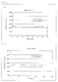
Fig. 4 is a set of graphs each illustrating a working life of each adhesive used in the embodiment of the present invention. -
Fig. 5
Fig. 5 is a view illustrating the execution of an experiment in which a production model is used to evaluate the strength of each adhesive. -
Fig. 6
Fig. 6 is an enlarged photograph of a combining part of a digital thermometer in accordance with the embodiment of the present invention. - The following description will discuss, with reference to the drawings, an embodiment of the present invention.
Fig. 1 is a view schematically illustrating anelectronic part 10 in accordance with the embodiment of the present invention. - As illustrated in
Fig. 1 , theelectronic part 10 is made up of anon-metal part 11 and ametal part 14 covering part of thenon-metal part 11. Astep 11a is provided on a surface of thenon-metal part 11, and thenon-metal part 11 is divided into a lower region (covered region) 11b and an upper region (adjacent region) 11c. Thelower region 11b and themetal part 14 are attached to each other via anadhesive layer 12. This, by design, causes (theupper region 11c of) thenon-metal part 11 and themetal part 14 to share a continuous surface. Note that a cross section of a gap between themetal part 14 and thenon-metal part 11 is in the shape of a letter L. - The
adhesive layer 12 is produced by curing an ultraviolet anaerobic curing adhesive 12a containing a photopolymerization initiator and organic peroxide. Hereinafter, an "ultraviolet anaerobic curing adhesive" refers to an adhesive that is both ultraviolet curing and anaerobic curing. Anaerobic curing refers to curing of an object by having the object come into contact with a metal in an oxygen-free condition. The ultraviolet anaerobic curing adhesive 12a in accordance with the present embodiment contains a photopolymerization initiator. The photopolymerization initiator generates radicals upon reception of ultraviolet light, which radicals trigger an initiation of a polymerization reaction. This ultimately causes an adhesive to be cured. The ultraviolet anaerobic curing adhesive 12a also contains organic peroxide. The organic peroxide (metal catalyst) reacts with a metal (redox reaction), so that radicals are generated. The radicals trigger an initiation of a polymerization reaction. This ultimately causes an adhesive to be cured. - The
electronic part 10 has a hollow 17 enclosed with themetal part 14 and thenon-metal part 11. Asensor 15 for sensing a temperature is provided in the hollow 17, and alead wire 16 for transmitting a signal is connected to thesensor 15. This allows theelectronic part 10 to be suitably used as a component of, for example, a digital thermometer. -
Fig. 2 is a view for describing a method for manufacturing theelectronic part 10. The method for manufacturing theelectronic part 10 includes the steps of (A) forming, between thelower region 11b and themetal part 14, anadhesive layer 12 made of the ultraviolet anaerobic curing adhesive 12a containing both a photopolymerization initiator and organic peroxide and (B) irradiating, with ultraviolet light, a gap between thenon-metal part 11 and themetal part 14. Each of the steps (A) and (B) will be described below in detail. - In the step (A) (refer to the description in the preceding paragraph), the
adhesive layer 12 made of the ultraviolet anaerobic curing adhesive 12a is formed between themetal part 14 and thenon-metal part 11. - Examples of a method for forming the
adhesive layer 12 encompass, but not limited to, a method in which the ultraviolet anaerobic curing adhesive 12a is easily formed by (i) applying or spraying, by use of an adhesive-supplyingmeans 30, the ultraviolet anaerobic curing adhesive 12a to or into thelower region 11b of thenon-metal part 11, respectively (see the left column of (a) ofFig. 2 ) and then (ii) covering the ultraviolet anaerobic curing adhesive 12a with the metal part 14 (see the center column of (a) ofFig. 2 ). - In the step (B) (refer to the description described three paragraphs earlier) after forming the
adhesive layer 12, theadhesive layer 12 is irradiated with ultraviolet light irradiating through a gap between thenon-metal part 11 and themetal part 14. As illustrated in the right column of (a) ofFig. 2 , for example, anultraviolet irradiation apparatus 40 is used to emitultraviolet light 41 through the gap between thestep 11a of thenon-metal part 11 and themetal part 14. - The following description will discuss, in detail with reference to (b) of
Fig. 2 , the mechanism of a curing reaction. (b) ofFig. 2 is a view illustrating the details of, in the step (B), a combining part where thenon-metal part 11 and themetal part 14 are combined together. At the combining part, theadhesive layer 12 is formed between thelower region 11b of thenon-metal part 11 and abottom surface 14b of the metal part 14 (see (b) ofFig. 2 ). - When the
ultraviolet irradiation apparatus 40 is used to emit theultraviolet light 41 through the gap between thestep 11a of thenon-metal part 11 and anend surface 14a of themetal part 14, theultraviolet light 41 thus emitted passes through a pathway indicated by anarrow 41a. This causes a part of theadhesive layer 12, which part is in the vicinity of thestep 11a, to become cured. Then, a chain reaction of radicals generated by the irradiation of the ultraviolet light trigger curing of a part of the ultraviolet anaerobic curing adhesive 12a, which part is in the vicinity of thelower region 11b. - In addition, at the
bottom surface 14b of themetal part 14, radicals are generated by a redox reaction in which the organic peroxide in the adhesive reacts with the metal surface. This causes a part of the ultraviolet anaerobic curing adhesive 12a, which part is in the vicinity of thebottom surface 14b, to be cured. Then, a chain reaction of radicals generated in the vicinity of the metal surface trigger the curing of the ultraviolet anaerobic curing adhesive 12a toward the part in the vicinity of thelower region 11b from thebottom surface 14b. - With such a mechanism of the curing reaction, it is possible to cure on a non-metal-part-11 side of and on a metal-part-14 side of the ultraviolet anaerobic curing adhesive 12a. Note that, in contrast to the conventional technologies, the method in accordance with the present embodiment makes it possible to put the embodiment into practice (i) with excellent workability, (ii) without requiring a high-temperature condition, and (iii) in a short period of time (see Examples described later). In other words, in contrast to electronic parts of the conventional technologies, it is possible, with the electronic part in accordance with the present embodiment, to combine the
non-metal part 11 and themetal part 14 together (i) with excellent workability, (ii) without requiring a high-temperature condition, and (iii) in a short period of time. - Since the
electronic part 10 can be thus assembled in a short period of time, it is possible to expect an improvement in productivity, a reduction in the inventory in a production line, and a simplification of inventory management. Furthermore, since high-temperature heating is not required, it is possible to combine parts together without causing damage to them. This allows a non-metal part to be made of a wide selection of materials. - Examples of the material for the
metal part 14 encompass various materials such as Fe, A1, Cu, Ag, Au, and alloys of such. Especially, Fe, Cu, or an alloy containing at least one of Fe and Cu (e.g. stainless, brass), is preferred because of its fast-curing characteristic and excellent heat conductivity (see Examples described later). - In the present specification, a "non-metal" material refers to any material except for metal, which material has no metallic property. Since the electronic part in accordance with the present embodiment does not require a high-temperature condition in which the
metal part 14 and thenon-metal part 11 are combined together, a wide range of materials can be used as a material for thenon-metal part 11. Examples of the material encompass, but not limited to, at least one material selected from the group consisting of resin, ceramic, glass, and rubber. Examples of the resin encompass PE (polyethylene), PP (polypropylene), PI (polyimide), ABS (acrylonitrile-butadiene-styrene copolymer), PEEK (polyether ether ketone), and LCP (liquid-crystal polymer). Examples of the ceramic encompass Al2O3 and SiC. - The ultraviolet anaerobic curing adhesive 12a is not limited to a specific one, provided that an adhesive is ultraviolet curing and anaerobic curing. Such an adhesive preferably contains a photopolymerization initiator, organic peroxide, and resin.
- Examples of the resin having a curing reactivity encompass an acrylic resin and an epoxy resin. In a case where an acrylic resin or an epoxy resin is used as an ultraviolet curing adhesive, the acrylic resin is to be polymerized with radicals, and the epoxy resin is to be polymerized with cations (or anions). In the present invention, an acrylic resin is preferable from the perspective that radicals, which are generated by irradiation of ultraviolet light or by reactions at a metal surface, are used for a curing reaction of a resin. Examples of the acrylic resin encompass, but not limited to, general acrylate and methacrylate.
- A photopolymerization initiator refers to a substance that generates radicals while being irradiated with ultraviolet light. Examples of the substance encompass, but not limited to: 2-hydroxy-2-methyl-1-phenyl-propan-1-one; 1-hydroxycyclohexyl-phenyl-ketone; 2-benzyl-2-dimethylamino-1-(4-morpholinophenyl)-butanone-1; 2,2-dimethoxy-1,2-diphenylethan-1-one; bis (2,4,6-trimethylbenzoyl)-phenylphosphine oxide; 2-methyl-1 [4-(methylthio) phenyl]-2-morpholinopropan-1-one; 1-[4-(2-hydroxyethoxy)-pheny)-2-hydroxy-2-methyl-1-propan-1-one; 2,4,6-trimethylbenzoyldiphenylphosphine=oxide. It is preferable to use a photopolymerization initiator that has an optimum absorption wavelength with respect to a wavelength of light emitted from a light source to be used for ultraviolet light irradiation.
- Examples of the organic peroxide encompass, but not limited to, hydroperoxide, ketone peroxide, dialkyl peroxide, peroxyester, and diacyl peroxide, all of which have high redox reactivity with metal. Specifically, the examples encompass, but not limited to (i) a hydroperoxide such as: cumene hydroperoxide; t-butyl hydroperoxide; p-menthane hydroperoxide; diisopropylbenzene hydroperoxide; 1,1,3,3-tetramethylbutyl hydroperoxide, (ii) a ketone peroxide such as: methyl ethyl ketone peroxide; cyclohexanone peroxide; acetylacetone peroxide, (iii) a dialkyl peroxide such as dicumyl peroxide; di-t-butyl peroxide; di-t-hexyl peroxide; t-butyl cumyl peroxide, (iv) a peroxyester such as t-butyl peroxypivalate; t-hexyl peroxypivalate, and (v) a diacyl peroxide such as diisobutyryl peroxide and dilauroyl peroxide. Examples
- The following description will discuss, with reference to
Fig. 3 , a preparation of anadhesion evaluation sample 100 that was used in Examples and in Comparative Examples. -
Fig. 3 is a view illustrating each of the steps (1) through (4) in the preparation of theadhesion evaluation sample 100. InFig. 3 , (i) column (a) shows top views each obtained when viewing, from above, theadhesion evaluation sample 100 in the process of being prepared and (ii) column (b) shows side views each obtained when viewing, from the side, theadhesion evaluation sample 100. In addition, Tables 1 and 2 show the respective conditions in each of which theadhesion evaluation sample 100 was prepared. - As illustrated in line (1) of
Fig. 3 , a top surface of anon-metal part 101 used to prepare theadhesion evaluation sample 100 is divided, by astep 101a provided in the vicinity of a center of the top surface, into a lower region (covered region) 101 b and an upper region (adjacent region) 101 c. - As a material for the
non-metal part 101, (i) an ABS (acrylonitrile-butadiene-styrene copolymer) was used in Examples 1 through 4, 8 through 15, and Comparative Examples 1 through 6, (ii) a PEEK (polyether ether ketone) was used in Example 5, (iii) an LCP (liquid-crystal polymer) was used in Example 6, and (iv) a PI (polyimide) was used in Example 7. - Subsequently, a proper amount of an adhesive 102 was dropped to the
lower region 101 b of the non-metal part 101 (see line (2) ofFig. 3 ). - As the adhesive 102, (i) an ultraviolet anaerobic curing adhesive, BU730UF (trade name: ARONIX (registered trademark) manufactured by TOAGOSEI Co., Ltd.), was used in Examples 1 through 12, 14, and 15, (ii) an ultraviolet anaerobic curing adhesive, BU810 (manufactured by TOAGOSEI Co., Ltd.), was used in Example 13, (iii) a thermosetting epoxy adhesive was used in Comparative Example 1, (iv) a moisture curing acrylate adhesive was used in Comparative Example 2, (v) a room-temperature curing silicone adhesive was used in Comparative Example 3, and (vi) an ultraviolet curing adhesive, UVX-5457 (manufactured by TOAGOSEI Co., Ltd.), was used in Comparative Examples 4 through 6.
- Next, as illustrated in line (3) of
Fig. 3 , two thickness gauges 103 were provided on thelower region 101b between which the adhesive 102 is sandwiched. The thickness gauges 103 were spacer members for providing the adhesive 102 in a desired thickness. Thus, pieces of metal (made of SUS), each having a thickness identical with the desired thickness, were used as the thickness gauges 103. Specific thicknesses of the thickness gauges 103 were configured to be (i) 100 µm in Examples 1, 5 through 14, and Comparative Examples 1 through 3, (ii) 50 µm in Example 2, (iii) 200 µm in Example 3, (iv) 400 µm in Example 4, (v) 1,000 µm in Example 15, (vi) 10 µm in Comparative Example 4, (vii) 20 µm in Comparative Example 5, and (viii) 30 µm in Comparative Example 6. - Subsequently, as illustrated in the line (4) of
Fig. 3 , ametal part 104 was laid on thelower region 101b so that each of the thickness gauges 103 is sandwiched between themetal part 104 and thelower region 101b. This caused a layer of anadhesive layer 102 to be formed. Then, the adhesive 102 was cured in a predetermined condition. In Examples 1 through 15, the adhesive 102 was cured through being irradiated with ultraviolet light (UV), and then being left, for a predetermined amount of time, in a thermostatic chamber in which the temperature was held at 60 °C. The predetermined amount of time (curing time) was set to (i) 10 minutes in Examples 1 through 3, 5 through 8, 10, and 13, (ii) 1 hour in Example 4, (iii) 30 minutes in Examples 9, 11, and 12, (iv) 5 minutes in Example 14, and (v) an extended period of time in Example 15. In Comparative Examples 1 through 3, the adhesive 102 was cured through being left, for a predetermined amount of time, in a thermostatic chamber in which respective predetermined temperatures were kept. In Comparative Examples 1 through 3, the adhesive 102 was left in a temperature of 100 °C for 2 hours, in a room temperature for several minutes, and in a room temperature for 24 hours, respectively. Furthermore, in Comparative Examples 4 through 6, the adhesive 102 was cured through being irradiated with ultraviolet light (UV). Note that the irradiation of the ultraviolet light in each Example and Comparative Example was carried out, by use of an ultraviolet irradiation apparatus (manufactured by TAKEDEN Corporation), at an output of 600 mW/cm2 for 2 seconds (equivalent to an ultraviolet light irradiation amount of 1200 mJ/cm2). - After completing the curing of the adhesive 102, the thickness gauges 103 were removed. As illustrated in the line (4) of
Fig. 3 , theadhesion evaluation sample 100, in which themetal part 104 and thenon-metal part 101 were combined together via the cured adhesive 102, was thus prepared. - Subsequently, the adhesion of each adhesion evaluation sample thus prepared was evaluated. The evaluation was made by judging whether or not each adhesive 102 was cured.
- Specifically, whether each adhesive 102 was cured was judged by (i) removing, from the
non-metal part 101, themetal part 104 of theadhesion evaluation sample 100 thus prepared and then (ii) feeling, with a finger, an adhesive remaining on either themetal part 104 or thenon-metal part 101. In so doing, the curing of the adhesive 102 was determined as (a) "NO" in cases where uncured adhesives adhered to the finger or were still tacky and (b) "YES" in cases where cured adhesives were no longer tacky. - A "working life" (also called a "pot life") of an adhesive refers to a period of time between the application of the adhesive and the initiation of an increase in the viscosity of the adhesive in a fixed condition (generally at a temperature of 25 °C (room temperature)). A "working life" serves as an indication pointer of an object's workability.
- The working life of the ultraviolet anaerobic curing adhesives, BU730UF, was measured under both conditions, one in which the temperature was held at 25 °C and the other in which the temperature was held at 40 °C.
Fig. 4 illustrates the results. - (a) of
Fig. 4 illustrates how a viscosity of the ultraviolet anaerobic curing adhesive, BU730UF, changes over time at a temperature of 25 °C. In this case, a noticeable increase in the viscosity was not observed for at least two (2) months. This made it clear that the working life of the adhesive at a temperature of 25 °C is at least two (2) months. On the other hand, (b) ofFig. 4 illustrates how a viscosity of the ultraviolet anaerobic curing adhesive, BU730UF, changes over time at a temperature of 40 °C. As shown in (b) ofFig. 4 , a noticeable increase in the viscosity was not observed for at least 200 hours. This indicates that the working life of the adhesive at a temperature of 40 °C is at least 200 hours. Each working life of the other adhesives used in Examples and Comparative Examples was likewise measured. - A
production model 200 of a digital thermometer was prepared with the use of an adhesive (ultraviolet anaerobic curing adhesive, BU730UF (trade name: ARONIX (registered trademark) manufactured by TOAGOSEI Co., Ltd.) identical to the one used in Example 1. The adhesive was applied to a tip of a resin main body (non-metal part) 201, and a stainless cap (metal part) 204 was then fitted in the tip. The length, at a combining surface, between the resinmain body 201 and thestainless cap 204 was set to 250 µm. Subsequently, an ultraviolet irradiation apparatus was used to irradiate theproduction model 200 with ultraviolet light at an output of 600 mW/cm2 for 2 seconds (equivalent to an ultraviolet light irradiation amount of 1200 mJ/cm2). Theproduction model 200 was then left, for 10 minutes, in a thermostatic chamber in which the temperature was held at 60 °C. - Then, the adhesion strength of the
production model 200 thus prepared was measured.Fig. 5 illustrates how the adhesion strength of theproduction model 200 was measured. An adhesionstrength measuring device 400 includes (i) afixing section 401 for fixing the resinmain body 201 of theproduction model 200 and (ii) afixing section 402 for fixing thestainless cap 204 of theproduction model 200. Aload generating section 403 was then used to apply load in such a direction that separates the fixingsection 401 from the fixingsection 402. The result (a) showed that an adhesive layer provided between the resinmain body 201 and thestainless cap 204 was completely cured and therefore (b) demonstrated that the adhesive had adhesion strength of not less than 100 N. - The adhesion strength of the
production model 200 was likewise measured and evaluated under each of the conditions of Examples 2 through 15 and Comparative Examples 1 through 6. - The results are shown in Tables 1 and 2 below. In the "Cured (Adhering)" row, "YES" and "NO" are shown as "o" and "x" respectively. In the "Curing Condition", "Curing Time", and "Working Life" rows, "o", "Δ", or "×" was added to indicate that the data of the respective sections was favorable, acceptable, or unfavorable, respectively. In the "Adhesion Strength" row, "x", "Δ", or "o" was put down to indicate that the adhesion strength was (i) less than 20 N, (ii) in the range of 20 N to 80 N, or (iii) more than 80 N, respectively.
Table 1 Example 1 Example 2 Example 3 Example 4 Example 5 Example 6 Example 7 Example 8 Example 9 Example 10 Example 11 Metal Part SUS SUS SUS SUS SUS SUS SUS Fe Al Cu Ag Non-Metal Part ABS ABS ABS ABS PEEK LCP PI ABS ABS ABS ABS Adhesive BU730UF UV Anaerobic BU730UF UV Anaerobic BU730UF UV Anaerobic BU730UF UV Anaerobic BU730UF UV Anaerobic BU730UF UV Anaerobic BU730UF UV Anaerobic BU730UF UV Anaerobic BU730UF UV Anaerobic BU730UF UV Anaerobic BU730UF UV Anaerobic A. T. 100 µ m 50 µ m 200 µ m 400 µ m 100 µm 100 µ m 100 µ m 100 µ m 100 µ m 100 µ m 100 µm Curing Condition UV, 60°C V, 60 °C UV, 6 0°C UV, 60°C UV, 60°C UV, 60°C. UV, 6 0°C UV, 60°C UV, 60°C. UV, 60 °C UV, 60°C ○ ○ ○ ○ ○ ○ ○ ○ ○ ○ ○ Curing Time 10 Min. 10 Min 10 Min 1 Hr. 10 Min. 10 Min. 10 Min. 10 Min 30 Min. 10 Min 30 Min. ○ ○ ○ Δ ○ ○ ○ ○ Δ ○ Δ Adhering ○ ○ ○ ○ ○ ○ ○ ○ ○ ○ ○ A S ○ ○ ○ ○ ○ ○ ○ ○ ○ ○ ○ Working Life Several Mon. Several Mon. Several Mon. Several Mon Several Mon Several Mon Several Mon Several Mon. Several Mon. Several Mon. Several Mon. ○ ○ ○ ○ ○ ○ ○ ○ ○ ○ ○ * List of Abbreviations and Explanations
A. T. = Adhesive Thickness; A. S. = Adhesion Strength;
Min. = Minutes; Hr. = hours; Mon. = monthsTable 2 Example 12 Example 13 Example 14 Example 15 C. E. 1 C. E. 2 C. E. 3 C. E. 4 C. E. 5 C. E. 6 Metal Part Au SUS SUS SUS SUS SUS SUS SUS SUS SUS n-Metal Part ABS ABS ABS ABS ABS ABS ABS ABS ABS ABS Adhesive BU730UF UV Anaerobic BU810 UV Anaerobic BU730UF UV Anaerobic BU730UF UV Anaerobic Thermosetting Epoxy Moisture Curing Acrylate R. T. Curing Silicon UVX-5457 UV UVX-5457 UV UVX-6457 UV A. T. 100 µ m 100 µ m 100 µ m 100 µ m 100 µ m 100 µ m 100 µ m 10 µ m 20 µ m 30 µm Curing Condition UV, 60°C UV, 60°C V, 60°C UV, 60°C 100°C R.T. R. T. UV UV UV Δ ○ ○ ○ ○ ○ ○ ○ ○ Curing Time 30 Min 10 Min. 5 Min. - 2 Hr. Several Min. 24 Hr. Several Sec. Several Sec. Several Sec. Δ ○ ○ Δ ○ Δ ○ ○ ○ Adhering ○ ○ × × ○ ○ ○ ○ × × A. S. ○ ○ Δ × ○ ○ ○ ○ × × Working Life Several Mon. Several Mon. Several Mon. Several Mon. 5 Hr. Several Mien. 24 Hr. Several Mon. Several Mon. Several Mon. ○ ○ ○ ○ Δ X Δ ○ ○ ○ * List of Abbreviations and Explanations
C. E. = Comparative Example; R. T. = Room Temperature; A. T. = Adhesive Thickness; A. S. = Adhesion Strength; Sec. = Seconds; Min. = Minutes; Hr. = hours; Mon. = months - As shown in each Example, the use of the ultraviolet anaerobic curing adhesive made it possible to combine the metal part and the non-metal part together (i) at relatively low temperature (e.g. 60 °C), (ii) in a short period of time (for example, 10 minutes), and (iii) with excellent workability (working life: several months). Additionally, as shown in Example 4, the metal part and the non-metal part were successfully combined together even in a case where the adhesive was thick (400 µm).
- As shown in Comparative Example 1, on the other hand, a curing procedure was necessary at high temperature (100 °C) and for an extended period of time (2 hours) in a case where a thermosetting epoxy adhesive was used. On top of that, the working life of the thermosetting epoxy adhesive was relatively short (5 hours). This suggests that, in a case where a thermosetting epoxy adhesive is used, (i) parts involved need to be heat resistant, (ii) an assembling efficiency is substandard, and (iii) the workability of a device is unsatisfactory.
- In a case where a moisture curing acrylate adhesive was used (see Comparative Example 2), the working life of the adhesive was extremely short (several minutes) despite the fact that a metal part and a non-metal part were combined together in a short period of time. This suggests unsatisfactory workability of a device in a case where a moisture curing acrylate adhesive is used. It was also problematic that ingredients of the adhesive caused a degradation of surfaces of a resin (ABS).
- In a case where a room-temperature silicone adhesive was used (see Comparative Example 3), it required a significantly long time (24 hours) to cure the adhesive. This suggests a significantly substandard assembling efficiency in such a case.
- In cases where (i) ultraviolet curing adhesives were used and (ii) the adhesives were thick (20 µm or more), the adhesion of the adhesives was insufficient (see Comparative Examples 4 through 6).
- It was thus revealed that the present invention makes it possible to combine together a metal part and a non-metal part more suitably than the conventional technologies.
- It was also revealed, by comparing the results of Example 1 and 14, that the use of the ultraviolet curing adhesive makes it possible to suitably cure, within 10 minutes, an adhesive having a thickness of 100 µm.
- It was also revealed, by comparing the results of Examples 1 through 4 and Example 15, that the use of the ultraviolet curing adhesive makes it possible to cure an adhesive having a thickness of 400 µm.
- It was also revealed, by comparing the results of Examples 1 and 5 through 7, that examples of a material for the non-metal parts to be combined encompass a variety of non-metal materials such as an ABS (acrylonitrile-butadiene-styrene copolymer), a PEEK (polyether ether ketone), an LCP (liquid-crystal polymer), and a PI (polyimide).
- It was also revealed, by comparing the results of Examples 1 and 8 through 12, that examples of a material for the metal parts to be combined encompass a variety of metals such as SUS, Fe, A1, Cu, AG, and Au. Furthermore, it was revealed that a curing time is especially short in a case where a metal part is made of Fe or Cu.
-
Fig. 6 is an enlarged photograph of a combining part at which the resinmain body 201 and thestainless cap 204 are combined together in theproduction model 200. A gap L201-204, in a vertical direction ofFig. 6 , between the resinmain body 201 and the stainless cap 204 (precisely, between a step 201a of the resinmain body 201 and an end surface 204a of the stainless cap 204) was in the range of 2 µm to 20 µm. - It is preferable to arrange the electronic part in accordance with the present invention such that an adhesive layer has a thickness of more than 0 µm and not more than 400 µm.
- The electronic part, in a case where its thickness falls in the range above, can be efficiently assembled.
- The electronic part in accordance with the present invention (i) can be arranged such that a step is provided between a covered region and an adjacent region which is adjacent, on a surface of a non-metal part, to the covered region, the step being provided so that the adjacent region is elevated higher than the covered region and (ii) is preferably arranged such that the non-metal part and a metal part share a continuous surface.
- According to the electronic part in accordance with the present invention, (i) a part of an adhesive, which part is on a metal-part side, is cured by an aerobic curing effect and (ii) a part of the adhesive, which part is on a non-metal-part side, is cured by an ultraviolet curing effect produced by reflection of ultraviolet light entering from a gap between the non-metal part and the metal part. Therefore, even in a case where such a step as one described above is provided on the surface of the non-metal part so that the gap between the non-metal part and the metal part has an L-shaped cross section, the non-metal part and the metal part can be successfully combined together. With the configuration, it is also possible to suitably provide an electronic part made up of a non-metal part and a metal part which share a continuous surface.
- It is preferable to arrange the electronic part in accordance with the present invention such that the metal part is made of iron, copper, or an alloy containing at least one of iron and copper.
- With the configuration, it is possible to cure an ultraviolet anaerobic curing adhesive in a short period of time. Therefore, the non-metal part and the metal part can be combined together in even a shorter period of time.
- It is preferable to arrange the electronic part in accordance with the present invention such that the non-metal part is made of at least one material selected from a group consisting of resin, ceramic, glass, and rubber.
- At least one material selected from a group consisting of resin, ceramic, glass, and rubber, can be suitably used as a material for the non-metal part of the electronic part in accordance with the present invention.
- The electronic part in accordance with the present invention can further include: a sensor provided in a hollow enclosed with the metal part and the non-metal part. The sensor can be a sensor for sensing a temperature.
- With the configuration, it is possible to provide an electronic part which is, for example, to be mounted on a digital thermometer.
- Electronic equipment and electronic devices, such as digital thermometers each including the electronic part in accordance with the present invention, also fall within the scope of the present invention.
- It is preferable to arrange a method in accordance with the present invention for manufacturing an electronic part such that an adhesive layer has a thickness of more than 0 µm and no more than 400 µm.
- With the configuration, it is possible to suitably carry out curing of the adhesive layer.
- It is preferable to arrange the method such that: a step is provided between a covered region and an adjacent region which is adjacent, on a surface of a non-metal part, to the covered region, the step being provided so that the adjacent region is elevated higher than the covered region; and, in the step of irradiating, with ultraviolet light, a gap between the non-metal part and a metal part, a gap between the step and the metal part is irradiated with the ultraviolet light.
- According to the configuration, (i) a part of an adhesive, which part is on a metal-part side, is cured by an aerobic curing effect and (ii) a part of the adhesive, which part is on a non-metal-part side, is cured by use of a sequentially occurring curing reaction of radicals generated by ultraviolet light entering from a gap between the step and the metal part. Therefore, even in a case where such a step as one described above is provided on the surface of the non-metal part so that the gap between the non-metal part and the metal part has an L-shaped cross section, the non-metal part and the metal part can be successfully combined together.
- It is preferable to arrange the method such that the metal part is made of iron, copper, or an alloy containing at least one of iron and copper.
- With the configuration, the adhesive layer can be cured in even a shorter period of time.
- The embodiment and the concrete examples, which have been discussed in the detailed description, are illustrative only, which should not be narrowly interpreted within the limits of such embodiment and concrete examples, but are rather meant to be applied in any variations within the spirit of the present invention, provided that such variations do not exceed the scope of the patent claims set forth below.
- The present invention can be used for (i) manufacturing an electronic part made up of a metal part and a non-metal part and (ii) manufacturing various electrical equipment and electronic devices, including medical equipment such as a digital thermometer.
-
- 10
- Electronic part
- 11
- Non-metal part
- 11a
- Step
- 11b
- Lower region (covered region)
- 11c
- Upper region (adjacent region)
- 12
- Adhesive layer
- 12a
- Ultraviolet anaerobic curing adhesive
- 14
- Metal part
- 14a
- End surface
- 14b
- Bottom surface
- 15
- Temperature-sensing element
- 16
- Lead wire
- 30
- Adhesive-supplying means
- 40
- Ultraviolet irradiation apparatus
- 41
- Ultraviolet light
- 41a
- Ultraviolet light pathway
- 100
- Testing-evaluating sample
- 101
- Non-metal part
- 101a
- Step
- 101b
- Lower region (covered region)
- 101c
- Upper region (adjacent region)
- 102
- Adhesive
- 103
- Thickness gauge
- 104
- Metal part
- 200
- Production model (digital thermometer)
- 201
- Resin main body (non-metal part)
- 204
- Stainless cap (metal part)
- 400
- Adhesion strength measuring device
- 401
- Fixing section
- 402
- Fixing section
- 403
- Load generating section
Claims (13)
- An electronic part comprising:a non-metal part; anda metal part covering a covered region provided on a surface of the non-metal part,the covered region and the metal part being combined together via an adhesive layer provided by curing an ultraviolet anaerobic curing adhesive containing a photopolymerization initiator and organic peroxide.
- The electronic part as set forth in claim 1, wherein the adhesive layer has a thickness of more than 0 µm and not more than 400 µm.
- The electronic part as set forth in claim 1, wherein a step is provided between the covered region and an adjacent region which is adjacent, on the surface of the non-metal part, to the covered region, the step being provided so that the adjacent region is elevated higher than the covered region.
- The electronic part as set forth in claim 3, wherein the non-metal part and the metal part share a continuous surface.
- The electronic part as set forth in claim 1, wherein the metal part is made of iron, copper, or an alloy containing at least one of iron and copper.
- The electronic part as set forth in claim 1, wherein the non-metal part is made of at least one material selected from the group consisting of resin, ceramic, glass, and rubber.
- An electronic part as set forth in claim 1, further comprising:a sensor provided in a hollow enclosed with the metal part and the non-metal part.
- The electronic part as set forth in claim 7, wherein the sensor is a sensor for sensing a temperature.
- A digital thermometer comprising the electronic part as set forth in claim 8.
- A method for manufacturing an electronic part,
said electronic part, comprising:a non-metal part; anda metal part covering a covered region provided on a surface of the non-metal part,said method, comprising the steps of:(i) forming, between the covered region and the metal part, an adhesive layer by use of an ultraviolet anaerobic curing adhesive containing a photopolymerization initiator and organic peroxide; and(ii) irradiating, with ultraviolet light, a gap between the non-metal part and the metal part. - The method as set forth in claim 10, wherein the adhesive layer has a thickness of more than 0 µm and not more than 400 µm.
- The method as set forth in claim 10, wherein:a step is provided between the covered region and an adjacent region which is adjacent, on the surface of the non-metal part, to the covered region, the step being provided so that the adjacent region is elevated higher than the covered region; andin the step (ii), a gap between the step and the metal part is irradiated with the ultraviolet light.
- The method as set forth in claim 10, wherein the metal part is made of iron, copper, or an alloy containing at least one of iron and copper.
Applications Claiming Priority (2)
| Application Number | Priority Date | Filing Date | Title |
|---|---|---|---|
| JP2010053455A JP4816800B2 (en) | 2010-03-10 | 2010-03-10 | Electronic component, method for manufacturing electronic component, and electronic thermometer |
| PCT/JP2011/053743 WO2011111512A1 (en) | 2010-03-10 | 2011-02-21 | Electronic part, method of manufacture for electronic part and digital thermometer |
Publications (2)
| Publication Number | Publication Date |
|---|---|
| EP2546055A1 true EP2546055A1 (en) | 2013-01-16 |
| EP2546055A4 EP2546055A4 (en) | 2013-05-22 |
Family
ID=44563328
Family Applications (1)
| Application Number | Title | Priority Date | Filing Date |
|---|---|---|---|
| EP11753174.9A Withdrawn EP2546055A4 (en) | 2010-03-10 | 2011-02-21 | Electronic part, method of manufacture for electronic part and digital thermometer |
Country Status (5)
| Country | Link |
|---|---|
| US (1) | US20130051429A1 (en) |
| EP (1) | EP2546055A4 (en) |
| JP (1) | JP4816800B2 (en) |
| CN (1) | CN102791477A (en) |
| WO (1) | WO2011111512A1 (en) |
Citations (2)
| Publication number | Priority date | Publication date | Assignee | Title |
|---|---|---|---|---|
| US6676795B1 (en) * | 2001-07-30 | 2004-01-13 | Henkel Loctite Corporation | Bonded assembly and method for preparing same |
| US20090168838A1 (en) * | 2007-12-31 | 2009-07-02 | Tyco Healthcare Group Lp | Thermometer having molded probe component |
Family Cites Families (17)
| Publication number | Priority date | Publication date | Assignee | Title |
|---|---|---|---|---|
| JPS6023794B2 (en) * | 1979-02-22 | 1985-06-10 | 東亞合成株式会社 | Anaerobic curable composition with photocurability |
| JPS57119970A (en) * | 1981-01-16 | 1982-07-26 | Matsushita Electric Ind Co Ltd | Bonding rotor to shaft |
| US4511911A (en) | 1981-07-22 | 1985-04-16 | International Business Machines Corporation | Dense dynamic memory cell structure and process |
| JPS6023794A (en) | 1983-07-18 | 1985-02-06 | Matsushita Electric Ind Co Ltd | Heat exchange device |
| US4533446A (en) * | 1983-07-20 | 1985-08-06 | Loctite (Ireland) Ltd. | Radiation-activatable anaerobic adhesive composition |
| JPS60229974A (en) * | 1984-04-27 | 1985-11-15 | Toshiba Corp | Bonding of plates |
| JPH03106918A (en) * | 1989-09-19 | 1991-05-07 | Nitto Denko Corp | Ultraviolet-curable resin composition |
| JPH03118432A (en) | 1989-09-29 | 1991-05-21 | Terumo Corp | Electronic clinical thermometer and manufacture thereof |
| JPH06225495A (en) | 1993-01-25 | 1994-08-12 | Fuji Electric Co Ltd | Fabrication of spindle motor |
| JP2000111414A (en) * | 1998-10-09 | 2000-04-21 | Hyakuryaku Kigyo Kofun Yugenkoshi | Clinical thermometer |
| AU2001229082A1 (en) * | 2000-12-15 | 2002-06-24 | Loctite Corporation | Adhesives for dvd bonding |
| JP3995490B2 (en) * | 2002-02-05 | 2007-10-24 | ミネベア株式会社 | Pivot assembly and manufacturing method thereof |
| JP4593222B2 (en) * | 2004-09-29 | 2010-12-08 | シチズンホールディングス株式会社 | Manufacturing method of electronic thermometer |
| JP4479614B2 (en) | 2005-07-12 | 2010-06-09 | パナソニック株式会社 | Optical pickup device |
| US20070058691A1 (en) * | 2005-09-14 | 2007-03-15 | Oriental System Technology Inc. | Electronic thermometer |
| WO2007120630A2 (en) * | 2006-04-10 | 2007-10-25 | Abm Associates Llc | Activated anaerobic adhesive and use thereof |
| CN2909201Y (en) * | 2006-04-25 | 2007-06-06 | 捷威科技股份有限公司 | Thermometer |
-
2010
- 2010-03-10 JP JP2010053455A patent/JP4816800B2/en active Active
-
2011
- 2011-02-21 CN CN2011800128565A patent/CN102791477A/en active Pending
- 2011-02-21 EP EP11753174.9A patent/EP2546055A4/en not_active Withdrawn
- 2011-02-21 US US13/583,109 patent/US20130051429A1/en not_active Abandoned
- 2011-02-21 WO PCT/JP2011/053743 patent/WO2011111512A1/en active Application Filing
Patent Citations (2)
| Publication number | Priority date | Publication date | Assignee | Title |
|---|---|---|---|---|
| US6676795B1 (en) * | 2001-07-30 | 2004-01-13 | Henkel Loctite Corporation | Bonded assembly and method for preparing same |
| US20090168838A1 (en) * | 2007-12-31 | 2009-07-02 | Tyco Healthcare Group Lp | Thermometer having molded probe component |
Non-Patent Citations (2)
| Title |
|---|
| DATABASE WPI Week 199124 Thomson Scientific, London, GB; AN 1991-175162 XP002695352, -& JP 3 106918 A (NITTO DENKO CORP) 7 May 1991 (1991-05-07) * |
| See also references of WO2011111512A1 * |
Also Published As
| Publication number | Publication date |
|---|---|
| JP2011185859A (en) | 2011-09-22 |
| JP4816800B2 (en) | 2011-11-16 |
| EP2546055A4 (en) | 2013-05-22 |
| US20130051429A1 (en) | 2013-02-28 |
| WO2011111512A1 (en) | 2011-09-15 |
| CN102791477A (en) | 2012-11-21 |
Similar Documents
| Publication | Publication Date | Title |
|---|---|---|
| Zhao et al. | Kirigami enhances film adhesion | |
| KR102331226B1 (en) | Adhesive tape for dicing and method for manufacturing semiconductor chip | |
| JP6098289B2 (en) | Thermally conductive sheet | |
| WO2012067205A1 (en) | Method for processing light-transmitting rigid substrate laminate and method for manufacturing plate shaped product | |
| US20150166855A1 (en) | Adhesive composition containing uv curable rubber, and protective film using same | |
| KR20130095654A (en) | Method for separating bonded bodies using excimer light irradiation | |
| JP2018009102A (en) | Photocurable resin composition for imprint molding | |
| WO2008078828A1 (en) | Display substrate for embedding pixel control element | |
| JP5270914B2 (en) | Resin composition and cured product and sheet using the same | |
| EP2546055A1 (en) | Electronic part, method of manufacture for electronic part and digital thermometer | |
| JP2011057956A (en) | Adhesive sheet for plating | |
| JP2012188617A (en) | Anisotropic conductive adhesion sheet, composition for forming the same, conduction connection structure of electronic component, and method of manufacturing anisotropic conductive adhesion sheet | |
| KR102257952B1 (en) | Curable polyorganosiloxane composition and use thereof | |
| US20170077055A1 (en) | Anisotropic conductive film and production method of the same | |
| EP3689597A1 (en) | Structure, wiring board, base material for wiring boards, copper-clad laminate, and method for producing structure | |
| KR102320282B1 (en) | Electropole disk and method for manufacturing electric pole mold using the electric pole disk | |
| JP2001261722A (en) | Curable composition for thermal conductive sheet, semicured thermal conductive sheet and method for producing the same | |
| JP2007273768A (en) | Adhesive sheet and its using method | |
| US10849236B2 (en) | Anisotropic conductive film and production method of the same | |
| JP2017080970A (en) | Glass laminate, substrate for electronic device, and electronic device | |
| KR101364438B1 (en) | Manufacturing method of semiconductor device using a energy ray -responsive heat-resistant adhesive sheet | |
| CN113261107A (en) | Manufacturing method of flexible electronic device and flexible electronic device | |
| JP7108505B2 (en) | Machinability-enhancing film, laminate, and method of using machinability-enhancing film | |
| KR101218144B1 (en) | Manufacturing method of semiconductor device using a heat-resistant adhesive sheet | |
| JP2016042541A (en) | Method for manufacturing connection structure, and anisotropic conducting adhesive film |
Legal Events
| Date | Code | Title | Description |
|---|---|---|---|
| PUAI | Public reference made under article 153(3) epc to a published international application that has entered the european phase |
Free format text: ORIGINAL CODE: 0009012 |
|
| 17P | Request for examination filed |
Effective date: 20120928 |
|
| AK | Designated contracting states |
Kind code of ref document: A1 Designated state(s): AL AT BE BG CH CY CZ DE DK EE ES FI FR GB GR HR HU IE IS IT LI LT LU LV MC MK MT NL NO PL PT RO RS SE SI SK SM TR |
|
| A4 | Supplementary search report drawn up and despatched |
Effective date: 20130419 |
|
| RIC1 | Information provided on ipc code assigned before grant |
Ipc: G01K 7/00 20060101ALI20130412BHEP Ipc: G01K 1/08 20060101ALI20130412BHEP Ipc: B32B 15/08 20060101AFI20130412BHEP Ipc: C09J 5/10 20060101ALI20130412BHEP |
|
| DAX | Request for extension of the european patent (deleted) | ||
| 17Q | First examination report despatched |
Effective date: 20160616 |
|
| STAA | Information on the status of an ep patent application or granted ep patent |
Free format text: STATUS: EXAMINATION IS IN PROGRESS |
|
| STAA | Information on the status of an ep patent application or granted ep patent |
Free format text: STATUS: THE APPLICATION IS DEEMED TO BE WITHDRAWN |
|
| 18D | Application deemed to be withdrawn |
Effective date: 20161027 |