EP2540366A2 - Fuel deoxygenation using surface-modified porous membranes - Google Patents
Fuel deoxygenation using surface-modified porous membranes Download PDFInfo
- Publication number
- EP2540366A2 EP2540366A2 EP12174443A EP12174443A EP2540366A2 EP 2540366 A2 EP2540366 A2 EP 2540366A2 EP 12174443 A EP12174443 A EP 12174443A EP 12174443 A EP12174443 A EP 12174443A EP 2540366 A2 EP2540366 A2 EP 2540366A2
- Authority
- EP
- European Patent Office
- Prior art keywords
- porous membrane
- fuel
- membrane
- pores
- oxygen
- Prior art date
- Legal status (The legal status is an assumption and is not a legal conclusion. Google has not performed a legal analysis and makes no representation as to the accuracy of the status listed.)
- Withdrawn
Links
- 239000012528 membrane Substances 0.000 title claims abstract description 221
- 239000000446 fuel Substances 0.000 title claims abstract description 103
- 238000006392 deoxygenation reaction Methods 0.000 title claims abstract description 12
- QVGXLLKOCUKJST-UHFFFAOYSA-N atomic oxygen Chemical compound [O] QVGXLLKOCUKJST-UHFFFAOYSA-N 0.000 claims abstract description 101
- 239000001301 oxygen Substances 0.000 claims abstract description 101
- 229910052760 oxygen Inorganic materials 0.000 claims abstract description 101
- 239000011148 porous material Substances 0.000 claims abstract description 81
- 238000000034 method Methods 0.000 claims abstract description 30
- 239000003795 chemical substances by application Substances 0.000 claims abstract description 14
- 238000011282 treatment Methods 0.000 claims abstract description 14
- 238000000151 deposition Methods 0.000 claims abstract description 9
- 239000002904 solvent Substances 0.000 claims abstract description 6
- 238000010438 heat treatment Methods 0.000 claims abstract description 3
- 150000001875 compounds Chemical class 0.000 claims description 10
- CXGONMQFMIYUJR-UHFFFAOYSA-N perfluorododecanoic acid Chemical group OC(=O)C(F)(F)C(F)(F)C(F)(F)C(F)(F)C(F)(F)C(F)(F)C(F)(F)C(F)(F)C(F)(F)C(F)(F)C(F)(F)F CXGONMQFMIYUJR-UHFFFAOYSA-N 0.000 claims description 6
- 150000001735 carboxylic acids Chemical class 0.000 claims description 5
- 230000008021 deposition Effects 0.000 claims description 5
- 239000010410 layer Substances 0.000 description 37
- 238000004939 coking Methods 0.000 description 5
- IJGRMHOSHXDMSA-UHFFFAOYSA-N Atomic nitrogen Chemical compound N#N IJGRMHOSHXDMSA-UHFFFAOYSA-N 0.000 description 4
- 238000006701 autoxidation reaction Methods 0.000 description 4
- 238000010586 diagram Methods 0.000 description 4
- 238000012986 modification Methods 0.000 description 4
- 230000004048 modification Effects 0.000 description 4
- 230000006641 stabilisation Effects 0.000 description 4
- 238000011105 stabilization Methods 0.000 description 4
- 230000015572 biosynthetic process Effects 0.000 description 3
- 239000007789 gas Substances 0.000 description 3
- 125000002887 hydroxy group Chemical group [H]O* 0.000 description 3
- 239000007788 liquid Substances 0.000 description 3
- 239000000463 material Substances 0.000 description 3
- 239000000243 solution Substances 0.000 description 3
- QAOWNCQODCNURD-UHFFFAOYSA-N Sulfuric acid Chemical compound OS(O)(=O)=O QAOWNCQODCNURD-UHFFFAOYSA-N 0.000 description 2
- 238000013459 approach Methods 0.000 description 2
- 239000000571 coke Substances 0.000 description 2
- 230000003635 deoxygenating effect Effects 0.000 description 2
- 238000001035 drying Methods 0.000 description 2
- -1 fluoroalkyl silanes Chemical class 0.000 description 2
- 229930195733 hydrocarbon Natural products 0.000 description 2
- 150000002430 hydrocarbons Chemical class 0.000 description 2
- 238000002347 injection Methods 0.000 description 2
- 239000007924 injection Substances 0.000 description 2
- 229910052757 nitrogen Inorganic materials 0.000 description 2
- 238000009832 plasma treatment Methods 0.000 description 2
- 229920001296 polysiloxane Polymers 0.000 description 2
- BPCXHCSZMTWUBW-UHFFFAOYSA-N triethoxy(1,1,2,2,3,3,4,4,5,5,8,8,8-tridecafluorooctyl)silane Chemical group CCO[Si](OCC)(OCC)C(F)(F)C(F)(F)C(F)(F)C(F)(F)C(F)(F)CCC(F)(F)F BPCXHCSZMTWUBW-UHFFFAOYSA-N 0.000 description 2
- 239000004215 Carbon black (E152) Substances 0.000 description 1
- 229910000323 aluminium silicate Inorganic materials 0.000 description 1
- 239000006227 byproduct Substances 0.000 description 1
- 238000005266 casting Methods 0.000 description 1
- 239000003054 catalyst Substances 0.000 description 1
- 229910010293 ceramic material Inorganic materials 0.000 description 1
- 238000006243 chemical reaction Methods 0.000 description 1
- 238000002485 combustion reaction Methods 0.000 description 1
- 238000004891 communication Methods 0.000 description 1
- 238000007906 compression Methods 0.000 description 1
- 239000000470 constituent Substances 0.000 description 1
- 239000002826 coolant Substances 0.000 description 1
- 238000001816 cooling Methods 0.000 description 1
- 238000005516 engineering process Methods 0.000 description 1
- 238000005886 esterification reaction Methods 0.000 description 1
- 150000002148 esters Chemical class 0.000 description 1
- 230000001747 exhibiting effect Effects 0.000 description 1
- 239000000835 fiber Substances 0.000 description 1
- 125000000524 functional group Chemical group 0.000 description 1
- 229910010272 inorganic material Inorganic materials 0.000 description 1
- 239000011147 inorganic material Substances 0.000 description 1
- 230000007774 longterm Effects 0.000 description 1
- 238000012423 maintenance Methods 0.000 description 1
- 239000002184 metal Substances 0.000 description 1
- 229910044991 metal oxide Inorganic materials 0.000 description 1
- 150000004706 metal oxides Chemical class 0.000 description 1
- 125000000896 monocarboxylic acid group Chemical group 0.000 description 1
- 229920000620 organic polymer Polymers 0.000 description 1
- 238000007254 oxidation reaction Methods 0.000 description 1
- 239000012466 permeate Substances 0.000 description 1
- 229920000642 polymer Polymers 0.000 description 1
- 239000002861 polymer material Substances 0.000 description 1
- 239000002243 precursor Substances 0.000 description 1
- 239000000047 product Substances 0.000 description 1
- 150000003254 radicals Chemical class 0.000 description 1
- 238000005057 refrigeration Methods 0.000 description 1
- 229920006395 saturated elastomer Polymers 0.000 description 1
- 229910000077 silane Inorganic materials 0.000 description 1
- 239000002356 single layer Substances 0.000 description 1
- 150000003384 small molecules Chemical class 0.000 description 1
- 239000000126 substance Substances 0.000 description 1
- 239000004753 textile Substances 0.000 description 1
Images

Classifications
-
- B—PERFORMING OPERATIONS; TRANSPORTING
- B01—PHYSICAL OR CHEMICAL PROCESSES OR APPARATUS IN GENERAL
- B01D—SEPARATION
- B01D61/00—Processes of separation using semi-permeable membranes, e.g. dialysis, osmosis or ultrafiltration; Apparatus, accessories or auxiliary operations specially adapted therefor
- B01D61/36—Pervaporation; Membrane distillation; Liquid permeation
- B01D61/362—Pervaporation
-
- B—PERFORMING OPERATIONS; TRANSPORTING
- B01—PHYSICAL OR CHEMICAL PROCESSES OR APPARATUS IN GENERAL
- B01D—SEPARATION
- B01D19/00—Degasification of liquids
- B01D19/0031—Degasification of liquids by filtration
-
- B—PERFORMING OPERATIONS; TRANSPORTING
- B01—PHYSICAL OR CHEMICAL PROCESSES OR APPARATUS IN GENERAL
- B01D—SEPARATION
- B01D67/00—Processes specially adapted for manufacturing semi-permeable membranes for separation processes or apparatus
- B01D67/0002—Organic membrane manufacture
- B01D67/0023—Organic membrane manufacture by inducing porosity into non porous precursor membranes
- B01D67/0025—Organic membrane manufacture by inducing porosity into non porous precursor membranes by mechanical treatment, e.g. pore-stretching
- B01D67/0027—Organic membrane manufacture by inducing porosity into non porous precursor membranes by mechanical treatment, e.g. pore-stretching by stretching
-
- B—PERFORMING OPERATIONS; TRANSPORTING
- B01—PHYSICAL OR CHEMICAL PROCESSES OR APPARATUS IN GENERAL
- B01D—SEPARATION
- B01D67/00—Processes specially adapted for manufacturing semi-permeable membranes for separation processes or apparatus
- B01D67/0002—Organic membrane manufacture
- B01D67/0023—Organic membrane manufacture by inducing porosity into non porous precursor membranes
- B01D67/0032—Organic membrane manufacture by inducing porosity into non porous precursor membranes by elimination of segments of the precursor, e.g. nucleation-track membranes, lithography or laser methods
- B01D67/0034—Organic membrane manufacture by inducing porosity into non porous precursor membranes by elimination of segments of the precursor, e.g. nucleation-track membranes, lithography or laser methods by micromachining techniques, e.g. using masking and etching steps, photolithography
-
- B—PERFORMING OPERATIONS; TRANSPORTING
- B01—PHYSICAL OR CHEMICAL PROCESSES OR APPARATUS IN GENERAL
- B01D—SEPARATION
- B01D67/00—Processes specially adapted for manufacturing semi-permeable membranes for separation processes or apparatus
- B01D67/0081—After-treatment of organic or inorganic membranes
- B01D67/0088—Physical treatment with compounds, e.g. swelling, coating or impregnation
-
- B—PERFORMING OPERATIONS; TRANSPORTING
- B01—PHYSICAL OR CHEMICAL PROCESSES OR APPARATUS IN GENERAL
- B01D—SEPARATION
- B01D69/00—Semi-permeable membranes for separation processes or apparatus characterised by their form, structure or properties; Manufacturing processes specially adapted therefor
- B01D69/12—Composite membranes; Ultra-thin membranes
-
- B—PERFORMING OPERATIONS; TRANSPORTING
- B01—PHYSICAL OR CHEMICAL PROCESSES OR APPARATUS IN GENERAL
- B01D—SEPARATION
- B01D71/00—Semi-permeable membranes for separation processes or apparatus characterised by the material; Manufacturing processes specially adapted therefor
- B01D71/06—Organic material
- B01D71/30—Polyalkenyl halides
- B01D71/32—Polyalkenyl halides containing fluorine atoms
-
- B—PERFORMING OPERATIONS; TRANSPORTING
- B01—PHYSICAL OR CHEMICAL PROCESSES OR APPARATUS IN GENERAL
- B01D—SEPARATION
- B01D71/00—Semi-permeable membranes for separation processes or apparatus characterised by the material; Manufacturing processes specially adapted therefor
- B01D71/06—Organic material
- B01D71/70—Polymers having silicon in the main chain, with or without sulfur, nitrogen, oxygen or carbon only
-
- B—PERFORMING OPERATIONS; TRANSPORTING
- B64—AIRCRAFT; AVIATION; COSMONAUTICS
- B64D—EQUIPMENT FOR FITTING IN OR TO AIRCRAFT; FLIGHT SUITS; PARACHUTES; ARRANGEMENTS OR MOUNTING OF POWER PLANTS OR PROPULSION TRANSMISSIONS IN AIRCRAFT
- B64D37/00—Arrangements in connection with fuel supply for power plant
- B64D37/32—Safety measures not otherwise provided for, e.g. preventing explosive conditions
-
- B—PERFORMING OPERATIONS; TRANSPORTING
- B01—PHYSICAL OR CHEMICAL PROCESSES OR APPARATUS IN GENERAL
- B01D—SEPARATION
- B01D2325/00—Details relating to properties of membranes
- B01D2325/02—Details relating to pores or porosity of the membranes
-
- B—PERFORMING OPERATIONS; TRANSPORTING
- B01—PHYSICAL OR CHEMICAL PROCESSES OR APPARATUS IN GENERAL
- B01D—SEPARATION
- B01D2325/00—Details relating to properties of membranes
- B01D2325/02—Details relating to pores or porosity of the membranes
- B01D2325/0283—Pore size
- B01D2325/02833—Pore size more than 10 and up to 100 nm
-
- B—PERFORMING OPERATIONS; TRANSPORTING
- B01—PHYSICAL OR CHEMICAL PROCESSES OR APPARATUS IN GENERAL
- B01D—SEPARATION
- B01D2325/00—Details relating to properties of membranes
- B01D2325/36—Hydrophilic membranes
-
- F—MECHANICAL ENGINEERING; LIGHTING; HEATING; WEAPONS; BLASTING
- F23—COMBUSTION APPARATUS; COMBUSTION PROCESSES
- F23K—FEEDING FUEL TO COMBUSTION APPARATUS
- F23K2900/00—Special features of, or arrangements for fuel supplies
- F23K2900/05082—Removing gaseous substances from liquid fuel line, e.g. oxygen
Definitions
- jet fuel in aircraft may be used as a coolant for various systems in the aircraft.
- air-saturated fuel is heated to temperatures above about 120 °C (250 °F) to 150 °C (300 °F)
- the dissolved oxygen reacts to form free radical species (coke precursors) which initiate and propagate other autoxidation reactions leading to the formation of objectionable deposits, called “coke” or "coking".
- coke precursors free radical species
- autoxidation consumes oxygen and forms carbonaceous deposits.
- the temperature at which autoxidation begins differs for different fuels.
- These autoxidation reactions may also occur in jet fuel as it is heated immediately prior to injection for combustion, such that deposits may occur in the injectors. In any event, the formation of such deposits impairs the normal functioning of a fuel delivery system, either with respect to an intended heat exchange function or the efficient injection of fuel.
- a fuel stabilization unit reduces the amount of oxygen dissolved within a fuel. Reducing the amount of oxygen in a fuel increases the maximum allowable temperature of the fuel, thereby increasing its heat sink capacity when used for cooling components onboard the aircraft.
- One method of removing dissolved oxygen from fuels is by using a semi-permeable membrane deoxygenator. In a membrane deoxygenator, fuel is pumped over an oxygen permeable membrane. As the fuel passes over the membrane, a partial oxygen pressure differential across the membrane promotes the transport of oxygen out of the fuel through the membrane. Exemplary deoxygenators remove oxygen to a level at least below that at which significant coking would otherwise occur.
- significant coking is the minimum amount of coking which, if it occurred in the interval between normal intended maintenance events for such portions of the fuel system, would be viewed as objectionable. Such coking occurs most readily in the portions of the fuel system having high temperatures and/or constricted flow paths.
- a fuel deoxygenation system includes an oxygen permeable membrane having a porous membrane and an oleophobic layer.
- the porous membrane has pores extending from a first side of the porous membrane to an opposite second side of the porous membrane.
- the pores of the porous membrane have an average pore diameter less than or equal to about 0.06 microns.
- the oleophobic layer is located on the first side of the porous membrane. The oleophobic layer and the porous membrane allow oxygen to cross the oxygen permeable membrane but substantially prevent fuel from crossing the oxygen permeable membrane.
- a method for removing dissolved oxygen from a fuel includes delivering fuel to an oxygen permeable membrane and removing oxygen from the fuel using the oxygen permeable membrane.
- the oxygen permeable membrane includes a porous membrane and an oleophobic layer.
- the porous membrane has pores extending from a first side of the porous membrane to an opposite second side of the porous membrane.
- the pores of the porous membrane have an average pore diameter less than or equal to about 0.06 microns.
- the oleophobic layer is located on the first side of the porous membrane. The oleophobic layer and the porous membrane allow oxygen to cross the oxygen permeable membrane but substantially prevent fuel from crossing the oxygen permeable membrane.
- a method for modifying a surface of a porous membrane used to deoxygenate fuel includes depositing an oleophobic treatment agent on a first side of the porous membrane, removing solvent used during deposition of the oleophobic treatment agent and heating the porous membrane to form an oleophobic layer on the first side of the porous membrane.
- the porous membrane has pores extending from the first side of the porous membrane to an opposite second side of the porous membrane.
- the pores of the porous membrane have an average pore diameter less than or equal to about 0.06 microns.
- the present invention provides a fuel deoxygenation system in which a surface-modified porous membrane serves as the oxygen permeable membrane for removing dissolved oxygen from a fuel.
- the oleophobicity of the porous membrane is increased to prevent fuel from crossing the oxygen permeable membrane along with the oxygen.
- additional modifications to the porous membrane are made.
- the present invention also provides a method for removing dissolved oxygen from a fuel and a method for modifying a surface of a porous membrane used to deoxygenate fuel.
- Fig. 1 illustrates a simplified schematic of one embodiment of a fuel delivery system.
- Fuel delivery system 10 delivers fuel to gas turbine engine 12.
- Fuel from fuel supply 14 flows through fuel flow path 16 to fuel stabilization unit (FSU) 18 where the fuel is deoxygenated.
- FSU fuel stabilization unit
- the fuel continues to flow through fuel path 16, exiting FSU 18, and is discharged from fuel nozzles 20 into engine 12.
- FSU 18 removes oxygen and other constituents (such as nitrogen and light hydrocarbons) from the fuel flowing through FSU 18.
- fuel flow path 16 is bounded by oxygen permeable membrane 22 and passes through vacuum chamber 24.
- Vacuum chamber 24 communicates with vacuum source 26.
- Vacuum source 26 is used to create a vacuum in vacuum chamber 24, reducing the partial pressure of oxygen on the vacuum side of oxygen permeable membrane 22.
- Oxygen permeable membrane 22 separates oxygen from the fuel flowing through fuel flow path 16 in FSU 18. Oxygen and other small molecules can cross oxygen permeable membrane 22, while the main fuel components cannot. Oxygen transmits across oxygen permeable membrane 22 depending on the oxygen partial pressures on the fuel side (within fuel flow path 16) and the vacuum side (inside vacuum chamber 24) of the membrane. For example, when the partial pressure of oxygen is lower in vacuum chamber 24 than the partial pressure of oxygen in fuel flow path 16, oxygen from the fuel flowing in fuel flow path 16 crosses oxygen permeable membrane 22 to enter vacuum chamber 24. Thus, reducing the partial pressure of oxygen on the vacuum side of oxygen permeable membrane 22 so that it is lower than the partial pressure of oxygen on the fuel side of the membrane enables deoxygenation of fuel.
- oxygen permeable membrane 22 is a surface-modified porous membrane.
- Fig. 2A illustrates an unmodified porous membrane.
- Porous membrane 28 includes pores 32.
- Fig. 2B illustrates one embodiment of a surface-modified porous membrane having an average pore size diameter of less than 0.06 microns.
- Oxygen permeable membrane 22 includes porous membrane 28 and oleophobic layer 30.
- Porous membrane 28 includes pores 32. Pores 32 are located throughout porous membrane 28 and each pore 32 extends essentially through the entire thickness of porous membrane 28 either as a single channel or via communication with adjacent pores or pores emanating from the opposite side of porous membrane 28.
- each pore 32 extends or interconnects with other pores to form a passage from one side of porous membrane 28 to the opposite side of porous membrane 28.
- the orientation and geometry of pores 32 can vary (e.g., straight, angled, etc.), but a substantial number of pores 32 in porous membrane 28 are continuous throughout the entirety of porous membrane 28 (i.e. a majority of pores 32 do not "dead end" before reaching the opposite side of porous membrane 28).
- Porous membrane 28 can be a porous polymer material, a porous ceramic material, a porous metal or any combination thereof. In exemplary embodiments, porous membrane 28 has a thickness between about 50 nanometers and about 4 microns.
- Porous membrane 28 can be supported by a macroporous layer such as a non-woven sheet or similar structure for enhanced dimensional stability.
- Oleophobic layer 30 is a layer deposited on one side of porous membrane 28. Oleophobic layer 30 increases the oleophobicity of one side of oxygen permeable membrane 22 (the side that comes into contact with the fuel). By increasing the oleophobicity of oxygen permeable membrane 22, oxygen permeable membrane 22 deters fuel from interacting with and crossing oxygen permeable membrane 22. At elevated temperatures and pressures, significant amounts of fuel may cross untreated porous membrane 28, but adding oleophobic layer 30 to porous membrane 28 considerably reduces the amount of fuel that is able to cross oxygen permeable membrane 22. Oleophobic layer 30 does not substantially affect permeation of oxygen across oxygen permeable membrane 22.
- oleophobic layer 30 is produced using a silicone-based compound.
- Silicone-based compounds include fluorosilicones such as fluoroalkyl silanes.
- fluoroalkyl silane is tridecafluorooctyl triethoxysilane.
- oleophobic layer 30 is produced using a perfluorinated amphiphilic compound.
- Amphiphilic compounds possess both hydrophilic and oleophilic (lipophilic) properties.
- Perfluorinated amphiphilic compounds include perfluorinated carboxylic acids.
- One exemplary perfluorinated amphiphilic compound is perfluorododecanoic acid, (CF 3 )(CF 2 ) 10 COOH.
- Oleophobic layer 30 can be applied to porous membrane 28 in various ways. In one embodiment, an oleophobic solution is deposited on porous membrane 28, followed by drying and curing to produce oleophobic layer 30. In another embodiment, oleophobic layer 30 is a stretched film and is applied to porous membrane 28 as a film. In yet another embodiment, oleophobic layer 30 is applied to porous membrane as a track-etched membrane. In exemplary embodiments, oleophobic layer 30 has a thickness between a single monolayer and about 1 micron.
- Formation of oleophobic layer 30 can generally be accomplished by simple deposition of the amphiphilic compound (for example, solution casting and subsequent drying of the solvent) or by chemically reacting the hydrophilic end of the amphiphilic compound with appropriate functional groups on the surface of porous membrane 28, thus creating a permanent bond between the oleophobic agent and the membrane surface. While simple deposition is adequate for single-use items and other applications where long-term durability is not a concern, a more permanent bond between porous membrane 28 and oleophobic layer 30 is useful for FSU applications. Regarding the selection of a method for chemically bonding oleophobic layer 30 onto the surface of porous membrane 28, two examples are provided: one example for an inorganic porous membrane 28 and one example for an organic (polymer-based) porous membrane 28.
- Inorganic materials typically contain surface hydroxyl (OH) groups, which can be reacted with the carboxylic acid of an amphiphilic molecule possessing an oleophobic end, such as perfluorododecanoic acid.
- OH surface hydroxyl
- the reaction between surface OH groups and the carboxylic acid (COOH) group of the perfluorododecanoic acid is an esterification reaction, typically carried out at elevated temperature in the presence of sulfuric acid as a catalyst.
- concentration of the OH groups at the surface varies substantially among different materials.
- Those materials exhibiting the highest concentrations are particularly suitable as they will yield the highest concentration of grafted esters of perfluorododecanoic acid, which in turn will result in increased oleophobicity.
- one approach to bonding oleophobic layer 30 to porous membrane 28 is to apply techniques developed for chemical surface modification of textile fibers to render them oleophobic, as described for example in U.S. Patent No. 5,350,795 .
- Another approach is to utilize atmospheric plasma treatments such as Enercon's Plasma3 TM (http://www.enerconind.com/treating/products/wide-web/plasma3.aspx) or Dow Corning's Plasma Solutions (http://www.dowcoming.com/content/webabstract/ABS_26-1313-01.asp).
- the polymer surface of porous membrane 28 is first activated with ionized gas and subsequently grafted with an oleophobic treatment agent to form oleophobic layer 30.
- the oleophobic treatment agent can be in gaseous or liquid form, depending on the technology developed by the plasma treatment manufacturer.
- oleophobic layer 30 does not ensure that significant amounts of fuel will not cross oxygen permeable membrane 22.
- Fuel is typically delivered to FSU 18 at pressures ranging from 345 kPa (50 psi) to 1.4 MPa (200 psi). At these pressure conditions, some amount of fuel will cross oxygen permeable membrane 22 unless the average pore size of pores 32 in porous membrane 28 are kept below a threshold level. In exemplary embodiments the average pore diameter of pores 32 is between about 0.002 microns and about 0.06 microns.
- oxygen permeable membrane 22 is suitable for deoxygenating fuel delivered to oxygen permeable membrane 22 at pressures up to about 1380 kPa (200 psi) without allowing a substantial amount of fuel to cross oxygen permeable membrane 22.
- Fig. 2B illustrates oxygen permeable membrane 22 in which pores 32 of porous membrane 28 have an average pore diameter between about 0.002 microns and about 0.06 microns.
- the average pore diameter of pores 32 in porous membrane 28 is greater than 0.06 microns
- additional modifications to porous membrane 28 can be made prior to application of oleophobic layer 30.
- the average pore diameter of pores 32 in porous membrane 28 is reduced by combining porous membrane 28 with a second porous membrane to reduce the average pore diameter.
- Fig. 3 illustrates one embodiment of a surface-modified porous membrane having an average pore size diameter greater than 0.06 microns.
- Oxygen permeable membrane 22A includes porous membrane 28A, second porous membrane 34 and oleophobic layer 30.
- Porous membrane 28A contains pores 32 having an average pore diameter greater than 0.06 microns.
- Second porous membrane 34 contains pores 36 having an average pore diameter less than or equal to 0.06 microns. In exemplary embodiments the average pore diameter of pores 36 is between about 0.005 microns and about 0.06 microns. Second porous membrane 34 bridges pores 32 of porous membrane 28A, reducing the average pore size of the combined membrane.
- the average pore diameter of pores 32 of porous membrane 28A must generally be between about 0.07 microns and about 0.2 microns. Porous membranes having average pore diameters greater than about 0.2 microns cannot be effectively bridged. In such cases, second porous membrane 34 would fill in pores 32 rather than layer across the surface of porous membrane 28A.
- FIG. 4 illustrates a fuel stabilization unit with a condenser.
- FSU 18 includes condenser 38.
- Condenser 38 communicates with the oxygen receiving side of FSU 18 (vacuum chamber 24).
- Fuel vapor that crosses oxygen permeable membrane 22 is condensed by condenser 38.
- the condensed fuel is then delivered back to fuel supply 14.
- condenser 38 is operated based on vapor-compression refrigeration.
- condenser 38 is a thermoelectric device.
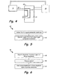
- Fig. 5 illustrates a flow diagram of a method for removing dissolved oxygen from a fuel using a surface-modified porous membrane.
- dissolved oxygen is removed from a fuel.
- Method 40 includes delivering fuel to an oxygen permeable membrane in step 42.
- fuel is delivered to oxygen permeable membrane 22 at a pressure between about 345 kPa (50 psi) to 1.4 MPa (200 psi).
- Oxygen permeable membrane 22 includes porous membrane 28 and oleophobic layer 30. Porous membrane 28 has pores 32 extending from a first side of porous membrane 28 to a second opposite side of porous membrane 28.
- Pores 32 have an average pore diameter less than or equal to about 0.06 microns.
- Oleophobic layer 30 is located on the first side of porous membrane 28. Together oleophobic layer 30 and porous membrane 28 allow oxygen to cross oxygen permeable membrane 22 but substantially prevent fuel from crossing oxygen permeable membrane 22.
- oxygen is removed from the fuel using oxygen permeable membrane 22.
- Fig. 6 illustrates a flow diagram of a method for modifying a surface of a porous membrane used to deoxygenate fuel.
- Method 46 includes depositing an oleophobic treatment agent on a first side of a porous membrane in step 48.
- Porous membrane 28 has pores 32 extending from the first side of porous membrane to an opposite second side of porous membrane 28.
- Pores 32 have an average pore diameter less than or equal to about 0.06 microns.
- the oleophobic treatment agent includes fluorosilicones and perfluorinated amphiphilic compounds.
- the oleophobic treatment agent is perfluorododecanoic acid. In an alternate embodiment, the oleophobic treatment agent is tridecafluorooctyl triethoxysilane.
- solvent used during oleophobic treatment agent deposition step 48 is removed. Any solvent is removed using heat, vacuum or their combination.
- the treated porous membrane is heated to form oleophobic layer 30 on the first side of porous membrane 28.
Landscapes
- Chemical & Material Sciences (AREA)
- Chemical Kinetics & Catalysis (AREA)
- Engineering & Computer Science (AREA)
- Manufacturing & Machinery (AREA)
- Water Supply & Treatment (AREA)
- Inorganic Chemistry (AREA)
- Physics & Mathematics (AREA)
- Optics & Photonics (AREA)
- Aviation & Aerospace Engineering (AREA)
- Separation Using Semi-Permeable Membranes (AREA)
- Degasification And Air Bubble Elimination (AREA)
Abstract
Description
- Because of its relative abundance in the air of the atmosphere, relatively large quantities of oxygen, as well as nitrogen and other gases, readily dissolve into various liquid media. The presence of dissolved oxygen, in particular, in some liquids, such as hydrocarbon fuels, may be objectionable because it supports oxidation reactions that yield undesirable by-products.
- For instance, jet fuel in aircraft may be used as a coolant for various systems in the aircraft. When air-saturated fuel is heated to temperatures above about 120 °C (250 °F) to 150 °C (300 °F), the dissolved oxygen reacts to form free radical species (coke precursors) which initiate and propagate other autoxidation reactions leading to the formation of objectionable deposits, called "coke" or "coking". As fuel temperature increases beyond about 150 °C (300 °F), the process of autoxidation consumes oxygen and forms carbonaceous deposits. The temperature at which autoxidation begins differs for different fuels. These autoxidation reactions may also occur in jet fuel as it is heated immediately prior to injection for combustion, such that deposits may occur in the injectors. In any event, the formation of such deposits impairs the normal functioning of a fuel delivery system, either with respect to an intended heat exchange function or the efficient injection of fuel.
- A fuel stabilization unit reduces the amount of oxygen dissolved within a fuel. Reducing the amount of oxygen in a fuel increases the maximum allowable temperature of the fuel, thereby increasing its heat sink capacity when used for cooling components onboard the aircraft. One method of removing dissolved oxygen from fuels is by using a semi-permeable membrane deoxygenator. In a membrane deoxygenator, fuel is pumped over an oxygen permeable membrane. As the fuel passes over the membrane, a partial oxygen pressure differential across the membrane promotes the transport of oxygen out of the fuel through the membrane. Exemplary deoxygenators remove oxygen to a level at least below that at which significant coking would otherwise occur. As used herein, "significant coking" is the minimum amount of coking which, if it occurred in the interval between normal intended maintenance events for such portions of the fuel system, would be viewed as objectionable. Such coking occurs most readily in the portions of the fuel system having high temperatures and/or constricted flow paths.
- A fuel deoxygenation system includes an oxygen permeable membrane having a porous membrane and an oleophobic layer. The porous membrane has pores extending from a first side of the porous membrane to an opposite second side of the porous membrane. The pores of the porous membrane have an average pore diameter less than or equal to about 0.06 microns. The oleophobic layer is located on the first side of the porous membrane. The oleophobic layer and the porous membrane allow oxygen to cross the oxygen permeable membrane but substantially prevent fuel from crossing the oxygen permeable membrane.
- A method for removing dissolved oxygen from a fuel includes delivering fuel to an oxygen permeable membrane and removing oxygen from the fuel using the oxygen permeable membrane. The oxygen permeable membrane includes a porous membrane and an oleophobic layer. The porous membrane has pores extending from a first side of the porous membrane to an opposite second side of the porous membrane. The pores of the porous membrane have an average pore diameter less than or equal to about 0.06 microns. The oleophobic layer is located on the first side of the porous membrane. The oleophobic layer and the porous membrane allow oxygen to cross the oxygen permeable membrane but substantially prevent fuel from crossing the oxygen permeable membrane.
- A method for modifying a surface of a porous membrane used to deoxygenate fuel includes depositing an oleophobic treatment agent on a first side of the porous membrane, removing solvent used during deposition of the oleophobic treatment agent and heating the porous membrane to form an oleophobic layer on the first side of the porous membrane. The porous membrane has pores extending from the first side of the porous membrane to an opposite second side of the porous membrane. The pores of the porous membrane have an average pore diameter less than or equal to about 0.06 microns.
-
-
Fig. 1 is a simplified schematic of a fuel delivery system. -
Fig. 2A is a simplified depiction of an unmodified porous membrane. -
Fig. 2B is a simplified depiction of a surface-modified porous membrane having an average pore size diameter of less than 0.06 microns. -
Fig. 3 is a simplified depiction of a surface modified porous membrane having an average pore size diameter of greater than 0.06 microns. -
Fig. 4 is a simplified schematic of a fuel stabilization unit with a condenser. -
Fig. 5 is a simplified flow diagram of a method for removing dissolved oxygen from a fuel using a surface-modified porous membrane. -
Fig. 6 is a simplified flow diagram of a method for modifying a surface of a porous membrane used to deoxygenate fuel. - The present invention provides a fuel deoxygenation system in which a surface-modified porous membrane serves as the oxygen permeable membrane for removing dissolved oxygen from a fuel. The oleophobicity of the porous membrane is increased to prevent fuel from crossing the oxygen permeable membrane along with the oxygen. For porous membranes with large average pore sizes, additional modifications to the porous membrane are made. The present invention also provides a method for removing dissolved oxygen from a fuel and a method for modifying a surface of a porous membrane used to deoxygenate fuel.
-
Fig. 1 illustrates a simplified schematic of one embodiment of a fuel delivery system.Fuel delivery system 10 delivers fuel togas turbine engine 12. Fuel fromfuel supply 14 flows throughfuel flow path 16 to fuel stabilization unit (FSU) 18 where the fuel is deoxygenated. The fuel continues to flow throughfuel path 16, exiting FSU 18, and is discharged fromfuel nozzles 20 intoengine 12. - FSU 18 removes oxygen and other constituents (such as nitrogen and light hydrocarbons) from the fuel flowing through FSU 18. Within FSU 18,
fuel flow path 16 is bounded by oxygenpermeable membrane 22 and passes throughvacuum chamber 24.Vacuum chamber 24 communicates withvacuum source 26.Vacuum source 26 is used to create a vacuum invacuum chamber 24, reducing the partial pressure of oxygen on the vacuum side of oxygenpermeable membrane 22. - Oxygen
permeable membrane 22 separates oxygen from the fuel flowing throughfuel flow path 16 inFSU 18. Oxygen and other small molecules can cross oxygenpermeable membrane 22, while the main fuel components cannot. Oxygen transmits across oxygenpermeable membrane 22 depending on the oxygen partial pressures on the fuel side (within fuel flow path 16) and the vacuum side (inside vacuum chamber 24) of the membrane. For example, when the partial pressure of oxygen is lower invacuum chamber 24 than the partial pressure of oxygen infuel flow path 16, oxygen from the fuel flowing infuel flow path 16 crosses oxygenpermeable membrane 22 to entervacuum chamber 24. Thus, reducing the partial pressure of oxygen on the vacuum side of oxygenpermeable membrane 22 so that it is lower than the partial pressure of oxygen on the fuel side of the membrane enables deoxygenation of fuel. - According to the present invention, oxygen
permeable membrane 22 is a surface-modified porous membrane.Fig. 2A illustrates an unmodified porous membrane.Porous membrane 28 includespores 32.Fig. 2B illustrates one embodiment of a surface-modified porous membrane having an average pore size diameter of less than 0.06 microns. Oxygenpermeable membrane 22 includesporous membrane 28 andoleophobic layer 30.Porous membrane 28 includespores 32.Pores 32 are located throughoutporous membrane 28 and eachpore 32 extends essentially through the entire thickness ofporous membrane 28 either as a single channel or via communication with adjacent pores or pores emanating from the opposite side ofporous membrane 28. Thus, eachpore 32 extends or interconnects with other pores to form a passage from one side ofporous membrane 28 to the opposite side ofporous membrane 28. The orientation and geometry ofpores 32 can vary (e.g., straight, angled, etc.), but a substantial number ofpores 32 inporous membrane 28 are continuous throughout the entirety of porous membrane 28 (i.e. a majority ofpores 32 do not "dead end" before reaching the opposite side of porous membrane 28).Porous membrane 28 can be a porous polymer material, a porous ceramic material, a porous metal or any combination thereof. In exemplary embodiments,porous membrane 28 has a thickness between about 50 nanometers and about 4 microns.Porous membrane 28 can be supported by a macroporous layer such as a non-woven sheet or similar structure for enhanced dimensional stability. -
Oleophobic layer 30 is a layer deposited on one side ofporous membrane 28.Oleophobic layer 30 increases the oleophobicity of one side of oxygen permeable membrane 22 (the side that comes into contact with the fuel). By increasing the oleophobicity of oxygenpermeable membrane 22, oxygenpermeable membrane 22 deters fuel from interacting with and crossing oxygenpermeable membrane 22. At elevated temperatures and pressures, significant amounts of fuel may cross untreatedporous membrane 28, but addingoleophobic layer 30 toporous membrane 28 considerably reduces the amount of fuel that is able to cross oxygenpermeable membrane 22.Oleophobic layer 30 does not substantially affect permeation of oxygen across oxygenpermeable membrane 22. - In one embodiment,
oleophobic layer 30 is produced using a silicone-based compound. Silicone-based compounds include fluorosilicones such as fluoroalkyl silanes. One exemplary fluoroalkyl silane is tridecafluorooctyl triethoxysilane. In another embodiment,oleophobic layer 30 is produced using a perfluorinated amphiphilic compound. Amphiphilic compounds possess both hydrophilic and oleophilic (lipophilic) properties. Perfluorinated amphiphilic compounds include perfluorinated carboxylic acids. One exemplary perfluorinated amphiphilic compound is perfluorododecanoic acid, (CF3)(CF2)10COOH. -
Oleophobic layer 30 can be applied toporous membrane 28 in various ways. In one embodiment, an oleophobic solution is deposited onporous membrane 28, followed by drying and curing to produceoleophobic layer 30. In another embodiment,oleophobic layer 30 is a stretched film and is applied toporous membrane 28 as a film. In yet another embodiment,oleophobic layer 30 is applied to porous membrane as a track-etched membrane. In exemplary embodiments,oleophobic layer 30 has a thickness between a single monolayer and about 1 micron. - Formation of
oleophobic layer 30 can generally be accomplished by simple deposition of the amphiphilic compound (for example, solution casting and subsequent drying of the solvent) or by chemically reacting the hydrophilic end of the amphiphilic compound with appropriate functional groups on the surface ofporous membrane 28, thus creating a permanent bond between the oleophobic agent and the membrane surface. While simple deposition is adequate for single-use items and other applications where long-term durability is not a concern, a more permanent bond betweenporous membrane 28 andoleophobic layer 30 is useful for FSU applications. Regarding the selection of a method for chemically bondingoleophobic layer 30 onto the surface ofporous membrane 28, two examples are provided: one example for an inorganicporous membrane 28 and one example for an organic (polymer-based)porous membrane 28. - Inorganic materials, particularly metal oxides, typically contain surface hydroxyl (OH) groups, which can be reacted with the carboxylic acid of an amphiphilic molecule possessing an oleophobic end, such as perfluorododecanoic acid. The reaction between surface OH groups and the carboxylic acid (COOH) group of the perfluorododecanoic acid is an esterification reaction, typically carried out at elevated temperature in the presence of sulfuric acid as a catalyst. The concentration of the OH groups at the surface varies substantially among different materials. Those materials exhibiting the highest concentrations, such as alumino-silicates, are particularly suitable as they will yield the highest concentration of grafted esters of perfluorododecanoic acid, which in turn will result in increased oleophobicity.
- Regarding polymeric porous membranes, one approach to bonding
oleophobic layer 30 toporous membrane 28 is to apply techniques developed for chemical surface modification of textile fibers to render them oleophobic, as described for example inU.S. Patent No. 5,350,795 . Another approach is to utilize atmospheric plasma treatments such as Enercon's Plasma3™ (http://www.enerconind.com/treating/products/wide-web/plasma3.aspx) or Dow Corning's Plasma Solutions (http://www.dowcoming.com/content/webabstract/ABS_26-1313-01.asp). In this technique, the polymer surface ofporous membrane 28 is first activated with ionized gas and subsequently grafted with an oleophobic treatment agent to formoleophobic layer 30. The oleophobic treatment agent can be in gaseous or liquid form, depending on the technology developed by the plasma treatment manufacturer. - Merely applying
oleophobic layer 30 toporous membrane 28 does not ensure that significant amounts of fuel will not cross oxygenpermeable membrane 22. Fuel is typically delivered toFSU 18 at pressures ranging from 345 kPa (50 psi) to 1.4 MPa (200 psi). At these pressure conditions, some amount of fuel will cross oxygenpermeable membrane 22 unless the average pore size ofpores 32 inporous membrane 28 are kept below a threshold level. In exemplary embodiments the average pore diameter ofpores 32 is between about 0.002 microns and about 0.06 microns. Where the average pore diameter ofpores 32 is about 0.06 microns or smaller, oxygen permeable membrane 22 (porous membrane 28 with oleophobic treatment layer 30) is suitable for deoxygenating fuel delivered to oxygenpermeable membrane 22 at pressures up to about 1380 kPa (200 psi) without allowing a substantial amount of fuel to cross oxygenpermeable membrane 22.Fig. 2B illustrates oxygenpermeable membrane 22 in which pores 32 ofporous membrane 28 have an average pore diameter between about 0.002 microns and about 0.06 microns. - Where the average pore diameter of
pores 32 inporous membrane 28 is greater than 0.06 microns, additional modifications toporous membrane 28 can be made prior to application ofoleophobic layer 30. In one embodiment, the average pore diameter ofpores 32 inporous membrane 28 is reduced by combiningporous membrane 28 with a second porous membrane to reduce the average pore diameter. -
Fig. 3 illustrates one embodiment of a surface-modified porous membrane having an average pore size diameter greater than 0.06 microns. Oxygenpermeable membrane 22A includesporous membrane 28A, secondporous membrane 34 andoleophobic layer 30.Porous membrane 28A containspores 32 having an average pore diameter greater than 0.06 microns. Secondporous membrane 34 containspores 36 having an average pore diameter less than or equal to 0.06 microns. In exemplary embodiments the average pore diameter ofpores 36 is between about 0.005 microns and about 0.06 microns. Secondporous membrane 34 bridges pores 32 ofporous membrane 28A, reducing the average pore size of the combined membrane. In order for secondporous membrane 34 to effectively bridge pores 32 ofporous membrane 28A, the average pore diameter ofpores 32 ofporous membrane 28A must generally be between about 0.07 microns and about 0.2 microns. Porous membranes having average pore diameters greater than about 0.2 microns cannot be effectively bridged. In such cases, secondporous membrane 34 would fill inpores 32 rather than layer across the surface ofporous membrane 28A. Once secondporous membrane 34 has been applied toporous membrane 28A,oleophobic layer 30 can be applied to secondporous membrane 34 as described above with respect toporous membrane 28. - Even with
oleophobic layer 30, small amounts of fuel vapor may still permeate oxygenpermeable membrane 22. A condenser is used to condense any fuel vapor that crosses oxygenpermeable membrane 22.Fig. 4 illustrates a fuel stabilization unit with a condenser.FSU 18 includescondenser 38.Condenser 38 communicates with the oxygen receiving side of FSU 18 (vacuum chamber 24). Fuel vapor that crosses oxygenpermeable membrane 22 is condensed bycondenser 38. The condensed fuel is then delivered back tofuel supply 14. In one embodiment,condenser 38 is operated based on vapor-compression refrigeration. Alternatively,condenser 38 is a thermoelectric device. - The present invention can be used to remove dissolved oxygen from a fuel.
Fig. 5 illustrates a flow diagram of a method for removing dissolved oxygen from a fuel using a surface-modified porous membrane. According tomethod 40, dissolved oxygen is removed from a fuel.Method 40 includes delivering fuel to an oxygen permeable membrane instep 42. In exemplary embodiments fuel is delivered to oxygenpermeable membrane 22 at a pressure between about 345 kPa (50 psi) to 1.4 MPa (200 psi). Oxygenpermeable membrane 22 includesporous membrane 28 andoleophobic layer 30.Porous membrane 28 haspores 32 extending from a first side ofporous membrane 28 to a second opposite side ofporous membrane 28.Pores 32 have an average pore diameter less than or equal to about 0.06 microns.Oleophobic layer 30 is located on the first side ofporous membrane 28. Togetheroleophobic layer 30 andporous membrane 28 allow oxygen to cross oxygenpermeable membrane 22 but substantially prevent fuel from crossing oxygenpermeable membrane 22. In step 44, oxygen is removed from the fuel using oxygenpermeable membrane 22. - The present invention can also be used to modify a surface of a porous membrane used for deoxygenating fuel.
Fig. 6 illustrates a flow diagram of a method for modifying a surface of a porous membrane used to deoxygenate fuel.Method 46 includes depositing an oleophobic treatment agent on a first side of a porous membrane instep 48.Porous membrane 28 haspores 32 extending from the first side of porous membrane to an opposite second side ofporous membrane 28.Pores 32 have an average pore diameter less than or equal to about 0.06 microns. The oleophobic treatment agent includes fluorosilicones and perfluorinated amphiphilic compounds. In one exemplary embodiment, the oleophobic treatment agent is perfluorododecanoic acid. In an alternate embodiment, the oleophobic treatment agent is tridecafluorooctyl triethoxysilane. Instep 50, solvent used during oleophobic treatmentagent deposition step 48 is removed. Any solvent is removed using heat, vacuum or their combination. Instep 52, the treated porous membrane is heated to formoleophobic layer 30 on the first side ofporous membrane 28. - While the invention has been described with reference to an exemplary embodiment(s), it will be understood by those skilled in the art that various changes may be made and equivalents may be substituted for elements thereof without departing from the scope of the invention. In addition, many modifications may be made to adapt a particular situation or material to the teachings of the invention without departing from the essential scope thereof. Therefore, it is intended that the invention not be limited to the particular embodiment(s) disclosed, but that the invention will include all embodiments falling within the scope of the appended claims.
Claims (15)
- A fuel deoxygenation system comprising an oxygen permeable membrane (22; 22A) comprising:a porous membrane (28; 28A) having pores (32) that create a passage extending from a first side of the porous membrane (28; 28A) to an opposite second side of the porous membrane (28; 28A), wherein the pores (32) of the porous membrane (28; 28A) have an average pore diameter less than or equal to about 0.06 microns; andan oleophobic layer (30) located on the first side of the porous membrane (28; 28A), wherein the oleophobic layer (30) and the porous membrane (28; 28A) allow oxygen to cross the oxygen permeable membrane (22; 22A) but substantially prevent fuel from crossing the oxygen permeable membrane (22; 22A).
- The fuel deoxygenation system of claim 1, wherein the oleophobic layer (30) is produced using a fluorosilicone.
- The fuel deoxygenation system of claim 1, wherein the oleophobic layer (30) is produced using a perfluorinated amphiphilic compound, and optionally wherein the oleophobic layer (30) is produced using a perfluorinated carboxylic acid.
- The fuel deoxygenation system of any of claims 1 to 3, further comprising a condenser (38) for liquefying fuel vapor that crosses the oxygen permeable membrane (22; 22A).
- The fuel deoxygenation system of any preceding claim, further comprising a second porous membrane (34) having pores (36) that create a passage extending from a first side of the second porous membrane (34) to an opposite second side of the second porous membrane (34), wherein the pores (36) of the second porous membrane (34) have an average pore diameter greater than about 0.06 microns, and wherein the porous membrane (28A) having an average pore diameter less than or equal to about 0.06 microns is formed on the first side of the second porous membrane (34).
- A method for removing dissolved oxygen from a fuel, the method comprising delivering fuel to an oxygen permeable membrane (22; 22A) comprising:a porous membrane (28; 28A) having pores (32) that create a passage extending from a first side of the porous membrane (28; 28A) to an opposite second side of the porous membrane (28; 28A), wherein the pores (32) of the porous membrane (28; 28A) have an average pore diameter less than or equal to about 0.06 microns; andan oleophobic layer (30) located on the first side of the porous membrane (28; 28A), wherein the oleophobic layer (30) and the porous membrane (28; 28A) allow oxygen to cross the oxygen permeable membrane (22; 22A) but substantially prevent fuel from crossing the oxygen permeable membrane (22; 22A); andremoving oxygen from the fuel using the oxygen permeable membrane (22; 22A).
- The method of claim 6, wherein fuel is delivered to the oxygen permeable membrane (22; 22A) at pressure between about 345 kPa (50 psi) and about 1.4 MPa (200 psi).
- The method of claim 6 or 7, wherein the oleophobic layer (30) is produced using a perfluorinated carboxylic acid.
- The fuel deoxygenation system or method of any preceding claim, wherein the oleophobic layer (30) is:a stretched film; ora track-etched membrane.
- The method of any of claims 6 to 9, wherein the oxygen permeable membrane (22A) further comprises a second porous membrane (34) located on the second side of the porous membrane (28A), wherein the second porous membrane (34) has pores (36) that create a passage extending from a first side of the second porous membrane (34) to an opposite second side of the second porous membrane (34), wherein the pores (36) of the second porous membrane (34) have an average pore diameter greater than about 0.06 microns.
- The fuel deoxygenation system or method of claim 5 or 10, wherein the pores (36) of the second porous membrane have an average pore diameter between about 0.07 microns and about 0.2 microns.
- The method of any of claims 6 to 11, further comprising condensing fuel vapor that crosses the oxygen permeable membrane (22; 22A).
- A method for modifying a surface of a porous membrane (28; 28A) used to deoxygenate fuel, the method comprising:depositing an oleophobic treatment agent on a first side of the porous membrane (28; 28A), wherein the porous membrane (28; 28A) comprises pores (32) that create a passage extending from the first side of the porous membrane (28; 28A) to an opposite second side of the porous membrane (28; 28A), and wherein the pores (32) of the porous membrane (28; 28A) have an average pore diameter less than or equal to about 0.06 microns,removing solvent used during deposition of the oleophobic treatment agent; andheating the porous membrane (28; 28A) to form an oleophobic layer (30) on the first side of the porous membrane (28; 28A).
- The method of claim 13, the porous membrane (28A) is deposited on a first side of a second porous membrane (34) having pores (36) that create a passage extending from the first side of the second porous membrane (34) to an opposite second side of the second porous membrane (34), wherein the pores (36) of the second porous membrane (34) have an average pore diameter greater than about 0.06 microns.
- The method of claim 13 or 14, wherein the oleophobic treatment agent is perfluorododecanoic acid.
Applications Claiming Priority (1)
| Application Number | Priority Date | Filing Date | Title |
|---|---|---|---|
| US13/173,864 US8741029B2 (en) | 2011-06-30 | 2011-06-30 | Fuel deoxygenation using surface-modified porous membranes |
Publications (2)
| Publication Number | Publication Date |
|---|---|
| EP2540366A2 true EP2540366A2 (en) | 2013-01-02 |
| EP2540366A3 EP2540366A3 (en) | 2013-03-06 |
Family
ID=46458251
Family Applications (1)
| Application Number | Title | Priority Date | Filing Date |
|---|---|---|---|
| EP12174443A Withdrawn EP2540366A3 (en) | 2011-06-30 | 2012-06-29 | Fuel deoxygenation using surface-modified porous membranes |
Country Status (2)
| Country | Link |
|---|---|
| US (1) | US8741029B2 (en) |
| EP (1) | EP2540366A3 (en) |
Cited By (1)
| Publication number | Priority date | Publication date | Assignee | Title |
|---|---|---|---|---|
| US10215097B2 (en) | 2015-12-08 | 2019-02-26 | General Electric Company | Thermal management system |
Families Citing this family (5)
| Publication number | Priority date | Publication date | Assignee | Title |
|---|---|---|---|---|
| US10029191B2 (en) | 2016-09-15 | 2018-07-24 | Hamilton Sundstrand Corporation | Liquid-dissolved gas separators |
| US11000784B2 (en) | 2017-08-22 | 2021-05-11 | Hamilton Sunstrand Corporation | Vacuum system for fuel degassing |
| US10118109B1 (en) | 2017-08-22 | 2018-11-06 | Hamilton Sundstrand Corporation | Vacuum system for fuel degassing system |
| US10556193B2 (en) | 2017-09-15 | 2020-02-11 | Hamilton Sundstrand Corporation | Integrated O2RU system |
| US11491421B2 (en) | 2018-01-22 | 2022-11-08 | Hamilton Sundstrand Corporation | Valve controlled vacuum system |
Citations (1)
| Publication number | Priority date | Publication date | Assignee | Title |
|---|---|---|---|---|
| US5350795A (en) | 1991-07-10 | 1994-09-27 | Minnesota Mining And Manufacturing Company | Aqueous oil and water repellent compositions which cure at ambient temperature |
Family Cites Families (12)
| Publication number | Priority date | Publication date | Assignee | Title |
|---|---|---|---|---|
| US4554076A (en) * | 1982-08-18 | 1985-11-19 | Georgia Tech Research Corporation | Method of modifying membrane surface with oriented monolayers of amphiphilic compounds |
| EP0164025B1 (en) * | 1984-05-24 | 1989-02-01 | TERUMO KABUSHIKI KAISHA trading as TERUMO CORPORATION | Hollow fiber membrane type oxygenator and method for manufacturing same |
| JP2893530B2 (en) * | 1988-12-08 | 1999-05-24 | ジャパンゴアテックス株式会社 | Degassing membrane and degassing process |
| CA2064002C (en) | 1989-07-24 | 2001-11-27 | Yitzchak Kenigsberg | Process for treating a porous substrate to achieve improved water and oil repellency |
| US6196708B1 (en) | 1998-05-14 | 2001-03-06 | Donaldson Company, Inc. | Oleophobic laminated articles, assemblies of use, and methods |
| US6315815B1 (en) | 1999-12-16 | 2001-11-13 | United Technologies Corporation | Membrane based fuel deoxygenator |
| US6939392B2 (en) | 2003-04-04 | 2005-09-06 | United Technologies Corporation | System and method for thermal management |
| US8070859B2 (en) | 2004-02-25 | 2011-12-06 | Membrane Technology And Research, Inc. | Method for producing a non-porous membrane |
| US7153343B2 (en) * | 2004-03-24 | 2006-12-26 | United Technologies Corporation | Fuel deoxygenation system |
| DE102008016158A1 (en) * | 2008-03-28 | 2009-10-01 | Forschungszentrum Jülich GmbH | Oxygen permeable membrane and process for its preparation |
| US20100024898A1 (en) | 2008-07-29 | 2010-02-04 | General Electric Company | Fuel tank vent including a membrane separator |
| US20100024651A1 (en) | 2008-07-30 | 2010-02-04 | General Electric Company | Membrane contactor systems for gas-liquid contact |
-
2011
- 2011-06-30 US US13/173,864 patent/US8741029B2/en active Active
-
2012
- 2012-06-29 EP EP12174443A patent/EP2540366A3/en not_active Withdrawn
Patent Citations (1)
| Publication number | Priority date | Publication date | Assignee | Title |
|---|---|---|---|---|
| US5350795A (en) | 1991-07-10 | 1994-09-27 | Minnesota Mining And Manufacturing Company | Aqueous oil and water repellent compositions which cure at ambient temperature |
Cited By (2)
| Publication number | Priority date | Publication date | Assignee | Title |
|---|---|---|---|---|
| US10215097B2 (en) | 2015-12-08 | 2019-02-26 | General Electric Company | Thermal management system |
| US11098647B2 (en) | 2015-12-08 | 2021-08-24 | General Electric Company | Thermal management system |
Also Published As
| Publication number | Publication date |
|---|---|
| US8741029B2 (en) | 2014-06-03 |
| EP2540366A3 (en) | 2013-03-06 |
| US20130000180A1 (en) | 2013-01-03 |
Similar Documents
| Publication | Publication Date | Title |
|---|---|---|
| US8741029B2 (en) | Fuel deoxygenation using surface-modified porous membranes | |
| EP1559902B1 (en) | Method for preventing fuel infiltration into microporous polymer membranes | |
| JP6211091B2 (en) | Flammability reduction method and system for aircraft fuel tank using membrane and air separation method | |
| Tseng et al. | Superoleophilic and superhydrophobic carbon membranes for high quantity and quality separation of trace water-in-oil emulsions | |
| EP1568403A1 (en) | Method for producing a non-porous membrane | |
| KR20090038901A (en) | Improved membrane separation process using mixed vapor-liquid feed | |
| US20020007587A1 (en) | Process for purifying a liquid hydrocarbon fuel | |
| EP2129747A1 (en) | Method for reducing the mercury content of natural gas condensate and natural gas processing plant | |
| Wu et al. | Separation and concentration of ionic liquid aqueous solution by vacuum membrane distillation | |
| WO2005042672A1 (en) | Process for upgrading a liquid hydrocarbon stream with a non-porous or nano-filtration membrane | |
| WO2015080123A1 (en) | Waste water treatment method, membrane distillation module, and waste water treatment device | |
| US20150005468A1 (en) | High permeability copolyimide gas separation membranes | |
| RU2726354C1 (en) | Highly elastic polymer membranes for separation process | |
| Xiao et al. | Bioinspired Janus membrane of polyacrylonitrile/poly (vinylidene fluoride)@ poly (vinylidene fluoride)-methyltriethoxysilane for oil-water separation | |
| CN103657457B (en) | Composite silicone rubber membrane, Its Preparation Method And Use | |
| US20200197834A1 (en) | Composite hollow fiber membranes for jet fuel de-oxygenation | |
| RU2311441C2 (en) | Continuous method of separation of the colored masses and-or the asphaltene impurities from the hydrocarbon mixture | |
| US20190022557A1 (en) | Fuel tank de-oxygenation system | |
| US10118124B2 (en) | Integrated membrane-pyrolysis systems and methods | |
| Xu et al. | Revealing the selective separation of organics from salty solution in novel aqueous-aqueous membrane extraction co-driven by concentration and pressure difference | |
| US20180272261A1 (en) | Filter medium | |
| EP1372822B1 (en) | Membrane pervaporation and vapor permeation process | |
| EP3434347A1 (en) | Fuel tank de-oxygenation system | |
| CN108714372B (en) | Treatment method for coal chemical industry wastewater | |
| Shalaby et al. | Removal of Phenol from Sour Water by Poly (vinyl Alcohol)/Polyamide‐Reverse Osmosis Membranes |
Legal Events
| Date | Code | Title | Description |
|---|---|---|---|
| PUAI | Public reference made under article 153(3) epc to a published international application that has entered the european phase |
Free format text: ORIGINAL CODE: 0009012 |
|
| AK | Designated contracting states |
Kind code of ref document: A2 Designated state(s): AL AT BE BG CH CY CZ DE DK EE ES FI FR GB GR HR HU IE IS IT LI LT LU LV MC MK MT NL NO PL PT RO RS SE SI SK SM TR |
|
| AX | Request for extension of the european patent |
Extension state: BA ME |
|
| PUAL | Search report despatched |
Free format text: ORIGINAL CODE: 0009013 |
|
| AK | Designated contracting states |
Kind code of ref document: A3 Designated state(s): AL AT BE BG CH CY CZ DE DK EE ES FI FR GB GR HR HU IE IS IT LI LT LU LV MC MK MT NL NO PL PT RO RS SE SI SK SM TR |
|
| AX | Request for extension of the european patent |
Extension state: BA ME |
|
| RIC1 | Information provided on ipc code assigned before grant |
Ipc: B64D 37/32 20060101ALI20130128BHEP Ipc: B01D 67/00 20060101ALI20130128BHEP Ipc: B01D 19/00 20060101AFI20130128BHEP Ipc: B01D 61/02 20060101ALI20130128BHEP Ipc: B01D 69/10 20060101ALI20130128BHEP |
|
| 17P | Request for examination filed |
Effective date: 20130903 |
|
| RBV | Designated contracting states (corrected) |
Designated state(s): AL AT BE BG CH CY CZ DE DK EE ES FI FR GB GR HR HU IE IS IT LI LT LU LV MC MK MT NL NO PL PT RO RS SE SI SK SM TR |
|
| RAP1 | Party data changed (applicant data changed or rights of an application transferred) |
Owner name: UNITED TECHNOLOGIES CORPORATION |
|
| 17Q | First examination report despatched |
Effective date: 20170125 |
|
| STAA | Information on the status of an ep patent application or granted ep patent |
Free format text: STATUS: THE APPLICATION HAS BEEN WITHDRAWN |
|
| 18W | Application withdrawn |
Effective date: 20180913 |