EP2537642A1 - Robot fabricator - Google Patents
Robot fabricator Download PDFInfo
- Publication number
- EP2537642A1 EP2537642A1 EP12173306A EP12173306A EP2537642A1 EP 2537642 A1 EP2537642 A1 EP 2537642A1 EP 12173306 A EP12173306 A EP 12173306A EP 12173306 A EP12173306 A EP 12173306A EP 2537642 A1 EP2537642 A1 EP 2537642A1
- Authority
- EP
- European Patent Office
- Prior art keywords
- item
- manipulator
- fabrication
- head
- tool
- Prior art date
- Legal status (The legal status is an assumption and is not a legal conclusion. Google has not performed a legal analysis and makes no representation as to the accuracy of the status listed.)
- Withdrawn
Links
Images


Classifications
-
- B—PERFORMING OPERATIONS; TRANSPORTING
- B25—HAND TOOLS; PORTABLE POWER-DRIVEN TOOLS; MANIPULATORS
- B25J—MANIPULATORS; CHAMBERS PROVIDED WITH MANIPULATION DEVICES
- B25J9/00—Programme-controlled manipulators
- B25J9/0084—Programme-controlled manipulators comprising a plurality of manipulators
-
- B—PERFORMING OPERATIONS; TRANSPORTING
- B23—MACHINE TOOLS; METAL-WORKING NOT OTHERWISE PROVIDED FOR
- B23P—METAL-WORKING NOT OTHERWISE PROVIDED FOR; COMBINED OPERATIONS; UNIVERSAL MACHINE TOOLS
- B23P23/00—Machines or arrangements of machines for performing specified combinations of different metal-working operations not covered by a single other subclass
- B23P23/04—Machines or arrangements of machines for performing specified combinations of different metal-working operations not covered by a single other subclass for both machining and other metal-working operations
-
- B—PERFORMING OPERATIONS; TRANSPORTING
- B25—HAND TOOLS; PORTABLE POWER-DRIVEN TOOLS; MANIPULATORS
- B25J—MANIPULATORS; CHAMBERS PROVIDED WITH MANIPULATION DEVICES
- B25J9/00—Programme-controlled manipulators
- B25J9/16—Programme controls
- B25J9/1679—Programme controls characterised by the tasks executed
- B25J9/1682—Dual arm manipulator; Coordination of several manipulators
-
- B—PERFORMING OPERATIONS; TRANSPORTING
- B29—WORKING OF PLASTICS; WORKING OF SUBSTANCES IN A PLASTIC STATE IN GENERAL
- B29C—SHAPING OR JOINING OF PLASTICS; SHAPING OF MATERIAL IN A PLASTIC STATE, NOT OTHERWISE PROVIDED FOR; AFTER-TREATMENT OF THE SHAPED PRODUCTS, e.g. REPAIRING
- B29C64/00—Additive manufacturing, i.e. manufacturing of three-dimensional [3D] objects by additive deposition, additive agglomeration or additive layering, e.g. by 3D printing, stereolithography or selective laser sintering
- B29C64/10—Processes of additive manufacturing
- B29C64/106—Processes of additive manufacturing using only liquids or viscous materials, e.g. depositing a continuous bead of viscous material
-
- B—PERFORMING OPERATIONS; TRANSPORTING
- B29—WORKING OF PLASTICS; WORKING OF SUBSTANCES IN A PLASTIC STATE IN GENERAL
- B29C—SHAPING OR JOINING OF PLASTICS; SHAPING OF MATERIAL IN A PLASTIC STATE, NOT OTHERWISE PROVIDED FOR; AFTER-TREATMENT OF THE SHAPED PRODUCTS, e.g. REPAIRING
- B29C64/00—Additive manufacturing, i.e. manufacturing of three-dimensional [3D] objects by additive deposition, additive agglomeration or additive layering, e.g. by 3D printing, stereolithography or selective laser sintering
- B29C64/20—Apparatus for additive manufacturing; Details thereof or accessories therefor
- B29C64/227—Driving means
- B29C64/232—Driving means for motion along the axis orthogonal to the plane of a layer
-
- B—PERFORMING OPERATIONS; TRANSPORTING
- B29—WORKING OF PLASTICS; WORKING OF SUBSTANCES IN A PLASTIC STATE IN GENERAL
- B29C—SHAPING OR JOINING OF PLASTICS; SHAPING OF MATERIAL IN A PLASTIC STATE, NOT OTHERWISE PROVIDED FOR; AFTER-TREATMENT OF THE SHAPED PRODUCTS, e.g. REPAIRING
- B29C64/00—Additive manufacturing, i.e. manufacturing of three-dimensional [3D] objects by additive deposition, additive agglomeration or additive layering, e.g. by 3D printing, stereolithography or selective laser sintering
- B29C64/20—Apparatus for additive manufacturing; Details thereof or accessories therefor
- B29C64/227—Driving means
- B29C64/236—Driving means for motion in a direction within the plane of a layer
-
- B—PERFORMING OPERATIONS; TRANSPORTING
- B29—WORKING OF PLASTICS; WORKING OF SUBSTANCES IN A PLASTIC STATE IN GENERAL
- B29C—SHAPING OR JOINING OF PLASTICS; SHAPING OF MATERIAL IN A PLASTIC STATE, NOT OTHERWISE PROVIDED FOR; AFTER-TREATMENT OF THE SHAPED PRODUCTS, e.g. REPAIRING
- B29C64/00—Additive manufacturing, i.e. manufacturing of three-dimensional [3D] objects by additive deposition, additive agglomeration or additive layering, e.g. by 3D printing, stereolithography or selective laser sintering
- B29C64/30—Auxiliary operations or equipment
- B29C64/386—Data acquisition or data processing for additive manufacturing
- B29C64/393—Data acquisition or data processing for additive manufacturing for controlling or regulating additive manufacturing processes
-
- B—PERFORMING OPERATIONS; TRANSPORTING
- B33—ADDITIVE MANUFACTURING TECHNOLOGY
- B33Y—ADDITIVE MANUFACTURING, i.e. MANUFACTURING OF THREE-DIMENSIONAL [3-D] OBJECTS BY ADDITIVE DEPOSITION, ADDITIVE AGGLOMERATION OR ADDITIVE LAYERING, e.g. BY 3-D PRINTING, STEREOLITHOGRAPHY OR SELECTIVE LASER SINTERING
- B33Y50/00—Data acquisition or data processing for additive manufacturing
- B33Y50/02—Data acquisition or data processing for additive manufacturing for controlling or regulating additive manufacturing processes
-
- B—PERFORMING OPERATIONS; TRANSPORTING
- B33—ADDITIVE MANUFACTURING TECHNOLOGY
- B33Y—ADDITIVE MANUFACTURING, i.e. MANUFACTURING OF THREE-DIMENSIONAL [3-D] OBJECTS BY ADDITIVE DEPOSITION, ADDITIVE AGGLOMERATION OR ADDITIVE LAYERING, e.g. BY 3-D PRINTING, STEREOLITHOGRAPHY OR SELECTIVE LASER SINTERING
- B33Y30/00—Apparatus for additive manufacturing; Details thereof or accessories therefor
Definitions
- material can only be deposited in areas in which there is already a base on which to deposit material. If the product to be printed requires an overhang, or becomes larger on a subsequent layer, a support structure is used to support the material that extends past the base on the previous plane. The support structure is removed after printing is complete, requiring extra processing and human involvement in the manufacturing steps. Human involvement in manufacturing steps increases production costs and creates increased factory safety risks. The cost of the support material also increases production costs.
- connectors and fasteners are used to secure product components together, and seams are created when product components are fused together. Connectors, fasteners, seams, and similar interfaces are frequently a source of failure in the end product.
- a fabrication device that reduces the number of connectors, fasteners, seams, and similar component interfaces increases the quality of the end product and reduces product failure.
- Traditional 3D printers require significant effort to produce a product design, and may require human intervention to assemble a finished product.
- a device that can fabricate a finished product from a design without any expert help or intervention increases both efficiency and product production possibilities.
- the systems and methods described herein decrease manufacturing costs, improve product quality, and improve factory safety by reducing the need for human labor during manufacture and more fully automating the manufacture and assembly processes.
- the systems and methods described herein include a fabrication machine/method that fuses additive and subtractive manufacturing with in-situ component placement to provide completely autonomous all-in-one product manufacturing.
- Product fabrication is centered around a six-axis industrial robotic manipulator (primary manipulator) that handles the product from seed component to mature product.
- the primary manipulator positions the product for manufacturing operations such as additive and subtractive manufacturing (3D printing, milling and drilling).
- a secondary manipulator handles component pick-and-place and secondary manufacturing operations such as wire placement and hardware testing.
- all-in-one product manufacturing increases the ability to produce prototypes or small production runs of devices, since no human intervention is used, product design is simpler and production is more efficient.
- the systems and methods described herein include sensors, typically high precision sensors, that can measure parameters and characteristics of the device being manufactured while the process is taking place.
- the system includes a precision scanning device that will generate precise measurements of the device being fabricated.
- the system includes a laser and camera sensor system. Information collected by the sensor may be used by the device to adjust subsequent steps in the manufacturing process.
- in-situ monitoring provides quality control by inspecting and tuning the additive and subtractive processes. The feedback from the sensors allows the system to estimate product qualities, such as, for example, tolerances, dimensions, and mass.
- a fabrication system includes a tool-head for manufacturing, a first manipulator, and a second manipulator.
- the first manipulator supports and manipulates an item, and is configured to provide six-axes of movement for positioning of the item relative the tool-head.
- the second manipulator carries a component and orients the component at a select orientation relative to the item supported on the first manipulator.
- the tool-head is configured to add material to at least one of the item and the component.
- the first and second manipulators provide at least six axes of fabrication for the tool-head.
- the tool-head is configured to remove material from at least one of the item and the component.
- the tool-head is configured to add an adhesive material to at least one of the item and the component.
- the adhesive material is configured to secure the component to the item.
- the tool-head includes at least one of a fused deposition modeling print head, a milling head, and a robocasting extruder.
- the fabrication system includes a sensor configured to measure parameters of the item during manufacturing.
- the sensor may be a high precision sensor.
- the sensor includes a laser and camera system configured to generate measurements of the item.
- fabrication system includes a processor configured to adjust manufacturing processes in response to the measured parameters.
- the fabrication system includes a processor configured to determine how to move at least one of the first manipulator and the second manipulator.
- the processor is configured to use a hierarchical task network to determine how to manufacture a product using the first manipulator, the second manipulator, and the tool-head.
- the item includes hardware, and the second manipulator is configured to test the hardware.
- the fabrication system includes a software component configured to use a three dimensional model of an end-product to generate a sequence of instructions for movements of at least one of the first manipulator, the second manipulator, and the tool-head.
- the sequence of instructions may instruct one or more of the first manipulator, the second manipulator, and the tool-head to move in a manner to fabricate the product.
- the fabrication system also includes a simulator configured to validate the sequence of instructions.
- the item is a previously printed object that is not in its original form
- the fabrication system includes a software component configured to use a three dimensional model of the item and a three dimensional model of the original form of the previously printed object to generate a sequence of instructions for movements of at least one of the first manipulator, the second manipulator, and the tool-head to return the previously printed object to its original form.
- the fabrication machine may be used to repair a previously printed object that has been damaged.
- a fabrication method includes supporting an item with a first manipulator, manipulating the item, using the first manipulator, along at least one of six axes of movement, to position the item with respect to a tool-head, manipulating a component, using a second manipulator, and orienting the component at a predetermined orientation relative to the item, attaching the component to the item, and adding material to at least one of the item and the component with the tool-head.
- the first and second manipulators provide at least six axes of fabrication for the tool-head.
- the method includes removing material from at least one of the item and the component with the tool-head.
- the method includes adding an adhesive material, using the tool-head, to at least one of the item and the component, and securing the component to the item.
- the method includes adding a wire to the item. The wire may be added by placing the wire using the second manipulator, or the wire may be added by adding material to the item using the tool-head to create the wire.
- the item includes hardware, and the method includes testing the hardware.
- the fabrication method further includes measuring parameters of the item during fabrication.
- the method includes adjusting, based on the measured parameters, at least one of manipulating the item, manipulating the component, and adding material.
- measuring parameters includes capturing images of the item during fabrication.
- the fabrication method further includes determining how to move at least one of the first manipulator and the second manipulator based at least in part on a finished product design. In one example, determining how to move at least one of the first manipulator and the second manipulator includes using a hierarchical task network to determine how to manufacture a product using the first manipulator, the second manipulator, and the tool-head.
- the fabrication method further includes receiving a three dimensional model of a product, and generating a sequence of instructions for moving at least one of the first manipulator, the second manipulator, and the tool-head to fabricate the product.
- the fabrication method may also include decomposing the three-dimensional model into a plurality of intermediate parts, and generating the sequence of instructions may include generating an intermediate sequence of instructions for each intermediate part.
- the fabrication method includes validating the sequence of instructions with a simulator.
- generating a sequence of instructions includes determining at least one parameter of at least one part of the product, and generating instructions for production that do not damage the at least one part of the product.
- the item is a previously printed object that is not in its original form
- the fabrication method further includes generating a three-dimensional model of the item, receiving a three dimensional model of the original form of the previously printed object, and generating a sequence of instructions for moving at least one of the first manipulator, the second manipulator, and the tool-head to return the previously printed object to its original form.
- the fabrication method is used to repair a previously printed object that has been damaged.
- a fabrication machine includes a six-axis industrial robotic manipulator and fuses additive and subtractive manufacturing with in-situ component placement to provide completely autonomous all-in-one product manufacturing.
- the six-axis robotic manipulator (the primary manipulator) positions an item for manufacturing operations (for example, 3D printing, milling and drilling).
- a secondary manipulator handles component pick-and-place and secondary manufacturing operations such as wire placement and hardware testing.
- the system may include one or more sensors that can measure parameters and characteristics of the product being manufactured while the process is taking place.
- the system includes a precision visual scanning device that will generate precise measurements of the product being fabricated. Information collected by the sensor may be used by the fabrication machine to adjust subsequent steps in the manufacturing process.
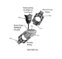
- FIG. 1 shows a high-level view of a fabrication machine 100, according to one embodiment.
- the fabrication machine 100 includes a primary manipulator 102, a secondary manipulator 104, and tool-heads 106.
- the primary manipulator 102 supports and positions an item 110 during fabrication.
- the primary manipulator 102 is a six-axis industrial robotic manipulator that handles the item 110 from seed item to mature product.
- the primary manipulator 102 positions the item 110 for manufacturing operations such as additive and subtractive manufacturing.
- the primary manipulator 102 orients the item 110 for interaction with the tool-heads 106, which provide additive and subtractive manufacturing mechanisms.
- the tool-heads 106 may include one or more of a Fused Deposition Modeling (FDM) print head, a milling head, and a robocasting extruder.
- FDM Fused Deposition Modeling
- additive and subtractive manufacturing techniques include 3D printing, milling, and drilling.
- a conductive material (or another material) may be added along a specified path instead of adding a wire.
- the tool-head 106 adds material from one direction (e.g., the z-axis), and the primary manipulator 102 and the secondary manipulator 104 move the item with respect to the tool-head 106, such that the surface of the item that is tooled, or that material is added to or removed from, is approximately orthogonal to the tool-head 106.
- the orientation of one or more of the tool-head 106 and the item 110 may differ.
- the secondary manipulator 104 may be used for component pick-and-place operations, as well as secondary manufacturing operations such as wire placement and hardware testing.
- the secondary manipulator 104 may pick components from Pick-and-Place reels and trays 112 and position the components with respect to the item 110 during fabrication.
- the components may be attached to the product 110, as described in greater detail with respect to Figures 7A-7B , 8A-8B , and 9A-9B .
- the fabrication machine 100 fuses additive and subtractive manufacturing with in-situ component placement to provide completely autonomous all-in-one product manufacturing.
- the fabrication machine 100 includes one or more sensors to measure parameters and characteristics of the item 110 while it is being manufactured.
- One or more of the sensors may be high precision sensors.
- the sensors may comprise one or more of a machine vision system, a sub-millimeter 2D machine vision system, and 3D machine vision system.
- the fabrication machine 100 may include a planar laser and camera system 114.
- the laser and camera system 114 generates precise measurements of the item 110 during fabrication.
- the laser and camera system 114 may be placed in a fixed geometry and the object of interest may be illuminated with the laser and photographed with the camera.
- the photograph of the laser line may be used to generate three dimensional data.
- the laser and camera system 114 can be used to generate a high-resolution 2D image as well as a high resolution 3D image.
- a laser and camera system is the SICK, Inc. Ranger.
- the sensor may include an infrared field and a camera. Information collected by a sensor may be used by the device to adjust subsequent steps in the manufacturing process.
- the system can correct or adjust the manufacturing process dynamically. For example, if, during an addition process, an excess of material was deposited, the sensor can detect and model the excess and adjust any subsequent step, whether an additive step or subtractive step, to account for this excess.
- subsequent fabrication steps may be adjusted to either apply less material during a subsequent addition process or to remove more material in a subsequent subtraction process.
- the sensors are used for in-situ monitoring of fabrication.
- the monitoring provides quality control by inspecting and tuning the additive and subtractive processes.
- the feedback from the various sensors allows the system to estimate product qualities, such as, for example, tolerances, dimensions, and mass. Tolerances may include temperature tolerances and stress tolerances.
- the fabrication machine 100 may include software to process the raw sensor data.
- Raw sensor data may be compared to an expected state of the fabrication process.
- future fabrication steps may be adjusted based on the sensor data.
- the resolution of the system is about 512x1396 pixels and depth information can be resolved to about 1/16th of a pixel. In other examples, the resolution may differ. Thus, a high accuracy sensor can resolve extremely small features.
- a sensor system is placed in a corner of the manufacturing space of the fabrication machine 100.
- the primary 102 and secondary 104 manipulators may pass components or items past the sensor system for scanning. Information about the scanned components or items may be used to adjust future fabrication steps and may be used for quality control.
- software registers the scan to a CAD model of the object at its current state of construction, and the scan is compared to the specification.
- the CAD model may be generated by a driver of the fabrication machine 100.
- the conformance of the scan to the specification can be quantified. This provides for detection of placement errors, alignment errors, deposit errors, and other types of non-conformities during construction.
- a machine vision system can identify pieces that differ from their specification and should be rejected or reworked. Comparisons to CAD models may be made using a 3D scan, though a 2D scan may also be used.
- non-conformities identified by the sensor system may be documented in a coordinate system that is registered to the object, and the fabrication machine 100 can adapt to correct any identified differences in future productions. According to one feature, this results in a tightly integrated in-process validation system, which is significantly more advanced than an assembly accept/reject check.
- sensor data from inspection during the manufacturing process may be archived and linked to an identifier (e.g., RFID tag or 3D barcode) embedded in a product. The sensor data may be used to uniquely identify the object later and may be used for analysis of the object, for example, for a failure analysis.
- the fabrication machine 100 may be used to manufacture a variety of products. It may be used to fabricate any products currently made using 3D printing process, and it may be used to fabricate a variety of electromechanical devices. Some exemplary products include MP3 players, radios, cell phones, personal digital assistants, tablet computers, toys such as toy cars or helicopters, including remote controlled vehicles, and small ground vehicles, such as surveillance ground vehicles.
- product fabrication by the fabrication machine 100 initiates with the selection of a seed item.
- the entire product is built on and around the seed item.
- the item 110 selected as the seed item is arbitrary.
- the seed item is defined by the assembly planning software.
- the seed item may be the battery, the motherboard, or any other item included in the cell phone.
- the assembly planning software for fabrication of the cell phone may specify that the seed item is the battery.
- the fabrication machine 100 may analyze an object and determine the assembly planning algorithm for fabricating identical items, as described in more detail with respect to Figure 3 .
- a seed-centric fabrication approach may be compared to the use of a build tray in 3D printing.
- the seed item can be an integral part of the end-product.
- the build tray is removed, for example by scraping the product from the tray.
- 3D-Printers Traditional three-dimensional additive manufacturing technologies are planar, generally employing three degrees of freedom (or three axes) X-Y-Z, and building up an object one layer at a time.
- a typical Fused Deposition Modeling (FDM) printer translates a build tray in the horizontal X-Y plane and as each layer is printed moves the tray downward (or the print head upward) along the Z-axis to begin a new layer.
- FDM Fused Deposition Modeling
- the object cannot be moved around any of the axes - the object cannot not be automatically rotated around the x-axis, the y-axis, or the z-axis during printing.
- Using just three axes imposes inherent limitations on how material is deposited and the overall complexity of the 3D-printed part because deposition of material is constrained to the current operating plane.
- Figure 2 shows planar surface printing (traditional 3D printing) 200.
- planar surface printing only allows for deposit of material by the tool-head 202 on to an item 208 at a position on the surface of a single plane 204.
- Traditional 3D printers use a simple X-Y platform 206 to support the item 208 for fabrication.
- 3D printers generally require a support material 210 in order to add material that overhangs or extends past the underlying surface on the previous plane of the item 208.
- Figure 3 shows non-planar surface printing 300, according to one embodiment.
- Non-planar surface printing 300 allows for arbitrary position and orientation of the item 304, which enables the machine to deposit material at any point on the surface of the item 304 from any direction.
- a manipulator such as the primary manipulator 102 shown in Figure 1 , can move the item along six different axes, allowing any surface of the item 304 to be positioned under the tool-head 302 for addition (or removal) of material.
- the fabrication machine 100 increases the number of fabricating axes to six or more axes, enabling the fabrication machine 100 to operate and deposit material and components in arbitrary planes and/or orientations.
- the fabricating axes include the x-axis, y-axis, and z-axis, as well as rotation around each of the x-axis, y-axis, and z-axis.
- the fabricator machine 100 utilizes a six-axis industrial robotic manipulator such as the primary manipulator 102 to provide the additional degrees of freedom.
- the fabrication machine 100 can manufacture products without using support materials, since the primary manipulator can position the item 304 in any selected orientation.
- the item 304 can be positioned at an angle or on its side such that the surface on which material is added is orthogonal with the tool-head.
- the tool-head adds material from the vertical z-axis and the item is positioned such that the surface to be tooled is approximately horizontal, orthogonal to the tool-head.
- objects can be printed without support materials in part because of the six or more axis positioning capability.
- the positioning capability in combination with the planning algorithms and the additive manufacturing processes together allow for a manufacturing process that does not require support materials yet can print objects having substantially any three-dimensional shape.
- the planning algorithms used for non-planar printing using, for example, the fabrication machine 100 may include two stages of planning: a first coarse planning stage and a second detailed planning stage.
- a Computer Automated Design (CAD) model of a product such as an electromechanical device, is mapped to assembly instructions in two stages.
- the first coarse planning stage may include decomposing the design into intermediate structures.
- the second detailed planning stage may include generating the sequence of instructions for achieving each intermediate structure.
- the planning algorithm may also include one or more of determining the exact placement of each component on the seed item or product, the order in which each component is placed on the item, how various components are secured, and where material is added, as well as how much material is added.
- a driver in the fabrication machine 100 produces an assembly plan for fabricating the end product.
- the assembly plan may be validated by a simulator, and may be used as an input to a product quality predictor.
- the product may be passed between the primary manipulator and the secondary manipulator during production, and it may be put down and picked up again.
- the fabrication machine 100 may be given a completed product design, and it may determine which components and materials will be needed to manufacture the product, how to print or fabricate various parts of the product, and how to assemble the product.
- a domain-specific planner is used to decompose a CAD model into intermediate parts.
- the domain-specific planner may determine an order for the assembly steps, and, in one example, it may schedule the execution of each assembly step.
- the planner may use a recursive decomposition motif, such as a Hierarchical Task Networks.
- the motif used by the planner reduces the planning search space by prescribing an acceptable sequence of high-level steps.
- the motifs may encode domain-specific heuristics in the form of composite process models.
- the planner may use one of three different motifs to create assembly instructions for fabrication of a router that includes a circuit board and a case.
- the first step is to build a case bottom, then place the circuit board on the case bottom, and then print over the board to complete the case enclosure.
- the first step is to build a case bottom, then place the circuit board on the case bottom, and then fuse a separately-built case top to the case bottom.
- the case is printed almost to completion, then the circuit board is placed in the case, and then the case is sealed.
- the motif used for a particular product may depend on the components in the product. For example, with respect to the example above, if the temperature of the printing material used to print the case is higher than the temperature the circuit board can withstand, then the first motif, which prints the case enclosure on top of the circuit board, would not be used.
- Decomposition motifs and information about various components, such as temperature constraints may be inputs to the planner.
- the planner operates on geometric shapes and includes an interface engine that can compute the intermediate assembly steps and satisfy manufacturing constraints such as printability and heat dissipation.
- the entire product is represented as a grid at multiple resolutions.
- the grid may be a three dimensional grid or a two dimensional grid.
- the grid may be used to determine how to decompose the product into multiple components or subtasks.
- the fabrication machine 100 determines what orientation the item 110 should be positioned in with respect to a tool-head 106 or the secondary manipulator 104 in order to complete each subtask. For example, the fabrication machine 100 may determine where and how in three-dimensions (in the x-y-z planes), and along the six axes of movement enabled by the primary manipulator 102, the item 110 should be positioned with respect to a tool-head 106 for adding material to create a certain shape, as specified in the grid.
- the fabrication machine 100 may include one or more processors, which may be used in manufacturing calculations.
- the fabrication machine 100 may also be used to print wires by depositing a conductive material along a wire path.
- wires maybe printed to connect two or more electrical components.
- a path planning algorithm may be used to determine the design path for printing wires.
- the product design may specify the wiring layout.
- the orientation of the product is determined before printing begins and remains constant until printing is complete.
- the fabrication machine 100 allows the orientation of an object to be changed during printing. Thus, after an initial product orientation is selected, successive positioning and orientation of the object can be selected to optimize fabrication.
- FIG 4 is a block diagram 400 showing components of the fabricator machine 100, according to one embodiment.
- the fabricator machine 100 takes as input a 3D design 402, such as a CAD model of an electromechanical design (with electrical components identified), and produces a uniquely identifiable physical product 404 that conforms to the input design.
- a driver 406 maps the design into executable instructions, predicts several properties of the product, and passes these instructions to the execution monitoring component 408.
- the driver 406 may decompose the 3D design into intermediate parts.
- the driver 406 may include a simulator to simulate product fabrication and test various parameters of the simulated product.
- the execution monitoring component 408 communicates with the fabricator 410.
- the instructions to fabricate and test (collect sensor data) are sent to the fabricator 410.
- the fabricator 410 includes sensors, and sends sensor data to the execution monitoring component 408.
- the fabricator 410 while the fabricator 410 fabricates the product, it communicates with the execution monitoring component 408, which monitors production.
- the output is a physical product 404, with an identifier (e.g., RFID tag or 3D barcode) that links the product 404 to the fabrication steps, the product quality estimates, and critical sensor data gathered during the fabrication process.
- an identifier e.g., RFID tag or 3D barcode
- the dashed arrows in Figure 4 show optional additional capabilities to support a continuous design and fabrication loop. For example, if an anomaly in the fabricated product 404 is detected by the execution monitoring component 408, the execution monitoring component 408 may communicate with the driver 406 to request updated design instructions. Similarly, the driver 406 may communicate with the design tool to request an updated design.
- the architecture of the fabrication machine 100 uses the output of a design tool and produces a uniquely identifiable product 404.
- the driver 406 generates an assembly plan and the fabricator 410 executes the plan, fabricating the designed object. Execution monitoring by one or more sensors provides real-time quality control.
- the driver 406 employs Artificial Intelligence (AI) planning techniques and heuristic search to map the 3D design into assembly steps using manufacturing motifs.
- the driver 406 determines the parts of the product, and determines the order of printing and assembly.
- a geometry formation component generates an executable fabricator plan, determining what material to deposit, from which angle, and with what thickness. Plans are processed to predict quality and may be verified and visualized in a simulator.
- the driver 406 may be implemented in software, it may be implemented in hardware, or it may include a combination of hardware and software components.
- the fabricator 410 integrates non-planar-printing with in-situ assembly.
- Non-planar printing is achieved by using a small seed component, held by the six-axis primary manipulator, as an additive manufacturing foundation.
- In-situ assembly places components such as circuit boards, motors, and batteries into the partially printed product.
- the execution monitoring component 408 interleaves fabrication and product inspection through collection and analysis of sensor data.
- the execution monitoring component 408 may use a sub-millimeter 2D computer vision system or a sub-millimeter 3D computer vision system.
- the execution monitoring component 408 may communicate with the driver 406, and the assembly plan may be adjusted to compensate.
- the execution monitoring component 408 may be implemented in software, it may be implemented in hardware, or it may include a combination of hardware and software components.
- the fabrication machine 100 may include a models and constraints component 412, which comprises the manufacturing constraints and motifs that are used in the software driver to produce valid assembly plans.
- the fabrication machine 100 may also include component libraries 414, which comprise collections of specifications and physical characteristics of components available for in-situ assembly.
- the library 414 may include specification and physical characteristics of components used in the electronics industry.
- Figure 5 is a flow chart of a fabrication method 500, according to one embodiment.
- an item is supported with a first manipulator.
- the first manipulator manipulates the item along at least one of six axes of movement to position the item with respect to a tool-head.
- a second manipulator manipulates a component, and orients the component at a predetermined orientation relative to the item.
- the component is attached to the item. In one example, the component is fitted to the item and attached. In another example, an adhesive is applied to at least one of the item and the component to secure the item and the component together.
- a tool-head is used to add material to at least one of the item and the component.
- the tool-head waits for the added material to dry before adding more material.
- the primary manipulator waits for the material to dry before repositioning the item. The time it takes for the material to dry may depend on the material and on the item. In some examples, it takes less than about one second or less than about half a second for the material to dry.
- the tool-head may be used to add material to at least one of the item and the component before the component is attached to the item at step 508. Additionally, a tool-head may be used to remove material from at least one of the item and the component.
- Figure 6 is a flow chart 600 of a part of a dynamic fabrication method, according to one embodiment.
- a tool-head is used to add material to an item or remove material from an item.
- the parameters of the item are measured.
- a sensor is used to measure the parameters of the item.
- the measured parameters are used to determine if subsequent steps will be adjusted. If no subsequent steps need to be adjusted, the method returns to step 602. If subsequent steps need to be adjusted based on the measured parameters, then the method proceeds to step 608, and subsequent steps are adjusted. In one example, the subsequent steps may be adjusted by a processor.
- the dynamic fabrication method may terminate, for example, when product fabrication is complete.
- the product is fabricated in situ, within the fabrication machine 100, using the initial item 110, the components, and various tool-heads 106.
- In situ fabrication of the entire product increases efficiency and decreases costs, for example by minimizing the use of human labor.
- Figures 7A-7B , 8A-8B , and 9A-9B show examples of several component placement operations, which may be configured as fabrication machine 100 settings.
- Pick-and-place assembly is widely used in the electronics industry for automated placement of components (integrated circuits, capacitors, resistors, etc.) on printed circuit boards.
- Traditional pick-and-place machines utilize a robotic manipulator to select a component from one of several component tape-and-reels or trays, translate to the product (a printed circuit board) and place the component on the product.
- Standardized interfaces and assembly procedures have been developed to accommodate a broad range of devices from a wide variety of device manufacturers.
- the fabrication machine 100 utilizes a pick-and-place manufacturing method with the added capability of operating in six degrees of freedom, allowing for the placement of components in arbitrary locations on the product assembly. To accommodate a wide range of components in a product assembly, several component placement and securing operations are possible.
- Figures 7A-7B show fabrication using two manipulators and a Synchronous Arm Setting 600, according to one embodiment.
- a primary manipulator 702 holds and positions an item 710.
- the secondary manipulator 704 holds a component 712.
- the secondary manipulator 704 synchronizes the position of the component 712 with the position of the item 710, and, as shown in Figure 7B , holds the component 712 firmly in place on the item 710.
- the secondary manipulator 704 performs the position synchronization and component 712 placement operations regardless of the orientation of the item 710.
- One or more additive manufacturing tool-heads 706 adds material to at least one of the item 710 and the component 712 to build a support structure on and/or around the component 712 and securely lock the component 712 in place on the item 710.
- the component placement operation shown in Figures 7A and 7B may be used for operations that involve larger and/or complex components.
- Figures 8A-8B show fabrication using two manipulators and a Support Structure Setting 700, according to one embodiment.
- a support structures 808a, 808b are added to the item 810 before the component 812 is placed on the item 810.
- the primary manipulator 802 holds the item 810 in place while the tool-head 806 adds material to the item 810, building the support structures 808a, 808b.
- the support structures 808a, 808b are configured to hold the component 812 in place on the item 810 using a friction constraint.
- the secondary manipulator 804 places the component 812 on the item 810, in the position created by the support structures 808a, 808b, as shown in Figure 8B .
- the component 812 may be firmly held in place on the item 810 by friction, and may be embedded on the item 810 with additional material deposits.
- the support structures 808a, 808b form a single, connected support structure, and the illustration in Figures 8A and 8B shows a cross-section of the support structure.
- Figures 9A-9B show the use of an adhesive 914 during fabrication to secure the component 912 to the item 910, according to one embodiment.
- the primary manipulator 902 positions the item 910 with respect to the tool-head 906 for application of the adhesive 914 to the surface of the item 910 on which the component 912 is to be attached.
- the primary manipulator 902 may move the item 910 for even application of the adhesive 914 to the surface area.
- the secondary manipulator 904 places the component 912 on the item 910.
- the adhesive 914 holds the component 912 firmly in place on the item 910, and additional material deposits may be used to embed the component 912 on the item 910.
- components that may be added to an item include processors, motherboards, batteries, displays, memory drives, wires, buttons, and user interfaces.
- the components may be pre-manufactured, and then secured to the item or product.
- one or more tool-heads may be used to add various pre-selected materials to the item to create the components directly on the item. For example, instead of placing a wire on an item, a tool-head may be used to add a line of conductive material.
- insulating materials may be added to the item.
- any type of material may be added to the item during fabrication.
- the materials may include, for example, one or more of thermoplastics, urethanes, urethane rubbers, silicones, ceramics, stainless steel, aluminum, and titanium.
- the fabrication machine 100 includes one or more tool-heads 106. According to one embodiment, a sufficient number of tool-heads 106 may be included in the fabrication machine 100 such that all tooling of the item 110 occurs within the workspace of the primary manipulator 102 of the fabrication machine 100. Many of the fabrication methods of the fabrication machine 100 generally involve the use of additive manufacturing technologies. According to one feature, the fabrication system 100 can support several additive manufacturing technologies.
- FDM Fused Deposition Modeling
- LENS Laser Engineered Net Shaping
- Milling/drilling machines selective laser sintering, stereolithography, laminated object manufacturing, and electron beam melting.
- FDM is a process in which thermoplastics are liquefied and deposited via an extrusion nozzle.
- Robocasting may be similar in methodology to FDM.
- robocasting uses a syringe-like nozzle to dispense non-molten semi-liquid materials, such as urethanes, silicone, or ceramics.
- the material either cures using additional operations (such as UV or heat) or is dispensed during the curing stage (for example, 2 part silicone or urethane rubber).
- additional materials are deposited at high resolution.
- the materials may include, for example, one or more of stainless steel, aluminum, and titanium.
- milling/drilling machines having five or more axes of movement may be used for additive or subtractive manufacturing.
- selective laser sintering uses one or more high power lasers to fuse small particles of plastic or metal together, and may be used to create parts out of, for example, ceramic or titanium.
- stereolithography uses a light curing resin and a low power laser to create a resin based part.
- laminated object manufacturing uses layers of paper and a cutting laser.
- electron beam melting uses an electron beam and metal powder to create a part by fusing the thin layers of melted metal powder together.
- Subtractive manufacturing or machining may be used to remove material from a product.
- drilling tool-heads provide precision holes
- tapping tool-heads provide threading for fasteners
- milling tool-heads provide high precision surface finish.
- the use of subtractive manufacturing in conjunction with additive manufacturing increases the types of artifacts that can be fabricated. Additionally, subtractive manufacturing can be used to add fasteners.
- fasteners can be eliminated by using the fabrication machine 100, fasteners may be useful for component replacement or servicing by the end user (for example, a battery hatch).
- a specialized manipulator may be used to handle the selection and insertion of a wide range of fasteners into threaded holes created by subtractive manufacturing.
- the fabrication machine 100 is used to add wires or cables to a product, and the fabrication machine 100 includes sensors for detecting electrical anomalies in wiring or printed wires. Sensors may also be used to analyze the conductivity of wires or cables.
- the fabrication machine 100 may include tool-heads designed to prepare and cut wires or cables.
- the fabrication machine 100 may be used in a Manufacturing Distribution Facility, and it may use the product of the facility as components in the final product.
- a facility may manufacture net shape metal parts or circuit boards, which may be input components for products fabricated with the fabrication machine 100.
- the fabrication machine 100 may be used by individuals to create new products that overcome limitations of existing products.
- the fabrication machine 100 may be used by the military in the field.
- a soldier in the field may use the fabrication machine 100 to modify a surveillance robot.
- the surveillance robot is unable to climb over obstacles in the field, the soldier may use the fabrication machine 100 to create and fabricate a new design.
- an offsite military personnel may redesign the surveillance robot and transmit the new design to the soldier in the field.
- the soldier could use the fabrication machine 100 to easily fabricate a new surveillance machine with minimal product fabrication knowledge.
- the fabrication machine 100 improves manufacturing capabilities and innovation by increasing access to 3D printing while also reducing costs and required production skills.
- the fabrication machine 100 may be used to repair a product.
- the manipulators may position the product such that the sensor system can scan the product and determine the product identifier (for example, an RFID, or 3D barcode).
- the product identifies may be used to obtain the original design and parameters of the design.
- the fabrication machine 100 can compare the current state of the design with the intended final state, and create a fabrication plan using the existing structure as the seed. For instance, if a toy helicopter had a damaged tail, the tail may be removed and the fabrication system 100 can recognize the design, determine what is missing, and re-fabricate the tail. Note that the damaged tail may be removed by the fabrication machine 100 using subtractive processing or it may be manually removed. In one embodiment, the fabrication machine 100 may be used to remove damaged or obsolete design elements autonomously.
Abstract
Description
- A portion of typical three-dimensional printing manufacturing processes are currently automated. However, most products are not manufactured by fully automated means. Human intervention and labor is almost always required. In traditional 3D printing, designs must still be divided into parts for production, and a trained individual assembles the fabricated parts into the final product after printing. A traditional 3D printing technology is discussed, for example, in
U.S. Patent No. 7,939,003 . In traditional 3D printing, a product is printed by depositing material on an item placed on a horizontal platform. Material is deposited layer by layer, building the part up from a base layer. An orientation for the object to be printed is determined before printing starts, and the orientation of the object remains constant until printing is completed - the orientation is not changed during fabrication. Traditional 3D printing creates an object from a base layer, moving upward, and does not allow material to be subsequently added to a previous layer or on a side of the object. - Additionally, in traditional 3D printing, material can only be deposited in areas in which there is already a base on which to deposit material. If the product to be printed requires an overhang, or becomes larger on a subsequent layer, a support structure is used to support the material that extends past the base on the previous plane. The support structure is removed after printing is complete, requiring extra processing and human involvement in the manufacturing steps. Human involvement in manufacturing steps increases production costs and creates increased factory safety risks. The cost of the support material also increases production costs.
- Furthermore, in traditional 3D printing, connectors and fasteners are used to secure product components together, and seams are created when product components are fused together. Connectors, fasteners, seams, and similar interfaces are frequently a source of failure in the end product. A fabrication device that reduces the number of connectors, fasteners, seams, and similar component interfaces increases the quality of the end product and reduces product failure. Traditional 3D printers require significant effort to produce a product design, and may require human intervention to assemble a finished product. A device that can fabricate a finished product from a design without any expert help or intervention increases both efficiency and product production possibilities.
- The systems and methods described herein decrease manufacturing costs, improve product quality, and improve factory safety by reducing the need for human labor during manufacture and more fully automating the manufacture and assembly processes.
- The systems and methods described herein include a fabrication machine/method that fuses additive and subtractive manufacturing with in-situ component placement to provide completely autonomous all-in-one product manufacturing. Product fabrication is centered around a six-axis industrial robotic manipulator (primary manipulator) that handles the product from seed component to mature product. The primary manipulator positions the product for manufacturing operations such as additive and subtractive manufacturing (3D printing, milling and drilling). A secondary manipulator handles component pick-and-place and secondary manufacturing operations such as wire placement and hardware testing. According to one feature, all-in-one product manufacturing increases the ability to produce prototypes or small production runs of devices, since no human intervention is used, product design is simpler and production is more efficient.
- Optionally, the systems and methods described herein include sensors, typically high precision sensors, that can measure parameters and characteristics of the device being manufactured while the process is taking place. For example, in one embodiment, the system includes a precision scanning device that will generate precise measurements of the device being fabricated. In another embodiment, the system includes a laser and camera sensor system. Information collected by the sensor may be used by the device to adjust subsequent steps in the manufacturing process. According to one feature, in-situ monitoring provides quality control by inspecting and tuning the additive and subtractive processes. The feedback from the sensors allows the system to estimate product qualities, such as, for example, tolerances, dimensions, and mass.
- According to one aspect, a fabrication system includes a tool-head for manufacturing, a first manipulator, and a second manipulator. The first manipulator supports and manipulates an item, and is configured to provide six-axes of movement for positioning of the item relative the tool-head. The second manipulator carries a component and orients the component at a select orientation relative to the item supported on the first manipulator. The tool-head is configured to add material to at least one of the item and the component. The first and second manipulators provide at least six axes of fabrication for the tool-head.
- According to one embodiment, the tool-head is configured to remove material from at least one of the item and the component. In another embodiment, the tool-head is configured to add an adhesive material to at least one of the item and the component. The adhesive material is configured to secure the component to the item. In a further embodiment, the tool-head includes at least one of a fused deposition modeling print head, a milling head, and a robocasting extruder.
- According to another embodiment, the fabrication system includes a sensor configured to measure parameters of the item during manufacturing. The sensor may be a high precision sensor. In one example, the sensor includes a laser and camera system configured to generate measurements of the item. In one embodiment, fabrication system includes a processor configured to adjust manufacturing processes in response to the measured parameters. According to another embodiment, the fabrication system includes a processor configured to determine how to move at least one of the first manipulator and the second manipulator. In a further embodiment, the processor is configured to use a hierarchical task network to determine how to manufacture a product using the first manipulator, the second manipulator, and the tool-head. According to one embodiment, the item includes hardware, and the second manipulator is configured to test the hardware.
- In one embodiment, the fabrication system includes a software component configured to use a three dimensional model of an end-product to generate a sequence of instructions for movements of at least one of the first manipulator, the second manipulator, and the tool-head. The sequence of instructions may instruct one or more of the first manipulator, the second manipulator, and the tool-head to move in a manner to fabricate the product. In one embodiment, the fabrication system also includes a simulator configured to validate the sequence of instructions.
- In another embodiment, the item is a previously printed object that is not in its original form, and the fabrication system includes a software component configured to use a three dimensional model of the item and a three dimensional model of the original form of the previously printed object to generate a sequence of instructions for movements of at least one of the first manipulator, the second manipulator, and the tool-head to return the previously printed object to its original form. According to one example, the fabrication machine may be used to repair a previously printed object that has been damaged.
- According to another aspect, a fabrication method includes supporting an item with a first manipulator, manipulating the item, using the first manipulator, along at least one of six axes of movement, to position the item with respect to a tool-head, manipulating a component, using a second manipulator, and orienting the component at a predetermined orientation relative to the item, attaching the component to the item, and adding material to at least one of the item and the component with the tool-head. The first and second manipulators provide at least six axes of fabrication for the tool-head.
- According to one embodiment, the method includes removing material from at least one of the item and the component with the tool-head. In another embodiment, the method includes adding an adhesive material, using the tool-head, to at least one of the item and the component, and securing the component to the item. In a further embodiment, the method includes adding a wire to the item. The wire may be added by placing the wire using the second manipulator, or the wire may be added by adding material to the item using the tool-head to create the wire. In one embodiment, the item includes hardware, and the method includes testing the hardware.
- According to another embodiment, the fabrication method further includes measuring parameters of the item during fabrication. According to one embodiment, the method includes adjusting, based on the measured parameters, at least one of manipulating the item, manipulating the component, and adding material. In a further embodiment, measuring parameters includes capturing images of the item during fabrication.
- In one embodiment, the fabrication method further includes determining how to move at least one of the first manipulator and the second manipulator based at least in part on a finished product design. In one example, determining how to move at least one of the first manipulator and the second manipulator includes using a hierarchical task network to determine how to manufacture a product using the first manipulator, the second manipulator, and the tool-head.
- In another embodiment, the fabrication method further includes receiving a three dimensional model of a product, and generating a sequence of instructions for moving at least one of the first manipulator, the second manipulator, and the tool-head to fabricate the product. The fabrication method may also include decomposing the three-dimensional model into a plurality of intermediate parts, and generating the sequence of instructions may include generating an intermediate sequence of instructions for each intermediate part. In one embodiment, the fabrication method includes validating the sequence of instructions with a simulator. In another embodiment, generating a sequence of instructions includes determining at least one parameter of at least one part of the product, and generating instructions for production that do not damage the at least one part of the product.
- According to one embodiment, the item is a previously printed object that is not in its original form, and the fabrication method further includes generating a three-dimensional model of the item, receiving a three dimensional model of the original form of the previously printed object, and generating a sequence of instructions for moving at least one of the first manipulator, the second manipulator, and the tool-head to return the previously printed object to its original form. In one example, the fabrication method is used to repair a previously printed object that has been damaged.
- The following figures depict certain illustrative embodiments of the present disclosure in which like reference numerals refer to like elements. These depicted embodiments may not be drawn to scale and are to be understood as illustrative of the present disclosure and as not limiting in any way.
-
Figure 1 shows a fabrication machine, according to an embodiment of the invention; -
Figure 2 shows prior art 3D planar surface printing; -
Figure 3 shows non-planar surface printing, according to an embodiment of the invention; -
Figure 4 is a block diagram showing components of the fabricator machine, according to an embodiment of the invention; -
Figure 5 is a flow chart of a fabrication method, according to an embodiment of the invention; -
Figure 6 is a flow chart of a dynamic fabrication method, according to an embodiment of the invention; -
Figures 7A-7B show fabrication using two manipulators, according to an embodiment of the invention; -
Figure 8A-8B show fabrication using two manipulators, according to an embodiment of the invention; and -
Figures 9A-9B show fabrication with the use of an adhesive, according to an embodiment of the invention. - Systems and methods are provided to more fully automate manufacturing and assembly processes, thereby reducing human labor. In one example, a fabrication machine includes a six-axis industrial robotic manipulator and fuses additive and subtractive manufacturing with in-situ component placement to provide completely autonomous all-in-one product manufacturing. The six-axis robotic manipulator (the primary manipulator) positions an item for manufacturing operations (for example, 3D printing, milling and drilling). A secondary manipulator handles component pick-and-place and secondary manufacturing operations such as wire placement and hardware testing. The system may include one or more sensors that can measure parameters and characteristics of the product being manufactured while the process is taking place. For example, in one embodiment, the system includes a precision visual scanning device that will generate precise measurements of the product being fabricated. Information collected by the sensor may be used by the fabrication machine to adjust subsequent steps in the manufacturing process.
-
Figure 1 shows a high-level view of afabrication machine 100, according to one embodiment. Thefabrication machine 100 includes aprimary manipulator 102, asecondary manipulator 104, and tool-heads 106. Theprimary manipulator 102 supports and positions anitem 110 during fabrication. Theprimary manipulator 102 is a six-axis industrial robotic manipulator that handles theitem 110 from seed item to mature product. Theprimary manipulator 102 positions theitem 110 for manufacturing operations such as additive and subtractive manufacturing. In particular, theprimary manipulator 102 orients theitem 110 for interaction with the tool-heads 106, which provide additive and subtractive manufacturing mechanisms. The tool-heads 106 may include one or more of a Fused Deposition Modeling (FDM) print head, a milling head, and a robocasting extruder. According to various examples, additive and subtractive manufacturing techniques include 3D printing, milling, and drilling. In one example, a conductive material (or another material) may be added along a specified path instead of adding a wire. - The six axes of manipulation of the
item 110 provided by theprimary manipulator 102 result in non-planar material deposit paths, and allow for fabrication without the use of a support material, as described in more detail with respect toFigure 3 . In one embodiment, the tool-head 106 adds material from one direction (e.g., the z-axis), and theprimary manipulator 102 and thesecondary manipulator 104 move the item with respect to the tool-head 106, such that the surface of the item that is tooled, or that material is added to or removed from, is approximately orthogonal to the tool-head 106. For example, if the tool-head adds material on top of the item, vertically along the z-axis, the surface to be tooled is positioned in the horizontal x-y plane. In other embodiments, the orientation of one or more of the tool-head 106 and theitem 110 may differ. - The
secondary manipulator 104 may be used for component pick-and-place operations, as well as secondary manufacturing operations such as wire placement and hardware testing. Thesecondary manipulator 104 may pick components from Pick-and-Place reels andtrays 112 and position the components with respect to theitem 110 during fabrication. The components may be attached to theproduct 110, as described in greater detail with respect toFigures 7A-7B ,8A-8B , and9A-9B . According to one feature, thefabrication machine 100 fuses additive and subtractive manufacturing with in-situ component placement to provide completely autonomous all-in-one product manufacturing. - According to one embodiment, the
fabrication machine 100 includes one or more sensors to measure parameters and characteristics of theitem 110 while it is being manufactured. One or more of the sensors may be high precision sensors. The sensors may comprise one or more of a machine vision system, a sub-millimeter 2D machine vision system, and 3D machine vision system. In one example, as shown inFigure 1 , thefabrication machine 100 may include a planar laser andcamera system 114. The laser andcamera system 114 generates precise measurements of theitem 110 during fabrication. The laser andcamera system 114 may be placed in a fixed geometry and the object of interest may be illuminated with the laser and photographed with the camera. The photograph of the laser line may be used to generate three dimensional data. By moving the object through the laser-line plane while generating images, a 3D image of the product can be generated. The laser andcamera system 114 can be used to generate a high-resolution 2D image as well as a high resolution 3D image. One example of a laser and camera system is the SICK, Inc. Ranger. In another embodiment, the sensor may include an infrared field and a camera. Information collected by a sensor may be used by the device to adjust subsequent steps in the manufacturing process. Thus, the system can correct or adjust the manufacturing process dynamically. For example, if, during an addition process, an excess of material was deposited, the sensor can detect and model the excess and adjust any subsequent step, whether an additive step or subtractive step, to account for this excess. In particular, subsequent fabrication steps may be adjusted to either apply less material during a subsequent addition process or to remove more material in a subsequent subtraction process. - According to one embodiment, the sensors are used for in-situ monitoring of fabrication. The monitoring provides quality control by inspecting and tuning the additive and subtractive processes. The feedback from the various sensors allows the system to estimate product qualities, such as, for example, tolerances, dimensions, and mass. Tolerances may include temperature tolerances and stress tolerances.
- The
fabrication machine 100 may include software to process the raw sensor data. Raw sensor data may be compared to an expected state of the fabrication process. According to one embodiment, future fabrication steps may be adjusted based on the sensor data. - In one example, the resolution of the system is about 512x1396 pixels and depth information can be resolved to about 1/16th of a pixel. In other examples, the resolution may differ. Thus, a high accuracy sensor can resolve extremely small features. In one embodiment, a sensor system is placed in a corner of the manufacturing space of the
fabrication machine 100. The primary 102 and secondary 104 manipulators may pass components or items past the sensor system for scanning. Information about the scanned components or items may be used to adjust future fabrication steps and may be used for quality control. In one example, software registers the scan to a CAD model of the object at its current state of construction, and the scan is compared to the specification. The CAD model may be generated by a driver of thefabrication machine 100. By comparing the scan to the specification, the conformance of the scan to the specification can be quantified. This provides for detection of placement errors, alignment errors, deposit errors, and other types of non-conformities during construction. In one example, a machine vision system can identify pieces that differ from their specification and should be rejected or reworked. Comparisons to CAD models may be made using a 3D scan, though a 2D scan may also be used. - In one embodiment, non-conformities identified by the sensor system may be documented in a coordinate system that is registered to the object, and the
fabrication machine 100 can adapt to correct any identified differences in future productions. According to one feature, this results in a tightly integrated in-process validation system, which is significantly more advanced than an assembly accept/reject check. In one embodiment, sensor data from inspection during the manufacturing process may be archived and linked to an identifier (e.g., RFID tag or 3D barcode) embedded in a product. The sensor data may be used to uniquely identify the object later and may be used for analysis of the object, for example, for a failure analysis. - According to various embodiments, the
fabrication machine 100 may be used to manufacture a variety of products. It may be used to fabricate any products currently made using 3D printing process, and it may be used to fabricate a variety of electromechanical devices. Some exemplary products include MP3 players, radios, cell phones, personal digital assistants, tablet computers, toys such as toy cars or helicopters, including remote controlled vehicles, and small ground vehicles, such as surveillance ground vehicles. - According to one embodiment, product fabrication by the
fabrication machine 100 initiates with the selection of a seed item. The entire product is built on and around the seed item. Theitem 110 selected as the seed item is arbitrary. In one embodiment, the seed item is defined by the assembly planning software. For example, for fabrication of a cell phone, the seed item may be the battery, the motherboard, or any other item included in the cell phone. In one example, the assembly planning software for fabrication of the cell phone may specify that the seed item is the battery. In one embodiment, thefabrication machine 100 may analyze an object and determine the assembly planning algorithm for fabricating identical items, as described in more detail with respect toFigure 3 . - A seed-centric fabrication approach may be compared to the use of a build tray in 3D printing. However, in seed-centric fabrication, such as by the
fabrication machine 100, the seed item can be an integral part of the end-product. In 3D printing, the build tray is removed, for example by scraping the product from the tray. - Traditional three-dimensional additive manufacturing technologies (3D-Printers) are planar, generally employing three degrees of freedom (or three axes) X-Y-Z, and building up an object one layer at a time. For example, a typical Fused Deposition Modeling (FDM) printer translates a build tray in the horizontal X-Y plane and as each layer is printed moves the tray downward (or the print head upward) along the Z-axis to begin a new layer. In particular, with traditional 3D-Printers, the object cannot be moved around any of the axes - the object cannot not be automatically rotated around the x-axis, the y-axis, or the z-axis during printing. Using just three axes imposes inherent limitations on how material is deposited and the overall complexity of the 3D-printed part because deposition of material is constrained to the current operating plane.
-
Figure 2 shows planar surface printing (traditional 3D printing) 200. As shown inFigure 2 , planar surface printing only allows for deposit of material by the tool-head 202 on to anitem 208 at a position on the surface of asingle plane 204. Traditional 3D printers use asimple X-Y platform 206 to support theitem 208 for fabrication. Additionally, 3D printers generally require asupport material 210 in order to add material that overhangs or extends past the underlying surface on the previous plane of theitem 208. -
Figure 3 showsnon-planar surface printing 300, according to one embodiment.Non-planar surface printing 300 allows for arbitrary position and orientation of theitem 304, which enables the machine to deposit material at any point on the surface of theitem 304 from any direction. A manipulator, such as theprimary manipulator 102 shown inFigure 1 , can move the item along six different axes, allowing any surface of theitem 304 to be positioned under the tool-head 302 for addition (or removal) of material. Thefabrication machine 100 increases the number of fabricating axes to six or more axes, enabling thefabrication machine 100 to operate and deposit material and components in arbitrary planes and/or orientations. As shown inFigure 3 , the fabricating axes include the x-axis, y-axis, and z-axis, as well as rotation around each of the x-axis, y-axis, and z-axis. Rather than utilizing a simple X-Y platform, thefabricator machine 100 utilizes a six-axis industrial robotic manipulator such as theprimary manipulator 102 to provide the additional degrees of freedom. - According to one feature, the
fabrication machine 100 can manufacture products without using support materials, since the primary manipulator can position theitem 304 in any selected orientation. Thus, theitem 304 can be positioned at an angle or on its side such that the surface on which material is added is orthogonal with the tool-head. In general, according to an example, the tool-head adds material from the vertical z-axis and the item is positioned such that the surface to be tooled is approximately horizontal, orthogonal to the tool-head. Thus, objects can be printed without support materials in part because of the six or more axis positioning capability. The positioning capability in combination with the planning algorithms and the additive manufacturing processes together allow for a manufacturing process that does not require support materials yet can print objects having substantially any three-dimensional shape. This is in contrast to traditional 3D printing technologies, which require support material to handle overhangs in three-dimensional geometries, as described above with respect toFigure 2 . Eliminating the use of support materials increases efficiency and safety, since using support material requires post-processing of the printed part to remove the supports. The supports are removed either manually, or with a hazardous chemical bath that dissolves the support material. Manual removal of the support is time consuming, while the chemical baths are hazardous. Thus, the use of thefabrication machine 100 for product manufacturing increases manufacturing efficiency and safety. - The planning algorithms used for non-planar printing using, for example, the
fabrication machine 100, may include two stages of planning: a first coarse planning stage and a second detailed planning stage. In one example, a Computer Automated Design (CAD) model of a product, such as an electromechanical device, is mapped to assembly instructions in two stages. The first coarse planning stage may include decomposing the design into intermediate structures. The second detailed planning stage may include generating the sequence of instructions for achieving each intermediate structure. The planning algorithm may also include one or more of determining the exact placement of each component on the seed item or product, the order in which each component is placed on the item, how various components are secured, and where material is added, as well as how much material is added. In one embodiment, a driver in thefabrication machine 100 produces an assembly plan for fabricating the end product. The assembly plan may be validated by a simulator, and may be used as an input to a product quality predictor. The product may be passed between the primary manipulator and the secondary manipulator during production, and it may be put down and picked up again. - According to one embodiment, the
fabrication machine 100 may be given a completed product design, and it may determine which components and materials will be needed to manufacture the product, how to print or fabricate various parts of the product, and how to assemble the product. In one example, a domain-specific planner is used to decompose a CAD model into intermediate parts. The domain-specific planner may determine an order for the assembly steps, and, in one example, it may schedule the execution of each assembly step. The planner may use a recursive decomposition motif, such as a Hierarchical Task Networks. According to one feature, the motif used by the planner reduces the planning search space by prescribing an acceptable sequence of high-level steps. The motifs may encode domain-specific heuristics in the form of composite process models. - In one example, the planner may use one of three different motifs to create assembly instructions for fabrication of a router that includes a circuit board and a case. In a first motif, the first step is to build a case bottom, then place the circuit board on the case bottom, and then print over the board to complete the case enclosure. In a second motif, the first step is to build a case bottom, then place the circuit board on the case bottom, and then fuse a separately-built case top to the case bottom. In a third motif, the case is printed almost to completion, then the circuit board is placed in the case, and then the case is sealed.
- The motif used for a particular product may depend on the components in the product. For example, with respect to the example above, if the temperature of the printing material used to print the case is higher than the temperature the circuit board can withstand, then the first motif, which prints the case enclosure on top of the circuit board, would not be used. Decomposition motifs and information about various components, such as temperature constraints, may be inputs to the planner. According to one embodiment, the planner operates on geometric shapes and includes an interface engine that can compute the intermediate assembly steps and satisfy manufacturing constraints such as printability and heat dissipation.
- In one example, the entire product is represented as a grid at multiple resolutions. The grid may be a three dimensional grid or a two dimensional grid. The grid may be used to determine how to decompose the product into multiple components or subtasks. Once the components or subtasks are identified, the
fabrication machine 100 determines what orientation theitem 110 should be positioned in with respect to a tool-head 106 or thesecondary manipulator 104 in order to complete each subtask. For example, thefabrication machine 100 may determine where and how in three-dimensions (in the x-y-z planes), and along the six axes of movement enabled by theprimary manipulator 102, theitem 110 should be positioned with respect to a tool-head 106 for adding material to create a certain shape, as specified in the grid. Thefabrication machine 100 may include one or more processors, which may be used in manufacturing calculations. - The
fabrication machine 100 may also be used to print wires by depositing a conductive material along a wire path. In particular, wires maybe printed to connect two or more electrical components. In one embodiment, a path planning algorithm may be used to determine the design path for printing wires. In another embodiment, the product design may specify the wiring layout. In traditional 3D printers, the orientation of the product is determined before printing begins and remains constant until printing is complete. In contrast, thefabrication machine 100 allows the orientation of an object to be changed during printing. Thus, after an initial product orientation is selected, successive positioning and orientation of the object can be selected to optimize fabrication. -
Figure 4 is a block diagram 400 showing components of thefabricator machine 100, according to one embodiment. As shown inFigure 4 , thefabricator machine 100 takes as input a3D design 402, such as a CAD model of an electromechanical design (with electrical components identified), and produces a uniquely identifiablephysical product 404 that conforms to the input design. Adriver 406 maps the design into executable instructions, predicts several properties of the product, and passes these instructions to theexecution monitoring component 408. Thedriver 406 may decompose the 3D design into intermediate parts. Thedriver 406 may include a simulator to simulate product fabrication and test various parameters of the simulated product. - The
execution monitoring component 408 communicates with thefabricator 410. The instructions to fabricate and test (collect sensor data) are sent to thefabricator 410. Thefabricator 410 includes sensors, and sends sensor data to theexecution monitoring component 408. Thus, in one embodiment, while thefabricator 410 fabricates the product, it communicates with theexecution monitoring component 408, which monitors production. The output is aphysical product 404, with an identifier (e.g., RFID tag or 3D barcode) that links theproduct 404 to the fabrication steps, the product quality estimates, and critical sensor data gathered during the fabrication process. - The dashed arrows in
Figure 4 show optional additional capabilities to support a continuous design and fabrication loop. For example, if an anomaly in the fabricatedproduct 404 is detected by theexecution monitoring component 408, theexecution monitoring component 408 may communicate with thedriver 406 to request updated design instructions. Similarly, thedriver 406 may communicate with the design tool to request an updated design. - As shown in
Figure 4 , the architecture of thefabrication machine 100 uses the output of a design tool and produces a uniquelyidentifiable product 404. Thedriver 406 generates an assembly plan and thefabricator 410 executes the plan, fabricating the designed object. Execution monitoring by one or more sensors provides real-time quality control. - According to one embodiment, the
driver 406 employs Artificial Intelligence (AI) planning techniques and heuristic search to map the 3D design into assembly steps using manufacturing motifs. Thedriver 406 determines the parts of the product, and determines the order of printing and assembly. A geometry formation component generates an executable fabricator plan, determining what material to deposit, from which angle, and with what thickness. Plans are processed to predict quality and may be verified and visualized in a simulator. According to various embodiments, thedriver 406 may be implemented in software, it may be implemented in hardware, or it may include a combination of hardware and software components. - In one embodiment, the
fabricator 410 integrates non-planar-printing with in-situ assembly. Non-planar printing is achieved by using a small seed component, held by the six-axis primary manipulator, as an additive manufacturing foundation. In-situ assembly places components such as circuit boards, motors, and batteries into the partially printed product. - According to another embodiment, the
execution monitoring component 408 interleaves fabrication and product inspection through collection and analysis of sensor data. Theexecution monitoring component 408 may use a sub-millimeter 2D computer vision system or a sub-millimeter 3D computer vision system. According to one feature, if sensor data analysis indicates a fabrication anomaly, theexecution monitoring component 408 may communicate with thedriver 406, and the assembly plan may be adjusted to compensate. According to various embodiments, theexecution monitoring component 408 may be implemented in software, it may be implemented in hardware, or it may include a combination of hardware and software components. - As shown in the block diagram 400, the
fabrication machine 100 may include a models andconstraints component 412, which comprises the manufacturing constraints and motifs that are used in the software driver to produce valid assembly plans. Thefabrication machine 100 may also includecomponent libraries 414, which comprise collections of specifications and physical characteristics of components available for in-situ assembly. In one example, thelibrary 414 may include specification and physical characteristics of components used in the electronics industry. -
Figure 5 is a flow chart of afabrication method 500, according to one embodiment. At step 502, an item is supported with a first manipulator. Atstep 504, the first manipulator manipulates the item along at least one of six axes of movement to position the item with respect to a tool-head. Atstep 506, a second manipulator manipulates a component, and orients the component at a predetermined orientation relative to the item. Atstep 508, the component is attached to the item. In one example, the component is fitted to the item and attached. In another example, an adhesive is applied to at least one of the item and the component to secure the item and the component together. Atstep 510, a tool-head is used to add material to at least one of the item and the component. In one example, the tool-head waits for the added material to dry before adding more material. In another example, the primary manipulator waits for the material to dry before repositioning the item. The time it takes for the material to dry may depend on the material and on the item. In some examples, it takes less than about one second or less than about half a second for the material to dry. In other embodiments, the tool-head may be used to add material to at least one of the item and the component before the component is attached to the item atstep 508. Additionally, a tool-head may be used to remove material from at least one of the item and the component. -
Figure 6 is aflow chart 600 of a part of a dynamic fabrication method, according to one embodiment. Atstep 602, a tool-head is used to add material to an item or remove material from an item. Atstep 604, the parameters of the item are measured. In one example, a sensor is used to measure the parameters of the item. Atstep 606, the measured parameters are used to determine if subsequent steps will be adjusted. If no subsequent steps need to be adjusted, the method returns to step 602. If subsequent steps need to be adjusted based on the measured parameters, then the method proceeds to step 608, and subsequent steps are adjusted. In one example, the subsequent steps may be adjusted by a processor. The dynamic fabrication method may terminate, for example, when product fabrication is complete. - According to one embodiment, and as described above, the product is fabricated in situ, within the
fabrication machine 100, using theinitial item 110, the components, and various tool-heads 106. In situ fabrication of the entire product increases efficiency and decreases costs, for example by minimizing the use of human labor.Figures 7A-7B ,8A-8B , and9A-9B show examples of several component placement operations, which may be configured asfabrication machine 100 settings. - Pick-and-place assembly is widely used in the electronics industry for automated placement of components (integrated circuits, capacitors, resistors, etc.) on printed circuit boards. Traditional pick-and-place machines utilize a robotic manipulator to select a component from one of several component tape-and-reels or trays, translate to the product (a printed circuit board) and place the component on the product. Standardized interfaces and assembly procedures have been developed to accommodate a broad range of devices from a wide variety of device manufacturers.
- As described above, the
fabrication machine 100 utilizes a pick-and-place manufacturing method with the added capability of operating in six degrees of freedom, allowing for the placement of components in arbitrary locations on the product assembly. To accommodate a wide range of components in a product assembly, several component placement and securing operations are possible. -
Figures 7A-7B show fabrication using two manipulators and aSynchronous Arm Setting 600, according to one embodiment. As shown inFigure 7A , aprimary manipulator 702 holds and positions anitem 710. Thesecondary manipulator 704 holds acomponent 712. Thesecondary manipulator 704 synchronizes the position of thecomponent 712 with the position of theitem 710, and, as shown inFigure 7B , holds thecomponent 712 firmly in place on theitem 710. Thesecondary manipulator 704 performs the position synchronization andcomponent 712 placement operations regardless of the orientation of theitem 710. One or more additive manufacturing tool-heads 706 adds material to at least one of theitem 710 and thecomponent 712 to build a support structure on and/or around thecomponent 712 and securely lock thecomponent 712 in place on theitem 710. According to one feature, the component placement operation shown inFigures 7A and7B may be used for operations that involve larger and/or complex components. -
Figures 8A-8B show fabrication using two manipulators and aSupport Structure Setting 700, according to one embodiment. As shown inFigure 8A , asupport structures item 810 before thecomponent 812 is placed on theitem 810. In particular, theprimary manipulator 802 holds theitem 810 in place while the tool-head 806 adds material to theitem 810, building thesupport structures support structures component 812 in place on theitem 810 using a friction constraint. After thesupport structures item 810, thesecondary manipulator 804 places thecomponent 812 on theitem 810, in the position created by thesupport structures Figure 8B . Thecomponent 812 may be firmly held in place on theitem 810 by friction, and may be embedded on theitem 810 with additional material deposits. In one example, thesupport structures Figures 8A and8B shows a cross-section of the support structure. -
Figures 9A-9B show the use of an adhesive 914 during fabrication to secure thecomponent 912 to theitem 910, according to one embodiment. Theprimary manipulator 902 positions theitem 910 with respect to the tool-head 906 for application of the adhesive 914 to the surface of theitem 910 on which thecomponent 912 is to be attached. Theprimary manipulator 902 may move theitem 910 for even application of the adhesive 914 to the surface area. After application of the adhesive 914 to theitem 910, thesecondary manipulator 904 places thecomponent 912 on theitem 910. The adhesive 914 holds thecomponent 912 firmly in place on theitem 910, and additional material deposits may be used to embed thecomponent 912 on theitem 910. - In various examples, components that may be added to an item include processors, motherboards, batteries, displays, memory drives, wires, buttons, and user interfaces. In some instances, the components may be pre-manufactured, and then secured to the item or product. In other instances, one or more tool-heads may be used to add various pre-selected materials to the item to create the components directly on the item. For example, instead of placing a wire on an item, a tool-head may be used to add a line of conductive material. Similarly, insulating materials may be added to the item. In other examples, any type of material may be added to the item during fabrication. The materials may include, for example, one or more of thermoplastics, urethanes, urethane rubbers, silicones, ceramics, stainless steel, aluminum, and titanium.
- The
fabrication machine 100 includes one or more tool-heads 106. According to one embodiment, a sufficient number of tool-heads 106 may be included in thefabrication machine 100 such that all tooling of theitem 110 occurs within the workspace of theprimary manipulator 102 of thefabrication machine 100. Many of the fabrication methods of thefabrication machine 100 generally involve the use of additive manufacturing technologies. According to one feature, thefabrication system 100 can support several additive manufacturing technologies. - Some examples of additive manufacturing technologies that may be included in the
fabrication machine 100 are Fused Deposition Modeling (FDM), Robocasting, Laser Engineered Net Shaping (LENS),Milling/drilling machines, selective laser sintering, stereolithography, laminated object manufacturing, and electron beam melting. According to one example, FDM is a process in which thermoplastics are liquefied and deposited via an extrusion nozzle. Robocasting may be similar in methodology to FDM. In one example, robocasting uses a syringe-like nozzle to dispense non-molten semi-liquid materials, such as urethanes, silicone, or ceramics. Depending on the semi-liquid material used, the material either cures using additional operations (such as UV or heat) or is dispensed during the curing stage (for example, 2 part silicone or urethane rubber). In another example, using LENS, additional materials are deposited at high resolution. The materials may include, for example, one or more of stainless steel, aluminum, and titanium. In a further example, milling/drilling machines having five or more axes of movement may be used for additive or subtractive manufacturing. In a further example, selective laser sintering uses one or more high power lasers to fuse small particles of plastic or metal together, and may be used to create parts out of, for example, ceramic or titanium. In another example, stereolithography uses a light curing resin and a low power laser to create a resin based part. According to another example, laminated object manufacturing uses layers of paper and a cutting laser. In a further example, electron beam melting uses an electron beam and metal powder to create a part by fusing the thin layers of melted metal powder together. - Subtractive manufacturing or machining may be used to remove material from a product. In some examples of subtractive manufacturing, drilling tool-heads provide precision holes, tapping tool-heads provide threading for fasteners, and milling tool-heads provide high precision surface finish. The use of subtractive manufacturing in conjunction with additive manufacturing increases the types of artifacts that can be fabricated. Additionally, subtractive manufacturing can be used to add fasteners.
- Although fasteners can be eliminated by using the
fabrication machine 100, fasteners may be useful for component replacement or servicing by the end user (for example, a battery hatch). In one embodiment, a specialized manipulator may be used to handle the selection and insertion of a wide range of fasteners into threaded holes created by subtractive manufacturing. - In one embodiment, the
fabrication machine 100 is used to add wires or cables to a product, and thefabrication machine 100 includes sensors for detecting electrical anomalies in wiring or printed wires. Sensors may also be used to analyze the conductivity of wires or cables. Thefabrication machine 100 may include tool-heads designed to prepare and cut wires or cables. - According to one embodiment, the
fabrication machine 100 may be used in a Manufacturing Distribution Facility, and it may use the product of the facility as components in the final product. For example, a facility may manufacture net shape metal parts or circuit boards, which may be input components for products fabricated with thefabrication machine 100. - According to another embodiment, the
fabrication machine 100 may be used by individuals to create new products that overcome limitations of existing products. Thefabrication machine 100 may be used by the military in the field. In one example, a soldier in the field may use thefabrication machine 100 to modify a surveillance robot. For example, if the surveillance robot is unable to climb over obstacles in the field, the soldier may use thefabrication machine 100 to create and fabricate a new design. In another example, an offsite military personnel may redesign the surveillance robot and transmit the new design to the soldier in the field. The soldier could use thefabrication machine 100 to easily fabricate a new surveillance machine with minimal product fabrication knowledge. In general, thefabrication machine 100 improves manufacturing capabilities and innovation by increasing access to 3D printing while also reducing costs and required production skills. - In another example, the
fabrication machine 100 may be used to repair a product. The manipulators may position the product such that the sensor system can scan the product and determine the product identifier (for example, an RFID, or 3D barcode). The product identifies may be used to obtain the original design and parameters of the design. Thefabrication machine 100 can compare the current state of the design with the intended final state, and create a fabrication plan using the existing structure as the seed. For instance, if a toy helicopter had a damaged tail, the tail may be removed and thefabrication system 100 can recognize the design, determine what is missing, and re-fabricate the tail. Note that the damaged tail may be removed by thefabrication machine 100 using subtractive processing or it may be manually removed. In one embodiment, thefabrication machine 100 may be used to remove damaged or obsolete design elements autonomously. - Those of skill in the art of manufacturing will understand that the systems and methods described above can be applied to different processes and can be modified and supplemented to address as is appropriate for a particular application. The processes described above, including FDM and Robocasting, will allow for products composed of numerous materials, including but not limited to ABS, polycarbonate, silicone rubbers, urethane rubbers, and plastics, and low melting temperature metals (e.g., for conductive traces), as well as combinations of these materials. However, those of skill in the art will recognize that other materials can be used and the materials and combination of materials used will depend upon the application.
Claims (28)
- A fabrication system, comprising
a tool-head for manufacturing,
a first manipulator for supporting and manipulating an item, configured to provide
six-axes of movement for positioning of the item relative the tool-head, and
a second manipulator for carrying a component and for orienting the component at a
select orientation relative to the item supported on the first manipulator,
wherein the tool-head is configured to add material to at least one of the item and the
component, and
wherein the first and second manipulators provide at least six axes of fabrication for
the tool-head. - The fabrication system of claim 1, wherein the tool-head is configured to remove material from at least one of the item and the component.
- The fabrication system of claim 1, wherein the tool-head is configured to add an adhesive material to at least one of the item and the component and the adhesive material is configured to secure the component to the item.
- The fabrication system of claim 1, further comprising a sensor configured to measure parameters of the item during manufacturing.
- The fabrication system of claim 4, wherein the sensor includes a laser and camera system configured to generate measurements of the item.
- The fabrication system of claim 4, further comprising a processor configured to adjust manufacturing processes in response to the measured parameters.
- The fabrication system of claim 1, wherein the item includes hardware, and the second manipulator is configured to test the hardware.
- The fabrication system of claim 1, wherein the tool-head includes at least one of a fused deposition modeling print head, a milling head, and a robocasting extruder.
- The fabrication system of claim 1, further comprising a processor configured to determine how to move at least one of the first manipulator and the second manipulator.
- The fabrication system of claim 9, wherein the processor is configured to use a hierarchical task network to determine how to manufacture a product using the first manipulator, the second manipulator, and the tool-head.
- The fabrication system of claim 1, further comprising a software component configured to use a three dimensional model of an end-product to generate a sequence of instructions for movements of at least one of the first manipulator, the second manipulator, and the tool-head.
- The fabrication system of claim 11, further comprising a simulator configured to validate the sequence of instructions.
- The fabrication system of claim 1, wherein the item is a previously printed object that is not in its original form, and further comprising a software component configured to use a three dimensional model of the item and a three dimensional model of the original form of the previously printed object to generate a sequence of instructions for movements of at least one of the first manipulator, the second manipulator, and the tool-head to return the previously printed object to its original form.
- A fabrication method, comprising
supporting an item with a first manipulator,
manipulating the item, using the first manipulator, along at least one of six axes of
movement, to position the item with respect to a tool-head,
manipulating a component, using a second manipulator, and orienting the component
at a predetermined orientation relative to the item,
attaching the component to the item, and
adding material to at least one of the item and the component with the tool-head, wherein the first and second manipulators provide at least six axes of fabrication for
the tool-head. - The fabrication method of claim 14, further comprising removing material from at least one of the item and the component with the tool-head.
- The fabrication method of claim 14, further comprising:adding an adhesive material, using the tool-head, to at least one of the item and the component, andsecuring the component to the item.
- The fabrication method of claim 14, further comprising measuring parameters of the item during fabrication.
- The fabrication method of claim 17, further comprising adjusting, based on the measured parameters, at least one of manipulating the item, manipulating the component, and adding material.
- The fabrication method of claim 17, wherein measuring parameters includes capturing images of the item during fabrication.
- The fabrication method of claim 14, further comprising adding a wire to the item by one of placing the wire using the second manipulator and adding material using the tool-head to create the wire.
- The fabrication method of claim 14, wherein the item includes hardware, and further comprising testing the hardware.
- The fabrication method of claim 14, further comprising determining how to move at least one of the first manipulator and the second manipulator based at least in part on a finished product design.
- The fabrication method of claim 22, wherein determining how to move at least one of the first manipulator and the second manipulator includes using a hierarchical task network to determine how to manufacture a product using the first manipulator, the second manipulator, and the tool-head.
- The fabrication method of claim 14, further comprising:receiving a three dimensional model of a product, andgenerating a sequence of instructions for moving at least one of the first manipulator, the second manipulator, and the tool-head to fabricate the product.
- The fabrication method of claim 24, further comprising decomposing the three-dimensional model into a plurality of intermediate parts, and wherein generating the sequence of instructions includes generating an intermediate sequence of instructions for each intermediate part.
- The fabrication method of claim 24, further comprising validating the sequence of instructions with a simulator.
- The fabrication method of claim 24, wherein generating a sequence of instructions includes determining at least one parameter of at least one part of the product, and generating instructions for production that do not damage the at least one part of the product.
- The fabrication method of claim 14, wherein the item is a previously printed object that is not in its original form, and further comprising:generating a three-dimensional model of the item,receiving a three dimensional model of the original form of the previously printed object, andgenerating a sequence of instructions for moving at least one of the first manipulator, the second manipulator, and the tool-head to return the previously printed object to its original form.
Applications Claiming Priority (1)
| Application Number | Priority Date | Filing Date | Title |
|---|---|---|---|
| US201161500300P | 2011-06-23 | 2011-06-23 |
Publications (1)
| Publication Number | Publication Date |
|---|---|
| EP2537642A1 true EP2537642A1 (en) | 2012-12-26 |
Family
ID=46419917
Family Applications (1)
| Application Number | Title | Priority Date | Filing Date |
|---|---|---|---|
| EP12173306A Withdrawn EP2537642A1 (en) | 2011-06-23 | 2012-06-22 | Robot fabricator |
Country Status (3)
| Country | Link |
|---|---|
| US (1) | US20130015596A1 (en) |
| EP (1) | EP2537642A1 (en) |
| JP (1) | JP2013006269A (en) |
Cited By (19)
| Publication number | Priority date | Publication date | Assignee | Title |
|---|---|---|---|---|
| WO2014124924A1 (en) * | 2013-02-15 | 2014-08-21 | Sika Technology Ag | Process and arrangement for making a reinforced structural member |
| WO2014195653A1 (en) * | 2013-06-07 | 2014-12-11 | Essilor International (Compagnie Générale d'Optique) | Process and machine for manufacturing an ophthalmic lens |
| WO2015008669A1 (en) * | 2013-07-18 | 2015-01-22 | Mitsubishi Electric Corporation | Method for additively manufacturing of objects based on tensile strength |
| EP2851179A1 (en) * | 2013-09-19 | 2015-03-25 | SDD Holding B.V. | Device for printing simultaneously three dimensional objects |
| WO2015127555A1 (en) * | 2014-02-26 | 2015-09-03 | Freespace Composites Inc. | Manufacturing system using topology optimization design software, three-dimensional printing mechanisms and structural composite materials |
| WO2015176709A1 (en) * | 2014-05-21 | 2015-11-26 | Cl Schutzrechtsverwaltungs Gmbh | Device for the additive manufacturing of three-dimensional objects from powdery construction material |
| CN105196545A (en) * | 2015-10-20 | 2015-12-30 | 江苏科技大学 | Method for improving adhesion quality of polymer three-dimensional printed product by using instant adhesive |
| WO2016045882A1 (en) * | 2014-09-26 | 2016-03-31 | Endress+Hauser Gmbh+Co. Kg | Method for manufacturing a component of a field device |
| WO2016067120A1 (en) * | 2014-10-28 | 2016-05-06 | Uab Phantom Group | 3d object printing device with at least two print heads and table interconnected via at least seven axes and method for their operation |
| WO2016138242A1 (en) * | 2015-02-25 | 2016-09-01 | Abb Technology Ag | Robotic additive manufacturing apparatuses, systems and methods |
| EP3156216A1 (en) * | 2015-10-13 | 2017-04-19 | Dr. Collin GmbH | Mobile print head |
| US9827716B2 (en) | 2014-06-23 | 2017-11-28 | Airbus Operations (Sas) | Process and device for direct fabrication of a part on a structure |
| US9873229B2 (en) | 2013-11-21 | 2018-01-23 | Hankookin, Inc. | Three-dimensional object development |
| WO2018191034A1 (en) * | 2017-04-10 | 2018-10-18 | Siemens Product Lifecycle Management Software Inc. | Build direction-based partitioning for construction of a physical object through additive manufacturing |
| US10150213B1 (en) | 2016-07-27 | 2018-12-11 | X Development Llc | Guide placement by a robotic device |
| IT201900015021A1 (en) * | 2019-08-26 | 2021-02-26 | Shanghai Yoyao Tech Co Ltd | Method of manufacturing a component for a motor vehicle |
| WO2022084197A1 (en) * | 2020-10-22 | 2022-04-28 | Institut Polytechnique De Grenoble | Method for printing conductive tracks on an object and associated electronic functionalisation method |
| GB2603931A (en) * | 2021-02-19 | 2022-08-24 | Additive Manufacturing Tech Ltd | Method for handling an additively manufactured part |
| EP3641965B1 (en) * | 2017-06-20 | 2024-03-20 | Carl Zeiss Industrielle Messtechnik GmbH | Method and device for additive manufacturing |
Families Citing this family (120)
| Publication number | Priority date | Publication date | Assignee | Title |
|---|---|---|---|---|
| US10518411B2 (en) | 2016-05-13 | 2019-12-31 | General Electric Company | Robotic repair or maintenance of an asset |
| KR102142162B1 (en) | 2012-08-27 | 2020-09-14 | 에이비 엘렉트로룩스 | Robot positioning system |
| CN104602665B (en) | 2012-10-25 | 2018-09-18 | 株式会社汤山制作所 | Mixed water injection device |
| US9448650B2 (en) * | 2012-11-09 | 2016-09-20 | Wilson Tool International Inc. | Display device for punching or pressing machines |
| ITPI20130015A1 (en) * | 2013-03-07 | 2014-09-08 | S M Scienzia Machinale S R L | EQUIPMENT AND METHOD FOR THE PRODUCTION OF A BIO-COMPATIBLE THREE-DIMENSIONAL OBJECT |
| US10654200B2 (en) * | 2013-03-07 | 2020-05-19 | S.M. Scienzia Machinale S.R.L. | Apparatus and method for producing a biocompatible three-dimensional object |
| US8977378B2 (en) | 2013-03-15 | 2015-03-10 | Northeastern University | Systems and methods of using a hieroglyphic machine interface language for communication with auxiliary robotics in rapid fabrication environments |
| US9364995B2 (en) | 2013-03-15 | 2016-06-14 | Matterrise, Inc. | Three-dimensional printing and scanning system and method |
| WO2014148796A1 (en) * | 2013-03-19 | 2014-09-25 | 엘지전자 주식회사 | Method for enabling terminal to transmit and receive signal in wireless communications system and apparatus therefor |
| WO2014169943A1 (en) | 2013-04-15 | 2014-10-23 | Aktiebolaget Electrolux | Robotic vacuum cleaner |
| CN105101855A (en) | 2013-04-15 | 2015-11-25 | 伊莱克斯公司 | Robotic vacuum cleaner with protruding sidebrush |
| US20140363532A1 (en) * | 2013-06-10 | 2014-12-11 | Kirk W. Wolfgram | Multiple color extrusion type three dimensional printer |
| CN105408095A (en) | 2013-06-24 | 2016-03-16 | 哈佛学院院长等 | Printed three-dimensional (3D) functional part and method of making |
| US9481131B2 (en) | 2013-07-18 | 2016-11-01 | Mitsubishi Electric Research Laboratories, Inc. | Method and apparatus for printing 3D objects using additive manufacturing and material extruder with translational and rotational axes |
| US10105904B2 (en) * | 2013-07-24 | 2018-10-23 | Electronics And Telecommunications Research Institute | Device and method for supporting 3D object printing and apparatus for providing 3D object printing service |
| GB201314030D0 (en) * | 2013-08-06 | 2013-09-18 | Eads Uk Ltd | Extrusion-Based Additive Manufacturing System and Method |
| DE102013217422A1 (en) | 2013-09-02 | 2015-03-05 | Carl Zeiss Industrielle Messtechnik Gmbh | Coordinate measuring machine and method for measuring and at least partially producing a workpiece |
| US9579850B2 (en) * | 2013-09-05 | 2017-02-28 | The Boeing Company | Three dimensional printing of parts |
| US11241835B2 (en) * | 2013-09-27 | 2022-02-08 | The Western Union Company | System and method for remote production of financial instruments |
| US10471666B2 (en) | 2013-10-04 | 2019-11-12 | Kanawha Automation, Llc | Dynamic additive manufacturing system |
| JP6612760B2 (en) * | 2013-10-11 | 2019-11-27 | アドバンスト・ソリューションズ・ライフ・サイエンシズ,エルエルシー | Biomaterial structure design, fabrication and assembly system and workstation |
| US10436983B2 (en) * | 2013-11-19 | 2019-10-08 | Verizon Patent And Licensing Inc. | Machine-to-machine plant automation using 3D printed fiber splicing |
| US9717573B2 (en) * | 2013-11-21 | 2017-08-01 | William C. Vuillemot | In-situ dental restoration process and apparatus |
| US11612463B2 (en) * | 2013-11-21 | 2023-03-28 | William C. Vuillemot | Apparatus for in situ restoration of unconstrained dental structure |
| KR102124235B1 (en) | 2013-12-19 | 2020-06-24 | 에이비 엘렉트로룩스 | Robotic cleaning device with perimeter recording function |
| KR102099495B1 (en) | 2013-12-19 | 2020-04-09 | 에이비 엘렉트로룩스 | Sensing climb of obstacle of a robotic cleaning device |
| WO2015090397A1 (en) | 2013-12-19 | 2015-06-25 | Aktiebolaget Electrolux | Robotic cleaning device |
| CN105744872B (en) | 2013-12-19 | 2020-01-14 | 伊莱克斯公司 | Adaptive speed control of rotating side brushes |
| EP3082544B1 (en) | 2013-12-19 | 2020-10-07 | Aktiebolaget Electrolux | Robotic vacuum cleaner with side brush moving in spiral pattern |
| KR102393550B1 (en) | 2013-12-19 | 2022-05-04 | 에이비 엘렉트로룩스 | Prioritizing cleaning areas |
| EP3082537B1 (en) | 2013-12-19 | 2020-11-18 | Aktiebolaget Electrolux | Robotic cleaning device and method for landmark recognition |
| EP3082539B1 (en) | 2013-12-20 | 2019-02-20 | Aktiebolaget Electrolux | Dust container |
| US10124531B2 (en) | 2013-12-30 | 2018-11-13 | Ut-Battelle, Llc | Rapid non-contact energy transfer for additive manufacturing driven high intensity electromagnetic fields |
| US20150254586A1 (en) * | 2014-03-07 | 2015-09-10 | Apriori Technologies, Inc. | Manufacturing cost estimator |
| JP6380525B2 (en) * | 2014-03-11 | 2018-08-29 | コニカミノルタ株式会社 | Manufacturing apparatus and manufacturing method for three-dimensional structure |
| US9650537B2 (en) | 2014-04-14 | 2017-05-16 | Ut-Battelle, Llc | Reactive polymer fused deposition manufacturing |
| DE102014207507B4 (en) | 2014-04-17 | 2021-12-16 | Kennametal Inc. | Cutting tool and method for producing a cutting tool |
| DE102014207510B4 (en) | 2014-04-17 | 2021-12-16 | Kennametal Inc. | Cutting tool and method for producing a cutting tool |
| EP3134253A4 (en) * | 2014-04-21 | 2018-06-13 | Cornell University | System and methods for additive manufacturing of electromechanical assemblies |
| US10391705B2 (en) | 2014-05-09 | 2019-08-27 | Nike, Inc. | System and method for forming three-dimensional structures |
| US9676159B2 (en) | 2014-05-09 | 2017-06-13 | Nike, Inc. | Method for forming three-dimensional structures with different material portions |
| EP3167341B1 (en) | 2014-07-10 | 2018-05-09 | Aktiebolaget Electrolux | Method for detecting a measurement error in a robotic cleaning device |
| US20160023404A1 (en) * | 2014-07-25 | 2016-01-28 | Stephen Raymond Anderson | Three-dimensional manufacturing, fabricating, forming, and/or repairing apparatus and method |
| US10500830B2 (en) * | 2014-07-29 | 2019-12-10 | Nscrypt, Inc. | Method and apparatus for 3D fabrication |
| US10580611B2 (en) * | 2014-08-21 | 2020-03-03 | Raytheon Company | Rapid 3D prototyping and fabricating of slow-wave structures, including electromagnetic meta-material structures, for millimeter-wavelength and terahertz-frequency high-power vacuum electronic devices |
| CN105398053B (en) * | 2014-08-26 | 2017-12-29 | 泰科电子(上海)有限公司 | 3d printing system |
| JP6687621B2 (en) * | 2014-08-28 | 2020-04-22 | スコグスルード、シーメン・スヴァレSKOGSRUD, Simen Svale | 3D printer |
| WO2016037635A1 (en) | 2014-09-08 | 2016-03-17 | Aktiebolaget Electrolux | Robotic vacuum cleaner |
| JP6459098B2 (en) | 2014-09-08 | 2019-01-30 | アクチエボラゲット エレクトロルックス | Robot vacuum cleaner |
| US20160073644A1 (en) * | 2014-09-15 | 2016-03-17 | Roger Dickey | Automated processing and placement of three-dimensional food ingredients on a surface of an object |
| RU2017113607A (en) * | 2014-09-21 | 2018-10-23 | Мэйд Ин Спэйс, Инк. | GROUND AND SPACE PRODUCTION SYSTEMS |
| US9854828B2 (en) | 2014-09-29 | 2018-01-02 | William Langeland | Method, system and apparatus for creating 3D-printed edible objects |
| US9873223B2 (en) * | 2014-10-05 | 2018-01-23 | X Development Llc | Shifting a curing location during 3D printing |
| CN107073836A (en) * | 2014-10-08 | 2017-08-18 | 惠普发展公司,有限责任合伙企业 | Increasing material manufacturing device |
| US9643282B2 (en) | 2014-10-17 | 2017-05-09 | Kennametal Inc. | Micro end mill and method of manufacturing same |
| US9724878B2 (en) | 2014-10-20 | 2017-08-08 | Lenovo Enterprise Solutions (Singapore) Pte. Ltd. | Three-dimensional printer having an expandable envelope |
| US20160107392A1 (en) * | 2014-10-21 | 2016-04-21 | Xerox Corporation | Three-dimensional (3-d) digital finishing architecture |
| EP3230814B1 (en) | 2014-12-10 | 2021-02-17 | Aktiebolaget Electrolux | Using laser sensor for floor type detection |
| WO2016091320A1 (en) | 2014-12-12 | 2016-06-16 | Aktiebolaget Electrolux | Side brush and robotic cleaner |
| EP3234714B1 (en) | 2014-12-16 | 2021-05-12 | Aktiebolaget Electrolux | Experience-based roadmap for a robotic cleaning device |
| EP3234713B1 (en) | 2014-12-16 | 2022-06-15 | Aktiebolaget Electrolux | Cleaning method for a robotic cleaning device |
| KR101854845B1 (en) * | 2014-12-31 | 2018-05-04 | 주식회사 후본 | 3 dimentional printer output method for loading electrical components |
| US9864940B2 (en) | 2015-03-02 | 2018-01-09 | Xerox Corporation | Method and system for generating and printing three dimensional barcodes |
| US10201938B2 (en) | 2015-03-02 | 2019-02-12 | Xerox Corporation | Extracting an embedded database from a physical object |
| US9919477B2 (en) | 2015-03-02 | 2018-03-20 | Xerox Corporation | Embedding a database in a physical object |
| JP5937248B1 (en) * | 2015-03-20 | 2016-06-22 | Dmg森精機株式会社 | Workpiece machining method |
| DE102015205188A1 (en) * | 2015-03-23 | 2016-09-29 | Siemens Healthcare Gmbh | Creating a three-dimensional structure |
| US9958847B2 (en) * | 2015-03-24 | 2018-05-01 | Flextronics Ap, Llc | Universal box build |
| CN107405034B (en) | 2015-04-17 | 2022-09-13 | 伊莱克斯公司 | Robot cleaning apparatus and method of controlling the same |
| ES2588065B1 (en) * | 2015-04-28 | 2017-08-03 | Eduardo CASTELLÓ FERRER | Highly customizable mobile robotic platform for mobile sensor networks |
| JP5940712B1 (en) * | 2015-05-25 | 2016-06-29 | Dmg森精機株式会社 | Processing machine |
| US9597839B2 (en) | 2015-06-16 | 2017-03-21 | Xerox Corporation | System for adjusting operation of a printer during three-dimensional object printing to compensate for errors in object formation |
| DE102015212069A1 (en) * | 2015-06-29 | 2016-12-29 | Siemens Aktiengesellschaft | Method for connecting components and component connection system |
| WO2017035007A1 (en) | 2015-08-21 | 2017-03-02 | Voxel8, Inc. | Calibration and alignment of additive manufacturing deposition heads |
| CN107920709A (en) | 2015-09-03 | 2018-04-17 | 伊莱克斯公司 | Robotic cleaning device system |
| IL241215A (en) | 2015-09-06 | 2016-05-31 | Shmuel Ur Innovation Ltd | Three dimensional printing on three dimensional objects |
| IL241219A (en) | 2015-09-06 | 2016-07-31 | Shmuel Ur Innovation Ltd | Print-head for a 3d printer |
| US10620611B2 (en) | 2015-09-11 | 2020-04-14 | Autodesk, Inc. | Coordinated multi-tool additive manufacturing method |
| US10279614B2 (en) | 2015-10-30 | 2019-05-07 | Nike, Inc. | Adjustable gloss level for printing |
| US10470853B2 (en) * | 2015-12-03 | 2019-11-12 | James R. Glidewell Dental Ceramics, Inc. | Continuous custom dental restoration manufacturing process and system |
| EP3386333B1 (en) | 2015-12-07 | 2023-11-01 | Nike Innovate C.V. | Tunnel spring structures |
| US10455896B2 (en) | 2016-01-19 | 2019-10-29 | Nike, Inc. | Three-dimensional printing of a traced element |
| US10259236B2 (en) | 2016-02-05 | 2019-04-16 | Nike, Inc. | Method for applying layers on a material |
| JP2019512410A (en) * | 2016-03-10 | 2019-05-16 | サン・ドロー・インコーポレイテッド | Device, system and method for generating a three-dimensional object with adjustable characteristics |
| JP7035300B2 (en) | 2016-03-15 | 2022-03-15 | アクチエボラゲット エレクトロルックス | Robot Cleaning Devices, Methods for Performing Escarpment Detection in Robot Cleaning Devices, Computer Programs, and Computer Program Products |
| EP3454707B1 (en) | 2016-05-11 | 2020-07-08 | Aktiebolaget Electrolux | Robotic cleaning device |
| CN109070452B (en) | 2016-05-12 | 2021-06-22 | 惠普发展公司,有限责任合伙企业 | Additive manufacturing system and method for post-processing |
| JP6730452B2 (en) | 2016-05-12 | 2020-07-29 | ヒューレット−パッカード デベロップメント カンパニー エル.ピー.Hewlett‐Packard Development Company, L.P. | 3D object part quality prediction |
| KR102222984B1 (en) | 2016-05-31 | 2021-03-03 | 나이키 이노베이트 씨.브이. | Method and apparatus for printing 3D structure with image information |
| DE102016209612A1 (en) * | 2016-06-01 | 2017-12-07 | Weeke Bohrsysteme Gmbh | Device for producing components and manufacturing method |
| US10569522B2 (en) | 2016-09-09 | 2020-02-25 | Formalloy, Llc | Dynamic layer selection in additive manufacturing using sensor feedback |
| US20180113437A1 (en) * | 2016-10-21 | 2018-04-26 | Microsoft Technology Licensing, Llc | Validation of Three-Dimensional Fabricated Object |
| DE102016222658A1 (en) * | 2016-11-17 | 2018-05-17 | Bayerische Motoren Werke Aktiengesellschaft | Apparatus and method for producing a fiber-reinforced component of a fiber-reinforced core and at least one additive applied to the fiber-reinforced core plastic portion, and fiber-reinforced component |
| DE102017107500A1 (en) * | 2017-04-07 | 2018-10-11 | Eisenmann Se | Method for manufacturing a workpiece and manufacturing device |
| CN107168162B (en) * | 2017-05-25 | 2021-10-08 | 北京东软医疗设备有限公司 | Control device |
| KR20220025250A (en) | 2017-06-02 | 2022-03-03 | 에이비 엘렉트로룩스 | Method of detecting a difference in level of a surface in front of a robotic cleaning device |
| DE102017210146A1 (en) * | 2017-06-19 | 2018-12-20 | Bayerische Motoren Werke Aktiengesellschaft | Apparatus and method for the additive production of a molded part of granules |
| US10795340B2 (en) | 2017-07-10 | 2020-10-06 | Proto Labs, INC | Methods of manufacturing a plurality of discrete objects from a body of material created by additive manufacturing |
| DE102017116201A1 (en) * | 2017-07-18 | 2019-01-24 | Leica Microsystems Cms Gmbh | Method of making an experiment substrate |
| JP6989210B2 (en) | 2017-09-26 | 2022-01-05 | アクチエボラゲット エレクトロルックス | Controlling the movement of robot cleaning devices |
| DE102017124124A1 (en) * | 2017-10-17 | 2019-04-18 | Hochschule Für Technik Und Wirtschaft Berlin | Method for the additive production of a component and device for carrying out the method |
| ES2713963B2 (en) * | 2017-11-17 | 2021-01-07 | Airbus Defence And Space Sau | Manufacturing and assembly method and system of parts of an aircraft |
| US11112771B2 (en) | 2017-12-20 | 2021-09-07 | Moog Inc. | Convolutional neural network evaluation of additive manufacturing images, and additive manufacturing system based thereon |
| US11230062B2 (en) * | 2018-02-20 | 2022-01-25 | Local Motors IP, LLC | Method and apparatus for additive manufacturing |
| US11141922B2 (en) * | 2018-03-10 | 2021-10-12 | Postprocess Technologies, Inc. | System and method of manufacturing an additively manufactured object |
| US11872689B2 (en) | 2018-03-19 | 2024-01-16 | Divergent Technologies, Inc. | End effector features for additively manufactured components |
| WO2020079796A1 (en) * | 2018-10-18 | 2020-04-23 | 三菱電機株式会社 | Display system, additive manufacturing device, and progress display method |
| DE102018133016A1 (en) * | 2018-12-20 | 2020-06-25 | Airbus Operations Gmbh | Method for producing a component having an insert from a first material from a second material |
| DE102019113340A1 (en) * | 2019-05-20 | 2020-11-26 | Technische Hochschule Ostwestfalen-Lippe | 3D printing on wood |
| US20220219380A1 (en) * | 2019-05-23 | 2022-07-14 | Chromatic 3D Materials Inc. | Depositing thermosetting material on a three dimensional object |
| DE102019116230A1 (en) * | 2019-06-14 | 2020-12-17 | Airbus Operations Gmbh | Method and system for making a structure holder |
| US20220097307A1 (en) * | 2019-06-18 | 2022-03-31 | Hewlett-Packard Development Company, L.P. | Sensing manufacturing conditions while 3d printing |
| US11052687B2 (en) | 2019-06-26 | 2021-07-06 | Xerox Corporation | System and method for analyzing the surface of a three-dimensional object to be printed by a printhead mounted to an articulating arm |
| US20220088729A1 (en) * | 2020-09-18 | 2022-03-24 | Ford Global Technologies, Llc | Robotic assembly stations |
| CN117157600A (en) * | 2021-05-07 | 2023-12-01 | 三菱电机株式会社 | Numerical control device and numerical control method |
| US20230051995A1 (en) * | 2021-08-10 | 2023-02-16 | International Business Machines Corporation | Multi-directional three-dimensional printing with a dynamic supporting base |
| DE102022105591A1 (en) | 2022-03-10 | 2023-09-14 | Bayerische Motoren Werke Aktiengesellschaft | Method and system for producing a structural component |
| DE102022115476A1 (en) | 2022-06-22 | 2023-12-28 | Bayerische Motoren Werke Aktiengesellschaft | Process for the additive manufacturing of components |
| DE102022116625A1 (en) | 2022-07-04 | 2024-01-04 | Bayerische Motoren Werke Aktiengesellschaft | Method and joining system for producing a structural component, computer program product and computer-readable storage medium |
| DE102022126075A1 (en) | 2022-10-10 | 2024-04-11 | Bayerische Motoren Werke Aktiengesellschaft | Method and device for producing a component |
Citations (7)
| Publication number | Priority date | Publication date | Assignee | Title |
|---|---|---|---|---|
| US4894901A (en) * | 1986-12-22 | 1990-01-23 | The Boeing Company | Method for positioning a robotic work system |
| DE3904230A1 (en) * | 1989-02-13 | 1990-08-16 | Heikki Metsae Ketelae Design K | Production of a physical object without conventional tools |
| US6193142B1 (en) * | 1996-12-25 | 2001-02-27 | Nissan Motor Co., Ltd. | Assembling apparatus assembling body side of automotive vehicle and assembling method thereof |
| DE102004049332A1 (en) * | 2004-10-09 | 2006-04-13 | Daimlerchrysler Ag | Method for automated positioning of parts to be joined, comprising use of robots provided with sensor units |
| FR2905887A1 (en) * | 2006-09-14 | 2008-03-21 | Abb Mc Soc Par Actions Simplif | WORKING STATION WITH ROBOT HAVING A POSITIONING HEAD AND A FIXING HEAD |
| WO2009140977A1 (en) * | 2008-05-21 | 2009-11-26 | Edag Gmbh & Co. Kgaa | Clamping frame-less joining of components |
| US7939003B2 (en) | 2004-08-11 | 2011-05-10 | Cornell Research Foundation, Inc. | Modular fabrication systems and methods |
Family Cites Families (11)
| Publication number | Priority date | Publication date | Assignee | Title |
|---|---|---|---|---|
| JPS6464740A (en) * | 1987-04-14 | 1989-03-10 | Northrop Corp | Built-up data model system |
| JPH0318484A (en) * | 1989-06-16 | 1991-01-28 | Daido Steel Co Ltd | Method for forming three-dimensional object and device used therein |
| JP3518584B2 (en) * | 1998-03-31 | 2004-04-12 | 株式会社デンソー | Production system |
| JP3457651B2 (en) * | 2001-06-05 | 2003-10-20 | 大阪機工株式会社 | Work robot |
| JP3927482B2 (en) * | 2002-10-30 | 2007-06-06 | 本田技研工業株式会社 | Simulation device |
| ITMI20040166A1 (en) * | 2004-02-03 | 2004-05-03 | Fintrade S R L | ELECTRONIC PHOTO-OPTICAL SYSTEM TO DETECT DIGITIZE AND REPRODUCE THE EXTERNAL SURFACE OF AN OBJECT IN THREE DIMENSIONS VIRTUALLY E-OR IN COMPOSITE PLASTIC MATERIAL OR PAPERBOARD |
| US7613285B2 (en) * | 2004-12-07 | 2009-11-03 | Electronics And Telecommunications Research Institute | System and method for service-oriented automatic remote control, remote server, and remote control agent |
| JP4249789B2 (en) * | 2007-07-23 | 2009-04-08 | ファナック株式会社 | Flexible work assembly method |
| US8578579B2 (en) * | 2007-12-11 | 2013-11-12 | General Electric Company | System and method for adaptive machining |
| JP2009148845A (en) * | 2007-12-19 | 2009-07-09 | Olympus Corp | Small-size production equipment |
| JP2010105105A (en) * | 2008-10-29 | 2010-05-13 | Olympus Corp | Automatic manufacturing apparatus |
-
2012
- 2012-06-22 JP JP2012140715A patent/JP2013006269A/en active Pending
- 2012-06-22 EP EP12173306A patent/EP2537642A1/en not_active Withdrawn
- 2012-06-22 US US13/530,664 patent/US20130015596A1/en not_active Abandoned
Patent Citations (7)
| Publication number | Priority date | Publication date | Assignee | Title |
|---|---|---|---|---|
| US4894901A (en) * | 1986-12-22 | 1990-01-23 | The Boeing Company | Method for positioning a robotic work system |
| DE3904230A1 (en) * | 1989-02-13 | 1990-08-16 | Heikki Metsae Ketelae Design K | Production of a physical object without conventional tools |
| US6193142B1 (en) * | 1996-12-25 | 2001-02-27 | Nissan Motor Co., Ltd. | Assembling apparatus assembling body side of automotive vehicle and assembling method thereof |
| US7939003B2 (en) | 2004-08-11 | 2011-05-10 | Cornell Research Foundation, Inc. | Modular fabrication systems and methods |
| DE102004049332A1 (en) * | 2004-10-09 | 2006-04-13 | Daimlerchrysler Ag | Method for automated positioning of parts to be joined, comprising use of robots provided with sensor units |
| FR2905887A1 (en) * | 2006-09-14 | 2008-03-21 | Abb Mc Soc Par Actions Simplif | WORKING STATION WITH ROBOT HAVING A POSITIONING HEAD AND A FIXING HEAD |
| WO2009140977A1 (en) * | 2008-05-21 | 2009-11-26 | Edag Gmbh & Co. Kgaa | Clamping frame-less joining of components |
Cited By (33)
| Publication number | Priority date | Publication date | Assignee | Title |
|---|---|---|---|---|
| WO2014124924A1 (en) * | 2013-02-15 | 2014-08-21 | Sika Technology Ag | Process and arrangement for making a reinforced structural member |
| US9962884B2 (en) | 2013-02-15 | 2018-05-08 | Sika Technology Ag | Process and arrangement for making a reinforced structural member |
| CN105283301A (en) * | 2013-06-07 | 2016-01-27 | 埃西勒国际通用光学公司 | Process and machine for manufacturing an ophthalmic lens |
| WO2014195653A1 (en) * | 2013-06-07 | 2014-12-11 | Essilor International (Compagnie Générale d'Optique) | Process and machine for manufacturing an ophthalmic lens |
| FR3006623A1 (en) * | 2013-06-07 | 2014-12-12 | Essilor Int | METHOD FOR MANUFACTURING AN OPHTHALMIC LENS |
| US10137645B2 (en) | 2013-06-07 | 2018-11-27 | Essilor International | Process and machine for manufacturing an ophthalmic lens |
| WO2015008669A1 (en) * | 2013-07-18 | 2015-01-22 | Mitsubishi Electric Corporation | Method for additively manufacturing of objects based on tensile strength |
| EP2851179A1 (en) * | 2013-09-19 | 2015-03-25 | SDD Holding B.V. | Device for printing simultaneously three dimensional objects |
| US9873229B2 (en) | 2013-11-21 | 2018-01-23 | Hankookin, Inc. | Three-dimensional object development |
| WO2015127555A1 (en) * | 2014-02-26 | 2015-09-03 | Freespace Composites Inc. | Manufacturing system using topology optimization design software, three-dimensional printing mechanisms and structural composite materials |
| WO2015176709A1 (en) * | 2014-05-21 | 2015-11-26 | Cl Schutzrechtsverwaltungs Gmbh | Device for the additive manufacturing of three-dimensional objects from powdery construction material |
| US11090864B2 (en) | 2014-05-21 | 2021-08-17 | Concept Laser Gmbh | Device for the additive manufacturing of three-dimensional objects from powdery building material |
| US10603847B2 (en) | 2014-05-21 | 2020-03-31 | Concept Laser Gmbh | Device for the additive manufacturing of three-dimensional objects from powdery construction material |
| US9827716B2 (en) | 2014-06-23 | 2017-11-28 | Airbus Operations (Sas) | Process and device for direct fabrication of a part on a structure |
| WO2016045882A1 (en) * | 2014-09-26 | 2016-03-31 | Endress+Hauser Gmbh+Co. Kg | Method for manufacturing a component of a field device |
| US10222785B2 (en) | 2014-09-26 | 2019-03-05 | Endress-Hauser SE+Co. KG | Method for manufacturing a component of a field device |
| WO2016067120A1 (en) * | 2014-10-28 | 2016-05-06 | Uab Phantom Group | 3d object printing device with at least two print heads and table interconnected via at least seven axes and method for their operation |
| WO2016138242A1 (en) * | 2015-02-25 | 2016-09-01 | Abb Technology Ag | Robotic additive manufacturing apparatuses, systems and methods |
| US10528034B2 (en) | 2015-02-25 | 2020-01-07 | Abb Schweiz Ag | Robotic additive manufacturing apparatuses, systems and methods |
| EP3156216A1 (en) * | 2015-10-13 | 2017-04-19 | Dr. Collin GmbH | Mobile print head |
| CN105196545B (en) * | 2015-10-20 | 2017-09-26 | 江苏科技大学 | The method that polymer three-dimensional prints product bonding quality is improved using instant adhesive |
| CN105196545A (en) * | 2015-10-20 | 2015-12-30 | 江苏科技大学 | Method for improving adhesion quality of polymer three-dimensional printed product by using instant adhesive |
| US10967501B1 (en) | 2016-07-27 | 2021-04-06 | X Development Llc | Guide placement by a robotic device |
| US10150213B1 (en) | 2016-07-27 | 2018-12-11 | X Development Llc | Guide placement by a robotic device |
| CN110167756A (en) * | 2017-04-10 | 2019-08-23 | 西门子产品生命周期管理软件公司 | For constructing the division based on building direction of physical objects by increasing material manufacturing |
| WO2018191034A1 (en) * | 2017-04-10 | 2018-10-18 | Siemens Product Lifecycle Management Software Inc. | Build direction-based partitioning for construction of a physical object through additive manufacturing |
| CN110167756B (en) * | 2017-04-10 | 2022-05-06 | 西门子工业软件有限公司 | Build direction based partitioning for building solid objects by additive manufacturing |
| US11599089B2 (en) | 2017-04-10 | 2023-03-07 | Siemens Industry Software Inc. | Build direction-based partitioning for construction of a physical object through additive manufacturing |
| EP3641965B1 (en) * | 2017-06-20 | 2024-03-20 | Carl Zeiss Industrielle Messtechnik GmbH | Method and device for additive manufacturing |
| IT201900015021A1 (en) * | 2019-08-26 | 2021-02-26 | Shanghai Yoyao Tech Co Ltd | Method of manufacturing a component for a motor vehicle |
| FR3115492A1 (en) * | 2020-10-22 | 2022-04-29 | Institut Polytechnique De Grenoble | Process for printing conductive tracks on an object and associated electronic functionalization process |
| WO2022084197A1 (en) * | 2020-10-22 | 2022-04-28 | Institut Polytechnique De Grenoble | Method for printing conductive tracks on an object and associated electronic functionalisation method |
| GB2603931A (en) * | 2021-02-19 | 2022-08-24 | Additive Manufacturing Tech Ltd | Method for handling an additively manufactured part |
Also Published As
| Publication number | Publication date |
|---|---|
| US20130015596A1 (en) | 2013-01-17 |
| JP2013006269A (en) | 2013-01-10 |
Similar Documents
| Publication | Publication Date | Title |
|---|---|---|
| EP2537642A1 (en) | Robot fabricator | |
| CN213321727U (en) | Automated assembly system for transport structures using in-situ additive manufacturing | |
| Mineo et al. | Robotic path planning for non-destructive testing–A custom MATLAB toolbox approach | |
| US11198284B2 (en) | Large format 3D printing augmented with 3D scanning and anomoly tracking feedback | |
| Bhatt et al. | Building free-form thin shell parts using supportless extrusion-based additive manufacturing | |
| EP2493664B1 (en) | Semi-autonomous multi-use robot system and method of operation | |
| CN106163771A (en) | The method and system printed for robot 3D | |
| US20100223163A1 (en) | Populating Fleet Maintenance Data Using 2D Feature Recognition | |
| Ambriz et al. | Material handling and registration for an additive manufacturing-based hybrid system | |
| US10052763B1 (en) | Distributed system for management and analytics of robotic devices | |
| US10571892B2 (en) | Preform fabrication system | |
| US20220147026A1 (en) | Method and Apparatus for Improved Auto-Calibration of a Robotic Cell | |
| JP2018048997A (en) | Photogrammetric identification of locations for performing work | |
| CN115302759A (en) | Additive manufacturing monitoring and regulating method, system and storage medium | |
| Alhijaily et al. | Teams of robots in additive manufacturing: a review | |
| CA3047251C (en) | Augmented reality system with an active portable anchor | |
| CN112319845A (en) | Deformation monitoring method and system for aircraft wall plate precision self-correction | |
| US20170249780A1 (en) | Non-Conformance Mapping and Visualization | |
| Riipinen et al. | Industrialization of hybrid and additive manufacturing-Implementation to Finnish industry (HYBRAM) | |
| Herzog et al. | Review and new aspects in combining multipoint moulding and additive manufacturing | |
| Kirkpatrick | Digital Twins in Advanced Manufacturing to Enhance Manufacturing Efficiency | |
| Issa et al. | Design and build of a tele-operated and robot-assisted multi-material 3D printer system | |
| Kosmal et al. | Hybrid additive robotic workcell for autonomous fabrication of mechatronic systems-A case study of drone fabrication | |
| US11656602B2 (en) | Physics-aware automatic spatial planning for subtractive and hybrid manufacturing | |
| Wang et al. | Base shape generation and optimization for multi-axis hybrid additive manufacturing |
Legal Events
| Date | Code | Title | Description |
|---|---|---|---|
| PUAI | Public reference made under article 153(3) epc to a published international application that has entered the european phase |
Free format text: ORIGINAL CODE: 0009012 |
|
| 17P | Request for examination filed |
Effective date: 20120622 |
|
| AK | Designated contracting states |
Kind code of ref document: A1 Designated state(s): AL AT BE BG CH CY CZ DE DK EE ES FI FR GB GR HR HU IE IS IT LI LT LU LV MC MK MT NL NO PL PT RO RS SE SI SK SM TR |
|
| AX | Request for extension of the european patent |
Extension state: BA ME |
|
| RIN1 | Information on inventor provided before grant (corrected) |
Inventor name: MOZEIKA, ANNAN MICHAEL Inventor name: BEAL, JACOB Inventor name: YAMAN-SIRIN, FUSUN Inventor name: ADLER, AARON |
|
| STAA | Information on the status of an ep patent application or granted ep patent |
Free format text: STATUS: THE APPLICATION IS DEEMED TO BE WITHDRAWN |
|
| 18D | Application deemed to be withdrawn |
Effective date: 20180103 |