EP2537634A1 - Method for grinding the circulating edge surface of glazing - Google Patents
Method for grinding the circulating edge surface of glazing Download PDFInfo
- Publication number
- EP2537634A1 EP2537634A1 EP11170781A EP11170781A EP2537634A1 EP 2537634 A1 EP2537634 A1 EP 2537634A1 EP 11170781 A EP11170781 A EP 11170781A EP 11170781 A EP11170781 A EP 11170781A EP 2537634 A1 EP2537634 A1 EP 2537634A1
- Authority
- EP
- European Patent Office
- Prior art keywords
- grinding
- glazing
- edge surface
- edge
- grinding wheel
- Prior art date
- Legal status (The legal status is an assumption and is not a legal conclusion. Google has not performed a legal analysis and makes no representation as to the accuracy of the status listed.)
- Withdrawn
Links
Images

Classifications
-
- B—PERFORMING OPERATIONS; TRANSPORTING
- B24—GRINDING; POLISHING
- B24B—MACHINES, DEVICES, OR PROCESSES FOR GRINDING OR POLISHING; DRESSING OR CONDITIONING OF ABRADING SURFACES; FEEDING OF GRINDING, POLISHING, OR LAPPING AGENTS
- B24B9/00—Machines or devices designed for grinding edges or bevels on work or for removing burrs; Accessories therefor
- B24B9/02—Machines or devices designed for grinding edges or bevels on work or for removing burrs; Accessories therefor characterised by a special design with respect to properties of materials specific to articles to be ground
- B24B9/06—Machines or devices designed for grinding edges or bevels on work or for removing burrs; Accessories therefor characterised by a special design with respect to properties of materials specific to articles to be ground of non-metallic inorganic material, e.g. stone, ceramics, porcelain
- B24B9/08—Machines or devices designed for grinding edges or bevels on work or for removing burrs; Accessories therefor characterised by a special design with respect to properties of materials specific to articles to be ground of non-metallic inorganic material, e.g. stone, ceramics, porcelain of glass
- B24B9/10—Machines or devices designed for grinding edges or bevels on work or for removing burrs; Accessories therefor characterised by a special design with respect to properties of materials specific to articles to be ground of non-metallic inorganic material, e.g. stone, ceramics, porcelain of glass of plate glass
- B24B9/102—Machines or devices designed for grinding edges or bevels on work or for removing burrs; Accessories therefor characterised by a special design with respect to properties of materials specific to articles to be ground of non-metallic inorganic material, e.g. stone, ceramics, porcelain of glass of plate glass for travelling sheets
-
- B—PERFORMING OPERATIONS; TRANSPORTING
- B24—GRINDING; POLISHING
- B24B—MACHINES, DEVICES, OR PROCESSES FOR GRINDING OR POLISHING; DRESSING OR CONDITIONING OF ABRADING SURFACES; FEEDING OF GRINDING, POLISHING, OR LAPPING AGENTS
- B24B9/00—Machines or devices designed for grinding edges or bevels on work or for removing burrs; Accessories therefor
- B24B9/02—Machines or devices designed for grinding edges or bevels on work or for removing burrs; Accessories therefor characterised by a special design with respect to properties of materials specific to articles to be ground
- B24B9/06—Machines or devices designed for grinding edges or bevels on work or for removing burrs; Accessories therefor characterised by a special design with respect to properties of materials specific to articles to be ground of non-metallic inorganic material, e.g. stone, ceramics, porcelain
- B24B9/08—Machines or devices designed for grinding edges or bevels on work or for removing burrs; Accessories therefor characterised by a special design with respect to properties of materials specific to articles to be ground of non-metallic inorganic material, e.g. stone, ceramics, porcelain of glass
- B24B9/10—Machines or devices designed for grinding edges or bevels on work or for removing burrs; Accessories therefor characterised by a special design with respect to properties of materials specific to articles to be ground of non-metallic inorganic material, e.g. stone, ceramics, porcelain of glass of plate glass
- B24B9/107—Machines or devices designed for grinding edges or bevels on work or for removing burrs; Accessories therefor characterised by a special design with respect to properties of materials specific to articles to be ground of non-metallic inorganic material, e.g. stone, ceramics, porcelain of glass of plate glass for glass plates while they are turning
Definitions
- the invention relates to a method for grinding the peripheral edge surface of a glazing, a glazing and a grinding wheel and a system comprising a glazing and a grinding wheel, each according to the preamble of the respective independent claim.
- the object of the invention is to avoid the aforementioned disadvantages and to provide a possibility for improved retention of a glazing in the arrangement of the peripheral edge surface in a circumferential rubber lip.
- This object is achieved by a method for grinding the peripheral edge surface of a glazing, a glazing and a grinding wheel and a system comprising a glazing and a grinding wheel, each according to the characterizing part of the respective independent claim.
- Cartesian and / or polar kinematics can be used.
- the edge surface of the glazing is guided past the grinding wheel by means of a grinding wheel.
- the grinding wheel can be arranged stationary and the glass pane can be held by means of suction cups, for example by means of two or more suction cups, which can preferably engage in their central area.
- the suction cups may also be provided close enough to the outer edges
- the peripheral edge surface is deflectable due to the suction cups arranged away from the edge surface in a direction orthogonal to the plane of the glazing, so that it can make a certain movement in this direction.
- the grinding wheel has a peripheral circumferential grinding surface, which is formed mirror-symmetrically such that the outer regions of the grinding surface in rounded or chamfered shape in each case opposite the central region of the grinding surface in the same way outwardly protruding.
- the distance between the outwardly projecting protruding outer regions of the grinding surface is formed such that the edge surface for grinding in the region between the two previously formed outer regions of the grinding surface is insertable.
- a displacement of the edge surface of the glazing towards the other protruding outer region of the grinding surface takes place.
- a grinding wheel is used for grinding, the peripheral grinding surface is additionally provided with at least one provided between its two side edges circumferential projection. This is designed so that this comes at least one circumferential projection only after the self-centering of the edge surface of the glazing by the rounded or beveled shape of the outwardly facing projecting portions of the grinding surface with the edge surface.
- the edge surface of the glazing is provided with a shape that is so mirror-symmetrical on the one hand with respect to the edge regions, that both the region of the upper circumferential glass edge and the region of the lower circumferential glass edge in a rounded or chamfered shape respectively with respect to the central region formed in the same manner receding in the direction of the center of the glazing, but on the other hand additionally provided with at least one provided between the upper and the lower edge of the glass peripheral groove, said groove at each point along the peripheral edge surface always at the same position of the edge surface, relative to the center of the edge surface, is arranged.
- the groove is provided in the middle or at a quarter of the width of the edge surface, this is also the case with thickness of the edge surface which fluctuates due to thickness tolerances of the glazing along the entire course of the edge surface.
- the depth of the at least one groove of the edge surface of the glazing is less than the depth of the rounded edge portions and the height of the at least one protrusion of the abrasive surface is less than the height of the rounded edge portions of the abrasive surface.
- the geometric dimensions of the edge surface of the glazing and the geometric dimensions of the grinding surface of the grinding wheel are matched to one another such that the at least one circumferential projection of the grinding wheel only after the self-centering of the edge surface of the glazing by the rounded or beveled shape of the outwardly projecting portions the grinding surface with the edge surface in engagement comes.
- the edge surface of the glazing is centered in relation to the glazing surface of the glazing before the grinding of the at least one groove begins.
- the relatively uniform position of at least one groove is effected based on the width of the edge surface.
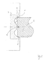
- Fig. 1 shows the first method step of a method for grinding the peripheral edge surface 1 of a glazing 2 by means of a grinding wheel 3.
- the edge surface 1 of the glazing 2 is guided past the grinding wheel 3 and / or the grinding wheel 3 is guided past the edge surface 1 of the glazing 2 ,
- the edge surface 1 in this case has an upper circumferential glass edge 4 and a lower peripheral glass edge 5 in the orientation shown.
- the grinding wheel 3 in turn has a peripheral circumferential grinding surface 6, which is mirror-symmetrical in such a way that the outer regions 7, 8 of the grinding surface 6 in rounded or bevelled shape in each case with respect to the central region of the grinding surface in the same way in the radial outward direction pointing are formed protruding.
- the distance between the outwardly protruding outer regions 7, 8 of the grinding surface is greater than the width of the edge surface 1 of the glazing 2, so that the edge surface 1 for grinding in the region between the above-formed outer regions 7, 8 of the grinding surface 6 is insertable.
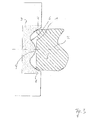
- the height of the projection 9 is formed smaller than the height of the rounded or bevelled edge portions 7, 8 of the grinding surface 3, so that the projection 9 only after the self-centering of the edge surface 1 of the glazing 2 by the rounded or beveled shape in the radial Direction outwardly protruding portions 7, 8 of the grinding surface 3 with the edge surface 1 is engaged.
- the desired contour of the edge surface 1 of the glazing 2 results lateral rounding of the glass edges 5, 6 and a depression 10 located between the glass edges 5, 6 includes.
Abstract
Description
Die Erfindung betrifft ein Verfahren zum Schleifen der umlaufenden Kantenfläche einer Verglasung, eine Verglasung sowie eine Schleifscheibe und ein System umfassend eine Verglasung und eine Schleifscheibe, jeweils entsprechend des Oberbegriffs des jeweiligen unabhängigen Patentanspruchs.The invention relates to a method for grinding the peripheral edge surface of a glazing, a glazing and a grinding wheel and a system comprising a glazing and a grinding wheel, each according to the preamble of the respective independent claim.
Aus der Praxis ist bekannt, die Kantenfläche von Verglasungen durch Vorbeiführen der Kantenfläche an der Schleifscheibe oder Vorbeiführen der Schleifscheibe an der Kantenfläche , derart zu schleifen, dass die Form der Kantenfläche nach erfolgtem Schleifen derart spiegelsymmetrisch ausgebildet ist, dass der Bereich der beiden umlaufenden Glaskanten in jeweils gegenüber dem mittleren Bereich in Richtung der Mitte der Verglasung in gleicher Weise in abgerundeter bzw. abgeschrägter Form zurückweichend ausgebildet ist.From practice, it is known to grind the edge surface of glazing by passing the edge surface on the grinding wheel or passing the grinding wheel on the edge surface in such a way that the shape of the edge surface after mirroring is mirror-symmetrical in such a way that the area of the two circumferential glass edges in in each case opposite to the central region in the direction of the center of the glazing in the same way in rounded or bevelled form receding formed.
Nachteilig hierbei ist, dass eine Befestigung einer derart geschliffenen Verglasung in einer umlaufenden Gummilippe insbesondere dann nicht sicher möglich ist, wenn die Kontur der geschliffenen Kantenfläche der Verglasung, die im Idealfall in etwa gleichmäßig konvex entsprechend einem Kreisringsegment ausgebildet ist, durch Verschleiß an der Schleifscheibe eher flach wird.The disadvantage here is that an attachment of such a ground glazing in a circumferential rubber lip in particular is not sure possible if the contour of the ground edge surface of the glazing, which in the ideal case approximately uniformly convex in accordance with a Annular segment is formed, rather flat due to wear on the grinding wheel.
Aufgabe der Erfindung ist es, die vorgenannten Nachteile zu vermeiden und eine Möglichkeit für eine verbesserte Haltemöglichkeit einer Verglasung bei Anordnung der umlaufenden Kantenfläche in einer umlaufenden Gummilippe anzugeben.The object of the invention is to avoid the aforementioned disadvantages and to provide a possibility for improved retention of a glazing in the arrangement of the peripheral edge surface in a circumferential rubber lip.
Diese Aufgabe wird gelöst durch ein Verfahren zum Schleifen der umlaufenden Kantenfläche einer Verglasung, eine Verglasung sowie eine Schleifscheibe und ein System umfassend eine Verglasung und eine Schleifscheibe, jeweils entsprechend dem kennzeichnenden Teil des jeweiligen unabhängigen Patentanspruchs. Dabei können kartesische und/oder polare Kinematiken eingesetzt werden.This object is achieved by a method for grinding the peripheral edge surface of a glazing, a glazing and a grinding wheel and a system comprising a glazing and a grinding wheel, each according to the characterizing part of the respective independent claim. In this case, Cartesian and / or polar kinematics can be used.
Insoweit wird bei einem erfindungsgemäßen Verfahren zum Schleifen der umlaufenden Kantenfläche einer Verglasung, insbesondere Schiebedachverglasung, mittels einer Schleifscheibe die Kantenfläche der Verglasung an der Schleifscheibe vorbeigeführt. Dabei kann die Schleifscheibe stationär angeordnet sein und die Glasscheibe kann mittels Saugnäpfen, beispielsweise mittels zweier oder mehrerer Saugnäpfe, die vorzugsweise in ihrem mittleren Bereich angreifen können, gehalten sein. Die Saugnäpfe können auch bis dicht an die Außenkanten heranreichend vorgesehen seinIn that regard, in a method according to the invention for grinding the peripheral edge surface of a glazing, in particular sunroof glazing, the edge surface of the glazing is guided past the grinding wheel by means of a grinding wheel. In this case, the grinding wheel can be arranged stationary and the glass pane can be held by means of suction cups, for example by means of two or more suction cups, which can preferably engage in their central area. The suction cups may also be provided close enough to the outer edges
Die umlaufende Kantenfläche ist aufgrund der entfernt von der Kantenfläche angeordneten Saugnäpfe in orthogonal zu der Ebene der Verglasung weisender Richtung auslenkbar, so dass sie eine gewisse Bewegung in dieser Richtung machen kann.The peripheral edge surface is deflectable due to the suction cups arranged away from the edge surface in a direction orthogonal to the plane of the glazing, so that it can make a certain movement in this direction.
Die Schleifscheibe weist eine in Umfangsrichtung umlaufende Schleiffläche auf, die derart spiegelsymmetrisch ausgebildet ist, dass die äußeren Bereiche der Schleiffläche in abgerundeter bzw. abgeschrägter Form jeweils gegenüber dem mittleren Bereich der Schleiffläche in gleicher Weise nach außen weisend vorstehend ausgebildet sind.The grinding wheel has a peripheral circumferential grinding surface, which is formed mirror-symmetrically such that the outer regions of the grinding surface in rounded or chamfered shape in each case opposite the central region of the grinding surface in the same way outwardly protruding.
Dabei ist der Abstand zwischen den nach außen weisend vorstehend ausgebildeten äußeren Bereichen der Schleiffläche derart ausgebildet, dass die Kantenfläche zum Schleifen in den Bereich zwischen den beiden vorstehend ausgebildeten äußeren Bereichen der Schleiffläche einführbar ist. Sobald zumindest eine Kante der Kantenfläche der Verglasung mit dem entsprechenden vorstehend ausgebildeten äußeren Bereich der Schleiffläche in Kontakt kommt, findet eine in Richtung des anderen vorstehend ausgebildeten äußeren Bereichs der Schleiffläche weisende Verlagerung der Kantenfläche der Verglasung statt. Somit erfolgt aufgrund der abgerundeten bzw. abgeschrägten Form der nach außen weisend vorstehenden Bereiche der Schleiffläche eine Selbstzentrierung der Kantenfläche innerhalb der Schleifscheibe.In this case, the distance between the outwardly projecting protruding outer regions of the grinding surface is formed such that the edge surface for grinding in the region between the two previously formed outer regions of the grinding surface is insertable. As soon as at least one edge of the edge surface of the glazing comes into contact with the corresponding protruding outer region of the grinding surface, a displacement of the edge surface of the glazing towards the other protruding outer region of the grinding surface takes place. Thus, due to the rounded or tapered shape of the outwardly facing projecting portions of the grinding surface, self-centering of the edge surface within the grinding wheel occurs.
Erfindungsgemäß wird eine Schleifscheibe zum Schleifen verwendet, deren umlaufende Schleiffläche zusätzlich mit wenigstens einem zwischen ihren beiden Seitenkanten vorgesehenen umlaufenden Vorsprung versehen ist. Dieser ist dabei so ausgebildet, dass dieser wenigstens eine umlaufende Vorsprung erst nach erfolgter Selbstzentrierung der Kantenfläche der Verglasung durch die abgerundete bzw. abgeschrägte Form der nach außen weisend vorstehenden Bereiche der Schleiffläche mit der Kantenfläche in Eingriff kommt.According to the invention a grinding wheel is used for grinding, the peripheral grinding surface is additionally provided with at least one provided between its two side edges circumferential projection. This is designed so that this comes at least one circumferential projection only after the self-centering of the edge surface of the glazing by the rounded or beveled shape of the outwardly facing projecting portions of the grinding surface with the edge surface.
Somit wird die Kantenfläche der Verglasung mit einer Form versehen, die einerseits in Bezug auf die Kantenbereiche derart spiegelsymmetrisch ausgebildet ist, dass sowohl der Bereich der oberen umlaufenden Glaskante als auch der Bereich der unteren umlaufenden Glaskante in abgerundeter bzw. abgeschrägter Form jeweils gegenüber dem mittleren Bereich in Richtung der Mitte der Verglasung in gleicher Weise zurückweichend ausgebildet sind, die jedoch andererseits zusätzlich mit wenigstens einer zwischen der oberen und der unteren Glaskante vorgesehenen umlaufenden Nut versehen ist, wobei diese Nut an jeder Stelle entlang der umlaufenden Kantenfläche immer an derselben Position der Kantenfläche, bezogen auf die Mitte der Kantenfläche, angeordnet ist. Sofern also die Nut mittig oder auf einem Viertel der Breite der Kantenfläche vorgesehen ist, ist sie dies auch bei durch Dickentoleranzen der Verglasung schwankender Breite der Kantenfläche entlang des gesamten Verlaufs der Kantenfläche.Thus, the edge surface of the glazing is provided with a shape that is so mirror-symmetrical on the one hand with respect to the edge regions, that both the region of the upper circumferential glass edge and the region of the lower circumferential glass edge in a rounded or chamfered shape respectively with respect to the central region formed in the same manner receding in the direction of the center of the glazing, but on the other hand additionally provided with at least one provided between the upper and the lower edge of the glass peripheral groove, said groove at each point along the peripheral edge surface always at the same position of the edge surface, relative to the center of the edge surface, is arranged. Thus, if the groove is provided in the middle or at a quarter of the width of the edge surface, this is also the case with thickness of the edge surface which fluctuates due to thickness tolerances of the glazing along the entire course of the edge surface.
Dabei ist die Tiefe der wenigstens einen Nut der Kantenfläche der Verglasung geringer als die Tiefe der abgerundeten bzw. abgeschrägten Kantenbereiche, und die Höhe des wenigstens einen Vorsprungs der Schleiffläche ist geringer als die Höhe der abgerundeten bzw. abgeschrägten Kantenbereiche der Schleiffläche.The depth of the at least one groove of the edge surface of the glazing is less than the depth of the rounded edge portions and the height of the at least one protrusion of the abrasive surface is less than the height of the rounded edge portions of the abrasive surface.
Die geometrischen Abmessungen der Kantenfläche der Verglasung und die geometrischen Abmessungen der Schleiffläche der Schleifscheibe sind dabei derart aufeinander abgestimmt, dass der wenigstens eine umlaufende Vorsprung der Schleifscheibe erst nach erfolgter Selbstzentrierung der Kantenfläche der Verglasung durch die abgerundete bzw. abgeschrägte Form der nach außen weisend vorstehenden Bereiche der Schleiffläche mit der Kantenfläche in Eingriff kommt. Somit erfolgt zuerst eine Zentrierung der Kantenfläche der Verglasung in Relation zu Schleiffläche der Verglasung, bevor das Schleifen der zumindest einen Nut beginnt. Hierdurch wird die relative einheitliche Position der wenigsten einen Nut bezogen auf die Breite der Kantenfläche bewirkt.The geometric dimensions of the edge surface of the glazing and the geometric dimensions of the grinding surface of the grinding wheel are matched to one another such that the at least one circumferential projection of the grinding wheel only after the self-centering of the edge surface of the glazing by the rounded or beveled shape of the outwardly projecting portions the grinding surface with the edge surface in engagement comes. Thus, first of all, the edge surface of the glazing is centered in relation to the glazing surface of the glazing before the grinding of the at least one groove begins. As a result, the relatively uniform position of at least one groove is effected based on the width of the edge surface.
Im Folgenden werden in den Zeichnungen dargestellte Ausführungsbeispiele der Erfindung erläutert. Es zeigen:Embodiments of the invention illustrated in the drawings are explained below. Show it:
Im Folgenden wird anhand entsprechender Zeichnungen ein Ausführungsbeispiel der Erfindung erläutert. Es zeigen:
- Fig. 1
- den ersten Verfahrensschritt eines erfindungsgemäßen Verfahrens,
- Fig. 2
- den zweiten Verfahrensschritt eines erfindungsgemäßen Verfahrens,
- Fig. 3
- den dritten Verfahrensschritt eines erfindungsgemäßen Verfahrens und
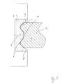
- Fig. 4
- den letzten Verfahrensschritt eines erfindungsgemäßen Verfahrens.
- Fig. 1
- the first process step of a process according to the invention,
- Fig. 2
- the second process step of a process according to the invention,
- Fig. 3
- the third process step of a method according to the invention and
- Fig. 4
- the last step of a method according to the invention.
In allen Figuren werden für gleiche bzw. gleichartige Bauteile übereinstimmende Bezugszeichen verwendet.In all figures the same reference numerals are used for identical or similar components.
Die Kantenfläche 1 weist dabei eine bei der gezeigten Ausrichtung obere umlaufende Glaskante 4 und eine untere umlaufende Glaskante 5 auf.The
Die Schleifscheibe 3 wiederum weist eine in Umfangsrichtung umlaufende Schleiffläche 6 auf, die derart spiegelsymmetrisch ausgebildet ist, dass die äußeren Bereiche 7, 8 der Schleiffläche 6 in abgerundeter bzw. abgeschrägter Form jeweils gegenüber dem mittleren Bereich der Schleiffläche in gleicher Weise in radialer Richtung nach außen weisend vorstehend ausgebildet sind.The grinding
Dabei ist der Abstand zwischen den nach außen weisend vorstehend ausgebildeten äußeren Bereichen 7, 8 der Schleiffläche größer als die Breite der Kantenfläche 1 der Verglasung 2, so dass die Kantenfläche 1 zum Schleifen in den Bereich zwischen den vorstehend ausgebildeten äußeren Bereichen 7, 8 der Schleiffläche 6 einführbar ist.In this case, the distance between the outwardly protruding
Aufgrund der abgerundeten bzw. abgeschrägten Form der nach außen weisend vorstehenden Bereiche 7, 8 der Schleiffläche 6 erfolgt, wie in
Wie aus
Dabei ist die Höhe des Vorsprungs 9 geringer ausgebildet als die Höhe der abgerundeten bzw. abgeschrägten Kantenbereiche 7, 8 der Schleiffläche 3, so dass der Vorsprung 9 erst nach erfolgter Selbstzentrierung der Kantenfläche 1 der Verglasung 2 durch die abgerundete bzw. abgeschrägte Form der in radialer Richtung nach außen weisend vorstehenden Bereiche 7, 8 der Schleiffläche 3 mit der Kantenfläche 1 in Eingriff kommt.The height of the projection 9 is formed smaller than the height of the rounded or
Somit resultiert durch den fortgesetzten (Schleif-)Kontakt zwischen der Schleifscheibe 3 und der Kantenfläche 1 der Verglasung 2 die erwünschte Kontur der Kantenfläche 1 der Verglasung 2, welche seitliche Verrundungen der Glaskanten 5, 6 sowie eine zwischen den Glaskanten 5, 6 befindliche Vertiefung 10 umfasst.Thus, due to the continued (grinding) contact between the
Claims (9)
Priority Applications (1)
| Application Number | Priority Date | Filing Date | Title |
|---|---|---|---|
| EP11170781A EP2537634A1 (en) | 2011-06-21 | 2011-06-21 | Method for grinding the circulating edge surface of glazing |
Applications Claiming Priority (1)
| Application Number | Priority Date | Filing Date | Title |
|---|---|---|---|
| EP11170781A EP2537634A1 (en) | 2011-06-21 | 2011-06-21 | Method for grinding the circulating edge surface of glazing |
Publications (1)
| Publication Number | Publication Date |
|---|---|
| EP2537634A1 true EP2537634A1 (en) | 2012-12-26 |
Family
ID=44587654
Family Applications (1)
| Application Number | Title | Priority Date | Filing Date |
|---|---|---|---|
| EP11170781A Withdrawn EP2537634A1 (en) | 2011-06-21 | 2011-06-21 | Method for grinding the circulating edge surface of glazing |
Country Status (1)
| Country | Link |
|---|---|
| EP (1) | EP2537634A1 (en) |
Cited By (2)
| Publication number | Priority date | Publication date | Assignee | Title |
|---|---|---|---|---|
| EP3053703A4 (en) * | 2013-10-04 | 2017-07-26 | Fujimi Incorporated | Polishing device and polishing method |
| CN110181418A (en) * | 2019-06-28 | 2019-08-30 | 江苏铁锚玻璃股份有限公司 | C-type emery wheel and preparation method thereof with gradual change notch |
Citations (4)
| Publication number | Priority date | Publication date | Assignee | Title |
|---|---|---|---|---|
| CH687913A5 (en) * | 1993-11-19 | 1997-03-27 | Bystronic Masch | Processing method of work pieces using grinding machine |
| EP0842904A1 (en) * | 1996-04-11 | 1998-05-20 | Nippon Sheet Glass Co., Ltd. | Thermally tempered flat glass and method of finishing edge portions of the same |
| US5908675A (en) * | 1995-08-10 | 1999-06-01 | Flachglas Automotive Gmbh | Glass laminate and method of making same |
| US20020054976A1 (en) * | 2000-07-21 | 2002-05-09 | Shoji Nakamura | Molded glass substrate for magnetic disk and method for manufacturing the same |
-
2011
- 2011-06-21 EP EP11170781A patent/EP2537634A1/en not_active Withdrawn
Patent Citations (4)
| Publication number | Priority date | Publication date | Assignee | Title |
|---|---|---|---|---|
| CH687913A5 (en) * | 1993-11-19 | 1997-03-27 | Bystronic Masch | Processing method of work pieces using grinding machine |
| US5908675A (en) * | 1995-08-10 | 1999-06-01 | Flachglas Automotive Gmbh | Glass laminate and method of making same |
| EP0842904A1 (en) * | 1996-04-11 | 1998-05-20 | Nippon Sheet Glass Co., Ltd. | Thermally tempered flat glass and method of finishing edge portions of the same |
| US20020054976A1 (en) * | 2000-07-21 | 2002-05-09 | Shoji Nakamura | Molded glass substrate for magnetic disk and method for manufacturing the same |
Cited By (2)
| Publication number | Priority date | Publication date | Assignee | Title |
|---|---|---|---|---|
| EP3053703A4 (en) * | 2013-10-04 | 2017-07-26 | Fujimi Incorporated | Polishing device and polishing method |
| CN110181418A (en) * | 2019-06-28 | 2019-08-30 | 江苏铁锚玻璃股份有限公司 | C-type emery wheel and preparation method thereof with gradual change notch |
Similar Documents
| Publication | Publication Date | Title |
|---|---|---|
| EP2616700A1 (en) | Peripheral sealing arrangement | |
| EP3003645B1 (en) | Screw drive | |
| EP2893207B1 (en) | Axial cage for cylindrical rolling elements | |
| DE102011010912A1 (en) | Brake pad assembly for a disc brake and method of making a brake pad assembly | |
| WO2013093900A1 (en) | Jaw or claw-shaped gap seal | |
| EP2537634A1 (en) | Method for grinding the circulating edge surface of glazing | |
| WO2018054416A1 (en) | Wheel bearing seal having an integrated outer seal | |
| EP2601422A2 (en) | Assembly for sealing a rotational connection | |
| EP2907776B1 (en) | Transport device with an endless belt-shaped transport element | |
| DE102018219757A1 (en) | Gap sealing for segmented roller bearings | |
| DE202011109164U1 (en) | Mouth or claw-shaped gap seal | |
| WO2017198265A4 (en) | End mill | |
| EP1490609A1 (en) | Ball screw provided with a deflection element | |
| WO2012019702A1 (en) | Abrasive brush | |
| DE102016210696B3 (en) | axial angle disk | |
| EP2527694B1 (en) | Jaw or claw shaped gap seal | |
| EP0441287B1 (en) | Metallic insert band for trimming and sealing strips | |
| DE102012213033A1 (en) | Method for manufacturing bearing ring for roller bearing, involves providing and reshaping annular disc in cylindrical bearing rings, manufacturing cylindrical raceways and forming boards under cylindrical raceways by extrusion molding | |
| DE102018212054B4 (en) | Component composite | |
| DE102014100979B4 (en) | bearing bush | |
| DE102020128146A1 (en) | Dynamic engagement seal device and system with improved contact behavior | |
| DE102010010487A1 (en) | Cage for ball joint and ball joint | |
| DE102017214198B4 (en) | Arrangement and method for the limited displacement of a tailpipe cover | |
| DE102019122836A1 (en) | Rotor assembly with an end ring notched with curved recesses and method of making the same | |
| DE102007029574A1 (en) | Leather repairing method, involves punching repairing section with relative edges of section around damaged spot of leather article that has to be repaired, and applying leather adhesive on diagonal edges of section |
Legal Events
| Date | Code | Title | Description |
|---|---|---|---|
| PUAI | Public reference made under article 153(3) epc to a published international application that has entered the european phase |
Free format text: ORIGINAL CODE: 0009012 |
|
| AK | Designated contracting states |
Kind code of ref document: A1 Designated state(s): AL AT BE BG CH CY CZ DE DK EE ES FI FR GB GR HR HU IE IS IT LI LT LU LV MC MK MT NL NO PL PT RO RS SE SI SK SM TR |
|
| AX | Request for extension of the european patent |
Extension state: BA ME |
|
| STAA | Information on the status of an ep patent application or granted ep patent |
Free format text: STATUS: THE APPLICATION HAS BEEN WITHDRAWN |
|
| 18W | Application withdrawn |
Effective date: 20130521 |