EP2537555A1 - Leadless autonomous intracardiac implant with disengageable attachment element - Google Patents
Leadless autonomous intracardiac implant with disengageable attachment element Download PDFInfo
- Publication number
- EP2537555A1 EP2537555A1 EP12164451A EP12164451A EP2537555A1 EP 2537555 A1 EP2537555 A1 EP 2537555A1 EP 12164451 A EP12164451 A EP 12164451A EP 12164451 A EP12164451 A EP 12164451A EP 2537555 A1 EP2537555 A1 EP 2537555A1
- Authority
- EP
- European Patent Office
- Prior art keywords
- capsule
- base
- tabs
- implant
- contact
- Prior art date
- Legal status (The legal status is an assumption and is not a legal conclusion. Google has not performed a legal analysis and makes no representation as to the accuracy of the status listed.)
- Granted
Links
Images


Classifications
-
- A—HUMAN NECESSITIES
- A61—MEDICAL OR VETERINARY SCIENCE; HYGIENE
- A61N—ELECTROTHERAPY; MAGNETOTHERAPY; RADIATION THERAPY; ULTRASOUND THERAPY
- A61N1/00—Electrotherapy; Circuits therefor
- A61N1/02—Details
- A61N1/04—Electrodes
- A61N1/05—Electrodes for implantation or insertion into the body, e.g. heart electrode
- A61N1/0587—Epicardial electrode systems; Endocardial electrodes piercing the pericardium
- A61N1/059—Anchoring means
-
- A—HUMAN NECESSITIES
- A61—MEDICAL OR VETERINARY SCIENCE; HYGIENE
- A61N—ELECTROTHERAPY; MAGNETOTHERAPY; RADIATION THERAPY; ULTRASOUND THERAPY
- A61N1/00—Electrotherapy; Circuits therefor
- A61N1/02—Details
- A61N1/04—Electrodes
- A61N1/05—Electrodes for implantation or insertion into the body, e.g. heart electrode
- A61N1/0587—Epicardial electrode systems; Endocardial electrodes piercing the pericardium
-
- A—HUMAN NECESSITIES
- A61—MEDICAL OR VETERINARY SCIENCE; HYGIENE
- A61N—ELECTROTHERAPY; MAGNETOTHERAPY; RADIATION THERAPY; ULTRASOUND THERAPY
- A61N1/00—Electrotherapy; Circuits therefor
- A61N1/18—Applying electric currents by contact electrodes
- A61N1/32—Applying electric currents by contact electrodes alternating or intermittent currents
- A61N1/36—Applying electric currents by contact electrodes alternating or intermittent currents for stimulation
- A61N1/362—Heart stimulators
- A61N1/365—Heart stimulators controlled by a physiological parameter, e.g. heart potential
- A61N1/36585—Heart stimulators controlled by a physiological parameter, e.g. heart potential controlled by two or more physical parameters
-
- A—HUMAN NECESSITIES
- A61—MEDICAL OR VETERINARY SCIENCE; HYGIENE
- A61N—ELECTROTHERAPY; MAGNETOTHERAPY; RADIATION THERAPY; ULTRASOUND THERAPY
- A61N1/00—Electrotherapy; Circuits therefor
- A61N1/18—Applying electric currents by contact electrodes
- A61N1/32—Applying electric currents by contact electrodes alternating or intermittent currents
- A61N1/36—Applying electric currents by contact electrodes alternating or intermittent currents for stimulation
- A61N1/372—Arrangements in connection with the implantation of stimulators
- A61N1/375—Constructional arrangements, e.g. casings
- A61N1/37518—Anchoring of the implants, e.g. fixation
-
- A—HUMAN NECESSITIES
- A61—MEDICAL OR VETERINARY SCIENCE; HYGIENE
- A61N—ELECTROTHERAPY; MAGNETOTHERAPY; RADIATION THERAPY; ULTRASOUND THERAPY
- A61N1/00—Electrotherapy; Circuits therefor
- A61N1/18—Applying electric currents by contact electrodes
- A61N1/32—Applying electric currents by contact electrodes alternating or intermittent currents
- A61N1/36—Applying electric currents by contact electrodes alternating or intermittent currents for stimulation
- A61N1/372—Arrangements in connection with the implantation of stimulators
- A61N1/375—Constructional arrangements, e.g. casings
- A61N1/3752—Details of casing-lead connections
-
- A—HUMAN NECESSITIES
- A61—MEDICAL OR VETERINARY SCIENCE; HYGIENE
- A61N—ELECTROTHERAPY; MAGNETOTHERAPY; RADIATION THERAPY; ULTRASOUND THERAPY
- A61N1/00—Electrotherapy; Circuits therefor
- A61N1/18—Applying electric currents by contact electrodes
- A61N1/32—Applying electric currents by contact electrodes alternating or intermittent currents
- A61N1/36—Applying electric currents by contact electrodes alternating or intermittent currents for stimulation
- A61N1/372—Arrangements in connection with the implantation of stimulators
- A61N1/375—Constructional arrangements, e.g. casings
- A61N1/3756—Casings with electrodes thereon, e.g. leadless stimulators
Definitions
- the invention relates generally to the field of "active medical devices” as defined by the Council of European Communities Directive 93/42 / EC of 14 June 1993, and in particular "active implantable medical devices” as defined by Council Directive 90/385 / EEC of 20 June 1990.
- This definition includes in particular the devices responsible for monitoring cardiac activity and generating pacing, resynchronization, defibrillation and / or cardioversion pulses in the event of arrhythmia detected by the device. It also includes neurological devices, cochlear implants, etc., as well as devices for measuring pH or intracorporeal impedance (such as measurement of transpulmonary impedance or intracardiac impedance).
- the invention relates more particularly to those devices that implement autonomous implants without any physical connection to an implanted main device (such as a stimulation pulse generator box) or not implanted (external device such as programmer). or monitoring device for remote monitoring of the patient).
- the communication is then of the wireless communication type.
- Such leadless implants are for example described in the US 2007/0088397 A1 and WO 2007/047681 A2 (Nanostim, Inc.) or in the US 2006/0136004 A1 (EBR Systems, Inc.).
- These leadless implants can be in particular epicardial implants attached to the outer wall of the heart, or endocavitary implants, attached to the inner wall of a ventricular or atrial cavity. Their attachment to the cardiac wall is usually done by means of a protruding helical anchoring screw, axially extending the body of the implant and intended to penetrate into the heart tissue by screwing to the implantation site.
- Such an implant comprises detection / stimulation circuits for collecting myocardial depolarization potentials and / or for applying stimulation pulses to the implantation site by means of appropriate electrodes carried by this implant. It can also incorporate one or more sensors to locally measure the value of a parameter such as the level of oxygen in the blood, the endocavitary cardiac pressure, the acceleration of the cardiac wall, the acceleration of the patient as an indicator of activity etc.
- the leadless implants also incorporate wireless communication transmitter / receiver means.
- the invention is however not limited to a particular type of implant, and it is applicable regardless of any type of leadless implant , regardless of its functional purpose.
- the energy source is one of the major weaknesses of lea dless implants , because, being autonomous, it is not possible to transmit energy to them via a probe conductor.
- energy recovery techniques have been proposed, to date only battery powered systems are truly operational. But given the very restrictive volume constraints, the autonomy of these batteries is limited, so that the currently proposed leadless implants have a limited life, of the order of six months to two years, and must be replaced regularly.
- the axis of attachment of the leadless implant (typically, the axis of the anchor screw) is the same as the insertion axis of the implant.
- this fastener is located at the end of the elongated cylindrical body constituting the body of the implant, which must necessarily be fixed perpendicularly to the cardiac wall. This configuration increases the invasiveness of the implanted system with respect to heart function, particularly because of the greater interference with blood flow and heart wall movement.
- the first element (base) will be fixed first on the chosen site. Then, the second element (capsule) will be inserted and then fixed to the base thanks to the coupling system.
- the coupling system includes protruding tabs disposed at two opposite ends of the base so as to define contact surfaces facing one another to conform to the shape of mating contact surfaces of the capsule.
- such an implant according to the invention can be adapted both to endocavitary leadless implants, of elongate shape (whose length is greater than the diameter), as to epicardial implants of a flatter shape ( whose diameter is greater than the length).
- the device of the invention comprises, which is of the type disclosed by the US2002 / 0165589 A1 aforementioned, that is to say comprising two distinct elements that can be fixed to one another and can be separated reversibly, with a sealed capsule housing electronic circuits, and a base comprising a plate having an outer surface carrying means for anchoring to a wall of an organ of a patient, as well as an inner face forming a support for the capsule and carrying means for mechanical coupling to the capsule, is characterized in that the mechanical coupling means from the base to the capsule comprise protruding tabs arranged at two opposite ends of the plate on the inner face thereof, these tabs being substantially parallel and defining on their faces vis-à-vis the contact surfaces adapted to marry the shape of conjugate contact surfaces of the capsule.
- the tabs may be elastically deformable, the contact surfaces of the base then having concavities vis-à-vis able to conform to the shape of convex conjugate contact surfaces of the capsule, so as to allow a reversible clipping of the capsule on the base.
- the tabs may be rigid, the contact surfaces of the base comprising for example a tapping adapted to engage threaded conjugate contact surfaces of the capsule, so as to allow a reversible screwing of the capsule on the base.
- the tabs comprise a curved notch adapted to engage homologous coupling fingers of the capsule, so as to allow a reversible bayonet type fitting of the capsule on the base.
- the base further comprises elastic biasing means of the capsule in the axial direction so as to allow locking in position of the capsule fixed on the base.
- the capsule comprises a body in the shape of a surface of revolution whose axis is oriented parallel to the axis of the anchoring means, and this body comprises, on its face turned towards the side of the base, at least one projecting support carrying an electrode surface capable of coming into contact with the tissues of the patient when the capsule is mounted on the base.
- a side wall of the projecting support adapted to come into contact with a flange of the plate so as to ensure locking in axial rotation of the capsule relative to the base.
- the capsule comprises a body provided with electrodes coupled to contacts arranged on the inner portion of the base, these contacts being themselves connected to electrodes formed on the outer portion of the base and adapted to come into contact with the wall of the patient's body.
- the body comprises, on its opposite side to that turned on the side of the base, a cover carrying a conductive surface forming a ground electrode, adapted to come into contact with a body fluid of the patient's body when the capsule is mounted on the base.
- This first embodiment is particularly suitable for an embodiment where the body comprises, on its opposite side to that turned on the side of the base, means for attachment to an additional element separable from the body without separation of the body and the base, the capsule being formed by the stack of the body and the additional element.
- the additional element can in particular house a battery supply electronic circuits housed in the body.
- the capsule comprises a body shaped surface of revolution whose axis is oriented perpendicular to the axis of the anchoring means, and wherein the body comprises, on at least one region of axial end, an annular ring carrying an electrode surface adapted to come into contact with the tissues of the patient when the capsule is mounted on the base.
- the capsule and / or the base may advantageously be provided with radiopaque markers, in order to facilitate subsequent extraction of the capsule and then of placing a new capsule on the base, remained implanted in situ.
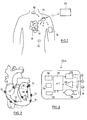
- FIG. 1 there is illustrated a set of medical devices implanted within the body of a patient.
- the patient is equipped for example with a device 10 such as an implanted defibrillator / stimulator / resynchronizer, or a subcutaneous defibrillator, or a long-term recorder.
- This device 10 is the master device of a network comprising a plurality of slave devices 12 to 18 with which it is capable of communicating via the HBC ( Human Body Communication ) communication.
- HBC Human Body Communication
- These may in particular include intracardiac or epicardial devices 14 implanted directly on the patient's heart, other devices 16 such as myopotential sensors or neurological stimulation devices, and possibly an external device 18 disposed on an armband and provided with electrodes in contact with the skin.
- the master device 10 can also be used as a gateway with the outside world to communicate with an external device 20 of the programmer or device type. teletransmission of data with which it can communicate including RF telemetry.
- Each of the devices 10 to 18 is provided with at least a pair of electrodes which are in direct contact with the body tissues for the implanted devices, or in contact with the skin for the external device 18.
- lea dless- type devices implanted either on the inner part of the myocardium, in an atrial or ventricular cavity (endocavitary implants 12), or on an external wall of this same myocardium (epicardial implants 14) have been shown.
- These devices are attached to the cardiac wall by means of a protruding anchoring screw intended to penetrate the cardiac tissue by screwing to the implantation site.
- the screw can be either a passive screw, serving only for fixation of the implant, or an active screw, used to collect the depolarization signals propagating in the myocardial tissues and / or to deliver stimulation pulses to the patient.
- implantation site in a localized way.
- the Figure 3 schematically illustrates the different internal circuits of the implants 12 or 14.
- Each implant comprises a pair of electrodes 22, 24 connected to a stimulation pulse generating circuit 26 (for an active implant incorporating this function) and / or to a detection circuit 28 serving to collect the depolarization potentials collected between the electrodes 22 and 24.
- a central circuit 30 includes all of the electronics used to control the various functions of the implant, the memorization of the signals collected, etc. It comprises a microcontroller and an oscillator generating the clock signals necessary for the operation of the microcontroller and for communication. It can also contain an analog / digital converter and a digital storage memory.
- the implant may also be provided with a sensor 32 such as an acceleration sensor, a pressure sensor, a hemodynamic sensor, a temperature sensor, an oxygen saturation sensor, etc.
- the implant comprises a small battery or a power recovery circuit 34 supplying all the circuits via a power management stage 36.
- the electrodes 22 and 24 are also connected to a modulator / demodulator circuit 38 coupled to the circuit central processor 30 and able to transmit and / or receive pulses for communication wireless HBC.
- the electrodes 22, 24 can provide a single, double or triple function, namely: stimulation and / or collection of cardiac potentials (where applicable) and / or transmission of the information tracked by the sensor 32 (if applicable); and send / receive for HBC communication (in any case).
- the implant 12 or 14 comprises a capsule 100 mounted on a base 200 by means of a reversible coupling.
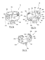
- FIGS. 4a to 4e illustrate a first embodiment of the implant according to the invention, for an epicardial capsule with fixing by clipping of the capsule to the base.
- the capsule 100 comprises a flattened cylindrical body, typically a few millimeters thick and 8 to 12 mm in diameter, closed by a cover 104 at its upper part (that is to say on the side opposite to the wall on which the implant is intended to be fixed).
- the body of the capsule 100 can be made of titanium, according to a conventional technology for stamping a thin implantable titanium blade conforming to ISO 5832-2, or any other biocompatible metal.
- the capsule may be made of a biocompatible plastic material, by molding or any other technique for encapsulating the internal components housed in the body of the capsule.
- This plastic material may for example be a Tecothane (registered trademark), which is a thermoplastic polyurethane based on aromatic polyether of medical grade, radio-opaque or not.
- the capsule 100 On its underside 106 (see in particular Figure 4d ) the capsule 100 comprises two salient elements 108 whose surface intended to come into contact with the cardiac tissues, carries electrodes 22, 24 of detection / stimulation / defibrillation. These electrodes have an area of a few square millimeters to a few tens of square millimeters.
- the capsule 100 encloses a circuit 110 carrying the active elements, the battery, the sensors, the connections to the electrodes, etc.
- This circuit 110 is housed in the body 102 of the capsule which is sealed by the cover 104, for example by welding to the cylindrical body 102.
- the central portion of the cover 104 may optionally carry a conductive surface 112 forming a ground electrode, isolated from the rest of the body by a peripheral ring 114 of insulating material.
- the base 200 comprises a plate 202 on which bears the lower surface 106 of the body 102.
- the lower face of the plate 202 carries the anchoring means to the heart wall, in this case a helical screw 204 from 2 to 3 mm in diameter.
- the plate 202 is provided at each of its ends with a tab 206 elastically deformable.
- the platinum assembly 202 / tabs 206 is advantageously made of Tecothane (registered trademark) of medical grade.
- the tabs 206 extend upwardly in a substantially parallel manner and have in their facing faces a slight concavity 208, matching the shape of the conjugate, slightly convex peripheral surface of the body 102 of the capsule, so that to ensure the retention of the capsule 100 by clipping the body 102 between the two tabs 206 elastically deformable.
- the salient elements 108 of the capsule 100 which carry the respective electrodes 22 and 24, fit without play or with a very weak clearance against the flanges 210 of the central part of the plate 202, which makes it possible to block the capsule 100 in rotation relative to the base 200 and thus avoids any modification of the stimulation zones, that is to say zones of the cardiac wall situated in contact with each of the two electrodes 22 and 24.
- the thickness of the projecting elements 108 must be greater than the thickness of the central portion of the plate 202.
- the stimulation electrodes (and / or detection) in contact with the tissues to be stimulated are formed on the base and not on the capsule.
- the body 102 of the capsule is provided with electrodes coupled to contacts arranged on the inner part of the base 200, contacts themselves connected to electrodes on the outer part of the base, in contact with tissues.
- This embodiment in particular makes it possible to provide stimulation via the fastening means of the base on the tissues, for example by the anchoring screw 204.
- the base 200 and / or the capsule 100 may be provided with radiopaque markers, in order subsequently to facilitate the extraction operations of the capsule and then to set up a new capsule. on the base, remained implanted in situ.
- FIGS. 5a and 5b illustrate a second embodiment of the implant according to the invention, for an endocavitary capsule with fixing by clipping of the capsule to the base.
- the capsule 100 is in the form of an oblong element with an elongated body terminated by two ogival ends 118.
- the capsule has a longitudinal dimension of the order of 10 mm, for a diameter maximum of a few millimeters.
- the body of the capsule 100 is disposed with its axis D 1 oriented in a direction substantially parallel to the heart wall, that is to say perpendicular to the axis D 2 of the means of anchoring 204 of the base 200 - unlike the previous embodiment illustrated Figures 4a to 4e , where these two axes were aligned and merged.
- the base comprises two elastic tabs 214 defining, on the inside, a concave surface 216 homologous to the outer surface 116 of the capsule 100.
- the length of the tabs 214 is such that the ends 220 of these are located beyond the diametral region of the capsule 100, so as to ensure the retention in place thereof after the latter has been fitted into the base.
- the capsule 100 is provided on either side of the base 200 with two annular rings 120 arranged in the vicinity of the ogival-shaped ends 118 and carrying the electrodes 22, 24 in the form of conductive surfaces on the whole periphery of the rings. rings 120.
- This configuration allows contact with the cardiac tissues regardless of how the capsule 100, which has a symmetry of revolution about the axis D 1 , has been nested on the base 200.Ille also allows to provide a spacing relatively large between the two electrodes 22 and 24, favorable to an effective stimulation.
- the small diameter (a few millimeters) of the capsule allows a low traumatic introduction to the implantation site.
- the capsule is then turned a quarter of a turn at the time of its nesting on the base 200, so as to orient perpendicularly the axis D 1 of the capsule relative to the axis D 2 of the base and the anchor screw.
- the system comprises several, typically two, bases fixed side by side on the heart wall and on which fits a single capsule.
- the implant is thus fixed to the wall in several, typically two, places, which increases the contact surface and provides greater freedom in the choice of stimulation sites, and better holding mechanical because of the absence of axis of rotation or preferred flexion.
- FIGS. 6a and 6b illustrate a third embodiment of the implant according to the invention, for an epicardial capsule with fixing by screwing the capsule on the base.
- the lugs 206 of the base 200 are provided on their inner face with a tapping 224 adapted to cooperate with a homologous thread 122 formed on the outer surface of the body 102 of the capsule 100.
- the implementation of the capsule on the base is then made by screwing, the cover 104 of the capsule being advantageously provided with recesses 124 for engaging a drive tool in rotation of the capsule.
- the implant may comprise a plurality of stackable bodies such as 102, 102 ': the body 102 comprises the attachment means to the base and encloses for example all the electronic circuits, while the body 102 'superimposed on the body 102 contains the supply battery so that it can be replaced leaving in place the body 102 mounted on the base.
- FIGS. 7a to 7c illustrate a fourth embodiment of the implant according to the invention, for an epicardial capsule with fixing by a bayonet system of the capsule to the base.
- the tabs 206 carry a curved guide notch 226, 228 cooperating with a coupling finger 126 made on the side wall of the capsule 100.
- the installation is done in the manner of a bayonet of a base of electric lamp, by a pushed-turned movement.
- the holding in place is provided by elastic elements 230 formed on the plate 202. These elastic elements ensure, once the positioning movement completed, the plating of the coupling finger 126 in the bottom 228 of the curved guide slot 226.
- the stimulation electrodes 22, 24 are carried by protruding elements such as 128 formed on the lower surface of the body of the capsule 100 and intended to come into contact with the cardiac tissues once the capsule is nested on the body. 'base.
Abstract
Description
L'invention concerne, de façon générale, le domaine des "dispositifs médicaux actifs" tels que définis par la directive 93/42/CE du 14 juin 1993 du Conseil des communautés européennes, et notamment les "dispositifs médicaux implantables actifs" tels que définis par la directive du Conseil 90/385/CEE du 20 juin 1990.The invention relates generally to the field of "active medical devices" as defined by the Council of European Communities Directive 93/42 / EC of 14 June 1993, and in particular "active implantable medical devices" as defined by Council Directive 90/385 / EEC of 20 June 1990.
Cette définition inclut en particulier les appareils chargés de surveiller l'activité cardiaque et de générer des impulsions de stimulation, de resynchronisation, de défibrillation et/ou de cardioversion en cas de trouble du rythme détecté par l'appareil. Elle inclut aussi les appareils neurologiques, les implants cochléaires, etc., ainsi que les dispositifs de mesure de pH ou encore d'impédance intracorporelle (telle que mesure d'impédance transpulmonaire ou d'impédance intracardiaque).This definition includes in particular the devices responsible for monitoring cardiac activity and generating pacing, resynchronization, defibrillation and / or cardioversion pulses in the event of arrhythmia detected by the device. It also includes neurological devices, cochlear implants, etc., as well as devices for measuring pH or intracorporeal impedance (such as measurement of transpulmonary impedance or intracardiac impedance).
L'invention concerne plus particulièrement ceux de ces dispositifs qui mettent en oeuvre des implants autonomes dépourvus de toute liaison physique à un dispositif principal implanté (tel qu'un boîtier de générateur d'impulsions de stimulation) ou non implanté (périphérique externe tel que programmateur ou dispositif de monitoring pour le suivi à distance du patient). La communication est alors du type communication sans fil.The invention relates more particularly to those devices that implement autonomous implants without any physical connection to an implanted main device (such as a stimulation pulse generator box) or not implanted (external device such as programmer). or monitoring device for remote monitoring of the patient). The communication is then of the wireless communication type.
Ces implants autonomes sont dénommées pour cette raison "implants leadless", pour les distinguer des électrodes ou des capteurs disposés à l'extrémité distale d'une sonde (lead), cette sonde étant parcourue sur toute sa longueur par un ou plusieurs conducteurs reliant par voie galvanique l'électrode ou le capteur à un générateur connecté à l'extrémité opposée, proximale, de la sonde.These autonomous implants are called for this reason " leadless implants", to distinguish them from the electrodes or sensors arranged at the distal end of a probe ( lead ) , this probe being traversed along its length by one or more connecting conductors by Galvanically route the electrode or sensor to a generator connected to the opposite, proximal end of the probe.
De tels implants leadless sont par exemple décrites dans les
Ces implants leadless peuvent être notamment des implants épicardiques, fixés à la paroi extérieure du coeur, ou bien des implants endocavitaires, fixés à la paroi intérieure d'une cavité ventriculaire ou auriculaire. Leur fixation à la paroi cardiaque se fait habituellement au moyen d'une vis d'ancrage hélicoïdale saillante, prolongeant axialement le corps de l'implant et destinée à pénétrer dans le tissu cardiaque par vissage au site d'implantation.These leadless implants can be in particular epicardial implants attached to the outer wall of the heart, or endocavitary implants, attached to the inner wall of a ventricular or atrial cavity. Their attachment to the cardiac wall is usually done by means of a protruding helical anchoring screw, axially extending the body of the implant and intended to penetrate into the heart tissue by screwing to the implantation site.
Un tel implant comprend des circuits de détection/stimulation pour recueillir des potentiels de dépolarisation du myocarde et/ou pour appliquer des impulsions de stimulation au site d'implantation, au moyen d'électrodes appropriées portées par cet implant. Il peut également incorporer un ou plusieurs capteurs permettant de mesurer localement la valeur d'un paramètre tel que le niveau d'oxygène dans le sang, la pression cardiaque endocavitaire, l'accélération de la paroi cardiaque, l'accélération du patient comme indicateur de l'activité etc. Bien entendu, pour permettre l'échange de données à distance, les implants leadless incorporent également des moyens émetteurs/récepteurs de communication sans fil.Such an implant comprises detection / stimulation circuits for collecting myocardial depolarization potentials and / or for applying stimulation pulses to the implantation site by means of appropriate electrodes carried by this implant. It can also incorporate one or more sensors to locally measure the value of a parameter such as the level of oxygen in the blood, the endocavitary cardiac pressure, the acceleration of the cardiac wall, the acceleration of the patient as an indicator of activity etc. Of course, to allow remote data exchange, the leadless implants also incorporate wireless communication transmitter / receiver means.
L'invention n'est toutefois pas limitée à un type particulier d'implant, et elle est applicable indifféremment à tout type d'implant leadless, quel que soit sa destination fonctionnelle.The invention is however not limited to a particular type of implant, and it is applicable regardless of any type of leadless implant , regardless of its functional purpose.
À cet égard, le
La source d'énergie est l'un des points faibles majeurs des implants leadless, car, étant autonomes, il n'est pas possible de leur transmettre de l'énergie par un conducteur de sonde. Même si des techniques de récupération d'énergie ont été proposées, à ce jour seuls les systèmes d'alimentation par piles sont véritablement opérationnels. Mais compte tenu des contraintes de volume très restrictives, l'autonomie de ces piles est limitée, de sorte que les implants leadless actuellement proposés présentent une durée de vie limitée, de l'ordre de six mois à deux ans, et doivent donc être remplacés régulièrement.The energy source is one of the major weaknesses of lea dless implants , because, being autonomous, it is not possible to transmit energy to them via a probe conductor. Although energy recovery techniques have been proposed, to date only battery powered systems are truly operational. But given the very restrictive volume constraints, the autonomy of these batteries is limited, so that the currently proposed leadless implants have a limited life, of the order of six months to two years, and must be replaced regularly.
Le remplacement d'un implant leadless, outre la réitération fréquente d'une opération particulièrement invasive, entraîne plusieurs difficultés :
- en premier lieu, l'ancien site d'implantation, qui était peut-être optimal (notamment s'il a été déterminé à la suite d'un mapping) n'est pas retrouvable facilement ;
- d'autre part, des traumatismes supplémentaires sont causés aux tissus par le retrait de l'ancien implant et la fixation du nouveau ;
- enfin, lorsque l'implant en fin de vie ne peut pas être retiré et doit être laissé en place, il constitue un corps étranger invasif et parasite, ce qui peut s'avérer très problématique au fil des ans et des implantations successives.
- in the first place, the old implantation site, which was perhaps optimal (especially if it was determined as a result of a mapping ) is not easy to retrieve;
- on the other hand, additional trauma is caused to the tissues by removing the old implant and fixing the new one;
- and finally, when the end-of-life implant can not be removed and needs to be left in place, it is an invasive and parasitic foreign body. can be very problematic over the years and successive implementations.
Les problèmes ci-dessus se posent d'ailleurs quelle que soit la cause du remplacement de l'implant leadless : défaut d'un circuit électronique, remplacement par une version plus récente, élément générant une infection, etc.The above problems arise besides whatever the cause of the replacement of the leadless implant: defect of an electronic circuit, replacement by a newer version, element generating an infection, etc.
De surcroît, l'introduction jusqu'au site d'implantation d'un implant leadless de dimension relativement importante nécessite des outils de taille adaptée, dont l'utilisation peut s'avérer traumatique pour le patient.In addition, the introduction to the implantation site of a relatively large leadless implant requires tools of suitable size, the use of which can be traumatic for the patient.
Enfin, dans tous les systèmes jusqu'à présent proposés, l'axe de fixation de l'implant leadless (typiquement, l'axe de la vis d'ancrage) est le même que l'axe d'introduction de l'implant. Pour un implant endocavitaire, cela signifie que cet élément de fixation se situe au bout du corps cylindrique allongé constituant le corps de l'implant, qui doit donc être obligatoirement fixé perpendiculairement à la paroi cardiaque. Cette configuration augmente l'invasivité du système implanté par rapport au fonctionnement du coeur, notamment du fait de l'interférence plus importante avec le flux sanguin et le mouvement des parois cardiaques.Finally, in all the systems heretofore proposed, the axis of attachment of the leadless implant (typically, the axis of the anchor screw) is the same as the insertion axis of the implant. For an endocavitary implant, this means that this fastener is located at the end of the elongated cylindrical body constituting the body of the implant, which must necessarily be fixed perpendicularly to the cardiac wall. This configuration increases the invasiveness of the implanted system with respect to heart function, particularly because of the greater interference with blood flow and heart wall movement.
Le but de l'invention est de proposer un dispositif de type implant leadless permettant de pallier ces différents inconvénients en permettant notamment, lorsque l'implant doit être renouvelé :
- de réutiliser le site d'implantation initial ;
- de minimiser les traumatismes sur les tissus au site d'implantation ;
- si l'implant doit être retiré, de permettre ce retrait sans laisser subsister sur le site d'implantation d'éléments volumineux ;
- de minimiser l'invasivité lors de l'implantation ; et
- d'augmenter la liberté de conception de la forme de l'implant, notamment en évitant de concevoir un élément allongé implantable dont après implantation la plus grande dimension serait perpendiculaire à la paroi cardiaque.
- to reuse the initial site of implantation;
- Minimize tissue trauma at the site of implantation
- if the implant is to be removed, to allow this removal without leaving on the implantation site of bulky elements;
- to minimize invasiveness during implantation; and
- to increase the freedom of conception of the shape of the implant, in particular by avoiding designing an elongated implantable element which after implantation the largest dimension would be perpendicular to the cardiac wall.
Comme dans le
- un premier élément ou "embase", dédié à la fixation à la paroi cardiaque, comprenant les moyens d'ancrage usuels tels que vis, harpon, crochet ou autre ; et
- un second élément ou "capsule" incorporant les principaux organes actifs de l'implant (électronique et sources d'énergie),
- les deux éléments étant couplés de manière réversible par un système de fixation tel que clip, vis, baïonnette ou autre.
- a first element or "base", dedicated to the attachment to the cardiac wall, comprising the usual anchoring means such as screws, harpoon, hook or other; and
- a second element or "capsule" incorporating the main active organs of the implant (electronics and energy sources),
- the two elements being reversibly coupled by a fastening system such as clip, screw, bayonet or other.
Lors de l'implantation du système, le premier élément (embase) sera fixé en premier sur le site choisi. Ensuite, le second élément (capsule) sera inséré puis fixé à l'embase grâce au système de couplage.During the implementation of the system, the first element (base) will be fixed first on the chosen site. Then, the second element (capsule) will be inserted and then fixed to the base thanks to the coupling system.
De façon caractéristique, le système de couplage comprend des pattes saillantes disposées à deux extrémités opposées de l'embase de manière à définir des surfaces de contact en vis-à-vis servant à épouser la forme de surfaces de contact conjuguées de la capsule.Typically, the coupling system includes protruding tabs disposed at two opposite ends of the base so as to define contact surfaces facing one another to conform to the shape of mating contact surfaces of the capsule.
Comme on le verra par la suite, un tel implant selon l'invention peut être adapté aussi bien à des implants leadless endocavitaires, de forme allongée (dont la longueur est supérieure au diamètre), qu'à des implants épicardiques de forme plus plate (dont le diamètre est supérieur à la longueur).As will be seen later, such an implant according to the invention can be adapted both to endocavitary leadless implants, of elongate shape (whose length is greater than the diameter), as to epicardial implants of a flatter shape ( whose diameter is greater than the length).
Quand une intervention est nécessaire pour l'échange de l'implant (pile épuisée, système obsolète, etc.), il suffit de détacher la capsule de l'embase, et d'en installer une nouvelle à sa place. Ainsi, le site de stimulation est préservé et les tissus cardiaques ne subissent pas de traumatisme supplémentaire dû à l'extraction et à la réimplantation des moyens d'ancrage.When an intervention is necessary for the exchange of the implant (exhausted battery, obsolete system, etc.), it suffices to detach the capsule from the base, and to install a new one in its place. Thus, the stimulation site is preserved and the cardiac tissues do not undergo additional trauma due to the extraction and reimplantation of the anchoring means.
De plus, un tel concept accroît notablement la modularité et l'adaptabilité des implants leadless. In addition, such a concept significantly increases the modularity and adaptability of leadless implants .
Ainsi, il est par exemple possible de décliner une famille de capsules pouvant s'adapter sur une embase standard équipée des moyens d'ancrage, sans remettre en cause l'implantation du système. Inversement, il est possible d'envisager une famille d'embases spécifiquement conçues pour l'implantation en différents endroits du coeur, et susceptibles de recevoir un même type de capsule ou une même famille de capsules.Thus, it is for example possible to decline a family of capsules that can fit on a standard base equipped with anchoring means, without questioning the implementation of the system. Conversely, it is possible to consider a family of bases specifically designed for implantation in different places of the heart, and likely to receive the same type of capsule or the same family of capsules.
Plus précisément, le dispositif de l'invention comprend, qui est du type divulgué par le
Les pattes peuvent être élastiquement déformables, les surfaces de contact de l'embase comportant alors des concavités en vis-à-vis aptes à épouser la forme de surfaces de contact conjuguées convexes de la capsule, de manière à permettre un clipsage réversible de la capsule sur l'embase.The tabs may be elastically deformable, the contact surfaces of the base then having concavities vis-à-vis able to conform to the shape of convex conjugate contact surfaces of the capsule, so as to allow a reversible clipping of the capsule on the base.
Les pattes peuvent être rigides, les surfaces de contact de l'embase comportant par exemple un taraudage apte à venir en prise avec des surfaces de contact conjuguées filetées de la capsule, de manière à permettre un vissage réversible de la capsule sur l'embase. En variante, les pattes comportent une encoche courbe apte à venir en prise avec des doigts de couplage homologues de la capsule, de manière à permettre un emboîtement réversible de type fixation à baïonnette de la capsule sur l'embase. Dans ce dernier cas, l'embase comporte en outre des moyens de sollicitation élastique de la capsule dans le sens axial de manière à permettre un verrouillage en position de la capsule fixée sur l'embase.The tabs may be rigid, the contact surfaces of the base comprising for example a tapping adapted to engage threaded conjugate contact surfaces of the capsule, so as to allow a reversible screwing of the capsule on the base. Alternatively, the tabs comprise a curved notch adapted to engage homologous coupling fingers of the capsule, so as to allow a reversible bayonet type fitting of the capsule on the base. In the latter case, the base further comprises elastic biasing means of the capsule in the axial direction so as to allow locking in position of the capsule fixed on the base.
Dans un premier mode de mise en oeuvre, la capsule comporte un corps en forme de surface de révolution dont l'axe est orienté parallèlement à l'axe des moyens d'ancrage, et ce corps comporte, sur sa face tournée du côté de l'embase, au moins un support saillant portant une surface d'électrode apte à venir en contact avec les tissus du patient lorsque la capsule est montée sur l'embase.In a first mode of implementation, the capsule comprises a body in the shape of a surface of revolution whose axis is oriented parallel to the axis of the anchoring means, and this body comprises, on its face turned towards the side of the base, at least one projecting support carrying an electrode surface capable of coming into contact with the tissues of the patient when the capsule is mounted on the base.
Il peut alors être prévu une paroi latérale du support saillant, apte à venir en contact avec un rebord de la platine de manière à assurer un blocage en rotation axiale de la capsule par rapport à l'embase.It can then be provided a side wall of the projecting support, adapted to come into contact with a flange of the plate so as to ensure locking in axial rotation of the capsule relative to the base.
Dans une variante de réalisation, la capsule comporte un corps pourvu d'électrodes couplées à des contacts disposés sur la partie intérieure de l'embase, ces contacts étant eux-mêmes reliés à des électrodes formées sur la partie extérieure de l'embase et aptes à venir en contact avec la paroi de l'organe du patient.In an alternative embodiment, the capsule comprises a body provided with electrodes coupled to contacts arranged on the inner portion of the base, these contacts being themselves connected to electrodes formed on the outer portion of the base and adapted to come into contact with the wall of the patient's body.
Dans une forme particulière de mise en oeuvre, le corps comporte, sur sa face opposée à celle tournée du côté de l'embase, un couvercle portant une surface conductrice formant électrode de masse, apte à venir en contact avec un fluide corporel de l'organe du patient lorsque la capsule est montée sur l'embase.In a particular embodiment, the body comprises, on its opposite side to that turned on the side of the base, a cover carrying a conductive surface forming a ground electrode, adapted to come into contact with a body fluid of the patient's body when the capsule is mounted on the base.
Ce premier mode de mise en oeuvre se prête en particulier à une réalisation où le corps comporte, sur sa face opposée à celle tournée du côté de l'embase, des moyens de fixation à un élément additionnel séparable du corps sans désolidarisation du corps et de l'embase, la capsule étant formée par l'empilement du corps et de l'élément additionnel. L'élément additionnel peut notamment loger une batterie d'alimentation des circuits électroniques logés dans le corps.This first embodiment is particularly suitable for an embodiment where the body comprises, on its opposite side to that turned on the side of the base, means for attachment to an additional element separable from the body without separation of the body and the base, the capsule being formed by the stack of the body and the additional element. The additional element can in particular house a battery supply electronic circuits housed in the body.
Dans un deuxième mode de mise en oeuvre, la capsule comporte un corps en forme de surface de révolution dont l'axe est orienté perpendiculairement à l'axe des moyens d'ancrage, et dans lequel le corps comporte, sur au moins une région d'extrémité axiale, une bague annulaire portant une surface d'électrode apte à venir en contact avec les tissus du patient lorsque la capsule est montée sur l'embase.In a second embodiment, the capsule comprises a body shaped surface of revolution whose axis is oriented perpendicular to the axis of the anchoring means, and wherein the body comprises, on at least one region of axial end, an annular ring carrying an electrode surface adapted to come into contact with the tissues of the patient when the capsule is mounted on the base.
Dans tous les cas, la capsule et/ou l'embase peuvent être avantageusement pourvus de marqueurs radio-opaques, afin de faciliter ultérieurement les opérations d'extraction de la capsule puis de mise en place d'une nouvelle capsule sur l'embase, restée implantée in situ. In all cases, the capsule and / or the base may advantageously be provided with radiopaque markers, in order to facilitate subsequent extraction of the capsule and then of placing a new capsule on the base, remained implanted in situ.
On va maintenant décrire un exemple de mise en oeuvre de l'invention, en référence aux dessins annexés où les mêmes références numériques désignent d'une figure à l'autre des éléments identiques ou fonctionnellement semblables.
- La
Figure 1 illustre de façon schématique un ensemble de dispositifs médicaux comprenant notamment des dispositifs leadless implantées au sein du corps d'un patient. - La
Figure 2 montre plus précisément la manière d'implanter ces dispositifs leadless sur la paroi interne ou externe du myocarde. - La
Figure 3 est un schéma par blocs fonctionnels montrant les différents étages constitutifs d'un implant leadless. - Les
Figures 4a à 4e illustrent un premier mode de réalisation de l'implant leadless selon l'invention, pour une capsule épicardique avec fixation par clipsage de la capsule à l'embase. - Les
Figures 5a et 5b illustrent un deuxième mode de réalisation de l'implant leadless selon l'invention, pour une capsule endocavitaire avec fixation par clipsage de la capsule à l'embase. - Les
Figures 6a et 6b illustrent un troisième mode de réalisation de l'implant leadless selon l'invention, pour une capsule épicardique avec fixation par vissage de la capsule sur l'embase. - Les
Figures 7a à 7c illustrent un quatrième mode de réalisation de l'implant leadless selon l'invention, pour une capsule épicardique avec fixation par un système à baïonnette de la capsule à l'embase.
- The
Figure 1 schematically illustrates a set of medical devices including leadless devices implanted within the body of a patient. - The
Figure 2 shows more precisely how to implant these leadless devices on the inner or outer wall of the myocardium. - The
Figure 3 is a functional block diagram showing the different constituent stages of a leadless implant . - The
Figures 4a to 4e illustrate a first embodiment of the leadless implant according to the invention, for an epicardial capsule with fixing by clipping of the capsule to the base. - The
Figures 5a and 5b illustrate a second embodiment of the leadless implant according to the invention, for an endocavitary capsule with fixing by clipping of the capsule to the base. - The
Figures 6a and 6b illustrate a third embodiment of the leadless implant according to the invention, for an epicardial capsule with fixing by screwing the capsule on the base. - The
Figures 7a to 7c illustrate a fourth embodiment of the leadless implant according to the invention, for an epicardial capsule with fixing by a bayonet system of the capsule to the base.
On va maintenant décrire divers exemples de réalisation de l'invention.Various embodiments of the invention will now be described.
Sur la
Chacun des dispositifs 10 à 18 est muni d'au moins un couple d'électrodes qui se trouvent en contact direct avec les tissus du corps pour les dispositifs implantés, ou en contact avec la peau pour le dispositif externe 18.Each of the
Sur la
La
Chaque implant comporte un couple d'électrodes 22, 24 reliées à un circuit 26 générateur d'impulsions de stimulation (pour un implant actif incorporant cette fonction) et/ou à un circuit de détection 28 servant au recueil des potentiels de dépolarisation recueillis entre les électrodes 22 et 24. Un circuit central 30 inclut l'ensemble de l'électronique permettant de piloter les diverses fonctions de l'implant, la mémorisation des signaux recueillis, etc. Il comprend un microcontrôleur et un oscillateur générant les signaux d'horloge nécessaires au fonctionnement du microcontrôleur et à la communication. Il peut également contenir un convertisseur analogique/numérique et une mémoire de stockage numérique. L'implant peut également être pourvu d'un capteur 32 tel qu'un capteur d'accélération, de pression, un capteur hémodynamique, de température, de saturation en oxygène, etc. L'implant comprend une petite batterie ou un circuit de récupération d'énergie 34 alimentant l'ensemble des circuits via un étage de gestion d'énergie 36. Les électrodes 22 et 24 sont également reliées à un circuit modulateur/ démodulateur 38 couplé au circuit processeur central 30 et apte à émettre et/ou recevoir des impulsions servant à la communication sans fil HBC. Ainsi, selon que les circuits de stimulation (module 26) et de recueil (module 28) sont présents ou non, les électrodes 22, 24 peuvent assurer une simple, double ou triple fonction, à savoir : stimulation et/ou recueil des potentiels cardiaques (le cas échéant) ; et/ou transmission des informations suivies par le capteur 32 (le cas échéant) ; et émission/réception pour la communication HBC (en tout état de cause). De façon caractéristique de l'invention, et comme illustré sur les
Les
Dans ce mode de réalisation, la capsule 100 comprend un corps cylindrique aplati, typiquement de quelques millimètres d'épaisseur et de 8 à 12 mm de diamètre, fermé par un couvercle 104 à sa partie supérieure (c'est-à-dire du côté opposé à la paroi sur laquelle l'implant est destiné à être fixé).In this embodiment, the
Le corps de la capsule 100 peut être réalisé en titane, selon une technologie conventionnelle d'emboutissage d'une fine lame de titane implantable conforme à ISO 5832-2, ou en tout autre métal biocompatible.The body of the
En variante, la capsule peut être réalisée en une matière plastique biocompatible, par moulage ou toute autre technique permettant d'encapsuler les composants internes logés dans le corps de la capsule. Cette matière plastique peut par exemple être un Tecothane (marque déposée), qui est un polyuréthanne thermoplastique à base de polyéther aromatique de grade médical, radio-opaque ou non.Alternatively, the capsule may be made of a biocompatible plastic material, by molding or any other technique for encapsulating the internal components housed in the body of the capsule. This plastic material may for example be a Tecothane (registered trademark), which is a thermoplastic polyurethane based on aromatic polyether of medical grade, radio-opaque or not.
Sur sa face inférieure 106 (voir notamment
L'embase 200 comprend une platine 202 sur laquelle vient en appui la surface inférieure 106 du corps 102. La face inférieure de la platine 202 porte le moyen d'ancrage à la paroi cardiaque, en l'espèce une vis hélicoïdale 204 de 2 à 3 mm de diamètre.The
Du côté opposé, c'est-à-dire du côté tourné vers la capsule 100, la platine 202 est pourvue à chacune de ses extrémités d'une patte 206 élastiquement déformable. L'ensemble platine 202/pattes 206 est avantageusement réalisé en Tecothane (marque déposée) de grade médical. Les pattes 206 s'étendent vers le haut de façon sensiblement parallèle et présentent dans leurs faces en vis-à-vis une légère concavité 208, épousant la forme de la surface périphérique conjuguée, légèrement convexe, du corps 102 de la capsule, de manière à assurer la rétention de la capsule 100 par clipsage du corps 102 entre les deux pattes 206 élastiquement déformables.On the opposite side, that is to say on the side facing the
Avantageusement, comme illustré sur la
Dans une variante de réalisation, les électrodes de stimulation (et/ou de détection) en contact avec les tissus à stimuler sont formées sur l'embase et non sur la capsule. Dans ce cas, le corps 102 de la capsule est pourvu d'électrodes couplées à des contacts disposés sur la partie intérieure de l'embase 200, contacts eux-mêmes reliés à des électrodes sur la partie extérieure de l'embase, en contact avec les tissus. Ce mode de réalisation rend en particulier possible une stimulation via les moyens de fixations de l'embase sur les tissus, par exemple par la vis d'ancrage 204.In an alternative embodiment, the stimulation electrodes (and / or detection) in contact with the tissues to be stimulated are formed on the base and not on the capsule. In this case, the
Selon un autre aspect de l'invention, l'embase 200 et/ou la capsule 100 peuvent être pourvus de marqueurs radio-opaques, afin de faciliter ultérieurement les opérations d'extraction de la capsule puis de mise en place d'une nouvelle capsule sur l'embase, restée implantée in situ. According to another aspect of the invention, the
Les
Dans ce mode de réalisation, la capsule 100 se présente sous forme d'un élément oblong avec un corps allongé terminé par deux extrémités en forme d'ogive 118. La capsule présente une dimension longitudinale de l'ordre de 10 mm, pour un diamètre maximal de quelques millimètres.In this embodiment, the
On notera que, dans cette configuration, le corps de la capsule 100 est disposé avec son axe D1 orienté dans un sens sensiblement parallèle à la paroi cardiaque, c'est-à-dire perpendiculaire à l'axe D2 des moyens d'ancrage 204 de l'embase 200 - à la différence du mode de réalisation précédent illustré
L'embase comporte deux pattes élastiques 214 définissant, côté intérieur, une surface concave 216 homologue de la surface extérieure 116 de la capsule 100. La longueur des pattes 214 est telle que les extrémités 220 de celles-ci se situent au-delà de la région diamétrale de la capsule 100, de manière à pouvoir assurer la rétention en place de celle-ci après que cette dernière ait été emboîtée dans l'embase.The base comprises two
La capsule 100 est munie de part et d'autre de l'embase 200 de deux bagues annulaires 120, disposées au voisinage des extrémités 118 en forme d'ogive et portant les électrodes 22, 24 en forme de surfaces conductrices sur toute la périphérie des bagues 120.The
Cette configuration permet un contact avec les tissus cardiaques quelle que soit la manière dont la capsule 100, qui présente une symétrie de révolution autour de l'axe D1, a été emboîtée sur l'embase 200.Elle permet en outre de prévoir un écartement relativement important entre les deux électrodes 22 et 24, favorable à une stimulation efficace.This configuration allows contact with the cardiac tissues regardless of how the
On notera également que le faible diamètre (quelques millimètres) de la capsule permet une introduction peu traumatique jusqu'au site d'implantation. La capsule est ensuite tournée d'un quart de tour au moment de son emboîtement sur l'embase 200, de manière à orienter perpendiculairement l'axe D1 de la capsule par rapport à l'axe D2 de l'embase et de la vis d'ancrage.Note also that the small diameter (a few millimeters) of the capsule allows a low traumatic introduction to the implantation site. The capsule is then turned a quarter of a turn at the time of its nesting on the
Dans une variante (non illustrée), le système comporte plusieurs, typiquement deux, embases fixées côte-à-côte sur la paroi cardiaque et sur lesquelles vient s'emboîter une capsule unique. L'implant est ainsi fixé à la paroi en plusieurs, typiquement deux, endroits, ce qui permet d'augmenter la surface en contact et procure une plus grande liberté en ce qui concerne le choix des sites de stimulation, ainsi qu'une meilleure tenue mécanique du fait de l'absence d'axe de rotation ou de flexion privilégié.In a variant (not shown), the system comprises several, typically two, bases fixed side by side on the heart wall and on which fits a single capsule. The implant is thus fixed to the wall in several, typically two, places, which increases the contact surface and provides greater freedom in the choice of stimulation sites, and better holding mechanical because of the absence of axis of rotation or preferred flexion.
Les
Dans cette configuration, les pattes 206 de l'embase 200 sont pourvues sur leur face intérieure d'un taraudage 224 apte à coopérer avec un filetage homologue 122 réalisé sur la surface extérieure du corps 102 de la capsule 100. La mise en place de la capsule sur l'embase se fait alors par vissage, le couvercle 104 de la capsule étant avantageusement pourvu d'évidements 124 permettant d'engager un outil d'entraînement en rotation de la capsule.In this configuration, the
Sur la
Les
Dans cette configuration, les pattes 206 portent une encoche de guidage courbe 226, 228 coopérant avec un doigt de couplage 126 réalisé sur la paroi latérale de la capsule 100. La mise en place se fait à la manière d'une baïonnette d'un culot de lampe électrique, par un mouvement poussé-tourné. Le maintien en place est assuré par des éléments élastiques 230 formés sur la platine 202. Ces éléments élastiques assurent, une fois le mouvement de mise en place achevé, le plaquage du doigt de couplage 126 dans le fond 228 de l'encoche de guidage courbe 226.In this configuration, the
Dans ce mode de réalisation, les électrodes de stimulation 22, 24 sont portées par des éléments saillants tels que 128 formés sur la surface inférieure du corps de la capsule 100 et destinés à venir en contact avec les tissus cardiaques une fois la capsule emboîtée sur l'embase.In this embodiment, the
Claims (12)
caractérisé en ce que les moyens de couplage mécanique de l'embase à la capsule comprennent des pattes saillantes (206) disposées à deux extrémités opposées de la platine (202) sur la face intérieure de celle-ci, ces pattes (206) étant sensiblement parallèles et définissant sur leurs faces en vis-à-vis des surfaces de contact aptes à épouser la forme de surfaces de contact conjuguées de la capsule.
characterized in that the mechanical coupling means of the base to the capsule comprise projecting lugs (206) disposed at two opposite ends of the plate (202) on the inner face thereof, these lugs (206) being substantially parallel and defining on their faces vis-à-vis the contact surfaces adapted to conform to the shape of conjugate contact surfaces of the capsule.
l'embase comportant en outre des moyens (230) de sollicitation élastique de la capsule dans le sens axial de manière à permettre un verrouillage en position de la capsule fixée sur l'embase.The device of claim 1, wherein the tabs are rigid tabs, and wherein the tabs have a curved notch (226, 228) adapted to engage homologous coupling fingers (126) of the capsule, such as to allow a reversible bayonet fastening type of the capsule on the base,
the base further comprising means (230) resilient biasing of the capsule in the axial direction so as to allow locking in position of the capsule fixed on the base.
et dans lequel le corps comporte, sur sa face tournée du côté de l'embase, au moins un support saillant (108, 128) portant une surface d'électrode (22, 24) apte à venir en contact avec les tissus du patient lorsque la capsule est montée sur l'embase.The device of claim 1, wherein the capsule (100) comprises a body (102) in the form of a surface of revolution whose axis is oriented parallel to the axis of the anchoring means (204),
and wherein the body has, on its face turned towards the base, at least one projecting support (108, 128) carrying an electrode surface (22, 24) adapted to come into contact with the patient's tissues when the capsule is mounted on the base.
Applications Claiming Priority (1)
| Application Number | Priority Date | Filing Date | Title |
|---|---|---|---|
| FR1155622 | 2011-06-24 |
Publications (2)
| Publication Number | Publication Date |
|---|---|
| EP2537555A1 true EP2537555A1 (en) | 2012-12-26 |
| EP2537555B1 EP2537555B1 (en) | 2013-05-01 |
Family
ID=45939232
Family Applications (1)
| Application Number | Title | Priority Date | Filing Date |
|---|---|---|---|
| EP12164451.2A Active EP2537555B1 (en) | 2011-06-24 | 2012-04-17 | Leadless autonomous intracardiac implant with disengageable attachment element |
Country Status (2)
| Country | Link |
|---|---|
| US (2) | US8565897B2 (en) |
| EP (1) | EP2537555B1 (en) |
Cited By (3)
| Publication number | Priority date | Publication date | Assignee | Title |
|---|---|---|---|---|
| EP2881141A1 (en) | 2013-12-04 | 2015-06-10 | Sorin CRM SAS | Implantable intracardiac capsule on a thin wall, in particular the septal wall |
| EP2959940A1 (en) | 2014-06-25 | 2015-12-30 | Sorin CRM SAS | Implantable capsule with attachment by screwing, in particular an autonomous cardiac stimulation capsule |
| WO2016001494A2 (en) | 2014-06-30 | 2016-01-07 | Berneman Laurent | Novel device for securing and removing a stimulation electrode |
Families Citing this family (112)
| Publication number | Priority date | Publication date | Assignee | Title |
|---|---|---|---|---|
| US9694172B2 (en) | 2013-03-12 | 2017-07-04 | Cardiac Pacemakers, Inc. | Implantable medical devices with separate fixation mechanism |
| WO2014178035A1 (en) | 2013-05-02 | 2014-11-06 | Sorin Crm Sas | Leadless pacemaker capsule cardiac resynchronization therapy system optimization |
| US9592399B2 (en) * | 2013-06-20 | 2017-03-14 | Cardiac Pacemakers, Inc. | Deployable multi-electrode leadless electrostimulator |
| US10071243B2 (en) | 2013-07-31 | 2018-09-11 | Medtronic, Inc. | Fixation for implantable medical devices |
| US9480850B2 (en) | 2013-08-16 | 2016-11-01 | Cardiac Pacemakers, Inc. | Leadless cardiac pacemaker and retrieval device |
| US9492674B2 (en) | 2013-08-16 | 2016-11-15 | Cardiac Pacemakers, Inc. | Leadless cardiac pacemaker with delivery and/or retrieval features |
| WO2015023474A1 (en) | 2013-08-16 | 2015-02-19 | Cardiac Pacemakers, Inc. | Leadless cardiac pacemaker and retrieval device |
| US10722723B2 (en) | 2013-08-16 | 2020-07-28 | Cardiac Pacemakers, Inc. | Delivery devices and methods for leadless cardiac devices |
| EP3338856B1 (en) | 2013-08-16 | 2021-08-04 | Cardiac Pacemakers, Inc. | Delivery devices for leadless cardiac devices |
| US9393427B2 (en) | 2013-08-16 | 2016-07-19 | Cardiac Pacemakers, Inc. | Leadless cardiac pacemaker with delivery and/or retrieval features |
| JP6266779B2 (en) | 2013-08-16 | 2018-01-24 | カーディアック ペースメイカーズ, インコーポレイテッド | Leadless cardiac pacing device and system including the same |
| US10842993B2 (en) | 2013-08-16 | 2020-11-24 | Cardiac Pacemakers, Inc. | Leadless cardiac pacing devices |
| CN105473178B (en) | 2013-08-20 | 2017-08-29 | 心脏起搏器股份公司 | Fixed mechanism component and method for implantable device |
| WO2015106007A1 (en) | 2014-01-10 | 2015-07-16 | Cardiac Pacemakers, Inc. | Methods and systems for improved communication between medical devices |
| EP3092034B1 (en) | 2014-01-10 | 2019-10-30 | Cardiac Pacemakers, Inc. | Systems for detecting cardiac arrhythmias |
| WO2015168153A1 (en) | 2014-04-29 | 2015-11-05 | Cardiac Pacemakers, Inc. | Leadless cardiac pacing devices including tissue engagement verification |
| WO2015168155A1 (en) | 2014-04-29 | 2015-11-05 | Cardiac Pacemakers, Inc. | Leadless cardiac pacemaker with retrieval features |
| EP2959936B1 (en) * | 2014-06-25 | 2021-03-31 | Sorin CRM SAS | Implantable capsule with attachment by screwing, in particular an autonomous cardiac stimulation capsule |
| US10390720B2 (en) | 2014-07-17 | 2019-08-27 | Medtronic, Inc. | Leadless pacing system including sensing extension |
| US9399140B2 (en) | 2014-07-25 | 2016-07-26 | Medtronic, Inc. | Atrial contraction detection by a ventricular leadless pacing device for atrio-synchronous ventricular pacing |
| EP2987529B1 (en) | 2014-08-19 | 2016-12-14 | BIOTRONIK SE & Co. KG | Implant comprising a fixing device, and insertion apparatus comprising an implant |
| EP3185952B1 (en) | 2014-08-28 | 2018-07-25 | Cardiac Pacemakers, Inc. | Implantable cardiac rhythm system and an associated method for triggering a blanking period through a second device |
| US9492668B2 (en) | 2014-11-11 | 2016-11-15 | Medtronic, Inc. | Mode switching by a ventricular leadless pacing device |
| US9623234B2 (en) | 2014-11-11 | 2017-04-18 | Medtronic, Inc. | Leadless pacing device implantation |
| US9724519B2 (en) | 2014-11-11 | 2017-08-08 | Medtronic, Inc. | Ventricular leadless pacing device mode switching |
| US9492669B2 (en) | 2014-11-11 | 2016-11-15 | Medtronic, Inc. | Mode switching by a ventricular leadless pacing device |
| US9289612B1 (en) | 2014-12-11 | 2016-03-22 | Medtronic Inc. | Coordination of ventricular pacing in a leadless pacing system |
| AU2016215606B2 (en) | 2015-02-06 | 2018-05-31 | Cardiac Pacemakers, Inc. | Systems and methods for treating cardiac arrhythmias |
| US10220213B2 (en) | 2015-02-06 | 2019-03-05 | Cardiac Pacemakers, Inc. | Systems and methods for safe delivery of electrical stimulation therapy |
| US10046167B2 (en) | 2015-02-09 | 2018-08-14 | Cardiac Pacemakers, Inc. | Implantable medical device with radiopaque ID tag |
| WO2016141046A1 (en) | 2015-03-04 | 2016-09-09 | Cardiac Pacemakers, Inc. | Systems and methods for treating cardiac arrhythmias |
| US10050700B2 (en) | 2015-03-18 | 2018-08-14 | Cardiac Pacemakers, Inc. | Communications in a medical device system with temporal optimization |
| JP6515195B2 (en) | 2015-03-18 | 2019-05-15 | カーディアック ペースメイカーズ, インコーポレイテッド | Implantable medical device and medical system |
| WO2017031221A1 (en) | 2015-08-20 | 2017-02-23 | Cardiac Pacemakers, Inc. | Systems and methods for communication between medical devices |
| CN108136187B (en) | 2015-08-20 | 2021-06-29 | 心脏起搏器股份公司 | System and method for communication between medical devices |
| US9968787B2 (en) | 2015-08-27 | 2018-05-15 | Cardiac Pacemakers, Inc. | Spatial configuration of a motion sensor in an implantable medical device |
| US9956414B2 (en) | 2015-08-27 | 2018-05-01 | Cardiac Pacemakers, Inc. | Temporal configuration of a motion sensor in an implantable medical device |
| US10226631B2 (en) | 2015-08-28 | 2019-03-12 | Cardiac Pacemakers, Inc. | Systems and methods for infarct detection |
| WO2017040115A1 (en) | 2015-08-28 | 2017-03-09 | Cardiac Pacemakers, Inc. | System for detecting tamponade |
| US10137305B2 (en) | 2015-08-28 | 2018-11-27 | Cardiac Pacemakers, Inc. | Systems and methods for behaviorally responsive signal detection and therapy delivery |
| US10092760B2 (en) | 2015-09-11 | 2018-10-09 | Cardiac Pacemakers, Inc. | Arrhythmia detection and confirmation |
| EP3359251B1 (en) | 2015-10-08 | 2019-08-07 | Cardiac Pacemakers, Inc. | Adjusting pacing rates in an implantable medical device |
| EP3370822B1 (en) | 2015-11-05 | 2020-10-14 | Advanced Bionics AG | Implantable medical devices having resilient mounting tabs |
| US10183170B2 (en) | 2015-12-17 | 2019-01-22 | Cardiac Pacemakers, Inc. | Conducted communication in a medical device system |
| US10905886B2 (en) | 2015-12-28 | 2021-02-02 | Cardiac Pacemakers, Inc. | Implantable medical device for deployment across the atrioventricular septum |
| US10583303B2 (en) | 2016-01-19 | 2020-03-10 | Cardiac Pacemakers, Inc. | Devices and methods for wirelessly recharging a rechargeable battery of an implantable medical device |
| US10463853B2 (en) | 2016-01-21 | 2019-11-05 | Medtronic, Inc. | Interventional medical systems |
| US10099050B2 (en) | 2016-01-21 | 2018-10-16 | Medtronic, Inc. | Interventional medical devices, device systems, and fixation components thereof |
| CN109069840B (en) | 2016-02-04 | 2022-03-15 | 心脏起搏器股份公司 | Delivery system with force sensor for leadless cardiac devices |
| CN108883286B (en) | 2016-03-31 | 2021-12-07 | 心脏起搏器股份公司 | Implantable medical device with rechargeable battery |
| CN109069843B (en) * | 2016-04-18 | 2022-12-13 | 心脏起搏器股份公司 | Implantable medical device with core circuitry support structure |
| US10668294B2 (en) | 2016-05-10 | 2020-06-02 | Cardiac Pacemakers, Inc. | Leadless cardiac pacemaker configured for over the wire delivery |
| US10328272B2 (en) | 2016-05-10 | 2019-06-25 | Cardiac Pacemakers, Inc. | Retrievability for implantable medical devices |
| WO2018005373A1 (en) | 2016-06-27 | 2018-01-04 | Cardiac Pacemakers, Inc. | Cardiac therapy system using subcutaneously sensed p-waves for resynchronization pacing management |
| US11207527B2 (en) | 2016-07-06 | 2021-12-28 | Cardiac Pacemakers, Inc. | Method and system for determining an atrial contraction timing fiducial in a leadless cardiac pacemaker system |
| WO2018009392A1 (en) | 2016-07-07 | 2018-01-11 | Cardiac Pacemakers, Inc. | Leadless pacemaker using pressure measurements for pacing capture verification |
| WO2018017226A1 (en) | 2016-07-20 | 2018-01-25 | Cardiac Pacemakers, Inc. | System for utilizing an atrial contraction timing fiducial in a leadless cardiac pacemaker system |
| WO2018035343A1 (en) | 2016-08-19 | 2018-02-22 | Cardiac Pacemakers, Inc. | Trans septal implantable medical device |
| US10780278B2 (en) | 2016-08-24 | 2020-09-22 | Cardiac Pacemakers, Inc. | Integrated multi-device cardiac resynchronization therapy using P-wave to pace timing |
| EP3503970B1 (en) | 2016-08-24 | 2023-01-04 | Cardiac Pacemakers, Inc. | Cardiac resynchronization using fusion promotion for timing management |
| WO2018057318A1 (en) | 2016-09-21 | 2018-03-29 | Cardiac Pacemakers, Inc. | Leadless stimulation device with a housing that houses internal components of the leadless stimulation device and functions as the battery case and a terminal of an internal battery |
| WO2018057626A1 (en) | 2016-09-21 | 2018-03-29 | Cardiac Pacemakers, Inc. | Implantable cardiac monitor |
| US10758737B2 (en) | 2016-09-21 | 2020-09-01 | Cardiac Pacemakers, Inc. | Using sensor data from an intracardially implanted medical device to influence operation of an extracardially implantable cardioverter |
| EP3532159B1 (en) | 2016-10-27 | 2021-12-22 | Cardiac Pacemakers, Inc. | Implantable medical device delivery system with integrated sensor |
| WO2018081275A1 (en) | 2016-10-27 | 2018-05-03 | Cardiac Pacemakers, Inc. | Multi-device cardiac resynchronization therapy with timing enhancements |
| EP3532160B1 (en) | 2016-10-27 | 2023-01-25 | Cardiac Pacemakers, Inc. | Separate device in managing the pace pulse energy of a cardiac pacemaker |
| US10561330B2 (en) | 2016-10-27 | 2020-02-18 | Cardiac Pacemakers, Inc. | Implantable medical device having a sense channel with performance adjustment |
| JP7038115B2 (en) | 2016-10-27 | 2022-03-17 | カーディアック ペースメイカーズ, インコーポレイテッド | Implantable medical device with pressure sensor |
| US10413733B2 (en) | 2016-10-27 | 2019-09-17 | Cardiac Pacemakers, Inc. | Implantable medical device with gyroscope |
| WO2018081713A1 (en) | 2016-10-31 | 2018-05-03 | Cardiac Pacemakers, Inc | Systems for activity level pacing |
| CN109952128B (en) | 2016-10-31 | 2023-06-13 | 心脏起搏器股份公司 | System for activity level pacing |
| WO2018089311A1 (en) | 2016-11-08 | 2018-05-17 | Cardiac Pacemakers, Inc | Implantable medical device for atrial deployment |
| EP3538213B1 (en) | 2016-11-09 | 2023-04-12 | Cardiac Pacemakers, Inc. | Systems and devices for setting cardiac pacing pulse parameters for a cardiac pacing device |
| US10639486B2 (en) | 2016-11-21 | 2020-05-05 | Cardiac Pacemakers, Inc. | Implantable medical device with recharge coil |
| WO2018094342A1 (en) | 2016-11-21 | 2018-05-24 | Cardiac Pacemakers, Inc | Implantable medical device with a magnetically permeable housing and an inductive coil disposed about the housing |
| US10881869B2 (en) | 2016-11-21 | 2021-01-05 | Cardiac Pacemakers, Inc. | Wireless re-charge of an implantable medical device |
| EP3541473B1 (en) | 2016-11-21 | 2020-11-11 | Cardiac Pacemakers, Inc. | Leadless cardiac pacemaker with multimode communication |
| EP3541471B1 (en) | 2016-11-21 | 2021-01-20 | Cardiac Pacemakers, Inc. | Leadless cardiac pacemaker providing cardiac resynchronization therapy |
| US11207532B2 (en) | 2017-01-04 | 2021-12-28 | Cardiac Pacemakers, Inc. | Dynamic sensing updates using postural input in a multiple device cardiac rhythm management system |
| WO2018140623A1 (en) | 2017-01-26 | 2018-08-02 | Cardiac Pacemakers, Inc. | Leadless device with overmolded components |
| CN110198759B (en) | 2017-01-26 | 2023-08-11 | 心脏起搏器股份公司 | Leadless implantable device with removable fasteners |
| AU2018213326B2 (en) | 2017-01-26 | 2020-09-10 | Cardiac Pacemakers, Inc. | Intra-body device communication with redundant message transmission |
| US10905872B2 (en) | 2017-04-03 | 2021-02-02 | Cardiac Pacemakers, Inc. | Implantable medical device with a movable electrode biased toward an extended position |
| CN110740779B (en) | 2017-04-03 | 2024-03-08 | 心脏起搏器股份公司 | Cardiac pacemaker with pacing pulse energy modulation based on sensed heart rate |
| US10918875B2 (en) | 2017-08-18 | 2021-02-16 | Cardiac Pacemakers, Inc. | Implantable medical device with a flux concentrator and a receiving coil disposed about the flux concentrator |
| EP3668592B1 (en) | 2017-08-18 | 2021-11-17 | Cardiac Pacemakers, Inc. | Implantable medical device with pressure sensor |
| WO2019060302A1 (en) | 2017-09-20 | 2019-03-28 | Cardiac Pacemakers, Inc. | Implantable medical device with multiple modes of operation |
| US11185703B2 (en) | 2017-11-07 | 2021-11-30 | Cardiac Pacemakers, Inc. | Leadless cardiac pacemaker for bundle of his pacing |
| US20190159693A1 (en) * | 2017-11-29 | 2019-05-30 | Edwards Lifesciences Corporation | Direct electrocardiography monitoring for atrial fibrillation detection |
| US11071870B2 (en) | 2017-12-01 | 2021-07-27 | Cardiac Pacemakers, Inc. | Methods and systems for detecting atrial contraction timing fiducials and determining a cardiac interval from a ventricularly implanted leadless cardiac pacemaker |
| US11260216B2 (en) | 2017-12-01 | 2022-03-01 | Cardiac Pacemakers, Inc. | Methods and systems for detecting atrial contraction timing fiducials during ventricular filling from a ventricularly implanted leadless cardiac pacemaker |
| US11813463B2 (en) | 2017-12-01 | 2023-11-14 | Cardiac Pacemakers, Inc. | Leadless cardiac pacemaker with reversionary behavior |
| US11052258B2 (en) | 2017-12-01 | 2021-07-06 | Cardiac Pacemakers, Inc. | Methods and systems for detecting atrial contraction timing fiducials within a search window from a ventricularly implanted leadless cardiac pacemaker |
| CN111556773A (en) | 2018-01-04 | 2020-08-18 | 心脏起搏器股份公司 | Dual chamber pacing without beat-to-beat communication |
| US11529523B2 (en) | 2018-01-04 | 2022-12-20 | Cardiac Pacemakers, Inc. | Handheld bridge device for providing a communication bridge between an implanted medical device and a smartphone |
| JP2021519117A (en) | 2018-03-23 | 2021-08-10 | メドトロニック,インコーポレイテッド | VfA Cardiac Treatment for Tachycardia |
| JP2021518192A (en) | 2018-03-23 | 2021-08-02 | メドトロニック,インコーポレイテッド | VfA cardiac resynchronization therapy |
| US11400296B2 (en) | 2018-03-23 | 2022-08-02 | Medtronic, Inc. | AV synchronous VfA cardiac therapy |
| CA3102104A1 (en) * | 2018-06-03 | 2019-12-12 | Satz, Roseanne | Systems, methods, and devices for treating bradyarrhythmias, tachyarrhythmias and heart failure |
| FR3086179B1 (en) * | 2018-09-25 | 2020-09-25 | Cairdac | IMPLANTABLE AUTONOMOUS HEART CAPSULE WITH ADJUSTABLE HEAD AND TORQUE LIMITER |
| CN112770807A (en) | 2018-09-26 | 2021-05-07 | 美敦力公司 | Capture in atrial-to-ventricular cardiac therapy |
| FR3087344B1 (en) * | 2018-10-17 | 2021-04-23 | Cairdac | COUPLING SYSTEM BETWEEN AN AUTONOMOUS HEART CAPSULE AND ITS IMPLEMENTATION TOOL |
| US11951313B2 (en) | 2018-11-17 | 2024-04-09 | Medtronic, Inc. | VFA delivery systems and methods |
| US11679265B2 (en) | 2019-02-14 | 2023-06-20 | Medtronic, Inc. | Lead-in-lead systems and methods for cardiac therapy |
| US11759632B2 (en) | 2019-03-28 | 2023-09-19 | Medtronic, Inc. | Fixation components for implantable medical devices |
| US11697025B2 (en) | 2019-03-29 | 2023-07-11 | Medtronic, Inc. | Cardiac conduction system capture |
| US11213676B2 (en) | 2019-04-01 | 2022-01-04 | Medtronic, Inc. | Delivery systems for VfA cardiac therapy |
| US11712188B2 (en) | 2019-05-07 | 2023-08-01 | Medtronic, Inc. | Posterior left bundle branch engagement |
| US11305127B2 (en) | 2019-08-26 | 2022-04-19 | Medtronic Inc. | VfA delivery and implant region detection |
| US11813466B2 (en) | 2020-01-27 | 2023-11-14 | Medtronic, Inc. | Atrioventricular nodal stimulation |
| US11911168B2 (en) | 2020-04-03 | 2024-02-27 | Medtronic, Inc. | Cardiac conduction system therapy benefit determination |
| US11813464B2 (en) | 2020-07-31 | 2023-11-14 | Medtronic, Inc. | Cardiac conduction system evaluation |
Citations (6)
| Publication number | Priority date | Publication date | Assignee | Title |
|---|---|---|---|---|
| US5551427A (en) * | 1995-02-13 | 1996-09-03 | Altman; Peter A. | Implantable device for the effective elimination of cardiac arrhythmogenic sites |
| US6141588A (en) * | 1998-07-24 | 2000-10-31 | Intermedics Inc. | Cardiac simulation system having multiple stimulators for anti-arrhythmia therapy |
| US6354299B1 (en) * | 1997-10-27 | 2002-03-12 | Neuropace, Inc. | Implantable device for patient communication |
| US20020165589A1 (en) | 2001-05-01 | 2002-11-07 | Imran Mir A. | Gastric treatment and diagnosis device and method |
| US20060136004A1 (en) | 2004-12-21 | 2006-06-22 | Ebr Systems, Inc. | Leadless tissue stimulation systems and methods |
| US20070088397A1 (en) | 2005-10-14 | 2007-04-19 | Jacobson Peter M | Leadless cardiac pacemaker system with conductive communication |
Family Cites Families (4)
| Publication number | Priority date | Publication date | Assignee | Title |
|---|---|---|---|---|
| CA2583404A1 (en) * | 2004-10-20 | 2006-04-27 | Boston Scientific Limited | Leadless cardiac stimulation systems |
| US7580751B2 (en) * | 2005-04-29 | 2009-08-25 | Medtronic, Inc. | Intra-luminal device for gastrointestinal stimulation |
| US20070293904A1 (en) * | 2006-06-20 | 2007-12-20 | Daniel Gelbart | Self-powered resonant leadless pacemaker |
| US7925343B1 (en) * | 2006-10-06 | 2011-04-12 | Pacesetter, Inc. | Subcutaneous implantable cardiac device system with low defibrillation thresholds and improved sensing |
-
2012
- 2012-04-17 EP EP12164451.2A patent/EP2537555B1/en active Active
- 2012-06-22 US US13/531,330 patent/US8565897B2/en active Active
-
2013
- 2013-10-21 US US14/059,152 patent/US9037262B2/en active Active
Patent Citations (7)
| Publication number | Priority date | Publication date | Assignee | Title |
|---|---|---|---|---|
| US5551427A (en) * | 1995-02-13 | 1996-09-03 | Altman; Peter A. | Implantable device for the effective elimination of cardiac arrhythmogenic sites |
| US6354299B1 (en) * | 1997-10-27 | 2002-03-12 | Neuropace, Inc. | Implantable device for patient communication |
| US6141588A (en) * | 1998-07-24 | 2000-10-31 | Intermedics Inc. | Cardiac simulation system having multiple stimulators for anti-arrhythmia therapy |
| US20020165589A1 (en) | 2001-05-01 | 2002-11-07 | Imran Mir A. | Gastric treatment and diagnosis device and method |
| US20060136004A1 (en) | 2004-12-21 | 2006-06-22 | Ebr Systems, Inc. | Leadless tissue stimulation systems and methods |
| US20070088397A1 (en) | 2005-10-14 | 2007-04-19 | Jacobson Peter M | Leadless cardiac pacemaker system with conductive communication |
| WO2007047681A2 (en) | 2005-10-14 | 2007-04-26 | Nanostim, Inc. | Leadless cardiac pacemaker and system |
Cited By (7)
| Publication number | Priority date | Publication date | Assignee | Title |
|---|---|---|---|---|
| EP2881141A1 (en) | 2013-12-04 | 2015-06-10 | Sorin CRM SAS | Implantable intracardiac capsule on a thin wall, in particular the septal wall |
| US9517337B2 (en) | 2013-12-04 | 2016-12-13 | Sorin Crm Sas | Intracardiac capsule implantable on a thin wall, including the septum wall |
| US9884185B2 (en) | 2013-12-04 | 2018-02-06 | Sorin Crm Sas | Intracardiac capsule implantable on a thin wall, including the septum wall |
| EP2959940A1 (en) | 2014-06-25 | 2015-12-30 | Sorin CRM SAS | Implantable capsule with attachment by screwing, in particular an autonomous cardiac stimulation capsule |
| FR3022790A1 (en) * | 2014-06-25 | 2016-01-01 | Sorin Crm Sas | IMPLANTABLE FASTENING CAPSULE, IN PARTICULAR AN AUTONOMOUS CARDIAC STIMULATION CAPSULE |
| US9433780B2 (en) | 2014-06-25 | 2016-09-06 | Sorin Crm Sas | Implantable capsule for leadless cardiac pacing |
| WO2016001494A2 (en) | 2014-06-30 | 2016-01-07 | Berneman Laurent | Novel device for securing and removing a stimulation electrode |
Also Published As
| Publication number | Publication date |
|---|---|
| US8565897B2 (en) | 2013-10-22 |
| US20120330392A1 (en) | 2012-12-27 |
| EP2537555B1 (en) | 2013-05-01 |
| US9037262B2 (en) | 2015-05-19 |
| US20140046395A1 (en) | 2014-02-13 |
Similar Documents
| Publication | Publication Date | Title |
|---|---|---|
| EP2537555B1 (en) | Leadless autonomous intracardiac implant with disengageable attachment element | |
| EP2639845B1 (en) | Autonomous intracorporeal capsule with piezoelectric energy recovery | |
| EP3173126A1 (en) | Implantable capsule, in particular an autonomous cardiac stimulation capsule | |
| EP2119474B1 (en) | Subcutaneously implantable device | |
| EP2394695B1 (en) | Standalone intracardiac capsule and implantation accessory | |
| EP2486953B1 (en) | Method for quantifying the desynchronisation between the clocks of two active HBC implants | |
| EP2623025B1 (en) | Implantable device of the type neural interface and assocaited method. | |
| FR3082434A1 (en) | AUTONOMOUS HEART IMPLANT TYPE "CAPSULE LEADLESS", COMPRISING AN ENERGY RECOVERY WITH A PIEZOELECTRIC BLADE | |
| EP3681589B1 (en) | Implantable autonomous heart capsule with orientable head and torque limiter | |
| EP1641084A1 (en) | Electrical plug connector specially adapted for single-piece defibrillation sonde | |
| EP3892325B1 (en) | Leadless capsule type autonomous cardiac implant, comprising an energy recovery device with piezoelectric blade | |
| EP3075411B1 (en) | Multi-electrode probe with multiplexed control, in particular for cardiac stimulation, and associated connection method | |
| EP2959828A1 (en) | Hybrid assembly forming an active implantable medical device | |
| EP2647406B1 (en) | Electrical connection plug for multipolar probe of an active implantable medical device | |
| EP3389773B1 (en) | Communication amplification device comprising retention elements for an implantable capsule | |
| WO1996022727A1 (en) | Transcutaneous electrical connection device for medical implant apparatus | |
| FR2892312A1 (en) | RF-EMITTED ACTIVE IMPLANTABLE MEDICAL DEVICE WITH SUBCUTANE ECG COLLECTION ELECTRODES | |
| EP4015034B1 (en) | Leadless capsule autonomous cardiac implant, comprising an interface for battery recharging and external communication during transport and storage | |
| EP4059565A1 (en) | Implantable and removable autonomous cardiac capsule with adjustable head and torque limiter | |
| EP2581108B1 (en) | Module for controlled switching of a multielectrode probe for an active implantable medical device | |
| WO2021023887A1 (en) | Body monitoring system comprising a micro-needle | |
| FR2790966A1 (en) | LEFT EARCUTE STIMULATION PROBE IMPLANTABLE IN THE CORONARY VENOUS NETWORK FOR ACTIVE IMPLANTABLE MEDICAL DEVICE, IN PARTICULAR "MULTISITE" TYPE STIMULATOR | |
| EP4009866A1 (en) | Body monitoring system comprising a microneedle | |
| EP4009864A1 (en) | Body monitoring system comprising a micro-needle | |
| FR3033705A1 (en) | ACTIVE IMPLANTABLE MEDICAL DEVICE COMPRISING A CONNECTOR-FREE CAPSULE CONNECTED PERMANENTLY TO A MICROSONDE |
Legal Events
| Date | Code | Title | Description |
|---|---|---|---|
| PUAI | Public reference made under article 153(3) epc to a published international application that has entered the european phase |
Free format text: ORIGINAL CODE: 0009012 |
|
| 17P | Request for examination filed |
Effective date: 20120417 |
|
| AK | Designated contracting states |
Kind code of ref document: A1 Designated state(s): AL AT BE BG CH CY CZ DE DK EE ES FI FR GB GR HR HU IE IS IT LI LT LU LV MC MK MT NL NO PL PT RO RS SE SI SK SM TR |
|
| AX | Request for extension of the european patent |
Extension state: BA ME |
|
| GRAP | Despatch of communication of intention to grant a patent |
Free format text: ORIGINAL CODE: EPIDOSNIGR1 |
|
| GRAS | Grant fee paid |
Free format text: ORIGINAL CODE: EPIDOSNIGR3 |
|
| GRAA | (expected) grant |
Free format text: ORIGINAL CODE: 0009210 |
|
| AK | Designated contracting states |
Kind code of ref document: B1 Designated state(s): AL AT BE BG CH CY CZ DE DK EE ES FI FR GB GR HR HU IE IS IT LI LT LU LV MC MK MT NL NO PL PT RO RS SE SI SK SM TR |
|
| REG | Reference to a national code |
Ref country code: GB Ref legal event code: FG4D Free format text: NOT ENGLISH |
|
| REG | Reference to a national code |
Ref country code: AT Ref legal event code: REF Ref document number: 609515 Country of ref document: AT Kind code of ref document: T Effective date: 20130515 Ref country code: CH Ref legal event code: EP |
|
| REG | Reference to a national code |
Ref country code: IE Ref legal event code: FG4D Free format text: LANGUAGE OF EP DOCUMENT: FRENCH |
|
| REG | Reference to a national code |
Ref country code: DE Ref legal event code: R096 Ref document number: 602012000038 Country of ref document: DE Effective date: 20130627 |
|
| REG | Reference to a national code |
Ref country code: AT Ref legal event code: MK05 Ref document number: 609515 Country of ref document: AT Kind code of ref document: T Effective date: 20130501 |
|
| REG | Reference to a national code |
Ref country code: NL Ref legal event code: VDEP Effective date: 20130501 |
|
| REG | Reference to a national code |
Ref country code: LT Ref legal event code: MG4D |
|
| PG25 | Lapsed in a contracting state [announced via postgrant information from national office to epo] |
Ref country code: GR Free format text: LAPSE BECAUSE OF FAILURE TO SUBMIT A TRANSLATION OF THE DESCRIPTION OR TO PAY THE FEE WITHIN THE PRESCRIBED TIME-LIMIT Effective date: 20130802 Ref country code: SE Free format text: LAPSE BECAUSE OF FAILURE TO SUBMIT A TRANSLATION OF THE DESCRIPTION OR TO PAY THE FEE WITHIN THE PRESCRIBED TIME-LIMIT Effective date: 20130501 Ref country code: ES Free format text: LAPSE BECAUSE OF FAILURE TO SUBMIT A TRANSLATION OF THE DESCRIPTION OR TO PAY THE FEE WITHIN THE PRESCRIBED TIME-LIMIT Effective date: 20130812 Ref country code: SI Free format text: LAPSE BECAUSE OF FAILURE TO SUBMIT A TRANSLATION OF THE DESCRIPTION OR TO PAY THE FEE WITHIN THE PRESCRIBED TIME-LIMIT Effective date: 20130501 Ref country code: PT Free format text: LAPSE BECAUSE OF FAILURE TO SUBMIT A TRANSLATION OF THE DESCRIPTION OR TO PAY THE FEE WITHIN THE PRESCRIBED TIME-LIMIT Effective date: 20130902 Ref country code: NO Free format text: LAPSE BECAUSE OF FAILURE TO SUBMIT A TRANSLATION OF THE DESCRIPTION OR TO PAY THE FEE WITHIN THE PRESCRIBED TIME-LIMIT Effective date: 20130801 Ref country code: AT Free format text: LAPSE BECAUSE OF FAILURE TO SUBMIT A TRANSLATION OF THE DESCRIPTION OR TO PAY THE FEE WITHIN THE PRESCRIBED TIME-LIMIT Effective date: 20130501 Ref country code: IS Free format text: LAPSE BECAUSE OF FAILURE TO SUBMIT A TRANSLATION OF THE DESCRIPTION OR TO PAY THE FEE WITHIN THE PRESCRIBED TIME-LIMIT Effective date: 20130901 Ref country code: FI Free format text: LAPSE BECAUSE OF FAILURE TO SUBMIT A TRANSLATION OF THE DESCRIPTION OR TO PAY THE FEE WITHIN THE PRESCRIBED TIME-LIMIT Effective date: 20130501 Ref country code: LT Free format text: LAPSE BECAUSE OF FAILURE TO SUBMIT A TRANSLATION OF THE DESCRIPTION OR TO PAY THE FEE WITHIN THE PRESCRIBED TIME-LIMIT Effective date: 20130501 |
|
| PG25 | Lapsed in a contracting state [announced via postgrant information from national office to epo] |
Ref country code: HR Free format text: LAPSE BECAUSE OF FAILURE TO SUBMIT A TRANSLATION OF THE DESCRIPTION OR TO PAY THE FEE WITHIN THE PRESCRIBED TIME-LIMIT Effective date: 20130501 Ref country code: CY Free format text: LAPSE BECAUSE OF FAILURE TO SUBMIT A TRANSLATION OF THE DESCRIPTION OR TO PAY THE FEE WITHIN THE PRESCRIBED TIME-LIMIT Effective date: 20130501 Ref country code: PL Free format text: LAPSE BECAUSE OF FAILURE TO SUBMIT A TRANSLATION OF THE DESCRIPTION OR TO PAY THE FEE WITHIN THE PRESCRIBED TIME-LIMIT Effective date: 20130501 Ref country code: RS Free format text: LAPSE BECAUSE OF FAILURE TO SUBMIT A TRANSLATION OF THE DESCRIPTION OR TO PAY THE FEE WITHIN THE PRESCRIBED TIME-LIMIT Effective date: 20130501 Ref country code: BG Free format text: LAPSE BECAUSE OF FAILURE TO SUBMIT A TRANSLATION OF THE DESCRIPTION OR TO PAY THE FEE WITHIN THE PRESCRIBED TIME-LIMIT Effective date: 20130801 |
|
| PG25 | Lapsed in a contracting state [announced via postgrant information from national office to epo] |
Ref country code: LV Free format text: LAPSE BECAUSE OF FAILURE TO SUBMIT A TRANSLATION OF THE DESCRIPTION OR TO PAY THE FEE WITHIN THE PRESCRIBED TIME-LIMIT Effective date: 20130501 |
|
| PG25 | Lapsed in a contracting state [announced via postgrant information from national office to epo] |
Ref country code: CZ Free format text: LAPSE BECAUSE OF FAILURE TO SUBMIT A TRANSLATION OF THE DESCRIPTION OR TO PAY THE FEE WITHIN THE PRESCRIBED TIME-LIMIT Effective date: 20130501 Ref country code: EE Free format text: LAPSE BECAUSE OF FAILURE TO SUBMIT A TRANSLATION OF THE DESCRIPTION OR TO PAY THE FEE WITHIN THE PRESCRIBED TIME-LIMIT Effective date: 20130501 Ref country code: DK Free format text: LAPSE BECAUSE OF FAILURE TO SUBMIT A TRANSLATION OF THE DESCRIPTION OR TO PAY THE FEE WITHIN THE PRESCRIBED TIME-LIMIT Effective date: 20130501 Ref country code: SK Free format text: LAPSE BECAUSE OF FAILURE TO SUBMIT A TRANSLATION OF THE DESCRIPTION OR TO PAY THE FEE WITHIN THE PRESCRIBED TIME-LIMIT Effective date: 20130501 |
|
| PG25 | Lapsed in a contracting state [announced via postgrant information from national office to epo] |
Ref country code: RO Free format text: LAPSE BECAUSE OF FAILURE TO SUBMIT A TRANSLATION OF THE DESCRIPTION OR TO PAY THE FEE WITHIN THE PRESCRIBED TIME-LIMIT Effective date: 20130501 Ref country code: NL Free format text: LAPSE BECAUSE OF FAILURE TO SUBMIT A TRANSLATION OF THE DESCRIPTION OR TO PAY THE FEE WITHIN THE PRESCRIBED TIME-LIMIT Effective date: 20130501 |
|
| PLBE | No opposition filed within time limit |
Free format text: ORIGINAL CODE: 0009261 |
|
| STAA | Information on the status of an ep patent application or granted ep patent |
Free format text: STATUS: NO OPPOSITION FILED WITHIN TIME LIMIT |
|
| 26N | No opposition filed |
Effective date: 20140204 |
|
| REG | Reference to a national code |
Ref country code: DE Ref legal event code: R097 Ref document number: 602012000038 Country of ref document: DE Effective date: 20140204 |
|
| PG25 | Lapsed in a contracting state [announced via postgrant information from national office to epo] |
Ref country code: MC Free format text: LAPSE BECAUSE OF FAILURE TO SUBMIT A TRANSLATION OF THE DESCRIPTION OR TO PAY THE FEE WITHIN THE PRESCRIBED TIME-LIMIT Effective date: 20130501 Ref country code: LU Free format text: LAPSE BECAUSE OF FAILURE TO SUBMIT A TRANSLATION OF THE DESCRIPTION OR TO PAY THE FEE WITHIN THE PRESCRIBED TIME-LIMIT Effective date: 20140417 |
|
| REG | Reference to a national code |
Ref country code: IE Ref legal event code: MM4A |
|
| PG25 | Lapsed in a contracting state [announced via postgrant information from national office to epo] |
Ref country code: IE Free format text: LAPSE BECAUSE OF NON-PAYMENT OF DUE FEES Effective date: 20140417 |
|
| REG | Reference to a national code |
Ref country code: CH Ref legal event code: PL |
|
| PG25 | Lapsed in a contracting state [announced via postgrant information from national office to epo] |
Ref country code: LI Free format text: LAPSE BECAUSE OF NON-PAYMENT OF DUE FEES Effective date: 20150430 Ref country code: CH Free format text: LAPSE BECAUSE OF NON-PAYMENT OF DUE FEES Effective date: 20150430 |
|
| REG | Reference to a national code |
Ref country code: FR Ref legal event code: PLFP Year of fee payment: 5 |
|
| PG25 | Lapsed in a contracting state [announced via postgrant information from national office to epo] |
Ref country code: MT Free format text: LAPSE BECAUSE OF FAILURE TO SUBMIT A TRANSLATION OF THE DESCRIPTION OR TO PAY THE FEE WITHIN THE PRESCRIBED TIME-LIMIT Effective date: 20130501 |
|
| PG25 | Lapsed in a contracting state [announced via postgrant information from national office to epo] |
Ref country code: SM Free format text: LAPSE BECAUSE OF FAILURE TO SUBMIT A TRANSLATION OF THE DESCRIPTION OR TO PAY THE FEE WITHIN THE PRESCRIBED TIME-LIMIT Effective date: 20130501 |
|
| PG25 | Lapsed in a contracting state [announced via postgrant information from national office to epo] |
Ref country code: TR Free format text: LAPSE BECAUSE OF FAILURE TO SUBMIT A TRANSLATION OF THE DESCRIPTION OR TO PAY THE FEE WITHIN THE PRESCRIBED TIME-LIMIT Effective date: 20130501 Ref country code: HU Free format text: LAPSE BECAUSE OF FAILURE TO SUBMIT A TRANSLATION OF THE DESCRIPTION OR TO PAY THE FEE WITHIN THE PRESCRIBED TIME-LIMIT; INVALID AB INITIO Effective date: 20120417 |
|
| REG | Reference to a national code |
Ref country code: FR Ref legal event code: PLFP Year of fee payment: 6 |
|
| PG25 | Lapsed in a contracting state [announced via postgrant information from national office to epo] |
Ref country code: BE Free format text: LAPSE BECAUSE OF NON-PAYMENT OF DUE FEES Effective date: 20140430 |
|
| REG | Reference to a national code |
Ref country code: FR Ref legal event code: PLFP Year of fee payment: 7 |
|
| PG25 | Lapsed in a contracting state [announced via postgrant information from national office to epo] |
Ref country code: MK Free format text: LAPSE BECAUSE OF FAILURE TO SUBMIT A TRANSLATION OF THE DESCRIPTION OR TO PAY THE FEE WITHIN THE PRESCRIBED TIME-LIMIT Effective date: 20130501 |
|
| PG25 | Lapsed in a contracting state [announced via postgrant information from national office to epo] |
Ref country code: AL Free format text: LAPSE BECAUSE OF FAILURE TO SUBMIT A TRANSLATION OF THE DESCRIPTION OR TO PAY THE FEE WITHIN THE PRESCRIBED TIME-LIMIT Effective date: 20130501 |
|
| PGFP | Annual fee paid to national office [announced via postgrant information from national office to epo] |
Ref country code: IT Payment date: 20230412 Year of fee payment: 12 Ref country code: FR Payment date: 20230425 Year of fee payment: 12 Ref country code: DE Payment date: 20230412 Year of fee payment: 12 |
|
| P01 | Opt-out of the competence of the unified patent court (upc) registered |
Effective date: 20230714 |
|
| PGFP | Annual fee paid to national office [announced via postgrant information from national office to epo] |
Ref country code: GB Payment date: 20230424 Year of fee payment: 12 |