EP2535006A2 - Medical device for tissue characterization and treatment - Google Patents
Medical device for tissue characterization and treatment Download PDFInfo
- Publication number
- EP2535006A2 EP2535006A2 EP12168882A EP12168882A EP2535006A2 EP 2535006 A2 EP2535006 A2 EP 2535006A2 EP 12168882 A EP12168882 A EP 12168882A EP 12168882 A EP12168882 A EP 12168882A EP 2535006 A2 EP2535006 A2 EP 2535006A2
- Authority
- EP
- European Patent Office
- Prior art keywords
- carrier
- tissue
- excision
- treatment tool
- along
- Prior art date
- Legal status (The legal status is an assumption and is not a legal conclusion. Google has not performed a legal analysis and makes no representation as to the accuracy of the status listed.)
- Withdrawn
Links
Images


Classifications
-
- A—HUMAN NECESSITIES
- A61—MEDICAL OR VETERINARY SCIENCE; HYGIENE
- A61B—DIAGNOSIS; SURGERY; IDENTIFICATION
- A61B10/00—Other methods or instruments for diagnosis, e.g. instruments for taking a cell sample, for biopsy, for vaccination diagnosis; Sex determination; Ovulation-period determination; Throat striking implements
- A61B10/02—Instruments for taking cell samples or for biopsy
- A61B10/0233—Pointed or sharp biopsy instruments
- A61B10/0266—Pointed or sharp biopsy instruments means for severing sample
-
- A—HUMAN NECESSITIES
- A61—MEDICAL OR VETERINARY SCIENCE; HYGIENE
- A61B—DIAGNOSIS; SURGERY; IDENTIFICATION
- A61B17/00—Surgical instruments, devices or methods, e.g. tourniquets
- A61B2017/00017—Electrical control of surgical instruments
- A61B2017/00022—Sensing or detecting at the treatment site
-
- A—HUMAN NECESSITIES
- A61—MEDICAL OR VETERINARY SCIENCE; HYGIENE
- A61B—DIAGNOSIS; SURGERY; IDENTIFICATION
- A61B17/00—Surgical instruments, devices or methods, e.g. tourniquets
- A61B2017/00017—Electrical control of surgical instruments
- A61B2017/00115—Electrical control of surgical instruments with audible or visual output
- A61B2017/00128—Electrical control of surgical instruments with audible or visual output related to intensity or progress of surgical action
-
- A—HUMAN NECESSITIES
- A61—MEDICAL OR VETERINARY SCIENCE; HYGIENE
- A61B—DIAGNOSIS; SURGERY; IDENTIFICATION
- A61B17/00—Surgical instruments, devices or methods, e.g. tourniquets
- A61B2017/00017—Electrical control of surgical instruments
- A61B2017/00199—Electrical control of surgical instruments with a console, e.g. a control panel with a display
-
- A—HUMAN NECESSITIES
- A61—MEDICAL OR VETERINARY SCIENCE; HYGIENE
- A61B—DIAGNOSIS; SURGERY; IDENTIFICATION
- A61B18/00—Surgical instruments, devices or methods for transferring non-mechanical forms of energy to or from the body
- A61B18/04—Surgical instruments, devices or methods for transferring non-mechanical forms of energy to or from the body by heating
- A61B18/12—Surgical instruments, devices or methods for transferring non-mechanical forms of energy to or from the body by heating by passing a current through the tissue to be heated, e.g. high-frequency current
- A61B18/14—Probes or electrodes therefor
- A61B2018/1475—Electrodes retractable in or deployable from a housing
-
- A—HUMAN NECESSITIES
- A61—MEDICAL OR VETERINARY SCIENCE; HYGIENE
- A61B—DIAGNOSIS; SURGERY; IDENTIFICATION
- A61B90/00—Instruments, implements or accessories specially adapted for surgery or diagnosis and not covered by any of the groups A61B1/00 - A61B50/00, e.g. for luxation treatment or for protecting wound edges
- A61B90/06—Measuring instruments not otherwise provided for
- A61B2090/061—Measuring instruments not otherwise provided for for measuring dimensions, e.g. length
-
- A—HUMAN NECESSITIES
- A61—MEDICAL OR VETERINARY SCIENCE; HYGIENE
- A61B—DIAGNOSIS; SURGERY; IDENTIFICATION
- A61B5/00—Measuring for diagnostic purposes; Identification of persons
-
- A—HUMAN NECESSITIES
- A61—MEDICAL OR VETERINARY SCIENCE; HYGIENE
- A61B—DIAGNOSIS; SURGERY; IDENTIFICATION
- A61B90/00—Instruments, implements or accessories specially adapted for surgery or diagnosis and not covered by any of the groups A61B1/00 - A61B50/00, e.g. for luxation treatment or for protecting wound edges
- A61B90/36—Image-producing devices or illumination devices not otherwise provided for
- A61B90/37—Surgical systems with images on a monitor during operation
Definitions
- This invention relates to medical devices and methods for use in tissue characterization and treatment.
- Such techniques include those utilizing determination of the electrical properties of a tissue, for example, by determination of electrical impedance or dielectric constants. Some kinds of tumors can be identified by determining differences in the measured electrical properties of the tissue. The identified and located region of abnormal tissue can then be treated and/or removed from the body
- tissue characterization sensor and its integration with a tissue treatment/removal tool are described in the following patent publications, all assigned to the assignee of the present application: US2003138378 , WO2006103665 , WO 2007015255 , US6813515 and US7184824 .
- tissue specimen e.g. abnormal tissues
- tissue treatment technique capable of adjusting a treatment volume to the determined volume of the abnormal tissue specimen.
- the present invention solves the above problems by providing a novel medical device for use in tissue characterization and treatment.
- the device comprises a tissue characterization probe comprising an elongated carrier for carrying an array of tissue characterization sensors arranged in a spaced-apart relationship at least along an axis of said carrier.
- signals from the tissue characterization sensors are used for locating and determining a dimension of an abnormal tissue specimen inside the tissue mass. This enables consequent treatment of the abnormal tissue specimen by a treatment tool.
- the treatment tool is mounted on the characterization probe carrier.
- the treatment tool may be configured for carrying out at least one of the following biopsy, cutting, delivering physical treatment, delivering treatment medication, diagnostics.
- the treatment tool is selectively shiftable between its inoperative position being located substantially entirely inside the carrier and its operative position projecting by its at least one tissue treating portion towards outside the carrier.
- the dimension of the tissue treating portion(s) projectable from the carrier, and possibly also location of the tissue treating portion(s) with respect to the carrier can be controllably varied.
- the probe carrier is formed with a guiding cutting tool, to facilitate insertion of the probe to a targeted location in the tissue.
- a marker may be left in the body, at the location of the treated (removed) tissue.
- the invention also provides a novel method for use in tissue characterization and treatment.
- a tissue mass is scanned with an array of tissue characterization sensors arranged in a spaced-apart relationship along a scanning axis, and signals from the sensors are detected and analyzed while scanning locate and determine a dimension of an abnormal tissue specimen inside said tissue mass that is to be treated during progression of the array through the tissue mass.
- the invention provides a system for use in tissue characterization and treatment.
- the system comprises a medical device and a control unit connectable to the medical device.
- the latter is configured as described above, namely comprises a tissue characterization probe having a carrier on which an array of tissue characterization sensors is mounted with the sensors being arranged in a spaced-apart relationship at least along an elongated axis of the carrier.
- the control unit is configured for receiving and analyzing tissue characterizing signals from each of all the sensors and utilizing data indicative of the respective sensors' location, for determining a dimension of an abnormal tissue specimen.
- a medical device generally designated 10, according to an embodiment of the invention.
- the device 10 is configured for use in tissue characterization and treatment, and includes a tissue characterization probe 12 carried by an elongated shaft 14, which has distal and proximal ends 14A and 14B, respectively, and is formed with a control handle 15 at its proximal end 14B.
- the tissue characterization probe 12 includes an array of tissue characterization sensors, eight such sensors S 1 -S 8 being shown in the present example.
- the tissue characterization sensor array may include one or more of optical, radiofrequency (RF), microwave (MW), electrical, magnetic, temperature, elastic, biological, chemical, radioactive-emission, and mechanical sensors of any known type.
- RF radiofrequency
- MW microwave
- electrical magnetic
- temperature temperature
- elastic elastic
- biological biological
- chemical radioactive-emission
- mechanical sensors of any known type.
- the construction and operation of the tissue characterization sensor does not form part of the present invention, and therefore need not be specifically described.
- sensors described in the above indicated patent publications assigned to the assignee of the present application may be used.
- the sensors S 1 -S 8 are arranged in a spaced-apart relationship along a longitudinal axis LA of the carrier 14, and may be arranged in one- or two dimensional array.
- the sensor array may include, in addition to a group of sensors arranged in one-dimensional array, sensors arranged in a spaced-apart manner along a circumferential region of the carrier.
- the sensor array gives, in real time, indication about the nature of tissue along the carrier 14.
- the sensors are spaced along the axis LA from one another a known distance, which may or may not be equal for all the sensors in the array.
- the known relative locations of the sensors along the carrier 12 allows for identifying corresponding locations in a tissue mass when the probe is progressing through the tissue mass (i.e. scans the tissue) based on signals received from the sensors.
- the medical device 10 is associated with an appropriate control system 19 configured for receiving and analyzing the signals generated by the sensors. It should be understood that connection between the sensors and the control unit is shown in the figure schematically, and in case wired connection is used such wires would extend inside the shaft 14 and exit at the proximal end 14B.
- the control system may be an external system connectable (via wires or wireless signal transmission) to the sensors, or may be a constructional part of the probe itself.
- the control system based on the analysis of the received signals, operates for determining a location of the margins of an abnormal tissue region inside the examined tissue mass and generating output data indicative of a dimension of the abnormal tissue region. This allows for consequent treatment of the abnormal tissue region by an appropriate treatment tool.
- the control system preferably includes a graphical user interface (GUI) 19A, and is configured for presenting information related to the signals received from each of the sensors. This information provides the operator with information regarding the tissue type at the locations of the sensors. The information presented on the GUI may assist the operator in analyzing the location and extent of the tissue to be treated.
- GUI graphical user interface
- the treatment tool may be configured for carrying out one or more of the following: biopsy, cutting, delivering physical treatment, delivering treatment medication, diagnostics. More specifically, the present invention is used for removal of an intact tissue specimen (abnormal tissue) and is therefore described below with respect to this specific but not limiting example.
- the probe 12 also carries a treatment tool, e.g. a cutting tool.
- a treatment tool e.g. a cutting tool.
- the treatment tool can be selectively shiftable between its inoperative position, when it is located substantially entirely inside the carrier 14, and its operative positions when its one or more excision elements (constituting one or more tissue treating elements) project(s) from the carrier.
- the selective projection of the excision element is achieved by using the treatment tool of a kind known in the art, where the excision element projects from the carrier body through an opening made along the body portion while moving with respect to the carrier along an axis inclines with respect to the axis LA.
- the excision element projects from the carrier (e.g. from its distal end) while moving with respect to the carrier substantially along the axis LA.
- the treatment tool may be configured with a removed tissue collecting unit, which may or may not be selectively projectable from the probe.
- the medical device is configured such that a dimension of the excision element part projecting from the carrier can be controllably adjusted (varied) in accordance with the determined dimension of the abnormal tissue margins, thereby adjusting the excision volume.
- the excision element is configured for both cutting the tissue and collecting the tissue being cut.
- Fig. 2 shows a medical device 100 for removal of an intact tissue specimen.
- the device 100 includes an elongated shaft/carrier 14 on which sensors S 1 -S 8 of a tissue characterization probe 12 are mounted in spaced-apart locations, and a tissue cutting tool (generally, a treatment tool) 16 mounted on the carrier 14.
- a tissue cutting tool generally, a treatment tool
- the cutting tool 16 has a body portion 22 located inside the carrier 14, and an excision element 20 projectable from the body 22 through an opening 18 made in the carrier 14
- the excision element 20 is shown in its operative projecting state.
- the excision element has a cutting edge 21, and may be configured to have a cup-like shape when in the projecting state, thereby enabling collection of tissue while being cut during the rotation of the carrier 14 and thus of the excision element 20.
- the excision element 20 extends between its first and second ends 20A and 20B which are attached to respective first and second locations on the treatment tool body 22 and spaced-apart along the axis LA of the carrier 14.
- the treatment tool is configured to enable a controllable change of the dimensions of the excision element 20.
- this is implemented by making the treatment tool body 22 from two spaced members 22A and 22B, where at least one of them is slidable with respect to the other along the carrier axis LA.
- a distance between the first and second locations, and accordingly the first and second ends 20A and 20B of the excision element changes, thereby enable adjustment of the dimension of the cutting portion 21 projecting through the carrier 14.
- the excision element distal and proximal ends 20A and 20B along the carrier 14, and thus controlling the excision volume a user can perform optimal removal of a tissue specimen, for example during a breast biopsy procedure.
- the entire excision element 20 may be movable along the body 22.
- the excision volume is controlled by user by changing the location of the excision element 20 along the carrier 14 and changing a distance between the distal and proximal ends of the excision element.
- a device 200 includes a carrier 114 formed by two separate parts 114A and 114B kept together by a treatment tool 16 inside the carrier 114.
- the treatment tool 16 has a body part 22 formed by two spaced-apart members 22A and 22B, and an excision element 120 attached thereto by its distal and proximal ends 20A and 20B.
- the excision element 120 has a semi-spherical surface 124 defining a cutting edge 21.
- the surface 124 has two arc-like portions 124A and 124B movable along the axis LA such that when they move towards one another one of the portions 124A becomes received by the other portion 124B. Also, the surface 124 has two parts 124C and 124D separately movable such that portion 124C can be received by portion 124C. These movements allow for altering the excision volume when in the operative projecting state of the excision element 120 and for shifting the element 120 between its operative projecting position and its inoperative position being located inside the carrier 14. Cutting is implemented while rotating the tool body 22 with respect to the carrier 14. Also, this configuration allows for collecting the tissue specimen while being cut.
- Fig. 4 shows a medical device 300 according to yet another example of the invention.
- a treatment tool 216 has a body shaft 22 carrying at its distal end an excision element 220.
- the latter may or may not be integral with the body shaft 22.
- the excision element has a closed-loop cutting edge 221 which is pre-bent at fabrication so as to deploy from its inoperative closed position when inside the carrier 14 into an open ring-like shape when being projected from the carrier. Attached to the cutting edge 221 is a flexible tissue collecting unit. When the excision element is pushed (by user) out of the carrier 14 through its distal end, it gradually passes through its different operative states being of a spoon-like shape of different dimensions.
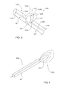
- Fig. 5 shows a medical device 400 according to yet another example of the invention.
- an elongated shaft (carrier) 14 is separable into two sections 14a and 14b, which remain connected to each other by a wire or shaft 430.
- a treatment tool 316 located inside the carrier 14 has a body shaft 22 carrying at its distal end 22A excision elements 320. The latter may or may not be integral with the body shaft 22.
- the treatment tool shaft 22 is advanced inside the shaft 14 until its distal end 22A reaches the distal end of the section 14A. Excision elements 220 are then deployed so as to excise an intact tissue portion.
- FIG. 6 shows a medical device 500 according to yet another example of the invention.
- peripheral slots 310 are provided in the shaft/carrier 14 being interspaced between tissue characterization sensors.
- a treatment tool 416 has a body shaft 22 carrying at its distal end excision elements 420. The latter may or may not be integral with the body shaft 22.
- a number of excision elements 320 corresponds to the number of the slots 310.
- the treatment tool 416 is advanced inside the shaft 14 until its distal end is positioned at a specific slot 310 location.
- the distal end of the treatment tool shaft 22 has a tapered/angled ending portion 330. This ending portion allows for controlling an angle at which the excision elements 420 is extended from the shaft 14 into tissue.
- the excision elements 420 are pre-bent so that when extended they close back on the shaft 14, thus cutting the tissue portion adjacent to the shaft 14. Additionally, the excision elements 420 may be connected at their ends by wires, or other flexible connection. This connection can be manipulated to induce the contraction of the excision elements 420 towards shaft 14, to facilitate cutting of the tissue portion adjacent to the shaft 14.
- the device may be rotated, manually or mechanically, to assist in completer tissue treatment (e.g. cutting and removal).
- the present invention provides a novel medical device capable of precisely located a tissue volume to be treated (removed), and also provides for treating (removing) the tissue by an integral medical device.
Abstract
Description
- This invention relates to medical devices and methods for use in tissue characterization and treatment.
- Techniques for in situ identifying abnormal (e.g. tumorous) cells in a biological tissue are generally known. Such techniques include those utilizing determination of the electrical properties of a tissue, for example, by determination of electrical impedance or dielectric constants. Some kinds of tumors can be identified by determining differences in the measured electrical properties of the tissue. The identified and located region of abnormal tissue can then be treated and/or removed from the body
- Various types of tissue characterization sensor and its integration with a tissue treatment/removal tool are described in the following patent publications, all assigned to the assignee of the present application:
US2003138378 ,WO2006103665 ,WO 2007015255 ,US6813515 andUS7184824 . - Also, various techniques are known for removing a certain tissue specimen from a tissue mass. These techniques are disclosed for example in
US 6,689,145 andUS 7,122,011 . - There is a need in the art to facilitate precise location and determination of a volume of a tissue specimen (e.g. abnormal tissues) to be treated (e.g. removed). Also, there is need in the art for a tissue treatment technique capable of adjusting a treatment volume to the determined volume of the abnormal tissue specimen.
- The present invention solves the above problems by providing a novel medical device for use in tissue characterization and treatment. The device comprises a tissue characterization probe comprising an elongated carrier for carrying an array of tissue characterization sensors arranged in a spaced-apart relationship at least along an axis of said carrier. During the progression of the probe through a tissue mass, signals from the tissue characterization sensors are used for locating and determining a dimension of an abnormal tissue specimen inside the tissue mass. This enables consequent treatment of the abnormal tissue specimen by a treatment tool.
- In preferred embodiment of the invention, the treatment tool is mounted on the characterization probe carrier. The treatment tool may be configured for carrying out at least one of the following biopsy, cutting, delivering physical treatment, delivering treatment medication, diagnostics.
- Preferably, the treatment tool is selectively shiftable between its inoperative position being located substantially entirely inside the carrier and its operative position projecting by its at least one tissue treating portion towards outside the carrier. In preferred embodiments of the invention, the dimension of the tissue treating portion(s) projectable from the carrier, and possibly also location of the tissue treating portion(s) with respect to the carrier can be controllably varied.
- In some embodiments of the invention, the probe carrier is formed with a guiding cutting tool, to facilitate insertion of the probe to a targeted location in the tissue. Also, in some embodiments of the invention, a marker may be left in the body, at the location of the treated (removed) tissue.
- The invention also provides a novel method for use in tissue characterization and treatment. A tissue mass is scanned with an array of tissue characterization sensors arranged in a spaced-apart relationship along a scanning axis, and signals from the sensors are detected and analyzed while scanning locate and determine a dimension of an abnormal tissue specimen inside said tissue mass that is to be treated during progression of the array through the tissue mass.
- Additionally, the invention provides a system for use in tissue characterization and treatment. The system comprises a medical device and a control unit connectable to the medical device. The latter is configured as described above, namely comprises a tissue characterization probe having a carrier on which an array of tissue characterization sensors is mounted with the sensors being arranged in a spaced-apart relationship at least along an elongated axis of the carrier. The control unit is configured for receiving and analyzing tissue characterizing signals from each of all the sensors and utilizing data indicative of the respective sensors' location, for determining a dimension of an abnormal tissue specimen.
- In order to understand the invention and to see how it may be carried out in practice, embodiments will now be described, by way of non-limiting example only, with reference to the accompanying drawings, in which:
-
Fig. 1 is a schematic illustration of a medical device of the present invention; and -
Figs. 2 to 6 show five examples, respectively, of the device configuration for both the tissue characterization and removal of a tissue specimen. - Referring to
Fig. 1 , there is schematically illustrated a medical device, generally designated 10, according to an embodiment of the invention. Thedevice 10 is configured for use in tissue characterization and treatment, and includes atissue characterization probe 12 carried by anelongated shaft 14, which has distal andproximal ends control handle 15 at itsproximal end 14B. Thetissue characterization probe 12 includes an array of tissue characterization sensors, eight such sensors S1-S8 being shown in the present example. - The tissue characterization sensor array may include one or more of optical, radiofrequency (RF), microwave (MW), electrical, magnetic, temperature, elastic, biological, chemical, radioactive-emission, and mechanical sensors of any known type. The construction and operation of the tissue characterization sensor does not form part of the present invention, and therefore need not be specifically described. For example, sensors described in the above indicated patent publications assigned to the assignee of the present application may be used.
- The sensors S1-S8 are arranged in a spaced-apart relationship along a longitudinal axis LA of the
carrier 14, and may be arranged in one- or two dimensional array. For example, the sensor array may include, in addition to a group of sensors arranged in one-dimensional array, sensors arranged in a spaced-apart manner along a circumferential region of the carrier. The sensor array gives, in real time, indication about the nature of tissue along thecarrier 14. - The sensors are spaced along the axis LA from one another a known distance, which may or may not be equal for all the sensors in the array. The known relative locations of the sensors along the
carrier 12 allows for identifying corresponding locations in a tissue mass when the probe is progressing through the tissue mass (i.e. scans the tissue) based on signals received from the sensors. In this connection, themedical device 10 is associated with anappropriate control system 19 configured for receiving and analyzing the signals generated by the sensors. It should be understood that connection between the sensors and the control unit is shown in the figure schematically, and in case wired connection is used such wires would extend inside theshaft 14 and exit at theproximal end 14B. - The control system may be an external system connectable (via wires or wireless signal transmission) to the sensors, or may be a constructional part of the probe itself. The control system, based on the analysis of the received signals, operates for determining a location of the margins of an abnormal tissue region inside the examined tissue mass and generating output data indicative of a dimension of the abnormal tissue region. This allows for consequent treatment of the abnormal tissue region by an appropriate treatment tool.
- The control system preferably includes a graphical user interface (GUI) 19A, and is configured for presenting information related to the signals received from each of the sensors. This information provides the operator with information regarding the tissue type at the locations of the sensors. The information presented on the GUI may assist the operator in analyzing the location and extent of the tissue to be treated.
- Generally, the treatment tool may be configured for carrying out one or more of the following: biopsy, cutting, delivering physical treatment, delivering treatment medication, diagnostics. More specifically, the present invention is used for removal of an intact tissue specimen (abnormal tissue) and is therefore described below with respect to this specific but not limiting example.
- Preferably, the
probe 12 also carries a treatment tool, e.g. a cutting tool. This is implemented by configuring the probe such that the treatment tool can be selectively shiftable between its inoperative position, when it is located substantially entirely inside thecarrier 14, and its operative positions when its one or more excision elements (constituting one or more tissue treating elements) project(s) from the carrier. - In some examples of the invention, the selective projection of the excision element is achieved by using the treatment tool of a kind known in the art, where the excision element projects from the carrier body through an opening made along the body portion while moving with respect to the carrier along an axis inclines with respect to the axis LA. In some other examples, the excision element projects from the carrier (e.g. from its distal end) while moving with respect to the carrier substantially along the axis LA. Such configurations are also generally known in the art. The treatment tool may be configured with a removed tissue collecting unit, which may or may not be selectively projectable from the probe.
- According to the invention, the medical device is configured such that a dimension of the excision element part projecting from the carrier can be controllably adjusted (varied) in accordance with the determined dimension of the abnormal tissue margins, thereby adjusting the excision volume. Preferably, the excision element is configured for both cutting the tissue and collecting the tissue being cut.
- The following are some specific but not limiting examples of the configuration of the device of the present invention. The same reference numbers are used for identifying components that are common in all the examples.
-
Fig. 2 shows amedical device 100 for removal of an intact tissue specimen. Thedevice 100 includes an elongated shaft/carrier 14 on which sensors S1-S8 of atissue characterization probe 12 are mounted in spaced-apart locations, and a tissue cutting tool (generally, a treatment tool) 16 mounted on thecarrier 14. - The cutting
tool 16 has abody portion 22 located inside thecarrier 14, and anexcision element 20 projectable from thebody 22 through anopening 18 made in thecarrier 14 In the figure, theexcision element 20 is shown in its operative projecting state. The excision element has acutting edge 21, and may be configured to have a cup-like shape when in the projecting state, thereby enabling collection of tissue while being cut during the rotation of thecarrier 14 and thus of theexcision element 20. - The
excision element 20 extends between its first and second ends 20A and 20B which are attached to respective first and second locations on thetreatment tool body 22 and spaced-apart along the axis LA of thecarrier 14. The treatment tool is configured to enable a controllable change of the dimensions of theexcision element 20. In the present example, this is implemented by making thetreatment tool body 22 from two spacedmembers portion 21 projecting through thecarrier 14. - By controlling the location of the excision element distal and
proximal ends carrier 14, and thus controlling the excision volume, a user can perform optimal removal of a tissue specimen, for example during a breast biopsy procedure. Theentire excision element 20 may be movable along thebody 22. Thus, the excision volume is controlled by user by changing the location of theexcision element 20 along thecarrier 14 and changing a distance between the distal and proximal ends of the excision element. - In the above example, the tissue removal procedure is carried while rotating the
carrier 14. Such procedure can be performed while keeping the carrier position and rotating the treatment tool. This is exemplified inFig. 3 . Adevice 200 includes acarrier 114 formed by twoseparate parts treatment tool 16 inside thecarrier 114. Thetreatment tool 16 has abody part 22 formed by two spaced-apartmembers excision element 120 attached thereto by its distal andproximal ends excision element 120 has asemi-spherical surface 124 defining acutting edge 21. Thesurface 124 has two arc-like portions portions 124A becomes received by theother portion 124B. Also, thesurface 124 has twoparts portion 124C can be received byportion 124C. These movements allow for altering the excision volume when in the operative projecting state of theexcision element 120 and for shifting theelement 120 between its operative projecting position and its inoperative position being located inside thecarrier 14. Cutting is implemented while rotating thetool body 22 with respect to thecarrier 14. Also, this configuration allows for collecting the tissue specimen while being cut. -
Fig. 4 shows amedical device 300 according to yet another example of the invention. Here, a treatment tool 216 has abody shaft 22 carrying at its distal end anexcision element 220. The latter may or may not be integral with thebody shaft 22. The excision element has a closed-loop cutting edge 221 which is pre-bent at fabrication so as to deploy from its inoperative closed position when inside thecarrier 14 into an open ring-like shape when being projected from the carrier. Attached to thecutting edge 221 is a flexible tissue collecting unit. When the excision element is pushed (by user) out of thecarrier 14 through its distal end, it gradually passes through its different operative states being of a spoon-like shape of different dimensions. -
Fig. 5 shows amedical device 400 according to yet another example of the invention. Here, an elongated shaft (carrier) 14 is separable into two sections 14a and 14b, which remain connected to each other by a wire orshaft 430. Atreatment tool 316 located inside thecarrier 14 has abody shaft 22 carrying at itsdistal end 22A excision elements 320. The latter may or may not be integral with thebody shaft 22. Thetreatment tool shaft 22 is advanced inside theshaft 14 until itsdistal end 22A reaches the distal end of thesection 14A.Excision elements 220 are then deployed so as to excise an intact tissue portion. -
Fig. 6 shows amedical device 500 according to yet another example of the invention. Here,peripheral slots 310 are provided in the shaft/carrier 14 being interspaced between tissue characterization sensors. At each location along theshaft 14 there may be 2-8 peripheral slots. Atreatment tool 416 has abody shaft 22 carrying at its distalend excision elements 420. The latter may or may not be integral with thebody shaft 22. A number ofexcision elements 320 corresponds to the number of theslots 310. Thetreatment tool 416 is advanced inside theshaft 14 until its distal end is positioned at aspecific slot 310 location. The distal end of thetreatment tool shaft 22 has a tapered/angled endingportion 330. This ending portion allows for controlling an angle at which theexcision elements 420 is extended from theshaft 14 into tissue. Theexcision elements 420 are pre-bent so that when extended they close back on theshaft 14, thus cutting the tissue portion adjacent to theshaft 14. Additionally, theexcision elements 420 may be connected at their ends by wires, or other flexible connection. This connection can be manipulated to induce the contraction of theexcision elements 420 towardsshaft 14, to facilitate cutting of the tissue portion adjacent to theshaft 14. - It should be understood that in all the above-exemplified embodiments the device may be rotated, manually or mechanically, to assist in completer tissue treatment (e.g. cutting and removal).
- Thus, the present invention provides a novel medical device capable of precisely located a tissue volume to be treated (removed), and also provides for treating (removing) the tissue by an integral medical device.
Claims (16)
- A medical device for use in tissue characterization and treatment, the device comprising a tissue characterization probe comprising:an elongated carrier having a longitudinal axis;an array of tissue characterization sensors mounted on said carrier being arranged in a spaced-apart relationship at least along said longitudinal axis of said carrier, thereby enabling scan of a tissue mass by each of said sensors during progression of the probe through the tissue mass along said longitudinal axis, and enabling to locate an abnormal tissue specimen inside said tissue mass and determine a dimension of the abnormal tissue specimen based on characterization signals generated by the sensors; anda treatment tool comprising at least one tissue treating portion and being configured and operable to be selectively shiftable between its inoperative position being located substantially entirely inside the carrier and its operative position projecting by at least a portion of said at least one tissue treating portion towards outside the carrier, thereby enabling selective treatment of the abnormal tissue specimen, said at least one tissue treating portion comprising a tissue excision element.
- A device according to claim 1, wherein the treatment tool comprises a body, said at least one tissue excision element being projectable from said body.
- A device according of claim 1 or 2, wherein the treatment tool is rotatable about the longitudinal axis of the carrier.
- A device according to claim 2 or 3, wherein the excision element extends between its first and second ends which are attached to respective first and second locations on the treatment tool body and are spaced-apart from one another along the longitudinal axis of said carrier.
- A device according to claim 4, wherein the treatment tool body extends along at least a part of said carrier thereinside such that at least one of the first and second locations is movable towards and away from the other along said axis of the carrier to thereby adjust the dimension of a portion of the excision element projecting from the carrier.
- A device according to any one of claims 3 to 5, wherein the body of the treatment tool has an elongated member extending along at least a part of said carrier and being rotatable about the longitudinal axis of the carrier, the at least one excision element being projectable from said body, the excision element being attached by its opposite edges to said elongated member allowing variation of a dimension of the excision element along the longitudinal axis of the carrier, and being rotatable with the rotation of the elongated member.
- A device according to Claim 3, wherein the treatment tool body extends along the carrier and the excision element is located at a distal end of the treatment tool body being selectively projectable from the carrier by the portion thereof through the distal end of the carrier.
- A device according to Claim 7, wherein the excision element has a tissue cutting edge which is pre-bent at fabrication into a certain closed-loop shape, such that when the excision element is totally inside the carrier the tissue cutting portion is in its inoperative folded position and while being projecting from the carrier it is gradually expanding into its bent spoon-like state, an extent of projection defining the dimension of the bent tissue cutting portion.
- A device according to claim 7 or 8, wherein the excision element when in the projecting state thereof has a cup-like shape, thereby enabling collection of tissue while being cut during the rotation of the carrier and thus of the excision element.
- A device according to Claim 1, wherein the carrier is formed with slots interspaced between the tissue characterization sensors, such that at each location along the carrier there are at least two peripheral slots.
- A device according to Claim 10, wherein the treatment tool body extends along at least a part of the carrier and is movable with respect to the carrier along said axis.
- A device according to claim 11, having one of the following configurations:(i) the treatment tool body carries at its distal end a number of excision elements corresponding to the number of the slots, said excision elements being pre-bent such that when they extend through the slots they close back towards the carrier, thus cutting a tissue portion adjacent to the carrier;(ii) the excision elements are connected at their ends by flexible connectors, manipulation of the connectors allows for inducing contraction of the excision elements towards the carrier thereby facilitating cutting of the tissue portion adjacent to the carrier.
- A device according to Claim 11, wherein the excision elements are connected at their ends by flexible connectors, manipulation of the connectors allows for inducing contraction of the excision elements towards the carrier thereby facilitate cutting of the tissue portion adjacent to the carrier, the distal end of the treatment tool body having a tapered ending portion, thereby allowing for controlling an angle at which the excision element are extended from the carrier into tissue.
- A device according to any one of Claims 1 to 13, wherein the treatment tool is configured for carrying out at least one of the following: biopsy, cutting, delivering physical treatment, delivering treatment medication, diagnostics.
- A device according to any one of the preceding claims, wherein said excision element has a tissue collecting unit for collecting tissue being removed, said tissue collecting unit being of variable dimensions.
- A medical device for use in tissue characterization and treatment, the device comprising a tissue characterization probe comprising:an elongated carrier having a longitudinal axis;an array of tissue characterization sensors mounted on said carrier being arranged in a spaced-apart relationship at least along said longitudinal axis of said carrier, thereby enabling scan of a tissue mass by each of said sensors during progression of the probe through the tissue mass along said longitudinal axis, and enabling to locate an abnormal tissue specimen inside said tissue mass and determine a dimension of the abnormal tissue specimen based on characterization signals generated by the sensors; anda treatment tool comprising a body having an elongated member extending along at least a part of said carrier and being rotatable about the longitudinal axis of the carrier, and at least one excision element projectable from said body, the excision element being attached by its opposite edges to said elongated member allowing variation of a dimension of the excision element along the longitudinal axis of the carrier, and being rotatable with the rotation of the elongated member.
Applications Claiming Priority (2)
| Application Number | Priority Date | Filing Date | Title |
|---|---|---|---|
| US95008107P | 2007-07-16 | 2007-07-16 | |
| EP08776603.6A EP2178443B1 (en) | 2007-07-16 | 2008-07-13 | Medical device for use in tissue characterization and treatment |
Related Parent Applications (3)
| Application Number | Title | Priority Date | Filing Date |
|---|---|---|---|
| EP08776603.6 Division | 2008-07-13 | ||
| WOPCT/IL2008/000965 Previously-Filed-Application | 2008-07-13 | ||
| EP08776603.6A Division-Into EP2178443B1 (en) | 2007-07-16 | 2008-07-13 | Medical device for use in tissue characterization and treatment |
Publications (2)
| Publication Number | Publication Date |
|---|---|
| EP2535006A2 true EP2535006A2 (en) | 2012-12-19 |
| EP2535006A3 EP2535006A3 (en) | 2013-02-27 |
Family
ID=39870512
Family Applications (2)
| Application Number | Title | Priority Date | Filing Date |
|---|---|---|---|
| EP08776603.6A Active EP2178443B1 (en) | 2007-07-16 | 2008-07-13 | Medical device for use in tissue characterization and treatment |
| EP12168882A Withdrawn EP2535006A3 (en) | 2007-07-16 | 2008-07-13 | Medical device for tissue characterization and treatment |
Family Applications Before (1)
| Application Number | Title | Priority Date | Filing Date |
|---|---|---|---|
| EP08776603.6A Active EP2178443B1 (en) | 2007-07-16 | 2008-07-13 | Medical device for use in tissue characterization and treatment |
Country Status (4)
| Country | Link |
|---|---|
| US (1) | US9301734B2 (en) |
| EP (2) | EP2178443B1 (en) |
| ES (1) | ES2547018T3 (en) |
| WO (1) | WO2009010960A2 (en) |
Families Citing this family (11)
| Publication number | Priority date | Publication date | Assignee | Title |
|---|---|---|---|---|
| EP2178443B1 (en) | 2007-07-16 | 2015-07-08 | Dune Medical Devices Ltd. | Medical device for use in tissue characterization and treatment |
| US9757098B2 (en) | 2007-07-16 | 2017-09-12 | Dune Medical Devices Ltd. | Medical device and method for use in tissue characterization and treatment |
| US9999353B2 (en) | 2007-07-16 | 2018-06-19 | Dune Medical Devices Ltd. | Medical device and method for use in tissue characterization and treatment |
| US9901362B2 (en) | 2007-07-16 | 2018-02-27 | Dune Medical Devices Ltd. | Medical device and method for use in tissue characterization and treatment |
| WO2011016034A2 (en) | 2009-08-03 | 2011-02-10 | Dune Medical Devices Ltd. | Surgical tool |
| CN102573622B (en) | 2009-08-03 | 2016-01-27 | 沙丘医疗设备有限公司 | For the electromagnetic transducer measured experimenter |
| EP2872046B1 (en) * | 2012-07-12 | 2019-05-08 | Dune Medical Devices Ltd. | Medical device for use in tissue characterization and treatment |
| JP6815998B2 (en) | 2014-12-03 | 2021-01-20 | パブメド インク. | Systems and methods for percutaneous division of fibrous structures |
| EP3292822A3 (en) | 2016-08-15 | 2018-05-23 | Dune Medical Devices Ltd. | Biopsy device |
| US20180049728A1 (en) * | 2016-08-22 | 2018-02-22 | The Charles Stark Draper Laboratory, Inc. | Instrumented biopsy probe |
| US11071601B2 (en) * | 2019-11-11 | 2021-07-27 | Procept Biorobotics Corporation | Surgical probes for tissue resection with robotic arms |
Citations (6)
| Publication number | Priority date | Publication date | Assignee | Title |
|---|---|---|---|---|
| US20030138378A1 (en) | 2001-11-19 | 2003-07-24 | Dune Medical Devices Ltd. | Method and apparatus for examining tissue for predefined target cells, particularly cancerous cells, and a probe useful in such method and apparatus |
| US6689145B2 (en) | 1998-09-03 | 2004-02-10 | Rubicor Medical, Inc. | Excisional biopsy devices and methods |
| US6813515B2 (en) | 2002-01-04 | 2004-11-02 | Dune Medical Devices Ltd. | Method and system for examining tissue according to the dielectric properties thereof |
| WO2006103665A2 (en) | 2005-03-29 | 2006-10-05 | Dune Medical Devices Ltd. | Electromagnetic sensors for tissue characterization |
| US7122011B2 (en) | 2003-06-18 | 2006-10-17 | Rubicor Medical, Inc. | Methods and devices for cutting and collecting soft tissue |
| WO2007015255A2 (en) | 2005-08-04 | 2007-02-08 | Dune Medical Devices Ltd. | Tissue-characterization probe with effective sensor-to-tissue contact |
Family Cites Families (23)
| Publication number | Priority date | Publication date | Assignee | Title |
|---|---|---|---|---|
| US6120437A (en) * | 1988-07-22 | 2000-09-19 | Inbae Yoon | Methods for creating spaces at obstructed sites endoscopically and methods therefor |
| US5318023A (en) | 1991-04-03 | 1994-06-07 | Cedars-Sinai Medical Center | Apparatus and method of use for a photosensitizer enhanced fluorescence based biopsy needle |
| US6006755A (en) * | 1994-06-24 | 1999-12-28 | Edwards; Stuart D. | Method to detect and treat aberrant myoelectric activity |
| EP0888086B1 (en) * | 1996-02-15 | 2005-07-27 | Biosense Webster, Inc. | Excavation probe |
| US5827313A (en) | 1996-09-27 | 1998-10-27 | Boston Scientific Corporation | Device for controlled longitudinal movement of an operative element within a catheter sheath and method |
| US5846513B1 (en) * | 1997-07-08 | 2000-11-28 | Carewise Medical Products Corp | Tumor localization and removal system using penetratable detection probe and removal instrument |
| US6626903B2 (en) * | 1997-07-24 | 2003-09-30 | Rex Medical, L.P. | Surgical biopsy device |
| US6602204B2 (en) | 1998-02-10 | 2003-08-05 | Artemis Medical, Inc | Intraoperative tissue treatment methods |
| US6331166B1 (en) | 1998-03-03 | 2001-12-18 | Senorx, Inc. | Breast biopsy system and method |
| US6626899B2 (en) | 1999-06-25 | 2003-09-30 | Nidus Medical, Llc | Apparatus and methods for treating tissue |
| US6346649B1 (en) * | 1999-12-28 | 2002-02-12 | Basf Aktiengesellschaft | Process for the recovery and recycle of D-tartaric acid |
| AU5113401A (en) | 2000-03-31 | 2001-10-15 | Rita Medical Systems Inc | Tissue biopsy and treatment apparatus and method |
| US7201722B2 (en) | 2000-04-18 | 2007-04-10 | Allegiance Corporation | Bone biopsy instrument having improved sample retention |
| US6419635B1 (en) * | 2000-08-11 | 2002-07-16 | General Electric Compsany | In situ tumor temperature profile measuring probe and method |
| US6419640B1 (en) * | 2000-10-03 | 2002-07-16 | Thomas V. Taylor | Multiple-specimen, endoscopic biopsy forceps |
| US6832111B2 (en) * | 2001-07-06 | 2004-12-14 | Hosheng Tu | Device for tumor diagnosis and methods thereof |
| US6585734B2 (en) * | 2001-09-17 | 2003-07-01 | Melvin Levinson | Tissue cutting and retrieval device and method |
| EP1720448A1 (en) | 2004-02-24 | 2006-11-15 | Wisconsin Alumni Research Foundation | Side-firing probe for performing optical spectroscopy during core needle biopsy |
| US20100222647A1 (en) | 2006-01-18 | 2010-09-02 | Dune Medical Devices Ltd. | System and method for analysis and treatment of a body tissue |
| EP2178443B1 (en) | 2007-07-16 | 2015-07-08 | Dune Medical Devices Ltd. | Medical device for use in tissue characterization and treatment |
| US8413582B1 (en) | 2009-03-24 | 2013-04-09 | Microfabrica Inc. | Linear escapements, methods for making, and use |
| CN102573622B (en) | 2009-08-03 | 2016-01-27 | 沙丘医疗设备有限公司 | For the electromagnetic transducer measured experimenter |
| AU2010322460B2 (en) | 2009-11-17 | 2015-05-28 | Harvard Apparatus Regenerative Technology, Inc. | Bioreactors, systems, and methods for producing and/or analyzing organs |
-
2008
- 2008-07-13 EP EP08776603.6A patent/EP2178443B1/en active Active
- 2008-07-13 ES ES08776603.6T patent/ES2547018T3/en active Active
- 2008-07-13 WO PCT/IL2008/000965 patent/WO2009010960A2/en active Application Filing
- 2008-07-13 EP EP12168882A patent/EP2535006A3/en not_active Withdrawn
- 2008-07-13 US US12/663,923 patent/US9301734B2/en active Active
Patent Citations (7)
| Publication number | Priority date | Publication date | Assignee | Title |
|---|---|---|---|---|
| US6689145B2 (en) | 1998-09-03 | 2004-02-10 | Rubicor Medical, Inc. | Excisional biopsy devices and methods |
| US20030138378A1 (en) | 2001-11-19 | 2003-07-24 | Dune Medical Devices Ltd. | Method and apparatus for examining tissue for predefined target cells, particularly cancerous cells, and a probe useful in such method and apparatus |
| US6813515B2 (en) | 2002-01-04 | 2004-11-02 | Dune Medical Devices Ltd. | Method and system for examining tissue according to the dielectric properties thereof |
| US7184824B2 (en) | 2002-01-04 | 2007-02-27 | Dune Medical Devices Ltd. | Method and system for examining tissue according to the dielectric properties thereof |
| US7122011B2 (en) | 2003-06-18 | 2006-10-17 | Rubicor Medical, Inc. | Methods and devices for cutting and collecting soft tissue |
| WO2006103665A2 (en) | 2005-03-29 | 2006-10-05 | Dune Medical Devices Ltd. | Electromagnetic sensors for tissue characterization |
| WO2007015255A2 (en) | 2005-08-04 | 2007-02-08 | Dune Medical Devices Ltd. | Tissue-characterization probe with effective sensor-to-tissue contact |
Also Published As
| Publication number | Publication date |
|---|---|
| US20100168611A1 (en) | 2010-07-01 |
| ES2547018T3 (en) | 2015-09-30 |
| WO2009010960A3 (en) | 2009-05-07 |
| EP2178443A2 (en) | 2010-04-28 |
| EP2178443B1 (en) | 2015-07-08 |
| US9301734B2 (en) | 2016-04-05 |
| EP2535006A3 (en) | 2013-02-27 |
| WO2009010960A2 (en) | 2009-01-22 |
Similar Documents
| Publication | Publication Date | Title |
|---|---|---|
| EP2535006A2 (en) | Medical device for tissue characterization and treatment | |
| EP1432360B1 (en) | Devices for tissue severing and removal | |
| JP5639593B2 (en) | Real-time pathological diagnosis | |
| US7229439B2 (en) | Apparatus and method for accessing a body site | |
| US6454727B1 (en) | Tissue acquisition system and method of use | |
| US20100280409A1 (en) | Real-time pathology | |
| US9757098B2 (en) | Medical device and method for use in tissue characterization and treatment | |
| JP2016512458A (en) | Ablation device and related methods of use | |
| US9999353B2 (en) | Medical device and method for use in tissue characterization and treatment | |
| US20130072815A1 (en) | Medical device and method for use in tissue characterization and treatment | |
| KR102494673B1 (en) | Apparatus and Method for Cutting and Retrieving Breast Specimen | |
| EP2872046B1 (en) | Medical device for use in tissue characterization and treatment | |
| JP6404450B2 (en) | Equipment with scooper core needle |
Legal Events
| Date | Code | Title | Description |
|---|---|---|---|
| PUAI | Public reference made under article 153(3) epc to a published international application that has entered the european phase |
Free format text: ORIGINAL CODE: 0009012 |
|
| AC | Divisional application: reference to earlier application |
Ref document number: 2178443 Country of ref document: EP Kind code of ref document: P |
|
| AK | Designated contracting states |
Kind code of ref document: A2 Designated state(s): AT BE BG CH CY CZ DE DK EE ES FI FR GB GR HR HU IE IS IT LI LT LU LV MC MT NL NO PL PT RO SE SI SK TR |
|
| RIN1 | Information on inventor provided before grant (corrected) |
Inventor name: COHEN, GIL Inventor name: HASHIMSHONY,, DAN |
|
| PUAL | Search report despatched |
Free format text: ORIGINAL CODE: 0009013 |
|
| AK | Designated contracting states |
Kind code of ref document: A3 Designated state(s): AT BE BG CH CY CZ DE DK EE ES FI FR GB GR HR HU IE IS IT LI LT LU LV MC MT NL NO PL PT RO SE SI SK TR |
|
| RIC1 | Information provided on ipc code assigned before grant |
Ipc: A61B 10/02 20060101AFI20130118BHEP Ipc: A61B 5/00 20060101ALN20130118BHEP Ipc: A61B 19/00 20060101ALN20130118BHEP Ipc: A61B 17/00 20060101ALN20130118BHEP |
|
| STAA | Information on the status of an ep patent application or granted ep patent |
Free format text: STATUS: THE APPLICATION IS DEEMED TO BE WITHDRAWN |
|
| 18D | Application deemed to be withdrawn |
Effective date: 20130828 |