EP2514383A1 - System and method for UV tacking an implant - Google Patents
System and method for UV tacking an implant Download PDFInfo
- Publication number
- EP2514383A1 EP2514383A1 EP20120163852 EP12163852A EP2514383A1 EP 2514383 A1 EP2514383 A1 EP 2514383A1 EP 20120163852 EP20120163852 EP 20120163852 EP 12163852 A EP12163852 A EP 12163852A EP 2514383 A1 EP2514383 A1 EP 2514383A1
- Authority
- EP
- European Patent Office
- Prior art keywords
- mesh
- light
- surgical instrument
- implant
- end effector
- Prior art date
- Legal status (The legal status is an assumption and is not a legal conclusion. Google has not performed a legal analysis and makes no representation as to the accuracy of the status listed.)
- Granted
Links
Images


Classifications
-
- A—HUMAN NECESSITIES
- A61—MEDICAL OR VETERINARY SCIENCE; HYGIENE
- A61F—FILTERS IMPLANTABLE INTO BLOOD VESSELS; PROSTHESES; DEVICES PROVIDING PATENCY TO, OR PREVENTING COLLAPSING OF, TUBULAR STRUCTURES OF THE BODY, e.g. STENTS; ORTHOPAEDIC, NURSING OR CONTRACEPTIVE DEVICES; FOMENTATION; TREATMENT OR PROTECTION OF EYES OR EARS; BANDAGES, DRESSINGS OR ABSORBENT PADS; FIRST-AID KITS
- A61F2/00—Filters implantable into blood vessels; Prostheses, i.e. artificial substitutes or replacements for parts of the body; Appliances for connecting them with the body; Devices providing patency to, or preventing collapsing of, tubular structures of the body, e.g. stents
- A61F2/0063—Implantable repair or support meshes, e.g. hernia meshes
-
- A—HUMAN NECESSITIES
- A61—MEDICAL OR VETERINARY SCIENCE; HYGIENE
- A61B—DIAGNOSIS; SURGERY; IDENTIFICATION
- A61B17/00—Surgical instruments, devices or methods, e.g. tourniquets
- A61B17/28—Surgical forceps
- A61B17/29—Forceps for use in minimally invasive surgery
-
- A—HUMAN NECESSITIES
- A61—MEDICAL OR VETERINARY SCIENCE; HYGIENE
- A61B—DIAGNOSIS; SURGERY; IDENTIFICATION
- A61B18/00—Surgical instruments, devices or methods for transferring non-mechanical forms of energy to or from the body
- A61B18/04—Surgical instruments, devices or methods for transferring non-mechanical forms of energy to or from the body by heating
- A61B18/12—Surgical instruments, devices or methods for transferring non-mechanical forms of energy to or from the body by heating by passing a current through the tissue to be heated, e.g. high-frequency current
- A61B18/14—Probes or electrodes therefor
- A61B18/1442—Probes having pivoting end effectors, e.g. forceps
- A61B18/1445—Probes having pivoting end effectors, e.g. forceps at the distal end of a shaft, e.g. forceps or scissors at the end of a rigid rod
-
- A—HUMAN NECESSITIES
- A61—MEDICAL OR VETERINARY SCIENCE; HYGIENE
- A61B—DIAGNOSIS; SURGERY; IDENTIFICATION
- A61B18/00—Surgical instruments, devices or methods for transferring non-mechanical forms of energy to or from the body
- A61B18/18—Surgical instruments, devices or methods for transferring non-mechanical forms of energy to or from the body by applying electromagnetic radiation, e.g. microwaves
-
- A—HUMAN NECESSITIES
- A61—MEDICAL OR VETERINARY SCIENCE; HYGIENE
- A61B—DIAGNOSIS; SURGERY; IDENTIFICATION
- A61B18/00—Surgical instruments, devices or methods for transferring non-mechanical forms of energy to or from the body
- A61B18/04—Surgical instruments, devices or methods for transferring non-mechanical forms of energy to or from the body by heating
- A61B18/12—Surgical instruments, devices or methods for transferring non-mechanical forms of energy to or from the body by heating by passing a current through the tissue to be heated, e.g. high-frequency current
- A61B18/14—Probes or electrodes therefor
- A61B18/1442—Probes having pivoting end effectors, e.g. forceps
-
- A—HUMAN NECESSITIES
- A61—MEDICAL OR VETERINARY SCIENCE; HYGIENE
- A61B—DIAGNOSIS; SURGERY; IDENTIFICATION
- A61B17/00—Surgical instruments, devices or methods, e.g. tourniquets
- A61B17/00491—Surgical glue applicators
- A61B2017/005—Surgical glue applicators hardenable using external energy source, e.g. laser, ultrasound
-
- A—HUMAN NECESSITIES
- A61—MEDICAL OR VETERINARY SCIENCE; HYGIENE
- A61B—DIAGNOSIS; SURGERY; IDENTIFICATION
- A61B17/00—Surgical instruments, devices or methods, e.g. tourniquets
- A61B17/28—Surgical forceps
- A61B17/29—Forceps for use in minimally invasive surgery
- A61B2017/2926—Details of heads or jaws
-
- A—HUMAN NECESSITIES
- A61—MEDICAL OR VETERINARY SCIENCE; HYGIENE
- A61B—DIAGNOSIS; SURGERY; IDENTIFICATION
- A61B18/00—Surgical instruments, devices or methods for transferring non-mechanical forms of energy to or from the body
- A61B18/18—Surgical instruments, devices or methods for transferring non-mechanical forms of energy to or from the body by applying electromagnetic radiation, e.g. microwaves
- A61B2018/1807—Surgical instruments, devices or methods for transferring non-mechanical forms of energy to or from the body by applying electromagnetic radiation, e.g. microwaves using light other than laser radiation
-
- A—HUMAN NECESSITIES
- A61—MEDICAL OR VETERINARY SCIENCE; HYGIENE
- A61F—FILTERS IMPLANTABLE INTO BLOOD VESSELS; PROSTHESES; DEVICES PROVIDING PATENCY TO, OR PREVENTING COLLAPSING OF, TUBULAR STRUCTURES OF THE BODY, e.g. STENTS; ORTHOPAEDIC, NURSING OR CONTRACEPTIVE DEVICES; FOMENTATION; TREATMENT OR PROTECTION OF EYES OR EARS; BANDAGES, DRESSINGS OR ABSORBENT PADS; FIRST-AID KITS
- A61F2/00—Filters implantable into blood vessels; Prostheses, i.e. artificial substitutes or replacements for parts of the body; Appliances for connecting them with the body; Devices providing patency to, or preventing collapsing of, tubular structures of the body, e.g. stents
- A61F2/0063—Implantable repair or support meshes, e.g. hernia meshes
- A61F2002/0072—Delivery tools therefor
-
- A—HUMAN NECESSITIES
- A61—MEDICAL OR VETERINARY SCIENCE; HYGIENE
- A61F—FILTERS IMPLANTABLE INTO BLOOD VESSELS; PROSTHESES; DEVICES PROVIDING PATENCY TO, OR PREVENTING COLLAPSING OF, TUBULAR STRUCTURES OF THE BODY, e.g. STENTS; ORTHOPAEDIC, NURSING OR CONTRACEPTIVE DEVICES; FOMENTATION; TREATMENT OR PROTECTION OF EYES OR EARS; BANDAGES, DRESSINGS OR ABSORBENT PADS; FIRST-AID KITS
- A61F2210/00—Particular material properties of prostheses classified in groups A61F2/00 - A61F2/26 or A61F2/82 or A61F9/00 or A61F11/00 or subgroups thereof
- A61F2210/0085—Particular material properties of prostheses classified in groups A61F2/00 - A61F2/26 or A61F2/82 or A61F9/00 or A61F11/00 or subgroups thereof hardenable in situ, e.g. epoxy resins
-
- A—HUMAN NECESSITIES
- A61—MEDICAL OR VETERINARY SCIENCE; HYGIENE
- A61F—FILTERS IMPLANTABLE INTO BLOOD VESSELS; PROSTHESES; DEVICES PROVIDING PATENCY TO, OR PREVENTING COLLAPSING OF, TUBULAR STRUCTURES OF THE BODY, e.g. STENTS; ORTHOPAEDIC, NURSING OR CONTRACEPTIVE DEVICES; FOMENTATION; TREATMENT OR PROTECTION OF EYES OR EARS; BANDAGES, DRESSINGS OR ABSORBENT PADS; FIRST-AID KITS
- A61F2220/00—Fixations or connections for prostheses classified in groups A61F2/00 - A61F2/26 or A61F2/82 or A61F9/00 or A61F11/00 or subgroups thereof
- A61F2220/0008—Fixation appliances for connecting prostheses to the body
-
- A—HUMAN NECESSITIES
- A61—MEDICAL OR VETERINARY SCIENCE; HYGIENE
- A61F—FILTERS IMPLANTABLE INTO BLOOD VESSELS; PROSTHESES; DEVICES PROVIDING PATENCY TO, OR PREVENTING COLLAPSING OF, TUBULAR STRUCTURES OF THE BODY, e.g. STENTS; ORTHOPAEDIC, NURSING OR CONTRACEPTIVE DEVICES; FOMENTATION; TREATMENT OR PROTECTION OF EYES OR EARS; BANDAGES, DRESSINGS OR ABSORBENT PADS; FIRST-AID KITS
- A61F2220/00—Fixations or connections for prostheses classified in groups A61F2/00 - A61F2/26 or A61F2/82 or A61F9/00 or A61F11/00 or subgroups thereof
- A61F2220/0025—Connections or couplings between prosthetic parts, e.g. between modular parts; Connecting elements
- A61F2220/005—Connections or couplings between prosthetic parts, e.g. between modular parts; Connecting elements using adhesives
Abstract
Description
- The present application claims the benefit of and priority to
U.S. Provisional Application Serial No.61/478,154, filed on April 22, 2011 - The present disclosure relates to endoscopic surgical instruments. More particularly, the present disclosure relates to a system and method for ultraviolet (UV) tacking an implant via an endoscopic surgical instrument having a UV light source mechanism distally disposed.
- Surgical instruments which include a tool assembly mounted on a distal end of a body portion of the surgical instrument for articulation are well known. Typically, such surgical instruments include articulation control mechanisms, which allow an operator to remotely articulate the tool assembly in relation to the body portion of a surgical instrument to allow the operator to more easily access, operate on, and/or manipulate tissue.
- Such articulating tool assemblies have become desirable, especially in the endoscopic surgical procedures. In an endoscopic surgical procedure, the distal end of a surgical instrument is inserted through small incisions in the body to access a surgical site. Typically, an appropriately sized cannula, e.g., 5 mm, 10 mm, etc., is inserted through the body incision to provide a guide channel for accessing the surgical site. Because it is desirable to provide small body incisions, i.e., less scarring, reduced trauma to the patient, faster healing time, the tolerances between the surgical instrument and the inner diameter of the cannula are small.
- Conventional articulating tool tips have limited functionality mainly due to mechanical design limitations of actuating mechanisms. Thus, it is desirable to provide an articulating surgical instrument, which includes an articulation mechanism that would provide a wider range of functions for the articulation tip.
- Accordingly, an improved surgical instrument is provided. The surgical instrument includes a handle portion and a body portion extending distally from the handle portion and defining a longitudinal axis. The surgical instrument also includes a grasper disposed at a distal end of the body portion, the grasper including an ultraviolet (UV) light mechanism for performing UV tacking of an implant.
- In another exemplary embodiment, the grasper is an end effector assembly having a first jaw member and a second jaw member. The first and second jaw members are movable from a first position in spaced relation relative to one another to a second position where the first and second jaw members cooperate to grasp the implant therebetween.
- In another exemplary embodiment, the implant is a mesh having a UV reactive polymeric coating. The mesh is positioned between the first and second jaw members: (i) to be placed at a surgical site and (ii) to be exposed by a UV light emitted from the UV light mechanism such that the UV tacking of the mesh to the surgical site is performed. The mesh includes one or more tack regions each having a polymer coating embedded therein, the polymer coating being chemically induced by a UV light of the UV light mechanism.
- A mesh having a UV reactive polymeric coating suitable for some embodiments of the present invention is found in
U.S. Provisional Application Ser. No. 61/348896 filed on May 27 2010 - In another exemplary embodiment, tack regions may be a uniform coating of the mesh surface or may be distinct regions. In yet another exemplary embodiment, the tack regions are visually designated along a length of the mesh. In a further embodiment, the regions tacked by the instrument change color when subjected to UV light or pressure, indicating locations on the mesh that have been tacked.
- The UV light mechanism may be positioned on a non-grasping portion of the grasper. However, the UV light mechanism may be positioned on at least one grasping portion of the grasper.
- In yet another exemplary embodiment, the surgical instrument further includes at least one sensor adapted to continuously or intermittently monitor UV light emission from the UV light mechanism. Additionally, the surgical instrument may include a trigger mechanism positioned on the handle portion for selectively activating the UV light mechanism.
- In another exemplary embodiment, an improved surgical instrument assembly is provided. The surgical instrument assembly includes a handle portion and a body portion extending distally from the handle portion. The surgical instrument assembly also includes an end effector assembly disposed at a distal end of the body portion, the end effector assembly including a light source for tacking a mesh in position at a surgical site.
- In another exemplary embodiment a method of UV tacking a mesh at a surgical site is provided. The method includes the steps of providing a surgical instrument including an ultraviolet (UV) light mechanism for performing UV tacking of an implant; providing a mesh implant having a polymeric coating activated by UV light; endoscopically positioning the mesh over the surgical site; and selectively applying UV light emitted from the UV light source to the mesh to tack the mesh to the site The mesh may include a polymeric coating that is activated upon exposure from the UV light emitted from the UV light source.
- The accompanying drawings, which are incorporated in and constitute a part of this specification, illustrate embodiments of the disclosure and, together with a general description of the disclosure given above, and the detailed description of the embodiment(s) given below, serve to explain the principles of the disclosure, wherein:
-
FIG. 1A is a perspective view of a surgical instrument in accordance with the present disclosure; -
FIG. 1B is a perspective view of the end effector assembly of the surgical instrument ofFIG. 1A , illustrating one or more ultraviolet (UV) light sources on a non-grasping portion of the end effector assembly, in accordance with the present disclosure; -
FIG. 1C is a perspective view of the end effector assembly of the surgical instrument ofFIG. 1A , illustrating one or more UV light sources on grasping portions of the end effector assembly, in accordance with the present disclosure; -
FIG. 2A is a perspective view of another surgical stapling instrument in accordance with the present disclosure; -
FIG. 2B is a perspective view of the end effector assembly of the surgical instrument ofFIG. 2A , illustrating one or more UV light sources on a non-grasping portion of the end effector assembly, in accordance with the present disclosure; -
FIG. 2C is a perspective view of the end effector assembly of the surgical instrument ofFIG. 2A , illustrating one or more UV light sources on grasping portions of the end effector assembly, in accordance with the present disclosure; -
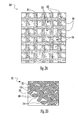
FIG. 3A is a perspective view of the mesh, in accordance with the present disclosure; -
FIG. 3B is a perspective cross-sectional view of the mesh ofFIG. 3A , in accordance with the present disclosure; -
FIG. 4A is a perspective view of the surgical instrument ofFIG. 1A grasping the mesh ofFIG. 3A , in order to apply UV light via the one or more UV light sources to the mesh, in accordance with the present disclosure; and -
FIG. 4B is a perspective view of the surgical instrument ofFIG. 2A grasping the mesh ofFIG. 3A , in order to apply UV light via the one or more UV light sources to the mesh, in accordance with the present disclosure. - Embodiments of the presently disclosed apparatus will now be described in detail with reference to the drawings, in which like reference numerals designate identical or corresponding elements in each of the several views. As used herein, the term "distal" refers to that portion of the tool, or component thereof which is further from the user while the term "proximal" refers to that portion of the tool or component thereof which is closer to the user.
- Referring to
FIGS. 1A-1C , a surgical system for use in a surgical procedure, e.g., a minimally invasive procedure is illustrated. -
FIG. 1A shows asurgical instrument 10 according to the present disclosure. More particularly,surgical instrument 10 generally includes a housing 21, a handle assembly 40, a rotating assembly 80, and a trigger assembly 70, which mutually cooperate with theend effector assembly 100 to grasp and treat tissue. Such a graspinginstrument 10 is further exemplified by laparoscopic grasping instruments such as Covidien order codes 173030, 174317, 174001 and 174233. - The
surgical instrument 10 also includes a shaft 12, which has adistal end 14 that mechanically engages theend effector assembly 100 and aproximal end 16 that mechanically engages the housing 21 proximate the rotating assembly 80. Handle assembly 40 includes a fixed handle 50 and amovable handle 42.Handle 42 moves relative to the fixed handle 50 to actuate theend effector assembly 100 and enable a user to grasp and manipulate tissue. - The
end effector assembly 100 includes opposingjaw members jaw members movable handle 42 to impart movement of thejaw members - The
surgical instrument 10 also includes a rotating assembly 80 mechanically associated with the shaft 12 and the drive assembly (not shown). Movement of the rotating assembly 80 imparts similar rotational movement to the shaft 12 which, in turn, rotates theend effector assembly 100. - As best seen with respect to
FIG. 1A , theend effector assembly 100 attaches to thedistal end 14 of shaft 12. Thejaw members pivot 160 from the open to closed positions upon relative reciprocation, i.e., longitudinal movement, of the drive assembly (not shown). It is envisioned that thesurgical instrument 10 may be designed such that it is fully or partially disposable depending upon a particular purpose or to achieve a particular result. For example,end effector assembly 100 may be selectively and releasably engageable with thedistal end 14 of the shaft 12 and/or theproximal end 16 of the shaft 12 may be selectively and releasably engageable with the housing 21 and handle assembly 40. In either of these two instances, thesurgical instrument 10 may be either partially disposable or reposable, such as where a new or differentend effector assembly 100 or endeffector assembly 100 and shaft 12 are used to selectively replace the oldend effector assembly 100 as needed. - Additionally,
FIG. 1A illustrates a UV light source 90 (or UV light mechanism) disposed at the distal end of thefirst jaw 110. TheUV light source 90 is better seen inFIGS. 1B and 1C , which illustrate theend effector assembly 100.FIG. 1B illustrates one or moreUV light sources 90 on thefirst jaw 110 and the second jaw 120 (i.e., the non-grasping portions of thejaws 110, 120).FIG. 1C illustrates one or moreUV light sources 90 on the grasping portions of thesecond jaw 120. One skilled in the art may contemplate using a number of different UV light sources on one jaw or on both jaws and may contemplate positioning such UV light sources on or about any desired portion(s) of theend effector assembly 100. - In operation, the
jaw members FIGS. 3A and 3B ). Thelight sources 90 positioned on the first andsecond jaws 110, 120 (seeFIG. 1B ) are triggered to emit UV light to activate an adhesive on the implant or mesh to permanently secure the implant or mesh to the incision of the surgical site. The adhesive may be a UV activated adhesive. Thus, thesurgical instrument 10 may perform a full cure to permanently attach or tack the implant or mesh by using theUV light source 90 to activate UV adhesive sprayed on the implant or mesh. A less than full cure for temporarily securing the implant may be achieved by applying a lower energy of UV light. - Energy is transmitted to the implant or mesh from one or more energy transmission devices such as a laser or lasers. In at least one embodiment, the laser is a UV laser, however in some alternative embodiments the laser may be an IR laser, diode laser, Coy , visible light, or any other form of laser device or combinations thereof. One skilled in the art may contemplate using a plurality of different forms of energy in order to tack the implant or mesh to the incision of the surgical site. For example, one skilled in the art may use thermal energy, microwave energy, chemical energy, and/or ultrasonic energy or a combination thereof.
- Referring to
FIG. 2A , a perspective view of anothersurgical stapling instrument 500 in accordance with the present disclosure is presented. - In
FIG. 2A ,surgical instrument 500 includes ahandle portion 510, abody portion 512, and a disposable loading unit ("DLU") 540.Handle portion 510 includes astationary handle 514 and a movable handle or trigger 516.Movable handle 516 is movable in relation tostationary handle 514 to advance a control rod 520 (not shown), which projects from the distal end ofbody portion 512. Alternately, other surgical instruments may be used withDLU 540 to perform endoscopic surgical procedures. Thesurgical instrument 500 also includes anarticulation mechanism 400 for articulating atool assembly 17 of theDLU 540. Thetool assembly 17 may include afirst jaw 520 and asecond jaw 522. -
DLU 540 includes atool assembly 17, aproximal body portion 200 and a mountingassembly 235.Body portion 200 has a proximal end adapted to releasably engage the distal end of asurgical instrument 500. Mountingassembly 235 is pivotally secured to a distal end ofbody portion 200 and is fixedly secured to a proximal end oftool assembly 17. Pivotal movement of mountingassembly 235 about an axis perpendicular to a longitudinal axis ofbody portion 200 effects articulation oftool assembly 17 between a non-articulated position in which the longitudinal axis oftool assembly 17 is aligned with the longitudinal axis ofbody portion 200 and an articulated position in which the longitudinal axis oftool assembly 17 is disposed at an angle to the longitudinal axis ofbody portion 200. - Additionally, the
surgical instrument 500 includes a UV light source 590 (or UV light mechanism) disposed at the distal end of thetool assembly 17. The UVlight source 590 is better seen inFIGS. 2B and 2C , which illustrate thetool assembly 17.FIG. 2B illustrates one or more UVlight sources 590 on the lower jaw (i.e., the non-grasping portion of the tool assembly 17).FIG. 2C illustrates one or more UVlight sources 590 on the grasping portions of thetool assembly 17. One skilled in the art may contemplate using a number of different UV light sources on one jaw or on both jaws and may contemplate positioning such UV light sources on or about any desired portion(s) of thetool assembly 17. - Referring to
FIGS. 2B and 2C , perspective views of thetool assembly 17 of thesurgical instrument 500 ofFIG. 2A , illustrating one or more UVlight sources 590 on a non-grasping portion and a grasping portion of thetool assembly 17, respectively, in accordance with the present disclosure is presented. - In operation, the
jaw members FIGS. 3A and 3B ). Thelight sources 590 positioned on the second jaw 520 (seeFIG. 2C ) are triggered to emit UV light to activate an adhesive on the implant or mesh to permanently secure the implant or mesh to the incision of the surgical site. The adhesive may be a UV activated adhesive. Thus, thesurgical instrument 500 may perform a full cure to permanently attach or tack the implant or mesh by using the UVlight source 590 to activate UV adhesive sprayed on the implant or mesh. - Referring to
FIG. 3A , a perspective view of themesh 310, in accordance with the present disclosure is presented, whereas referring toFIG. 3B a perspective cross-sectional view of themesh 310 ofFIG. 3A , in accordance with the present disclosure is presented. - The surgical mesh 310 (or implant) is suitable for surgical repair of hernias and other surgical procedures requiring reinforcement or repair of soft tissue, such as muscle or wall tissue defects, pelvic organ prolapse, and urinary incontinence, for example. The
mesh 310 of the present disclosure may be in the form of sheets, patches, slings, suspenders, and other implants and composite materials such as pledgets, buttresses, wound dressings, drug delivery devices, and the like. The presentsurgical mesh 310 may be implanted using open surgery or by a laparoscopic procedure. - The
surgical mesh 310 may be fabricated from monofilament and/ormultifilament yarns 312, which may be made of any suitable biocompatible material. Suitable materials from which themesh 310 may be made should have the following characteristics: sufficient tensile strength to support tissue; sufficiently inert to avoid foreign body reactions when retained in the body for long periods of time; easily sterilized to prevent the introduction of infection when themesh 310 is implanted in the body; and sufficiently strong to avoid tearing of portions thereof. - Referring now to
FIGS. 3A and 3B , themesh 310 is illustrated including aporous mesh substrate 311. Thesubstrate 311 may be formed from fibers, filaments, threads oryarns 312 defining a plurality ofpores 314 therebetween. Theyarns 312 of thesubstrate 311 may be made up of multiple filaments 338 (seeFIG. 3B ). Thepores 314 may include one or moreintra-pore films 316. Theintra-pore films 316 of the present disclosure are non-contiguous with respect to one another, with eachintra-pore film 316 being located in asingle pore 314 of theporous substrate 311. In embodiments, multipleintra-pore films 316 may also be formed within each of thepores 314 of thesubstrate 311. The term "non-contiguous" as used herein, is used to denote one ormore films 316 that are wholly contained within acorresponding pore 314 and are not in physical contact with anotherintra-pore film 316 of anyother pore 314, as compared to a conventional film-coated porous substrate in which the film stretches across multiple pores. Theintra-pore films 316 are solely contained within the pores of the substrate. The intra-pore film does not span across theyarns 312 of the substrate. Theintra-pore films 316 are non-contiguous and are not bridged together by applying a film over the entire substrate, but rather, theintra-pore films 316 are created at discrete locations, within the individual pores. - The
intra-pore films 316 may be formed at any plane within thepores 314 relative to the plane of thesubstrate 311 such that theintra-pore film 316 does not contact any adjacentintra-pore film 316. In embodiments, theintra-pore film 316 may be textured, smooth and/or porous. - In a preferred embodiment, the
yarns 312 may be sprayed with a UV polymer adhesive that is activated when aUV light source 90, 590 (seeFIGS. 1A-2C ) is placed in the proximity of theyarns 312 of themesh 310. - As illustrated in
FIG. 3A , not everypore 314 includes an intra-pore film. In certain embodiments, the pores including intra-pore films may be from about 10% to about 95% of the pores. In further embodiments, about 15% to about 90% of the pores of thesubstrate 311 include at least one intra-pore film. In other embodiments, from about 25% to about 75% of the pores of thesubstrate 311 include at least one intra-pore film. In other embodiments, all of the pores of thesubstrate 311 may include an intra-pore film. - The
substrate 311 may include at least a center and a periphery. In embodiments where less than 100% of the pores of thesubstrate 311 include intra-pore films, the location of the intra-pore films may be random or patterned. For example, the pores of thesubstrate 311 that include the intra-pore films may be solely disposed in the center of thesubstrate 311 or the pores that include the intra-pore films may be solely disposed on the periphery of the substrate. In embodiments, the location of intra-pore films may be varied (e.g., random, patterned, etc.) depending upon the intended use of thesubstrate 311. The intra-pore films may form a discontinuous layer covering intermittent portions of the surface of thesubstrate 311. In one example, the intra-pore films may form a discontinuous layer on the surface of thesubstrate 311, wherein the porosity of thesubstrate 311 is maintained by the discontinuous layer of the intra-pore films. - Each
intra-pore film 316 of asubstrate 311 may be made from the same materials or different materials. In particular, one or more of theintra-pore films 316 may be formed from one material, while one or more differentintra-pore films 316 may be formed from another material. Theintra-pore film 316 may be permanent (e.g., non-bioabsorbable), biodegradable, or may be formed from any suitable combination of natural, synthetic, biodegradable and non-biodegradable materials. In the present application, the terms "biodegradable," "bioresorbable," and "bioabsorbable" are used interchangeably and are intended to mean the characteristic according to which an implant and/or a material is resorbed by biological tissues and the surrounding fluids, and disappears in vivo after a given period of time. The time period may vary, from about one minute to about several months or more, depending on the chemical nature of the implant and/or of the material utilized to form the implant. - In alternate embodiments, the substrate may include intra-pore films that have a varying degradation rates, such that some of the intra-pore films degrade at a rate different from that of other intra-pore films. The type of material used to form the film, concentration of the material, and structure of the film, are some factors which may affect the degradation time of the film.
- In some embodiments, the
yarns 312 include at least two filaments, which may be arranged to create openings therebetween, theyarns 312 also being arranged relative to each other to form openings in themesh 310. Alternatively, themesh 310 may be formed from acontinuous yarn 312 that is arranged in loops that give rise to the openings in themesh 310. The use of amesh 310 having yarns spaced apart in accordance with the present disclosure has the advantage of reducing the foreign body mass that is implanted in the body, while maintaining sufficient tensile strength to securely support the defect and tissue being repaired by themesh 310. Moreover, the openings of themesh 310 of the present disclosure may be sized to permit fibroblast through-growth and ordered collagen laydown, resulting in integration of themesh 310 into the body. Thus, the spacing between the yarns 312may vary depending on the surgical application and desired implant characteristics as envisioned by those skilled in the art. - All the above alternate embodiments of the
mesh 310 may include one ormore yarns 312 and/orpores 314 having UV adhesive sprayed thereon during manufacturing for being activated by any type ofUV light source system mesh 310 may be any type of biodegradable polymeric coating having UV properties for interacting withUV light sources - It may desirable to reposition the
mesh 310. In that instance, the mesh adhesive may be initially tacky to allow repositioning of the mesh. Alternatively, the mesh adhesive may be partially polymerized by a relatively briefer application or lower energy application of UV light to achieve tackiness or a light bonding to tissue. In any case, when mesh is repositioned after application of UV light, it is desirable to know what regions of themesh 310 have been originally subjected to UV light to enable applying the light to an uncured region of the mesh. This may be aided by marking certain adjacent zones of themesh 310 with numeric or alphabetic sequences such as A, B, C so that the surgeon may locate the mesh positions of a first bonding attempt during repositioning. Further, themesh 310 may be treated with a heat or pressure reactant dye to display a visual indication that UV light has been applied or that the jaws of graspinginstrument 10 have applied pressure indicative of bonding to the mesh. - Referring to
FIG. 4A , aperspective view 400A of thesurgical instrument 10 ofFIG. 1A grasping themesh 310 ofFIG. 3A , in order to apply UV light via the one or moreUV light source 90 to themesh 310, in accordance with the present disclosure is presented. - Referring to
FIG. 4B , aperspective view 400B of thesurgical instrument 500 ofFIG. 2A grasping themesh 310 ofFIG. 3A , in order to apply UV light via the one or more UVlight sources 590 to themesh 310, in accordance with the present disclosure is presented. - In operation, the
mesh 310 is positioned between the first andsecond jaw members UV light 91 emitted from theUV light mechanism 90, such that the UV tacking of themesh 310 to the surgical site is performed (seeFIG. 4A ). Similarly, themesh 310 is positioned between the first andsecond jaw members UV light 591 emitted from theUV light mechanism 590 such that the UV tacking of themesh 310 to the surgical site is performed (seeFIG. 4B ). - The
mesh 310 may include one or more tack regions each having a polymer coating embedded therein, the polymer coating being chemically induced by a UV light of theUV light mechanism mesh 310. Alternatively, the one or more tack regions may be positioned substantially equidistant from each other along a length of themesh 310. - Therefore, in accordance with the present disclosure, the method of UV tacking a mesh includes the step of applying energy to a handle portion of a surgical instrument having a body portion extending distally therefrom from a handle portion. The next steps may be positioning an end effector assembly at a distal end of the body portion and incorporating a UV light source at the end effector assembly. A user may then selectively apply a UV light emitted from the UV light source to the mesh and UV-tack the mesh to the surgical site. The mesh may include a biodegradable polymeric coating that is activated upon exposure from the UV light emitted from the UV light source.
- In another exemplary embodiment, at least one sensor may be adapted to continuously or intermittently monitor UV light emission from the UV light mechanism.
- While several embodiments of the disclosure have been shown in the drawings, it is not intended that the disclosure be limited thereto, as it is intended that the disclosure be as broad in scope as the art will allow and that the specification be read likewise. Therefore, the above description should not be construed as limiting, but merely as exemplifications of presently disclosed embodiments. Thus the scope of the embodiments should be determined by the appended claims and their legal equivalents, rather than by the examples given.
- Persons skilled in the art will understand that the devices and methods specifically described herein and illustrated in the accompanying drawings are non-limiting exemplary embodiments. The features illustrated or described in connection with one exemplary embodiment may be combined with the features of other embodiments. Such modifications and variations are intended to be included within the scope of the present disclosure. As well, one skilled in the art will appreciate further features and advantages of the present disclosure based on the above-described embodiments.
- The invention may be described by reference to the following numbered paragraphs:-
- A surgical instrument comprising:
- a handle portion;
- a body portion extending distally from the handle portion and defining a longitudinal axis; and
- an end effector disposed at a distal end of the body portion, the end effector including an ultraviolet (UV) light mechanism for performing UV tacking of an implant.
- The surgical instrument according to paragraph [0064], wherein the end effector is a grasper having a first jaw member and a second jaw member.
- The surgical instrument according to paragraph [0065], wherein the first and second jaw members are movable from a first position in spaced relation relative to one another to a second position where the first and second jaw members cooperate to grasp the implant therebetween.
- The surgical instrument according to paragraph [0066], wherein the implant is a mesh having a polymeric coating activated by UV light.
- The surgical instrument according to paragraph [0067], wherein the mesh is positioned between the first and second jaw members: (i) to be placed at a surgical site and (ii) to be exposed by a UV light emitted from the UV light mechanism such that the UV tacking of the mesh to the surgical site is performed.
- The surgical instrument according to paragraph [0067], wherein the mesh includes one or more tack regions each having a polymer coating embedded therein, the polymer coating being chemically activated by a UV light from the UV light mechanism.
- The surgical instrument according to paragraph [0069], wherein the one or more tack regions have visual location designations.
- The surgical instrument according to paragraph [0069], wherein the one or more tack regions are visually altered by UV light from the UV light mechanism.
- The surgical instrument according to paragraph [0065], wherein the UV light mechanism is positioned on a non-grasping portion of the grasper.
- The surgical instrument according to paragraph [0065], wherein the UV light mechanism is positioned on at least one grasping portion of the grasper.
- The surgical instrument according to paragraph [0064], further comprising at least one sensor adapted to monitor UV light emission from the UV light mechanism.
- The surgical instrument according to paragraph [0064], further comprising a trigger mechanism positioned on the handle portion for selectively activating the UV light mechanism.
- The surgical instrument according to paragraph [0064], further comprising a control mechanism for activating the light source.
- A method of tacking a mesh to a surgical site, the method comprising:
- Providing a surgical instrument comprising: a handle portion; a body portion extending distally from the handle portion and defining a longitudinal axis; and an end effector disposed at a distal end of the body portion, the end effector including an ultraviolet (UV) light mechanism for performing UV tacking of an implant;
- Providing a mesh implant having a polymeric coating activated by UV light;
- Endoscopically positioning the mesh over the surgical site;
- Manipulating the mesh using the instrument and selectively applying UV light emitted from the UV light source to the mesh in a first tacking instance to tack the mesh to the site.
- The method according to paragraph [0077], wherein the end effector is a grasper having a first jaw member and a second jaw member.
- The method according to paragraph [0078] wherein manipulating the mesh comprises positioning the mesh between the first and second jaw members.
- The method of paragraph [0077] wherein the UV light is applied to the mesh in a known location on the mesh to tack the mesh to a first tissue position.
- The method of paragraph [0080] wherein the known location on the mesh is loosened from the first tissue position and repositioned.
- The method of paragraph [0081], wherein subsequent to repositioning the tissue, the UV light is applied to the mesh in a location other than the known location in a second tacking instance to tack the mesh to a second tissue position.
- The method according to paragraph [0082], wherein the energy of the light applied in the first tacking instance is less than in the second tacking instance.
Claims (13)
- A surgical instrument comprising:a handle portion;a body portion extending distally from the handle portion and defining a longitudinal axis; andan end effector disposed at a distal end of the body portion, the end effector including an ultraviolet (UV) light mechanism for performing UV tacking of an implant.
- The surgical instrument according to Claim 1, wherein the end effector is a grasper having a first jaw member and a second jaw member; preferably wherein the first and second jaw members are movable from a first position in spaced relation relative to one another to a second position where the first and second jaw members cooperate to grasp the implant therebetween.
- The surgical instrument according to Claim 3, wherein the implant is a mesh having a polymeric coating activated by UV light; preferably wherein the mesh is positioned between the first and second jaw members: (i) to be placed at a surgical site and (ii) to be exposed by a UV light emitted from the UV light mechanism such that the UV tacking of the mesh to the surgical site is performed.
- The surgical instrument according to Claim 3, wherein the mesh includes one or more tack regions each having a polymer coating embedded therein, the polymer coating being chemically activated by a UV light from the UV light mechanism.
- The surgical instrument according to Claim 4, wherein the one or more tack regions have visual location designations; and/or wherein the one or more tack regions are visually altered by UV light from the UV light mechanism.
- The surgical instrument according to Claim 2, wherein the UV light mechanism is positioned on a non-grasping portion of the grasper.
- The surgical instrument according to Claim 2, wherein the UV light mechanism is positioned on at least one grasping portion of the grasper.
- The surgical instrument according to any preceding claim, further comprising at least one sensor adapted to monitor UV light emission from the UV light mechanism.
- The surgical instrument according to any preceding claim, further comprising a trigger mechanism positioned on the handle portion for selectively activating the UV light mechanism, and/or further comprising a control mechanism for activating the light source.
- A method, the method comprising:Providing a surgical instrument comprising: a handle portion; a body portion extending distally from the handle portion and defining a longitudinal axis; and an end effector disposed at a distal end of the body portion, the end effector including an ultraviolet (UV) light mechanism for performing UV tacking of an implant;Providing a mesh implant having a polymeric coating activated by UV light;Positioning the mesh over a site for attachment;Manipulating the mesh using the instrument and selectively applying UV light emitted from the UV light source to the mesh in a first tacking instance to tack the mesh to the site.
- The method according to Claim 10, wherein the end effector is a grasper having a first jaw member and a second jaw member;
- The method according to claim 10 or claim 11, wherein manipulating the mesh comprises positioning the mesh between the first and second jaw members.
- The method of Claim 11 or 12 wherein the UV light is applied to the mesh in a known location on the mesh.
Applications Claiming Priority (2)
| Application Number | Priority Date | Filing Date | Title |
|---|---|---|---|
| US201161478154P | 2011-04-22 | 2011-04-22 | |
| US13/423,316 US9474575B2 (en) | 2011-04-22 | 2012-03-19 | System and method for UV tacking an implant |
Publications (2)
| Publication Number | Publication Date |
|---|---|
| EP2514383A1 true EP2514383A1 (en) | 2012-10-24 |
| EP2514383B1 EP2514383B1 (en) | 2016-02-03 |
Family
ID=46000862
Family Applications (1)
| Application Number | Title | Priority Date | Filing Date |
|---|---|---|---|
| EP12163852.2A Active EP2514383B1 (en) | 2011-04-22 | 2012-04-12 | System for UV tacking an implant |
Country Status (5)
| Country | Link |
|---|---|
| US (2) | US9474575B2 (en) |
| EP (1) | EP2514383B1 (en) |
| CN (1) | CN102743210A (en) |
| AU (1) | AU2012201863B2 (en) |
| CA (1) | CA2772418A1 (en) |
Families Citing this family (10)
| Publication number | Priority date | Publication date | Assignee | Title |
|---|---|---|---|---|
| US8894669B2 (en) | 2009-05-12 | 2014-11-25 | Ethicon, Inc. | Surgical fasteners, applicator instruments, and methods for deploying surgical fasteners |
| US9474575B2 (en) | 2011-04-22 | 2016-10-25 | Covidien Lp | System and method for UV tacking an implant |
| US10314682B2 (en) * | 2013-04-12 | 2019-06-11 | Covidien Lp | System and method having an electromagnetic manipulator with a UV tacking mechanism |
| JP2016539764A (en) * | 2013-11-01 | 2016-12-22 | アトリウム メディカル コーポレーションAtrium Medical Corporation | Positioning substance and method of use thereof |
| US9888991B2 (en) | 2013-12-09 | 2018-02-13 | Boston Scientific Scimed, Inc. | Compositions, devices, kits and methods for attaching surgical meshes to tissue |
| US9655707B2 (en) * | 2014-02-06 | 2017-05-23 | Boston Scientific Scimed, Inc. | Methods, compositions, devices and kits for attaching surgical slings to tissue |
| US10610386B2 (en) * | 2014-06-27 | 2020-04-07 | Boston Scientific Scimed, Inc. | Compositions, devices, kits and methods for attaching stent-containing medical devices to tissue |
| USD765246S1 (en) | 2015-05-19 | 2016-08-30 | Ethicon, Llc | Distal end cap having gripping features |
| US10004499B2 (en) | 2015-05-19 | 2018-06-26 | Ethicon, Llc | Applicator instruments having end caps with gripping features |
| CN210019534U (en) * | 2019-01-31 | 2020-02-07 | 汕头大学 | Clamping device of minimally invasive abdominal surgery equipment |
Citations (3)
| Publication number | Priority date | Publication date | Assignee | Title |
|---|---|---|---|---|
| WO2005074814A2 (en) * | 2004-01-30 | 2005-08-18 | Nmt Medical, Inc. | Devices, systems, and methods for closure of cardiac openings |
| US20100012703A1 (en) * | 2005-05-05 | 2010-01-21 | Allison Calabrese | Surgical Gasket |
| US20100063500A1 (en) * | 2008-09-05 | 2010-03-11 | Tyco Healthcare Group Lp | Apparatus, System and Method for Performing an Electrosurgical Procedure |
Family Cites Families (21)
| Publication number | Priority date | Publication date | Assignee | Title |
|---|---|---|---|---|
| FR2430754A1 (en) | 1978-07-13 | 1980-02-08 | Groux Jean | ULTRAVIOLET ENDOSCOPE |
| IL119189A0 (en) | 1996-09-03 | 1996-12-05 | Lev Shlomo | Annulus catheter |
| US20040102804A1 (en) | 1999-08-10 | 2004-05-27 | Chin Albert K. | Apparatus and methods for endoscopic surgical procedures |
| US6981867B2 (en) | 1999-09-24 | 2006-01-03 | Cao Group, Inc. | Curing light |
| US6709128B2 (en) | 2001-03-26 | 2004-03-23 | Ocumed, Inc. | Curing system |
| US7332689B2 (en) | 2002-02-26 | 2008-02-19 | Boston Scientific Scimed, Inc. | Tacking method and apparatus |
| US7182597B2 (en) | 2002-08-08 | 2007-02-27 | Kerr Corporation | Curing light instrument |
| FR2861185B1 (en) | 2003-10-16 | 2005-12-30 | Snecma Moteurs | ENDOSCOPE WITH ULTRAVIOLET LIGHTING |
| US8465453B2 (en) | 2003-12-03 | 2013-06-18 | Mayo Foundation For Medical Education And Research | Kits, apparatus and methods for magnetically coating medical devices with living cells |
| EP1752083A4 (en) | 2004-05-24 | 2013-10-16 | Olympus Corp | Light source device for endoscope |
| JP2008505454A (en) | 2004-07-02 | 2008-02-21 | ディスカス デンタル インプレッションズ インコーポレーテッド | Curing light with reflector |
| US20060085005A1 (en) | 2004-10-01 | 2006-04-20 | Kenealy James N Iii | Bone drill system with highly visible depth markings |
| CA2596277C (en) * | 2005-02-04 | 2012-07-10 | Ams Research Corporation | Needle design for male transobturator sling |
| US8113830B2 (en) | 2005-05-27 | 2012-02-14 | Kerr Corporation | Curing light instrument |
| US7677888B1 (en) | 2005-07-05 | 2010-03-16 | Halm Gary V | Combination placement tool and light |
| US7799039B2 (en) * | 2005-11-09 | 2010-09-21 | Ethicon Endo-Surgery, Inc. | Surgical instrument having a hydraulically actuated end effector |
| US7806900B2 (en) | 2006-04-26 | 2010-10-05 | Illuminoss Medical, Inc. | Apparatus and methods for delivery of reinforcing materials to bone |
| US7753936B2 (en) * | 2006-11-10 | 2010-07-13 | Ehticon Endo-Surgery, Inc. | Form in place fasteners |
| JP2009000276A (en) | 2007-06-21 | 2009-01-08 | Olympus Medical Systems Corp | Medical tube, medical instrument, stent set and endoscope device |
| US8246649B2 (en) | 2008-03-19 | 2012-08-21 | Schneider M Bret | Electrostatic vascular filters |
| US9474575B2 (en) | 2011-04-22 | 2016-10-25 | Covidien Lp | System and method for UV tacking an implant |
-
2012
- 2012-03-19 US US13/423,316 patent/US9474575B2/en active Active
- 2012-03-26 CA CA2772418A patent/CA2772418A1/en not_active Abandoned
- 2012-03-29 AU AU2012201863A patent/AU2012201863B2/en not_active Ceased
- 2012-04-12 EP EP12163852.2A patent/EP2514383B1/en active Active
- 2012-04-20 CN CN2012101187622A patent/CN102743210A/en active Pending
-
2016
- 2016-09-27 US US15/276,850 patent/US9867687B2/en active Active
Patent Citations (3)
| Publication number | Priority date | Publication date | Assignee | Title |
|---|---|---|---|---|
| WO2005074814A2 (en) * | 2004-01-30 | 2005-08-18 | Nmt Medical, Inc. | Devices, systems, and methods for closure of cardiac openings |
| US20100012703A1 (en) * | 2005-05-05 | 2010-01-21 | Allison Calabrese | Surgical Gasket |
| US20100063500A1 (en) * | 2008-09-05 | 2010-03-11 | Tyco Healthcare Group Lp | Apparatus, System and Method for Performing an Electrosurgical Procedure |
Also Published As
| Publication number | Publication date |
|---|---|
| CA2772418A1 (en) | 2012-10-22 |
| US20170014219A1 (en) | 2017-01-19 |
| CN102743210A (en) | 2012-10-24 |
| US20120271290A1 (en) | 2012-10-25 |
| EP2514383B1 (en) | 2016-02-03 |
| US9474575B2 (en) | 2016-10-25 |
| US9867687B2 (en) | 2018-01-16 |
| AU2012201863B2 (en) | 2014-07-10 |
| AU2012201863A1 (en) | 2012-11-08 |
Similar Documents
| Publication | Publication Date | Title |
|---|---|---|
| US9867687B2 (en) | System and method for UV tacking an implant | |
| US11911034B2 (en) | Adjunct materials and methods of using same in surgical methods for tissue sealing | |
| RU2728941C2 (en) | Expandable reinforcing assembly for surgical stapling instrument | |
| JP5897560B2 (en) | Suture dispenser and system for delivering sutures | |
| JP5014140B2 (en) | Adhesive suture structure and method using the same | |
| JP5868958B2 (en) | Surface texture configuration for a self-holding suture and method for forming the same | |
| US10314682B2 (en) | System and method having an electromagnetic manipulator with a UV tacking mechanism | |
| JP2006515783A (en) | Covered surgical elastic yarn | |
| RU2685974C2 (en) | Devices for compressing of staples in tissue | |
| CA2848677A1 (en) | System and method having an electromagnetic manipulator with a uv tacking mechanism | |
| WO2023129720A2 (en) | Neurorrhaphy systems, devices, and methods | |
| BR112016028761B1 (en) | STAPLER CARTRIDGE SET FOR USE WITH A SURGICAL STAPLER | |
| BR112016028841B1 (en) | SYSTEM TO REINFORCE A FABRIC SEAL |
Legal Events
| Date | Code | Title | Description |
|---|---|---|---|
| PUAI | Public reference made under article 153(3) epc to a published international application that has entered the european phase |
Free format text: ORIGINAL CODE: 0009012 |
|
| AK | Designated contracting states |
Kind code of ref document: A1 Designated state(s): AL AT BE BG CH CY CZ DE DK EE ES FI FR GB GR HR HU IE IS IT LI LT LU LV MC MK MT NL NO PL PT RO RS SE SI SK SM TR |
|
| AX | Request for extension of the european patent |
Extension state: BA ME |
|
| RAP1 | Party data changed (applicant data changed or rights of an application transferred) |
Owner name: COVIDIEN LP |
|
| 17P | Request for examination filed |
Effective date: 20130107 |
|
| 17Q | First examination report despatched |
Effective date: 20140625 |
|
| GRAP | Despatch of communication of intention to grant a patent |
Free format text: ORIGINAL CODE: EPIDOSNIGR1 |
|
| RIC1 | Information provided on ipc code assigned before grant |
Ipc: A61B 17/29 20060101ALI20150721BHEP Ipc: A61F 2/00 20060101ALN20150721BHEP Ipc: A61B 18/18 20060101AFI20150721BHEP |
|
| INTG | Intention to grant announced |
Effective date: 20150803 |
|
| GRAS | Grant fee paid |
Free format text: ORIGINAL CODE: EPIDOSNIGR3 |
|
| GRAA | (expected) grant |
Free format text: ORIGINAL CODE: 0009210 |
|
| AK | Designated contracting states |
Kind code of ref document: B1 Designated state(s): AL AT BE BG CH CY CZ DE DK EE ES FI FR GB GR HR HU IE IS IT LI LT LU LV MC MK MT NL NO PL PT RO RS SE SI SK SM TR |
|
| REG | Reference to a national code |
Ref country code: GB Ref legal event code: FG4D |
|
| REG | Reference to a national code |
Ref country code: AT Ref legal event code: REF Ref document number: 773289 Country of ref document: AT Kind code of ref document: T Effective date: 20160215 Ref country code: CH Ref legal event code: EP |
|
| REG | Reference to a national code |
Ref country code: IE Ref legal event code: FG4D |
|
| REG | Reference to a national code |
Ref country code: FR Ref legal event code: PLFP Year of fee payment: 5 |
|
| REG | Reference to a national code |
Ref country code: DE Ref legal event code: R096 Ref document number: 602012014289 Country of ref document: DE |
|
| REG | Reference to a national code |
Ref country code: LT Ref legal event code: MG4D Ref country code: NL Ref legal event code: MP Effective date: 20160203 |
|
| REG | Reference to a national code |
Ref country code: AT Ref legal event code: MK05 Ref document number: 773289 Country of ref document: AT Kind code of ref document: T Effective date: 20160203 |
|
| PG25 | Lapsed in a contracting state [announced via postgrant information from national office to epo] |
Ref country code: ES Free format text: LAPSE BECAUSE OF FAILURE TO SUBMIT A TRANSLATION OF THE DESCRIPTION OR TO PAY THE FEE WITHIN THE PRESCRIBED TIME-LIMIT Effective date: 20160203 Ref country code: GR Free format text: LAPSE BECAUSE OF FAILURE TO SUBMIT A TRANSLATION OF THE DESCRIPTION OR TO PAY THE FEE WITHIN THE PRESCRIBED TIME-LIMIT Effective date: 20160504 Ref country code: HR Free format text: LAPSE BECAUSE OF FAILURE TO SUBMIT A TRANSLATION OF THE DESCRIPTION OR TO PAY THE FEE WITHIN THE PRESCRIBED TIME-LIMIT Effective date: 20160203 Ref country code: NO Free format text: LAPSE BECAUSE OF FAILURE TO SUBMIT A TRANSLATION OF THE DESCRIPTION OR TO PAY THE FEE WITHIN THE PRESCRIBED TIME-LIMIT Effective date: 20160503 Ref country code: IT Free format text: LAPSE BECAUSE OF FAILURE TO SUBMIT A TRANSLATION OF THE DESCRIPTION OR TO PAY THE FEE WITHIN THE PRESCRIBED TIME-LIMIT Effective date: 20160203 Ref country code: FI Free format text: LAPSE BECAUSE OF FAILURE TO SUBMIT A TRANSLATION OF THE DESCRIPTION OR TO PAY THE FEE WITHIN THE PRESCRIBED TIME-LIMIT Effective date: 20160203 |
|
| PG25 | Lapsed in a contracting state [announced via postgrant information from national office to epo] |
Ref country code: BE Free format text: LAPSE BECAUSE OF NON-PAYMENT OF DUE FEES Effective date: 20160430 Ref country code: RS Free format text: LAPSE BECAUSE OF FAILURE TO SUBMIT A TRANSLATION OF THE DESCRIPTION OR TO PAY THE FEE WITHIN THE PRESCRIBED TIME-LIMIT Effective date: 20160203 Ref country code: NL Free format text: LAPSE BECAUSE OF FAILURE TO SUBMIT A TRANSLATION OF THE DESCRIPTION OR TO PAY THE FEE WITHIN THE PRESCRIBED TIME-LIMIT Effective date: 20160203 Ref country code: LV Free format text: LAPSE BECAUSE OF FAILURE TO SUBMIT A TRANSLATION OF THE DESCRIPTION OR TO PAY THE FEE WITHIN THE PRESCRIBED TIME-LIMIT Effective date: 20160203 Ref country code: LT Free format text: LAPSE BECAUSE OF FAILURE TO SUBMIT A TRANSLATION OF THE DESCRIPTION OR TO PAY THE FEE WITHIN THE PRESCRIBED TIME-LIMIT Effective date: 20160203 Ref country code: PT Free format text: LAPSE BECAUSE OF FAILURE TO SUBMIT A TRANSLATION OF THE DESCRIPTION OR TO PAY THE FEE WITHIN THE PRESCRIBED TIME-LIMIT Effective date: 20160603 Ref country code: PL Free format text: LAPSE BECAUSE OF FAILURE TO SUBMIT A TRANSLATION OF THE DESCRIPTION OR TO PAY THE FEE WITHIN THE PRESCRIBED TIME-LIMIT Effective date: 20160203 Ref country code: IS Free format text: LAPSE BECAUSE OF FAILURE TO SUBMIT A TRANSLATION OF THE DESCRIPTION OR TO PAY THE FEE WITHIN THE PRESCRIBED TIME-LIMIT Effective date: 20160603 Ref country code: SE Free format text: LAPSE BECAUSE OF FAILURE TO SUBMIT A TRANSLATION OF THE DESCRIPTION OR TO PAY THE FEE WITHIN THE PRESCRIBED TIME-LIMIT Effective date: 20160203 Ref country code: AT Free format text: LAPSE BECAUSE OF FAILURE TO SUBMIT A TRANSLATION OF THE DESCRIPTION OR TO PAY THE FEE WITHIN THE PRESCRIBED TIME-LIMIT Effective date: 20160203 |
|
| PG25 | Lapsed in a contracting state [announced via postgrant information from national office to epo] |
Ref country code: EE Free format text: LAPSE BECAUSE OF FAILURE TO SUBMIT A TRANSLATION OF THE DESCRIPTION OR TO PAY THE FEE WITHIN THE PRESCRIBED TIME-LIMIT Effective date: 20160203 Ref country code: DK Free format text: LAPSE BECAUSE OF FAILURE TO SUBMIT A TRANSLATION OF THE DESCRIPTION OR TO PAY THE FEE WITHIN THE PRESCRIBED TIME-LIMIT Effective date: 20160203 |
|
| REG | Reference to a national code |
Ref country code: DE Ref legal event code: R097 Ref document number: 602012014289 Country of ref document: DE |
|
| PG25 | Lapsed in a contracting state [announced via postgrant information from national office to epo] |
Ref country code: SM Free format text: LAPSE BECAUSE OF FAILURE TO SUBMIT A TRANSLATION OF THE DESCRIPTION OR TO PAY THE FEE WITHIN THE PRESCRIBED TIME-LIMIT Effective date: 20160203 Ref country code: SK Free format text: LAPSE BECAUSE OF FAILURE TO SUBMIT A TRANSLATION OF THE DESCRIPTION OR TO PAY THE FEE WITHIN THE PRESCRIBED TIME-LIMIT Effective date: 20160203 Ref country code: CZ Free format text: LAPSE BECAUSE OF FAILURE TO SUBMIT A TRANSLATION OF THE DESCRIPTION OR TO PAY THE FEE WITHIN THE PRESCRIBED TIME-LIMIT Effective date: 20160203 Ref country code: RO Free format text: LAPSE BECAUSE OF FAILURE TO SUBMIT A TRANSLATION OF THE DESCRIPTION OR TO PAY THE FEE WITHIN THE PRESCRIBED TIME-LIMIT Effective date: 20160203 |
|
| REG | Reference to a national code |
Ref country code: CH Ref legal event code: PL |
|
| PLBE | No opposition filed within time limit |
Free format text: ORIGINAL CODE: 0009261 |
|
| STAA | Information on the status of an ep patent application or granted ep patent |
Free format text: STATUS: NO OPPOSITION FILED WITHIN TIME LIMIT |
|
| PG25 | Lapsed in a contracting state [announced via postgrant information from national office to epo] |
Ref country code: BE Free format text: LAPSE BECAUSE OF FAILURE TO SUBMIT A TRANSLATION OF THE DESCRIPTION OR TO PAY THE FEE WITHIN THE PRESCRIBED TIME-LIMIT Effective date: 20160203 Ref country code: LU Free format text: LAPSE BECAUSE OF FAILURE TO SUBMIT A TRANSLATION OF THE DESCRIPTION OR TO PAY THE FEE WITHIN THE PRESCRIBED TIME-LIMIT Effective date: 20160412 |
|
| 26N | No opposition filed |
Effective date: 20161104 |
|
| GBPC | Gb: european patent ceased through non-payment of renewal fee |
Effective date: 20160503 |
|
| REG | Reference to a national code |
Ref country code: IE Ref legal event code: MM4A |
|
| PG25 | Lapsed in a contracting state [announced via postgrant information from national office to epo] |
Ref country code: CH Free format text: LAPSE BECAUSE OF NON-PAYMENT OF DUE FEES Effective date: 20160430 Ref country code: LI Free format text: LAPSE BECAUSE OF NON-PAYMENT OF DUE FEES Effective date: 20160430 |
|
| PG25 | Lapsed in a contracting state [announced via postgrant information from national office to epo] |
Ref country code: BG Free format text: LAPSE BECAUSE OF FAILURE TO SUBMIT A TRANSLATION OF THE DESCRIPTION OR TO PAY THE FEE WITHIN THE PRESCRIBED TIME-LIMIT Effective date: 20160503 Ref country code: SI Free format text: LAPSE BECAUSE OF FAILURE TO SUBMIT A TRANSLATION OF THE DESCRIPTION OR TO PAY THE FEE WITHIN THE PRESCRIBED TIME-LIMIT Effective date: 20160203 |
|
| REG | Reference to a national code |
Ref country code: FR Ref legal event code: PLFP Year of fee payment: 6 |
|
| PG25 | Lapsed in a contracting state [announced via postgrant information from national office to epo] |
Ref country code: GB Free format text: LAPSE BECAUSE OF NON-PAYMENT OF DUE FEES Effective date: 20160503 Ref country code: IE Free format text: LAPSE BECAUSE OF NON-PAYMENT OF DUE FEES Effective date: 20160412 |
|
| REG | Reference to a national code |
Ref country code: FR Ref legal event code: PLFP Year of fee payment: 7 |
|
| PG25 | Lapsed in a contracting state [announced via postgrant information from national office to epo] |
Ref country code: HU Free format text: LAPSE BECAUSE OF FAILURE TO SUBMIT A TRANSLATION OF THE DESCRIPTION OR TO PAY THE FEE WITHIN THE PRESCRIBED TIME-LIMIT; INVALID AB INITIO Effective date: 20120412 Ref country code: CY Free format text: LAPSE BECAUSE OF FAILURE TO SUBMIT A TRANSLATION OF THE DESCRIPTION OR TO PAY THE FEE WITHIN THE PRESCRIBED TIME-LIMIT Effective date: 20160203 |
|
| PG25 | Lapsed in a contracting state [announced via postgrant information from national office to epo] |
Ref country code: MK Free format text: LAPSE BECAUSE OF FAILURE TO SUBMIT A TRANSLATION OF THE DESCRIPTION OR TO PAY THE FEE WITHIN THE PRESCRIBED TIME-LIMIT Effective date: 20160203 Ref country code: MC Free format text: LAPSE BECAUSE OF FAILURE TO SUBMIT A TRANSLATION OF THE DESCRIPTION OR TO PAY THE FEE WITHIN THE PRESCRIBED TIME-LIMIT Effective date: 20160203 Ref country code: TR Free format text: LAPSE BECAUSE OF FAILURE TO SUBMIT A TRANSLATION OF THE DESCRIPTION OR TO PAY THE FEE WITHIN THE PRESCRIBED TIME-LIMIT Effective date: 20160203 Ref country code: MT Free format text: LAPSE BECAUSE OF NON-PAYMENT OF DUE FEES Effective date: 20160430 |
|
| PG25 | Lapsed in a contracting state [announced via postgrant information from national office to epo] |
Ref country code: AL Free format text: LAPSE BECAUSE OF FAILURE TO SUBMIT A TRANSLATION OF THE DESCRIPTION OR TO PAY THE FEE WITHIN THE PRESCRIBED TIME-LIMIT Effective date: 20160203 |
|
| PGFP | Annual fee paid to national office [announced via postgrant information from national office to epo] |
Ref country code: FR Payment date: 20230321 Year of fee payment: 12 |
|
| PGFP | Annual fee paid to national office [announced via postgrant information from national office to epo] |
Ref country code: DE Payment date: 20230321 Year of fee payment: 12 |