EP2503128A1 - Fuel supply system for boats fuelled by alternative fuels and relative boats - Google Patents
Fuel supply system for boats fuelled by alternative fuels and relative boats Download PDFInfo
- Publication number
- EP2503128A1 EP2503128A1 EP12160539A EP12160539A EP2503128A1 EP 2503128 A1 EP2503128 A1 EP 2503128A1 EP 12160539 A EP12160539 A EP 12160539A EP 12160539 A EP12160539 A EP 12160539A EP 2503128 A1 EP2503128 A1 EP 2503128A1
- Authority
- EP
- European Patent Office
- Prior art keywords
- motor
- fuel
- supply
- pressure
- boat
- Prior art date
- Legal status (The legal status is an assumption and is not a legal conclusion. Google has not performed a legal analysis and makes no representation as to the accuracy of the status listed.)
- Granted
Links
Images


Classifications
-
- F—MECHANICAL ENGINEERING; LIGHTING; HEATING; WEAPONS; BLASTING
- F02—COMBUSTION ENGINES; HOT-GAS OR COMBUSTION-PRODUCT ENGINE PLANTS
- F02M—SUPPLYING COMBUSTION ENGINES IN GENERAL WITH COMBUSTIBLE MIXTURES OR CONSTITUENTS THEREOF
- F02M21/00—Apparatus for supplying engines with non-liquid fuels, e.g. gaseous fuels stored in liquid form
- F02M21/02—Apparatus for supplying engines with non-liquid fuels, e.g. gaseous fuels stored in liquid form for gaseous fuels
- F02M21/0218—Details on the gaseous fuel supply system, e.g. tanks, valves, pipes, pumps, rails, injectors or mixers
- F02M21/023—Valves; Pressure or flow regulators in the fuel supply or return system
- F02M21/0242—Shut-off valves; Check valves; Safety valves; Pressure relief valves
-
- B—PERFORMING OPERATIONS; TRANSPORTING
- B63—SHIPS OR OTHER WATERBORNE VESSELS; RELATED EQUIPMENT
- B63J—AUXILIARIES ON VESSELS
- B63J99/00—Subject matter not provided for in other groups of this subclass
-
- F—MECHANICAL ENGINEERING; LIGHTING; HEATING; WEAPONS; BLASTING
- F02—COMBUSTION ENGINES; HOT-GAS OR COMBUSTION-PRODUCT ENGINE PLANTS
- F02B—INTERNAL-COMBUSTION PISTON ENGINES; COMBUSTION ENGINES IN GENERAL
- F02B61/00—Adaptations of engines for driving vehicles or for driving propellers; Combinations of engines with gearing
- F02B61/04—Adaptations of engines for driving vehicles or for driving propellers; Combinations of engines with gearing for driving propellers
-
- F—MECHANICAL ENGINEERING; LIGHTING; HEATING; WEAPONS; BLASTING
- F02—COMBUSTION ENGINES; HOT-GAS OR COMBUSTION-PRODUCT ENGINE PLANTS
- F02D—CONTROLLING COMBUSTION ENGINES
- F02D19/00—Controlling engines characterised by their use of non-liquid fuels, pluralities of fuels, or non-fuel substances added to the combustible mixtures
- F02D19/02—Controlling engines characterised by their use of non-liquid fuels, pluralities of fuels, or non-fuel substances added to the combustible mixtures peculiar to engines working with gaseous fuels
- F02D19/025—Failure diagnosis or prevention; Safety measures; Testing
-
- F—MECHANICAL ENGINEERING; LIGHTING; HEATING; WEAPONS; BLASTING
- F02—COMBUSTION ENGINES; HOT-GAS OR COMBUSTION-PRODUCT ENGINE PLANTS
- F02D—CONTROLLING COMBUSTION ENGINES
- F02D19/00—Controlling engines characterised by their use of non-liquid fuels, pluralities of fuels, or non-fuel substances added to the combustible mixtures
- F02D19/06—Controlling engines characterised by their use of non-liquid fuels, pluralities of fuels, or non-fuel substances added to the combustible mixtures peculiar to engines working with pluralities of fuels, e.g. alternatively with light and heavy fuel oil, other than engines indifferent to the fuel consumed
- F02D19/0639—Controlling engines characterised by their use of non-liquid fuels, pluralities of fuels, or non-fuel substances added to the combustible mixtures peculiar to engines working with pluralities of fuels, e.g. alternatively with light and heavy fuel oil, other than engines indifferent to the fuel consumed characterised by the type of fuels
- F02D19/0642—Controlling engines characterised by their use of non-liquid fuels, pluralities of fuels, or non-fuel substances added to the combustible mixtures peculiar to engines working with pluralities of fuels, e.g. alternatively with light and heavy fuel oil, other than engines indifferent to the fuel consumed characterised by the type of fuels at least one fuel being gaseous, the other fuels being gaseous or liquid at standard conditions
- F02D19/0647—Controlling engines characterised by their use of non-liquid fuels, pluralities of fuels, or non-fuel substances added to the combustible mixtures peculiar to engines working with pluralities of fuels, e.g. alternatively with light and heavy fuel oil, other than engines indifferent to the fuel consumed characterised by the type of fuels at least one fuel being gaseous, the other fuels being gaseous or liquid at standard conditions the gaseous fuel being liquefied petroleum gas [LPG], liquefied natural gas [LNG], compressed natural gas [CNG] or dimethyl ether [DME]
-
- F—MECHANICAL ENGINEERING; LIGHTING; HEATING; WEAPONS; BLASTING
- F02—COMBUSTION ENGINES; HOT-GAS OR COMBUSTION-PRODUCT ENGINE PLANTS
- F02D—CONTROLLING COMBUSTION ENGINES
- F02D19/00—Controlling engines characterised by their use of non-liquid fuels, pluralities of fuels, or non-fuel substances added to the combustible mixtures
- F02D19/06—Controlling engines characterised by their use of non-liquid fuels, pluralities of fuels, or non-fuel substances added to the combustible mixtures peculiar to engines working with pluralities of fuels, e.g. alternatively with light and heavy fuel oil, other than engines indifferent to the fuel consumed
- F02D19/0663—Details on the fuel supply system, e.g. tanks, valves, pipes, pumps, rails, injectors or mixers
- F02D19/0697—Arrangement of fuel supply systems on engines or vehicle bodies; Components of the fuel supply system being combined with another device
-
- F—MECHANICAL ENGINEERING; LIGHTING; HEATING; WEAPONS; BLASTING
- F02—COMBUSTION ENGINES; HOT-GAS OR COMBUSTION-PRODUCT ENGINE PLANTS
- F02M—SUPPLYING COMBUSTION ENGINES IN GENERAL WITH COMBUSTIBLE MIXTURES OR CONSTITUENTS THEREOF
- F02M21/00—Apparatus for supplying engines with non-liquid fuels, e.g. gaseous fuels stored in liquid form
- F02M21/02—Apparatus for supplying engines with non-liquid fuels, e.g. gaseous fuels stored in liquid form for gaseous fuels
- F02M21/0218—Details on the gaseous fuel supply system, e.g. tanks, valves, pipes, pumps, rails, injectors or mixers
- F02M21/023—Valves; Pressure or flow regulators in the fuel supply or return system
- F02M21/0239—Pressure or flow regulators therefor
-
- F—MECHANICAL ENGINEERING; LIGHTING; HEATING; WEAPONS; BLASTING
- F02—COMBUSTION ENGINES; HOT-GAS OR COMBUSTION-PRODUCT ENGINE PLANTS
- F02M—SUPPLYING COMBUSTION ENGINES IN GENERAL WITH COMBUSTIBLE MIXTURES OR CONSTITUENTS THEREOF
- F02M21/00—Apparatus for supplying engines with non-liquid fuels, e.g. gaseous fuels stored in liquid form
- F02M21/02—Apparatus for supplying engines with non-liquid fuels, e.g. gaseous fuels stored in liquid form for gaseous fuels
- F02M21/0218—Details on the gaseous fuel supply system, e.g. tanks, valves, pipes, pumps, rails, injectors or mixers
- F02M21/029—Arrangement on engines or vehicle bodies; Conversion to gaseous fuel supply systems
-
- F—MECHANICAL ENGINEERING; LIGHTING; HEATING; WEAPONS; BLASTING
- F02—COMBUSTION ENGINES; HOT-GAS OR COMBUSTION-PRODUCT ENGINE PLANTS
- F02M—SUPPLYING COMBUSTION ENGINES IN GENERAL WITH COMBUSTIBLE MIXTURES OR CONSTITUENTS THEREOF
- F02M21/00—Apparatus for supplying engines with non-liquid fuels, e.g. gaseous fuels stored in liquid form
- F02M21/02—Apparatus for supplying engines with non-liquid fuels, e.g. gaseous fuels stored in liquid form for gaseous fuels
- F02M21/0218—Details on the gaseous fuel supply system, e.g. tanks, valves, pipes, pumps, rails, injectors or mixers
- F02M21/0293—Safety devices; Fail-safe measures
-
- F—MECHANICAL ENGINEERING; LIGHTING; HEATING; WEAPONS; BLASTING
- F02—COMBUSTION ENGINES; HOT-GAS OR COMBUSTION-PRODUCT ENGINE PLANTS
- F02M—SUPPLYING COMBUSTION ENGINES IN GENERAL WITH COMBUSTIBLE MIXTURES OR CONSTITUENTS THEREOF
- F02M21/00—Apparatus for supplying engines with non-liquid fuels, e.g. gaseous fuels stored in liquid form
- F02M21/02—Apparatus for supplying engines with non-liquid fuels, e.g. gaseous fuels stored in liquid form for gaseous fuels
- F02M21/06—Apparatus for de-liquefying, e.g. by heating
-
- Y—GENERAL TAGGING OF NEW TECHNOLOGICAL DEVELOPMENTS; GENERAL TAGGING OF CROSS-SECTIONAL TECHNOLOGIES SPANNING OVER SEVERAL SECTIONS OF THE IPC; TECHNICAL SUBJECTS COVERED BY FORMER USPC CROSS-REFERENCE ART COLLECTIONS [XRACs] AND DIGESTS
- Y02—TECHNOLOGIES OR APPLICATIONS FOR MITIGATION OR ADAPTATION AGAINST CLIMATE CHANGE
- Y02T—CLIMATE CHANGE MITIGATION TECHNOLOGIES RELATED TO TRANSPORTATION
- Y02T10/00—Road transport of goods or passengers
- Y02T10/10—Internal combustion engine [ICE] based vehicles
- Y02T10/30—Use of alternative fuels, e.g. biofuels
Definitions
- the present invention relates to a fuel supply system for boats fuelled by alternative fuels such as LPG (liquefied petroleum gas), methane, hydrogen and the like.
- LPG liquefied petroleum gas
- methane methane
- hydrogen hydrogen
- the invention also relates to a boat, of the type with outboard or inboard motor, comprising said fuel supply system.
- the fuel is usually compressed, in a liquid or gaseous phase, in pressurised tanks.
- the fuel in order to be sent or supplied to the motor, the fuel must pass through pressure regulators, that is to say pressure vaporisers/reducers, in an accurate, controlled manner.
- the fuel is then sent from the pressure regulators to injectors or solenoid valves or mixers which inject the fuel into the intake manifold or directly into the engine cylinders, both in the gaseous or liquid phase.
- injectors or solenoid valves or mixers which inject the fuel into the intake manifold or directly into the engine cylinders, both in the gaseous or liquid phase.
- Such functioning may take place in both bi-fuel and dual-fuel motors, Otto cycle motors, or controlled ignition motors, Diesel cycle motors or compression ignition motors; in addition, the motor may be aspirated or pressure charged, 2 stroke or 4 stroke.
- the components of the fuel supply systems of motors contain pressurised gas which may be subject to leaks.
- the pressure regulator is provided with fuel supply and delivery ducts which are subject not only to the corrosive action of the marine environment but also to the significant vibrations transmitted by the boat and by the motor.
- the boat systems have some safety devices such as for example blow-off valves which are designed to prevent explosions of the pressure regulator, piping or tank.
- the purpose of these present invention is to provide a fuel supply system for motor boats, whether with outboard or inboard motor, fuelled by alternative fuels, which overcomes the drawbacks mentioned with reference to the prior art, in terms of safety.
- figure 1 shows a schematic view of a boat with an inboard motor fitted with a fuel supply system according to one embodiment of the present invention
- figure 1 shows a schematic view of the boat in figure 1 , according to an embodiment variation of the present invention
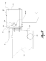
- figure 3 shows a schematic view of a boat with outboard motor fitted with a fuel supply system according to a further embodiment of the present invention
- figure 4 shows a perspective view of the detail IV in figure 3 .
- reference numeral 4 globally denotes a fuel supply system for motors 8 of motor boats 12, both of the outboard and inboard type, said motors being fuelled by alternative fuels.
- the present invention refers to any type of boat whether with an inboard or outboard motor.
- the motor 8 may comprise either a 4 stroke or 2 stroke endothermic motor, provided, preferably, with injection fuel supply (but also carburettor) devices.
- the motor 8 may be both bi-fuel and dual-fuel, an Otto cycle motor, or controlled ignition motor, Diesel cycle motor or compression ignition motor.
- the motor 8 may be aspirated or pressure charged, either 2 stroke or 4 stroke.
- the motor 8 may be operatively connected to means of propulsion of the boat 12, such as propellers 16, and/or to electricity generator means of the boat 12. In other words, the motor 8 may act as a means of propulsion and/or as a generator means of electricity.
- Alternative fuels are understood to be fuels in an essentially gaseous state, typically LPG, methane, hydrogen used in place of more traditional fuels such as petrol and gas-oil.
- the system 4 comprises a tank 20 of fuel, conserved in a liquid and/or gaseous state; the tank 20 is provided with a filler duct 21 and a distribution duct 22; filling may for example be through a special hose 23 connected to the filler duct 21.
- the tank is preferably provided with a fire resistant or in any case flame retardant protection.
- the system 4 comprises at least one pressure regulator 24 suitable for regulating the pressure of the fuel to be supplied to the motor 8.
- the pressure regulator 24 receives the fuel from a supply duct 28 at a fuel supply pressure and delivers it in output, through a delivery duct 32 at a delivery pressure, different from the supply pressure, to injection and/or solenoid valve or mixer devices which supply the motor 8 with fuel.
- the supply pressure is greater than the delivery pressure; moreover said supply and delivery pressures are greater than the environmental pressure or atmospheric pressure.
- the pressure regulator 24 can be connected to a heating circuit 36 suitable for heating the fuel coming out of the regulator 24 before it is supplied to the motor 8.
- a heating circuit 36 suitable for heating the fuel coming out of the regulator 24 before it is supplied to the motor 8.
- Such heating system may comprise one or more hot water pipes 37 which at least partially lap a regulator expansion chamber in which the fuel passes from the supply pressure to the delivery pressure, cooling on account of the reduction in pressure and relative expansion.
- Such cooling circuit may for example be at least partially a derivation of the cooling circuit of the motor 8.
- the system 4 comprises at least one closed container 40 which identifies an inner volume 44 containing said pressure regulator 24 and, at least partially, the supply and delivery ducts 28,32.
- the at least one container 40 is altogether hermetically tight sealed to the gaseous fuel, in relation to the fuel passing through the devices contained in it, such fuel being normally at a higher pressure than the environmental pressure where the system 4 is located.
- the container 40 is provided with a fire resistant or in any case flame retardant protection.
- the container 40 comprises at least one vent 48 in fluidic communication with the inner volume 44 of the container 40, the vent 48 fluidically connecting the inner volume 44 with the environment outside the system 4 and with the relative boat 12 which the system 4 is fitted in, so as to channel any fuel leaks, at a higher pressure than environmental pressure, towards the outside of the boat.
- hermetically tight sealed container should be considered in the sense that the container does not permit any leak of gas from the inner volume 44 outwards, except exclusively through the vents 48.
- the vents 48 are pipes which allow air to escape outside the boat.
- the vents 48 are provided with a fire resistant or in any case flame retardant protection; for example the vents 48 may be pipes covered with a fire resistant or flame retardant sheath.
- a gas detector device 52 may be positioned suitable for detecting the passage of gaseous fuel through such vent 48 and for signalling the presence of a leak.
- the gas detector 52 represents a further safety element. In fact any leaks of gas can only escape from the inner volume 44 through said vents 48. The positioning of the gas detector 52 at the vents 48 ensures that any leaks will be detected and signalled so as to further reduce the risks of explosion.
- At said vents 48 at said vents 48 at least one fan is positioned suitable to improve the extraction of any leaks of gas from the inner volume 44 towards the outside environment and/or suitable to improve the circulation of air inside the inner volume 44.
- the container 40 is attached to a portion of hull 56 of the boat 12 so as to be inside the boat 12 and said vent 48 opens onto the outside of the boat 12 so as to place the inner volume 44 in communication with the outside environment.
- said container 40 also encloses the motor 8; in other words, the housing compartment of the motor inside the boat 12, below deck, is hermetically sealed towards the outside except for the presence of the vents 48.
- the container 40 may contain and enclose the motor 8 but not necessarily.
- the motor 8 may be positioned inside or outside the container 40.
- vents 48 suitable for placing the inner volume 44 in communication with the outside environment, also supply an air suction system of the motor so as to enable the introduction of air from the outside environment in the motor, mixed with any gas leaks inside the container.
- vents act as means to channel towards the outside of the volume 44 any fuel leaks and to enable the suction of air by the motor 8, during its functioning.
- the suction of air means that any fuel leaks can be also be aspirated: in such case the leaks are recuperated and introduced into the motor to be combusted.
- the container 40 is attached directly onto the motor 8 and the motor 8 is outboard, that is external in relation to the hull 56 of the boat 12.
- the container 40 constitutes a casing enclosing the motor 8 which encloses the pressure regulator 24 and which is fitted with at least one vent 48 towards the outside environment.
- vent 48 in figure 4 is indicated merely for illustrative purposes but may be positioned in any other position of the casing or, preferably, may coincide with the air suction apertures of the motor itself.
- Said vent 48 is preferably positioned near an air suction system of the motor 8, so as to enable the supply of air to the motor 8 and to enable the introduction, directly into the motor 8 of any leaks of gas inside the container 40.
- the vents 48 act as means to channel towards the outside of the volume 44 any fuel leaks and to enable the suction of air by the motor 8, during its functioning; when the motor 8 is on, the suction of air makes it possible to aspirate any fuel leaks which are recuperated and introduced into the motor to be combusted.
- vents 48 need not necessarily be fitted and/or positioned on the casing of the motor ; in addition, the air inlets or apertures towards the motor, as well as enabling the correct aspiration of the motor may also act as vents for any fuel leaks.
- the pressure regulator 24 comprises attachment means 60 for the direct connection of the pressure regulator 24 to a portion of the associable alternatively fuelled motor 8, so as to result directly attached to a portion of said motor 8.
- the attachment means 60 comprise screws and/or bolts, preferably fitted with damper bushing and the like.
- the system according to the invention makes it possible to overcome the drawbacks mentioned with reference to the prior art.
- the system according to the present invention is extremely safe and exempt of the risk of explosion due to gas leaks.
- any gas leaks are expelled directly from the boat through the vents or, if envisaged, reintroduced into the suction system of the motor to be combusted; in the latter case, among other things, limiting consumption and the emission of pollutants.
- the presence of the gas detectors positioned near the vents or inside the container, makes it possible to immediately identify leaks and therefore warn the user to implement the system repairs required. In any case, thanks to the vents, the leaks are rendered safe by not stagnating inside the boat.
- both the regulator and the solenoid valves and/or injectors are subjected to the same source of vibrations; this way the breakages caused by vibrations for example of the supply ducts of the pressurised fuel to the reducer and of the expanded fuel to the solenoid valves of the motor, are limited.
- the position of the pressure reducer inside the hermetic container constitutes a further safety element in relation to possible leaks of water.
- the pressure reducer is normally heated by the water or liquid of the motor cooling circuit which is sent to the reducer by means of a heating circuit provided with relative pipes as described above. This way any leaks of water could dangerously flood the boat determining, at worst, its sinking.
- the containment of the pressure reducer, and therefore of the relative water supply pipes inside the hermetic container rather means that any leaks of water remain contained inside the container and at most, are expelled through the vents.
Abstract
Description
- The present invention relates to a fuel supply system for boats fuelled by alternative fuels such as LPG (liquefied petroleum gas), methane, hydrogen and the like.
- The invention also relates to a boat, of the type with outboard or inboard motor, comprising said fuel supply system.
- In particular, in alternatively fuelled motors, the fuel is usually compressed, in a liquid or gaseous phase, in pressurised tanks.
- Obviously, in order to be sent or supplied to the motor, the fuel must pass through pressure regulators, that is to say pressure vaporisers/reducers, in an accurate, controlled manner.
- The fuel is then sent from the pressure regulators to injectors or solenoid valves or mixers which inject the fuel into the intake manifold or directly into the engine cylinders, both in the gaseous or liquid phase. Such functioning may take place in both bi-fuel and dual-fuel motors, Otto cycle motors, or controlled ignition motors, Diesel cycle motors or compression ignition motors; in addition, the motor may be aspirated or pressure charged, 2 stroke or 4 stroke.
- The use of fuels such as LPG, methane, hydrogen or other fuels on boats while on the one hand greatly limiting the emission of pollutants, on the other entails some safety risks.
- In fact, the components of the fuel supply systems of motors contain pressurised gas which may be subject to leaks.
- Above all the marine environment accentuates corrosion phenomena of the system components (such as for example the gas supply pipes themselves) and therefore heightens the risk of the dispersion of gas in the boat environment.
- In addition, the pressure regulator is provided with fuel supply and delivery ducts which are subject not only to the corrosive action of the marine environment but also to the significant vibrations transmitted by the boat and by the motor.
- Such vibrations and corrosion contribute to damaging not only the regulator itself but also all the ducts connected to it and may cause gas leaks.
- The boat systems have some safety devices such as for example blow-off valves which are designed to prevent explosions of the pressure regulator, piping or tank.
- Despite this, any gas leaks are not always obstructed and/or detected and consequently, in specific functioning conditions, may cause dangerous explosions.
- The purpose of these present invention is to provide a fuel supply system for motor boats, whether with outboard or inboard motor, fuelled by alternative fuels, which overcomes the drawbacks mentioned with reference to the prior art, in terms of safety.
- Such drawbacks and limitations are resolved by a fuel supply system according to claim 1.
- Other embodiments of the fuel supply system according to the invention are described in the subsequent claims.
- Further characteristics and advantages of the present invention will be more clearly comprehensible from the description given below of its preferred and non-limiting embodiments, wherein:
-
figure 1 shows a schematic view of a boat with an inboard motor fitted with a fuel supply system according to one embodiment of the present invention; -
figure 1 shows a schematic view of the boat infigure 1 , according to an embodiment variation of the present invention; -
figure 3 shows a schematic view of a boat with outboard motor fitted with a fuel supply system according to a further embodiment of the present invention; -
figure 4 shows a perspective view of the detail IV infigure 3 . - The elements or parts of elements common to the embodiments described below will be indicated using the same reference numerals.
- With reference to the aforesaid figures,
reference numeral 4 globally denotes a fuel supply system formotors 8 ofmotor boats 12, both of the outboard and inboard type, said motors being fuelled by alternative fuels. - The present invention, as explained further below, refers to any type of boat whether with an inboard or outboard motor.
- The
motor 8 may comprise either a 4 stroke or 2 stroke endothermic motor, provided, preferably, with injection fuel supply (but also carburettor) devices. - In addition, the
motor 8 may be both bi-fuel and dual-fuel, an Otto cycle motor, or controlled ignition motor, Diesel cycle motor or compression ignition motor. In addition, themotor 8 may be aspirated or pressure charged, either 2 stroke or 4 stroke. - The
motor 8 may be operatively connected to means of propulsion of theboat 12, such aspropellers 16, and/or to electricity generator means of theboat 12. In other words, themotor 8 may act as a means of propulsion and/or as a generator means of electricity. - Alternative fuels are understood to be fuels in an essentially gaseous state, typically LPG, methane, hydrogen used in place of more traditional fuels such as petrol and gas-oil.
- The
system 4 comprises atank 20 of fuel, conserved in a liquid and/or gaseous state; thetank 20 is provided with afiller duct 21 and adistribution duct 22; filling may for example be through aspecial hose 23 connected to thefiller duct 21. - The tank is preferably provided with a fire resistant or in any case flame retardant protection.
- The
system 4 comprises at least onepressure regulator 24 suitable for regulating the pressure of the fuel to be supplied to themotor 8. - In particular, the
pressure regulator 24 receives the fuel from asupply duct 28 at a fuel supply pressure and delivers it in output, through adelivery duct 32 at a delivery pressure, different from the supply pressure, to injection and/or solenoid valve or mixer devices which supply themotor 8 with fuel. - Typically, the supply pressure is greater than the delivery pressure; moreover said supply and delivery pressures are greater than the environmental pressure or atmospheric pressure.
- the
pressure regulator 24 can be connected to a heating circuit 36 suitable for heating the fuel coming out of theregulator 24 before it is supplied to themotor 8. Such heating system may comprise one or more hot water pipes 37 which at least partially lap a regulator expansion chamber in which the fuel passes from the supply pressure to the delivery pressure, cooling on account of the reduction in pressure and relative expansion. Such cooling circuit may for example be at least partially a derivation of the cooling circuit of themotor 8. - Advantageously, the
system 4 comprises at least one closedcontainer 40 which identifies aninner volume 44 containing saidpressure regulator 24 and, at least partially, the supply anddelivery ducts - The at least one
container 40 is altogether hermetically tight sealed to the gaseous fuel, in relation to the fuel passing through the devices contained in it, such fuel being normally at a higher pressure than the environmental pressure where thesystem 4 is located. - Preferably, the
container 40 is provided with a fire resistant or in any case flame retardant protection. - Advantageously, the
container 40 comprises at least onevent 48 in fluidic communication with theinner volume 44 of thecontainer 40, thevent 48 fluidically connecting theinner volume 44 with the environment outside thesystem 4 and with therelative boat 12 which thesystem 4 is fitted in, so as to channel any fuel leaks, at a higher pressure than environmental pressure, towards the outside of the boat. - The definition of hermetically tight sealed container should be considered in the sense that the container does not permit any leak of gas from the
inner volume 44 outwards, except exclusively through thevents 48. - According to one embodiment, the
vents 48 are pipes which allow air to escape outside the boat. - Preferably, the
vents 48 are provided with a fire resistant or in any case flame retardant protection; for example thevents 48 may be pipes covered with a fire resistant or flame retardant sheath. - Any fuel leaks are normally at a higher pressure than the environmental pressure, so that in the inner volume an overpressure would arise in the case of any leaks which would automatically channel the fuel towards the
vents 48. - According to one embodiment, on at least one of said
vents 48, agas detector device 52 may be positioned suitable for detecting the passage of gaseous fuel throughsuch vent 48 and for signalling the presence of a leak. - The
gas detector 52 represents a further safety element. In fact any leaks of gas can only escape from theinner volume 44 through saidvents 48. The positioning of thegas detector 52 at thevents 48 ensures that any leaks will be detected and signalled so as to further reduce the risks of explosion. - According to a further embodiment, at said
vents 48 at least one fan is positioned suitable to improve the extraction of any leaks of gas from theinner volume 44 towards the outside environment and/or suitable to improve the circulation of air inside theinner volume 44. - According to one possible embodiment, typical of boats with inboard motors, the
container 40 is attached to a portion ofhull 56 of theboat 12 so as to be inside theboat 12 and saidvent 48 opens onto the outside of theboat 12 so as to place theinner volume 44 in communication with the outside environment. - According to a further possible embodiment (
figure 2 )" again in the case of boats with inboard motors, saidcontainer 40 also encloses themotor 8; in other words, the housing compartment of the motor inside theboat 12, below deck, is hermetically sealed towards the outside except for the presence of thevents 48. - In applications to boats with inboard motors, the
container 40 may contain and enclose themotor 8 but not necessarily. In other words, themotor 8 may be positioned inside or outside thecontainer 40. - In particular, the
vents 48, suitable for placing theinner volume 44 in communication with the outside environment, also supply an air suction system of the motor so as to enable the introduction of air from the outside environment in the motor, mixed with any gas leaks inside the container. - In other words, the vents act as means to channel towards the outside of the
volume 44 any fuel leaks and to enable the suction of air by themotor 8, during its functioning. - When the motor is on, the suction of air means that any fuel leaks can be also be aspirated: in such case the leaks are recuperated and introduced into the motor to be combusted.
- According to a further embodiment of the present invention, applied in particular to boats with outboard motors (
figure 3-4 ), thecontainer 40 is attached directly onto themotor 8 and themotor 8 is outboard, that is external in relation to thehull 56 of theboat 12. - According to such embodiment, the
container 40 constitutes a casing enclosing themotor 8 which encloses thepressure regulator 24 and which is fitted with at least onevent 48 towards the outside environment. - The
vent 48 infigure 4 is indicated merely for illustrative purposes but may be positioned in any other position of the casing or, preferably, may coincide with the air suction apertures of the motor itself. - Said
vent 48 is preferably positioned near an air suction system of themotor 8, so as to enable the supply of air to themotor 8 and to enable the introduction, directly into themotor 8 of any leaks of gas inside thecontainer 40. In other words, as seen for the systems with inboard motor, thevents 48 act as means to channel towards the outside of thevolume 44 any fuel leaks and to enable the suction of air by themotor 8, during its functioning; when themotor 8 is on, the suction of air makes it possible to aspirate any fuel leaks which are recuperated and introduced into the motor to be combusted. - In yet other words, in the case of an outboard motor, the
vents 48 need not necessarily be fitted and/or positioned on the casing of the motor ; in addition, the air inlets or apertures towards the motor, as well as enabling the correct aspiration of the motor may also act as vents for any fuel leaks. - With particular reference to outboard systems, the
pressure regulator 24 comprises attachment means 60 for the direct connection of thepressure regulator 24 to a portion of the associable alternatively fuelledmotor 8, so as to result directly attached to a portion of saidmotor 8. - This way the
pressure regulator 24, together with the injection devices and with therelative supply 28 anddelivery 32 ducts, receives the vibrations directly from themotor 8. The risk of cracking of said ducts, and possible fuel leaks, is thereby limited. - For example, the attachment means 60 comprise screws and/or bolts, preferably fitted with damper bushing and the like.
- As may be seen from the description, the system according to the invention makes it possible to overcome the drawbacks mentioned with reference to the prior art.
- In particular, the system according to the present invention is extremely safe and exempt of the risk of explosion due to gas leaks.
- In fact any gas leaks are expelled directly from the boat through the vents or, if envisaged, reintroduced into the suction system of the motor to be combusted; in the latter case, among other things, limiting consumption and the emission of pollutants.
- In addition, the presence of the gas detectors, positioned near the vents or inside the container, makes it possible to immediately identify leaks and therefore warn the user to implement the system repairs required. In any case, thanks to the vents, the leaks are rendered safe by not stagnating inside the boat.
- Lastly, the attachment of the pressure regulator directly to the motor resolves further technical problems related to possible fuel leaks.
- In fact, both the regulator and the solenoid valves and/or injectors are subjected to the same source of vibrations; this way the breakages caused by vibrations for example of the supply ducts of the pressurised fuel to the reducer and of the expanded fuel to the solenoid valves of the motor, are limited.
- In addition, the position of the pressure reducer inside the hermetic container constitutes a further safety element in relation to possible leaks of water. In fact, the pressure reducer is normally heated by the water or liquid of the motor cooling circuit which is sent to the reducer by means of a heating circuit provided with relative pipes as described above. This way any leaks of water could dangerously flood the boat determining, at worst, its sinking. The containment of the pressure reducer, and therefore of the relative water supply pipes inside the hermetic container rather means that any leaks of water remain contained inside the container and at most, are expelled through the vents.
- A person skilled in the art may make numerous modifications and variations to the fuel supply systems described above so as to satisfy contingent and specific requirements, while remaining within the sphere of protection of the invention as defined by the following claims
Claims (10)
- Fuel supply system (4) for motors (8) of motor boats (12) both of the outboard and inboard type, said motors (8)being fuelled by alternative fuels, the system (4) comprising- at least one pressure regulator (24), said pressure regulator (24) receiving the fuel from a supply duct (28)at a supply pressure and delivering it in output, through a delivery duct (32) at a delivery pressure, different from the supply pressure, to injection and/or solenoid valve devices which supply the motor (8) with fuel,- said supply and delivery pressures being greater than the environmental pressure,
characterised by the fact that- the system (4) comprises at least one closed container (40) which identifies an inner volume (44) containing said pressure regulator (24) and, at least partially, said supply (28) and delivery (32) ducts,- the closed container (40) altogether hermetically tight sealed to the gaseous fuel, in relation to the fuel passing through the devices contained in it, said fuel being supplied at a higher pressure than the environmental pressure where the system (4) is located,- said closed container (40) comprising at least one vent (48) in fluidic communication with the inner volume (44) of the container (40), the vent (48) fluidically connecting said inner volume (44) with the environment outside the system (4) and with the relative boat (12) which the system (4) is fitted in, so as to channel any fuel leaks, at a higher pressure than environmental pressure, towards the outside of the boat (12). - System (4) according to claim 1, wherein, on at least one of said vents (48), a gas detector device (52) is positioned able to detect the passage of gaseous fuel through said vent (48) and to signal the presence of a leak of fuel.
- System (4) according to claim 1 or 2, wherein, at said vents (48) at least one fan is positioned suitable to improve the extraction of any leaks of gas from the inner volume (44) towards the outside environment and/or suitable to improve the circulation of air inside the inner volume (44).
- System (4) according to claim 1, 2 or 3 wherein said closed container (40) is attached to a portion of hull (56) of the boat (12) so as to be inside the boat (12) and said vent (48) opens onto the outside of the boat (12) so as to place the inner volume (44) in communication with the outside environment.
- System (4) according to any of the previous claims, wherein said closed container (40) also encloses the motor (8) and wherein said vents (48), suitable for placing the inner volume (44) in fluidic communication with the outside environment, fuel an air suction system of the motor (8) so as to enable the introduction of air from the outside environment in the motor (8), mixed with any gas leaks inside the container (40).
- System (4) according to any of the claims from 1 to 3, wherein the closed container (40) is attached directly onto the motor (8) and the motor (8) is outboard, that is in relation to a hull (56) of the boat (12).
- System (4) according to claim 6, wherein the closed container (40) constitutes a casing enclosing the motor (8) which encloses the pressure regulator (24) and is fitted with at least one vent (48) towards the outside environment.
- System (4) according to claim 6 or 7, wherein said vent (48) is positioned near an air suction system of the motor (8), so as to enable the supply of air to the motor (8) and to enable the introduction, directly into the motor (8) of any leaks of gas inside the closed container (40).
- System (4) according to any of the claims from 6 to 8, wherein the pressure regulator (24) comprises attachment means (60) for the direct connection of the regulator (24) to a portion of the associable alternatively fuelled motor (8), so as to result directly attached to a portion of said motor (8).
- Boat (12) with inboard or outboard motor comprising a fuel supply system (4) according to any of the previous claims.
Priority Applications (3)
| Application Number | Priority Date | Filing Date | Title |
|---|---|---|---|
| SI201230271T SI2503128T1 (en) | 2011-03-21 | 2012-03-21 | Fuel supply system for boats fuelled by alternative fuels and relative boats |
| PL12160539T PL2503128T3 (en) | 2011-03-21 | 2012-03-21 | Fuel supply system for boats fuelled by alternative fuels and relative boats |
| HRP20150812TT HRP20150812T1 (en) | 2011-03-21 | 2015-07-27 | Fuel supply system for boats fuelled by alternative fuels and relative boats |
Applications Claiming Priority (1)
| Application Number | Priority Date | Filing Date | Title |
|---|---|---|---|
| IT000086A ITPD20110086A1 (en) | 2011-03-21 | 2011-03-21 | POWER SUPPLY FOR BOATS POWERED AT ALTERNATIVE FUELS AND RELATIVE BOATS |
Publications (2)
| Publication Number | Publication Date |
|---|---|
| EP2503128A1 true EP2503128A1 (en) | 2012-09-26 |
| EP2503128B1 EP2503128B1 (en) | 2015-04-29 |
Family
ID=43977264
Family Applications (1)
| Application Number | Title | Priority Date | Filing Date |
|---|---|---|---|
| EP20120160539 Not-in-force EP2503128B1 (en) | 2011-03-21 | 2012-03-21 | Fuel supply system for boats fuelled by alternative fuels and relative boats |
Country Status (8)
| Country | Link |
|---|---|
| EP (1) | EP2503128B1 (en) |
| DK (1) | DK2503128T3 (en) |
| ES (1) | ES2543886T3 (en) |
| HR (1) | HRP20150812T1 (en) |
| IT (1) | ITPD20110086A1 (en) |
| PL (1) | PL2503128T3 (en) |
| PT (1) | PT2503128E (en) |
| SI (1) | SI2503128T1 (en) |
Cited By (1)
| Publication number | Priority date | Publication date | Assignee | Title |
|---|---|---|---|---|
| ITLE20130009A1 (en) * | 2013-06-19 | 2014-12-20 | Marco Casamassima | TRANSFORMATION KIT FOR LPG OUTBOARD MOTORS |
Citations (8)
| Publication number | Priority date | Publication date | Assignee | Title |
|---|---|---|---|---|
| US3115114A (en) * | 1962-02-07 | 1963-12-24 | Outboard Marine Corp | Fuel delivery system including an anti-siphoning feature |
| GB2044349A (en) * | 1979-03-20 | 1980-10-15 | Orford J R | Apparatus for Feeding Fuel to a Marine Engine |
| WO1984001339A1 (en) * | 1982-10-04 | 1984-04-12 | Moss Rosenberg Verft As | A device, a procedure and employment concerning diesel engines using two different fuels and employment of the device for starting such engines |
| DE9202573U1 (en) * | 1992-02-27 | 1992-04-16 | Karg, Erich, 8071 Muenchsmuenster, De | |
| US5197910A (en) * | 1990-07-02 | 1993-03-30 | Yamaha Hatsudoki Kabushiki Kaisha | Outboard motor |
| DE19802643A1 (en) * | 1997-01-29 | 1998-07-30 | Man B & W Diesel Gmbh | Diesel engine running on gaseous fuel |
| US7021249B1 (en) * | 2003-09-02 | 2006-04-04 | Christison J Devon | Hydrogen addition to hydrocarbon fuel for an internal combustion engine |
| CN2792945Y (en) * | 2005-04-19 | 2006-07-05 | 王金生 | Ship with gas IC engine as power |
-
2011
- 2011-03-21 IT IT000086A patent/ITPD20110086A1/en unknown
-
2012
- 2012-03-21 EP EP20120160539 patent/EP2503128B1/en not_active Not-in-force
- 2012-03-21 DK DK12160539.8T patent/DK2503128T3/en active
- 2012-03-21 PT PT121605398T patent/PT2503128E/en unknown
- 2012-03-21 PL PL12160539T patent/PL2503128T3/en unknown
- 2012-03-21 SI SI201230271T patent/SI2503128T1/en unknown
- 2012-03-21 ES ES12160539.8T patent/ES2543886T3/en active Active
-
2015
- 2015-07-27 HR HRP20150812TT patent/HRP20150812T1/en unknown
Patent Citations (8)
| Publication number | Priority date | Publication date | Assignee | Title |
|---|---|---|---|---|
| US3115114A (en) * | 1962-02-07 | 1963-12-24 | Outboard Marine Corp | Fuel delivery system including an anti-siphoning feature |
| GB2044349A (en) * | 1979-03-20 | 1980-10-15 | Orford J R | Apparatus for Feeding Fuel to a Marine Engine |
| WO1984001339A1 (en) * | 1982-10-04 | 1984-04-12 | Moss Rosenberg Verft As | A device, a procedure and employment concerning diesel engines using two different fuels and employment of the device for starting such engines |
| US5197910A (en) * | 1990-07-02 | 1993-03-30 | Yamaha Hatsudoki Kabushiki Kaisha | Outboard motor |
| DE9202573U1 (en) * | 1992-02-27 | 1992-04-16 | Karg, Erich, 8071 Muenchsmuenster, De | |
| DE19802643A1 (en) * | 1997-01-29 | 1998-07-30 | Man B & W Diesel Gmbh | Diesel engine running on gaseous fuel |
| US7021249B1 (en) * | 2003-09-02 | 2006-04-04 | Christison J Devon | Hydrogen addition to hydrocarbon fuel for an internal combustion engine |
| CN2792945Y (en) * | 2005-04-19 | 2006-07-05 | 王金生 | Ship with gas IC engine as power |
Cited By (3)
| Publication number | Priority date | Publication date | Assignee | Title |
|---|---|---|---|---|
| ITLE20130009A1 (en) * | 2013-06-19 | 2014-12-20 | Marco Casamassima | TRANSFORMATION KIT FOR LPG OUTBOARD MOTORS |
| WO2014203145A1 (en) * | 2013-06-19 | 2014-12-24 | Casamassima Marco | Kit for the realization of a dual lpg/petrol fuel system for outboard engines for motorboats |
| US10066554B2 (en) | 2013-06-19 | 2018-09-04 | Marco Casamassima | Kit for the realization of a dual LPG/petrol fuel system for outboard engines for motorboats |
Also Published As
| Publication number | Publication date |
|---|---|
| ES2543886T3 (en) | 2015-08-25 |
| PT2503128E (en) | 2015-08-28 |
| EP2503128B1 (en) | 2015-04-29 |
| SI2503128T1 (en) | 2015-12-31 |
| HRP20150812T1 (en) | 2015-11-06 |
| ITPD20110086A1 (en) | 2012-09-22 |
| PL2503128T3 (en) | 2016-01-29 |
| DK2503128T3 (en) | 2015-08-03 |
Similar Documents
| Publication | Publication Date | Title |
|---|---|---|
| US20030221433A1 (en) | Natural gas fuel storage and supply system for vehicles | |
| US3789820A (en) | Compressed gaseous fuel system | |
| KR102355332B1 (en) | Liquefied gas fuel supply systems and ships | |
| JP6154980B1 (en) | Gas piping system and ship equipped with the same | |
| CN213065523U (en) | Marine liquefied natural gas low pressure fuel supply system | |
| CN203428013U (en) | LNG (liquefied natural gas) fuel storage tank structure and LNG ship | |
| US7793620B2 (en) | Integrated gaseous fuel delivery system | |
| EP2503128B1 (en) | Fuel supply system for boats fuelled by alternative fuels and relative boats | |
| KR100986276B1 (en) | Pipe for high-pressure fuel in LNG ship | |
| KR102177571B1 (en) | Vessel | |
| CN113175379B (en) | Internal combustion engine system | |
| CN206107532U (en) | Natural gas transmission system of LNG power driving vessel | |
| KR101512694B1 (en) | Liquefied fuel gas venting system and offshore structure having the same | |
| RU2557872C1 (en) | System for on-board safe filling with liquefied natural gas | |
| DK202101100A1 (en) | Fuel supply system for large two-stroke turbo-charged uniflow-scavenged crosshead internal combustion engine | |
| EP1882879A2 (en) | Refueling system for CNG fueled vehicles | |
| Lee et al. | Quantitative risk analysis for gas leak and dispersion in cargo compressor room of 174K ME-GI LNG vessels | |
| KR20200074140A (en) | Mobile container-tank module | |
| US20220154884A1 (en) | Lpg fuel supply system with vapor lock prevention | |
| Noh et al. | Conceptual Design of the Fuel Injection Valve Tester for ME-LGI Marine Engine by Using System Engineering | |
| US20110100335A1 (en) | Fuel delivery system | |
| DK201300607A1 (en) | A large ocean going cargo ship or freighter with a crude oil fuel system | |
| DK178103B1 (en) | A large ocean going cargo ship or freighter with a crude oil fuel system | |
| CN115112314A (en) | Single-cylinder pump pressure checking method for LGIP (liquefied Natural gas) host of marine diesel engine | |
| EP2479416A1 (en) | Pressure regulator for fuel systems for motors of alternatively fuelled boats |
Legal Events
| Date | Code | Title | Description |
|---|---|---|---|
| PUAI | Public reference made under article 153(3) epc to a published international application that has entered the european phase |
Free format text: ORIGINAL CODE: 0009012 |
|
| 17P | Request for examination filed |
Effective date: 20120731 |
|
| AK | Designated contracting states |
Kind code of ref document: A1 Designated state(s): AL AT BE BG CH CY CZ DE DK EE ES FI FR GB GR HR HU IE IS IT LI LT LU LV MC MK MT NL NO PL PT RO RS SE SI SK SM TR |
|
| AX | Request for extension of the european patent |
Extension state: BA ME |
|
| 17Q | First examination report despatched |
Effective date: 20130828 |
|
| GRAP | Despatch of communication of intention to grant a patent |
Free format text: ORIGINAL CODE: EPIDOSNIGR1 |
|
| INTG | Intention to grant announced |
Effective date: 20141203 |
|
| GRAS | Grant fee paid |
Free format text: ORIGINAL CODE: EPIDOSNIGR3 |
|
| GRAA | (expected) grant |
Free format text: ORIGINAL CODE: 0009210 |
|
| AK | Designated contracting states |
Kind code of ref document: B1 Designated state(s): AL AT BE BG CH CY CZ DE DK EE ES FI FR GB GR HR HU IE IS IT LI LT LU LV MC MK MT NL NO PL PT RO RS SE SI SK SM TR |
|
| REG | Reference to a national code |
Ref country code: GB Ref legal event code: FG4D |
|
| REG | Reference to a national code |
Ref country code: CH Ref legal event code: EP |
|
| REG | Reference to a national code |
Ref country code: AT Ref legal event code: REF Ref document number: 724574 Country of ref document: AT Kind code of ref document: T Effective date: 20150515 |
|
| REG | Reference to a national code |
Ref country code: IE Ref legal event code: FG4D |
|
| REG | Reference to a national code |
Ref country code: DE Ref legal event code: R096 Ref document number: 602012006956 Country of ref document: DE Effective date: 20150611 |
|
| REG | Reference to a national code |
Ref country code: HR Ref legal event code: TUEP Ref document number: P20150812 Country of ref document: HR |
|
| REG | Reference to a national code |
Ref country code: RO Ref legal event code: EPE |
|
| REG | Reference to a national code |
Ref country code: DK Ref legal event code: T3 Effective date: 20150730 |
|
| REG | Reference to a national code |
Ref country code: SE Ref legal event code: TRGR |
|
| REG | Reference to a national code |
Ref country code: NL Ref legal event code: SD Effective date: 20150806 Ref country code: NL Ref legal event code: T3 |
|
| RAP2 | Party data changed (patent owner data changed or rights of a patent transferred) |
Owner name: SICURGAS S.R.L. |
|
| REG | Reference to a national code |
Ref country code: ES Ref legal event code: FG2A Ref document number: 2543886 Country of ref document: ES Kind code of ref document: T3 Effective date: 20150825 |
|
| REG | Reference to a national code |
Ref country code: GB Ref legal event code: 732E Free format text: REGISTERED BETWEEN 20150730 AND 20150805 |
|
| REG | Reference to a national code |
Ref country code: PT Ref legal event code: SC4A Free format text: AVAILABILITY OF NATIONAL TRANSLATION Effective date: 20150728 |
|
| REG | Reference to a national code |
Ref country code: PT Ref legal event code: PC4A Owner name: SICURGAS S.R.L., IT Effective date: 20150728 |
|
| REG | Reference to a national code |
Ref country code: AT Ref legal event code: MK05 Ref document number: 724574 Country of ref document: AT Kind code of ref document: T Effective date: 20150429 |
|
| REG | Reference to a national code |
Ref country code: NO Ref legal event code: T2 Effective date: 20150429 |
|
| REG | Reference to a national code |
Ref country code: GR Ref legal event code: EP Ref document number: 20150401584 Country of ref document: GR Effective date: 20150929 |
|
| REG | Reference to a national code |
Ref country code: HR Ref legal event code: T1PR Ref document number: P20150812 Country of ref document: HR |
|
| REG | Reference to a national code |
Ref country code: EE Ref legal event code: FG4A Ref document number: E011047 Country of ref document: EE Effective date: 20150728 |
|
| PG25 | Lapsed in a contracting state [announced via postgrant information from national office to epo] |
Ref country code: IS Free format text: LAPSE BECAUSE OF FAILURE TO SUBMIT A TRANSLATION OF THE DESCRIPTION OR TO PAY THE FEE WITHIN THE PRESCRIBED TIME-LIMIT Effective date: 20150829 Ref country code: RS Free format text: LAPSE BECAUSE OF FAILURE TO SUBMIT A TRANSLATION OF THE DESCRIPTION OR TO PAY THE FEE WITHIN THE PRESCRIBED TIME-LIMIT Effective date: 20150429 Ref country code: AT Free format text: LAPSE BECAUSE OF FAILURE TO SUBMIT A TRANSLATION OF THE DESCRIPTION OR TO PAY THE FEE WITHIN THE PRESCRIBED TIME-LIMIT Effective date: 20150429 |
|
| REG | Reference to a national code |
Ref country code: SK Ref legal event code: T3 Ref document number: E 19302 Country of ref document: SK |
|
| REG | Reference to a national code |
Ref country code: DE Ref legal event code: R097 Ref document number: 602012006956 Country of ref document: DE |
|
| PG25 | Lapsed in a contracting state [announced via postgrant information from national office to epo] |
Ref country code: CZ Free format text: LAPSE BECAUSE OF FAILURE TO SUBMIT A TRANSLATION OF THE DESCRIPTION OR TO PAY THE FEE WITHIN THE PRESCRIBED TIME-LIMIT Effective date: 20150429 |
|
| PLBE | No opposition filed within time limit |
Free format text: ORIGINAL CODE: 0009261 |
|
| STAA | Information on the status of an ep patent application or granted ep patent |
Free format text: STATUS: NO OPPOSITION FILED WITHIN TIME LIMIT |
|
| REG | Reference to a national code |
Ref country code: FR Ref legal event code: PLFP Year of fee payment: 5 |
|
| 26N | No opposition filed |
Effective date: 20160201 |
|
| PG25 | Lapsed in a contracting state [announced via postgrant information from national office to epo] |
Ref country code: MC Free format text: LAPSE BECAUSE OF FAILURE TO SUBMIT A TRANSLATION OF THE DESCRIPTION OR TO PAY THE FEE WITHIN THE PRESCRIBED TIME-LIMIT Effective date: 20150429 Ref country code: LU Free format text: LAPSE BECAUSE OF FAILURE TO SUBMIT A TRANSLATION OF THE DESCRIPTION OR TO PAY THE FEE WITHIN THE PRESCRIBED TIME-LIMIT Effective date: 20160321 |
|
| REG | Reference to a national code |
Ref country code: CH Ref legal event code: PL |
|
| PG25 | Lapsed in a contracting state [announced via postgrant information from national office to epo] |
Ref country code: LI Free format text: LAPSE BECAUSE OF NON-PAYMENT OF DUE FEES Effective date: 20160331 Ref country code: CH Free format text: LAPSE BECAUSE OF NON-PAYMENT OF DUE FEES Effective date: 20160331 |
|
| REG | Reference to a national code |
Ref country code: HR Ref legal event code: ODRP Ref document number: P20150812 Country of ref document: HR Payment date: 20170320 Year of fee payment: 6 |
|
| REG | Reference to a national code |
Ref country code: FR Ref legal event code: PLFP Year of fee payment: 6 |
|
| PGFP | Annual fee paid to national office [announced via postgrant information from national office to epo] |
Ref country code: DE Payment date: 20170322 Year of fee payment: 6 Ref country code: FI Payment date: 20170328 Year of fee payment: 6 Ref country code: SE Payment date: 20170321 Year of fee payment: 6 Ref country code: GR Payment date: 20170330 Year of fee payment: 6 Ref country code: EE Payment date: 20170328 Year of fee payment: 6 Ref country code: NL Payment date: 20170317 Year of fee payment: 6 Ref country code: RO Payment date: 20170320 Year of fee payment: 6 Ref country code: FR Payment date: 20170321 Year of fee payment: 6 Ref country code: NO Payment date: 20170323 Year of fee payment: 6 |
|
| PGFP | Annual fee paid to national office [announced via postgrant information from national office to epo] |
Ref country code: HR Payment date: 20170320 Year of fee payment: 6 Ref country code: GB Payment date: 20170322 Year of fee payment: 6 Ref country code: SK Payment date: 20170315 Year of fee payment: 6 Ref country code: BE Payment date: 20170310 Year of fee payment: 6 Ref country code: DK Payment date: 20170321 Year of fee payment: 6 Ref country code: PT Payment date: 20170321 Year of fee payment: 6 Ref country code: SI Payment date: 20170313 Year of fee payment: 6 Ref country code: PL Payment date: 20170331 Year of fee payment: 6 Ref country code: IE Payment date: 20170321 Year of fee payment: 6 Ref country code: LV Payment date: 20170329 Year of fee payment: 6 |
|
| PGFP | Annual fee paid to national office [announced via postgrant information from national office to epo] |
Ref country code: IT Payment date: 20170324 Year of fee payment: 6 Ref country code: TR Payment date: 20170320 Year of fee payment: 6 |
|
| PGFP | Annual fee paid to national office [announced via postgrant information from national office to epo] |
Ref country code: LT Payment date: 20170407 Year of fee payment: 6 Ref country code: AL Payment date: 20170328 Year of fee payment: 6 |
|
| PG25 | Lapsed in a contracting state [announced via postgrant information from national office to epo] |
Ref country code: MT Free format text: LAPSE BECAUSE OF FAILURE TO SUBMIT A TRANSLATION OF THE DESCRIPTION OR TO PAY THE FEE WITHIN THE PRESCRIBED TIME-LIMIT Effective date: 20150429 |
|
| PGFP | Annual fee paid to national office [announced via postgrant information from national office to epo] |
Ref country code: ES Payment date: 20170412 Year of fee payment: 6 |
|
| PG25 | Lapsed in a contracting state [announced via postgrant information from national office to epo] |
Ref country code: SM Free format text: LAPSE BECAUSE OF FAILURE TO SUBMIT A TRANSLATION OF THE DESCRIPTION OR TO PAY THE FEE WITHIN THE PRESCRIBED TIME-LIMIT Effective date: 20150429 Ref country code: HU Free format text: LAPSE BECAUSE OF FAILURE TO SUBMIT A TRANSLATION OF THE DESCRIPTION OR TO PAY THE FEE WITHIN THE PRESCRIBED TIME-LIMIT; INVALID AB INITIO Effective date: 20120321 Ref country code: CY Free format text: LAPSE BECAUSE OF FAILURE TO SUBMIT A TRANSLATION OF THE DESCRIPTION OR TO PAY THE FEE WITHIN THE PRESCRIBED TIME-LIMIT Effective date: 20150429 |
|
| PG25 | Lapsed in a contracting state [announced via postgrant information from national office to epo] |
Ref country code: MT Free format text: LAPSE BECAUSE OF FAILURE TO SUBMIT A TRANSLATION OF THE DESCRIPTION OR TO PAY THE FEE WITHIN THE PRESCRIBED TIME-LIMIT Effective date: 20160331 Ref country code: MK Free format text: LAPSE BECAUSE OF FAILURE TO SUBMIT A TRANSLATION OF THE DESCRIPTION OR TO PAY THE FEE WITHIN THE PRESCRIBED TIME-LIMIT Effective date: 20150429 |
|
| PG25 | Lapsed in a contracting state [announced via postgrant information from national office to epo] |
Ref country code: BG Free format text: LAPSE BECAUSE OF FAILURE TO SUBMIT A TRANSLATION OF THE DESCRIPTION OR TO PAY THE FEE WITHIN THE PRESCRIBED TIME-LIMIT Effective date: 20150429 |
|
| REG | Reference to a national code |
Ref country code: HR Ref legal event code: PBON Ref document number: P20150812 Country of ref document: HR Effective date: 20180321 |
|
| REG | Reference to a national code |
Ref country code: DE Ref legal event code: R119 Ref document number: 602012006956 Country of ref document: DE |
|
| REG | Reference to a national code |
Ref country code: LT Ref legal event code: MM4D Effective date: 20180321 |
|
| REG | Reference to a national code |
Ref country code: EE Ref legal event code: MM4A Ref document number: E011047 Country of ref document: EE Effective date: 20180331 |
|
| REG | Reference to a national code |
Ref country code: NO Ref legal event code: MMEP |
|
| REG | Reference to a national code |
Ref country code: DK Ref legal event code: EBP Effective date: 20180331 |
|
| PG25 | Lapsed in a contracting state [announced via postgrant information from national office to epo] |
Ref country code: LT Free format text: LAPSE BECAUSE OF NON-PAYMENT OF DUE FEES Effective date: 20180321 Ref country code: PT Free format text: LAPSE BECAUSE OF NON-PAYMENT OF DUE FEES Effective date: 20180921 Ref country code: SE Free format text: LAPSE BECAUSE OF NON-PAYMENT OF DUE FEES Effective date: 20180322 Ref country code: RO Free format text: LAPSE BECAUSE OF NON-PAYMENT OF DUE FEES Effective date: 20180321 Ref country code: FI Free format text: LAPSE BECAUSE OF NON-PAYMENT OF DUE FEES Effective date: 20180321 |
|
| REG | Reference to a national code |
Ref country code: NL Ref legal event code: MM Effective date: 20180401 |
|
| GBPC | Gb: european patent ceased through non-payment of renewal fee |
Effective date: 20180321 |
|
| PG25 | Lapsed in a contracting state [announced via postgrant information from national office to epo] |
Ref country code: LV Free format text: LAPSE BECAUSE OF NON-PAYMENT OF DUE FEES Effective date: 20180321 |
|
| REG | Reference to a national code |
Ref country code: SK Ref legal event code: MM4A Ref document number: E 19302 Country of ref document: SK Effective date: 20180321 |
|
| REG | Reference to a national code |
Ref country code: BE Ref legal event code: FP Effective date: 20150729 Ref country code: BE Ref legal event code: MM Effective date: 20180331 Ref country code: BE Ref legal event code: PD Owner name: SICURGAS S.R.L.; IT Free format text: DETAILS ASSIGNMENT: CHANGE OF OWNER(S), AFFECTATION / CESSION; FORMER OWNER NAME: CVO TECHNOLOGIES S.R.L. Effective date: 20160204 |
|
| REG | Reference to a national code |
Ref country code: IE Ref legal event code: MM4A |
|
| PG25 | Lapsed in a contracting state [announced via postgrant information from national office to epo] |
Ref country code: NL Free format text: LAPSE BECAUSE OF NON-PAYMENT OF DUE FEES Effective date: 20180401 |
|
| REG | Reference to a national code |
Ref country code: SI Ref legal event code: KO00 Effective date: 20181106 |
|
| PG25 | Lapsed in a contracting state [announced via postgrant information from national office to epo] |
Ref country code: DE Free format text: LAPSE BECAUSE OF NON-PAYMENT OF DUE FEES Effective date: 20181002 Ref country code: GR Free format text: LAPSE BECAUSE OF NON-PAYMENT OF DUE FEES Effective date: 20181003 Ref country code: IE Free format text: LAPSE BECAUSE OF NON-PAYMENT OF DUE FEES Effective date: 20180321 Ref country code: EE Free format text: LAPSE BECAUSE OF NON-PAYMENT OF DUE FEES Effective date: 20180331 Ref country code: NO Free format text: LAPSE BECAUSE OF NON-PAYMENT OF DUE FEES Effective date: 20180331 Ref country code: SK Free format text: LAPSE BECAUSE OF NON-PAYMENT OF DUE FEES Effective date: 20180321 |
|
| PG25 | Lapsed in a contracting state [announced via postgrant information from national office to epo] |
Ref country code: BE Free format text: LAPSE BECAUSE OF NON-PAYMENT OF DUE FEES Effective date: 20180331 Ref country code: IT Free format text: LAPSE BECAUSE OF NON-PAYMENT OF DUE FEES Effective date: 20180321 Ref country code: HR Free format text: LAPSE BECAUSE OF NON-PAYMENT OF DUE FEES Effective date: 20180321 Ref country code: SI Free format text: LAPSE BECAUSE OF NON-PAYMENT OF DUE FEES Effective date: 20180322 Ref country code: GB Free format text: LAPSE BECAUSE OF NON-PAYMENT OF DUE FEES Effective date: 20180321 |
|
| PG25 | Lapsed in a contracting state [announced via postgrant information from national office to epo] |
Ref country code: FR Free format text: LAPSE BECAUSE OF NON-PAYMENT OF DUE FEES Effective date: 20180331 |
|
| PG25 | Lapsed in a contracting state [announced via postgrant information from national office to epo] |
Ref country code: DK Free format text: LAPSE BECAUSE OF NON-PAYMENT OF DUE FEES Effective date: 20180331 |
|
| REG | Reference to a national code |
Ref country code: ES Ref legal event code: FD2A Effective date: 20190909 |
|
| PG25 | Lapsed in a contracting state [announced via postgrant information from national office to epo] |
Ref country code: ES Free format text: LAPSE BECAUSE OF NON-PAYMENT OF DUE FEES Effective date: 20180322 |
|
| PG25 | Lapsed in a contracting state [announced via postgrant information from national office to epo] |
Ref country code: PL Free format text: LAPSE BECAUSE OF NON-PAYMENT OF DUE FEES Effective date: 20180321 |
|
| PG25 | Lapsed in a contracting state [announced via postgrant information from national office to epo] |
Ref country code: AL Free format text: LAPSE BECAUSE OF NON-PAYMENT OF DUE FEES Effective date: 20180321 |
|
| PG25 | Lapsed in a contracting state [announced via postgrant information from national office to epo] |
Ref country code: TR Free format text: LAPSE BECAUSE OF NON-PAYMENT OF DUE FEES Effective date: 20180321 |