EP2482152A1 - Method for use in installing a home automation system, computer medium and computer program - Google Patents
Method for use in installing a home automation system, computer medium and computer program Download PDFInfo
- Publication number
- EP2482152A1 EP2482152A1 EP12152110A EP12152110A EP2482152A1 EP 2482152 A1 EP2482152 A1 EP 2482152A1 EP 12152110 A EP12152110 A EP 12152110A EP 12152110 A EP12152110 A EP 12152110A EP 2482152 A1 EP2482152 A1 EP 2482152A1
- Authority
- EP
- European Patent Office
- Prior art keywords
- operating means
- devices
- user
- module
- modules
- Prior art date
- Legal status (The legal status is an assumption and is not a legal conclusion. Google has not performed a legal analysis and makes no representation as to the accuracy of the status listed.)
- Granted
Links
Images


Classifications
-
- G—PHYSICS
- G05—CONTROLLING; REGULATING
- G05B—CONTROL OR REGULATING SYSTEMS IN GENERAL; FUNCTIONAL ELEMENTS OF SUCH SYSTEMS; MONITORING OR TESTING ARRANGEMENTS FOR SUCH SYSTEMS OR ELEMENTS
- G05B19/00—Programme-control systems
- G05B19/02—Programme-control systems electric
- G05B19/04—Programme control other than numerical control, i.e. in sequence controllers or logic controllers
- G05B19/042—Programme control other than numerical control, i.e. in sequence controllers or logic controllers using digital processors
-
- G—PHYSICS
- G05—CONTROLLING; REGULATING
- G05B—CONTROL OR REGULATING SYSTEMS IN GENERAL; FUNCTIONAL ELEMENTS OF SUCH SYSTEMS; MONITORING OR TESTING ARRANGEMENTS FOR SUCH SYSTEMS OR ELEMENTS
- G05B2219/00—Program-control systems
- G05B2219/10—Plc systems
- G05B2219/13—Plc programming
- G05B2219/13144—GUI graphical user interface, icon, function bloc editor, OI operator interface
-
- G—PHYSICS
- G05—CONTROLLING; REGULATING
- G05B—CONTROL OR REGULATING SYSTEMS IN GENERAL; FUNCTIONAL ELEMENTS OF SUCH SYSTEMS; MONITORING OR TESTING ARRANGEMENTS FOR SUCH SYSTEMS OR ELEMENTS
- G05B2219/00—Program-control systems
- G05B2219/20—Pc systems
- G05B2219/23—Pc programming
- G05B2219/23258—GUI graphical user interface, icon, function bloc editor, labview
-
- G—PHYSICS
- G05—CONTROLLING; REGULATING
- G05B—CONTROL OR REGULATING SYSTEMS IN GENERAL; FUNCTIONAL ELEMENTS OF SUCH SYSTEMS; MONITORING OR TESTING ARRANGEMENTS FOR SUCH SYSTEMS OR ELEMENTS
- G05B2219/00—Program-control systems
- G05B2219/20—Pc systems
- G05B2219/26—Pc applications
- G05B2219/2642—Domotique, domestic, home control, automation, smart house
Definitions
- the present invention relates to a method for preparing or completing an installation of an automation or home automation system in a building or the like.
- the invention further relates to a computer program for use in performing such a method and a computer medium for storing program instructions of such a computer program.
- An automation system is typically a system designed for operating a number of devices by means of modules on a module assembly site, typically in at least one control box or by using modules distributed within the automation system and by means of operating means such as a button or a sensor.
- These operating means are typically provided with an IP address and arranged to communicate via a communication system, such as a bus, but it could also be a wireless communication system.
- the devices are electrical loads which are typically not provided with intelligence. According to the methods of the prior art, one usually starts thinking starting from the control box. This means that initially the necessary components will be provided in the control box and from there the necessary connections with the equipment and operating means are realized. Also, in the computer programs used to program a home automation system, one may start from the virtual control box from where virtual links are realized with the equipment and operating means.
- the present invention aims to provide a method of the type mentioned in the introduction which is more user-friendly, and allows to install in a more organized way an automation or home automation system.
- the method according to the invention is characterized in that it includes:
- home automation system is to be understood to comprise both a domestic automation system as an automation system in an industrial building. More generally, a home automation system in any building may be provided with electrical devices.
- the method according to the invention does not depart from the control box but from virtually providing devices and operating means in virtual rooms of a building and creating virtual links between them. This will allow a user, typically an installer, to first determine which devices and operating means he desires in the building and then proceeds to determining the elements needed in the module assembly site and to the programming thereof, see below.
- creating a link between one or more added operating means and/or sensors and one or more added devices comprises defining the behaviour of the one or more linked devices depending as function the status of the one or more operating means. This allows a user to determine what a device is supposed to do the moment a operating means measures or detects a particular input, for example, pressing a button, measuring a certain temperature, the measurement of a movement, etc.
- offering to the user the linking functionality comprises providing an input screen for inputting one or more conditions to define the behaviour.
- a behaviour could only need to take place in a certain time period, for example during daytime, or if another device is in a particular status.
- Other criteria for example, could be the intensity of the light or the intensity of the wind measured by a operating means, and hence, a condition could use, for example, time, light intensity and wind intensity.
- a condition could use, for example, time, light intensity and wind intensity.
- one condition is used and a first behaviour can be defined if the condition is met, and optionally a second behaviour can be defined if the condition is not met.
- the method further comprises offering to the user an input screen with input functionalities for adding a number of modules designed to be installed on the module assembly site, typically in the at least one control box or distributed in the system.
- the user is further offered an input screen with input functionalities for creating a link between an added module and one or more selected devices.
- the method further comprises automatically determining a number of modules for installation on the module assembly site, typically in the control box, based on the selected devices. In this way, a user does no longer need to choose for himself the appropriate modules, but they are automatically installed in the virtual module assembly site.
- the method may further comprise automatically creating a link between a particular module and one or more selected devices. In this way, the user is provided with a complete floor plan of the module assembly site based on the devices and connection means provided by him.
- the method further comprises the physical installation of the added operating means and devices.
- the modules in the module assembly site can physically be mounted based on the automatically determined or added number of modules and the modules can be electrically connected to each of the selected devices based on the determined or added virtual links between a module and one or more selected devices.
- Each operating means and each module typically has a digital address, for example an IP address, and is able to communicate with one or more controllers or control units on the module assembly site by means of a communication system or distributed within the system, typically a bus, for example, a 2-wire non-polarized bus.
- the method may comprise providing on a display to a user an input screen with input functionalities for entering the operating means and modules, and for reading out the digital addresses thereof, and for storing the digital addresses read out for use by one or more controllers, centrally or decentrally installed.
- providing on a display an input screen with input functionalities for entering a number of rooms of the building comprises providing a graphical interface wherein the user is able to draw a floor plan of the building using lines and/or shapes. This will further improve the ergonomics of the method.
- Providing on a display an input screen with input functionalities for adding to each room on the one hand devices and on the other hand operating means thereof consists preferably of providing the possibility to place icons for these devices and operating means on the floor plan.
- the devices may include one or more of the following: a dimmer switch, a shutter, a controllable thermostatic valve, a fan, a lamp.
- the operating means may include one or more of the following: a single or multiple control, such as a single or multiple button, a shutter control, a thermostat, a display screen with buttons, a sensor, a touch screen, a smart phone, etc..
- a single or multiple control such as a single or multiple button, a shutter control, a thermostat, a display screen with buttons, a sensor, a touch screen, a smart phone, etc.
- the modules may include one or more of the following: a controller, a power supply, a switching device, a dimmer module, a fan module, a heating module and they can be centrally installed or distributed within the automation system.
- the invention further provides a computer medium for storing program instructions for use in performing an embodiment of a method as described above.
- the invention also relates to a computer program for use in performing an embodiment of a method as described above.
- the invention relates to an automation system with one or more controllers or controller units, centrally or decentrally in the automation system for controlling operating means and control box modules; a measuring module for measuring the instantaneous electrical power consumption in at least one circuit, an operating means with a display screen and at least one button.
- the operating means is arranged to receive and display on the display screen the measured electrical power consumption.
- the one or more central or decentralized controllers are arranged to control - after pressing a button on the operating means - certain other operating means and/or control box modules of the automation or home automation system in a programmed way.
- the invention also relates to such an operating means per se and the use thereof in an automation system as described above.
- Such an operating means has the advantage that a user is able to immediately perceive - when pressing a button - the effect on the electrical power consumption in the least one circuit.
- Preferred additional measures of such operating means are described below with reference to Figure 9A and 9B and the skilled person will understand that these additional measures may individually be combined with the operating means described in this paragraph.
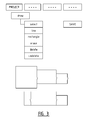
- FIG. 1 illustrates a schematic screen display after starting up an embodiment of the program according to the invention and after selecting a "PROJECT" tab. This display gives a user, typically an installer, the possibility to start a new project, to open an existing project, to save a program, to close the program, to read into a PC a project file saved on a controller, etc.
- a screen When a new project is selected, a screen will appear, such as illustrated in Figure 2 .
- the user is offered the possibility to add a brief description of the project, see "DESCRIPTION" tab in Figure 2 .
- the “PLAN” tab When a user selects the "PLAN” tab, the user is offered an input screen with input functionalities for virtually entering a number of rooms of the building, as illustrated in Figure 3 .
- input functionalities For drawing a floor plan of a floor of the building or of several floors of the building, a number of input functionalities may be offered to the user, such as drawing a line, drawing a rectangle, deleting a line or a rectangle, erasing part of a line or a rectangle, undeleting a certain action, etc. This allows a user to, for example, represent doorways and windows.
- a user may also be offered the possibility to import the floor plan of a house into the program. Subsequently, the designed or imported floor plan may be saved, after which a user can proceed to the next step by selecting the "CREATE" tab.
- Figure 4 shows in a room of the floor plan a number of inputs 1, 1', I", a number of outputs 2, 2', 2" and a number of actions, but the skilled person will understand that when the "CREATE" tab is selected for the first time, this room is still empty.
- the input screen of Figure 4 offers the user the possibility to virtually add an operating means (input) and a device (output).
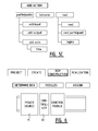
- Operating means include, for example, a single or multiple operating means such as a single or multiple button, a shutter control, a thermostat, a display screen with buttons, a sensor, a touch screen, a smart phone, etc.
- Figure 5B illustrates a list of possible devices, the list comprising for example a lamp, dimmable lamp, a lamp with a dimmer switch, a shutter, a fan, a controllable thermostatic valve, etc..
- the operating means and inputs are means that are provided with a digital address, for example an IP address, allowing them to communicate with one or more controllers on a module assembly site or in the automation system.
- a digital address for example an IP address
- a single or multiple push button will be arranged to send a specific IP address when the button is pressed.
- a motion sensor is arranged to transmit its address the moment a motion is being detected, or a light sensor can be arranged to transmit its IP address in function of the detected amount of light.
- such operating means may also be arranged to transmit certain measurement data to one or more controllers on the module assembly site or in the automation system.
- a device or output is typically a device without intelligence, such as a lamp or a fan intended to be connected to a corresponding module in the module assembly site, which module is addressable.
- a user may virtually link one or more inputs with one or more outputs using the "ADD ACTION" tab, to define the behaviour of a device as a function of the status of one or more operating means linked therewith, wherein the user is given the possibility to incorporate additional conditions.
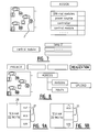
- An example of an input screen is schematically illustrated in Figure 5C .
- a user may add one or more inputs and one or more outputs to an action or a link.
- some form of automation may be added wherein, for example, a start and end time may be set for a certain action.
- the basic behaviour of the added devices or outputs can be set.
- the basic behaviour may, for example, consist in that the lamp lights up the moment the action is started and dims the moment the action stopped.
- additional conditions may be linked to the action.
- the action applies only during a certain time period, for example during winter, or the action may be linked to the status of certain devices that may or may not be linked to the action.
- a user can proceed with planning the construction of the control box by selecting the "BOX CONSTRUCTION" tab as illustrated in Figure 6 .
- a first menu "DETERMINE BOX” a certain type of box may be chosen.
- a power module 11 and a controller module 12 are automatically provided in the virtual control box, as illustrated in Figure 6 .
- the user may further complete the control box with additional modules.
- completing the control box may also be done automatically, wherein, based on the added devices, the program determines which modules are needed in the control box.
- the program knows which devices should be linked with a module and a user will only be able to select these devices in the floor plan, see Figure 7 wherein the lamp 2' is selected by a user after clicking on the switch module.
- a dimmable lamp or a lamp with dimmer can be linked with a dimmer module, a fan with a fan module, etc.
- the IP addresses of the modules and the inputs are read. This may conveniently be realised by entering the inputs in a convenient order to enter and subsequently operate them in this order, such that the inputs transmit their respective IP addresses in this order to the controller which needs to be connected during the construction stage with the computer on which the program is installed.
- the IP addresses may be entered manually. After reading or manually entering the addresses, programming the controller may be effected. This may require the user to select an "UPLOAD" menu in the display screen illustrated in Figure 8 .
- FIG. 9A Another preferred embodiment of a possible operating means will now be described with reference to Figure 9A .
- It concerns a display screen 20 that is integrated into a housing provided with a number of buttons 21, in the illustrated example three buttons called “nxt", “eco” and “sim".
- the "eco” button will allow a user with one push of a button to switch over to an efficient energy consumption wherein, for example, all lights and circuits of a house are switched off.
- the ventilation and heating can be set to a lower level using the "eco" button.
- the controller may be programmed such that pushing the "sim" button activates a presence simulation when a resident, for example, is absent or on vacation.
- a presence simulation may imply that, for example, the lights are switched on and off at irregular intervals such that it appears from the outside that the house is occupied.
- a display screen 20 is further provided showing, for example, the instantaneous main consumption of the entire house or the partial consumption of, for example, a chamber.
- This may be the electricity consumption only, but could also be the combined water, gas and electricity consumption.
- the "nxt" button may be programmed to allow a user to scroll through various display screens. In this way, the combination with the "eco” button will ensure an interaction with the user: by pressing the "eco” button, a user immediately observes a decrease in consumption.
- the instantaneous electricity consumption for example, use can be made of a device as described in the patent application on behalf of Applicant entitled "Control box with measuring function, measuring module therefore, and home automation system comprising such a control box", which was filed on January 7, 2011 and which is herein integrally incorporated by reference.
- the devices and methods described in said application will allow to measure the instantaneous total electricity consumption of a house, or to measure the instantaneous consumption in a certain circuit.
- the measurement modules may be linked with software to display the current electricity consumption and electricity consumption as a function of time, the differences between different electricity rates (day/night) and a comparison between the different usage periods.
- Such information can, for example, be displayed on a touch screen, PC or a smart phone.
- a special application can be provided.
- such an application may also permit a resident to set certain objectives in terms of its energy consumption. When the energy consumption exceeds these objectives, a user can be informed appropriately. For example, a gas and water measurement may occur based on a pulse count.
- custom measuring modules may be provided in the control box, which are linked with the gas meter and water meter. These modules can then in turn communicate through the communication system, typically a bus, and in particular a non-polarized 2-wire bus, with the display screen 20 to display thereon the gas and water consumption.
- FIG. 9B An embodiment of the operating means of Figure 9A is shown in Figure 9B .
- a first button labelled “eco” activates the eco function when held down and a scroll function for different displays of energy when pressed briefly.
- the middle button is a confirmation button.
- the third button labelled “sim” activates the sim function described above when held down and a scroll function when pressed briefly.
- the scroll function is meant here to scroll between the displays of energy in a reverse order compared with the scroll function of the first button. Note that still other embodiments are conceivable with more or less than three buttons that may or may not have a different function when the buttons are held down or pressed briefly.
Abstract
Description
- The present invention relates to a method for preparing or completing an installation of an automation or home automation system in a building or the like. The invention further relates to a computer program for use in performing such a method and a computer medium for storing program instructions of such a computer program.
- An automation system is typically a system designed for operating a number of devices by means of modules on a module assembly site, typically in at least one control box or by using modules distributed within the automation system and by means of operating means such as a button or a sensor. These operating means are typically provided with an IP address and arranged to communicate via a communication system, such as a bus, but it could also be a wireless communication system. The devices are electrical loads which are typically not provided with intelligence. According to the methods of the prior art, one usually starts thinking starting from the control box. This means that initially the necessary components will be provided in the control box and from there the necessary connections with the equipment and operating means are realized. Also, in the computer programs used to program a home automation system, one may start from the virtual control box from where virtual links are realized with the equipment and operating means.
- The present invention aims to provide a method of the type mentioned in the introduction which is more user-friendly, and allows to install in a more organized way an automation or home automation system.
- To this end, the method according to the invention is characterized in that it includes:
- providing on a display to a user an input screen with input functionalities for virtually entering a number of rooms of the building and for virtually adding to each room on the one hand devices and on the other hand operating means thereof;
- providing on a display to the user a linking functionality for creating a virtual link between one or more added operating means and one or more added input devices;
- automatically reading the devices added by the user and automatically selecting those devices which need to be connected with a module on the module assembly site, typically in the at least one control box or module distributed within the automation system. Note that the operating means typically do not require a connection with a module in the module assembly site. In the event that this is the case anyway, one may also select the appropriate operating means according to the method according to the invention.
- In the context of the present invention, the expression "home automation system" is to be understood to comprise both a domestic automation system as an automation system in an industrial building. More generally, a home automation system in any building may be provided with electrical devices.
- The method according to the invention does not depart from the control box but from virtually providing devices and operating means in virtual rooms of a building and creating virtual links between them. This will allow a user, typically an installer, to first determine which devices and operating means he desires in the building and then proceeds to determining the elements needed in the module assembly site and to the programming thereof, see below.
- According to a preferred embodiment, creating a link between one or more added operating means and/or sensors and one or more added devices comprises defining the behaviour of the one or more linked devices depending as function the status of the one or more operating means. This allows a user to determine what a device is supposed to do the moment a operating means measures or detects a particular input, for example, pressing a button, measuring a certain temperature, the measurement of a movement, etc.
- According to a preferred embodiment, offering to the user the linking functionality, comprises providing an input screen for inputting one or more conditions to define the behaviour. For such a behaviour could only need to take place in a certain time period, for example during daytime, or if another device is in a particular status. Other criteria, for example, could be the intensity of the light or the intensity of the wind measured by a operating means, and hence, a condition could use, for example, time, light intensity and wind intensity. If the one or more conditions are not met, optionally any other behaviour can be defined. According to a preferred embodiment, one condition is used and a first behaviour can be defined if the condition is met, and optionally a second behaviour can be defined if the condition is not met.
- According to an preferred embodiment, the method further comprises offering to the user an input screen with input functionalities for adding a number of modules designed to be installed on the module assembly site, typically in the at least one control box or distributed in the system. Preferably, the user is further offered an input screen with input functionalities for creating a link between an added module and one or more selected devices.
- According to another embodiment, the method further comprises automatically determining a number of modules for installation on the module assembly site, typically in the control box, based on the selected devices. In this way, a user does no longer need to choose for himself the appropriate modules, but they are automatically installed in the virtual module assembly site. The method may further comprise automatically creating a link between a particular module and one or more selected devices. In this way, the user is provided with a complete floor plan of the module assembly site based on the devices and connection means provided by him.
- According to a preferred embodiment, the method further comprises the physical installation of the added operating means and devices. Next, the modules in the module assembly site can physically be mounted based on the automatically determined or added number of modules and the modules can be electrically connected to each of the selected devices based on the determined or added virtual links between a module and one or more selected devices.
- Each operating means and each module typically has a digital address, for example an IP address, and is able to communicate with one or more controllers or control units on the module assembly site by means of a communication system or distributed within the system, typically a bus, for example, a 2-wire non-polarized bus. Hence, the method may comprise providing on a display to a user an input screen with input functionalities for entering the operating means and modules, and for reading out the digital addresses thereof, and for storing the digital addresses read out for use by one or more controllers, centrally or decentrally installed. After entering of the virtual rooms with devices, operating means and links between them, after constructing the virtual module assembly site, and after the physical installation thereof, one can subsequently read out the addresses of the operating means and modules with the method according to the invention. According to another embodiment, one can manually retype the addresses of the elements of the physical installation under construction to construct it afterwards.
- According to the preferred embodiment, providing on a display an input screen with input functionalities for entering a number of rooms of the building, comprises providing a graphical interface wherein the user is able to draw a floor plan of the building using lines and/or shapes. This will further improve the ergonomics of the method. Providing on a display an input screen with input functionalities for adding to each room on the one hand devices and on the other hand operating means thereof consists preferably of providing the possibility to place icons for these devices and operating means on the floor plan.
- The devices may include one or more of the following: a dimmer switch, a shutter, a controllable thermostatic valve, a fan, a lamp.
- The operating means may include one or more of the following: a single or multiple control, such as a single or multiple button, a shutter control, a thermostat, a display screen with buttons, a sensor, a touch screen, a smart phone, etc..
- The modules may include one or more of the following: a controller, a power supply, a switching device, a dimmer module, a fan module, a heating module and they can be centrally installed or distributed within the automation system.
- The invention further provides a computer medium for storing program instructions for use in performing an embodiment of a method as described above.
- The invention also relates to a computer program for use in performing an embodiment of a method as described above.
- Finally, the invention relates to an automation system with one or more controllers or controller units, centrally or decentrally in the automation system for controlling operating means and control box modules; a measuring module for measuring the instantaneous electrical power consumption in at least one circuit, an operating means with a display screen and at least one button. The operating means is arranged to receive and display on the display screen the measured electrical power consumption. The one or more central or decentralized controllers are arranged to control - after pressing a button on the operating means - certain other operating means and/or control box modules of the automation or home automation system in a programmed way. The invention also relates to such an operating means per se and the use thereof in an automation system as described above. Such an operating means has the advantage that a user is able to immediately perceive - when pressing a button - the effect on the electrical power consumption in the least one circuit. Preferred additional measures of such operating means are described below with reference to
Figure 9A and 9B and the skilled person will understand that these additional measures may individually be combined with the operating means described in this paragraph. - The present invention will be illustrated by means of a by no means limiting embodiment of the method and computer program according to the invention with reference to the attached drawings. The drawing shows:
- In
Figure 1 , a schematic representation of the display when starting up an embodiment of the computer program according to the invention; - In
Figure 2 , a schematic representation of the display after selecting the "PROJECT" tab ofFigure 1 ; - In
Figure 3 , a schematic representation of the display after selecting the "PLAN" tab ofFigure 2 ; - In
Figure 4 , a schematic representation of the display after selecting the "CREATE" tab ofFigure 1 , after adding a number of inputs, outputs and actions; - In
Figure 5A , a schematic representation of the display after selecting the "ADD INPUT" tab ofFigure 4 ; - In
Figure 5B , a schematic representation of the display after selecting the "ADD OUTPUT" tab ofFigure 4 ; - In
Figure 5C , a schematic representation of the display after selecting the "ADD ACTION" tab ofFigure 4 , also displaying a number of submenus; - In
Figure 6 , a schematic representation of the display after selecting the "BOX CONSTRUCTION" tab ofFigure 1 ; - In
Figure 7 , a schematic representation of the display after selecting the "ASSIGN" tab ofFigure 6 , after assigning an output to a module and a schematic representation of a portion of the display after selecting the switch module; - In
Figure 8 , a schematic representation of the display after selecting the "CREATE" tab ofFigure 1 ; - In
Figure 9 , a schematic view of an embodiment of a preferred operating means according to the invention. - An embodiment of the method according to the invention is designed to prepare the installation of an automation or home automation system in a building, typically a house or similar. Note that the method can be used as a tool when the electrical devices and circuits have already been installed partially or in full or when the installation is yet to take place or when certain devices and/or operating means need to be added.
Figure 1 illustrates a schematic screen display after starting up an embodiment of the program according to the invention and after selecting a "PROJECT" tab. This display gives a user, typically an installer, the possibility to start a new project, to open an existing project, to save a program, to close the program, to read into a PC a project file saved on a controller, etc. - When a new project is selected, a screen will appear, such as illustrated in
Figure 2 . Here, the user is offered the possibility to add a brief description of the project, see "DESCRIPTION" tab inFigure 2 . When a user selects the "PLAN" tab, the user is offered an input screen with input functionalities for virtually entering a number of rooms of the building, as illustrated inFigure 3 . For drawing a floor plan of a floor of the building or of several floors of the building, a number of input functionalities may be offered to the user, such as drawing a line, drawing a rectangle, deleting a line or a rectangle, erasing part of a line or a rectangle, undeleting a certain action, etc. This allows a user to, for example, represent doorways and windows. According to a non-illustrated embodiment, a user may also be offered the possibility to import the floor plan of a house into the program. Subsequently, the designed or imported floor plan may be saved, after which a user can proceed to the next step by selecting the "CREATE" tab. - An example of a display screen after selecting the "CREATE" tab is schematically illustrated in
Figure 4. Figure 4 shows in a room of the floor plan a number ofinputs 1, 1', I", a number ofoutputs Figure 4 offers the user the possibility to virtually add an operating means (input) and a device (output). - By clicking on the "ADD INPUT" tab, the user is presented, for example, with the list as illustrated in
Figure 5A , from which the user may select an operation means or input. Operating means include, for example, a single or multiple operating means such as a single or multiple button, a shutter control, a thermostat, a display screen with buttons, a sensor, a touch screen, a smart phone, etc. Analogously, by selecting the "ADD OUTPUT" tab, a user may add one or more outputs or devices to a room.Figure 5B illustrates a list of possible devices, the list comprising for example a lamp, dimmable lamp, a lamp with a dimmer switch, a shutter, a fan, a controllable thermostatic valve, etc.. The operating means and inputs are means that are provided with a digital address, for example an IP address, allowing them to communicate with one or more controllers on a module assembly site or in the automation system. Hence, a single or multiple push button will be arranged to send a specific IP address when the button is pressed. Analogously, a motion sensor is arranged to transmit its address the moment a motion is being detected, or a light sensor can be arranged to transmit its IP address in function of the detected amount of light. In addition to transmitting their IP address, such operating means may also be arranged to transmit certain measurement data to one or more controllers on the module assembly site or in the automation system. A device or output is typically a device without intelligence, such as a lamp or a fan intended to be connected to a corresponding module in the module assembly site, which module is addressable. - After entering the operating means (hereinafter also called inputs) and devices (hereinafter also called outputs), a user may virtually link one or more inputs with one or more outputs using the "ADD ACTION" tab, to define the behaviour of a device as a function of the status of one or more operating means linked therewith, wherein the user is given the possibility to incorporate additional conditions. An example of an input screen is schematically illustrated in
Figure 5C . In a first menu "PARTICIPANTS" a user may add one or more inputs and one or more outputs to an action or a link. Furthermore, some form of automation may be added wherein, for example, a start and end time may be set for a certain action. In a next menu "BEHAVIOR", the basic behaviour of the added devices or outputs can be set. For a lamp, the basic behaviour may, for example, consist in that the lamp lights up the moment the action is started and dims the moment the action stopped. In a further menu "CONDITION", additional conditions may be linked to the action. Herein, one may specify that the action applies only during a certain time period, for example during winter, or the action may be linked to the status of certain devices that may or may not be linked to the action. Furthermore, it is possible to define an abnormal behaviour in the event that the condition is not met. For example, one can specify that an action is performed according to a first behaviour if the light in an adjacent room is out, and according to a second behaviour if the light in an adjacent room is on. Note that it is possible to add devices in different rooms to the same action, and that not all devices need to appear in both behaviours. - After entering all operating means and devices, and after entering the desired actions, a user can proceed with planning the construction of the control box by selecting the "BOX CONSTRUCTION" tab as illustrated in
Figure 6 . In a first menu "DETERMINE BOX", a certain type of box may be chosen. According to a preferred embodiment, apower module 11 and acontroller module 12 are automatically provided in the virtual control box, as illustrated inFigure 6 . In the menu "MODULES" the user may further complete the control box with additional modules. According to a possible option, completing the control box may also be done automatically, wherein, based on the added devices, the program determines which modules are needed in the control box. Note that it is preferred to offer to a user the possibility to be able to change a auto-filled virtual control box, taking into account, for example, future extensions. In the event the control box with modules has already been installed, it will be preferred to add the modules manually in the order the modules are mounted in the control box. Subsequently, in the "ASSIGN" menu, a user may virtually connect certain devices to the added modules. This is illustrated inFigure 7 . The program is designed to automatically read the devices entered by the user and to automatically select the connected devices thereof which need to be linked with a module in the control box. Hence, the program knows which devices should be linked with a module and a user will only be able to select these devices in the floor plan, seeFigure 7 wherein the lamp 2' is selected by a user after clicking on the switch module. In an analogous manner, for example, a dimmable lamp or a lamp with dimmer can be linked with a dimmer module, a fan with a fan module, etc. - After performing the virtual creation and virtual box construction, and after actually installing the various operating means and devices, and after actually mounting the various modules in the control box based on the virtual plan of the control box that was generated as mentioned above, one may proceed to the actual programming of the controller in the control box. To this end, a user may select the "REALIZATION" tab, as illustrated in
Figure 8 . Herein, in a first step, the IP addresses of the modules and the inputs are read. This may conveniently be realised by entering the inputs in a convenient order to enter and subsequently operate them in this order, such that the inputs transmit their respective IP addresses in this order to the controller which needs to be connected during the construction stage with the computer on which the program is installed. According to an embodiment thereof, the IP addresses may be entered manually. After reading or manually entering the addresses, programming the controller may be effected. This may require the user to select an "UPLOAD" menu in the display screen illustrated inFigure 8 . - Another preferred embodiment of a possible operating means will now be described with reference to
Figure 9A . It concerns adisplay screen 20 that is integrated into a housing provided with a number ofbuttons 21, in the illustrated example three buttons called "nxt", "eco" and "sim". The "eco" button will allow a user with one push of a button to switch over to an efficient energy consumption wherein, for example, all lights and circuits of a house are switched off. For example, also the ventilation and heating can be set to a lower level using the "eco" button. - Furthermore, the controller may be programmed such that pushing the "sim" button activates a presence simulation when a resident, for example, is absent or on vacation. Such a presence simulation may imply that, for example, the lights are switched on and off at irregular intervals such that it appears from the outside that the house is occupied.
- To draw a user's attention to its consumption, a
display screen 20 is further provided showing, for example, the instantaneous main consumption of the entire house or the partial consumption of, for example, a chamber. This may be the electricity consumption only, but could also be the combined water, gas and electricity consumption. The "nxt" button may be programmed to allow a user to scroll through various display screens. In this way, the combination with the "eco" button will ensure an interaction with the user: by pressing the "eco" button, a user immediately observes a decrease in consumption. To measure the instantaneous electricity consumption, for example, use can be made of a device as described in the patent application on behalf of Applicant entitled "Control box with measuring function, measuring module therefore, and home automation system comprising such a control box", which was filed on January 7, 2011 and which is herein integrally incorporated by reference. The devices and methods described in said application will allow to measure the instantaneous total electricity consumption of a house, or to measure the instantaneous consumption in a certain circuit. As is also described in said application, the measurement modules may be linked with software to display the current electricity consumption and electricity consumption as a function of time, the differences between different electricity rates (day/night) and a comparison between the different usage periods. Such information can, for example, be displayed on a touch screen, PC or a smart phone. For a smart phone, to this end, a special application can be provided. Furthermore, such an application, for example, may also permit a resident to set certain objectives in terms of its energy consumption. When the energy consumption exceeds these objectives, a user can be informed appropriately. For example, a gas and water measurement may occur based on a pulse count. To this end, custom measuring modules may be provided in the control box, which are linked with the gas meter and water meter. These modules can then in turn communicate through the communication system, typically a bus, and in particular a non-polarized 2-wire bus, with thedisplay screen 20 to display thereon the gas and water consumption. - An embodiment of the operating means of
Figure 9A is shown inFigure 9B . A first button labelled "eco" activates the eco function when held down and a scroll function for different displays of energy when pressed briefly. The middle button is a confirmation button. The third button labelled "sim" activates the sim function described above when held down and a scroll function when pressed briefly. The scroll function is meant here to scroll between the displays of energy in a reverse order compared with the scroll function of the first button. Note that still other embodiments are conceivable with more or less than three buttons that may or may not have a different function when the buttons are held down or pressed briefly. - The skilled person will appreciate that the invention is not limited to the embodiments of the method and computer program according to the invention given above and that many additions and embodiments are conceivable within the context of the invention which is only determined by the appended claims.
Claims (15)
- Method for preparing or completing an installation of an automation system in a building or the like, which automation system is intended to control a number of devices by means of operating means and modules on a module assembly site or distributed within the automation system, which method comprises:- providing on a display to a user an input screen with input functionalities for virtually entering a number of rooms of the building and for virtually adding to each room on the one hand devices and on the other hand operating means thereof;- providing on a display to the user a linking functionality for creating a virtual link between one or more added operating means and one or more added input devices;- automatically reading the devices added by the user and automatically selecting those devices which need to be connected with a module on the module assembly site or a module distributed within the automation system.
- Method according to claim 1, characterized in that creating the link between one or more added operating means and one or more added devices comprises defining the behaviour of the one or more linked devices depending as function the status of the one or more operating means.
- Method according to claim 2, characterized in that offering to the user the linking functionality, comprises providing an input screen for inputting one or more conditions to define the behaviour.
- Method according to any one of the preceding claims, further comprising offering to the user an input screen with input functionalities for adding a number of modules designed to be installed on the module assembly site, and/or for creating a link between an added module and one or more selected devices.
- Method according to any one of the preceding claims, further comprising automatically determining a number of modules for installation on the module assembly site based on the selected devices, preferably comprising automatically creating a link between a particular module and one or more selected devices.
- Method according to any one of the preceding claims, further comprising the installation of the added operating means and devices.
- Method according to claim 6, further comprising mounting the modules in the module assembly site based on the determined or added number of modules and electrically connecting each of the selected devices based on a determined or added links between a module and one or more selected devices.
- Method according to claim 7, wherein each operating means and each module has a digital address and is able to communicate with a controller in the module assembly site or with a controller distributed within the automation system by means of a communication system, further comprising providing on a display to a user an input screen with input functionalities for entering the operating means and modules, and for reading out the digital addresses thereof, and for storing the digital addresses read out for use by the controller.
- Method according to any one of the preceding claims, characterized in that providing on a display an input screen with input functionalities to a user for entering a number of rooms of the building, essentially comprises providing a graphical interface wherein the user is able to draw a floor plan of the building using lines and/or shapes.
- Method according to any one of the preceding claims, characterized in that a screen offering an input with input features for each room adding devices one hand and operating means of other mainly consists of providing the opportunity to icons for these devices and operating means to place in the floor plan.
- Method according to any one of the preceding claims, characterized in that the devices may include one or more of the following: a dimmer, a shutter, a controllable thermostatic valve, a fan, a lamp; and/or in that the operating means comprise one or more of the following operating means: a single or multiple control, such as a single or multiple button, a shutter control, a thermostat, a display screen with buttons, a sensor, a touch screen, a smart phone; and/or in that the modules for the module assembly site or the modules distributed within the automation system may comprise one or more of the following modules: a controller, a power supply, a switching device, a dimmer module, a fan module, a heating module.
- Method for preparing or completing an installation of an automation system in a building or the like, which automation system is intended to control a number of devices by means of modules on a module assembly site and operating means, which method comprises:- providing on a display to a user an input screen with input functionalities- for virtually entering a number of rooms of the building wherein a graphical interface is provided wherein the user is able to draw a floor plan of the building using lines and/or shapes; and- for virtually adding to each room on the one hand devices and on the other hand operating means thereof; wherein the possibility is offered to place icons for these devices and operating means on the floor plan;- providing on a display to the user a linking functionality for creating a virtual link between one or more added operating means and one or more added input devices.
- Method according to claim 12, characterized in that creating the link between one or more added operating means and one or more added devices comprises defining the behaviour of the one or more linked devices depending as function the status of the one or more operating means, wherein offering to the user the linking functionality preferably comprises providing an input screen for inputting one or more conditions to define the behaviour.
- Computer medium for storing program instructions for performing the method according to any one of the preceding claims.
- Automation system comprising:- one or more central or decentralized controllers for controlling operating means and control box modules;- a measuring module for measuring the instantaneous electrical power consumption in at least one circuit;- an operating means with a display screen and at least one button, which operating means is arranged to receive and display on the display screen the measured electrical power consumption, wherein the one or more central or decentralized controllers are arranged to control - after pressing a button of the at least one button - certain operating means and/or control box modules in a programmed way.
Priority Applications (1)
| Application Number | Priority Date | Filing Date | Title |
|---|---|---|---|
| PL12152110T PL2482152T3 (en) | 2011-01-28 | 2012-01-23 | Method for use in installing a home automation system, computer medium and computer program |
Applications Claiming Priority (1)
| Application Number | Priority Date | Filing Date | Title |
|---|---|---|---|
| BE2011/0053A BE1019783A3 (en) | 2011-01-28 | 2011-01-28 | METHOD FOR USE IN INSTALLATION OF A DOMOTIC SYSTEM, COMPUTER MEDIUM AND COMPUTER PROGRAM. |
Publications (2)
| Publication Number | Publication Date |
|---|---|
| EP2482152A1 true EP2482152A1 (en) | 2012-08-01 |
| EP2482152B1 EP2482152B1 (en) | 2019-05-15 |
Family
ID=43928913
Family Applications (1)
| Application Number | Title | Priority Date | Filing Date |
|---|---|---|---|
| EP12152110.8A Active EP2482152B1 (en) | 2011-01-28 | 2012-01-23 | Method for use in installing a home automation system, computer medium and computer program |
Country Status (5)
| Country | Link |
|---|---|
| EP (1) | EP2482152B1 (en) |
| BE (1) | BE1019783A3 (en) |
| DK (1) | DK2482152T3 (en) |
| HU (1) | HUE044309T2 (en) |
| PL (1) | PL2482152T3 (en) |
Cited By (6)
| Publication number | Priority date | Publication date | Assignee | Title |
|---|---|---|---|---|
| CN105137798A (en) * | 2015-09-06 | 2015-12-09 | 泉州施米德智能科技有限公司 | System and method for displaying intelligent house in a virtual-actual combination way |
| CN105323123A (en) * | 2014-05-29 | 2016-02-10 | 青岛海尔洗衣机有限公司 | Internet-of-things home appliance and communication method thereof |
| EP3352421A1 (en) | 2017-01-24 | 2018-07-25 | Niko NV | Device location management for automated electrical installation |
| EP3352420A1 (en) | 2017-01-24 | 2018-07-25 | Niko NV | Portable configuration package for programmable electrical system |
| EP3352422A1 (en) * | 2017-01-24 | 2018-07-25 | Niko NV | Configuration of programmed behavior in electrical system |
| CN110168454A (en) * | 2017-02-21 | 2019-08-23 | 欧姆龙株式会社 | For controlling the method and control device of field device |
Citations (7)
| Publication number | Priority date | Publication date | Assignee | Title |
|---|---|---|---|---|
| WO2002058030A2 (en) * | 2001-01-18 | 2002-07-25 | Square D Company | Remote metering display with motion sensor |
| US20040143428A1 (en) * | 2003-01-22 | 2004-07-22 | Rappaport Theodore S. | System and method for automated placement or configuration of equipment for obtaining desired network performance objectives |
| DE102004005219A1 (en) * | 2004-02-03 | 2005-08-18 | Baumgärtner, Udo | Device for automation of building technology |
| DE102004005962A1 (en) * | 2004-02-06 | 2005-08-25 | Angelika Berthold | Building automation system has a central control system that is joined to supply unit via signal lines so that the supply units can be individually controlled by the central control system |
| EP2098928A1 (en) * | 2008-03-07 | 2009-09-09 | Sick Ag | Method and device for programming and/or configuring a safety controller |
| EP2098926A1 (en) * | 2008-03-07 | 2009-09-09 | Sick Ag | Method and device for programming and/or configuring a safety controller |
| EP2180388A1 (en) * | 2008-10-23 | 2010-04-28 | Schneider Electric Industries SAS | Method for projecting a bus-oriented programmable electric installation |
-
2011
- 2011-01-28 BE BE2011/0053A patent/BE1019783A3/en not_active IP Right Cessation
-
2012
- 2012-01-23 HU HUE12152110 patent/HUE044309T2/en unknown
- 2012-01-23 EP EP12152110.8A patent/EP2482152B1/en active Active
- 2012-01-23 PL PL12152110T patent/PL2482152T3/en unknown
- 2012-01-23 DK DK12152110.8T patent/DK2482152T3/en active
Patent Citations (7)
| Publication number | Priority date | Publication date | Assignee | Title |
|---|---|---|---|---|
| WO2002058030A2 (en) * | 2001-01-18 | 2002-07-25 | Square D Company | Remote metering display with motion sensor |
| US20040143428A1 (en) * | 2003-01-22 | 2004-07-22 | Rappaport Theodore S. | System and method for automated placement or configuration of equipment for obtaining desired network performance objectives |
| DE102004005219A1 (en) * | 2004-02-03 | 2005-08-18 | Baumgärtner, Udo | Device for automation of building technology |
| DE102004005962A1 (en) * | 2004-02-06 | 2005-08-25 | Angelika Berthold | Building automation system has a central control system that is joined to supply unit via signal lines so that the supply units can be individually controlled by the central control system |
| EP2098928A1 (en) * | 2008-03-07 | 2009-09-09 | Sick Ag | Method and device for programming and/or configuring a safety controller |
| EP2098926A1 (en) * | 2008-03-07 | 2009-09-09 | Sick Ag | Method and device for programming and/or configuring a safety controller |
| EP2180388A1 (en) * | 2008-10-23 | 2010-04-28 | Schneider Electric Industries SAS | Method for projecting a bus-oriented programmable electric installation |
Cited By (9)
| Publication number | Priority date | Publication date | Assignee | Title |
|---|---|---|---|---|
| CN105323123A (en) * | 2014-05-29 | 2016-02-10 | 青岛海尔洗衣机有限公司 | Internet-of-things home appliance and communication method thereof |
| CN105137798A (en) * | 2015-09-06 | 2015-12-09 | 泉州施米德智能科技有限公司 | System and method for displaying intelligent house in a virtual-actual combination way |
| CN105137798B (en) * | 2015-09-06 | 2017-08-15 | 泉州施米德智能科技有限公司 | Smart home display systems and method that a kind of actual situation is combined |
| EP3352421A1 (en) | 2017-01-24 | 2018-07-25 | Niko NV | Device location management for automated electrical installation |
| EP3352420A1 (en) | 2017-01-24 | 2018-07-25 | Niko NV | Portable configuration package for programmable electrical system |
| EP3352422A1 (en) * | 2017-01-24 | 2018-07-25 | Niko NV | Configuration of programmed behavior in electrical system |
| BE1024936B1 (en) * | 2017-01-24 | 2018-08-27 | Niko Naamloze Vennootschap | Configuration of programmed behavior in electrical system |
| CN110168454A (en) * | 2017-02-21 | 2019-08-23 | 欧姆龙株式会社 | For controlling the method and control device of field device |
| CN110168454B (en) * | 2017-02-21 | 2022-05-06 | 欧姆龙株式会社 | Method for controlling a field device, control device, technical system and storage medium |
Also Published As
| Publication number | Publication date |
|---|---|
| DK2482152T3 (en) | 2019-06-11 |
| HUE044309T2 (en) | 2019-10-28 |
| BE1019783A3 (en) | 2012-12-04 |
| EP2482152B1 (en) | 2019-05-15 |
| PL2482152T3 (en) | 2019-08-30 |
Similar Documents
| Publication | Publication Date | Title |
|---|---|---|
| EP2482152B1 (en) | Method for use in installing a home automation system, computer medium and computer program | |
| US20170336770A1 (en) | System and method for conrolling energy consuming devices within a building | |
| JP6306727B2 (en) | Smart home scene switching method and system | |
| US9541300B2 (en) | HVAC controller with user-friendly installation features facilitating both do-it-yourself and professional installation scenarios | |
| CA2851367C (en) | Hvac controller with user-friendly installation features facilitating both do-it-yourself and professional installation scenarios | |
| US8544285B2 (en) | HVAC controller with user-friendly installation features facilitating both do-it-yourself and professional installation scenarios | |
| CA2752987C (en) | Low cost and flexible energy management system with a scheduling capability | |
| KR101970029B1 (en) | Automated demand response system | |
| US20150168933A1 (en) | System and method for configuring a schedule | |
| US9916631B2 (en) | Multi-purpose electronic switch | |
| KR20150038978A (en) | heating, ventilation, and/or air conditioning controller | |
| EP2482150A1 (en) | Method and device for simplifying electrical installations | |
| CN106597863A (en) | System for dynamic control with interactive visualization to optimize energy consumption | |
| JP2010213367A (en) | Energy saving system using ubiquitous sensor and intelligent table tap | |
| CN106687872A (en) | Method for data collection for the configuration of a building automation system and method for configuring a building automation system | |
| EP3213166A1 (en) | System and apparatus for temperature control | |
| KR102091639B1 (en) | Automatic building control system and control method thereof | |
| EP2482151B1 (en) | Method and device for improving electrical installations | |
| JP6846631B2 (en) | Programs, information terminal device control methods, display systems, terminal control devices, and display devices | |
| KR102486811B1 (en) | Smart switch provided in wall of room of a building for illumination light |
Legal Events
| Date | Code | Title | Description |
|---|---|---|---|
| PUAI | Public reference made under article 153(3) epc to a published international application that has entered the european phase |
Free format text: ORIGINAL CODE: 0009012 |
|
| AK | Designated contracting states |
Kind code of ref document: A1 Designated state(s): AL AT BE BG CH CY CZ DE DK EE ES FI FR GB GR HR HU IE IS IT LI LT LU LV MC MK MT NL NO PL PT RO RS SE SI SK SM TR |
|
| AX | Request for extension of the european patent |
Extension state: BA ME |
|
| 17P | Request for examination filed |
Effective date: 20130130 |
|
| STAA | Information on the status of an ep patent application or granted ep patent |
Free format text: STATUS: EXAMINATION IS IN PROGRESS |
|
| 17Q | First examination report despatched |
Effective date: 20161020 |
|
| GRAP | Despatch of communication of intention to grant a patent |
Free format text: ORIGINAL CODE: EPIDOSNIGR1 |
|
| STAA | Information on the status of an ep patent application or granted ep patent |
Free format text: STATUS: GRANT OF PATENT IS INTENDED |
|
| INTG | Intention to grant announced |
Effective date: 20181205 |
|
| GRAS | Grant fee paid |
Free format text: ORIGINAL CODE: EPIDOSNIGR3 |
|
| GRAA | (expected) grant |
Free format text: ORIGINAL CODE: 0009210 |
|
| STAA | Information on the status of an ep patent application or granted ep patent |
Free format text: STATUS: THE PATENT HAS BEEN GRANTED |
|
| AK | Designated contracting states |
Kind code of ref document: B1 Designated state(s): AL AT BE BG CH CY CZ DE DK EE ES FI FR GB GR HR HU IE IS IT LI LT LU LV MC MK MT NL NO PL PT RO RS SE SI SK SM TR |
|
| REG | Reference to a national code |
Ref country code: CH Ref legal event code: EP Ref country code: GB Ref legal event code: FG4D |
|
| REG | Reference to a national code |
Ref country code: CH Ref legal event code: NV Representative=s name: TR-IP CONSULTING LLC, CH |
|
| REG | Reference to a national code |
Ref country code: DE Ref legal event code: R096 Ref document number: 602012060079 Country of ref document: DE |
|
| REG | Reference to a national code |
Ref country code: DK Ref legal event code: T3 Effective date: 20190604 Ref country code: SE Ref legal event code: TRGR |
|
| REG | Reference to a national code |
Ref country code: IE Ref legal event code: FG4D |
|
| REG | Reference to a national code |
Ref country code: NL Ref legal event code: FP |
|
| REG | Reference to a national code |
Ref country code: NO Ref legal event code: T2 Effective date: 20190515 |
|
| REG | Reference to a national code |
Ref country code: SK Ref legal event code: T3 Ref document number: E 31095 Country of ref document: SK |
|
| REG | Reference to a national code |
Ref country code: LT Ref legal event code: MG4D |
|
| REG | Reference to a national code |
Ref country code: HU Ref legal event code: AG4A Ref document number: E044309 Country of ref document: HU |
|
| PG25 | Lapsed in a contracting state [announced via postgrant information from national office to epo] |
Ref country code: PT Free format text: LAPSE BECAUSE OF FAILURE TO SUBMIT A TRANSLATION OF THE DESCRIPTION OR TO PAY THE FEE WITHIN THE PRESCRIBED TIME-LIMIT Effective date: 20190915 Ref country code: ES Free format text: LAPSE BECAUSE OF FAILURE TO SUBMIT A TRANSLATION OF THE DESCRIPTION OR TO PAY THE FEE WITHIN THE PRESCRIBED TIME-LIMIT Effective date: 20190515 Ref country code: LT Free format text: LAPSE BECAUSE OF FAILURE TO SUBMIT A TRANSLATION OF THE DESCRIPTION OR TO PAY THE FEE WITHIN THE PRESCRIBED TIME-LIMIT Effective date: 20190515 Ref country code: FI Free format text: LAPSE BECAUSE OF FAILURE TO SUBMIT A TRANSLATION OF THE DESCRIPTION OR TO PAY THE FEE WITHIN THE PRESCRIBED TIME-LIMIT Effective date: 20190515 Ref country code: HR Free format text: LAPSE BECAUSE OF FAILURE TO SUBMIT A TRANSLATION OF THE DESCRIPTION OR TO PAY THE FEE WITHIN THE PRESCRIBED TIME-LIMIT Effective date: 20190515 Ref country code: AL Free format text: LAPSE BECAUSE OF FAILURE TO SUBMIT A TRANSLATION OF THE DESCRIPTION OR TO PAY THE FEE WITHIN THE PRESCRIBED TIME-LIMIT Effective date: 20190515 |
|
| PG25 | Lapsed in a contracting state [announced via postgrant information from national office to epo] |
Ref country code: RS Free format text: LAPSE BECAUSE OF FAILURE TO SUBMIT A TRANSLATION OF THE DESCRIPTION OR TO PAY THE FEE WITHIN THE PRESCRIBED TIME-LIMIT Effective date: 20190515 Ref country code: LV Free format text: LAPSE BECAUSE OF FAILURE TO SUBMIT A TRANSLATION OF THE DESCRIPTION OR TO PAY THE FEE WITHIN THE PRESCRIBED TIME-LIMIT Effective date: 20190515 Ref country code: GR Free format text: LAPSE BECAUSE OF FAILURE TO SUBMIT A TRANSLATION OF THE DESCRIPTION OR TO PAY THE FEE WITHIN THE PRESCRIBED TIME-LIMIT Effective date: 20190816 Ref country code: BG Free format text: LAPSE BECAUSE OF FAILURE TO SUBMIT A TRANSLATION OF THE DESCRIPTION OR TO PAY THE FEE WITHIN THE PRESCRIBED TIME-LIMIT Effective date: 20190815 |
|
| REG | Reference to a national code |
Ref country code: AT Ref legal event code: MK05 Ref document number: 1134185 Country of ref document: AT Kind code of ref document: T Effective date: 20190515 |
|
| PG25 | Lapsed in a contracting state [announced via postgrant information from national office to epo] |
Ref country code: AT Free format text: LAPSE BECAUSE OF FAILURE TO SUBMIT A TRANSLATION OF THE DESCRIPTION OR TO PAY THE FEE WITHIN THE PRESCRIBED TIME-LIMIT Effective date: 20190515 Ref country code: RO Free format text: LAPSE BECAUSE OF FAILURE TO SUBMIT A TRANSLATION OF THE DESCRIPTION OR TO PAY THE FEE WITHIN THE PRESCRIBED TIME-LIMIT Effective date: 20190515 Ref country code: EE Free format text: LAPSE BECAUSE OF FAILURE TO SUBMIT A TRANSLATION OF THE DESCRIPTION OR TO PAY THE FEE WITHIN THE PRESCRIBED TIME-LIMIT Effective date: 20190515 |
|
| REG | Reference to a national code |
Ref country code: CH Ref legal event code: PCAR Free format text: NEW ADDRESS: ROUTE DU COUTSET 18, 1485 NUVILLY (CH) |
|
| REG | Reference to a national code |
Ref country code: DE Ref legal event code: R097 Ref document number: 602012060079 Country of ref document: DE |
|
| PG25 | Lapsed in a contracting state [announced via postgrant information from national office to epo] |
Ref country code: SM Free format text: LAPSE BECAUSE OF FAILURE TO SUBMIT A TRANSLATION OF THE DESCRIPTION OR TO PAY THE FEE WITHIN THE PRESCRIBED TIME-LIMIT Effective date: 20190515 Ref country code: IT Free format text: LAPSE BECAUSE OF FAILURE TO SUBMIT A TRANSLATION OF THE DESCRIPTION OR TO PAY THE FEE WITHIN THE PRESCRIBED TIME-LIMIT Effective date: 20190515 |
|
| PLBE | No opposition filed within time limit |
Free format text: ORIGINAL CODE: 0009261 |
|
| STAA | Information on the status of an ep patent application or granted ep patent |
Free format text: STATUS: NO OPPOSITION FILED WITHIN TIME LIMIT |
|
| PG25 | Lapsed in a contracting state [announced via postgrant information from national office to epo] |
Ref country code: TR Free format text: LAPSE BECAUSE OF FAILURE TO SUBMIT A TRANSLATION OF THE DESCRIPTION OR TO PAY THE FEE WITHIN THE PRESCRIBED TIME-LIMIT Effective date: 20190515 |
|
| 26N | No opposition filed |
Effective date: 20200218 |
|
| PG25 | Lapsed in a contracting state [announced via postgrant information from national office to epo] |
Ref country code: SI Free format text: LAPSE BECAUSE OF FAILURE TO SUBMIT A TRANSLATION OF THE DESCRIPTION OR TO PAY THE FEE WITHIN THE PRESCRIBED TIME-LIMIT Effective date: 20190515 |
|
| PG25 | Lapsed in a contracting state [announced via postgrant information from national office to epo] |
Ref country code: MC Free format text: LAPSE BECAUSE OF FAILURE TO SUBMIT A TRANSLATION OF THE DESCRIPTION OR TO PAY THE FEE WITHIN THE PRESCRIBED TIME-LIMIT Effective date: 20190515 |
|
| PG25 | Lapsed in a contracting state [announced via postgrant information from national office to epo] |
Ref country code: LU Free format text: LAPSE BECAUSE OF NON-PAYMENT OF DUE FEES Effective date: 20200123 |
|
| PG25 | Lapsed in a contracting state [announced via postgrant information from national office to epo] |
Ref country code: IE Free format text: LAPSE BECAUSE OF NON-PAYMENT OF DUE FEES Effective date: 20200123 |
|
| PGFP | Annual fee paid to national office [announced via postgrant information from national office to epo] |
Ref country code: CZ Payment date: 20210122 Year of fee payment: 10 |
|
| PGFP | Annual fee paid to national office [announced via postgrant information from national office to epo] |
Ref country code: HU Payment date: 20210214 Year of fee payment: 10 |
|
| PG25 | Lapsed in a contracting state [announced via postgrant information from national office to epo] |
Ref country code: MT Free format text: LAPSE BECAUSE OF FAILURE TO SUBMIT A TRANSLATION OF THE DESCRIPTION OR TO PAY THE FEE WITHIN THE PRESCRIBED TIME-LIMIT Effective date: 20190515 Ref country code: CY Free format text: LAPSE BECAUSE OF FAILURE TO SUBMIT A TRANSLATION OF THE DESCRIPTION OR TO PAY THE FEE WITHIN THE PRESCRIBED TIME-LIMIT Effective date: 20190515 |
|
| PG25 | Lapsed in a contracting state [announced via postgrant information from national office to epo] |
Ref country code: MK Free format text: LAPSE BECAUSE OF FAILURE TO SUBMIT A TRANSLATION OF THE DESCRIPTION OR TO PAY THE FEE WITHIN THE PRESCRIBED TIME-LIMIT Effective date: 20190515 Ref country code: IS Free format text: LAPSE BECAUSE OF FAILURE TO SUBMIT A TRANSLATION OF THE DESCRIPTION OR TO PAY THE FEE WITHIN THE PRESCRIBED TIME-LIMIT Effective date: 20190915 |
|
| PG25 | Lapsed in a contracting state [announced via postgrant information from national office to epo] |
Ref country code: CZ Free format text: LAPSE BECAUSE OF NON-PAYMENT OF DUE FEES Effective date: 20220123 |
|
| PG25 | Lapsed in a contracting state [announced via postgrant information from national office to epo] |
Ref country code: HU Free format text: LAPSE BECAUSE OF NON-PAYMENT OF DUE FEES Effective date: 20220124 |
|
| PGFP | Annual fee paid to national office [announced via postgrant information from national office to epo] |
Ref country code: NO Payment date: 20230123 Year of fee payment: 12 Ref country code: FR Payment date: 20230124 Year of fee payment: 12 Ref country code: DK Payment date: 20230123 Year of fee payment: 12 Ref country code: CH Payment date: 20230119 Year of fee payment: 12 |
|
| PGFP | Annual fee paid to national office [announced via postgrant information from national office to epo] |
Ref country code: SK Payment date: 20230113 Year of fee payment: 12 Ref country code: SE Payment date: 20230119 Year of fee payment: 12 Ref country code: PL Payment date: 20230116 Year of fee payment: 12 Ref country code: GB Payment date: 20230119 Year of fee payment: 12 Ref country code: DE Payment date: 20220620 Year of fee payment: 12 Ref country code: BE Payment date: 20230119 Year of fee payment: 12 |
|
| PGFP | Annual fee paid to national office [announced via postgrant information from national office to epo] |
Ref country code: NL Payment date: 20230119 Year of fee payment: 12 |
|
| P01 | Opt-out of the competence of the unified patent court (upc) registered |
Effective date: 20230526 |