EP2477579B1 - Intervertebral implant having extendable bone fixation members - Google Patents
Intervertebral implant having extendable bone fixation members Download PDFInfo
- Publication number
- EP2477579B1 EP2477579B1 EP10759773.4A EP10759773A EP2477579B1 EP 2477579 B1 EP2477579 B1 EP 2477579B1 EP 10759773 A EP10759773 A EP 10759773A EP 2477579 B1 EP2477579 B1 EP 2477579B1
- Authority
- EP
- European Patent Office
- Prior art keywords
- screw
- fixation member
- implant
- fixation
- intervertebral implant
- Prior art date
- Legal status (The legal status is an assumption and is not a legal conclusion. Google has not performed a legal analysis and makes no representation as to the accuracy of the status listed.)
- Active
Links
- 239000007943 implant Substances 0.000 title claims description 140
- 210000000988 bone and bone Anatomy 0.000 title description 10
- 238000013519 translation Methods 0.000 claims description 4
- 239000000463 material Substances 0.000 description 11
- 238000000034 method Methods 0.000 description 6
- 239000004696 Poly ether ether ketone Substances 0.000 description 4
- 230000008468 bone growth Effects 0.000 description 4
- 238000000576 coating method Methods 0.000 description 4
- 238000003780 insertion Methods 0.000 description 4
- 230000037431 insertion Effects 0.000 description 4
- 229920002492 poly(sulfone) Polymers 0.000 description 4
- 229920002530 polyetherether ketone Polymers 0.000 description 4
- 229920000785 ultra high molecular weight polyethylene Polymers 0.000 description 4
- RTAQQCXQSZGOHL-UHFFFAOYSA-N Titanium Chemical compound [Ti] RTAQQCXQSZGOHL-UHFFFAOYSA-N 0.000 description 3
- 230000004927 fusion Effects 0.000 description 3
- 229910052719 titanium Inorganic materials 0.000 description 3
- 239000010936 titanium Substances 0.000 description 3
- 239000000853 adhesive Substances 0.000 description 2
- 230000001070 adhesive effect Effects 0.000 description 2
- 238000013459 approach Methods 0.000 description 2
- 239000011248 coating agent Substances 0.000 description 2
- 230000000295 complement effect Effects 0.000 description 2
- 229910001000 nickel titanium Inorganic materials 0.000 description 2
- 230000001737 promoting effect Effects 0.000 description 2
- 210000000954 sacrococcygeal region Anatomy 0.000 description 2
- 206010061246 Intervertebral disc degeneration Diseases 0.000 description 1
- 229910001069 Ti alloy Inorganic materials 0.000 description 1
- MTHLBYMFGWSRME-UHFFFAOYSA-N [Cr].[Co].[Mo] Chemical compound [Cr].[Co].[Mo] MTHLBYMFGWSRME-UHFFFAOYSA-N 0.000 description 1
- HZEWFHLRYVTOIW-UHFFFAOYSA-N [Ti].[Ni] Chemical compound [Ti].[Ni] HZEWFHLRYVTOIW-UHFFFAOYSA-N 0.000 description 1
- 230000005856 abnormality Effects 0.000 description 1
- 239000000560 biocompatible material Substances 0.000 description 1
- 239000000919 ceramic Substances 0.000 description 1
- 208000018180 degenerative disc disease Diseases 0.000 description 1
- 239000003814 drug Substances 0.000 description 1
- 229940079593 drug Drugs 0.000 description 1
- 230000012010 growth Effects 0.000 description 1
- 229910052588 hydroxylapatite Inorganic materials 0.000 description 1
- 238000002513 implantation Methods 0.000 description 1
- 230000008676 import Effects 0.000 description 1
- 230000002452 interceptive effect Effects 0.000 description 1
- 208000021600 intervertebral disc degenerative disease Diseases 0.000 description 1
- 230000001045 lordotic effect Effects 0.000 description 1
- 210000004705 lumbosacral region Anatomy 0.000 description 1
- 238000012986 modification Methods 0.000 description 1
- 230000004048 modification Effects 0.000 description 1
- HLXZNVUGXRDIFK-UHFFFAOYSA-N nickel titanium Chemical compound [Ti].[Ti].[Ti].[Ti].[Ti].[Ti].[Ti].[Ti].[Ti].[Ti].[Ti].[Ni].[Ni].[Ni].[Ni].[Ni].[Ni].[Ni].[Ni].[Ni].[Ni].[Ni].[Ni].[Ni].[Ni] HLXZNVUGXRDIFK-UHFFFAOYSA-N 0.000 description 1
- 230000000399 orthopedic effect Effects 0.000 description 1
- XYJRXVWERLGGKC-UHFFFAOYSA-D pentacalcium;hydroxide;triphosphate Chemical compound [OH-].[Ca+2].[Ca+2].[Ca+2].[Ca+2].[Ca+2].[O-]P([O-])([O-])=O.[O-]P([O-])([O-])=O.[O-]P([O-])([O-])=O XYJRXVWERLGGKC-UHFFFAOYSA-D 0.000 description 1
- 229920000642 polymer Polymers 0.000 description 1
- 239000007787 solid Substances 0.000 description 1
- 125000006850 spacer group Chemical group 0.000 description 1
- 210000000278 spinal cord Anatomy 0.000 description 1
- 239000010935 stainless steel Substances 0.000 description 1
- 229910001220 stainless steel Inorganic materials 0.000 description 1
- 239000000126 substance Substances 0.000 description 1
- 238000001356 surgical procedure Methods 0.000 description 1
- 210000000115 thoracic cavity Anatomy 0.000 description 1
Images


Classifications
-
- A—HUMAN NECESSITIES
- A61—MEDICAL OR VETERINARY SCIENCE; HYGIENE
- A61F—FILTERS IMPLANTABLE INTO BLOOD VESSELS; PROSTHESES; DEVICES PROVIDING PATENCY TO, OR PREVENTING COLLAPSING OF, TUBULAR STRUCTURES OF THE BODY, e.g. STENTS; ORTHOPAEDIC, NURSING OR CONTRACEPTIVE DEVICES; FOMENTATION; TREATMENT OR PROTECTION OF EYES OR EARS; BANDAGES, DRESSINGS OR ABSORBENT PADS; FIRST-AID KITS
- A61F2/00—Filters implantable into blood vessels; Prostheses, i.e. artificial substitutes or replacements for parts of the body; Appliances for connecting them with the body; Devices providing patency to, or preventing collapsing of, tubular structures of the body, e.g. stents
- A61F2/02—Prostheses implantable into the body
- A61F2/30—Joints
- A61F2/44—Joints for the spine, e.g. vertebrae, spinal discs
- A61F2/4455—Joints for the spine, e.g. vertebrae, spinal discs for the fusion of spinal bodies, e.g. intervertebral fusion of adjacent spinal bodies, e.g. fusion cages
-
- A—HUMAN NECESSITIES
- A61—MEDICAL OR VETERINARY SCIENCE; HYGIENE
- A61F—FILTERS IMPLANTABLE INTO BLOOD VESSELS; PROSTHESES; DEVICES PROVIDING PATENCY TO, OR PREVENTING COLLAPSING OF, TUBULAR STRUCTURES OF THE BODY, e.g. STENTS; ORTHOPAEDIC, NURSING OR CONTRACEPTIVE DEVICES; FOMENTATION; TREATMENT OR PROTECTION OF EYES OR EARS; BANDAGES, DRESSINGS OR ABSORBENT PADS; FIRST-AID KITS
- A61F2/00—Filters implantable into blood vessels; Prostheses, i.e. artificial substitutes or replacements for parts of the body; Appliances for connecting them with the body; Devices providing patency to, or preventing collapsing of, tubular structures of the body, e.g. stents
- A61F2/02—Prostheses implantable into the body
- A61F2/30—Joints
- A61F2/30721—Accessories
- A61F2/30749—Fixation appliances for connecting prostheses to the body
-
- A—HUMAN NECESSITIES
- A61—MEDICAL OR VETERINARY SCIENCE; HYGIENE
- A61F—FILTERS IMPLANTABLE INTO BLOOD VESSELS; PROSTHESES; DEVICES PROVIDING PATENCY TO, OR PREVENTING COLLAPSING OF, TUBULAR STRUCTURES OF THE BODY, e.g. STENTS; ORTHOPAEDIC, NURSING OR CONTRACEPTIVE DEVICES; FOMENTATION; TREATMENT OR PROTECTION OF EYES OR EARS; BANDAGES, DRESSINGS OR ABSORBENT PADS; FIRST-AID KITS
- A61F2/00—Filters implantable into blood vessels; Prostheses, i.e. artificial substitutes or replacements for parts of the body; Appliances for connecting them with the body; Devices providing patency to, or preventing collapsing of, tubular structures of the body, e.g. stents
- A61F2/02—Prostheses implantable into the body
- A61F2/30—Joints
- A61F2/44—Joints for the spine, e.g. vertebrae, spinal discs
- A61F2/442—Intervertebral or spinal discs, e.g. resilient
-
- A—HUMAN NECESSITIES
- A61—MEDICAL OR VETERINARY SCIENCE; HYGIENE
- A61F—FILTERS IMPLANTABLE INTO BLOOD VESSELS; PROSTHESES; DEVICES PROVIDING PATENCY TO, OR PREVENTING COLLAPSING OF, TUBULAR STRUCTURES OF THE BODY, e.g. STENTS; ORTHOPAEDIC, NURSING OR CONTRACEPTIVE DEVICES; FOMENTATION; TREATMENT OR PROTECTION OF EYES OR EARS; BANDAGES, DRESSINGS OR ABSORBENT PADS; FIRST-AID KITS
- A61F2/00—Filters implantable into blood vessels; Prostheses, i.e. artificial substitutes or replacements for parts of the body; Appliances for connecting them with the body; Devices providing patency to, or preventing collapsing of, tubular structures of the body, e.g. stents
- A61F2/02—Prostheses implantable into the body
- A61F2/30—Joints
- A61F2/44—Joints for the spine, e.g. vertebrae, spinal discs
- A61F2/4455—Joints for the spine, e.g. vertebrae, spinal discs for the fusion of spinal bodies, e.g. intervertebral fusion of adjacent spinal bodies, e.g. fusion cages
- A61F2/4465—Joints for the spine, e.g. vertebrae, spinal discs for the fusion of spinal bodies, e.g. intervertebral fusion of adjacent spinal bodies, e.g. fusion cages having a circular or kidney shaped cross-section substantially perpendicular to the axis of the spine
-
- A—HUMAN NECESSITIES
- A61—MEDICAL OR VETERINARY SCIENCE; HYGIENE
- A61F—FILTERS IMPLANTABLE INTO BLOOD VESSELS; PROSTHESES; DEVICES PROVIDING PATENCY TO, OR PREVENTING COLLAPSING OF, TUBULAR STRUCTURES OF THE BODY, e.g. STENTS; ORTHOPAEDIC, NURSING OR CONTRACEPTIVE DEVICES; FOMENTATION; TREATMENT OR PROTECTION OF EYES OR EARS; BANDAGES, DRESSINGS OR ABSORBENT PADS; FIRST-AID KITS
- A61F2/00—Filters implantable into blood vessels; Prostheses, i.e. artificial substitutes or replacements for parts of the body; Appliances for connecting them with the body; Devices providing patency to, or preventing collapsing of, tubular structures of the body, e.g. stents
- A61F2/02—Prostheses implantable into the body
- A61F2/30—Joints
- A61F2/46—Special tools or methods for implanting or extracting artificial joints, accessories, bone grafts or substitutes, or particular adaptations therefor
- A61F2/4603—Special tools or methods for implanting or extracting artificial joints, accessories, bone grafts or substitutes, or particular adaptations therefor for insertion or extraction of endoprosthetic joints or of accessories thereof
- A61F2/4611—Special tools or methods for implanting or extracting artificial joints, accessories, bone grafts or substitutes, or particular adaptations therefor for insertion or extraction of endoprosthetic joints or of accessories thereof of spinal prostheses
-
- A—HUMAN NECESSITIES
- A61—MEDICAL OR VETERINARY SCIENCE; HYGIENE
- A61F—FILTERS IMPLANTABLE INTO BLOOD VESSELS; PROSTHESES; DEVICES PROVIDING PATENCY TO, OR PREVENTING COLLAPSING OF, TUBULAR STRUCTURES OF THE BODY, e.g. STENTS; ORTHOPAEDIC, NURSING OR CONTRACEPTIVE DEVICES; FOMENTATION; TREATMENT OR PROTECTION OF EYES OR EARS; BANDAGES, DRESSINGS OR ABSORBENT PADS; FIRST-AID KITS
- A61F2/00—Filters implantable into blood vessels; Prostheses, i.e. artificial substitutes or replacements for parts of the body; Appliances for connecting them with the body; Devices providing patency to, or preventing collapsing of, tubular structures of the body, e.g. stents
- A61F2/02—Prostheses implantable into the body
- A61F2/28—Bones
- A61F2002/2835—Bone graft implants for filling a bony defect or an endoprosthesis cavity, e.g. by synthetic material or biological material
-
- A—HUMAN NECESSITIES
- A61—MEDICAL OR VETERINARY SCIENCE; HYGIENE
- A61F—FILTERS IMPLANTABLE INTO BLOOD VESSELS; PROSTHESES; DEVICES PROVIDING PATENCY TO, OR PREVENTING COLLAPSING OF, TUBULAR STRUCTURES OF THE BODY, e.g. STENTS; ORTHOPAEDIC, NURSING OR CONTRACEPTIVE DEVICES; FOMENTATION; TREATMENT OR PROTECTION OF EYES OR EARS; BANDAGES, DRESSINGS OR ABSORBENT PADS; FIRST-AID KITS
- A61F2/00—Filters implantable into blood vessels; Prostheses, i.e. artificial substitutes or replacements for parts of the body; Appliances for connecting them with the body; Devices providing patency to, or preventing collapsing of, tubular structures of the body, e.g. stents
- A61F2/02—Prostheses implantable into the body
- A61F2/30—Joints
- A61F2002/30001—Additional features of subject-matter classified in A61F2/28, A61F2/30 and subgroups thereof
- A61F2002/30003—Material related properties of the prosthesis or of a coating on the prosthesis
- A61F2002/3006—Properties of materials and coating materials
- A61F2002/30062—(bio)absorbable, biodegradable, bioerodable, (bio)resorbable, resorptive
-
- A—HUMAN NECESSITIES
- A61—MEDICAL OR VETERINARY SCIENCE; HYGIENE
- A61F—FILTERS IMPLANTABLE INTO BLOOD VESSELS; PROSTHESES; DEVICES PROVIDING PATENCY TO, OR PREVENTING COLLAPSING OF, TUBULAR STRUCTURES OF THE BODY, e.g. STENTS; ORTHOPAEDIC, NURSING OR CONTRACEPTIVE DEVICES; FOMENTATION; TREATMENT OR PROTECTION OF EYES OR EARS; BANDAGES, DRESSINGS OR ABSORBENT PADS; FIRST-AID KITS
- A61F2/00—Filters implantable into blood vessels; Prostheses, i.e. artificial substitutes or replacements for parts of the body; Appliances for connecting them with the body; Devices providing patency to, or preventing collapsing of, tubular structures of the body, e.g. stents
- A61F2/02—Prostheses implantable into the body
- A61F2/30—Joints
- A61F2002/30001—Additional features of subject-matter classified in A61F2/28, A61F2/30 and subgroups thereof
- A61F2002/30108—Shapes
- A61F2002/30199—Three-dimensional shapes
- A61F2002/30261—Three-dimensional shapes parallelepipedal
- A61F2002/30263—Three-dimensional shapes parallelepipedal cubical
-
- A—HUMAN NECESSITIES
- A61—MEDICAL OR VETERINARY SCIENCE; HYGIENE
- A61F—FILTERS IMPLANTABLE INTO BLOOD VESSELS; PROSTHESES; DEVICES PROVIDING PATENCY TO, OR PREVENTING COLLAPSING OF, TUBULAR STRUCTURES OF THE BODY, e.g. STENTS; ORTHOPAEDIC, NURSING OR CONTRACEPTIVE DEVICES; FOMENTATION; TREATMENT OR PROTECTION OF EYES OR EARS; BANDAGES, DRESSINGS OR ABSORBENT PADS; FIRST-AID KITS
- A61F2/00—Filters implantable into blood vessels; Prostheses, i.e. artificial substitutes or replacements for parts of the body; Appliances for connecting them with the body; Devices providing patency to, or preventing collapsing of, tubular structures of the body, e.g. stents
- A61F2/02—Prostheses implantable into the body
- A61F2/30—Joints
- A61F2002/30001—Additional features of subject-matter classified in A61F2/28, A61F2/30 and subgroups thereof
- A61F2002/30316—The prosthesis having different structural features at different locations within the same prosthesis; Connections between prosthetic parts; Special structural features of bone or joint prostheses not otherwise provided for
- A61F2002/30329—Connections or couplings between prosthetic parts, e.g. between modular parts; Connecting elements
- A61F2002/30471—Connections or couplings between prosthetic parts, e.g. between modular parts; Connecting elements connected by a hinged linkage mechanism, e.g. of the single-bar or multi-bar linkage type
-
- A—HUMAN NECESSITIES
- A61—MEDICAL OR VETERINARY SCIENCE; HYGIENE
- A61F—FILTERS IMPLANTABLE INTO BLOOD VESSELS; PROSTHESES; DEVICES PROVIDING PATENCY TO, OR PREVENTING COLLAPSING OF, TUBULAR STRUCTURES OF THE BODY, e.g. STENTS; ORTHOPAEDIC, NURSING OR CONTRACEPTIVE DEVICES; FOMENTATION; TREATMENT OR PROTECTION OF EYES OR EARS; BANDAGES, DRESSINGS OR ABSORBENT PADS; FIRST-AID KITS
- A61F2/00—Filters implantable into blood vessels; Prostheses, i.e. artificial substitutes or replacements for parts of the body; Appliances for connecting them with the body; Devices providing patency to, or preventing collapsing of, tubular structures of the body, e.g. stents
- A61F2/02—Prostheses implantable into the body
- A61F2/30—Joints
- A61F2002/30001—Additional features of subject-matter classified in A61F2/28, A61F2/30 and subgroups thereof
- A61F2002/30316—The prosthesis having different structural features at different locations within the same prosthesis; Connections between prosthetic parts; Special structural features of bone or joint prostheses not otherwise provided for
- A61F2002/30329—Connections or couplings between prosthetic parts, e.g. between modular parts; Connecting elements
- A61F2002/30476—Connections or couplings between prosthetic parts, e.g. between modular parts; Connecting elements locked by an additional locking mechanism
- A61F2002/30507—Connections or couplings between prosthetic parts, e.g. between modular parts; Connecting elements locked by an additional locking mechanism using a threaded locking member, e.g. a locking screw or a set screw
-
- A—HUMAN NECESSITIES
- A61—MEDICAL OR VETERINARY SCIENCE; HYGIENE
- A61F—FILTERS IMPLANTABLE INTO BLOOD VESSELS; PROSTHESES; DEVICES PROVIDING PATENCY TO, OR PREVENTING COLLAPSING OF, TUBULAR STRUCTURES OF THE BODY, e.g. STENTS; ORTHOPAEDIC, NURSING OR CONTRACEPTIVE DEVICES; FOMENTATION; TREATMENT OR PROTECTION OF EYES OR EARS; BANDAGES, DRESSINGS OR ABSORBENT PADS; FIRST-AID KITS
- A61F2/00—Filters implantable into blood vessels; Prostheses, i.e. artificial substitutes or replacements for parts of the body; Appliances for connecting them with the body; Devices providing patency to, or preventing collapsing of, tubular structures of the body, e.g. stents
- A61F2/02—Prostheses implantable into the body
- A61F2/30—Joints
- A61F2002/30001—Additional features of subject-matter classified in A61F2/28, A61F2/30 and subgroups thereof
- A61F2002/30316—The prosthesis having different structural features at different locations within the same prosthesis; Connections between prosthetic parts; Special structural features of bone or joint prostheses not otherwise provided for
- A61F2002/30329—Connections or couplings between prosthetic parts, e.g. between modular parts; Connecting elements
- A61F2002/30518—Connections or couplings between prosthetic parts, e.g. between modular parts; Connecting elements with possibility of relative movement between the prosthetic parts
- A61F2002/30523—Connections or couplings between prosthetic parts, e.g. between modular parts; Connecting elements with possibility of relative movement between the prosthetic parts by means of meshing gear teeth
- A61F2002/30525—Worm gears
-
- A—HUMAN NECESSITIES
- A61—MEDICAL OR VETERINARY SCIENCE; HYGIENE
- A61F—FILTERS IMPLANTABLE INTO BLOOD VESSELS; PROSTHESES; DEVICES PROVIDING PATENCY TO, OR PREVENTING COLLAPSING OF, TUBULAR STRUCTURES OF THE BODY, e.g. STENTS; ORTHOPAEDIC, NURSING OR CONTRACEPTIVE DEVICES; FOMENTATION; TREATMENT OR PROTECTION OF EYES OR EARS; BANDAGES, DRESSINGS OR ABSORBENT PADS; FIRST-AID KITS
- A61F2/00—Filters implantable into blood vessels; Prostheses, i.e. artificial substitutes or replacements for parts of the body; Appliances for connecting them with the body; Devices providing patency to, or preventing collapsing of, tubular structures of the body, e.g. stents
- A61F2/02—Prostheses implantable into the body
- A61F2/30—Joints
- A61F2002/30001—Additional features of subject-matter classified in A61F2/28, A61F2/30 and subgroups thereof
- A61F2002/30316—The prosthesis having different structural features at different locations within the same prosthesis; Connections between prosthetic parts; Special structural features of bone or joint prostheses not otherwise provided for
- A61F2002/30535—Special structural features of bone or joint prostheses not otherwise provided for
- A61F2002/30537—Special structural features of bone or joint prostheses not otherwise provided for adjustable
- A61F2002/30538—Special structural features of bone or joint prostheses not otherwise provided for adjustable for adjusting angular orientation
- A61F2002/3054—Special structural features of bone or joint prostheses not otherwise provided for adjustable for adjusting angular orientation about a connection axis or implantation axis for selecting any one of a plurality of radial orientations between two modular parts, e.g. Morse taper connections, at discrete positions, angular positions or continuous positions
-
- A—HUMAN NECESSITIES
- A61—MEDICAL OR VETERINARY SCIENCE; HYGIENE
- A61F—FILTERS IMPLANTABLE INTO BLOOD VESSELS; PROSTHESES; DEVICES PROVIDING PATENCY TO, OR PREVENTING COLLAPSING OF, TUBULAR STRUCTURES OF THE BODY, e.g. STENTS; ORTHOPAEDIC, NURSING OR CONTRACEPTIVE DEVICES; FOMENTATION; TREATMENT OR PROTECTION OF EYES OR EARS; BANDAGES, DRESSINGS OR ABSORBENT PADS; FIRST-AID KITS
- A61F2/00—Filters implantable into blood vessels; Prostheses, i.e. artificial substitutes or replacements for parts of the body; Appliances for connecting them with the body; Devices providing patency to, or preventing collapsing of, tubular structures of the body, e.g. stents
- A61F2/02—Prostheses implantable into the body
- A61F2/30—Joints
- A61F2002/30001—Additional features of subject-matter classified in A61F2/28, A61F2/30 and subgroups thereof
- A61F2002/30316—The prosthesis having different structural features at different locations within the same prosthesis; Connections between prosthetic parts; Special structural features of bone or joint prostheses not otherwise provided for
- A61F2002/30535—Special structural features of bone or joint prostheses not otherwise provided for
- A61F2002/30579—Special structural features of bone or joint prostheses not otherwise provided for with mechanically expandable devices, e.g. fixation devices
-
- A—HUMAN NECESSITIES
- A61—MEDICAL OR VETERINARY SCIENCE; HYGIENE
- A61F—FILTERS IMPLANTABLE INTO BLOOD VESSELS; PROSTHESES; DEVICES PROVIDING PATENCY TO, OR PREVENTING COLLAPSING OF, TUBULAR STRUCTURES OF THE BODY, e.g. STENTS; ORTHOPAEDIC, NURSING OR CONTRACEPTIVE DEVICES; FOMENTATION; TREATMENT OR PROTECTION OF EYES OR EARS; BANDAGES, DRESSINGS OR ABSORBENT PADS; FIRST-AID KITS
- A61F2/00—Filters implantable into blood vessels; Prostheses, i.e. artificial substitutes or replacements for parts of the body; Appliances for connecting them with the body; Devices providing patency to, or preventing collapsing of, tubular structures of the body, e.g. stents
- A61F2/02—Prostheses implantable into the body
- A61F2/30—Joints
- A61F2002/30001—Additional features of subject-matter classified in A61F2/28, A61F2/30 and subgroups thereof
- A61F2002/30316—The prosthesis having different structural features at different locations within the same prosthesis; Connections between prosthetic parts; Special structural features of bone or joint prostheses not otherwise provided for
- A61F2002/30535—Special structural features of bone or joint prostheses not otherwise provided for
- A61F2002/30593—Special structural features of bone or joint prostheses not otherwise provided for hollow
-
- A—HUMAN NECESSITIES
- A61—MEDICAL OR VETERINARY SCIENCE; HYGIENE
- A61F—FILTERS IMPLANTABLE INTO BLOOD VESSELS; PROSTHESES; DEVICES PROVIDING PATENCY TO, OR PREVENTING COLLAPSING OF, TUBULAR STRUCTURES OF THE BODY, e.g. STENTS; ORTHOPAEDIC, NURSING OR CONTRACEPTIVE DEVICES; FOMENTATION; TREATMENT OR PROTECTION OF EYES OR EARS; BANDAGES, DRESSINGS OR ABSORBENT PADS; FIRST-AID KITS
- A61F2220/00—Fixations or connections for prostheses classified in groups A61F2/00 - A61F2/26 or A61F2/82 or A61F9/00 or A61F11/00 or subgroups thereof
- A61F2220/0025—Connections or couplings between prosthetic parts, e.g. between modular parts; Connecting elements
-
- A—HUMAN NECESSITIES
- A61—MEDICAL OR VETERINARY SCIENCE; HYGIENE
- A61F—FILTERS IMPLANTABLE INTO BLOOD VESSELS; PROSTHESES; DEVICES PROVIDING PATENCY TO, OR PREVENTING COLLAPSING OF, TUBULAR STRUCTURES OF THE BODY, e.g. STENTS; ORTHOPAEDIC, NURSING OR CONTRACEPTIVE DEVICES; FOMENTATION; TREATMENT OR PROTECTION OF EYES OR EARS; BANDAGES, DRESSINGS OR ABSORBENT PADS; FIRST-AID KITS
- A61F2310/00—Prostheses classified in A61F2/28 or A61F2/30 - A61F2/44 being constructed from or coated with a particular material
- A61F2310/00005—The prosthesis being constructed from a particular material
- A61F2310/00011—Metals or alloys
- A61F2310/00017—Iron- or Fe-based alloys, e.g. stainless steel
-
- A—HUMAN NECESSITIES
- A61—MEDICAL OR VETERINARY SCIENCE; HYGIENE
- A61F—FILTERS IMPLANTABLE INTO BLOOD VESSELS; PROSTHESES; DEVICES PROVIDING PATENCY TO, OR PREVENTING COLLAPSING OF, TUBULAR STRUCTURES OF THE BODY, e.g. STENTS; ORTHOPAEDIC, NURSING OR CONTRACEPTIVE DEVICES; FOMENTATION; TREATMENT OR PROTECTION OF EYES OR EARS; BANDAGES, DRESSINGS OR ABSORBENT PADS; FIRST-AID KITS
- A61F2310/00—Prostheses classified in A61F2/28 or A61F2/30 - A61F2/44 being constructed from or coated with a particular material
- A61F2310/00005—The prosthesis being constructed from a particular material
- A61F2310/00011—Metals or alloys
- A61F2310/00023—Titanium or titanium-based alloys, e.g. Ti-Ni alloys
-
- A—HUMAN NECESSITIES
- A61—MEDICAL OR VETERINARY SCIENCE; HYGIENE
- A61F—FILTERS IMPLANTABLE INTO BLOOD VESSELS; PROSTHESES; DEVICES PROVIDING PATENCY TO, OR PREVENTING COLLAPSING OF, TUBULAR STRUCTURES OF THE BODY, e.g. STENTS; ORTHOPAEDIC, NURSING OR CONTRACEPTIVE DEVICES; FOMENTATION; TREATMENT OR PROTECTION OF EYES OR EARS; BANDAGES, DRESSINGS OR ABSORBENT PADS; FIRST-AID KITS
- A61F2310/00—Prostheses classified in A61F2/28 or A61F2/30 - A61F2/44 being constructed from or coated with a particular material
- A61F2310/00005—The prosthesis being constructed from a particular material
- A61F2310/00011—Metals or alloys
- A61F2310/00029—Cobalt-based alloys, e.g. Co-Cr alloys or Vitallium
-
- A—HUMAN NECESSITIES
- A61—MEDICAL OR VETERINARY SCIENCE; HYGIENE
- A61F—FILTERS IMPLANTABLE INTO BLOOD VESSELS; PROSTHESES; DEVICES PROVIDING PATENCY TO, OR PREVENTING COLLAPSING OF, TUBULAR STRUCTURES OF THE BODY, e.g. STENTS; ORTHOPAEDIC, NURSING OR CONTRACEPTIVE DEVICES; FOMENTATION; TREATMENT OR PROTECTION OF EYES OR EARS; BANDAGES, DRESSINGS OR ABSORBENT PADS; FIRST-AID KITS
- A61F2310/00—Prostheses classified in A61F2/28 or A61F2/30 - A61F2/44 being constructed from or coated with a particular material
- A61F2310/00005—The prosthesis being constructed from a particular material
- A61F2310/00179—Ceramics or ceramic-like structures
-
- A—HUMAN NECESSITIES
- A61—MEDICAL OR VETERINARY SCIENCE; HYGIENE
- A61F—FILTERS IMPLANTABLE INTO BLOOD VESSELS; PROSTHESES; DEVICES PROVIDING PATENCY TO, OR PREVENTING COLLAPSING OF, TUBULAR STRUCTURES OF THE BODY, e.g. STENTS; ORTHOPAEDIC, NURSING OR CONTRACEPTIVE DEVICES; FOMENTATION; TREATMENT OR PROTECTION OF EYES OR EARS; BANDAGES, DRESSINGS OR ABSORBENT PADS; FIRST-AID KITS
- A61F2310/00—Prostheses classified in A61F2/28 or A61F2/30 - A61F2/44 being constructed from or coated with a particular material
- A61F2310/00389—The prosthesis being coated or covered with a particular material
- A61F2310/00592—Coating or prosthesis-covering structure made of ceramics or of ceramic-like compounds
- A61F2310/00796—Coating or prosthesis-covering structure made of a phosphorus-containing compound, e.g. hydroxy(l)apatite
Definitions
- the human vertebral column houses the spinal cord in its spinal canal.
- the vertebral column is made up of a plurality of vertebrae.
- a typical vertebra includes two primary parts, including an anterior portion that includes the vertebral body, and a posterior portion that encloses the foramen.
- Each vertebral body defines superior and inferior vertebral endplates that, such that adjacent vertebrae define an intervertebral space that includes disc material between the respective endplates.
- spinal fusion a procedure used an implant made of bone from a patient's hip or a cadaver bone as a spacer in the intervertebral space so as to properly position the adjacent vertebrae until the vertebrae were fused together.
- More modem procedures use implants made from a material having a relatively low modulus of elasticity to encourage bone growth.
- the implant can contain some of the patient's own bone, e.g., within apertures of the implant.
- Radiolucent materials such as polyetheretherketone (PEEK), ultra-high molecular weight polyethylenes (UHMWPE) or polysulfones (PSU). It can be desirable for the material to have a modulus of elasticity between 3 and 5 GPa.
- PEEK polyetheretherketone
- UHMWPE ultra-high molecular weight polyethylenes
- PSU polysulfones
- EP 2 047 825 A1 discloses an intervertebral implant configured to be fixed in an intervertebral space.
- the implant has a weight-bearing shell including a key-way opening.
- a plurality of anchors is rotatably disposed in the weight-bearing shell.
- a key can be inserted into the weight-bearing shell to rotate the plurality of anchors in planes perpendicular to an anterior-posterior direction from a retracted position to an extended position where the plurality of anchors extend out from the weight-bearing shell into the adjacent vertebral bodies.
- an intervertebral implant is configured to be fixed in an intervertebral space defined by a first vertebral body and a second vertebral body.
- the intervertebral implant includes an implant body sized to be inserted into an intervertebral space, and a fixation assembly configured to be attached to the implant body.
- the fixation assembly includes the features recited in claim 1.
- a first superior vertebral body 12a defines a superior vertebral endplate 13a of an intervertebral space 14, and an adjacent second inferior vertebral body 12b defines an inferior vertebral endplate 13b of the intervertebral space 14.
- the intervertebral space 14 is disposed between the vertebral bodies 12a-b.
- the vertebral bodies 12a-b can be anatomically adjacent vertebral bodies, or can remain after a discectomy has been performed that removed a vertebral body from a location between the vertebral bodies 12a-b.
- the intervertebral space 14 is illustrated after a discectomy, whereby the disc material has been removed to prepare the intervertebral space 14 to receive an orthopedic implant, such as the intervertebral implant 10 illustrated in Fig. 2 .
- the implant 10 is configured to be inserted into the intervertebral space 14, and achieve restoration of height while maintaining mobility.
- the intervertebral space 14 can be disposed anywhere along the spine as desired.
- the implant 10 can be sized as desired so as to be implantable in an intervertebral disc space in any region of the spine, including the lumbar region, thoracic region, cervical region, sacral region, and coccygeal region.
- the implant 10 and various components of the implant 10 are described herein extending horizontally along a longitudinal direction L and a lateral direction A, and vertically along a transverse direction T.
- the terms "lateral,” “longitudinal,” and “transverse” are used to describe the orthogonal directional components of various components.
- the lateral direction A and longitudinal direction L are angularly offset, for instance substantially orthogonal, with respect to each other and with respect to the transverse direction T. It should be appreciated that while the longitudinal and lateral directions are illustrated as extending along a horizontal plane, and that the transverse direction is illustrated as extending along a vertical plane, the planes that encompass the various directions may differ during use.
- the transverse direction T extends generally along the superior-inferior (or cranial- caudal) direction, while the plane defined by the longitudinal direction L and lateral direction A lie generally in the anatomical plane defined by the anterior-posterior direction, and the medial-lateral direction, respectively.
- the directional terms "vertical” and “horizontal” are used to describe the implant 10 and its components as illustrated merely for the purposes of clarity and illustration.
- the intervertebral implant 10 includes an implant body 20 and a fixation assembly 22 configured to secure the implant body 20 to the first and second vertebral bodies 12a and 12b in the intervertebral space 14.
- the implant 10 and components thereof can be formed from any of a variety of biocompatible materials, such as cobalt chromium molybdenum (CoCrMo), titanium and titanium alloys, stainless steel, ceramics, or polymers such as polyetheretherketone (PEEK), ultra-high molecular weight polyethylenes (UHMWPE) or polysulfones (PSU), bioresorbable materials, and bonegraft (for example allograft and xenograft).
- a coating may be added or applied to the implant 10 to improve physical or chemical properties. The coatings may help to ensure bony in or on growth or medication. Examples of coatings include plasma-sprayed titanium coating or hydroxyapatite.
- the implant body 20 defines a front end 24 and a longitudinally opposed rear end 26, a top end 28 and a transversely opposed bottom end 30, and opposed lateral sides 32 and 34.
- the top and bottom ends 28 and 30 can be configured to face the corresponding vertebral endplates 13a and 13b of the superior and inferior vertebral bodies 12a and 12b, respectively.
- the top and bottom ends 28 and 30 can be configured to abut the corresponding vertebral endplates 13a and 13b.
- the implant 10 can be inserted into the intervertebral space 14 along an insertion direction which can be an anterior-posterior approach (for instance when the vertebral bodies 12a and 12b are cervical vertebral bodies) in an orientation such that the front longitudinal end 24 is anterior to the rear longitudinal end 26.
- the implant body can be sized and shaped as desired, and is illustrated as substantially "D" shaped, such that the front end 24 extends substantially straight in the lateral direction A, and the lateral sides 32 and 34 curve toward each other in a rearward direction to the rear end 26.
- the implant body 20 defines a substantially central "D" shaped central opening 25 that extends transversely into (through as illustrated) the implant body 20.
- the central opening 25 can receive any suitable bone growth promoting material, such as allograft and xenograft to promote bone growth with the vertebral bodies 12a-b after implantation of the implant 10 into the intervertebral space 14.
- the implant body 20 can be solid as illustrated, or can define perforations that extend into or through the implant body 20 that can, for instance, receive the bone growth promoting material.
- the implant body 20 defines a transverse height H between the top and bottom ends 28 and 30.
- the height H can be substantially constant from the front end 24 to the rear end 26, or can be variable from the front end 24 to the rear end 26 so as to impart or restore a lordotic curvature to the vertebral bodies 12a and 12b.
- the height H can decrease in a rearward direction from the front end 24 toward the rear end 26, or can increase in the rearward direction.
- the height H can be constant or variable between the lateral sides 32 and 34 as desired.
- the top and bottom ends 28 and 30 can be substantially planar, or can be curved, undulated, or otherwise shaped as desired so as to correspond to the vertebral endplates 13a and 13b.
- a kit of implants 10 can also be provided, each having a plurality of implant bodies 20 of different shapes or sizes.
- the kit can include a plurality of implant bodies 20 of different heights H, such that at least one of the implant bodies 20 in the kit can correspond with the corresponding different height of intervertebral spaces along the vertebral column of a given patient, or of an intervertebral space of different patients.
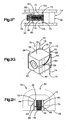
- the fixation assembly 22 includes a fixation housing 36 that is configured to be mounted or otherwise connected to the implant body 20.
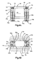
- the fixation housing 36 supports, either directly or indirectly, at least one bone or vertebral fixation member 38 and at least one actuator 40 that is configured to iterate the fixation assembly 22, and particular the at least one fixation member 38, between a retracted position illustrated in Fig. 2A and an extended position illustrated in Fig. 2B so as to fix the fixation assembly 22 and thus the implant 10 to the vertebral bodies 12a and 12b.
- the fixation housing 36 defines a front end 42 and a longitudinally opposed rear end 44, a top end 46 and a transversely opposed bottom end 48, and opposed lateral side 50 and 52.
- the top and bottom ends 46 and 48 can be configured to face the corresponding vertebral endplates 13a and 13b of the superior and inferior vertebral bodies 12a and 12b, respectively. In some embodiments, the top and bottom ends 46 and 48 can be configured to abut the corresponding vertebral endplates 13a and 13b.
- the front end 42 defines a proximal end of the fixation housing 36
- the rear end 44 defines a distal end of the fixation housing 36 that is spaced from the proximal end in the insertion direction along a central longitudinal axis 37.
- the fixation housing 36 and the implant body 20 include respective complementary engagement members 54 and 56 that can be configured as desired to mount or otherwise connect the fixation housing 36 to the implant body 20.
- the engagement member 54 of the fixation assembly 22 is configured as a transversely elongate rail 58 that projects laterally out from the sides 50 and 52 of the fixation housing 36.
- the rails 58 can terminate above the bottom end 48 of the fixation housing 36.
- the complementary engagement member 56 of the implant body 20 is configured as a pair of transversely elongate slots 60 sized to receive the rails 58.
- the slot 60 can terminate above the bottom end 30 of the implant body 20.
- the slots 60 are disposed on opposed sides of a pocket 62 that is defined by the implant body 20 and sized to receive the fixation housing 36.
- the fixation assembly 22 can be can be connected to the implant body 20 by inserting the fixation housing 36 into the pocket 62 of the implant body 20 such that the rails 58 are received in the slots 60.
- the fixation housing 36 can define a longitudinal length greater than the front end 24 of the implant body 20, such that the fixation housing 36 extends longitudinally into the central opening 25.
- the rails 58 and slots 60 can be sized such that the top and bottom ends 46 and 48 of the fixation housing 36 are substantially aligned or flush with the top and bottom ends 28 and 30 of the implant body 20.
- top and bottom ends 46 arid 48 of the fixation housing 36, and the top and bottom ends 28 and 30 of the implant body 20 can be configured to abut the vertebral endplates 13a and 13b:
- part or all of the top and bottom ends 28 and 30 of the implant body 20 and/or the top and bottom ends 46 and 48 of the fixation housing can be recessed with respect to the vertebral endplates 13a and 13b.
- top ends 28 and 46 and bottom ends 30 and 48 abut or are recessed from the respective vertebral endplates 13a and 13b, they can face a direction having a transverse directional component, such that it can be said that the top ends 28 and 46 and bottom ends 30 and 48 face the vertebral bodies 12a and 12b and thus define vertebral body facing surfaces.
- the engagement members 54 and 56 can be configured as desired to facilitation the connection of the fixation assembly 20 to the implant body 20.
- the fixation assembly 22 can be integral with the implant body 20.
- the fixation assembly 22 includes at least one aperture 63 defined by the fixation housing 36 that receives the actuator 40 and at least one channel that receives the at least one fixation member 38.
- the fixation housing 36 defines a first pair of laterally spaced superior channels 64 and a second pair of laterally spaced inferior channels 65 that can be vertically aligned with the superior channels 64.
- the channels 64 and 65 can extend in any direction as desired, and extend in a direction having both longitudinal and transverse directional components in accordance with the illustrated embodiment.
- the superior channels 64 extend longitudinally and transversely upwards so as to define a first proximal end that extends from the proximal end 42 of the fixation housing 36 to a second distal end that extends to the top end 46.
- the inferior channels 65 extend longitudinally and transversely down so as to define a first proximal end that extends from the proximal end 42 of the fixation housing 36 to the distal end that extends to the bottom end 48.
- the distal ends of the channels 64 and 65 are thus transversely and longitudinally displaced with respect to the respective proximal ends of the channels 64 and 65.
- the channels 64 and 65 extend laterally into the sides 50 and 52 of the fixation housing 36, though they can be alternatively positioned as desired.
- the fixation assembly 22 can include a pair of cover plates 66 that are attached to the sides 50 and 52 of the fixation housing 36 so as to laterally cover and laterally close the channels 64 and 65.
- the cover plates 66 can include the engagement rails 58 as described above.
- the fixation member 38 can be provided as a first staple 68 that defines a proximal end 77 and an opposed distal or terminal end 79 that, in turn, defines a corresponding tip 73 that is configured to be inserted into a corresponding vertebral body (e.g., through the endplate) so as to fix the fixation assembly 22 and thus the implant 10 to the vertebral body.
- the staple 68 includes a bass in the form of a crossbar 70 at the proximal end 77 and at least a first pair of laterally spaced pins 72 that extend out from the crossbar 70 at any location, such as at opposed outer ends of the crossbar 70 as illustrated.
- the implant 10 can include a second fixation member provided as a second staple 69 can further include a second pair of laterally spaced pins 74 that extend out from a second crossbar 71 at any location, such as at opposed outer ends of the crossbar 71 as illustrated.
- the pins 72 and 74 are attached to the respective crossbars 70 and 75 at their proximal ends, and define the tips 73 at their distal ends.
- the pins 72 and 74 can be entirely recessed in the fixation housing 36 such that the tips 73 do not extend out from the fixation housing 36.
- the tips 73 of the first and second pairs of pins 72 and 74 can extend into the vertebral bodies 12a and 12b when the fixation member 38 is in the extended position.
- the implant 10 can include a pair of fixation members that define respective pairs of pins 72 and 74, the first pair of pins 72 defining a tip 73 at its distal or terminal end that is configured to extend into the first vertebral body 12a in the extended position, and the second pair of pins 72 defining a tip that is configured to extend into the second vertebral body 12b in the extended position.
- the first pair of pins 72 extends superiorly and longitudinally distally from the crossbar 70 in the superior channels 64
- the second pair of pins 74 extends inferiorly and longitudinally distally from the crossbar 71 in the inferior channels 65.
- the channels 64 and 65 can curve along their length along a constant radius such that the pins 72 and 74 can be made from any suitable rigid material, or the channels 64 and 65 can define different curvatures along their length, such that the pins 72 and 74 can be made of any suitable flexible material.
- the pins 72 and 74 can be made from titanium or nitinol (nickel titanium).
- the pins 72 and 74 are movable within the channels 64 and 65 from the retracted position to the extended position whereby the distal ends of the pins 72 and 74 extend out from the fixation housing 36 and into the corresponding vertebral bodies 12a and 12b when the implant 10 is disposed in the intervertebral space 14.
- the distal ends of the pins 72 and 74 can extend out from the fixation housing 36 substantially in the transverse direction T.
- the actuator 40 is configured to iterate the fixation member 38 from the retracted position to the extended position.
- the actuator 40 can be provided as a screw 76 that defines external threads 78 along part or all of the length of a screw shaft 89 that engages corresponding internal threads 80 of the aperture 63. Accordingly, the screw 76 can translate distally in the aperture 63 and thus the fixation housing 36 as the screw 76 is rotated in the aperture 63 relative to the fixation housing 36.
- the screw 76 can translate along a direction that has a longitudinal directional component (e.g., distally) from a disengaged position to an engaged position.
- the fixation member 38 is in the retracted position.
- the screw 76 moves to the engaged position.
- the screw 76 defines a first engagement member illustrated as a groove 82 that can extend circumferentially or about an arc about the screw 76.
- the crossbars 70 and 71 define respective apertures, which can be cylindrical, that extends longitudinally through the crossbars 70 and 71, such that the crossbars 70 and 71 define a respective collars 84 and 85 that are sized to be inserted into the groove 82.
- the collars 84 and 85 can be circumferentially sized slightly greater than the groove 82 such that the screw 76 is rotatable with respect to the collars.
- the longitudinal dimension of the collars 84 and 85 can be substantially equal to that of the groove 82 such that the collars 84 and 85, and thus the staples 68 and 69, are substantially longitudinally fixed to the screw 76 such that the staples 68 and 69 translate as the screw 76 translates in the aperture 63.
- the pins 72 and 74 translate distally in the respective channels 64 and 65 to the extended position as the screw 76 translates, whereby the distal ends of the pins 72 and 74, and thus the tips 73, extend transversely out from the fixation housing 36 to a location transversely out from at least a portion of the implant body 20.
- the distal ends of the channels 64 and 65 can extend substantially transversely such that the portion of the pins 72 and 74 that extend out from the channels 64 and 65, including the tips 73, can be directed substantially in the transverse direction into the respective vertebral bodies 12a and 12b.
- the screw 76 defines an engagement member illustrated as a socket 86 that extends longitudinally into the proximal end of the screw 76.
- the socket 86 is illustrated as a hexagonal in shape, though it could be shaped as any suitable polygonal shape, including a "plus” shape, a “dash” shape, or any alternative shape as desired. Because the socket 86 extends longitudinally into the screw 76, the socket 86 defines a depth that is substantially parallel to the insertion direction of the implant 10 into the intervertebral space 14.
- an anterior approach into the intervertebral space 14 can facilitate both insertion of the implant 10 into the intervertebral space and movement of the actuator 40 from the disengaged position to the engaged position, thereby correspondingly causing the fixation member 38 to move from the retracted position to the extended position.
- an actuator tool such as a hex drive
- a hex drive can be inserted into the socket 86 and rotated, either manually or automatically so as to cause the screw 76 to rotate and translate distally relative to the fixation housing 36.
- the proximal end of the screw 76 extends longitudinally out to a location proximal of the front end 42 of the fixation housing 36 when the screw is in the disengaged position.
- the screw 76 translates distally to the engaged position, the screw 76 translates distally until the screw 76 reaches the engaged position.
- the aperture 63 can terminate at a location that prevents further translation of the screw 76 once the screw 76 has reached the engaged position.
- proximal end of the screw 76 is substantially flush with the front end 42 of the fixation housing when the screw 76 is in the engaged position.
- the fixation member 38 likewise translates distally, which causes the pins 72 and 74 to travel distally in their respective channels 64 and 65, thereby causing the tips 73 to initially protrude transversely from the upper and lower ends 46 and 48, respectively, of the fixation housing 36.
- the tips 73 extend increasingly out from the fixation housing 36 until the screw 76 is in the engaged position, at which point the tips 73 of the pins 72 and 74 are fully extended out from the fixation housing 36 and into the vertebral bodies 12a and 12b.
- the screw 76 can be rotated relative to the fixation housing 36 in a second opposite direction, thereby causing the screw 76 to translate proximally from the engaged position to the disengaged position. As the screw 76 translates proximally, the fixation member 38 likewise translates proximally, thereby causing the tips of the pins 72 and 74 to retract toward the respective channels 64 and 65.
- the tips 73 of the pins 72 and 74 can be recessed with respect to the vertebral bodies 12a and 12b, and fully retracted in the respective channels 64 and 65, at which point the implant 10 can be removed from the intervertebral space 14.
- the implant 10 can be constructed in accordance with any alternative embodiment as desired having at least one fixation member that is configured to move between a retracted position to an extended position as described above.
- fixation member that is configured to move between a retracted position to an extended position as described above.
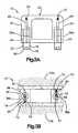
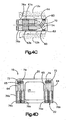
- the fixation assembly 22 of the implant 10 is illustrated in accordance with an alternative embodiment, whereby the fixation housing 36 includes a pair of laterally spaced fixation housing segments 36a and 36b that are connected to the lateral sides 32 and 34 of the implant body 20.
- Each housing segment 36a and 36b defines an aperture 63 that receives an actuator 40 illustrated as a screw 76 in the manner described above.
- the superior channel 64 extends centrally from one of the apertures 63 in the housing segment 36b, and the inferior channel 65 extends centrally from the other aperture 63 in the housing segment 36a.
- Each of the screws 76 can define a bore 81 that extends centrally into their distal ends, such that the proximal ends of at least a first fixation member illustrated as a first pin 72 extends into the central bore 81 of the screw 76 disposed in the housing segment 36a. The first pin 72 further extends into the superior channel 64. The proximal ends of at least a second fixation member illustrated as a pin 74 extends into the central bore 81 of the screw 76 disposed in the housing segment 36b, such that the second pin further extends into the inferior channel 64.
- a first fixation member illustrated as a first pin 72 extends into the central bore 81 of the screw 76 disposed in the housing segment 36a.
- the first pin 72 further extends into the superior channel 64.
- the proximal ends of at least a second fixation member illustrated as a pin 74 extends into the central bore 81 of the screw 76 disposed in the housing segment 36b, such that the second pin further extends into the inferior channel 64.
- the proximal ends of the pins 72 and 74 are rotatably coupled to the respective screws inside the bore 81, and can be attached to the screws 76 via adhesive or weldments, or can alternatively be integrally connected to the screws 76.
- the pins 72 and 74 are coupled to the respective screws 76 with respect to both translation and rotation, such that the pins 72 and 74 both rotate and translate along with the respective screws 76 to which they are connected.
- the pins 72 and 74 extend into the respective channels 64 and 65, which extend superiorly and inferiorly, respectively, and longitudinally distally as described above.
- the screws 76 translate as they rotate in the housing 36 in the manner described above, which causes the pins 72 and 74 to rotate as they travel distally in the respective channels 64 and 65.
- the tips 73 therefore also rotate as they translate out from the fixation housing 36.
- the pins 72 and 74 can each include a cutting bit, for instance cutting flutes 83, at their tips 73 so as to facilitate cutting into the vertebral bodies 12a and 12b as the pins 72 rotate and translate from their retracted positions to their extended positions.
- the screws 76, channels 64 and 65, and pins 72 and 74 can extend substantially parallel to each other (longitudinally as illustrated in Figs. 3A-F ), or can be angularly offset with respect to each other.
- the screws 76 and the channels 64 and 65, and thus the pins 72 and 74 can converge toward each other along a direction from their proximal ends to their distal ends as illustrated in Fig. 3G .
- the channels 64 and 65 can diverge away from each other along a direction from their proximal ends to their distal ends.
- the implant 10 can include a pair of screws 76 at each lateral side 32 and 34.
- each side 32 and 34 can include a superior screw 76 coupled to a superior pin in the manner described above, and an inferior screw 76 located inferior with respect to the superior screw and coupled to an inferior pin in the manner described above, such that each lateral side of the implant body 20 can be fixed to both the superior vertebral body 12a and the inferior vertebral body 12b.
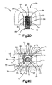
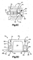
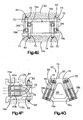
- the fixation assembly 22 of the implant 10 is illustrated in accordance with an alternative embodiment, whereby the laterally spaced fixation housing segments 36a and 36b each include a superior aperture 63a and an inferior aperture 63b that each receive an actuator 40 illustrated as a superior screw 76a and an inferior screw 76b in the manner described above.
- the superior aperture 63a and the inferior aperture 63b can be laterally displaced from each other by a distance at least equal to the thickness of the channels 64 and 65.
- the superior channel 64 can extend from the inferior aperture 63b and the inferior channel 65 can extend from the superior aperture 63a, such that the channels 64 and 65 in each housing segment 36a and 36b cross over each other and can be longitudinally and transversely aligned without interfering with each other.
- the superior channels 64 extend centrally from the inferior apertures 63 in the housing segments 36a and 36b, and the inferior channels 65 extend centrally from the apertures 63 in the housing segments 36a and 36b.
- Each of the screws 76a and 76b can define a bore 81 that extends centrally into their distal ends.
- the proximal ends of at least a first fixation member 38 such as a pair of first fixation members illustrated as a pair of first pins 72 extends into the central bore 81 of the corresponding pair of the inferior screws 76b that are disposed in the inferior apertures 63b and aligned with the superior channels 64.
- the first pins 72 further extend into the superior channels 64 from the inferior screws 76b.
- a second fixation member such as a pair of second fixation members illustrated as a pair of second pins 74 extends into the central bore 81 of the corresponding pair of superior screws 76a that are disposed in the superior apertures 63a and aligned with the inferior channels 65.
- the second pins 74 further extend into the inferior channels 65 from the superior screws 76a.
- the proximal ends of the pins 72 and 74 are rotatably coupled to the respective screws 76a and 76b inside the bore 81, and can be attached to the screws 76a and 76b via adhesive or weldments, or can alternatively be integrally connected to the screws 76a and 76b.
- the pins 72 and 74 are coupled to the respective screws 76b and 76a with respect to both translation and rotation, such that the pins 72 and 74 rotate and translate with the respective screws 76b and 76a to which they are connected.
- the pins 72 extend into the superior channels 64 from the inferior screws 76b, and the pins 74 extend into the inferior channels 65 from the superior screws 76a.
- Both channels 64 and 65 extend from the respective apertures 63b and 63a in a direction having both longitudinal and transverse directional components.
- the proximal ends of the superior channels 64 are inferior with respect to the proximal ends of the inferior channels 65, and the distal ends of the superior channels 64 are superior with respect to the superior ends of the inferior channels 65.
- the distal ends of the superior channels 64 extend through the top end of the fixation housing 36 and/or implant body 20.
- the distal ends of the inferior channels 64 extend through the bottom end of the fixation housing 36 and/or implant body 20.
- the screws 76 translate as they rotate in the housing 36 in the manner described above, which causes the pins 72 and 74 to rotate as they travel distally in the respective channels 64 and 65.
- the tips 73 therefore also rotate as they translate out from the fixation housing 36.
- the pins 72 and 74 can each include a cutting bit, for instance cutting flutes 83, at their tips 73 so as to facilitate cutting into the vertebral bodies 12a and 12b as the pins 72 rotate and translate from their retracted positions to their extended positions.
- the pins 72 that are connected to the inferior screws 76b extend through the superior channels 64 such that the tips 73 extend transversely outward with respect to the fixation housing 36 and /or the implant body 20 along a direction having a transverse directional component into the superior vertebral body 12a when the implant 10 is disposed in the intervertebral space 14 and the pins 72 have been iterated to their extended position.
- the pins 74 that are connected to the superior screws 76a extend through the inferior channels 65 such that the tips 73 extend transversely outward with respect to the fixation housing 36 and/or the implant body 20 along a direction having a transverse directional component into the inferior vertebral body 12b when the implant 10 is disposed in the intervertebral space 14 and the pins 74 have been iterated to their extended position.
- the channels 64 and 65 can extend substantially parallel to each other (longitudinally as illustrated in Figs. 4A-F ), or can be angularly offset with respect to each other. For instance, the channels 64 and 65 can converge toward each other along a direction from their proximal ends to their distal ends as illustrated in Fig. 4G . Alternatively still, the channels 64 and 65 can diverge away from each other along a direction from their proximal ends to their distal ends.
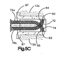
- the fixation assembly 22 of the implant 10 is illustrated substantially as described with respect to Figs. 4A-G , however the pins 72 and 74 can include external threads 87 along part or all of their length, for instance at the terminal end that extends transversely out from the fixation housing 36. Accordingly, as the pins 72 and 74 rotate to their extended position, the threads 87 engage the vertebral bodies 12a and 12b. The threads 87 can have a pitch that is the same or different than the pitch of the external threads 78 of the corresponding screws 76. Furthermore, the pins 72 and 74 are illustrated as integral with the screws 76a and 76b.
- the term “or” is used in its nonexclusive form (e.g. "A or B” includes A; B, A and B, or any combination thereof; but does not have to include all of these possibilities). It should be noted that, unless otherwise specified, “and/or” is used similarly (e.g. “A and/or B” includes A, B, A and B, or any combination thereof, but does not have to include all of these possibilities). It should be noted that, unless otherwise specified, the term “includes” means “comprises” (e.g. a device that includes or comprises A and B contains A and B but optionally may contain C or additional components other than A and B). It should be noted that, unless otherwise specified, the singular forms "a,” “an,” and “the” refer to one or more than one, unless the context clearly dictates otherwise.
- the words which have been used herein are words of description and illustration, rather than words of limitation.
- the implant can alternatively be inserted into a space between any bones or bone segments (e.g., fractured bone segments) as desired, and subsequently fixed to the adjacent bones or bone segments in the manner described herein.
- the invention has been described herein with reference to particular structure, methods, and embodiments, the invention is not intended to be limited to the particulars disclosed herein, as the invention extends to all structures, methods and uses that are within the scope of the present invention.
Description
- The human vertebral column (also known as the backbone or spine) houses the spinal cord in its spinal canal. The vertebral column is made up of a plurality of vertebrae. A typical vertebra includes two primary parts, including an anterior portion that includes the vertebral body, and a posterior portion that encloses the foramen. Each vertebral body defines superior and inferior vertebral endplates that, such that adjacent vertebrae define an intervertebral space that includes disc material between the respective endplates.
- Historically, spinal abnormalities have indicated complete removal of a disc from the intervertebral space followed by fusion the adjacent vertebrae together. This "spinal fusion" procedure, which is still in use today, is a widely accepted surgical treatment for symptomatic lumbar and cervical degenerative disc disease. Early fusion procedures used an implant made of bone from a patient's hip or a cadaver bone as a spacer in the intervertebral space so as to properly position the adjacent vertebrae until the vertebrae were fused together. More modem procedures use implants made from a material having a relatively low modulus of elasticity to encourage bone growth. For instance, the implant can contain some of the patient's own bone, e.g., within apertures of the implant. Conventional implants can be made from desired material, including radiolucent materials such as polyetheretherketone (PEEK), ultra-high molecular weight polyethylenes (UHMWPE) or polysulfones (PSU). It can be desirable for the material to have a modulus of elasticity between 3 and 5 GPa.
- Conventional intervertebral implant designs have attempted to achieve implant fixation in the intervertebral space.
-
EP 2 047 825 A1 discloses an intervertebral implant configured to be fixed in an intervertebral space. The implant has a weight-bearing shell including a key-way opening. A plurality of anchors is rotatably disposed in the weight-bearing shell. A key can be inserted into the weight-bearing shell to rotate the plurality of anchors in planes perpendicular to an anterior-posterior direction from a retracted position to an extended position where the plurality of anchors extend out from the weight-bearing shell into the adjacent vertebral bodies. - In accordance with one embodiment, an intervertebral implant is configured to be fixed in an intervertebral space defined by a first vertebral body and a second vertebral body. The intervertebral implant includes an implant body sized to be inserted into an intervertebral space, and a fixation assembly configured to be attached to the implant body. The fixation assembly includes the features recited in claim 1.
- The foregoing summary, as well as the following detailed description of example embodiments of the present disclosure, will be better understood when read in conjunction with the appended drawings. For the purposes of illustrating the example embodiments of the present disclosure, references to the drawings are made. It should be understood, however, that the application is not limited to the precise arrangements and instrumentalities shown. In the drawings:
-
Fig. 1A is a perspective view of a pair of vertebral bodies separated by an intervertebral space; -
Fig. 1B is a perspective view of the vertebral bodies illustrated inFig. 1 , and an intervertebral implant inserted into the intervertebral space between the two vertebral bodies; -
Fig. 2A is a perspective view of an intervertebral implant including an implant body and a fixation assembly connected to the intervertebral implant, showing the fixation assembly in accordance with one embodiment in a retracted position; -
Fig. 2B is a perspective view of the intervertebral implant as illustrated inFig. 2A , showing the fixation assembly in an extended position; -
Fig. 2C is an exploded assembly view of the intervertebral implant illustrated inFig. 2A , showing the connection of the fixation assembly to the implant body; -
Fig. 2D is a top plan view of the intervertebral implant illustrated inFig. 2A having portions removed for the purposes of clarity; -
Fig. 2E is a front elevation view of the intervertebral implant as illustrated inFig. 2A , having portions removed for the purposes of clarity, shown in an intervertebral space; -
Fig. 2F is a side view of the intervertebral implant as illustrated inFig. 2E , having portions removed for the purposes of clarity; -
Fig. 2G is a perspective view of the fixation assembly as illustrated inFig. 2B ; -
Fig. 2H is a top plan view of the intervertebral implant as illustrated inFig. 2B , having portions removed for the purposes of clarity; -
Fig. 2I is a front elevation view of the intervertebral implant as illustrated inFig. 2B , having portions removed for the purposes of clarity, shown in an intervertebral space; -
Fig. 2J is a side view of the intervertebral implant as illustrated inFig. 2I , having portions removed for the purposes of clarity; -
Fig. 3A is a top plan view of an intervertebral implant including an implant body and a fixation assembly constructed in accordance with an alternative embodiment, having portions removed for the purposes of clarity, showing the fixation assembly in a retracted position; -
Fig. 3B is a front elevation view of the intervertebral implant as illustrated inFig. 3A , having portions removed for the purposes of clarity, shown in an intervertebral space; -
Fig. 3C is a side elevation view of the intervertebral implant as illustrated inFig. 3B , having portions removed for the purposes of clarity; -
Fig. 3D is a top plan view of the intervertebral implant illustrated inFig. 3A , but showing the fixation assembly in an extended position; -
Fig. 3E is a front elevation view of the intervertebral implant as illustrated inFig. 3D , having portions removed for the purposes of clarity, shown in an intervertebral space; -
Fig. 3F is a side elevation view of the intervertebral implant as illustrated inFig. 3D , having portions removed for the purposes of clarity; -
Fig. 3G is a top plan view of an intervertebral implant similar to the intervertebral implant as illustrated inFig. 3D , but constructed in accordance with an alternative embodiment; -
Fig. 4A is a top plan view of an intervertebral implant including an implant body and a fixation assembly constructed in accordance with an alternative embodiment, having portions removed for the purposes of clarity, showing the fixation assembly in a retracted position; -
Fig. 4B is a front elevation view of the intervertebral implant as illustrated inFig. 4A , having portions removed for the purposes of clarity, shown in an intervertebral space; -
Fig. 4C is a side elevation view of the intervertebral implant as illustrated inFig. 4B , having portions removed for the purposes of clarity; -
Fig. 4D is a top plan view of the intervertebral implant illustrated inFig. 4A , but showing the fixation assembly in an extended position; -
Fig. 4E is a front elevation view of the intervertebral implant as illustrated inFig. 4D , having portions removed for the purposes of clarity, shown in an intervertebral space; -
Fig. 4F is a side elevation view of the intervertebral implant as illustrated inFig. 4D , having portions removed for the purposes of clarity; -
Fig. 4G is a top plan view of an intervertebral implant similar to the intervertebral implant as illustrated inFig. 4D , but constructed in accordance with an alternative embodiment; -
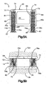
Fig. 5A is a top plan view of an intervertebral implant including an implant body and a fixation assembly constructed in accordance with an alternative embodiment, having portions removed for the purposes of clarity, showing the fixation assembly in a retracted position; -
Fig. 5B is a front elevation view of the intervertebral implant as illustrated inFig. 5A , having portions removed for the purposes of clarity, shown in an intervertebral space; -
Fig. 5C is a side elevation view of the intervertebral implant as illustrated inFig. 5B , having portions removed for the purposes of clarity; -
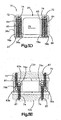
Fig. 5D is a top plan view of the intervertebral implant illustrated inFig. 5A , but showing the fixation assembly in an extended position; -
Fig. 5E is a front elevation view of the intervertebral implant as illustrated inFig. 5D , having portions removed for the purposes of clarity, shown in an intervertebral space; -
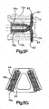
Fig. 5F is a side elevation view of the intervertebral implant as illustrated inFig. 5D , having portions removed for the purposes of clarity; -
Fig. 5G is a top plan view of an intervertebral implant similar to the intervertebral implant as illustrated inFig. 5D , but constructed in accordance with an alternative embodiment; - Referring to
Figs. 1A-B , a first superiorvertebral body 12a defines a superiorvertebral endplate 13a of anintervertebral space 14, and an adjacent second inferiorvertebral body 12b defines an inferiorvertebral endplate 13b of theintervertebral space 14. Thus, theintervertebral space 14 is disposed between thevertebral bodies 12a-b. Thevertebral bodies 12a-b can be anatomically adjacent vertebral bodies, or can remain after a discectomy has been performed that removed a vertebral body from a location between thevertebral bodies 12a-b. As illustrated, theintervertebral space 14 is illustrated after a discectomy, whereby the disc material has been removed to prepare theintervertebral space 14 to receive an orthopedic implant, such as theintervertebral implant 10 illustrated inFig. 2 . Thus, theimplant 10 is configured to be inserted into theintervertebral space 14, and achieve restoration of height while maintaining mobility. Theintervertebral space 14 can be disposed anywhere along the spine as desired. As will be appreciated from the description below, theimplant 10 can be sized as desired so as to be implantable in an intervertebral disc space in any region of the spine, including the lumbar region, thoracic region, cervical region, sacral region, and coccygeal region. - Certain terminology is used in the following description for convenience only and is not limiting. The words "right", "left", "lower" and "upper" designate directions in the drawings to which reference is made. The words "inner" or "distal" and "outer" or "proximal" refer to directions toward and away from, respectively, the geometric center of the implant and related parts thereof. The words, "anterior", "posterior," "superior," "inferior," "medial," "lateral," and related words and/or phrases designate preferred positions and orientations in the human body to which reference is made and are not meant to be limiting. The terminology includes the above-listed words, derivatives thereof and words of similar import.
- The
implant 10 and various components of theimplant 10 are described herein extending horizontally along a longitudinal direction L and a lateral direction A, and vertically along a transverse direction T. Unless otherwise specified herein, the terms "lateral," "longitudinal," and "transverse" are used to describe the orthogonal directional components of various components. The lateral direction A and longitudinal direction L are angularly offset, for instance substantially orthogonal, with respect to each other and with respect to the transverse direction T. It should be appreciated that while the longitudinal and lateral directions are illustrated as extending along a horizontal plane, and that the transverse direction is illustrated as extending along a vertical plane, the planes that encompass the various directions may differ during use. For instance, when theimplant 10 is implanted into an intervertebral space, such as theintervertebral space 14, the transverse direction T extends generally along the superior-inferior (or cranial- caudal) direction, while the plane defined by the longitudinal direction L and lateral direction A lie generally in the anatomical plane defined by the anterior-posterior direction, and the medial-lateral direction, respectively. Accordingly, the directional terms "vertical" and "horizontal" are used to describe theimplant 10 and its components as illustrated merely for the purposes of clarity and illustration. - Referring now to
Figs. 2A-C , theintervertebral implant 10 includes animplant body 20 and afixation assembly 22 configured to secure theimplant body 20 to the first and secondvertebral bodies intervertebral space 14. Theimplant 10 and components thereof can be formed from any of a variety of biocompatible materials, such as cobalt chromium molybdenum (CoCrMo), titanium and titanium alloys, stainless steel, ceramics, or polymers such as polyetheretherketone (PEEK), ultra-high molecular weight polyethylenes (UHMWPE) or polysulfones (PSU), bioresorbable materials, and bonegraft (for example allograft and xenograft). A coating may be added or applied to theimplant 10 to improve physical or chemical properties. The coatings may help to ensure bony in or on growth or medication. Examples of coatings include plasma-sprayed titanium coating or hydroxyapatite. - The
implant body 20 defines afront end 24 and a longitudinally opposedrear end 26, atop end 28 and a transversely opposedbottom end 30, and opposedlateral sides vertebral endplates vertebral bodies vertebral endplates implant 10 can be inserted into theintervertebral space 14 along an insertion direction which can be an anterior-posterior approach (for instance when thevertebral bodies longitudinal end 24 is anterior to the rearlongitudinal end 26. - The implant body can be sized and shaped as desired, and is illustrated as substantially "D" shaped, such that the
front end 24 extends substantially straight in the lateral direction A, and the lateral sides 32 and 34 curve toward each other in a rearward direction to therear end 26. In accordance with the illustrated embodiment, theimplant body 20 defines a substantially central "D" shapedcentral opening 25 that extends transversely into (through as illustrated) theimplant body 20. Thecentral opening 25 can receive any suitable bone growth promoting material, such as allograft and xenograft to promote bone growth with thevertebral bodies 12a-b after implantation of theimplant 10 into theintervertebral space 14. Theimplant body 20 can be solid as illustrated, or can define perforations that extend into or through theimplant body 20 that can, for instance, receive the bone growth promoting material. - The
implant body 20 defines a transverse height H between the top and bottom ends 28 and 30. The height H can be substantially constant from thefront end 24 to therear end 26, or can be variable from thefront end 24 to therear end 26 so as to impart or restore a lordotic curvature to thevertebral bodies front end 24 toward therear end 26, or can increase in the rearward direction. Furthermore, the height H can be constant or variable between thelateral sides vertebral endplates implants 10 can also be provided, each having a plurality ofimplant bodies 20 of different shapes or sizes. For instance, the kit can include a plurality ofimplant bodies 20 of different heights H, such that at least one of theimplant bodies 20 in the kit can correspond with the corresponding different height of intervertebral spaces along the vertebral column of a given patient, or of an intervertebral space of different patients. - The
fixation assembly 22 includes afixation housing 36 that is configured to be mounted or otherwise connected to theimplant body 20. Thefixation housing 36 supports, either directly or indirectly, at least one bone orvertebral fixation member 38 and at least oneactuator 40 that is configured to iterate thefixation assembly 22, and particular the at least onefixation member 38, between a retracted position illustrated inFig. 2A and an extended position illustrated inFig. 2B so as to fix thefixation assembly 22 and thus theimplant 10 to thevertebral bodies fixation housing 36 defines afront end 42 and a longitudinally opposedrear end 44, atop end 46 and a transversely opposedbottom end 48, and opposedlateral side vertebral endplates vertebral bodies vertebral endplates front end 42 defines a proximal end of thefixation housing 36, and therear end 44 defines a distal end of thefixation housing 36 that is spaced from the proximal end in the insertion direction along a centrallongitudinal axis 37. - The
fixation housing 36 and theimplant body 20 include respectivecomplementary engagement members fixation housing 36 to theimplant body 20. In accordance with the illustrated embodiment, theengagement member 54 of thefixation assembly 22 is configured as a transverselyelongate rail 58 that projects laterally out from thesides fixation housing 36. Therails 58 can terminate above thebottom end 48 of thefixation housing 36. In accordance with the illustrated embodiment, thecomplementary engagement member 56 of theimplant body 20 is configured as a pair of transverselyelongate slots 60 sized to receive therails 58. Theslot 60 can terminate above thebottom end 30 of theimplant body 20. Theslots 60 are disposed on opposed sides of apocket 62 that is defined by theimplant body 20 and sized to receive thefixation housing 36. - Accordingly, the
fixation assembly 22 can be can be connected to theimplant body 20 by inserting thefixation housing 36 into thepocket 62 of theimplant body 20 such that therails 58 are received in theslots 60. Thefixation housing 36 can define a longitudinal length greater than thefront end 24 of theimplant body 20, such that thefixation housing 36 extends longitudinally into thecentral opening 25. Therails 58 andslots 60 can be sized such that the top and bottom ends 46 and 48 of thefixation housing 36 are substantially aligned or flush with the top and bottom ends 28 and 30 of theimplant body 20. Accordingly, the top and bottom ends 46 arid 48 of thefixation housing 36, and the top and bottom ends 28 and 30 of theimplant body 20, can be configured to abut thevertebral endplates implant body 20 and/or the top and bottom ends 46 and 48 of the fixation housing can be recessed with respect to thevertebral endplates vertebral endplates vertebral bodies engagement members fixation assembly 20 to theimplant body 20. For instance, thefixation assembly 22 can be integral with theimplant body 20. - Referring also to
Figs. 2D-F , thefixation assembly 22 includes at least oneaperture 63 defined by thefixation housing 36 that receives theactuator 40 and at least one channel that receives the at least onefixation member 38. In accordance with the illustrated embodiment, thefixation housing 36 defines a first pair of laterally spacedsuperior channels 64 and a second pair of laterally spacedinferior channels 65 that can be vertically aligned with thesuperior channels 64. Thechannels superior channels 64 extend longitudinally and transversely upwards so as to define a first proximal end that extends from theproximal end 42 of thefixation housing 36 to a second distal end that extends to thetop end 46. Theinferior channels 65 extend longitudinally and transversely down so as to define a first proximal end that extends from theproximal end 42 of thefixation housing 36 to the distal end that extends to thebottom end 48. The distal ends of thechannels channels - In accordance with the illustrated embodiment, the
channels sides fixation housing 36, though they can be alternatively positioned as desired. Thefixation assembly 22 can include a pair ofcover plates 66 that are attached to thesides fixation housing 36 so as to laterally cover and laterally close thechannels cover plates 66 can include the engagement rails 58 as described above. - The
fixation member 38 can be provided as afirst staple 68 that defines aproximal end 77 and an opposed distal orterminal end 79 that, in turn, defines acorresponding tip 73 that is configured to be inserted into a corresponding vertebral body (e.g., through the endplate) so as to fix thefixation assembly 22 and thus theimplant 10 to the vertebral body. The staple 68 includes a bass in the form of acrossbar 70 at theproximal end 77 and at least a first pair of laterally spacedpins 72 that extend out from thecrossbar 70 at any location, such as at opposed outer ends of thecrossbar 70 as illustrated. Theimplant 10 can include a second fixation member provided as asecond staple 69 can further include a second pair of laterally spacedpins 74 that extend out from asecond crossbar 71 at any location, such as at opposed outer ends of thecrossbar 71 as illustrated. - The
pins respective crossbars 70 and 75 at their proximal ends, and define thetips 73 at their distal ends. When thestaples pins fixation housing 36 such that thetips 73 do not extend out from thefixation housing 36. Thetips 73 of the first and second pairs ofpins vertebral bodies fixation member 38 is in the extended position. Thus theimplant 10 can include a pair of fixation members that define respective pairs ofpins pins 72 defining atip 73 at its distal or terminal end that is configured to extend into the firstvertebral body 12a in the extended position, and the second pair ofpins 72 defining a tip that is configured to extend into the secondvertebral body 12b in the extended position. - In accordance with the illustrated embodiment, the first pair of
pins 72 extends superiorly and longitudinally distally from thecrossbar 70 in thesuperior channels 64, and the second pair ofpins 74 extends inferiorly and longitudinally distally from thecrossbar 71 in theinferior channels 65. It should be appreciated, however, that the first and second pairs ofpins channels pins channels pins pins pins channels pins fixation housing 36 and into the correspondingvertebral bodies implant 10 is disposed in theintervertebral space 14. The distal ends of thepins fixation housing 36 substantially in the transverse direction T. - With continuing reference to
Figs. 2A-F , theactuator 40 is configured to iterate thefixation member 38 from the retracted position to the extended position. In accordance with the illustrated embodiment, theactuator 40 can be provided as ascrew 76 that definesexternal threads 78 along part or all of the length of a screw shaft 89 that engages correspondinginternal threads 80 of theaperture 63. Accordingly, thescrew 76 can translate distally in theaperture 63 and thus thefixation housing 36 as thescrew 76 is rotated in theaperture 63 relative to thefixation housing 36. During operation, thescrew 76 can translate along a direction that has a longitudinal directional component (e.g., distally) from a disengaged position to an engaged position. When thescrew 76 is in the disengaged position, thefixation member 38 is in the retracted position. When thescrew 76 moves to the engaged position, thescrew 76 moves thefixation member 38 to the extended position. - Referring also to
Figs. 2G-J , thescrew 76 defines a first engagement member illustrated as agroove 82 that can extend circumferentially or about an arc about thescrew 76. Thecrossbars crossbars crossbars respective collars groove 82. Thecollars groove 82 such that thescrew 76 is rotatable with respect to the collars. The longitudinal dimension of thecollars groove 82 such that thecollars staples screw 76 such that thestaples screw 76 translates in theaperture 63. Thus, thepins respective channels screw 76 translates, whereby the distal ends of thepins tips 73, extend transversely out from thefixation housing 36 to a location transversely out from at least a portion of theimplant body 20. The distal ends of thechannels pins channels tips 73, can be directed substantially in the transverse direction into the respectivevertebral bodies - The
screw 76 defines an engagement member illustrated as asocket 86 that extends longitudinally into the proximal end of thescrew 76. Thesocket 86 is illustrated as a hexagonal in shape, though it could be shaped as any suitable polygonal shape, including a "plus" shape, a "dash" shape, or any alternative shape as desired. Because thesocket 86 extends longitudinally into thescrew 76, thesocket 86 defines a depth that is substantially parallel to the insertion direction of theimplant 10 into theintervertebral space 14. Accordingly, an anterior approach into theintervertebral space 14 can facilitate both insertion of theimplant 10 into the intervertebral space and movement of the actuator 40 from the disengaged position to the engaged position, thereby correspondingly causing thefixation member 38 to move from the retracted position to the extended position. - Thus, an actuator tool, such as a hex drive, can be inserted into the
socket 86 and rotated, either manually or automatically so as to cause thescrew 76 to rotate and translate distally relative to thefixation housing 36. In accordance with the illustrated embodiment, the proximal end of thescrew 76 extends longitudinally out to a location proximal of thefront end 42 of thefixation housing 36 when the screw is in the disengaged position. As thescrew 76 translates distally to the engaged position, thescrew 76 translates distally until thescrew 76 reaches the engaged position. For instance, theaperture 63 can terminate at a location that prevents further translation of thescrew 76 once thescrew 76 has reached the engaged position. In accordance with the illustrated embodiment, proximal end of thescrew 76 is substantially flush with thefront end 42 of the fixation housing when thescrew 76 is in the engaged position. As thescrew 76 translates distally, thefixation member 38 likewise translates distally, which causes thepins respective channels tips 73 to initially protrude transversely from the upper and lower ends 46 and 48, respectively, of thefixation housing 36. As thescrew 76 and pins 72 and 74 continue to translate distally, thetips 73 extend increasingly out from thefixation housing 36 until thescrew 76 is in the engaged position, at which point thetips 73 of thepins fixation housing 36 and into thevertebral bodies - If it is desired to retract the
pins implant 10 from theintervertebral space 14, thescrew 76 can be rotated relative to thefixation housing 36 in a second opposite direction, thereby causing thescrew 76 to translate proximally from the engaged position to the disengaged position. As thescrew 76 translates proximally, thefixation member 38 likewise translates proximally, thereby causing the tips of thepins respective channels screw 76 has been fully retracted such that the screw is in the disengaged position, thetips 73 of thepins vertebral bodies respective channels implant 10 can be removed from theintervertebral space 14. - While the implant has been described in accordance with one embodiment, it should be appreciated that the
implant 10 can be constructed in accordance with any alternative embodiment as desired having at least one fixation member that is configured to move between a retracted position to an extended position as described above. A number of such alternative embodiments are described below, it being appreciated that the embodiments are described herein for the purposes of illustration, and that other alternative embodiments are contemplated beyond those explicitly described herein, for instance as defined by the appended claims. - For instance, referring to
Figs. 3A-C , thefixation assembly 22 of theimplant 10 is illustrated in accordance with an alternative embodiment, whereby thefixation housing 36 includes a pair of laterally spacedfixation housing segments implant body 20. Eachhousing segment aperture 63 that receives anactuator 40 illustrated as ascrew 76 in the manner described above. Thesuperior channel 64 extends centrally from one of theapertures 63 in thehousing segment 36b, and theinferior channel 65 extends centrally from theother aperture 63 in thehousing segment 36a. Each of thescrews 76 can define abore 81 that extends centrally into their distal ends, such that the proximal ends of at least a first fixation member illustrated as afirst pin 72 extends into thecentral bore 81 of thescrew 76 disposed in thehousing segment 36a. Thefirst pin 72 further extends into thesuperior channel 64. The proximal ends of at least a second fixation member illustrated as apin 74 extends into thecentral bore 81 of thescrew 76 disposed in thehousing segment 36b, such that the second pin further extends into theinferior channel 64. - Referring also to
Figs. 3D-F , the proximal ends of thepins bore 81, and can be attached to thescrews 76 via adhesive or weldments, or can alternatively be integrally connected to thescrews 76. Thus, thepins respective screws 76 with respect to both translation and rotation, such that thepins respective screws 76 to which they are connected. Thepins respective channels screws 76 translate as they rotate in thehousing 36 in the manner described above, which causes thepins respective channels tips 73 therefore also rotate as they translate out from thefixation housing 36. Thepins instance cutting flutes 83, at theirtips 73 so as to facilitate cutting into thevertebral bodies pins 72 rotate and translate from their retracted positions to their extended positions. - The
screws 76,channels Figs. 3A-F ), or can be angularly offset with respect to each other. For instance, thescrews 76 and thechannels pins Fig. 3G . Alternatively still, thechannels - Alternatively still, the
implant 10 can include a pair ofscrews 76 at eachlateral side side superior screw 76 coupled to a superior pin in the manner described above, and aninferior screw 76 located inferior with respect to the superior screw and coupled to an inferior pin in the manner described above, such that each lateral side of theimplant body 20 can be fixed to both the superiorvertebral body 12a and the inferiorvertebral body 12b. - Referring now to
Figs. 4A-C , thefixation assembly 22 of theimplant 10 is illustrated in accordance with an alternative embodiment, whereby the laterally spacedfixation housing segments superior aperture 63a and aninferior aperture 63b that each receive anactuator 40 illustrated as asuperior screw 76a and aninferior screw 76b in the manner described above. Thesuperior aperture 63a and theinferior aperture 63b can be laterally displaced from each other by a distance at least equal to the thickness of thechannels superior channel 64 can extend from theinferior aperture 63b and theinferior channel 65 can extend from thesuperior aperture 63a, such that thechannels housing segment - The
superior channels 64 extend centrally from theinferior apertures 63 in thehousing segments inferior channels 65 extend centrally from theapertures 63 in thehousing segments screws bore 81 that extends centrally into their distal ends. The proximal ends of at least afirst fixation member 38 such as a pair of first fixation members illustrated as a pair offirst pins 72 extends into thecentral bore 81 of the corresponding pair of theinferior screws 76b that are disposed in theinferior apertures 63b and aligned with thesuperior channels 64. The first pins 72 further extend into thesuperior channels 64 from theinferior screws 76b. The proximal ends of at least a second fixation member such as a pair of second fixation members illustrated as a pair ofsecond pins 74 extends into thecentral bore 81 of the corresponding pair ofsuperior screws 76a that are disposed in thesuperior apertures 63a and aligned with theinferior channels 65. The second pins 74 further extend into theinferior channels 65 from thesuperior screws 76a. - Referring also to
Figs. 4D-F , the proximal ends of thepins respective screws bore 81, and can be attached to thescrews screws pins respective screws pins respective screws pins 72 extend into thesuperior channels 64 from theinferior screws 76b, and thepins 74 extend into theinferior channels 65 from thesuperior screws 76a. - Both
channels respective apertures superior channels 64 are inferior with respect to the proximal ends of theinferior channels 65, and the distal ends of thesuperior channels 64 are superior with respect to the superior ends of theinferior channels 65. For instance, the distal ends of thesuperior channels 64 extend through the top end of thefixation housing 36 and/orimplant body 20. The distal ends of theinferior channels 64 extend through the bottom end of thefixation housing 36 and/orimplant body 20. During operation, thescrews 76 translate as they rotate in thehousing 36 in the manner described above, which causes thepins respective channels tips 73 therefore also rotate as they translate out from thefixation housing 36. Thepins instance cutting flutes 83, at theirtips 73 so as to facilitate cutting into thevertebral bodies pins 72 rotate and translate from their retracted positions to their extended positions. Thepins 72 that are connected to theinferior screws 76b extend through thesuperior channels 64 such that thetips 73 extend transversely outward with respect to thefixation housing 36 and /or theimplant body 20 along a direction having a transverse directional component into the superiorvertebral body 12a when theimplant 10 is disposed in theintervertebral space 14 and thepins 72 have been iterated to their extended position. Thepins 74 that are connected to thesuperior screws 76a extend through theinferior channels 65 such that thetips 73 extend transversely outward with respect to thefixation housing 36 and/or theimplant body 20 along a direction having a transverse directional component into the inferiorvertebral body 12b when theimplant 10 is disposed in theintervertebral space 14 and thepins 74 have been iterated to their extended position. - The
channels Figs. 4A-F ), or can be angularly offset with respect to each other. For instance, thechannels Fig. 4G . Alternatively still, thechannels - Referring now to
Figs. 5A-G , thefixation assembly 22 of theimplant 10 is illustrated substantially as described with respect toFigs. 4A-G , however thepins external threads 87 along part or all of their length, for instance at the terminal end that extends transversely out from thefixation housing 36. Accordingly, as thepins threads 87 engage thevertebral bodies threads 87 can have a pitch that is the same or different than the pitch of theexternal threads 78 of the corresponding screws 76. Furthermore, thepins screws - It should be noted that, unless otherwise specified, the term "or" is used in its nonexclusive form (e.g. "A or B" includes A; B, A and B, or any combination thereof; but does not have to include all of these possibilities). It should be noted that, unless otherwise specified, "and/or" is used similarly (e.g. "A and/or B" includes A, B, A and B, or any combination thereof, but does not have to include all of these possibilities). It should be noted that, unless otherwise specified, the term "includes" means "comprises" (e.g. a device that includes or comprises A and B contains A and B but optionally may contain C or additional components other than A and B). It should be noted that, unless otherwise specified, the singular forms "a," "an," and "the" refer to one or more than one, unless the context clearly dictates otherwise.
- Although the invention has been described with reference to preferred embodiments or preferred methods, it is understood that the words which have been used herein are words of description and illustration, rather than words of limitation. For instance, it should be appreciated that while the intervertebral implant has been described herein as configured to fix to adjacent vertebral bodies, the implant can alternatively be inserted into a space between any bones or bone segments (e.g., fractured bone segments) as desired, and subsequently fixed to the adjacent bones or bone segments in the manner described herein. Furthermore, although the invention has been described herein with reference to particular structure, methods, and embodiments, the invention is not intended to be limited to the particulars disclosed herein, as the invention extends to all structures, methods and uses that are within the scope of the present invention. Unless otherwise indicated, the structure and features of various embodiments described herein can further be incorporated into the other embodiments described herein as desired. Accordingly, those skilled in the art will realize that the invention is intended to encompass all modifications and alternative arrangements included within the scope of the invention, for instance as set forth by the appended claims.
Claims (15)
- An intervertebral implant (10) configured to be fixed in an intervertebral space (14) defined by a first vertebral body (12a) and a second vertebral body (12b), the intervertebral implant (10) comprising:an implant body (20) sized to be inserted into an intervertebral space (14); anda fixation assembly (22) configured to be attached to the implant body (20), the fixation assembly (22) including:a housing (36) defining a first vertebral body facing surface (46) and a second vertebral body facing surface (48) spaced from the first vertebral body facing surface (46) along a transverse direction, and a proximal end (42) and an opposed distal end (44) that is spaced from the proximal end (42) along a longitudinal direction (37) angularly offset with respect to the transverse direction;at least one fixation member (38) supported by the housing (36) and movable from a retracted position to an extended position, whereby in the extended position the fixation member (38) extends out from the housing (36) and into one of the vertebral bodies(12a, 12b); andan actuator (40) configured to iterate the fixation member (38) from the retracted position to the extended position,characterized in that the at least one fixation member (38) is movable from the retracted position to the extended position along a direction having a longitudinal directional component.
- The intervertebral implant as recited in claim 1, wherein the housing (36) defines a channel (64, 65) that extends along a direction having both transverse and longitudinal directional components, wherein preferably the channel is curved; and the fixation member (38) is movable in the channel (64, 65) from the retracted position to the extended position.
- The intervertebral implant as recited in claim 1 or 2, wherein the fixation member (38) is flexible.
- The intervertebral implant as recited in any one of claims 1 to 3, wherein when the fixation member (38) is in the extended position, a terminal end (73) of the fixation member (38) extends out from the housing (36) in a substantially transverse orientation.
- The intervertebral implant as recited in any one of claims 1 to 4, wherein the fixation member (38) is entirely recessed in the housing (36) in the retracted position.
- The intervertebral implant as recited in any one of claims 1 to 5, wherein the actuator (40) comprises a screw (76) that threadedly engages the housing (36) and is rotatable with respect to the housing (36) so as to iterate the fixation member (38) from the retracted position to the extended position.
- The intervertebral implant as recited in claim 6, wherein the screw (76) translates longitudinally with respect to the housing (36) when the screw (76) is rotated relative to the housing (36).
- The intervertebral implant as recited in claim 6 or 7, wherein the fixation member (38) comprises a pair of fixation members (68, 69), each defining a first terminal end (73) that extends into the first vertebral body (12a) and a second terminal end (73) that extends into the second vertebral body (12b) when the fixation members are in the extended position.
- The intervertebral implant as recited in any one of claims 6 to 8, wherein the fixation member (38) defines a proximal end (84, 85) that is fixed to the screw (76) with respect to translation relative to the screw (76), and rotatable with respect to the screw (76).
- The intervertebral implant as recited in any one of claims 6 to 8, wherein the fixation member (38) is rotatably coupled to the screw (76) so as to rotate along with the screw (76).
- The intervertebral implant as recited in claim 10, wherein the fixation member (38) defines a proximal end that is rotatably fixed to the screw (76) so as to rotate as the screw (76) rotates, and a distal terminal end (73) that comprises a cutting bit (83) that rotates as the fixation member (38) moves from the retracted position to the extended position.
- The intervertebral implant as recited in claim 10, wherein the fixation member (38) defines a proximal end that is rotatably fixed to the screw (76) so as to rotate as the screw (76) rotates, and a distal terminal end that is threaded (87) and rotates in the respective vertebral body as the fixation member (38) moves from the retracted position to the extended position.
- The intervertebral implant as recited in claim 10, wherein the screw (76) defines a central bore (81) that extends into a terminal end of the screw (76), and the fixation member (38) is attached to the screw (76) in the central bore (81).
- The intervertebral implant as recited in any one of claims 6 to 8, wherein the actuator (40) comprises a superior screw (76a) and an inferior screw (76b), the at least one fixation member (38) comprises a first fixation member coupled to the superior screw (76a) and a second fixation member coupled to the inferior screw (76b), and the first fixation member is configured to extend into the first vertebral body (12a) and the second fixation member is configured to extend into the second vertebral body (12b) when the fixation members have been iterated to the extended position.
- The intervertebral implant as recited in any one of claims 1 to 14, wherein the housing (36) is integral with the implant body (20).
Priority Applications (1)
| Application Number | Priority Date | Filing Date | Title |
|---|---|---|---|
| EP15200239.0A EP3011934B1 (en) | 2009-09-17 | 2010-09-17 | Intervertebral implant having extendable bone fixation members |
Applications Claiming Priority (3)
| Application Number | Priority Date | Filing Date | Title |
|---|---|---|---|
| US24329709P | 2009-09-17 | 2009-09-17 | |
| US26036409P | 2009-11-11 | 2009-11-11 | |
| PCT/US2010/049287 WO2011035126A1 (en) | 2009-09-17 | 2010-09-17 | Intervertebral implant having extendable bone fixation members |
Related Child Applications (1)
| Application Number | Title | Priority Date | Filing Date |
|---|---|---|---|
| EP15200239.0A Division EP3011934B1 (en) | 2009-09-17 | 2010-09-17 | Intervertebral implant having extendable bone fixation members |
Publications (2)
| Publication Number | Publication Date |
|---|---|
| EP2477579A1 EP2477579A1 (en) | 2012-07-25 |
| EP2477579B1 true EP2477579B1 (en) | 2015-12-23 |
Family
ID=43332832
Family Applications (2)
| Application Number | Title | Priority Date | Filing Date |
|---|---|---|---|
| EP15200239.0A Active EP3011934B1 (en) | 2009-09-17 | 2010-09-17 | Intervertebral implant having extendable bone fixation members |
| EP10759773.4A Active EP2477579B1 (en) | 2009-09-17 | 2010-09-17 | Intervertebral implant having extendable bone fixation members |
Family Applications Before (1)
| Application Number | Title | Priority Date | Filing Date |
|---|---|---|---|
| EP15200239.0A Active EP3011934B1 (en) | 2009-09-17 | 2010-09-17 | Intervertebral implant having extendable bone fixation members |
Country Status (10)
| Country | Link |
|---|---|
| US (5) | US8617245B2 (en) |
| EP (2) | EP3011934B1 (en) |
| JP (2) | JP5699353B2 (en) |
| KR (1) | KR101805935B1 (en) |
| CN (2) | CN105326585B (en) |
| BR (1) | BR112012005663A2 (en) |
| CA (1) | CA2773723C (en) |
| ES (1) | ES2659063T3 (en) |
| HK (1) | HK1220890A1 (en) |
| WO (1) | WO2011035126A1 (en) |
Families Citing this family (89)
| Publication number | Priority date | Publication date | Assignee | Title |
|---|---|---|---|---|
| FR2897259B1 (en) | 2006-02-15 | 2008-05-09 | Ldr Medical Soc Par Actions Si | INTERSOMATIC TRANSFORAMINAL CAGE WITH INTERBREBAL FUSION GRAFT AND CAGE IMPLANTATION INSTRUMENT |
| ES2363154T3 (en) | 2004-02-04 | 2011-07-22 | Ldr Medical | INTERVERTEBRAL DISK PROSTHESIS. |
| US9888918B2 (en) | 2005-04-12 | 2018-02-13 | Nathan C. Moskowitz | Horizontal-transvertebral curvilinear nail-screws with inter-locking rigid or jointed flexible rods for spinal fusion |
| FR2887762B1 (en) | 2005-06-29 | 2007-10-12 | Ldr Medical Soc Par Actions Si | INTERVERTEBRAL DISC PROSTHESIS INSERTION INSTRUMENTATION BETWEEN VERTEBRATES |
| FR2891135B1 (en) | 2005-09-23 | 2008-09-12 | Ldr Medical Sarl | INTERVERTEBRAL DISC PROSTHESIS |
| US9039768B2 (en) | 2006-12-22 | 2015-05-26 | Medos International Sarl | Composite vertebral spacers and instrument |
| FR2916956B1 (en) | 2007-06-08 | 2012-12-14 | Ldr Medical | INTERSOMATIC CAGE, INTERVERTEBRAL PROSTHESIS, ANCHORING DEVICE AND IMPLANTATION INSTRUMENTATION |
| US20090248092A1 (en) | 2008-03-26 | 2009-10-01 | Jonathan Bellas | Posterior Intervertebral Disc Inserter and Expansion Techniques |
| US8333804B1 (en) * | 2008-03-27 | 2012-12-18 | Spinelogik, Inc. | Intervertebral fusion device and method of use |
| US9526620B2 (en) | 2009-03-30 | 2016-12-27 | DePuy Synthes Products, Inc. | Zero profile spinal fusion cage |
| US9408715B2 (en) | 2009-04-15 | 2016-08-09 | DePuy Synthes Products, Inc. | Arcuate fixation member |
| US8641766B2 (en) | 2009-04-15 | 2014-02-04 | DePuy Synthes Products, LLC | Arcuate fixation member |
| BR112012005663A2 (en) | 2009-09-17 | 2021-07-27 | Synthes Gmbh | intervertebral implant with expandable bone fixation limbs |
| TR200907282A2 (en) * | 2009-09-24 | 2010-07-21 | Cevdet Caner Tevfi̇k | Adjustable retractor system and fusion set that can be connected to the table. |
| US8979927B2 (en) * | 2009-11-18 | 2015-03-17 | Innovasis, Inc. | Spinal implant with staples |
| US9393129B2 (en) | 2009-12-10 | 2016-07-19 | DePuy Synthes Products, Inc. | Bellows-like expandable interbody fusion cage |
| CN102781373B (en) | 2009-12-31 | 2016-10-26 | Ldr医疗公司 | Anchoring device, intervertebral implant and implantation instrument |
| CZ2010155A3 (en) * | 2010-03-03 | 2011-09-14 | Šrámek@Jirí | Stand alone PLIF and TLIF cage for spinal column fusion with stability secured by threaded pins |
| US20120078373A1 (en) * | 2010-09-23 | 2012-03-29 | Thomas Gamache | Stand alone intervertebral fusion device |
| US11529241B2 (en) | 2010-09-23 | 2022-12-20 | DePuy Synthes Products, Inc. | Fusion cage with in-line single piece fixation |
| US20120078372A1 (en) | 2010-09-23 | 2012-03-29 | Thomas Gamache | Novel implant inserter having a laterally-extending dovetail engagement feature |
| US8940030B1 (en) | 2011-01-28 | 2015-01-27 | Nuvasive, Inc. | Spinal fixation system and related methods |
| US8545563B2 (en) * | 2011-02-02 | 2013-10-01 | DePuy Synthes Product, LLC | Intervertebral implant having extendable bone fixation members |
| US9579214B1 (en) * | 2011-03-01 | 2017-02-28 | John W. McClellan | Peripheral vertebral body spacer implant and insertion tool |
| FR2979227B1 (en) * | 2011-08-29 | 2013-09-20 | Hassan Razian | INTERVERTEBRAL CAGE |
| US10226284B2 (en) * | 2011-09-01 | 2019-03-12 | Globus Medical, Inc. | Laminoplasty plates, systems, and devices, and methods relating to the same |
| US9248028B2 (en) | 2011-09-16 | 2016-02-02 | DePuy Synthes Products, Inc. | Removable, bone-securing cover plate for intervertebral fusion cage |
| US9241806B2 (en) * | 2011-09-26 | 2016-01-26 | Globus Medical, Inc. | Flexible anchoring and fusion devices and methods of using the same |
| BR112014010427A2 (en) * | 2011-11-01 | 2017-04-18 | Amedica Corp | pluggable insertion implants and related systems and methods |
| US9526627B2 (en) | 2011-11-17 | 2016-12-27 | Exactech, Inc. | Expandable interbody device system and method |
| US9271836B2 (en) | 2012-03-06 | 2016-03-01 | DePuy Synthes Products, Inc. | Nubbed plate |
| US9693876B1 (en) * | 2012-03-30 | 2017-07-04 | Ali H. MESIWALA | Spinal fusion implant and related methods |
| US20130261747A1 (en) * | 2012-03-30 | 2013-10-03 | Christophe Geisert | ALIF Spinal Implant |
| US8900310B2 (en) * | 2012-04-05 | 2014-12-02 | Zimmer Spine, Inc. | Interbody spacer |
| US9114020B2 (en) * | 2012-04-13 | 2015-08-25 | Marc Arginteanu | Device and method for spinal fusion surgery |
| KR101388078B1 (en) * | 2012-08-03 | 2014-04-23 | 주식회사 솔고 바이오메디칼 | Cage having the blade for mounting between intervertebral disks |
| US9987142B2 (en) | 2012-08-31 | 2018-06-05 | Institute for Musculoskeletal Science and Education, Ltd. | Fixation devices for anterior lumbar or cervical interbody fusion |
| US10182921B2 (en) | 2012-11-09 | 2019-01-22 | DePuy Synthes Products, Inc. | Interbody device with opening to allow packing graft and other biologics |
| WO2014122313A1 (en) * | 2013-02-11 | 2014-08-14 | Materialise N.V. | Implant fixation system and methods |
| US9456908B2 (en) | 2013-03-12 | 2016-10-04 | Coorstek Medical Llc | Fusion cage |
| DE112014002311A5 (en) * | 2013-05-07 | 2016-07-21 | Ceramtec Gmbh | Implants with anchoring elements |
| FR3005569B1 (en) | 2013-05-16 | 2021-09-03 | Ldr Medical | VERTEBRAL IMPLANT, VERTEBRAL IMPLANT FIXATION DEVICE AND IMPLANTATION INSTRUMENTATION |
| KR101555317B1 (en) | 2013-09-11 | 2015-10-06 | 주식회사 솔고 바이오메디칼 | Cage having the spike |
| KR101504230B1 (en) | 2013-09-27 | 2015-03-19 | (주)소원플렉스 | The method of forming antenna contacts point |
| US10226353B2 (en) * | 2013-10-07 | 2019-03-12 | Warsaw Orthopedic, Inc. | Spinal implant system and method |
| US9968464B2 (en) | 2014-01-17 | 2018-05-15 | Spine Wave, Inc. | Spinal fusion system |
| FR3016793B1 (en) * | 2014-01-30 | 2021-05-07 | Ldr Medical | ANCHORING DEVICE FOR SPINAL IMPLANT, SPINAL IMPLANT AND IMPLANTATION INSTRUMENTATION |
| US10398565B2 (en) | 2014-04-24 | 2019-09-03 | Choice Spine, Llc | Limited profile intervertebral implant with incorporated fastening and locking mechanism |
| US9517144B2 (en) | 2014-04-24 | 2016-12-13 | Exactech, Inc. | Limited profile intervertebral implant with incorporated fastening mechanism |
| FR3020756B1 (en) | 2014-05-06 | 2022-03-11 | Ldr Medical | VERTEBRAL IMPLANT, VERTEBRAL IMPLANT FIXATION DEVICE AND IMPLANT INSTRUMENTATION |
| US20160296342A1 (en) * | 2015-04-08 | 2016-10-13 | K2M, Inc. | Flexible spinal fixation device |
| US10765532B2 (en) | 2015-05-21 | 2020-09-08 | Globus Medical, Inc. | Device and method for deployment of an anchoring device for intervertebral spinal fusion |
| US10376378B2 (en) * | 2015-05-21 | 2019-08-13 | Globus Medical, Inc. | Device and method for deployment of an anchoring device for intervertebral spinal fusion |
| US10433980B2 (en) | 2015-05-21 | 2019-10-08 | Globus Medical, Inc. | Device and method for deployment of an anchoring device for intervertebral spinal fusion |
| US10433975B2 (en) | 2015-05-21 | 2019-10-08 | Globus Medical, Inc. | Device and method for deployment of an anchoring device for intervertebral spinal fusion |
| US10137005B2 (en) | 2015-05-21 | 2018-11-27 | Globus Medical, Inc. | Device and method for deployment of an anchoring device for intervertebral spinal fusion |
| WO2016210434A1 (en) | 2015-06-25 | 2016-12-29 | Institute for Musculoskeletal Science and Education, Ltd. | Interbody fusion device and system for implantation |
| JP6849674B2 (en) * | 2015-10-13 | 2021-03-24 | グローバス メディカル インコーポレイティッド | Devices and methods for deploying fixation devices for intervertebral fusion |
| FR3048176A1 (en) | 2016-02-26 | 2017-09-01 | Ldr Medical | SPINAL ARTHRODESIS IMPLANT SYSTEM |
| FR3050634A1 (en) * | 2016-04-28 | 2017-11-03 | Ldr Medical | BONE ANCHORING SYSTEM, IMPLANT AND INSTRUMENTATION THEREFOR |
| US10307265B2 (en) | 2016-10-18 | 2019-06-04 | Institute for Musculoskeletal Science and Education, Ltd. | Implant with deployable blades |
| US10449060B2 (en) * | 2016-10-25 | 2019-10-22 | Institute for Musculoskeletal Science and Education, Ltd. | Spinal fusion implant |
| US10405992B2 (en) | 2016-10-25 | 2019-09-10 | Institute for Musculoskeletal Science and Education, Ltd. | Spinal fusion implant |
| WO2018081313A1 (en) * | 2016-10-25 | 2018-05-03 | Elevation Spine, Inc. | Intervertebral implant and method of use |
| FR3058042B1 (en) | 2016-10-27 | 2021-12-10 | Ldr Medical | EXPANDABLE INTERVERTEBRAL IMPLANT |
| US9937055B1 (en) * | 2016-11-28 | 2018-04-10 | Spine Wave, Inc. | Scoring implant trial and implant inserter for spinal fusion system |
| KR102589243B1 (en) | 2017-06-30 | 2023-10-16 | 엘리베이션 스파인 주식회사 | Interbody spacer and bone plate assembly, mechanism and method of use thereof |
| US10940016B2 (en) | 2017-07-05 | 2021-03-09 | Medos International Sarl | Expandable intervertebral fusion cage |
| US11896494B2 (en) | 2017-07-10 | 2024-02-13 | Life Spine, Inc. | Expandable implant assembly |
| WO2019018014A1 (en) * | 2017-07-18 | 2019-01-24 | Frank Castro | Joint arthrodesis system |
| US10888435B2 (en) | 2017-10-05 | 2021-01-12 | Spine Wave, Inc. | Modular inserter for anterior cervical cage |
| KR102028427B1 (en) * | 2017-11-07 | 2019-10-04 | 주식회사 코렌텍 | Intervertebral Fusion Cage With Improved Fixation |
| EP3761915A4 (en) * | 2018-03-08 | 2021-12-22 | Nexus Spine, L.L.C. | Stand-alone interbody fusion |
| US10849758B2 (en) | 2018-08-22 | 2020-12-01 | Institute for Musculoskeletal Science and Education, Ltd. | Spinal fusion implant |
| US10722380B1 (en) * | 2019-02-04 | 2020-07-28 | Bret Michael Berry | Laterally expandable spinal implant |
| CN210096001U (en) * | 2019-03-08 | 2020-02-21 | 山东冠龙医疗用品有限公司 | Rotatable interbody fusion cage of spline stopping formula |
| CN210096000U (en) * | 2019-03-08 | 2020-02-21 | 山东冠龙医疗用品有限公司 | Positionable and rotatable anti-withdrawal intervertebral fusion cage |
| US11103360B2 (en) | 2019-03-19 | 2021-08-31 | Robert Woodruff | Spinal fusion cage and method of operation |
| US11173043B1 (en) | 2019-05-17 | 2021-11-16 | Joseph T. Robbins | Spinal interbody implants |
| RU2741705C2 (en) * | 2019-06-26 | 2021-01-28 | Федеральное государственное автономное образовательное учреждение высшего образования "Севастопольский государственный университет" | Interbody implant |
| US11857432B2 (en) | 2020-04-13 | 2024-01-02 | Life Spine, Inc. | Expandable implant assembly |
| US11602439B2 (en) | 2020-04-16 | 2023-03-14 | Life Spine, Inc. | Expandable implant assembly |
| WO2021257484A1 (en) | 2020-06-15 | 2021-12-23 | Nofusco Corporation | Intravertebral implant system and methods of use |
| US11883300B2 (en) | 2020-06-15 | 2024-01-30 | Nofusco Corporation | Orthopedic implant system and methods of use |
| US11602440B2 (en) | 2020-06-25 | 2023-03-14 | Life Spine, Inc. | Expandable implant assembly |
| US11554020B2 (en) | 2020-09-08 | 2023-01-17 | Life Spine, Inc. | Expandable implant with pivoting control assembly |
| US11160589B1 (en) | 2020-09-21 | 2021-11-02 | Randall F. Lee | System and method for joining boney structures |
| US11517446B2 (en) * | 2020-10-27 | 2022-12-06 | Loubert S. Suddaby | Expandable intervertebral fusion implant |
| US11723778B1 (en) | 2021-09-23 | 2023-08-15 | Nofusco Corporation | Vertebral implant system and methods of use |
Family Cites Families (516)
| Publication number | Priority date | Publication date | Assignee | Title |
|---|---|---|---|---|
| US1025596A (en) | 1911-10-09 | 1912-05-07 | A L Long | Spike. |
| US1121484A (en) | 1913-12-16 | 1914-12-15 | Joseph D Crites | Spike. |
| US1344683A (en) | 1917-04-23 | 1920-06-29 | Miehle Printing Press & Mfg | Buffer for printing-presses |
| US3374786A (en) | 1964-12-15 | 1968-03-26 | George R. Callender Jr. | Fractured bone setting fastener assembly |
| US3948262A (en) | 1969-04-01 | 1976-04-06 | Alza Corporation | Novel drug delivery device |
| US3791380A (en) * | 1971-12-13 | 1974-02-12 | G Dawidowski | Method and apparatus of immobilizing a fractured femur |
| US3892232A (en) | 1973-09-24 | 1975-07-01 | Alonzo J Neufeld | Method and apparatus for performing percutaneous bone surgery |
| US3875595A (en) * | 1974-04-15 | 1975-04-08 | Edward C Froning | Intervertebral disc prosthesis and instruments for locating same |
| US4009712A (en) | 1975-08-07 | 1977-03-01 | The Sampson Corporation | Fluted hip nail implant system for orthopaedic surgery |
| CH612341A5 (en) | 1976-03-16 | 1979-07-31 | Max Bernhard Ulrich | |
| GB1565178A (en) | 1977-02-24 | 1980-04-16 | Interfix Ltd | Bone screw |
| US4237875A (en) | 1979-02-23 | 1980-12-09 | Towmotor Corporation | Dynamic intramedullary compression nailing |
| CA1146301A (en) | 1980-06-13 | 1983-05-17 | J. David Kuntz | Intervertebral disc prosthesis |
| US4379451A (en) | 1980-11-04 | 1983-04-12 | Getscher Philip E | Intramedullary hip pin and cortical plate |
| JPS57163309A (en) | 1981-04-01 | 1982-10-07 | Olympus Optical Co Ltd | Capsule apparatus for medical use |
| US4494535A (en) | 1981-06-24 | 1985-01-22 | Haig Armen C | Hip nail |
| US4409974A (en) | 1981-06-29 | 1983-10-18 | Freedland Jeffrey A | Bone-fixating surgical implant device |
| FR2519857A1 (en) | 1982-01-19 | 1983-07-22 | Butel Jean | DEVICE FOR OSTEOSYNTHESIS OF THE FRACTURES OF THE END OF THE FEMUR |
| US4432358A (en) | 1982-01-22 | 1984-02-21 | Fixel Irving E | Compression hip screw apparatus |
| US4519100A (en) | 1982-09-30 | 1985-05-28 | Orthopedic Equipment Co. Inc. | Distal locking intramedullary nail |
| US4561432A (en) | 1983-09-15 | 1985-12-31 | Floyd A. Coard, M.D. | Fractured femur fixation system |
| CA1227902A (en) | 1984-04-02 | 1987-10-13 | Raymond G. Tronzo | Fenestrated hip screw and method of augmented internal fixation |
| US4657001A (en) | 1984-07-25 | 1987-04-14 | Fixel Irving E | Antirotational hip screw |
| US4612920A (en) | 1984-11-06 | 1986-09-23 | Zimmer, Inc. | Compression hip screw |
| US4632101A (en) | 1985-01-31 | 1986-12-30 | Yosef Freedland | Orthopedic fastener |
| US4721103A (en) | 1985-01-31 | 1988-01-26 | Yosef Freedland | Orthopedic device |
| US4599086A (en) * | 1985-06-07 | 1986-07-08 | Doty James R | Spine stabilization device and method |
| US4621629A (en) | 1985-08-12 | 1986-11-11 | Harrington Arthritis Research Center | Compression hip screw |
| US4973333A (en) | 1985-09-20 | 1990-11-27 | Richards Medical Company | Resorbable compressing screw and method |
| DE3534747A1 (en) | 1985-09-28 | 1987-04-09 | Hasselbach Christoph Von | THIGH NECK IMPLANT |
| US4776330A (en) | 1986-06-23 | 1988-10-11 | Pfizer Hospital Products Group, Inc. | Modular femoral fixation system |
| GB8620937D0 (en) | 1986-08-29 | 1986-10-08 | Shepperd J A N | Spinal implant |
| US4787378A (en) | 1986-09-08 | 1988-11-29 | Sodhi Jitendra S | Self-retaining nail for fracture of neck of femur |
| US4969887A (en) | 1986-09-08 | 1990-11-13 | Sodhi Jitendra S | Self-retaining nail kit for repairing a fractured neck of femur |
| US4759352A (en) | 1986-11-10 | 1988-07-26 | Zimmer, Inc. | Instrument for inserting a locking pin |
| SU1651778A3 (en) | 1986-12-19 | 1991-05-23 | Хута Баильдон, Пшедсембиорство Паньствове (Инопредприятие) | Appliance for ostheosynthesis of fractures of the femoral neck |
| US4834757A (en) | 1987-01-22 | 1989-05-30 | Brantigan John W | Prosthetic implant |
| US4714469A (en) | 1987-02-26 | 1987-12-22 | Pfizer Hospital Products Group, Inc. | Spinal implant |
| US4790303A (en) * | 1987-03-11 | 1988-12-13 | Acromed Corporation | Apparatus and method for securing bone graft |
| US4898156A (en) | 1987-05-18 | 1990-02-06 | Mitek Surgical Products, Inc. | Suture anchor |
| GB8718627D0 (en) | 1987-08-06 | 1987-09-09 | Showell A W Sugicraft Ltd | Spinal implants |
| GB8725921D0 (en) | 1987-11-05 | 1987-12-09 | Precision Proc Textiles Ltd | Treatment of wool |
| DE3741493A1 (en) | 1987-12-08 | 1989-06-22 | Roland Man Druckmasch | Supporting element for holding two adjacent vertebrae |
| US5176681A (en) | 1987-12-14 | 1993-01-05 | Howmedica International Inc. | Intramedullary intertrochanteric fracture fixation appliance and fitting device |
| US4968315A (en) | 1987-12-15 | 1990-11-06 | Mitek Surgical Products, Inc. | Suture anchor and suture anchor installation tool |
| DE3809793A1 (en) | 1988-03-23 | 1989-10-05 | Link Waldemar Gmbh Co | SURGICAL INSTRUMENT SET |
| US6120502A (en) * | 1988-06-13 | 2000-09-19 | Michelson; Gary Karlin | Apparatus and method for the delivery of electrical current for interbody spinal arthrodesis |
| US5015247A (en) | 1988-06-13 | 1991-05-14 | Michelson Gary K | Threaded spinal implant |
| US5484437A (en) | 1988-06-13 | 1996-01-16 | Michelson; Gary K. | Apparatus and method of inserting spinal implants |
| US7452359B1 (en) | 1988-06-13 | 2008-11-18 | Warsaw Orthopedic, Inc. | Apparatus for inserting spinal implants |
| EP0703757B1 (en) | 1988-06-13 | 2003-08-27 | Karlin Technology, Inc. | Apparatus for inserting spinal implants |
| US6770074B2 (en) | 1988-06-13 | 2004-08-03 | Gary Karlin Michelson | Apparatus for use in inserting spinal implants |
| US6210412B1 (en) | 1988-06-13 | 2001-04-03 | Gary Karlin Michelson | Method for inserting frusto-conical interbody spinal fusion implants |
| US6123705A (en) | 1988-06-13 | 2000-09-26 | Sdgi Holdings, Inc. | Interbody spinal fusion implants |
| US5772661A (en) | 1988-06-13 | 1998-06-30 | Michelson; Gary Karlin | Methods and instrumentation for the surgical correction of human thoracic and lumbar spinal disease from the antero-lateral aspect of the spine |
| US5609635A (en) * | 1988-06-28 | 1997-03-11 | Michelson; Gary K. | Lordotic interbody spinal fusion implants |
| CA1333209C (en) | 1988-06-28 | 1994-11-29 | Gary Karlin Michelson | Artificial spinal fusion implants |
| US4892545A (en) | 1988-07-14 | 1990-01-09 | Ohio Medical Instrument Company, Inc. | Vertebral lock |
| US4973332A (en) | 1988-09-12 | 1990-11-27 | Hospital For Joint Diseases | Attachment for femur sliding screw plate |
| DE8900121U1 (en) | 1989-01-04 | 1990-02-15 | Mecron Medizinische Produkte Gmbh, 1000 Berlin, De | |
| US5098433A (en) | 1989-04-12 | 1992-03-24 | Yosef Freedland | Winged compression bolt orthopedic fastener |
| SE466936B (en) | 1989-04-25 | 1992-05-04 | Branemark Per Ingvar | ANCHORING ELEMENT FOR PROCESSING |
| US5002550A (en) | 1989-06-06 | 1991-03-26 | Mitek Surgical Products, Inc. | Suture anchor installation tool |
| US4946468A (en) | 1989-06-06 | 1990-08-07 | Mitek Surgical Products, Inc. | Suture anchor and suture anchor installation tool |
| US5458638A (en) | 1989-07-06 | 1995-10-17 | Spine-Tech, Inc. | Non-threaded spinal implant |
| US5895427A (en) | 1989-07-06 | 1999-04-20 | Sulzer Spine-Tech Inc. | Method for spinal fixation |
| US5032125A (en) | 1990-02-06 | 1991-07-16 | Smith & Nephew Richards Inc. | Intramedullary hip screw |
| CH681595A5 (en) | 1990-03-19 | 1993-04-30 | Synthes Ag | |
| US5057103A (en) | 1990-05-01 | 1991-10-15 | Davis Emsley A | Compressive intramedullary nail |
| US5342394A (en) | 1990-05-16 | 1994-08-30 | Olympus Optical Co., Ltd. | Apparatus for blocking a vein branch and method of blocking a vein branch |
| US5041116A (en) | 1990-05-21 | 1991-08-20 | Wilson James T | Compression hip screw system |
| CH682300A5 (en) | 1990-12-17 | 1993-08-31 | Synthes Ag | |
| RU2004218C1 (en) | 1991-02-15 | 1993-12-15 | Научно-практический центр имплантатов с пам тью формы "Доктор" | Apparatus for spondylosyndesis |
| US5192327A (en) | 1991-03-22 | 1993-03-09 | Brantigan John W | Surgical prosthetic implant for vertebrae |
| US5129901A (en) | 1991-06-10 | 1992-07-14 | Decoste Vern X | Cannulated orthopedic screw |
| FR2678823B1 (en) | 1991-07-11 | 1995-07-07 | Legrand Jean Jacques | DEVICE FOR REINFORCING A LIGAMENT DURING A LIGAMENT PLASTY. |
| US5306307A (en) | 1991-07-22 | 1994-04-26 | Calcitek, Inc. | Spinal disk implant |
| US5242448A (en) | 1991-08-01 | 1993-09-07 | Pettine Kenneth A | Bone probe |
| US5207679A (en) | 1991-09-26 | 1993-05-04 | Mitek Surgical Products, Inc. | Suture anchor and installation tool |
| EP0734687A3 (en) | 1991-12-03 | 1996-10-16 | Vesica Medical, Inc. | Support structure for supporting and positioning medical equipment |
| US5356410A (en) | 1991-12-13 | 1994-10-18 | Dietmar Pennig | Adjuvant for osteosynthesis in the case of pertrochanteric fracture of the neck of the femur |
| US5217486A (en) | 1992-02-18 | 1993-06-08 | Mitek Surgical Products, Inc. | Suture anchor and installation tool |
| US5306309A (en) | 1992-05-04 | 1994-04-26 | Calcitek, Inc. | Spinal disk implant and implantation kit |
| US5326205A (en) | 1992-05-27 | 1994-07-05 | Anspach Jr William E | Expandable rivet assembly |
| US5501695A (en) | 1992-05-27 | 1996-03-26 | The Anspach Effort, Inc. | Fastener for attaching objects to bones |
| FR2695026B1 (en) | 1992-08-25 | 1994-10-28 | Alexandre Worcel | Device for maintaining compression of a fractured bone. |
| US5246458A (en) | 1992-10-07 | 1993-09-21 | Graham Donald V | Artificial disk |
| US5417699A (en) | 1992-12-10 | 1995-05-23 | Perclose Incorporated | Device and method for the percutaneous suturing of a vascular puncture site |
| JPH06178787A (en) | 1992-12-14 | 1994-06-28 | Shima Yumiko | Centrum spacer with joint, intervertebral cavity measuring device and centrum spacer pattern |
| US5324292A (en) | 1993-02-10 | 1994-06-28 | Zimmer, Inc. | Fracture fixation assembly with selectively removable protrusion |
| ES2141217T3 (en) | 1993-02-10 | 2000-03-16 | Sulzer Spine Tech Inc | SURGICAL TOOL SET FOR STABILIZATION OF THE SPINE. |
| US6066175A (en) | 1993-02-16 | 2000-05-23 | Henderson; Fraser C. | Fusion stabilization chamber |
| FR2703580B1 (en) | 1993-03-03 | 1997-10-17 | Gilles Robert | Cervical interbody fusion cage. |
| US5372599A (en) | 1993-03-12 | 1994-12-13 | Mitek Surgical Products, Inc. | Surgical anchor and method for deploying the same |
| US5356413A (en) | 1993-03-12 | 1994-10-18 | Mitek Surgical Products, Inc. | Surgical anchor and method for deploying the same |
| IL105183A (en) | 1993-03-28 | 1996-07-23 | Yehiel Gotfried | Surgical device for connection of fractured bones |
| US5505735A (en) | 1993-06-10 | 1996-04-09 | Mitek Surgical Products, Inc. | Surgical anchor and method for using the same |
| EP0636346A1 (en) | 1993-07-23 | 1995-02-01 | Massimo Santangelo | Device for preventive support of the femur |
| DE4327054C1 (en) | 1993-08-12 | 1995-04-13 | Schaefer Micomed Gmbh | Ventral intervertebral implant |
| US5507754A (en) | 1993-08-20 | 1996-04-16 | United States Surgical Corporation | Apparatus and method for applying and adjusting an anchoring device |
| CA2124651C (en) | 1993-08-20 | 2004-09-28 | David T. Green | Apparatus and method for applying and adjusting an anchoring device |
| DE4328690B4 (en) | 1993-08-26 | 2006-08-17 | SDGI Holdings, Inc., Wilmington | Intervertebral implant for vertebral body blocking and implantation instrument for positioning the intervertebral implant |
| US5425772A (en) | 1993-09-20 | 1995-06-20 | Brantigan; John W. | Prosthetic implant for intervertebral spinal fusion |
| BE1007549A3 (en) | 1993-09-21 | 1995-08-01 | Beckers Louis Francois Charles | Implant. |
| US5443514A (en) | 1993-10-01 | 1995-08-22 | Acromed Corporation | Method for using spinal implants |
| US5397364A (en) | 1993-10-12 | 1995-03-14 | Danek Medical, Inc. | Anterior interbody fusion device |
| FR2711505B1 (en) | 1993-10-25 | 1995-12-29 | Tornier Sa | Device for synthesizing fractures of the upper end of the femur. |
| US5417692A (en) | 1994-01-04 | 1995-05-23 | Goble; E. Marlowe | Bone fixation and fusion system |
| FR2715293B1 (en) | 1994-01-26 | 1996-03-22 | Biomat | Vertebral interbody fusion cage. |
| NL9400210A (en) | 1994-02-10 | 1995-09-01 | Acromed Bv | Implantation device for limiting movements between two vertebrae. |
| US5417712A (en) | 1994-02-17 | 1995-05-23 | Mitek Surgical Products, Inc. | Bone anchor |
| CA2551185C (en) * | 1994-03-28 | 2007-10-30 | Sdgi Holdings, Inc. | Apparatus and method for anterior spinal stabilization |
| US5458601A (en) | 1994-03-28 | 1995-10-17 | Medical University Of South Carolina | Adjustable ligament anchor |
| US5489210A (en) | 1994-05-13 | 1996-02-06 | Hanosh; Frederick N. | Expanding dental implant and method for its use |
| IT1265965B1 (en) * | 1994-05-20 | 1996-12-16 | Francesco Saverio Santori | ENDOMILLARY DEVICE FOR LONG BONE NAILING. |
| US5571189A (en) | 1994-05-20 | 1996-11-05 | Kuslich; Stephen D. | Expandable fabric implant for stabilizing the spinal motion segment |
| ES2144606T3 (en) | 1994-05-23 | 2000-06-16 | Sulzer Spine Tech Inc | IMPLANT FOR INTERVERTEBRAL FUSION. |
| US5531792A (en) | 1994-06-14 | 1996-07-02 | Huene; Donald R. | Bone plug fixation assembly, expansible plug assembly therefor, and method of fixation |
| US5478342A (en) | 1994-06-30 | 1995-12-26 | Spinetech, Inc. | Reversible bone screw lock |
| US5980522A (en) | 1994-07-22 | 1999-11-09 | Koros; Tibor | Expandable spinal implants |
| DE9413471U1 (en) | 1994-08-20 | 1995-12-21 | Schaefer Micomed Gmbh | Ventral intervertebral implant |
| US5472452A (en) | 1994-08-30 | 1995-12-05 | Linvatec Corporation | Rectilinear anchor for soft tissue fixation |
| US5522845A (en) | 1994-09-27 | 1996-06-04 | Mitek Surgical Products, Inc. | Bone anchor and bone anchor installation |
| US5643321A (en) | 1994-11-10 | 1997-07-01 | Innovasive Devices | Suture anchor assembly and methods |
| US5674296A (en) | 1994-11-14 | 1997-10-07 | Spinal Dynamics Corporation | Human spinal disc prosthesis |
| US5766252A (en) | 1995-01-24 | 1998-06-16 | Osteonics Corp. | Interbody spinal prosthetic implant and method |
| US6758849B1 (en) | 1995-02-17 | 2004-07-06 | Sdgi Holdings, Inc. | Interbody spinal fusion implants |
| CN1134810A (en) | 1995-02-17 | 1996-11-06 | 索发默达纳集团股份有限公司 | Improved interbody spinal fusion implants |
| US5860973A (en) | 1995-02-27 | 1999-01-19 | Michelson; Gary Karlin | Translateral spinal implant |
| US5658335A (en) * | 1995-03-09 | 1997-08-19 | Cohort Medical Products Group, Inc. | Spinal fixator |
| ATE286696T1 (en) | 1995-03-27 | 2005-01-15 | Sdgi Holdings Inc | SPINAL FUSION IMPLANT AND INSERTION AND VERIFICATION TOOLS |
| US6245072B1 (en) | 1995-03-27 | 2001-06-12 | Sdgi Holdings, Inc. | Methods and instruments for interbody fusion |
| US5782919A (en) | 1995-03-27 | 1998-07-21 | Sdgi Holdings, Inc. | Interbody fusion device and method for restoration of normal spinal anatomy |
| US6206922B1 (en) | 1995-03-27 | 2001-03-27 | Sdgi Holdings, Inc. | Methods and instruments for interbody fusion |
| FR2733413B1 (en) | 1995-04-27 | 1997-10-17 | Jbs Sa | CERVICAL CAGE DEVICE FOR PERFORMING INTERSOMATIC ARTHRODESIS |
| US5578035A (en) | 1995-05-16 | 1996-11-26 | Lin; Chih-I | Expandable bone marrow cavity fixation device |
| US5702449A (en) | 1995-06-07 | 1997-12-30 | Danek Medical, Inc. | Reinforced porous spinal implants |
| DE19529605C2 (en) * | 1995-08-11 | 1997-10-09 | Bernhard Zientek | Intervertebral implant |
| US5683394A (en) * | 1995-09-29 | 1997-11-04 | Advanced Spine Fixation Systems, Inc. | Fusion mass constrainer |
| US5989289A (en) | 1995-10-16 | 1999-11-23 | Sdgi Holdings, Inc. | Bone grafts |
| US6423095B1 (en) | 1995-10-16 | 2002-07-23 | Sdgi Holdings, Inc. | Intervertebral spacers |
| US5782830A (en) | 1995-10-16 | 1998-07-21 | Sdgi Holdings, Inc. | Implant insertion device |
| US5888222A (en) | 1995-10-16 | 1999-03-30 | Sdgi Holding, Inc. | Intervertebral spacers |
| WO1997015246A1 (en) * | 1995-10-20 | 1997-05-01 | Synthes Ag Chur | Intervertebral implant with cage and rotating element |
| US5888227A (en) | 1995-10-20 | 1999-03-30 | Synthes (U.S.A.) | Inter-vertebral implant |
| DE19541114A1 (en) | 1995-10-26 | 1997-04-30 | Artos Med Produkte | Intervertebral implant |
| WO1997020526A1 (en) | 1995-12-08 | 1997-06-12 | Bray Robert S Jr | Anterior stabilization device |
| US5766253A (en) | 1996-01-16 | 1998-06-16 | Surgical Dynamics, Inc. | Spinal fusion device |
| US5865845A (en) | 1996-03-05 | 1999-02-02 | Thalgott; John S. | Prosthetic intervertebral disc |
| US5800550A (en) * | 1996-03-13 | 1998-09-01 | Sertich; Mario M. | Interbody fusion cage |
| US5976139A (en) | 1996-07-17 | 1999-11-02 | Bramlet; Dale G. | Surgical fastener assembly |
| FR2747034B1 (en) | 1996-04-03 | 1998-06-19 | Scient X | INTERSOMATIC CONTAINMENT AND MERGER SYSTEM |
| US6111164A (en) | 1996-06-21 | 2000-08-29 | Musculoskeletal Transplant Foundation | Bone graft insert |
| DE19628473C1 (en) * | 1996-07-15 | 1998-04-23 | Aesculap Ag & Co Kg | Implant to fuse vertebrae |
| AU3662597A (en) * | 1996-07-17 | 1998-02-09 | Bramlet, Dale G. | Surgical fastener assembly |
| US5849004A (en) * | 1996-07-17 | 1998-12-15 | Bramlet; Dale G. | Surgical anchor |
| FR2753368B1 (en) | 1996-09-13 | 1999-01-08 | Chauvin Jean Luc | EXPANSIONAL OSTEOSYNTHESIS CAGE |
| US5968098A (en) | 1996-10-22 | 1999-10-19 | Surgical Dynamics, Inc. | Apparatus for fusing adjacent bone structures |
| US20050165483A1 (en) | 2004-01-27 | 2005-07-28 | Ray Eddie F.Iii | Bone grafts |
| CA2269342C (en) | 1996-10-23 | 2006-09-12 | Sdgi Holdings, Inc. | Spinal spacer |
| FR2755844B1 (en) | 1996-11-15 | 1999-01-29 | Stryker France Sa | OSTEOSYNTHESIS SYSTEM WITH ELASTIC DEFORMATION FOR SPINE |
| US6712819B2 (en) | 1998-10-20 | 2004-03-30 | St. Francis Medical Technologies, Inc. | Mating insertion instruments for spinal implants and methods of use |
| DE69837626T2 (en) * | 1997-02-11 | 2007-12-20 | Warsaw Orthopedic, Inc., Warsaw | Plate with locking mechanism for the anterior cervical spine |
| CA2523814C (en) * | 1997-02-11 | 2007-02-06 | Gary Karlin Michelson | Segmentable skeletal plating system |
| US6306170B2 (en) | 1997-04-25 | 2001-10-23 | Tegementa, L.L.C. | Threaded fusion cage anchoring device and method |
| US6045579A (en) | 1997-05-01 | 2000-04-04 | Spinal Concepts, Inc. | Adjustable height fusion device |
| US6033438A (en) | 1997-06-03 | 2000-03-07 | Sdgi Holdings, Inc. | Open intervertebral spacer |
| GB9713330D0 (en) | 1997-06-25 | 1997-08-27 | Bridport Gundry Plc | Surgical implant |
| US6146421A (en) | 1997-08-04 | 2000-11-14 | Gordon, Maya, Roberts And Thomas, Number 1, Llc | Multiple axis intervertebral prosthesis |
| US6454769B2 (en) | 1997-08-04 | 2002-09-24 | Spinal Concepts, Inc. | System and method for stabilizing the human spine with a bone plate |
| FR2767675B1 (en) | 1997-08-26 | 1999-12-03 | Materiel Orthopedique En Abreg | INTERSOMATIC IMPLANT AND ANCILLARY OF PREPARATION SUITABLE FOR ALLOWING ITS POSITION |
| US6652818B1 (en) | 1998-11-13 | 2003-11-25 | Regeneration Technologies, Inc. | Implant sterilization apparatus |
| US8291572B2 (en) | 1997-08-27 | 2012-10-23 | Rti Biologics, Inc. | Multi-component cortical bone assembled implant |
| US20020138143A1 (en) | 1997-08-27 | 2002-09-26 | Grooms Jamie M. | Cortical bone cervical Smith-Robinson fusion implant |
| US6613278B1 (en) | 1998-11-13 | 2003-09-02 | Regeneration Technologies, Inc. | Tissue pooling process |
| US7048762B1 (en) | 1997-08-27 | 2006-05-23 | Regeneration Technologies, Inc. | Elongated cortical bone implant |
| WO1999009914A1 (en) | 1997-08-27 | 1999-03-04 | University Of Florida Tissue Bank, Inc. | Cortical bone cervical smith-robinson fusion implant |
| US20010031254A1 (en) | 1998-11-13 | 2001-10-18 | Bianchi John R. | Assembled implant |
| US6482584B1 (en) | 1998-11-13 | 2002-11-19 | Regeneration Technologies, Inc. | Cyclic implant perfusion cleaning and passivation process |
| US6139579A (en) | 1997-10-31 | 2000-10-31 | Depuy Motech Acromed, Inc. | Spinal disc |
| DE29720022U1 (en) | 1997-11-12 | 1998-01-15 | Schaefer Micomed Gmbh | Intervertebral implant |
| FR2772594B1 (en) | 1997-12-19 | 2000-05-05 | Henry Graf | REAR PARTIAL DISCAL PROSTHESIS |
| US6482233B1 (en) | 1998-01-29 | 2002-11-19 | Synthes(U.S.A.) | Prosthetic interbody spacer |
| USRE38614E1 (en) | 1998-01-30 | 2004-10-05 | Synthes (U.S.A.) | Intervertebral allograft spacer |
| DE19807236C2 (en) * | 1998-02-20 | 2000-06-21 | Biedermann Motech Gmbh | Intervertebral implant |
| US6679915B1 (en) | 1998-04-23 | 2004-01-20 | Sdgi Holdings, Inc. | Articulating spinal implant |
| DE19818143A1 (en) * | 1998-04-23 | 1999-10-28 | Medinorm Ag | Device for connecting vertebrae of the spine |
| US6800093B2 (en) | 1998-05-06 | 2004-10-05 | Cortek, Inc. | Device for spinal fusion |
| US6241769B1 (en) | 1998-05-06 | 2001-06-05 | Cortek, Inc. | Implant for spinal fusion |
| US6258089B1 (en) * | 1998-05-19 | 2001-07-10 | Alphatec Manufacturing, Inc. | Anterior cervical plate and fixation system |
| WO1999060956A1 (en) | 1998-05-27 | 1999-12-02 | Nuvasive, Inc. | Interlocking spinal inserts |
| DE19826619A1 (en) | 1998-06-17 | 1999-12-30 | Ulrich Gmbh & Co Kg | Implant for the fusion of two vertebrae |
| US6296664B1 (en) | 1998-06-17 | 2001-10-02 | Surgical Dynamics, Inc. | Artificial intervertebral disc |
| US6136031A (en) | 1998-06-17 | 2000-10-24 | Surgical Dynamics, Inc. | Artificial intervertebral disc |
| DE69917026T2 (en) * | 1998-06-23 | 2004-10-28 | Dimso Distribution Medicale Du Sud Ouest | INTERSOMATIC SPINE IMPLANT WITH ANCHORING ELEMENTS |
| FR2779941B1 (en) * | 1998-06-23 | 2000-11-24 | Dimso Sa | INTERSOMATIC SPINAL IMPLANT WITH ANCHORING ELEMENTS |
| US6063121A (en) | 1998-07-29 | 2000-05-16 | Xavier; Ravi | Vertebral body prosthesis |
| WO2000007527A1 (en) | 1998-08-03 | 2000-02-17 | Synthes Ag Chur | Intervertebral allograft spacer |
| US6099531A (en) | 1998-08-20 | 2000-08-08 | Bonutti; Peter M. | Changing relationship between bones |
| FR2782632B1 (en) | 1998-08-28 | 2000-12-29 | Materiel Orthopedique En Abreg | EXPANSIBLE INTERSOMATIC FUSION CAGE |
| FR2783703B1 (en) | 1998-09-24 | 2001-02-09 | Philippe Bauchu | ACETABULAR ANCHOR CAP |
| ES2301219T3 (en) | 1998-10-20 | 2008-06-16 | Synthes Gmbh | VERTEBRAL COMPRESSION REGULATORY ARTRODESIS CASE FOR WELDING SURGERY. |
| US6113637A (en) | 1998-10-22 | 2000-09-05 | Sofamor Danek Holdings, Inc. | Artificial intervertebral joint permitting translational and rotational motion |
| US6174311B1 (en) | 1998-10-28 | 2001-01-16 | Sdgi Holdings, Inc. | Interbody fusion grafts and instrumentation |
| US6193757B1 (en) | 1998-10-29 | 2001-02-27 | Sdgi Holdings, Inc. | Expandable intervertebral spacers |
| US6497726B1 (en) | 2000-01-11 | 2002-12-24 | Regeneration Technologies, Inc. | Materials and methods for improved bone tendon bone transplantation |
| FR2787015B1 (en) | 1998-12-11 | 2001-04-27 | Dimso Sa | INTERVERTEBRAL DISC PROSTHESIS WITH COMPRESSIBLE BODY |
| US6206923B1 (en) | 1999-01-08 | 2001-03-27 | Sdgi Holdings, Inc. | Flexible implant using partially demineralized bone |
| US6102950A (en) | 1999-01-19 | 2000-08-15 | Vaccaro; Alex | Intervertebral body fusion device |
| US6245108B1 (en) | 1999-02-25 | 2001-06-12 | Spineco | Spinal fusion implant |
| US6113638A (en) * | 1999-02-26 | 2000-09-05 | Williams; Lytton A. | Method and apparatus for intervertebral implant anchorage |
| US6241770B1 (en) | 1999-03-05 | 2001-06-05 | Gary K. Michelson | Interbody spinal fusion implant having an anatomically conformed trailing end |
| WO2000054821A1 (en) | 1999-03-16 | 2000-09-21 | Regeneration Technologies, Inc. | Molded implants for orthopedic applications |
| US6059787A (en) | 1999-04-26 | 2000-05-09 | Allen; Drew | Compression bone staple apparatus and method |
| US6342074B1 (en) | 1999-04-30 | 2002-01-29 | Nathan S. Simpson | Anterior lumbar interbody fusion implant and method for fusing adjacent vertebrae |
| US7094239B1 (en) | 1999-05-05 | 2006-08-22 | Sdgi Holdings, Inc. | Screws of cortical bone and method of manufacture thereof |
| JP4221159B2 (en) | 1999-05-05 | 2009-02-12 | ウォーソー・オーソペディック・インコーポレーテッド | Nested interbody spinal fusion implant |
| AU4988700A (en) | 1999-05-05 | 2000-11-17 | Gary K. Michelson | Spinal fusion implants with opposed locking screws |
| US6607530B1 (en) | 1999-05-10 | 2003-08-19 | Highgate Orthopedics, Inc. | Systems and methods for spinal fixation |
| US6214050B1 (en) | 1999-05-11 | 2001-04-10 | Donald R. Huene | Expandable implant for inter-bone stabilization and adapted to extrude osteogenic material, and a method of stabilizing bones while extruding osteogenic material |
| US6419704B1 (en) | 1999-10-08 | 2002-07-16 | Bret Ferree | Artificial intervertebral disc replacement methods and apparatus |
| US6491724B1 (en) | 1999-08-13 | 2002-12-10 | Bret Ferree | Spinal fusion cage with lordosis correction |
| ES2238290T3 (en) | 1999-06-04 | 2005-09-01 | Sdgi Holdings, Inc. | IMPLANT OF ARTIFICIAL DISK. |
| US6277149B1 (en) | 1999-06-08 | 2001-08-21 | Osteotech, Inc. | Ramp-shaped intervertebral implant |
| US6770096B2 (en) * | 1999-07-01 | 2004-08-03 | Spinevision S.A. | Interbody spinal stabilization cage and spinal stabilization method |
| DE59914691D1 (en) | 1999-07-02 | 2008-04-24 | Spine Solutions Inc | INTERVERTEBRAL IMPLANT |
| FR2795945B1 (en) | 1999-07-09 | 2001-10-26 | Scient X | ANATOMICAL INTERSOMATIC IMPLANT AND GRIPPER FOR SUCH AN IMPLANT |
| US7824445B2 (en) | 1999-07-26 | 2010-11-02 | Ladislau Biro | Corpectomy vertebral body replacement implant system |
| FR2897259B1 (en) | 2006-02-15 | 2008-05-09 | Ldr Medical Soc Par Actions Si | INTERSOMATIC TRANSFORAMINAL CAGE WITH INTERBREBAL FUSION GRAFT AND CAGE IMPLANTATION INSTRUMENT |
| US8323341B2 (en) | 2007-09-07 | 2012-12-04 | Intrinsic Therapeutics, Inc. | Impaction grafting for vertebral fusion |
| US7972337B2 (en) | 2005-12-28 | 2011-07-05 | Intrinsic Therapeutics, Inc. | Devices and methods for bone anchoring |
| WO2009033100A1 (en) | 2007-09-07 | 2009-03-12 | Intrinsic Therapeutics, Inc. | Bone anchoring systems |
| US6080158A (en) | 1999-08-23 | 2000-06-27 | Lin; Chih-I | Intervertebral fusion device |
| US6231610B1 (en) * | 1999-08-25 | 2001-05-15 | Allegiance Corporation | Anterior cervical column support device |
| JP4883860B2 (en) * | 1999-08-27 | 2012-02-22 | ジンテーズ ゲゼルシャフト ミト ベシュレンクテル ハフツング | Intervertebral implant |
| US6527773B1 (en) | 1999-10-07 | 2003-03-04 | Osteotech, Inc. | Cervical dowel and insertion tool |
| US6432107B1 (en) | 2000-01-15 | 2002-08-13 | Bret A. Ferree | Enhanced surface area spinal fusion devices |
| FR2799639B1 (en) | 1999-10-18 | 2002-07-19 | Dimso Sa | TOOTHED FACED INTERVERTEBRAL DISC PROSTHESIS |
| US6811567B2 (en) | 1999-10-22 | 2004-11-02 | Archus Orthopedics Inc. | Facet arthroplasty devices and methods |
| US6461359B1 (en) | 1999-11-10 | 2002-10-08 | Clifford Tribus | Spine stabilization device |
| US6592624B1 (en) | 1999-11-24 | 2003-07-15 | Depuy Acromed, Inc. | Prosthetic implant element |
| US6432106B1 (en) | 1999-11-24 | 2002-08-13 | Depuy Acromed, Inc. | Anterior lumbar interbody fusion cage with locking plate |
| US6447512B1 (en) | 2000-01-06 | 2002-09-10 | Spinal Concepts, Inc. | Instrument and method for implanting an interbody fusion device |
| US6893462B2 (en) | 2000-01-11 | 2005-05-17 | Regeneration Technologies, Inc. | Soft and calcified tissue implants |
| US20030023304A1 (en) | 2000-01-11 | 2003-01-30 | Carter Kevin C. | Materials and methods for improved bone tendon bone transplantation |
| US20030097179A1 (en) | 2000-01-11 | 2003-05-22 | Carter Kevin C. | Materials and methods for improved bone tendon bone transplantation |
| EP1645248B8 (en) | 2000-02-04 | 2010-06-16 | Warsaw Orthopedic, Inc. | Expandable interbody spinal fusion implant having pivotally attached blocker |
| US6716247B2 (en) | 2000-02-04 | 2004-04-06 | Gary K. Michelson | Expandable push-in interbody spinal fusion implant |
| US6814756B1 (en) | 2000-02-04 | 2004-11-09 | Gary K. Michelson | Expandable threaded arcuate interbody spinal fusion implant with lordotic configuration during insertion |
| US6709458B2 (en) | 2000-02-04 | 2004-03-23 | Gary Karlin Michelson | Expandable push-in arcuate interbody spinal fusion implant with tapered configuration during insertion |
| US6500205B1 (en) | 2000-04-19 | 2002-12-31 | Gary K. Michelson | Expandable threaded arcuate interbody spinal fusion implant with cylindrical configuration during insertion |
| WO2001078798A1 (en) | 2000-02-10 | 2001-10-25 | Regeneration Technologies, Inc. | Assembled implant |
| US6364375B1 (en) | 2000-02-15 | 2002-04-02 | Ashland Products, Inc. | Apparatus for securing sash window |
| JP5090600B2 (en) * | 2000-02-18 | 2012-12-05 | トーマス ジェイ. フォガーティー, | Improved device for accurately marking tissues |
| AR027685A1 (en) | 2000-03-22 | 2003-04-09 | Synthes Ag | METHOD AND METHOD FOR CARRYING OUT |
| CN1419431A (en) | 2000-03-22 | 2003-05-21 | 斯科里欧有限公司 | Cage-tybe intervertebral implant |
| US6402750B1 (en) | 2000-04-04 | 2002-06-11 | Spinlabs, Llc | Devices and methods for the treatment of spinal disorders |
| US6579291B1 (en) | 2000-10-10 | 2003-06-17 | Spinalabs, Llc | Devices and methods for the treatment of spinal disorders |
| US6821298B1 (en) | 2000-04-18 | 2004-11-23 | Roger P. Jackson | Anterior expandable spinal fusion cage system |
| US6350283B1 (en) | 2000-04-19 | 2002-02-26 | Gary K. Michelson | Bone hemi-lumbar interbody spinal implant having an asymmetrical leading end and method of installation thereof |
| FR2808995B1 (en) | 2000-05-18 | 2003-02-21 | Aesculap Sa | INTERSOMATIC CAGE WITH UNIFIED GRAFT |
| AU2001266623A1 (en) | 2000-05-30 | 2001-12-11 | Paul S. Lin | Implant for placement between cervical vertebrae |
| US6808537B2 (en) | 2000-07-07 | 2004-10-26 | Gary Karlin Michelson | Expandable implant with interlocking walls |
| WO2002003885A2 (en) | 2000-07-10 | 2002-01-17 | Michelson Gary K | Flanged interbody spinal fusion implants |
| FR2811543B1 (en) | 2000-07-12 | 2003-07-04 | Spine Next Sa | INTERSOMATIC IMPLANT |
| US6447546B1 (en) | 2000-08-11 | 2002-09-10 | Dale G. Bramlet | Apparatus and method for fusing opposing spinal vertebrae |
| US6458159B1 (en) | 2000-08-15 | 2002-10-01 | John S. Thalgott | Disc prosthesis |
| US20020119437A1 (en) | 2000-09-20 | 2002-08-29 | Grooms Jamie M. | Method of preparing and processing transplant tissue |
| ATE334644T1 (en) | 2000-10-11 | 2006-08-15 | Michael D Mason | INTEGRATED FUSION DEVICE |
| US6723128B2 (en) | 2000-10-17 | 2004-04-20 | Chang Jong Uk | Prosthetic device for correcting deformity of spine |
| US6733531B1 (en) | 2000-10-20 | 2004-05-11 | Sdgi Holdings, Inc. | Anchoring devices and implants for intervertebral disc augmentation |
| US6648893B2 (en) | 2000-10-27 | 2003-11-18 | Blackstone Medical, Inc. | Facet fixation devices |
| ES2238500T3 (en) | 2000-10-27 | 2005-09-01 | Sdgi Holdings, Inc. | RING REPAIR SYSTEM. |
| WO2002036049A2 (en) | 2000-11-03 | 2002-05-10 | Osteotech, Inc. | Spinal intervertebral implant and method of making |
| US6579319B2 (en) | 2000-11-29 | 2003-06-17 | Medicinelodge, Inc. | Facet joint replacement |
| US20050080486A1 (en) | 2000-11-29 | 2005-04-14 | Fallin T. Wade | Facet joint replacement |
| US6419703B1 (en) | 2001-03-01 | 2002-07-16 | T. Wade Fallin | Prosthesis for the replacement of a posterior element of a vertebra |
| US6565605B2 (en) | 2000-12-13 | 2003-05-20 | Medicinelodge, Inc. | Multiple facet joint replacement |
| US6743257B2 (en) | 2000-12-19 | 2004-06-01 | Cortek, Inc. | Dynamic implanted intervertebral spacer |
| US6520993B2 (en) | 2000-12-29 | 2003-02-18 | Depuy Acromed, Inc. | Spinal implant |
| US6972019B2 (en) | 2001-01-23 | 2005-12-06 | Michelson Gary K | Interbody spinal implant with trailing end adapted to receive bone screws |
| EP1272130B1 (en) | 2001-02-04 | 2004-11-17 | MICHELSON, Gary Karlin | Instrumentation for inserting and deploying an expandable interbody spinal fusion implant |
| US6576017B2 (en) | 2001-02-06 | 2003-06-10 | Sdgi Holdings, Inc. | Spinal implant with attached ligament and methods |
| US6740117B2 (en) | 2001-02-15 | 2004-05-25 | Spinecore, Inc. | Intervertebral spacer device having a radially thinning slotted belleville spring |
| US6673113B2 (en) | 2001-10-18 | 2004-01-06 | Spinecore, Inc. | Intervertebral spacer device having arch shaped spring elements |
| US6669730B2 (en) | 2001-02-15 | 2003-12-30 | Spinecore, Inc. | Intervertebral spacer device utilizing a spirally slotted belleville washer having radially extending grooves |
| US6572619B2 (en) | 2001-02-23 | 2003-06-03 | Albert N. Santilli | Cage plate for spinal fusion and method of operation |
| US7090698B2 (en) | 2001-03-02 | 2006-08-15 | Facet Solutions | Method and apparatus for spine joint replacement |
| US6849093B2 (en) | 2001-03-09 | 2005-02-01 | Gary K. Michelson | Expansion constraining member adapted for use with an expandable interbody spinal fusion implant and method for use thereof |
| US6540753B2 (en) | 2001-03-23 | 2003-04-01 | Howmedica Osteonics Corp. | Instrumentation for implant insertion |
| US7128760B2 (en) | 2001-03-27 | 2006-10-31 | Warsaw Orthopedic, Inc. | Radially expanding interbody spinal fusion implants, instrumentation, and methods of insertion |
| US6749636B2 (en) | 2001-04-02 | 2004-06-15 | Gary K. Michelson | Contoured spinal fusion implants made of bone or a bone composite material |
| DE10116412C1 (en) | 2001-04-02 | 2003-01-16 | Ulrich Gmbh & Co Kg | Implant to be inserted between the vertebral body of the spine |
| US6890355B2 (en) | 2001-04-02 | 2005-05-10 | Gary K. Michelson | Artificial contoured spinal fusion implants made of a material other than bone |
| FR2823095B1 (en) | 2001-04-06 | 2004-02-06 | Ldr Medical | RACHIS OSTEOSYNTHESIS DEVICE AND PLACEMENT METHOD |
| JP3629557B2 (en) | 2001-04-28 | 2005-03-16 | 李 春澤 | Spinal fusion transfer |
| US20030149438A1 (en) | 2001-04-30 | 2003-08-07 | Howmedica Osteonics Corp. | Insertion instrument |
| US6719794B2 (en) | 2001-05-03 | 2004-04-13 | Synthes (U.S.A.) | Intervertebral implant for transforaminal posterior lumbar interbody fusion procedure |
| TW571720U (en) | 2001-05-04 | 2004-01-11 | Chih-I Lin | Spine fastener with support component |
| FR2824261B1 (en) | 2001-05-04 | 2004-05-28 | Ldr Medical | INTERVERTEBRAL DISC PROSTHESIS AND IMPLEMENTATION METHOD AND TOOLS |
| US6558424B2 (en) | 2001-06-28 | 2003-05-06 | Depuy Acromed | Modular anatomic fusion device |
| FR2827156B1 (en) | 2001-07-13 | 2003-11-14 | Ldr Medical | VERTEBRAL CAGE DEVICE WITH MODULAR FASTENING |
| US6527806B2 (en) | 2001-07-16 | 2003-03-04 | Third Millennium Engineering, Llc | Intervertebral spacer device having a spiral wave washer force restoring element |
| US6468310B1 (en) | 2001-07-16 | 2002-10-22 | Third Millennium Engineering, Llc | Intervertebral spacer device having a wave washer force restoring element |
| US7018412B2 (en) | 2001-08-20 | 2006-03-28 | Ebi, L.P. | Allograft spinal implant |
| WO2003039328A2 (en) | 2001-08-27 | 2003-05-15 | Thomas James C Jr | Implant for partial disc and cancellous bone replacement |
| US6635087B2 (en) | 2001-08-29 | 2003-10-21 | Christopher M. Angelucci | Laminoplasty implants and methods of use |
| US7051610B2 (en) * | 2001-11-13 | 2006-05-30 | Douglas Holtz | Ball-worm transmission |
| WO2003057054A2 (en) | 2001-12-27 | 2003-07-17 | Osteotech Inc. | Bone fasteners and method for stabilizing vertebral bone facets using the bone fasteners |
| US6736850B2 (en) | 2001-12-28 | 2004-05-18 | Spinal Concepts, Inc. | Vertebral pseudo arthrosis device and method |
| US6740118B2 (en) | 2002-01-09 | 2004-05-25 | Sdgi Holdings, Inc. | Intervertebral prosthetic joint |
| US6923830B2 (en) | 2002-02-02 | 2005-08-02 | Gary K. Michelson | Spinal fusion implant having deployable bone engaging projections |
| FR2835739B1 (en) | 2002-02-11 | 2004-05-14 | Spinevision | SYSTEM FOR FIXING A WORKPIECE ON A BONE BODY |
| AR038680A1 (en) | 2002-02-19 | 2005-01-26 | Synthes Ag | INTERVERTEBRAL IMPLANT |
| FR2836373B1 (en) | 2002-02-26 | 2005-03-25 | Materiel Orthopedique En Abreg | CONNECTING INTERSOMATIC IMPLANTS FOR INSERTING BONE GRAFT FOR REALIZING INTERVERTEBRAL FUSION, INSTRUMENTS FOR CONNECTING THESE IMPLANTS |
| US6682563B2 (en) | 2002-03-04 | 2004-01-27 | Michael S. Scharf | Spinal fixation device |
| DE60314096T2 (en) | 2002-03-11 | 2008-01-24 | Spinal Concepts, Inc., Austin | DEVICE FOR INSERTING SPINE IMPLANTS |
| US6695846B2 (en) * | 2002-03-12 | 2004-02-24 | Spinal Innovations, Llc | Bone plate and screw retaining mechanism |
| US7309358B2 (en) | 2002-03-21 | 2007-12-18 | Warsaw Orthopedic, Inc. | Vertebral body and disc space replacement devices |
| US20030187509A1 (en) | 2002-04-01 | 2003-10-02 | Lemole G. Michael | Modulus plating system and method |
| US7223289B2 (en) * | 2002-04-16 | 2007-05-29 | Warsaw Orthopedic, Inc. | Annulus repair systems and techniques |
| US7338525B2 (en) | 2002-04-30 | 2008-03-04 | Ferree Bret A | Methods and apparatus for preventing the migration of intradiscal devices |
| US20040010312A1 (en) * | 2002-07-09 | 2004-01-15 | Albert Enayati | Intervertebral prosthesis |
| US20050143825A1 (en) * | 2002-07-09 | 2005-06-30 | Albert Enayati | Intervertebral prosthesis |
| EP1542626B1 (en) * | 2002-08-15 | 2012-09-26 | Synthes GmbH | Controlled artificial intervertebral disc implant |
| WO2004016205A2 (en) * | 2002-08-15 | 2004-02-26 | Coppes Justin K | Intervertebral disc implant |
| JP4088495B2 (en) | 2002-08-20 | 2008-05-21 | 昭和医科工業株式会社 | Intervertebral cage |
| DE10247762A1 (en) | 2002-10-14 | 2004-04-22 | Waldemar Link (Gmbh & Co.) | Intervertebral prosthesis |
| DE10248171A1 (en) | 2002-10-16 | 2004-05-13 | Advanced Medical Technologies Ag | Implant for placement between vertebrae of the spine |
| DE10248170A1 (en) | 2002-10-16 | 2004-04-29 | Advanced Medical Technologies Ag | Implant for insertion between vertebras of a spinal column comprises two sides whose outer surfaces at the start of a vertebra spreading process converge towards the free ends of the sides |
| US7232463B2 (en) | 2002-10-23 | 2007-06-19 | U.S. Spinal Technologies, Llc | Intervertebral cage designs |
| US7931674B2 (en) | 2005-03-21 | 2011-04-26 | Kyphon Sarl | Interspinous process implant having deployable wing and method of implantation |
| FR2846550B1 (en) | 2002-11-05 | 2006-01-13 | Ldr Medical | INTERVERTEBRAL DISC PROSTHESIS |
| FR2846876B1 (en) * | 2002-11-12 | 2005-07-29 | Hassan Razian | INTERVENIAL CAGE WITH MEDIAN ANCHOR BLADE |
| US6685742B1 (en) | 2002-11-12 | 2004-02-03 | Roger P. Jackson | Articulated anterior expandable spinal fusion cage system |
| US7204852B2 (en) | 2002-12-13 | 2007-04-17 | Spine Solutions, Inc. | Intervertebral implant, insertion tool and method of inserting same |
| WO2004058098A2 (en) | 2002-12-17 | 2004-07-15 | Amedica Corporation | Total disc implant |
| ATE394087T1 (en) | 2002-12-17 | 2008-05-15 | Synthes Gmbh | INTERVERBARY IMPLANT |
| FR2848408B1 (en) * | 2002-12-17 | 2005-08-19 | Vitatech | DEVICE WITH ANTERIOR PLATE FOR MAINTAINING THE RACHIS |
| NZ540228A (en) | 2002-12-17 | 2006-04-28 | Synthes Gmbh | Intervertebral implant comprising joint parts that are mounted to form a universal joint |
| ES2306797T3 (en) * | 2002-12-17 | 2008-11-16 | Synthes Gmbh | INTERVERTEBRAL IMPLANT THAT INCLUDES PARTS OF JOINTS MOUNTED ON BEARING BODIES. |
| KR101004374B1 (en) | 2002-12-17 | 2010-12-27 | 신세스 게엠바하 | Intervertebral implant with tiltable joint parts |
| US7500991B2 (en) | 2002-12-31 | 2009-03-10 | Depuy Acromed, Inc. | Banana cage |
| ES2393099T3 (en) | 2003-02-06 | 2012-12-18 | Synthes Gmbh | Intervertebral implant |
| US7235101B2 (en) | 2003-09-15 | 2007-06-26 | Warsaw Orthopedic, Inc. | Revisable prosthetic device |
| WO2004080356A2 (en) * | 2003-03-07 | 2004-09-23 | Smart Disc, Inc. | Spinal implant with securement spikes |
| US7819903B2 (en) | 2003-03-31 | 2010-10-26 | Depuy Spine, Inc. | Spinal fixation plate |
| US7060097B2 (en) | 2003-03-31 | 2006-06-13 | Depuy Spine, Inc. | Method and apparatus for implant stability |
| NZ543434A (en) | 2003-04-11 | 2007-04-27 | Synthes Gmbh | Anchoring means for intervertebral implants, with locking means for minimal operating time |
| US9278009B2 (en) | 2003-04-21 | 2016-03-08 | Rsb Spine Llc | Spine implants |
| US7985255B2 (en) | 2003-04-21 | 2011-07-26 | Rsb Spine Llc | Implant subsidence control |
| US6984234B2 (en) | 2003-04-21 | 2006-01-10 | Rsb Spine Llc | Bone plate stabilization system and method for its use |
| US7491204B2 (en) * | 2003-04-28 | 2009-02-17 | Spine Solutions, Inc. | Instruments and method for preparing an intervertebral space for receiving an artificial disc implant |
| DE10323363A1 (en) | 2003-05-21 | 2004-12-09 | Ulrich Gmbh & Co. Kg | Implant for insertion between elements of the vertebral column comprises a hinge which consist of a socket plate and a head element, and is located between the hinge cover plates |
| AU2003288494A1 (en) | 2003-06-02 | 2005-01-21 | Impliant Ltd. | Spinal disc prosthesis |
| US7905886B1 (en) | 2003-07-07 | 2011-03-15 | Nuvasive Inc. | System and methods for performing transforaminal lumbar interbody fusion |
| ES2329897T3 (en) | 2003-07-23 | 2009-12-02 | Ebi, Llc | EXPANSIBLE SPINAL IMPLANT. |
| US7022138B2 (en) | 2003-07-31 | 2006-04-04 | Mashburn M Laine | Spinal interbody fusion device and method |
| US7806932B2 (en) | 2003-08-01 | 2010-10-05 | Zimmer Spine, Inc. | Spinal implant |
| US7153325B2 (en) | 2003-08-01 | 2006-12-26 | Ultra-Kinetics, Inc. | Prosthetic intervertebral disc and methods for using the same |
| FR2858546B1 (en) | 2003-08-04 | 2006-04-28 | Spine Next Sa | INTERVERTEBRAL DISC PROSTHESIS |
| US7235082B2 (en) | 2003-08-12 | 2007-06-26 | Depuy Spine, Inc. | Device for insertion of implants |
| US20050038511A1 (en) | 2003-08-15 | 2005-02-17 | Martz Erik O. | Transforaminal lumbar interbody fusion (TLIF) implant, surgical procedure and instruments for insertion of spinal implant in a spinal disc space |
| FR2861582B1 (en) | 2003-10-29 | 2006-02-10 | Eurosurgical | INTERSOMATIC CAGE FOR LUMBAR FUSION FIRST TRANSFORAMINAL AND CAGE HOLDER DEVICE |
| US7217293B2 (en) | 2003-11-21 | 2007-05-15 | Warsaw Orthopedic, Inc. | Expandable spinal implant |
| US6955691B2 (en) | 2003-11-21 | 2005-10-18 | Kyungwon Medical Co., Ltd. | Expandable interfusion cage |
| US7217291B2 (en) | 2003-12-08 | 2007-05-15 | St. Francis Medical Technologies, Inc. | System and method for replacing degenerated spinal disks |
| US8419770B2 (en) | 2003-12-10 | 2013-04-16 | Gmedelaware 2 Llc | Spinal facet implants with mating articulating bearing surface and methods of use |
| US7588600B2 (en) | 2003-12-10 | 2009-09-15 | Axiomed Spine Corporation | Method for replacing a damaged spinal disc |
| DE20320454U1 (en) | 2003-12-22 | 2004-10-14 | Meisel, Hans Jörg, Dr. med. | Component for a prosthesis, especially a cervica vertebra, comprises two base parts coupled together by a hinge |
| FR2864763B1 (en) | 2004-01-07 | 2006-11-24 | Scient X | PROSTHETIC DISCALE FOR VERTEBRATES |
| US7850733B2 (en) | 2004-02-10 | 2010-12-14 | Atlas Spine, Inc. | PLIF opposing wedge ramp |
| US7211112B2 (en) | 2004-02-10 | 2007-05-01 | Atlas Spine | Spinal fusion device |
| US7993373B2 (en) | 2005-02-22 | 2011-08-09 | Hoy Robert W | Polyaxial orthopedic fastening apparatus |
| EP1570813A1 (en) | 2004-03-05 | 2005-09-07 | Cervitech, Inc. | Cervical intervertebral disc prosthesis with anti-luxation means, and instrument |
| US7799053B2 (en) | 2004-03-08 | 2010-09-21 | Warsaw Orthopedic, Inc. | Occipital and cervical stabilization systems and methods |
| US8070816B2 (en) | 2004-03-29 | 2011-12-06 | 3Hbfm, Llc | Arthroplasty spinal prosthesis and insertion device |
| US7470273B2 (en) | 2004-06-25 | 2008-12-30 | Ebi, Llc | Tool for intervertebral implant manipulation |
| US7641690B2 (en) | 2004-08-23 | 2010-01-05 | Abdou M Samy | Bone fixation and fusion device |
| US7799081B2 (en) | 2004-09-14 | 2010-09-21 | Aeolin, Llc | System and method for spinal fusion |
| EP1639968A1 (en) * | 2004-09-23 | 2006-03-29 | Cervitech, Inc. | Implant with a part to be inserted and anchored in a bone cavity |
| US7582115B2 (en) | 2004-09-30 | 2009-09-01 | Helmut Weber | Intervertebral prosthesis |
| US20060085076A1 (en) | 2004-10-15 | 2006-04-20 | Manoj Krishna | Posterior spinal arthroplasty-development of a new posteriorly inserted artificial disc and an artificial facet joint |
| US8535352B2 (en) | 2004-10-20 | 2013-09-17 | Exactech, Inc. | Multi-level minimally invasive spinal stabilization system |
| CA2585450A1 (en) | 2004-10-25 | 2006-05-04 | Alphaspine, Inc. | Expandable intervertebral spacer method and apparatus |
| US9055981B2 (en) * | 2004-10-25 | 2015-06-16 | Lanx, Inc. | Spinal implants and methods |
| US20060095136A1 (en) * | 2004-11-03 | 2006-05-04 | Mcluen Design, Inc. | Bone fusion device |
| US20070016297A1 (en) | 2004-11-18 | 2007-01-18 | University Of South Florida | Prostheses for Spine Facets |
| EP1819375A2 (en) | 2004-12-08 | 2007-08-22 | Interpore Spine Ltd. | Continuous phase composite for musculoskeletal repair |
| US8066749B2 (en) | 2004-12-13 | 2011-11-29 | Warsaw Orthopedic, Inc. | Implant for stabilizing a bone graft during spinal fusion |
| US7601170B2 (en) | 2004-12-13 | 2009-10-13 | Kyphon Sarl | Inter-cervical facet implant and method |
| FR2879436B1 (en) | 2004-12-22 | 2007-03-09 | Ldr Medical | INTERVERTEBRAL DISC PROSTHESIS |
| FR2880795B1 (en) | 2005-01-17 | 2008-01-18 | Hassan Razian | PERFECTED BLADE CUTTER FOR BLADE |
| US7744602B2 (en) | 2005-01-28 | 2010-06-29 | Steven M. Teeny | Acetabular shell removal tool |
| US20060195091A1 (en) * | 2005-02-15 | 2006-08-31 | Mcgraw J K | Percutaneous spinal stabilization device and method |
| US7604654B2 (en) | 2005-02-22 | 2009-10-20 | Stryker Spine | Apparatus and method for dynamic vertebral stabilization |
| JP4837026B2 (en) * | 2005-03-21 | 2011-12-14 | カイフォン・ソシエテ・ア・レスポンサビリテ・リミテ | Interspinous process implants with deployable wings and implantation methods |
| US7959675B2 (en) | 2005-04-08 | 2011-06-14 | G&L Consulting, Llc | Spine implant insertion device and method |
| US7942903B2 (en) | 2005-04-12 | 2011-05-17 | Moskowitz Ahmnon D | Bi-directional fixating transvertebral body screws and posterior cervical and lumbar interarticulating joint calibrated stapling devices for spinal fusion |
| US7972363B2 (en) | 2005-04-12 | 2011-07-05 | Moskowitz Ahmnon D | Bi-directional fixating/locking transvertebral body screw/intervertebral cage stand-alone constructs and posterior cervical and lumbar interarticulating joint stapling guns and devices for spinal fusion |
| US7704279B2 (en) * | 2005-04-12 | 2010-04-27 | Moskowitz Mosheh T | Bi-directional fixating transvertebral body screws, zero-profile horizontal intervertebral miniplates, expansile intervertebral body fusion devices, and posterior motion-calibrating interarticulating joint stapling device for spinal fusion |
| US7846188B2 (en) * | 2005-04-12 | 2010-12-07 | Moskowitz Nathan C | Bi-directional fixating transvertebral body screws, zero-profile horizontal intervertebral miniplates, total intervertebral body fusion devices, and posterior motion-calibrating interarticulating joint stapling device for spinal fusion |
| US7575580B2 (en) | 2005-04-15 | 2009-08-18 | Warsaw Orthopedic, Inc. | Instruments, implants and methods for positioning implants into a spinal disc space |
| US7951198B2 (en) | 2005-05-10 | 2011-05-31 | Acumed Llc | Bone connector with pivotable joint |
| US20060276899A1 (en) * | 2005-06-03 | 2006-12-07 | Zipnick Richard I | Minimally invasive apparatus to manipulate and revitalize spinal column disc |
| FR2888489B1 (en) | 2005-07-18 | 2008-05-16 | Abbott Spine Sa | INTERVERTEBRAL DISC PROSTHESIS WITH ANCHORING MEANS |
| US7799057B2 (en) | 2005-09-02 | 2010-09-21 | Zimmer Spine, Inc. | Translaminar facet augmentation and flexible spinal stabilization |
| FR2891135B1 (en) | 2005-09-23 | 2008-09-12 | Ldr Medical Sarl | INTERVERTEBRAL DISC PROSTHESIS |
| US8070813B2 (en) | 2005-09-26 | 2011-12-06 | Coalign Innovations, Inc. | Selectively expanding spine cage, hydraulically controllable in three dimensions for vertebral body replacement |
| US8696681B2 (en) | 2005-09-29 | 2014-04-15 | K2M, Inc. | Adjustable interbody introducer device and method |
| US7909871B2 (en) | 2005-10-03 | 2011-03-22 | Samy Abdou | Devices and methods for inter-vertebral orthopedic device placement |
| US7901458B2 (en) | 2005-12-16 | 2011-03-08 | Warsaw Orthopedic, Inc. | Intervertebral spacer and insertion tool |
| US7988695B2 (en) | 2005-12-21 | 2011-08-02 | Theken Spine, Llc | Articulated delivery instrument |
| US7594932B2 (en) | 2005-12-29 | 2009-09-29 | International Spinal Innovations, Llc | Apparatus for anterior intervertebral spinal fixation and fusion |
| US7811326B2 (en) | 2006-01-30 | 2010-10-12 | Warsaw Orthopedic Inc. | Posterior joint replacement device |
| EP1988854A2 (en) | 2006-02-15 | 2008-11-12 | M. S. Abdou | Devices and methods for inter-vertebral orthopedic device placement |
| WO2007098288A2 (en) | 2006-02-27 | 2007-08-30 | Synthes (U.S.A.) | Intervertebral implant with fixation geometry |
| US20070270954A1 (en) | 2006-04-05 | 2007-11-22 | Shing-Sheng Wu | Human bone substitutional implant |
| WO2007121320A2 (en) | 2006-04-12 | 2007-10-25 | Spinalmotion, Inc. | Posterior spinal device and method |
| US20070270960A1 (en) * | 2006-04-24 | 2007-11-22 | Sdgi Holdings, Inc. | Extendable anchor in a vertebral implant and methods of use |
| US20070270961A1 (en) * | 2006-04-25 | 2007-11-22 | Sdgi Holdings, Inc. | Spinal implant with deployable and retractable barbs |
| EP1849437B1 (en) | 2006-04-28 | 2009-09-30 | Concept Matrix, LLC | Dual composition vertebral fixation device |
| US7658766B2 (en) | 2006-05-01 | 2010-02-09 | Warsaw Orthopedic, Inc. | Intervertebral implants with covered inner chamber and methods of use |
| US7771473B2 (en) | 2006-07-06 | 2010-08-10 | Lanx, Inc. | Expandable spinal fusion cage |
| US20080027547A1 (en) | 2006-07-27 | 2008-01-31 | Warsaw Orthopedic Inc. | Prosthetic device for spinal joint reconstruction |
| US8715350B2 (en) * | 2006-09-15 | 2014-05-06 | Pioneer Surgical Technology, Inc. | Systems and methods for securing an implant in intervertebral space |
| US8025697B2 (en) | 2006-09-21 | 2011-09-27 | Custom Spine, Inc. | Articulating interbody spacer, vertebral body replacement |
| US7850731B2 (en) | 2006-10-04 | 2010-12-14 | Seaspine, Inc. | Articulating spinal implant |
| GB0620400D0 (en) * | 2006-10-13 | 2006-11-22 | Seddon Peter | Spinal implant |
| US8275594B2 (en) | 2006-10-30 | 2012-09-25 | The Regents Of The University Of Michigan | Engineered scaffolds for intervertebral disc repair and regeneration and for articulating joint repair and regeneration |
| GB0623801D0 (en) | 2006-11-29 | 2007-01-10 | Surgicraft Ltd | Orthopaedic implants and prosthesis |
| US7850732B2 (en) | 2006-12-11 | 2010-12-14 | Warsaw Orthopedic, Inc. | Sacral prosthesis and surgical method |
| US8465546B2 (en) | 2007-02-16 | 2013-06-18 | Ldr Medical | Intervertebral disc prosthesis insertion assemblies |
| WO2008102174A2 (en) | 2007-02-21 | 2008-08-28 | Surgicraft Limited | Orthopaedic implants and prostheses |
| US20080249569A1 (en) | 2007-04-03 | 2008-10-09 | Warsaw Orthopedic, Inc. | Implant Face Plates |
| US8425607B2 (en) | 2007-04-03 | 2013-04-23 | Warsaw Orthopedic, Inc. | Anchor member locking features |
| US8268000B2 (en) | 2007-04-03 | 2012-09-18 | Warsaw Orthopedic, Inc. | Composite interbody spacer |
| US8343197B2 (en) * | 2007-04-11 | 2013-01-01 | Toby Orthopaedics, Inc. | Curved assembly for reattachment of fragmented bone segments |
| US8043334B2 (en) | 2007-04-13 | 2011-10-25 | Depuy Spine, Inc. | Articulating facet fusion screw |
| EP2142146A4 (en) | 2007-05-01 | 2010-12-01 | Spinal Simplicity Llc | Interspinous implants and methods for implanting same |
| US8480715B2 (en) | 2007-05-22 | 2013-07-09 | Zimmer Spine, Inc. | Spinal implant system and method |
| US8216312B2 (en) | 2007-05-31 | 2012-07-10 | Zimmer Spine, Inc. | Spinal interbody system and method |
| US8864832B2 (en) | 2007-06-20 | 2014-10-21 | Hh Spinal Llc | Posterior total joint replacement |
| US8273127B2 (en) | 2007-06-06 | 2012-09-25 | Spinesmith Partners, L.P. | Interbody fusion device and associated methods |
| US8882813B2 (en) | 2007-10-19 | 2014-11-11 | Spinesmith Partners, L.P. | Locking mechanisms and associated methods |
| FR2916956B1 (en) * | 2007-06-08 | 2012-12-14 | Ldr Medical | INTERSOMATIC CAGE, INTERVERTEBRAL PROSTHESIS, ANCHORING DEVICE AND IMPLANTATION INSTRUMENTATION |
| WO2009004625A2 (en) | 2007-07-02 | 2009-01-08 | Scorpion Surgical Technologies Ltd. | Bone anchoring system |
| ES2404883T3 (en) | 2007-07-26 | 2013-05-29 | Biedermann Technologies Gmbh & Co. Kg | Bone fixation device |
| US8167950B2 (en) | 2007-10-11 | 2012-05-01 | International Spinal Innovations, Llc | Minimally invasive lateral intervertbral fixation system, device and method |
| US20090125071A1 (en) | 2007-10-23 | 2009-05-14 | Skinlo David M | Shape-changing anatomical anchor |
| US8267997B2 (en) * | 2007-11-12 | 2012-09-18 | Theken Spine, Llc | Vertebral interbody compression implant |
| CA2705684A1 (en) * | 2007-11-16 | 2009-05-22 | Synthes Usa, Llc | Low profile intervertebral implant |
| US8888850B2 (en) | 2007-11-19 | 2014-11-18 | Linares Medical Devices, Llc | Combination spacer insert and support for providing inter-cervical vertebral support |
| US8540769B2 (en) | 2007-11-28 | 2013-09-24 | Pioneer Surgical Technology, Inc. | Device for securing an implant to tissue |
| WO2009070721A1 (en) * | 2007-11-28 | 2009-06-04 | Pioneer Surgical Technology, Inc | Device for securing an implant to tissue |
| US8414651B2 (en) | 2008-01-16 | 2013-04-09 | Aesculap Implant Systems, Llc | Dynamic interbody |
| US8377132B2 (en) | 2008-01-16 | 2013-02-19 | Aesculap Implant Systems, Llc | Standalone dynamic interbody |
| US8118873B2 (en) | 2008-01-16 | 2012-02-21 | Warsaw Orthopedic, Inc. | Total joint replacement |
| US8167949B2 (en) | 2008-01-25 | 2012-05-01 | Aesculap Implant Systems, Llc | Hydrostatic interbody |
| US8323345B2 (en) * | 2008-02-14 | 2012-12-04 | U.S. Spine, Inc. | Anterior lumbar interbody fusion cage device and associated method |
| US20090210062A1 (en) | 2008-02-20 | 2009-08-20 | John Thalgott | Orthopaedic Implants and Prostheses |
| US8932355B2 (en) | 2008-02-22 | 2015-01-13 | Coalign Innovations, Inc. | Spinal implant with expandable fixation |
| US8267939B2 (en) | 2008-02-28 | 2012-09-18 | Stryker Spine | Tool for implanting expandable intervertebral implant |
| US8313528B1 (en) * | 2008-03-27 | 2012-11-20 | Spinelogik, Inc. | Intervertebral fusion device and method of use |
| US8951295B2 (en) | 2008-04-21 | 2015-02-10 | Total Connect Spine, Llc | Posterior spinal fastener |
| US20100050276A1 (en) * | 2008-08-22 | 2010-02-25 | Brown University | Transgenic non-human animal models of apoptosis-mediated conditions |
| US8709083B2 (en) * | 2009-06-04 | 2014-04-29 | William E. Duffield | Intervertebral fusion implant |
| US8328872B2 (en) * | 2008-09-02 | 2012-12-11 | Globus Medical, Inc. | Intervertebral fusion implant |
| US20100082109A1 (en) | 2008-09-22 | 2010-04-01 | Stout Medical Group, L.P. | Expandable intervertebral implant |
| US8137405B2 (en) | 2008-10-08 | 2012-03-20 | K2M, Inc. | Spinal interbody spacer |
| US8182539B2 (en) | 2008-10-23 | 2012-05-22 | Aesculap Implant Systems, Llc | Dynamic interbody with motion control mechanisms |
| WO2010054208A1 (en) | 2008-11-07 | 2010-05-14 | Synthes Usa, Llc | Vertebral interbody spacer and coupled plate assembly |
| US20100211176A1 (en) | 2008-11-12 | 2010-08-19 | Stout Medical Group, L.P. | Fixation device and method |
| US8080062B2 (en) * | 2008-12-02 | 2011-12-20 | Warsaw Orthopedic, Inc. | Intervertebral implant with fixation mechanism |
| US8252059B2 (en) | 2008-12-17 | 2012-08-28 | Synthes Usa, Llc | Full-metal dampening intervertebral implant |
| US10045860B2 (en) * | 2008-12-19 | 2018-08-14 | Amicus Design Group, Llc | Interbody vertebral prosthetic device with self-deploying screws |
| US8721723B2 (en) | 2009-01-12 | 2014-05-13 | Globus Medical, Inc. | Expandable vertebral prosthesis |
| US8968405B2 (en) | 2009-01-20 | 2015-03-03 | Incite Innovation Llc | Interbody fusion device and method of operation |
| US8821555B2 (en) | 2009-02-11 | 2014-09-02 | Howmedica Osteonics Corp. | Intervertebral implant with integrated fixation |
| US8257443B2 (en) * | 2009-02-19 | 2012-09-04 | Aflatoon Kamran | Open body box form interbody fusion cage |
| WO2010096773A1 (en) | 2009-02-20 | 2010-08-26 | Spartan Cage Holding, Llc | Interbody fusion system with intervertebral implant retention assembly |
| US20110144703A1 (en) | 2009-02-24 | 2011-06-16 | Krause William R | Flexible Screw |
| US9220547B2 (en) | 2009-03-27 | 2015-12-29 | Spinal Elements, Inc. | Flanged interbody fusion device |
| US9526620B2 (en) | 2009-03-30 | 2016-12-27 | DePuy Synthes Products, Inc. | Zero profile spinal fusion cage |
| WO2010120782A2 (en) * | 2009-04-13 | 2010-10-21 | Biospine, Llc | Variable height intervertebral devices and methods for use |
| US9408715B2 (en) | 2009-04-15 | 2016-08-09 | DePuy Synthes Products, Inc. | Arcuate fixation member |
| BRPI1010210A2 (en) | 2009-04-15 | 2016-08-02 | Synthes Gmbh | arched fixing member |
| US8641766B2 (en) * | 2009-04-15 | 2014-02-04 | DePuy Synthes Products, LLC | Arcuate fixation member |
| US20100286777A1 (en) | 2009-05-08 | 2010-11-11 | Stryker Spine | Stand alone anterior cage |
| CA2760954A1 (en) | 2009-05-19 | 2010-11-25 | Synthes Usa, Llc | Dynamic trial implants |
| US8343223B2 (en) | 2009-07-14 | 2013-01-01 | Life Spine, Inc. | Combined spinal interbody and plate assemblies |
| US8303663B2 (en) * | 2009-07-22 | 2012-11-06 | Spinex Tec, Llc | Methods and apparatuses for vertebral body distraction and fusion employing a coaxial screw gear sleeve mechanism |
| US8353219B2 (en) | 2009-07-31 | 2013-01-15 | Paperchine Inc | Dryer felt tension indicator apparatus |
| US8328870B2 (en) | 2009-08-06 | 2012-12-11 | Alphatec Spine, Inc. | Stand-alone interbody fixation system |
| US8641765B2 (en) | 2009-08-12 | 2014-02-04 | Nabil L. Muhanna | Posterior spinal implant system |
| BR112012005663A2 (en) | 2009-09-17 | 2021-07-27 | Synthes Gmbh | intervertebral implant with expandable bone fixation limbs |
| PL215752B1 (en) | 2009-09-28 | 2014-01-31 | Lfc Spolka Z Ograniczona Odpowiedzialnoscia | Equipment for surgical vertebra movement |
| US8062375B2 (en) | 2009-10-15 | 2011-11-22 | Globus Medical, Inc. | Expandable fusion device and method of installation thereof |
| AU2010314960B2 (en) | 2009-11-09 | 2016-05-12 | Centinel Spine, Llc | Spinal implant with attachment system |
| WO2011057185A1 (en) | 2009-11-09 | 2011-05-12 | Centinel Spine, Inc. | Spinal implant configured for midline insertion |
| AU2010314954B2 (en) | 2009-11-09 | 2016-01-07 | Centinel Spine, Llc | Spinal implant configured for lateral insertion |
| US8454623B2 (en) * | 2009-11-11 | 2013-06-04 | Alphatec Spine, Inc | Instrument for insertion and deployment of features on an implant |
| US20110196494A1 (en) | 2009-12-04 | 2011-08-11 | Osteo Innovations Llc | Percutaneous interbody spine fusion devices, nuclear support device, spine fracture support device, delivery tools, percutaneous off-angle bone stapling/nailing fixation device and methods of use |
| US8945226B2 (en) | 2009-12-31 | 2015-02-03 | Rhausler | Vertebral spacer |
| CN102781373B (en) | 2009-12-31 | 2016-10-26 | Ldr医疗公司 | Anchoring device, intervertebral implant and implantation instrument |
| US8795366B2 (en) | 2010-01-11 | 2014-08-05 | Innova Spinal Technologies, Llc | Expandable intervertebral implant and associated surgical method |
| BRPI1002012A2 (en) | 2010-02-11 | 2011-06-14 | M D T Ind E Com De Implantes Ortopedicos Ltda | anterior intervertebral fusion system of the lumbar spine |
| ES2420989T3 (en) | 2010-02-26 | 2013-08-28 | Biedermann Technologies Gmbh & Co. Kg | Implant to stabilize bones or vertebrae |
| US8460387B2 (en) | 2010-06-04 | 2013-06-11 | Spartan Cage, LLC | Intervertebral implant and face plate combination |
| WO2011153536A1 (en) | 2010-06-04 | 2011-12-08 | Spartan Cage, Llc. | Expandable intervertebral implant |
| US8377139B2 (en) | 2010-06-17 | 2013-02-19 | Aesculap Implant Systems, Llc | Standalone interbody fusion device with locking and release mechanism |
| US11529241B2 (en) | 2010-09-23 | 2022-12-20 | DePuy Synthes Products, Inc. | Fusion cage with in-line single piece fixation |
| US8545563B2 (en) * | 2011-02-02 | 2013-10-01 | DePuy Synthes Product, LLC | Intervertebral implant having extendable bone fixation members |
| FR2987256B1 (en) | 2012-02-24 | 2014-08-08 | Ldr Medical | ANCHORING DEVICE FOR INTERVERTEBRAL IMPLANT, INTERVERTEBRAL IMPLANT AND IMPLANTATION INSTRUMENTATION |
| FR3005569B1 (en) | 2013-05-16 | 2021-09-03 | Ldr Medical | VERTEBRAL IMPLANT, VERTEBRAL IMPLANT FIXATION DEVICE AND IMPLANTATION INSTRUMENTATION |
| FR3016793B1 (en) | 2014-01-30 | 2021-05-07 | Ldr Medical | ANCHORING DEVICE FOR SPINAL IMPLANT, SPINAL IMPLANT AND IMPLANTATION INSTRUMENTATION |
-
2010
- 2010-09-17 BR BR112012005663-8A patent/BR112012005663A2/en not_active IP Right Cessation
- 2010-09-17 WO PCT/US2010/049287 patent/WO2011035126A1/en active Application Filing
- 2010-09-17 EP EP15200239.0A patent/EP3011934B1/en active Active
- 2010-09-17 KR KR1020127009552A patent/KR101805935B1/en active IP Right Grant
- 2010-09-17 CA CA2773723A patent/CA2773723C/en active Active
- 2010-09-17 CN CN201510587924.0A patent/CN105326585B/en not_active Expired - Fee Related
- 2010-09-17 US US12/884,664 patent/US8617245B2/en active Active
- 2010-09-17 EP EP10759773.4A patent/EP2477579B1/en active Active
- 2010-09-17 CN CN201080048337.XA patent/CN102596109B/en not_active Expired - Fee Related
- 2010-09-17 JP JP2012529931A patent/JP5699353B2/en not_active Expired - Fee Related
- 2010-09-17 ES ES15200239.0T patent/ES2659063T3/en active Active
-
2013
- 2013-10-28 US US14/064,434 patent/US8932359B2/en active Active
-
2015
- 2015-01-12 US US14/594,770 patent/US9463091B2/en active Active
- 2015-01-21 JP JP2015009322A patent/JP5947923B2/en not_active Expired - Fee Related
-
2016
- 2016-07-29 HK HK16109095.7A patent/HK1220890A1/en unknown
- 2016-10-10 US US15/289,861 patent/US9737412B2/en active Active
-
2017
- 2017-08-22 US US15/682,549 patent/US20180064554A1/en not_active Abandoned
Also Published As
| Publication number | Publication date |
|---|---|
| EP2477579A1 (en) | 2012-07-25 |
| KR101805935B1 (en) | 2017-12-06 |
| US20140052262A1 (en) | 2014-02-20 |
| JP2013505073A (en) | 2013-02-14 |
| WO2011035126A1 (en) | 2011-03-24 |
| CN102596109B (en) | 2015-10-21 |
| CN105326585A (en) | 2016-02-17 |
| JP5947923B2 (en) | 2016-07-06 |
| ES2659063T3 (en) | 2018-03-13 |
| BR112012005663A2 (en) | 2021-07-27 |
| HK1220890A1 (en) | 2017-05-19 |
| US20170095350A1 (en) | 2017-04-06 |
| US8932359B2 (en) | 2015-01-13 |
| CN102596109A (en) | 2012-07-18 |
| CA2773723C (en) | 2017-10-31 |
| JP2015077467A (en) | 2015-04-23 |
| US20110178599A1 (en) | 2011-07-21 |
| US20180064554A1 (en) | 2018-03-08 |
| EP3011934B1 (en) | 2017-12-13 |
| EP3011934A1 (en) | 2016-04-27 |
| JP5699353B2 (en) | 2015-04-08 |
| CA2773723A1 (en) | 2011-03-24 |
| US8617245B2 (en) | 2013-12-31 |
| US9737412B2 (en) | 2017-08-22 |
| CN105326585B (en) | 2018-12-11 |
| US9463091B2 (en) | 2016-10-11 |
| US20150127109A1 (en) | 2015-05-07 |
| KR20120081141A (en) | 2012-07-18 |
Similar Documents
| Publication | Publication Date | Title |
|---|---|---|
| EP2477579B1 (en) | Intervertebral implant having extendable bone fixation members | |
| US11896493B2 (en) | Expandable intervertebral spacer | |
| US8545563B2 (en) | Intervertebral implant having extendable bone fixation members | |
| US10548741B2 (en) | Distractible intervertebral implant | |
| EP2442756B1 (en) | Intervertebral implant | |
| US8672976B2 (en) | Intervertebral implant devices and methods for insertion thereof | |
| AU2011360240A1 (en) | Expandable interbody fusion implant | |
| CN113727676A (en) | Spinal implant system and method |
Legal Events
| Date | Code | Title | Description |
|---|---|---|---|
| PUAI | Public reference made under article 153(3) epc to a published international application that has entered the european phase |
Free format text: ORIGINAL CODE: 0009012 |
|
| 17P | Request for examination filed |
Effective date: 20120322 |
|
| AK | Designated contracting states |
Kind code of ref document: A1 Designated state(s): AL AT BE BG CH CY CZ DE DK EE ES FI FR GB GR HR HU IE IS IT LI LT LU LV MC MK MT NL NO PL PT RO SE SI SK SM TR |
|
| DAX | Request for extension of the european patent (deleted) | ||
| RAP1 | Party data changed (applicant data changed or rights of an application transferred) |
Owner name: EXPANDING CONCEPTS, LLC |
|
| 17Q | First examination report despatched |
Effective date: 20141009 |
|
| REG | Reference to a national code |
Ref country code: DE Ref legal event code: R079 Ref document number: 602010029727 Country of ref document: DE Free format text: PREVIOUS MAIN CLASS: A61F0002460000 Ipc: A61F0002280000 |
|
| GRAP | Despatch of communication of intention to grant a patent |
Free format text: ORIGINAL CODE: EPIDOSNIGR1 |
|
| RIC1 | Information provided on ipc code assigned before grant |
Ipc: A61F 2/46 20060101ALI20150506BHEP Ipc: A61F 2/30 20060101ALI20150506BHEP Ipc: A61F 2/28 20060101AFI20150506BHEP Ipc: A61F 2/44 20060101ALI20150506BHEP |
|
| INTG | Intention to grant announced |
Effective date: 20150528 |
|
| RAP1 | Party data changed (applicant data changed or rights of an application transferred) |
Owner name: LDR HOLDING CORPORATION |
|
| GRAS | Grant fee paid |
Free format text: ORIGINAL CODE: EPIDOSNIGR3 |
|
| GRAR | Information related to intention to grant a patent recorded |
Free format text: ORIGINAL CODE: EPIDOSNIGR71 |
|
| GRAA | (expected) grant |
Free format text: ORIGINAL CODE: 0009210 |
|
| INTG | Intention to grant announced |
Effective date: 20151028 |
|
| AK | Designated contracting states |
Kind code of ref document: B1 Designated state(s): AL AT BE BG CH CY CZ DE DK EE ES FI FR GB GR HR HU IE IS IT LI LT LU LV MC MK MT NL NO PL PT RO SE SI SK SM TR |
|
| REG | Reference to a national code |
Ref country code: GB Ref legal event code: FG4D |
|
| REG | Reference to a national code |
Ref country code: CH Ref legal event code: EP |
|
| REG | Reference to a national code |
Ref country code: IE Ref legal event code: FG4D |
|
| REG | Reference to a national code |
Ref country code: AT Ref legal event code: REF Ref document number: 766191 Country of ref document: AT Kind code of ref document: T Effective date: 20160115 |
|
| REG | Reference to a national code |
Ref country code: DE Ref legal event code: R096 Ref document number: 602010029727 Country of ref document: DE |
|
| REG | Reference to a national code |
Ref country code: CH Ref legal event code: NV Representative=s name: PATENTANWAELTE SCHAAD, BALASS, MENZL AND PARTN, CH |
|
| REG | Reference to a national code |
Ref country code: LT Ref legal event code: MG4D |
|
| REG | Reference to a national code |
Ref country code: NL Ref legal event code: MP Effective date: 20151223 |
|
| PG25 | Lapsed in a contracting state [announced via postgrant information from national office to epo] |
Ref country code: NO Free format text: LAPSE BECAUSE OF FAILURE TO SUBMIT A TRANSLATION OF THE DESCRIPTION OR TO PAY THE FEE WITHIN THE PRESCRIBED TIME-LIMIT Effective date: 20160323 Ref country code: LT Free format text: LAPSE BECAUSE OF FAILURE TO SUBMIT A TRANSLATION OF THE DESCRIPTION OR TO PAY THE FEE WITHIN THE PRESCRIBED TIME-LIMIT Effective date: 20151223 Ref country code: HR Free format text: LAPSE BECAUSE OF FAILURE TO SUBMIT A TRANSLATION OF THE DESCRIPTION OR TO PAY THE FEE WITHIN THE PRESCRIBED TIME-LIMIT Effective date: 20151223 |
|
| REG | Reference to a national code |
Ref country code: AT Ref legal event code: MK05 Ref document number: 766191 Country of ref document: AT Kind code of ref document: T Effective date: 20151223 |
|
| PG25 | Lapsed in a contracting state [announced via postgrant information from national office to epo] |
Ref country code: LV Free format text: LAPSE BECAUSE OF FAILURE TO SUBMIT A TRANSLATION OF THE DESCRIPTION OR TO PAY THE FEE WITHIN THE PRESCRIBED TIME-LIMIT Effective date: 20151223 Ref country code: FI Free format text: LAPSE BECAUSE OF FAILURE TO SUBMIT A TRANSLATION OF THE DESCRIPTION OR TO PAY THE FEE WITHIN THE PRESCRIBED TIME-LIMIT Effective date: 20151223 Ref country code: NL Free format text: LAPSE BECAUSE OF FAILURE TO SUBMIT A TRANSLATION OF THE DESCRIPTION OR TO PAY THE FEE WITHIN THE PRESCRIBED TIME-LIMIT Effective date: 20151223 Ref country code: SE Free format text: LAPSE BECAUSE OF FAILURE TO SUBMIT A TRANSLATION OF THE DESCRIPTION OR TO PAY THE FEE WITHIN THE PRESCRIBED TIME-LIMIT Effective date: 20151223 |
|
| REG | Reference to a national code |
Ref country code: GR Ref legal event code: EP Ref document number: 20160400485 Country of ref document: GR Effective date: 20160505 |
|
| PG25 | Lapsed in a contracting state [announced via postgrant information from national office to epo] |
Ref country code: ES Free format text: LAPSE BECAUSE OF FAILURE TO SUBMIT A TRANSLATION OF THE DESCRIPTION OR TO PAY THE FEE WITHIN THE PRESCRIBED TIME-LIMIT Effective date: 20151223 Ref country code: CZ Free format text: LAPSE BECAUSE OF FAILURE TO SUBMIT A TRANSLATION OF THE DESCRIPTION OR TO PAY THE FEE WITHIN THE PRESCRIBED TIME-LIMIT Effective date: 20151223 |
|
| PG25 | Lapsed in a contracting state [announced via postgrant information from national office to epo] |
Ref country code: EE Free format text: LAPSE BECAUSE OF FAILURE TO SUBMIT A TRANSLATION OF THE DESCRIPTION OR TO PAY THE FEE WITHIN THE PRESCRIBED TIME-LIMIT Effective date: 20151223 Ref country code: PL Free format text: LAPSE BECAUSE OF FAILURE TO SUBMIT A TRANSLATION OF THE DESCRIPTION OR TO PAY THE FEE WITHIN THE PRESCRIBED TIME-LIMIT Effective date: 20151223 Ref country code: IS Free format text: LAPSE BECAUSE OF FAILURE TO SUBMIT A TRANSLATION OF THE DESCRIPTION OR TO PAY THE FEE WITHIN THE PRESCRIBED TIME-LIMIT Effective date: 20160423 Ref country code: RO Free format text: LAPSE BECAUSE OF FAILURE TO SUBMIT A TRANSLATION OF THE DESCRIPTION OR TO PAY THE FEE WITHIN THE PRESCRIBED TIME-LIMIT Effective date: 20151223 Ref country code: AT Free format text: LAPSE BECAUSE OF FAILURE TO SUBMIT A TRANSLATION OF THE DESCRIPTION OR TO PAY THE FEE WITHIN THE PRESCRIBED TIME-LIMIT Effective date: 20151223 Ref country code: SK Free format text: LAPSE BECAUSE OF FAILURE TO SUBMIT A TRANSLATION OF THE DESCRIPTION OR TO PAY THE FEE WITHIN THE PRESCRIBED TIME-LIMIT Effective date: 20151223 Ref country code: SM Free format text: LAPSE BECAUSE OF FAILURE TO SUBMIT A TRANSLATION OF THE DESCRIPTION OR TO PAY THE FEE WITHIN THE PRESCRIBED TIME-LIMIT Effective date: 20151223 Ref country code: PT Free format text: LAPSE BECAUSE OF FAILURE TO SUBMIT A TRANSLATION OF THE DESCRIPTION OR TO PAY THE FEE WITHIN THE PRESCRIBED TIME-LIMIT Effective date: 20160426 |
|
| REG | Reference to a national code |
Ref country code: FR Ref legal event code: PLFP Year of fee payment: 7 |
|
| REG | Reference to a national code |
Ref country code: DE Ref legal event code: R097 Ref document number: 602010029727 Country of ref document: DE |
|
| PLBE | No opposition filed within time limit |
Free format text: ORIGINAL CODE: 0009261 |
|
| STAA | Information on the status of an ep patent application or granted ep patent |
Free format text: STATUS: NO OPPOSITION FILED WITHIN TIME LIMIT |
|
| PG25 | Lapsed in a contracting state [announced via postgrant information from national office to epo] |
Ref country code: DK Free format text: LAPSE BECAUSE OF FAILURE TO SUBMIT A TRANSLATION OF THE DESCRIPTION OR TO PAY THE FEE WITHIN THE PRESCRIBED TIME-LIMIT Effective date: 20151223 |
|
| 26N | No opposition filed |
Effective date: 20160926 |
|
| PG25 | Lapsed in a contracting state [announced via postgrant information from national office to epo] |
Ref country code: SI Free format text: LAPSE BECAUSE OF FAILURE TO SUBMIT A TRANSLATION OF THE DESCRIPTION OR TO PAY THE FEE WITHIN THE PRESCRIBED TIME-LIMIT Effective date: 20151223 |
|
| PG25 | Lapsed in a contracting state [announced via postgrant information from national office to epo] |
Ref country code: MC Free format text: LAPSE BECAUSE OF FAILURE TO SUBMIT A TRANSLATION OF THE DESCRIPTION OR TO PAY THE FEE WITHIN THE PRESCRIBED TIME-LIMIT Effective date: 20151223 |
|
| PGFP | Annual fee paid to national office [announced via postgrant information from national office to epo] |
Ref country code: GB Payment date: 20170118 Year of fee payment: 7 |
|
| REG | Reference to a national code |
Ref country code: IE Ref legal event code: MM4A |
|
| PG25 | Lapsed in a contracting state [announced via postgrant information from national office to epo] |
Ref country code: IE Free format text: LAPSE BECAUSE OF NON-PAYMENT OF DUE FEES Effective date: 20160917 |
|
| REG | Reference to a national code |
Ref country code: FR Ref legal event code: PLFP Year of fee payment: 8 |
|
| PG25 | Lapsed in a contracting state [announced via postgrant information from national office to epo] |
Ref country code: LU Free format text: LAPSE BECAUSE OF NON-PAYMENT OF DUE FEES Effective date: 20160917 |
|
| PGFP | Annual fee paid to national office [announced via postgrant information from national office to epo] |
Ref country code: GR Payment date: 20170810 Year of fee payment: 8 |
|
| PGFP | Annual fee paid to national office [announced via postgrant information from national office to epo] |
Ref country code: BE Payment date: 20170724 Year of fee payment: 8 |
|
| GBPC | Gb: european patent ceased through non-payment of renewal fee |
Effective date: 20170917 |
|
| PG25 | Lapsed in a contracting state [announced via postgrant information from national office to epo] |
Ref country code: CY Free format text: LAPSE BECAUSE OF FAILURE TO SUBMIT A TRANSLATION OF THE DESCRIPTION OR TO PAY THE FEE WITHIN THE PRESCRIBED TIME-LIMIT Effective date: 20151223 Ref country code: HU Free format text: LAPSE BECAUSE OF FAILURE TO SUBMIT A TRANSLATION OF THE DESCRIPTION OR TO PAY THE FEE WITHIN THE PRESCRIBED TIME-LIMIT; INVALID AB INITIO Effective date: 20100917 |
|
| PG25 | Lapsed in a contracting state [announced via postgrant information from national office to epo] |
Ref country code: MT Free format text: LAPSE BECAUSE OF NON-PAYMENT OF DUE FEES Effective date: 20160930 Ref country code: MK Free format text: LAPSE BECAUSE OF FAILURE TO SUBMIT A TRANSLATION OF THE DESCRIPTION OR TO PAY THE FEE WITHIN THE PRESCRIBED TIME-LIMIT Effective date: 20151223 Ref country code: TR Free format text: LAPSE BECAUSE OF FAILURE TO SUBMIT A TRANSLATION OF THE DESCRIPTION OR TO PAY THE FEE WITHIN THE PRESCRIBED TIME-LIMIT Effective date: 20151223 |
|
| PG25 | Lapsed in a contracting state [announced via postgrant information from national office to epo] |
Ref country code: BG Free format text: LAPSE BECAUSE OF FAILURE TO SUBMIT A TRANSLATION OF THE DESCRIPTION OR TO PAY THE FEE WITHIN THE PRESCRIBED TIME-LIMIT Effective date: 20151223 Ref country code: GB Free format text: LAPSE BECAUSE OF NON-PAYMENT OF DUE FEES Effective date: 20170917 |
|
| REG | Reference to a national code |
Ref country code: FR Ref legal event code: PLFP Year of fee payment: 9 |
|
| PG25 | Lapsed in a contracting state [announced via postgrant information from national office to epo] |
Ref country code: AL Free format text: LAPSE BECAUSE OF FAILURE TO SUBMIT A TRANSLATION OF THE DESCRIPTION OR TO PAY THE FEE WITHIN THE PRESCRIBED TIME-LIMIT Effective date: 20151223 |
|
| PGFP | Annual fee paid to national office [announced via postgrant information from national office to epo] |
Ref country code: SE Payment date: 20180927 Year of fee payment: 15 |
|
| PGFP | Annual fee paid to national office [announced via postgrant information from national office to epo] |
Ref country code: CH Payment date: 20180913 Year of fee payment: 9 |
|
| REG | Reference to a national code |
Ref country code: BE Ref legal event code: FP Effective date: 20160126 Ref country code: BE Ref legal event code: MM Effective date: 20180930 |
|
| PG25 | Lapsed in a contracting state [announced via postgrant information from national office to epo] |
Ref country code: BE Free format text: LAPSE BECAUSE OF NON-PAYMENT OF DUE FEES Effective date: 20180930 Ref country code: GR Free format text: LAPSE BECAUSE OF NON-PAYMENT OF DUE FEES Effective date: 20190402 |
|
| REG | Reference to a national code |
Ref country code: CH Ref legal event code: PL |
|
| PG25 | Lapsed in a contracting state [announced via postgrant information from national office to epo] |
Ref country code: CH Free format text: LAPSE BECAUSE OF NON-PAYMENT OF DUE FEES Effective date: 20190930 Ref country code: LI Free format text: LAPSE BECAUSE OF NON-PAYMENT OF DUE FEES Effective date: 20190930 |
|
| PG25 | Lapsed in a contracting state [announced via postgrant information from national office to epo] |
Ref country code: IT Free format text: LAPSE BECAUSE OF NON-PAYMENT OF DUE FEES Effective date: 20190917 |
|
| P01 | Opt-out of the competence of the unified patent court (upc) registered |
Effective date: 20230526 |
|
| PGFP | Annual fee paid to national office [announced via postgrant information from national office to epo] |
Ref country code: FR Payment date: 20230710 Year of fee payment: 14 Ref country code: DE Payment date: 20230726 Year of fee payment: 14 |