EP2472218A1 - Proximity detector - Google Patents
Proximity detector Download PDFInfo
- Publication number
- EP2472218A1 EP2472218A1 EP12155191A EP12155191A EP2472218A1 EP 2472218 A1 EP2472218 A1 EP 2472218A1 EP 12155191 A EP12155191 A EP 12155191A EP 12155191 A EP12155191 A EP 12155191A EP 2472218 A1 EP2472218 A1 EP 2472218A1
- Authority
- EP
- European Patent Office
- Prior art keywords
- light
- light source
- proximity
- target object
- detector
- Prior art date
- Legal status (The legal status is an assumption and is not a legal conclusion. Google has not performed a legal analysis and makes no representation as to the accuracy of the status listed.)
- Withdrawn
Links
- 230000003287 optical effect Effects 0.000 claims abstract description 16
- 238000001514 detection method Methods 0.000 claims description 31
- 239000004020 conductor Substances 0.000 claims description 6
- 230000001360 synchronised effect Effects 0.000 claims description 4
- 230000000994 depressogenic effect Effects 0.000 claims description 2
- 230000002452 interceptive effect Effects 0.000 claims description 2
- 238000005286 illumination Methods 0.000 description 16
- 238000000034 method Methods 0.000 description 6
- 238000012545 processing Methods 0.000 description 5
- 238000005259 measurement Methods 0.000 description 3
- 230000004913 activation Effects 0.000 description 2
- 238000004891 communication Methods 0.000 description 2
- 238000005516 engineering process Methods 0.000 description 2
- 238000012986 modification Methods 0.000 description 2
- 230000004048 modification Effects 0.000 description 2
- 238000004624 confocal microscopy Methods 0.000 description 1
- 239000000835 fiber Substances 0.000 description 1
- 230000003993 interaction Effects 0.000 description 1
- 238000012423 maintenance Methods 0.000 description 1
- 238000004519 manufacturing process Methods 0.000 description 1
- 238000002310 reflectometry Methods 0.000 description 1
- 239000000523 sample Substances 0.000 description 1
- 238000000926 separation method Methods 0.000 description 1
- 238000001228 spectrum Methods 0.000 description 1
- 230000003068 static effect Effects 0.000 description 1
- 239000013589 supplement Substances 0.000 description 1
- 238000002604 ultrasonography Methods 0.000 description 1
- 230000000007 visual effect Effects 0.000 description 1
Images


Classifications
-
- G—PHYSICS
- G01—MEASURING; TESTING
- G01J—MEASUREMENT OF INTENSITY, VELOCITY, SPECTRAL CONTENT, POLARISATION, PHASE OR PULSE CHARACTERISTICS OF INFRARED, VISIBLE OR ULTRAVIOLET LIGHT; COLORIMETRY; RADIATION PYROMETRY
- G01J1/00—Photometry, e.g. photographic exposure meter
- G01J1/02—Details
- G01J1/04—Optical or mechanical part supplementary adjustable parts
-
- G—PHYSICS
- G01—MEASURING; TESTING
- G01B—MEASURING LENGTH, THICKNESS OR SIMILAR LINEAR DIMENSIONS; MEASURING ANGLES; MEASURING AREAS; MEASURING IRREGULARITIES OF SURFACES OR CONTOURS
- G01B11/00—Measuring arrangements characterised by the use of optical techniques
- G01B11/14—Measuring arrangements characterised by the use of optical techniques for measuring distance or clearance between spaced objects or spaced apertures
-
- G—PHYSICS
- G01—MEASURING; TESTING
- G01B—MEASURING LENGTH, THICKNESS OR SIMILAR LINEAR DIMENSIONS; MEASURING ANGLES; MEASURING AREAS; MEASURING IRREGULARITIES OF SURFACES OR CONTOURS
- G01B11/00—Measuring arrangements characterised by the use of optical techniques
- G01B11/02—Measuring arrangements characterised by the use of optical techniques for measuring length, width or thickness
- G01B11/026—Measuring arrangements characterised by the use of optical techniques for measuring length, width or thickness by measuring distance between sensor and object
-
- G—PHYSICS
- G01—MEASURING; TESTING
- G01C—MEASURING DISTANCES, LEVELS OR BEARINGS; SURVEYING; NAVIGATION; GYROSCOPIC INSTRUMENTS; PHOTOGRAMMETRY OR VIDEOGRAMMETRY
- G01C3/00—Measuring distances in line of sight; Optical rangefinders
- G01C3/02—Details
- G01C3/06—Use of electric means to obtain final indication
-
- G—PHYSICS
- G01—MEASURING; TESTING
- G01S—RADIO DIRECTION-FINDING; RADIO NAVIGATION; DETERMINING DISTANCE OR VELOCITY BY USE OF RADIO WAVES; LOCATING OR PRESENCE-DETECTING BY USE OF THE REFLECTION OR RERADIATION OF RADIO WAVES; ANALOGOUS ARRANGEMENTS USING OTHER WAVES
- G01S17/00—Systems using the reflection or reradiation of electromagnetic waves other than radio waves, e.g. lidar systems
- G01S17/02—Systems using the reflection of electromagnetic waves other than radio waves
- G01S17/04—Systems determining the presence of a target
-
- G—PHYSICS
- G01—MEASURING; TESTING
- G01S—RADIO DIRECTION-FINDING; RADIO NAVIGATION; DETERMINING DISTANCE OR VELOCITY BY USE OF RADIO WAVES; LOCATING OR PRESENCE-DETECTING BY USE OF THE REFLECTION OR RERADIATION OF RADIO WAVES; ANALOGOUS ARRANGEMENTS USING OTHER WAVES
- G01S7/00—Details of systems according to groups G01S13/00, G01S15/00, G01S17/00
- G01S7/48—Details of systems according to groups G01S13/00, G01S15/00, G01S17/00 of systems according to group G01S17/00
- G01S7/481—Constructional features, e.g. arrangements of optical elements
- G01S7/4811—Constructional features, e.g. arrangements of optical elements common to transmitter and receiver
Definitions
- the invention relates to an apparatus that can detect when one or more target objects are in vicinity of their respective reference surfaces or reference objects.
- the invention also relates to a detection system that can cooperate with the apparatuses and can determine when one or more target objects are in vicinity of their respective reference surfaces or reference objects.
- the invention relates to a method for determining when one or more target objects are in the vicinity of their respective reference surfaces or reference objects.
- Proximity detection is of interest, inter alia, in industrial, automotive and avionic systems.
- the systems can report their own position relatively to reference objects and report conditions, as for example to determine the condition of valves (open, closed) provided with such proximity detectors.
- the systems can themselves respond to the conditions of proximity detectors and other sensors, by changing speed or velocity direction, and possibly perform a series of different operations depending upon the state of the system as a whole.
- proximity detectors have the property that there is no requirement for physical contact between the said target object and the said reference object in order to determine that the two are close to each other. In some cases it is also decisive that there is no requirement for physical contact between the detector system and one or more of the two said objects, and that proximity detection accordingly is obtained by remote sensing. It may also be decisive that the equipment on the two said objects does not require any electrical or other energy. Moreover, it can be decisive that the equipment has a low weight. Besides it may be decisive that the equipment is simple and inexpensive to manufacture. In many cases it may be important that the equipment does not require any maintenance. Furthermore it is often important that the equipment or the measuring method does not have any influence on the target object or environments, for example by disturbing electric or magnetic fields. In use of medical equipment there will be a strict requirement that the equipment does not hurt the patient. The present invention satisfies all the above aims.
- a number of different proximity detector principles are known, for example based on ultra sound propagation distance measurement etc. ( US6114950 , DE3235028 , US5144593 ), triangulation with visible or invisible light ( W09219984 ), optical differential phase measurement ( US4752799 ), fibre optic sensors ( US6498654 ), laser-based principles ( DE2448898 ), magnetic principles ( US6127821 , US2003173957 ) etc.
- US 5,200,604 describes an optical proximity detector for a probe in a laser scalpel device.
- the proximity detector consists of a light source, a light conductor leading the light out to an output aperture and a light detector receiving light via a light conductor to an aperture in the vicinity of the output aperture. Proximity to a reference surface is calculated from the reflected light intensity. The purpose is to avoid the activation of a laser scalpel before there is contact with the tissue in which there is to be cut.
- US 4,991,509 describes a method and an apparatus for determining the spacing between an object and a reference surface.
- the proximity detector consists of a light source, a light conductor leading the light out to an output aperture, and a light detector receiving light via a light conductor to an aperture in the vicinity of the output aperture.
- the two apertures are spaced at a certain distance from each other so that the light cone emitted overlaps to a larger or smaller degree the field of view captured by the light detector through the input aperture.
- Proximity to a reference surface is calculated from the reflected light intensity.
- the said target object and the said reference surface or reference object will be illuminated completely or in part by light, and this light has a spectrum within or outside the visible range.
- the light detector can be a camera with subsequent analogue and/or also digital signal processing and/or also digital image processing, or in a simpler embodiment can be composed of one or more optical photo detectors with associated detection electronics.
- the said illumination can be pulsed or modulated in order to be distinguished from other illumination, and such modulation can also be synchronised with the light detection.
- Fig. 1 shows an embodiment of the proximity detector.
- the said illumination source 1 and the said light detector 3 will have the most possible adjacent and the most possible parallel axes directed towards the target object 2, whereas the target object will be provided with a convex lens 4 (consisting of one or more lens elements, or in the alternative a sphere or a cylindrical rod) or a concave mirror (or a group of several mirrors with different curvatures), representing a specified focal length 7.
- Proximity detection is obtained when such a lens-mirror configuration on such a target object has a distance to such a reference surface or reference object that corresponds to this specified focal length 7, whereas the light is back-scattered to a small degree through the said lens mirror at a larger distance 8 or a shorter distance 6.
- the reference surface 6,7,8 or the reference object should have a certain reflectivity so that not all incident light will be absorbed. Under such conditions proximity between the target object and the reference surface or the reference object can be detected in that said lens-mirror arrangement lights up, since the incident light from the illumination source through the lens-mirror arrangement is back-scattered from the reference surface or the reference object to the said detector through the lens-mirror arrangement because the distance between the lens-mirror arrangement of the target object and the reference surface is corresponding.
- the reference level can be static, dynamic or adjustable based on measurements. If the illumination is modulated and/or also has synchronized detection, there will be a reduced possibility for random other illumination to result in false detection.
- a “receiver” light detector
- a human eye the operator's vision
- the receiver arrangement being in such case designed for cooperation with an eye of the operator or user.
- the solution proposed will only have said lens-mirror arrangement or device mounted on the target object, whereas the illumination source and the detector are separated from the target object and the reference object. Moreover this illumination source and this detector can be separated from each other, as long as the detector is positioned at the axis of the back-scattered light from the lens-mirror arrangement.
- the illumination source 1 can be located on the target object 2 whereas the light detector 3 can be located at another stationary or movable point.
- the detector 3 is located on the target object 2 whereas the illumination source is located at another stationary or movable point.
- both the detector and the illumination source are located on the target object.
- a concave mirror 4 is employed as a focusing optical element located on the target object 2.
- a concave mirror 4 is used as a focusing element located on the target object 2, and the target object is placed on the opposite side of a diffusing screen in relation to the light source and the detector. It is also possible to change the axis direction of the light detector in relation to the axis direction of the illumination source, by means of an extra mirror and/or other optical elements. See variants 3a-14 in Fig. 3 .
- FIG. 2 An embodiment of a system for proximity determination and/or also position determination 11 for use together with one or more devices 9 that make it possible to detect when one or more target objects are in the vicinity of their respective reference surfaces 6,7,8 or reference objects 6,7,8, is illustrated in Fig. 2 .
- this embodiment there is one or a plurality of proximity detectors having a common light source and common light detection by means of a camera, and a computer or similar digital system for image acquisition, data processing, presentation, communication and implementation of related software. Analogue and/or digital signal processing of the image pixels will often be necessary in order to obtain a reliable proximity detection, where also different reference levels are used and can also be estimated.
- the invention relates to the general principle of proximity detection.
- proximity detectors can have significant industrial possibilities within various fields of use.
- the uses can be where the dimensions to be monitored are large or where the distances are in the millimetre or micron range.
- the invention may be employed together with means for lateral position determination and determination of the orientation of target objects.
- the invention can be used together with the positioning and orientation principles of Norwegian patent No. 311740 and PCT patent PCT/NO01/00369 in general cases where it is desired to detect the positions and/or also the orientations of one or more target objects in the observation plane and at the same time also determine proximity to one or more reference objects and/or also determine various details with respect to the condition of the objects.
- PCT patent PCT/NO01/00369 also in general covers the operation of position determination and/or also to find the orientation of one or more marked target objects in an area or observation space, and with a plurality of recordings also be able to calculate the direction of movement and velocity of the target objects.
- An example of an interesting particular use of the invention is proximity detection of writing and pointing tools being employed in connection with data projectors.
- Such a system that employs camera-viewing systems as a sensor and a data projector as illumination source, is described in Norwegian patent 311740 and in PCT patent PCT/NO01/00369 , the patenting of which has been extended to USA and Europa.
- These patents describe both a system for pointing, drawing and writing in the data projector image and description of possible designs/principles of the drawing, writing and pointing tool and its properties, where such a tool is provided with a tip having a visual pattern with code-theoretically good patterns for good position determination in the projector image plane.
- this combination of the proximity detector described, with one or both of the two above patents may form the basis for a pointing, drawing and writing tool having a particular robust detection and a very high profit potential.
- this combination in general may give a robust proximity detection as well as position and orientation recording of a number of marked objects in an area.
- the invention may also be employed as a proximity detector in such a drawing, writing and pointing tool even if the principles for position determination and/or also orientation determination in the projector image plane according to the two above patents, are not utilized.
- the invention can also be used as a independent method or combined with one or more other methods of position determination.
- One of several preferred embodiments may be as shown in Fig. 2 , but where the light source is a data projector and the light detector is a camera with digital detection electronics that is located adjacent to the data projector and with its axis as close as possible to parallel to the axis of the data projector.
- the camera with its digital detection electronics is incorporated in the data projector.
- the system of Fig. 2 will be able to detect whether interaction means such as for example a drawing, writing or pointing tool is spaced from or is closely adjacent to the writing surface (for example a wall, a table, a board, a rear projection screen).
- the system on Fig. 2 may also detect whether buttons or other adjustments of the drawing tool have be depressed or activated in another manner, by detecting distance/proximity between related target objects and reference objects.
- proximity detection as described above, but where the light source is not necessarily a data projector, but an independent constant, pulsed or modulated light source with visible or invisible light, can supplement such systems in order to make these more robust and redundant.
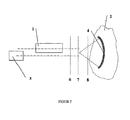
- Proximity detection in the case of rear projection where the projector and camera and possibly an auxiliary light source as described above, are located behind the projection screen, and where the projection screen is of the diffusing type, can for example utilize the preferred embodiment as shown in Fig. 7 .
- the invention relates to proximity detection and position determination.
- Proximity detection has generally an interest at many fields of use.
- Optical proximity detection based on the principle described, is particularly attractive since new camera technology and other modern optical sensors and illumination sources have become available.
- confocal microscopy should be mentioned, where the ray path for illumination (typically a laser) and to the light detector goes through the same lens system before and after incidence on the object to be microscoped.
- the invention makes possible the separation of the light detector and/or the light source from the target object and the reference object.
- the invention makes it possible by remote sensing to determine whether the target object and the references object are adjacent to each other. Also conditions of the target object can be interrogated by means of such remote sensing.
- the invention also provides apparatus as set out in the following numbered clauses:
Abstract
Description
- The invention relates to an apparatus that can detect when one or more target objects are in vicinity of their respective reference surfaces or reference objects.
- The invention also relates to a detection system that can cooperate with the apparatuses and can determine when one or more target objects are in vicinity of their respective reference surfaces or reference objects.
- Moreover, the invention relates to a method for determining when one or more target objects are in the vicinity of their respective reference surfaces or reference objects.
- There are today several known methods for determining whether a target object is in the vicinity of a reference surface or other reference object.
- Proximity detection is of interest, inter alia, in industrial, automotive and avionic systems. By means of proximity detectors the systems can report their own position relatively to reference objects and report conditions, as for example to determine the condition of valves (open, closed) provided with such proximity detectors. In automatic or autonomous systems the systems can themselves respond to the conditions of proximity detectors and other sensors, by changing speed or velocity direction, and possibly perform a series of different operations depending upon the state of the system as a whole.
- In general proximity detectors have the property that there is no requirement for physical contact between the said target object and the said reference object in order to determine that the two are close to each other. In some cases it is also decisive that there is no requirement for physical contact between the detector system and one or more of the two said objects, and that proximity detection accordingly is obtained by remote sensing. It may also be decisive that the equipment on the two said objects does not require any electrical or other energy. Moreover, it can be decisive that the equipment has a low weight. Besides it may be decisive that the equipment is simple and inexpensive to manufacture. In many cases it may be important that the equipment does not require any maintenance. Furthermore it is often important that the equipment or the measuring method does not have any influence on the target object or environments, for example by disturbing electric or magnetic fields. In use of medical equipment there will be a strict requirement that the equipment does not hurt the patient. The present invention satisfies all the above aims.
- A number of different proximity detector principles are known, for example based on ultra sound propagation distance measurement etc. (
US6114950 ,DE3235028 ,US5144593 ), triangulation with visible or invisible light (W09219984 US4752799 ), fibre optic sensors (US6498654 ), laser-based principles (DE2448898 ), magnetic principles (US6127821 ,US2003173957 ) etc. -
US 5,200,604 describes an optical proximity detector for a probe in a laser scalpel device. The proximity detector consists of a light source, a light conductor leading the light out to an output aperture and a light detector receiving light via a light conductor to an aperture in the vicinity of the output aperture. Proximity to a reference surface is calculated from the reflected light intensity. The purpose is to avoid the activation of a laser scalpel before there is contact with the tissue in which there is to be cut. -
US 4,991,509 describes a method and an apparatus for determining the spacing between an object and a reference surface. The proximity detector consists of a light source, a light conductor leading the light out to an output aperture, and a light detector receiving light via a light conductor to an aperture in the vicinity of the output aperture. The two apertures are spaced at a certain distance from each other so that the light cone emitted overlaps to a larger or smaller degree the field of view captured by the light detector through the input aperture. Proximity to a reference surface is calculated from the reflected light intensity. - The two patents
US 5,200,604 andUS 4,991,509 describe proximity detection by means of a principle wherein source and detection have a certain mutual spacing so that the light cone from the light source and the field of view of the light detector will cover a common volume or a common area on the reference object, that will vary depending upon the spacing between the target object and the reference surface, thereby representing a varying back-scattered light intensity. In contrast to the present invention, these patents do not comprise any lenses or curved mirrors with associated focal lengths that define the proximity detection. The patents do not describe any devices wherein the light cone of the light source and the field of view of the light detector are coincident; on the contrary a specified lateral spacing is required between the two apertures so that the light cone and the light detector will have a partially overlapping coverage area that in turn depends on the distance to the reference surface and where this variable overlap area gives a varying back-scattered light intensity that can be measured in the light detector. Thus, a prerequisite in the two patents is a lateral distance between input aperture and output aperture in order that the devices shall operate properly, whereas the present invention does not involve the requirement that input aperture and output aperture shall be separated by a lateral distance. - In the present invention the said target object and the said reference surface or reference object will be illuminated completely or in part by light, and this light has a spectrum within or outside the visible range. The light detector can be a camera with subsequent analogue and/or also digital signal processing and/or also digital image processing, or in a simpler embodiment can be composed of one or more optical photo detectors with associated detection electronics. The said illumination can be pulsed or modulated in order to be distinguished from other illumination, and such modulation can also be synchronised with the light detection. In the following the invention shall be explained more closely with reference to the accompanying drawings, wherein:
- Fig. 1
- illustrates an embodiment of the proximity detector.
- Fig. 2
- illustrates an embodiment of a system of proximity detectors having a common light source and common light detection with a camera and computer or a similar digital system for image acquisition, data processing, presentation, communication and operation of related software.
- Fig. 3
- illustrates an embodiment in which the light source is associated with the target object.
- Figs.4-7
- show various modifications of embodiments according to the invention.
-
Fig. 1 shows an embodiment of the proximity detector. The saidillumination source 1 and thesaid light detector 3 will have the most possible adjacent and the most possible parallel axes directed towards thetarget object 2, whereas the target object will be provided with a convex lens 4 (consisting of one or more lens elements, or in the alternative a sphere or a cylindrical rod) or a concave mirror (or a group of several mirrors with different curvatures), representing a specifiedfocal length 7. Proximity detection is obtained when such a lens-mirror configuration on such a target object has a distance to such a reference surface or reference object that corresponds to this specifiedfocal length 7, whereas the light is back-scattered to a small degree through the said lens mirror at alarger distance 8 or ashorter distance 6. Thereference surface - As a "receiver" (light detector) there may be contemplated a human eye (the operator's vision) instead of a camera or the like, the receiver arrangement being in such case designed for cooperation with an eye of the operator or user.
- In a preferred version the solution proposed will only have said lens-mirror arrangement or device mounted on the target object, whereas the illumination source and the detector are separated from the target object and the reference object. Moreover this illumination source and this detector can be separated from each other, as long as the detector is positioned at the axis of the back-scattered light from the lens-mirror arrangement. In another preferred version as illustrated in
Fig. 3 , theillumination source 1 can be located on thetarget object 2 whereas thelight detector 3 can be located at another stationary or movable point. In a third preferred version as illustrated inFig. 4 thedetector 3 is located on thetarget object 2 whereas the illumination source is located at another stationary or movable point. In a fourth preferred version as illustrated inFig. 5 both the detector and the illumination source are located on the target object. In a fifth preferred version as illustrated inFig. 6 aconcave mirror 4 is employed as a focusing optical element located on thetarget object 2. In a sixth preferred version as illustrated inFig. 7 aconcave mirror 4 is used as a focusing element located on thetarget object 2, and the target object is placed on the opposite side of a diffusing screen in relation to the light source and the detector. It is also possible to change the axis direction of the light detector in relation to the axis direction of the illumination source, by means of an extra mirror and/or other optical elements. Seevariants 3a-14 inFig. 3 . - An embodiment of a system for proximity determination and/or also
position determination 11 for use together with one or more devices 9 that make it possible to detect when one or more target objects are in the vicinity of theirrespective reference surfaces reference objects Fig. 2 . In this embodiment there is one or a plurality of proximity detectors having a common light source and common light detection by means of a camera, and a computer or similar digital system for image acquisition, data processing, presentation, communication and implementation of related software. Analogue and/or digital signal processing of the image pixels will often be necessary in order to obtain a reliable proximity detection, where also different reference levels are used and can also be estimated. - The invention relates to the general principle of proximity detection. As described above proximity detectors can have significant industrial possibilities within various fields of use. Application of new low cost camera technology and other modern optical solid-state sensors together with modern illumination sources such as lasers, laser diodes and light emitting diodes etc. that can readily be modulated or pulsed, give the principles a great use and profit potential. The uses can be where the dimensions to be monitored are large or where the distances are in the millimetre or micron range.
- In general the invention may be employed together with means for lateral position determination and determination of the orientation of target objects. The invention can be used together with the positioning and orientation principles of Norwegian patent No.
311740 PCT/NO01/00369 PCT/NO01/00369 - An example of an interesting particular use of the invention, is proximity detection of writing and pointing tools being employed in connection with data projectors. Such a system, that employs camera-viewing systems as a sensor and a data projector as illumination source, is described in Norwegian patent
311740 PCT/NO01/00369 311740 PCT/NO01/00369 - The invention may also be employed as a proximity detector in such a drawing, writing and pointing tool even if the principles for position determination and/or also orientation determination in the projector image plane according to the two above patents, are not utilized. The invention can also be used as a independent method or combined with one or more other methods of position determination.
- One of several preferred embodiments may be as shown in
Fig. 2 , but where the light source is a data projector and the light detector is a camera with digital detection electronics that is located adjacent to the data projector and with its axis as close as possible to parallel to the axis of the data projector. In a preferred embodiment the camera with its digital detection electronics is incorporated in the data projector. The system ofFig. 2 will be able to detect whether interaction means such as for example a drawing, writing or pointing tool is spaced from or is closely adjacent to the writing surface (for example a wall, a table, a board, a rear projection screen). The system onFig. 2 may also detect whether buttons or other adjustments of the drawing tool have be depressed or activated in another manner, by detecting distance/proximity between related target objects and reference objects. - Also proximity detection as described above, but where the light source is not necessarily a data projector, but an independent constant, pulsed or modulated light source with visible or invisible light, can supplement such systems in order to make these more robust and redundant.
- Proximity detection in the case of rear projection, where the projector and camera and possibly an auxiliary light source as described above, are located behind the projection screen, and where the projection screen is of the diffusing type, can for example utilize the preferred embodiment as shown in
Fig. 7 . - The invention relates to proximity detection and position determination. Proximity detection has generally an interest at many fields of use. Optical proximity detection based on the principle described, is particularly attractive since new camera technology and other modern optical sensors and illumination sources have become available. Also confocal microscopy should be mentioned, where the ray path for illumination (typically a laser) and to the light detector goes through the same lens system before and after incidence on the object to be microscoped.
- The invention makes possible the separation of the light detector and/or the light source from the target object and the reference object. Thus, the invention makes it possible by remote sensing to determine whether the target object and the references object are adjacent to each other. Also conditions of the target object can be interrogated by means of such remote sensing.
- Whereas several illustrative embodiments of the invention have been shown and/or described, there are of course a high number of variations and alternative embodiments being possible for experts in the field, while limitations of such variations and modifications are only related to the invention as it is stated in the claims.
- The invention also provides apparatus as set out in the following numbered clauses:
- 1. Apparatus for detecting proximity between a first object (target object) and a second object (reference object), comprising a light source (1) and a light detector (3) adapted to receive resulting back-scattered light from the reference object when illuminated from the light source (1), whereby the intensity of back-scattered light to the light detector (3) is utilized as a measure of said proximity,
characterized in that the target object (2) comprises an optical device (4) having a focal plane (7) and being adapted to be illuminated by the light source (1),
that the axes of the light rays from the light source (1) and the back-scattering to the light detector (3) have mutually closely adjacent and substantially parallel or coincident portions, and
that said proximity corresponds to a spacing (relative position) between the target object (2) and the reference object (6,8) wherein the reference object is located substantially at the focal plane. - 2. Apparatus according to
clause 1, wherein the light source (1) and/or the light detector (3) are/is located on the target object (2). - 3. Apparatus according to
clause - 4. Apparatus according to
clauses - 5. Apparatus according to any one of clauses 1-4, wherein the light detector comprises a camera (3).
- 6. Apparatus according to any one of clauses 1-5, wherein the optical device (4) has at least two focal planes for determination of said proximity in at least two relative positions of the target object (2) and the reference object (6,8).
- 7. Apparatus according to any one of clauses 1-6, wherein the intensity of back-scattered light to the light detector (3) is compared with a predetermined and preferably adjustable level, for detection of said proximity.
- 8. Apparatus according to any one of clauses 1-7, wherein the light source (1) and the light detector (3) are located separately in relation to one another.
- 9. Apparatus according to any one of clauses 1-8, wherein the light source consists of a data projector (
Fig. 2 ). - 10. Drawing, writing and/or pointing tool for data presentation, computer-supported work or interactive operations with a computer, wherein an apparatus according to any one of clauses 1-9 is incorporated in the tool.
- 11. Apparatus for detecting proximity between a first object (target object) and a second object (reference object), comprising a light source (1) and a receiver for resulting back-scattered light from the reference object when illuminated from the light source (1), whereby the intensity of back-scattered light to the receiver is utilized as a measure of said proximity,
CharacterIzed in that the target object (2) comprises an optical device (4) having a focal plane (7) and being adapted to be illuminated by the light source (1), that the axes of the light rays from the light source (1) and back-scattering to the receiver have mutually closely adjacent and substantially parallel or coincident portions, that said proximity corresponds to a distance (relative position) between the target object (2) and the reference object (6,8) wherein the reference object is located substantially at the focal plane, and that the receiver is adapted to cooperate with an eye belonging to a user of the apparatus. - 12. Apparatus according to
clause 11, wherein the light source consists of a data projector.
Claims (15)
- Apparatus for detecting proximity between a target object and a reference object, comprising a light source (1) and a light detector (3) adapted to receive resulting back-scattered light from the reference object when illuminated from the light source (1), whereby the intensity of back-scattered light to the light detector (3) is utilized as a measure of said proximity,
characterized in that the target object (2) comprises an optical device (4) having a focal plane (7) and being adapted to be illuminated by the light source (1),
that the axes of the light rays from the light source (1) and the back-scattering to the light detector (3) have mutually closely adjacent and substantially parallel or coincident portions, and
that said proximity corresponds to a relative position spacing between the target object (2) and the reference object (6,8) wherein the reference object is located substantially at the focal plane. - Apparatus according to claim 1, wherein either the light source (1) or the light detector (3) is separated from the target object (2).
- Apparatus according to claim 1 or claim 2 further comprising said target object, wherein the light source and detector are separated from the target object and the reference object, so as to detect said proximity by remote sensing.
- Apparatus according to any preceding claim, wherein said axes outside said portions have deviating directions, such as by using mirrors, optical fibres or light conductors.
- Apparatus according to any preceding claim, wherein the light source (1) is adapted to emit modulated or pulsed light, and the light detector (3) is synchronized with such modulation or pulsing.
- Apparatus according to any one of claims 1-5, wherein the light detector comprises a camera (3).
- Apparatus according to any one of claims 1-6, wherein the optical device (4) has at least two focal planes for determination of said proximity in at least two relative positions of the target object (2) and the reference object (6,8).
- Apparatus according to any one of claims 1-7, wherein the intensity of back-scattered light to the light detector (3) is compared with a predetermined and preferably adjustable level, for detection of said proximity.
- Apparatus according to any one of claims 1-8, wherein the light source (1) and the light detector (3) are located separately in relation to one another.
- Apparatus according to any one of claims 1-9, wherein the light source consists of a data projector.
- Apparatus according to any of claims 1 to 10 wherein the target object is a drawing, writing or pointing tool for data presentation, computer supported work or interactive operations with a computer.
- Apparatus of claim 11 comprising a plurality of said target objects.
- Apparatus of claim 11 or 12 further arranged to detect whether buttons or other adjustments of the target object have been depressed or activated in another manner, by detecting distance/proximity between one or more related target objects and reference objects.
- Apparatus of any preceding claim in combination with means for determination of lateral position and orientation of the target object or objects.
- Apparatus of any preceding claim wherein the light source is a data projector, and the light detector is a camera with its digital detection electronics incorporated into the data projector.
Applications Claiming Priority (2)
| Application Number | Priority Date | Filing Date | Title |
|---|---|---|---|
| NO20035142A NO320062B1 (en) | 2003-11-19 | 2003-11-19 | Device for detecting proximity between a first object (template object) and another object (reference object), as well as drawing, writing and / or pointing tools for data presentation etc. |
| EP04800195.2A EP1692459B1 (en) | 2003-11-19 | 2004-11-12 | Proximity detector |
Related Parent Applications (2)
| Application Number | Title | Priority Date | Filing Date |
|---|---|---|---|
| EP04800195.2A Division-Into EP1692459B1 (en) | 2003-11-19 | 2004-11-12 | Proximity detector |
| EP04800195.2 Division | 2004-11-12 |
Publications (1)
| Publication Number | Publication Date |
|---|---|
| EP2472218A1 true EP2472218A1 (en) | 2012-07-04 |
Family
ID=30439575
Family Applications (2)
| Application Number | Title | Priority Date | Filing Date |
|---|---|---|---|
| EP04800195.2A Expired - Fee Related EP1692459B1 (en) | 2003-11-19 | 2004-11-12 | Proximity detector |
| EP12155191A Withdrawn EP2472218A1 (en) | 2003-11-19 | 2004-11-12 | Proximity detector |
Family Applications Before (1)
| Application Number | Title | Priority Date | Filing Date |
|---|---|---|---|
| EP04800195.2A Expired - Fee Related EP1692459B1 (en) | 2003-11-19 | 2004-11-12 | Proximity detector |
Country Status (9)
| Country | Link |
|---|---|
| US (1) | US7339684B2 (en) |
| EP (2) | EP1692459B1 (en) |
| JP (2) | JP4832311B2 (en) |
| KR (1) | KR101109966B1 (en) |
| CN (1) | CN100437025C (en) |
| AU (1) | AU2004291813B2 (en) |
| CA (1) | CA2544600C (en) |
| NO (1) | NO320062B1 (en) |
| WO (1) | WO2005050130A1 (en) |
Families Citing this family (26)
| Publication number | Priority date | Publication date | Assignee | Title |
|---|---|---|---|---|
| US8494805B2 (en) | 2005-11-28 | 2013-07-23 | Orthosensor | Method and system for assessing orthopedic alignment using tracking sensors |
| US8169404B1 (en) | 2006-08-15 | 2012-05-01 | Navisense | Method and device for planary sensory detection |
| US7978091B2 (en) * | 2006-08-24 | 2011-07-12 | Navisense | Method and device for a touchless interface |
| US8421642B1 (en) | 2006-08-24 | 2013-04-16 | Navisense | System and method for sensorized user interface |
| US7961173B2 (en) * | 2006-09-05 | 2011-06-14 | Navisense | Method and apparatus for touchless calibration |
| US8316324B2 (en) * | 2006-09-05 | 2012-11-20 | Navisense | Method and apparatus for touchless control of a device |
| US8354997B2 (en) * | 2006-10-31 | 2013-01-15 | Navisense | Touchless user interface for a mobile device |
| US8904312B2 (en) * | 2006-11-09 | 2014-12-02 | Navisense | Method and device for touchless signing and recognition |
| US8793621B2 (en) * | 2006-11-09 | 2014-07-29 | Navisense | Method and device to control touchless recognition |
| US8060841B2 (en) * | 2007-03-19 | 2011-11-15 | Navisense | Method and device for touchless media searching |
| US20080252595A1 (en) * | 2007-04-11 | 2008-10-16 | Marc Boillot | Method and Device for Virtual Navigation and Voice Processing |
| US20080284726A1 (en) * | 2007-05-17 | 2008-11-20 | Marc Boillot | System and Method for Sensory Based Media Control |
| EP2247578B1 (en) * | 2008-01-09 | 2013-05-22 | Array Biopharma, Inc. | Hydroxylated pyrimidyl cyclopentanes as akt protein kinase inhibitors |
| US9189083B2 (en) | 2008-03-18 | 2015-11-17 | Orthosensor Inc. | Method and system for media presentation during operative workflow |
| US8324602B2 (en) * | 2009-04-14 | 2012-12-04 | Intersil Americas Inc. | Optical sensors that reduce specular reflections |
| US8258453B2 (en) * | 2009-04-29 | 2012-09-04 | Intersil Americas Inc. | Long range proximity and/or motion detector with ambient light detection capabilities |
| US9011448B2 (en) * | 2009-12-31 | 2015-04-21 | Orthosensor Inc. | Orthopedic navigation system with sensorized devices |
| GB2487043B (en) | 2010-12-14 | 2013-08-14 | Epson Norway Res And Dev As | Camera-based multi-touch interaction and illumination system and method |
| US8639400B1 (en) | 2012-09-26 | 2014-01-28 | Silverlit Limited | Altitude control of an indoor flying toy |
| CN104122541B (en) | 2013-04-28 | 2016-08-17 | 意法半导体研发(深圳)有限公司 | There is proximity detector equipment and the correlation technique of interconnection layer |
| US10198647B2 (en) * | 2015-09-25 | 2019-02-05 | Datalogic IP Tech, S.r.l. | Compact imaging module with range finder |
| CN105433983B (en) * | 2015-12-15 | 2019-01-22 | 北京汇影互联科技有限公司 | A kind of ultrasonic diagnostic equipment and the method for switching ultrasonic probe working condition |
| JP6629118B2 (en) * | 2016-03-30 | 2020-01-15 | 三菱重工業株式会社 | Optical sensor and rotating machine |
| US11073615B2 (en) * | 2018-08-20 | 2021-07-27 | Lite-On Singapore Pte. Ltd. | Proximity sensor module with two sensors |
| US20200100204A1 (en) * | 2018-09-21 | 2020-03-26 | Honeywell International Inc. | Location tracker |
| WO2021154550A1 (en) | 2020-01-31 | 2021-08-05 | American Sterilizer Company | Proximity detection for a surgical light |
Citations (17)
| Publication number | Priority date | Publication date | Assignee | Title |
|---|---|---|---|---|
| DE3235028A1 (en) | 1982-09-22 | 1984-03-22 | Josef 3150 Peine Teichmann | Proximity switching device |
| US4752799A (en) | 1986-07-07 | 1988-06-21 | Honeywell Inc. | Optical proximity sensing optics |
| US4991509A (en) | 1983-06-24 | 1991-02-12 | The United States Of America As Represented By The Secretary Of The Navy | Optical proximity detector |
| DE4013743A1 (en) * | 1990-04-28 | 1991-11-07 | Klaschka Ind Elektronik | Optical proximity switch - uses cylinder-mounted prism with axially-symmetrical faces to provide high precision adjustment |
| US5144593A (en) | 1990-11-05 | 1992-09-01 | Siemens Aktiengesellschaft | Integrated automatic control for ultrasonic proximity switches |
| WO1992019984A1 (en) | 1991-05-03 | 1992-11-12 | Valtion Teknillinen Tutkimuskeskus | Apparatus for locating an object, and light transmitter |
| US5200604A (en) | 1991-08-07 | 1993-04-06 | Laser Engineering, Inc. | Handpiece optical proximity detector for disabling surgical laser beam |
| US5448359A (en) * | 1991-12-04 | 1995-09-05 | Siemens Aktiengesellschaft | Optical distance sensor |
| US5504345A (en) * | 1994-04-14 | 1996-04-02 | Hama Laboratories, Inc. | Dual beam sensor and edge detection system and method |
| DE2448898C1 (en) | 1974-10-15 | 1998-05-14 | Telefunken Systemtechnik | Radar or laser based proximity detonator for shell or rocket |
| US6114950A (en) | 1999-05-03 | 2000-09-05 | Specam Technologies, Inc. | Obstacle proximity warning device for vehicles |
| US6127821A (en) | 1997-06-02 | 2000-10-03 | The Cherry Corporation | System for adjusting a magnetic sensor to detect the presence of ferrous objects |
| NO311740B1 (en) | 2000-09-11 | 2002-01-14 | Tormod Njoelstad | Drawing, writing and pointing tools for computer-based presentations and office work |
| US6498654B1 (en) | 1999-06-11 | 2002-12-24 | Harco Laboratories, Inc. | Optical proximity detector |
| US20030038950A1 (en) * | 2001-08-24 | 2003-02-27 | Reiner Spolaczyk | Apparatus for handling liquids and a process for operating the device |
| US20030085368A1 (en) * | 2001-11-08 | 2003-05-08 | Boris Kesil | Mapping sensor system for detecting postions of flat objects |
| US20030173957A1 (en) | 2001-08-29 | 2003-09-18 | Microlab, Inc. | Micro magnetic proximity sensor |
Family Cites Families (15)
| Publication number | Priority date | Publication date | Assignee | Title |
|---|---|---|---|---|
| DE3338807C2 (en) * | 1983-10-26 | 1989-02-02 | Klaus Hermle | Optoelectronic proximity switch |
| FR2560377B1 (en) * | 1984-02-29 | 1988-05-13 | Commissariat Energie Atomique | OPTICAL DEVICE FOR MEASURING SURFACE PROXIMITY AND ITS APPLICATION TO MEASURING A SURFACE PROFILE |
| JPS63259521A (en) * | 1987-04-16 | 1988-10-26 | Olympus Optical Co Ltd | Composite type focusing detection device |
| CN2070442U (en) * | 1990-08-12 | 1991-01-30 | 广西师范大学秀峰电器厂 | Non-contact photoelectric tracer |
| JPH04100015A (en) * | 1990-08-20 | 1992-04-02 | Toshiba Corp | Light projection device and photoscanning device |
| JPH06260393A (en) * | 1993-03-09 | 1994-09-16 | Hitachi Ltd | Positioning device |
| JP3461566B2 (en) * | 1994-05-25 | 2003-10-27 | 富士写真光機株式会社 | Interferometer for measuring cone shape |
| JPH09304684A (en) * | 1996-05-15 | 1997-11-28 | Citizen Watch Co Ltd | Converging type autofocusing method |
| JP3507262B2 (en) * | 1996-08-30 | 2004-03-15 | 松下電器産業株式会社 | Surface inspection equipment |
| JP3299144B2 (en) * | 1997-07-10 | 2002-07-08 | 住友重機械工業株式会社 | Position detecting apparatus and position detecting method applied to proximity exposure |
| JPH11192573A (en) * | 1998-01-08 | 1999-07-21 | Nissan Motor Co Ltd | Laser beam machine and processing method |
| JP3653419B2 (en) * | 1998-06-26 | 2005-05-25 | 松下電器産業株式会社 | projector |
| JP2000241874A (en) * | 1999-02-19 | 2000-09-08 | Nec Corp | Method and device for automatically adjusting screen position for projector |
| JP2002123953A (en) * | 2000-10-12 | 2002-04-26 | Hitachi Ltd | High density optical recorder |
| KR20010044477A (en) * | 2001-02-24 | 2001-06-05 | 최원하 | Apparatus and Method for mearsuring a distance using LASER |
-
2003
- 2003-11-19 NO NO20035142A patent/NO320062B1/en not_active IP Right Cessation
-
2004
- 2004-11-12 KR KR1020067008598A patent/KR101109966B1/en not_active IP Right Cessation
- 2004-11-12 EP EP04800195.2A patent/EP1692459B1/en not_active Expired - Fee Related
- 2004-11-12 CN CNB2004800341744A patent/CN100437025C/en not_active Expired - Fee Related
- 2004-11-12 WO PCT/NO2004/000347 patent/WO2005050130A1/en active Application Filing
- 2004-11-12 AU AU2004291813A patent/AU2004291813B2/en not_active Ceased
- 2004-11-12 CA CA2544600A patent/CA2544600C/en not_active Expired - Fee Related
- 2004-11-12 US US10/579,334 patent/US7339684B2/en not_active Expired - Fee Related
- 2004-11-12 EP EP12155191A patent/EP2472218A1/en not_active Withdrawn
- 2004-11-12 JP JP2006541064A patent/JP4832311B2/en not_active Expired - Fee Related
-
2011
- 2011-04-19 JP JP2011093177A patent/JP5461470B2/en not_active Expired - Fee Related
Patent Citations (17)
| Publication number | Priority date | Publication date | Assignee | Title |
|---|---|---|---|---|
| DE2448898C1 (en) | 1974-10-15 | 1998-05-14 | Telefunken Systemtechnik | Radar or laser based proximity detonator for shell or rocket |
| DE3235028A1 (en) | 1982-09-22 | 1984-03-22 | Josef 3150 Peine Teichmann | Proximity switching device |
| US4991509A (en) | 1983-06-24 | 1991-02-12 | The United States Of America As Represented By The Secretary Of The Navy | Optical proximity detector |
| US4752799A (en) | 1986-07-07 | 1988-06-21 | Honeywell Inc. | Optical proximity sensing optics |
| DE4013743A1 (en) * | 1990-04-28 | 1991-11-07 | Klaschka Ind Elektronik | Optical proximity switch - uses cylinder-mounted prism with axially-symmetrical faces to provide high precision adjustment |
| US5144593A (en) | 1990-11-05 | 1992-09-01 | Siemens Aktiengesellschaft | Integrated automatic control for ultrasonic proximity switches |
| WO1992019984A1 (en) | 1991-05-03 | 1992-11-12 | Valtion Teknillinen Tutkimuskeskus | Apparatus for locating an object, and light transmitter |
| US5200604A (en) | 1991-08-07 | 1993-04-06 | Laser Engineering, Inc. | Handpiece optical proximity detector for disabling surgical laser beam |
| US5448359A (en) * | 1991-12-04 | 1995-09-05 | Siemens Aktiengesellschaft | Optical distance sensor |
| US5504345A (en) * | 1994-04-14 | 1996-04-02 | Hama Laboratories, Inc. | Dual beam sensor and edge detection system and method |
| US6127821A (en) | 1997-06-02 | 2000-10-03 | The Cherry Corporation | System for adjusting a magnetic sensor to detect the presence of ferrous objects |
| US6114950A (en) | 1999-05-03 | 2000-09-05 | Specam Technologies, Inc. | Obstacle proximity warning device for vehicles |
| US6498654B1 (en) | 1999-06-11 | 2002-12-24 | Harco Laboratories, Inc. | Optical proximity detector |
| NO311740B1 (en) | 2000-09-11 | 2002-01-14 | Tormod Njoelstad | Drawing, writing and pointing tools for computer-based presentations and office work |
| US20030038950A1 (en) * | 2001-08-24 | 2003-02-27 | Reiner Spolaczyk | Apparatus for handling liquids and a process for operating the device |
| US20030173957A1 (en) | 2001-08-29 | 2003-09-18 | Microlab, Inc. | Micro magnetic proximity sensor |
| US20030085368A1 (en) * | 2001-11-08 | 2003-05-08 | Boris Kesil | Mapping sensor system for detecting postions of flat objects |
Also Published As
| Publication number | Publication date |
|---|---|
| JP5461470B2 (en) | 2014-04-02 |
| KR20060111482A (en) | 2006-10-27 |
| KR101109966B1 (en) | 2012-02-24 |
| AU2004291813B2 (en) | 2009-05-14 |
| WO2005050130A1 (en) | 2005-06-02 |
| EP1692459B1 (en) | 2017-03-15 |
| CA2544600C (en) | 2011-09-13 |
| AU2004291813A1 (en) | 2005-06-02 |
| CN1882820A (en) | 2006-12-20 |
| US7339684B2 (en) | 2008-03-04 |
| EP1692459A1 (en) | 2006-08-23 |
| CN100437025C (en) | 2008-11-26 |
| CA2544600A1 (en) | 2005-06-02 |
| NO320062B1 (en) | 2005-10-17 |
| NO20035142D0 (en) | 2003-11-19 |
| JP2011141296A (en) | 2011-07-21 |
| JP4832311B2 (en) | 2011-12-07 |
| NO20035142L (en) | 2005-05-20 |
| US20070127039A1 (en) | 2007-06-07 |
| JP2007514144A (en) | 2007-05-31 |
Similar Documents
| Publication | Publication Date | Title |
|---|---|---|
| EP1692459B1 (en) | Proximity detector | |
| US9018575B2 (en) | Non-retroreflective optical threat detection system and methods having an imaging detector aligned with a tilted image plane to reconstruct an image from plural image slices | |
| US20080174429A1 (en) | Motion sensor with LED aiming aid | |
| JP2004526198A (en) | Adjustable mirror for parallel beam laser sensor | |
| JP4533147B2 (en) | Proximity sensor | |
| US9696143B2 (en) | Device for optical profilometry with conical light beams | |
| US20170343337A1 (en) | Sensor device for measuring a surface | |
| KR20010041694A (en) | Optical sensor system for detecting the position of an object | |
| US20220276354A1 (en) | Rotating pyramidal mirror | |
| CN109073370A (en) | Use the depth sense of structured lighting | |
| JP4690316B2 (en) | Aiming device and measuring device that can be used without or in contact | |
| US4649270A (en) | Photo-electric object detector having removable field stop means | |
| EP0553698A1 (en) | Optical scanning device | |
| RU186704U1 (en) | Laser location device for a given area of space | |
| JP4034328B2 (en) | Luminescence detection device and coordinate detection device | |
| MXPA06005438A (en) | Proximity detector | |
| US6864964B2 (en) | Optical distance measuring device | |
| US11313953B2 (en) | Distance measuring module | |
| EP0204436A1 (en) | Light distribution and detection apparatus | |
| US6900730B2 (en) | Heat source locator | |
| WO2003060554A1 (en) | Indicator of optical and optoelectronic objects |
Legal Events
| Date | Code | Title | Description |
|---|---|---|---|
| AC | Divisional application: reference to earlier application |
Ref document number: 1692459 Country of ref document: EP Kind code of ref document: P |
|
| AK | Designated contracting states |
Kind code of ref document: A1 Designated state(s): AT BE BG CH CY CZ DE DK EE ES FI FR GB GR HU IE IS IT LI LU MC NL PL PT RO SE SI SK TR |
|
| PUAI | Public reference made under article 153(3) epc to a published international application that has entered the european phase |
Free format text: ORIGINAL CODE: 0009012 |
|
| RIN1 | Information on inventor provided before grant (corrected) |
Inventor name: NJOELSTAD, TORMOD |
|
| 17P | Request for examination filed |
Effective date: 20121219 |
|
| STAA | Information on the status of an ep patent application or granted ep patent |
Free format text: STATUS: THE APPLICATION HAS BEEN WITHDRAWN |
|
| 18W | Application withdrawn |
Effective date: 20171012 |