EP2453823B1 - Ophthalmic surgery measurement system - Google Patents
Ophthalmic surgery measurement system Download PDFInfo
- Publication number
- EP2453823B1 EP2453823B1 EP10800338.5A EP10800338A EP2453823B1 EP 2453823 B1 EP2453823 B1 EP 2453823B1 EP 10800338 A EP10800338 A EP 10800338A EP 2453823 B1 EP2453823 B1 EP 2453823B1
- Authority
- EP
- European Patent Office
- Prior art keywords
- eye
- light
- corneal surface
- target area
- scattered
- Prior art date
- Legal status (The legal status is an assumption and is not a legal conclusion. Google has not performed a legal analysis and makes no representation as to the accuracy of the status listed.)
- Active
Links
- 238000005259 measurement Methods 0.000 title description 137
- 238000001356 surgical procedure Methods 0.000 title description 9
- 230000003287 optical effect Effects 0.000 claims description 75
- 230000000007 visual effect Effects 0.000 claims description 17
- 238000003384 imaging method Methods 0.000 claims description 8
- 210000000695 crystalline len Anatomy 0.000 description 60
- 210000004087 cornea Anatomy 0.000 description 41
- 238000000034 method Methods 0.000 description 29
- 206010002945 Aphakia Diseases 0.000 description 23
- 230000002980 postoperative effect Effects 0.000 description 21
- 230000000875 corresponding effect Effects 0.000 description 13
- 230000004323 axial length Effects 0.000 description 11
- 238000012014 optical coherence tomography Methods 0.000 description 10
- 230000008569 process Effects 0.000 description 8
- 230000006870 function Effects 0.000 description 7
- 238000004364 calculation method Methods 0.000 description 6
- 238000004891 communication Methods 0.000 description 6
- 210000001525 retina Anatomy 0.000 description 6
- 230000007704 transition Effects 0.000 description 6
- 238000000611 regression analysis Methods 0.000 description 5
- 238000002604 ultrasonography Methods 0.000 description 5
- 238000002513 implantation Methods 0.000 description 4
- FAPWRFPIFSIZLT-UHFFFAOYSA-M Sodium chloride Chemical compound [Na+].[Cl-] FAPWRFPIFSIZLT-UHFFFAOYSA-M 0.000 description 3
- 210000002159 anterior chamber Anatomy 0.000 description 3
- 230000002596 correlated effect Effects 0.000 description 3
- 239000003190 viscoelastic substance Substances 0.000 description 3
- 208000002177 Cataract Diseases 0.000 description 2
- 238000004458 analytical method Methods 0.000 description 2
- 238000013507 mapping Methods 0.000 description 2
- 210000001747 pupil Anatomy 0.000 description 2
- 206010020675 Hypermetropia Diseases 0.000 description 1
- 210000001742 aqueous humor Anatomy 0.000 description 1
- 230000015572 biosynthetic process Effects 0.000 description 1
- 230000008859 change Effects 0.000 description 1
- 238000005516 engineering process Methods 0.000 description 1
- 238000003780 insertion Methods 0.000 description 1
- 230000037431 insertion Effects 0.000 description 1
- 230000001788 irregular Effects 0.000 description 1
- 230000007257 malfunction Effects 0.000 description 1
- 238000012986 modification Methods 0.000 description 1
- 230000004048 modification Effects 0.000 description 1
- 208000001491 myopia Diseases 0.000 description 1
- 238000012545 processing Methods 0.000 description 1
- 238000011160 research Methods 0.000 description 1
- 239000000523 sample Substances 0.000 description 1
- 238000005070 sampling Methods 0.000 description 1
- 238000000926 separation method Methods 0.000 description 1
- 238000001429 visible spectrum Methods 0.000 description 1
Images


Classifications
-
- A—HUMAN NECESSITIES
- A61—MEDICAL OR VETERINARY SCIENCE; HYGIENE
- A61B—DIAGNOSIS; SURGERY; IDENTIFICATION
- A61B3/00—Apparatus for testing the eyes; Instruments for examining the eyes
- A61B3/10—Objective types, i.e. instruments for examining the eyes independent of the patients' perceptions or reactions
- A61B3/1005—Objective types, i.e. instruments for examining the eyes independent of the patients' perceptions or reactions for measuring distances inside the eye, e.g. thickness of the cornea
-
- A—HUMAN NECESSITIES
- A61—MEDICAL OR VETERINARY SCIENCE; HYGIENE
- A61B—DIAGNOSIS; SURGERY; IDENTIFICATION
- A61B3/00—Apparatus for testing the eyes; Instruments for examining the eyes
- A61B3/0008—Apparatus for testing the eyes; Instruments for examining the eyes provided with illuminating means
-
- A—HUMAN NECESSITIES
- A61—MEDICAL OR VETERINARY SCIENCE; HYGIENE
- A61F—FILTERS IMPLANTABLE INTO BLOOD VESSELS; PROSTHESES; DEVICES PROVIDING PATENCY TO, OR PREVENTING COLLAPSING OF, TUBULAR STRUCTURES OF THE BODY, e.g. STENTS; ORTHOPAEDIC, NURSING OR CONTRACEPTIVE DEVICES; FOMENTATION; TREATMENT OR PROTECTION OF EYES OR EARS; BANDAGES, DRESSINGS OR ABSORBENT PADS; FIRST-AID KITS
- A61F2/00—Filters implantable into blood vessels; Prostheses, i.e. artificial substitutes or replacements for parts of the body; Appliances for connecting them with the body; Devices providing patency to, or preventing collapsing of, tubular structures of the body, e.g. stents
- A61F2/02—Prostheses implantable into the body
- A61F2/14—Eye parts, e.g. lenses, corneal implants; Implanting instruments specially adapted therefor; Artificial eyes
- A61F2/16—Intraocular lenses
-
- A—HUMAN NECESSITIES
- A61—MEDICAL OR VETERINARY SCIENCE; HYGIENE
- A61F—FILTERS IMPLANTABLE INTO BLOOD VESSELS; PROSTHESES; DEVICES PROVIDING PATENCY TO, OR PREVENTING COLLAPSING OF, TUBULAR STRUCTURES OF THE BODY, e.g. STENTS; ORTHOPAEDIC, NURSING OR CONTRACEPTIVE DEVICES; FOMENTATION; TREATMENT OR PROTECTION OF EYES OR EARS; BANDAGES, DRESSINGS OR ABSORBENT PADS; FIRST-AID KITS
- A61F9/00—Methods or devices for treatment of the eyes; Devices for putting-in contact lenses; Devices to correct squinting; Apparatus to guide the blind; Protective devices for the eyes, carried on the body or in the hand
- A61F9/007—Methods or devices for eye surgery
- A61F9/008—Methods or devices for eye surgery using laser
-
- A—HUMAN NECESSITIES
- A61—MEDICAL OR VETERINARY SCIENCE; HYGIENE
- A61F—FILTERS IMPLANTABLE INTO BLOOD VESSELS; PROSTHESES; DEVICES PROVIDING PATENCY TO, OR PREVENTING COLLAPSING OF, TUBULAR STRUCTURES OF THE BODY, e.g. STENTS; ORTHOPAEDIC, NURSING OR CONTRACEPTIVE DEVICES; FOMENTATION; TREATMENT OR PROTECTION OF EYES OR EARS; BANDAGES, DRESSINGS OR ABSORBENT PADS; FIRST-AID KITS
- A61F2240/00—Manufacturing or designing of prostheses classified in groups A61F2/00 - A61F2/26 or A61F2/82 or A61F9/00 or A61F11/00 or subgroups thereof
- A61F2240/001—Designing or manufacturing processes
- A61F2240/002—Designing or making customized prostheses
Definitions
- Embodiments of the invention relate generally to systems for performing ophthalmic measurements.
- some embodiments can be used for measuring a spatial distance in a patient's eye such as, for example, the distance between the corneal surface and the posterior wall of the capsular bag in an aphakic eye.
- Various ophthalmic procedures involve measurements of a spatial distance within a patient's eye, including measurements of the dimensions of the eye, or dimensions of features of the eye, the distance between selected portions or features of the eye, etc.
- measurements can be of the anterior chamber depth (ACD), lens thickness, and axial length of the eye.
- ACD anterior chamber depth
- Techniques for making certain types of these measurements include ultrasonic measuring and Optical Coherence Tomography (OCT).
- U.S. patent US 4,019,813 A discloses an optical apparatus for obtaining one or more measurements of portions of an eye having means for providing a narrow beam of light through the eye, a lens system that collects light that is reflected from the eye and forms an image on the surface of a television camera tube, and means for determining when the narrow beam of light passes through the center of curvature of the cornea and when the instrument is correctly positioned for proper focus on the eye.
- the ophthalmic apparatus can include a first laser configured to direct a first beam of light into an eye of a patient at a first non-zero angle with respect to an optical axis of the apparatus, such that the first beam of light propagates to a target area within the eye, and such that a portion of the first beam of light is scattered by the target area.
- the apparatus can also include imaging optics positioned to receive light scattered by the target area, and the imaging optics can define the optical axis of the apparatus.
- the apparatus can also include a photosensitive element, wherein the imaging optics direct the light scattered from the target area to the photosensitive element.
- the apparatus can also include a processor configured to determine a distance between the cornea of the eye and the target area within the eye based at least in part on the light received by the photosensitive element.
- Various embodiments disclosed herein include a method of determining the optical power for an intraocular lens to be implanted into an eye.
- the method can include measuring an intraoperative characteristic of the eye.
- the intraoperative characteristic can include the distance between selected first and second portions of the eye.
- the method can also include determining the optical power for the intraocular lens based at least in part on the measured intraoperative characteristic.
- Various embodiments disclosed herein include a method of using an ophthalmic apparatus.
- the method can include positioning the ophthalmic apparatus at a predetermined position over an eye of a patient, wherein an optical axis of the apparatus intersects the cornea of the eye.
- the method can include directing light from one or more lasers positioned about the optical axis of the apparatus into the eye so that a portion of the light from the one or more lasers is scattered by a target area inside the eye.
- the method can include directing a portion of the light scattered by the target area to a photosensitive element using imaging optics that define the optical axis.
- the method can include forming one or more target spots on the photosensitive element, and the one or more target spots can correspond to the light from the respective one or more lasers scattered by the target area.
- the method can also include calculating the distance between the cornea of the eye and the target area based at least in part on the positions of the one or more target spots.
- a device according to the invention is defined in claim 1.
- IOL intraocular lens
- a surgeon removes the natural crystalline lens from a patient's eye and an IOL is implanted in its place.
- IOL implantation surgery can be performed, for example, on a patient suffering from cataracts.
- an eye that prior to the surgery was, for example, myopic (near sighted), hyperopic (far sighted), and/or astigmatic can be restored to an emmetropic condition.
- the appropriate power for the IOL such as 1) the axial length of the eye, measured from the corneal surface to the retina; 2) the total optical power of the cornea; 3) the desired postoperative optical power (e.g., 0.0 diopters (D) for an emmetropic eye); and the effective lens position (ELP) of the IOL, which can be understood, for example, as the distance from the corneal surface to the post-operative position of the IOL.
- the axial length of the eye can be measured preoperatively (e.g., before the patient has been located on the operating table in a supine position), for example, by an ultrasound device or by Optical Coherence Tomography (OCT).
- the optical power of the cornea can be estimated from the corneal curvature values (Ks) of the eye measured preoperatively by a keratometer.
- Ks corneal curvature values
- the total refractive power of the aphakic eye which is a function of corneal curvature and axial length of the eye, can be measured intraoperatively and used in the IOL power calculation.
- the ELP of the IOL has traditionally been difficult to determine.
- the ELP of the IOL can be estimated based on preoperative data, but such estimates are limited in their accuracy.
- the limited accuracy of ELP estimates based on preoperative data can be attributed, at least in part, to the implanted IOL being positioned in the capsular bag differently than the natural crystalline lens.
- Preoperative measurements of the crystalline lens position do not always correlate well with the actual postoperative position of the IOL.
- Cataractous crystalline lenses vary in shape and size from individual to individual.
- preoperative measurements e.g., the ACD, which can be understood as, for example, the distance from the corneal surface to the anterior lens surface plus half the lens thickness
- the ACD which can be understood as, for example, the distance from the corneal surface to the anterior lens surface plus half the lens thickness
- the ELP for an IOL Given the sometimes-insufficient level of correlation between estimates of the ELP for an IOL and characteristics of the eye that can be measured preoperatively (e.g., corneal curvature, axial length, etc.), it would be desirable to estimate the ELP for the IOL based on characteristics of the eye that are more closely correlated with ELP, such as certain intraoperative characteristics of the eye.
- One such intraoperative characteristic of the eye is the location of the aphakic capsular bag within the eye (e.g., the longitudinal distance from the anterior corneal apex to the posterior wall of the aphakic capsular bag).
- the location of the aphakic capsular bag is an example of an intraoperative characteristic of the eye that is believed to be more closely correlated with the ELP of the IOL than are the preoperative characteristics of the eye from which the Holladay 1, SRK/T, Hoffer Q, Holladay 2, and Hagis formulas estimate the ELP of the IOL. This is at least in part due to the fact that an aphakic measurement of the distance from the cornea to the posterior wall of the capsular bag is not tainted by the irregular size and shape of the caratactous lens. Regression analysis can be used to establish the correlation between the location of the aphakic capsular bag and the postoperative position of the IOL.
- the ELP can be calculated by subtracting a constant from the measured distance from the cornea to the posterior wall of the aphakic capsular bag, wherein the constant is determined by the -regression analysis of postoperative IOL lens position or other outcome analysis.
- Various other formulas can be used to calculate the ELP.
- an ophthalmic apparatus to perform intraoperative measurements of spatial distances of/within a patient's eye. These intraoperative measurements are measurements of the patient's aphakic eye. These intraoperative measurements are used to calculate an improved estimate of the ELP of the IOL, the improved estimate being a result of closer correlation between the intraoperative measurement and the ELP of the IOL than the correlation between preoperative measurements and the ELP of the IOL.
- the ophthalmic apparatus measures a distance between the cornea and the aphakic capsular bag. This distance is between a selected position or portion of the cornea and a selected position or portion of the aphakic capsular bag.
- the selected portion of the cornea can be, for example, the location on the corneal surface where the visual axis of the eye intersects the corneal surface and/or the location where the corneal surface is perpendicular to the visual axis.
- the selected portion of the cornea can be other locations as well, such as the corneal apex.
- the selected portion of the capsular bag can be, for example, all or a portion of its posterior wall, all or a portion of its anterior wall, etc.
- the ophthalmic apparatus measures the aphakic capsular bag depth which can be understood, for example, as the distance from the cornea of the eye to the posterior or anterior surface of the capsular bag in an aphakic eye.
- An aphakic eye is an eye in which the lens of the eye is absent, while a phakic eye has the natural crystalline lens contained therein.
- the ophthalmic apparatus can be used during an IOL implantation surgery after the natural crystalline lens has been removed from the eye.
- the measured aphakic capsular bag depth can be used to predict the postoperative position of the IOL with greater accuracy than traditional methods, allowing the surgeon to more accurately calculate the appropriate power for the IOL to be implanted during the surgical procedure.
- the actual IOL postoperative position can be measured after the IOL has been implanted (e.g., using OCT or an ultrasound device), and that data can be used to improve the correlation between aphakic capsular bag depth and postoperative IOL position.
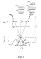
- FIG. 1 schematically illustrates an embodiment of an ophthalmic measurement system 100 for measuring dimensions of or in a patient's eye 102.
- the ophthalmic measurement system 100 is shown configured to measure the distance y 1 between the corneal surface 104 of the eye 102 and the posterior wall of the capsular bag 106.
- the eye is aphakic, the natural crystalline lens having been removed from the eye beforehand, such as during an IOL implantation surgery procedure. This measurement can be performed, for example, intra-operatively before or after the globe and capsular bag have been inflated (e.g., with basic saline solution or visco-elastic material).
- a three-dimensional coordinate system can be defined having a y-axis parallel to the visual axis of the patient's eye 102, and x- and z-axes that are mutually orthogonal to the y-axis so that the x- and z-axes define a plane that is perpendicular to the visual axis of the eye.
- lateral positioning of the ophthalmic measurement system 100 corresponds to the x and z coordinates of the ophthalmic measurement system 100
- longitudinal positioning corresponds to the y coordinate of the ophthalmic measurement system 100. It should be understood that the coordinate system described is for illustrative purposes only and other coordinate systems and other configurations can be used.
- the y-axis can be parallel with the optical axis of the patient's eye 102 and the x- and z-axes can define a plane that is perpendicular to the optical axis of the patient's eye 102.
- the ophthalmic measurement system 100 can include optics system 112 for collecting, directing, and/or focusing light that is scattered by the eye 102 during a measurement process.
- the optics system 112 can define an optical axis 114 of the ophthalmic measurement system 100.
- the ophthalmic measurement system 100 can be positioned at a predetermined position relative to the patient's eye 102.
- the ophthalmic measurement system 100 can be positioned laterally so it is centered over the pupil of the eye, and/or so that the optical axis 114 is substantially collinear with the visual or optical axis of the eye 102.
- the ophthalmic measurement system 100 can be positioned longitudinally so that it is located at a predetermined distance from the eye 102.
- the ophthalmic measurement system 100 can be used in conjunction with a positioning system (not shown in FIG. 1 ) for accurately positioning the ophthalmic measurement system 100 at the desired position.
- the ophthalmic measurement system 100 can include a pair of lasers 108, 110 oriented to direct light into the patient's eye.
- the lasers 108, 110 produce light that is outside of the visible spectrum (e.g., infrared light).
- the lasers 108, 110 produce beams of light having a width of at least about 200 microns and/or less than about 1000 microns, although widths outside this range may also be used.
- the lasers 108, 110 can be positioned on opposite sides of the optical axis 114, and can be separated by a distance x 2 .
- the lasers 108, 110 are positioned so that the optical axis 114 is located substantially at a midpoint between the lasers 108, 110, though this is not required. In some embodiments, the lasers 108, 110 are separated by a distance of at least about 60 mm and/or less than about 80 mm, although distances outside this range can also be used.
- the lasers 108, 110 when positioned at the desired location with respect to the eye 102, are located at a distance y 2 from the corneal surface of the eye. In some embodiments, the lasers 108, 110 can be positioned at a distance of at least about 100 mm and/or less than about 150 mm from the corneal surface 104, although distances outside this range can also be used. In an example embodiment, the lasers 108, 110 are positioned about 128 mm from the corneal surface 104 of the eye 102. In some embodiments, the lasers 108, 110 are positioned substantially equidistant from the eye 102. In other embodiments, one laser (e.g., 108) is positioned closer to the eye 102 than the other laser (e.g., 110).
- the lasers 108, 110 are oriented so that their respective emitted beams 116, 118 are coplanar.
- the lasers 108, 110 can be oriented (e.g., based on a predetermined distance y 2 ) so that the beam of light 116 emitted by the laser 108 is directed along a path that intersects the corneal surface 104 of the eye 102 at the location where the visual axis of the eye intersects the corneal surface 104, and so that the beam of light 118 emitted by the laser 110 is directed along a path that intersects the cornea of the eye at the corneal location where the visual axis of the eye intersects the corneal surface 104.
- the beams of light 116, 118 emitted by the lasers 108, 110 can intersect at the center of the corneal surface 104 of the eye 102.
- the lasers 108, 110 can be oriented so as to emit the beams of light 116, 118 at a non-zero angle ⁇ with respect to the optical axis 114.
- the beams of light 116, 118 deviate from the optical axis 114 by an angle of at least about 13° and/or less than about 17°, although angles outside this range may also be used.
- the beams of light 116, 118 emitted by the lasers 108, 110 deviate from the optical axis 114 by substantially the same amount, but in substantially opposite directions, though the angle between each beam and the optical axis 114 need not be identical. In some embodiments, the angles by which the beams of light 116, 118 deviate from the optical axis are within 10°, 5°, 3°, 2°, 1 °, or less of each other.
- the beams of light 116, 118 enter the eye 102 at the corneal surface 104, a portion of the light is scattered by the corneal surface 104, and a portion of the light propagates through the cornea and into the eye 102.
- the beam of light 116 strikes the posterior wall of the capsular bag 106 at a first location 120, and a portion of the beam of light 116 is scattered by the posterior wall of the capsular bag 106.
- the beam of light 118 strikes the posterior wall of the capsular bag 106 at a second location 122, and a portion of the second beam of light 118 is scattered by the posterior wall of the capsular bag 106.
- the optics system 112 can collect a portion of the scattered light and can direct the collected light to a detector 124.
- the optics system 112 is configured to focus the scattered light onto the detector 124.
- the optics system 112 can form an image on the detector 124.
- the optics system 112 is designed such that the detector 124 and the posterior wall of the capsular bag 106 are located at conjugate planes.
- the optics system 112 can include various optical elements, such as mirrors, lenses, filters, apertures, and beam splitters.
- the optical axis 114 is not necessarily a straight line along the entire optical path within the ophthalmic measurement system 100 as it may be bent by various optical elements within the optics system 112.
- the detector 124 can comprise a charge-coupled device (CCD) or other type of photosensitive element.
- the detector 124 includes a two-dimensional array of light-sensitive pixels configured to generate an electric signal that is descriptive of the light that strikes the pixels.
- a CCD sensor measuring 16 mm by 16 mm and having a two-dimensional array of 500 by 500 pixels can be used, although other configurations are also possible.
- the detector 124 can provide the electric signal to a processor 126.
- the processor 126 can be configured to process the data received from the detector 124 as described herein.
- the processor 126 can be in electronic communication with a suitable memory 128 for storing accumulated data, instructions to be executed by the processor 126, parameters relating to the patient's eye 102, or other data.
- the processor 126 can also be in electronic communication with a user interface 142 to allow the user to input information regarding the patient's eye (e.g., aphakic or phakic), information regarding the distance to be measured, or other information.
- FIG. 2 shows an example image 130 that can be formed on the detector 124 during a measurement process.
- FIG. 2 includes a coordinate system similar to the coordinate system shown in FIG. 1 .
- FIG. 2 shows the image 130 as being formed on the detector 124 in the x-z plane, the detector 124 can be oriented differently.
- the image 130 can include a center spot 132 corresponding to the light scattered at the corneal surface 104, a first target spot 134 corresponding to the light of the beam 116 scattered by the first location 120, and a second target spot 136 corresponding to the light of the beam 118 scattered by the second location 122.
- the optics system 112 can be configured so as to provide a depth of field that is large enough so that the center spot 132 and both of the target spots 134, 136 are in focus so as to provide sharp focused spots on the detector 124.
- the optics system can be configured so that one or more of the spots 132, 134, 136 is in focus and one or more of the spots 132, 134, 136 is appreciably out of focus.
- the center spot 132 can be appreciably out of focus while the target spots 134, 136 are in focus.
- the processor 126 can be configured to analyze the data received from the detector 124 and to determine therefrom a measurement of the distance y 1 , for example. In some embodiments, this analysis may include locating the centroid of one or more of the spots 132, 134, 136 to be used in the measurement process and determining the distance between two or more of the spots 132, 134, 136.
- the processor 126 is configured to calculate the distance y 1 from the corneal surface 104 to the posterior wall of the capsular bag 106 based at least in part on the data received from the detector 124.
- the processor 126 can calculate the distance x 1 between the locations 120, 122 based on the positions of the target spots 134, 136 (e.g:, the centroids of the spots) in the image 130.
- the processor 126 can determine the number of pixels between the locations of the target spots 134, 136 and apply an algorithm that calculates the real-world distance between the locations 120, 122 represented by the target spots 134, 136.
- the algorithm can account for any magnification provided by the optics system 112.
- any refraction of the beams of light 116, 118 as they enter the eye and as they pass through the various optical transitions within the eye can be ignored, so that each of the beams of light 116, 118 can be treated as though it propagates from the corneal surface 104 to the posterior wall of the capsular bag 106 at the same non-zero angle ⁇ with respect to the optical axis 114.
- the angle ⁇ is not known, but the distance x 2 of separation between the lasers 108, 110 and the distance y 2 from the lasers to the corneal surface 104 are known.
- the calculations for determining the distance y 1 can be adjusted to account for refraction of the beams of light as they enter the eye and/or as they propagate through the various refractive index transitions within the eye.
- the anterior chamber depth can be understood, for example, as the distance from the cornea to the anterior surface of the crystalline lens in a phakic eye. This distance can be between a selected position or portion of the cornea and a selected position or portion of the natural crystalline lens.
- the selected portion of the cornea can be, for example, the location on the corneal surface that intersects the visual axis of the eye.
- the selected portion of the crystalline lens can be, for example, all or a portion of its anterior surface of the lens, etc.
- the portion of the anterior surface can be, for example, the most anterior portion of the anterior surface, the position where the visual axis or the optical axis of the eye intersects the anterior surface, etc.
- FIG 3 schematically shows an embodiment of an ophthalmic measurement system 200 for measuring dimensions of or in a patient's eye including, for example, the anterior chamber depth (ACD) in a phakic eye 202.
- the ophthalmic measurement system 200 can be similar in some ways to the ophthalmic measurement system 100 discussed above, some of the disclosure of which applies also the ophthalmic measurement system 200, though some differences are identified below. Accordingly, in some embodiments, for example, the ophthalmic measurement system 200 can be the same ophthalmic measurement system 100 used to measure the posterior capsular bag depth in an aphakic eye (as shown in FIG. 1 ), with or without modifications in configuration.
- the ophthalmic measurement system 200 can include lasers 208, 210 configured to direct respective beams of light 216, 218 into the eye 202 of the patient through the corneal surface 204.
- the beams of light 216, 218 can therefore cross at the corneal surface 204 where a portion of the light from each of the beams 216, 218 is scattered by the corneal surface 204.
- the first beam of light 216 can propagate to a first location 220 on the anterior surface of the crystalline lens 206, which scatters a portion of light.
- the second beam of light 218 can propagate to a second location 222 on the anterior surface of the crystalline lens 206, which scatters a portion of the light.
- a portion of the light scattered by the corneal surface 204 and the first and second locations 220, 222 can be collected by the optics system 212 and directed to the detector 224.
- the optics system 212 or detector 224 can be especially configured for use with light reflected from the crystalline lens 206.
- the optics system 212 can be configured to focus light differently than the optics system 112 used to measure the posterior capsular bag depth in an aphakic eye to accommodate for the different object distance.
- the same optics system 112 and detector 124 can be used to measure the posterior capsular bag depth in an aphakic eye as well as the ACD in a phakic eye with or without the need for adjustments.
- FIG. 4 shows an example image 230 formed on the detector 224 during a measurement process.
- FIG. 4 includes a coordinate system similar to the coordinate system shown in FIG. 2 .
- the image 230 includes a center spot 232 corresponding to the light scattered at the corneal surface 204, a first target spot 234 corresponding to the light scattered by the first location 220 on the crystalline lens 206, and a second target spot 236 corresponding to the light scattered by the second location 222 on the crystalline lens 206.
- the processor 226 can be configured to calculate the distance y 1 ' based on the locations of the spots 232, 234, 236 in a manner similar to that discussed above. It should be noted that the target spots 234, 236 may be slightly closer together than the target spots 134, 136, indicating that the distance y 1 ' being measured by the image 230 is shorter than the distance y 1 being measured by the image 130.
- the anterior aphakic capsular bag depth can be measured.
- This distance can be understood as, for example, the distance between the corneal surface and the anterior surface of the aphakic capsular bag.
- This measurement can be performed, for example, intra-operatively after the natural crystalline lens has been removed but before or after the globe and capsular bag have been inflated (e.g., with basic saline solution or visco-elastic material).
- This distance can be used, for example, separately from, or in conjunction with, the posterior aphakic capsular bag depth for calculating the ELP for an IOL.
- the estimated ELP can be selected to be some fraction of the way between these two distances.
- Other relationships relating these two distances to the estimated ELP of an IOL in the capsular bag are also possible and can be determined by, for example, regression analysis, as described herein.
- the anterior capsular bag depth measurement can be used for calculating the predicted position of a sulcus lens.
- the estimated ELP of a sulcus lens could be related to the distance from the corneal surface to the anterior surface of the capsular bag by subtracting an empirically-derived constant from the measured distance.
- Other relationships relating this distance to the estimated ELP of a sulcus lens are also possible and can be determined by, for example, regression analysis, as described herein.
- the distance between the corneal surface 204 and the posterior wall of the capsular bag can be measured in the phakic eye 202 using light scattered by locations 238, 240 where the beams of light 216, 218 strike the posterior wall of the capsular bag.
- the image 230 formed on the detector 224 can include more spots than those shown in FIG. 4 .
- the image may also include spots corresponding to light scattered by the locations 238, 240 on the posterior surface of the capsular bag, or by other structures within the eye.
- the processor 226 can be configured to identify the spots relevant to the desired measurement, and ignore other spots in the image.
- the processor 224 can disregard spots outside of a feasible range for the desired measurement or only consider spots that are sufficiently bright or sufficiently in focus.
- the optics system 212 can have a relatively short depth of field and be configured to focus only the spots in the feasible range for the desired measurement.
- the processor 226 can adjust the calculations, the optics system 212, or other components of the ophthalmic measurement system 200 based on information received via the user interface 242 regarding the patient's eye 202 or the measurement to be performed. For example, because the refractive power of an aphakic eye is different than the refractive power of the corresponding phakic eye, in some embodiments, the measurement system 200 can adjust the optics system 212 (e.g., by adjusting the position of lenses) to change the focal length of the camera depending on whether the eye being measured is phakic or aphakic.
- Such adjustments can be used to compensate for the varying extent to which the refractive power of a phakic or aphakic eye causes scattered light (e.g., from the anterior surface of the natural lens or from the posterior surface of the aphakic capsular bag) to be converged or diverged prior to exiting the eye and being collected by the optics system 112.
- scattered light e.g., from the anterior surface of the natural lens or from the posterior surface of the aphakic capsular bag
- the lasers can be positioned at different longitudinal distances from the eye, or at different distances from the optical axis defined by the optics system. In some embodiments the lasers can be oriented at different angles with respect to the optical axis defined by the optics system. In some embodiments, the lasers can be positioned so that they cross at a location on the cornea that is not intersected by the visual axis of the eye or so that they cross at some other structure of the eye that is relevant to the desired measurement.
- FIG. 5 shows an example image 330 formed on a detector in an ophthalmic measurement system similar to those of FIGS. 1 and 3 but with a single laser.
- FIG. 5 includes a coordinate system similar to the coordinate system described in connection with FIG. 2 above.
- the image 330 includes a center spot corresponding to light scattered at, for example, the corneal surface of the eye.
- the image also includes a target spot 334 corresponding to light scattered by, for example, the posterior wall of the capsular bag in an aphakic eye.
- the distance y 1 " (which can be the same distance as y 1 shown in FIG.
- FIG. 6 shows an example image 430 formed on a detector of an ophthalmic measurement system similar to those of FIGS. 1 and 3 but with four lasers.
- FIG. 6 includes a coordinate system similar to the coordinate system described in connection with FIG. 2 above.
- the center spot corresponds to light scattered at the corneal surface of the eye.
- the four target spots 434, 435, 436, 437 correspond to the light from the respective four beams of light that is scattered at, for example, the posterior wall of the capsular bag.
- the distance between the corneal surface and the posterior wall of the capsular bag may then be determined based in part on the distance between the first target spot 434 and third target spot 436 and the distance between the second target spot 435 and the fourth target spot 437.
- the use of four lasers can provide information about the desired measurement along two axes, which in some embodiments may be orthogonal, as illustrated in FIG. 6 . For example, if the distance between the first and third target spots 434, 436 is less than the distance between the second and fourth target spots 435, 437, that can indicate that the distance to be measured is shorter along the axis measured by the first and third target spots 434, 436 than along the axis measured by the second and fourth target spots 435, 437.
- additional lasers can be used to gather additional data regarding the surface being measured.
- a grid of 8, 12, 16, or other number of lasers can be used to measure the distance from the corneal surface to the surface being measured at varying distances from the visual axis of the eye.
- the measuring system can be used to generate a more complete mapping of the surface of, for example, the posterior wall of the capsular bag, allowing for a more accurate prediction of the postoperative position of the IOL and thus a more accurate selection of IOL power.
- the measurements conducted by the various sets of lasers in the grid can be performed at different times to prevent overlap of target spots on the detector.
- the lasers can be movable (e.g., using gimbals and linear slides) and can be used to take measurements from multiple locations, so that a relatively thorough mapping of the surface can be obtained using a small number of lasers.
- the processor can determine whether the ophthalmic measurement system (e.g., 100, 200) is properly positioned at the desired location relative to the patient's eye based in part on the spots formed on the detector of the measurement system.
- FIG. 7A shows an example image 530 formed on the detector in an ophthalmic measurement system similar to those of FIGS. 1 and 3 but when the lasers (e.g., 108, 110, 208, 210) are oriented such that the beams of light (e.g., 116, 118, 216, 218) do not intersect at the corneal surface of the eye.
- FIG. 7A includes a coordinate system similar to the coordinate system described in connection with FIG. 2 above.
- the image 530 can be formed when the measurement system is positioned so that the longitudinal distance from the patient's eye (e.g., y 2 , y 2 ') is greater or less than the desired longitudinal distance, causing the beams of light emitted by the lasers to cross at a location in front of or behind the cornea of the eye. Because the beams of light cross before or after reaching the cornea, they strike the cornea at two different locations.
- the image 530 can include a first center spot 532 corresponding to light from the first beam of light that is scattered at a first location on the cornea of the eye.
- a second center spot 533 of the image 530 can correspond to the light from the second beam of light that is scattered at a second location on the cornea of the eye.
- the image 530 can also include target spots 534, 536 corresponding to light scattered by the surface in the eye being measured, as discussed above. However, because the beams of light do not cross at the corneal surface of the eye, the distance between the target spots 534, 536 can produce inaccurate measurements if not properly compensated.
- the processor can be configured to analyze the data provided by the detector and to only accept data for measurement purposes when the two center spots 532, 533 substantially overlap to form a single center spot, as shown, for example, in the example image 130 of FIG. 2 .
- the measurement system can function to confirm that the positioning system (or the user) has properly positioned the measurement system at the desired working distance y 2 , y 2 ' prior to performing, or while performing, measurements of the eye.
- the formation of two center spots 532, 533 can also indicate that one or both of the lasers is improperly oriented or that some other malfunction has occurred.
- the measurement system (e.g., 100, 200) can provide positioning information to an automatic alignment system, or to the user.
- the processor can cause the apparatus to move longitudinally with respect to the eye until a single center dot is formed.
- the processor can also be configured to align the apparatus with the apex of the eye by systematically moving the apparatus to locate the highest position on the eye that forms a single center spot on the measurement system detector.
- the measurement system (e.g., 100, 200) can determine whether its longitudinal position is greater than or less than the desired longitudinal distance from the eye. For example, if the center spots 532, 533 converge as the measurement system is brought closer to the eye or diverge as the measurement system is moved away from the eye, that can indicate that the lasers cross before reaching the corneal surface of the eye. Conversely, if the center spots 532, 533 diverge as the measurement system is brought closer to the eye or converge as the measurement system is moved away from the eye , that can indicate the that lasers cross after passing through the corneal surface of the eye.
- the lasers can have different sizes, use different frequencies of light, be time or frequency modulated, etc.
- the system can determine which of the center spots 532, 533 corresponds to which laser. For example, if the center spot 532 on the right side of the image 530 corresponds to the light emitted from the first laser and the center spot 533 on the left side of the image corresponds to the light emitted from the second laser, the system can determine that the lasers crossed before reaching the corneal surface. If the locations of the center spots 532, 533 are swapped, the system can determine that the lasers cross after passing through the corneal surface.
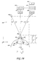
- FIG. 7B schematically illustrates an embodiment of an ophthalmic measurement system 500 for measuring dimensions of or in a patient's 502 eye using two lasers 508, 510 that do not cross at the cornea of the eye 502.
- the lasers 508, 510 emit beams of laser light 516, 518 that cross at a point 504 before the corneal surface of the eye 502.
- the beams of light 516, 518 strike the corneal surface of the eye at location 503 and location 505 respectively, propagate through the eye and strike the posterior surface of the aphakic capsular bag 506 at location 520 and location 522 respectively.
- At each of the locations 503, 505, 520, 522 a portion of the light is scattered by the cornea or capsular bag.
- a portion of the scattered light is collected by the optics 512 and directed to a detector 524.
- An image (such as the image 530 shown in FIG. 7A ) is formed on the detector 524 having two center spots 532, 533 and two target spots 534, 536.
- the detector 534 can be electronically coupled to a processor 526, which can be coupled to a suitable memory 538 and a user interface 542.
- the processor 526 can be configured to calculate the distance y 1 '" from the corneal surface to the posterior wall of the aphakic capsular bag 106 based in part on the data received from the detector 524.
- the processor 526 can be configured to calculate the distance x 2 "' between the locations 503, 505 where the laser beams 516, 518 intersect the cornea of the eye 502 based at least in part on the positions of the center spots 532, 533 in the image 530.
- the processor 526 can be configured to calculate the distance x 1 '" between the locations 520, 522 on the posterior surface of the aphakic capsular bag 506 based at least in part on the positions of the target spots 534, 536.
- the refraction of the beams of light 516, 518 as they enter the eye and propagate through the transitions within the eye can be ignored, so that the beams of light 516, 518 can be treated as though they propagate from the corneal surface to the posterior wall of the capsular bag 506 at the same non-zero angle ⁇ "' with respect to the optical axis 514.
- the distances y 3 "' and y 2 "' can be calculated using equations (5) and (6) provided below.
- Equation (4) can then be rewritten as equation (7) provided below. If the system 500 determines that the beams of laser light 516, 518 cross after passing through the corneal surface (as described above), the distance y 1 "' can be calculated using formula (8) provided below.
- an alignment system (e.g., 608 such as, for example, described herein) can also be used in determining the distances illustrated in FIG. 7B .
- the alignment system can be used to determine y 2 "'.
- the calculations disclosed herein can be altered to account for refraction of the beams of light 516, 518 as they enter the eye 502 and/or refraction as the light propagates through the various transitions within the eye 502.
- FIG. 8 schematically shows an embodiment of an ophthalmic apparatus 600 that includes a measurement system 606, an alignment system 608, and a wavefront aberrometer 610 mounted onto a surgical microscope 602.
- the apparatus 600 can include an auxiliary module 604 attached to the surgical microscope 602.
- the auxiliary module 604 can include the measurement system 606, as described herein, the alignment system 608, and the wavefront aberrometer 610.
- the measurement system 606 can be used, for example, for measuring anterior and/or posterior capsular bag depth or ACD.
- the alignment system 608 can be used for transversely and longitudinally positioning the ophthalmic apparatus 600 at a desired location with respect to the patient's eye, as described herein.
- the wavefront aberrometer 610 can be used, for example, to perform intraoperative refractive power measurements of the patient's eye.
- intraoperative measurements of the total refractive power of the patient's aphakic eye could be used in the calculation of IOL power in place of, or in addition to, preoperative corneal curvature and axial length measurements.
- the measurement system 606, alignment system 608, and wavefront aberrometer 610 are illustrated as a single module 604, other configurations are possible.
- the measurement system 606, alignment system 608, and wavefront aberrometer 610 can be arranged as two or three separate modules.
- the measurement system 606 and wavefront aberrometer 610 can be rigidly mechanically and/or optically coupled together (as described in more detail below).
- the alignment system 608 can also be rigidly mechanically coupled to the measurement system 606.
- the auxiliary module 604 can be removably attached to the surgical microscope 602 by one or more fasteners 616.
- FIG. 8 illustrates an x-y-z coordinate system similar to the coordinate systems of FIGS. 1 and 3 for reference.
- the y-axis is aligned with the visual axis of the patient's eye, with the x- and z-axes being mutually orthogonal to the y-axis.
- the alignment system 608 can be similar to the alignment system described in U.S. Patent Publication No. 2009/0103050 . Other types of alignment systems can also be used. As discussed above, in some embodiments, the measurement system 606 can be used to provide positioning information, and the measurement system 606 can be used in conjunction with, or in place of, the alignment system 608 for positioning the apparatus 600 with respect to the eye 612 of the patient 614.
- the wavefront aberrometer 610 can be, for example, a Talbot-Moire interferometer-type wavefront aberrometer, such as the wavefront aberrometer described in U.S. Patent No. 6,736,510 . It should be understood that other types of wavefront aberrometers may also be used. In some embodiments, the wavefront aberrometer 610 can be omitted, or a different ophthalmic instrument (e.g., a keratometer, corneal topographer, or Optical Coherence Tomography (OCT) system) can be used in addition to, or in its place of, the wavefront aberrometer 110, depending on the procedure to be performed.
- OCT Optical Coherence Tomography
- the surgical microscope 602 can be any suitable style or configuration known in the art, or yet to be devised.
- the auxiliary module 604, and especially the fasteners 616, can be configured to securely attach to a variety of surgical microscopes.
- the surgical microscope 602 can include an eyepiece 618, which can be binocular or monocular, that allows a surgeon to view a region of the eye 612.
- the surgical microscope 602 can also include a light source 620 for illuminating the patient's eye 612, a focusing knob 622 for adjusting the focus of the surgical microscope 602, and an objective lens 624 for collecting light from the patient's eye 612.
- the surgical microscope 602 is supported above the patient's eye by an adjustable boom.
- the measurement system 606 and/or the wavefront aberrometer 610 operates using light of non-visible wavelengths.
- the auxiliary module 604 can also include a wavelength selective mirror 626 that passes visible light to the objective lens 624 while reflecting light used by the measurement system 606 and/or the wavefront aberrometer 610, which may be, for example, in the near infrared range, to the measurement system 606 and/or the wavefront aberrometer 610 enclosed within the auxiliary module 604.
- the auxiliary module 604 can include additional optical components such as mirrors, lenses, beam splitters, filters, etc. for routing light to and among the components contained therein.
- FIG. 9 schematically illustrates an embodiment of the measurement system 606, the alignment system 608, and the wavefront aberrometer 610.
- FIG. 9 illustrates an x-y-z coordinate system similar to the coordinate systems described above for reference. It should be noted that FIG. 9 is a schematic illustration, and the layout illustrated thereby does not necessarily indicate the actual locations and directions used in the apparatus 600. For example, the optical paths are illustrated as being located in the x-y plane for simplicity, though some of the optical paths can be directed at least in part in the z direction.
- the wavefront aberrometer 610 includes a laser 628 that generates a thin beam of light having a planar wavefront which is directed by a first beam splitter 630 and a wavelength selective mirror 626 into the patient's eye 612.
- the laser light passes through the cornea and the pupil of the patient's eye and impinges on the retina.
- the laser light scatters from the retina and propagates back through the cornea of the eye 612 and toward the wavelength selective mirror 626.
- the altered wavefront is reflected by the wavelength selective mirror 626, passes through the first beam splitter 630, is reflected by a second beam splitter 632, passes through a first lens doublet 634, is re-directed by a first and second relay mirrors 636, 638, and passes through a second lens doublet 640.
- a pair of reticles, or gratings, 642, 644 is disposed between the second lens doublet 638 and the aberrometer detector 646.
- the aberrometer detector 646 can be a charge-coupled device (CCD), although other detectors may also be used.
- CCD charge-coupled device
- the reticles 642, 644 can generate fringe patterns on the aberrometer detector 646 which are detected and used to determine the shape of the altered wavefront in, for example, the manner described in U.S. Pat. No. 6,736,510 .
- the shape of the alternate wavefront can then be used to determine, for example, the spherical power, cylindrical power, and cylindrical axis of the patient's eye.
- the measurement system 606 can include one or more lasers 648, only one of which is shown for simplicity, oriented to direct light into the eye as described above.
- the lasers 648 can be rigidly attached to the outside of a housing associated with the auxiliary module 604, or inside the housing such that the laser light is directed through openings in the housing toward the patient's eye 612.
- the lasers 648 can be attached having fixed angles.
- the laser light can enter the eye through the corneal surface 650 of the eye 612 and impinge upon the target surface 652 (e.g., the posterior wall of the capsular bag).
- the target surface 652 e.g., the posterior wall of the capsular bag.
- Light can be scattered by both the corneal surface 650 and the target surface 652 within the eye 612.
- the scattered light is reflected by the wavelength selective mirror 626, passes through the first beam splitter 630 and the second beam splitter 632, passes through a third lens doublet 654, gets redirected by two mirrors 656, 658, and passes through a fourth lens doublet 660 toward a measurement system detector 662.
- the light received by the detector 662 can be used to determine the distance between the corneal surface 650 and the target surface 652 within the eye 612.
- an optical axis 676 of the apparatus is defined by the optics of the measurement system 606 and/or wavefront aberrometer 610.
- the measurement system 606 and the wavefront aberrometer 610 are designed to operate at a common working distance so that they both can collect accurate data when the apparatus 600 is properly aligned at a desired transverse and longitudinal position.
- the lasers 648 of the measurement system 606 can use the same wavelength (e.g., 780 nm) of light as the laser 628 of the wavefront aberrometer 610.
- the wavelength selective mirror 626 can be used to direct light from both the wavefront aberrometer 610 and the measurement system 606 toward the second beam splitter 632.
- the measurements performed by the measurement system 606 and the wavefront aberrometer 610 can be performed at different times so that light from one system does not affect the measurements taken by the other.
- the lasers 648 can use a different wavelength of light than the laser 628, so that measurements can be taken using the measurement system 606 at the same time that measurements are taken using the wavefront aberrometer 610, resulting in less waiting time during the surgical procedure.
- wavelength selective mirror 626 can be configured to direct light of both wavelengths to the second beam splitter 632.
- the apparatus 600 can use one or more wavelength selective mirrors to route light of one wavelength to the aberrometer detector 646 and light of another wavelength to the measurement system detector 662.
- the alignment system 608 can include one or more light sources, such as light emitting diodes (LEDs) 664, 666.
- the LEDs 664, 666 can be positioned, for example, about the optical axis 676 of the apparatus and near the input window 668 of the wavefront aberrometer 610.
- the LEDs 664, 666 use a different wavelength of light than the lasers 648, 628.
- the LEDs can use light having a wavelength of 880 nm, although light of other wavelengths may also be used.
- the alignment system 608 also includes an alignment camera having alignment optics 670 and an alignment detector 672.
- the alignment optics 670 can define an alignment optical axis 674, which intersects the cornea of the eye 612.
- the alignment optical axis 674 intersects the optical axis defined by the optics of the measurement system 606 and/or the wavefront aberrometer 610 at the corneal surface of the eye when the apparatus 600 is positioned at the desired location with respect to the patient's eye 612.
- Light emitted from the LEDs 664, 666 propagates toward the cornea of the eye 612 and a portion of the light is reflected by the cornea generally along the alignment optical axis 674 so that it passes through the alignment optics 670 which creates an image of the LEDs 664, 666 on the alignment detector 672, which can be, for example, a CCD sensor.
- the positioning of the images of the LEDs 664, 666 will, in general, depend upon the spatial positioning of the apparatus 600 and the corneal curvature of the patient's eye.
- a reference location can be defined on the detector 672 based on the corneal curvature of the patient's eye 612 and the desired position of the apparatus 600 with respect to the eye 612.
- the alignment system 608 can provide alignment information for positioning the apparatus 600 at the desired location relative to the eye 612, as described in more detail in U.S. Patent Publication No. 2009/0103050 .
- the positioning system 608 can position the apparatus 600 to within 1 mm, 500 ⁇ m, 300 ⁇ m, or 150 ⁇ m of the desired location relative to the patient's eye 612.
- the apparatus 600 includes a processor 676, which can be in electronic communication with the measurement system detector 662, the aberrometer detector 646, and the alignment detector 672.
- the processor can also be in electronic communication with a memory module 678 as discussed above, as well as a video monitor 680 or other display device for conveying information to the user.
- the processor 676 can receive and process data from the detectors 646, 662, 672 as described herein.
- the processor 676 can use data from more than one of the detectors 656, 662, 672 to perform a function, such as produce positioning information.
- data from the measurement system 606 can be used in conjunction with the alignment system 608 to produce positioning information.
- the apparatus 600 can include actuators (not shown) for automatically adjusting the position of the apparatus 600 based on the positioning information.
- the apparatus 600 can also include controls (not shown) that allow the user to adjust the position of the apparatus 600 according to the positioning information provided, for example, via the video monitor 680.
- the ophthalmic measurement system 606 and the wavefront aberrometer 610 can use the same detector.
- FIG. 10 schematically illustrates an embodiment of the optics system 700 of an ophthalmic measurement system (e.g., 100, 200, 606) for collecting light scattered by the eye 752 from both the ophthalmic measurement system 606 and the wavefront aberrometer 610 and directing the light to a shared detector 762. A portion of the scattered light is reflected by a wavelength-selective mirror 726 (626 in FIG. 8 ) to a beam splitter 730, which transmits a portion of the scattered light toward a first lens 754.
- an ophthalmic measurement system e.g., 100, 200, 606
- the wavelength-selective mirror 726 can be used, for example as described herein, to transmit visible light to a surgical microscope while reflecting infrared light used by the measurement system 606 and wavefront aberrometer 610.
- the beam splitter 730 can be used, for example as described herein, to direct a portion of a beam of laser light from a laser (628 in FIG. 8 ) to the eye 752 for use by the wave front aberrometer 610.
- the first lens 754 can be a lens doublet and can operate with optical power on the scattered light.
- the lens 754 can act to converge the scattered light, and direct it to a first mirror 756, which reflects the light to a second mirror 758.
- the second mirror 758 can direct the scattered light through a spatial aperture 759 to a second lens 760, which can be a doublet lens and can operate with optical power on the scattered light.
- the lens 760 can act to further converge the scattered light to form a real image on the detector 762.
- the optical system 700 can include a pair of gratings (not shown in FIG. 10 ) positioned between the lens 760 and the shared detector 762.
- the positions of the optical elements of the optical system 700 are fixed.
- some of the optical elements of the system 700 can be movable.
- the lens 760 and/or the lens 754 can be movable so as to adjust the effective focal length of the optics system 700 depending on the measurement being taken (e.g., posterior or anterior aphakic capsular bag depth or ACD), the characteristics of the eye being measured (e.g., phakic or aphakic), whether the measurement system 606 or the wavefront aberrometer 610 is being used, etc.
- the optics system 700 can be configured to form a sharp, focused image on the detector 762 for a variety of applications.
- the gratings can be movable so that they can be placed in the optical path when the wavefront aberrometer is in use and removed from the optical path when the measurement system 606 is in use. In some embodiments, the gratings can remain in the optical path when the measurement system 606 is in use.
- FIG. 10 contains an x-y-z coordinate system in which the y-axis is aligned with the visual axis of the eye and the x- and z-axes are mutually orthogonal to the y-axis.
- Other coordinate systems can be used, and the optical elements illustrated in FIG. 10 can be oriented in directions other than that shown in FIG. 10 .
- FIG. 11 schematically illustrates light from the ophthalmic apparatus of FIG. 8 interacting with an optical model of a patient's eye 800 during a measurement process.
- FIG. 11 contains an x-y-z coordinate system in which the y-axis is aligned with the visual axis of the eye and the x- and z-axes are mutually orthogonal to the y-axis. Other coordinate systems can be used.
- a first beam of laser light 802 contacts the cornea 804 of the eye 800 at the corneal surface 806. A portion of the light 802 is scattered at the corneal surface, shown in FIG. 11 as dotted lines 807.
- the first beam of laser light 802 passes through various structures of the eye, including the cornea 804, the aqueous humor 808, etc.
- the first beam of laser light 802 can be refracted as it enters the eye 800 and propagates through the various structures of the eye.
- the first beam of laser light 802 eventually impinges on the posterior wall of the capsular bag 810, where part of the light 802 is scattered (shown as dashed lines 812) and part of the light 802 passes through the capsular bag and propagates further into the eye 800.
- the scattered light 812 can be refracted by the various transitions within the eye and can also be refracted as it exits the eye 800.
- the ray trace shown in FIG. 11 is a simplified ray trace, showing relatively few rays of light for simplicity.
- the beams of laser light e.g., 802
- the beams of laser light are shown as a single ray, when during actual operation the beams of laser light can have a perceptible thickness.
- a second beam of laser light 814 can enter the eye 800 through the corneal surface 806.
- a portion of the second beam of laser light 814 is also scattered by the corneal surface 806 (the scattered light is shown in FIG. 11 by dotted lines 807).
- the second beam of laser light 814 can be refracted similarly to the first beam of light 802 discussed above, as it enters the eye 800 and propagates to the posterior wall of the capsular bag 810.
- a portion of the second beam of light 814 can be scattered by the capsular bag 810 (the scattered light is shown in FIG. 11 as dashed lines 816).
- the scattered light 816 can be refracted as it propagates through the transitions within the eye 800 and as it exits the eye 800.
- the scattered light 807, 812, 816 can be directed to a detector and used to determine the distance from the corneal surface 806 to the posterior wall of the capsular bag 810, as discussed herein.
- a third beam of laser light 818 can be directed into the eye 800 through the corneal surface 806 so that it propagates to the retina (not shown) and is scattered by the retina.
- the third beam of laser light 818 correspond to the probe beam of the wavefront aberrometer 610, as described herein.
- the scattered light from the retina can be used by the wavefront aberrometer 610 to measure the optical power of the eye.
- FIG. 12 is a flowchart showing an embodiment of a method 900 for determining appropriate optical power for an IOL to be implanted into a patient's eye as part of a cataract surgery.
- the user can position the ophthalmic apparatus 600 at a predetermined desired position over the eye of the patient.
- the desired position can place the apparatus laterally so that an optical axis of the measurement system substantially aligns with the visual axis of the eye, and longitudinally so that the lasers of the measurement system intersect at the corneal surface of the eye.
- the user can use the surgical microscope to coarsely position the apparatus 600. During some applications, it may be desirable to fine tune the position of the apparatus 600 using the alignment system 608, as described herein.
- the alignment system 608 can be used in conjunction with the wavefront aberrometer 610 and/or the spatial measurement system (e.g., 100, 200, 606) to generate positioning information.
- the positioning of the apparatus may be performed automatically using a processor and actuators, or manual using controls provided to the user.
- a different ophthalmic apparatus can be used.
- an ultrasound (not according to the invention) or optical coherence tomography measurement device can be used.
- the ultrasound (not according to the invention) or optical coherence tomography device can be mounted onto the surgical microscope or onto the aberrometer, but space restrictions may limit the type of measurement device mounted thereto.
- the apparatus may be positioned differently with respect to the patient's eye depending on the type measuring device used.
- the apparatus 600 can be used to measure at least one intraoperative characteristic of the eye, such as the posterior capsular bag depth of the aphakic eye.
- the additional step of removing the natural crystalline lens from the eye can be performed beforehand, converting the eye into an aphakic eye.
- the globe and capsular bag can be inflated (e.g., with basic saline solution or a visco-elastic material) after the natural crystalline lens is removed.
- an ophthalmic measurement system e.g., 100, 200, 606) as described herein can be used to measure the posterior capsular bag depth.
- Light from one or more lasers can be directed into the eye through the corneal surface so that light from the lasers is scattered by the corneal surface and also scattered by the capsular bag within the eye.
- the scattered light can be collected and directed to a detector where spots are formed corresponding to the locations from which the light was scattered.
- a processor can be configured to determine the posterior capsular bag depth of the aphakic eye based at least in part on the positions of the spots formed on the detector, as described herein.
- the posterior capsular bag depth can be measured using ultrasound technology (not according to the invention) or optical coherence tomography.
- anterior aphakic capsular bag depth can be measured. This distance can be used, for example, to predict the postoperative position of an IOL to be placed anterior of the capsular bag (e.g., a sulcus lens) rather than inside the capsular bag itself. This distance can also be used instead of, or in conjunction with, the posterior aphakic capsular bag depth to predict the postoperative position of an IOL in the capsular bag. Other intraoperative characteristics of the eye can also be measured.
- the apparatus 600 can be used to measure the optical power of the aphakic eye.
- a wavefront aberrometer 610 can be used to measure the optical power of the aphakic eye, as described herein.
- the optical power of the aphakic eye can be determined by other methods.
- the optical power of the aphakic eye can be estimated from the curvature of the cornea and the axial length of the eye.
- a predicted post operative IOL position can be calculated based at least in part on the measured at least one intraoperative characteristic of the eye (e.g., the aphakic capsular bag depth of the eye).
- the predicted post operative position of the IOL can be determined based on the measured posterior aphakic capsular bag depth without the use of additional measurements of the eye.
- the ELP for the IOL can be determined by subtracting a constant from the measured posterior aphakic capsular bag depth.
- the measured optical power of the aphakic eye or other factors can also be considered to predict the post operative IOL position, such as the curvature of the cornea, the axial length of the eye, etc.
- the correlation between aphakic capsular bag depth and the postoperative IOL position can be established by measuring the actual postoperative IOL position for patients for which the aphakic capsular bag depth was measured, and, after a sufficient sampling, a statistical regression algorithm or the like can be used to generate a relationship between the aphakic capsular bag depth and postoperative IOL position.
- the postoperative position of an IOL inside the capsular bag can be predicted.
- the postoperative position of an IOL at other locations (e.g., for a sulcus lens) can also be predicted.
- the power for the IOL to be implanted into the patient's eye can be calculated using, at least in part, the predicted postoperative IOL position. Other factors can also be considered, such as the optical power of the aphakic eye, the axial length of the eye, etc. By accurately estimating the postoperative IOL position, an appropriate power for the IOL can be selected more accurately, yielding superior surgical results that can be more effective at restoring a patient's eye to an emmetropic condition.
- Software modules can comprise computer executable code for performing the functions described herein.
- computer-executable code is executed by one or more general purpose computers.
- any module that can be implemented using software to be executed on a general purpose computer can also be implemented using a different combination of hardware, software, or firmware.
- such a module can be implemented completely in hardware using a combination of integrated circuits.
- such a module can be implemented completely or partially using specialized computers designed to perform the particular functions described herein rather than by general purpose computers.
Description
- Embodiments of the invention relate generally to systems for performing ophthalmic measurements. In particular, some embodiments can be used for measuring a spatial distance in a patient's eye such as, for example, the distance between the corneal surface and the posterior wall of the capsular bag in an aphakic eye.
- Various ophthalmic procedures involve measurements of a spatial distance within a patient's eye, including measurements of the dimensions of the eye, or dimensions of features of the eye, the distance between selected portions or features of the eye, etc. For example, such measurements can be of the anterior chamber depth (ACD), lens thickness, and axial length of the eye. Techniques for making certain types of these measurements include ultrasonic measuring and Optical Coherence Tomography (OCT). Despite the successes of these techniques in various ophthalmic applications, there is a continuing need for improved techniques and systems for measuring spatial distances within the eye.
- U.S. patent
US 4,019,813 A discloses an optical apparatus for obtaining one or more measurements of portions of an eye having means for providing a narrow beam of light through the eye, a lens system that collects light that is reflected from the eye and forms an image on the surface of a television camera tube, and means for determining when the narrow beam of light passes through the center of curvature of the cornea and when the instrument is correctly positioned for proper focus on the eye. - Various embodiments disclosed herein include an ophthalmic apparatus. The ophthalmic apparatus can include a first laser configured to direct a first beam of light into an eye of a patient at a first non-zero angle with respect to an optical axis of the apparatus, such that the first beam of light propagates to a target area within the eye, and such that a portion of the first beam of light is scattered by the target area. The apparatus can also include imaging optics positioned to receive light scattered by the target area, and the imaging optics can define the optical axis of the apparatus. The apparatus can also include a photosensitive element, wherein the imaging optics direct the light scattered from the target area to the photosensitive element. The apparatus can also include a processor configured to determine a distance between the cornea of the eye and the target area within the eye based at least in part on the light received by the photosensitive element.
- Various embodiments disclosed herein include a method of determining the optical power for an intraocular lens to be implanted into an eye. The method can include measuring an intraoperative characteristic of the eye. The intraoperative characteristic can include the distance between selected first and second portions of the eye. The method can also include determining the optical power for the intraocular lens based at least in part on the measured intraoperative characteristic.
- Various embodiments disclosed herein include a method of using an ophthalmic apparatus. The method can include positioning the ophthalmic apparatus at a predetermined position over an eye of a patient, wherein an optical axis of the apparatus intersects the cornea of the eye. The method can include directing light from one or more lasers positioned about the optical axis of the apparatus into the eye so that a portion of the light from the one or more lasers is scattered by a target area inside the eye. The method can include directing a portion of the light scattered by the target area to a photosensitive element using imaging optics that define the optical axis. The method can include forming one or more target spots on the photosensitive element, and the one or more target spots can correspond to the light from the respective one or more lasers scattered by the target area. The method can also include calculating the distance between the cornea of the eye and the target area based at least in part on the positions of the one or more target spots. A device according to the invention is defined in claim 1.
-
-
FIG. 1 schematically illustrates an embodiment of an ophthalmic measurement system for measuring dimensions of or in a patient's eye including, for example, the distance between the cornea and a posterior wall of the capsular bag in an aphakic eye. -
FIG. 2 is an example image produced by the ophthalmic measurement system ofFIG. 1 . -
FIG. 3 schematically illustrates an embodiment of an ophthalmic measurement system for measuring dimensions of or in a patient's eye including, for example, the distance between the cornea and the anterior surface of the crystalline lens in a phakic eye. -
FIG. 4 is an example image produced by the ophthalmic measurement system ofFIG. 3 . -
FIG. 5 is an example image produced by an ophthalmic measurement system similar to those ofFIGS. 1 and3 but with a single laser. -
FIG. 6 is an example image produced by an ophthalmic measurement system similar to those ofFIGS. 1 and3 but with four lasers. -
FIG. 7A is an example image produced by an ophthalmic measurement system similar to those ofFIGS. 1 and3 but when two lasers are oriented to produce laser light beams that do not intersect at the corneal surface of the eye. -
FIG. 7B schematically illustrates an embodiment of an ophthalmic measurement system for measuring dimensions of or in a patient's eye using two lasers that do not cross at the cornea of the eye. -
FIG. 8 schematically illustrates an embodiment of an ophthalmic apparatus that includes an alignment system and a measuring system mounted onto a surgical microscope. -
FIG. 9 schematically illustrates an embodiment of a wavefront aberrometer, a measurement system, and an alignment system for positioning the wavefront aberrometer and measurement system at a desired location relative to the patient's eye. -
FIG. 10 schematically illustrates an embodiment of optics for use in an ophthalmic measurement system, the optics collecting light scattered by the patient's eye and directing the light to a detector. -
FIG. 11 schematically illustrates light from the ophthalmic apparatus ofFIG. 8 interacting with an optical model of a patient's eye during a measurement process. -
FIG. 12 is a flowchart showing an example embodiment of a method for determining the power for an intraocular lens (IOL) for insertion in a given patient's eye. - In a typical intraocular lens (IOL) implantation surgery, a surgeon removes the natural crystalline lens from a patient's eye and an IOL is implanted in its place. IOL implantation surgery can be performed, for example, on a patient suffering from cataracts. By selecting an IOL having an appropriate power, an eye that prior to the surgery was, for example, myopic (near sighted), hyperopic (far sighted), and/or astigmatic can be restored to an emmetropic condition. Various factors can be considered when calculating the appropriate power for the IOL, such as 1) the axial length of the eye, measured from the corneal surface to the retina; 2) the total optical power of the cornea; 3) the desired postoperative optical power (e.g., 0.0 diopters (D) for an emmetropic eye); and the effective lens position (ELP) of the IOL, which can be understood, for example, as the distance from the corneal surface to the post-operative position of the IOL. The axial length of the eye can be measured preoperatively (e.g., before the patient has been located on the operating table in a supine position), for example, by an ultrasound device or by Optical Coherence Tomography (OCT). The optical power of the cornea can be estimated from the corneal curvature values (Ks) of the eye measured preoperatively by a keratometer. Alternatively, or in addition, the total refractive power of the aphakic eye, which is a function of corneal curvature and axial length of the eye, can be measured intraoperatively and used in the IOL power calculation.
- The ELP of the IOL has traditionally been difficult to determine. The ELP of the IOL can be estimated based on preoperative data, but such estimates are limited in their accuracy. The limited accuracy of ELP estimates based on preoperative data can be attributed, at least in part, to the implanted IOL being positioned in the capsular bag differently than the natural crystalline lens. Preoperative measurements of the crystalline lens position do not always correlate well with the actual postoperative position of the IOL. Cataractous crystalline lenses vary in shape and size from individual to individual. In some patients, preoperative measurements (e.g., the ACD, which can be understood as, for example, the distance from the corneal surface to the anterior lens surface plus half the lens thickness) may provide a reasonable estimate of the ELP, but in other patients this is not the case due to the differing shapes of cataractous lenses in patients.
- Some efforts have been made to develop formulas to estimate the ELP of the IOL based on preoperative information, such as direct measurements of the axial length and corneal curvature of the patient's eye. Such formulas include the Holladay 1, SRK/T, Hoffer Q, Holladay 2, and Hagis formulas. Generally speaking, these formulas are based on statistical regression analysis of the relationship between pre-operative characteristics of the eye and the surgical outcome. These formulas sometimes produce estimates of the ELP of the IOL with insufficient accuracy, especially in those patients with axial lengths outside the normal range, resulting in suboptimal surgical results, for example, wherein the patient's eye is not restored to an emmetropic condition. These formulas all attempt to determine how an individual patient may vary from the average of a large population to estimate the ELP. The factors used by these formulas to estimate the ELP for a particular patient are not factors that directly relate to the lens position.
- Given the sometimes-insufficient level of correlation between estimates of the ELP for an IOL and characteristics of the eye that can be measured preoperatively (e.g., corneal curvature, axial length, etc.), it would be desirable to estimate the ELP for the IOL based on characteristics of the eye that are more closely correlated with ELP, such as certain intraoperative characteristics of the eye. One such intraoperative characteristic of the eye is the location of the aphakic capsular bag within the eye (e.g., the longitudinal distance from the anterior corneal apex to the posterior wall of the aphakic capsular bag). The location of the aphakic capsular bag is an example of an intraoperative characteristic of the eye that is believed to be more closely correlated with the ELP of the IOL than are the preoperative characteristics of the eye from which the Holladay 1, SRK/T, Hoffer Q, Holladay 2, and Hagis formulas estimate the ELP of the IOL. This is at least in part due to the fact that an aphakic measurement of the distance from the cornea to the posterior wall of the capsular bag is not tainted by the irregular size and shape of the caratactous lens. Regression analysis can be used to establish the correlation between the location of the aphakic capsular bag and the postoperative position of the IOL. Because the location of the aphakic capsular bag is believed to be closely correlated with the ELP, measuring the location of the aphakic capsular bag can reduce the complexity of ELP calculations. For example, in some embodiments, the ELP can be calculated by subtracting a constant from the measured distance from the cornea to the posterior wall of the aphakic capsular bag, wherein the constant is determined by the -regression analysis of postoperative IOL lens position or other outcome analysis. Various other formulas can be used to calculate the ELP.
- According to the invention, an ophthalmic apparatus is provided to perform intraoperative measurements of spatial distances of/within a patient's eye. These intraoperative measurements are measurements of the patient's aphakic eye. These intraoperative measurements are used to calculate an improved estimate of the ELP of the IOL, the improved estimate being a result of closer correlation between the intraoperative measurement and the ELP of the IOL than the correlation between preoperative measurements and the ELP of the IOL. The ophthalmic apparatus measures a distance between the cornea and the aphakic capsular bag. This distance is between a selected position or portion of the cornea and a selected position or portion of the aphakic capsular bag. The selected portion of the cornea can be, for example, the location on the corneal surface where the visual axis of the eye intersects the corneal surface and/or the location where the corneal surface is perpendicular to the visual axis. The selected portion of the cornea can be other locations as well, such as the corneal apex. The selected portion of the capsular bag can be, for example, all or a portion of its posterior wall, all or a portion of its anterior wall, etc.
- In some embodiments, the ophthalmic apparatus measures the aphakic capsular bag depth which can be understood, for example, as the distance from the cornea of the eye to the posterior or anterior surface of the capsular bag in an aphakic eye. An aphakic eye is an eye in which the lens of the eye is absent, while a phakic eye has the natural crystalline lens contained therein. The ophthalmic apparatus can be used during an IOL implantation surgery after the natural crystalline lens has been removed from the eye. The measured aphakic capsular bag depth can be used to predict the postoperative position of the IOL with greater accuracy than traditional methods, allowing the surgeon to more accurately calculate the appropriate power for the IOL to be implanted during the surgical procedure. In some embodiments, the actual IOL postoperative position can be measured after the IOL has been implanted (e.g., using OCT or an ultrasound device), and that data can be used to improve the correlation between aphakic capsular bag depth and postoperative IOL position.
-
FIG. 1 schematically illustrates an embodiment of anophthalmic measurement system 100 for measuring dimensions of or in a patient'seye 102. InFIG. 1 , theophthalmic measurement system 100 is shown configured to measure the distance y1 between thecorneal surface 104 of theeye 102 and the posterior wall of thecapsular bag 106. According to the invention, the eye is aphakic, the natural crystalline lens having been removed from the eye beforehand, such as during an IOL implantation surgery procedure. This measurement can be performed, for example, intra-operatively before or after the globe and capsular bag have been inflated (e.g., with basic saline solution or visco-elastic material). - For convenience, a three-dimensional coordinate system can be defined having a y-axis parallel to the visual axis of the patient's
eye 102, and x- and z-axes that are mutually orthogonal to the y-axis so that the x- and z-axes define a plane that is perpendicular to the visual axis of the eye. In the context of this three-dimensional coordinate system, lateral positioning of theophthalmic measurement system 100 corresponds to the x and z coordinates of theophthalmic measurement system 100, while longitudinal positioning corresponds to the y coordinate of theophthalmic measurement system 100. It should be understood that the coordinate system described is for illustrative purposes only and other coordinate systems and other configurations can be used. For example, in some embodiments, the y-axis can be parallel with the optical axis of the patient'seye 102 and the x- and z-axes can define a plane that is perpendicular to the optical axis of the patient'seye 102. - The
ophthalmic measurement system 100 can includeoptics system 112 for collecting, directing, and/or focusing light that is scattered by theeye 102 during a measurement process. Theoptics system 112 can define anoptical axis 114 of theophthalmic measurement system 100. In some embodiments, theophthalmic measurement system 100 can be positioned at a predetermined position relative to the patient'seye 102. For example, theophthalmic measurement system 100 can be positioned laterally so it is centered over the pupil of the eye, and/or so that theoptical axis 114 is substantially collinear with the visual or optical axis of theeye 102. Theophthalmic measurement system 100 can be positioned longitudinally so that it is located at a predetermined distance from theeye 102. As discussed in greater detail below, theophthalmic measurement system 100 can be used in conjunction with a positioning system (not shown inFIG. 1 ) for accurately positioning theophthalmic measurement system 100 at the desired position. - The
ophthalmic measurement system 100 can include a pair oflasers lasers lasers lasers optical axis 114, and can be separated by a distance x2. In some configurations thelasers optical axis 114 is located substantially at a midpoint between thelasers lasers - In some embodiments, when positioned at the desired location with respect to the
eye 102, thelasers lasers corneal surface 104, although distances outside this range can also be used. In an example embodiment, thelasers corneal surface 104 of theeye 102. In some embodiments, thelasers eye 102. In other embodiments, one laser (e.g., 108) is positioned closer to theeye 102 than the other laser (e.g., 110). - In some embodiments, the
lasers beams 116, 118 are coplanar. Thelasers laser 108 is directed along a path that intersects thecorneal surface 104 of theeye 102 at the location where the visual axis of the eye intersects thecorneal surface 104, and so that the beam oflight 118 emitted by thelaser 110 is directed along a path that intersects the cornea of the eye at the corneal location where the visual axis of the eye intersects thecorneal surface 104. Thus, the beams oflight 116, 118 emitted by thelasers corneal surface 104 of theeye 102. Thelasers light 116, 118 at a non-zero angle θ with respect to theoptical axis 114. In some embodiments, the beams oflight 116, 118 deviate from theoptical axis 114 by an angle of at least about 13° and/or less than about 17°, although angles outside this range may also be used. In some embodiments, the beams oflight 116, 118 emitted by thelasers optical axis 114 by substantially the same amount, but in substantially opposite directions, though the angle between each beam and theoptical axis 114 need not be identical. In some embodiments, the angles by which the beams oflight 116, 118 deviate from the optical axis are within 10°, 5°, 3°, 2°, 1 °, or less of each other. - As the beams of
light 116, 118 enter theeye 102 at thecorneal surface 104, a portion of the light is scattered by thecorneal surface 104, and a portion of the light propagates through the cornea and into theeye 102. The beam of light 116 strikes the posterior wall of thecapsular bag 106 at afirst location 120, and a portion of the beam of light 116 is scattered by the posterior wall of thecapsular bag 106. Similarly, the beam oflight 118 strikes the posterior wall of thecapsular bag 106 at asecond location 122, and a portion of the second beam oflight 118 is scattered by the posterior wall of thecapsular bag 106. - The
optics system 112 can collect a portion of the scattered light and can direct the collected light to adetector 124. In some embodiments, theoptics system 112 is configured to focus the scattered light onto thedetector 124. Theoptics system 112 can form an image on thedetector 124. In some embodiments, theoptics system 112 is designed such that thedetector 124 and the posterior wall of thecapsular bag 106 are located at conjugate planes. As will be discussed in more detail below, theoptics system 112 can include various optical elements, such as mirrors, lenses, filters, apertures, and beam splitters. It should be understood that theoptical axis 114 is not necessarily a straight line along the entire optical path within theophthalmic measurement system 100 as it may be bent by various optical elements within theoptics system 112. Thedetector 124 can comprise a charge-coupled device (CCD) or other type of photosensitive element. In some embodiments, thedetector 124 includes a two-dimensional array of light-sensitive pixels configured to generate an electric signal that is descriptive of the light that strikes the pixels. For example, a CCD sensor measuring 16 mm by 16 mm and having a two-dimensional array of 500 by 500 pixels can be used, although other configurations are also possible. - The
detector 124 can provide the electric signal to aprocessor 126. Theprocessor 126 can be configured to process the data received from thedetector 124 as described herein. In some embodiments, theprocessor 126 can be in electronic communication with asuitable memory 128 for storing accumulated data, instructions to be executed by theprocessor 126, parameters relating to the patient'seye 102, or other data. Theprocessor 126 can also be in electronic communication with auser interface 142 to allow the user to input information regarding the patient's eye (e.g., aphakic or phakic), information regarding the distance to be measured, or other information. -
FIG. 2 shows anexample image 130 that can be formed on thedetector 124 during a measurement process.FIG. 2 includes a coordinate system similar to the coordinate system shown inFIG. 1 . AlthoughFIG. 2 shows theimage 130 as being formed on thedetector 124 in the x-z plane, thedetector 124 can be oriented differently. Theimage 130 can include acenter spot 132 corresponding to the light scattered at thecorneal surface 104, afirst target spot 134 corresponding to the light of the beam 116 scattered by thefirst location 120, and asecond target spot 136 corresponding to the light of thebeam 118 scattered by thesecond location 122. In some embodiments, theoptics system 112 can be configured so as to provide a depth of field that is large enough so that thecenter spot 132 and both of the target spots 134, 136 are in focus so as to provide sharp focused spots on thedetector 124. In some embodiments, the optics system can be configured so that one or more of thespots spots center spot 132 can be appreciably out of focus while the target spots 134, 136 are in focus. Theprocessor 126 can be configured to analyze the data received from thedetector 124 and to determine therefrom a measurement of the distance y1, for example. In some embodiments, this analysis may include locating the centroid of one or more of thespots spots - The
processor 126 is configured to calculate the distance y1 from thecorneal surface 104 to the posterior wall of thecapsular bag 106 based at least in part on the data received from thedetector 124. Theprocessor 126 can calculate the distance x1 between thelocations image 130. For example, theprocessor 126 can determine the number of pixels between the locations of the target spots 134, 136 and apply an algorithm that calculates the real-world distance between thelocations optics system 112. In some embodiments, any refraction of the beams oflight 116, 118 as they enter the eye and as they pass through the various optical transitions within the eye can be ignored, so that each of the beams oflight 116, 118 can be treated as though it propagates from thecorneal surface 104 to the posterior wall of thecapsular bag 106 at the same non-zero angle θ with respect to theoptical axis 114. In this embodiment, the distance y1 can be calculated using equation (1) provided below.
(1) - In some embodiments, the angle θ is not known, but the distance x2 of separation between the
lasers corneal surface 104 are known. The distance y1 can be calculated using equation (2) provided below.
(2) - In some embodiments, the calculations for determining the distance y1 can be adjusted to account for refraction of the beams of light as they enter the eye and/or as they propagate through the various refractive index transitions within the eye.
- Although some embodiments discussed above describe the measurement of the posterior capsular bag depth in an aphakic eye, some embodiments can be used to measure other dimensions or spatial relationships of or in the patient's eye, such as, for example, the anterior chamber depth (ACD), which can be understood, for example, as the distance from the cornea to the anterior surface of the crystalline lens in a phakic eye. This distance can be between a selected position or portion of the cornea and a selected position or portion of the natural crystalline lens. The selected portion of the cornea can be, for example, the location on the corneal surface that intersects the visual axis of the eye. The selected portion of the crystalline lens can be, for example, all or a portion of its anterior surface of the lens, etc. The portion of the anterior surface can be, for example, the most anterior portion of the anterior surface, the position where the visual axis or the optical axis of the eye intersects the anterior surface, etc.
-
FIG 3 schematically shows an embodiment of anophthalmic measurement system 200 for measuring dimensions of or in a patient's eye including, for example, the anterior chamber depth (ACD) in aphakic eye 202. Theophthalmic measurement system 200 can be similar in some ways to theophthalmic measurement system 100 discussed above, some of the disclosure of which applies also theophthalmic measurement system 200, though some differences are identified below. Accordingly, in some embodiments, for example, theophthalmic measurement system 200 can be the sameophthalmic measurement system 100 used to measure the posterior capsular bag depth in an aphakic eye (as shown inFIG. 1 ), with or without modifications in configuration. - The
ophthalmic measurement system 200 can includelasers light eye 202 of the patient through thecorneal surface 204. The beams oflight corneal surface 204 where a portion of the light from each of thebeams corneal surface 204. The first beam oflight 216 can propagate to afirst location 220 on the anterior surface of thecrystalline lens 206, which scatters a portion of light. Similarly, the second beam oflight 218 can propagate to asecond location 222 on the anterior surface of thecrystalline lens 206, which scatters a portion of the light. A portion of the light scattered by thecorneal surface 204 and the first andsecond locations optics system 212 and directed to thedetector 224. In some embodiments, theoptics system 212 ordetector 224 can be especially configured for use with light reflected from thecrystalline lens 206. For example, theoptics system 212 can be configured to focus light differently than theoptics system 112 used to measure the posterior capsular bag depth in an aphakic eye to accommodate for the different object distance. In some embodiments, thesame optics system 112 anddetector 124 can be used to measure the posterior capsular bag depth in an aphakic eye as well as the ACD in a phakic eye with or without the need for adjustments. -
FIG. 4 shows anexample image 230 formed on thedetector 224 during a measurement process.FIG. 4 includes a coordinate system similar to the coordinate system shown inFIG. 2 . Theimage 230 includes acenter spot 232 corresponding to the light scattered at thecorneal surface 204, afirst target spot 234 corresponding to the light scattered by thefirst location 220 on thecrystalline lens 206, and asecond target spot 236 corresponding to the light scattered by thesecond location 222 on thecrystalline lens 206. Theprocessor 226 can be configured to calculate the distance y1' based on the locations of thespots image 230 is shorter than the distance y1 being measured by theimage 130. - Other distances within the patient's eye can similarly be measured. For example, the anterior aphakic capsular bag depth can be measured. This distance can be understood as, for example, the distance between the corneal surface and the anterior surface of the aphakic capsular bag. This measurement can be performed, for example, intra-operatively after the natural crystalline lens has been removed but before or after the globe and capsular bag have been inflated (e.g., with basic saline solution or visco-elastic material). This distance can be used, for example, separately from, or in conjunction with, the posterior aphakic capsular bag depth for calculating the ELP for an IOL. For example, in the case of an IOL that is inserted in the capsular bag, the estimated ELP can be selected to be some fraction of the way between these two distances. Other relationships relating these two distances to the estimated ELP of an IOL in the capsular bag are also possible and can be determined by, for example, regression analysis, as described herein. In addition, the anterior capsular bag depth measurement can be used for calculating the predicted position of a sulcus lens. For example, the estimated ELP of a sulcus lens could be related to the distance from the corneal surface to the anterior surface of the capsular bag by subtracting an empirically-derived constant from the measured distance. Other relationships relating this distance to the estimated ELP of a sulcus lens are also possible and can be determined by, for example, regression analysis, as described herein.
- Also, the distance between the
corneal surface 204 and the posterior wall of the capsular bag can be measured in thephakic eye 202 using light scattered bylocations light image 230 formed on thedetector 224 can include more spots than those shown inFIG. 4 . For example, the image may also include spots corresponding to light scattered by thelocations processor 226 can be configured to identify the spots relevant to the desired measurement, and ignore other spots in the image. For example, theprocessor 224 can disregard spots outside of a feasible range for the desired measurement or only consider spots that are sufficiently bright or sufficiently in focus. In some embodiments theoptics system 212 can have a relatively short depth of field and be configured to focus only the spots in the feasible range for the desired measurement. - In some embodiments, the
processor 226 can adjust the calculations, theoptics system 212, or other components of theophthalmic measurement system 200 based on information received via theuser interface 242 regarding the patient'seye 202 or the measurement to be performed. For example, because the refractive power of an aphakic eye is different than the refractive power of the corresponding phakic eye, in some embodiments, themeasurement system 200 can adjust the optics system 212 (e.g., by adjusting the position of lenses) to change the focal length of the camera depending on whether the eye being measured is phakic or aphakic. Such adjustments can be used to compensate for the varying extent to which the refractive power of a phakic or aphakic eye causes scattered light (e.g., from the anterior surface of the natural lens or from the posterior surface of the aphakic capsular bag) to be converged or diverged prior to exiting the eye and being collected by theoptics system 112. - Many variations to the systems shown in
FIGS. 1 and3 are possible. For example, the lasers can be positioned at different longitudinal distances from the eye, or at different distances from the optical axis defined by the optics system. In some embodiments the lasers can be oriented at different angles with respect to the optical axis defined by the optics system. In some embodiments, the lasers can be positioned so that they cross at a location on the cornea that is not intersected by the visual axis of the eye or so that they cross at some other structure of the eye that is relevant to the desired measurement. - Although the embodiments described above disclose measurement systems using two lasers, other numbers of laser can be used. For example, in some embodiments, a single laser can be used.
FIG. 5 shows anexample image 330 formed on a detector in an ophthalmic measurement system similar to those ofFIGS. 1 and3 but with a single laser.FIG. 5 includes a coordinate system similar to the coordinate system described in connection withFIG. 2 above. Theimage 330 includes a center spot corresponding to light scattered at, for example, the corneal surface of the eye. The image also includes a target spot 334 corresponding to light scattered by, for example, the posterior wall of the capsular bag in an aphakic eye. The distance y1" (which can be the same distance as y1 shown inFIG. 1 ) between the corneal surface and the posterior wall of the capsular bag may then be determined based in part on the locations of the spots 332, 334. For example, the distance y1" may be calculated from the x-direction component x1" of the distance between the corneal surface and the location on the capsular bag where the light is scattered (determined from the positions of the spots 332, 334) and the angle θ" of the incoming beam of light by using the equation (3) provided below:
(3) - In some embodiments, four lasers can be positioned about optical axis and oriented so that the four beams of light intersect at the same location on the corneal surface.
FIG. 6 shows anexample image 430 formed on a detector of an ophthalmic measurement system similar to those ofFIGS. 1 and3 but with four lasers.FIG. 6 includes a coordinate system similar to the coordinate system described in connection withFIG. 2 above. The center spot corresponds to light scattered at the corneal surface of the eye. The fourtarget spots first target spot 434 andthird target spot 436 and the distance between thesecond target spot 435 and thefourth target spot 437. The use of four lasers can provide information about the desired measurement along two axes, which in some embodiments may be orthogonal, as illustrated inFIG. 6 . For example, if the distance between the first and third target spots 434, 436 is less than the distance between the second and fourth target spots 435, 437, that can indicate that the distance to be measured is shorter along the axis measured by the first and third target spots 434, 436 than along the axis measured by the second and fourth target spots 435, 437. - In some embodiments, additional lasers can be used to gather additional data regarding the surface being measured. For example, a grid of 8, 12, 16, or other number of lasers can be used to measure the distance from the corneal surface to the surface being measured at varying distances from the visual axis of the eye. Thus, the measuring system can be used to generate a more complete mapping of the surface of, for example, the posterior wall of the capsular bag, allowing for a more accurate prediction of the postoperative position of the IOL and thus a more accurate selection of IOL power. In some embodiments, the measurements conducted by the various sets of lasers in the grid can be performed at different times to prevent overlap of target spots on the detector. In some embodiments, the lasers can be movable (e.g., using gimbals and linear slides) and can be used to take measurements from multiple locations, so that a relatively thorough mapping of the surface can be obtained using a small number of lasers.
- In some embodiments, the processor (e.g., 126, 226) can determine whether the ophthalmic measurement system (e.g., 100, 200) is properly positioned at the desired location relative to the patient's eye based in part on the spots formed on the detector of the measurement system.
FIG. 7A shows anexample image 530 formed on the detector in an ophthalmic measurement system similar to those ofFIGS. 1 and3 but when the lasers (e.g., 108, 110, 208, 210) are oriented such that the beams of light (e.g., 116, 118, 216, 218) do not intersect at the corneal surface of the eye.FIG. 7A includes a coordinate system similar to the coordinate system described in connection withFIG. 2 above. Theimage 530 can be formed when the measurement system is positioned so that the longitudinal distance from the patient's eye (e.g., y2, y2') is greater or less than the desired longitudinal distance, causing the beams of light emitted by the lasers to cross at a location in front of or behind the cornea of the eye. Because the beams of light cross before or after reaching the cornea, they strike the cornea at two different locations. Theimage 530 can include afirst center spot 532 corresponding to light from the first beam of light that is scattered at a first location on the cornea of the eye. Asecond center spot 533 of theimage 530 can correspond to the light from the second beam of light that is scattered at a second location on the cornea of the eye. - The
image 530 can also includetarget spots center spots example image 130 ofFIG. 2 . Thus, the measurement system can function to confirm that the positioning system (or the user) has properly positioned the measurement system at the desired working distance y2, y2' prior to performing, or while performing, measurements of the eye. The formation of twocenter spots - In some embodiments, the measurement system (e.g., 100, 200) can provide positioning information to an automatic alignment system, or to the user. For example, when the apparatus is positioned at a working distance y2, y2' that results in two distinct center spots 532, 533, the processor can cause the apparatus to move longitudinally with respect to the eye until a single center dot is formed. The processor can also be configured to align the apparatus with the apex of the eye by systematically moving the apparatus to locate the highest position on the eye that forms a single center spot on the measurement system detector.
- In some embodiments, the measurement system (e.g., 100, 200) can determine whether its longitudinal position is greater than or less than the desired longitudinal distance from the eye. For example, if the center spots 532, 533 converge as the measurement system is brought closer to the eye or diverge as the measurement system is moved away from the eye, that can indicate that the lasers cross before reaching the corneal surface of the eye. Conversely, if the center spots 532, 533 diverge as the measurement system is brought closer to the eye or converge as the measurement system is moved away from the eye , that can indicate the that lasers cross after passing through the corneal surface of the eye. Alternatively, the lasers can have different sizes, use different frequencies of light, be time or frequency modulated, etc. so that the system can determine which of the center spots 532, 533 corresponds to which laser. For example, if the
center spot 532 on the right side of theimage 530 corresponds to the light emitted from the first laser and thecenter spot 533 on the left side of the image corresponds to the light emitted from the second laser, the system can determine that the lasers crossed before reaching the corneal surface. If the locations of the center spots 532, 533 are swapped, the system can determine that the lasers cross after passing through the corneal surface. -
FIG. 7B schematically illustrates an embodiment of anophthalmic measurement system 500 for measuring dimensions of or in a patient's 502 eye using twolasers eye 502. Thelasers laser light 516, 518 that cross at apoint 504 before the corneal surface of theeye 502. The beams oflight 516, 518 strike the corneal surface of the eye atlocation 503 andlocation 505 respectively, propagate through the eye and strike the posterior surface of the aphakiccapsular bag 506 at location 520 andlocation 522 respectively. At each of thelocations optics 512 and directed to adetector 524. An image (such as theimage 530 shown inFIG. 7A ) is formed on thedetector 524 having twocenter spots target spots detector 534 can be electronically coupled to aprocessor 526, which can be coupled to a suitable memory 538 and auser interface 542. - The
processor 526 can be configured to calculate the distance y1'" from the corneal surface to the posterior wall of the aphakiccapsular bag 106 based in part on the data received from thedetector 524. Theprocessor 526 can be configured to calculate the distance x2"' between thelocations laser beams 516, 518 intersect the cornea of theeye 502 based at least in part on the positions of the center spots 532, 533 in theimage 530. Similarly, theprocessor 526 can be configured to calculate the distance x1'" between thelocations 520, 522 on the posterior surface of the aphakiccapsular bag 506 based at least in part on the positions of the target spots 534, 536. If thesystem 500 determines that the beams oflaser light 516, 518 cross before reaching the corneal surface (for example, as discussed above), the distance y1'" can be defined using equation (4) provided below, wherein y3'" is the distance from thelocation 504 where the laser beams 515, 518 cross to the posterior wall of the aphakic capsular bag and y2'" is the distance from the location where thelaser beams 516, 518 cross to the corneal surface of theeye 502.
(4) - In some embodiments, the refraction of the beams of
light 516, 518 as they enter the eye and propagate through the transitions within the eye can be ignored, so that the beams oflight 516, 518 can be treated as though they propagate from the corneal surface to the posterior wall of thecapsular bag 506 at the same non-zero angle θ"' with respect to the optical axis 514. In this embodiment, the distances y3"' and y2"' can be calculated using equations (5) and (6) provided below.
(5) 
(6) 
(7)
If thesystem 500 determines that the beams oflaser light 516, 518 cross after passing through the corneal surface (as described above), the distance y1"' can be calculated using formula (8) provided below.
(8) FIG. 7B . For example, the alignment system can be used to determine y2"'. As discussed above, in some embodiments, the calculations disclosed herein can be altered to account for refraction of the beams oflight 516, 518 as they enter theeye 502 and/or refraction as the light propagates through the various transitions within theeye 502. -
FIG. 8 schematically shows an embodiment of anophthalmic apparatus 600 that includes a measurement system 606, an alignment system 608, and a wavefront aberrometer 610 mounted onto asurgical microscope 602. Theapparatus 600 can include anauxiliary module 604 attached to thesurgical microscope 602. Theauxiliary module 604 can include the measurement system 606, as described herein, the alignment system 608, and the wavefront aberrometer 610. The measurement system 606 can be used, for example, for measuring anterior and/or posterior capsular bag depth or ACD. The alignment system 608 can be used for transversely and longitudinally positioning theophthalmic apparatus 600 at a desired location with respect to the patient's eye, as described herein. The wavefront aberrometer 610 can be used, for example, to perform intraoperative refractive power measurements of the patient's eye. For example, intraoperative measurements of the total refractive power of the patient's aphakic eye could be used in the calculation of IOL power in place of, or in addition to, preoperative corneal curvature and axial length measurements. - Although the measurement system 606, alignment system 608, and wavefront aberrometer 610 are illustrated as a
single module 604, other configurations are possible. For example, the measurement system 606, alignment system 608, and wavefront aberrometer 610 can be arranged as two or three separate modules. In some embodiments, the measurement system 606 and wavefront aberrometer 610 can be rigidly mechanically and/or optically coupled together (as described in more detail below). The alignment system 608 can also be rigidly mechanically coupled to the measurement system 606. In some embodiments, theauxiliary module 604 can be removably attached to thesurgical microscope 602 by one ormore fasteners 616. -
FIG. 8 illustrates an x-y-z coordinate system similar to the coordinate systems ofFIGS. 1 and3 for reference. Out of convenience the y-axis is aligned with the visual axis of the patient's eye, with the x- and z-axes being mutually orthogonal to the y-axis. - The alignment system 608 can be similar to the alignment system described in
U.S. Patent Publication No. 2009/0103050 . Other types of alignment systems can also be used. As discussed above, in some embodiments, the measurement system 606 can be used to provide positioning information, and the measurement system 606 can be used in conjunction with, or in place of, the alignment system 608 for positioning theapparatus 600 with respect to theeye 612 of thepatient 614. - The wavefront aberrometer 610 can be, for example, a Talbot-Moire interferometer-type wavefront aberrometer, such as the wavefront aberrometer described in
U.S. Patent No. 6,736,510 . It should be understood that other types of wavefront aberrometers may also be used. In some embodiments, the wavefront aberrometer 610 can be omitted, or a different ophthalmic instrument (e.g., a keratometer, corneal topographer, or Optical Coherence Tomography (OCT) system) can be used in addition to, or in its place of, thewavefront aberrometer 110, depending on the procedure to be performed. - The
surgical microscope 602 can be any suitable style or configuration known in the art, or yet to be devised. Theauxiliary module 604, and especially thefasteners 616, can be configured to securely attach to a variety of surgical microscopes. Thesurgical microscope 602 can include aneyepiece 618, which can be binocular or monocular, that allows a surgeon to view a region of theeye 612. Thesurgical microscope 602 can also include alight source 620 for illuminating the patient'seye 612, a focusingknob 622 for adjusting the focus of thesurgical microscope 602, and anobjective lens 624 for collecting light from the patient'seye 612. In some embodiments, thesurgical microscope 602 is supported above the patient's eye by an adjustable boom. - In some embodiments, the measurement system 606 and/or the wavefront aberrometer 610 operates using light of non-visible wavelengths. Thus, the
auxiliary module 604 can also include a wavelengthselective mirror 626 that passes visible light to theobjective lens 624 while reflecting light used by the measurement system 606 and/or the wavefront aberrometer 610, which may be, for example, in the near infrared range, to the measurement system 606 and/or the wavefront aberrometer 610 enclosed within theauxiliary module 604. It should be noted that theauxiliary module 604 can include additional optical components such as mirrors, lenses, beam splitters, filters, etc. for routing light to and among the components contained therein. -
FIG. 9 schematically illustrates an embodiment of the measurement system 606, the alignment system 608, and the wavefront aberrometer 610.FIG. 9 illustrates an x-y-z coordinate system similar to the coordinate systems described above for reference. It should be noted thatFIG. 9 is a schematic illustration, and the layout illustrated thereby does not necessarily indicate the actual locations and directions used in theapparatus 600. For example, the optical paths are illustrated as being located in the x-y plane for simplicity, though some of the optical paths can be directed at least in part in the z direction. - In the embodiment illustrated in
FIG. 9 , the wavefront aberrometer 610 includes alaser 628 that generates a thin beam of light having a planar wavefront which is directed by afirst beam splitter 630 and a wavelengthselective mirror 626 into the patient'seye 612. The laser light passes through the cornea and the pupil of the patient's eye and impinges on the retina. The laser light scatters from the retina and propagates back through the cornea of theeye 612 and toward the wavelengthselective mirror 626. - Features of the
eye 612, including the shape of the cornea, alter the planar wavefront of the scattered light, thus encoding information about the shape of the cornea and the refractive power of the eye in the altered wavefront. The altered wavefront is reflected by the wavelengthselective mirror 626, passes through thefirst beam splitter 630, is reflected by asecond beam splitter 632, passes through afirst lens doublet 634, is re-directed by a first and second relay mirrors 636, 638, and passes through asecond lens doublet 640. A pair of reticles, or gratings, 642, 644 is disposed between thesecond lens doublet 638 and theaberrometer detector 646. In some embodiments, theaberrometer detector 646 can be a charge-coupled device (CCD), although other detectors may also be used. Thereticles aberrometer detector 646 which are detected and used to determine the shape of the altered wavefront in, for example, the manner described inU.S. Pat. No. 6,736,510 . The shape of the alternate wavefront can then be used to determine, for example, the spherical power, cylindrical power, and cylindrical axis of the patient's eye. - The measurement system 606 can include one or
more lasers 648, only one of which is shown for simplicity, oriented to direct light into the eye as described above. In some embodiments, thelasers 648 can be rigidly attached to the outside of a housing associated with theauxiliary module 604, or inside the housing such that the laser light is directed through openings in the housing toward the patient'seye 612. In some embodiments, thelasers 648 can be attached having fixed angles. - When properly positioned, the laser light can enter the eye through the
corneal surface 650 of theeye 612 and impinge upon the target surface 652 (e.g., the posterior wall of the capsular bag). Light can be scattered by both thecorneal surface 650 and thetarget surface 652 within theeye 612. The scattered light is reflected by the wavelengthselective mirror 626, passes through thefirst beam splitter 630 and thesecond beam splitter 632, passes through athird lens doublet 654, gets redirected by twomirrors fourth lens doublet 660 toward ameasurement system detector 662. As described above, the light received by thedetector 662 can be used to determine the distance between thecorneal surface 650 and thetarget surface 652 within theeye 612. - In some embodiments, an
optical axis 676 of the apparatus is defined by the optics of the measurement system 606 and/or wavefront aberrometer 610. In some embodiments, the measurement system 606 and the wavefront aberrometer 610 are designed to operate at a common working distance so that they both can collect accurate data when theapparatus 600 is properly aligned at a desired transverse and longitudinal position. - In some embodiments, the
lasers 648 of the measurement system 606 can use the same wavelength (e.g., 780 nm) of light as thelaser 628 of the wavefront aberrometer 610. Thus the wavelengthselective mirror 626 can be used to direct light from both the wavefront aberrometer 610 and the measurement system 606 toward thesecond beam splitter 632. In some embodiments, the measurements performed by the measurement system 606 and the wavefront aberrometer 610 can be performed at different times so that light from one system does not affect the measurements taken by the other. In some embodiments, thelasers 648 can use a different wavelength of light than thelaser 628, so that measurements can be taken using the measurement system 606 at the same time that measurements are taken using the wavefront aberrometer 610, resulting in less waiting time during the surgical procedure. In such embodiments, wavelengthselective mirror 626 can be configured to direct light of both wavelengths to thesecond beam splitter 632. In some embodiments, theapparatus 600 can use one or more wavelength selective mirrors to route light of one wavelength to theaberrometer detector 646 and light of another wavelength to themeasurement system detector 662. - The alignment system 608 can include one or more light sources, such as light emitting diodes (LEDs) 664, 666. The
LEDs optical axis 676 of the apparatus and near theinput window 668 of the wavefront aberrometer 610. In some embodiments, theLEDs lasers alignment optics 670 and analignment detector 672. Thealignment optics 670 can define an alignmentoptical axis 674, which intersects the cornea of theeye 612. In some embodiments, the alignmentoptical axis 674 intersects the optical axis defined by the optics of the measurement system 606 and/or the wavefront aberrometer 610 at the corneal surface of the eye when theapparatus 600 is positioned at the desired location with respect to the patient'seye 612. - Light emitted from the
LEDs eye 612 and a portion of the light is reflected by the cornea generally along the alignmentoptical axis 674 so that it passes through thealignment optics 670 which creates an image of theLEDs alignment detector 672, which can be, for example, a CCD sensor. The positioning of the images of theLEDs apparatus 600 and the corneal curvature of the patient's eye. In some embodiments, a reference location can be defined on thedetector 672 based on the corneal curvature of the patient'seye 612 and the desired position of theapparatus 600 with respect to theeye 612. From the position of the image of theLEDs LEDs apparatus 600 at the desired location relative to theeye 612, as described in more detail inU.S. Patent Publication No. 2009/0103050 . In some embodiments, the positioning system 608 can position theapparatus 600 to within 1 mm, 500 µm, 300 µm, or 150 µm of the desired location relative to the patient'seye 612. - The
apparatus 600 includes aprocessor 676, which can be in electronic communication with themeasurement system detector 662, theaberrometer detector 646, and thealignment detector 672. The processor can also be in electronic communication with amemory module 678 as discussed above, as well as avideo monitor 680 or other display device for conveying information to the user. Theprocessor 676 can receive and process data from thedetectors processor 676 can use data from more than one of thedetectors - The
apparatus 600 can include actuators (not shown) for automatically adjusting the position of theapparatus 600 based on the positioning information. Theapparatus 600 can also include controls (not shown) that allow the user to adjust the position of theapparatus 600 according to the positioning information provided, for example, via thevideo monitor 680. - In some embodiments, the ophthalmic measurement system 606 and the wavefront aberrometer 610 can use the same detector.
FIG. 10 schematically illustrates an embodiment of theoptics system 700 of an ophthalmic measurement system (e.g., 100, 200, 606) for collecting light scattered by theeye 752 from both the ophthalmic measurement system 606 and the wavefront aberrometer 610 and directing the light to a shareddetector 762. A portion of the scattered light is reflected by a wavelength-selective mirror 726 (626 inFIG. 8 ) to abeam splitter 730, which transmits a portion of the scattered light toward afirst lens 754. The wavelength-selective mirror 726 can be used, for example as described herein, to transmit visible light to a surgical microscope while reflecting infrared light used by the measurement system 606 and wavefront aberrometer 610. Thebeam splitter 730 can be used, for example as described herein, to direct a portion of a beam of laser light from a laser (628 inFIG. 8 ) to theeye 752 for use by the wave front aberrometer 610. - The
first lens 754 can be a lens doublet and can operate with optical power on the scattered light. For example, thelens 754 can act to converge the scattered light, and direct it to afirst mirror 756, which reflects the light to asecond mirror 758. Thesecond mirror 758 can direct the scattered light through aspatial aperture 759 to asecond lens 760, which can be a doublet lens and can operate with optical power on the scattered light. For example thelens 760 can act to further converge the scattered light to form a real image on thedetector 762. It should be understood that many other choices for the optical components in theoptics system 700 and the layout thereof can also be used. Theoptical system 700 can include a pair of gratings (not shown inFIG. 10 ) positioned between thelens 760 and the shareddetector 762. - In some embodiments, the positions of the optical elements of the
optical system 700 are fixed. In some embodiments, some of the optical elements of thesystem 700 can be movable. For example, thelens 760 and/or thelens 754 can be movable so as to adjust the effective focal length of theoptics system 700 depending on the measurement being taken (e.g., posterior or anterior aphakic capsular bag depth or ACD), the characteristics of the eye being measured (e.g., phakic or aphakic), whether the measurement system 606 or the wavefront aberrometer 610 is being used, etc. Thus, theoptics system 700 can be configured to form a sharp, focused image on thedetector 762 for a variety of applications. In some embodiments, the gratings can be movable so that they can be placed in the optical path when the wavefront aberrometer is in use and removed from the optical path when the measurement system 606 is in use. In some embodiments, the gratings can remain in the optical path when the measurement system 606 is in use. -
FIG. 10 contains an x-y-z coordinate system in which the y-axis is aligned with the visual axis of the eye and the x- and z-axes are mutually orthogonal to the y-axis. Other coordinate systems can be used, and the optical elements illustrated inFIG. 10 can be oriented in directions other than that shown inFIG. 10 . -
FIG. 11 schematically illustrates light from the ophthalmic apparatus ofFIG. 8 interacting with an optical model of a patient'seye 800 during a measurement process.FIG. 11 contains an x-y-z coordinate system in which the y-axis is aligned with the visual axis of the eye and the x- and z-axes are mutually orthogonal to the y-axis. Other coordinate systems can be used. - A first beam of laser light 802 contacts the
cornea 804 of theeye 800 at thecorneal surface 806. A portion of the light 802 is scattered at the corneal surface, shown inFIG. 11 as dottedlines 807. The first beam of laser light 802 passes through various structures of the eye, including thecornea 804, theaqueous humor 808, etc. The first beam oflaser light 802 can be refracted as it enters theeye 800 and propagates through the various structures of the eye. The first beam oflaser light 802 eventually impinges on the posterior wall of thecapsular bag 810, where part of the light 802 is scattered (shown as dashed lines 812) and part of the light 802 passes through the capsular bag and propagates further into theeye 800. Thescattered light 812 can be refracted by the various transitions within the eye and can also be refracted as it exits theeye 800. As will be understood by those of skill in the art, the ray trace shown inFIG. 11 is a simplified ray trace, showing relatively few rays of light for simplicity. For example, the beams of laser light (e.g., 802) are shown as a single ray, when during actual operation the beams of laser light can have a perceptible thickness. - A second beam of
laser light 814 can enter theeye 800 through thecorneal surface 806. A portion of the second beam oflaser light 814 is also scattered by the corneal surface 806 (the scattered light is shown inFIG. 11 by dotted lines 807). The second beam oflaser light 814 can be refracted similarly to the first beam oflight 802 discussed above, as it enters theeye 800 and propagates to the posterior wall of thecapsular bag 810. A portion of the second beam oflight 814 can be scattered by the capsular bag 810 (the scattered light is shown inFIG. 11 as dashed lines 816). Thescattered light 816 can be refracted as it propagates through the transitions within theeye 800 and as it exits theeye 800. Thescattered light corneal surface 806 to the posterior wall of thecapsular bag 810, as discussed herein. - A third beam of
laser light 818 can be directed into theeye 800 through thecorneal surface 806 so that it propagates to the retina (not shown) and is scattered by the retina. In some embodiments, the third beam oflaser light 818 correspond to the probe beam of the wavefront aberrometer 610, as described herein. The scattered light from the retina can be used by the wavefront aberrometer 610 to measure the optical power of the eye. -
FIG. 12 is a flowchart showing an embodiment of amethod 900 for determining appropriate optical power for an IOL to be implanted into a patient's eye as part of a cataract surgery. Atblock 902, the user can position theophthalmic apparatus 600 at a predetermined desired position over the eye of the patient. In some embodiments, the desired position can place the apparatus laterally so that an optical axis of the measurement system substantially aligns with the visual axis of the eye, and longitudinally so that the lasers of the measurement system intersect at the corneal surface of the eye. In some embodiments, the user can use the surgical microscope to coarsely position theapparatus 600. During some applications, it may be desirable to fine tune the position of theapparatus 600 using the alignment system 608, as described herein. In some embodiments, the alignment system 608 can be used in conjunction with the wavefront aberrometer 610 and/or the spatial measurement system (e.g., 100, 200, 606) to generate positioning information. The positioning of the apparatus may be performed automatically using a processor and actuators, or manual using controls provided to the user. It should be noted that although themethod 900 described in relation to theapparatus 600, a different ophthalmic apparatus can be used. For example, an ultrasound (not according to the invention) or optical coherence tomography measurement device can be used. In some embodiments, the ultrasound (not according to the invention) or optical coherence tomography device can be mounted onto the surgical microscope or onto the aberrometer, but space restrictions may limit the type of measurement device mounted thereto. The apparatus may be positioned differently with respect to the patient's eye depending on the type measuring device used. - At
block 904, theapparatus 600 can be used to measure at least one intraoperative characteristic of the eye, such as the posterior capsular bag depth of the aphakic eye. In some embodiments, the additional step of removing the natural crystalline lens from the eye can be performed beforehand, converting the eye into an aphakic eye. In addition, the globe and capsular bag can be inflated (e.g., with basic saline solution or a visco-elastic material) after the natural crystalline lens is removed. In some embodiments, an ophthalmic measurement system (e.g., 100, 200, 606) as described herein can be used to measure the posterior capsular bag depth. Light from one or more lasers (e.g., 108, 110, 208, 210) can be directed into the eye through the corneal surface so that light from the lasers is scattered by the corneal surface and also scattered by the capsular bag within the eye. The scattered light can be collected and directed to a detector where spots are formed corresponding to the locations from which the light was scattered. A processor can be configured to determine the posterior capsular bag depth of the aphakic eye based at least in part on the positions of the spots formed on the detector, as described herein. In some embodiments, the posterior capsular bag depth can be measured using ultrasound technology (not according to the invention) or optical coherence tomography. Other intraoperative characteristics of the eye can be measured in addition to, or instead of, the posterior aphakic capsular bag depth. For example, anterior aphakic capsular bag depth can be measured. This distance can be used, for example, to predict the postoperative position of an IOL to be placed anterior of the capsular bag (e.g., a sulcus lens) rather than inside the capsular bag itself. This distance can also be used instead of, or in conjunction with, the posterior aphakic capsular bag depth to predict the postoperative position of an IOL in the capsular bag. Other intraoperative characteristics of the eye can also be measured. - At
block 906, theapparatus 600 can be used to measure the optical power of the aphakic eye. For example, a wavefront aberrometer 610 can be used to measure the optical power of the aphakic eye, as described herein. In other embodiments, the optical power of the aphakic eye can be determined by other methods. For example, the optical power of the aphakic eye can be estimated from the curvature of the cornea and the axial length of the eye. - At
block 908, a predicted post operative IOL position can be calculated based at least in part on the measured at least one intraoperative characteristic of the eye (e.g., the aphakic capsular bag depth of the eye). In some embodiments, the predicted post operative position of the IOL can be determined based on the measured posterior aphakic capsular bag depth without the use of additional measurements of the eye. For example the ELP for the IOL can be determined by subtracting a constant from the measured posterior aphakic capsular bag depth. In some embodiments, the measured optical power of the aphakic eye or other factors can also be considered to predict the post operative IOL position, such as the curvature of the cornea, the axial length of the eye, etc. As will be understood by those of skill in the art, the correlation between aphakic capsular bag depth and the postoperative IOL position can be established by measuring the actual postoperative IOL position for patients for which the aphakic capsular bag depth was measured, and, after a sufficient sampling, a statistical regression algorithm or the like can be used to generate a relationship between the aphakic capsular bag depth and postoperative IOL position. In some embodiments, the postoperative position of an IOL inside the capsular bag can be predicted. The postoperative position of an IOL at other locations (e.g., for a sulcus lens) can also be predicted. - At block 910, the power for the IOL to be implanted into the patient's eye can be calculated using, at least in part, the predicted postoperative IOL position. Other factors can also be considered, such as the optical power of the aphakic eye, the axial length of the eye, etc. By accurately estimating the postoperative IOL position, an appropriate power for the IOL can be selected more accurately, yielding superior surgical results that can be more effective at restoring a patient's eye to an emmetropic condition.
- Embodiments have been described in connection with the accompanying drawings. However, it should be understood that the figures are not drawn to scale. Distances, angles, etc. are merely illustrative and do not necessarily bear an exact relationship to actual dimensions and layout of the devices illustrated. In addition, the foregoing embodiments have been described at a level of detail to allow one of ordinary skill in the art to make and use the devices, systems, etc. described herein. A wide variety of variation is possible. Components, elements, and/or steps may be altered, added, removed, or rearranged. Additionally, processing steps may be added, removed, or reordered. While certain embodiments have been explicitly described, other embodiments will also be apparent to those of ordinary skill in the art based on this disclosure.
- The foregoing disclosure has partitioned devices and systems into multiple components or modules for ease of explanation. It is to be understood, however, that one or more components or modules may operate as a single unit. Conversely, a single component or module may comprise one or more sub-components or some-modules. Further, the communication between components or modules may occur in a variety of ways, such as hardware implementations (e.g., over a network or internal bus), software implementations, or a combination of hardware and software. Such communications can use a variety of signals, protocols, system architectures, and standards such as, for example, radio signals and networks. Modules disclosed herein can include hardware, software, firmware, electronic, and optical elements.
- Some aspects of the systems and methods described herein can advantageously be implemented using, for example, computer software, hardware, firmware, or any combination of software, hardware, and firmware. Software modules can comprise computer executable code for performing the functions described herein. In some embodiments, computer-executable code is executed by one or more general purpose computers. However, a skilled artisan will appreciate, in light of this disclosure, that any module that can be implemented using software to be executed on a general purpose computer can also be implemented using a different combination of hardware, software, or firmware. For example, such a module can be implemented completely in hardware using a combination of integrated circuits. Alternatively or additionally, such a module can be implemented completely or partially using specialized computers designed to perform the particular functions described herein rather than by general purpose computers.
- A skilled artisan will also appreciate, in light of this disclosure, that multiple distributed computing devices can be substituted for any one computing device illustrated herein. In such distributed embodiments, the functions of the one computing device are distributed (e.g., over a network) such that some functions are performed on each of the distributed computing devices.
- While certain embodiments have been explicitly described, other embodiments will become apparent to those of ordinary skill in the art based on this disclosure. Therefore, the scope of the invention is defined by the claims and not simply with regard to the explicitly described embodiments.
Claims (14)
- An ophthalmic apparatus, comprising:a first source (108) configured to direct a first beam (116) of light into an eye (102) of a patient at a first non-zero angle with respect to an optical axis (114) of the apparatus, such that the first beam (116) of light propagates to a target area within the eye (102), and such that a portion of the first beam (116) of light is scattered by the target area;imaging optics (112) positioned to receive light scattered by the target area, the imaging optics (112) defining the optical axis (114) of the apparatus; anda photosensitive element (124), wherein the imaging optics (112) direct the light scattered from the target area to the photosensitive element (124);the ophthalmic apparatus being characterized by: the first source being a lasera processor (126) configured to intraoperatively determine a distance (y1) between a corneal surface (104) of the eye (102) and the target area within the eye (102) based at least in part on the light received by the photosensitive element (124),wherein the target area comprises a portion of the aphakic capsular bag of the eye (102), andwherein the processor (126) is further configured to determine, based on the distance (y1) between the corneal surface (104) and the target area, an estimate of the position of an intraocular lens that is to be implanted into the eye (102).
- The ophthalmic apparatus of Claim 1, wherein the processor (126) is configured to calculate the distance (y1) between the location on the corneal surface (104) where the optical axis (114) of the apparatus intersects the corneal surface (104) and the target area within the eye (102).
- The ophthalmic apparatus of Claim 1, wherein the target area comprises a posterior wall or anterior surface of the capsular bag.
- The ophthalmic apparatus of Claim 1, wherein the optical axis (114) of the apparatus intersects the corneal surface (104) of the eye (102) at substantially the same location as the visual axis of the eye (102), and wherein the optical axis (114) of the apparatus is substantially collinear with the visual axis of the eye (102).
- The ophthalmic apparatus of Claim 1, further comprising:a second laser (110) oriented to direct a second beam (118) of light into the eye (102) at a second non-zero angle with respect to the optical axis (114) of the apparatus, such that the second beam (118) of light propagates to the target area within the eye (102), and such that a portion of the second beam (118) of light is scattered by the target area;wherein the portion of the first beam (116) of light scattered by the target area forms a first target spot (134) on the photosensitive element (124) and the portion of the second beam (118) of light scattered by the target area forms a second target spot (136) on the photosensitive element (124); andwherein the processor (126) is configured to calculate the distance (y1) between the corneal surface (104) of the eye (102) and the target area within the eye (102) based at least in part on the positions of the first and second target spots (134, 136).
- The ophthalmic apparatus of Claim 5, wherein the processor (126) is configured to calculate the distance (y1) between the corneal surface (104) of the eye (102) and the target area within the eye (102) based at least on the distance between the first and second target spots (134, 136).
- The ophthalmic apparatus of Claim 5, wherein the first and second lasers (108, 110) are oriented so that the first and second beams (116, 118) of light both enter the eye (102) substantially at the location on the corneal surface (104) of the eye (102), such that a portion of the first and second beams (116, 118) of light is scattered at the corneal surface (104) and received by the photosensitive element (124), wherein the portion of the first beam (116) of light scattered by the corneal surface (104) forms a first center spot (132) on the photosensitive element (124) and the portion of the second beam (118) of light scattered by the corneal surface (104) forms a second center spot (132) on the photosensitive element (124), and wherein the first and second center spots (132) substantially overlap when the apparatus is positioned at a predetermined position.
- The ophthalmic apparatus of Claim 7, wherein the first and second lasers (108, 110) are positioned on opposite sides of the optical axis (114) of the apparatus, wherein the first and second lasers (108, 110) are spaced substantially equidistant from the optical axis (114) of the apparatus, and wherein the first and second non-zero angles have substantially equal values and extend in substantially opposite directions from the optical axis (114) of the apparatus.
- The ophthalmic apparatus of Claim 1, wherein the first laser (108) is oriented so that the first beam (116) of light enters the eye (102) through the corneal surface (104) of the eye (102), such that a portion of the first beam (116) of light is scattered at the corneal surface (104) and received by the imaging optics (112), the portion of the first beam (116) of light scattered at the corneal surface (104) forming a reference spot (132) on the photosensitive element (124), the portion of the first beam (116) of light scattered by the target area forming a target spot (134) on the photosensitive element (124), and wherein the processor (126) is configured to calculate the distance (y1) between the corneal surface (104) of the eye (102) and the target area within the eye (102) based at least in part on the position of the target spot (134) relative to the reference spot (132).
- The ophthalmic apparatus of Claim 1, further comprising an alignment system for positioning the apparatus at a predetermined position relative to the eye (102).
- The ophthalmic apparatus of Claim 10, wherein the first beam (116) of light enters the eye (102) at the center of the corneal surface (104) of the eye (102).
- The ophthalmic apparatus of Claim 1, wherein the non-zero angle is between about 10 degrees to about 20 degrees.
- The ophthalmic apparatus of Claim 1, further comprising a surgical microscope.
- The ophthalmic apparatus of Claim 1, further comprising a wavefront aberrometer.
Applications Claiming Priority (2)
| Application Number | Priority Date | Filing Date | Title |
|---|---|---|---|
| US22554709P | 2009-07-14 | 2009-07-14 | |
| PCT/US2010/041242 WO2011008609A1 (en) | 2009-07-14 | 2010-07-07 | Ophthalmic surgery measurement system |
Publications (3)
| Publication Number | Publication Date |
|---|---|
| EP2453823A1 EP2453823A1 (en) | 2012-05-23 |
| EP2453823A4 EP2453823A4 (en) | 2013-01-23 |
| EP2453823B1 true EP2453823B1 (en) | 2015-05-13 |
Family
ID=43449697
Family Applications (1)
| Application Number | Title | Priority Date | Filing Date |
|---|---|---|---|
| EP10800338.5A Active EP2453823B1 (en) | 2009-07-14 | 2010-07-07 | Ophthalmic surgery measurement system |
Country Status (7)
| Country | Link |
|---|---|
| US (2) | US8545023B2 (en) |
| EP (1) | EP2453823B1 (en) |
| JP (1) | JP5837489B2 (en) |
| KR (1) | KR101730675B1 (en) |
| CN (2) | CN104367299B (en) |
| ES (1) | ES2542903T3 (en) |
| WO (1) | WO2011008609A1 (en) |
Cited By (7)
| Publication number | Priority date | Publication date | Assignee | Title |
|---|---|---|---|---|
| US9072462B2 (en) | 2012-09-27 | 2015-07-07 | Wavetec Vision Systems, Inc. | Geometric optical power measurement device |
| US9107612B2 (en) | 2004-04-20 | 2015-08-18 | Wavetec Vision Systems, Inc. | Integrated surgical microscope and wavefront sensor |
| US9168127B2 (en) | 2003-04-10 | 2015-10-27 | Wavetec Vision Systems, Inc. | Intraoperative estimation of intraocular lens power |
| US9259149B2 (en) | 2009-07-14 | 2016-02-16 | Wavetec Vision Systems, Inc. | Ophthalmic surgery measurement system |
| US9295381B2 (en) | 2007-10-31 | 2016-03-29 | Wavetec Vision Systems, Inc. | Wavefront sensor |
| US9307904B2 (en) | 2008-11-06 | 2016-04-12 | Wavetec Vision Systems, Inc. | Optical angular measurement system for ophthalmic applications and method for positioning of a toric intraocular lens with increased accuracy |
| US9554697B2 (en) | 2009-07-14 | 2017-01-31 | Wavetec Vision Systems, Inc. | Determination of the effective lens position of an intraocular lens using aphakic refractive power |
Families Citing this family (45)
| Publication number | Priority date | Publication date | Assignee | Title |
|---|---|---|---|---|
| US8876290B2 (en) | 2009-07-06 | 2014-11-04 | Wavetec Vision Systems, Inc. | Objective quality metric for ocular wavefront measurements |
| GB201100282D0 (en) | 2011-01-07 | 2011-02-23 | Ucb Pharma Sa | Biological methods |
| US10208349B2 (en) | 2011-01-07 | 2019-02-19 | Ucb Biopharma Sprl | Lipocalin 2 as a biomarker for IL-17 inhibitor therapy efficacy |
| SG10201510762YA (en) | 2011-01-14 | 2016-01-28 | Ucb Pharma Sa | Antibody molecules which bind il-17a and il-17f |
| JP2012152469A (en) * | 2011-01-27 | 2012-08-16 | Nidek Co Ltd | Ophthalmic surgical microscope |
| GB2488802B (en) | 2011-03-09 | 2013-09-18 | Iol Innovations Aps | Methods and uses |
| US20120245484A1 (en) * | 2011-03-24 | 2012-09-27 | Mcclatchey Scott K | Determining intraocular lens power and postoperative refraction for pediatric patients |
| CA3133258A1 (en) * | 2011-06-23 | 2012-12-27 | Amo Development, Llc | Ophthalmic range finding |
| DE102011106714A1 (en) | 2011-07-06 | 2013-01-10 | Carl Zeiss Meditec Ag | "Method for optimized prediction of the postoperative, anatomical position of an intraocular lens implanted in a pseudophakic eye" |
| DE102011113953A1 (en) * | 2011-09-16 | 2013-03-21 | Carl Zeiss Meditec Ag | Method for the automated optimization of the calculation of an intraocular lens to be implanted |
| DE102011114585A1 (en) * | 2011-09-30 | 2013-04-04 | Carl Zeiss Meditec Ag | Ophthalmic surgical measuring device |
| US8632178B2 (en) | 2011-10-19 | 2014-01-21 | Novartis Ag | Determining physical lengths in an eye using multiple refractive indices |
| DE102013002293A1 (en) * | 2013-02-08 | 2014-08-14 | Carl Zeiss Meditec Ag | Eye surgery systems and methods for inserting intro-cular lenses |
| US10117572B2 (en) * | 2013-04-26 | 2018-11-06 | Carl Zeiss Meditec Ag | Method, ophthalmic measuring system and computer-readable storage medium for selecting an intraocular lens |
| US20150057524A1 (en) * | 2013-08-22 | 2015-02-26 | Alcon Research, Ltd | Systems and methods for intra-operative eye biometry or refractive measurement |
| CN105813543B (en) * | 2013-10-10 | 2018-09-14 | 诺华股份有限公司 | Corrected value for IOL refractive power estimated values |
| JP6488540B2 (en) * | 2013-11-29 | 2019-03-27 | 株式会社ニデック | Ophthalmic measuring device |
| AU2014367139B2 (en) * | 2013-12-20 | 2019-01-24 | Alcon Inc. | Method for assessing residual accommodation in presbyopic eyes |
| EP3258828B1 (en) * | 2015-02-20 | 2024-03-06 | Rebiscan, Inc. | Method and apparatus for fixation measurement and refraction error measurement using wave-front error |
| US9881166B2 (en) * | 2015-04-16 | 2018-01-30 | International Business Machines Corporation | Multi-focused fine-grained security framework |
| US10398544B2 (en) | 2015-04-18 | 2019-09-03 | Samir I Sayegh | Methods for selecting intraocular lenses and relaxing incisions for correcting refractive error |
| CN105011898B (en) * | 2015-08-04 | 2017-06-27 | 深圳市斯尔顿科技有限公司 | A kind of self-service infrared eccentric photorefractor and self-help refraction method |
| CN106725284A (en) * | 2016-12-29 | 2017-05-31 | 吴中区穹窿山德毅新材料技术研究所 | Ophthalmological instruments |
| JP2020518795A (en) | 2017-05-02 | 2020-06-25 | ノバルティス アーゲー | Reconfigurable optical coherence tomography (OCT) system |
| US11045089B2 (en) | 2017-05-19 | 2021-06-29 | Alcon Inc. | Automatic lens to cornea standoff control for non-contact visualization |
| CN108523942B (en) * | 2018-04-17 | 2021-05-07 | 成都博恩思医学机器人有限公司 | Endoscope positioning method of laparoscopic surgery endoscope holding robot system |
| EP3801197A1 (en) * | 2018-06-06 | 2021-04-14 | Alcon Inc. | Systems and methods for reflection-based positioning relative to an eye |
| KR20210078517A (en) | 2018-10-16 | 2021-06-28 | 유씨비 바이오파마 에스알엘 | How to treat myasthenia gravis |
| GB201817309D0 (en) | 2018-10-24 | 2018-12-05 | Ucb Biopharma Sprl | Antibodies |
| GB201817311D0 (en) | 2018-10-24 | 2018-12-05 | Ucb Biopharma Sprl | Antibodies |
| CN109614855B (en) * | 2018-10-31 | 2023-04-07 | 温州医科大学 | Post cataract analysis device and method based on image gray value calculation and analysis |
| JP2022521828A (en) | 2019-04-01 | 2022-04-12 | インテリジェント ダイアグノスティックス エルエルシー | Corneal topography system and method |
| US11096573B1 (en) | 2019-04-01 | 2021-08-24 | Intelligent Diagnostics, Llc | Corneal topography system and methods |
| CN110675929B (en) * | 2019-09-25 | 2020-09-01 | 张哲� | Data processing system based on corneal topography |
| US20210149218A1 (en) * | 2019-11-14 | 2021-05-20 | Hedgefog Research, Inc. | Specialty contact lens design and manufacturing |
| CN111166530B (en) * | 2020-01-03 | 2022-09-06 | 中山大学中山眼科中心 | Method for predicting postoperative position of artificial lens |
| EP4103608A1 (en) | 2020-02-13 | 2022-12-21 | UCB Biopharma SRL | Bispecific antibodies against cd9 and cd137 |
| EP4103611B1 (en) | 2020-02-13 | 2024-03-27 | UCB Biopharma SRL | Bispecific antibodies binding hvem and cd9 |
| WO2021160269A1 (en) | 2020-02-13 | 2021-08-19 | UCB Biopharma SRL | Anti cd44-ctla4 bispecific antibodies |
| US20230096030A1 (en) | 2020-02-13 | 2023-03-30 | UCB Biopharma SRL | Bispecific antibodies against cd9 and cd7 |
| US20230151109A1 (en) | 2020-02-13 | 2023-05-18 | UCB Biopharma SRL | Bispecific antibodies against cd9 |
| CA3197465A1 (en) | 2020-11-02 | 2022-05-05 | UCB Biopharma SRL | Use of anti-trem1 neutralizing antibodies for the treatment of motor neuron neurodegenerative disorders |
| CN112790895B (en) * | 2020-12-28 | 2022-12-27 | 上海美沃精密仪器股份有限公司 | Artificial crystal compensation correction system and method |
| EP4311475A1 (en) * | 2022-07-25 | 2024-01-31 | Ellex Medical Pty. Ltd. | Device and method for determining location of an object of interest within an eye of a patient, and ophthalmic apparatus |
| WO2024050354A1 (en) | 2022-08-31 | 2024-03-07 | Washington University | Alphavirus antigen binding antibodies and uses thereof |
Citations (2)
| Publication number | Priority date | Publication date | Assignee | Title |
|---|---|---|---|---|
| DE19857001A1 (en) * | 1998-12-10 | 2000-06-15 | Zeiss Carl Jena Gmbh | Non-contact method and device for measuring eye's length of axis, cornea's curvature and eye's main chamber depth assists selection of intra-ocular lenses to be implanted in eye |
| US20070083261A1 (en) * | 2005-10-07 | 2007-04-12 | Colvard David M | Method of maintaining the preoperative dimensions of the eye in an intraocular lens placement procedure |
Family Cites Families (235)
| Publication number | Priority date | Publication date | Assignee | Title |
|---|---|---|---|---|
| GB1209451A (en) * | 1967-01-16 | 1970-10-21 | Int Research & Dev Co Ltd | Improvements in and relating to apparatus for measuring parts of the human eye |
| US3947186A (en) | 1975-03-17 | 1976-03-30 | Bradford Howland | Eye-test lens and method |
| US4019813A (en) * | 1976-01-19 | 1977-04-26 | Baylor College Of Medicine | Optical apparatus for obtaining measurements of portions of the eye |
| DE2616139C3 (en) | 1976-04-13 | 1979-03-22 | Optische Werke G. Rodenstock, 8000 Muenchen | Eye examination device for measuring retinal visual acuity |
| DE2640284A1 (en) | 1976-09-08 | 1978-03-09 | Zeiss Carl Fa | EYEPIECE FOR LENGTH AND ANGLE MEASUREMENT THROUGH A MICROSCOPE |
| JPS53111697A (en) | 1977-03-11 | 1978-09-29 | Asahi Optical Co Ltd | Optical system of objective automatic ophthalmoscope |
| US4293198A (en) | 1977-09-21 | 1981-10-06 | Canon Kabushiki Kaisha | Eye refractometer |
| JPS5542624A (en) | 1978-09-20 | 1980-03-26 | Canon Kk | Automatic eye refraction measuring system |
| JPS5586437A (en) | 1978-12-22 | 1980-06-30 | Nippon Chemical Ind | Objective eye refractive power measuring device |
| JPS55125844A (en) | 1979-03-20 | 1980-09-29 | Canon Kk | Optic refractometer |
| JPS55160538A (en) | 1979-06-02 | 1980-12-13 | Nippon Chemical Ind | Objective eye refraction device |
| JPS5652032A (en) | 1979-10-05 | 1981-05-09 | Canon Kk | Eye refrating force measuring apparatus |
| US4650301A (en) | 1980-10-31 | 1987-03-17 | Humphrey Instruments, Inc. | Objective refractor for the eye |
| US4669835A (en) | 1980-10-31 | 1987-06-02 | Humphrey Instruments, Inc. | Objective refractor for the eye |
| US4640596A (en) | 1980-10-31 | 1987-02-03 | Humphrey Instruments, Inc. | Objective refractor for the eye |
| IL63264A (en) | 1980-11-04 | 1986-07-31 | Israel Atomic Energy Comm | Topographical mapping system and method |
| US4541697A (en) | 1981-03-03 | 1985-09-17 | Randwal Instrument Co., Inc. | Ophthalmic testing devices |
| DE3204876C2 (en) | 1982-02-12 | 1986-10-16 | Helmut Dr.rer.nat. 8000 München Krueger | Device for determining the refraction state of the human eye |
| US5374193A (en) | 1983-01-25 | 1994-12-20 | Trachtman; Joseph N. | Methods and apparatus for use in alpha training, EMG training and dichotic learning |
| US4692003A (en) | 1983-11-07 | 1987-09-08 | Adachi Iwao P | Real-time analysis keratometer |
| US4669466A (en) | 1985-01-16 | 1987-06-02 | Lri L.P. | Method and apparatus for analysis and correction of abnormal refractive errors of the eye |
| US4710193A (en) | 1986-08-18 | 1987-12-01 | David Volk | Accommodating intraocular lens and lens series and method of lens selection |
| US4911711A (en) | 1986-12-05 | 1990-03-27 | Taunton Technologies, Inc. | Sculpture apparatus for correcting curvature of the cornea |
| US4964715A (en) | 1987-02-17 | 1990-10-23 | Richards William D | Comparative surgical keratometer |
| US4995716A (en) | 1989-03-09 | 1991-02-26 | Par Technology Corporation | Method and apparatus for obtaining the topography of an object |
| DE3919181C1 (en) | 1989-06-12 | 1990-09-06 | Heine Optotechnik Gmbh & Co Kg, 8036 Herrsching, De | |
| US4984883A (en) | 1989-07-21 | 1991-01-15 | Joseph Winocur | Translation insensitive keratometer using moire deflectometry |
| US5080477A (en) | 1989-08-28 | 1992-01-14 | Yoshi Adachi | Surface topographer |
| DE4003698C2 (en) | 1990-02-07 | 1994-09-08 | Wild Heerbrugg Ag | Wavefront sensor |
| US5157427A (en) | 1990-04-16 | 1992-10-20 | Allergan Humphrey | Objective refractor |
| JPH0431813A (en) | 1990-05-28 | 1992-02-04 | Nikon Corp | Microscope with zoom lens for intermediate variable magnification |
| WO1992001417A1 (en) | 1990-07-19 | 1992-02-06 | Horwitz Larry S | Vision measurement and correction |
| US5258791A (en) | 1990-07-24 | 1993-11-02 | General Electric Company | Spatially resolved objective autorefractometer |
| JP2942321B2 (en) * | 1990-08-10 | 1999-08-30 | 株式会社ニデック | Transillumination imaging equipment |
| US5206672A (en) | 1990-09-05 | 1993-04-27 | Nestle S.A. | Surgical optometer |
| JP3165144B2 (en) | 1990-10-26 | 2001-05-14 | 株式会社ニデック | Binocular indirect mirror laser treatment system |
| US5164750A (en) | 1990-11-08 | 1992-11-17 | Yoshi Adachi | Aspheric surface topographer |
| US5208619A (en) | 1990-11-16 | 1993-05-04 | Allergan Humphrey | Automatic refractor, lensmeter and keratometer utilizing Badal optics |
| JPH04200436A (en) | 1990-11-29 | 1992-07-21 | Canon Inc | Ophthamologic apparatus |
| US5329322A (en) | 1992-05-26 | 1994-07-12 | Yancey Don R | Palm size autorefractor and fundus topographical mapping instrument |
| US5684561A (en) | 1992-05-26 | 1997-11-04 | Daphne Eye Technologies | Device and method for evaluation of refraction of the eye |
| US5841511A (en) | 1992-06-02 | 1998-11-24 | Eyesys Technologies, Inc. | Method of corneal analysis using a checkered placido apparatus |
| US5282852A (en) | 1992-09-02 | 1994-02-01 | Alcon Surgical, Inc. | Method of calculating the required power of an intraocular lens |
| US5307097A (en) | 1992-11-05 | 1994-04-26 | Kera-Metrics, Inc. | Corneal topography system including single-direction shearing of holograph grating in orthogonal directions |
| DE4310561A1 (en) | 1993-03-26 | 1994-09-29 | Klaus Prof Dipl Phys Dietrich | Device and method of determining the visual acuity and refraction, and for observation of the eye surface |
| US5455645A (en) | 1994-04-11 | 1995-10-03 | Lacrimedics, Inc. | Refractometer for measuring spherical refractive errors |
| US5493109A (en) | 1994-08-18 | 1996-02-20 | Carl Zeiss, Inc. | Optical coherence tomography assisted ophthalmologic surgical microscope |
| IL112395A (en) | 1995-01-19 | 1998-09-24 | Rotlex 1994 Ltd | Optical device and a method of utilizing such device for optically examining objects |
| SE9501714D0 (en) | 1995-05-09 | 1995-05-09 | Pharmacia Ab | A method of selecting an intraocular lens to be implanted into an eye |
| US5968094A (en) | 1995-09-18 | 1999-10-19 | Emmetropia, Inc. | Compound intraocular lens |
| JP3592416B2 (en) | 1995-10-31 | 2004-11-24 | 晃敏 吉田 | Measuring device for intraocular substances |
| JP3683059B2 (en) | 1995-12-13 | 2005-08-17 | 晃敏 吉田 | Apparatus for measuring intraocular substances by light generated from the eyeball |
| US5800533A (en) | 1996-03-18 | 1998-09-01 | Harry C. Eggleston | Adjustable intraocular lens implant with magnetic adjustment facilities |
| US6043885A (en) | 1996-07-12 | 2000-03-28 | Essilor International | Fringe deflectometry apparatus and method |
| FR2753544B1 (en) | 1996-09-17 | 1998-11-27 | Thomson Csf | LIGHT BEAM CONTROL SYSTEM |
| JP3630884B2 (en) | 1996-10-25 | 2005-03-23 | 株式会社ニデック | Ophthalmic examination equipment |
| US6271914B1 (en) | 1996-11-25 | 2001-08-07 | Autonomous Technologies Corporation | Objective measurement and correction of optical systems using wavefront analysis |
| US20010041884A1 (en) | 1996-11-25 | 2001-11-15 | Frey Rudolph W. | Method for determining and correcting vision |
| US5796463A (en) | 1996-11-27 | 1998-08-18 | The Regents Of The University Of California | Apparatus and method for improving the operation of an autorefractor |
| US5777719A (en) | 1996-12-23 | 1998-07-07 | University Of Rochester | Method and apparatus for improving vision and the resolution of retinal images |
| JP3703310B2 (en) | 1997-05-30 | 2005-10-05 | 株式会社ニデック | Hand-held ophthalmic device |
| JPH1124434A (en) | 1997-06-30 | 1999-01-29 | Ricoh Co Ltd | Driving attachable and detachable mechanism |
| US6096077A (en) | 1997-08-20 | 2000-08-01 | Thinoptx, Inc. | Deformable intraocular corrective lens |
| JP3313309B2 (en) | 1997-08-21 | 2002-08-12 | 株式会社トプコン | Ophthalmic equipment |
| JP3763958B2 (en) | 1998-01-20 | 2006-04-05 | 株式会社ニデック | Ophthalmic equipment |
| US5963300A (en) | 1998-02-17 | 1999-10-05 | Amt Technologies, Corp. | Ocular biometer |
| US6007204A (en) | 1998-06-03 | 1999-12-28 | Welch Allyn, Inc. | Compact ocular measuring system |
| US6004313A (en) | 1998-06-26 | 1999-12-21 | Visx, Inc. | Patient fixation system and method for laser eye surgery |
| US6251101B1 (en) | 1998-06-26 | 2001-06-26 | Visx, Incorporated | Surgical laser system microscope with separated ocular and objective lenses |
| US6598975B2 (en) | 1998-08-19 | 2003-07-29 | Alcon, Inc. | Apparatus and method for measuring vision defects of a human eye |
| DE69902549T2 (en) | 1998-08-19 | 2003-04-17 | Alcon Inc | DEVICE AND METHOD FOR MEASURING DEFECTIVES OF A HUMAN EYE |
| JP3848492B2 (en) | 1998-09-04 | 2006-11-22 | 株式会社ニデック | Cornea surgery device |
| GB9820664D0 (en) | 1998-09-23 | 1998-11-18 | Isis Innovation | Wavefront sensing device |
| US6409345B1 (en) | 2000-08-08 | 2002-06-25 | Tracey Technologies, Llc | Method and device for synchronous mapping of the total refraction non-homogeneity of the eye and its refractive components |
| US7303281B2 (en) | 1998-10-07 | 2007-12-04 | Tracey Technologies, Llc | Method and device for determining refractive components and visual function of the eye for vision correction |
| UA67870C2 (en) | 2002-10-04 | 2004-07-15 | Сергій Васильович Молебний | Method for measuring wave aberrations of eyes |
| DE69906779T2 (en) | 1998-11-13 | 2004-01-29 | Jean Benedikt | METHOD AND DEVICE FOR SIMULTANEOUS DETECTION OF SURFACE OPOGRAPHY AND BIOMETRY OF AN EYE |
| JP4769923B2 (en) * | 1998-12-10 | 2011-09-07 | カール ツァイス メディテック アクチエンゲゼルシャフト | Integrated device for non-contact measurement of the axial length of the eye and / or the curvature of the cornea and / or the depth of the anterior chamber, suitable for the calculation of intraocular lenses |
| JP2000197607A (en) | 1998-12-30 | 2000-07-18 | Canon Inc | Optometric apparatus |
| US6042232A (en) | 1999-01-21 | 2000-03-28 | Leica Microsystems Inc. | Automatic optometer evaluation method using data over a wide range of focusing positions |
| JP3040101B1 (en) | 1999-02-12 | 2000-05-08 | 毅 杉浦 | Ciliary sulcus pad in posterior chamber lens transciliary scleral stitch of the eyeball |
| US6275718B1 (en) * | 1999-03-23 | 2001-08-14 | Philip Lempert | Method and apparatus for imaging and analysis of ocular tissue |
| US6262328B1 (en) | 1999-06-11 | 2001-07-17 | Westinghouse Savannah River Company | Container and method for absorbing and reducing hydrogen concentration |
| US6050687A (en) | 1999-06-11 | 2000-04-18 | 20/10 Perfect Vision Optische Geraete Gmbh | Method and apparatus for measurement of the refractive properties of the human eye |
| US6002484A (en) | 1999-06-18 | 1999-12-14 | Rozema; Jos J. | Phase contrast aberroscope |
| US6086204A (en) | 1999-09-20 | 2000-07-11 | Magnante; Peter C. | Methods and devices to design and fabricate surfaces on contact lenses and on corneal tissue that correct the eye's optical aberrations |
| US6382794B1 (en) * | 1999-09-27 | 2002-05-07 | Carl Zeiss, Inc. | Method and apparatus for mapping a corneal contour and thickness profile |
| AU1085801A (en) | 1999-10-14 | 2001-04-23 | Iridex Corporation | Therapeutic use of long-pulse laser photocoagulation in combination with other treatment modalities |
| US7237898B1 (en) | 1999-10-21 | 2007-07-03 | Bausch & Lomb Incorporated | Customized corneal profiling |
| US6264328B1 (en) | 1999-10-21 | 2001-07-24 | University Of Rochester | Wavefront sensor with off-axis illumination |
| US6199986B1 (en) | 1999-10-21 | 2001-03-13 | University Of Rochester | Rapid, automatic measurement of the eye's wave aberration |
| DE19958436B4 (en) | 1999-12-03 | 2014-07-17 | Carl Zeiss Meditec Ag | Apparatus and method for active, physiologically evaluated, comprehensive correction of the aberrations of the human eye |
| WO2001048536A2 (en) | 1999-12-23 | 2001-07-05 | Shevlin Technologies Limited | A display device |
| US6419671B1 (en) | 1999-12-23 | 2002-07-16 | Visx, Incorporated | Optical feedback system for vision correction |
| US6439720B1 (en) | 2000-01-27 | 2002-08-27 | Aoptics, Inc. | Method and apparatus for measuring optical aberrations of the human eye |
| US7455407B2 (en) | 2000-02-11 | 2008-11-25 | Amo Wavefront Sciences, Llc | System and method of measuring and mapping three dimensional structures |
| US6550917B1 (en) | 2000-02-11 | 2003-04-22 | Wavefront Sciences, Inc. | Dynamic range extension techniques for a wavefront sensor including use in ophthalmic measurement |
| US6394999B1 (en) | 2000-03-13 | 2002-05-28 | Memphis Eye & Cataract Associates Ambulatory Surgery Center | Laser eye surgery system using wavefront sensor analysis to control digital micromirror device (DMD) mirror patterns |
| EP1266256B1 (en) | 2000-03-20 | 2006-06-21 | California Institute of Technology | Application of wavefront sensor to lenses capable of post-fabrication power modification |
| MXPA01013121A (en) | 2000-04-19 | 2002-06-04 | Alcon Universal Ltd | Eye registration and astigmatism alignment control systems and method. |
| WO2001078585A2 (en) | 2000-04-19 | 2001-10-25 | Alcon Universal Ltd. | Wavefront sensor for objective measurement of an optical system and associated methods |
| US6338559B1 (en) | 2000-04-28 | 2002-01-15 | University Of Rochester | Apparatus and method for improving vision and retinal imaging |
| US6460997B1 (en) | 2000-05-08 | 2002-10-08 | Alcon Universal Ltd. | Apparatus and method for objective measurements of optical systems using wavefront analysis |
| US6382793B1 (en) | 2000-05-20 | 2002-05-07 | Carl Zeiss, Inc. | Method and apparatus for measuring a wavefront |
| US6382795B1 (en) | 2000-05-20 | 2002-05-07 | Carl Zeiss, Inc. | Method and apparatus for measuring refractive errors of an eye |
| US6609793B2 (en) | 2000-05-23 | 2003-08-26 | Pharmacia Groningen Bv | Methods of obtaining ophthalmic lenses providing the eye with reduced aberrations |
| US6626538B1 (en) | 2000-07-12 | 2003-09-30 | Peter N. Arrowsmith | Method for determining the power of an intraocular lens used for the treatment of myopia |
| DE10042751A1 (en) | 2000-08-31 | 2002-03-14 | Thomas Hellmuth | System for the contactless measurement of the optical image quality of an eye |
| IL138282A (en) | 2000-09-06 | 2004-07-25 | Talia Technologies Ltd | Method for selecting an intra-ocular lens to be implanted in cataract surgery |
| WO2002024093A1 (en) | 2000-09-21 | 2002-03-28 | Visx, Inc. | Enhanced wavefront ablation system |
| US6905641B2 (en) | 2000-09-26 | 2005-06-14 | Calhoun Vision, Inc. | Delivery system for post-operative power adjustment of adjustable lens |
| JP3709335B2 (en) * | 2000-09-28 | 2005-10-26 | 株式会社ニデック | Ophthalmic equipment |
| DE60121976D1 (en) | 2000-10-10 | 2006-09-14 | Univ Rochester | DETERMINATION OF THE OKULAR REFECTION BY WAVE FRONT BRAKING DATA |
| WO2003041609A2 (en) | 2001-11-09 | 2003-05-22 | Wavefront Sciences, Inc. | System and method for perfoming optical corrective procedure with real-time feedback |
| WO2002034178A1 (en) | 2000-10-20 | 2002-05-02 | Bausch & Lomb Incorporated | Method and system for improving vision |
| US6827444B2 (en) | 2000-10-20 | 2004-12-07 | University Of Rochester | Rapid, automatic measurement of the eye's wave aberration |
| SE0004393D0 (en) | 2000-11-29 | 2000-11-29 | Pharmacia Groningen Bv | A device for use in eye surgery |
| MXPA03005113A (en) | 2000-12-08 | 2004-01-29 | Visx Inc | Direct wavefront-based corneal ablation treatment program. |
| SE0004829D0 (en) | 2000-12-22 | 2000-12-22 | Pharmacia Groningen Bv | Methods of obtaining ophthalmic lenses providing the eye with reduced aberrations |
| JP2002202220A (en) | 2000-12-27 | 2002-07-19 | Nikon Corp | Position detection method, position detector, optical characteristic measuring method, optical characteristic measuring device, exposure device, and device manufacturing method |
| US6626535B2 (en) | 2000-12-29 | 2003-09-30 | Bausch & Lomb Incorporated | Lens-eye model and method for predicting in-vivo lens performance |
| DE10103763C2 (en) | 2001-01-27 | 2003-04-03 | Zeiss Carl Meditec Ag | Method and device for the subjective determination of aberrations of higher order |
| US6863667B2 (en) | 2001-01-29 | 2005-03-08 | Intralase Corp. | Ocular fixation and stabilization device for ophthalmic surgical applications |
| AU2002245691A1 (en) | 2001-03-13 | 2002-09-24 | Sarver And Associates | Adjustable intraocular lens |
| US20040167622A1 (en) | 2001-03-26 | 2004-08-26 | Sunalp Murad A. | Temporary refractive intraocular lens and methods of use |
| JP4694025B2 (en) | 2001-04-18 | 2011-06-01 | 株式会社トプコン | Eye characteristics measuring device |
| EP1390802A1 (en) | 2001-04-27 | 2004-02-25 | Novartis AG | Automatic lens design and manufacturing system |
| JP4618527B2 (en) | 2001-04-27 | 2011-01-26 | 日立オートモティブシステムズ株式会社 | Pneumatic booster |
| US6561648B2 (en) | 2001-05-23 | 2003-05-13 | David E. Thomas | System and method for reconstruction of aberrated wavefronts |
| US6394605B1 (en) | 2001-05-23 | 2002-05-28 | Alcon Universal Ltd. | Fogging method for a wavefront sensor |
| US6595643B2 (en) | 2001-06-05 | 2003-07-22 | Adaptive Optics Associates,.Inc. | Ophthalmic imaging instrument that measures and compensates for phase aberrations in reflections derived from light produced by an imaging light source |
| DE10130278B4 (en) | 2001-06-26 | 2005-11-03 | Carl Zeiss Meditec Ag | Method and device for representing an operating area during laser operations |
| US7044604B1 (en) | 2001-07-11 | 2006-05-16 | Arrowsmith Peter N | Method for determining the power of an intraocular lens used for the treatment of myopia |
| US6693280B2 (en) | 2001-08-03 | 2004-02-17 | Sensir Technologies, L.L.C. | Mid-infrared spectrometer attachment to light microscopes |
| FR2828396B1 (en) | 2001-08-12 | 2004-05-07 | Samuel Henri Bucourt | DEVICE FOR MEASURING ABERRATIONS OF AN EYE-LIKE SYSTEM |
| US6634751B2 (en) | 2001-09-10 | 2003-10-21 | Bausch & Lomb Incorporated | Intraocular lens derivation system |
| US6575572B2 (en) | 2001-09-21 | 2003-06-10 | Carl Zeiss Ophthalmic Systems, Inc. | Method and apparatus for measuring optical aberrations of an eye |
| US6554429B1 (en) | 2001-10-15 | 2003-04-29 | Alcon, Inc. | Method for determining accommodation |
| DE10154194A1 (en) | 2001-11-07 | 2003-05-22 | Asclepion Meditec Ag | Method and device for measuring the dynamic behavior of an optical system |
| US7034949B2 (en) | 2001-12-10 | 2006-04-25 | Ophthonix, Inc. | Systems and methods for wavefront measurement |
| US6781681B2 (en) | 2001-12-10 | 2004-08-24 | Ophthonix, Inc. | System and method for wavefront measurement |
| US6739721B2 (en) | 2001-12-11 | 2004-05-25 | Bausch And Lomb, Inc | Method and apparatus for calibrating and certifying accuracy of a wavefront sensing device |
| US6637884B2 (en) | 2001-12-14 | 2003-10-28 | Bausch & Lomb Incorporated | Aberrometer calibration |
| US6736509B2 (en) | 2001-12-21 | 2004-05-18 | Bausch And Lomb, Inc. | Aberrometer illumination apparatus and method |
| DE10202509A1 (en) | 2002-01-23 | 2003-07-31 | Leica Microsystems | Ophthalmic surgical microscope |
| US7609388B2 (en) | 2002-01-24 | 2009-10-27 | Icos Vision Systems Nv | Spatial wavefront analysis and 3D measurement |
| US20050174535A1 (en) | 2003-02-13 | 2005-08-11 | Lai Shui T. | Apparatus and method for determining subjective responses using objective characterization of vision based on wavefront sensing |
| US6761454B2 (en) | 2002-02-13 | 2004-07-13 | Ophthonix, Inc. | Apparatus and method for determining objective refraction using wavefront sensing |
| US7130835B2 (en) | 2002-03-28 | 2006-10-31 | Bausch & Lomb Incorporated | System and method for predictive ophthalmic correction |
| US7077522B2 (en) | 2002-05-03 | 2006-07-18 | University Of Rochester | Sharpness metric for vision quality |
| EP1516156B1 (en) | 2002-05-30 | 2019-10-23 | AMO Manufacturing USA, LLC | Tracking torsional eye orientation and position |
| EP1511978A4 (en) | 2002-05-31 | 2008-03-05 | Wavefront Sciences Inc | Methhod and system for sensing and analyzing a wavefront of an optically transmissive system |
| DE10227120A1 (en) | 2002-06-15 | 2004-03-04 | Carl Zeiss Jena Gmbh | Microscope, in particular laser scanning microscope with adaptive optical device |
| US20040010310A1 (en) | 2002-07-12 | 2004-01-15 | Peyman Gholam A. | Method and apparatus for correcting the refraction of an intraocular lens after implantation in the eye |
| US6786603B2 (en) | 2002-09-25 | 2004-09-07 | Bausch & Lomb Incorporated | Wavefront-generated custom ophthalmic surfaces |
| US7406263B2 (en) | 2002-10-17 | 2008-07-29 | Aoptix Technologies | Combined wavefront sensor and data detector for a free space optical communications system with adaptive optics |
| CA2506753A1 (en) | 2002-11-20 | 2004-06-03 | Victor Esch | Lens system and method for power adjustment |
| US7896916B2 (en) | 2002-11-29 | 2011-03-01 | Amo Groningen B.V. | Multifocal ophthalmic lens |
| SE0203564D0 (en) | 2002-11-29 | 2002-11-29 | Pharmacia Groningen Bv | Multifocal opthalmic lens |
| US6658282B1 (en) | 2002-12-19 | 2003-12-02 | Bausch & Lomb Incorporated | Image registration system and method |
| US6736510B1 (en) * | 2003-02-04 | 2004-05-18 | Ware Tec Vision Systems, Inc. | Ophthalmic talbot-moire wavefront sensor |
| US7341348B2 (en) | 2003-03-25 | 2008-03-11 | Bausch & Lomb Incorporated | Moiré aberrometer |
| WO2004093663A2 (en) | 2003-04-09 | 2004-11-04 | Visx Incorporated | Wavefront calibration analyzer and methods |
| US7556378B1 (en) | 2003-04-10 | 2009-07-07 | Tsontcho Ianchulev | Intraoperative estimation of intraocular lens power |
| CN100571624C (en) | 2003-04-11 | 2009-12-23 | 博士伦公司 | Be used to obtain the system and method for data and aligning and tracking eyes |
| WO2004096014A2 (en) | 2003-04-28 | 2004-11-11 | University Of Rochester | Metrics to predict subjective impact of eye's wave aberration |
| US7057806B2 (en) | 2003-05-09 | 2006-06-06 | 3M Innovative Properties Company | Scanning laser microscope with wavefront sensor |
| US7458683B2 (en) | 2003-06-16 | 2008-12-02 | Amo Manufacturing Usa, Llc | Methods and devices for registering optical measurement datasets of an optical system |
| DE10344781A1 (en) | 2003-09-23 | 2005-04-14 | Carl Zeiss Meditec Ag | Method for determining an intraocular lens |
| JP4233426B2 (en) | 2003-09-30 | 2009-03-04 | 株式会社ニデック | Eye refractive power measuring device |
| AU2004287478A1 (en) | 2003-10-28 | 2005-05-19 | Welch Allyn, Inc. | Digital documenting ophthalmoscope |
| US20050105044A1 (en) | 2003-11-14 | 2005-05-19 | Laurence Warden | Lensometers and wavefront sensors and methods of measuring aberration |
| US7425067B2 (en) | 2003-11-14 | 2008-09-16 | Ophthonix, Inc. | Ophthalmic diagnostic instrument |
| US20050117117A1 (en) | 2003-12-02 | 2005-06-02 | Dan Bourla | Intraoperative biometry |
| WO2005057252A2 (en) | 2003-12-02 | 2005-06-23 | Wavetec Vision Systems, Inc. | Interactive refractor incorporating wavefront sensing and adaptive optics |
| US7070276B2 (en) | 2003-12-04 | 2006-07-04 | Rensselaer Polytechnic Institute | Apparatus and method for accommodative stimulation of an eye and simultaneous ipsilateral accommodative imaging |
| PL1699345T3 (en) | 2003-12-12 | 2013-10-31 | Univ Indiana Res & Tech Corp | System and method for optimizing clinical optic prescriptions |
| US7336371B1 (en) | 2004-01-29 | 2008-02-26 | Carl Zeiss Smt Ag | Apparatus and method for measuring the wavefront of an optical system |
| WO2005077256A1 (en) * | 2004-02-06 | 2005-08-25 | Optovue, Inc. | Optical apparatus and methods for performing eye examinations |
| US7490938B2 (en) | 2004-02-09 | 2009-02-17 | Robert Adam Latkany | Method, device and computer program for selecting an intraocular lens for an aphakic eye that has previously been subjected to refractive surgery |
| JP2005237901A (en) | 2004-03-01 | 2005-09-08 | Nidek Co Ltd | Ophthalmological device |
| US7476248B2 (en) | 2004-04-06 | 2009-01-13 | Alcon, Inc. | Method of calculating the required lens power for an opthalmic implant |
| EP1758531A1 (en) | 2004-04-09 | 2007-03-07 | Roger F. Steinert | Laser system for vision correction |
| CA2561388C (en) | 2004-04-20 | 2017-10-10 | Wavetec Vision Systems, Inc. | Integrated surgical microscope and wavefront sensor |
| US7461938B2 (en) | 2004-06-30 | 2008-12-09 | Ophthonix, Inc. | Apparatus and method for determining sphere and cylinder components of subjective refraction using objective wavefront measurement |
| US20060007395A1 (en) | 2004-07-06 | 2006-01-12 | Mayo William T | System and method for wavefront measurement |
| JP4492858B2 (en) | 2004-07-20 | 2010-06-30 | 株式会社ニデック | Ophthalmic apparatus and intraocular refractive power distribution calculation program |
| JP4609838B2 (en) | 2004-08-10 | 2011-01-12 | 株式会社ニデック | Cornea surgery device |
| DE102004055683B4 (en) | 2004-10-26 | 2006-09-07 | Carl Zeiss Surgical Gmbh | Eye Surgery Microscopy System and Method Therefor |
| SE0402769D0 (en) | 2004-11-12 | 2004-11-12 | Amo Groningen Bv | Method of selecting intraocular lenses |
| US20060126018A1 (en) | 2004-12-10 | 2006-06-15 | Junzhong Liang | Methods and apparatus for wavefront sensing of human eyes |
| US20060126019A1 (en) | 2004-12-10 | 2006-06-15 | Junzhong Liang | Methods and systems for wavefront analysis |
| US20060135952A1 (en) | 2004-12-21 | 2006-06-22 | Curatu Eugene O | Corrective intraocular lens and associated methods |
| JP2008529082A (en) | 2005-01-27 | 2008-07-31 | レンセレアー ポリテクニック インスティテュート | Compensation scanning optical microscope |
| KR100686093B1 (en) | 2005-02-03 | 2007-02-23 | 엘지전자 주식회사 | Display device and method for using channel thereof |
| FR2881520B1 (en) | 2005-02-03 | 2007-10-12 | Lyuboshenko Igor | OBTAINING A PHASE IMAGE FROM AN INTENSITY IMAGE |
| US7537344B2 (en) | 2005-03-09 | 2009-05-26 | Advanced Vision Engineering, Inc | Methods for specifying image quality of human eyes from wavefront measurements |
| US8439502B2 (en) | 2005-03-09 | 2013-05-14 | Advanced Vision Engineering, Inc | Algorithms and methods for determining aberration-induced vision symptoms in the eye from wave aberration |
| RU2339341C2 (en) | 2005-04-05 | 2008-11-27 | Алькон, Инк. | Intraocular lens |
| US20060279699A1 (en) | 2005-06-14 | 2006-12-14 | Advanced Vision Engineering, Inc | Wavefront fusion algorithms for refractive vision correction and vision diagnosis |
| US7441901B2 (en) | 2005-06-14 | 2008-10-28 | Advanced Vision Engineering, Inc. | Multitask vision architecture for refractive vision corrections |
| DE602006005676D1 (en) | 2005-07-29 | 2009-04-23 | Alcon Refractive Horizons Inc | SIDE POSITIONING SYSTEM OF AN OPHTHALMIC DEVICE AND CORRESPONDING METHOD |
| CN101237811B (en) | 2005-07-29 | 2011-07-20 | 爱尔康折射视界公司 | Ophthalmic device positioning system and associated methods |
| WO2007035334A2 (en) | 2005-09-19 | 2007-03-29 | Advanced Vision Engineering, Inc. | Methods and apparatus for comprehensive vision diagnosis |
| JP5085858B2 (en) | 2005-09-27 | 2012-11-28 | 株式会社ニデック | Eye refractive power measuring device |
| US8100530B2 (en) | 2006-01-20 | 2012-01-24 | Clarity Medical Systems, Inc. | Optimizing vision correction procedures |
| US7445335B2 (en) | 2006-01-20 | 2008-11-04 | Clarity Medical Systems, Inc. | Sequential wavefront sensor |
| US7475989B2 (en) | 2006-03-14 | 2009-01-13 | Amo Manufacturing Usa, Llc | Shack-Hartmann based integrated autorefraction and wavefront measurements of the eye |
| AU2007235239B2 (en) | 2006-04-07 | 2013-01-17 | Amo Wavefront Sciences, Llc | Geometric measurement system and method of measuring a geometric characteristic of an object |
| EP2371272B1 (en) * | 2006-04-11 | 2016-12-14 | Cognoptix, Inc. | Ocular imaging |
| US20080033546A1 (en) | 2006-05-31 | 2008-02-07 | Junzhong Liang | Methods and apparatus for improving vision |
| US20080004610A1 (en) * | 2006-06-30 | 2008-01-03 | David Miller | System for calculating IOL power |
| NL2000221C2 (en) | 2006-09-08 | 2008-03-11 | Akkolens Int Bv | Device and method for measuring the optical properties of an eye in combination with an operating microscope. |
| US7478908B2 (en) | 2006-09-27 | 2009-01-20 | Bausch & Lomb Incorporated | Apparatus and method for determining a position of an eye |
| US20080084541A1 (en) | 2006-10-06 | 2008-04-10 | Ming Lai | Ophthalmic system and method |
| CA2669336C (en) * | 2006-11-09 | 2015-08-04 | Amo Wavefront Sciences, Llc | Method and apparatus for obtaining the distance from an optical measurement instrument to an object under test |
| EP2144582B1 (en) | 2007-05-11 | 2017-08-23 | AMO Development, LLC | Combined wavefront and topography systems and methods |
| US7832864B2 (en) | 2007-06-15 | 2010-11-16 | The Arizona Board Of Regents On Behalf Of The University Of Arizona | Inverse optical design |
| US7976163B2 (en) | 2007-06-27 | 2011-07-12 | Amo Wavefront Sciences Llc | System and method for measuring corneal topography |
| US8414123B2 (en) | 2007-08-13 | 2013-04-09 | Novartis Ag | Toric lenses alignment using pre-operative images |
| US20090096987A1 (en) | 2007-10-10 | 2009-04-16 | Ming Lai | Eye Measurement Apparatus and a Method of Using Same |
| US8333474B2 (en) | 2007-10-19 | 2012-12-18 | Wavetec Vision Systems, Inc. | Optical instrument alignment system |
| US7594729B2 (en) | 2007-10-31 | 2009-09-29 | Wf Systems, Llc | Wavefront sensor |
| US8128228B2 (en) * | 2007-12-19 | 2012-03-06 | Wf Systems Llc | Devices and methods for measuring axial distances |
| US8480659B2 (en) | 2008-07-25 | 2013-07-09 | Lensar, Inc. | Method and system for removal and replacement of lens material from the lens of an eye |
| EP2334223A1 (en) | 2008-09-11 | 2011-06-22 | IOL Innovations APS | System and method for determining and predicting iol power in situ |
| EP2341869B1 (en) | 2008-09-29 | 2015-05-27 | SIFI MEDTECH S.r.l. | Systems for designing and implanting a customized biometric intraocular lens |
| WO2010054268A2 (en) | 2008-11-06 | 2010-05-14 | Wavetec Vision Systems, Inc. | Optical angular measurement system for ophthalmic applications and method for positioning of a toric intraocular lens with increased accuracy |
| DE102008062908B4 (en) | 2008-12-23 | 2011-01-20 | Carl Zeiss Ag | Eye surgery system |
| US8876290B2 (en) | 2009-07-06 | 2014-11-04 | Wavetec Vision Systems, Inc. | Objective quality metric for ocular wavefront measurements |
| WO2011008609A1 (en) | 2009-07-14 | 2011-01-20 | Wavetec Vision Systems, Inc. | Ophthalmic surgery measurement system |
| WO2011008606A1 (en) | 2009-07-14 | 2011-01-20 | Wavetec Vision Systems, Inc. | Determination of the effective lens position of an intraocular lens using aphakic refractive power |
| DE102009037841B4 (en) | 2009-08-18 | 2020-01-23 | Carl Zeiss Meditec Ag | Optical system with wavefront analysis system and assembly with wavefront analysis system for a microscope with microscope chassis |
| US9072462B2 (en) | 2012-09-27 | 2015-07-07 | Wavetec Vision Systems, Inc. | Geometric optical power measurement device |
| JP2014079517A (en) | 2012-10-18 | 2014-05-08 | Canon Inc | Ophthalmologic apparatus |
-
2010
- 2010-07-07 WO PCT/US2010/041242 patent/WO2011008609A1/en active Application Filing
- 2010-07-07 ES ES10800338.5T patent/ES2542903T3/en active Active
- 2010-07-07 CN CN201410645821.0A patent/CN104367299B/en active Active
- 2010-07-07 JP JP2012520669A patent/JP5837489B2/en active Active
- 2010-07-07 KR KR1020127003784A patent/KR101730675B1/en active IP Right Grant
- 2010-07-07 CN CN201080040737.6A patent/CN102497833B/en active Active
- 2010-07-07 EP EP10800338.5A patent/EP2453823B1/en active Active
- 2010-07-13 US US12/835,665 patent/US8545023B2/en active Active
-
2013
- 2013-09-27 US US14/039,965 patent/US9259149B2/en active Active
Patent Citations (2)
| Publication number | Priority date | Publication date | Assignee | Title |
|---|---|---|---|---|
| DE19857001A1 (en) * | 1998-12-10 | 2000-06-15 | Zeiss Carl Jena Gmbh | Non-contact method and device for measuring eye's length of axis, cornea's curvature and eye's main chamber depth assists selection of intra-ocular lenses to be implanted in eye |
| US20070083261A1 (en) * | 2005-10-07 | 2007-04-12 | Colvard David M | Method of maintaining the preoperative dimensions of the eye in an intraocular lens placement procedure |
Non-Patent Citations (1)
| Title |
|---|
| HOLLADAY J T: "Refractive power calculations for intraocular lenses in the phakic eye.", AMERICAN JOURNAL OF OPHTHALMOLOGY 15 JUL 1993, vol. 116, no. 1, 15 July 1993 (1993-07-15), pages 63 - 66, ISSN: 0002-9394 * |
Cited By (10)
| Publication number | Priority date | Publication date | Assignee | Title |
|---|---|---|---|---|
| US9168127B2 (en) | 2003-04-10 | 2015-10-27 | Wavetec Vision Systems, Inc. | Intraoperative estimation of intraocular lens power |
| US9445890B2 (en) | 2003-04-10 | 2016-09-20 | Wavetec Vision Systems, Inc. | Intraoperative estimation of intraocular lens power |
| US9107612B2 (en) | 2004-04-20 | 2015-08-18 | Wavetec Vision Systems, Inc. | Integrated surgical microscope and wavefront sensor |
| US9420949B2 (en) | 2004-04-20 | 2016-08-23 | Wavetec Vision Systems, Inc. | Integrated surgical microscope and wavefront sensor |
| US9295381B2 (en) | 2007-10-31 | 2016-03-29 | Wavetec Vision Systems, Inc. | Wavefront sensor |
| US9307904B2 (en) | 2008-11-06 | 2016-04-12 | Wavetec Vision Systems, Inc. | Optical angular measurement system for ophthalmic applications and method for positioning of a toric intraocular lens with increased accuracy |
| US9259149B2 (en) | 2009-07-14 | 2016-02-16 | Wavetec Vision Systems, Inc. | Ophthalmic surgery measurement system |
| US9554697B2 (en) | 2009-07-14 | 2017-01-31 | Wavetec Vision Systems, Inc. | Determination of the effective lens position of an intraocular lens using aphakic refractive power |
| US9072462B2 (en) | 2012-09-27 | 2015-07-07 | Wavetec Vision Systems, Inc. | Geometric optical power measurement device |
| US9339180B2 (en) | 2012-09-27 | 2016-05-17 | Wavetec Vision Systems, Inc. | Geometric optical power measurement device |
Also Published As
| Publication number | Publication date |
|---|---|
| US20140132931A1 (en) | 2014-05-15 |
| WO2011008609A1 (en) | 2011-01-20 |
| KR101730675B1 (en) | 2017-05-11 |
| CN104367299B (en) | 2017-09-15 |
| JP2012533343A (en) | 2012-12-27 |
| US8545023B2 (en) | 2013-10-01 |
| US20110013141A1 (en) | 2011-01-20 |
| ES2542903T3 (en) | 2015-08-12 |
| EP2453823A1 (en) | 2012-05-23 |
| CN102497833A (en) | 2012-06-13 |
| KR20120090941A (en) | 2012-08-17 |
| US9259149B2 (en) | 2016-02-16 |
| CN104367299A (en) | 2015-02-25 |
| CN102497833B (en) | 2014-12-03 |
| EP2453823A4 (en) | 2013-01-23 |
| JP5837489B2 (en) | 2015-12-24 |
Similar Documents
| Publication | Publication Date | Title |
|---|---|---|
| EP2453823B1 (en) | Ophthalmic surgery measurement system | |
| US9713420B2 (en) | Optical instrument alignment system | |
| US10456030B2 (en) | Procedural optical coherence tomography (OCT) for surgery and related methods | |
| JP5970682B2 (en) | Eyeball measuring device and eyeball measuring method | |
| US10863899B2 (en) | System and method for eye orientation | |
| EP3320830A1 (en) | Technique for performing ophthalmic measurements on an eye | |
| US7316480B2 (en) | Eye refractive power measurement apparatus | |
| JP5928844B2 (en) | Corneal confocal microscope (CCM) | |
| US20020154269A1 (en) | Stereoscopic measurement of cornea and illumination patterns | |
| US11311187B2 (en) | Methods and systems for corneal topography with in-focus scleral imaging | |
| US11730361B2 (en) | Methods and systems for optical coherence tomography scanning of cornea and retina | |
| US9788718B2 (en) | Surgical microscope | |
| US20220322933A1 (en) | Methods and systems for determining change in eye position between successive eye measurements | |
| JP2004033379A (en) | Eye refractivity measuring device |
Legal Events
| Date | Code | Title | Description |
|---|---|---|---|
| PUAI | Public reference made under article 153(3) epc to a published international application that has entered the european phase |
Free format text: ORIGINAL CODE: 0009012 |
|
| 17P | Request for examination filed |
Effective date: 20120208 |
|
| AK | Designated contracting states |
Kind code of ref document: A1 Designated state(s): AL AT BE BG CH CY CZ DE DK EE ES FI FR GB GR HR HU IE IS IT LI LT LU LV MC MK MT NL NO PL PT RO SE SI SK SM TR |
|
| DAX | Request for extension of the european patent (deleted) | ||
| A4 | Supplementary search report drawn up and despatched |
Effective date: 20121221 |
|
| RIC1 | Information provided on ipc code assigned before grant |
Ipc: A61B 18/18 20060101AFI20121217BHEP |
|
| 17Q | First examination report despatched |
Effective date: 20131218 |
|
| GRAP | Despatch of communication of intention to grant a patent |
Free format text: ORIGINAL CODE: EPIDOSNIGR1 |
|
| INTG | Intention to grant announced |
Effective date: 20141212 |
|
| GRAS | Grant fee paid |
Free format text: ORIGINAL CODE: EPIDOSNIGR3 |
|
| GRAA | (expected) grant |
Free format text: ORIGINAL CODE: 0009210 |
|
| AK | Designated contracting states |
Kind code of ref document: B1 Designated state(s): AL AT BE BG CH CY CZ DE DK EE ES FI FR GB GR HR HU IE IS IT LI LT LU LV MC MK MT NL NO PL PT RO SE SI SK SM TR |
|
| REG | Reference to a national code |
Ref country code: GB Ref legal event code: FG4D |
|
| REG | Reference to a national code |
Ref country code: CH Ref legal event code: EP |
|
| REG | Reference to a national code |
Ref country code: IE Ref legal event code: FG4D |
|
| REG | Reference to a national code |
Ref country code: AT Ref legal event code: REF Ref document number: 726528 Country of ref document: AT Kind code of ref document: T Effective date: 20150615 |
|
| REG | Reference to a national code |
Ref country code: DE Ref legal event code: R096 Ref document number: 602010024672 Country of ref document: DE Effective date: 20150625 |
|
| REG | Reference to a national code |
Ref country code: CH Ref legal event code: NV Representative=s name: PATENTANWAELTE SCHAAD, BALASS, MENZL AND PARTN, CH |
|
| REG | Reference to a national code |
Ref country code: ES Ref legal event code: FG2A Ref document number: 2542903 Country of ref document: ES Kind code of ref document: T3 Effective date: 20150812 |
|
| REG | Reference to a national code |
Ref country code: AT Ref legal event code: MK05 Ref document number: 726528 Country of ref document: AT Kind code of ref document: T Effective date: 20150513 |
|
| REG | Reference to a national code |
Ref country code: NL Ref legal event code: MP Effective date: 20150513 |
|
| REG | Reference to a national code |
Ref country code: LT Ref legal event code: MG4D |
|
| PG25 | Lapsed in a contracting state [announced via postgrant information from national office to epo] |
Ref country code: PT Free format text: LAPSE BECAUSE OF FAILURE TO SUBMIT A TRANSLATION OF THE DESCRIPTION OR TO PAY THE FEE WITHIN THE PRESCRIBED TIME-LIMIT Effective date: 20150914 Ref country code: HR Free format text: LAPSE BECAUSE OF FAILURE TO SUBMIT A TRANSLATION OF THE DESCRIPTION OR TO PAY THE FEE WITHIN THE PRESCRIBED TIME-LIMIT Effective date: 20150513 Ref country code: NO Free format text: LAPSE BECAUSE OF FAILURE TO SUBMIT A TRANSLATION OF THE DESCRIPTION OR TO PAY THE FEE WITHIN THE PRESCRIBED TIME-LIMIT Effective date: 20150813 Ref country code: LT Free format text: LAPSE BECAUSE OF FAILURE TO SUBMIT A TRANSLATION OF THE DESCRIPTION OR TO PAY THE FEE WITHIN THE PRESCRIBED TIME-LIMIT Effective date: 20150513 Ref country code: FI Free format text: LAPSE BECAUSE OF FAILURE TO SUBMIT A TRANSLATION OF THE DESCRIPTION OR TO PAY THE FEE WITHIN THE PRESCRIBED TIME-LIMIT Effective date: 20150513 |
|
| PG25 | Lapsed in a contracting state [announced via postgrant information from national office to epo] |
Ref country code: IS Free format text: LAPSE BECAUSE OF FAILURE TO SUBMIT A TRANSLATION OF THE DESCRIPTION OR TO PAY THE FEE WITHIN THE PRESCRIBED TIME-LIMIT Effective date: 20150913 Ref country code: BG Free format text: LAPSE BECAUSE OF FAILURE TO SUBMIT A TRANSLATION OF THE DESCRIPTION OR TO PAY THE FEE WITHIN THE PRESCRIBED TIME-LIMIT Effective date: 20150813 Ref country code: GR Free format text: LAPSE BECAUSE OF FAILURE TO SUBMIT A TRANSLATION OF THE DESCRIPTION OR TO PAY THE FEE WITHIN THE PRESCRIBED TIME-LIMIT Effective date: 20150814 Ref country code: LV Free format text: LAPSE BECAUSE OF FAILURE TO SUBMIT A TRANSLATION OF THE DESCRIPTION OR TO PAY THE FEE WITHIN THE PRESCRIBED TIME-LIMIT Effective date: 20150513 Ref country code: AT Free format text: LAPSE BECAUSE OF FAILURE TO SUBMIT A TRANSLATION OF THE DESCRIPTION OR TO PAY THE FEE WITHIN THE PRESCRIBED TIME-LIMIT Effective date: 20150513 |
|
| REG | Reference to a national code |
Ref country code: FR Ref legal event code: PLFP Year of fee payment: 6 |
|
| PG25 | Lapsed in a contracting state [announced via postgrant information from national office to epo] |
Ref country code: EE Free format text: LAPSE BECAUSE OF FAILURE TO SUBMIT A TRANSLATION OF THE DESCRIPTION OR TO PAY THE FEE WITHIN THE PRESCRIBED TIME-LIMIT Effective date: 20150513 Ref country code: DK Free format text: LAPSE BECAUSE OF FAILURE TO SUBMIT A TRANSLATION OF THE DESCRIPTION OR TO PAY THE FEE WITHIN THE PRESCRIBED TIME-LIMIT Effective date: 20150513 |
|
| REG | Reference to a national code |
Ref country code: DE Ref legal event code: R097 Ref document number: 602010024672 Country of ref document: DE |
|
| REG | Reference to a national code |
Ref country code: DE Ref legal event code: R082 Ref document number: 602010024672 Country of ref document: DE |
|
| PG25 | Lapsed in a contracting state [announced via postgrant information from national office to epo] |
Ref country code: MC Free format text: LAPSE BECAUSE OF FAILURE TO SUBMIT A TRANSLATION OF THE DESCRIPTION OR TO PAY THE FEE WITHIN THE PRESCRIBED TIME-LIMIT Effective date: 20150513 Ref country code: RO Free format text: LAPSE BECAUSE OF NON-PAYMENT OF DUE FEES Effective date: 20150513 Ref country code: CZ Free format text: LAPSE BECAUSE OF FAILURE TO SUBMIT A TRANSLATION OF THE DESCRIPTION OR TO PAY THE FEE WITHIN THE PRESCRIBED TIME-LIMIT Effective date: 20150513 Ref country code: PL Free format text: LAPSE BECAUSE OF FAILURE TO SUBMIT A TRANSLATION OF THE DESCRIPTION OR TO PAY THE FEE WITHIN THE PRESCRIBED TIME-LIMIT Effective date: 20150513 Ref country code: SK Free format text: LAPSE BECAUSE OF FAILURE TO SUBMIT A TRANSLATION OF THE DESCRIPTION OR TO PAY THE FEE WITHIN THE PRESCRIBED TIME-LIMIT Effective date: 20150513 |
|
| PLBE | No opposition filed within time limit |
Free format text: ORIGINAL CODE: 0009261 |
|
| STAA | Information on the status of an ep patent application or granted ep patent |
Free format text: STATUS: NO OPPOSITION FILED WITHIN TIME LIMIT |
|
| PG25 | Lapsed in a contracting state [announced via postgrant information from national office to epo] |
Ref country code: LU Free format text: LAPSE BECAUSE OF FAILURE TO SUBMIT A TRANSLATION OF THE DESCRIPTION OR TO PAY THE FEE WITHIN THE PRESCRIBED TIME-LIMIT Effective date: 20150707 |
|
| 26N | No opposition filed |
Effective date: 20160216 |
|
| REG | Reference to a national code |
Ref country code: IE Ref legal event code: MM4A |
|
| PG25 | Lapsed in a contracting state [announced via postgrant information from national office to epo] |
Ref country code: SI Free format text: LAPSE BECAUSE OF FAILURE TO SUBMIT A TRANSLATION OF THE DESCRIPTION OR TO PAY THE FEE WITHIN THE PRESCRIBED TIME-LIMIT Effective date: 20150513 |
|
| REG | Reference to a national code |
Ref country code: FR Ref legal event code: PLFP Year of fee payment: 7 |
|
| PG25 | Lapsed in a contracting state [announced via postgrant information from national office to epo] |
Ref country code: IE Free format text: LAPSE BECAUSE OF NON-PAYMENT OF DUE FEES Effective date: 20150707 |
|
| PG25 | Lapsed in a contracting state [announced via postgrant information from national office to epo] |
Ref country code: BE Free format text: LAPSE BECAUSE OF FAILURE TO SUBMIT A TRANSLATION OF THE DESCRIPTION OR TO PAY THE FEE WITHIN THE PRESCRIBED TIME-LIMIT Effective date: 20150513 |
|
| PG25 | Lapsed in a contracting state [announced via postgrant information from national office to epo] |
Ref country code: MT Free format text: LAPSE BECAUSE OF FAILURE TO SUBMIT A TRANSLATION OF THE DESCRIPTION OR TO PAY THE FEE WITHIN THE PRESCRIBED TIME-LIMIT Effective date: 20150513 |
|
| PG25 | Lapsed in a contracting state [announced via postgrant information from national office to epo] |
Ref country code: SM Free format text: LAPSE BECAUSE OF FAILURE TO SUBMIT A TRANSLATION OF THE DESCRIPTION OR TO PAY THE FEE WITHIN THE PRESCRIBED TIME-LIMIT Effective date: 20150513 Ref country code: HU Free format text: LAPSE BECAUSE OF FAILURE TO SUBMIT A TRANSLATION OF THE DESCRIPTION OR TO PAY THE FEE WITHIN THE PRESCRIBED TIME-LIMIT; INVALID AB INITIO Effective date: 20100707 |
|
| REG | Reference to a national code |
Ref country code: FR Ref legal event code: PLFP Year of fee payment: 8 |
|
| PG25 | Lapsed in a contracting state [announced via postgrant information from national office to epo] |
Ref country code: SE Free format text: LAPSE BECAUSE OF FAILURE TO SUBMIT A TRANSLATION OF THE DESCRIPTION OR TO PAY THE FEE WITHIN THE PRESCRIBED TIME-LIMIT Effective date: 20150513 Ref country code: CY Free format text: LAPSE BECAUSE OF FAILURE TO SUBMIT A TRANSLATION OF THE DESCRIPTION OR TO PAY THE FEE WITHIN THE PRESCRIBED TIME-LIMIT Effective date: 20150513 Ref country code: NL Free format text: LAPSE BECAUSE OF FAILURE TO SUBMIT A TRANSLATION OF THE DESCRIPTION OR TO PAY THE FEE WITHIN THE PRESCRIBED TIME-LIMIT Effective date: 20150513 |
|
| PG25 | Lapsed in a contracting state [announced via postgrant information from national office to epo] |
Ref country code: TR Free format text: LAPSE BECAUSE OF FAILURE TO SUBMIT A TRANSLATION OF THE DESCRIPTION OR TO PAY THE FEE WITHIN THE PRESCRIBED TIME-LIMIT Effective date: 20150513 |
|
| REG | Reference to a national code |
Ref country code: FR Ref legal event code: PLFP Year of fee payment: 9 |
|
| PG25 | Lapsed in a contracting state [announced via postgrant information from national office to epo] |
Ref country code: MK Free format text: LAPSE BECAUSE OF FAILURE TO SUBMIT A TRANSLATION OF THE DESCRIPTION OR TO PAY THE FEE WITHIN THE PRESCRIBED TIME-LIMIT Effective date: 20150513 |
|
| PG25 | Lapsed in a contracting state [announced via postgrant information from national office to epo] |
Ref country code: AL Free format text: LAPSE BECAUSE OF FAILURE TO SUBMIT A TRANSLATION OF THE DESCRIPTION OR TO PAY THE FEE WITHIN THE PRESCRIBED TIME-LIMIT Effective date: 20150513 |
|
| REG | Reference to a national code |
Ref country code: CH Ref legal event code: PUE Owner name: ALCON INC., CH Free format text: FORMER OWNER: WAVETEC VISION SYSTEMS, INC., US |
|
| PGFP | Annual fee paid to national office [announced via postgrant information from national office to epo] |
Ref country code: CH Payment date: 20190718 Year of fee payment: 10 |
|
| REG | Reference to a national code |
Ref country code: GB Ref legal event code: 732E Free format text: REGISTERED BETWEEN 20200109 AND 20200115 |
|
| REG | Reference to a national code |
Ref country code: GB Ref legal event code: 732E Free format text: REGISTERED BETWEEN 20200116 AND 20200122 |
|
| REG | Reference to a national code |
Ref country code: DE Ref legal event code: R081 Ref document number: 602010024672 Country of ref document: DE Owner name: ALCON INC., CH Free format text: FORMER OWNER: WAVETEC VISION SYSTEMS, INC., ALISO VIEJO, CALIF., US |
|
| REG | Reference to a national code |
Ref country code: ES Ref legal event code: PC2A Owner name: ALCON INC. Effective date: 20200407 |
|
| REG | Reference to a national code |
Ref country code: CH Ref legal event code: PL |
|
| PG25 | Lapsed in a contracting state [announced via postgrant information from national office to epo] |
Ref country code: CH Free format text: LAPSE BECAUSE OF NON-PAYMENT OF DUE FEES Effective date: 20200731 Ref country code: LI Free format text: LAPSE BECAUSE OF NON-PAYMENT OF DUE FEES Effective date: 20200731 |
|
| P01 | Opt-out of the competence of the unified patent court (upc) registered |
Effective date: 20230505 |
|
| PGFP | Annual fee paid to national office [announced via postgrant information from national office to epo] |
Ref country code: FR Payment date: 20230622 Year of fee payment: 14 |
|
| PGFP | Annual fee paid to national office [announced via postgrant information from national office to epo] |
Ref country code: IT Payment date: 20230627 Year of fee payment: 14 Ref country code: GB Payment date: 20230622 Year of fee payment: 14 Ref country code: ES Payment date: 20230809 Year of fee payment: 14 |
|
| PGFP | Annual fee paid to national office [announced via postgrant information from national office to epo] |
Ref country code: DE Payment date: 20230620 Year of fee payment: 14 |