EP2446860A1 - Spinal disc prosthesis - Google Patents
Spinal disc prosthesis Download PDFInfo
- Publication number
- EP2446860A1 EP2446860A1 EP20100013959 EP10013959A EP2446860A1 EP 2446860 A1 EP2446860 A1 EP 2446860A1 EP 20100013959 EP20100013959 EP 20100013959 EP 10013959 A EP10013959 A EP 10013959A EP 2446860 A1 EP2446860 A1 EP 2446860A1
- Authority
- EP
- European Patent Office
- Prior art keywords
- disc prosthesis
- legs
- intervertebral disc
- prosthesis according
- leg
- Prior art date
- Legal status (The legal status is an assumption and is not a legal conclusion. Google has not performed a legal analysis and makes no representation as to the accuracy of the status listed.)
- Granted
Links
Images


Classifications
-
- A—HUMAN NECESSITIES
- A61—MEDICAL OR VETERINARY SCIENCE; HYGIENE
- A61F—FILTERS IMPLANTABLE INTO BLOOD VESSELS; PROSTHESES; DEVICES PROVIDING PATENCY TO, OR PREVENTING COLLAPSING OF, TUBULAR STRUCTURES OF THE BODY, e.g. STENTS; ORTHOPAEDIC, NURSING OR CONTRACEPTIVE DEVICES; FOMENTATION; TREATMENT OR PROTECTION OF EYES OR EARS; BANDAGES, DRESSINGS OR ABSORBENT PADS; FIRST-AID KITS
- A61F2/00—Filters implantable into blood vessels; Prostheses, i.e. artificial substitutes or replacements for parts of the body; Appliances for connecting them with the body; Devices providing patency to, or preventing collapsing of, tubular structures of the body, e.g. stents
- A61F2/02—Prostheses implantable into the body
- A61F2/30—Joints
- A61F2/44—Joints for the spine, e.g. vertebrae, spinal discs
- A61F2/442—Intervertebral or spinal discs, e.g. resilient
- A61F2/4425—Intervertebral or spinal discs, e.g. resilient made of articulated components
-
- A—HUMAN NECESSITIES
- A61—MEDICAL OR VETERINARY SCIENCE; HYGIENE
- A61F—FILTERS IMPLANTABLE INTO BLOOD VESSELS; PROSTHESES; DEVICES PROVIDING PATENCY TO, OR PREVENTING COLLAPSING OF, TUBULAR STRUCTURES OF THE BODY, e.g. STENTS; ORTHOPAEDIC, NURSING OR CONTRACEPTIVE DEVICES; FOMENTATION; TREATMENT OR PROTECTION OF EYES OR EARS; BANDAGES, DRESSINGS OR ABSORBENT PADS; FIRST-AID KITS
- A61F2/00—Filters implantable into blood vessels; Prostheses, i.e. artificial substitutes or replacements for parts of the body; Appliances for connecting them with the body; Devices providing patency to, or preventing collapsing of, tubular structures of the body, e.g. stents
- A61F2/02—Prostheses implantable into the body
- A61F2/30—Joints
- A61F2/46—Special tools or methods for implanting or extracting artificial joints, accessories, bone grafts or substitutes, or particular adaptations therefor
- A61F2/4603—Special tools or methods for implanting or extracting artificial joints, accessories, bone grafts or substitutes, or particular adaptations therefor for insertion or extraction of endoprosthetic joints or of accessories thereof
- A61F2/4611—Special tools or methods for implanting or extracting artificial joints, accessories, bone grafts or substitutes, or particular adaptations therefor for insertion or extraction of endoprosthetic joints or of accessories thereof of spinal prostheses
-
- A—HUMAN NECESSITIES
- A61—MEDICAL OR VETERINARY SCIENCE; HYGIENE
- A61F—FILTERS IMPLANTABLE INTO BLOOD VESSELS; PROSTHESES; DEVICES PROVIDING PATENCY TO, OR PREVENTING COLLAPSING OF, TUBULAR STRUCTURES OF THE BODY, e.g. STENTS; ORTHOPAEDIC, NURSING OR CONTRACEPTIVE DEVICES; FOMENTATION; TREATMENT OR PROTECTION OF EYES OR EARS; BANDAGES, DRESSINGS OR ABSORBENT PADS; FIRST-AID KITS
- A61F2/00—Filters implantable into blood vessels; Prostheses, i.e. artificial substitutes or replacements for parts of the body; Appliances for connecting them with the body; Devices providing patency to, or preventing collapsing of, tubular structures of the body, e.g. stents
- A61F2/02—Prostheses implantable into the body
- A61F2/30—Joints
- A61F2002/30001—Additional features of subject-matter classified in A61F2/28, A61F2/30 and subgroups thereof
- A61F2002/30108—Shapes
- A61F2002/3011—Cross-sections or two-dimensional shapes
- A61F2002/30112—Rounded shapes, e.g. with rounded corners
- A61F2002/30131—Rounded shapes, e.g. with rounded corners horseshoe- or crescent- or C-shaped or U-shaped
-
- A—HUMAN NECESSITIES
- A61—MEDICAL OR VETERINARY SCIENCE; HYGIENE
- A61F—FILTERS IMPLANTABLE INTO BLOOD VESSELS; PROSTHESES; DEVICES PROVIDING PATENCY TO, OR PREVENTING COLLAPSING OF, TUBULAR STRUCTURES OF THE BODY, e.g. STENTS; ORTHOPAEDIC, NURSING OR CONTRACEPTIVE DEVICES; FOMENTATION; TREATMENT OR PROTECTION OF EYES OR EARS; BANDAGES, DRESSINGS OR ABSORBENT PADS; FIRST-AID KITS
- A61F2/00—Filters implantable into blood vessels; Prostheses, i.e. artificial substitutes or replacements for parts of the body; Appliances for connecting them with the body; Devices providing patency to, or preventing collapsing of, tubular structures of the body, e.g. stents
- A61F2/02—Prostheses implantable into the body
- A61F2/30—Joints
- A61F2002/30001—Additional features of subject-matter classified in A61F2/28, A61F2/30 and subgroups thereof
- A61F2002/30108—Shapes
- A61F2002/3011—Cross-sections or two-dimensional shapes
- A61F2002/30112—Rounded shapes, e.g. with rounded corners
- A61F2002/30133—Rounded shapes, e.g. with rounded corners kidney-shaped or bean-shaped
-
- A—HUMAN NECESSITIES
- A61—MEDICAL OR VETERINARY SCIENCE; HYGIENE
- A61F—FILTERS IMPLANTABLE INTO BLOOD VESSELS; PROSTHESES; DEVICES PROVIDING PATENCY TO, OR PREVENTING COLLAPSING OF, TUBULAR STRUCTURES OF THE BODY, e.g. STENTS; ORTHOPAEDIC, NURSING OR CONTRACEPTIVE DEVICES; FOMENTATION; TREATMENT OR PROTECTION OF EYES OR EARS; BANDAGES, DRESSINGS OR ABSORBENT PADS; FIRST-AID KITS
- A61F2/00—Filters implantable into blood vessels; Prostheses, i.e. artificial substitutes or replacements for parts of the body; Appliances for connecting them with the body; Devices providing patency to, or preventing collapsing of, tubular structures of the body, e.g. stents
- A61F2/02—Prostheses implantable into the body
- A61F2/30—Joints
- A61F2002/30001—Additional features of subject-matter classified in A61F2/28, A61F2/30 and subgroups thereof
- A61F2002/30108—Shapes
- A61F2002/3011—Cross-sections or two-dimensional shapes
- A61F2002/30159—Concave polygonal shapes
- A61F2002/30166—H-shaped or I-shaped
-
- A—HUMAN NECESSITIES
- A61—MEDICAL OR VETERINARY SCIENCE; HYGIENE
- A61F—FILTERS IMPLANTABLE INTO BLOOD VESSELS; PROSTHESES; DEVICES PROVIDING PATENCY TO, OR PREVENTING COLLAPSING OF, TUBULAR STRUCTURES OF THE BODY, e.g. STENTS; ORTHOPAEDIC, NURSING OR CONTRACEPTIVE DEVICES; FOMENTATION; TREATMENT OR PROTECTION OF EYES OR EARS; BANDAGES, DRESSINGS OR ABSORBENT PADS; FIRST-AID KITS
- A61F2/00—Filters implantable into blood vessels; Prostheses, i.e. artificial substitutes or replacements for parts of the body; Appliances for connecting them with the body; Devices providing patency to, or preventing collapsing of, tubular structures of the body, e.g. stents
- A61F2/02—Prostheses implantable into the body
- A61F2/30—Joints
- A61F2002/30001—Additional features of subject-matter classified in A61F2/28, A61F2/30 and subgroups thereof
- A61F2002/30108—Shapes
- A61F2002/3011—Cross-sections or two-dimensional shapes
- A61F2002/30159—Concave polygonal shapes
- A61F2002/30176—V-shaped
-
- A—HUMAN NECESSITIES
- A61—MEDICAL OR VETERINARY SCIENCE; HYGIENE
- A61F—FILTERS IMPLANTABLE INTO BLOOD VESSELS; PROSTHESES; DEVICES PROVIDING PATENCY TO, OR PREVENTING COLLAPSING OF, TUBULAR STRUCTURES OF THE BODY, e.g. STENTS; ORTHOPAEDIC, NURSING OR CONTRACEPTIVE DEVICES; FOMENTATION; TREATMENT OR PROTECTION OF EYES OR EARS; BANDAGES, DRESSINGS OR ABSORBENT PADS; FIRST-AID KITS
- A61F2/00—Filters implantable into blood vessels; Prostheses, i.e. artificial substitutes or replacements for parts of the body; Appliances for connecting them with the body; Devices providing patency to, or preventing collapsing of, tubular structures of the body, e.g. stents
- A61F2/02—Prostheses implantable into the body
- A61F2/30—Joints
- A61F2002/30001—Additional features of subject-matter classified in A61F2/28, A61F2/30 and subgroups thereof
- A61F2002/30108—Shapes
- A61F2002/3011—Cross-sections or two-dimensional shapes
- A61F2002/30159—Concave polygonal shapes
- A61F2002/30179—X-shaped
-
- A—HUMAN NECESSITIES
- A61—MEDICAL OR VETERINARY SCIENCE; HYGIENE
- A61F—FILTERS IMPLANTABLE INTO BLOOD VESSELS; PROSTHESES; DEVICES PROVIDING PATENCY TO, OR PREVENTING COLLAPSING OF, TUBULAR STRUCTURES OF THE BODY, e.g. STENTS; ORTHOPAEDIC, NURSING OR CONTRACEPTIVE DEVICES; FOMENTATION; TREATMENT OR PROTECTION OF EYES OR EARS; BANDAGES, DRESSINGS OR ABSORBENT PADS; FIRST-AID KITS
- A61F2/00—Filters implantable into blood vessels; Prostheses, i.e. artificial substitutes or replacements for parts of the body; Appliances for connecting them with the body; Devices providing patency to, or preventing collapsing of, tubular structures of the body, e.g. stents
- A61F2/02—Prostheses implantable into the body
- A61F2/30—Joints
- A61F2002/30001—Additional features of subject-matter classified in A61F2/28, A61F2/30 and subgroups thereof
- A61F2002/30316—The prosthesis having different structural features at different locations within the same prosthesis; Connections between prosthetic parts; Special structural features of bone or joint prostheses not otherwise provided for
- A61F2002/30329—Connections or couplings between prosthetic parts, e.g. between modular parts; Connecting elements
- A61F2002/30331—Connections or couplings between prosthetic parts, e.g. between modular parts; Connecting elements made by longitudinally pushing a protrusion into a complementarily-shaped recess, e.g. held by friction fit
- A61F2002/30362—Connections or couplings between prosthetic parts, e.g. between modular parts; Connecting elements made by longitudinally pushing a protrusion into a complementarily-shaped recess, e.g. held by friction fit with possibility of relative movement between the protrusion and the recess
- A61F2002/30364—Rotation about the common longitudinal axis
-
- A—HUMAN NECESSITIES
- A61—MEDICAL OR VETERINARY SCIENCE; HYGIENE
- A61F—FILTERS IMPLANTABLE INTO BLOOD VESSELS; PROSTHESES; DEVICES PROVIDING PATENCY TO, OR PREVENTING COLLAPSING OF, TUBULAR STRUCTURES OF THE BODY, e.g. STENTS; ORTHOPAEDIC, NURSING OR CONTRACEPTIVE DEVICES; FOMENTATION; TREATMENT OR PROTECTION OF EYES OR EARS; BANDAGES, DRESSINGS OR ABSORBENT PADS; FIRST-AID KITS
- A61F2/00—Filters implantable into blood vessels; Prostheses, i.e. artificial substitutes or replacements for parts of the body; Appliances for connecting them with the body; Devices providing patency to, or preventing collapsing of, tubular structures of the body, e.g. stents
- A61F2/02—Prostheses implantable into the body
- A61F2/30—Joints
- A61F2002/30001—Additional features of subject-matter classified in A61F2/28, A61F2/30 and subgroups thereof
- A61F2002/30316—The prosthesis having different structural features at different locations within the same prosthesis; Connections between prosthetic parts; Special structural features of bone or joint prostheses not otherwise provided for
- A61F2002/30329—Connections or couplings between prosthetic parts, e.g. between modular parts; Connecting elements
- A61F2002/30471—Connections or couplings between prosthetic parts, e.g. between modular parts; Connecting elements connected by a hinged linkage mechanism, e.g. of the single-bar or multi-bar linkage type
-
- A—HUMAN NECESSITIES
- A61—MEDICAL OR VETERINARY SCIENCE; HYGIENE
- A61F—FILTERS IMPLANTABLE INTO BLOOD VESSELS; PROSTHESES; DEVICES PROVIDING PATENCY TO, OR PREVENTING COLLAPSING OF, TUBULAR STRUCTURES OF THE BODY, e.g. STENTS; ORTHOPAEDIC, NURSING OR CONTRACEPTIVE DEVICES; FOMENTATION; TREATMENT OR PROTECTION OF EYES OR EARS; BANDAGES, DRESSINGS OR ABSORBENT PADS; FIRST-AID KITS
- A61F2/00—Filters implantable into blood vessels; Prostheses, i.e. artificial substitutes or replacements for parts of the body; Appliances for connecting them with the body; Devices providing patency to, or preventing collapsing of, tubular structures of the body, e.g. stents
- A61F2/02—Prostheses implantable into the body
- A61F2/30—Joints
- A61F2002/30001—Additional features of subject-matter classified in A61F2/28, A61F2/30 and subgroups thereof
- A61F2002/30316—The prosthesis having different structural features at different locations within the same prosthesis; Connections between prosthetic parts; Special structural features of bone or joint prostheses not otherwise provided for
- A61F2002/30329—Connections or couplings between prosthetic parts, e.g. between modular parts; Connecting elements
- A61F2002/30476—Connections or couplings between prosthetic parts, e.g. between modular parts; Connecting elements locked by an additional locking mechanism
- A61F2002/30505—Connections or couplings between prosthetic parts, e.g. between modular parts; Connecting elements locked by an additional locking mechanism spring biased
-
- A—HUMAN NECESSITIES
- A61—MEDICAL OR VETERINARY SCIENCE; HYGIENE
- A61F—FILTERS IMPLANTABLE INTO BLOOD VESSELS; PROSTHESES; DEVICES PROVIDING PATENCY TO, OR PREVENTING COLLAPSING OF, TUBULAR STRUCTURES OF THE BODY, e.g. STENTS; ORTHOPAEDIC, NURSING OR CONTRACEPTIVE DEVICES; FOMENTATION; TREATMENT OR PROTECTION OF EYES OR EARS; BANDAGES, DRESSINGS OR ABSORBENT PADS; FIRST-AID KITS
- A61F2/00—Filters implantable into blood vessels; Prostheses, i.e. artificial substitutes or replacements for parts of the body; Appliances for connecting them with the body; Devices providing patency to, or preventing collapsing of, tubular structures of the body, e.g. stents
- A61F2/02—Prostheses implantable into the body
- A61F2/30—Joints
- A61F2002/30001—Additional features of subject-matter classified in A61F2/28, A61F2/30 and subgroups thereof
- A61F2002/30316—The prosthesis having different structural features at different locations within the same prosthesis; Connections between prosthetic parts; Special structural features of bone or joint prostheses not otherwise provided for
- A61F2002/30329—Connections or couplings between prosthetic parts, e.g. between modular parts; Connecting elements
- A61F2002/30476—Connections or couplings between prosthetic parts, e.g. between modular parts; Connecting elements locked by an additional locking mechanism
- A61F2002/30507—Connections or couplings between prosthetic parts, e.g. between modular parts; Connecting elements locked by an additional locking mechanism using a threaded locking member, e.g. a locking screw or a set screw
-
- A—HUMAN NECESSITIES
- A61—MEDICAL OR VETERINARY SCIENCE; HYGIENE
- A61F—FILTERS IMPLANTABLE INTO BLOOD VESSELS; PROSTHESES; DEVICES PROVIDING PATENCY TO, OR PREVENTING COLLAPSING OF, TUBULAR STRUCTURES OF THE BODY, e.g. STENTS; ORTHOPAEDIC, NURSING OR CONTRACEPTIVE DEVICES; FOMENTATION; TREATMENT OR PROTECTION OF EYES OR EARS; BANDAGES, DRESSINGS OR ABSORBENT PADS; FIRST-AID KITS
- A61F2/00—Filters implantable into blood vessels; Prostheses, i.e. artificial substitutes or replacements for parts of the body; Appliances for connecting them with the body; Devices providing patency to, or preventing collapsing of, tubular structures of the body, e.g. stents
- A61F2/02—Prostheses implantable into the body
- A61F2/30—Joints
- A61F2002/30001—Additional features of subject-matter classified in A61F2/28, A61F2/30 and subgroups thereof
- A61F2002/30316—The prosthesis having different structural features at different locations within the same prosthesis; Connections between prosthetic parts; Special structural features of bone or joint prostheses not otherwise provided for
- A61F2002/30329—Connections or couplings between prosthetic parts, e.g. between modular parts; Connecting elements
- A61F2002/30518—Connections or couplings between prosthetic parts, e.g. between modular parts; Connecting elements with possibility of relative movement between the prosthetic parts
- A61F2002/30523—Connections or couplings between prosthetic parts, e.g. between modular parts; Connecting elements with possibility of relative movement between the prosthetic parts by means of meshing gear teeth
-
- A—HUMAN NECESSITIES
- A61—MEDICAL OR VETERINARY SCIENCE; HYGIENE
- A61F—FILTERS IMPLANTABLE INTO BLOOD VESSELS; PROSTHESES; DEVICES PROVIDING PATENCY TO, OR PREVENTING COLLAPSING OF, TUBULAR STRUCTURES OF THE BODY, e.g. STENTS; ORTHOPAEDIC, NURSING OR CONTRACEPTIVE DEVICES; FOMENTATION; TREATMENT OR PROTECTION OF EYES OR EARS; BANDAGES, DRESSINGS OR ABSORBENT PADS; FIRST-AID KITS
- A61F2/00—Filters implantable into blood vessels; Prostheses, i.e. artificial substitutes or replacements for parts of the body; Appliances for connecting them with the body; Devices providing patency to, or preventing collapsing of, tubular structures of the body, e.g. stents
- A61F2/02—Prostheses implantable into the body
- A61F2/30—Joints
- A61F2002/30001—Additional features of subject-matter classified in A61F2/28, A61F2/30 and subgroups thereof
- A61F2002/30316—The prosthesis having different structural features at different locations within the same prosthesis; Connections between prosthetic parts; Special structural features of bone or joint prostheses not otherwise provided for
- A61F2002/30535—Special structural features of bone or joint prostheses not otherwise provided for
- A61F2002/30537—Special structural features of bone or joint prostheses not otherwise provided for adjustable
- A61F2002/30538—Special structural features of bone or joint prostheses not otherwise provided for adjustable for adjusting angular orientation
-
- A—HUMAN NECESSITIES
- A61—MEDICAL OR VETERINARY SCIENCE; HYGIENE
- A61F—FILTERS IMPLANTABLE INTO BLOOD VESSELS; PROSTHESES; DEVICES PROVIDING PATENCY TO, OR PREVENTING COLLAPSING OF, TUBULAR STRUCTURES OF THE BODY, e.g. STENTS; ORTHOPAEDIC, NURSING OR CONTRACEPTIVE DEVICES; FOMENTATION; TREATMENT OR PROTECTION OF EYES OR EARS; BANDAGES, DRESSINGS OR ABSORBENT PADS; FIRST-AID KITS
- A61F2/00—Filters implantable into blood vessels; Prostheses, i.e. artificial substitutes or replacements for parts of the body; Appliances for connecting them with the body; Devices providing patency to, or preventing collapsing of, tubular structures of the body, e.g. stents
- A61F2/02—Prostheses implantable into the body
- A61F2/30—Joints
- A61F2002/30001—Additional features of subject-matter classified in A61F2/28, A61F2/30 and subgroups thereof
- A61F2002/30316—The prosthesis having different structural features at different locations within the same prosthesis; Connections between prosthetic parts; Special structural features of bone or joint prostheses not otherwise provided for
- A61F2002/30535—Special structural features of bone or joint prostheses not otherwise provided for
- A61F2002/30565—Special structural features of bone or joint prostheses not otherwise provided for having spring elements
- A61F2002/30571—Leaf springs
-
- A—HUMAN NECESSITIES
- A61—MEDICAL OR VETERINARY SCIENCE; HYGIENE
- A61F—FILTERS IMPLANTABLE INTO BLOOD VESSELS; PROSTHESES; DEVICES PROVIDING PATENCY TO, OR PREVENTING COLLAPSING OF, TUBULAR STRUCTURES OF THE BODY, e.g. STENTS; ORTHOPAEDIC, NURSING OR CONTRACEPTIVE DEVICES; FOMENTATION; TREATMENT OR PROTECTION OF EYES OR EARS; BANDAGES, DRESSINGS OR ABSORBENT PADS; FIRST-AID KITS
- A61F2/00—Filters implantable into blood vessels; Prostheses, i.e. artificial substitutes or replacements for parts of the body; Appliances for connecting them with the body; Devices providing patency to, or preventing collapsing of, tubular structures of the body, e.g. stents
- A61F2/02—Prostheses implantable into the body
- A61F2/30—Joints
- A61F2002/30001—Additional features of subject-matter classified in A61F2/28, A61F2/30 and subgroups thereof
- A61F2002/30316—The prosthesis having different structural features at different locations within the same prosthesis; Connections between prosthetic parts; Special structural features of bone or joint prostheses not otherwise provided for
- A61F2002/30535—Special structural features of bone or joint prostheses not otherwise provided for
- A61F2002/30579—Special structural features of bone or joint prostheses not otherwise provided for with mechanically expandable devices, e.g. fixation devices
-
- A—HUMAN NECESSITIES
- A61—MEDICAL OR VETERINARY SCIENCE; HYGIENE
- A61F—FILTERS IMPLANTABLE INTO BLOOD VESSELS; PROSTHESES; DEVICES PROVIDING PATENCY TO, OR PREVENTING COLLAPSING OF, TUBULAR STRUCTURES OF THE BODY, e.g. STENTS; ORTHOPAEDIC, NURSING OR CONTRACEPTIVE DEVICES; FOMENTATION; TREATMENT OR PROTECTION OF EYES OR EARS; BANDAGES, DRESSINGS OR ABSORBENT PADS; FIRST-AID KITS
- A61F2/00—Filters implantable into blood vessels; Prostheses, i.e. artificial substitutes or replacements for parts of the body; Appliances for connecting them with the body; Devices providing patency to, or preventing collapsing of, tubular structures of the body, e.g. stents
- A61F2/02—Prostheses implantable into the body
- A61F2/30—Joints
- A61F2002/30001—Additional features of subject-matter classified in A61F2/28, A61F2/30 and subgroups thereof
- A61F2002/30316—The prosthesis having different structural features at different locations within the same prosthesis; Connections between prosthetic parts; Special structural features of bone or joint prostheses not otherwise provided for
- A61F2002/30535—Special structural features of bone or joint prostheses not otherwise provided for
- A61F2002/30594—Special structural features of bone or joint prostheses not otherwise provided for slotted, e.g. radial or meridian slot ending in a polar aperture, non-polar slots, horizontal or arcuate slots
-
- A—HUMAN NECESSITIES
- A61—MEDICAL OR VETERINARY SCIENCE; HYGIENE
- A61F—FILTERS IMPLANTABLE INTO BLOOD VESSELS; PROSTHESES; DEVICES PROVIDING PATENCY TO, OR PREVENTING COLLAPSING OF, TUBULAR STRUCTURES OF THE BODY, e.g. STENTS; ORTHOPAEDIC, NURSING OR CONTRACEPTIVE DEVICES; FOMENTATION; TREATMENT OR PROTECTION OF EYES OR EARS; BANDAGES, DRESSINGS OR ABSORBENT PADS; FIRST-AID KITS
- A61F2/00—Filters implantable into blood vessels; Prostheses, i.e. artificial substitutes or replacements for parts of the body; Appliances for connecting them with the body; Devices providing patency to, or preventing collapsing of, tubular structures of the body, e.g. stents
- A61F2/02—Prostheses implantable into the body
- A61F2/30—Joints
- A61F2002/30001—Additional features of subject-matter classified in A61F2/28, A61F2/30 and subgroups thereof
- A61F2002/30621—Features concerning the anatomical functioning or articulation of the prosthetic joint
- A61F2002/30624—Hinged joint, e.g. with transverse axle restricting the movement
- A61F2002/30632—Hinged joint, e.g. with transverse axle restricting the movement with rotation-limiting stops, e.g. projections or recesses
-
- A—HUMAN NECESSITIES
- A61—MEDICAL OR VETERINARY SCIENCE; HYGIENE
- A61F—FILTERS IMPLANTABLE INTO BLOOD VESSELS; PROSTHESES; DEVICES PROVIDING PATENCY TO, OR PREVENTING COLLAPSING OF, TUBULAR STRUCTURES OF THE BODY, e.g. STENTS; ORTHOPAEDIC, NURSING OR CONTRACEPTIVE DEVICES; FOMENTATION; TREATMENT OR PROTECTION OF EYES OR EARS; BANDAGES, DRESSINGS OR ABSORBENT PADS; FIRST-AID KITS
- A61F2/00—Filters implantable into blood vessels; Prostheses, i.e. artificial substitutes or replacements for parts of the body; Appliances for connecting them with the body; Devices providing patency to, or preventing collapsing of, tubular structures of the body, e.g. stents
- A61F2/02—Prostheses implantable into the body
- A61F2/30—Joints
- A61F2/3094—Designing or manufacturing processes
- A61F2002/30975—Designing or manufacturing processes made of two halves
-
- A—HUMAN NECESSITIES
- A61—MEDICAL OR VETERINARY SCIENCE; HYGIENE
- A61F—FILTERS IMPLANTABLE INTO BLOOD VESSELS; PROSTHESES; DEVICES PROVIDING PATENCY TO, OR PREVENTING COLLAPSING OF, TUBULAR STRUCTURES OF THE BODY, e.g. STENTS; ORTHOPAEDIC, NURSING OR CONTRACEPTIVE DEVICES; FOMENTATION; TREATMENT OR PROTECTION OF EYES OR EARS; BANDAGES, DRESSINGS OR ABSORBENT PADS; FIRST-AID KITS
- A61F2/00—Filters implantable into blood vessels; Prostheses, i.e. artificial substitutes or replacements for parts of the body; Appliances for connecting them with the body; Devices providing patency to, or preventing collapsing of, tubular structures of the body, e.g. stents
- A61F2/02—Prostheses implantable into the body
- A61F2/30—Joints
- A61F2/46—Special tools or methods for implanting or extracting artificial joints, accessories, bone grafts or substitutes, or particular adaptations therefor
- A61F2/4603—Special tools or methods for implanting or extracting artificial joints, accessories, bone grafts or substitutes, or particular adaptations therefor for insertion or extraction of endoprosthetic joints or of accessories thereof
- A61F2002/4625—Special tools or methods for implanting or extracting artificial joints, accessories, bone grafts or substitutes, or particular adaptations therefor for insertion or extraction of endoprosthetic joints or of accessories thereof with relative movement between parts of the instrument during use
- A61F2002/4628—Special tools or methods for implanting or extracting artificial joints, accessories, bone grafts or substitutes, or particular adaptations therefor for insertion or extraction of endoprosthetic joints or of accessories thereof with relative movement between parts of the instrument during use with linear motion along or rotating motion about an axis transverse to the instrument axis or to the implantation direction, e.g. clamping
-
- A—HUMAN NECESSITIES
- A61—MEDICAL OR VETERINARY SCIENCE; HYGIENE
- A61F—FILTERS IMPLANTABLE INTO BLOOD VESSELS; PROSTHESES; DEVICES PROVIDING PATENCY TO, OR PREVENTING COLLAPSING OF, TUBULAR STRUCTURES OF THE BODY, e.g. STENTS; ORTHOPAEDIC, NURSING OR CONTRACEPTIVE DEVICES; FOMENTATION; TREATMENT OR PROTECTION OF EYES OR EARS; BANDAGES, DRESSINGS OR ABSORBENT PADS; FIRST-AID KITS
- A61F2210/00—Particular material properties of prostheses classified in groups A61F2/00 - A61F2/26 or A61F2/82 or A61F9/00 or A61F11/00 or subgroups thereof
- A61F2210/0014—Particular material properties of prostheses classified in groups A61F2/00 - A61F2/26 or A61F2/82 or A61F9/00 or A61F11/00 or subgroups thereof using shape memory or superelastic materials, e.g. nitinol
- A61F2210/0019—Particular material properties of prostheses classified in groups A61F2/00 - A61F2/26 or A61F2/82 or A61F9/00 or A61F11/00 or subgroups thereof using shape memory or superelastic materials, e.g. nitinol operated at only one temperature whilst inside or touching the human body, e.g. constrained in a non-operative shape during surgery, another temperature only occurring before the operation
-
- A—HUMAN NECESSITIES
- A61—MEDICAL OR VETERINARY SCIENCE; HYGIENE
- A61F—FILTERS IMPLANTABLE INTO BLOOD VESSELS; PROSTHESES; DEVICES PROVIDING PATENCY TO, OR PREVENTING COLLAPSING OF, TUBULAR STRUCTURES OF THE BODY, e.g. STENTS; ORTHOPAEDIC, NURSING OR CONTRACEPTIVE DEVICES; FOMENTATION; TREATMENT OR PROTECTION OF EYES OR EARS; BANDAGES, DRESSINGS OR ABSORBENT PADS; FIRST-AID KITS
- A61F2220/00—Fixations or connections for prostheses classified in groups A61F2/00 - A61F2/26 or A61F2/82 or A61F9/00 or A61F11/00 or subgroups thereof
- A61F2220/0025—Connections or couplings between prosthetic parts, e.g. between modular parts; Connecting elements
- A61F2220/0033—Connections or couplings between prosthetic parts, e.g. between modular parts; Connecting elements made by longitudinally pushing a protrusion into a complementary-shaped recess, e.g. held by friction fit
-
- A—HUMAN NECESSITIES
- A61—MEDICAL OR VETERINARY SCIENCE; HYGIENE
- A61F—FILTERS IMPLANTABLE INTO BLOOD VESSELS; PROSTHESES; DEVICES PROVIDING PATENCY TO, OR PREVENTING COLLAPSING OF, TUBULAR STRUCTURES OF THE BODY, e.g. STENTS; ORTHOPAEDIC, NURSING OR CONTRACEPTIVE DEVICES; FOMENTATION; TREATMENT OR PROTECTION OF EYES OR EARS; BANDAGES, DRESSINGS OR ABSORBENT PADS; FIRST-AID KITS
- A61F2220/00—Fixations or connections for prostheses classified in groups A61F2/00 - A61F2/26 or A61F2/82 or A61F9/00 or A61F11/00 or subgroups thereof
- A61F2220/0025—Connections or couplings between prosthetic parts, e.g. between modular parts; Connecting elements
- A61F2220/0091—Connections or couplings between prosthetic parts, e.g. between modular parts; Connecting elements connected by a hinged linkage mechanism, e.g. of the single-bar or multi-bar linkage type
-
- A—HUMAN NECESSITIES
- A61—MEDICAL OR VETERINARY SCIENCE; HYGIENE
- A61F—FILTERS IMPLANTABLE INTO BLOOD VESSELS; PROSTHESES; DEVICES PROVIDING PATENCY TO, OR PREVENTING COLLAPSING OF, TUBULAR STRUCTURES OF THE BODY, e.g. STENTS; ORTHOPAEDIC, NURSING OR CONTRACEPTIVE DEVICES; FOMENTATION; TREATMENT OR PROTECTION OF EYES OR EARS; BANDAGES, DRESSINGS OR ABSORBENT PADS; FIRST-AID KITS
- A61F2230/00—Geometry of prostheses classified in groups A61F2/00 - A61F2/26 or A61F2/82 or A61F9/00 or A61F11/00 or subgroups thereof
- A61F2230/0002—Two-dimensional shapes, e.g. cross-sections
- A61F2230/0004—Rounded shapes, e.g. with rounded corners
- A61F2230/0013—Horseshoe-shaped, e.g. crescent-shaped, C-shaped, U-shaped
-
- A—HUMAN NECESSITIES
- A61—MEDICAL OR VETERINARY SCIENCE; HYGIENE
- A61F—FILTERS IMPLANTABLE INTO BLOOD VESSELS; PROSTHESES; DEVICES PROVIDING PATENCY TO, OR PREVENTING COLLAPSING OF, TUBULAR STRUCTURES OF THE BODY, e.g. STENTS; ORTHOPAEDIC, NURSING OR CONTRACEPTIVE DEVICES; FOMENTATION; TREATMENT OR PROTECTION OF EYES OR EARS; BANDAGES, DRESSINGS OR ABSORBENT PADS; FIRST-AID KITS
- A61F2230/00—Geometry of prostheses classified in groups A61F2/00 - A61F2/26 or A61F2/82 or A61F9/00 or A61F11/00 or subgroups thereof
- A61F2230/0002—Two-dimensional shapes, e.g. cross-sections
- A61F2230/0004—Rounded shapes, e.g. with rounded corners
- A61F2230/0015—Kidney-shaped, e.g. bean-shaped
-
- A—HUMAN NECESSITIES
- A61—MEDICAL OR VETERINARY SCIENCE; HYGIENE
- A61F—FILTERS IMPLANTABLE INTO BLOOD VESSELS; PROSTHESES; DEVICES PROVIDING PATENCY TO, OR PREVENTING COLLAPSING OF, TUBULAR STRUCTURES OF THE BODY, e.g. STENTS; ORTHOPAEDIC, NURSING OR CONTRACEPTIVE DEVICES; FOMENTATION; TREATMENT OR PROTECTION OF EYES OR EARS; BANDAGES, DRESSINGS OR ABSORBENT PADS; FIRST-AID KITS
- A61F2230/00—Geometry of prostheses classified in groups A61F2/00 - A61F2/26 or A61F2/82 or A61F9/00 or A61F11/00 or subgroups thereof
- A61F2230/0002—Two-dimensional shapes, e.g. cross-sections
- A61F2230/0028—Shapes in the form of latin or greek characters
- A61F2230/0054—V-shaped
-
- A—HUMAN NECESSITIES
- A61—MEDICAL OR VETERINARY SCIENCE; HYGIENE
- A61F—FILTERS IMPLANTABLE INTO BLOOD VESSELS; PROSTHESES; DEVICES PROVIDING PATENCY TO, OR PREVENTING COLLAPSING OF, TUBULAR STRUCTURES OF THE BODY, e.g. STENTS; ORTHOPAEDIC, NURSING OR CONTRACEPTIVE DEVICES; FOMENTATION; TREATMENT OR PROTECTION OF EYES OR EARS; BANDAGES, DRESSINGS OR ABSORBENT PADS; FIRST-AID KITS
- A61F2230/00—Geometry of prostheses classified in groups A61F2/00 - A61F2/26 or A61F2/82 or A61F9/00 or A61F11/00 or subgroups thereof
- A61F2230/0002—Two-dimensional shapes, e.g. cross-sections
- A61F2230/0028—Shapes in the form of latin or greek characters
- A61F2230/0058—X-shaped
-
- A—HUMAN NECESSITIES
- A61—MEDICAL OR VETERINARY SCIENCE; HYGIENE
- A61F—FILTERS IMPLANTABLE INTO BLOOD VESSELS; PROSTHESES; DEVICES PROVIDING PATENCY TO, OR PREVENTING COLLAPSING OF, TUBULAR STRUCTURES OF THE BODY, e.g. STENTS; ORTHOPAEDIC, NURSING OR CONTRACEPTIVE DEVICES; FOMENTATION; TREATMENT OR PROTECTION OF EYES OR EARS; BANDAGES, DRESSINGS OR ABSORBENT PADS; FIRST-AID KITS
- A61F2250/00—Special features of prostheses classified in groups A61F2/00 - A61F2/26 or A61F2/82 or A61F9/00 or A61F11/00 or subgroups thereof
- A61F2250/0004—Special features of prostheses classified in groups A61F2/00 - A61F2/26 or A61F2/82 or A61F9/00 or A61F11/00 or subgroups thereof adjustable
- A61F2250/0006—Special features of prostheses classified in groups A61F2/00 - A61F2/26 or A61F2/82 or A61F9/00 or A61F11/00 or subgroups thereof adjustable for adjusting angular orientation
-
- A—HUMAN NECESSITIES
- A61—MEDICAL OR VETERINARY SCIENCE; HYGIENE
- A61F—FILTERS IMPLANTABLE INTO BLOOD VESSELS; PROSTHESES; DEVICES PROVIDING PATENCY TO, OR PREVENTING COLLAPSING OF, TUBULAR STRUCTURES OF THE BODY, e.g. STENTS; ORTHOPAEDIC, NURSING OR CONTRACEPTIVE DEVICES; FOMENTATION; TREATMENT OR PROTECTION OF EYES OR EARS; BANDAGES, DRESSINGS OR ABSORBENT PADS; FIRST-AID KITS
- A61F2250/00—Special features of prostheses classified in groups A61F2/00 - A61F2/26 or A61F2/82 or A61F9/00 or A61F11/00 or subgroups thereof
- A61F2250/0014—Special features of prostheses classified in groups A61F2/00 - A61F2/26 or A61F2/82 or A61F9/00 or A61F11/00 or subgroups thereof having different values of a given property or geometrical feature, e.g. mechanical property or material property, at different locations within the same prosthesis
- A61F2250/0018—Special features of prostheses classified in groups A61F2/00 - A61F2/26 or A61F2/82 or A61F9/00 or A61F11/00 or subgroups thereof having different values of a given property or geometrical feature, e.g. mechanical property or material property, at different locations within the same prosthesis differing in elasticity, stiffness or compressibility
-
- A—HUMAN NECESSITIES
- A61—MEDICAL OR VETERINARY SCIENCE; HYGIENE
- A61F—FILTERS IMPLANTABLE INTO BLOOD VESSELS; PROSTHESES; DEVICES PROVIDING PATENCY TO, OR PREVENTING COLLAPSING OF, TUBULAR STRUCTURES OF THE BODY, e.g. STENTS; ORTHOPAEDIC, NURSING OR CONTRACEPTIVE DEVICES; FOMENTATION; TREATMENT OR PROTECTION OF EYES OR EARS; BANDAGES, DRESSINGS OR ABSORBENT PADS; FIRST-AID KITS
- A61F2250/00—Special features of prostheses classified in groups A61F2/00 - A61F2/26 or A61F2/82 or A61F9/00 or A61F11/00 or subgroups thereof
- A61F2250/0014—Special features of prostheses classified in groups A61F2/00 - A61F2/26 or A61F2/82 or A61F9/00 or A61F11/00 or subgroups thereof having different values of a given property or geometrical feature, e.g. mechanical property or material property, at different locations within the same prosthesis
- A61F2250/003—Special features of prostheses classified in groups A61F2/00 - A61F2/26 or A61F2/82 or A61F9/00 or A61F11/00 or subgroups thereof having different values of a given property or geometrical feature, e.g. mechanical property or material property, at different locations within the same prosthesis differing in adsorbability or resorbability, i.e. in adsorption or resorption time
-
- A—HUMAN NECESSITIES
- A61—MEDICAL OR VETERINARY SCIENCE; HYGIENE
- A61F—FILTERS IMPLANTABLE INTO BLOOD VESSELS; PROSTHESES; DEVICES PROVIDING PATENCY TO, OR PREVENTING COLLAPSING OF, TUBULAR STRUCTURES OF THE BODY, e.g. STENTS; ORTHOPAEDIC, NURSING OR CONTRACEPTIVE DEVICES; FOMENTATION; TREATMENT OR PROTECTION OF EYES OR EARS; BANDAGES, DRESSINGS OR ABSORBENT PADS; FIRST-AID KITS
- A61F2250/00—Special features of prostheses classified in groups A61F2/00 - A61F2/26 or A61F2/82 or A61F9/00 or A61F11/00 or subgroups thereof
- A61F2250/0014—Special features of prostheses classified in groups A61F2/00 - A61F2/26 or A61F2/82 or A61F9/00 or A61F11/00 or subgroups thereof having different values of a given property or geometrical feature, e.g. mechanical property or material property, at different locations within the same prosthesis
- A61F2250/0032—Special features of prostheses classified in groups A61F2/00 - A61F2/26 or A61F2/82 or A61F9/00 or A61F11/00 or subgroups thereof having different values of a given property or geometrical feature, e.g. mechanical property or material property, at different locations within the same prosthesis differing in radiographic density
-
- A—HUMAN NECESSITIES
- A61—MEDICAL OR VETERINARY SCIENCE; HYGIENE
- A61F—FILTERS IMPLANTABLE INTO BLOOD VESSELS; PROSTHESES; DEVICES PROVIDING PATENCY TO, OR PREVENTING COLLAPSING OF, TUBULAR STRUCTURES OF THE BODY, e.g. STENTS; ORTHOPAEDIC, NURSING OR CONTRACEPTIVE DEVICES; FOMENTATION; TREATMENT OR PROTECTION OF EYES OR EARS; BANDAGES, DRESSINGS OR ABSORBENT PADS; FIRST-AID KITS
- A61F2250/00—Special features of prostheses classified in groups A61F2/00 - A61F2/26 or A61F2/82 or A61F9/00 or A61F11/00 or subgroups thereof
- A61F2250/0058—Additional features; Implant or prostheses properties not otherwise provided for
- A61F2250/0096—Markers and sensors for detecting a position or changes of a position of an implant, e.g. RF sensors, ultrasound markers
- A61F2250/0098—Markers and sensors for detecting a position or changes of a position of an implant, e.g. RF sensors, ultrasound markers radio-opaque, e.g. radio-opaque markers
-
- A—HUMAN NECESSITIES
- A61—MEDICAL OR VETERINARY SCIENCE; HYGIENE
- A61F—FILTERS IMPLANTABLE INTO BLOOD VESSELS; PROSTHESES; DEVICES PROVIDING PATENCY TO, OR PREVENTING COLLAPSING OF, TUBULAR STRUCTURES OF THE BODY, e.g. STENTS; ORTHOPAEDIC, NURSING OR CONTRACEPTIVE DEVICES; FOMENTATION; TREATMENT OR PROTECTION OF EYES OR EARS; BANDAGES, DRESSINGS OR ABSORBENT PADS; FIRST-AID KITS
- A61F2310/00—Prostheses classified in A61F2/28 or A61F2/30 - A61F2/44 being constructed from or coated with a particular material
- A61F2310/00005—The prosthesis being constructed from a particular material
- A61F2310/00011—Metals or alloys
- A61F2310/00023—Titanium or titanium-based alloys, e.g. Ti-Ni alloys
-
- A—HUMAN NECESSITIES
- A61—MEDICAL OR VETERINARY SCIENCE; HYGIENE
- A61F—FILTERS IMPLANTABLE INTO BLOOD VESSELS; PROSTHESES; DEVICES PROVIDING PATENCY TO, OR PREVENTING COLLAPSING OF, TUBULAR STRUCTURES OF THE BODY, e.g. STENTS; ORTHOPAEDIC, NURSING OR CONTRACEPTIVE DEVICES; FOMENTATION; TREATMENT OR PROTECTION OF EYES OR EARS; BANDAGES, DRESSINGS OR ABSORBENT PADS; FIRST-AID KITS
- A61F2310/00—Prostheses classified in A61F2/28 or A61F2/30 - A61F2/44 being constructed from or coated with a particular material
- A61F2310/00389—The prosthesis being coated or covered with a particular material
- A61F2310/00395—Coating or prosthesis-covering structure made of metals or of alloys
- A61F2310/00419—Other metals
- A61F2310/00544—Coating made of tantalum or Ta-based alloys
Definitions
- the invention relates to a disc prosthesis.
- Disc prostheses are known for insertion into the space between two adjacent vertebrae, which replace a defective disc.
- the object of the invention is to provide a disc prosthesis which can be used flexibly.
- intervertebral disc prosthesis for insertion between two adjacent vertebral bodies with the features of claim 1.
- the intervertebral disc prosthesis according to the invention for insertion between two adjacent vertebral bodies is characterized in that the intervertebral disc prosthesis is substantially U-shaped with first leg and a second leg, wherein the two legs are pivotable relative to each other.
- a U-shaped form is to be understood in particular as meaning any geometry which has two elements with a longitudinal extension which are connected to one another at one end or near one end either directly or by means of a connecting element and whose other end is designed as a free end ,
- a U-shaped geometry for example, a slotted ring or a C-shaped geometry understood.
- the two legs can have additional geometries, in particular in FIG Shape of projections or recesses, which are particularly adapted to the anatomical conditions.
- the intervertebral disc prosthesis according to the invention has the advantage that for insertion of the intervertebral disc prosthesis the two legs of the U-shaped intervertebral disc prosthesis are as close as possible to each other, so that the intervertebral disc prosthesis can be inserted through a small incision in the skin and then in the intervertebral space, the two legs can be pivoted against each other , In particular in the plane of the U-shaped disc prosthesis, which extends transversely to the longitudinal direction of the spine, in particular in the implanted state, to support by pivoting the two adjacent vertebrae on a wider surface against each other.
- the U-shaped configuration of the intervertebral disc prosthesis allows insertion of the intervertebral disc prosthesis after two adjacent vertebral bodies have been stabilized against each other by means of a bone screw, wherein the bone screw traverses the intervertebral space transversely.
- the intervertebral disc prosthesis can also be inserted after insertion of the bone screw such that the two legs of the U-shaped intervertebral disc prosthesis are guided laterally past the bone screw and thus reliably supports the two adjacent vertebrae against one another.
- the disc prosthesis is made of an elastic material, which in particular allows a pivoting of the two legs relative to each other.
- the two legs are each pivotally mounted via a hinge or pivotally mounted in each case by means of a bolt arranged to allow a defined, stepless pivoting of the two legs relative to each other.
- the two legs have a gear section, in which a spreading device, in particular by means of a gear section, can engage for pivoting.
- a spreading device in particular by means of a gear section, can engage for pivoting.
- the two legs are pivotable by means of a spring element, in particular a spring element made of a memory alloy.
- the memory alloy particularly preferably changes its shape so that, for example, the intervertebral disc prosthesis can be placed in the intervertebral space at room temperature, wherein the spring element is arranged such that the two limbs almost or directly abut each other, and once the intervertebral disc prosthesis has been inserted Intervertebral disc prosthesis and the spring element have reached the body temperature, the two legs are pivoted against each other by means of the spring element, as soon as the Memoreglegleiter changes shape.
- a lever element is pivotably mounted on one of the two legs, which engages on rotation about an axis of rotation on a force curve arranged on the other of the two legs to pivot the two legs relative to each other.
- a stepless pivoting of the two legs relative to each other is realized in a simple manner.
- the free ends of the legs are bent towards each other, so also with spread disc prosthesis reliable support of the two adjacent vertebral bodies is ensured both in the sagittal direction and in the lateral direction.
- At least two, preferably three, X-ray contrast markers are arranged on the intervertebral disc prosthesis in order to be able to visually follow the insertion of the intervertebral disc prosthesis.
- the two legs each have a free end, which is coated with an X-ray contrast agent, for example with tantalum, in order to reliably track the onset of the disc prosthesis, which takes place with the free ends of the legs ahead.
- an X-ray contrast agent for example with tantalum
- one of the two legs in the plane of the U-shaped intervertebral disc prosthesis has a greater width than the other of the two legs to a reliable support especially in an asymmetrically extending through the space between the two adjacent vertebra bone screw to ensure two adjacent vertebrae against each other.
- the intervertebral disc prosthesis has at least one recess in which an insertion instrument can engage in order to be able to hold the intervertebral disc prosthesis defined during the insertion process.
- the insertion instrument is simultaneously suitable, according to Insertion of the intervertebral disc prosthesis spread the two legs of the intervertebral disc prosthesis.
- FIG. 1 shows a plan view of a first embodiment of a disc prosthesis 10 having a first leg 11, which has a first end 11a and a second end 11b, and a second leg 12, which has a first end 12a and a second end 12b.
- the two legs 11, 12 are integrally connected to each other at their second end 11b, 12b.
- the free ends 11a, 12a are bent towards each other, so that there is almost a closed ring with a slot.
- the disc prosthesis 10 is made of an elastic material, which allows the two legs 11, 12 can be pivoted against each other. The pivoting of the two legs 11, 12 against each other takes place in the plane in which the U-shaped element is located. In the present case this is in particular the paper level.
- FIG. 2 shows a plan view of a second embodiment of an intervertebral disc prosthesis 20 having a first leg 21, which has a first end 21a and a second end 21b, and a second leg 22, which has a first end 22a and a second end 22b.
- the first ends 21a, 22a are formed as free ends, while the two legs 21, 22 are connected to each other at their second ends 21b, 22b. This connection is made by means of a bolt 25.
- the two legs 21, 22 are rotatable directly over a single bolt 25 stored against each other.
- the bolt 25 extends substantially perpendicular to the plane of the substantially U-shaped disc prosthesis 20, in the representation in particular perpendicular to the plane of the paper.
- the two legs 21, 22 in the plane of the U-shaped disc prosthesis 20, that is, the paper plane against each other pivotally mounted.
- a pivoting of the two legs 21, 22 against each other take place in that a Materialsspreizelement 26 of a holder 27 is pushed between the two legs 21, 22 and the two legs 21, 22 formed at its respective second end 21b, 22b with such a forced curve are that they dodge the Aufspreizelement 26 and thereby pivoted relative to each other.
- FIG. 3 shows a plan view of a third embodiment of a disc prosthesis 30 having a first leg 31, which has a first end 31a and second end 31b, and a second leg 32, which has a first end 32a and a second end 32b.
- the two legs 31, 32 are similar to the second embodiment by means of a bolt 35 pivotally mounted against each other, wherein the bolt 35 is substantially perpendicular to the plane of the substantially U-shaped disc prosthesis 30, ie in the present representation substantially perpendicular to paper plane.
- a pivoting of the two legs 31, 32 against each other takes place in the third embodiment by means of an arranged on the disc prosthesis 30 lever member 36.
- the lever member 36 is also pivotally mounted about the pin 35 and formed, for example, as Exenterelement.
- the lever member 36 When pivoting the lever member 36 in the pivoting direction X, the lever member 36 engages, for example a force curve 37 arranged at the second end 31b of the first leg 31 in order to pivot the two legs 31, 32 apart in the pivoting direction Y. Also at the free end 32b of the second leg 32, a corresponding positive curve can be arranged, which causes a pivoting apart of the two legs 31, 32 upon pivoting of the lever member 36 about the pin 35.
- FIG. 4 11 shows a plan view of a fourth embodiment of an intervertebral disc prosthesis 40 having a first leg 41 having a first end 41a and a second end 41b and a second leg 42 having a first end 42a and a second end 42b, the two legs 41, 42 are connected to each other via a cylinder joint 45.
- an actuating element 46 can be used to pivot the two legs 41, 42 against each other.
- FIGS. 5 to 7 show a fifth embodiment of a disc prosthesis 50.
- the disc prosthesis 50 has a first leg 51 and a second leg 52, wherein the first leg 51 has a first end 51 a and a second end 51 b, while the second leg 52 has a first end 52 a and second end 52b.
- the two legs 51, 52 are connected at their second end 51b, 52b via a connecting element 53 with each other.
- the first leg 51 is pivotally mounted on the connecting element 53 via a bolt 53a
- the second leg 52 is pivotably mounted on the connecting element 53 via a bolt 52b.
- the second ends 51b, 52b of the legs 51, 52 are equipped with a gear portion 51c, 52c, wherein the gear portions 51c, 52c are arranged in particular concentrically around the respective bolt 53a, 53b.
- the two legs 51, 52 are substantially parallel (see FIG. 5 ).
- a spreading element 56 is inserted between the two second ends 51b, 52b of the legs 51, 52.
- the spreading element 56 has a gear section 57 corresponding to the gear sections 51c, 52c of the legs 51, 52, by means of which the two legs 51, 52 are pivoted apart, the farther the spreading element 56 is inserted between the two legs 51, 52.
- the first ends 51a, 52a are coated with an X-ray contrast material, for example with tantalum.
- a third X-ray contrast marker is arranged in the third place.
- at least three X-ray contrast markers are arranged on the intervertebral disc prosthesis 50, which also need not necessarily be arranged on the free ends 51a, 52a of the legs 51, 52.
- the X-ray contrast markers can also be used in all other intervertebral disc prostheses described in the present application.
- the legs 51, 52 each have a recess 51d, 52d on the mutually facing side surfaces.
- a bone screw which stabilizes two adjacent vertebral bodies against one another, can be guided through this region.
- the upper and lower sides of the legs 51, 52 may be curved, in order to adapt to the anatomical conditions.
- top and / or bottom of the disc prosthesis 50 have teeth 55 to improve anchoring of the disc prosthesis 50 in the adjacent vertebral bodies.
- the first leg 51 in this case has a larger side than the leg 52 (see Figures 5 and 7 ), in the event that the bone screw, which connects the two adjacent vertebrae with each other, is not guided centrally through the intervertebral space, to achieve a uniform stabilization of the two adjacent vertebral bodies against each other.
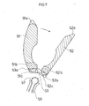
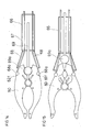
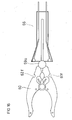
- FIGS. 8 to 13 show various views of a sixth embodiment of a disc prosthesis 60, while the FIGS. 14 to 23 represent how the disc prosthesis 60 can be inserted into the disc space.
- the disc prosthesis 60 has a first leg 61 and a second leg 62, wherein the first leg 61 has a first end 61a and a second end 61b, while the second leg 62 has a first end 62a and a second end 62b.
- the two legs 61, 62 each have a second recess 61d, 62d on the side face facing each other between the first end 61a, 62a and the second end 61b, 62b.
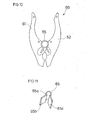
- the two legs 61, 62 are connected via a spring element 65 (see. Fig. 11 ), which, as described below, in the second recesses 61 d, 62 d of the legs 61, 62 engages.
- the spring element 65 has a substantially cylindrical portion 65a, which is slotted over the entire length, and on which, starting from the slot two anchoring wings 65b, 65c arranged are.
- the anchoring wings 65b, 65c are thus pivotable substantially about the longitudinal axis of the cylindrical portion 65a of the spring element 65.
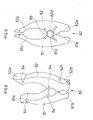
- an anchoring wing 65b, 65c engages in one of the second recess 61d, 62d of the legs 61, 62 (compare in particular Figures 9 and 10 ).
- FIG. 10 shows FIG. 10 the state of the spring element 65 without external force.
- the spring element 65 is thus relaxed when the two legs 61, 62 are spread apart from each other.
- FIG. 9 shows the spring element 65 in the loaded state.
- the two legs 61, 62 are transferred into a closed position, in which they extend in particular substantially parallel to each other.
- a first recess 61c, 62c is arranged on the mutually facing side surfaces of the legs 61, 62, through which in particular a bone screw connecting the two adjacent vertebral bodies is guided can.
- a plurality of X-ray contrast markers 64 are arranged, in particular in the region of the first ends 61a, 62a of the legs 61, 62 and in the region between the second recesses 61d, 62d and the first recesses 61c, 62c to track the insertion of the disc prosthesis 60 visually.
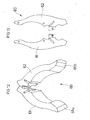
- FIGS. 14 to 16 show in detail the insertion instrument 66, which has a sleeve 67 in which axially displaceable two holding elements 68 and a Aufspreizelement 69 are arranged.
- the holding elements 68 have at their distal end gripping elements 68a, which in the present case are designed as balls or cylinders, which engage in substantially positive engagement in fourth recesses 61f, 62f arranged on the outer side surfaces of the legs 61, 62 facing away from the respective other leg 61, 62 ,
- the gripping elements 68a can thereby latch in the recesses 61f, 62f or be held in a clamping manner or only abut essentially in a form-fitting manner.
- the spreading element 69 has at its distal end an element 69a, which in the present case can also be designed as a spherical or cylindrical element 69a and engages in the third recess 61e, 62e of the intervertebral disc prosthesis 60.
- the spring element 65 widened against the spring force and the two legs 61, 62 transferred to a closed position.
- the gripping elements 68a of the holding elements 68 engage in the fourth recesses 61f, 62f of the legs 61, 62 in order to hold the intervertebral disc prosthesis 60.
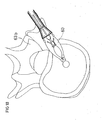
- the disc prosthesis 60 as in the Figures 17 and 18 shown in the intervertebral space between two adjacent vertebral bodies 63a, 63b are introduced.
- the expander 69 is axially retracted in the sleeve 67 of the Einsetzinstruments 66, so that by the force of the spring element 65
- FIG. 15 and FIG. 19 Legs 61, 62 are spread against each other (see FIG. 15 and FIG. 19 ).
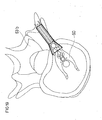
- the intervertebral disc prosthesis 60 can subsequently be moved to the desired position in the intervertebral space (cf. FIG. 19 ).
- the holding elements 68 can also be detached from the intervertebral disc prosthesis 60 by axially pulling out the holding elements 68 in the sleeve 67 of the insertion instrument 66 (see FIG Figures 16 and 20 ) and subsequently the insertion instrument 66 are completely removed from the surgical area (cf. FIG. 21 ).
- FIG. 21 FIG.
- FIG. 22 illustrates how a bone screw 63c, the intervertebral space and the intervertebral disc prosthesis 60 in particular in the region of the first recesses 61c, 62c of the legs 61, 62 transversely traversed, while in the FIGS. 17 to 21 the bone screw 63c is shown only in section.
- a side view of the installation situation of the intervertebral disc prosthesis 60 in the intervertebral space between the two adjacent vertebral bodies 63a, 63b shows FIG. 23 ,
- FIGS. 24 to 27 a seventh embodiment of a disc prosthesis 70 is shown, which has a first leg 71 having a first end 71a and a second end 71b and a second leg 72 having a first end 72a and a second end 72b.
- the two legs 71, 72 may be integrally connected or formed as a separate leg.
- a spring element 75 is arranged from a memory alloy between the two legs 71, 72.
- the memory alloy is in particular designed such that the shape is changed upon reaching the body temperature.
- FIG. 24 shows an intervertebral disc prosthesis 70 with the two legs 71, 72 in the closed position, in which the intervertebral disc prosthesis 70 in the intervertebral space can be introduced.
- FIG. 25 shows the expansion of the spring element 75 upon reaching the body temperature due to the memory effect, wherein the spring element 75 spreads such that the legs 71, 72 are pivoted against each other.
- the intervertebral disc 70 may then be moved to the desired position in the disc space with an insertion instrument 76, which is comparable to the insertion instrument 66 according to the sixth embodiment, to subsequently remove the insertion instrument 76, the intervertebral disc prosthesis 70 being displaced by the spring member 75 in FIG spread position remains.
- the spring element 75 according to the FIGS. 24 and 25 has two leaf spring leg-like elements.
- the spring element 75 may be formed as a split sleeve with two curved legs.
- the legs 11, 12, 21, 22, 31, 32, 41, 42, 51, 52, 61, 62, 71, 72 of the disc prostheses 10, 20, 30, 40, 50, 60, 70 can all be made of an elastic material be made.
- the legs 11, 12, 21, 22, 31, 32, 41, 42, 51, 52, 61, 62, 71, 72 are particularly preferably made of PEEK (polyether ether ketone).
Abstract
Description
Die Erfindung betrifft eine Bandscheibenprothese.The invention relates to a disc prosthesis.
Bekannt sind Bandscheibenprothesen zum Einsetzen in den Zwischenraum zwischen zwei benachbarten Wirbeln, welche eine defekte Bandscheibe ersetzen.Disc prostheses are known for insertion into the space between two adjacent vertebrae, which replace a defective disc.
Die Aufgabe der Erfindung besteht darin, eine Bandscheibenprothese bereitzustellen, welche flexibel einsetzbar ist.The object of the invention is to provide a disc prosthesis which can be used flexibly.
Die Aufgabe wird erfindungsgemäß gelöst durch eine Bandscheibenprothese zum Einsetzen zwischen zwei benachbarten Wirbelkörpern mit den Merkmalen des Patentanspruchs 1.The object is achieved by an intervertebral disc prosthesis for insertion between two adjacent vertebral bodies with the features of
Vorteilhafte Ausgestaltungen und Weiterbildungen der Erfindung sind in den abhängigen Ansprüchen angegeben.Advantageous embodiments and further developments of the invention are specified in the dependent claims.
Die erfindungsgemäße Bandscheibenprothese zum Einsetzen zwischen zwei benachbarten Wirbelkörpern zeichnet sich dadurch aus, dass die Bandscheibenprothese im Wesentlichen U-förmig ausgebildet ist mit ersten Schenkel und einem zweiten Schenkel, wobei die beiden Schenkel relativ zueinander verschwenkbar sind. Unter einen U-förmigen Form ist dabei insbesondere jede Geometrie zu verstehen, welche zwei Elemente mit einer Längserstreckung aufweist, die an einem Ende oder in der Nähe eines Endes entweder direkt oder mittels eines Verbindungselements miteinander verbunden sind und deren anderes Ende als freies Ende ausgebildet ist. Unter anderem wird unter einer U-förmigen Geometrie beispielsweise auch ein geschlitzter Ring oder eine C-förmige Geometrie verstanden. Insbesondere können die beiden Schenkel zusätzliche Geometrien, insbesondere in Form von Vorsprüngen oder Ausnehmungen, aufweisen, die insbesondere an die anatomischen Gegebenheiten angepasst sind.The intervertebral disc prosthesis according to the invention for insertion between two adjacent vertebral bodies is characterized in that the intervertebral disc prosthesis is substantially U-shaped with first leg and a second leg, wherein the two legs are pivotable relative to each other. In this case, a U-shaped form is to be understood in particular as meaning any geometry which has two elements with a longitudinal extension which are connected to one another at one end or near one end either directly or by means of a connecting element and whose other end is designed as a free end , Among other things, by a U-shaped geometry, for example, a slotted ring or a C-shaped geometry understood. In particular, the two legs can have additional geometries, in particular in FIG Shape of projections or recesses, which are particularly adapted to the anatomical conditions.
Die erfindungsgemäße Bandscheibenprothese weist den Vorteil auf, dass zum Einsetzen der Bandscheibenprothese die beiden Schenkel der U-förmigen Bandscheibenprothese möglichst eng aneinander liegen, sodass die Bandscheibenprothese durch einen kleinen Schnitt in der Haut eingeführt werden kann und anschließend im Zwischenwirbelraum die beiden Schenkel gegeneinander verschwenkt werden können, insbesondere in der Ebene der U-förmigen Bandscheibenprothese, welche insbesondere im implantierten Zustand quer zur Längsrichtung der Wirbelsäule verläuft, um durch das Aufschwenken die beiden benachbarten Wirbelkörper auf breiterer Fläche gegeneinander abzustützen. Insbesondere ermöglicht die U-förmige Ausgestaltung der Bandscheibenprothese das Einsetzen der Bandscheibenprothese, nachdem zwei benachbarte Wirbelkörper mittels einer Knochenschraube gegeneinander stabilisiert wurden, wobei die Knochenschraube den Zwischenwirbelraum quer durchsetzt. Die Bandscheibenprothese kann auch nach Einsetzen der Knochenschraube eingeführt werden derart, dass die beiden Schenkel der U-förmigen Bandscheibenprothese seitlich an der Knochenschraube vorbeigeführt werden und somit die beiden benachbarten Wirbel zuverlässig gegeneinander abstützt.The intervertebral disc prosthesis according to the invention has the advantage that for insertion of the intervertebral disc prosthesis the two legs of the U-shaped intervertebral disc prosthesis are as close as possible to each other, so that the intervertebral disc prosthesis can be inserted through a small incision in the skin and then in the intervertebral space, the two legs can be pivoted against each other , In particular in the plane of the U-shaped disc prosthesis, which extends transversely to the longitudinal direction of the spine, in particular in the implanted state, to support by pivoting the two adjacent vertebrae on a wider surface against each other. In particular, the U-shaped configuration of the intervertebral disc prosthesis allows insertion of the intervertebral disc prosthesis after two adjacent vertebral bodies have been stabilized against each other by means of a bone screw, wherein the bone screw traverses the intervertebral space transversely. The intervertebral disc prosthesis can also be inserted after insertion of the bone screw such that the two legs of the U-shaped intervertebral disc prosthesis are guided laterally past the bone screw and thus reliably supports the two adjacent vertebrae against one another.
Gemäß einer bevorzugten Ausführungsform der Erfindung ist die Bandscheibeprothese aus einem elastischen Material gefertigt, welches insbesondere ein Verschwenken der beiden Schenkel relativ zueinander ermöglicht.According to a preferred embodiment of the invention, the disc prosthesis is made of an elastic material, which in particular allows a pivoting of the two legs relative to each other.
Gemäß einer vorteilhaften Ausführungsform der Erfindung sind die beiden Schenkel jeweils über ein Scharnier schwenkbar angeordnet oder jeweils mittels eines Bolzens schwenkbar gelagert angeordnet, um ein definiertes, stufenloses Verschwenken der beiden Schenkel relativ zueinander zu ermöglichen.According to an advantageous embodiment of the invention, the two legs are each pivotally mounted via a hinge or pivotally mounted in each case by means of a bolt arranged to allow a defined, stepless pivoting of the two legs relative to each other.
Vorzugsweise weisen die beiden Schenkel einen Zahnradabschnitt auf, in welcher eine Aufspreizvorrichtung, insbesondere mittels eines Zahnradsabschnitts, zum Schwenken eingreifen kann. Auf diese Art und Weise wird ein definierter Aufspreizvorgang ermöglicht.Preferably, the two legs have a gear section, in which a spreading device, in particular by means of a gear section, can engage for pivoting. In this way, a defined Aufspreizvorgang is enabled.
Gemäß einer bevorzugten Ausführungsform der Erfindung sind die beiden Schenkel mittels eines Federelements, insbesondere eines Federelements aus einer Memorylegierung, verschwenkbar. Besonders bevorzugt ändert die Memorylegierung bei Erreichen der Körpertemperatur ihre Form, sodass beispielsweise die Bandscheibenprothese bei Raumtemperatur in den Zwischenwirbelraum gesetzt werden kann, wobei das Federelement derart angeordnet ist, dass die beiden Schenkel nahezu oder direkt aneinander liegen, und nach Einsetzen der Bandscheibenprothese, sobald die Bandscheibenprothese und das Federelement die Körpertemperatur erreicht haben, die beiden Schenkel mittels des Federelements gegeneinander verschwenkt werden, sobald die Memoreglegierung ihre Form ändert.According to a preferred embodiment of the invention, the two legs are pivotable by means of a spring element, in particular a spring element made of a memory alloy. When the body temperature is reached, the memory alloy particularly preferably changes its shape so that, for example, the intervertebral disc prosthesis can be placed in the intervertebral space at room temperature, wherein the spring element is arranged such that the two limbs almost or directly abut each other, and once the intervertebral disc prosthesis has been inserted Intervertebral disc prosthesis and the spring element have reached the body temperature, the two legs are pivoted against each other by means of the spring element, as soon as the Memoreglegierung changes shape.
Vorteilhafterweise ist an einem der beiden Schenkel ein Hebelelement schwenkbar gelagert angeordnet, welches bei Drehung um eine Drehachse an einer an dem anderen der beiden Schenkel angeordneten Zwangskurve angreift, um die beiden Schenkel relativ zueinander verschwenken. Auf diese Art und Weise wird ein stufenloses Verschwenken der beiden Schenkel relativ zueinander auf einfache Art und Weise realisiert.Advantageously, a lever element is pivotably mounted on one of the two legs, which engages on rotation about an axis of rotation on a force curve arranged on the other of the two legs to pivot the two legs relative to each other. In this way, a stepless pivoting of the two legs relative to each other is realized in a simple manner.
Gemäß einer bevorzugten Ausführungsform der Erfindung sind die freien Enden der Schenkel aufeinander zugebogen, sodass auch bei aufgespreizter Bandscheibenprothese eine zuverlässige Abstützung der beiden benachbarten Wirbelkörper sowohl in sagittaler Richtung als auch in seitlicher Richtung gewährleistet ist.According to a preferred embodiment of the invention, the free ends of the legs are bent towards each other, so also with spread disc prosthesis reliable support of the two adjacent vertebral bodies is ensured both in the sagittal direction and in the lateral direction.
Vorzugsweise sind an der Bandscheibenprothese wenigstens zwei vorzugsweise drei, Röntgenkontrastmarker angeordnet, um das Einsetzen der Bandscheibenprothese visuell verfolgen zu können.Preferably, at least two, preferably three, X-ray contrast markers are arranged on the intervertebral disc prosthesis in order to be able to visually follow the insertion of the intervertebral disc prosthesis.
Vorzugsweise weisen die beiden Schenkel jeweils ein freies Ende auf, welches mit einem Röntgenkontrastmittel, beispielsweise mit Tantal beschichtet ist, um das Einsetzen der Bandscheibenprothese, welches mit den freien Enden der Schenkel voran erfolgt, zuverlässig visuell verfolgen zu können.Preferably, the two legs each have a free end, which is coated with an X-ray contrast agent, for example with tantalum, in order to reliably track the onset of the disc prosthesis, which takes place with the free ends of the legs ahead.
Gemäß einer bevorzugten Ausführungsform der Erfindung weist einer der beiden Schenkel in der Ebene der U-förmigen Bandscheibenprothese eine größere Breite auf als der andere der beiden Schenkel, um insbesondere auch bei einer asymmetrisch durch den Zwischenraum zwischen den beiden benachbarten Wirbel verlaufenden Knochenschraube eine zuverlässige Abstützung der beiden benachbarten Wirbel gegeneinander gewährleisten zu können.According to a preferred embodiment of the invention, one of the two legs in the plane of the U-shaped intervertebral disc prosthesis has a greater width than the other of the two legs to a reliable support especially in an asymmetrically extending through the space between the two adjacent vertebra bone screw to ensure two adjacent vertebrae against each other.
Vorzugsweise weist die Bandscheibenprothese wenigstens eine Ausnehmung auf, in welcher ein Einsetzinstrument eingreifen kann, um die Bandscheibenprothese während des Einsetzvorgangs definiert halten zu können.Preferably, the intervertebral disc prosthesis has at least one recess in which an insertion instrument can engage in order to be able to hold the intervertebral disc prosthesis defined during the insertion process.
Gemäß einer besonders bevorzugten Ausführungsform der Erfindung ist das Einsetzinstrument gleichzeitig geeignet, nach Einsetzen der Bandscheibenprothese die beiden Schenkel der Bandscheibenprothese aufzuspreizen.According to a particularly preferred embodiment of the invention, the insertion instrument is simultaneously suitable, according to Insertion of the intervertebral disc prosthesis spread the two legs of the intervertebral disc prosthesis.
Die Erfindung wird anhand der nachfolgenden Figuren ausführlich erläutert.The invention will be explained in detail with reference to the following figures.
Es zeigt:
- Fig. 1
- eine schematische Darstellung eines ersten Ausführungsbeispiels einer erfindungsgemäßen Bandscheibenprothese,
- Fig. 2
- eine schematische Ansicht eines zweiten Ausführungsbeispiels einer erfindungsgemäßen Bandscheibenprothese,
- Fig. 3
- eine schematische Ansicht eines dritten Ausführungsbeispiels einer erfindungsgemäßen Bandscheibenprothese,
- Fig. 4
- eine schematische Ansicht eines vierten Ausführungsbeispiels einer erfindungsgemäßen Bandscheibenprothese,
- Fig. 5
- eine schematische Ansicht eines fünften Ausführungsbeispiels einer erfindungsgemäßen Bandscheibenprothese,
- Fig. 6
- eine Seitenansicht der Bandscheibenprothese gemäß
Figur 5 , - Fig. 7
- die Bandscheibenprothese gemäß
Figur 5 in aufgeschwenktem Zustand, - Fig. 8
- eine schematische perspektivische Darstellung eines sechsten Ausführungsbeispiels einer erfindungsgemäßen Bandscheibenprothese,
- Fig. 9
- eine Draufsicht auf die Bandscheibenprothese gemäß
Figur 8 in zusammengeklapptem Zustand, - Fig. 10
- die Bandscheibenprothese gemäß
Figur 8 in aufgeschwenktem Zustand, - Fig. 11
- eine perspektivische Darstellung des Federelements der Bandscheibenprothese gemäß
Figur 9 , - Fig. 12
- eine perspektivische Darstellung der Bandscheibenprothese gemäß
Figur 8 in aufgespreiztem Zustand, - Fig. 13
- eine Draufsicht auf die zerlegte Bandscheibenprothese gemäß
Figur 8 , - Fig. 14
- die Bandscheibenprothese gemäß
Figur 8 in zusammengeklapptem Zustand, welche in einen Halter eingesetzt ist, - Fig. 15
- die Bandscheibenprothese gemäß
Figur 8 in aufgespreiztem Zustand, welche in einen Halter eingesetzt ist, - Fig. 16
- die Bandscheibenprothese gemäß
Figur 8 mit davon gelöstem Halter, - Fig. 17
- eine Darstellung des Einführens der Bandscheibenprothese gemäß
Figur 8 in einen Zwischenwirbelraum, - Fig. 18
- eine weitere Darstellung des Einsetzens der Bandscheibenprothese gemäß
Figur 8 in einen Zwischenwirbelraum, - Fig. 19
- eine weitere Darstellung des Einsetzens der Bandscheibenprothese gemäß
Figur 8 in einen Zwischenwirbelraum, - Fig. 20
- eine weitere Darstellung des Einsetzens der Bandscheibenprothese gemäß
Figur 8 in einen Zwischenwirbelraum, - Fig. 21
- eine weitere Darstellung des Einsetzens der Bandscheibenprothese gemäß
Figur 8 in einen Zwischenwirbelraum, - Fig. 22
- die Bandscheibenprothese gemäß
Figur 8 im in den Zwischenraum eingesetzten Zustand mit schematischer perspektivischer Darstellung einer Knochenschraube, - Fig. 23
- eine Seitenansicht der Bandscheibenprothese 8 im in den Zwischenraum zwischen zwei benachbarten Wirbeln eingesetzten Zustand mit schematischer Darstellung der Knochenschraube,
- Fig. 24
- ein siebtes Ausführungsbeispiel einer erfindungsgemäßen Bandscheibenprothese mit Halter,
- Fig. 25
- die Bandscheibenprothese gemäß
Figur 24 mit Halter, - Fig. 26
- die Bandscheibenprothese gemäß
Figur 24 mit einem alternativen Federelement und - Fig. 27
- die
Bandscheibenprothese gemäß Figur 26 in einer weiteren Position.
- Fig. 1
- a schematic representation of a first embodiment of a disc prosthesis according to the invention,
- Fig. 2
- a schematic view of a second embodiment of a disc prosthesis according to the invention,
- Fig. 3
- a schematic view of a third embodiment of a disc prosthesis according to the invention,
- Fig. 4
- a schematic view of a fourth embodiment of a disc prosthesis according to the invention,
- Fig. 5
- a schematic view of a fifth embodiment of a disc prosthesis according to the invention,
- Fig. 6
- a side view of the disc prosthesis according to
FIG. 5 . - Fig. 7
- the intervertebral disc prosthesis according to
FIG. 5 in swung-open condition, - Fig. 8
- a schematic perspective view of a sixth embodiment of a disc prosthesis according to the invention,
- Fig. 9
- a plan view of the disc prosthesis according to
FIG. 8 in folded state, - Fig. 10
- the intervertebral disc prosthesis according to
FIG. 8 in swung-open condition, - Fig. 11
- a perspective view of the spring element of the disc prosthesis according to
FIG. 9 . - Fig. 12
- a perspective view of the disc prosthesis according to
FIG. 8 in a spread state, - Fig. 13
- a plan view of the dissected disc prosthesis according to
FIG. 8 . - Fig. 14
- the intervertebral disc prosthesis according to
FIG. 8 in the folded state, which is inserted in a holder, - Fig. 15
- the intervertebral disc prosthesis according to
FIG. 8 in a spread state, which is inserted in a holder, - Fig. 16
- the intervertebral disc prosthesis according to
FIG. 8 with a holder detached therefrom, - Fig. 17
- a representation of the insertion of the intervertebral disc prosthesis according to
FIG. 8 in an intervertebral space, - Fig. 18
- a further illustration of the insertion of the disc prosthesis according to
FIG. 8 in an intervertebral space, - Fig. 19
- a further illustration of the insertion of the disc prosthesis according to
FIG. 8 in an intervertebral space, - Fig. 20
- a further illustration of the insertion of the disc prosthesis according to
FIG. 8 in an intervertebral space, - Fig. 21
- a further illustration of the insertion of the disc prosthesis according to
FIG. 8 in an intervertebral space, - Fig. 22
- the intervertebral disc prosthesis according to
FIG. 8 in the inserted state in the intermediate space with a schematic perspective view of a bone screw, - Fig. 23
- a side view of the intervertebral disc prosthesis 8 in the inserted into the space between two adjacent vertebrae state with a schematic representation of the bone screw,
- Fig. 24
- A seventh embodiment of a disc prosthesis according to the invention with holder,
- Fig. 25
- the intervertebral disc prosthesis according to
FIG. 24 with Holder, - Fig. 26
- the intervertebral disc prosthesis according to
FIG. 24 with an alternative spring element and - Fig. 27
- the intervertebral disc prosthesis according to
FIG. 26 in another position.
In allen Figuren bezeichnen gleiche Bezugsziffern stets gleiche Teile, wobei zur besseren Übersicht oft nicht sämtliche Bezugsziffern in jeder Figur angegeben sind.In all figures, like reference numerals always refer to the same parts, for better clarity often not all reference numerals are given in each figure.
Die
Um das Einführen und Positionieren der Bandscheibenprothese 50 in dem Zwischenwirbelraum visuell nachfolgen zu können, sind insbesondere die ersten Enden 51a, 52a mit einem Röntgenkontrastmaterial, beispielsweise mit Tantal beschichtet. Vorzugsweise ist an dritter Stelle ein weiterer Röntgenkontrastmarker angeordnet. Bevorzugt sind wenigstens drei Röntgenkontrastmarker an der Bandscheibenprothese 50 angeordnet, die auch nicht notwendigerweise an den freien Enden 51a, 52a der Schenkel 51, 52 angeordnet sein müssen. Selbstverständlich können die Röntgenkontrastmarker auch bei sämtlichen anderen in der vorliegenden Anmeldung beschriebenen Bandscheibenprothesen verwendet werden.In order to be able to visually follow the introduction and positioning of the
Die Schenkel 51, 52 weisen an den einander zugewandten Seitenflächen jeweils eine Aussparung 51d, 52d auf. Durch diesen Bereich kann insbesondere eine Knochenschraube, die zwei benachbarte Wirbelkörper gegeneinander stabilisiert, geführt werden.The
Wie in der Seitenansicht gemäß
Insbesondere weisen die Ober- und/oder Unterseite der Bandscheibenprothese 50 Zähne 55 auf, um ein Verankern der Bandscheibenprothese 50 in dem benachbarten Wirbelkörpern zu verbessern.In particular, the top and / or bottom of the
Der erste Schenkel 51 weist vorliegend eine größere Seite auf als der Schenkel 52 (vergleiche
Die
Die Bandscheibenprothese 60 weist einen ersten Schenkel 61 und einen zweiten Schenkel 62 auf, wobei der erste Schenkel 61 ein erstes Ende 61a und ein zweites Ende 61b aufweist, während der zweite Schenkel 62 ein erstes Ende 62a und ein zweites Ende 62b aufweist. Die beiden Schenkel 61, 62 weisen jeweils an der einander zugewandten Seitenfläche jeweils zwischen dem ersten Ende 61a, 62a und dem zweiten Ende 61b, 62b eine zweite Ausnehmung 61d, 62d auf. Die beiden Schenkel 61, 62 sind über ein Federelement 65 (vgl.
Zwischen den zweiten Ausnehmungen 61d, 62d und den ersten Enden 61a, 62a der Schenkel 61, 62 ist auf den einander zugewandten Seitenflächen der Schenkel 61, 62 eine erste Ausnehmung 61c, 62c angeordnet, durch welche insbesondere eine die beiden benachbarten Wirbelkörper verbindende Knochenschraube geführt werden kann.Between the
Zwischen den zweiten Ausnehmungen 61d, 62d und den zweiten Enden 61b, 62b der Schenkel 61, 62 ist auf den einander zugewandten Seitenflächen der Schenkel 61, 62 eine dritte Ausnehmung 61e, 62e angeordnet, in welche wie nachfolgend anhand der
An den Schenkeln 61, 62 sind mehrere Röntgenkontrastmarker 64 angeordnet, insbesondere im Bereich der ersten Enden 61a, 62a der Schenkel 61, 62 und im Bereich zwischen den zweiten Ausnehmungen 61d, 62d und den ersten Ausnehmungen 61c, 62c, um das Einsetzen der Bandscheibenprothese 60 visuell nachverfolgen zu können.On the
Die
Wie in
Schenkel 61, 62 gegeneinander aufgespreizt werden (vergleiche
In den
Die Bandscheibe 70 kann anschließend mit einem Einsetzinstrument 76, welches vergleichbar zu dem Einsetzinstrument 66 gemäß dem sechsten Ausführungsbeispiel ist, in die gewünschte Position in dem Zwischenwirbelraum bewegt werden, um das Einsetzinstrument 76 anschließend zu entfernen, wobei die Bandscheibenprothese 70 durch das Federelement 75 in der aufgespreizten Position verbleibt. Das Federelement 75 gemäß der
Die Merkmale aus den unterschiedlichen Ausführungsbeispielen können auch beliebig kombiniert werden.The features of the different embodiments can also be combined arbitrarily.
Die Schenkel 11, 12, 21, 22, 31, 32, 41, 42, 51, 52, 61, 62, 71, 72 der Bandscheibenprothesen 10, 20, 30, 40, 50, 60, 70 können sämtlich aus einem elastischen Material gefertigt sein. Besonders bevorzugt sind die Schenkel 11, 12, 21, 22, 31, 32, 41, 42, 51, 52, 61, 62, 71, 72 jedoch aus PEEK (Polyetheretherketon) gefertigt.The
- 1010
- BandscheibenprotheseDisc prosthesis
- 1111
- erster Schenkelfirst leg
- 11a11a
- erstes Endefirst end
- 11b11b
- zweites Endesecond end
- 1212
- zweiter Schenkelsecond leg
- 12a12a
- erstes Endefirst end
- 12b12b
- erstes Endefirst end
- 2020
- BandscheibenprotheseDisc prosthesis
- 2121
- erster Schenkelfirst leg
- 21a21a
- erstes Endefirst end
- 21b21b
- zweites Endesecond end
- 2222
- zweiter Schenkelsecond leg
- 22a22a
- erstes Endefirst end
- 22b22b
- zweites Endesecond end
- 2525
- Bolzenbolt
- 2626
- Aufspreizelementspreading element
- 2727
- Halterholder
- 3030
- BandscheibenprotheseDisc prosthesis
- 3131
- erster Schenkelfirst leg
- 31a31a
- erstes Endefirst end
- 31b31b
- zweites Endesecond end
- 3232
- zweiter Schenkelsecond leg
- 32a32a
- erstes Endefirst end
- 32b32b
- zweites Endesecond end
- 3535
- Bolzenbolt
- 3636
- Hebelelementlever member
- 3737
- Zwangskurveforced curve
- xx
- Schwenkrichtungpan direction
- yy
- Schwenkrichtungpan direction
- 4040
- BandscheibenprotheseDisc prosthesis
- 4141
- erster Schenkelfirst leg
- 41a41a
- erstes Endefirst end
- 41b41b
- zweites Endesecond end
- 4242
- zweiter Schenkelsecond leg
- 42a42a
- erstes Endefirst end
- 42b42b
- zweites Endesecond end
- 4545
- Zylindergelenkcylindrical joint
- 4646
- Betätigungselementactuator
- 5050
- BandscheibenprotheseDisc prosthesis
- 5151
- erster Schenkelfirst leg
- 51a51a
- erstes Endefirst end
- 51b51b
- zweites Endesecond end
- 51c51c
- Zahnradabschnittgear portion
- 51d51d
- Ausnehmungrecess
- 5252
- zweiter Schenkelsecond leg
- 52a52a
- erstes Endefirst end
- 52b52b
- zweites Endesecond end
- 52c52c
- Zahnradabschnittgear portion
- 52d52d
- Ausnehmungrecess
- 5353
- Verbindungselementconnecting element
- 53a53a
- Bolzenbolt
- 53b53b
- Bolzenbolt
- 5555
- Zahntooth
- 5656
- Aufspreizelementspreading element
- 5757
- Zahnradabschnittgear portion
- 6060
- BandscheibenprotheseDisc prosthesis
- 6161
- Schenkelleg
- 61a61a
- erstes Endefirst end
- 61b61b
- zweites Endesecond end
- 61c61c
- erste Ausnehmungfirst recess
- 61d61d
- zweite Ausnehmungsecond recess
- 61e61e
- dritte Ausnehmungthird recess
- 61f61f
- vierte Ausnehmungfourth recess
- 6262
- zweiter Schenkelsecond leg
- 62a62a
- erstes Endefirst end
- 62b62b
- zweites Endesecond end
- 62c62c
- erste Ausnehmungfirst recess
- 62d62d
- zweite Ausnehmungsecond recess
- 62e62e
- dritte Ausnehmungthird recess
- 62f62f
- vierte Ausnehmungfourth recess
- 63a63a
- Wirbelkörpervertebra
- 63b63b
- Wirbelkörpervertebra
- 63c63c
- Knochenschraubebone screw
- 6464
- RöntgenkontrastmarkerRadiopaque markers
- 6565
- Federelementspring element
- 65a65a
- zylindrischer Abschnittcylindrical section
- 65b65b
- Verankerungsflügelanchoring wing
- 65c65c
- Verankerungsflügelanchoring wing
- 6666
- Einsetzinstrumentinsertion
- 6767
- Hülseshell
- 6868
- Halteelementretaining element
- 68a68a
- Greifelementgripping element
- 6969
- Aufspreizelementspreading element
- 69a69a
- Elementelement
- 7070
- BandscheibenprotheseDisc prosthesis
- 7171
- Schenkelleg
- 71a71a
- erstes Endefirst end
- 71b71b
- zweites Endesecond end
- 7272
- zweiter Schenkelsecond leg
- 72a72a
- erstes Endefirst end
- 72b72b
- zweites Endesecond end
- 7575
- Federelementspring element
- 7676
- Einsetzinstrumentinsertion
Claims (12)
dadurch gekennzeichnet, dass die Bandscheibenprothese (10, 20, 30, 40, 50, 60, 70) im wesentlichen U-förmig ausgebildet ist mit einem ersten Schenkel (11, 21, 31, 41, 51, 61, 71) und einem zweiten Schenkel (12, 22, 32, 42, 52, 62, 72), wobei die beiden Schenkel (11, 12, 21, 22, 31, 32, 41, 52, 51, 52, 61, 62, 71, 72) relativ zueinander verschwenkbar sind.Intervertebral disc prosthesis (10, 20, 30, 40, 50, 60, 70) for insertion between two adjacent vertebral bodies (63a, 63b),
characterized in that the disc prosthesis (10, 20, 30, 40, 50, 60, 70) is substantially U-shaped with a first leg (11, 21, 31, 41, 51, 61, 71) and a second Leg (12, 22, 32, 42, 52, 62, 72), wherein the two legs (11, 12, 21, 22, 31, 32, 41, 52, 51, 52, 61, 62, 71, 72) are pivotable relative to each other.
dadurch gekennzeichnet, dass die Bandscheibenprothese (10, 20, 30, 40, 50, 60, 70) aus einem elastischen Material gefertigt ist.Intervertebral disc prosthesis according to claim 1,
characterized in that the disc prosthesis (10, 20, 30, 40, 50, 60, 70) is made of an elastic material.
dadurch gekennzeichnet, dass die beiden Schenkel (11, 12, 21, 22, 31, 32, 41, 52, 51, 52, 61, 62, 71, 72) jeweils über ein Scharnier schwenkbar angeordnet sind.Intervertebral disc prosthesis according to one of the preceding claims,
characterized in that the two legs (11, 12, 21, 22, 31, 32, 41, 52, 51, 52, 61, 62, 71, 72) are each pivotally mounted via a hinge.
dadurch gekennzeichnet, dass die beiden Schenkel (21, 22, 31, 32, 41, 42) jeweils mittels eines Bolzens (25, 35, 53a, 53b) schwenkbar gelagert angeordnet sind.Intervertebral disc prosthesis according to one of the preceding claims,
characterized in that the two legs (21, 22, 31, 32, 41, 42) in each case by means of a bolt (25, 35, 53 a, 53 b) are arranged pivotably mounted.
dadurch gekennzeichnet, dass die beiden Schenkel (51, 52) einen Zahnradabschnitt (51c, 52c) aufweisen, in welche ein Aufspreizelement (56), insbesondere mittels eines Zahnradabschnitts (57), zum Schwenken eingreifen kann.Intervertebral disc prosthesis according to one of the preceding claims,
characterized in that the two legs (51, 52) have a gear portion (51c, 52c), in which a Aufspreizelement (56), in particular by means of a gear portion (57), can engage for pivoting.
dadurch gekennzeichnet, dass die beiden Schenkel (61, 62, 71, 72) mittels eines Federelements (65, 75), insbesondere eines Federelements (75) aus einer Memorylegierung, verschwenkbar sind.Intervertebral disc prosthesis according to one of the preceding claims,
characterized in that the two legs (61, 62, 71, 72) by means of a spring element (65, 75), in particular a spring element (75) made of a memory alloy, are pivotable.
dadurch gekennzeichnet, dass an dem einen der beiden Schenkel (31, 32) ein Hebelelement (36) schwenkbar gelagert angeordnet ist, welches bei Drehung um eine Drehachse an einer an dem anderen der beiden Schenkel (31, 32)angeordneten Zwangskurve (37) angreift, um die beiden Schenkel (31, 32) relativ zueinander zu verschwenken.Intervertebral disc prosthesis according to one of the preceding claims,
characterized in that on one of the two legs (31, 32) a lever element (36) is pivotally mounted, which engages on rotation about an axis of rotation on one of the other of the two legs (31, 32) arranged compulsory curve (37) to pivot the two legs (31, 32) relative to each other.
dadurch gekennzeichnet, dass die freien Enden (11a, 12a, 21a, 22a, 31a, 32a, 41a, 42a, 51a, 52a, 61a, 62a, 71a, 72a) der Schenkel (11, 12, 21, 22, 31, 32, 41, 42, 51, 52, 61, 62, 71, 72) aufeinander zu gebogen sind.Intervertebral disc prosthesis according to one of the preceding claims,
characterized in that the free ends (11a, 12a, 21a, 22a, 31a, 32a, 41a, 42a, 51a, 52a, 61a, 62a, 71a, 72a) of the legs (11, 12, 21, 22, 31, 32 , 41, 42, 51, 52, 61, 62, 71, 72) are bent towards each other.
dadurch gekennzeichnet, dass wenigstens zwei, vorzugsweise drei, Röntgenkontrastmarker (64) an der Bandscheibenprothese (10, 20, 30, 40, 50, 60, 70) angeordnet sind.Intervertebral disc prosthesis according to one of the preceding claims,
characterized in that at least two, preferably three, X-ray contrast markers (64) on the disc prosthesis (10, 20, 30, 40, 50, 60, 70) are arranged.
dadurch gekennzeichnet, dass die beiden Schenkel (11, 12, 21, 22, 31, 32, 41, 42, 51, 52, 61, 62, 71, 72) jeweils ein freies Ende (11a, 12a, 21a, 22a, 31a, 32a, 41a, 42a, 51a, 52a, 61a, 62a, 71a, 72a) aufweisen, welches mit einem Röntgenkontrastmaterial, beispielsweise mit Tantal, beschichtet ist.Intervertebral disc prosthesis according to one of the preceding claims,
characterized in that the two legs (11, 12, 21, 22, 31, 32, 41, 42, 51, 52, 61, 62, 71, 72) each have a free end (11a, 12a, 21a, 22a, 31a , 32a, 41a, 42a, 51a, 52a, 61a, 62a, 71a, 72a) which is coated with an X-ray contrast material, for example with tantalum.
dadurch gekennzeichnet, dass einer der beiden Schenkel (51) in der Ebene der U-förmigen Bandscheibenprothese (50) eine größere Breite aufweist als der andere der beiden Schenkel (52).Intervertebral disc prosthesis according to one of the preceding claims,
characterized in that one of the two legs (51) in the plane of the U-shaped disc prosthesis (50) has a greater width than the other of the two legs (52).
dadurch gekennzeichnet, dass die Bandscheibenprothese (60, 70) wenigstens eine Ausnehmung (61f, 62f) aufweist, in welche ein Einsetzinstrument (66, 76) eingreifen kann.Intervertebral disc prosthesis according to one of the preceding claims,
characterized in that the disc prosthesis (60, 70) has at least one recess (61f, 62f) into which an insertion instrument (66, 76) can engage.
Priority Applications (2)
| Application Number | Priority Date | Filing Date | Title |
|---|---|---|---|
| EP10013959.1A EP2446860B1 (en) | 2010-10-26 | 2010-10-26 | Spinal disc prosthesis |
| ES10013959.1T ES2564289T3 (en) | 2010-10-26 | 2010-10-26 | Intervertebral disc prosthesis |
Applications Claiming Priority (1)
| Application Number | Priority Date | Filing Date | Title |
|---|---|---|---|
| EP10013959.1A EP2446860B1 (en) | 2010-10-26 | 2010-10-26 | Spinal disc prosthesis |
Publications (2)
| Publication Number | Publication Date |
|---|---|
| EP2446860A1 true EP2446860A1 (en) | 2012-05-02 |
| EP2446860B1 EP2446860B1 (en) | 2015-12-02 |
Family
ID=43743488
Family Applications (1)
| Application Number | Title | Priority Date | Filing Date |
|---|---|---|---|
| EP10013959.1A Not-in-force EP2446860B1 (en) | 2010-10-26 | 2010-10-26 | Spinal disc prosthesis |
Country Status (2)
| Country | Link |
|---|---|
| EP (1) | EP2446860B1 (en) |
| ES (1) | ES2564289T3 (en) |
Cited By (4)
| Publication number | Priority date | Publication date | Assignee | Title |
|---|---|---|---|---|
| US9198765B1 (en) | 2011-10-31 | 2015-12-01 | Nuvasive, Inc. | Expandable spinal fusion implants and related methods |
| US9445918B1 (en) | 2012-10-22 | 2016-09-20 | Nuvasive, Inc. | Expandable spinal fusion implants and related instruments and methods |
| WO2016145542A1 (en) * | 2015-03-18 | 2016-09-22 | Startech Engineering Ag | Expandable spinal implant |
| CN109152645A (en) * | 2016-03-30 | 2019-01-04 | 阿比菲克斯有限公司 | Adjustable backbone cage |
Citations (14)
| Publication number | Priority date | Publication date | Assignee | Title |
|---|---|---|---|---|
| FR2771282A1 (en) * | 1997-11-25 | 1999-05-28 | Jean Taylor | Surgical support implant for spine |
| EP0965313A1 (en) * | 1998-06-17 | 1999-12-22 | Ulrich GmbH & Co. KG | Implant for fusion of two vertebraes |
| WO2000025706A1 (en) * | 1998-10-29 | 2000-05-11 | Sdgi Holdings, Inc. | Expandable intervertebral spacers |
| WO2000040179A1 (en) * | 1999-01-08 | 2000-07-13 | Sdgi Holdings, Inc. | Flexible implant using partially demineralized bone |
| US6368351B1 (en) * | 2001-03-27 | 2002-04-09 | Bradley J. Glenn | Intervertebral space implant for use in spinal fusion procedures |
| US6454807B1 (en) * | 2000-11-30 | 2002-09-24 | Roger P. Jackson | Articulated expandable spinal fusion cage system |
| WO2004037067A2 (en) * | 2002-10-21 | 2004-05-06 | 3Hbfm, Llc | Intervertebral disk prosthesis |
| US20040249461A1 (en) * | 1999-08-13 | 2004-12-09 | Ferree Bret A. | Coupled artificial disc replacements methods and apparatus |
| US20050021144A1 (en) * | 2003-07-23 | 2005-01-27 | Malberg Marc I. | Expandable spinal implant |
| US20060004448A1 (en) * | 2004-06-30 | 2006-01-05 | Depuy Spine, Inc. | Multi-joint implant |
| US20080154377A1 (en) * | 2006-12-22 | 2008-06-26 | Voellmicke John C | Composite vertebral spacers and instrument |
| US20090048676A1 (en) * | 2005-09-27 | 2009-02-19 | Fabian Jr Henry F | Spine surgery method and motion preserving implant |
| US20100016973A1 (en) * | 2008-07-18 | 2010-01-21 | Spinalmotion, Inc. | Posterior Prosthetic Intervertebral Disc |
| WO2010092613A1 (en) * | 2009-02-13 | 2010-08-19 | 2B1 S.R.L. | Intervertebral disc prosthesis for stabilizing the lumbar spine and relevant kit |
-
2010
- 2010-10-26 ES ES10013959.1T patent/ES2564289T3/en active Active
- 2010-10-26 EP EP10013959.1A patent/EP2446860B1/en not_active Not-in-force
Patent Citations (14)
| Publication number | Priority date | Publication date | Assignee | Title |
|---|---|---|---|---|
| FR2771282A1 (en) * | 1997-11-25 | 1999-05-28 | Jean Taylor | Surgical support implant for spine |
| EP0965313A1 (en) * | 1998-06-17 | 1999-12-22 | Ulrich GmbH & Co. KG | Implant for fusion of two vertebraes |
| WO2000025706A1 (en) * | 1998-10-29 | 2000-05-11 | Sdgi Holdings, Inc. | Expandable intervertebral spacers |
| WO2000040179A1 (en) * | 1999-01-08 | 2000-07-13 | Sdgi Holdings, Inc. | Flexible implant using partially demineralized bone |
| US20040249461A1 (en) * | 1999-08-13 | 2004-12-09 | Ferree Bret A. | Coupled artificial disc replacements methods and apparatus |
| US6454807B1 (en) * | 2000-11-30 | 2002-09-24 | Roger P. Jackson | Articulated expandable spinal fusion cage system |
| US6368351B1 (en) * | 2001-03-27 | 2002-04-09 | Bradley J. Glenn | Intervertebral space implant for use in spinal fusion procedures |
| WO2004037067A2 (en) * | 2002-10-21 | 2004-05-06 | 3Hbfm, Llc | Intervertebral disk prosthesis |
| US20050021144A1 (en) * | 2003-07-23 | 2005-01-27 | Malberg Marc I. | Expandable spinal implant |
| US20060004448A1 (en) * | 2004-06-30 | 2006-01-05 | Depuy Spine, Inc. | Multi-joint implant |
| US20090048676A1 (en) * | 2005-09-27 | 2009-02-19 | Fabian Jr Henry F | Spine surgery method and motion preserving implant |
| US20080154377A1 (en) * | 2006-12-22 | 2008-06-26 | Voellmicke John C | Composite vertebral spacers and instrument |
| US20100016973A1 (en) * | 2008-07-18 | 2010-01-21 | Spinalmotion, Inc. | Posterior Prosthetic Intervertebral Disc |
| WO2010092613A1 (en) * | 2009-02-13 | 2010-08-19 | 2B1 S.R.L. | Intervertebral disc prosthesis for stabilizing the lumbar spine and relevant kit |
Cited By (10)
| Publication number | Priority date | Publication date | Assignee | Title |
|---|---|---|---|---|
| US9198765B1 (en) | 2011-10-31 | 2015-12-01 | Nuvasive, Inc. | Expandable spinal fusion implants and related methods |
| US9655744B1 (en) | 2011-10-31 | 2017-05-23 | Nuvasive, Inc. | Expandable spinal fusion implants and related methods |
| US9445918B1 (en) | 2012-10-22 | 2016-09-20 | Nuvasive, Inc. | Expandable spinal fusion implants and related instruments and methods |
| US10350084B1 (en) | 2012-10-22 | 2019-07-16 | Nuvasive, Inc. | Expandable spinal fusion implant, related instruments and methods |
| US11399954B2 (en) | 2012-10-22 | 2022-08-02 | Nuvasive, Inc. | Expandable spinal fusion implant, related instruments and methods |
| WO2016145542A1 (en) * | 2015-03-18 | 2016-09-22 | Startech Engineering Ag | Expandable spinal implant |
| US10398564B2 (en) | 2015-03-18 | 2019-09-03 | 41Medical Ag | Expandable spinal implant |
| AU2015387084B2 (en) * | 2015-03-18 | 2020-02-13 | 41Medical Ag | Expandable spinal implant |
| CN109152645A (en) * | 2016-03-30 | 2019-01-04 | 阿比菲克斯有限公司 | Adjustable backbone cage |
| CN109152645B (en) * | 2016-03-30 | 2021-05-07 | 爱復股份有限公司 | Adjustable spinal cage |
Also Published As
| Publication number | Publication date |
|---|---|
| EP2446860B1 (en) | 2015-12-02 |
| ES2564289T3 (en) | 2016-03-21 |
Similar Documents
| Publication | Publication Date | Title |
|---|---|---|
| EP1574173B1 (en) | Elastic rod-shaped element for use in spinal or accident surgery and stabilising device comprising such an element | |
| EP3117787B1 (en) | Pedicle screw with tulip | |
| EP2114274B1 (en) | Plate-implant, in particular for use on a spinal column | |
| EP2480149B1 (en) | Rod connector for cross-connecting of two spinal rods | |
| DE10157814B4 (en) | Closure device for securing a rod-shaped element in a holding element connected to a shaft | |
| EP2621383B1 (en) | Bilateral lamina implant | |
| EP1684652A1 (en) | Bone fixing element and stabilising device comprising one such bone fixing element | |
| WO2005044123A1 (en) | Bone fixing element and stabilising device comprising one such bone fixing element | |
| EP1523949A1 (en) | Surgical rod element, stabilisation device, and method of manufacturing the element | |
| WO2014146797A1 (en) | Instrument set and method for introducing a cage into the intervertebral disc space | |
| EP2226039B1 (en) | Implant for the thoracic and lumbar spine | |
| EP1481654A1 (en) | Intervertebral fusion implant and instrument for placement and distraction of said implant | |
| EP1774927B1 (en) | Surgical instrument for extraction of an intervertebral implant | |
| WO2006066536A1 (en) | Intramedullary nail | |
| EP2446860B1 (en) | Spinal disc prosthesis | |
| EP2618755B1 (en) | Spinal column stabilization system, and surgical device for temporarily stiffening a flexible intermediate portion of a connecting element of the spinal column stabilization system | |
| DE102016110706A1 (en) | Spreader for spine surgery | |
| DE10328307A1 (en) | Vertebral prosthesis | |
| WO2012010184A1 (en) | Intramedullary nail | |
| DE102007029090A1 (en) | Device for osteosynthesis, particularly bone fracture near joint, has pin for implantation into abarticular bone, and proximal longitudinal ring element provided for implantation into bone fragment near joint | |
| EP1792577B1 (en) | Surgical stabilisation device with a rod-shaped element | |
| DE102016223289A1 (en) | Intermediate segment for a joint component | |
| DE102013210638B4 (en) | Finger joint prosthesis with self-adjusting anchoring bars | |
| DE102012101780A1 (en) | Reposition device i.e. lever instrument, for spondylolisthesis-reposition instrument for use in spinal column of patient, has bolt-like mounting aid detachably carrying set screw to be placed in tulip of pedicle screws at end section | |
| DE202005016360U1 (en) | Surgical instrument for removing implant has clutch having clutch members movable between clutch and retracted positions along longitudinal axis |
Legal Events
| Date | Code | Title | Description |
|---|---|---|---|
| PUAI | Public reference made under article 153(3) epc to a published international application that has entered the european phase |
Free format text: ORIGINAL CODE: 0009012 |
|
| AK | Designated contracting states |
Kind code of ref document: A1 Designated state(s): AL AT BE BG CH CY CZ DE DK EE ES FI FR GB GR HR HU IE IS IT LI LT LU LV MC MK MT NL NO PL PT RO RS SE SI SK SM TR |
|
| AX | Request for extension of the european patent |
Extension state: BA ME |
|
| 17P | Request for examination filed |
Effective date: 20121031 |
|
| GRAP | Despatch of communication of intention to grant a patent |
Free format text: ORIGINAL CODE: EPIDOSNIGR1 |
|
| RIC1 | Information provided on ipc code assigned before grant |
Ipc: A61F 2/46 20060101ALI20150505BHEP Ipc: A61F 2/44 20060101AFI20150505BHEP |
|
| INTG | Intention to grant announced |
Effective date: 20150610 |
|
| GRAS | Grant fee paid |
Free format text: ORIGINAL CODE: EPIDOSNIGR3 |
|
| GRAA | (expected) grant |
Free format text: ORIGINAL CODE: 0009210 |
|
| AK | Designated contracting states |
Kind code of ref document: B1 Designated state(s): AL AT BE BG CH CY CZ DE DK EE ES FI FR GB GR HR HU IE IS IT LI LT LU LV MC MK MT NL NO PL PT RO RS SE SI SK SM TR |
|
| REG | Reference to a national code |
Ref country code: GB Ref legal event code: FG4D Free format text: NOT ENGLISH |
|
| REG | Reference to a national code |
Ref country code: AT Ref legal event code: REF Ref document number: 763257 Country of ref document: AT Kind code of ref document: T Effective date: 20151215 Ref country code: CH Ref legal event code: EP |
|
| REG | Reference to a national code |
Ref country code: IE Ref legal event code: FG4D Free format text: LANGUAGE OF EP DOCUMENT: GERMAN |
|
| REG | Reference to a national code |
Ref country code: DE Ref legal event code: R096 Ref document number: 502010010722 Country of ref document: DE |
|
| REG | Reference to a national code |
Ref country code: SE Ref legal event code: TRGR Ref country code: CH Ref legal event code: NV Representative=s name: R.A. EGLI AND CO, PATENTANWAELTE, CH |
|
| REG | Reference to a national code |
Ref country code: ES Ref legal event code: FG2A Ref document number: 2564289 Country of ref document: ES Kind code of ref document: T3 Effective date: 20160321 |
|
| REG | Reference to a national code |
Ref country code: NL Ref legal event code: FP |
|
| REG | Reference to a national code |
Ref country code: LT Ref legal event code: MG4D |
|
| PG25 | Lapsed in a contracting state [announced via postgrant information from national office to epo] |
Ref country code: LT Free format text: LAPSE BECAUSE OF FAILURE TO SUBMIT A TRANSLATION OF THE DESCRIPTION OR TO PAY THE FEE WITHIN THE PRESCRIBED TIME-LIMIT Effective date: 20151202 Ref country code: NO Free format text: LAPSE BECAUSE OF FAILURE TO SUBMIT A TRANSLATION OF THE DESCRIPTION OR TO PAY THE FEE WITHIN THE PRESCRIBED TIME-LIMIT Effective date: 20160302 Ref country code: HR Free format text: LAPSE BECAUSE OF FAILURE TO SUBMIT A TRANSLATION OF THE DESCRIPTION OR TO PAY THE FEE WITHIN THE PRESCRIBED TIME-LIMIT Effective date: 20151202 |
|
| PG25 | Lapsed in a contracting state [announced via postgrant information from national office to epo] |
Ref country code: FI Free format text: LAPSE BECAUSE OF FAILURE TO SUBMIT A TRANSLATION OF THE DESCRIPTION OR TO PAY THE FEE WITHIN THE PRESCRIBED TIME-LIMIT Effective date: 20151202 Ref country code: PL Free format text: LAPSE BECAUSE OF FAILURE TO SUBMIT A TRANSLATION OF THE DESCRIPTION OR TO PAY THE FEE WITHIN THE PRESCRIBED TIME-LIMIT Effective date: 20151202 Ref country code: GR Free format text: LAPSE BECAUSE OF FAILURE TO SUBMIT A TRANSLATION OF THE DESCRIPTION OR TO PAY THE FEE WITHIN THE PRESCRIBED TIME-LIMIT Effective date: 20160303 Ref country code: RS Free format text: LAPSE BECAUSE OF FAILURE TO SUBMIT A TRANSLATION OF THE DESCRIPTION OR TO PAY THE FEE WITHIN THE PRESCRIBED TIME-LIMIT Effective date: 20151202 Ref country code: LV Free format text: LAPSE BECAUSE OF FAILURE TO SUBMIT A TRANSLATION OF THE DESCRIPTION OR TO PAY THE FEE WITHIN THE PRESCRIBED TIME-LIMIT Effective date: 20151202 |
|
| PG25 | Lapsed in a contracting state [announced via postgrant information from national office to epo] |
Ref country code: IS Free format text: LAPSE BECAUSE OF FAILURE TO SUBMIT A TRANSLATION OF THE DESCRIPTION OR TO PAY THE FEE WITHIN THE PRESCRIBED TIME-LIMIT Effective date: 20151202 |
|
| PG25 | Lapsed in a contracting state [announced via postgrant information from national office to epo] |
Ref country code: CZ Free format text: LAPSE BECAUSE OF FAILURE TO SUBMIT A TRANSLATION OF THE DESCRIPTION OR TO PAY THE FEE WITHIN THE PRESCRIBED TIME-LIMIT Effective date: 20151202 |
|
| PG25 | Lapsed in a contracting state [announced via postgrant information from national office to epo] |
Ref country code: SK Free format text: LAPSE BECAUSE OF FAILURE TO SUBMIT A TRANSLATION OF THE DESCRIPTION OR TO PAY THE FEE WITHIN THE PRESCRIBED TIME-LIMIT Effective date: 20151202 Ref country code: PT Free format text: LAPSE BECAUSE OF FAILURE TO SUBMIT A TRANSLATION OF THE DESCRIPTION OR TO PAY THE FEE WITHIN THE PRESCRIBED TIME-LIMIT Effective date: 20160404 Ref country code: SM Free format text: LAPSE BECAUSE OF FAILURE TO SUBMIT A TRANSLATION OF THE DESCRIPTION OR TO PAY THE FEE WITHIN THE PRESCRIBED TIME-LIMIT Effective date: 20151202 Ref country code: EE Free format text: LAPSE BECAUSE OF FAILURE TO SUBMIT A TRANSLATION OF THE DESCRIPTION OR TO PAY THE FEE WITHIN THE PRESCRIBED TIME-LIMIT Effective date: 20151202 Ref country code: IS Free format text: LAPSE BECAUSE OF FAILURE TO SUBMIT A TRANSLATION OF THE DESCRIPTION OR TO PAY THE FEE WITHIN THE PRESCRIBED TIME-LIMIT Effective date: 20160402 Ref country code: RO Free format text: LAPSE BECAUSE OF FAILURE TO SUBMIT A TRANSLATION OF THE DESCRIPTION OR TO PAY THE FEE WITHIN THE PRESCRIBED TIME-LIMIT Effective date: 20151202 |
|
| REG | Reference to a national code |
Ref country code: DE Ref legal event code: R097 Ref document number: 502010010722 Country of ref document: DE |
|
| PLBE | No opposition filed within time limit |
Free format text: ORIGINAL CODE: 0009261 |
|
| STAA | Information on the status of an ep patent application or granted ep patent |
Free format text: STATUS: NO OPPOSITION FILED WITHIN TIME LIMIT |
|
| PG25 | Lapsed in a contracting state [announced via postgrant information from national office to epo] |
Ref country code: DK Free format text: LAPSE BECAUSE OF FAILURE TO SUBMIT A TRANSLATION OF THE DESCRIPTION OR TO PAY THE FEE WITHIN THE PRESCRIBED TIME-LIMIT Effective date: 20151202 |
|
| 26N | No opposition filed |
Effective date: 20160905 |
|
| PG25 | Lapsed in a contracting state [announced via postgrant information from national office to epo] |
Ref country code: SI Free format text: LAPSE BECAUSE OF FAILURE TO SUBMIT A TRANSLATION OF THE DESCRIPTION OR TO PAY THE FEE WITHIN THE PRESCRIBED TIME-LIMIT Effective date: 20151202 |
|
| PG25 | Lapsed in a contracting state [announced via postgrant information from national office to epo] |
Ref country code: BE Free format text: LAPSE BECAUSE OF NON-PAYMENT OF DUE FEES Effective date: 20161031 |
|
| PG25 | Lapsed in a contracting state [announced via postgrant information from national office to epo] |
Ref country code: MC Free format text: LAPSE BECAUSE OF FAILURE TO SUBMIT A TRANSLATION OF THE DESCRIPTION OR TO PAY THE FEE WITHIN THE PRESCRIBED TIME-LIMIT Effective date: 20151202 |
|
| REG | Reference to a national code |
Ref country code: FR Ref legal event code: ST Effective date: 20170630 |
|
| PG25 | Lapsed in a contracting state [announced via postgrant information from national office to epo] |
Ref country code: FR Free format text: LAPSE BECAUSE OF NON-PAYMENT OF DUE FEES Effective date: 20161102 |
|
| PG25 | Lapsed in a contracting state [announced via postgrant information from national office to epo] |
Ref country code: LU Free format text: LAPSE BECAUSE OF NON-PAYMENT OF DUE FEES Effective date: 20161026 |
|
| REG | Reference to a national code |
Ref country code: BE Ref legal event code: MM Effective date: 20161031 |
|
| REG | Reference to a national code |
Ref country code: DE Ref legal event code: R082 Ref document number: 502010010722 Country of ref document: DE Representative=s name: BLUMBACH ZINNGREBE PATENTANWAELTE PARTG MBB, DE Ref country code: DE Ref legal event code: R082 Ref document number: 502010010722 Country of ref document: DE Representative=s name: BLUMBACH ZINNGREBE PATENT- UND RECHTSANWAELTE , DE |
|
| PG25 | Lapsed in a contracting state [announced via postgrant information from national office to epo] |
Ref country code: HU Free format text: LAPSE BECAUSE OF FAILURE TO SUBMIT A TRANSLATION OF THE DESCRIPTION OR TO PAY THE FEE WITHIN THE PRESCRIBED TIME-LIMIT; INVALID AB INITIO Effective date: 20101026 Ref country code: CY Free format text: LAPSE BECAUSE OF FAILURE TO SUBMIT A TRANSLATION OF THE DESCRIPTION OR TO PAY THE FEE WITHIN THE PRESCRIBED TIME-LIMIT Effective date: 20151202 |
|
| PG25 | Lapsed in a contracting state [announced via postgrant information from national office to epo] |
Ref country code: MT Free format text: LAPSE BECAUSE OF FAILURE TO SUBMIT A TRANSLATION OF THE DESCRIPTION OR TO PAY THE FEE WITHIN THE PRESCRIBED TIME-LIMIT Effective date: 20151202 Ref country code: TR Free format text: LAPSE BECAUSE OF FAILURE TO SUBMIT A TRANSLATION OF THE DESCRIPTION OR TO PAY THE FEE WITHIN THE PRESCRIBED TIME-LIMIT Effective date: 20151202 Ref country code: MK Free format text: LAPSE BECAUSE OF FAILURE TO SUBMIT A TRANSLATION OF THE DESCRIPTION OR TO PAY THE FEE WITHIN THE PRESCRIBED TIME-LIMIT Effective date: 20151202 |
|
| PG25 | Lapsed in a contracting state [announced via postgrant information from national office to epo] |
Ref country code: BG Free format text: LAPSE BECAUSE OF FAILURE TO SUBMIT A TRANSLATION OF THE DESCRIPTION OR TO PAY THE FEE WITHIN THE PRESCRIBED TIME-LIMIT Effective date: 20151202 |
|
| PG25 | Lapsed in a contracting state [announced via postgrant information from national office to epo] |
Ref country code: AL Free format text: LAPSE BECAUSE OF FAILURE TO SUBMIT A TRANSLATION OF THE DESCRIPTION OR TO PAY THE FEE WITHIN THE PRESCRIBED TIME-LIMIT Effective date: 20151202 |
|
| PGFP | Annual fee paid to national office [announced via postgrant information from national office to epo] |
Ref country code: IE Payment date: 20191021 Year of fee payment: 10 Ref country code: SE Payment date: 20191023 Year of fee payment: 10 Ref country code: NL Payment date: 20191022 Year of fee payment: 10 |
|
| PGFP | Annual fee paid to national office [announced via postgrant information from national office to epo] |
Ref country code: ES Payment date: 20191120 Year of fee payment: 10 Ref country code: IT Payment date: 20191021 Year of fee payment: 10 |
|
| PGFP | Annual fee paid to national office [announced via postgrant information from national office to epo] |
Ref country code: AT Payment date: 20191018 Year of fee payment: 10 |
|
| PGFP | Annual fee paid to national office [announced via postgrant information from national office to epo] |
Ref country code: GB Payment date: 20191023 Year of fee payment: 10 |
|
| REG | Reference to a national code |
Ref country code: SE Ref legal event code: EUG |
|
| REG | Reference to a national code |
Ref country code: NL Ref legal event code: MM Effective date: 20201101 |
|
| REG | Reference to a national code |
Ref country code: AT Ref legal event code: MM01 Ref document number: 763257 Country of ref document: AT Kind code of ref document: T Effective date: 20201026 |
|
| GBPC | Gb: european patent ceased through non-payment of renewal fee |
Effective date: 20201026 |
|
| PG25 | Lapsed in a contracting state [announced via postgrant information from national office to epo] |
Ref country code: NL Free format text: LAPSE BECAUSE OF NON-PAYMENT OF DUE FEES Effective date: 20201101 |
|
| PG25 | Lapsed in a contracting state [announced via postgrant information from national office to epo] |
Ref country code: SE Free format text: LAPSE BECAUSE OF NON-PAYMENT OF DUE FEES Effective date: 20201027 Ref country code: GB Free format text: LAPSE BECAUSE OF NON-PAYMENT OF DUE FEES Effective date: 20201026 Ref country code: AT Free format text: LAPSE BECAUSE OF NON-PAYMENT OF DUE FEES Effective date: 20201026 |
|
| PG25 | Lapsed in a contracting state [announced via postgrant information from national office to epo] |
Ref country code: IE Free format text: LAPSE BECAUSE OF NON-PAYMENT OF DUE FEES Effective date: 20201026 Ref country code: IT Free format text: LAPSE BECAUSE OF NON-PAYMENT OF DUE FEES Effective date: 20201026 |
|
| REG | Reference to a national code |
Ref country code: ES Ref legal event code: FD2A Effective date: 20220128 |
|
| PGFP | Annual fee paid to national office [announced via postgrant information from national office to epo] |
Ref country code: DE Payment date: 20211020 Year of fee payment: 12 |
|
| PGFP | Annual fee paid to national office [announced via postgrant information from national office to epo] |
Ref country code: CH Payment date: 20211022 Year of fee payment: 12 |
|
| PG25 | Lapsed in a contracting state [announced via postgrant information from national office to epo] |
Ref country code: ES Free format text: LAPSE BECAUSE OF NON-PAYMENT OF DUE FEES Effective date: 20201027 |
|
| REG | Reference to a national code |
Ref country code: DE Ref legal event code: R119 Ref document number: 502010010722 Country of ref document: DE |
|
| REG | Reference to a national code |
Ref country code: CH Ref legal event code: PL |
|
| PG25 | Lapsed in a contracting state [announced via postgrant information from national office to epo] |
Ref country code: LI Free format text: LAPSE BECAUSE OF NON-PAYMENT OF DUE FEES Effective date: 20221031 Ref country code: DE Free format text: LAPSE BECAUSE OF NON-PAYMENT OF DUE FEES Effective date: 20230503 Ref country code: CH Free format text: LAPSE BECAUSE OF NON-PAYMENT OF DUE FEES Effective date: 20221031 |