EP2445031A1 - Electronic device including battery and locking mechanism for locking the battery to the electronic device - Google Patents
Electronic device including battery and locking mechanism for locking the battery to the electronic device Download PDFInfo
- Publication number
- EP2445031A1 EP2445031A1 EP20110162764 EP11162764A EP2445031A1 EP 2445031 A1 EP2445031 A1 EP 2445031A1 EP 20110162764 EP20110162764 EP 20110162764 EP 11162764 A EP11162764 A EP 11162764A EP 2445031 A1 EP2445031 A1 EP 2445031A1
- Authority
- EP
- European Patent Office
- Prior art keywords
- battery
- locking mechanism
- electronic device
- bay
- device including
- Prior art date
- Legal status (The legal status is an assumption and is not a legal conclusion. Google has not performed a legal analysis and makes no representation as to the accuracy of the status listed.)
- Granted
Links
Images


Classifications
-
- H—ELECTRICITY
- H01—ELECTRIC ELEMENTS
- H01M—PROCESSES OR MEANS, e.g. BATTERIES, FOR THE DIRECT CONVERSION OF CHEMICAL ENERGY INTO ELECTRICAL ENERGY
- H01M50/00—Constructional details or processes of manufacture of the non-active parts of electrochemical cells other than fuel cells, e.g. hybrid cells
- H01M50/20—Mountings; Secondary casings or frames; Racks, modules or packs; Suspension devices; Shock absorbers; Transport or carrying devices; Holders
-
- H—ELECTRICITY
- H05—ELECTRIC TECHNIQUES NOT OTHERWISE PROVIDED FOR
- H05K—PRINTED CIRCUITS; CASINGS OR CONSTRUCTIONAL DETAILS OF ELECTRIC APPARATUS; MANUFACTURE OF ASSEMBLAGES OF ELECTRICAL COMPONENTS
- H05K5/00—Casings, cabinets or drawers for electric apparatus
-
- Y—GENERAL TAGGING OF NEW TECHNOLOGICAL DEVELOPMENTS; GENERAL TAGGING OF CROSS-SECTIONAL TECHNOLOGIES SPANNING OVER SEVERAL SECTIONS OF THE IPC; TECHNICAL SUBJECTS COVERED BY FORMER USPC CROSS-REFERENCE ART COLLECTIONS [XRACs] AND DIGESTS
- Y02—TECHNOLOGIES OR APPLICATIONS FOR MITIGATION OR ADAPTATION AGAINST CLIMATE CHANGE
- Y02E—REDUCTION OF GREENHOUSE GAS [GHG] EMISSIONS, RELATED TO ENERGY GENERATION, TRANSMISSION OR DISTRIBUTION
- Y02E60/00—Enabling technologies; Technologies with a potential or indirect contribution to GHG emissions mitigation
- Y02E60/10—Energy storage using batteries
Definitions
- a laptop includes a battery electronically joined thereto, so the laptop can be used away from an outlet using the battery.
- a battery for each laptop is disposed within a base of the laptop and is restrained therein by a cover plate which is fastened to the base.
- fastening/unfastening the cover plate is laborious.
- a battery is designed to be latched to a laptop. In this case, an operator merely slides a latch to allow the battery to be disengaged from the laptop which makes releasing of the battery become convenient.
- the latch is exposed and projects outwardly from the laptop but is liable to be moved inadvertently and causes the battery to disengage from the laptop, and the laptop is therefore affected by a power interruption which would damage the laptop.
- a lock member is designed to cooperate with a battery which is fastened by a latch.
- the lock member is operable between a first position where the latch is unlocked and is able to be moved and a second position where the latch is locked and is unable to be moved. While the lock member prevents the latch from being moved inadvertently, an additional step is required to move the locking member for releasing the battery from the laptop.
- U.S. Pat. No. 6,051,334 teaches a battery latched to a laptop by a latch member and a lock member for locking the latch.
- an electronic device includes a base, a locking mechanism, and a battery.
- the base includes a receiving bay and a battery bay.
- the receiving bay includes an inner periphery, an outer periphery, and a through slot extending from the inner periphery to the outer periphery.
- the battery bay includes a periphery defining an inner periphery and an outer periphery extending from the inner periphery and the outer periphery of the receiving bay, respectively.
- the battery bay further includes a connecting edge defined from the periphery thereof.
- the connecting edge includes a joining end defined thereon.
- the battery is selectively restrained in the battery bay by the locking mechanism.
- the locking mechanism includes a locking member and an elastic element received in the receiving bay.
- the locking mechanism is operably movable between a first operating position to fasten the battery to the electronic device and a second operating position where the battery is adapted to be disengaged from the electronic device.
- first operating position the connecting end of the battery is restrained by the clutching end of the locking member.
- second operating position the locking member moved to a position such that the connecting end of the battery is unrestrained by the clutching end of the locking member in order to be lifted off the battery bay.
- an electronic device including a battery and a locking mechanism in accordance with the present invention includes a base 10, a locking mechanism 20, a battery 30, and a display housing 40.
- the base 10 includes a receiving bay 11 and a battery bay 12.
- the receiving bay 11 includes an opening for allowing insertion of objects that are to be disposed on the receiving bay 11.
- the objects at least include a system board, a processor, and a hard drive.
- the receiving bay 11 includes an inner periphery 111, an outer periphery 112, and a through slot 113 extending from the inner periphery 111 to the outer periphery 112.
- the receiving bay 11 further includes two engaging members 114 as well as a joint 115 extending from the inner periphery 111.
- Each engaging member 114 includes an inner thread formed thereon.
- the joint 115 is in the form of a ring.
- the battery bay 12 includes an opening for allowing insertion the battery 30 and the battery 30 is restrained in the battery bay 12 when it is engaged with the electronic device. Furthermore, the battery bay 12 and the battery 30 are of complement shapes to each other and the battery 30 restrained in the battery bay 12 includes an outer periphery flush with the outer periphery 112 of the receiving bay 11. Moreover, the battery bay 12 includes a periphery defining an inner periphery 121 and an outer periphery 122 and the inner and outer peripheries 121 and 122 extend from the inner and outer peripheries 111 and 112 of the receiving bay 11, respectively. A connecting edge 123 is defined from the periphery of the battery bay 12 and protrudes in an upward direction from the receiving bay 11.
- two joining ends 124 are defined on the connecting edge 123 and each includes two opposing first end walls 1241, two opposing second end walls 1242 each extending from one first end wall 1241 to the other first end wall 1241, and a through hole 1243 delimited by the two first end walls 1241 as well as the two second end walls 1242.
- the locking mechanism 20 is operably movable between a first operating position to fasten the battery 30 to the electronic device and a second operating position where the battery 30 is adapted to be disengaged from the electronic device.
- the locking mechanism 20 includes a locking member 21 and an elastic element 22.
- the locking member 21 and the elastic element 22 are received in the receiving bay 11 of the base 10.
- the locking member 21 is movable and includes a first engaging edge 211 mounted on the inner periphery 111 of the receiving bay 11 and a second engaging edge 212 protruding in an upward direction from the first engaging edge 211.
- the first engaging edge 211 includes two grooves 2111 extending therethrough, and the two engaging members 114 disposed to insert through the two grooves 2111, respectively.
- each engaging member 14 has a cross-sectional size smaller than a width of the related groove 2111 so as to extend through the groove 2111.
- the two grooves 2111 are parallel to each other in that each groove 2111 extends longitudinally in the same direction.
- the two grooves 2111 are not disposed coaxially.
- two fasteners 2112 each includes a head with a cross sectional size greater than the width of any groove(s) 2111 are engaged with two engaging members 114, respectively, for restraining the locking member 21 from disengagement from the base 10.
- Each fastener 2112 includes an outer thread formed thereon. In this regard, the engaging members 114 and the fasteners 2112 are in thread engagement.
- the first engaging edge 211 further includes a joint 2113 in the form of a slit extending through the first engaging edge 211.
- the joint 2113 and the joint 115 are cooperated to hold the elastic element 22.
- the elastic element 22 has two distal ends 221, with one distal end 221 hooked to the joint 115 and the other distal end 221 hooked to the joint 2113.
- a cutout 2114 is defined in the first engaging edge 211 and extends therethrough.
- the cutout 2114 includes the joint 115 extending therethrough, that is, the joint 115 will not interfere with the structure of the locking member 21.
- the cutout 2114 receives the elastic element 22 and does not interfere it. As a result, the elastic element 22 will not interfere with the structure of the locking member 21.
- the elastic element 22 extends longitudinally in a direction the same as a longitudinal length direction of the cutout 2114. Furthermore, the cutout 2114 is disposed adjacent and parallel to one of the two grooves 2111.
- the first engaging edge 211 yet further includes an operation portion 2115 defined thereon for a user to operate the locking mechanism 20.
- the operation portion 2115 is located within the receiving bay 11 and is exposed to outside of the receiving bay 11 through slot 113. Also, the operation portion 2115 is in the form of a recess.
- a reinforcing structure 2116 is defined on the first engaging edge 211.
- the reinforcing structure 2116 is in the form of a protrusion.
- the reinforcing structure 2116 includes the operation portion 2115 defined therein.
- the second engaging edge 212 of the locking member 21 includes two clutching ends 2121 defined thereon and extending through the two joining ends 124, respectively. Namely, each clutching end 2121 extends through the joining end 124 through the related through hole 1243. In other words, each clutching end 2121 has a cross-sectional size smaller than a cross-sectional size of the relegated through hole 1243 so as to extend therethrough. In addition, each clutching end 2121 of the locking member 21 is movable in the related through hole 1243 upon the operational movement of the locking mechanism 20. Moreover, each clutching end 2121 is in the form of a protrusion and is partially received in the battery bay 12.
- the battery 30 is received in the battery bay 12 and is restrained therein by the locking mechanism 20.
- the battery 30 includes two connecting ends 31 defined thereon for engaging with the two clutching ends 2121, respectively.
- Each connecting end 31 includes first and second limiting edges 311 and 312 protruding from a surface of the battery 30 that faces the connecting edge 123 of the battery bay 12, and a channel 313 delimited by the first and second limiting edges 311 and 312.
- the first limiting edge 311 has a shape of a L which includes a first extension 3111 and a second extension 3112 extending transverse to the first extension 3111 while the second limiting edge 312 is I shaped and extends longitudinally in a direction parallel to the first extension 3111.
- the channel 313 includes a first section 3131 extending longitudinally in a direction parallel to either the first extension 3111 and the second limiting edge 312 and spacing them.
- the channel 313 further includes a second section 3132 extending longitudinally in a direction parallel to the second extension 3112.
- each clutching end 2121 is movable in the channel 313 of the related connecting end 31 upon the operational movement of the locking mechanism 20. As shown in Fig.
- the actuating member is a pen, which is an instrument that is easily acquired. So when the locking mechanism 20 is moved from the first operating position to the second operating position thereof, the locking member 21 is moved to a position such that the clutching ends 2121 are moved towards the second extension 3112 of the first limiting edge 311 of the related connecting ends 31 individually until each is disengaged from the related second limiting edge 312, as best shown in Fig. 14 .
- the display housing 40 is pivotally connected to the base 10, namely, the display housing 40 is pivotal towards or away from the base 10 selectively.
- the locking mechanism 20 will not suffer a problem of being activated inadvertently in that it is disposed within the receiving bay 11 of the base 10. Additionally, the operation of the locking mechanism 20 is easy in that user thereof just operates the operation portion 2115 of the locking member 21 to cause the locking mechanism 20 to move from the first operating position to the second operating position thereof. Furthermore, the locking mechanism 20 is adapted to return from the second operating position to the first operating position thereof automatically under resilient force of the elastic element 22.
Abstract
Description
- The present invention relates to an electronic device including a battery and a locking mechanism for locking the battery to the electronic device and, particular to, a locking mechanism that can't be activated inadvertently to cause the battery to release from the electronic device.
- Because a laptop includes a battery electronically joined thereto, so the laptop can be used away from an outlet using the battery. Conventionally, a battery for each laptop is disposed within a base of the laptop and is restrained therein by a cover plate which is fastened to the base. However, fastening/unfastening the cover plate is laborious. Later, a battery is designed to be latched to a laptop. In this case, an operator merely slides a latch to allow the battery to be disengaged from the laptop which makes releasing of the battery become convenient. Furthermore, the latch is exposed and projects outwardly from the laptop but is liable to be moved inadvertently and causes the battery to disengage from the laptop, and the laptop is therefore affected by a power interruption which would damage the laptop. Additionally, if work done is not saved before the power interruption, a risk of failing to recover the work could be suffered. Therefore, in order to resolve this problem, a lock member is designed to cooperate with a battery which is fastened by a latch. The lock member is operable between a first position where the latch is unlocked and is able to be moved and a second position where the latch is locked and is unable to be moved. While the lock member prevents the latch from being moved inadvertently, an additional step is required to move the locking member for releasing the battery from the laptop.
U.S. Pat. No. 6,051,334 teaches a battery latched to a laptop by a latch member and a lock member for locking the latch. - The present invention is, therefore, intended to obviate or at least alleviate the problems encountered in the prior art.
- According to the present invention, an electronic device includes a base, a locking mechanism, and a battery. The base includes a receiving bay and a battery bay. The receiving bay includes an inner periphery, an outer periphery, and a through slot extending from the inner periphery to the outer periphery. The battery bay includes a periphery defining an inner periphery and an outer periphery extending from the inner periphery and the outer periphery of the receiving bay, respectively. The battery bay further includes a connecting edge defined from the periphery thereof. The connecting edge includes a joining end defined thereon. The battery is selectively restrained in the battery bay by the locking mechanism. The locking mechanism includes a locking member and an elastic element received in the receiving bay. The locking member is movable and includes a clutching end extending through the joining end into the battery bay. The elastic element is joined to the receiving bay and the locking member. The locking member further includes an operation portion defined thereon for a user to operate the locking mechanism. The operation portion is located within the receiving bay and is exposed to outside of the receiving bay through slot.
- Furthermore, the battery includes a connecting end defined thereon for engaging with the clutching end so as to be restrained in the battery bay.
- Furthermore, the locking mechanism is operably movable between a first operating position to fasten the battery to the electronic device and a second operating position where the battery is adapted to be disengaged from the electronic device. When the locking mechanism is in the first operating position, the connecting end of the battery is restrained by the clutching end of the locking member. When the locking mechanism is in the second operating position, the locking member moved to a position such that the connecting end of the battery is unrestrained by the clutching end of the locking member in order to be lifted off the battery bay.
- Other objects, advantages, and new features of the present invention will become apparent from the following detailed description of the invention when considered in conjunction with the accompanied drawings.
-
-
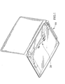
Fig. 1 is a perspective view of an electronic device including a battery and a locking mechanism in accordance with the present invention. -
Fig. 2 is another perspective view of the electronic device including the battery and the locking mechanism. -
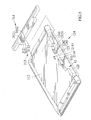
Fig. 3 is an exploded perspective view of the electronic device including the battery and the locking mechanism. -
Fig. 4 is another exploded perspective view of the electronic device including the battery and the locking mechanism. -
Fig. 5 is yet another exploded perspective view showing the battery disengaged from the electronic device. -
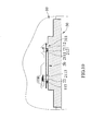
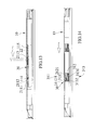
Fig. 6 is a cross-sectional view of the electronic device including the battery and the locking mechanism and shows the locking mechanism in one position. -
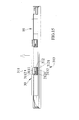
Fig. 7 is another cross-sectional view of the electronic device including the battery and the locking mechanism and shows the battery fastened to the electronic device by the locking mechanism. -
Fig. 8 is a fragmental, perspective view of the electronic device including the battery and the locking mechanism and shows an actuating member used for causing the operation of the locking mechanism, with the actuating member shown in phantom. -
Fig. 9 is a fragmental, cross-sectional view of the electronic device including the battery and the locking mechanism and shows the battery fastened to the electronic device by the battery locking mechanism as well as the locking mechanism in a first operating position. -
Fig. 10 is a partial enlarged view ofFig. 9 . -
Fig. 11 is another fragmental, perspective view of the electronic device including the battery and the locking mechanism and shows the locking mechanism operated to a position different than that shown inFig. 8 . -
Fig. 12 is a fragmental, cross-sectional view of the electronic device including the battery and the locking mechanism similar toFig. 10 but shows the locking mechanism in a second operating position and the battery adapted to be disengaged from the electronic device thereafter. -
Fig. 13 is an extended cross-sectional view ofFig. 6 , with the battery locking mechanism in the second operating position. -
Fig. 14 is an extended cross-sectional view ofFig. 7 , with the battery locking mechanism in the second operating position. -
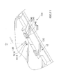
Fig. 15 is an extended cross-sectional view ofFig. 14 and shows the operation of removing the battery from the electronic device. - Referring to the drawings, an electronic device including a battery and a locking mechanism in accordance with the present invention includes a
base 10, alocking mechanism 20, abattery 30, and adisplay housing 40. - The
base 10 includes areceiving bay 11 and abattery bay 12. The receivingbay 11 includes an opening for allowing insertion of objects that are to be disposed on thereceiving bay 11. The objects at least include a system board, a processor, and a hard drive. Furthermore, thereceiving bay 11 includes aninner periphery 111, anouter periphery 112, and a throughslot 113 extending from theinner periphery 111 to theouter periphery 112. Thereceiving bay 11 further includes twoengaging members 114 as well as a joint 115 extending from theinner periphery 111. Eachengaging member 114 includes an inner thread formed thereon. Thejoint 115 is in the form of a ring. Thebattery bay 12 includes an opening for allowing insertion thebattery 30 and thebattery 30 is restrained in thebattery bay 12 when it is engaged with the electronic device. Furthermore, the battery bay 12 and thebattery 30 are of complement shapes to each other and thebattery 30 restrained in thebattery bay 12 includes an outer periphery flush with theouter periphery 112 of thereceiving bay 11. Moreover, thebattery bay 12 includes a periphery defining aninner periphery 121 and anouter periphery 122 and the inner andouter peripheries outer peripheries bay 11, respectively. A connectingedge 123 is defined from the periphery of thebattery bay 12 and protrudes in an upward direction from thereceiving bay 11. Further, two joiningends 124 are defined on the connectingedge 123 and each includes two opposingfirst end walls 1241, two opposingsecond end walls 1242 each extending from onefirst end wall 1241 to the otherfirst end wall 1241, and a throughhole 1243 delimited by the twofirst end walls 1241 as well as the twosecond end walls 1242. - The
locking mechanism 20 is operably movable between a first operating position to fasten thebattery 30 to the electronic device and a second operating position where thebattery 30 is adapted to be disengaged from the electronic device. Moreover, thelocking mechanism 20 includes a lockingmember 21 and anelastic element 22. The lockingmember 21 and theelastic element 22 are received in the receivingbay 11 of thebase 10. Furthermore, the lockingmember 21 is movable and includes a firstengaging edge 211 mounted on theinner periphery 111 of the receivingbay 11 and a secondengaging edge 212 protruding in an upward direction from the firstengaging edge 211. In addition, the firstengaging edge 211 includes twogrooves 2111 extending therethrough, and the twoengaging members 114 disposed to insert through the twogrooves 2111, respectively. Namely, each engaging member 14 has a cross-sectional size smaller than a width of therelated groove 2111 so as to extend through thegroove 2111. Likewise, the twogrooves 2111 are parallel to each other in that eachgroove 2111 extends longitudinally in the same direction. In the preferred embodiment, the twogrooves 2111 are not disposed coaxially. Further, twofasteners 2112 each includes a head with a cross sectional size greater than the width of any groove(s) 2111 are engaged with twoengaging members 114, respectively, for restraining the lockingmember 21 from disengagement from thebase 10. Eachfastener 2112 includes an outer thread formed thereon. In this regard, the engagingmembers 114 and thefasteners 2112 are in thread engagement. The firstengaging edge 211 further includes a joint 2113 in the form of a slit extending through the firstengaging edge 211. The joint 2113 and the joint 115 are cooperated to hold theelastic element 22. Namely, theelastic element 22 has twodistal ends 221, with onedistal end 221 hooked to the joint 115 and the otherdistal end 221 hooked to the joint 2113. Additionally, acutout 2114 is defined in the firstengaging edge 211 and extends therethrough. Thecutout 2114 includes the joint 115 extending therethrough, that is, the joint 115 will not interfere with the structure of the lockingmember 21. Likewise, thecutout 2114 receives theelastic element 22 and does not interfere it. As a result, theelastic element 22 will not interfere with the structure of the lockingmember 21. Specifically, theelastic element 22 extends longitudinally in a direction the same as a longitudinal length direction of thecutout 2114. Furthermore, thecutout 2114 is disposed adjacent and parallel to one of the twogrooves 2111. The firstengaging edge 211 yet further includes anoperation portion 2115 defined thereon for a user to operate thelocking mechanism 20. Theoperation portion 2115 is located within the receivingbay 11 and is exposed to outside of the receivingbay 11 throughslot 113. Also, theoperation portion 2115 is in the form of a recess. Further, a reinforcingstructure 2116 is defined on the firstengaging edge 211. The reinforcingstructure 2116 is in the form of a protrusion. In addition, the reinforcingstructure 2116 includes theoperation portion 2115 defined therein. - Furthermore, the second
engaging edge 212 of the lockingmember 21 includes two clutchingends 2121 defined thereon and extending through the two joiningends 124, respectively. Namely, each clutchingend 2121 extends through the joiningend 124 through the related throughhole 1243. In other words, each clutchingend 2121 has a cross-sectional size smaller than a cross-sectional size of the relegated throughhole 1243 so as to extend therethrough. In addition, each clutchingend 2121 of the lockingmember 21 is movable in the related throughhole 1243 upon the operational movement of thelocking mechanism 20. Moreover, each clutchingend 2121 is in the form of a protrusion and is partially received in thebattery bay 12. - As set forth, the
battery 30 is received in thebattery bay 12 and is restrained therein by thelocking mechanism 20. Namely, thebattery 30 includes two connectingends 31 defined thereon for engaging with the two clutchingends 2121, respectively. Each connectingend 31 includes first and second limitingedges battery 30 that faces the connectingedge 123 of thebattery bay 12, and achannel 313 delimited by the first and second limitingedges edge 311 has a shape of a L which includes afirst extension 3111 and asecond extension 3112 extending transverse to thefirst extension 3111 while the second limitingedge 312 is I shaped and extends longitudinally in a direction parallel to thefirst extension 3111. Thechannel 313 includes afirst section 3131 extending longitudinally in a direction parallel to either thefirst extension 3111 and the second limitingedge 312 and spacing them. Thechannel 313 further includes asecond section 3132 extending longitudinally in a direction parallel to thesecond extension 3112. In addition, each clutchingend 2121 is movable in thechannel 313 of the related connectingend 31 upon the operational movement of thelocking mechanism 20. As shown inFig. 7 , when thebattery 30 is restrained in thebattery bay 12 and is fastened to the electronic device, the clutching ends 2121 are received in thefirst section 3131 of thechannel 313 of the related connecting ends 31 individually and each is disposed between thefirst extension 3111 of the related first limitingedge 311 and the related second limitingedge 312, whereby thebattery 30 can not be disengaged from the electronic device. Likewise, when thebattery 30 is to be disengaged from the electronic device, an actuating member with an end which is adapted to be inserted through the throughslot 113 for engagement with theoperation portion 2115 is utilized to cause thelocking mechanism 20 to move from the first operating position to the second operating position thereof. As shown inFigs. 8 and11 , the actuating member is a pen, which is an instrument that is easily acquired. So when thelocking mechanism 20 is moved from the first operating position to the second operating position thereof, the lockingmember 21 is moved to a position such that the clutching ends 2121 are moved towards thesecond extension 3112 of the first limitingedge 311 of the related connecting ends 31 individually until each is disengaged from the related second limitingedge 312, as best shown inFig. 14 . Thebattery 30 is then adapted to be lifted off thebattery bay 12 because the clutching ends 2121 are adapted to disengage the respective connecting ends 31 of thebattery 30 through thesecond section 3132 of therelated channel 313, which has a width greater than a cross-sectional size of the related clutchingend 2121 so as to allow the clutchingend 2121 to pass therethrough, as shown inFig. 15 . In addition, when thelocking mechanism 20 is in the second operating position, theelastic element 22 is stretched. On the contrary, when a force that counteracts theelastic element 22 to operate thelocking mechanism 20 to the second operating position thereof is removed, thelocking mechanism 20 is automatically moved to the first operating position thereof via resilient force of theelastic element 22 in that theelastic element 22 is released from tension. - Furthermore, the
display housing 40 is pivotally connected to thebase 10, namely, thedisplay housing 40 is pivotal towards or away from the base 10 selectively. - In view of the forgoing, the
locking mechanism 20 will not suffer a problem of being activated inadvertently in that it is disposed within the receivingbay 11 of thebase 10. Additionally, the operation of thelocking mechanism 20 is easy in that user thereof just operates theoperation portion 2115 of the lockingmember 21 to cause thelocking mechanism 20 to move from the first operating position to the second operating position thereof. Furthermore, thelocking mechanism 20 is adapted to return from the second operating position to the first operating position thereof automatically under resilient force of theelastic element 22. - While the specific embodiment has been illustrated and described, numerous modifications come to mind without significantly departing from the spirit of invention and the scope of invention is only limited by the scope of accompanying claims.
Claims (15)
- An electronic device including a battery and a locking mechanism, comprising:a base (10) including a receiving bay (11) and a battery bay (12), with the receiving bay (11) including a first inner periphery (111), a first outer periphery (112) and a through slot (113) extending from the first inner periphery (111) to the first outer periphery (112), with the battery bay (12) including a periphery defining a second inner periphery (121) and a second outer periphery (122), with the second inner and outer peripheries (121, 122) extending from the first inner and outer peripheries (111, 112) respectively, with the battery bay (12) further including a connecting edge (123) defined from the periphery thereof, with the connecting edge (123) including a joining end (124) defined thereon;a locking mechanism (20) including a locking member (21) and an elastic element (22) received in the receiving bay (11), with the locking member (21) being movable and including a clutching end (2121) defined thereon and extending through the joining end (124) into the battery bay (12), with the elastic element (22) including one of two distal ends (221) joined to the receiving bay (11) and the other distal end (221) joined to the locking member (21), with the locking member (21) further including an operation portion (2115) defined thereon for a user to operate the locking mechanism (20), with the operation portion (2115) located within the receiving bay (11) and exposed to outside of the receiving bay (11) through slot (113);a battery (30) receivable and selectively restrained in the battery bay (12) by the locking mechanism (20) and including a connecting end (31) defined thereon for engaging with the clutching end (2121); andwherein the locking mechanism (20) is operably movable between a first operating position to fasten the battery (30) to the electronic device and a second operating position where the battery (30) is adapted to be disengaged from the electronic device, with the connecting end (31) of the battery (30) restrained by the clutching end (2121) of the locking member (21) when the locking mechanism (20) is in the first operating position, with the locking member (21) moved to a position such that the connecting end (31) of the battery (30) is unrestrained by the clutching end (2121) of the locking member (21) in order to be lifted off the battery bay (12) when the locking mechanism (20) is in the second operating position.
- The electronic device including the battery and the locking mechanism as claimed in claim 1, wherein the connecting end (31) of the battery (30) includes first and second limiting edges (311, 312) protruding from a surface of the battery that faces the connecting edge (123) of the battery bay (12), and a channel (313) delimited by the first and second limiting edges (311, 312).
- The electronic device including the battery and the locking mechanism as claimed in claim 2, wherein the first limiting edge (311) has a shape of a L which includes a first extension (3111) and a second extension (3112) extending transverse to the first extension (3111), and the second limiting edge (312) is I shaped and extends longitudinally in a direction parallel to the first extension (3111), and the channel (313) includes a first section (3131) extending longitudinally in a direction parallel to the first extension (3111) and the second limiting edge (312) and spacing the first extension (3111) and the second limiting edge (312), and the channel (313) further includes a second section (3132) extending longitudinally in a direction parallel to the second extension (3112).
- The electronic device including the battery and the locking mechanism as claimed in claim 3, wherein the clutching end (2121) of the locking member (21) is movable in the channel (313) of the connecting end (31) upon the operational movement of the locking mechanism (20).
- The electronic device including the battery and the locking mechanism as claimed in claim 4, wherein the clutching end (2121) is received in the first section (3131) of the channel (313) of the connecting end (31) and is disposed between the first extension (3111) of the first limiting edge (311) and the second limiting edge (312) when the locking mechanism (20) is in the first operating position.
- The electronic device including the battery and the locking mechanism as claimed in claim 1, wherein the operation portion (2115) of the locking member (21) is engaged by an actuating member that cause the locking mechanism (20) to move from the first operating position to the second operating position thereof, with the actuating member including an end adapted to be inserted through the through slot (113) for engagement with the operation portion (2115).
- The electronic device including the battery and the locking mechanism as claimed in claim 4, wherein the locking member (21) is moved to a position such that the clutching end (2121) is moved towards the second extension (3112) of the first limiting edge (311) of the connecting end (31) until the clutching end (2121) is disengaged from the related second limiting edge (312) when the locking mechanism (20) is in the second operating position.
- The electronic device including the battery and the locking mechanism as claimed in claim 4, wherein the second section (3132) of the channel (313) has a width greater than a cross-sectional size of the clutching end (2121) so as to allow the clutching end (2121) to pass therethrough.
- The electronic device including the battery and the locking mechanism as claimed in claim 1, wherein the elastic element (22) is stretched when the locking mechanism (20) is in the second operating position, and the elastic element (22) is relieved from force that counteract against when the locking mechanism (20) is in the first operating position, whereby the locking mechanism (20) is automatically moved to the first operating position thereof via resilient force of the elastic element (22).
- The electronic device including the battery and the locking mechanism as claimed in claim 1 further comprising a display housing (40) pivotally connected to the base (10).
- The electronic device including the battery and the locking mechanism as claimed in claim 1, wherein the receiving bay (11) includes an opening for allowing insertion of objects that are to be disposed on the receiving bay (11).
- The electronic device including the battery and the locking mechanism as claimed in claim 11, wherein the objects at least include system board, a processor, and a hard drive.
- The electronic device including the battery and the locking mechanism as claimed in claim 1, wherein the receiving bay (11) includes an engaging member (114) extending from the first inner periphery (111), and the locking member (20) includes a groove (2111) extending therethrough, with the engaging member (114) disposed to insert through the groove (2111), and a fastener (2112) including a head with a cross sectional size greater than a width of the groove (2111) is engaged with the engaging member (114) for restraining the locking member (21) from disengagement from the base (10).
- The electronic device including the battery and the locking mechanism as claimed in claim 13, wherein the engaging member (114) includes an inner thread formed thereon, and the fastener (2112) includes an outer thread formed thereon.
- The electronic device including the battery and the locking mechanism as claimed in claim 1, wherein the battery bay (12) and the battery (30) are of complement shapes to each other, and the battery (30) restrained in the battery bay (12) includes an outer periphery flush with the first outer periphery (112) of the receiving bay (11).
Applications Claiming Priority (1)
| Application Number | Priority Date | Filing Date | Title |
|---|---|---|---|
| TW099135954A TWI400597B (en) | 2010-10-21 | 2010-10-21 | Notebook with battery latch switch |
Publications (2)
| Publication Number | Publication Date |
|---|---|
| EP2445031A1 true EP2445031A1 (en) | 2012-04-25 |
| EP2445031B1 EP2445031B1 (en) | 2015-10-28 |
Family
ID=45525164
Family Applications (1)
| Application Number | Title | Priority Date | Filing Date |
|---|---|---|---|
| EP11162764.2A Active EP2445031B1 (en) | 2010-10-21 | 2011-04-18 | Electronic device including battery and locking mechanism for locking the battery to the electronic device |
Country Status (3)
| Country | Link |
|---|---|
| US (1) | US8422209B2 (en) |
| EP (1) | EP2445031B1 (en) |
| TW (1) | TWI400597B (en) |
Families Citing this family (8)
| Publication number | Priority date | Publication date | Assignee | Title |
|---|---|---|---|---|
| TWI412668B (en) * | 2011-05-09 | 2013-10-21 | Inventec Corp | Electronic device |
| TWI473360B (en) * | 2012-10-02 | 2015-02-11 | Inventec Corp | Electronic apparatus and movable fixing structure thereof |
| TWI461609B (en) * | 2012-10-03 | 2014-11-21 | Wistron Corp | Lock mechanism and related electronic device |
| CN103853286A (en) * | 2012-12-07 | 2014-06-11 | 鸿富锦精密工业(深圳)有限公司 | Battery module fixing device |
| CN104427016A (en) * | 2013-08-22 | 2015-03-18 | 中兴通讯股份有限公司 | Intelligent terminal |
| US10212835B1 (en) * | 2017-12-22 | 2019-02-19 | Bose Corporation | Device with latched battery cavity |
| USD914673S1 (en) * | 2018-06-13 | 2021-03-30 | Lenovo (Beijing) Co., Ltd. | Laptop computer |
| USD938413S1 (en) * | 2019-05-31 | 2021-12-14 | Lenovo (Beijing) Co., Ltd. | Laptop computer |
Citations (3)
| Publication number | Priority date | Publication date | Assignee | Title |
|---|---|---|---|---|
| GB2303018A (en) * | 1995-06-30 | 1997-02-05 | Nec Corp | Battery case mounting mechanism incorporates electrical contacts |
| US6051334A (en) | 1997-05-29 | 2000-04-18 | Fujitsu Limited | Battery lock mechanism for portable device |
| US20070072485A1 (en) * | 2005-09-23 | 2007-03-29 | Ke-Cheng Lin | Battery latch mechanism |
Family Cites Families (2)
| Publication number | Priority date | Publication date | Assignee | Title |
|---|---|---|---|---|
| JP2005157789A (en) * | 2003-11-26 | 2005-06-16 | Toshiba Corp | Electronic device |
| JP2010157442A (en) * | 2008-12-26 | 2010-07-15 | Sony Corp | Electronic apparatus, and battery pack |
-
2010
- 2010-10-21 TW TW099135954A patent/TWI400597B/en active
-
2011
- 2011-03-30 US US13/075,230 patent/US8422209B2/en active Active
- 2011-04-18 EP EP11162764.2A patent/EP2445031B1/en active Active
Patent Citations (4)
| Publication number | Priority date | Publication date | Assignee | Title |
|---|---|---|---|---|
| GB2303018A (en) * | 1995-06-30 | 1997-02-05 | Nec Corp | Battery case mounting mechanism incorporates electrical contacts |
| US6051334A (en) | 1997-05-29 | 2000-04-18 | Fujitsu Limited | Battery lock mechanism for portable device |
| US6302454B1 (en) * | 1997-05-29 | 2001-10-16 | Fujitsu Limited | Battery lock mechanism for portable device |
| US20070072485A1 (en) * | 2005-09-23 | 2007-03-29 | Ke-Cheng Lin | Battery latch mechanism |
Also Published As
| Publication number | Publication date |
|---|---|
| US20120099252A1 (en) | 2012-04-26 |
| EP2445031B1 (en) | 2015-10-28 |
| US8422209B2 (en) | 2013-04-16 |
| TWI400597B (en) | 2013-07-01 |
| TW201217941A (en) | 2012-05-01 |
Similar Documents
| Publication | Publication Date | Title |
|---|---|---|
| EP2445031B1 (en) | Electronic device including battery and locking mechanism for locking the battery to the electronic device | |
| US7423869B2 (en) | Hard disk drawing device | |
| JP5378251B2 (en) | clip | |
| US8411429B2 (en) | Mounting apparatus for disk drive | |
| US7492576B2 (en) | Computer with a case member mounting structure | |
| US9918523B2 (en) | Buckle assembly | |
| US8011633B2 (en) | Hook structure | |
| EP1840701A2 (en) | Computer with a case member mounting structure | |
| US20060209501A1 (en) | Computer enclosure | |
| US20110017894A1 (en) | Mounting mechanism for retaining slide rail to chassis | |
| US20050023943A1 (en) | Computer enclosure with latch device | |
| US20080239646A1 (en) | Bezel mounting assembly | |
| US20040214077A1 (en) | Battery locking apparatus for electronic device | |
| US20160230804A1 (en) | Snap Hook | |
| TW202026800A (en) | Fixing mechanism and related electronic apparatus | |
| US6507491B1 (en) | Pull/latch type fixing device for heat-radiating fin body | |
| US7322572B1 (en) | Spring-biased mechanism for quickly fastening slide bar and fixed jaw carrier of vise | |
| US20090134636A1 (en) | Latch mechanism | |
| WO2018008597A1 (en) | Lock device | |
| CN108153387A (en) | Cabinet panel installing mechanism | |
| US20110115348A1 (en) | Locking device and electronic enclosure using same | |
| JP2011103714A (en) | Band clip | |
| TW201328492A (en) | Electronic device | |
| US7609516B2 (en) | Computer enclosure with removable bezel | |
| TWI604442B (en) | Reciprocator-type quick-releasing mechanism |
Legal Events
| Date | Code | Title | Description |
|---|---|---|---|
| AK | Designated contracting states |
Kind code of ref document: A1 Designated state(s): AL AT BE BG CH CY CZ DE DK EE ES FI FR GB GR HR HU IE IS IT LI LT LU LV MC MK MT NL NO PL PT RO RS SE SI SK SM TR |
|
| AX | Request for extension of the european patent |
Extension state: BA ME |
|
| PUAI | Public reference made under article 153(3) epc to a published international application that has entered the european phase |
Free format text: ORIGINAL CODE: 0009012 |
|
| 17P | Request for examination filed |
Effective date: 20120828 |
|
| GRAP | Despatch of communication of intention to grant a patent |
Free format text: ORIGINAL CODE: EPIDOSNIGR1 |
|
| INTG | Intention to grant announced |
Effective date: 20150515 |
|
| GRAS | Grant fee paid |
Free format text: ORIGINAL CODE: EPIDOSNIGR3 |
|
| GRAA | (expected) grant |
Free format text: ORIGINAL CODE: 0009210 |
|
| AK | Designated contracting states |
Kind code of ref document: B1 Designated state(s): AL AT BE BG CH CY CZ DE DK EE ES FI FR GB GR HR HU IE IS IT LI LT LU LV MC MK MT NL NO PL PT RO RS SE SI SK SM TR |
|
| REG | Reference to a national code |
Ref country code: GB Ref legal event code: FG4D |
|
| REG | Reference to a national code |
Ref country code: CH Ref legal event code: EP |
|
| REG | Reference to a national code |
Ref country code: AT Ref legal event code: REF Ref document number: 758366 Country of ref document: AT Kind code of ref document: T Effective date: 20151115 |
|
| REG | Reference to a national code |
Ref country code: IE Ref legal event code: FG4D |
|
| REG | Reference to a national code |
Ref country code: DE Ref legal event code: R096 Ref document number: 602011020945 Country of ref document: DE |
|
| REG | Reference to a national code |
Ref country code: LT Ref legal event code: MG4D |
|
| REG | Reference to a national code |
Ref country code: NL Ref legal event code: MP Effective date: 20151028 |
|
| REG | Reference to a national code |
Ref country code: AT Ref legal event code: MK05 Ref document number: 758366 Country of ref document: AT Kind code of ref document: T Effective date: 20151028 |
|
| PG25 | Lapsed in a contracting state [announced via postgrant information from national office to epo] |
Ref country code: IT Free format text: LAPSE BECAUSE OF FAILURE TO SUBMIT A TRANSLATION OF THE DESCRIPTION OR TO PAY THE FEE WITHIN THE PRESCRIBED TIME-LIMIT Effective date: 20151028 Ref country code: LT Free format text: LAPSE BECAUSE OF FAILURE TO SUBMIT A TRANSLATION OF THE DESCRIPTION OR TO PAY THE FEE WITHIN THE PRESCRIBED TIME-LIMIT Effective date: 20151028 Ref country code: NL Free format text: LAPSE BECAUSE OF FAILURE TO SUBMIT A TRANSLATION OF THE DESCRIPTION OR TO PAY THE FEE WITHIN THE PRESCRIBED TIME-LIMIT Effective date: 20151028 Ref country code: HR Free format text: LAPSE BECAUSE OF FAILURE TO SUBMIT A TRANSLATION OF THE DESCRIPTION OR TO PAY THE FEE WITHIN THE PRESCRIBED TIME-LIMIT Effective date: 20151028 Ref country code: IS Free format text: LAPSE BECAUSE OF FAILURE TO SUBMIT A TRANSLATION OF THE DESCRIPTION OR TO PAY THE FEE WITHIN THE PRESCRIBED TIME-LIMIT Effective date: 20160228 Ref country code: ES Free format text: LAPSE BECAUSE OF FAILURE TO SUBMIT A TRANSLATION OF THE DESCRIPTION OR TO PAY THE FEE WITHIN THE PRESCRIBED TIME-LIMIT Effective date: 20151028 Ref country code: NO Free format text: LAPSE BECAUSE OF FAILURE TO SUBMIT A TRANSLATION OF THE DESCRIPTION OR TO PAY THE FEE WITHIN THE PRESCRIBED TIME-LIMIT Effective date: 20160128 |
|
| PG25 | Lapsed in a contracting state [announced via postgrant information from national office to epo] |
Ref country code: PL Free format text: LAPSE BECAUSE OF FAILURE TO SUBMIT A TRANSLATION OF THE DESCRIPTION OR TO PAY THE FEE WITHIN THE PRESCRIBED TIME-LIMIT Effective date: 20151028 Ref country code: FI Free format text: LAPSE BECAUSE OF FAILURE TO SUBMIT A TRANSLATION OF THE DESCRIPTION OR TO PAY THE FEE WITHIN THE PRESCRIBED TIME-LIMIT Effective date: 20151028 Ref country code: RS Free format text: LAPSE BECAUSE OF FAILURE TO SUBMIT A TRANSLATION OF THE DESCRIPTION OR TO PAY THE FEE WITHIN THE PRESCRIBED TIME-LIMIT Effective date: 20151028 Ref country code: GR Free format text: LAPSE BECAUSE OF FAILURE TO SUBMIT A TRANSLATION OF THE DESCRIPTION OR TO PAY THE FEE WITHIN THE PRESCRIBED TIME-LIMIT Effective date: 20160129 Ref country code: PT Free format text: LAPSE BECAUSE OF FAILURE TO SUBMIT A TRANSLATION OF THE DESCRIPTION OR TO PAY THE FEE WITHIN THE PRESCRIBED TIME-LIMIT Effective date: 20160229 Ref country code: AT Free format text: LAPSE BECAUSE OF FAILURE TO SUBMIT A TRANSLATION OF THE DESCRIPTION OR TO PAY THE FEE WITHIN THE PRESCRIBED TIME-LIMIT Effective date: 20151028 Ref country code: SE Free format text: LAPSE BECAUSE OF FAILURE TO SUBMIT A TRANSLATION OF THE DESCRIPTION OR TO PAY THE FEE WITHIN THE PRESCRIBED TIME-LIMIT Effective date: 20151028 Ref country code: LV Free format text: LAPSE BECAUSE OF FAILURE TO SUBMIT A TRANSLATION OF THE DESCRIPTION OR TO PAY THE FEE WITHIN THE PRESCRIBED TIME-LIMIT Effective date: 20151028 |
|
| PG25 | Lapsed in a contracting state [announced via postgrant information from national office to epo] |
Ref country code: CZ Free format text: LAPSE BECAUSE OF FAILURE TO SUBMIT A TRANSLATION OF THE DESCRIPTION OR TO PAY THE FEE WITHIN THE PRESCRIBED TIME-LIMIT Effective date: 20151028 |
|
| REG | Reference to a national code |
Ref country code: DE Ref legal event code: R097 Ref document number: 602011020945 Country of ref document: DE |
|
| PG25 | Lapsed in a contracting state [announced via postgrant information from national office to epo] |
Ref country code: DK Free format text: LAPSE BECAUSE OF FAILURE TO SUBMIT A TRANSLATION OF THE DESCRIPTION OR TO PAY THE FEE WITHIN THE PRESCRIBED TIME-LIMIT Effective date: 20151028 Ref country code: BE Free format text: LAPSE BECAUSE OF NON-PAYMENT OF DUE FEES Effective date: 20160430 Ref country code: RO Free format text: LAPSE BECAUSE OF FAILURE TO SUBMIT A TRANSLATION OF THE DESCRIPTION OR TO PAY THE FEE WITHIN THE PRESCRIBED TIME-LIMIT Effective date: 20151028 Ref country code: SM Free format text: LAPSE BECAUSE OF FAILURE TO SUBMIT A TRANSLATION OF THE DESCRIPTION OR TO PAY THE FEE WITHIN THE PRESCRIBED TIME-LIMIT Effective date: 20151028 Ref country code: SK Free format text: LAPSE BECAUSE OF FAILURE TO SUBMIT A TRANSLATION OF THE DESCRIPTION OR TO PAY THE FEE WITHIN THE PRESCRIBED TIME-LIMIT Effective date: 20151028 Ref country code: EE Free format text: LAPSE BECAUSE OF FAILURE TO SUBMIT A TRANSLATION OF THE DESCRIPTION OR TO PAY THE FEE WITHIN THE PRESCRIBED TIME-LIMIT Effective date: 20151028 |
|
| PLBE | No opposition filed within time limit |
Free format text: ORIGINAL CODE: 0009261 |
|
| STAA | Information on the status of an ep patent application or granted ep patent |
Free format text: STATUS: NO OPPOSITION FILED WITHIN TIME LIMIT |
|
| 26N | No opposition filed |
Effective date: 20160729 |
|
| PG25 | Lapsed in a contracting state [announced via postgrant information from national office to epo] |
Ref country code: SI Free format text: LAPSE BECAUSE OF FAILURE TO SUBMIT A TRANSLATION OF THE DESCRIPTION OR TO PAY THE FEE WITHIN THE PRESCRIBED TIME-LIMIT Effective date: 20151028 |
|
| REG | Reference to a national code |
Ref country code: CH Ref legal event code: PL |
|
| GBPC | Gb: european patent ceased through non-payment of renewal fee |
Effective date: 20160418 |
|
| PG25 | Lapsed in a contracting state [announced via postgrant information from national office to epo] |
Ref country code: BE Free format text: LAPSE BECAUSE OF FAILURE TO SUBMIT A TRANSLATION OF THE DESCRIPTION OR TO PAY THE FEE WITHIN THE PRESCRIBED TIME-LIMIT Effective date: 20151028 Ref country code: LU Free format text: LAPSE BECAUSE OF FAILURE TO SUBMIT A TRANSLATION OF THE DESCRIPTION OR TO PAY THE FEE WITHIN THE PRESCRIBED TIME-LIMIT Effective date: 20160418 |
|
| REG | Reference to a national code |
Ref country code: IE Ref legal event code: MM4A |
|
| REG | Reference to a national code |
Ref country code: FR Ref legal event code: ST Effective date: 20161230 |
|
| PG25 | Lapsed in a contracting state [announced via postgrant information from national office to epo] |
Ref country code: CH Free format text: LAPSE BECAUSE OF NON-PAYMENT OF DUE FEES Effective date: 20160430 Ref country code: LI Free format text: LAPSE BECAUSE OF NON-PAYMENT OF DUE FEES Effective date: 20160430 Ref country code: FR Free format text: LAPSE BECAUSE OF NON-PAYMENT OF DUE FEES Effective date: 20160502 Ref country code: GB Free format text: LAPSE BECAUSE OF NON-PAYMENT OF DUE FEES Effective date: 20160418 |
|
| PG25 | Lapsed in a contracting state [announced via postgrant information from national office to epo] |
Ref country code: IE Free format text: LAPSE BECAUSE OF NON-PAYMENT OF DUE FEES Effective date: 20160418 |
|
| PG25 | Lapsed in a contracting state [announced via postgrant information from national office to epo] |
Ref country code: CY Free format text: LAPSE BECAUSE OF FAILURE TO SUBMIT A TRANSLATION OF THE DESCRIPTION OR TO PAY THE FEE WITHIN THE PRESCRIBED TIME-LIMIT Effective date: 20151028 Ref country code: HU Free format text: LAPSE BECAUSE OF FAILURE TO SUBMIT A TRANSLATION OF THE DESCRIPTION OR TO PAY THE FEE WITHIN THE PRESCRIBED TIME-LIMIT; INVALID AB INITIO Effective date: 20110418 |
|
| PG25 | Lapsed in a contracting state [announced via postgrant information from national office to epo] |
Ref country code: MT Free format text: LAPSE BECAUSE OF NON-PAYMENT OF DUE FEES Effective date: 20160430 Ref country code: MC Free format text: LAPSE BECAUSE OF FAILURE TO SUBMIT A TRANSLATION OF THE DESCRIPTION OR TO PAY THE FEE WITHIN THE PRESCRIBED TIME-LIMIT Effective date: 20151028 Ref country code: TR Free format text: LAPSE BECAUSE OF FAILURE TO SUBMIT A TRANSLATION OF THE DESCRIPTION OR TO PAY THE FEE WITHIN THE PRESCRIBED TIME-LIMIT Effective date: 20151028 Ref country code: MK Free format text: LAPSE BECAUSE OF FAILURE TO SUBMIT A TRANSLATION OF THE DESCRIPTION OR TO PAY THE FEE WITHIN THE PRESCRIBED TIME-LIMIT Effective date: 20151028 |
|
| PG25 | Lapsed in a contracting state [announced via postgrant information from national office to epo] |
Ref country code: BG Free format text: LAPSE BECAUSE OF FAILURE TO SUBMIT A TRANSLATION OF THE DESCRIPTION OR TO PAY THE FEE WITHIN THE PRESCRIBED TIME-LIMIT Effective date: 20151028 |
|
| PG25 | Lapsed in a contracting state [announced via postgrant information from national office to epo] |
Ref country code: AL Free format text: LAPSE BECAUSE OF FAILURE TO SUBMIT A TRANSLATION OF THE DESCRIPTION OR TO PAY THE FEE WITHIN THE PRESCRIBED TIME-LIMIT Effective date: 20151028 |
|
| REG | Reference to a national code |
Ref country code: DE Ref legal event code: R079 Ref document number: 602011020945 Country of ref document: DE Free format text: PREVIOUS MAIN CLASS: H01M0002020000 Ipc: H01M0050100000 |
|
| PGFP | Annual fee paid to national office [announced via postgrant information from national office to epo] |
Ref country code: DE Payment date: 20230321 Year of fee payment: 13 |