EP2420448A1 - Absorbing dome for a radiating collector tube - Google Patents
Absorbing dome for a radiating collector tube Download PDFInfo
- Publication number
- EP2420448A1 EP2420448A1 EP11177318A EP11177318A EP2420448A1 EP 2420448 A1 EP2420448 A1 EP 2420448A1 EP 11177318 A EP11177318 A EP 11177318A EP 11177318 A EP11177318 A EP 11177318A EP 2420448 A1 EP2420448 A1 EP 2420448A1
- Authority
- EP
- European Patent Office
- Prior art keywords
- screen
- absorbent
- equipment
- radiation
- satellite
- Prior art date
- Legal status (The legal status is an assumption and is not a legal conclusion. Google has not performed a legal analysis and makes no representation as to the accuracy of the status listed.)
- Granted
Links
- 238000000034 method Methods 0.000 claims abstract description 7
- 239000004020 conductor Substances 0.000 claims abstract description 3
- 230000005855 radiation Effects 0.000 claims description 52
- 230000002745 absorbent Effects 0.000 claims description 51
- 239000002250 absorbent Substances 0.000 claims description 51
- 238000000576 coating method Methods 0.000 claims description 24
- 239000011248 coating agent Substances 0.000 claims description 23
- 238000009413 insulation Methods 0.000 claims description 14
- 239000012530 fluid Substances 0.000 claims description 12
- 238000002329 infrared spectrum Methods 0.000 claims description 10
- 230000004907 flux Effects 0.000 claims description 5
- 238000012360 testing method Methods 0.000 claims description 3
- 230000032258 transport Effects 0.000 abstract description 6
- PXHVJJICTQNCMI-UHFFFAOYSA-N Nickel Chemical compound [Ni] PXHVJJICTQNCMI-UHFFFAOYSA-N 0.000 description 7
- 206010011906 Death Diseases 0.000 description 6
- RTAQQCXQSZGOHL-UHFFFAOYSA-N Titanium Chemical compound [Ti] RTAQQCXQSZGOHL-UHFFFAOYSA-N 0.000 description 6
- 230000017525 heat dissipation Effects 0.000 description 6
- 238000010438 heat treatment Methods 0.000 description 6
- 239000010936 titanium Substances 0.000 description 6
- 229910052719 titanium Inorganic materials 0.000 description 6
- 230000008901 benefit Effects 0.000 description 4
- 238000001816 cooling Methods 0.000 description 4
- 239000000463 material Substances 0.000 description 4
- 229910052782 aluminium Inorganic materials 0.000 description 3
- XAGFODPZIPBFFR-UHFFFAOYSA-N aluminium Chemical compound [Al] XAGFODPZIPBFFR-UHFFFAOYSA-N 0.000 description 3
- 238000010586 diagram Methods 0.000 description 3
- 230000007613 environmental effect Effects 0.000 description 3
- 230000000750 progressive effect Effects 0.000 description 3
- 239000007787 solid Substances 0.000 description 3
- 239000006096 absorbing agent Substances 0.000 description 2
- 230000004308 accommodation Effects 0.000 description 2
- 230000006378 damage Effects 0.000 description 2
- 238000005516 engineering process Methods 0.000 description 2
- 230000006870 function Effects 0.000 description 2
- 230000001965 increasing effect Effects 0.000 description 2
- 238000012986 modification Methods 0.000 description 2
- 230000004048 modification Effects 0.000 description 2
- 229910001120 nichrome Inorganic materials 0.000 description 2
- 229910052759 nickel Inorganic materials 0.000 description 2
- 230000003647 oxidation Effects 0.000 description 2
- 238000007254 oxidation reaction Methods 0.000 description 2
- 229920003223 poly(pyromellitimide-1,4-diphenyl ether) Polymers 0.000 description 2
- 230000009467 reduction Effects 0.000 description 2
- 230000035882 stress Effects 0.000 description 2
- 241001080024 Telles Species 0.000 description 1
- 240000008042 Zea mays Species 0.000 description 1
- 238000010521 absorption reaction Methods 0.000 description 1
- 230000004913 activation Effects 0.000 description 1
- 239000000853 adhesive Substances 0.000 description 1
- 230000001070 adhesive effect Effects 0.000 description 1
- 230000003321 amplification Effects 0.000 description 1
- 238000007743 anodising Methods 0.000 description 1
- 239000000919 ceramic Substances 0.000 description 1
- 238000004891 communication Methods 0.000 description 1
- 239000002131 composite material Substances 0.000 description 1
- 230000001276 controlling effect Effects 0.000 description 1
- 230000008878 coupling Effects 0.000 description 1
- 238000010168 coupling process Methods 0.000 description 1
- 238000005859 coupling reaction Methods 0.000 description 1
- 238000007872 degassing Methods 0.000 description 1
- 238000000151 deposition Methods 0.000 description 1
- 238000013461 design Methods 0.000 description 1
- 238000011161 development Methods 0.000 description 1
- 238000001704 evaporation Methods 0.000 description 1
- 230000008020 evaporation Effects 0.000 description 1
- 230000000763 evoking effect Effects 0.000 description 1
- 239000004744 fabric Substances 0.000 description 1
- 239000000446 fuel Substances 0.000 description 1
- 239000011521 glass Substances 0.000 description 1
- 229910002804 graphite Inorganic materials 0.000 description 1
- 239000010439 graphite Substances 0.000 description 1
- -1 graphite compound Chemical class 0.000 description 1
- 230000008642 heat stress Effects 0.000 description 1
- 238000002513 implantation Methods 0.000 description 1
- 238000009434 installation Methods 0.000 description 1
- 239000012212 insulator Substances 0.000 description 1
- 238000002955 isolation Methods 0.000 description 1
- 239000007769 metal material Substances 0.000 description 1
- 238000003199 nucleic acid amplification method Methods 0.000 description 1
- 230000003287 optical effect Effects 0.000 description 1
- 238000005457 optimization Methods 0.000 description 1
- 239000002245 particle Substances 0.000 description 1
- 238000004382 potting Methods 0.000 description 1
- 238000012797 qualification Methods 0.000 description 1
- 230000001105 regulatory effect Effects 0.000 description 1
- 238000004088 simulation Methods 0.000 description 1
- 238000004513 sizing Methods 0.000 description 1
- 238000001228 spectrum Methods 0.000 description 1
- 238000005382 thermal cycling Methods 0.000 description 1
- 150000003608 titanium Chemical class 0.000 description 1
- 238000009281 ultraviolet germicidal irradiation Methods 0.000 description 1
Images


Classifications
-
- B—PERFORMING OPERATIONS; TRANSPORTING
- B64—AIRCRAFT; AVIATION; COSMONAUTICS
- B64G—COSMONAUTICS; VEHICLES OR EQUIPMENT THEREFOR
- B64G1/00—Cosmonautic vehicles
- B64G1/22—Parts of, or equipment specially adapted for fitting in or to, cosmonautic vehicles
- B64G1/46—Arrangements or adaptations of devices for control of environment or living conditions
- B64G1/50—Arrangements or adaptations of devices for control of environment or living conditions for temperature control
- B64G1/503—Radiator panels
-
- B—PERFORMING OPERATIONS; TRANSPORTING
- B64—AIRCRAFT; AVIATION; COSMONAUTICS
- B64G—COSMONAUTICS; VEHICLES OR EQUIPMENT THEREFOR
- B64G1/00—Cosmonautic vehicles
- B64G1/22—Parts of, or equipment specially adapted for fitting in or to, cosmonautic vehicles
- B64G1/52—Protection, safety or emergency devices; Survival aids
- B64G1/58—Thermal protection, e.g. heat shields
-
- H—ELECTRICITY
- H01—ELECTRIC ELEMENTS
- H01J—ELECTRIC DISCHARGE TUBES OR DISCHARGE LAMPS
- H01J23/00—Details of transit-time tubes of the types covered by group H01J25/00
- H01J23/02—Electrodes; Magnetic control means; Screens
- H01J23/027—Collectors
- H01J23/033—Collector cooling devices
-
- H—ELECTRICITY
- H01—ELECTRIC ELEMENTS
- H01J—ELECTRIC DISCHARGE TUBES OR DISCHARGE LAMPS
- H01J25/00—Transit-time tubes, e.g. klystrons, travelling-wave tubes, magnetrons
- H01J25/34—Travelling-wave tubes; Tubes in which a travelling wave is simulated at spaced gaps
Definitions
- the invention relates to the field of thermal control. It relates more particularly to the active thermal control of a device in a space environment, and aims in particular at an application in the case of a telecommunications satellite stabilized on three axes, and equipped with traveling wave tubes with radiant collector.
- the payload often includes traveling wave tubes ("TOP" or “TWT” for Traveling-Wave Tube, in English), intended for amplification of the signal to be transmitted with a very low background noise.
- TOP traveling wave tubes
- TWT Traveling-Wave Tube
- the collector of these traveling-wave tubes with radiating collector operates frequently at a temperature of about 200 ° C., whereas the tube itself is brought to a few tens of degrees C.
- the heat released on a satellite The current telecommunications reach several kilowatts, and it is clear that the heat dissipation capacity is then a sizing element of the power of the payload.
- the "hot” case is defined as the situation in which a radiating tube is subjected to solar radiation, even though the radiating tube is in operation and therefore produces a significant heat to dissipate.
- the "cold” case is defined as the case where the radiant collector is in the shadow of the satellite. We understand that the temperature difference between these two cases is in tens of degrees.
- This principle of the collector tube radiator (TCR), known per se, is illustrated schematically on the figure 1 .
- This figure highlights the internal zone 1 to the satellite, delimited in a simplified manner by a floor 2 (which is actually a north or south face of the satellite) and a wall 3, which is for example oriented East or West relative to the sun .
- the heat dissipation is mainly by conduction.
- the outer zone 4 to the satellite the heat dissipation is by radiation.
- the satellite comprises a set of progressive wave tubes 5 of a type known per se.
- Each traveling wave tube 5 comprises a signal input 10 to be amplified, an amplified signal output 11, and a collector 6, which passes through a wall 3 of the satellite and supports a finned radiator 7 disposed outside the satellite.
- the fins typically eight in number, are generally of equal length and fit in a circle.
- the role of the finned radiator 7 is to radiate about 60% of the heat produced by the Progressive Wave Tube to the cold source space. The rest of the heat, about 40%, is dissipated in the wall supporting the tube (see figure 2 ) .
- the finned radiator 7 receives radiation emitted by the sun or another external radiation source, and transmits it by conduction to the collector 6 of the traveling wave tube 5.
- An insulating multilayer protection 9 envelopes and isolates the satellite, reducing the input of solar radiation or radiation generated by the finned radiator in the satellite.
- Such a device is called Radiative Cooled Traveling-Wave Tube (RCTWT).
- RCTWT Radiative Cooled Traveling-Wave Tube
- Such devices are conventionally installed on the edges near the north and south faces, so that the radiant collectors have a view factor to the largest possible space (the solid angle under which the equipment can emit radiation without receiving reflected radiation) in an area with low sunlight.
- the finned radiators 7 of the tubes 5 located between other tubes have their radiation zone towards the space masked by the radiators. 7 fins that surround them, which reduces their effectiveness.
- the spacing between the fin coolers may have to be increased, which implies increasing the pitch between the traveling wave tubes within the payload.
- the present invention therefore aims to overcome the aforementioned drawbacks by proposing a new satellite payload thermal control device.
- a sensor disposed around an equipment on board a satellite receives solar radiation in the visible band and a remote radiator discharges this energy in the form of infrared radiation, so as to prevent the solar radiation received by the sensor from being reflected back to the equipment. In this way, the temperature of the equipment is reduced.
- the radiation emitting means at a distance from the absorbing screen, and therefore typically in an area not subject to external radiation, or not supporting equipment sensitive to said radiation.
- the second emission surface radiates towards the outside of the machine either directly or indirectly after reflection on a coating (for example of the "MLI" multilayer insulating coating) of the outer wall of the vehicle.
- the absorbing screen is made of a very heat-conducting material, and has, on at least a portion of its posterior face, adapted to be oriented towards the wall of the machine, a high emissivity in the infrared spectrum, typically greater than or equal to 0.7.
- the absorbent screen has a generally concave shape adapted to be arranged around the outer part of the equipment.
- the absorbent screen comprises a first substantially flat surface and adapted to be arranged parallel to the satellite wall, provided with two lateral flanges inclined at an angle of about 20 to 50 ° with respect to said first surface.
- the absorbent screen comprises a flat surface, the central portion of said flat surface receiving an absorbent coating having a high absorption of solar radiation, the edges of this surface receiving a highly emissive coating in the infrared range
- the absorbent screen comprises fixing means and conductive insulation so as to dispose substantially perpendicular to the main axis of the outer portion of the equipment.
- the absorbent screen is composed of several parts adapted to be assembled around the outer part of the equipment, when it is already installed. on a craft.
- the absorbent screen is a multilayer insulating high temperature absorbent insulating element comprising a sheet of high solar radiation absorptivity and low emissivity ⁇ IR in the infrared spectrum. This arrangement corresponds to an inexpensive implementation of the device
- the invention in another aspect, relates to a satellite, comprising at least one thermal control device as described above.
- the invention relates to a method of thermal management of a satellite as described, comprising a step of installing at least one absorbing screen on the outer part of at least one equipment, according to their maximum temperature estimated or measured during a test.
- the invention relates to a method of thermal management of a satellite as described, comprising a step of installing at least one absorbing screen on at least one radiant collector tube radiator, according to their estimated maximum temperature.
- the method comprises a step of installing at least one absorbent screen on at least one tube radiator disposed at the center of East or West faces, or at least one radiator disposed between other radiators.
- the invention is intended to be used especially in the context of a spacecraft, in the present example in no way limiting a satellite orbiting the Earth.
- a spacecraft in the present example in no way limiting a satellite orbiting the Earth.
- the invention also applies to any other type of support placed in the vacuum and intended to dissipate its heat purely by radiation.
- infrared spectrum is defined by the wavelength band lying approximately between 780 nm and 100 ⁇ m, and the solar spectrum by the band between 10 and 780 nm.
- the invention is here described in an application to a tube with radiant collector (radiative tube), as described above with reference to the Figures 1 and 2 , provided with a radiator external to the satellite, and arranged within the satellite so as to determine a free space, at least a few millimeters thick, between the edge of the radiator closest to the wall 3 of the satellite, and multilayer insulation cover 9.
- a tube with radiant collector radiant tube
- the thermal control device comprises an absorbent screen 13 interposed between one or more radiators with fins 7 of radiating collectors and the multilayer insulating protection 9. It is understood that this absorbing screen is located behind the radiators to fins 7, vis-à-vis the space. In this way, it does not interfere with the radiation emitted by the finned radiator 7 from the radiant collector to the space. On the other hand, it considerably reduces the factor of view of the protection multilayer insulation 9 by the finned radiator 7 of the radiant collector, thereby reducing the radiation that may be emitted by the finned radiator 7 to said protection 9.
- the absorbent screen has a generally concave shape around the finned radiator 7 of the radiant collector 6.
- the absorbent screen 13 comprises, in the present example, a first surface 14, rectangular, substantially flat and parallel to the wall 3 of the satellite , having two lateral flanges 16, 17 inclined at an angle of approximately 30 to 45 ° with respect to said first surface 14.
- the first surface 14 has a recess (not visible on the figure 4 ), at the axis of the radiant collector, to allow the passage thereof.
- this recess is of rectangular shape and of dimensions just greater than those of the radiant collector 6. It is understood that the radiant collector 6 is not in direct contact with the absorbent screen 13 as described, to avoid a thermal conduction between them.
- the width / 1 of the first surface 14 is greater than the wingspan of the radiator 7, and here about forty centimeters, for a length that depends on the number of radiant collectors concerned by the device. For information only, the length of the first surface may thus be of the order of 120 centimeters if the absorbent screen 13 is to be arranged behind five radiant collectors.
- the width / 2 of the lateral flanges is here of the order of ten centimeters, with a length equal to that of the first surface 14 of the absorbent screen 13.
- the screen comprises a first disc-shaped surface 14, surrounded by a frustoconical inclined edge 16.
- the absorbent screen 13 is made of a light material that is very conducive to heat, adapted to withstand a temperature of more than 200 ° C. It is in the present example made of aluminum, according to a technique known to those skilled in the art. In an alternative embodiment, the absorbent screen 13 is made of high conductivity composite material.
- the absorbent screen 13 is here made in two substantially symmetrical parts, assembled in place, for example by screwing or other known technique.
- the back side of the absorbent screen 13 receives, in the present example, a highly emissive coating, for example of the type known under the trade name Kepla coat (trademark) which is a black coating with plasma oxidation.
- a highly emissive coating for example of the type known under the trade name Kepla coat (trademark) which is a black coating with plasma oxidation.
- the absorbing screen 13 is intended to be placed in orbit with the satellite, and must therefore be compatible with the space environment. Its mechanical and geometrical characteristics are therefore adapted to take into account the constraints at launch and during spaceflight: resistance to degassing, thermal cycling, electrostatic charges, UV irradiation, aerothermal flow at launch, mechanical stresses at launch and in flight (particles).
- the absorbent screen 13 is secured to the walls 2, 3 of the satellite by means known per se, respecting a thermal decoupling between the absorbing screen 13 and the satellite, and the device comprises a grounding of the absorbing screen 13 .
- Absorbent screen 13 is installed around a number of radiators 7 radiating collector tubes 5, according to their maximum temperature, for example as calculated during the design phase, or observed during simulation tests.
- this absorbent screen 13 can be typically installed on the radiators 7 of tubes 5 arranged at the center of faces East or West, or on radiators located between other radiators, and having, therefore, a solid angle of lower radiation. It is clear that the shape and surface of the absorbent screen 13 can be adapted to the specific environmental conditions of each tube, which provides great flexibility in the arrangement.
- the operating mode is appreciated by comparison with the figure 3 which illustrates the situation in the absence of device according to the invention.
- the solar rays are reflected on the surface of the multilayer insulating protection 9 of the satellite, and a portion of this radiation is reemitted to the finned radiator 7 of a radiant collector 6.
- a portion of the heating of the protection also contributes to further heating said finned radiator 7.
- the finned radiator 7 of the radiant collector 6 undergoes significant heating, which can bring it above its qualification temperature.
- radiator 7 supposed to emit 40 watts of heat from the radiating collector 6 to the space, more than 20 additional watts were received from the external environment: multilayer protection, other radiators, radiation solar direct. That is, one-third of the heat radiated by the radiator is due to flux from the external environment. Such a situation may cause the radiator to operate at 60 ° C. above its theoretical operating temperature, typically at 220 ° C. instead of 160 ° C. in the absence of external flows.
- the absorbed heat is transmitted by the absorbing screen, made of material strongly conductive, towards its rear face. This is highly emissive in the infrared, and therefore re-emits the heat of the absorbing screen 13 to the multilayer insulating protection 9, and to space. In this way, the contribution of solar radiation to the heating of the radiator 7 is significantly reduced, as well as the contribution of infrared radiation from the wall of the machine.
- the front face of the absorbent screen low emissivity infrared, reflects the infrared radiation emitted by the finned radiator 7, which maximizes the energy radiated to space.
- the temperature reduction of the radiator obtained by using a device as described has been estimated between 10 ° C. and 20 ° C. ° C according to the position of the tube within the satellite, and the external configuration around the tube.
- the device according to the invention thus makes it possible to reduce in this hot case the temperature of the radiator 7 of the tubes with radiant collector (external part at the level of the radiant collector 6) which is a critical element. It makes it possible to maintain the temperature of the finned radiator 7 to an acceptable level according to the configurations.
- the internal and external arrangement of the payload is therefore facilitated, because the invention can be applied locally to one or more tubes as an additional adjustment parameter.
- the highly emissive coating of the rear face of the absorbent screen 13 is a "white ceramic with plasma oxidation" type coating. This coating is intended for high temperatures up to + 450 ° C, which is largely compatible with the maximum temperature of the radiator.
- the thickness of the coating is of the order of 100 ⁇ m,
- thermo-optical characteristics are: an early solar energy absorptivity close to 0.26 / solar end-of-life absorptivity less than approximately 0.55, and an emissivity ⁇ in the near infrared of 0.83.
- the rear face of the absorbent screen 13 receives a highly emissive coating type sulfuric anodizing.
- absorbent screen 13 In an alternative form of absorbent screen 13 illustrated by the figure 5 , it does not have side edges 16, 17, but only a surface plane14.
- only the central portion 18 of said flat surface 14 receives a coating having a high absorptivity of solar radiation, for example polished nickel.
- the edges 19 of this flat surface 14 (the furthest part of the radiator 7) then receive a coating identical to that of the rear face, that is to say highly emissive, for example made of Kepla-type material (brand Mark).
- This arrangement remotely transfers the heat received from the sun just around the radiant collector, before re-emitting it to space.
- This variant of implementation has the advantage of reducing the size of the device.
- the absorbent screen 13 is conductively bonded to a high temperature fluid loop 21 at at least one evaporator (not shown in the figure), pressed against the rear face of the absorbent screen 13.
- Each evaporator is connected conductively to the absorbent screen 13 via a highly conductive seal and an interface piece.
- the highly conductive seal shaped for example as a rectangular sheet or thin plate, is of the substantially pure graphite compound type, and is typically available under the trade name of Sigraflex (registered trade mark).
- the interface piece is mechanically plated against the conductive seal in a series of attachment points, so as to ensure the best possible conduction between the absorbent screen 13 and the interface piece.
- This interface piece is here made of metal material, for example aluminum.
- This evaporator is of a type known per se.
- Each fluid loop LHP (preferably two in number as a redundancy) is also conductively coupled to a high temperature radiator remotely remote or on another face of the satellite, by means known per se.
- tellite is meant to mean that the high-temperature radiator 20 may be disposed several tens of centimeters from the evaporator if necessary, according to the layout requirements of the faces of the satellite, and preferably however installing the high temperature radiator 20 on a side not subject to solar radiation.
- the absorbent screen 13 comprises, as in the description given above, an absorbent coating adapted to absorb the solar radiation on its front face. On the other hand, it has no particular coating on its rear face, the highly emissive zone being offset at the high temperature radiator 20.
- the tube of the fluid loop is advantageously arranged in the form of a coil to homogenize the temperature of said radiator.
- the high temperature radiator for example has an emissivity in the infrared range greater than 0.82, a solar absorptivity at the beginning of life less than 0.2, and a solar absorptivity at the end of life less than 0.27. It may for example comprise a coating of Kepla coat type (registered trademark), already mentioned, or any other highly emissive coating in the infrared range.
- the assembly formed by the absorbent cupola 13, the fluid loop and the high temperature radiator is sized according to conventional rules well known to those skilled in the art.
- a thermistor is installed on the finned radiator 7 so as to control its temperature over time.
- the device also comprises a connector (not shown in the figures) adapted to the activation of the high temperature fluid loop, as well as associated control means (also not shown).
- control means typically take the form of a processor with a memory supporting a software for controlling the fluid loop, according to environmental data received by environmental sensors, in particular: solar flux received, temperature of the radiator with wings 7.
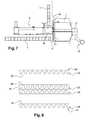
- the insulating cupola mentioned in the description above, is replaced by an element of multilayer insulation cover (MLI) high temperature absorbent, as for example illustrated by the figure 8 .
- MMI multilayer insulation cover
- such an absorbent multilayer insulation cover 21 typically comprises from the outside towards the inside (from top to bottom on the figure 8 ) a titanium sheet 22 of about fifteen microns thick, about four aluminum sheets 23 of about twelve microns thick, about ten sheets of Kapton (registered trademark) 24 with an approximate thickness of 7.5 microns, aluminized on one side, and a twenty five micron aluminized Kapton® sheet, aluminized on one side, these different sheets being separated by about fifteen thin layers of glass cloth called Tissuglas (trade mark) having a thickness a few tens of microns.
- Tissuglas trade mark
- This high-temperature absorbent multilayer insulation cover 21 locally replaces the multilayer insulation cover 9 over a width of approximately 600 mm, in the vicinity of the radiant collector. It is of globally flat shape.
- the titanium foil is positioned on the outer side, that is to say in view of the radiator of the radiant collector 6.
- the cover 21 is fixed on the body of the satellite by a set of pins (not shown figure 7 ), for example made of titanium, and of a type known per se.
- the temperature of the titanium outer sheet heats up and equilibrates as a function of the absorbed solar flux and the radiative coupling with the space and the external environment of the satellite.
- This titanium sheet thus provides the function of solar absorber (thanks to its high solar absorptivity) and a radiative decoupling with the radiator of the collector tube radiator (because of its low IR emissivity).
- the heat absorbed by the outer sheet of the MLI multilayer insulation blanket is partially transmitted to the wall of the machine through the different layers constituting the MLI multilayer insulation blanket by conductive and radiative exchanges between the layers: this heat transmitted is then redistributed in a uniform manner by radiation or by conduction towards the internal parts of the machine not critical in temperature or to an external radiator remote via heat pipes or fluid loops.
- the solution with a "bare" titanium sheet serves as a solar absorber with low thermal performance but which may be sufficient as needed, ie to obtain a cooling of the radiator of the radiator collector tube of the order of 2 ° C to a few degrees Celsius depending on the age of the satellite and its external configuration.
- the first two solutions make it possible to achieve cooling of the radiator of the collector tube radiating up to about ten degrees Celsius.
- This variant does not create a concealment of the field of view of the radiator of the collector tube radiating because of the generally flat shape of the multilayer insulation high temperature absorbing insulation 21.
- the size of the high-absorbency multilayer insulation layer cover element 21 is adaptable according to the number of radiating collector tubes to be equipped, and the thermal specifications,
- this variant constitutes a means of local adjustment of the temperature one or more tubes with a radiant collector in progress or at the end of the development of a satellite program.
- the device is more generally adaptable to any equipment having a part external to the satellite, therefore subject to solar radiation and to be cooled or maintained at a predetermined temperature, for example antenna, optical sensor ...
- the device as described is usable for nozzles to the extent that, when they are not in operation, their temperature must remain below a maximum value, in particular to prevent evaporation of the fuel present in their engines. supply manifold.
- an insulating dome protection as described above, disposed substantially at the neck of the nozzle avoids the heating of said nozzle by the radiation reflected by the satellite wall, and thus contributes to cool it.
- the goal is to increase the view factor towards space, that is to say the solid angle under which the equipment can emit radiation without receiving reflected radiation.
- the insulating dome when it is in operation, also serves as an insulator for the satellite wall with respect to the heat emitted by said nozzle.
Abstract
Description
L'invention relève du domaine du contrôle thermique. Elle concerne plus particulièrement le contrôle thermique actif d'un équipement en environnement spatial, et vise notamment une application dans le cas d'un satellite de télécommunications stabilisé sur trois axes, et doté de tubes à ondes progressives à collecteur rayonnant.The invention relates to the field of thermal control. It relates more particularly to the active thermal control of a device in a space environment, and aims in particular at an application in the case of a telecommunications satellite stabilized on three axes, and equipped with traveling wave tubes with radiant collector.
Il est connu que l'un des problèmes des charges utiles de type électronique embarquées sur des satellites en environnement spatial est la dissipation de la chaleur produite par ladite charge utile.It is known that one of the problems of electronic payloads embedded on satellites in a space environment is the dissipation of the heat produced by said payload.
En effet, dans le cas, par exemple, d'un satellite de télécommunications, la charge utile comporte fréquemment des tubes à ondes progressives ("TOP" ou "TWT" pour Traveling-Wave Tube, en langue anglaise), destinés à une amplification du signal à transmettre avec un très faible bruit de fond. Or ces tubes à ondes progressives dégagent une grande quantité de chaleur, qui doit être dissipée vers l'espace, pour éviter une élévation de température de la charge utile mettant en danger son fonctionnement correct. Le collecteur de ces tubes à ondes progressives à collecteur rayonnant fonctionne fréquemment à une température d'environ 200°C, alors que le tube lui-même est porté à quelques dizaines de degrés C. A titre purement informatif, la chaleur dégagée sur un satellite de télécommunications actuel atteint plusieurs kilowatts, et il est clair que la capacité de dissipation thermique est alors un élément dimensionnant de la puissance de la charge utile.Indeed, in the case, for example, of a telecommunications satellite, the payload often includes traveling wave tubes ("TOP" or "TWT" for Traveling-Wave Tube, in English), intended for amplification of the signal to be transmitted with a very low background noise. Now these traveling wave tubes release a large amount of heat, which must be dissipated to space, to avoid a rise in temperature of the payload endangering its proper operation. The collector of these traveling-wave tubes with radiating collector operates frequently at a temperature of about 200 ° C., whereas the tube itself is brought to a few tens of degrees C. For purely informational purposes, the heat released on a satellite The current telecommunications reach several kilowatts, and it is clear that the heat dissipation capacity is then a sizing element of the power of the payload.
On considère ici le cas de satellites de télécommunications stabilisés en attitude sur trois axes, c'est-à-dire pointant une direction fixe au cours du temps. C'est typiquement le cas de satellites géostationnaires. Il est alors classique de définir pour ces satellites des faces dites Terre et anti-Terre, orientées vers la Terre ou à l'opposé de celle-ci, et des faces Est et Ouest, perpendiculaires à cette direction de la Terre, et des faces Nord et Sud, perpendiculaire à l'axe des pôles terrestres, et donc peu éclairées par le soleil par comparaison aux autres faces du satellite.We consider here the case of telecommunications satellites stabilized in attitude on three axes, that is to say pointing a fixed direction over time. This is typically the case of geostationary satellites. It is then conventional to define for these satellites so-called Earth and anti-Earth faces, oriented towards the Earth or opposite to it, and East and West faces, perpendicular to this direction of the Earth, and faces North and South, perpendicular to the axis of the terrestrial poles, and therefore poorly lit by the sun compared to the other faces of the satellite.
On définit pour la suite de la description le cas "chaud" comme la situation dans laquelle un tube rayonnant est soumis au rayonnement solaire, alors même que le tube rayonnant est en opération et donc produit une chaleur significative à dissiper. Au contraire, on définit le cas "froid" comme le cas où le collecteur rayonnant est dans l'ombre du satellite. On comprend que la différence de température entre ces deux cas se chiffre en dizaines de degrés.For the remainder of the description, the "hot" case is defined as the situation in which a radiating tube is subjected to solar radiation, even though the radiating tube is in operation and therefore produces a significant heat to dissipate. On the contrary, the "cold" case is defined as the case where the radiant collector is in the shadow of the satellite. We understand that the temperature difference between these two cases is in tens of degrees.
Comme on le sait, la dissipation de chaleur ne peut, dans l'environnement spatial, être obtenue que par rayonnement. Divers dispositifs de dissipation de chaleur vers l'espace ont alors été envisagés pour les charges utiles de ces satellites stabilisés.As we know, heat dissipation can only be obtained in the space environment by radiation. Various devices for dissipating heat to space were then envisaged for the payloads of these stabilized satellites.
Parmi ceux-ci, le document brevet
De même, le document brevet
Ce principe du tube à collecteur rayonnant (TCR), connu en soi, est illustré de façon schématique sur la
Le satellite comporte un ensemble de tubes à onde progressive 5, de type connu en soi. Chaque tube à ondes progressives 5 comporte une entrée 10 de signal à amplifier, une sortie 11 de signal amplifié, ainsi qu'un collecteur 6, qui traverse une paroi 3 du satellite et supporte un radiateur à ailettes 7, disposé à l'extérieur du satellite. Les ailettes, typiquement au nombre de huit, sont généralement de longueur égale et s'inscrivent dans un cercle.The satellite comprises a set of
Le rôle du radiateur à ailettes 7 est de rayonner environ 60% de la chaleur produite par le Tube à Ondes Progressives vers l'espace servant de source froide. Le reste de la chaleur, soit environ 40%, est dissipé dans la paroi soutenant le tube (voir
En sens inverse, le radiateur à ailettes 7 reçoit un rayonnement émis par le soleil ou une autre source de rayonnement externe, et le transmet par conduction au collecteur 6 du tube à ondes progressives 5.In the opposite direction, the
Une protection isolante multicouche 9 enveloppe et isole le satellite, réduisant l'entrée de rayonnement solaire ou de rayonnement généré par le radiateur à ailettes dans le satellite.An
Un tel dispositif est nommé tube à collecteur rayonnant (en langue anglaise RCTWT de Radiatively Cooled Traveling-Wave Tube). De tels dispositifs sont classiquement installés sur les arêtes proches des faces Nord et Sud, de manière à ce que les collecteurs rayonnants disposent d'un facteur de vue vers l'espace le plus grand possible (l'angle solide sous lequel l'équipement peut émettre du rayonnement sans recevoir de rayonnement réfléchi), dans une zone peu éclairée par le soleil. Cependant, on comprend que, lorsque une série de ces tubes à collecteur rayonnant 5 sont disposés côte à côte, les radiateurs à ailettes 7 des tubes 5 situés entre d'autres tubes voient leur zone de rayonnement vers l'espace masqué par les radiateurs à ailettes 7 qui les entourent, ce qui réduit leur efficacité.Such a device is called Radiative Cooled Traveling-Wave Tube (RCTWT). Such devices are conventionally installed on the edges near the north and south faces, so that the radiant collectors have a view factor to the largest possible space (the solid angle under which the equipment can emit radiation without receiving reflected radiation) in an area with low sunlight. However, it will be understood that when a series of these radially
De même, du fait de la puissance rayonnée, l'espacement entre les refroidisseurs à ailettes doit éventuellement être augmenté, ce qui implique d'augmenter le pas entre les tubes à ondes progressives au sein de la charge utile. Or il est souhaitable, pour des raisons de performances de la charge utile, de réduire autant que faire se peut la longueur des guides d'ondes entre les antennes réceptrices, et les tubes à ondes progressives 5. Il est donc parfois nécessaire de disposer des tubes au milieu d'une face, ce qui est réduit naturellement la capacité de refroidissement du collecteur rayonnant, particulièrement s'il s'agit d'une face autre que Nord ou Sud.Likewise, because of the radiated power, the spacing between the fin coolers may have to be increased, which implies increasing the pitch between the traveling wave tubes within the payload. However, it is desirable, for reasons of performance of the payload, to reduce as far as possible the length of the waveguides between the receiving antennas, and the
Que ce soit pour des raisons de proximité des tubes ou de tubes dont les collecteurs sont disposés sur une face exposée au rayonnement solaire, certains des collecteurs rayonnant voient, dans les conditions les pires, leur température atteindre 220°C. Une telle température est susceptible de provoquer des dommages au niveau des matériaux composant le collecteur, et par exemple au niveau de la tête 12 du collecteur ("potting" en langue anglaise), qui solidarise les ailettes au collecteur par l'intermédiaire d'une colle. A température trop élevée, le tube associé risque la destruction. Ce problème de réduction de la température maximale des collecteurs rayonnants est donc critique.Whether for reasons of proximity tubes or tubes whose collectors are arranged on a side exposed to solar radiation, some of the radiant collectors see, under the worst conditions, their temperature reach 220 ° C. Such a temperature is likely to cause damage to the materials component of the collector, and for example at the
On comprend que, pour cette application de dissipation de chaleur en ambiance spatiale, les dispositifs cités sont insuffisamment efficaces, ce qui entraîne des limitations dans la puissance dissipable. Les solutions évoquées entrainent des contraintes d'accommodation fortes, des impacts sur les performances RF et sur la masse de la charge utile envisageable. Une augmentation des longueurs des guides d'onde est en effet nécessaire si tous les tubes doivent être implantés sur les arêtes Est/Ouest du Module de Communication Télécom. La température des radiateurs des tubes à collecteur rayonnant est critique en cas chaud, et il n'y a pas de paramètre d'ajustement autre que le pas entre les tubes, qui est figé en début de programme.It is understood that for this application of heat dissipation in a space environment, the devices mentioned are insufficiently effective, which leads to limitations in the dissipable power. The evoked solutions result in strong accommodation constraints, impacts on the RF performances and on the mass of the payload that can be envisaged. An increase in the lengths of the waveguides is indeed necessary if all the tubes must be implanted on the East / West edges of the Telecom Communication Module. The temperature of the radiators of the tubes with radiant collector is critical in the hot case, and there is no adjustment parameter other than the pitch between the tubes, which is fixed at the beginning of the program.
La présente invention a donc pour objet de remédier aux inconvénients précités en proposant un nouveau dispositif de contrôle thermique de charge utile de satellite.The present invention therefore aims to overcome the aforementioned drawbacks by proposing a new satellite payload thermal control device.
Selon un second objectif de l'invention, celle-ci est peu onéreuse à mettre en oeuvre.According to a second objective of the invention, it is inexpensive to implement.
L'invention vise en premier lieu un dispositif de contrôle thermique pour un équipement, ledit équipement étant intégré sur un engin disposé dans un environnement de vide poussé, une partie externe de l'équipement faisant saillie à l'extérieur d'une paroi de l'engin, et étant soumis à un flux de rayonnement par une source externe,
- le dispositif comportant :
- des premiers moyens de captation, d'au moins une partie du rayonnement émis par la source de rayonnement externe, lesdits moyens de captation comportant un écran absorbant adapté à être disposé entre la partie externe de l'équipement et la paroi de l'engin, cet écran présentant, sur au moins une partie de sa face antérieure, destinée à être disposée du côté éloigné de la paroi de l'engin, une surface absorbante avec une absorptivité αSOLAR la plus grande possible dans le domaine du rayonnement solaire, couplée à une faible émissivité εIR dans le spectre infrarouge,
- au moins une seconde surface d'émission avec une forte émissivité εIR dans le spectre infrarouge, rayonnant vers l'extérieur de l'engin mais non vers la partie externe de l'équipement,
- des moyens de transport de chaleur entre la surface absorbante et les surfaces d'émission.
- the device comprising:
- first means for capturing at least a portion of the radiation emitted by the external radiation source, said capturing means comprising an absorbing screen adapted to be disposed between the outer portion of the equipment and the wall of the machine, this screen having, on at least a portion of its front face, intended to be disposed on the side remote from the vehicle wall, an absorbing surface with an absorbency α SOLAR the most large possible in the field of solar radiation, coupled with a low emissivity ε IR in the infrared spectrum,
- at least a second emission surface with a high emissivity ε IR in the infrared spectrum, radiating outwardly from the vehicle but not towards the external part of the equipment,
- heat transport means between the absorbent surface and the emission surfaces.
A titre de simplification, dans un cas particulier de mise en oeuvre, un capteur disposé autour d'un équipement embarqué sur un satellite reçoit le rayonnement solaire dans la bande visible et un radiateur distant évacue cette énergie sous forme de rayonnement infrarouge, de manière à éviter que le rayonnement solaire reçu par le capteur ne soit réfléchi vers l'équipement. On contribue de cette manière à réduire la température de l'équipement.As a simplification, in a particular case of implementation, a sensor disposed around an equipment on board a satellite receives solar radiation in the visible band and a remote radiator discharges this energy in the form of infrared radiation, so as to prevent the solar radiation received by the sensor from being reflected back to the equipment. In this way, the temperature of the equipment is reduced.
Dans cette configuration, il est loisible de disposer les moyens d'émission de rayonnement à distance de l'écran absorbant, et donc typiquement dans une zone non soumise au rayonnement externe, ou ne supportant pas d'équipement sensible à ce dit rayonnement.In this configuration, it is possible to have the radiation emitting means at a distance from the absorbing screen, and therefore typically in an area not subject to external radiation, or not supporting equipment sensitive to said radiation.
On comprend que la seconde surface d'émission rayonne vers l'extérieur de l'engin soit directement, soit indirectement après réflexion sur un revêtement (par exemple de type revêtement isolant multicouche "MLI") de la paroi externe de l'engin.It will be understood that the second emission surface radiates towards the outside of the machine either directly or indirectly after reflection on a coating (for example of the "MLI" multilayer insulating coating) of the outer wall of the vehicle.
Selon un mode de réalisation préféré, l'écran absorbant est réalisé dans un matériau très conducteur de la chaleur, et présente sur au moins une partie de sa face postérieure, adaptée à être orientée vers la paroi de l'engin, une forte émissivité dans le spectre infrarouge, typiquement supérieure ou égale à 0.7.According to a preferred embodiment, the absorbing screen is made of a very heat-conducting material, and has, on at least a portion of its posterior face, adapted to be oriented towards the wall of the machine, a high emissivity in the infrared spectrum, typically greater than or equal to 0.7.
On comprend que dans ce cas, une partie de la chaleur reçue par l'écran absorbant est réémise par sa face arrière.It is understood that in this case, a portion of the heat received by the absorbing screen is reemitted by its rear face.
Plus particulièrement dans ce cas :
- les moyens de transport de chaleur comprennent une boucle fluide haute température à laquelle est liée conductivement l'écran absorbant au niveau d'au moins un évaporateur,
- ladite boucle fluide étant elle-même liée conductivement à un radiateur haute température formant moyens d'émission de rayonnement..
- the heat transport means comprise a high temperature fluid loop to which the absorbing screen is conductively bonded at at least one evaporator,
- said fluid loop being itself conductively bonded to a high temperature radiator forming radiation emission means.
Selon un premier mode de réalisation, l'écran absorbant présente une forme globalement concave apte à être disposée autour de la partie externe de l'équipement.According to a first embodiment, the absorbent screen has a generally concave shape adapted to be arranged around the outer part of the equipment.
Dans ce cas, selon une mise en oeuvre avantageuse, l'écran absorbant comporte une première surface sensiblement plane et apte à être disposée de façon parallèle à la paroi du satellite, dotée de deux rebords latéraux inclinés selon un angle d'environ 20 à 50° par rapport à ladite première surface.In this case, according to an advantageous embodiment, the absorbent screen comprises a first substantially flat surface and adapted to be arranged parallel to the satellite wall, provided with two lateral flanges inclined at an angle of about 20 to 50 ° with respect to said first surface.
Alternativement, l'écran absorbant comporte une surface plane, la partie centrale de ladite surface plane recevant un revêtement absorbant présentant une forte absorptivité du rayonnement solaire, les bords de cette surface recevant un revêtement hautement émissif dans le domaine infrarougeAlternatively, the absorbent screen comprises a flat surface, the central portion of said flat surface receiving an absorbent coating having a high absorption of solar radiation, the edges of this surface receiving a highly emissive coating in the infrared range
Selon un mode préféré de réalisation, l'écran absorbant comporte des moyens de fixation et d'isolation conductive de manière à le disposer de façon sensiblement perpendiculaire à l'axe principal de la partie externe de l'équipement.According to a preferred embodiment, the absorbent screen comprises fixing means and conductive insulation so as to dispose substantially perpendicular to the main axis of the outer portion of the equipment.
Dans un mode de réalisation facilitant le montage du dispositif tardivement sur un satellite en cours d'intégration, l'écran absorbant est composée de plusieurs parties adaptées à être assemblées autour de la partie externe de l'équipement, lorsque celui-ci est déjà installé sur un engin.In one embodiment facilitating the mounting of the device late on a satellite being integrated, the absorbent screen is composed of several parts adapted to be assembled around the outer part of the equipment, when it is already installed. on a craft.
Dans une variante avantageuse, l'écran absorbant est un élément de couverture isolante multicouche haute température absorbante comportant une feuille de forte absorptivité du rayonnement solaire et faible émissivité εIR dans le spectre infrarouge. Cette disposition correspond à une mise en oeuvre peu onéreuse du dispositifIn an advantageous variant, the absorbent screen is a multilayer insulating high temperature absorbent insulating element comprising a sheet of high solar radiation absorptivity and low emissivity ε IR in the infrared spectrum. This arrangement corresponds to an inexpensive implementation of the device
Sous un autre aspect, l'invention vise un satellite, comportant au moins un dispositif de contrôle thermique tel qu'exposé plus haut.In another aspect, the invention relates to a satellite, comprising at least one thermal control device as described above.
Sous encore un autre aspect, l'invention vise un procédé d'aménagement thermique d'un satellite tel qu'exposé, comportant une étape d'installation d'au moins un écran absorbant sur la partie externe d'au moins un équipement, selon leur température maximale estimée ou mesurée lors d'un essai.In yet another aspect, the invention relates to a method of thermal management of a satellite as described, comprising a step of installing at least one absorbing screen on the outer part of at least one equipment, according to their maximum temperature estimated or measured during a test.
Sous encore un autre aspect, l'invention vise un procédé d'aménagement thermique d'un satellite tel qu'exposé, comportant une étape d'installation d'au moins un écran absorbant sur au moins un radiateur de tubes à collecteur rayonnant, selon leur température maximale estimée.In yet another aspect, the invention relates to a method of thermal management of a satellite as described, comprising a step of installing at least one absorbing screen on at least one radiant collector tube radiator, according to their estimated maximum temperature.
Dans ce cas, préférentiellement, le procédé comporte une étape d'installation d'au moins un écran absorbant sur au moins un radiateur de tube disposé au centre de faces Est ou Ouest, ou sur au moins radiateur disposé entre d'autres radiateurs.In this case, preferably, the method comprises a step of installing at least one absorbent screen on at least one tube radiator disposed at the center of East or West faces, or at least one radiator disposed between other radiators.
Les buts et avantages de l'invention seront mieux compris à la lecture de la description et des dessins d'un mode particulier de réalisation, donné à titre d'exemple non limitatif, et pour lequel les dessins représentent :
- -
figure 1 (déjà citée) : un schéma de principe d'un tube à collecteur rayonnant, en vue de côté, - -
figure 2 (déjà citée) : un schéma de principe des modes de dissipation de la chaleur générée par un tube à collecteur rayonnant, - -
figure 3 : un schéma explicatif de l'influence du rayonnement solaire sur la température du radiateur d'un tube à collecteur rayonnant, en l'absence de dispositif tel que décrit à titre d'exemple de mise en oeuvre de l'invention, - -
figure 4 : un schéma analogue à lafigure 3 , lorsqu'une coupole absorbante est installée autour du radiateur, - -
figure 5 : une illustration d'une première variante de mis en oeuvre de l'invention, - -
figure 6 : une illustration d'une seconde variante de mise en oeuvre de l'invention, utilisant une boucle fluide et un radiateur déporté, - -
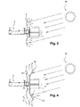
figure 7 : une illustration d'une autre variante de mise en oeuvre de l'invention, utilisant une couverture isolante multicouche spécifique et absorbante, - -
figure 8 : une section schématique d'une couverture d'isolation multicouche haute température, telle qu'utilisée dans la variante de lafigure 7 .
- -
figure 1 (already mentioned): a schematic diagram of a collector tube radiating, in side view, - -
figure 2 (already mentioned): a schematic diagram of the heat dissipation modes generated by a collector tube, - -
figure 3 an explanatory diagram of the influence of solar radiation on the temperature of the radiator of a collector tube radiating, in the absence of device as described by way of example of implementation of the invention, - -
figure 4 : a scheme similar to thefigure 3 , when an absorbent dome is installed around the radiator, - -
figure 5 : an illustration of a first variant of implementation of the invention, - -
figure 6 : an illustration of a second alternative embodiment of the invention, using a fluid loop and a radiator remote, - -
figure 7 an illustration of another variant embodiment of the invention, using a specific and absorbent multilayer insulating blanket, - -
figure 8 : a schematic section of a high temperature multilayer insulation blanket, as used in the variant of thefigure 7 .
L'invention est destinée à être utilisée notamment dans le cadre d'un engin spatial, dans le présent exemple nullement limitatif un satellite en orbite autour de la Terre. On considère ici un satellite de télécommunications en orbite géostationnaire stabilisé sur trois axes. Il reste cependant clair que l'invention s'applique également à tout autre type de support placé dans le vide et destiné à dissiper sa chaleur purement par rayonnement.The invention is intended to be used especially in the context of a spacecraft, in the present example in no way limiting a satellite orbiting the Earth. We consider here a telecommunications satellite in geostationary orbit stabilized on three axes. However, it remains clear that the invention also applies to any other type of support placed in the vacuum and intended to dissipate its heat purely by radiation.
On définit pour la suite de la description le terme de spectre infrarouge par la bande de longueurs d'ondes comprise approximativement entre 780 nm et 100 µm, et le spectre solaire par la bande comprise entre 10 et 780 nm.For the remainder of the description, the term infrared spectrum is defined by the wavelength band lying approximately between 780 nm and 100 μm, and the solar spectrum by the band between 10 and 780 nm.
L'invention est ici décrite dans une application à un tube à collecteur rayonnant (tube radiatif), tel que décrit plus haut en référence aux
Tel qu'illustré
Dans la mise en oeuvre nullement limitative illustrée
La première surface 14 comporte un évidement (non visible sur la
La largeur /1 de la première surface 14 est supérieure à l'envergure des ailettes du radiateur 7, et ici d'environ quarante centimètres, pour une longueur qui dépend du nombre de collecteurs rayonnants concernés par le dispositif. A titre purement indicatif, la longueur de la première surface peut ainsi être de l'ordre de 120 centimètres si l'écran absorbant 13 doit être disposé derrière cinq collecteurs rayonnants.The width / 1 of the
La largeur /2 des rebords latéraux est ici de l'ordre de dix centimètres, avec une longueur égale à celle de la première surface 14 de l'écran absorbant 13.The width / 2 of the lateral flanges is here of the order of ten centimeters, with a length equal to that of the
Dans une variante (non illustrée) pour laquelle l'écran absorbant 13 entoure un seul collecteur rayonnant 7, l'écran comporte une première surface 14 en forme de disque, entouré par un bord incliné 16 tronconique.In a variant (not shown) for which the absorbing
L'écran absorbant 13 est réalisé en matériau léger très conducteur de la chaleur, adapté à supporter une température de plus de 200°C. Il est dans le présent exemple réalisé en aluminium, selon une technique connue de l'homme de l'art. Dans une variante de réalisation, l'écran absorbant 13 est réalisé en matériau composite à haute conductivité.The
De manière à faciliter son installation autour d'un ou plusieurs radiateurs à ailettes 7 de collecteurs rayonnants, l'écran absorbant 13 est ici réalisé en deux parties sensiblement symétriques, assemblées en place, par exemple par vissage ou autre technique connue.In order to facilitate its installation around one or more radiators to
La face avant de l'écran absorbant 13 (côté radiateur à ailettes 7) reçoit, dans le présent exemple, un revêtement absorptif en nickel poli, de manière à lui conférer une forte absorptivité du rayonnement solaire, typiquement αSOLAR =0,9, couplée à une faible émissivité dans l'infrarouge εIR =0,06.The front face of the absorbent screen 13 (finned radiator side 7) receives, in the present example, a polished nickel absorptive coating, so as to give it a high absorptivity of solar radiation, typically α SOLAR = 0.9, coupled with low emissivity in the infrared ε IR = 0.06.
La face arrière de l'écran absorbant 13 (côté couverture isolante multicouches "MLI") reçoit, dans le présent exemple, un revêtement hautement émissif, par exemple de type connu sous le nom commercial Kepla coat (marque déposée) qui est un revêtement noir à oxydation plasmique.The back side of the absorbent screen 13 (multilayer insulating blanket side "MLI") receives, in the present example, a highly emissive coating, for example of the type known under the trade name Kepla coat (trademark) which is a black coating with plasma oxidation.
Ce revêtement hautement émissif est ici caractérisé par les valeurs suivantes
- émissivité solaire αSOLAR = 0.9,
- émissivité εIR dans le domaine infrarouge approximativement égale à 0.8.
- solar emissivity α SOLAR = 0.9,
- IR emissivity in the infrared range approximately equal to 0.8.
Il est clair que dans la présente mise en oeuvre, l'écran absorbant 13 est destiné à être placé en orbite avec le satellite, et doit donc être compatible avec l'environnement spatial. Ses caractéristiques mécaniques et géométriques sont donc adaptées pour tenir compte des contraintes au lancement et lors du vol spatial : tenue au dégazage, cyclage thermique, charges électrostatiques, irradiations UV, flux aérothermique au lancement, contraintes mécaniques au lancement et en vol (particules). L'écran absorbant 13 est solidarisé aux parois 2, 3 du satellite par des moyens connus en soi, en respectant un découplage thermique entre l'écran absorbant 13 et le satellite, et le dispositif comporte une mise à la masse de cet écran absorbant 13.It is clear that in the present implementation, the absorbing
L'écran absorbant 13 est installé autour d'un certain nombre de radiateurs 7 de tubes à collecteur rayonnant 5, selon leur température maximale, par exemple telle que calculée durant la phase de conception, ou observée lors de tests de simulation. En particulier, cet écran absorbant 13 peut être typiquement installé sur les radiateurs 7 de tubes 5 disposés au centre de faces Est ou Ouest, ou sur des radiateurs situés entre d'autres radiateurs, et disposant, de ce fait, d'un angle solide de rayonnement inférieur. Il est clair que la forme et la surface de l'écran absorbant 13 peuvent être adaptées aux conditions spécifiques d'environnement de chaque tube, ce qui fournit une grande souplesse dans l'aménagement.
Le mode de fonctionnement s'apprécie par comparaison avec la
En effet, il a été constaté que pour un radiateur 7 supposé émettre vers l'espace 40 watts de chaleur provenant du collecteur rayonnant 6, plus de 20 watts additionnels étaient reçus en provenance de l'environnement externe : protection multicouche, autres radiateurs, rayonnement solaire direct. C'est-à-dire qu'un tiers de la chaleur rayonnée par le radiateur est due à des flux en provenance de l'environnement externe. Une telle situation peut amener le radiateur à fonctionner 60°C au dessus de sa température théorique de fonctionnement, typiquement à 220°C au lieu de 160°C en l'absence de flux externes.Indeed, it has been found that for a
Par contre, lorsqu'un dispositif de contrôle thermique tel que décrit plus haut est installé autour d'un collecteur rayonnant, la face avant de l'écran absorbant 13, tournée vers le radiateur à ailettes 7, absorbe la plus grande partie du rayonnement solaire incident, qui n'est alors plus réfléchi du fait de la forte absorptivité ni réémis du fait de la faible émissivité de cette face dans l'infrarouge vers le radiateur 7. La chaleur absorbée est transmise par l'écran absorbant, réalisé en matériau fortement conductif, vers sa face arrière. Celle-ci est hautement émissive dans l'infrarouge, et réémet en conséquence la chaleur de l'écran absorbant 13 vers la protection isolante multicouche 9, et vers l'espace. De cette manière, la contribution du rayonnement solaire à l'échauffement du radiateur 7 se trouve nettement réduite, ainsi que la contribution de rayonnement infra rouge venant de la paroi de l'engin.On the other hand, when a thermal control device as described above is installed around a radiant collector, the front face of the
De plus, la face avant de l'écran absorbant, de faible émissivité infrarouge, réfléchit le rayonnement infrarouge émis par le radiateur à ailettes 7, ce qui maximise l'énergie rayonnée vers l'espace.In addition, the front face of the absorbent screen, low emissivity infrared, reflects the infrared radiation emitted by the
En cas dit "chaud", c'est-à-dire lorsque le tube à collecteur rayonnant est en fonctionnement, la réduction de température du radiateur obtenu par utilisation d'un dispositif tel que décrit, a été estimée entre 10°C et 20°C suivant la position du tube au sein du satellite, et la configuration externe autour du tube.In the so-called "hot" case, ie when the radiant collector tube is in operation, the temperature reduction of the radiator obtained by using a device as described, has been estimated between 10 ° C. and 20 ° C. ° C according to the position of the tube within the satellite, and the external configuration around the tube.
Le dispositif selon l'invention permet donc de réduire dans ce cas chaud la température du radiateur 7 des tubes à collecteur rayonnant (partie externe au niveau du collecteur rayonnant 6) qui est un élément critique. Elle permet de maintenir la température du radiateur à ailettes 7 à un niveau acceptable suivant les configurations.The device according to the invention thus makes it possible to reduce in this hot case the temperature of the
Ceci permet une plus grande souplesse au niveau de l'accommodation de ces tubes sur un satellite et une meilleure optimisation de la charge utile. Il en résulte en effet un élargissement des possibilités d'implantation des tubes à collecteur rayonnant sur un satellite de télécommunications, et une possibilité d'optimiser les longueurs de guides d'onde.This allows greater flexibility in the accommodation of these tubes on a satellite and better optimization of the payload. This results in an enlargement of the possibilities of implantation of the tubes with collector radiating on a telecommunications satellite, and a possibility of optimizing the lengths of waveguides.
L'aménagement interne et externe de la charge utile s'en trouve donc facilité, car l'invention peut être appliquée localement sur un ou plusieurs tubes en tant que paramètre d'ajustement supplémentaire.The internal and external arrangement of the payload is therefore facilitated, because the invention can be applied locally to one or more tubes as an additional adjustment parameter.
De façon résumée, les avantages du dispositif de dissipation de chaleur selon l'invention sont :
- une simplicité de réglage de la température d'un tube radiatif (technologie et pièce existantes),
- une capacité à réaliser cet ajustement localement et tardivement en cours de programme si nécessaire,
- une intégrité mécanique du tube à ondes progressives non modifiée,
- une réduction du stress thermique dudit tube,
- un faible coût de mise oeuvre,
- un impact sur la masse mesuré,
- une possibilité de réduire le pas (espacement) entre des tubes, du fait de leur température de fonctionnement plus basse.
- a simplicity of regulating the temperature of a radiative tube (existing technology and part),
- an ability to make this adjustment locally and late in the program if necessary,
- mechanical integrity of the unmodified traveling wave tube,
- a reduction of the heat stress of said tube,
- a low cost of implementation,
- an impact on the measured mass,
- a possibility of reducing the pitch (spacing) between tubes because of their lower operating temperature.
La portée de la présente invention ne se limite pas aux détails des formes de réalisation ci-dessus considérées à titre d'exemple, mais s'étend au contraire aux modifications à la portée de l'homme de l'art.The scope of the present invention is not limited to the details of the above embodiments considered by way of example, but instead extends to modifications within the scope of those skilled in the art.
L'application est possible sur tous les types de tubes à collecteur rayonnant comportant des moyens de fixer un écran de découplage radiatif, en s'adaptant à leur géométrie ou dimensions spécifiques.The application is possible on all types of tubes with radiant collector comprising means for fixing a radiative decoupling screen, by adapting to their specific geometry or dimensions.
Dans une variante de mise en oeuvre, le revêtement hautement émissif de la face arrière de l'écran absorbant 13 est un revêtement de type «céramique blanche avec oxydation plasmique». Ce revêtement est destiné aux hautes températures jusqu'à +450°C, ce qui est largement compatible de la température maximale du radiateur. L'épaisseur du revêtement est de l'ordre de 100µm,In an alternative embodiment, the highly emissive coating of the rear face of the
Ses caractéristiques thermo-optiques sont : une absorptivité solaire début de vie voisine de 0.26 / absorptivité solaire fin de vie inférieure à environ 0.55, et une émissivité ε en infrarouge proche de 0.83.Its thermo-optical characteristics are: an early solar energy absorptivity close to 0.26 / solar end-of-life absorptivity less than approximately 0.55, and an emissivity ε in the near infrared of 0.83.
Dans une autre variante, la face arrière de l'écran absorbant 13 (côté éloigné de la paroi de l'engin) reçoit un revêtement hautement émissif de type anodisation sulfurique.In another variant, the rear face of the absorbent screen 13 (remote side of the vehicle wall) receives a highly emissive coating type sulfuric anodizing.
Ce revêtement est caractérisé par les valeurs suivantes :
- absorptivité solaire début de vie αSOLAR = 0.45 / absorptivité solaire fin de vie αSOLAR = 0.7,
- émissivité εIR dans le domaine infrarouge approximativement égale à 0.8.
- solar absorptivity early life α SOLAR = 0.45 / solar absorptivity end of life α SOLAR = 0.7,
- IR emissivity in the infrared range approximately equal to 0.8.
Dans une variante de forme d'écran absorbant 13 illustrée par la
Cette disposition permet de transférer à distance la chaleur reçue du soleil juste autour du collecteur rayonnant, avant de la réémettre vers l'espace.This arrangement remotely transfers the heat received from the sun just around the radiant collector, before re-emitting it to space.
Cette variante de mise en oeuvre présente l'avantage de réduire l'encombrement du dispositif.This variant of implementation has the advantage of reducing the size of the device.
Dans une autre variante de mise en oeuvre, illustrée par la
Le joint hautement conducteur, conformé par exemple en feuille ou plaque mince rectangulaire, est de type composé de graphite pratiquement pur, et typiquement disponible sous le nom commercial de joint Sigraflex (marque déposée).The highly conductive seal, shaped for example as a rectangular sheet or thin plate, is of the substantially pure graphite compound type, and is typically available under the trade name of Sigraflex (registered trade mark).
La pièce d'interface est plaquée mécaniquement contre le joint conducteur en une série de points de fixation, de manière à assurer la meilleure conduction possible entre l'écran absorbant 13 et la pièce d'interface. Cette pièce d'interface est ici réalisée en matériau métallique, par exemple aluminium.The interface piece is mechanically plated against the conductive seal in a series of attachment points, so as to ensure the best possible conduction between the
Elle supporte l'évaporateur, disposé sensiblement le long de son axe longitudinal. Cet évaporateur est de type connu en soi.It supports the evaporator, arranged substantially along its longitudinal axis. This evaporator is of a type known per se.
Chaque boucle fluide LHP (préférentiellement au nombre de deux à titre de redondance) est également couplée conductivement à un radiateur haute température 20 déporté à distance ou sur une autre face du satellite, par des moyens connus en soi.Each fluid loop LHP (preferably two in number as a redundancy) is also conductively coupled to a high temperature radiator remotely remote or on another face of the satellite, by means known per se.
On entend par déporté dans le satellite le fait que le radiateur haute température 20 peut être disposé à plusieurs dizaines de centimètres de l'évaporateur si besoin est, selon les contraintes d'aménagement des faces du satellite, et en installant cependant préférentiellement le radiateur haute température 20 sur une face non soumise au rayonnement solaire.The term "satellite" is meant to mean that the high-
Dans cette variante, l'écran absorbant 13 comporte, comme dans la description donnée plus haut, un revêtement absorbant adapté à absorber le rayonnement solaire sur sa face avant. Par contre, il ne comporte pas de revêtement particulier sur sa face arrière, la zone fortement émissive étant déportée au niveau du radiateur haute température 20.In this variant, the
Sur le radiateur à haute température 20, le tube de la boucle fluide est avantageusement disposé en forme de serpentin pour homogénéiser la température dudit radiateur.On the
Le radiateur à haute température présente par exemple une émissivité dans le domaine infrarouge supérieure à 0.82, une absorptivité solaire en début de vie inférieure à 0.2, et une absorptivité solaire en fin de vie inférieure à 0.27. Il peut par exemple comporter un revêtement de type Kepla coat (marque déposée), déjà mentionné, ou tout autre revêtement fortement émissif dans le domaine infrarouge.The high temperature radiator for example has an emissivity in the infrared range greater than 0.82, a solar absorptivity at the beginning of life less than 0.2, and a solar absorptivity at the end of life less than 0.27. It may for example comprise a coating of Kepla coat type (registered trademark), already mentioned, or any other highly emissive coating in the infrared range.
L'ensemble formé par la coupole absorbante 13, la boucle fluide et le radiateur haute température est dimensionné selon des règles classiques bien connues de l'homme du métier.The assembly formed by the
Une thermistance, non illustrée sur les figures, est installée sur le radiateur à ailettes 7 de manière à contrôler sa température au cours du temps.A thermistor, not shown in the figures, is installed on the
Le dispositif comporte également une connectique (non illustrée sur les figures) adaptée à l'activation de la boucle fluide haute température, ainsi que des moyens de commande associés (également non illustrés).The device also comprises a connector (not shown in the figures) adapted to the activation of the high temperature fluid loop, as well as associated control means (also not shown).
Ces moyens de commande prennent typiquement la forme d'un processeur doté d'une mémoire supportant un logiciel de pilotage de la boucle fluide, selon des données d'environnement reçues par des capteurs d'environnement, notamment : flux solaire reçu, température du radiateur à ailettes 7.These control means typically take the form of a processor with a memory supporting a software for controlling the fluid loop, according to environmental data received by environmental sensors, in particular: solar flux received, temperature of the radiator with
Dans encore une autre variante de mise en oeuvre (voir
Comme on le voit, une telle couverture d'isolation multicouche absorbante 21, connue en soi, comporte typiquement de l'extérieur vers l'intérieur (soit de haut en bas sur la
Cette couverture d'isolation multicouche haute température absorbante 21 remplace localement la couverture d'isolation multicouche 9 sur une largeur de 600mm environ, au voisinage du collecteur rayonnant. Elle est de forme globalement plane. La feuille de titane est positionnée coté externe, c'est à dire en vue du radiateur du collecteur rayonnant 6.This high-temperature absorbent
Dans le présent exemple de mise en oeuvre, la couverture 21 est fixée sur le corps du satellite par un ensemble de pions (non illustrés
On comprend qu'en fonctionnement, la température de la feuille externe en titane s'échauffe et s'équilibre en fonction du flux solaire absorbé et des couplages radiatifs avec l'espace et l'environnement externe du satellite. Cette feuille en titane assure donc la fonction d'absorbeur solaire (grâce à sa forte absorptivité solaire) et un découplage radiatif avec le radiateur du tube à collecteur rayonnant (du fait de sa faible émissivité IR). La chaleur absorbée par la feuille externe de la couverture d'isolation multicouche MLI est partiellement transmise vers la paroi de l'engin à travers les différentes couches constituant la couverture d'isolation multicouche MLI par échanges conductifs et radiatifs entre les couches : cette chaleur transmise est redistribuée alors de manière uniforme par rayonnement ou par conduction vers les parties internes de l'engin non critiques en température ou vers un radiateur externe déporté via des caloducs ou des boucles fluides.It is understood that in operation, the temperature of the titanium outer sheet heats up and equilibrates as a function of the absorbed solar flux and the radiative coupling with the space and the external environment of the satellite. This titanium sheet thus provides the function of solar absorber (thanks to its high solar absorptivity) and a radiative decoupling with the radiator of the collector tube radiator (because of its low IR emissivity). The heat absorbed by the outer sheet of the MLI multilayer insulation blanket is partially transmitted to the wall of the machine through the different layers constituting the MLI multilayer insulation blanket by conductive and radiative exchanges between the layers: this heat transmitted is then redistributed in a uniform manner by radiation or by conduction towards the internal parts of the machine not critical in temperature or to an external radiator remote via heat pipes or fluid loops.
La solution avec une feuille de titane "nue" fait office d'absorbeur solaire avec des performances thermiques faibles mais qui peuvent suffire suivant le besoin, c'est à dire permettre d'obtenir un refroidissement du radiateur du tube à collecteur rayonnant de l'ordre de 2°C à quelques degrés Celsius suivant l'âge du satellite et sa configuration externe.The solution with a "bare" titanium sheet serves as a solar absorber with low thermal performance but which may be sufficient as needed, ie to obtain a cooling of the radiator of the radiator collector tube of the order of 2 ° C to a few degrees Celsius depending on the age of the satellite and its external configuration.
Suivant le cahier des charges thermique, il est loisible d'améliorer le concept exposé ci-dessus en déposant sur cette feuille de Titane un revêtement absorbant plus performant du type :
- - Ni brillant / Ni noir : absorptivité solaire début de vie et fin de vie α = 0.9 et émissivité ε = 0.06
- - NiCr / SiO : absorptivité solaire début de vie et fin de vie α = 0.7 et émissivité ε = 0.045
- - Cr brillant / Cr noir : absorptivité solaire début de vie et fin de vie α = 0.95 et émissivité ε = 0.15
- - Neither glossy / Ni black: solar absorptivity early life and end of life α = 0.9 and emissivity ε = 0.06
- - NiCr / SiO: solar absorptivity early life and end of life α = 0.7 and emissivity ε = 0.045
- - Cr brilliant / Cr black: solar absorptivity early life and end of life α = 0.95 and emissivity ε = 0.15
Les deux premières solutions permettent d'atteindre un refroidissement du radiateur du tube à collecteur rayonnant pouvant aller jusqu'à une dizaine de degré Celsius environ.The first two solutions make it possible to achieve cooling of the radiator of the collector tube radiating up to about ten degrees Celsius.
Les revêtements ci-dessus peuvent aussi être utilisés dans d'autres exemples de l'invention.The above coatings may also be used in other examples of the invention.
Cette variante permet ici encore de ne pas nécessiter de modification de l'intégrité du tube à collecteur rayonnant. Elle permet par ailleurs d'obtenir une masse additionnelle très faible à embarquer sur le satellite tout en étant de mise en oeuvre particulièrement simple.This variant again makes it possible not to require modification of the integrity of the radiant collector tube. It also makes it possible to obtain a very small additional mass to be loaded on the satellite while being particularly simple to implement.
Cette variante ne créé pas d'occultation du champ de vue du radiateur du tube à collecteur rayonnant, du fait de la forme globalement plane de la couverture d'isolation multicouche haute température absorbante 21.This variant does not create a concealment of the field of view of the radiator of the collector tube radiating because of the generally flat shape of the multilayer insulation high
Elle n'a pas d'impact sur la géométrie externe du satellite.It has no impact on the external geometry of the satellite.
On comprend que la taille de l'élément de couverture d'isolation multicouche haute température absorbante 21 est adaptable suivant le nombre de tubes à collecteur rayonnants à équiper, et le cahier des charges thermique,It is understood that the size of the high-absorbency multilayer insulation
Enfin, cette variante constitue un moyen d'ajustement local de la température d'un ou plusieurs tubes à collecteur rayonnant en cours ou en fin de développement d'un programme de satellite.Finally, this variant constitutes a means of local adjustment of the temperature one or more tubes with a radiant collector in progress or at the end of the development of a satellite program.
Dans toute la description, on a utilisé à titre d'exemple le cas de tubes à collecteur rayonnant, dont le collecteur comporte un radiateur externe au satellite, et destiné à dissiper la chaleur émise par le tube.Throughout the description, it has been used by way of example the case of tubes with radiant collector, whose collector comprises a radiator external to the satellite, and intended to dissipate the heat emitted by the tube.
Il reste clair que le dispositif, tel qu'il a été exposé ci-dessus, est plus généralement adaptable à tout équipement comportant une partie externe au satellite, donc soumis au rayonnement solaire et devant être refroidi ou maintenu à une température prédéterminée, par exemple antenne, capteur optique...It remains clear that the device, as described above, is more generally adaptable to any equipment having a part external to the satellite, therefore subject to solar radiation and to be cooled or maintained at a predetermined temperature, for example antenna, optical sensor ...
En particulier, le dispositif tel que décrit est utilisable pour des tuyères dans la mesure où, lorsqu'elles ne sont pas en fonctionnement, leur température doit demeurer en dessous d'une valeur maximale, notamment pour éviter l'évaporation du carburant présent dans leur tubulure d'alimentation. Dans ce cas, une protection en coupole isolante, telle qu'exposée plus haut, disposée sensiblement au niveau du col de la tuyère permet d'éviter le réchauffement de ladite tuyère par le rayonnement réfléchi par la paroi du satellite, et contribue donc à refroidir celle-ci.In particular, the device as described is usable for nozzles to the extent that, when they are not in operation, their temperature must remain below a maximum value, in particular to prevent evaporation of the fuel present in their engines. supply manifold. In this case, an insulating dome protection, as described above, disposed substantially at the neck of the nozzle avoids the heating of said nozzle by the radiation reflected by the satellite wall, and thus contributes to cool it.
On comprend qu'ici encore, le but est d'augmenter le facteur de vue vers l'espace, c'est-à-dire l'angle solide sous lequel l'équipement peut émettre du rayonnement sans recevoir de rayonnement réfléchi.It is understood that here again, the goal is to increase the view factor towards space, that is to say the solid angle under which the equipment can emit radiation without receiving reflected radiation.
Il est à noter que, dans le cas de tuyère, lorsque celle-ci est en fonctionnement, la coupole isolante sert également d'isolant pour la paroi du satellite vis-à-vis de la chaleur émise par ladite tuyère.It should be noted that, in the case of a nozzle, when it is in operation, the insulating dome also serves as an insulator for the satellite wall with respect to the heat emitted by said nozzle.
Claims (11)
caractérisé en ce que le dispositif comporte :
characterized in that the device comprises:
Applications Claiming Priority (1)
| Application Number | Priority Date | Filing Date | Title |
|---|---|---|---|
| FR1003405A FR2963981A1 (en) | 2010-08-20 | 2010-08-20 | ABSORBENT COVER FOR RADIANT COLLECTOR TUBES |
Publications (2)
| Publication Number | Publication Date |
|---|---|
| EP2420448A1 true EP2420448A1 (en) | 2012-02-22 |
| EP2420448B1 EP2420448B1 (en) | 2014-01-01 |
Family
ID=43530590
Family Applications (1)
| Application Number | Title | Priority Date | Filing Date |
|---|---|---|---|
| EP20110177318 Active EP2420448B1 (en) | 2010-08-20 | 2011-08-11 | Absorbing dome for a radiating collector tube |
Country Status (3)
| Country | Link |
|---|---|
| US (1) | US9038960B2 (en) |
| EP (1) | EP2420448B1 (en) |
| FR (1) | FR2963981A1 (en) |
Cited By (2)
| Publication number | Priority date | Publication date | Assignee | Title |
|---|---|---|---|---|
| CN106628243A (en) * | 2016-08-24 | 2017-05-10 | 北京卫星环境工程研究所 | Thermal noise test system heating window based on travelling wave tube |
| CN117429629A (en) * | 2023-12-21 | 2024-01-23 | 中国人民解放军国防科技大学 | Infrared optical type heat protection auxiliary heat radiation device for hypersonic aircraft |
Families Citing this family (3)
| Publication number | Priority date | Publication date | Assignee | Title |
|---|---|---|---|---|
| US9352855B2 (en) * | 2013-04-09 | 2016-05-31 | Lockheed Martin Corporation | Heat generating transfer orbit shield |
| US10583940B2 (en) | 2015-03-03 | 2020-03-10 | York Space Systems LLC | Pressurized payload compartment and mission agnostic space vehicle including the same |
| CN114413060A (en) * | 2021-12-20 | 2022-04-29 | 上海空间推进研究所 | Device for reducing on-rail temperature of control valve of space engine |
Citations (6)
| Publication number | Priority date | Publication date | Assignee | Title |
|---|---|---|---|---|
| US3817320A (en) * | 1971-03-02 | 1974-06-18 | Rca Corp | Passive cooler |
| US4098956A (en) * | 1976-08-11 | 1978-07-04 | The United States Of America As Represented By The Secretary Of The Interior | Spectrally selective solar absorbers |
| EP0376827A1 (en) | 1988-12-30 | 1990-07-04 | Thomson Tubes Electroniques | Electron beam tube partially cooled by direct radiation |
| EP0831513A1 (en) * | 1996-09-19 | 1998-03-25 | Nec Corporation | Emissive heat radiator |
| US5862462A (en) | 1994-06-15 | 1999-01-19 | Space Systems/Loral, Inc. | Power enhancement techniques for high power satellites |
| EP1065450A2 (en) * | 1999-06-30 | 2001-01-03 | Acktar Ltd. | Absorber-reflector for solar heating |
Family Cites Families (4)
| Publication number | Priority date | Publication date | Assignee | Title |
|---|---|---|---|---|
| US6073887A (en) * | 1997-07-16 | 2000-06-13 | Space Systems/Loral, Inc. | High power spacecraft with full utilization of all spacecraft surfaces |
| US6119979A (en) * | 1997-09-15 | 2000-09-19 | Sky Station International, Inc. | Cyclical thermal management system |
| US6394395B1 (en) * | 2000-03-15 | 2002-05-28 | Lockheed Martin Corporation | Combination solar array assembly and antenna for a satellite |
| US6921050B2 (en) * | 2003-01-17 | 2005-07-26 | Northrop Grumman Corporation | Solar torque control using thin film directionally reflective, emissive, absorptive and transmissive surfaces |
-
2010
- 2010-08-20 FR FR1003405A patent/FR2963981A1/en not_active Withdrawn
-
2011
- 2011-08-11 EP EP20110177318 patent/EP2420448B1/en active Active
- 2011-08-22 US US13/214,527 patent/US9038960B2/en active Active
Patent Citations (6)
| Publication number | Priority date | Publication date | Assignee | Title |
|---|---|---|---|---|
| US3817320A (en) * | 1971-03-02 | 1974-06-18 | Rca Corp | Passive cooler |
| US4098956A (en) * | 1976-08-11 | 1978-07-04 | The United States Of America As Represented By The Secretary Of The Interior | Spectrally selective solar absorbers |
| EP0376827A1 (en) | 1988-12-30 | 1990-07-04 | Thomson Tubes Electroniques | Electron beam tube partially cooled by direct radiation |
| US5862462A (en) | 1994-06-15 | 1999-01-19 | Space Systems/Loral, Inc. | Power enhancement techniques for high power satellites |
| EP0831513A1 (en) * | 1996-09-19 | 1998-03-25 | Nec Corporation | Emissive heat radiator |
| EP1065450A2 (en) * | 1999-06-30 | 2001-01-03 | Acktar Ltd. | Absorber-reflector for solar heating |
Non-Patent Citations (1)
| Title |
|---|
| LAMPERT C M: "COATINGS FOR ENHANCED PHOTOTHERMAL ENERGY COLLECTION", SOLAR ENERGY MATERIALS, NORTH-HOLLAND PUBLISHING COMPANY, AMSTERDAM, NL, vol. 1, 1 January 1979 (1979-01-01), pages 319 - 341, XP000900880, ISSN: 0165-1633, DOI: 10.1016/0165-1633(79)90001-7 * |
Cited By (4)
| Publication number | Priority date | Publication date | Assignee | Title |
|---|---|---|---|---|
| CN106628243A (en) * | 2016-08-24 | 2017-05-10 | 北京卫星环境工程研究所 | Thermal noise test system heating window based on travelling wave tube |
| CN106628243B (en) * | 2016-08-24 | 2018-11-27 | 北京卫星环境工程研究所 | Thermal noise pilot system based on travelling-wave tubes heats window |
| CN117429629A (en) * | 2023-12-21 | 2024-01-23 | 中国人民解放军国防科技大学 | Infrared optical type heat protection auxiliary heat radiation device for hypersonic aircraft |
| CN117429629B (en) * | 2023-12-21 | 2024-03-15 | 中国人民解放军国防科技大学 | Infrared optical type heat protection auxiliary heat radiation device for hypersonic aircraft |
Also Published As
| Publication number | Publication date |
|---|---|
| EP2420448B1 (en) | 2014-01-01 |
| US20120043427A1 (en) | 2012-02-23 |
| FR2963981A1 (en) | 2012-02-24 |
| US9038960B2 (en) | 2015-05-26 |
Similar Documents
| Publication | Publication Date | Title |
|---|---|---|
| EP2420448B1 (en) | Absorbing dome for a radiating collector tube | |
| EP1247741B1 (en) | Deployable radiator for spacecraft | |
| FR2834584A1 (en) | SOLAR ENERGY CONCENTRATOR DEVICE FOR SPACE VEHICLE AND SOLAR GENERATOR PANEL | |
| FR2681041A1 (en) | THERMAL REGULATION ARRANGEMENTS FOR A GEOSYNCHRONOUS SPACE MACHINE. | |
| EP3212503B1 (en) | Artificial satellite and method for filling a tank of propellent gas of said artificial satellite | |
| EP3003860B1 (en) | Space craft comprising at least one pair of supporting arms, said arm pair being equipped with a hollow mounting module, and method for employing such a craft | |
| EP3212504B1 (en) | Spacecraft | |
| CA2969037C (en) | Radiator deployable for a satellite stabilized on three axes | |
| EP3665516B1 (en) | Payload module for stratospheric drone | |
| EP2327105A2 (en) | Photovoltaic cell array with mechanical uncoupling of the cells from the carrier thereof | |
| WO2011120995A1 (en) | Device for thermally controlling an electron tube having a radiating collector, comprising a screen, a fluid loop and a high-temperature radiator | |
| EP1199250B1 (en) | Improvements applied to geostationary satellites | |
| EP3665526B1 (en) | Structure of payload module for stratospheric drone | |
| EP3259188B1 (en) | Artificial satellite | |
| EP3672873B1 (en) | Space vehicle, launcher and stack of space vehicles | |
| WO2011120981A1 (en) | Device for controlling the temperature of a tube having a radiating collector | |
| WO2011110555A1 (en) | Radiant screen for a tube including a radiating collector | |
| EP3445658B1 (en) | Space vehicle | |
| EP3040284B1 (en) | Device for recovering thermal energy dissipated by a satellite placed in a vacuum | |
| JPH11171100A (en) | Passive temperature control device for artificial satellite-mounted equipment | |
| US20050151021A1 (en) | Heat dissipating, light-reflecting plates for radiator systems of spacecraft and methods for fabricating the same |
Legal Events
| Date | Code | Title | Description |
|---|---|---|---|
| AK | Designated contracting states |
Kind code of ref document: A1 Designated state(s): AL AT BE BG CH CY CZ DE DK EE ES FI FR GB GR HR HU IE IS IT LI LT LU LV MC MK MT NL NO PL PT RO RS SE SI SK SM TR |
|
| AX | Request for extension of the european patent |
Extension state: BA ME |
|
| PUAI | Public reference made under article 153(3) epc to a published international application that has entered the european phase |
Free format text: ORIGINAL CODE: 0009012 |
|
| 17P | Request for examination filed |
Effective date: 20120817 |
|
| REG | Reference to a national code |
Ref country code: DE Ref legal event code: R079 Ref document number: 602011004436 Country of ref document: DE Free format text: PREVIOUS MAIN CLASS: B64G0001500000 Ipc: H01J0025340000 |
|
| RIC1 | Information provided on ipc code assigned before grant |
Ipc: H01J 23/033 20060101ALI20130315BHEP Ipc: H01J 25/34 20060101AFI20130315BHEP Ipc: B64G 1/50 20060101ALI20130315BHEP |
|
| GRAP | Despatch of communication of intention to grant a patent |
Free format text: ORIGINAL CODE: EPIDOSNIGR1 |
|
| INTG | Intention to grant announced |
Effective date: 20130912 |
|
| RIN1 | Information on inventor provided before grant (corrected) |
Inventor name: WALKER, ANDREW Inventor name: FLEMIN, CHRISTIAN |
|
| GRAS | Grant fee paid |
Free format text: ORIGINAL CODE: EPIDOSNIGR3 |
|
| GRAA | (expected) grant |
Free format text: ORIGINAL CODE: 0009210 |
|
| RAP1 | Party data changed (applicant data changed or rights of an application transferred) |
Owner name: ASTRIUM SAS |
|
| AK | Designated contracting states |
Kind code of ref document: B1 Designated state(s): AL AT BE BG CH CY CZ DE DK EE ES FI FR GB GR HR HU IE IS IT LI LT LU LV MC MK MT NL NO PL PT RO RS SE SI SK SM TR |
|
| REG | Reference to a national code |
Ref country code: GB Ref legal event code: FG4D Free format text: NOT ENGLISH |
|
| REG | Reference to a national code |
Ref country code: CH Ref legal event code: EP |
|
| REG | Reference to a national code |
Ref country code: IE Ref legal event code: FG4D Free format text: LANGUAGE OF EP DOCUMENT: FRENCH |
|
| REG | Reference to a national code |
Ref country code: AT Ref legal event code: REF Ref document number: 647911 Country of ref document: AT Kind code of ref document: T Effective date: 20140215 |
|
| REG | Reference to a national code |
Ref country code: DE Ref legal event code: R096 Ref document number: 602011004436 Country of ref document: DE Effective date: 20140220 |
|
| REG | Reference to a national code |
Ref country code: NL Ref legal event code: VDEP Effective date: 20140101 |
|
| REG | Reference to a national code |
Ref country code: AT Ref legal event code: MK05 Ref document number: 647911 Country of ref document: AT Kind code of ref document: T Effective date: 20140101 |
|
| REG | Reference to a national code |
Ref country code: LT Ref legal event code: MG4D |
|
| PG25 | Lapsed in a contracting state [announced via postgrant information from national office to epo] |
Ref country code: IS Free format text: LAPSE BECAUSE OF FAILURE TO SUBMIT A TRANSLATION OF THE DESCRIPTION OR TO PAY THE FEE WITHIN THE PRESCRIBED TIME-LIMIT Effective date: 20140501 Ref country code: LT Free format text: LAPSE BECAUSE OF FAILURE TO SUBMIT A TRANSLATION OF THE DESCRIPTION OR TO PAY THE FEE WITHIN THE PRESCRIBED TIME-LIMIT Effective date: 20140101 |
|
| PG25 | Lapsed in a contracting state [announced via postgrant information from national office to epo] |
Ref country code: NL Free format text: LAPSE BECAUSE OF FAILURE TO SUBMIT A TRANSLATION OF THE DESCRIPTION OR TO PAY THE FEE WITHIN THE PRESCRIBED TIME-LIMIT Effective date: 20140101 Ref country code: SE Free format text: LAPSE BECAUSE OF FAILURE TO SUBMIT A TRANSLATION OF THE DESCRIPTION OR TO PAY THE FEE WITHIN THE PRESCRIBED TIME-LIMIT Effective date: 20140101 Ref country code: FI Free format text: LAPSE BECAUSE OF FAILURE TO SUBMIT A TRANSLATION OF THE DESCRIPTION OR TO PAY THE FEE WITHIN THE PRESCRIBED TIME-LIMIT Effective date: 20140101 Ref country code: PT Free format text: LAPSE BECAUSE OF FAILURE TO SUBMIT A TRANSLATION OF THE DESCRIPTION OR TO PAY THE FEE WITHIN THE PRESCRIBED TIME-LIMIT Effective date: 20140502 Ref country code: CY Free format text: LAPSE BECAUSE OF FAILURE TO SUBMIT A TRANSLATION OF THE DESCRIPTION OR TO PAY THE FEE WITHIN THE PRESCRIBED TIME-LIMIT Effective date: 20140101 Ref country code: ES Free format text: LAPSE BECAUSE OF FAILURE TO SUBMIT A TRANSLATION OF THE DESCRIPTION OR TO PAY THE FEE WITHIN THE PRESCRIBED TIME-LIMIT Effective date: 20140101 Ref country code: AT Free format text: LAPSE BECAUSE OF FAILURE TO SUBMIT A TRANSLATION OF THE DESCRIPTION OR TO PAY THE FEE WITHIN THE PRESCRIBED TIME-LIMIT Effective date: 20140101 |
|
| PG25 | Lapsed in a contracting state [announced via postgrant information from national office to epo] |
Ref country code: LV Free format text: LAPSE BECAUSE OF FAILURE TO SUBMIT A TRANSLATION OF THE DESCRIPTION OR TO PAY THE FEE WITHIN THE PRESCRIBED TIME-LIMIT Effective date: 20140101 Ref country code: RS Free format text: LAPSE BECAUSE OF FAILURE TO SUBMIT A TRANSLATION OF THE DESCRIPTION OR TO PAY THE FEE WITHIN THE PRESCRIBED TIME-LIMIT Effective date: 20140101 Ref country code: HR Free format text: LAPSE BECAUSE OF FAILURE TO SUBMIT A TRANSLATION OF THE DESCRIPTION OR TO PAY THE FEE WITHIN THE PRESCRIBED TIME-LIMIT Effective date: 20140101 |
|
| REG | Reference to a national code |
Ref country code: DE Ref legal event code: R097 Ref document number: 602011004436 Country of ref document: DE |
|
| PG25 | Lapsed in a contracting state [announced via postgrant information from national office to epo] |
Ref country code: DK Free format text: LAPSE BECAUSE OF FAILURE TO SUBMIT A TRANSLATION OF THE DESCRIPTION OR TO PAY THE FEE WITHIN THE PRESCRIBED TIME-LIMIT Effective date: 20140101 Ref country code: CZ Free format text: LAPSE BECAUSE OF FAILURE TO SUBMIT A TRANSLATION OF THE DESCRIPTION OR TO PAY THE FEE WITHIN THE PRESCRIBED TIME-LIMIT Effective date: 20140101 Ref country code: EE Free format text: LAPSE BECAUSE OF FAILURE TO SUBMIT A TRANSLATION OF THE DESCRIPTION OR TO PAY THE FEE WITHIN THE PRESCRIBED TIME-LIMIT Effective date: 20140101 Ref country code: RO Free format text: LAPSE BECAUSE OF FAILURE TO SUBMIT A TRANSLATION OF THE DESCRIPTION OR TO PAY THE FEE WITHIN THE PRESCRIBED TIME-LIMIT Effective date: 20140101 |
|
| PLBE | No opposition filed within time limit |
Free format text: ORIGINAL CODE: 0009261 |
|
| STAA | Information on the status of an ep patent application or granted ep patent |
Free format text: STATUS: NO OPPOSITION FILED WITHIN TIME LIMIT |
|
| PG25 | Lapsed in a contracting state [announced via postgrant information from national office to epo] |
Ref country code: SK Free format text: LAPSE BECAUSE OF FAILURE TO SUBMIT A TRANSLATION OF THE DESCRIPTION OR TO PAY THE FEE WITHIN THE PRESCRIBED TIME-LIMIT Effective date: 20140101 Ref country code: PL Free format text: LAPSE BECAUSE OF FAILURE TO SUBMIT A TRANSLATION OF THE DESCRIPTION OR TO PAY THE FEE WITHIN THE PRESCRIBED TIME-LIMIT Effective date: 20140101 |
|
| 26N | No opposition filed |
Effective date: 20141002 |
|
| REG | Reference to a national code |
Ref country code: DE Ref legal event code: R097 Ref document number: 602011004436 Country of ref document: DE Effective date: 20141002 |
|
| PG25 | Lapsed in a contracting state [announced via postgrant information from national office to epo] |
Ref country code: MC Free format text: LAPSE BECAUSE OF FAILURE TO SUBMIT A TRANSLATION OF THE DESCRIPTION OR TO PAY THE FEE WITHIN THE PRESCRIBED TIME-LIMIT Effective date: 20140101 |
|
| REG | Reference to a national code |
Ref country code: CH Ref legal event code: PL |
|
| PG25 | Lapsed in a contracting state [announced via postgrant information from national office to epo] |
Ref country code: BE Free format text: LAPSE BECAUSE OF NON-PAYMENT OF DUE FEES Effective date: 20140831 Ref country code: LI Free format text: LAPSE BECAUSE OF NON-PAYMENT OF DUE FEES Effective date: 20140831 Ref country code: CH Free format text: LAPSE BECAUSE OF NON-PAYMENT OF DUE FEES Effective date: 20140831 |
|
| REG | Reference to a national code |
Ref country code: IE Ref legal event code: MM4A |
|
| PG25 | Lapsed in a contracting state [announced via postgrant information from national office to epo] |
Ref country code: SI Free format text: LAPSE BECAUSE OF FAILURE TO SUBMIT A TRANSLATION OF THE DESCRIPTION OR TO PAY THE FEE WITHIN THE PRESCRIBED TIME-LIMIT Effective date: 20140101 |
|
| PG25 | Lapsed in a contracting state [announced via postgrant information from national office to epo] |
Ref country code: IE Free format text: LAPSE BECAUSE OF NON-PAYMENT OF DUE FEES Effective date: 20140811 |
|
| PG25 | Lapsed in a contracting state [announced via postgrant information from national office to epo] |
Ref country code: SM Free format text: LAPSE BECAUSE OF FAILURE TO SUBMIT A TRANSLATION OF THE DESCRIPTION OR TO PAY THE FEE WITHIN THE PRESCRIBED TIME-LIMIT Effective date: 20140101 Ref country code: NO Free format text: LAPSE BECAUSE OF FAILURE TO SUBMIT A TRANSLATION OF THE DESCRIPTION OR TO PAY THE FEE WITHIN THE PRESCRIBED TIME-LIMIT Effective date: 20140401 |
|
| PG25 | Lapsed in a contracting state [announced via postgrant information from national office to epo] |
Ref country code: BG Free format text: LAPSE BECAUSE OF FAILURE TO SUBMIT A TRANSLATION OF THE DESCRIPTION OR TO PAY THE FEE WITHIN THE PRESCRIBED TIME-LIMIT Effective date: 20140101 Ref country code: MT Free format text: LAPSE BECAUSE OF FAILURE TO SUBMIT A TRANSLATION OF THE DESCRIPTION OR TO PAY THE FEE WITHIN THE PRESCRIBED TIME-LIMIT Effective date: 20140101 Ref country code: GR Free format text: LAPSE BECAUSE OF FAILURE TO SUBMIT A TRANSLATION OF THE DESCRIPTION OR TO PAY THE FEE WITHIN THE PRESCRIBED TIME-LIMIT Effective date: 20140402 |
|
| PG25 | Lapsed in a contracting state [announced via postgrant information from national office to epo] |
Ref country code: HU Free format text: LAPSE BECAUSE OF FAILURE TO SUBMIT A TRANSLATION OF THE DESCRIPTION OR TO PAY THE FEE WITHIN THE PRESCRIBED TIME-LIMIT; INVALID AB INITIO Effective date: 20110811 Ref country code: TR Free format text: LAPSE BECAUSE OF FAILURE TO SUBMIT A TRANSLATION OF THE DESCRIPTION OR TO PAY THE FEE WITHIN THE PRESCRIBED TIME-LIMIT Effective date: 20140101 |
|
| REG | Reference to a national code |
Ref country code: FR Ref legal event code: PLFP Year of fee payment: 6 |
|
| PG25 | Lapsed in a contracting state [announced via postgrant information from national office to epo] |
Ref country code: IT Free format text: LAPSE BECAUSE OF NON-PAYMENT OF DUE FEES Effective date: 20160811 |
|
| REG | Reference to a national code |
Ref country code: FR Ref legal event code: PLFP Year of fee payment: 7 |
|
| PG25 | Lapsed in a contracting state [announced via postgrant information from national office to epo] |
Ref country code: MK Free format text: LAPSE BECAUSE OF FAILURE TO SUBMIT A TRANSLATION OF THE DESCRIPTION OR TO PAY THE FEE WITHIN THE PRESCRIBED TIME-LIMIT Effective date: 20140101 |
|
| REG | Reference to a national code |
Ref country code: FR Ref legal event code: PLFP Year of fee payment: 8 |
|
| PG25 | Lapsed in a contracting state [announced via postgrant information from national office to epo] |
Ref country code: AL Free format text: LAPSE BECAUSE OF FAILURE TO SUBMIT A TRANSLATION OF THE DESCRIPTION OR TO PAY THE FEE WITHIN THE PRESCRIBED TIME-LIMIT Effective date: 20140101 |
|
| PG25 | Lapsed in a contracting state [announced via postgrant information from national office to epo] |
Ref country code: IT Free format text: LAPSE BECAUSE OF NON-PAYMENT OF DUE FEES Effective date: 20160811 |
|
| PGRI | Patent reinstated in contracting state [announced from national office to epo] |
Ref country code: IT Effective date: 20190710 |
|
| PGFP | Annual fee paid to national office [announced via postgrant information from national office to epo] |
Ref country code: LU Payment date: 20230824 Year of fee payment: 13 |
|
| PGFP | Annual fee paid to national office [announced via postgrant information from national office to epo] |
Ref country code: IT Payment date: 20230823 Year of fee payment: 13 Ref country code: GB Payment date: 20230825 Year of fee payment: 13 |
|
| PGFP | Annual fee paid to national office [announced via postgrant information from national office to epo] |
Ref country code: FR Payment date: 20230828 Year of fee payment: 13 Ref country code: DE Payment date: 20230823 Year of fee payment: 13 |