EP2412401A1 - Active implantable medical device with means for testing ventricular capture by analysing an endocardiac acceleration signal - Google Patents
Active implantable medical device with means for testing ventricular capture by analysing an endocardiac acceleration signal Download PDFInfo
- Publication number
- EP2412401A1 EP2412401A1 EP11166811A EP11166811A EP2412401A1 EP 2412401 A1 EP2412401 A1 EP 2412401A1 EP 11166811 A EP11166811 A EP 11166811A EP 11166811 A EP11166811 A EP 11166811A EP 2412401 A1 EP2412401 A1 EP 2412401A1
- Authority
- EP
- European Patent Office
- Prior art keywords
- capture
- signal
- ventricular
- component
- vectors
- Prior art date
- Legal status (The legal status is an assumption and is not a legal conclusion. Google has not performed a legal analysis and makes no representation as to the accuracy of the status listed.)
- Granted
Links
- 238000012360 testing method Methods 0.000 title claims abstract description 48
- 230000002861 ventricular Effects 0.000 title claims abstract description 45
- 230000001133 acceleration Effects 0.000 title claims abstract description 24
- 239000013598 vector Substances 0.000 claims abstract description 71
- 230000000638 stimulation Effects 0.000 claims abstract description 64
- 230000000747 cardiac effect Effects 0.000 claims abstract description 24
- 230000033764 rhythmic process Effects 0.000 claims abstract description 14
- 230000002269 spontaneous effect Effects 0.000 claims abstract description 12
- 230000008602 contraction Effects 0.000 claims abstract description 10
- 238000000638 solvent extraction Methods 0.000 claims abstract description 6
- 101100217475 Arabidopsis thaliana ACA1 gene Proteins 0.000 claims description 15
- 101100533932 Saccharomyces cerevisiae (strain ATCC 204508 / S288c) SPA2 gene Proteins 0.000 claims description 15
- 101000639792 Homo sapiens U2 small nuclear ribonucleoprotein A' Proteins 0.000 claims description 11
- 102100034465 U2 small nuclear ribonucleoprotein A' Human genes 0.000 claims description 11
- 238000013528 artificial neural network Methods 0.000 claims description 9
- 239000011159 matrix material Substances 0.000 claims description 9
- 210000005240 left ventricle Anatomy 0.000 claims description 8
- 230000004044 response Effects 0.000 claims description 7
- 230000001746 atrial effect Effects 0.000 claims description 6
- 210000005241 right ventricle Anatomy 0.000 claims description 6
- 238000012986 modification Methods 0.000 claims description 5
- 230000004048 modification Effects 0.000 claims description 5
- 230000001186 cumulative effect Effects 0.000 claims description 3
- 230000003213 activating effect Effects 0.000 claims description 2
- 238000007635 classification algorithm Methods 0.000 claims description 2
- 230000002123 temporal effect Effects 0.000 abstract description 2
- 230000000875 corresponding effect Effects 0.000 description 26
- 238000000034 method Methods 0.000 description 26
- 238000004458 analytical method Methods 0.000 description 16
- 238000001514 detection method Methods 0.000 description 9
- 230000028161 membrane depolarization Effects 0.000 description 8
- 238000009125 cardiac resynchronization therapy Methods 0.000 description 7
- 208000033986 Device capturing issue Diseases 0.000 description 6
- 239000007943 implant Substances 0.000 description 6
- 239000000523 sample Substances 0.000 description 5
- 238000004422 calculation algorithm Methods 0.000 description 4
- 230000006870 function Effects 0.000 description 4
- 238000005259 measurement Methods 0.000 description 4
- 210000004165 myocardium Anatomy 0.000 description 4
- 230000004936 stimulating effect Effects 0.000 description 4
- 238000002560 therapeutic procedure Methods 0.000 description 4
- 101100463348 Saccharomyces cerevisiae (strain ATCC 204508 / S288c) PEA2 gene Proteins 0.000 description 3
- 238000004364 calculation method Methods 0.000 description 3
- 230000008859 change Effects 0.000 description 3
- 238000010586 diagram Methods 0.000 description 3
- 230000000763 evoking effect Effects 0.000 description 3
- 230000005484 gravity Effects 0.000 description 3
- 238000012549 training Methods 0.000 description 3
- 238000012935 Averaging Methods 0.000 description 2
- 208000033988 Device pacing issue Diseases 0.000 description 2
- 241001080024 Telles Species 0.000 description 2
- 210000001765 aortic valve Anatomy 0.000 description 2
- 230000002596 correlated effect Effects 0.000 description 2
- 230000001419 dependent effect Effects 0.000 description 2
- 230000000694 effects Effects 0.000 description 2
- 229940082150 encore Drugs 0.000 description 2
- 238000000605 extraction Methods 0.000 description 2
- 230000000004 hemodynamic effect Effects 0.000 description 2
- 238000012544 monitoring process Methods 0.000 description 2
- 238000005457 optimization Methods 0.000 description 2
- 238000005192 partition Methods 0.000 description 2
- 230000008569 process Effects 0.000 description 2
- 210000003102 pulmonary valve Anatomy 0.000 description 2
- 230000035945 sensitivity Effects 0.000 description 2
- 238000000926 separation method Methods 0.000 description 2
- 238000011282 treatment Methods 0.000 description 2
- 241001644893 Entandrophragma utile Species 0.000 description 1
- 241001415961 Gaviidae Species 0.000 description 1
- 101100309040 Neurospora crassa (strain ATCC 24698 / 74-OR23-1A / CBS 708.71 / DSM 1257 / FGSC 987) lea-1 gene Proteins 0.000 description 1
- 241000135309 Processus Species 0.000 description 1
- 241001249696 Senna alexandrina Species 0.000 description 1
- 230000006978 adaptation Effects 0.000 description 1
- 238000013459 approach Methods 0.000 description 1
- 210000000481 breast Anatomy 0.000 description 1
- 230000001276 controlling effect Effects 0.000 description 1
- 230000003247 decreasing effect Effects 0.000 description 1
- 230000002950 deficient Effects 0.000 description 1
- 230000009977 dual effect Effects 0.000 description 1
- 238000009499 grossing Methods 0.000 description 1
- 210000002837 heart atrium Anatomy 0.000 description 1
- 239000003550 marker Substances 0.000 description 1
- 239000003607 modifier Substances 0.000 description 1
- 230000000877 morphologic effect Effects 0.000 description 1
- 230000002107 myocardial effect Effects 0.000 description 1
- 210000002569 neuron Anatomy 0.000 description 1
- 238000003909 pattern recognition Methods 0.000 description 1
- 238000007781 pre-processing Methods 0.000 description 1
- 238000012545 processing Methods 0.000 description 1
- 238000000718 qrs complex Methods 0.000 description 1
- 238000011160 research Methods 0.000 description 1
- 230000011218 segmentation Effects 0.000 description 1
- 238000007493 shaping process Methods 0.000 description 1
- 230000009163 spontaneous depolarization Effects 0.000 description 1
- 210000001562 sternum Anatomy 0.000 description 1
- 230000002889 sympathetic effect Effects 0.000 description 1
- 230000001360 synchronised effect Effects 0.000 description 1
- 201000002931 third-degree atrioventricular block Diseases 0.000 description 1
- 238000012795 verification Methods 0.000 description 1
Images


Classifications
-
- A—HUMAN NECESSITIES
- A61—MEDICAL OR VETERINARY SCIENCE; HYGIENE
- A61N—ELECTROTHERAPY; MAGNETOTHERAPY; RADIATION THERAPY; ULTRASOUND THERAPY
- A61N1/00—Electrotherapy; Circuits therefor
- A61N1/18—Applying electric currents by contact electrodes
- A61N1/32—Applying electric currents by contact electrodes alternating or intermittent currents
- A61N1/36—Applying electric currents by contact electrodes alternating or intermittent currents for stimulation
- A61N1/362—Heart stimulators
- A61N1/37—Monitoring; Protecting
- A61N1/3702—Physiological parameters
-
- A—HUMAN NECESSITIES
- A61—MEDICAL OR VETERINARY SCIENCE; HYGIENE
- A61N—ELECTROTHERAPY; MAGNETOTHERAPY; RADIATION THERAPY; ULTRASOUND THERAPY
- A61N1/00—Electrotherapy; Circuits therefor
- A61N1/18—Applying electric currents by contact electrodes
- A61N1/32—Applying electric currents by contact electrodes alternating or intermittent currents
- A61N1/36—Applying electric currents by contact electrodes alternating or intermittent currents for stimulation
- A61N1/362—Heart stimulators
- A61N1/37—Monitoring; Protecting
- A61N1/371—Capture, i.e. successful stimulation
-
- A—HUMAN NECESSITIES
- A61—MEDICAL OR VETERINARY SCIENCE; HYGIENE
- A61N—ELECTROTHERAPY; MAGNETOTHERAPY; RADIATION THERAPY; ULTRASOUND THERAPY
- A61N1/00—Electrotherapy; Circuits therefor
- A61N1/18—Applying electric currents by contact electrodes
- A61N1/32—Applying electric currents by contact electrodes alternating or intermittent currents
- A61N1/38—Applying electric currents by contact electrodes alternating or intermittent currents for producing shock effects
- A61N1/39—Heart defibrillators
- A61N1/3925—Monitoring; Protecting
-
- A—HUMAN NECESSITIES
- A61—MEDICAL OR VETERINARY SCIENCE; HYGIENE
- A61N—ELECTROTHERAPY; MAGNETOTHERAPY; RADIATION THERAPY; ULTRASOUND THERAPY
- A61N1/00—Electrotherapy; Circuits therefor
- A61N1/18—Applying electric currents by contact electrodes
- A61N1/32—Applying electric currents by contact electrodes alternating or intermittent currents
- A61N1/36—Applying electric currents by contact electrodes alternating or intermittent currents for stimulation
- A61N1/362—Heart stimulators
- A61N1/365—Heart stimulators controlled by a physiological parameter, e.g. heart potential
- A61N1/36514—Heart stimulators controlled by a physiological parameter, e.g. heart potential controlled by a physiological quantity other than heart potential, e.g. blood pressure
- A61N1/36578—Heart stimulators controlled by a physiological parameter, e.g. heart potential controlled by a physiological quantity other than heart potential, e.g. blood pressure controlled by mechanical motion of the heart wall, e.g. measured by an accelerometer or microphone
-
- G—PHYSICS
- G06—COMPUTING; CALCULATING OR COUNTING
- G06F—ELECTRIC DIGITAL DATA PROCESSING
- G06F2218/00—Aspects of pattern recognition specially adapted for signal processing
- G06F2218/12—Classification; Matching
Definitions
- CRT devices Cardiac Resynchronization Therapy
- the capture test is also an important aspect for monitoring the operation of so-called "CRT” devices (Cardiac Resynchronization Therapy), which are devices with electrodes for stimulating both ventricles.
- the device is able to monitor the heart rate and deliver pulses if necessary to jointly stimulate the left and right ventricles to resynchronize them.
- the WO 2005/089866 A1 proposes to use in a CRT device a mechanical contraction sensor for various purposes such as: optimization of AV atrioventricular delay in the case of dual chamber stimulation, DVV interventricular delay optimization in the case of biventricular pacing for CRT resynchronization therapy, and, alternatively, discrimination between capture and loss of capture in one or more cardiac cavities during delivery of pacing therapy, but without further details.
- the US 2004/0260351 A1 proposes, for its part, an evoked response detector for a biventricular stimulation device, where a cardiac bioimpedance signal (or, alternatively, an acceleration signal) is subjected to a morphological analysis making it possible to discriminate between effective capture and loss of capture.
- the device measures (by a least squares method applied to samples successively collected over a predetermined time window) the Euclidean distances between, on the one hand, the impedance signal collected after each double stimulation and, on the other hand , five templates (templates) each corresponding to one of five predetermined situations: capture on both ventricles; capture on the left ventricle only; capture on the right ventricle only; loss of capture on both ventricles; intrinsic conduction in the absence of stimulation.
- the five distances thus evaluated are compared with respective distance thresholds to decide on the classification of catch / loss of catch.
- This technique has the disadvantage that the decision on the existence and the configuration of the catches is taken with reference to a distance, a value that must be relativised and adapted (from what value do we consider that the signal is according to one of the templates?), the thresholds at which Euclidean distances are compared are highly patient-dependent parameters.
- the EP 1 995 685 A2 (Biotronik CRM) describes a similar method, where the capture is detected from predetermined templates and a calculation of similarity by distance calculation.
- the US 2008/021336 A1 (Cardiosync) describes a comparable capture detection technique based on the extraction of endocardial acceleration signals to summarize the characteristic signature pattern of the signal, followed by detection of the eventual capture using a single derived parameter. of this pattern.
- the technique of the invention is based on the analysis of the endocardial acceleration (hereinafter referred to as "EA"), which is a parameter that reflects very precisely and in real time the phenomena contributing to the mechanical functioning of the myocardium and which can be measured by an accelerometer coupled to the heart muscle, as described for example in the EP 0 515 319 A1 (Sorin Biomedica Cardio SpA).
- EA endocardial acceleration
- the invention is also applicable to an analysis performed on the basis of a signal EA delivered by other types of implanted sensors, such as a motion sensor of a myocardial wall, an epicardial sensor or an accelerometer placed in the housing of an implant.
- the invention is also applicable to the analysis of an external EA signal collected non-invasively, for example from a sensor attached to the breast of the patient at the sternum.
- the device further comprises classifying means for, during a prior phase: acquiring a plurality of EA signals at a sufficiently high stimulation energy level to cause capture and form a corresponding plurality of first reference EA vectors; acquiring a plurality of spontaneous rhythm EA signals of the patient in the absence of ventricular pacing and forming a corresponding plurality of second reference EA vectors; and from the first and second vectors thus acquired, partitioning the n-dimensional space of the vectors EA into two subspaces respectively corresponding to the presence and the absence of a capture.
- the ventricular capture test means comprise means capable of: acquiring at least one signal EA at a current level of stimulation energy and forming at least one corresponding current vector EA; and discriminating the presence or absence of a capture as a function of the position of the vector EA current in said n-dimensional space of the vectors EA, respectively in one or the other of said two subspaces.
- the n representative indicators of the signal EA can be chosen in particular from: the value of the peak-to-peak amplitude, the width, the time of occurrence of the peak, the start time, and the end time of the EA1 component.
- morphology indicators from: the signal-to-noise ratio, the contrast value, the entropy value, and the cumulative energy of the EA1 component.
- the invention can be implemented by appropriate programming of the control software of a known pacemaker, for example of pacemaker, resynchronizer and / or defibrillator type, comprising means of acquisition of a signal provided by endocardial probes and / or one or more implanted sensors.
- This initial phase of the method of the invention aims to determine beforehand a distinction criterion making it possible to recognize the presence or the absence of a capture, by definition of two corresponding classes which will then be used for the actual capture test: depending on whether the current values recorded during a cardiac cycle will belong to one or the other of these two classes, it will be considered that there is presence or absence of a capture.
- EA1 EA component
- EA component EA component
- anything said about this "EA1” component should be considered mutatis mutandis to component EA2 and even possibly to components EA3 and / or EA4.
- the ventricle is stimulated under conditions to ensure capture, with relatively high pacing energy and short AV atrioventricular delay.
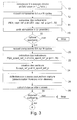
- the various distances between the vector to be tested (A or B on the Figure 4 ) and all the vectors of the learning base.
- K 3
- the majority class is assigned to the vector to be tested, the distribution being made between two classes.
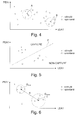
- the Figure 6 illustrates the simple case of space (LEA1, PEA1) divided into two half-spaces by a boundary F which is a straight line defining the boundary between the two capture / non-capture zones.
- a step of checking the interclass distance (block 28 on the Figure 3 ), so as to ascertain the truly discriminating character of the classification which has just been established.
- EP 1 080 744 A1 EA Medical
- EP 1 080 744 A1 EA Medical
- the algorithms described in this document can be implemented using as a capture test that of the invention, by analysis of the morphology of the EA signal in place of an electrical detection of the depolarization of the ventricle.
- biventricular pacing requires readjustment of DVV interventricular delay at regular intervals.
- This readjustment of the DVV is often done by scanning the delay between a minimum DVV and a maximum DVV, in order to search for the maximum of a hemodynamic parameter during this scan, maximum corresponding to the optimum of the DVV.
- the modification can also be carried out by a simple change of value of the DVV.
Abstract
Description
L'invention concerne les "dispositifs médicaux implantables actifs" tels que définis par la directive 90/385/CEE du 20 juin 1990 du Conseil des communautés européennes, plus précisément les implants permettant de surveiller en continu le rythme cardiaque et délivrer si nécessaire au coeur des impulsions électriques de stimulation, de resynchronisation et/ou de défibrillation en cas de trouble du rythme détecté par le dispositif.The invention relates to "active implantable medical devices" as defined by the Council of European Communities Directive 90/385 / EEC of 20 June 1990, more specifically implants for continuously monitoring the heart rate and delivering if necessary to the heart. electrical pacing, resynchronization and / or defibrillation pulses in case of rhythm disturbance detected by the device.
Ces dispositifs comprennent des moyens de stimulation ventriculaire, aptes à délivrer des impulsions de faible énergie à diverses électrodes implantées dans le ventricule droit et/ou le ventricule gauche.These devices comprise ventricular pacing means capable of delivering low energy pulses to various electrodes implanted in the right ventricle and / or the left ventricle.
Après la délivrance de l'impulsion, il est important de recueillir l"'onde évoquée", c'est-à-dire l'onde de dépolarisation induite par la stimulation du ventricule, afin de déterminer si cette stimulation a été efficace ou non. Ce test, dit "test de capture" est notamment utilisé pour évaluer le "seuil d'entraînement", c'est-à-dire le niveau minimal d'énergie de stimulation nécessaire pour provoquer la dépolarisation du ventricule. Il convient en effet d'ajuster l'amplitude et/ou la largeur de l'impulsion de stimulation afin, d'une part, de garantir que toute stimulation provoquera une onde évoquée et que, d'autre part, l'énergie délivrée ne sera pas excessive pour ne pas trop obérer la durée de vie de l'implant du fait d'une consommation excessive.After the delivery of the pulse, it is important to collect the "evoked wave", ie the depolarization wave induced by ventricular pacing, to determine whether this stimulation was effective or not. . This test, called "capture test" is used in particular to evaluate the "training threshold", that is to say the minimum level of stimulation energy needed to cause depolarization of the ventricle. It is indeed necessary to adjust the amplitude and / or the width of the stimulation pulse so as, on the one hand, to guarantee that any stimulation will cause an evoked wave and that, on the other hand, the energy delivered will not will not be excessive not to overburden the life of the implant due to excessive consumption.
Le test de capture est également un aspect important pour la surveillance du fonctionnement des dispositifs dits "CRT" (Cardiac Resynchronisation Therapy), qui sont des dispositifs munis d'électrodes permettant de stimuler l'un et l'autre ventricule. Le dispositif est capable de surveiller le rythme cardiaque et délivrer si besoin des impulsions permettant de stimuler conjointement les ventricules gauche et droit afin de resynchroniser ces derniers.The capture test is also an important aspect for monitoring the operation of so-called "CRT" devices (Cardiac Resynchronization Therapy), which are devices with electrodes for stimulating both ventricles. The device is able to monitor the heart rate and deliver pulses if necessary to jointly stimulate the left and right ventricles to resynchronize them.
Ces stimulations respectives sont appliquées avec un délai interventriculaire variable, positif ou négatif, ajusté de manière à resynchroniser la contraction des ventricules et optimiser l'état hémodynamique du patient. Le test de capture doit permettre de s'assurer que la stimulation est bien effective sur l'un et l'autre des deux ventricules, car il s'agit là d'une condition essentielle de la resynchronisation de ces derniers. Or on constate généralement des seuils d'entraînement différents entre le site droit et le site gauche, ce qui peut conduire à une stimulation défectueuse. Le dispositif peut en outre opérer une détection erronée des ondes de dépolarisation par confusion entre une dépolarisation électrostimulée à l'endroit du site analysé, et une dépolarisation en provenance du site voisin captée indirectement.These respective stimulations are applied with a variable interventricular delay, positive or negative, adjusted so as to resynchronize the contraction of the ventricles and optimize the hemodynamic state of the patient. The capture test must make sure that the stimulation is effective on both ventricles, because this is an essential condition of the resynchronization of the latter. However, there are generally different training thresholds between the right site and the left site, which can lead to defective stimulation. The device can furthermore operate an erroneous detection of the depolarization waves by confusion between an electrostimulated depolarization at the site of the analyzed site, and a depolarization coming from the neighboring site indirectly sensed.
Enfin, toute modification du délai interventriculaire peut avoir pour conséquence une modification des paramètres de la capture, de sorte qu'il est indispensable de suivre de manière très précise le fonctionnement du dispositif à chaque ajustement de ce paramètre, pour s'assurer que la thérapie de resynchronisation sera toujours efficace.Finally, any modification of the interventricular delay may result in a change in the parameters of the capture, so it is essential to follow very accurately the operation of the device at each adjustment of this parameter, to ensure that the therapy Resynchronization will still be effective.
Il existe de nombreuses techniques pour procéder au test de capture ventriculaire.There are many techniques for performing ventricular capture testing.
Les techniques usuelles, décrites par exemple dans les
Plus récemment, il a été proposé de tester la capture à partir d'un signal délivré par un capteur détectant directement la contraction mécanique du myocarde, ce qui permet d'obtenir immédiatement une information sur la réponse du ventricule à la stimulation, en faisant abstraction des périodes de blanking et autres limitations inhérentes au recueil d'un signal électrique. En d'autres termes, il s'agit d'utiliser un signal fonctionnel représentatif de la mécanique cardiaque, à la place d'un signal issu de la propagation électrique de l'onde de dépolarisation.More recently, it has been proposed to test the capture from a signal delivered by a sensor directly detecting the mechanical contraction of the myocardium, which makes it possible to immediately obtain information on the response of the ventricle to the stimulation, disregarding blanking periods and other limitations inherent in the collection of an electrical signal. In other words, it is a question of using a functional signal representative of cardiac mechanics, in the place of a signal resulting from the electrical propagation of the depolarization wave.
Ainsi, le
Le
Pour cela, le dispositif mesure (par une méthode des moindres carrés appliquée aux échantillons successivement recueillis sur une fenêtre temporelle prédéterminée) les distances euclidiennes entre, d'une part, le signal d'impédance recueilli après chaque double stimulation et, d'autre part, cinq templates (gabarits) de référence correspondant chacun à l'une des cinq situations prédéterminées suivantes : capture sur les deux ventricules ; capture sur le ventricule gauche seulement ; capture sur le ventricule droit seulement ; perte de capture sur les deux ventricules ; conduction intrinsèque en l'absence de stimulation. Les cinq distances ainsi évaluées sont comparées à des seuils de distance respectifs, pour décider de la classification des captures/pertes de capture.For this, the device measures (by a least squares method applied to samples successively collected over a predetermined time window) the Euclidean distances between, on the one hand, the impedance signal collected after each double stimulation and, on the other hand , five templates (templates) each corresponding to one of five predetermined situations: capture on both ventricles; capture on the left ventricle only; capture on the right ventricle only; loss of capture on both ventricles; intrinsic conduction in the absence of stimulation. The five distances thus evaluated are compared with respective distance thresholds to decide on the classification of catch / loss of catch.
Cette technique présente l'inconvénient de ce que la décision sur l'existence et la configuration des captures est prise en référence à une distance, valeur qui doit être relativisée et adaptée (à partir de quelle valeur considère-t-on que le signal est conforme à l'un des gabarits ?), les seuils auxquels sont comparées les distances euclidiennes étant des paramètres fortement patient-dépendants.This technique has the disadvantage that the decision on the existence and the configuration of the catches is taken with reference to a distance, a value that must be relativised and adapted (from what value do we consider that the signal is according to one of the templates?), the thresholds at which Euclidean distances are compared are highly patient-dependent parameters.
Un autre inconvénient de cette technique tient au fait que, comme cela arrive souvent dans le domaine biomédical, les signaux comparés deux à deux (signal recueilli vs. gabarits) ne sont pas des signaux synchrones. De ce fait, si l'on calcule une distance entre deux signaux décalés, même d'une faible valeur (par exemple de 5 ms), un biais très important peut être introduit dans le calcul de la distance, biais qui reste présent quand bien même les deux signaux seraient absolument identiques, et qui faussera donc la mesure et donc le résultat du test de capture.Another disadvantage of this technique is that, as often happens in the biomedical field, the signals compared two by two (collected signal vs. templates) are not synchronous signals. Therefore, if we calculate a distance between two offset signals, even of a small value (for example 5 ms), a very important bias can be introduced in the calculation of the distance, bias which remains present when well even the two signals would be absolutely identical, which will therefore distort the measurement and therefore the result of the capture test.
Le
Le
L'un des buts de l'invention est de proposer une nouvelle technique de détection de capture qui pallie ces inconvénients, notamment une technique :
- qui permette de prendre une décision sur une base qui ne soit pas patient-dépendante ;
- qui soit insensible aux décalages temporels, même importants, susceptibles d'affecter les signaux à comparer ;
- qui soit applicable indifféremment à la détection d'une capture sur un ventricule isolé (aussi bien droit que gauche) qu'à une détection de capture biventriculaire (pour un dispositif CRT) ; et
- qui puisse être implémentée avec des ressources logicielles relativement modestes, donc qui puisse être mise en oeuvre au sein même du dispositif implanté et en temps réel.
- to make a decision on a non-patient-dependent basis;
- which is insensitive to time offsets, even important, likely to affect the signals to be compared;
- which is equally applicable to the detection of a capture on an isolated ventricle (both right and left) and to a biventricular capture detection (for a CRT device); and
- which can be implemented with relatively modest software resources, so that it can be implemented within the implanted device and in real time.
La technique de l'invention est basée sur l'analyse de l'accélération endocardiaque (ci-après désignée "EA"), qui est un paramètre qui reflète très précisément et en temps réel les phénomènes concourant au fonctionnement mécanique du myocarde et qui peut être mesuré par un accéléromètre couplé au muscle cardiaque, comme cela est décrit par exemple dans le
On notera toutefois que, bien que dans la présente description on fasse principalement référence à l'analyse d'un signal EA délivré par un capteur placé sur une sonde endocavitaire, l'invention est également applicable à une analyse opérée à partir d'un signal EA délivré par d'autres types de capteurs implantés, tels qu'un capteur de mouvement d'une paroi du myocarde, un capteur épicardique ou un accéléromètre placé dans le boîtier d'un implant. L'invention est également applicable à l'analyse d'un signal EA externe recueilli de manière non invasive, par exemple issu d'un capteur fixé sur la poitrine du patient au niveau du sternum.It will be noted, however, that although in the present description reference is made mainly to the analysis of an EA signal delivered by a sensor placed on an endocavity probe, the invention is also applicable to an analysis performed on the basis of a signal EA delivered by other types of implanted sensors, such as a motion sensor of a myocardial wall, an epicardial sensor or an accelerometer placed in the housing of an implant. The invention is also applicable to the analysis of an external EA signal collected non-invasively, for example from a sensor attached to the breast of the patient at the sternum.
Le signal d'accélération endocardiaque EA recueilli au cours d'un cycle cardiaque donné (ci-après "signal EA") forme deux composantes principales (ci-après "composantes EA"), correspondant aux deux bruits majeurs du coeur (sons S1 et S2 du phonocardiogramme) qu'il est possible de reconnaître dans chaque cycle cardiaque :
- la première composante d'accélération endocardiaque ("composante EA1 "), dont les variations d'amplitude sont étroitement liées aux variations de la pression dans le ventricule (l'amplitude maximale crête-à-crête, appelée "PEA1", de cette composante EA1 étant plus précisément corrélée au maximum positif de la variation de pression dP/dt dans le ventricule gauche) et peuvent donc constituer un paramètre représentatif de la contractilité du myocarde, elle-même liée au niveau d'activité du système sympathique ;
- la seconde composante d'accélération endocardiaque ("composante EA2") qui, quant à elle, survient pendant la phase de relaxation ventriculaire isovolumique. Cette seconde composante est principalement produite par la fermeture des valves aortiques et pulmonaires.
- the first component of endocardial acceleration ("component EA1"), the amplitude variations of which are closely related to the variations in the pressure in the ventricle (the maximum peak-to-peak amplitude, called "PEA1", of this component EA1 being more precisely correlated with the positive maximum of the pressure variation dP / dt in the left ventricle) and can therefore constitute a representative parameter of the contractility of the myocardium, itself related to the level of activity of the sympathetic system;
- the second component of endocardial acceleration ("component EA2") which, in turn, occurs during the isovolumic ventricular relaxation phase. This second component is mainly produced by the closure of the aortic and pulmonary valves.
Plus précisément, l'invention propose un dispositif médical implantable actif comportant de manière en elle-même connue, par exemple d'après le
De façon caractéristique de l'invention, les moyens d'analyse du signal EA comprennent des moyens aptes à : isoler dans le signal EA au moins une composante EA d'accélération endocardiaque correspondant au premier et/ou au second bruit majeur du coeur, cette composante EA décrivant la variation continue du signal EA dans une fenêtre temporelle bornée correspondant à une fraction d'un cycle cardiaque ; extraire de la composante EA ainsi isolée n indicateurs, avec n ≥ 2, représentatifs du signal EA ; et former un vecteur EA de dimension n à partir des indicateurs ainsi extraits.In characteristic manner of the invention, the means for analyzing the signal EA comprise means able to: isolate in the signal EA at least one endocardial acceleration component EA corresponding to the first and / or second major noise of the heart, this EA component describing the continuous variation of the EA signal in a bounded time window corresponding to a fraction of a cardiac cycle; extract from the component EA thus isolated n indicators, with n ≥ 2, representative of the signal EA; and forming an EA vector of dimension n from the indicators thus extracted.
Le dispositif comprend en outre des moyens classificateurs pour, au cours d'une phase préalable : acquérir une pluralité de signaux EA à un niveau d'énergie de stimulation suffisamment élevé pour provoquer une capture et former une pluralité correspondante de premiers vecteurs EA de référence ; acquérir une pluralité de signaux EA en rythme spontané du patient en l'absence de stimulation ventriculaire et former une pluralité correspondante de seconds vecteurs EA de référence ; et à partir des premiers et seconds vecteurs ainsi acquis, partitionner l'espace de dimension n des vecteurs EA en deux sous-espaces correspondant respectivement à la présence et à l'absence d'une capture.The device further comprises classifying means for, during a prior phase: acquiring a plurality of EA signals at a sufficiently high stimulation energy level to cause capture and form a corresponding plurality of first reference EA vectors; acquiring a plurality of spontaneous rhythm EA signals of the patient in the absence of ventricular pacing and forming a corresponding plurality of second reference EA vectors; and from the first and second vectors thus acquired, partitioning the n-dimensional space of the vectors EA into two subspaces respectively corresponding to the presence and the absence of a capture.
Enfin, les moyens de test de capture ventriculaire comprennent des moyens aptes à : acquérir au moins un signal EA à un niveau courant d'énergie de stimulation et former au moins un vecteur EA courant correspondant ; et discriminer la présence ou l'absence d'une capture en fonction de la position du vecteur EA courant dans ledit espace de dimension n des vecteurs EA, respectivement dans l'un ou l'autre desdits deux sous-espaces.Finally, the ventricular capture test means comprise means capable of: acquiring at least one signal EA at a current level of stimulation energy and forming at least one corresponding current vector EA; and discriminating the presence or absence of a capture as a function of the position of the vector EA current in said n-dimensional space of the vectors EA, respectively in one or the other of said two subspaces.
Les n indicateurs représentatifs du signal EA peuvent notamment être choisis parmi : la valeur de l'amplitude crête-à-crête, la largeur, l'instant de survenue du pic, l'instant de début, et l'instant de fin de la composante EA1.The n representative indicators of the signal EA can be chosen in particular from: the value of the peak-to-peak amplitude, the width, the time of occurrence of the peak, the start time, and the end time of the EA1 component.
Subsidiairement, il est également possible de choisir des indicateurs de morphologie parmi : le rapport signal sur bruit, la valeur de contraste, la valeur d'entropie, et l'énergie cumulée de la composante EA1. En variante ou en complément, il est également possible de choisir des indicateurs de morphologie parmi : la valeur de l'amplitude crête-à-crête, la largeur, l'instant de survenue du pic, l'instant de début, et l'instant de fin de la composante EA2, et/ou la valeur de l'amplitude crête-à-crête de la composante EA 4.Alternatively, it is also possible to choose morphology indicators from: the signal-to-noise ratio, the contrast value, the entropy value, and the cumulative energy of the EA1 component. As a variant or in addition, it is also possible to choose morphology indicators from among: the value of the peak-to-peak amplitude, the width, the time of occurrence of the peak, the start time, and the end time of the component EA2, and / or the value of the peak-to-peak amplitude of the component EA 4.
Dans un mode de réalisation préférentiel, n = 2 et les deux indicateurs représentatifs du signal EA sont la valeur de l'amplitude crête-à-crête et la largeur de la composante EA1.In a preferred embodiment, n = 2 and the two representative indicators of the signal EA are the value of the peak-to-peak amplitude and the width of the component EA1.
Selon diverses caractéristiques subsidiaires avantageuses:
- les moyens de test de capture ventriculaire comprennent des moyens aptes à former une pluralité de vecteurs EA courants, et à discriminer la présence ou l'absence d'une capture par application d'un critère majoritaire ;
- les moyens pour partitionner ledit espace de dimension n des vecteurs EA en deux sous-espaces comprennent des moyens pour appliquer un critère de seuil séparément à chacun des indicateurs des vecteurs EA, ou bien des moyens de mise en oeuvre d'un algorithme de classification du groupe : K plus proches voisins, réseau de neurones, et classification linéaire par estimation de la matrice pseudo-inverse ;
- les moyens classificateurs comprennent en outre des moyens d'évaluation d'une distance inter-classes et de vérification d'une distance minimale;
- le dispositif comprend des moyens de stimulation auriculaire, activables à une fréquence de stimulation fixe prédéterminée lors de la mise en oeuvre des moyens classificateurs et des moyens de test de capture ventriculaire ;
- le dispositif comprend des moyens de recherche du seuil de capture ventriculaire, aptes à modifier de manière itérative le niveau d'énergie de l'impulsion de stimulation, et à tester à chaque fois la présence ou l'absence d'une capture ;
- le dispositif comporte des moyens de stimulation conjointe des deux ventricules, droit et gauche avec application d'un délai interventriculaire entre les instants respectifs de stimulation des ventricules droit et gauche, les moyens de test de capture sont des moyens aptes à détecter la présence d'un capture sur les deux ventricules ; et le dispositif comporte des moyens pour activer les moyens de test de capture en réponse à toute variation ou modification du délai interventriculaire ;
- le capteur d'accélération est un capteur du groupe formé par : capteur endocavitaire ; capteur épicardique ; capteur externe.
- the ventricular capture test means comprise means capable of forming a plurality of current EA vectors, and of discriminating the presence or the absence of a capture by application of a majority criterion;
- the means for partitioning said n-dimensional space of the EA vectors into two subspaces comprises means for applying a threshold criterion separately to each of the EA vector indicators, or means for implementing a classification algorithm of the EA vectors; group: K nearest neighbors, neural network, and linear classification by estimation of the pseudo-inverse matrix;
- the classifying means further comprise means for evaluating an inter-class distance and for verifying a minimum distance;
- the device comprises atrial pacing means operable at a predetermined fixed pacing rate when implementing the classifying means and the ventricular capture testing means;
- the device comprises means for finding the ventricular capture threshold, able to modify iteratively the energy level of the stimulation pulse, and to test each time the presence or absence of a capture;
- the device comprises means for conjoint stimulation of the two ventricles, right and left with application of an interventricular delay between the respective instants of stimulation of the right and left ventricles, the capture test means are means able to detect the presence of a capture on both ventricles; and the device comprises means for activating the capture test means in response to any variation or modification of the interventricular delay;
- the acceleration sensor is a sensor of the group formed by: endocavity sensor; epicardial sensor; external sensor.
On va maintenant décrire un exemple de mise en oeuvre de l'invention, en référence aux dessins annexés où les mêmes références numériques désignent d'une figure à l'autre des éléments identiques ou fonctionnellement semblables.
- La
Figure 1 montre les chronogrammes relevés au cours de trois cycles cardiaques successifs d'un signal d'accélération endocardiaque EA et d'un tracé d'électrocardiogramme ECG correspondant. - Les
Figures 2a et 2b montrent un exemple d'une composante EA, respectivement en présence d'un rythme stimulé avec capture et dans le cas d'un rythme spontané. - La
Figure 3 est un organigramme présentant sous forme de schéma par blocs les diverses étapes permettant d'obtenir une composante EA de référence, en présence d'une capture puis en rythme spontané. - Les
Figures 4 et 5 illustrent la position, dans un espace bidimensionnel, des divers points de mesure relevés pour des situations de rythme stimulé et spontané, expliquant deux manières possibles de partitionner cet espace en deux classes définissant la capture ou l'absence de capture. - La
Figure 6 illustre, toujours dans ce même espace à deux dimensions, l'étape de vérification de la distance séparant les classes précédemment définies. - La
Figure 7 est un organigramme présentant sous forme de schéma par blocs les étapes successives du test de capture selon la présente invention.
- The
Figure 1 shows the chronograms taken during three successive cardiac cycles of an EA endocardial acceleration signal and a corresponding ECG electrocardiogram plot. - The
Figures 2a and 2b show an example of an EA component, respectively in the presence of a stimulated rhythm with capture and in the case of a spontaneous rhythm. - The
Figure 3 is a flowchart showing in block diagram form the various steps for obtaining a reference component EA, in the presence of a capture and then in a spontaneous rhythm. - The
Figures 4 and 5 illustrate the position, in a two-dimensional space, of the various measurement points recorded for situations of stimulated and spontaneous rhythm, explaining two possible ways to partition this space into two classes defining the capture or the absence of capture. - The
Figure 6 illustrates, still in this same two-dimensional space, the step of checking the distance separating the previously defined classes. - The
Figure 7 is a block diagram showing in block diagram form the successive steps of the capture test according to the present invention.
On va maintenant décrire un exemple de mise en oeuvre de l'invention.We will now describe an example of implementation of the invention.
En ce qui concerne ses aspects logiciels, l'invention peut être mise en oeuvre par une programmation appropriée du logiciel de commande d'un stimulateur connu, par exemple de type stimulateur cardiaque, resynchroniseur et/ou défibrillateur, comprenant des moyens d'acquisition d'un signal fourni par des sondes endocavitaires et/ou un ou plusieurs capteurs implantés.With regard to its software aspects, the invention can be implemented by appropriate programming of the control software of a known pacemaker, for example of pacemaker, resynchronizer and / or defibrillator type, comprising means of acquisition of a signal provided by endocardial probes and / or one or more implanted sensors.
L'invention peut notamment être appliquée aux dispositifs implantables tels que ceux des familles Reply et Paradym produits et commercialisés par Sorin CRM, Clamart, France.The invention can in particular be applied to implantable devices such as those of the Reply and Paradym families produced and marketed by Sorin CRM, Clamart, France.
Il s'agit de dispositifs à microprocesseur programmable comportant des circuits pour recevoir, mettre en forme et traiter des signaux électriques recueillis par des électrodes implantées, et délivrer des impulsions de stimulation à ces électrodes. Il est possible d'y transmettre par télémétrie des logiciels qui seront conservés en mémoire et exécutés pour mettre en oeuvre les fonctions de l'invention qui seront décrites ci-dessous. L'adaptation de ces appareils à la mise en oeuvre des fonctions de l'invention est à la portée de l'homme du métier, et elle ne sera pas décrite en détail.These are programmable microprocessor devices having circuitry for receiving, shaping, and processing electrical signals collected by implanted electrodes, and providing pacing pulses to these electrodes. It is possible to transmit there by telemetry software which will be stored in memory and executed to implement the functions of the invention which will be described below. The adaptation of these devices to the implementation of the functions of the invention is within the abilities of those skilled in the art, and it will not be described in detail.
Comme on l'a indiqué plus haut, le signal d'accélération endocardiaque EA recueilli au cours d'un cycle cardiaque forme deux composantes principales, correspondant aux deux bruits majeurs du coeur (sons S1 et S2 du phonocardiogramme) qu'il est possible de reconnaître dans chaque cycle cardiaque :
- la composante EA1, dont les variations d'amplitude sont étroitement liées aux variations de la pression dans le ventricule (l'amplitude maximale crête-à-crête, appelée "PEA1", de cette composante EA1 étant plus précisément corrélée au maximum positif de la variation de pression dP/dt dans le ventricule gauche) ;
- la composante EA2 qui survient pendant la phase de relaxation ventriculaire isovolumique et qui est principalement produite par la fermeture des valves aortiques et pulmonaires.
- the component EA1, whose amplitude variations are closely related to the variations in the pressure in the ventricle (the maximum peak-to-peak amplitude, called "PEA1", of this component EA1 being more precisely correlated with the positive maximum of the pressure variation dP / dt in the left ventricle);
- the EA2 component that occurs during the isovolumic ventricular relaxation phase and is mainly produced by the closure of the aortic and pulmonary valves.
Le signal EA contient parfois une ou deux autres composantes, appelées EA3 et EA4, correspondant aux sons S3 et S4 du phonocardiogramme.The signal EA sometimes contains one or two other components, called EA3 and EA4, corresponding to the sounds S3 and S4 of the phonocardiogram.
Ce signal EA est illustré
Le traitement préliminaire de la composante EA implique, tout d'abord, d'individualiser les cycles cardiaques successifs dans le signal EA recueilli en continu, en déterminant des marqueurs de début de cycle permettant de séparer ces cycles et d'isoler une série de sous-signaux EA bornés dans le temps correspondant chacun à une durée d'un seul cycle cardiaque :
- dans le cas d'un signal EA endocavitaire, les marqueurs temporels de début de cycle sont fournis par l'implant lui-même, qui selon le mode de fonctionnement garde en mémoire les instants de la stimulation V, (comme illustré
Figure 1 ) ou bien les instants de détection de l'onde R ; - dans le cas d'un signal EA externe, les marqueurs temporels de début de cycle cardiaque sont fournis par un algorithme de détection des pics de stimulation ou des complexes QRS du signal ECG, signal recueilli par ailleurs au moyen d'électrodes externes.
- in the case of an endocavitary EA signal, the time markers of the beginning of the cycle are provided by the implant itself, which according to the operating mode keeps in memory the instants of the stimulation V, (as illustrated
Figure 1 ) or the instants of detection of the wave R; - in the case of an external EA signal, the time markers of the beginning of the cardiac cycle are provided by an algorithm for detecting stimulation peaks or QRS complexes of the ECG signal, a signal also collected by means of external electrodes.
L'étape suivante consiste à isoler la composante EA1 et/ou la composante EA2 dans chacun des sous-signaux bornés dans le temps correspondant à un cycle cardiaque.The next step is to isolate the component EA1 and / or component EA2 in each of the sub-signals bounded in the time corresponding to a cardiac cycle.
Dans la description qui va suivre, on s'intéressera principalement à la composante EA1, car c'est celle-ci qui est la plus caractéristique.In the description that follows, we will focus primarily on the component EA1, because it is the latter that is most characteristic.
Mais les enseignements de l'invention sont transposables aussi bien à l'analyse de la composante EA2, en variante ou en complément de la composante EA1.But the teachings of the invention can be transposed as well to the analysis of the EA2 component, alternatively or in addition to the EA1 component.
Chacune de ces "composantes" EA1 et EA2 sera représentée par un ensemble de valeurs successives décrivant la variation continue du "signal" EA dans une fenêtre temporelle donnée s'étendant autour du "pic" PEA1 (ou PEA2), sur une fraction de la durée d'un cycle cardiaque. Concrètement, chacune de ces composantes sera constituée d'un sous-ensemble de la matrice des N échantillons du signal EA obtenus après numérisation de celui-ci sur la durée du cycle cardiaque.Each of these "components" EA1 and EA2 will be represented by a set of successive values describing the continuous variation of the "signal" EA in a given time window extending around the "peak" PEA1 (or PEA2), over a fraction of the duration of a cardiac cycle. Specifically, each of these components will consist of a subset of the matrix of N samples of the EA signal obtained after digitization of the latter over the duration of the cardiac cycle.
Chacune de ces composantes représente donc une fraction du signal EA sur la durée d'un cycle cardiaque, et chaque cycle cardiaque sera constitué d'une pluralité de "composantes" qui se succéderont, notamment les deux premières composantes EA1 et EA2, ces composantes étant également suivies des composantes secondaires EA3 et EA4.Each of these components therefore represents a fraction of the EA signal over the duration of a cardiac cycle, and each cardiac cycle will consist of a plurality of "components" which will follow one another, in particular the first two components EA1 and EA2, these components being also followed by secondary components EA3 and EA4.
De préférence, la composante EA1 (et/ou EA2) du signal EA est déterminée avec un moyennage sur plusieurs cycles, typiquement trois à cinq cycles, en appliquant une technique telle que celle exposée dans la demande
Essentiellement, cette technique consiste à effectuer un prétraitement du signal EA recueilli en continu, avec :
- découpage du signal EA en sous-signaux correspondant chacun à la durée d'un cycle cardiaque et repérés par un marqueur de début de cycle permettant de réaliser ce découpage ;
- segmentation de chacun de ces sous-signaux de manière à individualiser une ou plusieurs des composantes EA1 et/ou EA2 dans une fenêtre temporelle donnée ;
- pour la composante courante EA1 ou EA2 ainsi isolée sur un cycle, recherche d'un pic d'intercorrélation par rapport aux composantes EA1 (ou EA2) des autres cycles recueillis ;
- calcul d'un décalage temporel correspondant ; et
- application du décalage temporel ainsi calculé à la composante courante, de manière à aligner celle-ci par rapport aux autres.
- splitting the signal EA into sub-signals each corresponding to the duration of a cardiac cycle and identified by a start-of-cycle marker for performing this division;
- segmenting each of these sub-signals so as to individualize one or more of the components EA1 and / or EA2 in a given time window;
- for the current component EA1 or EA2 thus isolated on one cycle, looking for a cross-correlation peak with respect to the EA1 (or EA2) components of the other cycles collected;
- calculating a corresponding time offset; and
- applying the time offset thus calculated to the current component, so as to align it with the others.
Les traitements d'analyse pourront être ensuite exécutés sur ces composantes EA1 (et/ou EA2) successives, avec élimination du biais de la variabilité cycle à cycle grâce à ce prétraitement.The analysis treatments can then be performed on these components EA1 (and / or EA2) successive, eliminating the bias of the cycle-to-cycle variability through this pretreatment.
Cette phase initiale de la méthode de l'invention vise à déterminer préalablement un critère de distinction permettant de reconnaître la présence ou l'absence d'une capture, par définition de deux classes correspondantes qui seront ensuite utilisées pour le test de capture proprement dit : selon que les valeurs courantes relevées au cours d'un cycle cardiaque appartiendront à l'une ou l'autre de ces deux classes, on considèrera qu'il y a présence ou absence d'une capture.This initial phase of the method of the invention aims to determine beforehand a distinction criterion making it possible to recognize the presence or the absence of a capture, by definition of two corresponding classes which will then be used for the actual capture test: depending on whether the current values recorded during a cardiac cycle will belong to one or the other of these two classes, it will be considered that there is presence or absence of a capture.
Ces classes sont définies par une partition d'un espace de dimension N en deux sous-espaces, l'un correspondant à une situation de capture, l'autre à une situation de non-capture.These classes are defined by a partition of a space of dimension N in two subspaces, one corresponding to a situation of capture, the other to a situation of non-capture.
Les N dimensions correspondent chacune à un indicateur caractéristique de la composante EA.The N dimensions each correspond to a characteristic indicator of the EA component.
Pour la clarté et la simplicité de l'exposé, on ne fera référence comme "composante EA" qu'à la composante "EA1 ", mais tout ce qui sera dit à propos de cette composante "EA1" doit être considéré comme applicable mutatis mutandis à la composante EA2 et même, éventuellement, aux composantes EA3 et/ou EA4.For the clarity and simplicity of the presentation, only "EA1" will be referred to as "EA component", but anything said about this "EA1" component should be considered mutatis mutandis to component EA2 and even possibly to components EA3 and / or EA4.
On entendra par "indicateur" une grandeur mesurable de la composante EA, obtenue par analyse du signal EA dans une fenêtre temporelle bornée correspondant à une fraction d'un cycle cardiaque comprenant cette composante EA. L'indicateur sera exprimé sous la forme d'une valeur mesurée unique, c'est-à-dire d'un scalaire. Chacun des indicateurs est choisi pour pouvoir caractériser par la valeur qu'il prend l'absence ou la présence d'une capture.By "indicator" is meant a measurable magnitude of the component EA, obtained by analysis of the signal EA in a bounded time window corresponding to a fraction of a cardiac cycle comprising this component EA. The indicator will be expressed as a single measured value, that is, a scalar. Each of the indicators is chosen to be able to characterize by the value that it takes the absence or the presence of a catch.
Concrètement, l'analyse d'un seul de ces indicateurs (par exemple la valeur PEA1 de l'amplitude crête à crête de la composante EA1) n'est pas suffisante pour discriminer de façon fiable entre présence et absence d'une capture, et conduirait à un nombre trop important de déterminations erronées, avec aussi bien des faux positifs que des faux négatifs.Specifically, the analysis of only one of these indicators (for example the PEA1 value of the peak-peak amplitude of the component EA1) is not sufficient to reliably discriminate between presence and absence of a capture, and lead to too many erroneous determinations, with both false positives and false negatives.
C'est pourquoi l'invention propose d'utiliser une pluralité d'indicateurs différents (au moins deux), caractérisant une même composante EA recueillie au cours d'un battement cardiaque donné, et de combiner entre eux ces indicateurs, de la manière que l'on exposera, pour décider entre présence ou absence d'une capture avec un degré de fiabilité supérieur.This is why the invention proposes to use a plurality of different indicators (at least two), characterizing the same EA component collected during a given heartbeat, and to combine these indicators with each other, in the way that we will expose, to decide between presence or absence of a capture with a higher degree of reliability.
On appellera ci-après "vecteur" l'ensemble des valeurs de ces divers indicateurs obtenues pour une composante EA1 donnée d'un battement cardiaque (cette composante ayant été éventuellement moyennée sur plusieurs cycles successifs, comme on l'a exposé plus haut).Hereinafter referred to as "vector", the set of values of these various indicators obtained for a given EA1 component of a heartbeat (this component having possibly been averaged over several successive cycles, as explained above).
Dans l'exemple qui va suivre, on prendra l'exemple le plus simple, d'un vecteur de dimension N = 2, avec les deux indicateurs suivants, qui permettent de décrire simplement la morphologie de la composante EA1 d'une manière très différente selon qu'il y a ou non capture :
- la valeur PEA1 de l'amplitude crête-à-crête de la composante EA1 sur la fenêtre d'analyse considérée, par exemple sur la fenêtre [0-300 ms], l'origine des temps (0 ms) correspondant à l'instant de la stimulation ventriculaire la plus tardive, et
- la valeur LEA1 de la "largeur" de la composante EA1, c'est-à-dire la durée de celle-ci.
- the PEA1 value of the peak-to-peak amplitude of the component EA1 on the analysis window considered, for example on the window [0-300 ms], the origin of the times (0 ms) corresponding to the moment the latest ventricular pacing, and
- the value LEA1 of the "width" of the component EA1, that is to say the duration thereof.
Ces indicateurs sont illustrés notamment
En ce qui concerne plus précisément l'indicateur LEA1, celui-ci peut être obtenu en seuillant une enveloppe d'énergie NRG obtenue en élevant au carré la valeur des échantillons de signal, puis en appliquant une fenêtre de lissage de 100 ms par exemple. L'instant de début tstart et l'instant de fin tend de début et de fin de la composante EA (avec LEA1 = tend - tstart) correspondent au franchissement d'un seuil qui peut être par exemple 10 % du maximum de l'énergie NRG sur la fenêtre [0-300 ms]. Cette méthode de détermination des instants caractéristiques de la composante EA1 est décrite, ainsi que d'autres, dans le
Chacun des couples de valeurs {PEA1, LEA1} constitue un vecteur représentatif de la composante EA1 analysée, vecteur qui peut être représentée graphiquement par un point dans le plan (PEA1, LEA1), comme illustré
L'exemple que l'on décrit avec N = 2 et où les indicateurs sont PEA1 et LEA1 n'est aucunement limitatif, et il est possible d'opérer l'analyse sur des vecteurs de dimension N > 2 incluant d'autres indicateurs, en variante ou en complément. Ainsi, parmi les indicateurs représentatifs, on peut utiliser notamment des indicateurs temporels tels que :
- l'instant de survenue du pic de la composante EA1, compté par rapport à l'origine de la fenêtre d'analyse [0-300 ms]. Cet instant peut être notamment calculé comme étant la moyenne des deux instants tm d'occurrence du pic minimum et tM du pic maximum du signal EA de la composante EA1 (cf.
Figures 2a et 2b ) ; - les instants de début et/ou de fin tstart et tend, respectivement, de la composante EA1 (voir ci-dessus la manière dont ces instants sont définis) ;
- l'instant du maximum de l'enveloppe énergétique tmaxNRG; et
- les mêmes instants, pour la composante PEA2.
- the moment of occurrence of the peak of component EA1, counted relative to the origin of the analysis window [0-300 ms]. This instant may in particular be calculated as the average of the two instants t m of occurrence of the minimum peak and t M of the maximum peak of the signal EA of the component EA1 (cf.
Figures 2a and 2b ); - the start and / or end times t start and t end , respectively, of the component EA1 (see above how these times are defined);
- the moment of the maximum of the energy envelope t maxNRG ; and
- the same moments, for the PEA2 component.
Il est également possible de choisir des indicateurs représentatifs de la morphologie de la composante EA1 tels que :
- le rapport signal sur bruit SNR, qui peut être défini par :

σ_noise étant l'écart-type du signal considéré comme "bruit", c'est-à-dire le signal contenu dans la fenêtre de signal utile EA2, à l'exception du segment [tEA2_start, tEA2_end ] correspondant à la composante EA2 proprement dite ; - la valeur de contraste, donnée par une formule telle que :

σEA1_window étant l'écart-type du signal contenu dans la fenêtre [0, 300 ms] ; - la valeur d'entropie, donnée par une formule telle que :

- the signal-to-noise ratio SNR, which can be defined by:
σ_noise being the standard deviation of the signal considered as "noise", that is to say the signal contained in the useful signal window EA2, with the exception of the segment [ t EA2_start, tE A2_end ] corresponding to the component EA2 proper; - the contrast value, given by a formula such as:
σ EA1 _ window being the standard deviation of the signal contained in the window [0, 300 ms]; - the entropy value, given by a formula such as:
Cette quantité reflète le "degré d'ordre" du signal : si le signal est proche d'un bruit blanc l'entropie sera élevée, si au contraire il est "ordonné", l'entropie sera plus faible.
- l'énergie cumulée, calculée à partir de l'aire sous la courbe d'enveloppe énergétique NRG.
- cumulative energy, calculated from the area under the NRG energy envelope curve.
D'autres indicateurs caractéristiques peuvent être également utilisés en complément, tels que :
- les valeurs des amplitudes caractéristiques de la composante EA4, notamment l'amplitude crête-à-crête sur la fenêtre [- 200 ms, 0 ms].
- the values of the characteristic amplitudes of the component EA4, in particular the peak-to-peak amplitude on the window [- 200 ms, 0 ms].
On sait en effet que la composante EA4 arrive entre le début de l'activité auriculaire (l'onde P dans le cas d'un ECG, ou la détection de la dépolarisation sur la sonde auriculaire dans le cas d'un dispositif implantable) et le début de la composante EA1. On pourra se référer au
La
Tout d'abord (bloc 10) le ventricule est stimulé dans des conditions permettant d'assurer la capture, avec une énergie de stimulation relativement élevée et un délai atrioventriculaire DAV court. Pour éviter les variations de rythme qui pourraient perturber le recueil de la composante EA, on peut également prévoir de stabiliser la fréquence cardiaque en stimulant le coeur par l'oreillette avec une fréquence fixe de stimulation auriculaire fstim.First (block 10) the ventricle is stimulated under conditions to ensure capture, with relatively high pacing energy and short AV atrioventricular delay. To avoid variations in rhythm that could disturb the collection of the EA component, it is also possible to stabilize the heart rate by stimulating the heart by the atrium with a fixed frequency of atrial stimulation stim .
La composante EA1 (et/ou EA2) est ensuite recueillie et moyennée sur N cycles (bloc 12), typiquement N = 5 cycles successifs, de la manière expliquée plus haut.The component EA1 (and / or EA2) is then collected and averaged over N cycles (block 12), typically N = 5 successive cycles, as explained above.
Les indicateurs qui ont été choisis sont alors extraits de la composante EA (bloc 14). Dans l'exemple plus haut où ces indicateurs sont l'amplitude PEA du pic et la longueur LEA de la composante EA1, ces indicateurs extraits sur les N = 5 cycles successifs seront : PEA_cap_ref_p et LEA_capt_ref_p (p = 1 ... 5).The indicators that have been chosen are then extracted from the EA component (block 14). In the example above where these indicators are the peak PEA amplitude and the length EAA EA1 component, these indicators extracted on the N = 5 successive cycles will be: PEA_cap_ref_p and LEA_capt_ref_p ( p = 1 ... 5).
On arrête alors la stimulation du ventricule (bloc 16), bien entendu si cela est possible (absence de bloc atrioventriculaire complet, notamment).The stimulation of the ventricle (block 16) is then stopped, of course if it is possible (absence of complete atrioventricular block, in particular).
On recherche ensuite (test 18) la présence d'un rythme spontané et, s'il est présent, on procède de la même façon que précédemment au recueil de la composante EA sur N = 5 cycles et à l'extraction des indicateurs correspondants PEA_spont_ref_p et LEA_spont_ref_p (blocs 20 et 22, semblables aux blocs 12 et 14).The presence of a spontaneous rhythm is then sought (test 18) and, if it is present, one proceeds in the same way as previously to the collection of the component EA on N = 5 cycles and with the extraction of the corresponding indicators PEA_spont_ref_p and LEA_spont_ref_p (blocks 20 and 22, similar to
On forme alors les p vecteurs X_capt_ref_p et les p vecteurs X_spont_ref_p à partir des indicateurs préalablement extraits (bloc 24).The vectors X_capt_ref_p and the vectors X_spont_ref_p are then formed from the previously extracted indicators (block 24).
L'étape suivante (bloc 26) consiste à trouver une règle de séparation des vecteurs X_capt_ref_p et X_spont_ref_p en deux classes distinctes.The next step (block 26) is to find a rule of separation of the vectors X_capt_ref_p and X_spont_ref_p into two distinct classes.
Ces classes permettront ensuite, pour un nouveau vecteur X courant issu d'une nouvelle configuration de stimulation, de déterminer la présence ou l'absence d'une capture en fonction de la classification qui sera attribuée à ce nouveau vecteur courant.These classes will then make it possible, for a new current vector X resulting from a new stimulation configuration, to determine the presence or the absence of a catch according to the classification that will be attributed to this new current vector.
Plusieurs méthodes peuvent être appliquées pour cette définition de la règle de séparation en deux classes.Several methods can be applied for this definition of the separation rule into two classes.
Une première série de méthodes consiste à opérer séparément sur les deux indicateurs (c'est-à-dire sur les deux coordonnées du vecteur), par exemple au moyen de détecteurs simples à seuil, les seuils correspondant à chaque indicateur étant choisis pour obtenir un compromis sensibilité/sélectivité prédéterminé (par exemple : sensibilité > 90 % et spécificité > 95 %). Les deux tests sont ensuite combinés ensemble par un vote, par exemple une fonction ET logique.A first series of methods consists in operating separately on the two indicators (that is to say on the two coordinates of the vector), for example by means of simple threshold detectors, the thresholds corresponding to each indicator being chosen to obtain compromise sensitivity / selectivity predetermined (eg sensitivity> 90% and specificity> 95%). The two tests are then combined together by a vote, for example a logical AND function.
Une autre série de méthodes, préférentiellement utilisées, consiste à opérer directement sur les vecteurs à deux dimensions (ou plus généralement à N dimensions, dans le cas de N > 2 indicateurs extraits de la composante EA).Another series of methods, preferably used, consists in operating directly on the two-dimensional vectors (or more generally N-dimensions, in the case of N> 2 indicators extracted from the EA component).
Un vecteur donné peut être ainsi représenté graphiquement par un point de l'espace vectoriel, notamment par un point du plan (LEA1, PEA1) dans l'exemple donné ici, comme illustré
Une première méthode utilisable est la méthode dite "des K plus proches voisins" (KPPV), appliquée sur les vecteurs d'indicateurs, et illustrée
On calcule à cet effet les diverses distances entre le vecteur à tester (A ou B sur la
Une deuxième méthode utilisable consiste à mettre en oeuvre un réseau de neurones, appliqué au vecteur d'indicateurs. Après une phase d'apprentissage permettant d'ajuster les paramètres internes du réseau de neurones, chaque nouveau vecteur testé traité par le réseau de neurones se verra affecter en sortie une classe d'appartenance parmi les deux (dans le présent exemple) classes possibles. On pourra utiliser comme réseau de neurones un réseau de type perceptron, qui est un réseau classifieur linéaire simple à n entrées et une seule sortie. On pourra trouver plus de détails dans :
Une troisième méthode utilisable consiste à opérer une classification linéaire par estimation de la matrice pseudo-inverse. On définit le vecteur Classe prenant les valeurs (1, -1) si X appartient à la classe Cap_ref et (-1, 1) si X appartient à la classe Spont_ref. L'apprentissage consiste à calculer la matrice W qui permet de minimiser l'erreur quadratique moyenne suivante : 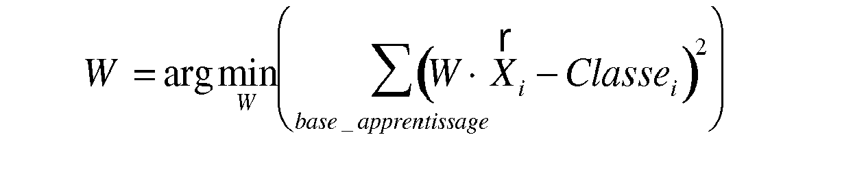
Les vecteurs Xi de la base d'apprentissage (de classe Classei ) sont les vecteurs X_spont_ref_p et X_capt_ref_p. Cette matrice W est donné par l'expression suivante : 
[x] étant la matrice résultant de la concaténation des vecteurs Xi : 
et [Classe] étant la matrice résultant de la concaténation des vecteurs Classei associés aux vecteurs Xi. The vectors X i of the learning base (class Class i ) are the vectors X_spont_ref_p and X_capt_ref_p. This matrix W is given by the following expression:
[ x ] being the matrix resulting from the concatenation of the vectors X i :
and [ Class ] being the matrix resulting from the concatenation of Class i vectors associated with X i vectors .
Pour déterminer la classe d'un vecteur à tester Y, il suffit de calculer le vecteur S = W x Y = (S1, S2). Chaque composante de ce vecteur de sortie est une valeur (comprise entre -1 et 1) que le classifieur accorde à chaque classe. Il suffit d'affecter à Y la classe associée à la valeur maximale (si c'est S1, Y appartient à la classe Capt_ref). To determine the class of a vector to be tested Y, it suffices to calculate the vector S = W x Y = ( S1, S2 ) . Each component of this output vector is a value (between -1 and 1) that the classifier assigns to each class. All you have to do is assign Y to the class associated with the maximum value (if it's S1, Y belongs to the class Capt_ref ) .
La
Mais selon l'approche retenue, la limite interzone peut être également formée par des segments de droite, un cercle, une parabole, ou toute autre forme géométrique. Cette limite peut aussi se traduire par une condition logique, par exemple dans le cas des KPPV, la condition d'appartenance d'un point X à une zone se déterminera en regardant la zone d'appartenance majoritaire des K points les plus proches de X.But depending on the approach chosen, the interzone boundary can also be formed by line segments, a circle, a parabola, or any other geometrical form. This limit can also result in a logical condition, for example in the case of KPPVs, the membership condition of a point X to a zone will be determined by looking at the majority belonging zone of the K points closest to X .
On peut aussi proposer à un utilisateur d'ajuster manuellement la limite, en la traçant ou en la déplaçant sur un graphe (pas obligatoirement une droite), ou en entrant les coordonnées de deux points appartenant à la limite, si cette limite est une droite.We can also propose to a user to manually adjust the limit, drawing it or moving it on a graph (not necessarily a line), or by entering the coordinates of two points belonging to the limit, if this limit is a straight line .
Avantageusement, une fois les deux classes déterminées, il est prévu une étape de vérification de la distance inter-classes (bloc 28 sur la
La distance inter-classes est définie comme la distance euclidienne entre les centres de gravité des deux zones capture/non-capture, et l'on vérifie que cette distance est suffisamment grande par rapport aux distances moyennes entre les éléments de chaque zone par rapport aux centres de gravité respectifs.The inter-class distance is defined as the Euclidean distance between the centers of gravity of the two capture / non-capture zones, and it is verified that this distance is sufficiently large compared to the mean distances between the elements of each zone with respect to respective centers of gravity.
Ceci est illustré notamment
Un autre critère consiste à calculer un ratio J, inspiré du critère discriminant de Fisher, constitué par le rapport entre la "distance entre les barycentres" (m 1 et m 2) et la "compacité des classes" (s 1 2+s 2 2): 
Ce critère augmente avec :
- la distance entre les projections des barycentres des casses, et avec
- la "compacité" des projections des classes.
- the distance between the projections of the barycentres of the breaks, and with
- the "compactness" of class projections.
Si le critère de distance suffisante inter-classes n'est pas vérifié, ceci signifie qu'il n'y a pas ou peu de différence entre le signal EA recueilli en stimulant le ventricule et le signal EA recueilli en rythme spontané. Cette situation peut être aussi la conséquence d'un problème lié à la sonde. Dans un tel cas, un test de capture n'aurait pas de sens, et il est mis fin au processus, avec éventuellement déclenchement d'une alarme.If the criterion of sufficient interclass distance is not verified, this means that there is little or no difference between the EA signal collected by stimulating the ventricle and the EA signal collected in spontaneous rhythm. This situation may also be the consequence of a problem with the probe. In such a case, a capture test would be meaningless, and the process is terminated, possibly triggering an alarm.
Dans le cas contraire, c'est-à-dire si les indicateurs relevés pour les signaux EA respectivement en stimulé et en spontané sont suffisamment différents, on peut procéder au test de capture, que l'on va maintenant décrire.In the opposite case, that is to say if the indicators recorded for the EA signals respectively stimulated and spontaneous are sufficiently different, we can proceed to the capture test, which will now be described.
Les différentes étapes de la phase de test de capture sont illustrées
On va décrire ce test de capture ventriculaire dans le cadre d'une recherche du seuil d'entraînement (seuil de stimulation ventriculaire). Cette recherche consiste à appliquer au ventricule des impulsions de stimulation à énergie V décroissante, en contrôlant à chaque fois sur le signal EA la présence ou non d'une contraction par la méthode que l'on va décrire.This ventricular capture test will be described as part of a search for the training threshold (ventricular pacing threshold). This research consists in applying to the ventricle stimulating pulses V decreasing energy, each time controlling the EA signal the presence or absence of a contraction by the method that will be described.
Si la contraction est effectivement présente, le dispositif considère que la stimulation ventriculaire est une stimulation efficace (il y a eu capture). L'énergie appliquée pour la stimulation ventriculaire suivante sera réduite, typiquement d'un pas d'amplitude fixe, par exemple ΔV = 0,25 V. Lorsqu'une perte de capture sera détectée, le dispositif considèrera que la dernière stimulation est inefficace, et donc que le seuil d'entraînement ventriculaire est supérieur à la dernière valeur appliquée. Dans ce dernier cas, une stimulation de sécurité à amplitude supérieure pourra être appliquée afin de provoquer une contraction ventriculaire.If the contraction is indeed present, the device considers that the ventricular pacing is an effective stimulation (there has been capture). The energy applied for the next ventricular stimulation will be reduced, typically by a fixed amplitude step, for example ΔV = 0.25 V. When a loss of capture is detected, the device will consider that the last stimulation is inefficient, and therefore the ventricular drive threshold is greater than the last applied value. In the latter case, a higher amplitude safety boost may be applied to cause ventricular contraction.
Le seuil de stimulation ventriculaire ainsi déterminé peut être conservé dans la mémoire de l'appareil, être transmis à un centre de recueil de données, ou encore utilisé par l'implant pour modifier l'amplitude de stimulation appliquée au ventricule.The ventricular pacing threshold thus determined can be stored in the memory of the device, be transmitted to a data collection center. data, or used by the implant to modify the amplitude of stimulation applied to the ventricle.
Pour d'autres détails sur les algorithmes d'ajustement de l'énergie de stimulation à partir de tests de capture successifs, on pourra se référer notamment au
Plus précisément, si l'on revient à la
La composante EA (EA1 et/ou EA2) est ensuite recueillie (bloc 36) de la manière exposée plus haut, puis les indicateurs sélectionnés correspondant à cette composante en sont extraits (bloc 38), sur M cycles, dans l'exemple illustré les indicateurs PEA_i et LEA_i, avec i = 1...M.The component EA (EA1 and / or EA2) is then collected (block 36) in the manner described above, then the selected indicators corresponding to this component are extracted (block 38), on M cycles, in the example illustrated in FIG. PEA_i and LEA_i indicators , with i = 1 ... M.
Les vecteurs correspondants X_i sont créés à partir des> indicateurs ainsi extraits (bloc 40). On classifie ensuite ces M vecteurs (bloc 42) selon l'une des méthodes exposées plus haut (KPPV, réseau de neurones, estimation de la matrice pseudo-inverse, etc.), et l'on choisit d'affecter la valeur d'amplitude de stimulation V à la classe majoritaire parmi les M.The corresponding vectors X_i are created from the> indicators thus extracted (block 40). These M vectors (block 42) are then classified according to one of the methods described above (KPPV, neural network, estimation of the pseudo-inverse matrix, etc.), and one chooses to assign the value of amplitude of stimulation V to the majority class among the M.
On choisit pour M de préférence une valeur impaire, par exemple M = 3, mais l'on peut également dans une version simplifiée ne considérer qu'un seul couple d'indicateurs PEA_1 et LEA_1, de manière à réduire le temps de réponse de l'algorithme.We choose for M preferably an odd value, for example M = 3, but we can also in a simplified version consider only one pair of indicators PEA_1 and LEA_1, so as to reduce the response time of the 'algorithm.
En fonction de la classe majoritaire ainsi déterminée, on considère qu'il y a ou qu'il n'y a pas capture (test 44) :
- s'il y a eu perte de capture, la stimulation est alors rétablie à sa valeur antérieure de niveau d'énergie (bloc 46) et le processus est considéré comme achevé, dans la mesure où l'on considère que ce niveau de stimulation est le plus faible niveau permettant d'assurer la capture ;
- si la capture est présente, on revient alors à l'étape 34, pour diminuer encore le seuil de stimulation d'un incrément supplémentaire ΔV et tester à nouveau si, pour ce niveau de stimulation, la capture est encore présente, et ainsi de suite jusqu'à détecter la perte de la capture.
- if there is a loss of capture, the stimulation is then restored to its previous energy level value (block 46) and the process is considered complete, as it is considered that this level of stimulation is the lowest level to ensure capture;
- if the capture is present, then returns to step 34, to further decrease the stimulation threshold of an additional increment ΔV and test again if, for this level of stimulation, capture is still present, and so on to detect the loss of capture.
On notera que pour éviter les effets des variations du rythme, il est possible de faire le test de capture avec une fréquence de stimulation fixée résultant d'une stimulation auriculaire contrôlée, de la même manière que lors de la détermination de la frontière entre les deux classes.It should be noted that to avoid the effects of variations in rhythm, it is possible to perform the capture test with a fixed pacing rate resulting from controlled atrial pacing, in the same manner as when determining the boundary between the two. classes.
La stimulation biventriculaire implique bien entendu un test de capture effectué sur l'un et l'autre des ventricules droit et gauche.The biventricular pacing of course involves a capture test performed on both right and left ventricles.
En outre, pour l'optimisation de la thérapie de resynchronisation, la stimulation biventriculaire impose de réajuster le délai interventriculaire DVV à intervalles réguliers. Ce réajustement du DVV est souvent réalisé par balayage du délai entre un DVV minimum et un DVV maximum, afin de rechercher le maximum d'un paramètre hémodynamique au cours de ce balayage, maximum correspondant à l'optimum du DVV. La modification peut être également réalisée par un simple changement de valeur du DVV.In addition, for optimizing resynchronization therapy, biventricular pacing requires readjustment of DVV interventricular delay at regular intervals. This readjustment of the DVV is often done by scanning the delay between a minimum DVV and a maximum DVV, in order to search for the maximum of a hemodynamic parameter during this scan, maximum corresponding to the optimum of the DVV. The modification can also be carried out by a simple change of value of the DVV.
Dans tous les cas, le changement du DVV peut avoir une incidence sur la capture, par exemple si l'on stimule avec un DVV important, une dépolarisation spontanée du ventricule stimulé en second peut survenir avant délivrance de la stimulation à ce ventricule. Le test de capture doit donc être réitéré lors de chaque modification du DVV.In any case, the change in DVV may affect capture, for example if stimulated with a large DVV, spontaneous depolarization of the second stimulated ventricle may occur before delivery of stimulation to this ventricle. The capture test must therefore be repeated each time the DVV is modified.
Claims (14)
Applications Claiming Priority (1)
| Application Number | Priority Date | Filing Date | Title |
|---|---|---|---|
| FR1056098 | 2010-07-26 |
Publications (2)
| Publication Number | Publication Date |
|---|---|
| EP2412401A1 true EP2412401A1 (en) | 2012-02-01 |
| EP2412401B1 EP2412401B1 (en) | 2022-01-05 |
Family
ID=43304915
Family Applications (1)
| Application Number | Title | Priority Date | Filing Date |
|---|---|---|---|
| EP11166811.7A Active EP2412401B1 (en) | 2010-07-26 | 2011-05-19 | Active implantable medical device with means for testing ventricular capture by analysing an endocardiac acceleration signal |
Country Status (2)
| Country | Link |
|---|---|
| US (2) | US8489188B2 (en) |
| EP (1) | EP2412401B1 (en) |
Cited By (3)
| Publication number | Priority date | Publication date | Assignee | Title |
|---|---|---|---|---|
| EP2596832A1 (en) | 2011-11-22 | 2013-05-29 | Sorin CRM SAS | Implantable cardioverter-defibrillator medical device with dynamically adjustable ventricular sensing threshold |
| EP3025758A1 (en) | 2014-11-28 | 2016-06-01 | Sorin CRM SAS | Active implantable medical device, in particular a leadless capsule, with cycle-to-cycle capture detection by analysing an endocardial acceleration signal |
| EP3042693A1 (en) | 2015-01-12 | 2016-07-13 | Sorin CRM SAS | Active implantable medical device, such as an autonomous capsule, with dynamic optimisation of the energy of stimulation pulses |
Families Citing this family (10)
| Publication number | Priority date | Publication date | Assignee | Title |
|---|---|---|---|---|
| EP2684515B1 (en) * | 2012-07-13 | 2014-12-17 | Sorin CRM SAS | Active medical device comprising means for monitoring the condition of a patient suffering from a risk of heart failure |
| US8738132B1 (en) * | 2012-12-06 | 2014-05-27 | Medtronic, Inc. | Effective capture test |
| US9320905B2 (en) | 2012-12-06 | 2016-04-26 | Medtronic, Inc. | Effective capture test |
| US8750999B1 (en) * | 2012-12-06 | 2014-06-10 | Medtronic, Inc. | Effective capture test |
| US8750998B1 (en) * | 2012-12-06 | 2014-06-10 | Medtronic, Inc. | Effective capture test |
| US9061157B2 (en) | 2012-12-06 | 2015-06-23 | Medtronic, Inc. | Effective capture |
| EP2803385B1 (en) * | 2013-05-14 | 2016-04-06 | Sorin CRM SAS | Implantable heart re-timer with biventricular stimulation and detection of losses of capture and anode stimulations |
| US9339656B2 (en) | 2014-02-28 | 2016-05-17 | Medtronic, Inc. | Methods and systems for identifying reasons for ineffective left ventricular capture in cardiac resynchronization therapy based on EGM morphology |
| EP3345651B1 (en) | 2017-01-04 | 2019-07-10 | BIOTRONIK SE & Co. KG | System for capture verification in implantable leadless pacemakers |
| US11801390B2 (en) | 2018-06-06 | 2023-10-31 | Medtronic, Inc. | Identification and adjustment for loss of effective cardiac resynchronization therapy |
Citations (12)
| Publication number | Priority date | Publication date | Assignee | Title |
|---|---|---|---|---|
| EP0515319A2 (en) | 1991-05-21 | 1992-11-25 | SORIN BIOMEDICA CARDIO S.p.A. | A cardiostimulator device of the rate-responsive type |
| WO1993002741A1 (en) | 1991-08-09 | 1993-02-18 | Ela Medical | Method and device for checking stimulation power in a pacemaker |
| EP0935979A1 (en) | 1998-02-13 | 1999-08-18 | ELA MEDICAL (Société anonyme) | Active implantable medical device, in particular multisite pacemaker, defibrillator and/or cardioverter |
| EP1080744A1 (en) | 1999-09-03 | 2001-03-07 | Ela Medical | Implantable cardiac stimulator which automatically adjusts the level of stimulation pulses |
| US20040260351A1 (en) | 2003-06-23 | 2004-12-23 | Nils Holmstrom | Evoked response detector |
| WO2005089866A1 (en) | 2004-03-17 | 2005-09-29 | Medtronic, Inc. | Mechanical sensing system for cardiac pacing and/or for cardiac resynchronization therapy |
| US20080021336A1 (en) | 2006-04-24 | 2008-01-24 | Dobak John D Iii | Devices and methods for accelerometer-based characterization of cardiac synchrony and dyssynchrony |
| EP1995685A2 (en) | 2007-05-21 | 2008-11-26 | BIOTRONIK CRM Patent AG | Medical device for monitoring biological signal |
| EP2092885A1 (en) | 2008-02-20 | 2009-08-26 | Ela Medical | Device for analysing an endocardiac acceleration signal |
| US20090281590A1 (en) * | 2008-05-07 | 2009-11-12 | Barun Maskara | Method and Apparatus to Ensure Consistent Left Ventricular Pacing |
| US20100023082A1 (en) * | 2008-07-22 | 2010-01-28 | Yanting Dong | Individualized morphology feature evaluation and selection for discrimination in implantable medical devices |
| EP2189180A1 (en) | 2008-11-19 | 2010-05-26 | Ela Medical | Implantable active medical device comprising means for calculating atrioventricular delay |
Family Cites Families (1)
| Publication number | Priority date | Publication date | Assignee | Title |
|---|---|---|---|---|
| ATE502339T1 (en) * | 2008-03-28 | 2011-04-15 | Ela Medical Sa | ACTIVE MEDICAL DEVICE CONTAINING IMPROVED MEANS FOR DISTINCTING BETWEEN TACHYCARDIAS OF VENTRICULAR ORIGIN AND TACHYCARDIAS OF SUPRAVENTRICULAR ORIGIN |
-
2011
- 2011-05-19 EP EP11166811.7A patent/EP2412401B1/en active Active
- 2011-07-26 US US13/190,951 patent/US8489188B2/en active Active
-
2013
- 2013-07-15 US US13/942,596 patent/US9089711B2/en active Active
Patent Citations (12)
| Publication number | Priority date | Publication date | Assignee | Title |
|---|---|---|---|---|
| EP0515319A2 (en) | 1991-05-21 | 1992-11-25 | SORIN BIOMEDICA CARDIO S.p.A. | A cardiostimulator device of the rate-responsive type |
| WO1993002741A1 (en) | 1991-08-09 | 1993-02-18 | Ela Medical | Method and device for checking stimulation power in a pacemaker |
| EP0935979A1 (en) | 1998-02-13 | 1999-08-18 | ELA MEDICAL (Société anonyme) | Active implantable medical device, in particular multisite pacemaker, defibrillator and/or cardioverter |
| EP1080744A1 (en) | 1999-09-03 | 2001-03-07 | Ela Medical | Implantable cardiac stimulator which automatically adjusts the level of stimulation pulses |
| US20040260351A1 (en) | 2003-06-23 | 2004-12-23 | Nils Holmstrom | Evoked response detector |
| WO2005089866A1 (en) | 2004-03-17 | 2005-09-29 | Medtronic, Inc. | Mechanical sensing system for cardiac pacing and/or for cardiac resynchronization therapy |
| US20080021336A1 (en) | 2006-04-24 | 2008-01-24 | Dobak John D Iii | Devices and methods for accelerometer-based characterization of cardiac synchrony and dyssynchrony |
| EP1995685A2 (en) | 2007-05-21 | 2008-11-26 | BIOTRONIK CRM Patent AG | Medical device for monitoring biological signal |
| EP2092885A1 (en) | 2008-02-20 | 2009-08-26 | Ela Medical | Device for analysing an endocardiac acceleration signal |
| US20090281590A1 (en) * | 2008-05-07 | 2009-11-12 | Barun Maskara | Method and Apparatus to Ensure Consistent Left Ventricular Pacing |
| US20100023082A1 (en) * | 2008-07-22 | 2010-01-28 | Yanting Dong | Individualized morphology feature evaluation and selection for discrimination in implantable medical devices |
| EP2189180A1 (en) | 2008-11-19 | 2010-05-26 | Ela Medical | Implantable active medical device comprising means for calculating atrioventricular delay |
Non-Patent Citations (2)
| Title |
|---|
| CHRISTOPHER M. BISHOP: "Neural Networks for Pattern Recognition", 1995, OXFORD UNIVERSITY PRESS |
| SIMON HAYKIN: "Neural Networks : A Comprehen- sive Foundation", 1998, PRENTICE HALL |
Cited By (7)
| Publication number | Priority date | Publication date | Assignee | Title |
|---|---|---|---|---|
| EP2596832A1 (en) | 2011-11-22 | 2013-05-29 | Sorin CRM SAS | Implantable cardioverter-defibrillator medical device with dynamically adjustable ventricular sensing threshold |
| US8694098B2 (en) | 2011-11-22 | 2014-04-08 | Sorin Crm Sas | Implantable defibrillator/cardioverter medical device with a dynamically adjustable threshold for ventricular detection |
| EP3025758A1 (en) | 2014-11-28 | 2016-06-01 | Sorin CRM SAS | Active implantable medical device, in particular a leadless capsule, with cycle-to-cycle capture detection by analysing an endocardial acceleration signal |
| US9592394B2 (en) | 2014-11-28 | 2017-03-14 | Sorin Crm Sas | Active implantable medical device with cycle to cycle capture detection |
| EP3042693A1 (en) | 2015-01-12 | 2016-07-13 | Sorin CRM SAS | Active implantable medical device, such as an autonomous capsule, with dynamic optimisation of the energy of stimulation pulses |
| US9925383B2 (en) | 2015-01-12 | 2018-03-27 | Sorin Crm Sas | Active implantable medical device with dynamic optimization of stimulation pulse energy |
| US11013926B2 (en) | 2015-01-12 | 2021-05-25 | Sorin Crm Sas | Active implantable medical device with dynamic optimization of stimulation pulse energy |
Also Published As
| Publication number | Publication date |
|---|---|
| US8489188B2 (en) | 2013-07-16 |
| EP2412401B1 (en) | 2022-01-05 |
| US9089711B2 (en) | 2015-07-28 |
| US20120022607A1 (en) | 2012-01-26 |
| US20130304144A1 (en) | 2013-11-14 |
Similar Documents
| Publication | Publication Date | Title |
|---|---|---|
| EP2412401B1 (en) | Active implantable medical device with means for testing ventricular capture by analysing an endocardiac acceleration signal | |
| EP2070562B1 (en) | Medical device for characterising the cardiac condition of a patient fitted with an active implant for biventricular stimulation | |
| EP2092885B1 (en) | Device for analysing an endocardiac acceleration signal | |
| EP2499971B1 (en) | Device for adaptive processing of an endocardial acceleration signal | |
| EP2324885B1 (en) | Active medical device including means for capture testing through cardiac vectogram analysis | |
| EP2737925B1 (en) | Active implantable cardiac prosthesis with detection of atrial mechanical activity | |
| EP2105843B1 (en) | Active medical device comprising perfected means for distinguishing between tachycardia with ventricular causes and tachycardia with supraventricular causes | |
| EP2189182B1 (en) | Implantable active medical device comprising means for atrial capture testing | |
| EP2623023B1 (en) | Active implantable medical device including a means for diagnosing heart failure | |
| EP2311524B1 (en) | Medical implantable cardiac pacemaker with automatic interventricular and atrioventricular intervals optimization | |
| EP2742971B1 (en) | Active implantable medical device such as a pacemaker with capture testing by simplified analysis of a vector cardiogram | |
| EP2495013B1 (en) | Assembly for searching for an optimal configuration of a bi-, tri- or multi-ventricular cardiac resynchronisation implant | |
| EP1405654B1 (en) | Active implantable medical devices, such as defibrillators, cardioverters and/or multisite devices, comprising means for determining the average hemodynamic index | |
| EP2712549B1 (en) | Device for assessing temporal ventricular dyssynchrony | |
| EP1857143A1 (en) | Active implantable medical device for cardiac stimulation, resynchronisation, cardioversion and/or defibrillation, comprising means for detecting catheter fractures | |
| EP2803385B1 (en) | Implantable heart re-timer with biventricular stimulation and detection of losses of capture and anode stimulations | |
| EP3081257B1 (en) | Active implantable medical device for cardiac stimulation comprising means for detecting a remodelling or reverse remodelling phenomenon of the patient | |
| EP2684515B1 (en) | Active medical device comprising means for monitoring the condition of a patient suffering from a risk of heart failure | |
| EP2839859A1 (en) | Active medical device, in particular a CRT resynchroniser, including predictive warning means for cardiac decompensation in the presence of central sleep apnoea | |
| EP3165160B1 (en) | Active implantable medical device comprising means for detecting and quantifying fusion situations | |
| EP3075413B1 (en) | Implantable medical device for biventricular stimulation, including means for measuring intraventricular conduction time for diagnosis of heart decompensation | |
| EP3025758B1 (en) | Active implantable medical device, in particular a leadless capsule, with cycle-to-cycle capture detection by analysing an endocardial acceleration signal | |
| EP3389770B1 (en) | Active implantable medical device such as a cardiac resynchroniser with dynamic adaptation of atrioventricular delay depending on a detected and quantified degree of fusion | |
| EP4329614A1 (en) | Process for assigning an item of identification information to a signal from a cardiac electrode |
Legal Events
| Date | Code | Title | Description |
|---|---|---|---|
| AK | Designated contracting states |
Kind code of ref document: A1 Designated state(s): AL AT BE BG CH CY CZ DE DK EE ES FI FR GB GR HR HU IE IS IT LI LT LU LV MC MK MT NL NO PL PT RO RS SE SI SK SM TR |
|
| AX | Request for extension of the european patent |
Extension state: BA ME |
|
| PUAI | Public reference made under article 153(3) epc to a published international application that has entered the european phase |
Free format text: ORIGINAL CODE: 0009012 |
|
| 17P | Request for examination filed |
Effective date: 20120529 |
|
| STAA | Information on the status of an ep patent application or granted ep patent |
Free format text: STATUS: EXAMINATION IS IN PROGRESS |
|
| 17Q | First examination report despatched |
Effective date: 20170816 |
|
| STAA | Information on the status of an ep patent application or granted ep patent |
Free format text: STATUS: EXAMINATION IS IN PROGRESS |
|
| REG | Reference to a national code |
Ref country code: DE Ref legal event code: R079 Ref document number: 602011072350 Country of ref document: DE Free format text: PREVIOUS MAIN CLASS: A61N0001370000 Ipc: A61N0001365000 |
|
| RIC1 | Information provided on ipc code assigned before grant |
Ipc: A61N 1/365 20060101AFI20201223BHEP Ipc: G06K 9/00 20060101ALI20201223BHEP Ipc: A61N 1/37 20060101ALI20201223BHEP |
|
| GRAP | Despatch of communication of intention to grant a patent |
Free format text: ORIGINAL CODE: EPIDOSNIGR1 |
|
| STAA | Information on the status of an ep patent application or granted ep patent |
Free format text: STATUS: GRANT OF PATENT IS INTENDED |
|
| INTG | Intention to grant announced |
Effective date: 20210211 |
|
| RAP1 | Party data changed (applicant data changed or rights of an application transferred) |
Owner name: SORIN CRM SAS |
|
| GRAJ | Information related to disapproval of communication of intention to grant by the applicant or resumption of examination proceedings by the epo deleted |
Free format text: ORIGINAL CODE: EPIDOSDIGR1 |
|
| STAA | Information on the status of an ep patent application or granted ep patent |
Free format text: STATUS: EXAMINATION IS IN PROGRESS |
|
| INTC | Intention to grant announced (deleted) | ||
| GRAP | Despatch of communication of intention to grant a patent |
Free format text: ORIGINAL CODE: EPIDOSNIGR1 |
|
| STAA | Information on the status of an ep patent application or granted ep patent |
Free format text: STATUS: GRANT OF PATENT IS INTENDED |
|
| INTG | Intention to grant announced |
Effective date: 20210727 |
|
| GRAS | Grant fee paid |
Free format text: ORIGINAL CODE: EPIDOSNIGR3 |
|
| GRAA | (expected) grant |
Free format text: ORIGINAL CODE: 0009210 |
|
| STAA | Information on the status of an ep patent application or granted ep patent |
Free format text: STATUS: THE PATENT HAS BEEN GRANTED |
|
| AK | Designated contracting states |
Kind code of ref document: B1 Designated state(s): AL AT BE BG CH CY CZ DE DK EE ES FI FR GB GR HR HU IE IS IT LI LT LU LV MC MK MT NL NO PL PT RO RS SE SI SK SM TR |
|
| REG | Reference to a national code |
Ref country code: GB Ref legal event code: FG4D Free format text: NOT ENGLISH |
|
| REG | Reference to a national code |
Ref country code: CH Ref legal event code: EP |
|
| REG | Reference to a national code |
Ref country code: AT Ref legal event code: REF Ref document number: 1459991 Country of ref document: AT Kind code of ref document: T Effective date: 20220115 |
|
| REG | Reference to a national code |
Ref country code: DE Ref legal event code: R096 Ref document number: 602011072350 Country of ref document: DE |
|
| REG | Reference to a national code |
Ref country code: IE Ref legal event code: FG4D Free format text: LANGUAGE OF EP DOCUMENT: FRENCH |
|
| REG | Reference to a national code |
Ref country code: LT Ref legal event code: MG9D |
|
| REG | Reference to a national code |
Ref country code: DE Ref legal event code: R082 Ref document number: 602011072350 Country of ref document: DE Representative=s name: PAGE, WHITE & FARRER GERMANY LLP, DE |
|
| REG | Reference to a national code |
Ref country code: NL Ref legal event code: MP Effective date: 20220105 |
|
| REG | Reference to a national code |
Ref country code: AT Ref legal event code: MK05 Ref document number: 1459991 Country of ref document: AT Kind code of ref document: T Effective date: 20220105 |
|
| PG25 | Lapsed in a contracting state [announced via postgrant information from national office to epo] |
Ref country code: NL Free format text: LAPSE BECAUSE OF FAILURE TO SUBMIT A TRANSLATION OF THE DESCRIPTION OR TO PAY THE FEE WITHIN THE PRESCRIBED TIME-LIMIT Effective date: 20220105 |
|
| PG25 | Lapsed in a contracting state [announced via postgrant information from national office to epo] |
Ref country code: SE Free format text: LAPSE BECAUSE OF FAILURE TO SUBMIT A TRANSLATION OF THE DESCRIPTION OR TO PAY THE FEE WITHIN THE PRESCRIBED TIME-LIMIT Effective date: 20220105 Ref country code: RS Free format text: LAPSE BECAUSE OF FAILURE TO SUBMIT A TRANSLATION OF THE DESCRIPTION OR TO PAY THE FEE WITHIN THE PRESCRIBED TIME-LIMIT Effective date: 20220105 Ref country code: PT Free format text: LAPSE BECAUSE OF FAILURE TO SUBMIT A TRANSLATION OF THE DESCRIPTION OR TO PAY THE FEE WITHIN THE PRESCRIBED TIME-LIMIT Effective date: 20220505 Ref country code: NO Free format text: LAPSE BECAUSE OF FAILURE TO SUBMIT A TRANSLATION OF THE DESCRIPTION OR TO PAY THE FEE WITHIN THE PRESCRIBED TIME-LIMIT Effective date: 20220405 Ref country code: LT Free format text: LAPSE BECAUSE OF FAILURE TO SUBMIT A TRANSLATION OF THE DESCRIPTION OR TO PAY THE FEE WITHIN THE PRESCRIBED TIME-LIMIT Effective date: 20220105 Ref country code: HR Free format text: LAPSE BECAUSE OF FAILURE TO SUBMIT A TRANSLATION OF THE DESCRIPTION OR TO PAY THE FEE WITHIN THE PRESCRIBED TIME-LIMIT Effective date: 20220105 Ref country code: ES Free format text: LAPSE BECAUSE OF FAILURE TO SUBMIT A TRANSLATION OF THE DESCRIPTION OR TO PAY THE FEE WITHIN THE PRESCRIBED TIME-LIMIT Effective date: 20220105 Ref country code: BG Free format text: LAPSE BECAUSE OF FAILURE TO SUBMIT A TRANSLATION OF THE DESCRIPTION OR TO PAY THE FEE WITHIN THE PRESCRIBED TIME-LIMIT Effective date: 20220405 |
|
| PG25 | Lapsed in a contracting state [announced via postgrant information from national office to epo] |
Ref country code: PL Free format text: LAPSE BECAUSE OF FAILURE TO SUBMIT A TRANSLATION OF THE DESCRIPTION OR TO PAY THE FEE WITHIN THE PRESCRIBED TIME-LIMIT Effective date: 20220105 Ref country code: LV Free format text: LAPSE BECAUSE OF FAILURE TO SUBMIT A TRANSLATION OF THE DESCRIPTION OR TO PAY THE FEE WITHIN THE PRESCRIBED TIME-LIMIT Effective date: 20220105 Ref country code: GR Free format text: LAPSE BECAUSE OF FAILURE TO SUBMIT A TRANSLATION OF THE DESCRIPTION OR TO PAY THE FEE WITHIN THE PRESCRIBED TIME-LIMIT Effective date: 20220406 Ref country code: FI Free format text: LAPSE BECAUSE OF FAILURE TO SUBMIT A TRANSLATION OF THE DESCRIPTION OR TO PAY THE FEE WITHIN THE PRESCRIBED TIME-LIMIT Effective date: 20220105 Ref country code: AT Free format text: LAPSE BECAUSE OF FAILURE TO SUBMIT A TRANSLATION OF THE DESCRIPTION OR TO PAY THE FEE WITHIN THE PRESCRIBED TIME-LIMIT Effective date: 20220105 |
|
| PG25 | Lapsed in a contracting state [announced via postgrant information from national office to epo] |
Ref country code: IS Free format text: LAPSE BECAUSE OF FAILURE TO SUBMIT A TRANSLATION OF THE DESCRIPTION OR TO PAY THE FEE WITHIN THE PRESCRIBED TIME-LIMIT Effective date: 20220505 |
|
| REG | Reference to a national code |
Ref country code: DE Ref legal event code: R097 Ref document number: 602011072350 Country of ref document: DE |
|
| PG25 | Lapsed in a contracting state [announced via postgrant information from national office to epo] |
Ref country code: SM Free format text: LAPSE BECAUSE OF FAILURE TO SUBMIT A TRANSLATION OF THE DESCRIPTION OR TO PAY THE FEE WITHIN THE PRESCRIBED TIME-LIMIT Effective date: 20220105 Ref country code: SK Free format text: LAPSE BECAUSE OF FAILURE TO SUBMIT A TRANSLATION OF THE DESCRIPTION OR TO PAY THE FEE WITHIN THE PRESCRIBED TIME-LIMIT Effective date: 20220105 Ref country code: RO Free format text: LAPSE BECAUSE OF FAILURE TO SUBMIT A TRANSLATION OF THE DESCRIPTION OR TO PAY THE FEE WITHIN THE PRESCRIBED TIME-LIMIT Effective date: 20220105 Ref country code: EE Free format text: LAPSE BECAUSE OF FAILURE TO SUBMIT A TRANSLATION OF THE DESCRIPTION OR TO PAY THE FEE WITHIN THE PRESCRIBED TIME-LIMIT Effective date: 20220105 Ref country code: DK Free format text: LAPSE BECAUSE OF FAILURE TO SUBMIT A TRANSLATION OF THE DESCRIPTION OR TO PAY THE FEE WITHIN THE PRESCRIBED TIME-LIMIT Effective date: 20220105 Ref country code: CZ Free format text: LAPSE BECAUSE OF FAILURE TO SUBMIT A TRANSLATION OF THE DESCRIPTION OR TO PAY THE FEE WITHIN THE PRESCRIBED TIME-LIMIT Effective date: 20220105 |
|
| PLBE | No opposition filed within time limit |
Free format text: ORIGINAL CODE: 0009261 |
|
| STAA | Information on the status of an ep patent application or granted ep patent |
Free format text: STATUS: NO OPPOSITION FILED WITHIN TIME LIMIT |
|
| PG25 | Lapsed in a contracting state [announced via postgrant information from national office to epo] |
Ref country code: AL Free format text: LAPSE BECAUSE OF FAILURE TO SUBMIT A TRANSLATION OF THE DESCRIPTION OR TO PAY THE FEE WITHIN THE PRESCRIBED TIME-LIMIT Effective date: 20220105 |
|
| 26N | No opposition filed |
Effective date: 20221006 |
|
| REG | Reference to a national code |
Ref country code: CH Ref legal event code: PL |
|
| REG | Reference to a national code |
Ref country code: BE Ref legal event code: MM Effective date: 20220531 |
|
| PG25 | Lapsed in a contracting state [announced via postgrant information from national office to epo] |
Ref country code: MC Free format text: LAPSE BECAUSE OF FAILURE TO SUBMIT A TRANSLATION OF THE DESCRIPTION OR TO PAY THE FEE WITHIN THE PRESCRIBED TIME-LIMIT Effective date: 20220105 Ref country code: LU Free format text: LAPSE BECAUSE OF NON-PAYMENT OF DUE FEES Effective date: 20220519 Ref country code: LI Free format text: LAPSE BECAUSE OF NON-PAYMENT OF DUE FEES Effective date: 20220531 Ref country code: CH Free format text: LAPSE BECAUSE OF NON-PAYMENT OF DUE FEES Effective date: 20220531 |
|
| PG25 | Lapsed in a contracting state [announced via postgrant information from national office to epo] |
Ref country code: SI Free format text: LAPSE BECAUSE OF FAILURE TO SUBMIT A TRANSLATION OF THE DESCRIPTION OR TO PAY THE FEE WITHIN THE PRESCRIBED TIME-LIMIT Effective date: 20220105 |
|
| PG25 | Lapsed in a contracting state [announced via postgrant information from national office to epo] |
Ref country code: IE Free format text: LAPSE BECAUSE OF NON-PAYMENT OF DUE FEES Effective date: 20220519 |
|
| PG25 | Lapsed in a contracting state [announced via postgrant information from national office to epo] |
Ref country code: BE Free format text: LAPSE BECAUSE OF NON-PAYMENT OF DUE FEES Effective date: 20220531 |
|
| PGFP | Annual fee paid to national office [announced via postgrant information from national office to epo] |
Ref country code: IT Payment date: 20230515 Year of fee payment: 13 Ref country code: FR Payment date: 20230523 Year of fee payment: 13 Ref country code: DE Payment date: 20230510 Year of fee payment: 13 |
|
| P01 | Opt-out of the competence of the unified patent court (upc) registered |
Effective date: 20230714 |
|
| PGFP | Annual fee paid to national office [announced via postgrant information from national office to epo] |
Ref country code: GB Payment date: 20230519 Year of fee payment: 13 |
|
| PG25 | Lapsed in a contracting state [announced via postgrant information from national office to epo] |
Ref country code: HU Free format text: LAPSE BECAUSE OF FAILURE TO SUBMIT A TRANSLATION OF THE DESCRIPTION OR TO PAY THE FEE WITHIN THE PRESCRIBED TIME-LIMIT; INVALID AB INITIO Effective date: 20110519 |