EP2407845A1 - System and method for transporting inventory items - Google Patents
System and method for transporting inventory items Download PDFInfo
- Publication number
- EP2407845A1 EP2407845A1 EP11005390A EP11005390A EP2407845A1 EP 2407845 A1 EP2407845 A1 EP 2407845A1 EP 11005390 A EP11005390 A EP 11005390A EP 11005390 A EP11005390 A EP 11005390A EP 2407845 A1 EP2407845 A1 EP 2407845A1
- Authority
- EP
- European Patent Office
- Prior art keywords
- mobile drive
- drive unit
- path
- inventory
- point
- Prior art date
- Legal status (The legal status is an assumption and is not a legal conclusion. Google has not performed a legal analysis and makes no representation as to the accuracy of the status listed.)
- Granted
Links
Images


Classifications
-
- G—PHYSICS
- G05—CONTROLLING; REGULATING
- G05B—CONTROL OR REGULATING SYSTEMS IN GENERAL; FUNCTIONAL ELEMENTS OF SUCH SYSTEMS; MONITORING OR TESTING ARRANGEMENTS FOR SUCH SYSTEMS OR ELEMENTS
- G05B19/00—Programme-control systems
- G05B19/02—Programme-control systems electric
- G05B19/418—Total factory control, i.e. centrally controlling a plurality of machines, e.g. direct or distributed numerical control [DNC], flexible manufacturing systems [FMS], integrated manufacturing systems [IMS], computer integrated manufacturing [CIM]
- G05B19/4189—Total factory control, i.e. centrally controlling a plurality of machines, e.g. direct or distributed numerical control [DNC], flexible manufacturing systems [FMS], integrated manufacturing systems [IMS], computer integrated manufacturing [CIM] characterised by the transport system
- G05B19/41895—Total factory control, i.e. centrally controlling a plurality of machines, e.g. direct or distributed numerical control [DNC], flexible manufacturing systems [FMS], integrated manufacturing systems [IMS], computer integrated manufacturing [CIM] characterised by the transport system using automatic guided vehicles [AGV]
-
- G—PHYSICS
- G06—COMPUTING; CALCULATING OR COUNTING
- G06Q—INFORMATION AND COMMUNICATION TECHNOLOGY [ICT] SPECIALLY ADAPTED FOR ADMINISTRATIVE, COMMERCIAL, FINANCIAL, MANAGERIAL OR SUPERVISORY PURPOSES; SYSTEMS OR METHODS SPECIALLY ADAPTED FOR ADMINISTRATIVE, COMMERCIAL, FINANCIAL, MANAGERIAL OR SUPERVISORY PURPOSES, NOT OTHERWISE PROVIDED FOR
- G06Q10/00—Administration; Management
- G06Q10/08—Logistics, e.g. warehousing, loading or distribution; Inventory or stock management
- G06Q10/087—Inventory or stock management, e.g. order filling, procurement or balancing against orders
-
- C—CHEMISTRY; METALLURGY
- C07—ORGANIC CHEMISTRY
- C07C—ACYCLIC OR CARBOCYCLIC COMPOUNDS
- C07C253/00—Preparation of carboxylic acid nitriles
- C07C253/32—Separation; Purification; Stabilisation; Use of additives
- C07C253/34—Separation; Purification
-
- C—CHEMISTRY; METALLURGY
- C07—ORGANIC CHEMISTRY
- C07C—ACYCLIC OR CARBOCYCLIC COMPOUNDS
- C07C255/00—Carboxylic acid nitriles
- C07C255/01—Carboxylic acid nitriles having cyano groups bound to acyclic carbon atoms
- C07C255/32—Carboxylic acid nitriles having cyano groups bound to acyclic carbon atoms having cyano groups bound to acyclic carbon atoms of a carbon skeleton containing at least one six-membered aromatic ring
- C07C255/42—Carboxylic acid nitriles having cyano groups bound to acyclic carbon atoms having cyano groups bound to acyclic carbon atoms of a carbon skeleton containing at least one six-membered aromatic ring the carbon skeleton being further substituted by singly-bound nitrogen atoms, not being further bound to other hetero atoms
- C07C255/43—Carboxylic acid nitriles having cyano groups bound to acyclic carbon atoms having cyano groups bound to acyclic carbon atoms of a carbon skeleton containing at least one six-membered aromatic ring the carbon skeleton being further substituted by singly-bound nitrogen atoms, not being further bound to other hetero atoms the carbon skeleton being further substituted by singly-bound oxygen atoms
-
- G—PHYSICS
- G05—CONTROLLING; REGULATING
- G05B—CONTROL OR REGULATING SYSTEMS IN GENERAL; FUNCTIONAL ELEMENTS OF SUCH SYSTEMS; MONITORING OR TESTING ARRANGEMENTS FOR SUCH SYSTEMS OR ELEMENTS
- G05B19/00—Programme-control systems
- G05B19/02—Programme-control systems electric
- G05B19/418—Total factory control, i.e. centrally controlling a plurality of machines, e.g. direct or distributed numerical control [DNC], flexible manufacturing systems [FMS], integrated manufacturing systems [IMS], computer integrated manufacturing [CIM]
- G05B19/4189—Total factory control, i.e. centrally controlling a plurality of machines, e.g. direct or distributed numerical control [DNC], flexible manufacturing systems [FMS], integrated manufacturing systems [IMS], computer integrated manufacturing [CIM] characterised by the transport system
-
- C—CHEMISTRY; METALLURGY
- C07—ORGANIC CHEMISTRY
- C07B—GENERAL METHODS OF ORGANIC CHEMISTRY; APPARATUS THEREFOR
- C07B2200/00—Indexing scheme relating to specific properties of organic compounds
- C07B2200/13—Crystalline forms, e.g. polymorphs
-
- G—PHYSICS
- G05—CONTROLLING; REGULATING
- G05B—CONTROL OR REGULATING SYSTEMS IN GENERAL; FUNCTIONAL ELEMENTS OF SUCH SYSTEMS; MONITORING OR TESTING ARRANGEMENTS FOR SUCH SYSTEMS OR ELEMENTS
- G05B2219/00—Program-control systems
- G05B2219/30—Nc systems
- G05B2219/31—From computer integrated manufacturing till monitoring
- G05B2219/31408—Cost calculation of use of certain machine types
-
- G—PHYSICS
- G05—CONTROLLING; REGULATING
- G05B—CONTROL OR REGULATING SYSTEMS IN GENERAL; FUNCTIONAL ELEMENTS OF SUCH SYSTEMS; MONITORING OR TESTING ARRANGEMENTS FOR SUCH SYSTEMS OR ELEMENTS
- G05B2219/00—Program-control systems
- G05B2219/30—Nc systems
- G05B2219/32—Operator till task planning
- G05B2219/32328—Dynamic scheduling, resource allocation, multi agent negotiation
-
- Y—GENERAL TAGGING OF NEW TECHNOLOGICAL DEVELOPMENTS; GENERAL TAGGING OF CROSS-SECTIONAL TECHNOLOGIES SPANNING OVER SEVERAL SECTIONS OF THE IPC; TECHNICAL SUBJECTS COVERED BY FORMER USPC CROSS-REFERENCE ART COLLECTIONS [XRACs] AND DIGESTS
- Y02—TECHNOLOGIES OR APPLICATIONS FOR MITIGATION OR ADAPTATION AGAINST CLIMATE CHANGE
- Y02P—CLIMATE CHANGE MITIGATION TECHNOLOGIES IN THE PRODUCTION OR PROCESSING OF GOODS
- Y02P90/00—Enabling technologies with a potential contribution to greenhouse gas [GHG] emissions mitigation
- Y02P90/02—Total factory control, e.g. smart factories, flexible manufacturing systems [FMS] or integrated manufacturing systems [IMS]
Definitions
- This invention relates in general to inventory systems, and more particularly to a method and system for efficient management of mobile drive units within an inventory system.
- Modern inventory systems such as those in mail-order warehouses, supply chain distribution centers, airport luggage systems, and custom-order manufacturing facilities, face significant challenges in responding to requests for inventory items.
- inventory systems grow, the challenges of simultaneously completing a large number of packing, storing, and other inventory-related tasks becomes non-trivial.
- inefficient utilization of system resources including space, equipment, and manpower, can result in lower throughput, unacceptably long response times, an ever-increasing backlog of unfinished tasks, and, in general, poor system performance.
- expanding or reducing the size or capabilities of many inventory systems requires significant changes to existing infrastructure and equipment. As a result, the cost of incremental changes to capacity or functionality may be prohibitively expensive limiting the ability of the system to accommodate fluctuations in system throughput.
- a mobile inventory system includes one or more mobile drive units capable of moving any of one or more inventory holders between locations within a physical space associated with the mobile inventory system.
- a method for transporting inventory items includes moving a mobile drive unit to a first point within a workspace.
- the first point is the location of an inventory holder.
- the method further includes docking the mobile drive unit with the inventory holder and moving the mobile drive unit and the inventory holder to a second point within the workspace.
- the second point is associated with conveyance equipment.
- the method further includes moving the inventory holder to a third point within the workspace using the conveyance equipment.
- a system for transporting inventory items includes a plurality of inventory holders, a plurality of mobile drive units, and conveyance equipment.
- the inventory holders are capable of storing inventory items.
- the mobile drive units are each capable of moving to a first point, the first point being the location of one of the inventory holders.
- the mobile drive units are each further capable of docking with the inventory holder and moving the inventory holder to a second point, the second point being associated with the conveyance equipment.
- the conveyance equipment is capable of moving the inventory holder to a third point.
- Technical advantages of certain embodiments of the present invention include the ability to optimize the use of space and equipment to complete inventory related-tasks. Additionally, particular embodiments may utilize a plurality of independently-operating drive units, each capable of accessing and moving a particular inventory item stored anywhere within the inventory system. Such a configuration may provide the ability for the inventory system to access in an arbitrary order any item stored in the system and allow for parallel completion of multiple inventory tasks in a system that is easily scalable and portable. Other technical advantages of certain embodiments of the present invention include providing a flexible and scalable inventory storage solution that can be easily adapted to accommodate system growth and modification and allocating system-level resources in an efficient manner to the completion of individual tasks.
- FIGURE 1 illustrates the contents of an inventory system 10.
- Inventory system 10 includes a management module 15, one or more mobile drive units 20, one or more inventory holders 30, and one or more inventory stations 50.
- Mobile drive units 20 transport inventory holders 30 between points within a workspace 70 in response to commands communicated by management module 15.
- Each inventory holder 30 stores one or more types of inventory items.
- inventory system 10 is capable of moving inventory items between locations within workspace 70 to facilitate the entry, processing, and/or removal of inventory items from inventory system 10 and the completion of other tasks involving inventory items.
- Management module 15 assigns tasks to appropriate components of inventory system 10 and coordinates operation of the various components in completing the tasks. These tasks may relate not only to the movement and processing of inventory items, but also to the management and maintenance of the components of inventory system 10. For example, management module 15 may assign portions of workspace 70 as parking spaces for mobile drive units 20, the scheduled recharge or replacement of mobile drive unit batteries, the storage of empty inventory holders 30, or any other operations associated with the functionality supported by inventory system 10 and its various components. Management module 15 may select components of inventory system 10 to perform these tasks and communicate appropriate commands and/or data to the selected components to facilitate completion of these operations. Although shown in FIGURE 1 as a single, discrete component, management module 15 may represent multiple components and may represent or include portions of mobile drive units 20 or other elements of inventory system 10.
- any or all of the interaction between a particular mobile drive unit 20 and management module 15 that is described below may, in particular embodiments, represent peer-to-peer communication between that mobile drive unit 20 and one or more other mobile drive units 20.
- management module 15 The contents and operation of an example embodiment of management module 15 are discussed further below with respect to FIGURE 2 .
- Mobile drive units 20 move inventory holders 30 between locations within workspace 70.
- Mobile drive units 20 may represent any devices or components appropriate for use in inventory system 10 based on the characteristics and configuration of inventory holders 30 and/or other elements of inventory system 10.
- mobile drive units 20 represent independent, self-powered devices configured to freely move about workspace 70.
- mobile drive units 20 represent elements of a tracked inventory system 10 configured to move inventory holder 30 along tracks, rails, cables, crane system, or other guidance or support elements traversing workspace 70.
- mobile drive units 20 may receive power and/or support through a connection to the guidance elements, such as a powered rail.
- mobile drive units 20 may be configured to utilize alternative conveyance equipment to move within workspace 70 and/or between separate portions of workspace 70.
- the contents and operation of an example embodiment of a mobile drive unit 20 are discussed further below with respect to FIGURES 3A and 3B .
- mobile drive units 20 may be capable of communicating with management module 15 to receive information identifying selected inventory holders 30, transmit the locations of mobile drive units 20, or exchange any other suitable information to be used by management module 15 or mobile drive units 20 during operation.
- Mobile drive units 20 may communicate with management module 15 wirelessly, using wired connections between mobile drive units 20 and management module 15, and/or in any other appropriate manner.
- particular embodiments of mobile drive unit 20 may communicate with management module 15 and/or with one another using 802.11, Bluetooth, or Infrared Data Association (IrDA) standards, or any other appropriate wireless communication protocol.
- IrDA Infrared Data Association
- tracks or other guidance elements upon which mobile drive units 20 move may be wired to facilitate communication between mobile drive units 20 and other components of inventory system 10.
- management module 15 may include components of individual mobile drive units 20.
- communication between management module 15 and a particular mobile drive unit 20 may represent communication between components of a particular mobile drive unit 20.
- mobile drive units 20 may be powered, propelled, and controlled in any manner appropriate based on the configuration and characteristics of inventory system 10.
- Inventory holders 30 store inventory items.
- inventory holders 30 include multiple storage bins with each storage bin capable of holding one or more types of inventory items. Inventory holders 30 are capable of being carried, rolled, and/or otherwise moved by mobile drive units 20. In particular embodiments, inventory holder 30 may provide additional propulsion to supplement that provided by mobile drive unit 20 when moving inventory holder 30.
- each inventory holder 30 may include a plurality of faces, and each bin may be accessible through one or more faces of the inventory holder 30.
- inventory holder 30 includes four faces.
- bins located at a corner of two faces may be accessible through either of those two faces, while each of the other bins is accessible through an opening in one of the four faces.
- Mobile drive unit 20 may be configured to rotate inventory holder 30 at appropriate times to present a particular face and the bins associated with that face to an operator or other components of inventory system 10. The contents and operation of an example embodiment of an inventory holder 30 are discussed further below with respect to FIGURE 4 .
- Inventory items represent any objects suitable for storage, retrieval, and/or processing in an automated inventory system 10.
- "inventory items” may represent any one or more objects of a particular type that are stored in inventory system 10.
- a particular inventory holder 30 is currently "storing" a particular inventory item if the inventory holder 30 currently holds one or more units of that type.
- inventory system 10 may represent a mail order warehouse facility, and inventory items may represent merchandise stored in the warehouse facility.
- mobile drive units 20 may retrieve inventory holders 30 containing one or more inventory items requested in an order to be packed for delivery to a customer or inventory holders 30 carrying pallets containing aggregated collections of inventory items for shipment.
- boxes containing completed orders may themselves represent inventory items.
- inventory system 10 may represent a merchandise-return facility.
- inventory items may represent merchandise returned by customers.
- Units of these inventory items may be stored in inventory holders 30 when received at the facility. At appropriate times, a large number of units may be removed from a particular inventory holder 30 and packed for shipment back to a warehouse or other facility. For example, individual units of a particular inventory item may be received and stored in inventory holders 30 until a threshold number of units of that inventory item have been received.
- Mobile drive unit 20 may be tasked with retrieving an inventory holder 30 in this state. A pallet may then be packed with inventory items removed from that inventory holder 30 and shipped to another facility, such as a mail-order warehouse.
- inventory system 10 may represent an airport luggage facility.
- inventory items may represent pieces of luggage stored in the luggage facility.
- Mobile drive units 20 may retrieve inventory holders 30 storing luggage arriving and/or departing on particular flights or luggage destined for particular types of processing, such as x-ray or manual searching.
- inventory system 10 may represent a manufacturing facility, and inventory items may represent individual components of a manufacturing kit. More specifically, inventory items may represent components intended for inclusion in an assembled product, such as electronic components for a customized computer system. In such an embodiment, inventory system 10 may retrieve particular components identified by a specification associated with an order for the product so that a customized version of the product can be built. Although a number of example embodiments are described, inventory system 10 may, in general, represent any suitable facility or system for storing and processing inventory items, and inventory items may represent objects of any type suitable for storage, retrieval, and/or processing in a particular inventory system 10.
- inventory system 10 may also include one or more inventory stations 50.
- Inventory stations 50 represent locations designated for the completion of particular tasks involving inventory items. Such tasks may include the removal of inventory items from inventory holders 30, the introduction of inventory items into inventory holders 30, the counting of inventory items in inventory holders 30, the decomposition of inventory items (e.g. from pallet- or case-sized groups to individual inventory items), and/or the processing or handling of inventory items in any other suitable manner.
- inventory stations 50 may just represent the physical locations where a particular task involving inventory items can be completed within workspace 70.
- inventory stations 50 may represent both the physical location and also any appropriate equipment for processing or handling inventory items, such as scanners for monitoring the flow of inventory items in and out of inventory system 10, communication interfaces for communicating with management module 15, and/or any other suitable components.
- Inventory stations 50 may be controlled, entirely or in part, by human operators or may be fully automated. Moreover, the human or automated operators of inventory stations 50 may be capable of performing certain tasks to inventory items, such as packing or counting inventory items, as part of the operation of inventory system 10.
- Workspace 70 represents an area associated with inventory system 10 in which mobile drive units 20 can move and/or inventory holders 30 can be stored.
- workspace 70 may represent all or part of the floor of a mail-order warehouse in which inventory system 10 operates.
- FIGURE 1 shows, for the purposes of illustration, an embodiment of inventory system 10 in which workspace 70 includes a fixed, predetermined, and finite physical space, particular embodiments of inventory system 10 may include mobile drive units 20 and inventory holders 30 that are configured to operate within a workspace 70 that is of variable dimensions and/or an arbitrary geometry.
- FIGURE 1 illustrates a particular embodiment of inventory system 10 in which workspace 70 is entirely enclosed in a building
- alternative embodiments may utilize workspaces 70 in which some or all of the workspace 70 is located outdoors, within a vehicle (such as a cargo ship), or otherwise unconstrained by any fixed structure.
- workspace 70 may include multiple portions that are physically separated from one another, including but not limited to separate floors, rooms, buildings, and/or portions divided in any other suitable manner.
- Mobile drive units 20 may be configured to utilize alternative conveyance equipment such as vertical or horizontal conveyors, trucks, ferries, gondolas, escalators, and/or other appropriate equipment suitable to convey mobile drive units 20 between separate portions of workspace 70.
- workspace 70 is associated with a grid (shown in FIGURE 5 as grid 12) that connects a plurality of points within workspace 70.
- This grid may divide workspace 70 into a number of portions referred to as cells 14.
- Cells 14 may square, rectangular, polygonal, and/or of any other appropriate shape.
- workspace 70 may be portioned so that cells 14 have dimensions slightly larger than inventory holders 30. This may allow inventory system 10 to utilize a workspace 70 of minimal size without collisions occurring between inventory holders 30 being transported through neighboring cells 14.
- cells 14 may sized in any manner appropriate based on the configuration and characteristics of the components of inventory system 10.
- workspace 70 may utilize an irregular grid 12 in which size and/or shape may vary from cell 14 to cell 14.
- management module 15 selects appropriate components to complete particular tasks and transmits task assignments 18 to the selected components to trigger completion of the relevant tasks.
- Each task assignment 18 defines one or more tasks to be completed by a particular component. These tasks may relate to the retrieval, storage, replenishment, and counting of inventory items and/or the management of mobile drive units 20, inventory holders 30, inventory stations 50 and other components of inventory system 10.
- a particular task assignment 18 may identify locations, components, and/or actions associated with the corresponding task and/or any other appropriate information to be used by the relevant component in completing the assigned task.
- management module 15 generates task assignments 18 based, in part, on inventory requests that management module 15 receives from other components of inventory system 10 and/or from external components in communication with management module 15. These inventory requests identify particular operations to be completed involving inventory items stored or to be stored within inventory system 10 and may represent communication of any suitable form. For example, in particular embodiments, an inventory request may represent a shipping order specifying particular inventory items that have been purchased by a customer and that are to be retrieved from inventory system 10 for shipment to the customer. Management module 15 may also generate task assignments 18 independently of such inventory requests, as part of the overall management and maintenance of inventory system 10.
- management module 15 may generate task assignments 18 in response to the occurrence of a particular event (e.g., in response to a mobile drive unit 20 requesting a space to park), according to a predetermined schedule (e.g., as part of a daily start-up routine), or at any appropriate time based on the configuration and characteristics of inventory system 10. After generating one or more task assignments 18, management module 15 transmits the generated task assignments 18 to appropriate components for completion of the corresponding task. The relevant components then execute their assigned tasks.
- a particular event e.g., in response to a mobile drive unit 20 requesting a space to park
- a predetermined schedule e.g., as part of a daily start-up routine
- management module 15 may, in particular embodiments, communicate task assignments 18 to selected mobile drive units 20 that identify one or more destinations for the selected mobile drive units 20.
- Management module 15 may select a mobile drive unit 20 to assign the relevant task based on the location or state of the selected mobile drive unit 20, an indication that the selected mobile drive unit 20 has completed a previously-assigned task, a predetermined schedule, and/or any other suitable consideration.
- These destinations may be associated with an inventory request the management module 15 is executing or a management objective the management module 15 is attempting to fulfill.
- the task assignment may define the location of an inventory holder 30 to be retrieved, an inventory station 50 to be visited, a storage location where the mobile drive unit 20 should park until receiving another task, or a location associated with any other task appropriate based on the configuration, characteristics, and/or state of inventory system 10, as a whole, or individual components of inventory system 10. For example, in particular embodiments, such decisions may be based on the popularity of particular inventory items, the staffing of a particular inventory station 50, the tasks currently assigned to a particular mobile drive unit 20, and/or any other appropriate considerations.
- mobile drive units 20 may dock with and transport inventory holders 30 within workspace 70.
- Mobile drive units 20 may dock with inventory holders 30 by connecting to, lifting, and/or otherwise interacting with inventory holders 30 in any other suitable manner so that, when docked, mobile drive units 20 are coupled to and/or support inventory holders 30 and can move inventory holders 30 within workspace 70. While the description below focuses on particular embodiments of mobile drive unit 20 and inventory holder 30 that are configured to dock in a particular manner, alternative embodiments of mobile drive unit 20 and inventory holder 30 may be configured to dock in any manner suitable to allow mobile drive unit 20 to move inventory holder 30 within workspace 70. Additionally, as noted below, in particular embodiments, mobile drive units 20 represent all or portions of inventory holders 30. In such embodiments, mobile drive units 20 may not dock with inventory holders 30 before transporting inventory holders 30 and/or mobile drive units 20 may each remain continually docked with a particular inventory holder 30.
- management module 15 may interact with the relevant components to ensure the efficient use of space, equipment, manpower, and other resources available to inventory system 10. As one specific example of such interaction, management module 15 is responsible, in particular embodiments, for planning the paths mobile drive units 20 take when moving within workspace 70 and for allocating use of a particular portion of workspace 70 to a particular mobile drive unit 20 for purposes of completing an assigned task. In such embodiments, mobile drive units 20 may, in response to being assigned a task, request a path to a particular destination associated with the task. Moreover, while the description below focuses on one or more embodiments in which mobile drive unit 20 requests paths from management module 15, mobile drive unit 20 may, in alternative embodiments, generate its own paths.
- Management module 15 may select a path between the current location of the requesting mobile drive unit 20 and the requested destination and communicate information identifying this path to the mobile drive unit 20. Management module 15 may utilize knowledge of current congestion, historical traffic trends, task prioritization, and/or other appropriate considerations to select an optimal path for the requesting mobile drive unit 20 to take in getting to the destination. Additionally, in planning the path (or in assigning tasks), management module 15 may make informed decisions regarding the use of lifts, conveyors, ramps, tunnels, and/or other conveyance equipment or features of workspace 70 to facilitate the movement of the relevant mobile drive unit 20, as discussed below with respect to FIGURES 15-17 .
- the requesting mobile drive unit 20 may then move to the destination, traversing the path in a segment-by-segment manner.
- the relevant mobile drive unit 20 may request permission to use the segment from management module 15.
- management module 15 may reserve the segment for use of that mobile drive unit 20.
- management module 15 may also be responsible for resolving competing requests to the use of a particular portion of workspace 70. An example implementation of this process is discussed in greater detail below in conjunction with FIGURE 5 .
- components of inventory system 10 may provide information to management module 15 regarding their current state, other components of inventory system 10 with which they are interacting, and/or other conditions relevant to the operation of inventory system 10. This may allow management module 15 to utilize feedback from the relevant components to update algorithm parameters, adjust policies, or otherwise modify its decision-making to respond to changes in operating conditions or the occurrence of particular events.
- management module 15 may be configured to manage various aspects of the operation of the components of inventory system 10, in particular embodiments, the components themselves may also be responsible for decision-making relating to certain aspects of their operation, thereby reducing the processing load on management module 15.
- individual components may be configured to independently respond to certain localized circumstances in a manner that allows these components to improve their effectiveness without reducing the overall efficiency of inventory system 10.
- management module 15 may modify its policies regarding segment reservations to permit the simultaneous movement of multiple mobile drive units 20 in a particular cell 14 of workspace 70, allowing the relevant mobile drive units 20 to operate in closer proximity to one another than would otherwise be permitted. When operating under such conditions, management module 15 may rely on the independent decision-making of the mobile drive units 20 to prevent collisions.
- FIGURES 12A-12E , 13 , and 14 illustrate an example of mobile drive units 20 operating under such conditions.
- management module 15 can generate tasks, allot usage of system resources, and otherwise direct the completion of tasks by the individual components in a manner that optimizes operation from a system-wide perspective. Moreover, by relying on a combination of both centralized, system-wide management and localized, component-specific decision-making, particular embodiments of inventory system 10 may be able to support a number of techniques for efficiently executing various aspects of the operation of inventory system 10. As a result, particular embodiments of management module 15 may, by implementing one or more management techniques described below, enhance the efficiency of inventory system 10 and/or provide other operational benefits.
- FIGURES 2-4 illustrate in greater detail the contents of particular embodiments of management module 15, mobile drive unit 20, and inventory holder 30, respectively.
- FIGURES 5-20 illustrate examples of specific management techniques that may be supported by certain embodiments of inventory system 10. Although FIGURES 2-4 describe particular example embodiments of management module 15, mobile drive unit 20, and inventory holder 30 the techniques described with respect to FIGURES 5-20 may be utilized in inventory systems 10 utilizing any appropriate type of components.
- FIGURE 2 illustrates in greater detail the components of a particular embodiment of management module 15.
- the example embodiment includes a resource scheduling module 92, a route planning module 94, a segment reservation module 96, a communication interface module 98, a processor 90, and a memory 91.
- Management module 15 may represent a single component, multiple components located at a central location within inventory system 10, or multiple components distributed throughout inventory system 10.
- management module 15 may represent components of one or more mobile drive units 20 that are capable of communicating information between the mobile drive units 20 and coordinating the movement of mobile drive units 20 within workspace 70.
- management module 15 may include any appropriate combination of hardware and/or software suitable to provide the described functionality.
- Processor 90 is operable to execute instructions associated with the functionality provided by management module 15.
- Processor 90 may comprise one or more general purpose computers, dedicated microprocessors, or other processing devices capable of communicating electronic information. Examples of processor 90 include one or more application-specific integrated circuits (ASICs), field-programmable gate arrays (FPGAs), digital signal processors (DSPs) and any other suitable specific or general purpose processors.
- ASICs application-specific integrated circuits
- FPGAs field-programmable gate arrays
- DSPs digital signal processors
- Memory 91 stores processor instructions, inventory requests, reservation information, state information for the various components of inventory system 10 and/or any other appropriate values, parameters, or information utilized by management module 15 during operation.
- Memory 91 may represent any collection and arrangement of volatile or non-volatile, local or remote devices suitable for storing data. Examples of memory 91 include, but are not limited to, random access memory (RAM) devices, read only memory (ROM) devices, magnetic storage devices, optical storage devices, or any other suitable data storage devices.
- RAM random access memory
- ROM read only memory
- magnetic storage devices magnetic storage devices
- optical storage devices or any other suitable data storage devices.
- Resource scheduling module 92 processes received inventory requests and generates one or more assigned tasks to be completed by the components of inventory system 10. Resource scheduling module 92 may also select one or more appropriate components for completing the assigned tasks and, using communication interface module 98, communicate the assigned tasks to the relevant components. Additionally, resource scheduling module 92 may also be responsible for generating assigned tasks associated with various management operations, such as prompting mobile drive units 20 to recharge batteries or have batteries replaced, instructing inactive mobile drive units 20 to park in a location outside the anticipated traffic flow or a location near the anticipated site of future tasks, and/or directing mobile drive units 20 selected for repair or maintenance to move towards a designated maintenance station.
- management operations such as prompting mobile drive units 20 to recharge batteries or have batteries replaced, instructing inactive mobile drive units 20 to park in a location outside the anticipated traffic flow or a location near the anticipated site of future tasks, and/or directing mobile drive units 20 selected for repair or maintenance to move towards a designated maintenance station.
- Route planning module 94 receives route requests from mobile drive units 20. These route requests identify one or more destinations associated with a task the requesting mobile drive unit 20 is executing. In response to receiving a route request, route planning module 94 generates a path to one or more destinations identified in the route request. Route planning module 94 may implement any appropriate algorithms utilizing any appropriate parameters, factors, and/or considerations to determine the appropriate path. After generating an appropriate path, route planning module 94 transmits a route response identifying the generated path to the requesting mobile drive unit 20 using communication interface module 98. This process is discussed in greater detail below with respect to FIGURE 5 .
- Segment reservation module 96 receives reservation requests from mobile drive units 20 attempting to move along paths generated by route planning module 94. These reservation requests request the use of a particular portion of workspace 70 (referred to herein as a "segment") to allow the requesting mobile drive unit 20 to avoid collisions with other mobile drive units 20 while moving across the reserved segment. In response to received reservation requests, segment reservation module 96 transmits a reservation response granting or denying the reservation request to the requesting mobile drive unit 20 using the communication interface module 98. This process is also discussed in greater detail below with respect to FIGURE 5 .
- Communication interface module 98 facilitates communication between management module 15 and other components of inventory system 10, including reservation responses, reservation requests, route requests, route responses, and task assignments. These reservation responses, reservation requests, route requests, route responses, and task assignments may represent communication of any form appropriate based on the capabilities of management module 15 and may include any suitable information.
- communication interface module 98 may be responsible for facilitating either or both of wired and wireless communication between management module 15 and the various components of inventory system 10.
- management module 15 may communicate using communication protocols such as 802.11, Bluetooth, or Infrared Data Association (IrDA) standards.
- management module 15 may, in particular embodiments, represent a portion of mobile drive unit 20 or other components of inventory system 10.
- communication interface module 98 may facilitate communication between management module 15 and other parts of the same system component.
- resource scheduling module 92, route planning module 94, segment reservation module 96, and communication interface module 98 may each represent any appropriate hardware and/or software suitable to provide the described functionality.
- management module 15 may, in particular embodiments, represent multiple different discrete components and any or all of resource scheduling module 92, route planning module 94, segment reservation module 96, and communication interface module 98 may represent components physically separate from the remaining elements of management module 15.
- any two or more of resource scheduling module 92, route planning module 94, segment reservation module 96, and communication interface module 98 may share common components.
- resource scheduling module 92, route planning module 94, segment reservation module 96 represent computer processes executing on processor 90 and communication interface module 98 comprises a wireless transmitter, a wireless receiver, and a related computer process executing on processor 90.
- FIGURES 3A and 3B illustrate in greater detail the components of a particular embodiment of mobile drive unit 20.
- FIGURES 3A and 3B include a front and side view of an example mobile drive unit 20.
- Mobile drive unit 20 includes a docking head 110, a drive module 120, a docking actuator 130, and a control module 170. Additionally, mobile drive unit 20 may include one or more sensors configured to detect or determine the location of mobile drive unit 20, inventory holder 30, and/or other appropriate elements of inventory system 10.
- mobile drive unit 20 includes a position sensor 140, a holder sensor 150, an obstacle sensor 160, and an identification signal transmitter 162.
- Docking head 110 in particular embodiments of mobile drive unit 20, couples mobile drive unit 20 to inventory holder 30 and/or supports inventory holder 30 when mobile drive unit 20 is docked to inventory holder 30. Docking head 110 may additionally allow mobile drive unit 20 to maneuver inventory holder 30, such as by lifting inventory holder 30, propelling inventory holder 30, rotating inventory holder 30, and/or moving inventory holder 30 in any other appropriate manner. Docking head 110 may also include any appropriate combination of components, such as ribs, spikes, and/or corrugations, to facilitate such manipulation of inventory holder 30. For example, in particular embodiments, docking head 110 may include a high-friction portion that abuts a portion of inventory holder 30 while mobile drive unit 20 is docked to inventory holder 30.
- frictional forces created between the high-friction portion of docking head 110 and a surface of inventory holder 30 may induce translational and rotational movement in inventory holder 30 when docking head 110 moves and rotates, respectively.
- mobile drive unit 20 may be able to manipulate inventory holder 30 by moving or rotating docking head 110, either independently or as a part of the movement of mobile drive unit 20 as a whole.
- Drive module 120 propels mobile drive unit 20 and, when mobile drive unit 20 and inventory holder 30 are docked, inventory holder 30.
- Drive module 120 may represent any appropriate collection of components operable to propel drive module 120.
- drive module 120 includes motorized axle 122, a pair of motorized wheels 124, and a pair of stabilizing wheels 126.
- One motorized wheel 124 is located at each end of motorized axle 122, and one stabilizing wheel 126 is positioned at each end of mobile drive unit 20.
- Docking actuator 130 moves docking head 110 towards inventory holder 30 to facilitate docking of mobile drive unit 20 and inventory holder 30. Docking actuator 130 may also be capable of adjusting the position or orientation of docking head 110 in other suitable manners to facilitate docking. Docking actuator 130 may include any appropriate components, based on the configuration of mobile drive unit 20 and inventory holder 30, for moving docking head 110 or otherwise adjusting the position or orientation of docking head 110.
- docking actuator 130 includes a motorized shaft (not shown) attached to the center of docking head 110. The motorized shaft is operable to lift docking head 110 as appropriate for docking with inventory holder 30.
- Drive module 120 may be configured to propel mobile drive unit 20 in any appropriate manner.
- motorized wheels 124 are operable to rotate in a first direction to propel mobile drive unit 20 in a forward direction.
- Motorized wheels 124 are also operable to rotate in a second direction to propel mobile drive unit 20 in a backward direction.
- drive module 120 is also configured to rotate mobile drive unit 20 by rotating motorized wheels 124 in different directions from one another or by rotating motorized wheels 124 at different speed from one another.
- Position sensor 140 represents one or more sensors, detectors, or other components suitable for determining the location of mobile drive unit 20 in any appropriate manner.
- the workspace 70 associated with inventory system 10 includes a number of fiducial marks that mark points on a two-dimensional grid that covers all or a portion of workspace 70.
- position sensor 140 may include a camera and suitable image- and/or video-processing components, such as an appropriately-programmed digital signal processor, to allow position sensor 140 to detect fiducial marks within the camera's field of view.
- Control module 170 may store location information that position sensor 140 updates as position sensor 140 detects fiducial marks.
- position sensor 140 may utilize fiducial marks to maintain an accurate indication of the location mobile drive unit 20 and to aid in navigation when moving within workspace 70.
- Holder sensor 150 represents one or more sensors, detectors, or other components suitable for detecting inventory holder 30 and/or determining, in any appropriate manner, the location of inventory holder 30, as an absolute location or as a position relative to mobile drive unit 20. Holder sensor 150 may be capable of detecting the location of a particular portion of inventory holder 30 or inventory holder 30 as a whole. Mobile drive unit 20 may then use the detected information for docking with or otherwise interacting with inventory holder 30.
- Obstacle sensor 160 represents one or more sensors capable of detecting objects located in one or more different directions in which mobile drive unit 20 is capable of moving. Obstacle sensor 160 may utilize any appropriate components and techniques, including optical, radar, sonar, pressure-sensing and/or other types of detection devices appropriate to detect objects located in the direction of travel of mobile drive unit 20. In particular embodiments, obstacle sensor 160 may transmit information describing objects it detects to control module 170 to be used by control module 170 to identify obstacles and to take appropriate remedial actions to prevent mobile drive unit 20 from colliding with obstacles and/or other objects.
- Obstacle sensor 160 may also detect signals transmitted by other mobile drive units 20 operating in the vicinity of the illustrated mobile drive unit 20.
- one or more mobile drive units 20 may include an identification signal transmitter 162 that transmits a drive identification signal.
- the drive identification signal indicates to other mobile drive units 20 that the object transmitting the drive identification signal is in fact a mobile drive unit.
- Identification signal transmitter 162 may be capable of transmitting infrared, ultraviolet, audio, visible light, radio, and/or other suitable signals that indicate to recipients that the transmitting device is a mobile drive unit 20.
- obstacle sensor 160 may also be capable of detecting state information transmitted by other mobile drive units 20.
- identification signal transmitter 162 may be capable of including state information relating to mobile drive unit 20 in the transmitted identification signal. This state information may include, but is not limited to, the position, velocity, direction, and the braking capabilities of the transmitting mobile drive unit 20.
- mobile drive unit 20 may use the state information transmitted by other mobile drive units to avoid collisions when operating in close proximity with those other mobile drive units.
- FIGURES 12A-12E illustrate an example of how this process may be implemented in particular embodiments of inventory system 10.
- Control module 170 monitors and/or controls operation of drive module 120 and docking actuator 130. Control module 170 may also receive information from sensors such as position sensor 140 and holder sensor 150 and adjust the operation of drive module 120, docking actuator 130, and/or other components of mobile drive unit 20 based on this information. Additionally, in particular embodiments, mobile drive unit 20 may be configured to communicate with a management device of inventory system 10 and control module 170 may receive commands transmitted to mobile drive unit 20 and communicate information back to the management device utilizing appropriate communication components of mobile drive unit 20. Control module 170 may include any appropriate hardware and/or software suitable to provide the described functionality. In particular embodiments, control module 170 includes a general-purpose microprocessor programmed to provide the described functionality. Additionally, control module 170 may include all or portions of docking actuator 120, drive module 130, position sensor 140, and/or holder sensor 150, and/or share components with any of these elements of mobile drive unit 20.
- control module 170 may include hardware and software located in components that are physically distinct from the device that houses drive module 120, docking actuator 130, and/or the other components of mobile drive unit 20 described above.
- each mobile drive unit 20 operating in inventory system 10 may be associated with a software process (referred to here as a "drive agent") operating on a server that is in communication with the device that houses drive module 120, docking actuator 130, and other appropriate components of mobile drive unit 20.
- drive agent software process operating on a server that is in communication with the device that houses drive module 120, docking actuator 130, and other appropriate components of mobile drive unit 20.
- This drive agent may be responsible for requesting and receiving tasks, requesting and receiving routes, transmitting state information associated with mobile drive unit 20, and/or otherwise interacting with management module 15 and other components of inventory system 10 on behalf of the device that physically houses drive module 120, docking actuator 130, and the other appropriate components of mobile drive unit 20.
- mobile drive unit includes software and/or hardware, such as agent processes, that provides the described functionality on behalf of mobile drive unit 20 but that may be located in physically distinct devices from the drive module 120, docking actuator 130, and/or the other components of mobile drive unit 20 described above.
- mobile drive unit 20 may represent any appropriate component and/or collection of components configured to transport and/or facilitate the transport of inventory holders 30.
- mobile drive unit 20 may represent part of an overhead crane system in which one or more crane assemblies are capable of moving within a network of wires or rails to a position suitable to dock with a particular inventory holder 30. After docking with inventory holder 30, the crane assembly may then lift inventory holder 30 and move inventory to another location for purposes of completing an assigned task.
- mobile drive unit 20 may represent all or a portion of inventory holder 30.
- Inventory holder 30 may include motorized wheels or any other components suitable to allow inventory holder 30 to propel itself.
- a portion of inventory holder 30 may be responsive to magnetic fields.
- Inventory system 10 may be able to generate one or more controlled magnetic fields capable of propelling, maneuvering and//or otherwise controlling the position of inventory holder 30 as a result of the responsive portion of inventory holder 30.
- mobile drive unit 20 may represent the responsive portion of inventory holder 30 and/or the components of inventory system 10 responsible for generating and controlling these magnetic fields. While this description provides several specific examples, mobile drive unit 20 may, in general, represent any appropriate component and/or collection of components configured to transport and/or facilitate the transport of inventory holders 30.
- FIGURE 4 illustrates in greater detail the components of a particular embodiment of inventory holder 30.
- FIGURE 4 illustrates the structure and contents of one side of an example inventory holder 30.
- inventory holder 30 may comprise any number of faces with similar or different structure.
- inventory holder 30 includes a frame 310, a plurality of legs 328, and docking surface 350.
- Frame 310 holds inventory items 40.
- Frame 310 provides storage space for storing inventory items 40 external or internal to frame 310.
- the storage space provided by frame 310 may be divided into a plurality of inventory bins 320, each capable of holding inventory items 40.
- Inventory bins 320 may include any appropriate storage elements, such as bins, compartments, or hooks.
- frame 310 is composed of a plurality of trays 322 stacked upon one another and attached to or stacked on a base 318.
- inventory bins 320 may be formed by a plurality of adjustable dividers 324 that may be moved to resize one or more inventory bins 320.
- frame 310 may represent a single inventory bin 320 that includes a single tray 322 and no adjustable dividers 324.
- frame 310 may represent a load-bearing surface mounted on mobility element 330. Inventory items 40 may be stored on such an inventory holder 30 by being placed on frame 310.
- frame 310 may include storage internal and/or external storage space divided into any appropriate number of inventory bins 320 in any appropriate manner.
- frame 310 may include a plurality of device openings 326 that allow mobile drive unit 20 to position docking head 110 adjacent docking surface 350.
- the size, shape, and placement of device openings 326 may be determined based on the size, the shape, and other characteristics of the particular embodiment of mobile drive unit 20 and/or inventory holder 30 utilized by inventory system 10.
- frame 310 includes four legs 328 that form device openings 326 and allow mobile drive unit 20 to position mobile drive unit 20 under frame 310 and adjacent to docking surface 350.
- the length of legs 328 may be determined based on a height of mobile drive unit 20.
- Docking surface 350 comprises a portion of inventory holder 30 that couples to, abuts, and/or rests upon a portion of docking head 110, when mobile drive unit 20 is docked to inventory holder 30. Additionally, docking surface 350 supports a portion or all of the weight of inventory holder 30 while inventory holder 30 is docked with mobile drive unit 20.
- the composition, shape, and/or texture of docking surface 350 may be designed to facilitate maneuvering of inventory holder 30 by mobile drive unit 20.
- docking surface 350 may comprise a high-friction portion. When mobile drive unit 20 and inventory holder 30 are docked, frictional forces induced between docking head 110 and this high-friction portion may allow mobile drive unit 20 to maneuver inventory holder 30. Additionally, in particular embodiments, docking surface 350 may include appropriate components suitable to receive a portion of docking head 110, couple inventory holder 30 to mobile drive unit 20, and/or facilitate control of inventory holder 30 by mobile drive unit 20.
- Holder identifier 360 marks a predetermined portion of inventory holder 30 and mobile drive unit 20 may use holder identifier 360 to align with inventory holder 30 during docking and/or to determine the location of inventory holder 30. More specifically, in particular embodiments, mobile drive unit 20 may be equipped with components, such as holder sensor 150, that can detect holder identifier 360 and determine its location relative to mobile drive unit 20. As a result, mobile drive unit 20 may be able to determine the location of inventory holder 30 as a whole. For example, in particular embodiments, holder identifier 360 may represent a reflective marker that is positioned at a predetermined location on inventory holder 30 and that holder sensor 150 can optically detect using an appropriately-configured camera.
- FIGURES 5 and 6 illustrate a technique for planning and directing the movement of mobile drive units 20 within workspace 70 while the mobile drive units 20 complete assigned tasks. More specifically, FIGURE 5 illustrates an example of how a mobile drive unit 20 may request, from management module 15, a path to a destination associated with an assigned task and then interact with management module 15 to allow mobile drive unit 20 to successfully traverse the path.
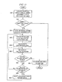
- FIGURE 6 is a flowchart detailing example operation of a particular embodiment of mobile drive unit 20 in moving to a designated destination according to the techniques illustrated by FIGURE 5 .
- FIGURE 5 illustrates an example showing routing and reservation techniques that may be utilized in particular embodiments of inventory system 10.
- FIGURE 5 illustrates an example in which mobile drive unit 20 receives an assigned task 18 from management module 15 that instructs mobile drive unit 20 to retrieve inventory holder 30a from a storage cell where inventory holder 30a is currently located. Mobile drive unit 20 then requests a path to the location of inventory holder 30a and follows the received path to the relevant location.
- workspace 70 is associated with a grid 12 comprising a plurality of cells 14, and mobile drive units 20 are configured to move within workspace 70 by navigating from the center of one cell 14 to the center of another.
- mobile drive units 20 may be configured to navigate grid 12 in any appropriate manner and starting points, destinations, and any intermediate points on the path traversed by mobile drive unit 20 may or may not represent the center point of a cell 14 or any other portion of grid 12.
- FIGURE 5 illustrates a grid-based embodiment of inventory system 10
- alternative embodiments of inventory system 10 may utilize a gridless workspace having an arbitrary shape and structure.
- the routing process begins with management module 15 transmitting a task assignment 18 to mobile drive unit 20.
- Task assignment 18 identifies one or more destinations associated with a corresponding task.
- Task assignment 18 may identify the relevant destinations directly or by reference to the known location of specific components (e.g., a particular inventory holder 30 or inventory station 50) or a particular portion of workspace 70.
- Task assignment 18 may also include any additional information suitable for mobile drive unit 20 to use in completing the assigned task.
- mobile drive unit 20 Upon receiving task assignment 18, mobile drive unit 20 requests a path to the location identified by the task assignment 18 or, if task assignment 18 identifies multiple locations, to the first location identified by task assignment 18.
- mobile drive unit 20 requests a path by transmitting a route request 22 to route planning module 94.
- route request 22 may include one or more destination locations and the current location of mobile drive unit 20 or the anticipated location of mobile drive unit 20 when it completes its current segment 17.
- management module 15 may independently monitor the location or assigned task of each mobile drive unit 20 and, consequently, one or more of these locations may be omitted from route request 22.
- route planning module 94 When route planning module 94 receives route request 22, route planning module 94 generates a path 16 for the requesting mobile drive unit 20 to use in moving from its current location to the requested destination. As noted above, route planning module 94 may use any suitable techniques to generate, select, or determine an appropriate path 16 for the requesting mobile drive unit 20. Route planning module 94 may then communicate information identifying path 16 to the requesting mobile drive unit 20 as part of a route response 24.
- route planning module 94 may communicate information specifying certain points along path 16, specifying directions and distances to move, specifying known path segments to use in moving to the requested destination, specifying other equipment (for example, a lift, conveyor, or truck) or features of the workspace (such as a ramp or tunnel) to be utilized, and/or indicating, in any other appropriate manner, the portion of workspace 70 mobile drive unit 20 should traverse in moving between its current location and the requested destination.
- route planning module 94 communicates path 16 to mobile drive unit 20 as part of route response 24.
- route planning module 94 transmits information identifying one or more paths 16, this information is received by mobile drive unit 20.
- mobile drive unit 20 may then store this information for subsequent use in navigating to the destination location.
- Mobile drive unit 20 attempts to reserve a segment 17 or other suitable portion of path 16.
- Mobile drive unit 20 may reserve a segment 17 of path 16 by taking any appropriate steps, based on the configuration of inventory system 10, to ensure that no other mobile drive unit 20, or other type of device capable of moving within workspace 70, is or will be traversing the reserved segment 17, positioned on the reserved segment 17, and/or otherwise impeding movement along the reserved segment 17 while the relevant mobile drive unit 20 has that segment 17 reserved.
- route planning module 94 may, in response to a particular route request 22, generate multiple paths to a particular destination. Moreover, management module 15 may then transmit all of the generated paths 16 to the requesting mobile drive unit 20. Additionally, route planning module 94 or mobile drive unit 20 may assign a priority to each of the generated paths 16. As a result, in such embodiments, the requesting mobile drive unit 20 may be capable of storing the multiple paths 16 generated by route planning module 94 and then attempting to reserve segments 17 of the highest priority path 16. If the attempted reservation is denied, the requesting mobile drive unit 20 may then attempt to request a segment 17 from the next highest priority path 16. The requesting mobile drive unit 20 may then proceed to request segments 17 from each of the received paths 16 in order of priority until the requesting mobile drive unit 20 successfully reserves segments 17 from one of the received paths 16.
- multiple mobile drive units 20 may be allowed to utilize a particular segment 17 simultaneously.
- mobile drive unit 20 may reserve a segment 17 by taking any appropriate steps to ensure that only mobile drive units 20 that satisfy particular conditions may use the reserved segment at the same time.
- segment reservation module 96 may reserve a particular segment by taking appropriate steps to ensure that only mobile drive units 20 moving in the same direction as that mobile drive unit 20 may reserve the relevant segment 17.
- inventory system 10 may be configured to allow a predetermined maximum number or concentration of mobile drive units 20 to use a given segment 17 and mobile drive unit 20 may reserve a given segment 17 by requesting a reservation for that segment 17. Management module 15 may then conditionally grant the reservation based on whether the current number or density of mobile drive units 20 utilizing the requested segment 17 is less than the predetermined maximum.
- mobile drive unit 20 reserves segment 17 by transmitting a reservation request 26 to segment reservation module 96.
- Reservation request 26 identifies the segment 17 that mobile drive unit 20 is attempting to reserve.
- Reservation request 26 may identify the relevant segment 17 in any manner appropriate based on the configuration and capabilities of mobile drive unit 20 and segment reservation module 96. For example, in particular embodiments, reservation request 26 identifies the relevant segment 17 by identifying the starting and ending coordinates of that segment 17, by specifying a direction and distance from the current location of mobile drive unit 20, or by including any other suitable information from which the requested segment 17 can be identified, either independently or based on other information maintained by segment reservation module 96 during operation.
- Segment reservation module 96 receives the reservation request 26 and extracts information identifying the requested segment 17 from reservation request 26. Segment reservation module 96 then determines whether or not the requesting mobile drive unit 20 can reserve the requested segment 17. In particular embodiments, segment reservation module 96 determines based solely on whether another mobile drive unit 20 currently has the requested segment 17 reserved. In alternative embodiments, however, segment reservation module 96 may determine based both on whether another mobile drive unit 20 currently has the requested segment 17 reserved and on a priority level associated with the requesting mobile drive unit 20 or a task the mobile drive unit 20 is currently completing whether the requesting mobile drive unit 20 can reserve the requested segment 17.
- segment reservation module 96 may refuse use of certain segments 17 (or segments 17 exceeding a certain size) to mobile drive units 20 having an insufficient priority level. In general, however, segment reservation module 96 may use any appropriate considerations to determine whether the received reservation request 26 can be satisfied.
- segment reservation module 96 may be configured to compensate for potential uncertainties in the location of mobile drive unit 20.
- segment reservation module 96 may attempt to reserve a modified segment that includes, but is larger than, the requested segment 17.
- Segment reservation module 96 may be configured to always modify reservation requests 26 in this manner, to modify reservation requests 26 when management module 15 determines the actual location of the requesting mobile drive unit 20 differs from the calculated location, or to modify reservation requests 26 at any other appropriate times.
- mobile drive units 20 may attempt to make and/or resource scheduling module 92 may grant reservations of different types depending on the manner in which requesting mobile drive units 20 intend to use the requested segment 17. Moreover, resource scheduling module 92 may follow different policies for granting or denying each of these different types of reservations.
- mobile drive units 20 may be configured to request a segment 17 that includes one or more cells 14 adjacent to the cells 14 through which path 16 runs. Consequently, when a requesting mobile drive unit 20 plans to rotate inventory holder 30 as part of its movement in completing a particular segment 16, the requesting mobile drive unit 20 may attempt to place rotation reservations on the cells 14 adjacent to the cell 14 in which mobile drive unit 20 intends to perform the rotation.
- segment reservation module 96 may allow other mobile drive units 20 to also place reservation requests on a particular neighboring cell 14 at the same time the first requesting mobile drive unit 20 has reserved that particular cell 14.
- resource scheduling module 92 may allow other mobile drive units 20 to reserve the neighboring cell 14 for purposes of encroaching into that cell 14 while rotating inventory holders 30 in other cells 14 that border the neighboring cell 14. This may reduce the number of delays mobile drive units 20 face when attempting to reserve a sufficiently large portion of workspace 70 to rotate inventory holders 30.
- segment reservation module 96 may notify the requesting mobile drive unit 20 that it did not successfully reserve the requested segment 17. For example, in the illustrated embodiment, segment reservation module 96 transmits a reservation response 28 that indicates the reservation was unsuccessful. Alternatively, in particular embodiments, segment reservation module 96 does not notify the requesting mobile drive unit 20 of the failed reservation, and the requesting mobile drive unit 20 is configured to determine the reservation was unsuccessful if the requesting mobile drive unit 20 does not receive an affirmative response within a predetermined period of time.
- segment reservation module 96 may be configured to take some remedial action if segment reservation module 96 is unable to satisfy a particular reservation request 26. For example, in particular embodiments, segment reservation module 96 may queue unsatisfied reservation requests 26 and attempt to satisfy them once any currently pending reservation for the requested segment 17 is terminated. Alternatively, however, segment reservation module 96 may be configured to discard unsatisfied reservation requests 26 after a single attempt to satisfy them, after a predetermined number of failed attempts, or after unsuccessfully attempting to satisfy such requests for a predetermined amount of time. The requesting mobile drive unit 20 may then be expected to transmit another reservation request 26 later if it is still attempting to reserve the requested segment 17.
- segment reservation module 96 may be configured to attempt reserving a portion of the requested segment 17 or a modified version of the requested segment 17 if the segment reservation module 96 is unable to successfully reserve the originally requested segment 17 for the requesting mobile drive unit 20. More generally, however, depending on the configuration of inventory system 10, segment reservation module 96 may be configured to take any appropriate remedial action or, alternatively, to take no remedial action at all, if segment reservation module 96 is unable to satisfy a particular reservation request 26.
- mobile drive unit 20 may execute any appropriate remedial action in response to determining that segment reservation module 96 has not satisfied the reservation.
- mobile drive unit 20 may wait a predetermined amount of time and attempt to reserve the same segment 17 again.
- mobile drive unit 20 may be configured to request a new path 16 from route planning module 94, if mobile drive unit 20 is unsuccessful in reserving the requested segment 17 or if mobile drive unit 20 is unsuccessful after a predetermined number of attempts.
- mobile drive units 20 may be able to adjust the size of the segments 17 mobile drive units 20 request.
- the requesting mobile drive unit 20 may, in response to determining that the attempted reservation was unsuccessful, attempt to reserve a smaller portion of the same requested segment 17. In such embodiments, the requesting mobile drive unit 20 may then request or automatically receive incremental portions of the original requested segment 17 as the requesting mobile drive unit 20 moves and/or the remaining portions become free. More generally, however, mobile drive unit 20 may respond in any suitable manner to the failed reservation attempt.
- segment reservation module 96 reserves the requested segment 17 for the requesting mobile drive unit 20. As part of reserving the requested segment, segment reservation module 96 stores information indicating the reserved state of the relevant segment 17 and takes any additional steps appropriate to ensure that the requesting mobile drive unit 20 may use the requested segment 17 until the reservation is terminated. Segment reservation module 96 also notifies the requesting mobile drive unit 20 that it has successfully reserved the requested segment 17. For example, in the illustrated embodiment, segment reservation module 96 transmits an acknowledgement, such as reservation response 28, that indicates to the requesting mobile drive unit 20 that the reservation was successful. When the requesting mobile drive unit 20 receives the reservation response 28 indicating that the attempted reservation was successful, the requesting mobile drive unit 20 begins moving along the reserved segment 17.
- mobile drive unit 20a when mobile drive unit 20a receives reservation response 28 indicating that mobile drive unit 20a has successfully reserved segment 17a, mobile drive unit 20 begins moving along segment 17a. This is illustrated is in FIGURE 5 by the dotted-line silhouette of mobile drive unit 20. At some point after beginning movement along segment 17a, mobile drive unit 20a attempts to reserve the next segment of the path that mobile drive unit 20a received from route planning module 94, i.e., segment 17b. In particular embodiments, mobile drive unit 20a may wait until mobile drive unit 20a reaches the end of the reserved segment (i.e., when mobile drive unit 20a reaches the second silhouette) and then request the next segment 17.
- mobile drive unit 20a may attempt to reserve segment 17b before completing segment 17a.
- mobile drive unit 20a may request segment 17b at an appropriate point while moving across segment 17a.
- mobile drive unit 20a may request segment 17b after completing a predetermined proportion of segment 17a (e.g., after completing 75% of segment 17a).
- mobile drive unit 20 may request segment 17b when only a predetermined amount of segment 17a is left to be completed (e.g., once mobile drive unit 20a has completed all but half a cell's width of segment 17a).
- mobile drive unit 20 may be configured to reserve the next segment in the current path at any suitable time while mobile drive unit 20 is moving along its currently-reserved segment 17.
- mobile drive unit 20 is configured to attempt reservation of a new segment 17 before completing its current segment 17.
- mobile drive unit 20a may include one or more sensors capable of detecting certain types of obstacles, obstructions, or other impediments to the movement of mobile drive unit 20.
- mobile drive unit 20 may be configured to stop and/or take any appropriate measures to complete the assigned task.
- mobile drive unit 20 may stop moving and periodically poll the relevant sensor to determine whether the obstacle has been removed.
- mobile drive unit 20a may request a new path upon detecting an obstacle located on or near a segment 17 of its current path 16.
- mobile drive unit 20 may notify management module 15 or a human operator of inventory system 10 to initiate appropriate actions to have the obstacle removed.
- mobile drive unit 20a may be configured to override its obstacle detection capabilities to support certain types of special navigation techniques. An example of these techniques is discussed in greater detail below with respect to FIGURES 12A-12E , 13 , and 14 .
- mobile drive unit 20a may release its reservation with respect to that cell 14.
- mobile drive unit 20a may wait until reaching the end of segment 17a (i.e., when mobile drive unit 20a arrives at the second silhouette), and then terminate its reservation of all cells 14 in segment 17a.
- Mobile drive unit 20a may release its reservation of all or a portion of segment 17a by transmitting a reservation termination message (not shown) to segment reservation module 96 or by taking any other appropriate steps to relinquish its use of segment 17a.
- mobile drive unit 20a may not be configured to take any affirmative steps to terminate the reservation.
- segment reservation module 96 may itself detect that mobile drive unit 20a has completed segment 17a and terminate the reservation in response or segment reservation module 96 may time-out the reservation if mobile drive unit 20a does not renew the reservation within a predetermined time period. More generally, segment reservation module 96 may monitor any particular aspect of the operation of mobile drive unit 20a including, for example, its location, speed, last renewal request, and/or any other appropriate aspect of the state of mobile drive unit 20a, and terminate the reservation at any appropriate time based on the state of mobile drive unit 20a.
- mobile drive unit 20a may begin moving along segment 17b. If mobile drive unit 20a has not successfully reserved segment 17b by the time mobile drive unit 20a reaches the end of segment 17a, mobile drive unit 20a may stop at the intersection of segment 17a and segment 17b and take appropriate steps based on the configuration of mobile drive unit 20a. For example, as noted above, mobile drive unit 20a may repeatedly attempt to reserve segment 17b until successful, make a predetermined number of reservation attempts and then request a new path 16, or take any other steps to continue its movement towards the destination location.
- mobile drive unit 20a Once mobile drive unit 20a successfully reserves segment 17b, mobile drive unit 20a traverses segment 17b in a similar fashion. At an appropriate point during the completion of segment 17b, mobile drive unit 20a attempts to reserve segment 17c and repeats the above process. Mobile drive unit 20a continues reserving and traversing segments (as suggested by the dotted-line silhouettes) until mobile drive unit 20a reaches the destination location. Mobile drive unit 20a may then take any actions appropriate to complete the assigned task. For example, in FIGURE 5 , completion of the assigned task may include mobile drive unit 20a docking with a particular inventory holder 30 located at the destination location.
- mobile drive unit 20a may request a path 16 to the next step by transmitting a new route request 22 to route planning module 94 and repeating the above process with respect to the next destination. If the task assignment 18 that mobile drive unit 20a received does not specify any additional locations, mobile drive unit 20a may request or be given another assigned task from resource scheduling module 92 or otherwise notify management module 15 that mobile drive unit 20a is available for new assignments.
- particular embodiments of inventory system 10 may be configured to generate paths that include segments covering turns, curves, and other non-linear portions. Additionally, although in the illustrated example segments 17 extend without limit between turns in path 16, particular embodiments of inventory system 10 may be configured to generate paths 16 that have an upper limit on segment length or to allow only up to a maximum segment length to be reserved with a single reservation. As a result, a relatively long straight segment, such as segment 17c, may in reality represent a series of smaller, connected segments 17 running in the same direction.
- mobile drive units 20 may, in particular embodiments, be configured to request new paths 16 to a particular location while in the process of completing a previously-requested path 16 to the same location.
- mobile drive units 20 may be configured to request a new path 16 if they are unsuccessful in reserving a particular segment 17 in the current path 16. More generally, however, mobile drive units 20 may be configured to request a new path 16 to a particular destination at any appropriate time while completing an existing path 16 to the same destination.
- a particular embodiment of mobile drive unit 20 may request a new path 16 a predetermined amount of time after requesting the original path, after completing each segment 17, or at any other suitable time.
- mobile drive unit 20 may transmit the originally received path 16 back to route planning module 94 to be used as a starting point for determining any improved paths 16 to the same-destination.
- management module 15 may be capable of pushing new paths 16 to a mobile drive unit 20 while that mobile drive unit 20 is in the process of completing a previously-received path 16.
- management module 15 may be configured to manage congestion by transmitting new paths 16 to mobile drive units 20 that are located in or near congested areas or that are traveling on paths that will traverse or pass near congested areas.
- management module 15 may be configured to improve the operational efficiency of inventory system 10 by transmitting new paths 16 to mobile drive units 20 that are optimized based on the attributes of inventory holders 30 or inventory stations 50 associated with the relevant mobile drive units 20 or the tasks they are completing.
- either mobile drive unit 20 or route planning module 94 may determine that mobile drive unit 20 should receive a new path 16 based on changes in any appropriate condition, circumstance, property, or state of inventory system 10 or any individual components of inventory system 10.
- route planning module 94 may be configured to transmit path 16 in portions.
- route planning module 94 may be configured to transmit path 16 to the requesting mobile drive unit 20 one segment 17 at a time. After traversing a particular segment 17, the requesting mobile drive unit 20 may then request another segment 17 of the path 16.
- route planning module 94 may determine, based on changes in conditions within workspace 70 and/or any other appropriate considerations, whether to provide the next segment 17 in the original path 16 or to generate a new path 16 to the destination of the requesting mobile drive unit 20.
- Route planning module 94 then communicates another segment 17, either from the original path 16 or a new path 16, to the requesting mobile drive unit 20. This process may continue until the requesting mobile drive unit 20 reaches its destination.
- management module 15 may be responsible for initiating reservations, either explicitly or implicitly.
- management module 15 may monitor the location and current path of mobile drive units 20 and may reserve appropriate segments 17 on behalf of mobile drive units 20 at appropriate times during the movement of mobile drive units 20.
- particular embodiments of inventory system 10 may include signaling devices, such as traffic signals, that mange the flow of traffic within workspace 70.
- management module 15 or other components that control the signaling devices may implicitly reserve a particular segment 17 for a mobile drive unit 20 by signaling to other mobile drive units 20 that they are not permitted to use the relevant segment 17 at a particular time.
- inventory system 10 supports a number of techniques that provide for efficient routing, navigation, and management of mobile drive units 20 moving within workspace 70. Because inventory system 10 supports techniques for resolving conflicting requests for a particular segment 17 by two different mobile drive units 20 management module 15 may also help reduce or eliminate collisions between mobile drive units 20 simultaneously completing tasks. As a result, the described techniques may provide one or more operational benefits.
- FIGURE 6 is a flow chart illustrating the operation of a particular embodiment of mobile drive unit 20 in traversing a path 16 to a designated location. More specifically, FIGURE 6 illustrates the process by which mobile drive unit 20, in particular embodiments of inventory system 10, requests a path to a particular destination and iteratively reserves and traverses the various segments 17 of that path 16. Any of the steps illustrated in FIGURE 6 may be combined, modified, or deleted where appropriate, and additional steps may also be added to those shown in the flowchart. Moreover, the described steps may be performed in any suitable order without departing from the scope of the invention.
- the example operation begins, at step 602, with mobile drive unit 20 receiving a task assignment 18 from resource scheduling module 92.
- Task assignment 18 identifies one or more locations associated with a task assigned to mobile drive unit 20.
- mobile drive unit 20 requests, from route planning module 94, a path to one of the destinations identified in task assignment 18.
- mobile drive unit 20 requests the path by transmitting a route request 22 to route planning module 94 at step 604.
- Route request 22 identifies a destination location and the current location of mobile drive unit 20.
- route planning module 94 generates, selects, or identifies a path 16 from the current location of mobile drive unit 20 to the destination location. Route planning module 94 then transmits path 16 to mobile drive unit 20.
- route planning module 94 transmits path 16 to mobile drive unit 20 by transmitting a route response 24 to mobile drive unit 20, at step 608, that identifies path 16 in an appropriate manner based on the capabilities of mobile drive unit 20.
- path 16 includes multiple segments 17, including at least an initial segment 17 and one or more additional segments 17. The initial segment 17 is associated with a section of workspace 70 adjacent to the current location of mobile drive unit 20 when mobile drive unit 20 requests the path, and at least one of the additional segments 17 is associated with a section of workspace 70 adjacent to the destination. Path 16 may include any number of additional segments 17.
- mobile drive unit 20 After receiving the path from route planning module 94, mobile drive unit 20 attempts to reserve the initial segment 17 of the received path 16. In particular embodiments, mobile drive unit 20 attempts to reserve the initial segment 17 by transmitting a reservation request 26 to segment reservation module 96 at step 610. Reservation request 26 identifies the requested segment 17.
- segment reservation module 96 Upon receiving reservation request 26, segment reservation module 96 attempts to reserve the requested segment 17 for mobile drive unit 20 at 612. In particular embodiments, segment reservation module 96 may modify the requested segment 17 to account for potential uncertainties or errors in the calculated position of mobile drive unit 20. As a result, in particular embodiments, segment reservation module 96 may reserve a portion of workspace 70 other than the segment specified by the received reservation request 26. For example, segment reservation module 96 may, under appropriate circumstances, expand, translate, and/or otherwise modify the requested segment to create a modified segment more suitable for use by the requesting mobile drive unit 20. In particular embodiments, segment reservation module 96 may be configured to modify the requested segment based on an error margin utilized by inventory system 10.
- Segment reservation module 96 may, as a result, attempt to reserve a portion of workspace 70 that is expanded, shifted, or otherwise modified from the reserved segment 17 in an amount determined based on the error margin.
- segment reservation module 96 may attempt to reserve a segment 17 that includes one or more cells 14, beyond that included in the requested segment 17, that extend in the direction that the requesting mobile drive unit 20 is currently traveling.
- segment reservation module 96 may attempt to reserve a segment that has been shifted a particular number of cells in a specified direction.
- Segment reservation module 96 may then notify mobile drive unit 20 of whether or not mobile drive unit 20 has successfully reserved a segment 17 for mobile drive unit 20. Alternatively, segment reservation module 96 may notify mobile drive unit 20 only of successful reservation attempts. In particular embodiments, segment reservation module 96 notifies mobile drive unit 20 by transmitting a reservation response 28 to mobile drive unit 20 at step 614.
- mobile drive unit 20 determines whether mobile drive unit 20 has successfully reserved the initial segment 17. If mobile drive unit 20 was not successful in reserving the initial segment 17, mobile drive unit 20 may take appropriate steps to continue working toward completion of the assigned task. For example, in the illustrated embodiment, mobile drive unit 20 waits a predetermined amount of time and attempts to reserve the initial segment again at step 618. Moreover, in the illustrated embodiment, mobile drive unit 20 determines at step 620 if the second attempt is successful. If the second attempt is successful, operation continues at step 622. If the second attempt is not successful, operation returns to 604 with mobile drive unit 20 requesting a new path 16.
- mobile drive unit 20 begins moving away from its original location along the initial segment of the path at step 622.
- mobile drive unit 20 determines that there is less than a predetermined portion of the initial segment 17 left to complete. As a result, mobile drive unit 20 determines, at step 626, whether any additional segments 17 remain to be completed in the current path 16.
- mobile drive unit 20 attempts to reserve the next segment 17, returning to step 610. If mobile drive unit 20 successfully reserves the next segment operation continues with mobile drive unit 20 moving along the next segment 17. If mobile drive unit is not successful in reserving the next segment 17, operation continues through to step 622. If mobile drive unit 20 reaches the end of the initial segment 17 before successfully reserving the next segment, mobile drive unit 20 may pause its movement at the end of the initial segment and remain stationary until mobile drive unit 20 successfully reserves the next segment or obtains an alternative path.
- mobile drive unit 20 determines whether any destinations remain to be visited in the current task assignment 18 at step 628. If so, operation returns to step 604. If not, mobile drive unit 20 may notify resource scheduling module 92 that mobile drive unit 20 has completed its current task at step 630. Operation with respect to completing the current task may then end as shown in FIGURE 6 .
- FIGURES 7 and 8 illustrate a technique for planning paths based on the current state of a requesting mobile drive unit 20. More specifically, FIGURE 7 illustrates an example of how such techniques might be implemented in a particular inventory system 10, and FIGURE 8 is a flowchart detailing example operation of management module 15 in implementing a particular embodiment of these techniques.
- particular embodiments of inventory system 10 may allow mobile drive units 20 that are not docked to an inventory holder 30 to move through spaces currently occupied by stored inventory holders 30, but mobile drive units 20 that are docked with inventory holders 30 may not be capable of doing so. As a result, when undocked, mobile drive units 20 may be able to "tunnel" through cells 14 having inventory holders 30, thereby allowing for more effective use of system resources.
- FIGURE 7 illustrates techniques that may be used by management module 15 in generating appropriate paths 16 for mobile drive units 20. More specifically, in particular embodiments, when mobile drive unit 20 requests a path 16, route planning module 94, management module 15 in general, or other appropriate components of inventory system 10 determine a state of the requesting mobile drive unit 20. As used in this description and the claims that follow, "state” may refer to transitional, temporary conditions, such as a current task assignment, that are associated with the requesting mobile drive unit 20 as well as permanent characteristics and properties, such as height and width, associated with the requesting mobile drive unit 20.
- Route planning module 94 then generates, selects, or identifies a path based in part on the state of the requesting mobile drive unit 20. More specifically, the state of mobile drive unit 20 may dictate the cells through which mobile drive unit 20 can travel, and route planning module 94 may produce a path 16 that utilizes appropriate cells 14.
- FIGURE 7 shows an example of two alternative paths 16, paths 16a and 16b, that might be generated by route planning module 94 based on a particular aspect of the state of the requesting mobile drive unit 20b. Specifically, FIGURE 7 illustrates two paths 16 that may be generated based on whether or not mobile drive unit 20b is currently docked with an inventory holder 30.
- mobile drive unit 20b receives a task assignment 18 as discussed above with respect to FIGURE 5 .
- Task assignment 18 identifies a destination associated with a corresponding task assigned to mobile drive unit 20b.
- mobile drive unit 20b requests path 16 from route planning module 94.
- mobile drive unit 20b requests path 16 by transmitting route request 22, which identifies the relevant destination location, here cell 14b.
- route planning module 94 In response to route request 22, route planning module 94 generates a path 16 to the destination location by identifying, selecting and/or otherwise generating an appropriate path 16. In generating path 16, route planning module 94 considers a particular aspect of the state of mobile drive unit 20b, here its docking status. Based on the relevant aspect of the requesting mobile drive unit's state, route planning module 94 may determine that the requesting mobile drive unit 20b is prohibited from moving through particular cells 14, from traversing particular paths 16, and/or from utilizing particular equipment (e.g., a drive lift) within workspace 70, and/or that the state of mobile drive unit 20b places some other form of restriction on the path 16 that route planning module 94 can properly generate for mobile drive unit 20b.
- particular equipment e.g., a drive lift
- the requesting mobile drive unit 20 may itself indicate the relevant state information to route planning module 94.
- mobile drive unit 20b may indicate its docking status in route request 22.
- route planning module 94 may monitor one or more mobile drive units 20 operating in workspace 70 and may maintain the relevant state information as part of its normal operation. Additionally, in particular embodiments, route planning module 94 may instead retrieve the relevant state information from other components of inventory system 10 when a particular mobile drive unit 20 requests a path 16. For example, in particular embodiments, when route planning module 94 receives a route request 22 from a particular mobile drive unit 20, route planning module 94 may communicate with resource scheduling module 92 to determine whether the requesting mobile drive unit 20 is currently assigned a task.
- route planning module 94 may generate a path for mobile drive unit 20 that circumvents all designated storage cells, such as the path shown in FIGURE 7 as path 16a.
- route planning module 94 may generate a path that includes designated storage cells 64, such as the path shown in FIGURE 7 as path 16b.
- route planning module 94 communicates path 16 to the requesting mobile drive unit 20.
- route planning module 94 transmits a route response 24 to the mobile drive unit 20b that identifies path 16.
- Mobile drive unit 20b then completes the received path 16 as discussed above.
- route planning module 94 may make more intelligent decisions regarding paths 16 that route planning module 94 generates for that mobile drive unit 20.
- route planning module 94 may consider the state of a requesting mobile drive unit 20 to allow route planning module 94 to selectively use cells, paths, or equipment that might be prohibited for use by mobile drive units 20 of a certain state.
- route planning module 94 may consider the state of a requesting mobile drive unit 20 to limit the use of particular cells, paths, or equipment by mobile drive units 20 of a particular state so that they can be available for use by mobile drive units 20 having states preferable for using the relevant cell, path, or equipment.
- route planning module 94 may, as already discussed, consider the docking status of the requesting mobile drive unit 20 when generating the path. Similarly, in particular embodiments (for example, embodiments in which mobile drive units 20 do not actually dock with inventory holders 30 they transport), route planning module 94 may alternatively consider whether the requesting mobile drive unit 20 is carrying a load when generating the path. As a result, route planning module 94 may be able to selectively use a cell 14 that might otherwise be prohibited for use in routing because docked or loaded mobile drive units 20 cannot traverse the cell 14 in question due to the presence of a stored inventory holder 30, the position of overhanging stairs, or other physical limitations that prevent a docked or loaded mobile drive unit 20 from being able to cross cell 14. Consequently, cells 14 that would otherwise have to be prohibited from use in any paths may be selectively utilized in paths for appropriate mobile drive units 20, thereby increasing the space resources available to route planning module 94 for routing requested paths 16.
- route planning module 94 may use the docking or loading status of the requesting mobile drive unit 20 as a proxy for determining the urgency of the path 16 that mobile drive unit 20 is requesting. As a result, in particular embodiments, route planning module 94 may decide not to route undocked or unloaded mobile drive units 20 through cells in high-traffic areas even if the resulting path 16 is significantly longer. Similarly, in particular embodiments, route planning module 94 may decide not to generate paths for undocked or unloaded mobile drive units 20 that require the use of scarce equipment resources, such as drive lifts, to complete the paths. Consequently, route planning module 94 may generate prioritized routes for certain mobile drive units 20 based on the docking or loading status of those mobile drive units 20.
- route planning module 94 may consider the power or fuel level of the requesting mobile drive unit 20 when generating path 16. As a result, route planning module 94 may, based on the charge or fuel level of the requesting mobile drive unit 20, generate a path 16 that is less than some maximum length to ensure the requesting mobile drive unit 20 does not end up stranded, even if this path will increase the probability that the requesting mobile drive unit 20 will be delayed by congestion. Similarly, route planning module 94 may decide based on the fuel or charge level of the requesting mobile drive unit 20 to generate a path that runs near a recharging or refueling station to allow the requesting mobile drive unit 20 to recharge or refuel while en route to the destination location,
- route planning module 94 may also consider the current assignment state of a requesting mobile drive unit 20 in generating path 16 for that mobile drive unit 20. This assignment state may relate to whether that mobile drive unit 20 is currently assigned a task, the priority of that task, and/or any other consideration relating to the tasks currently or previously assigned to that mobile drive unit 20. As a result, in particular embodiments, route planning module 94 may only route mobile drive units 20 that are currently assigned a high-priority task through what would otherwise be high-traffic cells 14.
- route planning module 94 may decide to generate a path that requires use of scare equipment resources, such as drive lifts, only if the requesting mobile drive unit 20 is currently assigned a task or, alternatively, a high-priority task. Consequently, in particular embodiments, route planning module 94 generates paths 16 that are quicker to complete for mobile drive units 20 currently assigned a task, or for those currently assigned a high-priority task.
- route planning module 94 may be configured to consider the physical characteristics of the requesting mobile drive unit 20 in generating path 16. As a result, in such an embodiment, the fact that it may be physically impossible for certain mobile drive units 20 to move through certain cells 14, follow certain paths 16, or use certain equipment, may not cause route planning module 94 to forgo use of such cells 14, paths 16, or equipment when generating paths for all mobile drive units 20.
- route planning module 94 may, in particular embodiments, consider any one or more aspects of the state of mobile drive unit 20, or of the load that mobile drive unit 20 is carrying, in generating a requested path 16. Consequently, route planning module 94 may, in particular embodiments, be able to further optimize the use of resource in inventory system 10 by tailoring path 16 to meet the requirements of the requesting mobile drive unit 20. Furthermore, by considering both the destination provided by mobile drive unit 20 and the state of the requesting mobile drive unit 20 in generating path 16, certain embodiments of route planning module 94 may be able to facilitate the completion of a second goal (such as recharging) with little or no impact on the ability of mobile drive unit 20 to complete its assigned task. As a result, particular embodiments of inventory system 10 that implement the techniques described with respect to FIGURE 7 may provide a number of operational benefits.
- FIGURE 8 is a flowchart illustrating operation of an example embodiment of route planning module 94 in implementing some or all of the techniques described with respect to FIGURE 7 . While FIGURE 8 focuses on a particular embodiment of inventory system 10 that considers a particular aspect of the state of a mobile drive unit 20 in generating a path 16 to a particular destination for that mobile drive unit 20, alternative embodiments of inventory system 10 may be configured to consider any appropriate aspect of the state of mobile drive units 20 when generating paths 16. Additionally, any of the steps illustrated in FIGURE 8 may be combined, modified, or deleted where appropriate, and additional steps may also be added to those shown in the flowchart. Moreover, the described steps may be performed in any suitable order without departing from the scope of the invention.
- Operation begins at step 640 with route planning module 94 receiving a route request 22 from a mobile drive unit 20.
- Route request 22 identifies a destination location within workspace 70.
- workspace 70 comprises at least one cell 14 associated with a first cell attribute and at least one cell that is not associated with the first cell attribute.
- those cells 14 which require tunneling to traverse are associated with a tunneling attribute, while those cells which do not require tunneling are not associated with the tunneling attribute.
- all storage cells 64 in workspace 70 are associated with the tunneling attribute, and therefore require an mobile drive unit 20 to be tunneling to traverse them.
- all cells 14 that are not storage cells 64 (“non-storage cells”) in workspace 70 are not associated with the tunneling attribute, and these non-storage cells 64 can be traversed without tunneling.
- route planning module 94 determines a state of the mobile drive unit 20. As discussed above, route planning module 94 may determine the state of mobile drive unit 20 based on information included in route request 22 or other communication with the requesting mobile drive unit 20, information maintained by route planning module 94, information received from another component of inventory system 10, and/or any other suitable information. In response to determining that the requesting mobile drive unit 20 is associated with a first state, route planning module 94 generates a path 16 to the destination location for mobile drive unit 20 that may traverse cells 14 that are associated with the first cell attribute at step 644. In this case, the generated path 16 may traverse both cells that are associated with the first cell attribute and cells that are not associated with the first cell attribute.
- route planning module 94 In response to determining mobile drive unit 20 is not associated with the first state, however, route planning module 94 generates a path 16 to the destination location for mobile drive unit 20 that does not traverse any cells 14 associated with the first cell attribute at step 646. In this case, the generated path 16 traverses only cells that are not associated with the first cell attribute. While, in particular embodiments, the generated path 16 may allow for a particular mobile drive unit 20 to enter and exit a cell associated with the first cell attribute from the same direction (e.g. to drop off an inventory holder 30 in an empty storage cell 64) the generated path 16, in such embodiments, will not allow or require the requesting mobile drive unit 20 to traverse any such cells 14.
- route planning module 94 may determine whether mobile drive unit 20 is currently in a docked or undocked state. If route planning module 94 determines at step 642 that the requesting mobile drive unit 20 is currently docked, route planning module 94 generates a path 16 between the first destination and the second destination that only includes cells 14 that are not designated as storage cells 64, such as path 16a in FIGURE 7 . Instead, if route planning module 94 determines that the requesting mobile drive unit 20 is not currently docked, route planning module 94 may generate a path 16 that includes cells 14 that are designated as storage cells 64 as well as cells 14 that are designated as non-storage cells, such as path 16b in FIGURE 7 .
- route planning module 94 communicates path 16 to the requesting mobile drive unit 20.
- route planning module 94 communicates the generated path 16 to the requesting mobile drive unit 20 by transmitting a route response 24 to the requesting mobile drive unit 20 that specifies the generated path 16 at step 648.
- Route response 24 includes information defining the generated path 16.
- mobile drive unit 20 may then begin traversing the generated path 16 to the destination location, and the operation of route planning module 94 with respect to generating this path 16 ends, as shown in FIGURE 8 .
- FIGURES 9-11 illustrate techniques for selecting a destination for mobile drive unit 20 based on the state of the relevant mobile drive unit 20. More specifically, FIGURE 9 illustrates an example of how management module 15 might utilize such techniques to select destinations for mobile drive units 20 based on their task assignments, while FIGURE 10 illustrates an example of how management module 15 might utilize such techniques to select a destination for mobile drive units 20 based on their capability to complete tasks. Additionally, FIGURE 11 is a flowchart illustrating example operation of management module 15 in a particular implementation of these techniques.
- mobile drive units 20 and inventory holders 30 may be sized and shaped to allow an undocked mobile drive unit 20 and an inventory holder 30 to share the same portion of workspace 70, such as storage cells 64.
- management module 15 may instruct mobile drive units 20 that are not currently engaged in completing any assigned tasks to park in a space currently storing an inventory holder 30. This may reduce the possibility of an idle mobile drive unit 20 becoming an obstacle in workspace 70 and free more room for traffic. Additionally, these techniques may result in idle mobile drive units 20 being directed to a location selected to best situate the relevant mobile drive unit 20 for responding to its next assignment.
- the example illustrated by FIGURE 9 begins with resource scheduling module 92 determining a state of mobile drive unit 20c.
- resource scheduling module 92 determines an assignment state of mobile drive unit 20c.
- the assignment state may relate to whether the relevant mobile drive unit 20 is currently assigned one or more tasks, is actively engaged in completing one or more tasks, has just completed one or more previously-assigned tasks, and/or any other consideration associated with the tasks that have been assigned to and/or completed by mobile drive unit 20c.
- resource scheduling module 92 may determine the assignment state of a particular mobile drive unit 20 in any appropriate manner.
- mobile drive units 20, upon completing a task notify resource scheduling module 92 of the fact that they have completed their currently assigned tasks.
- mobile drive unit 20c notifies resource scheduling module 92 by transmitting a task completion message 192.
- Task completion message 192 indicates to resource scheduling module that the mobile drive unit 20 that transmitted task completion message 192 has completed its currently-assigned task.
- Task completion message 192 may include an identifier for the idle mobile drive unit 20 and/or other information suitable to allow resource scheduling module 92 to determine that the relevant mobile drive unit 20 has completed its task.
- resource scheduling module 92 determines the assignment state of mobile drive unit 20c based on receipt of task completion message 192.
- resource scheduling module 92 may monitor one or more mobile drive units 20 operating in workspace 70 and may maintain the relevant state information as part of its normal operation.
- resource scheduling module 92 selects a destination for mobile drive unit 20c that is chosen based on the fact that mobile drive unit 20c is idle. Depending on the configuration of inventory system 10, resource scheduling module 92 may use the knowledge that mobile drive unit 20c is idle in any suitable manner in selecting an appropriate destination for mobile drive unit 20c. By providing special treatment for idle mobile drive units 20, resource scheduling module 92 may selectively place these mobile drive units 20 to improve the overall effectiveness of inventory system 10.
- resource scheduling module 92 may direct mobile drive unit 20c to low-traffic locations to prevent mobile drive unit 20c from creating congestion while it awaits another task.
- resource scheduling module 92 may select a destination location from among storage cells 64 that currently hold a stored inventory holder 30. Storage cells 64c, 64d, and 64e in FIGURE 9 illustrate examples of such locations.
- resource scheduling module 92 may direct mobile drive unit 20c to a low-traffic destination by selecting a cell 14 that is otherwise inaccessible by mobile drive units 20, as a destination and/or to move through, that are currently docked with an inventory holder 30.
- resource scheduling module 92 may identify a destination from among cells 14 in workspaces that have overhanging staircases, narrow entryways, low ceilings, and/or are otherwise inaccessible by mobile drive units 20 docked with the inventory holders 30 used in that embodiment of inventory system 10. This may help ensure that mobile drive units 20 transporting inventory holders 30 will not need to use the cell 14 selected as a parking space for mobile drive unit 20c.
- Workspace 70 illustrated in FIGURE 9 includes a stairway 890 that prevents mobile drive units 20 transporting inventory holders 30 from moving through at least cells 14c - 14g.
- cells 14c-14g illustrate an example of this type of inaccessible cell in FIGURE 9 .
- resource scheduling module 92 may direct mobile drive unit 20c to a low-traffic destination by selecting a destination location based on the actual traffic flow through the relevant area. For example, resource scheduling module 92 may consider the frequency with which a particular cell 14 is included in paths 16 generated by route planning module 94, the frequency with which segments that include that cell 14 are requested for reservation, and/or any other appropriate indicator of traffic flow, and may then select a destination for mobile drive unit 20c from among cells 14 that are only infrequently used by mobile drive units 20. Cells 14h-14j in FIGURE 9 are assumed, for the purposes of this example, to be infrequently used by mobile drive units 20 and thus illustrate an example of this type of location.
- resource scheduling module 92 may attempt to improve operation of inventory system 10 by placing mobile drive unit 20c in an optimal position for responding to subsequent tasks assigned to mobile drive unit 20c. For example, in particular embodiments, resource scheduling module 92 may select a destination location for mobile drive unit 20c that is close to stored inventory holders 30. Cells 14k-141 in FIGURE 9 illustrate generic examples of this type of location.
- resource scheduling module 92 may select a destination for mobile drive unit 20c that is close to frequently-requested inventory holders 30. For example, in a mail-order warehouse, resource scheduling module 92 may select a destination for mobile drive unit 20c near inventory holders 30 that store top-selling inventory items 40. As a result, in such embodiments, resource scheduling module 92 may consider the frequency with which particular inventory holders 30 are used in responding to inventory requests and select a location for mobile drive unit 20c that is near a frequently-requested inventory holder 30. Moreover, in particular embodiments, resource scheduling module 92 may attempt to achieve both goals by selecting a destination for mobile drive unit 20c that is located in a storage cell 64 that holds a frequently-requested inventory holder 30.
- mobile drive unit 20c may be kept out of traffic and also optimally positioned for responding to subsequent tasks likely to be assigned to mobile drive unit 20.
- inventory holders 30m and 30n are assumed to be frequently-requested inventory holders.
- storage cells 64m and 64n in FIGURE 9 represent example locations that satisfy both goals.
- resource scheduling module 92 may select any particular type of location as a destination for a mobile drive unit 20 having a particular assignment status. Additionally, while FIGURE 9 illustrates an example configuration in which particular types of cells 14 that may be selected as destinations are located in particular locations in workspace 70, resource scheduling module 92 may utilize destinations of any type located anywhere within workspace 70.
- resource scheduling module 92 After selecting a destination for mobile drive unit 20c, resource scheduling module 92 communicates the destination location to mobile drive unit 20c. In the illustrated embodiment, resource scheduling module 92 transmits a task assignment 18 that identifies the selected destination location. In particular embodiments, mobile drive unit 20c may then request a path and move to the destination, as described with respect to FIGURE 5 . In particular embodiments, mobile drive unit 20 may then wait at the destination until receiving another task assignment 18.
- resource scheduling module 92 may reduce the probability that such mobile drive units 20 will create congestion while they wait for further assignments. Furthermore, by placing idle mobile drive units 20 near inventory holders 30 or other appropriate components of inventory system 10, resource scheduling module 92 can reduce the completion time for future tasks that idle mobile drive units 20 are assigned. More generally, a particular embodiment of inventory system 10 may be configured to use the knowledge that a particular mobile drive unit 20 is idle in any appropriate manner to select a destination for that mobile drive unit 20. By strategically placing mobile drive units 20 when they are not being used, resource scheduling module 92 can further increase the overall efficiency and throughput of inventory system 10.
- FIGURE 10 illustrates another example of how resource scheduling module 92 may use various aspects of the state of a mobile drive unit 20 to determine a location for that mobile drive unit 20. More specifically, FIGURE 10 illustrates how resource scheduling module 92 may use a capability state of a mobile drive unit 20 to determine a location for that mobile drive unit 20. By determining an appropriate destination for a mobile drive unit 20 based on the repair status, energy supply status, and/or any other consideration relating to the ability of that mobile drive unit 20 to complete assigned tasks, in general, and/or to complete a particular assigned task, resource scheduling module 92 may optimize the placement of mobile drive units 20 in need of repair, re-supply, and/or other types of maintenance to regain or improve their capability of completing assigned tasks.
- resource scheduling module 92 determines the state or a particular aspect of the state of mobile drive unit 20d.
- resource scheduling module 92 determines a capability state of mobile drive unit 20d.
- the capability state may relate to the repair status, supply status, maintenance status, and/or any other aspect of the mobile drive units current ability or anticipated future ability to complete assigned tasks.
- Resource scheduling module 92 may determine the capability state of mobile drive unit 20d in any appropriate manner.
- mobile drive units 20d is configured to transmit a capability message 990 when its capabilities change and/or an event affecting its capabilities occurs.
- a mobile drive unit 20 may transmit a capability message 990 when its fuel level or battery charge level drops, parts or components of mobile drive unit 20d break or become unusable, a scheduled maintenance period for mobile drive unit 20d elapses, or any other event occurs affecting or potentially affecting the ability of mobile drive unit 20d to complete assigned tasks and/or remain active.
- resource scheduling module 92 may monitor various characteristics of mobile drive units 20 or events associated with mobile drive units 20 as part of its normal operation and determine the capability state of mobile drive units 20 based on the monitored information. In yet other embodiments, resource scheduling module 92 may receive information from other components of inventory system 10 from which resource scheduling module 92 determines the capability state of mobile drive units 20. In general, however, resource scheduling module 92 may determine the capability state of a particular mobile drive unit 20 using any appropriate information obtained from any suitable source.
- resource scheduling module 92 after determining the capability state of mobile drive unit 20d from capability message 990, selects a location for mobile drive unit 20d based on this capability state. Resource scheduling module 92 then generates a task assignment 18 identifying the selected location and transmits task assignment 18 to mobile drive unit 20 for completion. By selecting a destination appropriate for mobile drive unit 20 based on its capability state, resource scheduling module 92 may be able to reduce the effects of damage, energy depletion, and other debilitating occurrences on the congestion, throughput, and responsiveness of inventory system 10.
- the capability state of mobile drive unit 20d may relate to its state of repair. If any components, or a specific component, of mobile drive unit 20d breaks or becomes unusable, mobile drive unit 20 may transmit capability message 990 to resource scheduling module 92. Resource scheduling module 92 may then select a destination for mobile drive unit 20 based on the knowledge that mobile drive unit 20d needs repair.
- inventory system 10 may include automated repair stations 992 that are capable of repairing certain types of malfunctions or replacing certain types of parts.
- inventory system 10 may include an automated repair station 992 that can replace blown tires, clean sensors, or perform other types of repairs with limited or no human involvement.
- resource scheduling module 92 may select a destination at or near an appropriate automated repair station 992, such as cells 14m, 14n, and 14o, in response to determining mobile drive unit 20d needs repair or, in response to determining mobile drive unit 20d needs a particular type of repair.
- inventory system 10 may include cells 14, such as cells 14p and 14q that provide easy access for human operators attempting to repair mobile drive units 20, and resource scheduling module 92 may be configured to send mobile drive units 20 to these cells for at least certain types of repairs.
- some or all of workspace 70 may be enclosed by a wall, railing, or other barrier that prevents or limits entry to workspace 70 and resource scheduling module 92 may select a destination near access points to workspace 70 (such as doors 998 in FIGURE 10 ).
- resource scheduling module 92 may select a destination that is located away from high-traffic areas, reserved for repair work, or otherwise situated to allow human operators safe and/or easy access to mobile drive units needing repair.
- resource scheduling module 92 may select a destination, such as cells 14p and 14q, for mobile drive unit 20d that is easily accessible to human operators.
- the capability state of mobile drive unit 20d may relate to its fuel or charge level.
- mobile drive unit 20d may transmit capability message 990 indicating its fuel level, battery charge, or other appropriate form of energy level to resource scheduling module 92.
- Resource scheduling module 92 may then select an appropriate destination for mobile drive unit 20d based on this information.
- inventory system 10 may include one or more energy stations 996 at which mobile drive units 20 may be recharged or refueled, receive a new battery, or otherwise receive additional energy for responding to assigned tasks.
- resource scheduling module 92 may select a destination, such as cells 14r, 14s, or 14t, that is close to an appropriate energy station 996.
- resource scheduling module 92 may be configured to send mobile drive units 20 that need repair, refuel, or recharging to low-traffic cells 14. Consequently, in such embodiments, mobile drive units 20 that are not capable of completing assigned tasks will not impede traffic while awaiting repair or removal from inventory system 10. In doing so, resource scheduling module 92 may consider the frequency with which a particular cell 14 is included in paths 16 generated by route planning module 94, the frequency with which segments that include that cell 14 are requested for reservation, and/or any other appropriate indicator of traffic flow, and may then select a destination for mobile drive unit 20d from among cells 14 that are only infrequently used by mobile drive units 20.
- resource scheduling module 92 may consider the fact that, because of physical constraints, system policies, and/or any other suitable considerations a particular cell 14 is not otherwise available as a destination for mobile drive units 20 and/or for mobile drive units 20 to move through.
- cells 14u and 14v in are assumed, for the purposes of this example, to be infrequently used by mobile drive units 20 and thus illustrate an example of this type of location.
- resource scheduling module 92 may select a destination in a low-traffic area, such as cells 14u or 14v.
- resource scheduling module 92 may select a particular task or tasks for a mobile drive unit 20 based on the degraded capabilities of mobile drive unit 20.
- resource scheduling module 92 may assign that mobile drive unit 20 a task associated with lighter inventory holders 30, inventory holders 30 closer to the position of the mobile drive unit 20, or otherwise better suited for transport by the degraded mobile drive unit 20 than the inventory holders 30 associated with other tasks.
- resource scheduling module 92 may select for the relevant mobile drive unit 20 a destination location associated with such inventory holders 30.
- resource scheduling module 92 may select any particular type of location as a destination for a mobile drive unit 20 having a particular capability state. Additionally, while FIGURE 10 illustrates an example configuration in which particular types of cells 14 that may be selected as destinations are located in particular locations in workspace 70, resource scheduling module 92 may utilize destinations of any type located anywhere within workspace 70.
- resource scheduling module 92 After resource scheduling module 92 selects an appropriate destination for mobile drive unit 20d based on its capability state, resource scheduling module 92 communicates the destination to mobile drive unit 20d. In the illustrated example, communicates the destination by transmitting a task assignment 18 to mobile drive unit 20d that identifies the selected destination. Mobile drive unit 20d then requests a path 16 to the selected destination and travels the path to the selected destination as described above with respect to FIGURE 5 . In particular embodiments, mobile drive unit 20 may then remain at the selected destination until being repaired or receiving appropriate maintenance. Mobile drive unit 20 may then become available to receive other task assignments from resource scheduling module 92.
- resource scheduling module 92 may instead determine the capability state of a particular mobile drive unit 20 based on information resource scheduling module 92 retrieves from a source other than the relevant mobile drive unit 20.
- mobile drive unit 20 may be repaired or maintained according to a repair or maintenance schedule, and resource scheduling module 92 may determine the capability state of a particular mobile drive unit 20 based on this schedule and stored information indicating the last time the relevant mobile drive unit 20 was repaired or received maintenance.
- resource scheduling module 92 can limit the negative impact of mobile drive units 20 that are damaged, expended, or otherwise incapable of completing assigned tasks. Moreover, by choosing parking spaces in low-traffic areas for such mobile drive units 20, particular embodiments of resource scheduling module 92 may reduce the probability that such mobile drive units 20 will create congestion while they await repair or maintenance. More generally, a particular embodiment of inventory system 10 may be configured to use the knowledge that a particular mobile drive unit 20 is damaged, expended, or otherwise incapable of completing assigned tasks in any appropriate manner to select a destination for that mobile drive unit 20. By strategically locating mobile drive units 20 that are in such a state, resource scheduling module 92 can further increase the overall efficiency and throughput of inventory system 10.
- FIGURE 11 is a flowchart illustrating the operation of a particular embodiment of resource scheduling module 92 in selecting a destination location for a mobile drive unit 20. More specifically, FIGURE 11 illustrates the process by which resource scheduling module 92, in particular embodiments of inventory system 10, selects a destination for a particular mobile drive unit 20 based on the state of that mobile drive unit 20. Although FIGURE 11 focuses on an example in which resource scheduling module 92 selects a destination for mobile drive unit 20 based on an assignment state of the mobile drive unit 20, particular embodiments of resource scheduling module 92 may be configured to instead select a destination based on a capability state or any other aspect of the overall state of the relevant mobile drive unit 20. Additionally, any of the steps illustrated in FIGURE 11 may be combined, modified, or deleted where appropriate, and additional steps may also be added to those shown in the flowchart. Moreover, the described steps may be performed in any suitable order without departing from the scope of the invention.
- Operation begins with resource scheduling module 92 determining an assignment state of a particular mobile drive unit 20 at step 650.
- the assignment state may relate to whether the mobile drive unit 20 is currently assigned one or more tasks, is actively engaged in completing one or more tasks, and/or has just completed one or more previously-assigned tasks, and/or any other aspect of the tasks that have been assigned to and/or completed by mobile drive unit 20.
- resource scheduling module 92 determines, based on this assignment state, whether mobile drive unit 20 is currently completing any assigned tasks.
- resource scheduling module 92 may allow mobile drive unit 20 to complete its assigned task and operation of resource scheduling module 92 with respect to selecting a destination for that mobile drive unit 20 may end as shown in FIGURE 11 .
- resource scheduling module 92 determines that mobile drive unit 20 is not currently completing any assigned tasks, resource scheduling module 92 selects a destination for mobile drive unit 20, at step 654, based on the assignment state of mobile drive unit 20. Depending on the configuration of resource scheduling module 92, resource scheduling module 92 may select any appropriate destination for mobile drive unit 20 based on its assignment state. In particular embodiments, resource scheduling module 92 may select a low-traffic destination or a destination near locations associated with anticipated future tasks. Thus, in response to determining that mobile drive unit 20 is idle, resource scheduling module 92 may select a location based on a traffic level associated with the destination, based on its proximity to inventory holders 30, or based on any other consideration appropriate a state of the mobile drive unit 20.
- resource scheduling module 92 transmits information identifying the selected destination to mobile drive unit 20.
- resource scheduling module 92 transmits a task assignment 18 that includes the selected destination.
- mobile drive unit 20 moves to the selected destination.
- Mobile drive unit 20 then waits until it receives another assigned task at step 660. Thus, at step 662, mobile drive unit 20 determines whether mobile drive unit 20 has received another assigned task. If so, mobile drive unit 20 begins executing the assigned task at step 664, and the operation of resource scheduling module 92 with respect to selecting a destination for mobile drive unit 20 ends as shown in FIGURE 11 .
- resource scheduling module 92 may determine, at step 666, that a portion of workspace 70 associated with the selected destination, such as a cell 14 that contains the selected destination, is needed for another use. As a result, resource scheduling module 92 may select another destination for mobile drive unit 20 at step 668, and operation may return to step 656 with resource scheduling module 92 transmitting information identifying the newly-selected location to mobile drive unit 20.
- FIGURES 12A-12E , 13 , and 14 illustrate a technique for managing the coordinated movement, or "platooning," of mobile drive units 20. More specifically, FIGURES 12A-12E illustrate an example of how coordinated movement techniques might be implemented and utilized in a particular embodiment of inventory system 10.
- FIGURE 13 is a flowchart illustrating example operation of management module 15 in utilizing a particular implementation of these techniques
- FIGURE 14 is a flowchart illustrating example operation of a mobile drive unit 20 in utilizing a particular implementation of these techniques.
- management module 15 may employ modified reservation policies for a group of mobile drive units 20 that are moving in the same direction.
- one or more mobile drive units 20 in the rear of the group may be allowed to reserve a segment 17 that includes a particular cell 14 occupied by the mobile drive unit 20 in front of that mobile drive unit 20 before the front mobile drive unit 20 vacates the relevant cell 14, based on the expectation that the mobile drive unit(s) 20 in the front will be moving at the same time that the mobile drive unit(s) 20 in the back are moving and that, as a result, a collision will not occur despite the relaxed reservation policy.
- FIGURES 12A-12B illustrate an example of how these policies might be implemented in the case of mobile drive units 20 that are not moving in the same direction. More specifically, FIGURES 12A-12B show an example in which mobile drive unit 20e is attempting to reserve a path segment 17x to move in the direction indicated by arrow 401. In the illustrated example, segment 17x is presently reserved and occupied by mobile drive unit 20f. Moreover, mobile drive unit 20e is attempting to move towards mobile drive unit 20f as indicated by arrow 402. FIGURES 12A and 12B also show a drive identification signal 430 that is generated by mobile drive unit 20f and described in greater detail below with respect to FIGURES 12C-12E .
- FIGURE 12A shows the location of mobile drive units 20e and 20f, in this example, when mobile drive unit 20e attempts to reserve segment 17x.
- mobile drive unit 20e attempts to reserve segment 17x by transmitting reservation request 26 to management module 15. Similar to the result under the reservation policies described above with respect to FIGURE 5 , this reservation request 26 will be denied even under the modified reservation policies utilized in this example, because mobile drive unit 20f already occupies cell 14xx on the requested segment 17x and mobile drive unit 20e and mobile drive unit 20f are not moving in the same direction.
- management module 15 notifies mobile drive unit 20e that the attempted reservation was unsuccessful by transmitting reservation response 28 indicating that the reservation was unsuccessful, as shown in FIGURE 12B .
- mobile drive units 20e may be equipped with an obstacle sensor that senses objects in the path of mobile drive unit 20e, including other mobile drive units 20.
- mobile drive unit 20e may stop moving if mobile drive unit 20e detects mobile drive unit 20f in its path while in transit, or may refrain from requesting a reservation if mobile drive unit 20e detects mobile drive unit 20f on a segment 17, such as segment 17x, that mobile drive unit 20e is attempting to reserve. Consequently, in particular embodiments, mobile drive unit 20e may not even attempt to reserve segment 17x if mobile drive unit 20e detects mobile drive unit 20f on segment 17x as is shown in the example.
- FIGURES 12C-12E illustrate an example of how the modified policies might operate in the case of mobile drive units 20 that are moving in the same direction.
- mobile drive unit 20e is again attempting to reserve path segment 17x to move in the direction indicated by arrow 401.
- segment 17x is already reserved and occupied by mobile drive unit 20f.
- mobile drive unit 20f is attempting to move away from mobile drive unit 20e as indicated by arrow 403.
- FIGURE 12C shows the location of mobile drive units 20e and 20f when mobile drive unit 20e attempts to reserve segment 17x.
- mobile drive unit 20e again attempts to reserve segment 17x by transmitting a reservation request 26 to management module 15.
- segment reservation module 96 (or another appropriate component of management module 15) determines that mobile drive unit 20f is moving in the same direction as mobile drive unit 20e.
- segment reservation module 96 decides that it is acceptable to allow mobile drive unit 20e to reserve segment 17x sooner than mobile drive unit 20e would otherwise be able to do so.
- management module 15 may transmit a reservation response 28 indicating that mobile drive unit 20f has successfully reserved segment 17, as shown in FIGURE 12D .
- mobile drive unit 20e may be able to successfully request reservations that overlap with the reservations of mobile drive unit 20f based on the fact that mobile drive units 20e and 20f are moving in the same direction as one another. Additionally, depending on the specific policies implemented by the relevant embodiment of inventory system 10, mobile drive unit 20e may also be permitted to move into a given cell 14 earlier than would otherwise be allowed. As a result, in particular embodiments, mobile drive unit 20e may, at particular times during its movement along segment 17x, occupy a portion of the same cell 14 as mobile drive unit 20e, as shown in FIGURE 12E . Thus, the modified reservation policies shown in FIGURES 12C-12E allow for mobile drive units 20 traveling in the same direction to follow one another with a much smaller distance separating them than would otherwise be allowed.
- mobile drive unit 20e may also include a collision detector capable of detecting obstacles in its way. If the collision detector detects an obstacle in the path of mobile drive unit 20e, the collision detector may prevent mobile drive unit 20e from moving even if mobile drive unit 20e has successfully reserved the segments 17 in its path. Therefore, in embodiments of inventory system 10 in which mobile drive units 20 utilize such collision detectors, mobile drive units 20 may also be configured to transmit a drive identification signal 430, as shown in FIGURES 12A-12E .
- Drive identification signal 430 may represent any appropriate form of signal that indicates to other mobile drive units 20 that the object transmitting drive identification signal 430 is itself a mobile drive unit 20.
- Examples of drive identification signals include, but are not limited to, audio, visible light, radio, infrared, and ultraviolet signals.
- drive identification signal 430 may comprise a line-of-sight signal, and mobile drive units 20 may transmit drive identification signal 430 in a direction opposite the direction in which they are traveling. As a result, only mobile drive units 20 positioned behind the transmitting mobile drive unit 20 (relative to the direction the transmitting mobile drive unit 20 is traveling) will be able to detect drive identification signal 430.
- mobile drive units 20 that do detect drive identification signal 430 can determine, based on this detection, that the obstacle they are detecting is in fact a mobile drive unit 20 moving away from them and these mobile drive units 20 may override their collision detectors as a result of this determination.
- drive identification signal 430 may carry additional information about the transmitting mobile drive unit 20 to allow any nearby mobile drive unit 20 to modify its movement based on the movement or planned movement of the transmitting mobile drive unit 20.
- drive identification signal 430 may contain the current speed, current acceleration/deceleration, destination, size, and/or location of the transmitting mobile drive unit 20 and/or any other appropriate information to be used by mobile drive units 20 trying to navigate within the vicinity of the transmitting mobile drive unit 20.
- the transmitting mobile drive unit 20 adjusts its speed or direction, mobile drive units 20 following behind it can detect this adjustment based on information contained in drive identification signal 430.
- the trailing mobile drive units 20 may then adjust their own speed in response and avoid collisions when the transmitting mobile drive unit 20 brakes or otherwise decelerates.
- mobile drive unit 20f transmits drive identification signal 430 that informs mobile drive unit 20e that mobile drive unit 20f is a mobile drive unit 20 and that it is traveling at a particular speed.
- mobile drive unit 20e detects drive identification signal 430 transmitted by mobile drive unit 20f
- mobile drive unit 20e determines that the object detected by its collision detector is in fact a mobile drive unit 20 moving in the opposite direction.
- mobile drive unit 20e overrides its collision detector and proceeds in the direction of mobile drive unit 20f, as shown by the dotted-line silhouette in FIGURE 12E .
- mobile drive unit 20e detects the change based on information in drive identification signal 430 and adjusts its own speed to match. As a result, mobile drive unit 20e is able to follow closely behind mobile drive unit 20f while they are traveling in the same direction while limiting or eliminating the possibility of a collision between mobile drive units 20e and 20f.
- FIGURE 13 is a flowchart illustrating example operation of segment reservation module 96 in implementing the techniques described above.
- FIGURE 13 details operation of a particular embodiment of segment reservation module 96 in managing the movement of a first mobile drive unit 20 and a second mobile drive unit 20 that may be operating in close proximity to one another. Any of the steps illustrated in FIGURE 13 may be combined, modified, or deleted where appropriate, and additional steps may also be added to those shown in the flowchart. Moreover, the described steps may be performed in any suitable order without departing from the scope of the invention.
- Operation begins, at step 670, with resource scheduling module 92 receiving, from first mobile drive unit 20, a reservation request 26 requesting use of a path segment 17 to move in a first direction.
- resource scheduling module 92 determines that a second mobile drive unit 20 is currently located on the requested path segment 17 at step 672. Because the second mobile drive unit 20 is currently located on the requested path segment 17, resource scheduling module 92 determines whether the second mobile drive unit 20 is moving in the first direction at step 674.
- resource scheduling module 92 determines that the second mobile drive unit 20 is moving in the first direction, resource scheduling module 92 grants the reservation. As a result, resource scheduling module 92 reserves the requested path segment 17 at step 676. At step 678, resource scheduling module 92, in particular embodiments, then transmits a reservation response 28 indicating that the requested reservation was successful.
- resource scheduling module 92 determines that the second mobile drive unit 20 is not moving in the first direction, resource scheduling module 92 denies the reservation. In particular embodiments, resource scheduling module 92 may then transmit a reservation response 28 to the first mobile drive unit 20, at step 680, indicating that the first mobile drive unit 20 did not successfully reserve the requested segment 17. The operation of resource scheduling module 92 with respect to responding to reservation request 26 may then end, as shown in FIGURE 13 .
- FIGURE 14 is a flowchart illustrating example operation of a mobile drive unit 20 in implementing the techniques described above.
- FIGURE 14 details the decision-making utilized in particular embodiments of inventory system 10 by a first mobile drive unit 20 operating in close proximity to a second mobile drive unit 20. Any of the steps illustrated in FIGURE 14 may be combined, modified, or deleted where appropriate, and additional steps may also be added to those shown in the flowchart. Moreover, the described steps may be performed in any suitable order without departing from the scope of the invention.
- Operation begins at step 702 with the first mobile drive unit 20 receiving a command instructing it to move in a first direction.
- This command may represent a task assignment 18 assigning mobile drive unit 20 a task associated with a destination in the first direction, a route response 24 identifying a path 16 heading in the first direction, and/or any other appropriate form of command instructing the first mobile drive unit 20 to move in the first direction.
- the first mobile drive unit 20 begins moving in the first direction along a path segment 16.
- the first mobile drive unit 20 detects an object located in the first direction along the path segment 16.
- mobile drive units 20 include an obstacle sensor 160 capable of detecting objects in the paths of mobile drive units 20.
- the obstacle sensor 160 of first mobile drive unit 20 may detect the object.
- the first mobile drive unit 20 determines whether the detected object is another mobile drive unit 20 moving in the first direction.
- mobile drive units 20 transmit drive identification signals 430 that identify them as mobile drive units 20.
- mobile drive units 20 transmit drive identification signal 430 in a direction opposite their direction of travel.
- the first mobile drive unit 20 may determine whether the detected object is a second mobile drive unit 20 moving in the first direction by determining whether the first mobile drive unit 20 detects a drive identification signal 430 transmitted by the object.
- the first mobile drive unit 20 may terminate movement in the first direction at step 710.
- the first mobile drive unit 20 may then wait until the first mobile drive unit 20 no longer detects the detected obstacle in its path, move around the detected obstacle, request a new path, and/or take any other remedial action appropriate based on the configuration of the first mobile drive unit 20. Operation may then end with respect to this particular movement of the first mobile drive unit 20, as shown in FIGURE 14 .
- the first mobile drive unit 20 determines that the detected object is a second mobile drive unit 20 moving in the first direction, the first mobile drive unit 20 continues moving in the first direction. Additionally, in particular embodiments, the second mobile drive unit 20 may communicate information regarding its current state to the first mobile drive unit 20. For example, in particular embodiments, the drive identification signal 430 transmitted by the second mobile drive unit 20 may include information specifying the current speed of the second mobile drive unit 20, its position, and the maximum rate of deceleration it can presently achieve. At step 712, the first mobile drive unit 20 may then calculate a speed at which it can safely follow the second mobile drive unit 20.
- first mobile drive unit 20 may calculate this speed based on the state of first mobile drive unit 20 and/or the state of second mobile drive unit 20, as described above. At step 714, the first mobile drive unit 20 may continue movement in the first direction at the calculated speed. Operation may then end with respect to this particular movement of the first mobile drive unit 20, as shown in FIGURE 14 .
- FIGURES 15 and 16 illustrate operation of a particular embodiment of route planning module 94 in utilizing various types of equipment in inventory system 10 to facilitate the movement of mobile drive units 20. More specifically, FIGURE 15 illustrates a particular embodiment of inventory system 10 that includes conveyance equipment to supplement the capabilities of mobile drive units 20 in transporting inventory holders 30, while FIGURE 16 illustrates an example of how route planning module 94 may plan paths for mobile drive units 20 that rely on such equipment. Additionally, FIGURE 17 is a flowchart illustrating example operation of inventory system 10 in utilizing particular types of conveyance equipment to transport inventory holders 30.
- FIGURE 15 illustrates an embodiment of inventory system 10 that includes certain types of conveyance equipment that route planning module 94 may incorporate into paths 16 that route planning module 94 generates for requesting mobile drive units 20.
- inventory system 10 may include any appropriate form of conveyance equipment to supplement the transportation capabilities provided by mobile drive units 20.
- conveyance equipment may include, but is not limited to, vertical lifts, horizontal conveyors, elevators, escalators, trucks, ferries, and/or any other equipment capable of transporting inventory holders 30 and/or mobile drive unit 20 that are themselves transporting inventory holders 30.
- particular embodiments of inventory system 10 may be capable of providing alternative manners of conveyance unachievable by the particular type of mobile drive unit 20 utilized in that embodiment of inventory system 10 (e.g., transportation between floors of a multi-floored workspace 70 or transportation between buildings in a multi-building workspace 70) or may be capable of more efficiently providing transportation of inventory holders 30 under certain conditions (e.g., scheduled transportation of groups of inventory holders 30 along high-traffic paths 16 or segments 17).
- management module 15 may implement certain techniques for path planning, segment reservation, and/or other aspects of managing inventory system 10 that consider the characteristics, advantages, and/or limitations of the conveyance equipment included in that particular embodiment of inventory system 10.
- FIGURE 15 illustrates one example of techniques management module 15 may utilize to reserve access to and use of particular types of conveyance equipment for requesting mobile drive units 20. More specifically, FIGURE 15 illustrates an example of how management module 15 handles reservation of drive lifts 790 in a multi-storied workspace 70 to facilitate entry to, use of, and exit from drive lifts 790 by mobile drive units 20.
- Particular embodiments of inventory system 10, such as the one shown in FIGURE 15 may utilize a workspace 770 that is spread over multiple different floors, rooms, and/or areas of a building or other structure that are otherwise physically separated from one another.
- inventory holders 30, inventory stations 50, and/or other elements of inventory system 10 may be spread over multiple different floors, rooms, and/or areas, and mobile drive units 20 may move between these separate portions of workspace 770 to complete assigned tasks.
- such embodiments may include alternative conveyance equipment to supplement the transportation capabilities of mobile drive units 20 in moving inventory holders 30 between the various portions of workspace 770.
- FIGURE 15 illustrates an inventory system 10 that includes drive lifts 790a-c to facilitate the movement of mobile drive units 20 and inventory holders 30 between the various floors 772 of workspace 770.
- resource scheduling module 92, route planning module 94, and/or other components of management module 15 may consider the multi-floor nature of workspace 770 and the existence of drive lifts 790 when assigning tasks to mobile drive units 20, planning paths to facilitate the completion of certain tasks, or performing any other task relating to the management of inventory system 10.
- inventory system 10 utilizes a plurality of drive lifts 790 that connect floors 772a-c of a multi-floor workspace 770.
- Drive lifts 790a-c each connect a ground floor 772a to a second-level floor 772b and a third-level floor 772c, as indicated by arrows 792a-c, respectively.
- Route planning module 94 is capable of generating paths 16 for mobile drive units 20 that rely on drive lifts 790 to facilitate the movement of mobile drive units 20 between different floors 772 of workspace 770.
- mobile drive units 20 may then traverse these paths 16, as described above with respect to FIGURE 5 , additionally reserving and using drive lifts 790 as appropriate to complete the received paths 16.
- mobile drive unit 20g is located on floor 772a and is assumed to have received a path 16m to a destination cell 14 located on floor 772c. Path 16m is assumed to utilize drive lift 790b to transport mobile drive unit 20g to floor 772c. After receiving path 16m, mobile drive unit 20 may begin advancing along the received path 16m, reserving segments and moving as described above with respect to FIGURE 5 . At an appropriate point along path 16m, for example while traversing segment 17m, mobile drive unit 20 may attempt to reserve a segment 17n associated with drive lift 790b.
- segment reservation module 96 may be configured to consider the fact that a particular requested cell 14 or segment 17 is adjacent to or associated with a drive lift 790 when resolving reservations of that cell 14 or segment 17.
- resource scheduling module 92 may group cells 14 adjacent to a particular drive lift 790 on the various floors 772 of workspace 770 into a single group. In such embodiments, resource scheduling module 92 may grant use of the cells 14 and the associated drive lift 790 to a single mobile drive unit 20 at a time.
- resource scheduling module 92 may be able to ensure that a particular requesting mobile drive unit 20, after reserving a particular drive lift 790, is able to exit drive lift 790 on any floor 772 without the possibility of another mobile drive unit 20 blocking the requesting mobile drive unit 20 from exiting the relevant drive lift 790, either physically or by reserving a cell 14 the requesting mobile drive unit 20 must use to exit the relevant drive lift 790.
- cells 14w, 14x, 14y, and 14z are all considered part of a cell group that is associated with drive lift 790b.
- mobile drive unit 20g attempts to reserve cell 14x by transmitting a reservation request 26 that identifies segment 17n.
- Segment reservation module 96 receives the reservation request 26 and determines that segment 17n includes a cell 14w that contains drive lift 790b. As a result, segment reservation module 96 attempts to satisfy the reservation request 26 by reserving all of the cells 14 in the group associated with drive lift 790b.
- segment reservation module 96 attempts to reserve cells 14x, 14y, and 14z, as well as the requested cell 14w. In this embodiment, if segment reservation module 96 determines that mobile drive unit 20g cannot reserve all of cells 14w-14z then segment reservation module 96 transmits a reservation response 28 indicating that the requested reservation response 28 was unsuccessful. Mobile drive unit 20 may then take any appropriate remedial actions as described above with respect to FIGURE 5 . If, instead, segment reservation module 96 determines that mobile drive unit 20g can reserve all of cells 14w-14z, then segment reservation module 96 transmits a reservation response 28 indicating that the requested reservation was successful.
- drive lift 790 may include only a single platform or car and a mobile drive unit's ability to access the drive lift 790 at a given time may depend on the floor 772 on which the car or platform is located at that time.
- segment reservation module 96 may determine whether the platform or car is currently located on the same floor 772 as the requesting mobile drive unit 20.
- segment reservation module 96 may, depending on the configuration of inventory system 10, decline the requested reservation, grant the requested reservation but indicate that mobile drive unit 20 must wait a particular amount of time before attempting to enter the relevant drive lift 790, or grant the requested reservation and rely upon interaction between the relevant drive lift 790 and the requesting mobile drive unit 20 (e.g., traffic signals transmitted by the drive lift 790) to ensure that the requesting mobile drive unit 20 waits until the drive lift 790 is appropriately positioned before entering.
- the relevant drive lift 790 e.g., traffic signals transmitted by the drive lift 790
- segment reservation module 96 may consider the current position of a car or platform of a particular drive lift 790 when deciding which of competing mobile drive units 20 to grant use of that drive lift 790. As an example, in particular embodiments, segment reservation module 96 may reduce movement of the car or platform while empty by granting mobile drive units 20 located on the current floor of the car or platform priority in reserving use of the car or platform. Thus, if two mobile drive units 20 both request use of the same drive lift 790 at approximately the same time, segment reservation module 96 may give priority to the reservation of the mobile drive unit 20 that is located on the same floor that the car or platform of the relevant drive lift 790
- drive lift 790b is appropriately configured for use by mobile drive unit 20g
- mobile drive unit 20g may enter drive lift 790b.
- Drive lift 790b may then transport mobile drive unit 20g to floor 772c.
- Mobile drive unit 20g may then exit drive lift 790b into cell 14z, which, in this example, mobile drive unit 20g has already reserved by virtue of reserving cell 14w and/or use of drive lift 790b.
- mobile drive units 20 may be capable of receiving new tasks and/or paths 16 while being transported between floors 772.
- mobile drive units 20, when using a particular drive lift 790, reserve a group of cells 14 appropriate to allow exit and entry to that drive lift 790 on any floor 772 may, in particular embodiments, allow mobile drive unit 20 to adjust quickly to the new task or path 16 and exit the relevant drive lift 790 on a different floor 772 without being blocked by mobile drive units 20 on the new floor 772.
- mobile drive unit 20g may receive a new task and/or path 16 requiring mobile drive unit 20 to exit drive lift 790 on floor 772b.
- mobile drive unit 20g exits drive lift 790b.
- mobile drive unit 20 has already reserved cell 14z as part of its initial reservation. In such embodiments, that reservation will ensure cell 14z is clear and mobile drive unit 20 can immediately disembark from drive lift 790. Mobile drive unit 20 may then proceed with completing the remainder of path 16m as described above with respect to FIGURE 5 .
- segment reservation module 96 may limit traffic congestion and reduce the amount of time mobile drive units 20 are forced to wait before exiting drive lifts 790. Additionally, this reservation system may prevent a blocked mobile drive unit 20 from delaying use of a drive lift 790 by other mobile drive units 20. Furthermore, by considering the current location of a car or lift of a drive lift 790 in granting reservations, segment reservation module 96 may limit the number of unloaded transitions the car or platform makes between floors 772 and increase the drive lifts 790 throughput. As a result, the described techniques may facilitate more efficient operation of drive lifts 790 and mobile drive units 20.
- FIGURE 16 illustrates further certain techniques that particular embodiments of inventory system 10 may implement to optimize the use of conveyance equipment, such as drive lifts 790, to supplement the operation of mobile drive units 20 in transporting inventory holders 30. More specifically, FIGURE 16 illustrates certain techniques particular embodiments of inventory system 10 may utilize to ensure that the benefits and drawbacks of using a particular type conveyance are weighed in planning the tasks that will be assigned and the routes that mobile drive units 20 will take when moving within workspace 70. As a result, particular embodiments of inventory system 10 may further increase the efficiency that may result from the availability and use of conveyance equipment to assist mobile drive units 20 in transporting inventory holders 30.
- conveyance equipment such as drive lifts 790
- resource scheduling module 92 may associate a cost with the use of each cell 14 in workspace 770. This cost may represent the time expended in driving across the cell 14, the historical level of congestion within the cell 14 or neighboring cells 14, the number of inventory holders 30 adjacent to the cell, and/or any other consideration that may reflect the cost in time, space, and/or other resources that is associated with routing a mobile drive unit 20 through the relevant cell 14. Likewise, resource scheduling module 92 may associate a cost with the use of drive lifts 790 and/or other equipment used to facilitate movement of mobile drive units 20 such as conveyors, escalators, and/or cranes.
- this cost may represent the time expended in riding drive lift 790 between particular floors 772, the power expended in operating drive lift 790, the frequency with which multi-floor paths using that drive lift 790 are otherwise generated by resource scheduling module 92, and/or any other consideration that may reflect the cost in time, space, and/or other system resources that is associated with providing mobile drive unit 20 a path 16 that utilizes the relevant drive lift 790.
- resource scheduling module 92 may select an inventory holder 30 based, at least in part, on the least-costly route to each of the inventory holders 30 currently storing the requested inventory item 40. Consequently, in particular embodiments, resource scheduling module 92 may add up the total cost associated with every possible path 16 between the current location of the relevant mobile drive unit 20 and a particular inventory holder 30 storing the relevant inventory item 40. Resource scheduling module 92 may then compare the cost of the least expensive path between the mobile drive unit 20 and each inventory holder 30 and select an inventory holder 30 based, at least in part, on the least costly path 16 between a selected mobile drive unit 20 and each of the inventory holders 30.
- FIGURE 16 shows an example in which management module 15 selects an inventory holder 30 to be used in satisfying an inventory request requesting a particular inventory item 40.
- resource scheduling module 92 has already selected mobile drive unit 20h based on appropriate criteria to retrieve an inventory holder 30 containing the requested inventory item 40. Inventory holders 30p and 30q are the only inventory holders 30 currently storing the requested inventory item 40. Additionally, for the purposes of this example, it is assumed that path 16p and path 16q are the least costly paths 16 between mobile drive unit 20h and inventory holder 30p and 30q, respectively. As a result, resource scheduling module 92 selects one of inventory holder 30p and 30q based, at least in part, on the cost associated with path 16p and 16q.
- resource scheduling module 92 will select inventory holder 30q, and mobile drive unit 20h, in this example, will be required to use one of drive lifts 790 to access floor 772b when retrieving inventory holder 30q. If however, the cost associated with using drive lift 790 and traversing the cells 14 on path 16q exceed the cost of traversing cells 14 on path 16p, resource scheduling module 92 will select inventory holder 30p.
- resource scheduling module 92 in particular embodiments, is capable of recognizing that one or more costs of using drive lifts 790 may make the use of drive lifts 790 less preferred in many cases, but that, under certain circumstances, the benefits of using drive lifts 790 may outweigh these costs.
- resource scheduling module 92 After selecting an inventory holder 30 to be retrieved, resource scheduling module 92 communicates the location of the selected inventory holder 30 to mobile drive unit 20h, for example, as part of a task assignment 18, as described above. Assuming, for the purpose of this example, that resource scheduling module 92 has selected inventory holder 30q, mobile drive unit 20h requests a path 16 to inventory holder 30q from route planning module 94. In response, route planning module 94 communicates path 16q or, if routing considerations have changed since inventory holder 30q was selected, another path 16 to inventory holder 30q.
- mobile drive unit 20h Upon receiving a suitable path 16 to inventory holder 30q, mobile drive unit 20h reserves a first segment 17 of the received path 16 and begins moving towards inventory holder 30q as described above with respect to FIGURE 5 . Assuming mobile drive unit 20h received path 16q from route planning module 94, mobile drive unit 20h will move towards drive lift 790c along path 16q. As mobile drive unit 20h approaches drive lift 790c, mobile drive unit 20h may attempt to reserve drive lift 790c. In particular embodiments, mobile drive unit 20h may reserve drive lift 790c in a similar manner as that described above for reserving segments 17. Thus, if another mobile drive unit 20h currently has drive lift 790c reserved and/or is currently on drive lift 790c, mobile drive unit 20h may be unable to reserve drive lift 790c.
- mobile drive unit 20h may position itself on drive lift 790c.
- Drive lift 790c may then lift mobile drive unit 20h to floor 772b.
- operation of drive lifts 790 may be controlled by mobile drive units 20, management module 15, or any other suitable components of inventory system 10.
- mobile drive unit 20h proceeds to the location of inventory holder 30q and docks with inventory holder 30q.
- Mobile drive unit 20h may then request, from route planning module 94, a path 16 back to an inventory station 50 associated with the inventory request. After receiving such a path 16, mobile drive unit 20h may use a drive lift 790 specified by the received path 16 to return to floor 772a and then move inventory holder 30q to the relevant inventory station 50 to complete the assigned task.
- inventory system 10 may incorporate drive lifts 790 to lift and lower mobile drive units 20 thereby facilitating the use of multi-storied workspaces 770.
- management module 15 and its various components may be configured to consider the costs and benefits of using drive lifts 790 and may, as a result, make knowledgeable decisions regarding the use of drive lifts 790 to complete particular tasks.
- inventory system 10 and management module 15 may be configured to utilize other equipment (such as, for example, conveyors, escalators, cranes, or ferries) or features (such as, for example, ramps, tunnels, or stairways) to facilitate the movement of mobile drive units 20 within workspace 770.
- the ability to effectively incorporate such equipment into inventory system 10 may allow greater flexibility in the size, shape, and configuration of workspace 770 and/or provide other benefits.
- FIGURE 17 is a flowchart illustrating the operation of a particular embodiment of resource scheduling module 92 in selecting paths for mobile drive units 20 in a workspace 70 that utilizes conveyance equipment in conjunction with mobile drive units 20 to transport inventory holders 30. While FIGURE 17 focuses on a particular embodiment of inventory system 10 that utilizes a particular technique for reserving conveyance equipment, alternative embodiments of inventory system 10 may be configured to utilize conveyance equipment in any appropriate manner. Additionally, any of the steps illustrated in FIGURE 17 may be combined, modified, or deleted where appropriate, and additional steps may also be added to those shown in the flowchart. Moreover, the described steps may be performed in any suitable order without departing from the scope of the invention.
- Operation begins, in FIGURE 17 , with a mobile drive unit 20 moving to a first point within a workspace 70 at step 720.
- a mobile drive unit 20 moving to a first point within a workspace 70 at step 720.
- an inventory holder 30 is stored in a first cell 14 at the first point.
- mobile drive unit 20 docks with the inventory holder 30 stored at the first point at step 722.
- mobile drive unit 20 moves itself and the inventory holder toward a second point within the workspace at step 724.
- the second point is located in a second cell 14 that is associated with conveyance equipment.
- This second cell 14 may represent a cell in which the conveyance equipment is located, an entry cell for the conveyance equipment, a pickup cell for the conveyance equipment, or a cell associated with the conveyance equipment in any other manner.
- the conveyance equipment is associated with a group of multiple cells 14 of which the second cell 14 is a member.
- mobile drive unit 20 reserves the second cell 14.
- mobile drive unit 20 reserves the second cell 14 by transmitting a reservation request 26 identifying the second cell 14 to segment reservation module 96 15 at step 726.
- segment reservation module 96 receives reservation request 26.
- segment reservation module 96 After receiving reservation request 26, segment reservation module 96 determines that the second cell 14 is a member of a group of cells 14 that are associated with the conveyance equipment at step 730. As a result, segment reservation module 96, as a response to receiving reservation request 26, attempts to reserve all of the cells 14 in the group of cells 14 associated with the conveyance equipment at step 732. Segment reservation module 96 then indicates to the requesting mobile drive unit 20 whether segment reservation module 96 was able to reserve the second cell and/or all of the cells 14 in the group associated with the conveyance equipment. In the described example, segment reservation module 96 communicates the outcome to mobile drive unit 20 by transmitting a reservation response 28 at step 734.
- mobile drive unit 20 After successfully reserving the group of cells 14 associated with the conveyance equipment, mobile drive unit 20 enters the second cell 14 at step 736.
- the conveyance equipment moves inventory holder 30 and mobile drive unit 20 to a third point.
- the conveyance equipment may move inventory holder 30 without moving mobile drive unit 20 and mobile drive unit 20 may undock from the inventory holder 30 at the second point.
- the group of cells 14 may include, at or near the third point, one or more exit cells 14, drop-off cells 14, and/or other appropriate cells 14 that are part of the group of cells 14 associated with the conveyance equipment and the reservation may be maintained until mobile drive unit 20 exits those cells 14.
- the original mobile drive unit 20 or another mobile drive unit 20 moves inventory holder 30 to a fourth point.
- the fourth point may represent a storage location, inventory station 50, or other appropriate destination associated with the relevant inventory holder 30.
- the fourth point is located in a storage cell 64 intended for inventory holder 30.
- mobile drive unit 20 undocks from inventory holder 30 and moves away from inventory holder 30 at step 744.
- operation of inventory system 10 with respect to moving inventory holder 30 then ends as shown in FIGURE 17 .
- FIGURES 18-20 illustrate example operation of an embodiment of inventory system 10 that utilizes specific techniques for rotating inventory holders 30 as part of transporting inventory holders 30 within inventory system 10. These techniques may be useful, for example, in presenting a particular face of an inventory holder 30 to an operator of an inventory station 50.
- the described techniques and system configuration may allow particular embodiments of inventory system 10 to operate within workspaces 70 having a reduced size and to simplify the coordination of mobile drive unit movement.
- the positioning of rotation areas 790 near inventory stations 50 may allow management module 15 to delay the selection of a face to be presented at a particular inventory station 50 until the assigned mobile drive unit 20 is near the inventory station 50. This may allow management module 15 to optimize face selection based on the current state of inventory system 10.
- FIGURE 18 illustrates an embodiment of inventory system 10 that includes a management module 15, one or more mobile drive units 20, one or more inventory holders 30, and one or more inventory stations 50 that operate within a workspace 870 similar to those described above with respect to FIGURE 1 .
- workspace 870 includes a plurality of rotation areas 892 in which mobile drive units 20 perform particular operations associated with rotating inventory holders 30. By performing some or all rotations of inventory holders 30 in rotation areas 892, particular embodiments of inventory system 10 may be configured to operate within a smaller workspace.
- Rotation areas 892 represent a portion of workspace 870 covering a plurality of cells 14.
- the number and arrangement of cells 14 in a particular rotation area 892 are selected based on the size and shape of inventory holders 30 and the type of rotational movement supported by mobile drive units 20.
- inventory system 10 utilizes inventory holders 30 that include four similarly-dimensioned faces with each face a having a width substantially equal to or slightly smaller than the width of a cell 14 in workspace 870.
- Particular embodiments may also utilize mobile drive units 20 that are capable of three-hundred and sixty degree rotations while stationary.
- workspace 870 may include rotation areas 892 that represent a two-cell by two-cell section of workspace 870.
- FIGURE 18 illustrates a particular embodiment in which rotation areas are equal in size to some whole multiple of the size of an individual cell 14, alternative embodiments of inventory system 10 may utilize rotation areas 892 having any suitable size that is larger than the size of an individual cell 14. Additionally, although FIGURE 18 illustrates a particular embodiment of inventory system 10 in which rotation areas 892 are located adjacent to each inventory station 50, alternative embodiments of inventory items 40 may include any number of rotation areas 892 in any appropriate location within workspace 870.
- mobile drive units 20 interact with management module 15 to receive task assignments, request paths 16, and reserve routed segments 17 in order to complete tasks in a manner similar to that described above with respect to FIGURE 5 . While transporting inventory holders 30 between locations in workspace 870, a mobile drive unit 20 maintains a constant orientation for inventory holders 30 regardless of the direction mobile drive unit 20. Consequently, in the illustrated embodiment, when a mobile drive unit 20 changes the direction in which it is traveling, the orientation of an inventory holder 30 being transported by that mobile drive unit 20 remains the same despite the direction change.
- a mobile drive unit 20 may be capable of propelling itself in a forward and a backward direction relative to a certain face of mobile drive unit 20 and of rotating itself to change its direction of travel.
- mobile drive unit 20 may undock from an inventory holder 30 it is currently transporting before rotating and inventory holder 30 may, as a result, maintain a constant orientation regardless of the direction in which mobile drive unit 20 is driving.
- mobile drive unit 20 is capable of propelling itself in any of four directions and can thus change its direction of travel without rotating.
- inventory system 10 may reduce the amount of time and effort that is spent by the operator of an inventory station 50 in retrieving inventory items 40 from a particular bin of an inventory holder 30 if inventory holder 30 is rotated so that the appropriate face of that inventory holder 30 is presented to the operator.
- mobile drive units 20 may be configured to allow rotation of inventory holders 30 but to perform some or all such rotations in rotation areas 892.
- mobile drive units 20 assigned tasks that involve transporting inventory holders 30 to inventory stations 50 may bring inventory holders 30 towards inventory station 50, maintaining a constant orientation for inventory holders 30 as described above.
- Mobile drive units 20 may then, if appropriate, execute one or more steps designed to induce a certain form of rotation in inventory holder 30 suitable to present a particular face of the retrieved inventory holder 30 to inventory station 50.
- FIGURES 19A to 19E illustrate examples of the steps particular embodiments of mobile drive units 20 may execute to induce specific types of rotation in inventory holders 30. After completing the appropriate form of rotation, mobile drive unit 20 may then position inventory holder 30 in front of inventory station 50 to allow an operator of inventory station 50 to access the presented face of inventory holder 30.
- particular embodiments of inventory system 10 may be able to utilize smaller cells 14 without collisions occurring. As a result, such embodiments may be able to operate within a smaller workspace.
- particular embodiments of inventory system 10 may reduce their overall space requirements and/or provide additional operational benefits.
- FIGURES 19A-19E illustrate example maneuvers that may be performed by particular embodiments of mobile drive unit 20 when rotating an inventory holder 30 in a rotation area 892.
- FIGURES 19A-19D illustrate various maneuvers that may be completed by mobile drive unit 20 to enter a rotation area 892 from a first cell 14 and exit the rotation area 892 into a second cell 14 while rotating inventory holder 30 so that a particular one of the four faces of inventory holder 30z is presented to inventory station 50.
- FIGURE 19E illustrates various maneuvers that may be performed by mobile drive unit 20z to allow mobile drive unit 20z to exit rotation area 892 into any cell 14 neighboring rotation area 892.
- mobile drive unit 20 may enter a rotation area 892 from any neighboring cell 14, perform an appropriate rotation so that any face of inventory holder 30 is facing a specific direction, and then exit into any specific cell 14 neighboring rotation area 892.
- FIGURE 19A illustrates an example in which mobile drive unit 20 enters rotation area 892 from cell 14aa, rotates, and exits rotation area 892 into cell 14dd.
- rotation areas 892 may be associated with a queue in which mobile drive units 20 are expected to wait until being granted access to rotation area 892 and also with an inventory station 50 at which the relevant inventory holder 30 will be presented after exiting the relevant rotation area 892.
- mobile drive units 20 may be limited in terms of the cells 14 from which they can enter rotation areas 892 and limited in terms of the cell 14 into which they can exit rotation areas 892.
- FIGURES 19A-19D illustrate an example of such an embodiment in which mobile drive unit 20z is limited to entering rotation area 892 from cell 14aa and exiting rotation area 892 into cell 14dd.
- mobile drive unit 20 receives a path 16 into rotation area 892 through cell 14aa.
- Mobile drive unit 20 approaches cell 14aa along a straight segment 917a with a first face of inventory holder 30 (labeled as face "920a" in FIGURE 19A ) facing in the direction of travel, referred to here as the "first" direction.
- first face of inventory holder 30 labeled as face "920a" in FIGURE 19A
- mobile drive unit 20 begins to veer to the left or right so that mobile drive unit 20 follows an arced segment 918a into rotation area 892. While mobile drive unit 20 follows arced segment 918a, the orientation of first face is kept consistent with the direction of travel, as shown in FIGURE 19A .
- this second direction equals approximately a forty-five degree rotation from the first direction.
- mobile drive unit 20 may perform any of a number of rotation maneuvers to facilitate the presentation of a particular face of inventory holder 30.
- FIGURES 19A-19D illustrate examples of these rotation maneuvers.
- FIGURE 19A illustrates an example in which mobile drive unit 20 performs a ninety degree rotation (as indicated by arrow 901a) in the direction opposite of the veer mobile drive unit 20 executed to follow arced segment 918b to orient inventory holder 30 so the first face is presented to an operator of inventory station 50.
- Mobile drive unit 20 then moves toward the cell 14dd along arced segment 918b veering in the same direction as the original veer.
- a second face (labeled as face "920b" in FIGURE 19A ) of inventory holder 30 now faces in the direction of travel and mobile drive unit 20 holds the orientation of this second face consistent with the direction of travel as mobile drive unit 20 follows arced segment 918b.
- this arced path induces an additional rotation in inventory holder 30 that complements the rotation induced in inventory holder 30 while mobile drive unit 20 traveled arced segment 17a.
- this rotation is equal to approximately forty-five degrees.
- the total rotation induced in inventory holder 30 as a result of mobile drive unit 20 traveling the arced segments 918a and 918b is approximately ninety degrees.
- this rotation counteracts the rotation performed by mobile drive unit 20 at the center of rotation area 892 and, as mobile drive unit 20 completes arced segment 918b, the first face of inventory holder 30 is once again facing the first direction.
- Mobile drive unit 20 may then follow another straight path segment 17 to inventory station 50.
- the first face of inventory holder 30 is presented to the operator of inventory station 50.
- FIGURE 19B illustrates a similar example in which the second face is presented to the operator of inventory station 50. More specifically, in FIGURE 19B , mobile drive unit 20 follows straight path segment 17a into cell 14a and follows arced segment 918a into rotation area 892, as described with respect to FIGURE 19A . Upon reaching the center of rotation area 892, however, mobile drive unit 20 performs a one-hundred-and-eighty-degree rotation (as indicated by arrow 901b). Mobile drive unit 20 then follows arced segment 918b into cell 14dd.
- a third face of inventory holder 30 (labeled as face “920c" in FIGURE 19B ) now faces in the direction of travel and mobile drive unit 20 holds the orientation of this third face consistent with the direction of travel as mobile drive unit 20 follows arced segment 17b.
- FIGURE 19B this rotation partially counteracts the rotation performed by mobile drive unit 20 at the center of rotation area 892 and, as mobile drive unit 20 completes arced segment 17b, the second face of inventory holder 30 is now facing the first direction.
- Mobile drive unit 20 may then follow straight segment 917b to inventory station 50.
- FIGURE 19B the second face of inventory holder 30 is presented to the operation of inventory station 50.
- FIGURE 19C similarly illustrates an example in which the third side is presented to the operator of inventory station 50. More specifically, in FIGURE 19C , mobile drive unit 20 follows straight path segment 917a into cell 14aa and follows arced segment 918a into rotation area 892, as described with respect to FIGURES 19A and 19B . Upon reaching the center of rotation area 892, however, mobile drive unit 20 performs a two-hundred-and-seventy-degree rotation. Mobile drive unit 20 then follows arced segment 918b into cell 14dd.
- a fourth face of inventory holder 30 (labeled as face “920e” in FIGURE 19C ) now faces in the direction of travel and mobile drive unit 20 holds the orientation of this fourth face consistent with the direction of travel as mobile drive unit 20 follows arced segment 918b.
- FIGURE 19C this rotation partially counteracts the rotation performed by mobile drive unit 20 at the center of rotation area 892 and, as mobile drive unit 20 completes arced segment 918b, the third face of inventory holder 30 is now facing the first direction.
- Mobile drive unit 20 may then follow straight path segment 918b to inventory station 50.
- FIGURE 19C the third face of inventory holder 30 is presented to the operator of inventory station 50.
- FIGURE 19D illustrates an example in which the fourth side is presented to the operator of inventory station 50. More specifically, in FIGURE 19D , mobile drive unit 20 follows straight path segment 917a into cell 14aa and follows arced segment 918a into rotation area 892, as described with respect to FIGURES 19A and 19B . Upon reaching the center of rotation area 892, however, mobile drive unit 20 performs no rotation in the example illustrated by FIGURE 19D . Mobile drive unit 20 follows arced path 918b into cell 14dd. Because no rotation was performed at the center of rotation area 892, the first face of inventory holder 30 remains facing in the direction of travel, and mobile drive unit 20 holds the orientation of the first face consistent with the direction of travel as mobile drive unit 20 follows arced segment 918b.
- rotation area 892 By performing a selected rotation maneuver (including, in particular circumstances, no rotation) within rotation area 892, particular embodiments of mobile drive unit 20 are capable of achieving any desired orientation for inventory holder 30 upon arriving at inventory station 50. Moreover, when utilized in embodiments of inventory system 10 that limit or prohibit rotations elsewhere in workspace 870, the inclusion of rotation areas 892 in select places within workspace 870 allows inventory system 10 to support the presentation of any face of inventory holders 30 within a significantly smaller workspace. As a result, the use of the described rotation maneuvers may provide space-saving and other advantages.
- FIGURE 19E illustrates how, in particular embodiments, mobile drive units 20 can be configured to access rotation areas 892 using any appropriate combination of neighboring cells 14 as entry and exit points.
- mobile drive unit 20 may be configured to follow arced segment 918a into rotation area 892, perform an appropriate rotation maneuver, and then follow one of arced segment 918b, arced segment 918c, arced segment 918d, arced segment 918e, arced segment 918f, arced segment 918g, and arced segment 918h to exit into cell 14bb, cell 14cc, cell 14dd, cell 14ee, cell 14ff, cell 14gg, and cell 14hh, respectively.
- mobile drive unit 20 may be configured to exit rotation area 892 following the same path mobile drive unit 20 followed entering rotation area 892, that is arced segment 918a. This is indicated in FIGURE 19E by the dotted-line curve labeled 918aa.
- FIGURE 19E illustrates an example in which mobile drive unit 20 is configured to enter rotation area 892 through a particular cell 14, specifically cell 14aa
- the example arced segment 918a in FIGURE 19E can be generalized to represent an arced segment 918 entering rotation area 892 from any of neighboring cells 14aa-dd.
- mobile drive units 20 may be configured to enter rotation area 892 from and exit rotation area 892 to any appropriate cell 14 neighboring rotation area 892.
- a given embodiment of inventory system 10 that utilizes rotation areas 892 may also limit the cells 14 that may be used enter and exit a particular rotation area 892, for example, to control traffic flow around rotation area 892.
- inventory system 10 may include a rotation area 892 that mobile drive units 20 are capable of utilizing without constraints as to their entry and exit points, the same or other embodiments of inventory system 10 may include rotation areas 892 that mobile drive units 20 are configured to enter or exit using specific neighboring cells 14.
- mobile drive units 20 may enter rotation areas 892 then perform one or both of a rotation that rotates both mobile drive unit 20 and inventory holder 30 and a rotation that rotates only mobile drive unit 20, in any appropriate order. This may result in both mobile drive unit 20 having the appropriate orientation for mobile drive unit 20 to utilize the desired exit point from the rotation area 892 and inventory holder 30 having the appropriate orientation to present the desired face in the desired direction after mobile drive unit 20 and inventory holder 30 exit rotation area 892.
- mobile drive unit 20 may be able to utilize any desired entry and exit points to rotation area 892 and be able to present any desired face of inventory holder 30 in any desired direction.
- FIGURES 20A-20G illustrate an example of how mobile drive unit 20 may traverse the portions of workspace 870 outside designated rotation areas 892 without rotating inventory holders 30.
- FIGURES 20A-20G show operation of a mobile drive unit 20 as the mobile drive unit 20 moves inventory holder 30 from a first position to a second position along a portion of a path 16 that includes a ninety-degree turn. Because, in the illustrated embodiment, mobile drive unit 20 is able to turn a corner without rotating inventory holder 30, inventory holder 30 may not overlap neighboring cells 14 and/or interfere with inventory holders 30 in neighboring cells 14 when mobile drive unit 20 changes its direction of travel. As a result, inventory system 10 may operate with a smaller workspace and thus mobile drive units 20 configured to operate as shown in FIGURES 20A-20G may provide space-saving benefits.
- FIGURE 20A shows a starting location of both mobile drive unit 20i and inventory holder 30i. Initially, inventory holder 30i is located at a point 910a in the relevant workspace 870, and mobile drive unit 20i is located at a point 910b. As shown by FIGURE 20B , mobile drive unit 20i moves to the location of inventory holder 30i at point 910a. At this point, mobile drive unit 20i has yet to dock with inventory holder 30i.
- mobile drive unit 20i is configured to dock with inventory holder 30i by positioning itself underneath inventory holder 30i and raising a docking head of mobile drive unit 20i.
- FIGURE 20C illustrates mobile drive unit 20 docking with inventory holder 30i.
- Mobile drive unit 20i then propels itself and inventory holder 30i in a first direction to point 910b as shown in FIGURE 20D .
- mobile drive unit 20 rotates from the first direction to a second direction, as shown in FIGURE 20E .
- mobile drive unit 20i may, after docking with inventory holder 30i, transport inventory holder 30i with a rotation lock engaged that prevents mobile drive unit 20 from rotating independently from inventory holder 30i.
- mobile drive unit 20i may release the rotation lock, allowing the remainder of mobile drive unit 20 to rotate independently from docking head 110.
- mobile drive unit 20 may be able to rotate while docked with inventory holder 30 but without rotating inventory holder 30.
- mobile drive unit 20i propels mobile drive unit 20i and inventory holder 30i in the second direction.
- mobile drive unit 20 moves to point 910c as shown in FIGURE 20F .
- mobile drive unit 20 may then undock from inventory holder 30i, rotate inventory holder 30i in a designated rotation area 892 for presentation of a particular face, and/or perform any other appropriate actions to complete its assigned task.
- the invention comprises a method for transporting inventory items, comprising: moving a mobile drive unit to a first point within a workspace, wherein the first point comprises a location of an inventory holder; docking the mobile drive unit with the inventory holder; moving the mobile drive unit and the inventory holder to a second point within the workspace, wherein the second point is associated with conveyance equipment; and moving the inventory holder to a third point within the workspace using the conveyance equipment.
- the inventory holder may be moved to the third point using the conveyance equipment and moving the inventory holder comprises moving the inventory holder and the mobile drive unit to the third point using the conveyance equipment.
- the mobile drive unit may comprise a first mobile drive unit and wherein moving the inventory holder to the third point using the conveyance equipment comprises: undocking the inventory holder from the first mobile drive unit; moving the inventory holder to the third point using the conveyance equipment; docking a second mobile drive unit with the inventory holder at the third point; and moving the mobile drive unit and the inventory holder to a fourth point within the workspace.
- the conveyance equipment may comprise a drive lift and wherein moving the inventory holder to a third point comprises moving the inventory holder between a first floor and a second floor of a workspace using the drive lift.
- Moving the inventory holder to the third point may comprise moving multiple inventory holders simultaneously between the first floor and the second floor using the drive lift.
- the conveyance equipment may comprise an escalator and moving the inventory holder to a third point may comprise moving the inventory holder between a first floor and a second floor of a workspace using the escalator.
- the conveyance equipment may comprise a motorized vehicle.
- the first point may comprise a first point within a first cell of a grid-based workspace that includes a plurality of cells, wherein the inventory holder is initially stored in the first cell; the second point may comprise a second point within a second cell, wherein the second cell comprises one of a group of cells associated with the conveyance equipment; and moving the mobile drive unit and the inventory holder to the second point may comprise: moving the mobile drive unit and the inventory holder to the second point; transmitting a reservation request to a management module, the reservation request identifying the second celt; and in response to receiving the reservation request, attempting, at the management module, to reserve all of the cells in the group of cells associated with the conveyance equipment.
- a system for transporting inventory items comprises: a plurality of inventory holders operable to store inventory items; and a plurality of mobile drive units, including a first mobile drive unit operable to: move to a first point, wherein the first point comprises a location of an inventory holder; dock with the inventory holder; move the inventory holder to a second point, wherein the second point is associated with conveyance equipment; and conveyance equipment operable to move the inventory holder to a third point.
- the conveyance equipment may be operable to move the inventory holder to the third point by moving the inventory holder and the mobile drive unit to the third point.
- the first mobile drive unit may be further operable to undock from the conveyance equipment at the second point; the conveyance equipment may be operable to move the undocked inventory holder to the third point; and a second mobile drive unit may be operable to: dock with the inventory holder at the third point; and move the inventory holder to a fourth point.
- the conveyance equipment may comprise a drive lift and wherein the drive lift is operable to move the inventory holder to a third point by moving the inventory holder between a first floor and a second floor of a workspace.
- the drive lift may be further operable to move the inventory holder to the third point by moving multiple inventory holders simultaneously between the first floor and the second floor.
- the conveyance equipment may comprise an escalator, and wherein the escalator may be operable to move the inventory holder to a third point by moving the inventory holder between a first floor and a second floor of a workspace.
- the conveyance equipment may comprise a motorized vehicle.
- the system may further comprise a grid-based workspace that includes a plurality of cells, and a management module operable to receive reservation requests and transmit reservation responses, and wherein: the first point comprises a first point within a first cell that initially stores the inventory holder; the second point comprises a second point within a second cell, wherein the second cell comprises one of a group of cells associated with the conveyance equipment, the mobile drive unit is further operable to transmit a reservation request to the management module, the reservation request identifying the second cell; the management module is operable, in response to receiving the reservation request from the mobile drive unit, attempt to reserve all of the cells in the group of cells associated with the conveyance equipment.
- a method for transporting inventory items comprising: calculating, for each of a plurality of cells in a workspace, a cost associated with a mobile drive unit moving through that cell; calculating a cost associated with transporting a mobile drive unit between a first point and a second point using particular conveyance equipment; calculating a first path cost associated with a first path between an initial location and a destination location based, at least in part, on a sum of the cost associated with each of the cells the first path traverses; calculating a second path cost associated with a second path between the initial location and the destination location, the second path traversing the first point and the second point, based, at least in part, on a sum of the cost associated with each of the cells the second path traverses and the cost associated with transporting the mobile drive unit using the conveyance equipment; selecting one of the first path and the second path based on the first path cost and the second path cost; and transmitting information identifying the selected path to a mobile drive unit.
- Calculating, for each of the plurality of cells in the workspace, the cost associated with a mobile drive unit moving through that cell may comprise calculating, for each of the plurality of cells in the workspace, a cost based, at least in part, on an amount of time required for the mobile drive unit to move across the cell.
- Calculating, for each of the plurality of cells in the workspace, the cost associated with a mobile drive unit moving through that cell may comprise calculating, for each of the plurality of cells in the workspace, a cost based, at least in part, on a frequency with which mobile drive units move across the cell.
- Calculating, for each of the plurality of cells in the workspace, the cost associated with a mobile drive unit moving through that cell may comprise calculating, for each of the plurality of cells in the workspace, a cost based, at least in part, on a frequency with a particular inventory holder associated with the cell is involved in inventory requests processed by the mobile drive units.
- Calculating the cost associated with transporting the mobile drive unit between the first point and the second point using the conveyance equipment may comprise calculating a cost based, at least in part, on a time required to transport the mobile drive unit between the first point and the second point using the conveyance equipment.
- Calculating the cost associated with transporting the mobile drive unit between the first point and the second point using the conveyance equipment may comprise calculating a cost based, at least in part, on a frequency with which mobile drive units utilize the conveyance equipment.
- Calculating the cost associated with transporting the mobile drive unit between the first point and the second point using the conveyance equipment may comprise calculating the cost based, at least in part, on whether a particular inventory item is held only by inventory holders currently stored in a portion of the workspace associated with the second point.
- the method may further comprise: moving the mobile drive unit along the selected path to an inventory holder; docking the mobile drive unit with the inventory holder; and moving the inventory holder.
- a system for transporting inventory items comprises: a mobile drive unit; a plurality of inventory holders; a workspace comprising a plurality of workspace cells; conveyance equipment operable to transport the mobile drive unit between a first point and a second point; and a management module operable to: calculate, for each of a plurality of cells in a workspace, a cost associated with a mobile drive unit moving through that cell; calculate a cost associated with transporting a mobile drive unit between a first point and a second point using the conveyance equipment; calculate a first path cost associated with a first path between an initial location and a destination location based, at least in part, on a sum of the cost associated with each of the cells the first path traverses; calculate a second path cost associated with a second path between the initial location and the destination location, the second path traversing the first point and the second point, based, at least in part, on a sum of the cost associated with each of the cells the second path traverses and the cost associated with transporting the mobile drive
- the management module may be operable to calculate, for each of the plurality of cells in the workspace, the cost associated with the mobile drive unit moving through that cell by calculating, for each of the plurality of cells in the workspace, a cost based, at least in part, on an amount of time required for the mobile drive unit to move across the cell.
- the management module may be operable to calculate, for each of the plurality of cells in the workspace, the cost associated with a mobile drive unit moving through that cell by calculating, for each of the plurality of cells in the workspace, a cost based, at least in part, on a frequency with which mobile drive units move across the cell.
- the management module may be operable to calculate, for each of the plurality of cells in the workspace, the cost associated with a mobile drive unit moving through that cell by calculating, for each of the plurality of cells in the workspace, a cost based, at least in part, on a frequency with a particular inventory holder associated with the cell is involved in inventory requests processed by the mobile drive units.
- the management module may be operable to calculate the cost associated with transporting the mobile drive unit between the first point and the second point using the conveyance equipment comprises calculating a cost based, at least in part, on a time required to transport the mobile drive unit between the first point and the second point using the conveyance equipment.
- the management module may be operable to calculate the cost associated with transporting the mobile drive unit between the first point and the second point using the conveyance equipment by calculating a cost based, at least in part, on a frequency with which mobile drive units utilize the conveyance equipment.
- the management module may be operable to calculate the cost associated with transporting the mobile drive unit between the first point and the second point using the conveyance equipment by calculating the cost based, at least in part, on whether a particular inventory item is held only by inventory holders currently stored on in a portion of the workspace associated with the second point.
- the mobile drive unit may be further operable to: move the mobile drive unit along the selected path to one of the inventory holders; dock with the inventory holder; and move the inventory holder.
- a management module for managing mobile drive units operable to: calculate, for each of a plurality of cells in a workspace, a cost associated with a mobile drive unit moving through that cell; calculate a cost associated with transporting a mobile drive unit between a first point and a second point using particular conveyance equipment; calculate a first path cost associated with a first path between an initial location and a destination location based, at least in part, on a sum of the cost associated with each of the cells the first path traverses; calculate a second path cost associated with a second path between the initial location and the destination location, the second path traversing the first point and the second point, based, at least in part, on a sum of the cost associated with each of the cells the second path traverses and the cost associated with transporting the mobile drive unit using the conveyance equipment; select one of the first path and the second path based on the first path cost and the second path cost; and transmit information identifying the selected path to a mobile drive unit.
- a system for managing mobile drive units comprising: means for calculating, for each of a plurality of cells in a workspace, a cost associated with a mobile drive unit moving through that cell; means for calculating a cost associated with transporting a mobile drive unit between a first point and a second point using particular conveyance equipment; means for calculating a first path cost associated with a first path between an initial location and a destination location based, at least in part, on a sum of the cost associated with each of the cells the first path traverses; means for calculating a second path cost associated with a second path between the initial location and the destination location, the second path traversing the first point and the second point, based, at least in part, on a sum of the cost associated with each of the cells the second path traverses and the cost associated with transporting the mobile drive unit using the conveyance equipment; means for selecting one of the first path and the second path based on the first path cost and the second path cost; and means for transmitting information identifying the selected path
Abstract
Description
- This invention relates in general to inventory systems, and more particularly to a method and system for efficient management of mobile drive units within an inventory system.
- Modern inventory systems, such as those in mail-order warehouses, supply chain distribution centers, airport luggage systems, and custom-order manufacturing facilities, face significant challenges in responding to requests for inventory items. As inventory systems grow, the challenges of simultaneously completing a large number of packing, storing, and other inventory-related tasks becomes non-trivial. In inventory systems tasked with responding to large numbers of diverse inventory requests, inefficient utilization of system resources, including space, equipment, and manpower, can result in lower throughput, unacceptably long response times, an ever-increasing backlog of unfinished tasks, and, in general, poor system performance. Additionally, expanding or reducing the size or capabilities of many inventory systems requires significant changes to existing infrastructure and equipment. As a result, the cost of incremental changes to capacity or functionality may be prohibitively expensive limiting the ability of the system to accommodate fluctuations in system throughput.
- In accordance with the present invention, the disadvantages and problems associated with inventory storage have been substantially reduced or eliminated. In particular, a mobile inventory system is provided that includes one or more mobile drive units capable of moving any of one or more inventory holders between locations within a physical space associated with the mobile inventory system.
- In accordance with one embodiment of the present invention, a method for transporting inventory items includes moving a mobile drive unit to a first point within a workspace. The first point is the location of an inventory holder. The method further includes docking the mobile drive unit with the inventory holder and moving the mobile drive unit and the inventory holder to a second point within the workspace. The second point is associated with conveyance equipment. The method further includes moving the inventory holder to a third point within the workspace using the conveyance equipment.
- In accordance with another embodiment of the present invention, a system for transporting inventory items includes a plurality of inventory holders, a plurality of mobile drive units, and conveyance equipment. The inventory holders are capable of storing inventory items. The mobile drive units are each capable of moving to a first point, the first point being the location of one of the inventory holders. The mobile drive units are each further capable of docking with the inventory holder and moving the inventory holder to a second point, the second point being associated with the conveyance equipment. The conveyance equipment is capable of moving the inventory holder to a third point.
- Technical advantages of certain embodiments of the present invention include the ability to optimize the use of space and equipment to complete inventory related-tasks. Additionally, particular embodiments may utilize a plurality of independently-operating drive units, each capable of accessing and moving a particular inventory item stored anywhere within the inventory system. Such a configuration may provide the ability for the inventory system to access in an arbitrary order any item stored in the system and allow for parallel completion of multiple inventory tasks in a system that is easily scalable and portable. Other technical advantages of certain embodiments of the present invention include providing a flexible and scalable inventory storage solution that can be easily adapted to accommodate system growth and modification and allocating system-level resources in an efficient manner to the completion of individual tasks.
- Other technical advantages of the present invention will be readily apparent to one skilled in the art from the following figures, descriptions, and claims. Moreover, while specific advantages have been enumerated above, various embodiments may include all, some, or none of the enumerated advantages.
- For a more complete understanding of the present invention and its advantages, reference is now made to the following description, taken in conjunction with the accompanying drawings, in which:
-
FIGURE 1 illustrates components of an inventory system according to a particular embodiment; -
FIGURE 2 illustrates in greater detail the components of an example management module that may be utilized in particular embodiments of the inventory system shown inFIGURE 1 ; -
FIGURES 3A and 3B illustrate in greater detail an example mobile drive unit that may be utilized in particular embodiments of the inventory system shown inFIGURE 1 ; -
FIGURE 4 illustrates in greater detail an example inventory holder that may be utilized in particular embodiments of the inventory system shown inFIGURE 1 ; -
FIGURE 5 illustrates an example of routing and reservation techniques that may be utilized by the management module in particular embodiments of the inventory system illustrated inFIGURE 1 ; -
FIGURE 6 is a flowchart detailing example operation of a particular embodiment of the management module in managing movement of mobile drive units in the inventory system; -
FIGURE 7 illustrates an example embodiment of the inventory system that is capable of planning paths for a requesting mobile drive unit based on the mobile drive unit's current state; -
FIGURE 8 is a flowchart detailing example operation of a particular embodiment of the management module in implementing the techniques described inFIGURE 7 ; -
FIGURE 9 illustrates an example embodiment of the inventory system capable of optimizing the placement of mobile drive units based on their assignment state; -
FIGURE 10 illustrates an example embodiment of the inventory system capable of optimizing the placement of mobile drive units based on their capability state; -
FIGURE 11 is a flowchart detailing example operation of a particular embodiment of the management module in implementing the techniques described inFIGURE 9 ; -
FIGURES 12A-12E illustrate an example of coordinated movement that may be executed by particular embodiments of the mobile drive unit; -
FIGURE 13 is a flowchart detailing example operation of the management module in facilitating the coordinated movement illustrated inFIGURES 12A-12E ; -
FIGURE 14 is a flowchart detailing example operation of a mobile drive unit in implementing the coordinated movement illustrated inFIGURES 12A-12E ; -
FIGURE 15 illustrates an example embodiment of the inventory system that includes conveyance equipment capable of transporting mobile drive units between separate portions of the workspace; -
FIGURE 16 illustrates techniques that the inventory system may use in assigning tasks based on the availability and characteristics of conveyance equipment; -
FIGURE 17 is a flowchart illustrating the operation of a particular embodiment of resource scheduling module in selecting paths for mobile drive units in a workspace that utilizes drive lifts; -
FIGURE 18 illustrates an example embodiment of the inventory system that includes one or more rotation areas for the rotation of inventory holders; -
FIGURES 19A-19E illustrate example operation of a particular embodiment of mobile drive unit in utilizing a rotation area; and -
FIGURES 20A-20F illustrate example operation of a particular embodiment of mobile drive unit while transporting inventory holders outside of the rotation areas illustrated inFIGURES 18 and19A-19E . -
FIGURE 1 illustrates the contents of aninventory system 10.Inventory system 10 includes amanagement module 15, one or moremobile drive units 20, one ormore inventory holders 30, and one ormore inventory stations 50.Mobile drive units 20transport inventory holders 30 between points within aworkspace 70 in response to commands communicated bymanagement module 15. Each inventory holder 30 stores one or more types of inventory items. As a result,inventory system 10 is capable of moving inventory items between locations withinworkspace 70 to facilitate the entry, processing, and/or removal of inventory items frominventory system 10 and the completion of other tasks involving inventory items. -
Management module 15 assigns tasks to appropriate components ofinventory system 10 and coordinates operation of the various components in completing the tasks. These tasks may relate not only to the movement and processing of inventory items, but also to the management and maintenance of the components ofinventory system 10. For example,management module 15 may assign portions ofworkspace 70 as parking spaces formobile drive units 20, the scheduled recharge or replacement of mobile drive unit batteries, the storage ofempty inventory holders 30, or any other operations associated with the functionality supported byinventory system 10 and its various components.Management module 15 may select components ofinventory system 10 to perform these tasks and communicate appropriate commands and/or data to the selected components to facilitate completion of these operations. Although shown inFIGURE 1 as a single, discrete component,management module 15 may represent multiple components and may represent or include portions ofmobile drive units 20 or other elements ofinventory system 10. As a result, any or all of the interaction between a particularmobile drive unit 20 andmanagement module 15 that is described below may, in particular embodiments, represent peer-to-peer communication between thatmobile drive unit 20 and one or more othermobile drive units 20. The contents and operation of an example embodiment ofmanagement module 15 are discussed further below with respect toFIGURE 2 . -
Mobile drive units 20 moveinventory holders 30 between locations withinworkspace 70.Mobile drive units 20 may represent any devices or components appropriate for use ininventory system 10 based on the characteristics and configuration ofinventory holders 30 and/or other elements ofinventory system 10. In a particular embodiment ofinventory system 10,mobile drive units 20 represent independent, self-powered devices configured to freely move aboutworkspace 70. In alternative embodiments,mobile drive units 20 represent elements of a trackedinventory system 10 configured to moveinventory holder 30 along tracks, rails, cables, crane system, or other guidance or supportelements traversing workspace 70. In such an embodiment,mobile drive units 20 may receive power and/or support through a connection to the guidance elements, such as a powered rail. Additionally, in particular embodiments ofinventory system 10mobile drive units 20 may be configured to utilize alternative conveyance equipment to move withinworkspace 70 and/or between separate portions ofworkspace 70. The contents and operation of an example embodiment of amobile drive unit 20 are discussed further below with respect toFIGURES 3A and 3B . - Additionally,
mobile drive units 20 may be capable of communicating withmanagement module 15 to receive information identifying selectedinventory holders 30, transmit the locations ofmobile drive units 20, or exchange any other suitable information to be used bymanagement module 15 ormobile drive units 20 during operation.Mobile drive units 20 may communicate withmanagement module 15 wirelessly, using wired connections betweenmobile drive units 20 andmanagement module 15, and/or in any other appropriate manner. As one example, particular embodiments ofmobile drive unit 20 may communicate withmanagement module 15 and/or with one another using 802.11, Bluetooth, or Infrared Data Association (IrDA) standards, or any other appropriate wireless communication protocol. As another example, in a trackedinventory system 10, tracks or other guidance elements upon whichmobile drive units 20 move may be wired to facilitate communication betweenmobile drive units 20 and other components ofinventory system 10. Furthermore, as noted above,management module 15 may include components of individualmobile drive units 20. Thus, for the purposes of this description and the claims that follow, communication betweenmanagement module 15 and a particularmobile drive unit 20 may represent communication between components of a particularmobile drive unit 20. In general,mobile drive units 20 may be powered, propelled, and controlled in any manner appropriate based on the configuration and characteristics ofinventory system 10. -
Inventory holders 30 store inventory items. In a particular embodiment,inventory holders 30 include multiple storage bins with each storage bin capable of holding one or more types of inventory items.Inventory holders 30 are capable of being carried, rolled, and/or otherwise moved bymobile drive units 20. In particular embodiments,inventory holder 30 may provide additional propulsion to supplement that provided bymobile drive unit 20 when movinginventory holder 30. - Additionally, each
inventory holder 30 may include a plurality of faces, and each bin may be accessible through one or more faces of theinventory holder 30. For example, in a particular embodiment,inventory holder 30 includes four faces. In such an embodiment, bins located at a corner of two faces may be accessible through either of those two faces, while each of the other bins is accessible through an opening in one of the four faces.Mobile drive unit 20 may be configured to rotateinventory holder 30 at appropriate times to present a particular face and the bins associated with that face to an operator or other components ofinventory system 10. The contents and operation of an example embodiment of aninventory holder 30 are discussed further below with respect toFIGURE 4 . - Inventory items represent any objects suitable for storage, retrieval, and/or processing in an
automated inventory system 10. For the purposes of this description, "inventory items" may represent any one or more objects of a particular type that are stored ininventory system 10. Thus, aparticular inventory holder 30 is currently "storing" a particular inventory item if theinventory holder 30 currently holds one or more units of that type. As one example,inventory system 10 may represent a mail order warehouse facility, and inventory items may represent merchandise stored in the warehouse facility. During operation,mobile drive units 20 may retrieveinventory holders 30 containing one or more inventory items requested in an order to be packed for delivery to a customer orinventory holders 30 carrying pallets containing aggregated collections of inventory items for shipment. Moreover, in particular embodiments ofinventory system 10, boxes containing completed orders may themselves represent inventory items. - As another example,
inventory system 10 may represent a merchandise-return facility. In such an embodiment, inventory items may represent merchandise returned by customers. Units of these inventory items may be stored ininventory holders 30 when received at the facility. At appropriate times, a large number of units may be removed from aparticular inventory holder 30 and packed for shipment back to a warehouse or other facility. For example, individual units of a particular inventory item may be received and stored ininventory holders 30 until a threshold number of units of that inventory item have been received.Mobile drive unit 20 may be tasked with retrieving aninventory holder 30 in this state. A pallet may then be packed with inventory items removed from thatinventory holder 30 and shipped to another facility, such as a mail-order warehouse. - As another example,
inventory system 10 may represent an airport luggage facility. In such an embodiment, inventory items may represent pieces of luggage stored in the luggage facility.Mobile drive units 20 may retrieveinventory holders 30 storing luggage arriving and/or departing on particular flights or luggage destined for particular types of processing, such as x-ray or manual searching. - As yet another example,
inventory system 10 may represent a manufacturing facility, and inventory items may represent individual components of a manufacturing kit. More specifically, inventory items may represent components intended for inclusion in an assembled product, such as electronic components for a customized computer system. In such an embodiment,inventory system 10 may retrieve particular components identified by a specification associated with an order for the product so that a customized version of the product can be built. Although a number of example embodiments are described,inventory system 10 may, in general, represent any suitable facility or system for storing and processing inventory items, and inventory items may represent objects of any type suitable for storage, retrieval, and/or processing in aparticular inventory system 10. - In particular embodiments,
inventory system 10 may also include one ormore inventory stations 50.Inventory stations 50 represent locations designated for the completion of particular tasks involving inventory items. Such tasks may include the removal of inventory items frominventory holders 30, the introduction of inventory items intoinventory holders 30, the counting of inventory items ininventory holders 30, the decomposition of inventory items (e.g. from pallet- or case-sized groups to individual inventory items), and/or the processing or handling of inventory items in any other suitable manner. In particular embodiments,inventory stations 50 may just represent the physical locations where a particular task involving inventory items can be completed withinworkspace 70. In alternative embodiments,inventory stations 50 may represent both the physical location and also any appropriate equipment for processing or handling inventory items, such as scanners for monitoring the flow of inventory items in and out ofinventory system 10, communication interfaces for communicating withmanagement module 15, and/or any other suitable components.Inventory stations 50 may be controlled, entirely or in part, by human operators or may be fully automated. Moreover, the human or automated operators ofinventory stations 50 may be capable of performing certain tasks to inventory items, such as packing or counting inventory items, as part of the operation ofinventory system 10. -
Workspace 70 represents an area associated withinventory system 10 in whichmobile drive units 20 can move and/orinventory holders 30 can be stored. For example,workspace 70 may represent all or part of the floor of a mail-order warehouse in whichinventory system 10 operates. AlthoughFIGURE 1 shows, for the purposes of illustration, an embodiment ofinventory system 10 in whichworkspace 70 includes a fixed, predetermined, and finite physical space, particular embodiments ofinventory system 10 may includemobile drive units 20 andinventory holders 30 that are configured to operate within aworkspace 70 that is of variable dimensions and/or an arbitrary geometry. WhileFIGURE 1 illustrates a particular embodiment ofinventory system 10 in whichworkspace 70 is entirely enclosed in a building, alternative embodiments may utilizeworkspaces 70 in which some or all of theworkspace 70 is located outdoors, within a vehicle (such as a cargo ship), or otherwise unconstrained by any fixed structure. - Moreover, in particular embodiments,
workspace 70 may include multiple portions that are physically separated from one another, including but not limited to separate floors, rooms, buildings, and/or portions divided in any other suitable manner.Mobile drive units 20 may be configured to utilize alternative conveyance equipment such as vertical or horizontal conveyors, trucks, ferries, gondolas, escalators, and/or other appropriate equipment suitable to conveymobile drive units 20 between separate portions ofworkspace 70. - In particular embodiments, as discussed in greater detail below with respect to
FIGURE 5 ,workspace 70 is associated with a grid (shown inFIGURE 5 as grid 12) that connects a plurality of points withinworkspace 70. This grid may divideworkspace 70 into a number of portions referred to ascells 14.Cells 14 may square, rectangular, polygonal, and/or of any other appropriate shape. In particular embodiments,workspace 70 may be portioned so thatcells 14 have dimensions slightly larger thaninventory holders 30. This may allowinventory system 10 to utilize aworkspace 70 of minimal size without collisions occurring betweeninventory holders 30 being transported through neighboringcells 14. In general, however,cells 14 may sized in any manner appropriate based on the configuration and characteristics of the components ofinventory system 10. Additionally,workspace 70 may utilize an irregular grid 12 in which size and/or shape may vary fromcell 14 tocell 14. - In operation,
management module 15 selects appropriate components to complete particular tasks and transmitstask assignments 18 to the selected components to trigger completion of the relevant tasks. Eachtask assignment 18 defines one or more tasks to be completed by a particular component. These tasks may relate to the retrieval, storage, replenishment, and counting of inventory items and/or the management ofmobile drive units 20,inventory holders 30,inventory stations 50 and other components ofinventory system 10. Depending on the component and the task to be completed, aparticular task assignment 18 may identify locations, components, and/or actions associated with the corresponding task and/or any other appropriate information to be used by the relevant component in completing the assigned task. - In particular embodiments,
management module 15 generatestask assignments 18 based, in part, on inventory requests thatmanagement module 15 receives from other components ofinventory system 10 and/or from external components in communication withmanagement module 15. These inventory requests identify particular operations to be completed involving inventory items stored or to be stored withininventory system 10 and may represent communication of any suitable form. For example, in particular embodiments, an inventory request may represent a shipping order specifying particular inventory items that have been purchased by a customer and that are to be retrieved frominventory system 10 for shipment to the customer.Management module 15 may also generatetask assignments 18 independently of such inventory requests, as part of the overall management and maintenance ofinventory system 10. For example,management module 15 may generatetask assignments 18 in response to the occurrence of a particular event (e.g., in response to amobile drive unit 20 requesting a space to park), according to a predetermined schedule (e.g., as part of a daily start-up routine), or at any appropriate time based on the configuration and characteristics ofinventory system 10. After generating one ormore task assignments 18,management module 15 transmits the generatedtask assignments 18 to appropriate components for completion of the corresponding task. The relevant components then execute their assigned tasks. - With respect to
mobile drive units 20 specifically,management module 15 may, in particular embodiments, communicatetask assignments 18 to selectedmobile drive units 20 that identify one or more destinations for the selectedmobile drive units 20.Management module 15 may select amobile drive unit 20 to assign the relevant task based on the location or state of the selectedmobile drive unit 20, an indication that the selectedmobile drive unit 20 has completed a previously-assigned task, a predetermined schedule, and/or any other suitable consideration. These destinations may be associated with an inventory request themanagement module 15 is executing or a management objective themanagement module 15 is attempting to fulfill. For example, the task assignment may define the location of aninventory holder 30 to be retrieved, aninventory station 50 to be visited, a storage location where themobile drive unit 20 should park until receiving another task, or a location associated with any other task appropriate based on the configuration, characteristics, and/or state ofinventory system 10, as a whole, or individual components ofinventory system 10. For example, in particular embodiments, such decisions may be based on the popularity of particular inventory items, the staffing of aparticular inventory station 50, the tasks currently assigned to a particularmobile drive unit 20, and/or any other appropriate considerations. - As part of completing these tasks
mobile drive units 20 may dock with andtransport inventory holders 30 withinworkspace 70.Mobile drive units 20 may dock withinventory holders 30 by connecting to, lifting, and/or otherwise interacting withinventory holders 30 in any other suitable manner so that, when docked,mobile drive units 20 are coupled to and/orsupport inventory holders 30 and can moveinventory holders 30 withinworkspace 70. While the description below focuses on particular embodiments ofmobile drive unit 20 andinventory holder 30 that are configured to dock in a particular manner, alternative embodiments ofmobile drive unit 20 andinventory holder 30 may be configured to dock in any manner suitable to allowmobile drive unit 20 to moveinventory holder 30 withinworkspace 70. Additionally, as noted below, in particular embodiments,mobile drive units 20 represent all or portions ofinventory holders 30. In such embodiments,mobile drive units 20 may not dock withinventory holders 30 before transportinginventory holders 30 and/ormobile drive units 20 may each remain continually docked with aparticular inventory holder 30. - While the appropriate components of
inventory system 10 complete assigned tasks,management module 15 may interact with the relevant components to ensure the efficient use of space, equipment, manpower, and other resources available toinventory system 10. As one specific example of such interaction,management module 15 is responsible, in particular embodiments, for planning the pathsmobile drive units 20 take when moving withinworkspace 70 and for allocating use of a particular portion ofworkspace 70 to a particularmobile drive unit 20 for purposes of completing an assigned task. In such embodiments,mobile drive units 20 may, in response to being assigned a task, request a path to a particular destination associated with the task. Moreover, while the description below focuses on one or more embodiments in whichmobile drive unit 20 requests paths frommanagement module 15,mobile drive unit 20 may, in alternative embodiments, generate its own paths. -
Management module 15 may select a path between the current location of the requestingmobile drive unit 20 and the requested destination and communicate information identifying this path to themobile drive unit 20.Management module 15 may utilize knowledge of current congestion, historical traffic trends, task prioritization, and/or other appropriate considerations to select an optimal path for the requestingmobile drive unit 20 to take in getting to the destination. Additionally, in planning the path (or in assigning tasks),management module 15 may make informed decisions regarding the use of lifts, conveyors, ramps, tunnels, and/or other conveyance equipment or features ofworkspace 70 to facilitate the movement of the relevantmobile drive unit 20, as discussed below with respect toFIGURES 15-17 . - After receiving a path from
management module 15, the requestingmobile drive unit 20 may then move to the destination, traversing the path in a segment-by-segment manner. Before beginning a particular segment, the relevantmobile drive unit 20 may request permission to use the segment frommanagement module 15. As a result,management module 15 may reserve the segment for use of thatmobile drive unit 20. As a result,management module 15 may also be responsible for resolving competing requests to the use of a particular portion ofworkspace 70. An example implementation of this process is discussed in greater detail below in conjunction withFIGURE 5 . - In addition, components of
inventory system 10 may provide information tomanagement module 15 regarding their current state, other components ofinventory system 10 with which they are interacting, and/or other conditions relevant to the operation ofinventory system 10. This may allowmanagement module 15 to utilize feedback from the relevant components to update algorithm parameters, adjust policies, or otherwise modify its decision-making to respond to changes in operating conditions or the occurrence of particular events. - In addition, while
management module 15 may be configured to manage various aspects of the operation of the components ofinventory system 10, in particular embodiments, the components themselves may also be responsible for decision-making relating to certain aspects of their operation, thereby reducing the processing load onmanagement module 15. In particular, individual components may be configured to independently respond to certain localized circumstances in a manner that allows these components to improve their effectiveness without reducing the overall efficiency ofinventory system 10. As one example, under certain conditions,management module 15 may modify its policies regarding segment reservations to permit the simultaneous movement of multiplemobile drive units 20 in aparticular cell 14 ofworkspace 70, allowing the relevantmobile drive units 20 to operate in closer proximity to one another than would otherwise be permitted. When operating under such conditions,management module 15 may rely on the independent decision-making of themobile drive units 20 to prevent collisions.FIGURES 12A-12E ,13 , and14 illustrate an example ofmobile drive units 20 operating under such conditions. - Thus, based on its knowledge of the location, current state, and/or other characteristics of the various components of
inventory system 10 and an awareness of all the tasks currently being completed,management module 15 can generate tasks, allot usage of system resources, and otherwise direct the completion of tasks by the individual components in a manner that optimizes operation from a system-wide perspective. Moreover, by relying on a combination of both centralized, system-wide management and localized, component-specific decision-making, particular embodiments ofinventory system 10 may be able to support a number of techniques for efficiently executing various aspects of the operation ofinventory system 10. As a result, particular embodiments ofmanagement module 15 may, by implementing one or more management techniques described below, enhance the efficiency ofinventory system 10 and/or provide other operational benefits. -
FIGURES 2-4 illustrate in greater detail the contents of particular embodiments ofmanagement module 15,mobile drive unit 20, andinventory holder 30, respectively.FIGURES 5-20 illustrate examples of specific management techniques that may be supported by certain embodiments ofinventory system 10. AlthoughFIGURES 2-4 describe particular example embodiments ofmanagement module 15,mobile drive unit 20, andinventory holder 30 the techniques described with respect toFIGURES 5-20 may be utilized ininventory systems 10 utilizing any appropriate type of components. -
FIGURE 2 illustrates in greater detail the components of a particular embodiment ofmanagement module 15. As shown, the example embodiment includes aresource scheduling module 92, aroute planning module 94, asegment reservation module 96, acommunication interface module 98, aprocessor 90, and amemory 91.Management module 15 may represent a single component, multiple components located at a central location withininventory system 10, or multiple components distributed throughoutinventory system 10. For example,management module 15 may represent components of one or moremobile drive units 20 that are capable of communicating information between themobile drive units 20 and coordinating the movement ofmobile drive units 20 withinworkspace 70. In general,management module 15 may include any appropriate combination of hardware and/or software suitable to provide the described functionality. -
Processor 90 is operable to execute instructions associated with the functionality provided bymanagement module 15.Processor 90 may comprise one or more general purpose computers, dedicated microprocessors, or other processing devices capable of communicating electronic information. Examples ofprocessor 90 include one or more application-specific integrated circuits (ASICs), field-programmable gate arrays (FPGAs), digital signal processors (DSPs) and any other suitable specific or general purpose processors. -
Memory 91 stores processor instructions, inventory requests, reservation information, state information for the various components ofinventory system 10 and/or any other appropriate values, parameters, or information utilized bymanagement module 15 during operation.Memory 91 may represent any collection and arrangement of volatile or non-volatile, local or remote devices suitable for storing data. Examples ofmemory 91 include, but are not limited to, random access memory (RAM) devices, read only memory (ROM) devices, magnetic storage devices, optical storage devices, or any other suitable data storage devices. -
Resource scheduling module 92 processes received inventory requests and generates one or more assigned tasks to be completed by the components ofinventory system 10.Resource scheduling module 92 may also select one or more appropriate components for completing the assigned tasks and, usingcommunication interface module 98, communicate the assigned tasks to the relevant components. Additionally,resource scheduling module 92 may also be responsible for generating assigned tasks associated with various management operations, such as promptingmobile drive units 20 to recharge batteries or have batteries replaced, instructing inactivemobile drive units 20 to park in a location outside the anticipated traffic flow or a location near the anticipated site of future tasks, and/or directingmobile drive units 20 selected for repair or maintenance to move towards a designated maintenance station. -
Route planning module 94 receives route requests frommobile drive units 20. These route requests identify one or more destinations associated with a task the requestingmobile drive unit 20 is executing. In response to receiving a route request,route planning module 94 generates a path to one or more destinations identified in the route request.Route planning module 94 may implement any appropriate algorithms utilizing any appropriate parameters, factors, and/or considerations to determine the appropriate path. After generating an appropriate path,route planning module 94 transmits a route response identifying the generated path to the requestingmobile drive unit 20 usingcommunication interface module 98. This process is discussed in greater detail below with respect toFIGURE 5 . -
Segment reservation module 96 receives reservation requests frommobile drive units 20 attempting to move along paths generated byroute planning module 94. These reservation requests request the use of a particular portion of workspace 70 (referred to herein as a "segment") to allow the requestingmobile drive unit 20 to avoid collisions with othermobile drive units 20 while moving across the reserved segment. In response to received reservation requests,segment reservation module 96 transmits a reservation response granting or denying the reservation request to the requestingmobile drive unit 20 using thecommunication interface module 98. This process is also discussed in greater detail below with respect toFIGURE 5 . -
Communication interface module 98 facilitates communication betweenmanagement module 15 and other components ofinventory system 10, including reservation responses, reservation requests, route requests, route responses, and task assignments. These reservation responses, reservation requests, route requests, route responses, and task assignments may represent communication of any form appropriate based on the capabilities ofmanagement module 15 and may include any suitable information. Depending on the configuration ofmanagement module 15,communication interface module 98 may be responsible for facilitating either or both of wired and wireless communication betweenmanagement module 15 and the various components ofinventory system 10. In particular embodiments,management module 15 may communicate using communication protocols such as 802.11, Bluetooth, or Infrared Data Association (IrDA) standards. Furthermore,management module 15 may, in particular embodiments, represent a portion ofmobile drive unit 20 or other components ofinventory system 10. In such embodiments,communication interface module 98 may facilitate communication betweenmanagement module 15 and other parts of the same system component. - In general,
resource scheduling module 92,route planning module 94,segment reservation module 96, andcommunication interface module 98 may each represent any appropriate hardware and/or software suitable to provide the described functionality. In addition, as noted above,management module 15 may, in particular embodiments, represent multiple different discrete components and any or all ofresource scheduling module 92,route planning module 94,segment reservation module 96, andcommunication interface module 98 may represent components physically separate from the remaining elements ofmanagement module 15. Moreover, any two or more ofresource scheduling module 92,route planning module 94,segment reservation module 96, andcommunication interface module 98 may share common components. For example, in particular embodiments,resource scheduling module 92,route planning module 94,segment reservation module 96 represent computer processes executing onprocessor 90 andcommunication interface module 98 comprises a wireless transmitter, a wireless receiver, and a related computer process executing onprocessor 90. -
FIGURES 3A and 3B illustrate in greater detail the components of a particular embodiment ofmobile drive unit 20. In particular,FIGURES 3A and 3B include a front and side view of an examplemobile drive unit 20.Mobile drive unit 20 includes adocking head 110, adrive module 120, adocking actuator 130, and acontrol module 170. Additionally,mobile drive unit 20 may include one or more sensors configured to detect or determine the location ofmobile drive unit 20,inventory holder 30, and/or other appropriate elements ofinventory system 10. In the illustrated embodiment,mobile drive unit 20 includes aposition sensor 140, aholder sensor 150, anobstacle sensor 160, and anidentification signal transmitter 162. -
Docking head 110, in particular embodiments ofmobile drive unit 20, couplesmobile drive unit 20 toinventory holder 30 and/or supportsinventory holder 30 whenmobile drive unit 20 is docked toinventory holder 30.Docking head 110 may additionally allowmobile drive unit 20 to maneuverinventory holder 30, such as by liftinginventory holder 30, propellinginventory holder 30,rotating inventory holder 30, and/or movinginventory holder 30 in any other appropriate manner.Docking head 110 may also include any appropriate combination of components, such as ribs, spikes, and/or corrugations, to facilitate such manipulation ofinventory holder 30. For example, in particular embodiments,docking head 110 may include a high-friction portion that abuts a portion ofinventory holder 30 whilemobile drive unit 20 is docked toinventory holder 30. In such embodiments, frictional forces created between the high-friction portion ofdocking head 110 and a surface ofinventory holder 30 may induce translational and rotational movement ininventory holder 30 when dockinghead 110 moves and rotates, respectively. As a result,mobile drive unit 20 may be able to manipulateinventory holder 30 by moving orrotating docking head 110, either independently or as a part of the movement ofmobile drive unit 20 as a whole. -
Drive module 120 propelsmobile drive unit 20 and, whenmobile drive unit 20 andinventory holder 30 are docked,inventory holder 30.Drive module 120 may represent any appropriate collection of components operable to propeldrive module 120. For example, in the illustrated embodiment,drive module 120 includesmotorized axle 122, a pair ofmotorized wheels 124, and a pair of stabilizingwheels 126. Onemotorized wheel 124 is located at each end ofmotorized axle 122, and one stabilizingwheel 126 is positioned at each end ofmobile drive unit 20. -
Docking actuator 130moves docking head 110 towardsinventory holder 30 to facilitate docking ofmobile drive unit 20 andinventory holder 30.Docking actuator 130 may also be capable of adjusting the position or orientation ofdocking head 110 in other suitable manners to facilitate docking.Docking actuator 130 may include any appropriate components, based on the configuration ofmobile drive unit 20 andinventory holder 30, for movingdocking head 110 or otherwise adjusting the position or orientation ofdocking head 110. For example, in the illustrated embodiment,docking actuator 130 includes a motorized shaft (not shown) attached to the center ofdocking head 110. The motorized shaft is operable to liftdocking head 110 as appropriate for docking withinventory holder 30. -
Drive module 120 may be configured to propelmobile drive unit 20 in any appropriate manner. For example, in the illustrated embodiment,motorized wheels 124 are operable to rotate in a first direction to propelmobile drive unit 20 in a forward direction.Motorized wheels 124 are also operable to rotate in a second direction to propelmobile drive unit 20 in a backward direction. In the illustrated embodiment,drive module 120 is also configured to rotatemobile drive unit 20 by rotatingmotorized wheels 124 in different directions from one another or by rotatingmotorized wheels 124 at different speed from one another. -
Position sensor 140 represents one or more sensors, detectors, or other components suitable for determining the location ofmobile drive unit 20 in any appropriate manner. For example, in particular embodiments, theworkspace 70 associated withinventory system 10 includes a number of fiducial marks that mark points on a two-dimensional grid that covers all or a portion ofworkspace 70. In such embodiments,position sensor 140 may include a camera and suitable image- and/or video-processing components, such as an appropriately-programmed digital signal processor, to allowposition sensor 140 to detect fiducial marks within the camera's field of view.Control module 170 may store location information that positionsensor 140 updates asposition sensor 140 detects fiducial marks. As a result,position sensor 140 may utilize fiducial marks to maintain an accurate indication of the locationmobile drive unit 20 and to aid in navigation when moving withinworkspace 70. -
Holder sensor 150 represents one or more sensors, detectors, or other components suitable for detectinginventory holder 30 and/or determining, in any appropriate manner, the location ofinventory holder 30, as an absolute location or as a position relative tomobile drive unit 20.Holder sensor 150 may be capable of detecting the location of a particular portion ofinventory holder 30 orinventory holder 30 as a whole.Mobile drive unit 20 may then use the detected information for docking with or otherwise interacting withinventory holder 30. -
Obstacle sensor 160 represents one or more sensors capable of detecting objects located in one or more different directions in whichmobile drive unit 20 is capable of moving.Obstacle sensor 160 may utilize any appropriate components and techniques, including optical, radar, sonar, pressure-sensing and/or other types of detection devices appropriate to detect objects located in the direction of travel ofmobile drive unit 20. In particular embodiments,obstacle sensor 160 may transmit information describing objects it detects to controlmodule 170 to be used bycontrol module 170 to identify obstacles and to take appropriate remedial actions to preventmobile drive unit 20 from colliding with obstacles and/or other objects. -
Obstacle sensor 160 may also detect signals transmitted by othermobile drive units 20 operating in the vicinity of the illustratedmobile drive unit 20. For example, in particular embodiments ofinventory system 10, one or moremobile drive units 20 may include anidentification signal transmitter 162 that transmits a drive identification signal. The drive identification signal indicates to othermobile drive units 20 that the object transmitting the drive identification signal is in fact a mobile drive unit.Identification signal transmitter 162 may be capable of transmitting infrared, ultraviolet, audio, visible light, radio, and/or other suitable signals that indicate to recipients that the transmitting device is amobile drive unit 20. - Additionally, in particular embodiments,
obstacle sensor 160 may also be capable of detecting state information transmitted by othermobile drive units 20. For example, in particular embodiments,identification signal transmitter 162 may be capable of including state information relating tomobile drive unit 20 in the transmitted identification signal. This state information may include, but is not limited to, the position, velocity, direction, and the braking capabilities of the transmittingmobile drive unit 20. In particular embodiments,mobile drive unit 20 may use the state information transmitted by other mobile drive units to avoid collisions when operating in close proximity with those other mobile drive units.FIGURES 12A-12E illustrate an example of how this process may be implemented in particular embodiments ofinventory system 10. -
Control module 170 monitors and/or controls operation ofdrive module 120 anddocking actuator 130.Control module 170 may also receive information from sensors such asposition sensor 140 andholder sensor 150 and adjust the operation ofdrive module 120,docking actuator 130, and/or other components ofmobile drive unit 20 based on this information. Additionally, in particular embodiments,mobile drive unit 20 may be configured to communicate with a management device ofinventory system 10 andcontrol module 170 may receive commands transmitted tomobile drive unit 20 and communicate information back to the management device utilizing appropriate communication components ofmobile drive unit 20.Control module 170 may include any appropriate hardware and/or software suitable to provide the described functionality. In particular embodiments,control module 170 includes a general-purpose microprocessor programmed to provide the described functionality. Additionally,control module 170 may include all or portions ofdocking actuator 120,drive module 130,position sensor 140, and/orholder sensor 150, and/or share components with any of these elements ofmobile drive unit 20. - Moreover, in particular embodiments,
control module 170 may include hardware and software located in components that are physically distinct from the device that housesdrive module 120,docking actuator 130, and/or the other components ofmobile drive unit 20 described above. For example, in particular embodiments, eachmobile drive unit 20 operating ininventory system 10 may be associated with a software process (referred to here as a "drive agent") operating on a server that is in communication with the device that housesdrive module 120,docking actuator 130, and other appropriate components ofmobile drive unit 20. This drive agent may be responsible for requesting and receiving tasks, requesting and receiving routes, transmitting state information associated withmobile drive unit 20, and/or otherwise interacting withmanagement module 15 and other components ofinventory system 10 on behalf of the device that physically housesdrive module 120,docking actuator 130, and the other appropriate components ofmobile drive unit 20. As a result, for the purposes of this description and the claims that follow, the term "mobile drive unit" includes software and/or hardware, such as agent processes, that provides the described functionality on behalf ofmobile drive unit 20 but that may be located in physically distinct devices from thedrive module 120,docking actuator 130, and/or the other components ofmobile drive unit 20 described above. - While
FIGURES 3A and 3B illustrate a particular embodiment ofmobile drive unit 20 containing certain components and configured to operate in a particular manner,mobile drive unit 20 may represent any appropriate component and/or collection of components configured to transport and/or facilitate the transport ofinventory holders 30. As another example,mobile drive unit 20 may represent part of an overhead crane system in which one or more crane assemblies are capable of moving within a network of wires or rails to a position suitable to dock with aparticular inventory holder 30. After docking withinventory holder 30, the crane assembly may then liftinventory holder 30 and move inventory to another location for purposes of completing an assigned task. - Furthermore, in particular embodiments,
mobile drive unit 20 may represent all or a portion ofinventory holder 30.Inventory holder 30 may include motorized wheels or any other components suitable to allowinventory holder 30 to propel itself. As one specific example, a portion ofinventory holder 30 may be responsive to magnetic fields.Inventory system 10 may be able to generate one or more controlled magnetic fields capable of propelling, maneuvering and//or otherwise controlling the position ofinventory holder 30 as a result of the responsive portion ofinventory holder 30. In such embodiments,mobile drive unit 20 may represent the responsive portion ofinventory holder 30 and/or the components ofinventory system 10 responsible for generating and controlling these magnetic fields. While this description provides several specific examples,mobile drive unit 20 may, in general, represent any appropriate component and/or collection of components configured to transport and/or facilitate the transport ofinventory holders 30. -
FIGURE 4 illustrates in greater detail the components of a particular embodiment ofinventory holder 30. In particular,FIGURE 4 illustrates the structure and contents of one side of anexample inventory holder 30. In a particular embodiment,inventory holder 30 may comprise any number of faces with similar or different structure. As illustrated,inventory holder 30 includes aframe 310, a plurality oflegs 328, anddocking surface 350. -
Frame 310 holdsinventory items 40.Frame 310 provides storage space for storinginventory items 40 external or internal to frame 310. The storage space provided byframe 310 may be divided into a plurality ofinventory bins 320, each capable of holdinginventory items 40.Inventory bins 320 may include any appropriate storage elements, such as bins, compartments, or hooks. - In a particular embodiment,
frame 310 is composed of a plurality oftrays 322 stacked upon one another and attached to or stacked on abase 318. In such an embodiment,inventory bins 320 may be formed by a plurality ofadjustable dividers 324 that may be moved to resize one ormore inventory bins 320. In alternative embodiments,frame 310 may represent asingle inventory bin 320 that includes asingle tray 322 and noadjustable dividers 324. Additionally, in particular embodiments,frame 310 may represent a load-bearing surface mounted onmobility element 330.Inventory items 40 may be stored on such aninventory holder 30 by being placed onframe 310. In general,frame 310 may include storage internal and/or external storage space divided into any appropriate number ofinventory bins 320 in any appropriate manner. - Additionally, in a particular embodiment,
frame 310 may include a plurality ofdevice openings 326 that allowmobile drive unit 20 to positiondocking head 110adjacent docking surface 350. The size, shape, and placement ofdevice openings 326 may be determined based on the size, the shape, and other characteristics of the particular embodiment ofmobile drive unit 20 and/orinventory holder 30 utilized byinventory system 10. For example, in the illustrated embodiment,frame 310 includes fourlegs 328 that formdevice openings 326 and allowmobile drive unit 20 to positionmobile drive unit 20 underframe 310 and adjacent todocking surface 350. The length oflegs 328 may be determined based on a height ofmobile drive unit 20. -
Docking surface 350 comprises a portion ofinventory holder 30 that couples to, abuts, and/or rests upon a portion ofdocking head 110, whenmobile drive unit 20 is docked toinventory holder 30. Additionally,docking surface 350 supports a portion or all of the weight ofinventory holder 30 whileinventory holder 30 is docked withmobile drive unit 20. The composition, shape, and/or texture ofdocking surface 350 may be designed to facilitate maneuvering ofinventory holder 30 bymobile drive unit 20. For example, as noted above, in particular embodiments,docking surface 350 may comprise a high-friction portion. Whenmobile drive unit 20 andinventory holder 30 are docked, frictional forces induced betweendocking head 110 and this high-friction portion may allowmobile drive unit 20 to maneuverinventory holder 30. Additionally, in particular embodiments,docking surface 350 may include appropriate components suitable to receive a portion ofdocking head 110,couple inventory holder 30 tomobile drive unit 20, and/or facilitate control ofinventory holder 30 bymobile drive unit 20. -
Holder identifier 360 marks a predetermined portion ofinventory holder 30 andmobile drive unit 20 may useholder identifier 360 to align withinventory holder 30 during docking and/or to determine the location ofinventory holder 30. More specifically, in particular embodiments,mobile drive unit 20 may be equipped with components, such asholder sensor 150, that can detectholder identifier 360 and determine its location relative tomobile drive unit 20. As a result,mobile drive unit 20 may be able to determine the location ofinventory holder 30 as a whole. For example, in particular embodiments,holder identifier 360 may represent a reflective marker that is positioned at a predetermined location oninventory holder 30 and thatholder sensor 150 can optically detect using an appropriately-configured camera. -
FIGURES 5 and6 illustrate a technique for planning and directing the movement ofmobile drive units 20 withinworkspace 70 while themobile drive units 20 complete assigned tasks. More specifically,FIGURE 5 illustrates an example of how amobile drive unit 20 may request, frommanagement module 15, a path to a destination associated with an assigned task and then interact withmanagement module 15 to allowmobile drive unit 20 to successfully traverse the path.FIGURE 6 is a flowchart detailing example operation of a particular embodiment ofmobile drive unit 20 in moving to a designated destination according to the techniques illustrated byFIGURE 5 . -
FIGURE 5 illustrates an example showing routing and reservation techniques that may be utilized in particular embodiments ofinventory system 10. In general,FIGURE 5 illustrates an example in whichmobile drive unit 20 receives an assignedtask 18 frommanagement module 15 that instructsmobile drive unit 20 to retrieve inventory holder 30a from a storage cell where inventory holder 30a is currently located.Mobile drive unit 20 then requests a path to the location of inventory holder 30a and follows the received path to the relevant location. - In the illustrated embodiment of
inventory system 10,workspace 70 is associated with a grid 12 comprising a plurality ofcells 14, andmobile drive units 20 are configured to move withinworkspace 70 by navigating from the center of onecell 14 to the center of another. Nonetheless, in alternative embodiments,mobile drive units 20 may be configured to navigate grid 12 in any appropriate manner and starting points, destinations, and any intermediate points on the path traversed bymobile drive unit 20 may or may not represent the center point of acell 14 or any other portion of grid 12. Furthermore, althoughFIGURE 5 illustrates a grid-based embodiment ofinventory system 10, alternative embodiments ofinventory system 10 may utilize a gridless workspace having an arbitrary shape and structure. - As shown in
FIGURE 5 , the routing process begins withmanagement module 15 transmitting atask assignment 18 tomobile drive unit 20.Task assignment 18 identifies one or more destinations associated with a corresponding task.Task assignment 18 may identify the relevant destinations directly or by reference to the known location of specific components (e.g., aparticular inventory holder 30 or inventory station 50) or a particular portion ofworkspace 70.Task assignment 18 may also include any additional information suitable formobile drive unit 20 to use in completing the assigned task. - Upon receiving
task assignment 18,mobile drive unit 20 requests a path to the location identified by thetask assignment 18 or, iftask assignment 18 identifies multiple locations, to the first location identified bytask assignment 18. In the illustrated embodiment,mobile drive unit 20 requests a path by transmitting aroute request 22 to route planningmodule 94. In particular embodiments,route request 22 may include one or more destination locations and the current location ofmobile drive unit 20 or the anticipated location ofmobile drive unit 20 when it completes its current segment 17. In alternative embodiments,management module 15 may independently monitor the location or assigned task of eachmobile drive unit 20 and, consequently, one or more of these locations may be omitted fromroute request 22. - When
route planning module 94 receivesroute request 22,route planning module 94 generates apath 16 for the requestingmobile drive unit 20 to use in moving from its current location to the requested destination. As noted above,route planning module 94 may use any suitable techniques to generate, select, or determine anappropriate path 16 for the requestingmobile drive unit 20.Route planning module 94 may then communicateinformation identifying path 16 to the requestingmobile drive unit 20 as part of aroute response 24. For example,route planning module 94 may communicate information specifying certain points alongpath 16, specifying directions and distances to move, specifying known path segments to use in moving to the requested destination, specifying other equipment (for example, a lift, conveyor, or truck) or features of the workspace (such as a ramp or tunnel) to be utilized, and/or indicating, in any other appropriate manner, the portion ofworkspace 70mobile drive unit 20 should traverse in moving between its current location and the requested destination. In particular embodiments,route planning module 94 communicatespath 16 tomobile drive unit 20 as part ofroute response 24. - After
route planning module 94 transmits information identifying one ormore paths 16, this information is received bymobile drive unit 20. In particular embodiments,mobile drive unit 20 may then store this information for subsequent use in navigating to the destination location.Mobile drive unit 20 then attempts to reserve a segment 17 or other suitable portion ofpath 16.Mobile drive unit 20 may reserve a segment 17 ofpath 16 by taking any appropriate steps, based on the configuration ofinventory system 10, to ensure that no othermobile drive unit 20, or other type of device capable of moving withinworkspace 70, is or will be traversing the reserved segment 17, positioned on the reserved segment 17, and/or otherwise impeding movement along the reserved segment 17 while the relevantmobile drive unit 20 has that segment 17 reserved. - In particular embodiments,
route planning module 94 may, in response to aparticular route request 22, generate multiple paths to a particular destination. Moreover,management module 15 may then transmit all of the generatedpaths 16 to the requestingmobile drive unit 20. Additionally,route planning module 94 ormobile drive unit 20 may assign a priority to each of the generatedpaths 16. As a result, in such embodiments, the requestingmobile drive unit 20 may be capable of storing themultiple paths 16 generated byroute planning module 94 and then attempting to reserve segments 17 of thehighest priority path 16. If the attempted reservation is denied, the requestingmobile drive unit 20 may then attempt to request a segment 17 from the nexthighest priority path 16. The requestingmobile drive unit 20 may then proceed to request segments 17 from each of the receivedpaths 16 in order of priority until the requestingmobile drive unit 20 successfully reserves segments 17 from one of the receivedpaths 16. - Furthermore, in particular embodiments or under certain conditions, multiple
mobile drive units 20 may be allowed to utilize a particular segment 17 simultaneously. In such embodiments,mobile drive unit 20 may reserve a segment 17 by taking any appropriate steps to ensure that onlymobile drive units 20 that satisfy particular conditions may use the reserved segment at the same time. As one example, in particular embodiments,segment reservation module 96 may reserve a particular segment by taking appropriate steps to ensure that onlymobile drive units 20 moving in the same direction as thatmobile drive unit 20 may reserve the relevant segment 17. As another example, in particular embodiments,inventory system 10 may be configured to allow a predetermined maximum number or concentration ofmobile drive units 20 to use a given segment 17 andmobile drive unit 20 may reserve a given segment 17 by requesting a reservation for that segment 17.Management module 15 may then conditionally grant the reservation based on whether the current number or density ofmobile drive units 20 utilizing the requested segment 17 is less than the predetermined maximum. - In the illustrated embodiment,
mobile drive unit 20 reserves segment 17 by transmitting areservation request 26 tosegment reservation module 96.Reservation request 26 identifies the segment 17 thatmobile drive unit 20 is attempting to reserve.Reservation request 26 may identify the relevant segment 17 in any manner appropriate based on the configuration and capabilities ofmobile drive unit 20 andsegment reservation module 96. For example, in particular embodiments,reservation request 26 identifies the relevant segment 17 by identifying the starting and ending coordinates of that segment 17, by specifying a direction and distance from the current location ofmobile drive unit 20, or by including any other suitable information from which the requested segment 17 can be identified, either independently or based on other information maintained bysegment reservation module 96 during operation. -
Segment reservation module 96 receives thereservation request 26 and extracts information identifying the requested segment 17 fromreservation request 26.Segment reservation module 96 then determines whether or not the requestingmobile drive unit 20 can reserve the requested segment 17. In particular embodiments,segment reservation module 96 determines based solely on whether anothermobile drive unit 20 currently has the requested segment 17 reserved. In alternative embodiments, however,segment reservation module 96 may determine based both on whether anothermobile drive unit 20 currently has the requested segment 17 reserved and on a priority level associated with the requestingmobile drive unit 20 or a task themobile drive unit 20 is currently completing whether the requestingmobile drive unit 20 can reserve the requested segment 17. Consequently,segment reservation module 96 may refuse use of certain segments 17 (or segments 17 exceeding a certain size) tomobile drive units 20 having an insufficient priority level. In general, however,segment reservation module 96 may use any appropriate considerations to determine whether the receivedreservation request 26 can be satisfied. - Additionally, in particular embodiments,
segment reservation module 96 may be configured to compensate for potential uncertainties in the location ofmobile drive unit 20. In particular,segment reservation module 96 may attempt to reserve a modified segment that includes, but is larger than, the requested segment 17. As a result, if the actual location of the requestingmobile drive unit 20 differs, by less than some predetermined amount, from that calculated bymobile drive unit 20 and/ormanagement module 15, collisions may still be prevented as a result of the larger reservation secured bysegment reservation module 96.Segment reservation module 96 may be configured to always modifyreservation requests 26 in this manner, to modifyreservation requests 26 whenmanagement module 15 determines the actual location of the requestingmobile drive unit 20 differs from the calculated location, or to modifyreservation requests 26 at any other appropriate times. - Furthermore, in particular embodiments of
inventory system 10,mobile drive units 20 may attempt to make and/orresource scheduling module 92 may grant reservations of different types depending on the manner in which requestingmobile drive units 20 intend to use the requested segment 17. Moreover,resource scheduling module 92 may follow different policies for granting or denying each of these different types of reservations. For example, in particular embodiments,mobile drive units 20 may be configured to request a segment 17 that includes one ormore cells 14 adjacent to thecells 14 through whichpath 16 runs. Consequently, when a requestingmobile drive unit 20 plans to rotateinventory holder 30 as part of its movement in completing aparticular segment 16, the requestingmobile drive unit 20 may attempt to place rotation reservations on thecells 14 adjacent to thecell 14 in whichmobile drive unit 20 intends to perform the rotation. Depending on the size ofinventory holders 30 relative to thecells 14 utilized in therelevant workspace 70, the requestingmobile drive unit 20 may not need to use the entirety of each neighboringcell 14 to rotate. As a result,segment reservation module 96 may allow othermobile drive units 20 to also place reservation requests on a particularneighboring cell 14 at the same time the first requestingmobile drive unit 20 has reserved thatparticular cell 14. More specifically, in particular embodiments,resource scheduling module 92 may allow othermobile drive units 20 to reserve the neighboringcell 14 for purposes of encroaching into thatcell 14 while rotatinginventory holders 30 inother cells 14 that border the neighboringcell 14. This may reduce the number of delaysmobile drive units 20 face when attempting to reserve a sufficiently large portion ofworkspace 70 to rotateinventory holders 30. - If
segment reservation module 96 determines that the requestingmobile drive unit 20 cannot reserve the requested segment 17,segment reservation module 96 may notify the requestingmobile drive unit 20 that it did not successfully reserve the requested segment 17. For example, in the illustrated embodiment,segment reservation module 96 transmits areservation response 28 that indicates the reservation was unsuccessful. Alternatively, in particular embodiments,segment reservation module 96 does not notify the requestingmobile drive unit 20 of the failed reservation, and the requestingmobile drive unit 20 is configured to determine the reservation was unsuccessful if the requestingmobile drive unit 20 does not receive an affirmative response within a predetermined period of time. - Additionally, in particular embodiments,
segment reservation module 96 may be configured to take some remedial action ifsegment reservation module 96 is unable to satisfy aparticular reservation request 26. For example, in particular embodiments,segment reservation module 96 may queue unsatisfied reservation requests 26 and attempt to satisfy them once any currently pending reservation for the requested segment 17 is terminated. Alternatively, however,segment reservation module 96 may be configured to discard unsatisfied reservation requests 26 after a single attempt to satisfy them, after a predetermined number of failed attempts, or after unsuccessfully attempting to satisfy such requests for a predetermined amount of time. The requestingmobile drive unit 20 may then be expected to transmit anotherreservation request 26 later if it is still attempting to reserve the requested segment 17. In addition,segment reservation module 96 may be configured to attempt reserving a portion of the requested segment 17 or a modified version of the requested segment 17 if thesegment reservation module 96 is unable to successfully reserve the originally requested segment 17 for the requestingmobile drive unit 20. More generally, however, depending on the configuration ofinventory system 10,segment reservation module 96 may be configured to take any appropriate remedial action or, alternatively, to take no remedial action at all, ifsegment reservation module 96 is unable to satisfy aparticular reservation request 26. - Similarly, depending on the configuration of
mobile drive unit 20,mobile drive unit 20 may execute any appropriate remedial action in response to determining thatsegment reservation module 96 has not satisfied the reservation. In particular embodiments,mobile drive unit 20 may wait a predetermined amount of time and attempt to reserve the same segment 17 again. In alternative embodiments,mobile drive unit 20 may be configured to request anew path 16 fromroute planning module 94, ifmobile drive unit 20 is unsuccessful in reserving the requested segment 17 or ifmobile drive unit 20 is unsuccessful after a predetermined number of attempts. Additionally, in particular embodiments,mobile drive units 20 may be able to adjust the size of the segments 17mobile drive units 20 request. As a result, the requestingmobile drive unit 20 may, in response to determining that the attempted reservation was unsuccessful, attempt to reserve a smaller portion of the same requested segment 17. In such embodiments, the requestingmobile drive unit 20 may then request or automatically receive incremental portions of the original requested segment 17 as the requestingmobile drive unit 20 moves and/or the remaining portions become free. More generally, however,mobile drive unit 20 may respond in any suitable manner to the failed reservation attempt. - If, instead,
segment reservation module 96 determines that the receivedreservation request 26 can be satisfied,segment reservation module 96 reserves the requested segment 17 for the requestingmobile drive unit 20. As part of reserving the requested segment,segment reservation module 96 stores information indicating the reserved state of the relevant segment 17 and takes any additional steps appropriate to ensure that the requestingmobile drive unit 20 may use the requested segment 17 until the reservation is terminated.Segment reservation module 96 also notifies the requestingmobile drive unit 20 that it has successfully reserved the requested segment 17. For example, in the illustrated embodiment,segment reservation module 96 transmits an acknowledgement, such asreservation response 28, that indicates to the requestingmobile drive unit 20 that the reservation was successful. When the requestingmobile drive unit 20 receives thereservation response 28 indicating that the attempted reservation was successful, the requestingmobile drive unit 20 begins moving along the reserved segment 17. - Returning to the example illustrated in
FIGURE 5 , when mobile drive unit 20a receivesreservation response 28 indicating that mobile drive unit 20a has successfully reserved segment 17a,mobile drive unit 20 begins moving along segment 17a. This is illustrated is inFIGURE 5 by the dotted-line silhouette ofmobile drive unit 20. At some point after beginning movement along segment 17a, mobile drive unit 20a attempts to reserve the next segment of the path that mobile drive unit 20a received fromroute planning module 94, i.e., segment 17b. In particular embodiments, mobile drive unit 20a may wait until mobile drive unit 20a reaches the end of the reserved segment (i.e., when mobile drive unit 20a reaches the second silhouette) and then request the next segment 17. - Alternatively, mobile drive unit 20a may attempt to reserve segment 17b before completing segment 17a. In particular embodiments, mobile drive unit 20a may request segment 17b at an appropriate point while moving across segment 17a. As one example, mobile drive unit 20a may request segment 17b after completing a predetermined proportion of segment 17a (e.g., after completing 75% of segment 17a). As another example,
mobile drive unit 20 may request segment 17b when only a predetermined amount of segment 17a is left to be completed (e.g., once mobile drive unit 20a has completed all but half a cell's width of segment 17a). More generally, however, particular embodiments ofmobile drive unit 20, or any appropriate component ofinventory system 10 responsible for reserving segments 17 on behalf ofmobile drive unit 20, may be configured to reserve the next segment in the current path at any suitable time whilemobile drive unit 20 is moving along its currently-reserved segment 17. The remainder of this description assumes thatmobile drive unit 20 is configured to attempt reservation of a new segment 17 before completing its current segment 17. - Additionally, as discussed above with respect to
FIGURES 3A and 3B , particular embodiments of mobile drive unit 20a may include one or more sensors capable of detecting certain types of obstacles, obstructions, or other impediments to the movement ofmobile drive unit 20. In response to detecting an obstacle,mobile drive unit 20 may be configured to stop and/or take any appropriate measures to complete the assigned task. As one example,mobile drive unit 20 may stop moving and periodically poll the relevant sensor to determine whether the obstacle has been removed. As another example, mobile drive unit 20a may request a new path upon detecting an obstacle located on or near a segment 17 of itscurrent path 16. As yet another example,mobile drive unit 20 may notifymanagement module 15 or a human operator ofinventory system 10 to initiate appropriate actions to have the obstacle removed. In particular embodiments, mobile drive unit 20a may be configured to override its obstacle detection capabilities to support certain types of special navigation techniques. An example of these techniques is discussed in greater detail below with respect toFIGURES 12A-12E ,13 , and14 . - In particular embodiments, as mobile drive unit 20a exits a
particular cell 14 of segment 17a, mobile drive unit 20a may release its reservation with respect to thatcell 14. Alternatively, in particular embodiments, mobile drive unit 20a may wait until reaching the end of segment 17a (i.e., when mobile drive unit 20a arrives at the second silhouette), and then terminate its reservation of allcells 14 in segment 17a. Mobile drive unit 20a may release its reservation of all or a portion of segment 17a by transmitting a reservation termination message (not shown) tosegment reservation module 96 or by taking any other appropriate steps to relinquish its use of segment 17a. Alternatively, in particular embodiments, mobile drive unit 20a may not be configured to take any affirmative steps to terminate the reservation. Instead,segment reservation module 96 may itself detect that mobile drive unit 20a has completed segment 17a and terminate the reservation in response orsegment reservation module 96 may time-out the reservation if mobile drive unit 20a does not renew the reservation within a predetermined time period. More generally,segment reservation module 96 may monitor any particular aspect of the operation of mobile drive unit 20a including, for example, its location, speed, last renewal request, and/or any other appropriate aspect of the state of mobile drive unit 20a, and terminate the reservation at any appropriate time based on the state of mobile drive unit 20a. - If mobile drive unit 20a has successfully reserved segment 17b by the time mobile drive unit 20a reaches the end of segment 17a, mobile drive unit 20a may begin moving along segment 17b. If mobile drive unit 20a has not successfully reserved segment 17b by the time mobile drive unit 20a reaches the end of segment 17a, mobile drive unit 20a may stop at the intersection of segment 17a and segment 17b and take appropriate steps based on the configuration of mobile drive unit 20a. For example, as noted above, mobile drive unit 20a may repeatedly attempt to reserve segment 17b until successful, make a predetermined number of reservation attempts and then request a
new path 16, or take any other steps to continue its movement towards the destination location. - Once mobile drive unit 20a successfully reserves segment 17b, mobile drive unit 20a traverses segment 17b in a similar fashion. At an appropriate point during the completion of segment 17b, mobile drive unit 20a attempts to reserve segment 17c and repeats the above process. Mobile drive unit 20a continues reserving and traversing segments (as suggested by the dotted-line silhouettes) until mobile drive unit 20a reaches the destination location. Mobile drive unit 20a may then take any actions appropriate to complete the assigned task. For example, in
FIGURE 5 , completion of the assigned task may include mobile drive unit 20a docking with aparticular inventory holder 30 located at the destination location. If the currently-assigned task includes multiple destinations, mobile drive unit 20a may request apath 16 to the next step by transmitting anew route request 22 to route planningmodule 94 and repeating the above process with respect to the next destination. If thetask assignment 18 that mobile drive unit 20a received does not specify any additional locations, mobile drive unit 20a may request or be given another assigned task fromresource scheduling module 92 or otherwise notifymanagement module 15 that mobile drive unit 20a is available for new assignments. - Although the illustrated example, utilizes only straight segments 17, particular embodiments of
inventory system 10 may be configured to generate paths that include segments covering turns, curves, and other non-linear portions. Additionally, although in the illustrated example segments 17 extend without limit between turns inpath 16, particular embodiments ofinventory system 10 may be configured to generatepaths 16 that have an upper limit on segment length or to allow only up to a maximum segment length to be reserved with a single reservation. As a result, a relatively long straight segment, such as segment 17c, may in reality represent a series of smaller, connected segments 17 running in the same direction. - Additionally, although mobile drive unit 20a relies on a single path in the illustrated example,
mobile drive units 20 may, in particular embodiments, be configured to requestnew paths 16 to a particular location while in the process of completing a previously-requestedpath 16 to the same location. As noted above,mobile drive units 20 may be configured to request anew path 16 if they are unsuccessful in reserving a particular segment 17 in thecurrent path 16. More generally, however,mobile drive units 20 may be configured to request anew path 16 to a particular destination at any appropriate time while completing an existingpath 16 to the same destination. For example, a particular embodiment ofmobile drive unit 20 may request anew path 16 a predetermined amount of time after requesting the original path, after completing each segment 17, or at any other suitable time. In such embodiments,mobile drive unit 20 may transmit the originally receivedpath 16 back toroute planning module 94 to be used as a starting point for determining anyimproved paths 16 to the same-destination. - Moreover,
management module 15 may be capable of pushingnew paths 16 to amobile drive unit 20 while thatmobile drive unit 20 is in the process of completing a previously-receivedpath 16. As one example, in particular embodiments,management module 15 may be configured to manage congestion by transmittingnew paths 16 tomobile drive units 20 that are located in or near congested areas or that are traveling on paths that will traverse or pass near congested areas. As another example,management module 15 may be configured to improve the operational efficiency ofinventory system 10 by transmittingnew paths 16 tomobile drive units 20 that are optimized based on the attributes ofinventory holders 30 orinventory stations 50 associated with the relevantmobile drive units 20 or the tasks they are completing. In general, eithermobile drive unit 20 orroute planning module 94 may determine thatmobile drive unit 20 should receive anew path 16 based on changes in any appropriate condition, circumstance, property, or state ofinventory system 10 or any individual components ofinventory system 10. - In addition, although the illustrated example, describes an example embodiment in which
route planning module 94 transmits the entirety ofpath 16 to mobile drive unit 20a at one time, particular embodiments ofroute planning module 94 may be configured to transmitpath 16 in portions. For example, in a particular embodiment,route planning module 94 may be configured to transmitpath 16 to the requestingmobile drive unit 20 one segment 17 at a time. After traversing a particular segment 17, the requestingmobile drive unit 20 may then request another segment 17 of thepath 16. At that point,route planning module 94 may determine, based on changes in conditions withinworkspace 70 and/or any other appropriate considerations, whether to provide the next segment 17 in theoriginal path 16 or to generate anew path 16 to the destination of the requestingmobile drive unit 20.Route planning module 94 then communicates another segment 17, either from theoriginal path 16 or anew path 16, to the requestingmobile drive unit 20. This process may continue until the requestingmobile drive unit 20 reaches its destination. - Furthermore, while the illustrated example focuses on an embodiment of
inventory system 10 in whichmobile drive units 20 actively request reservation of particular segments 17 on their own behalf, in alternativeembodiments management module 15 or other suitable components ofinventory system 10 may be responsible for initiating reservations, either explicitly or implicitly. As one example, in particular embodiments,management module 15 may monitor the location and current path ofmobile drive units 20 and may reserve appropriate segments 17 on behalf ofmobile drive units 20 at appropriate times during the movement ofmobile drive units 20. As another example, particular embodiments ofinventory system 10 may include signaling devices, such as traffic signals, that mange the flow of traffic withinworkspace 70. As a result,management module 15 or other components that control the signaling devices may implicitly reserve a particular segment 17 for amobile drive unit 20 by signaling to othermobile drive units 20 that they are not permitted to use the relevant segment 17 at a particular time. - Consequently,
inventory system 10 supports a number of techniques that provide for efficient routing, navigation, and management ofmobile drive units 20 moving withinworkspace 70. Becauseinventory system 10 supports techniques for resolving conflicting requests for a particular segment 17 by two differentmobile drive units 20management module 15 may also help reduce or eliminate collisions betweenmobile drive units 20 simultaneously completing tasks. As a result, the described techniques may provide one or more operational benefits. -
FIGURE 6 is a flow chart illustrating the operation of a particular embodiment ofmobile drive unit 20 in traversing apath 16 to a designated location. More specifically,FIGURE 6 illustrates the process by whichmobile drive unit 20, in particular embodiments ofinventory system 10, requests a path to a particular destination and iteratively reserves and traverses the various segments 17 of thatpath 16. Any of the steps illustrated inFIGURE 6 may be combined, modified, or deleted where appropriate, and additional steps may also be added to those shown in the flowchart. Moreover, the described steps may be performed in any suitable order without departing from the scope of the invention. - The example operation begins, at
step 602, withmobile drive unit 20 receiving atask assignment 18 fromresource scheduling module 92.Task assignment 18 identifies one or more locations associated with a task assigned tomobile drive unit 20. In response to receivingtask assignment 18,mobile drive unit 20 requests, fromroute planning module 94, a path to one of the destinations identified intask assignment 18. In particular embodiments,mobile drive unit 20 requests the path by transmitting aroute request 22 to route planningmodule 94 atstep 604.Route request 22 identifies a destination location and the current location ofmobile drive unit 20. - At
step 606,route planning module 94 generates, selects, or identifies apath 16 from the current location ofmobile drive unit 20 to the destination location.Route planning module 94 then transmitspath 16 tomobile drive unit 20. In particular embodiments,route planning module 94 transmitspath 16 tomobile drive unit 20 by transmitting aroute response 24 tomobile drive unit 20, atstep 608, that identifiespath 16 in an appropriate manner based on the capabilities ofmobile drive unit 20. In particular embodiments,path 16 includes multiple segments 17, including at least an initial segment 17 and one or more additional segments 17. The initial segment 17 is associated with a section ofworkspace 70 adjacent to the current location ofmobile drive unit 20 whenmobile drive unit 20 requests the path, and at least one of the additional segments 17 is associated with a section ofworkspace 70 adjacent to the destination.Path 16 may include any number of additional segments 17. - After receiving the path from
route planning module 94,mobile drive unit 20 attempts to reserve the initial segment 17 of the receivedpath 16. In particular embodiments,mobile drive unit 20 attempts to reserve the initial segment 17 by transmitting areservation request 26 tosegment reservation module 96 atstep 610.Reservation request 26 identifies the requested segment 17. - Upon receiving
reservation request 26,segment reservation module 96 attempts to reserve the requested segment 17 formobile drive unit 20 at 612. In particular embodiments,segment reservation module 96 may modify the requested segment 17 to account for potential uncertainties or errors in the calculated position ofmobile drive unit 20. As a result, in particular embodiments,segment reservation module 96 may reserve a portion ofworkspace 70 other than the segment specified by the receivedreservation request 26. For example,segment reservation module 96 may, under appropriate circumstances, expand, translate, and/or otherwise modify the requested segment to create a modified segment more suitable for use by the requestingmobile drive unit 20. In particular embodiments,segment reservation module 96 may be configured to modify the requested segment based on an error margin utilized byinventory system 10.Segment reservation module 96 may, as a result, attempt to reserve a portion ofworkspace 70 that is expanded, shifted, or otherwise modified from the reserved segment 17 in an amount determined based on the error margin. As a specific example, in particular embodiments that utilize a grid-basedworkspace 70 that includes a plurality ofcells 14,segment reservation module 96 may attempt to reserve a segment 17 that includes one ormore cells 14, beyond that included in the requested segment 17, that extend in the direction that the requestingmobile drive unit 20 is currently traveling. As another example, in particular embodiments,segment reservation module 96 may attempt to reserve a segment that has been shifted a particular number of cells in a specified direction. -
Segment reservation module 96 may then notifymobile drive unit 20 of whether or notmobile drive unit 20 has successfully reserved a segment 17 formobile drive unit 20. Alternatively,segment reservation module 96 may notifymobile drive unit 20 only of successful reservation attempts. In particular embodiments,segment reservation module 96 notifiesmobile drive unit 20 by transmitting areservation response 28 tomobile drive unit 20 atstep 614. - At
step 616,mobile drive unit 20 determines whethermobile drive unit 20 has successfully reserved the initial segment 17. Ifmobile drive unit 20 was not successful in reserving the initial segment 17,mobile drive unit 20 may take appropriate steps to continue working toward completion of the assigned task. For example, in the illustrated embodiment,mobile drive unit 20 waits a predetermined amount of time and attempts to reserve the initial segment again atstep 618. Moreover, in the illustrated embodiment,mobile drive unit 20 determines atstep 620 if the second attempt is successful. If the second attempt is successful, operation continues atstep 622. If the second attempt is not successful, operation returns to 604 withmobile drive unit 20 requesting anew path 16. - Once
mobile drive unit 20 is able to successfully reserve the initial segment 17,mobile drive unit 20 begins moving away from its original location along the initial segment of the path atstep 622. Atstep 624,mobile drive unit 20 determines that there is less than a predetermined portion of the initial segment 17 left to complete. As a result,mobile drive unit 20 determines, atstep 626, whether any additional segments 17 remain to be completed in thecurrent path 16. - If segments 17 remain to be completed in the
current path 16,mobile drive unit 20 attempts to reserve the next segment 17, returning to step 610. Ifmobile drive unit 20 successfully reserves the next segment operation continues withmobile drive unit 20 moving along the next segment 17. If mobile drive unit is not successful in reserving the next segment 17, operation continues through to step 622. Ifmobile drive unit 20 reaches the end of the initial segment 17 before successfully reserving the next segment,mobile drive unit 20 may pause its movement at the end of the initial segment and remain stationary untilmobile drive unit 20 successfully reserves the next segment or obtains an alternative path. - If no segments 17 remain to be completed in the current path,
mobile drive unit 20 determines whether any destinations remain to be visited in thecurrent task assignment 18 atstep 628. If so, operation returns to step 604. If not,mobile drive unit 20 may notifyresource scheduling module 92 thatmobile drive unit 20 has completed its current task atstep 630. Operation with respect to completing the current task may then end as shown inFIGURE 6 . -
FIGURES 7 and8 illustrate a technique for planning paths based on the current state of a requestingmobile drive unit 20. More specifically,FIGURE 7 illustrates an example of how such techniques might be implemented in aparticular inventory system 10, andFIGURE 8 is a flowchart detailing example operation ofmanagement module 15 in implementing a particular embodiment of these techniques. As one example of how such a technique might be used ininventory system 10, particular embodiments ofinventory system 10 may allowmobile drive units 20 that are not docked to aninventory holder 30 to move through spaces currently occupied by storedinventory holders 30, butmobile drive units 20 that are docked withinventory holders 30 may not be capable of doing so. As a result, when undocked,mobile drive units 20 may be able to "tunnel" throughcells 14 havinginventory holders 30, thereby allowing for more effective use of system resources. -
FIGURE 7 illustrates techniques that may be used bymanagement module 15 in generatingappropriate paths 16 formobile drive units 20. More specifically, in particular embodiments, whenmobile drive unit 20 requests apath 16,route planning module 94,management module 15 in general, or other appropriate components ofinventory system 10 determine a state of the requestingmobile drive unit 20. As used in this description and the claims that follow, "state" may refer to transitional, temporary conditions, such as a current task assignment, that are associated with the requestingmobile drive unit 20 as well as permanent characteristics and properties, such as height and width, associated with the requestingmobile drive unit 20. -
Route planning module 94 then generates, selects, or identifies a path based in part on the state of the requestingmobile drive unit 20. More specifically, the state ofmobile drive unit 20 may dictate the cells through whichmobile drive unit 20 can travel, androute planning module 94 may produce apath 16 that utilizesappropriate cells 14. To illustrate,FIGURE 7 shows an example of twoalternative paths 16,paths route planning module 94 based on a particular aspect of the state of the requestingmobile drive unit 20b. Specifically,FIGURE 7 illustrates twopaths 16 that may be generated based on whether or notmobile drive unit 20b is currently docked with aninventory holder 30. - To begin the example,
mobile drive unit 20b receives atask assignment 18 as discussed above with respect toFIGURE 5 .Task assignment 18 identifies a destination associated with a corresponding task assigned tomobile drive unit 20b. In response totask assignment 18,mobile drive unit 20b requestspath 16 fromroute planning module 94. In the example,mobile drive unit 20b requestspath 16 by transmittingroute request 22, which identifies the relevant destination location, here cell 14b. - In response to
route request 22,route planning module 94 generates apath 16 to the destination location by identifying, selecting and/or otherwise generating anappropriate path 16. In generatingpath 16,route planning module 94 considers a particular aspect of the state ofmobile drive unit 20b, here its docking status. Based on the relevant aspect of the requesting mobile drive unit's state,route planning module 94 may determine that the requestingmobile drive unit 20b is prohibited from moving throughparticular cells 14, from traversingparticular paths 16, and/or from utilizing particular equipment (e.g., a drive lift) withinworkspace 70, and/or that the state ofmobile drive unit 20b places some other form of restriction on thepath 16 thatroute planning module 94 can properly generate formobile drive unit 20b. - In particular embodiments, the requesting
mobile drive unit 20 may itself indicate the relevant state information to route planningmodule 94. For example, in the illustrated embodiment,mobile drive unit 20b may indicate its docking status inroute request 22. In alternative embodiments,route planning module 94 may monitor one or moremobile drive units 20 operating inworkspace 70 and may maintain the relevant state information as part of its normal operation. Additionally, in particular embodiments,route planning module 94 may instead retrieve the relevant state information from other components ofinventory system 10 when a particularmobile drive unit 20 requests apath 16. For example, in particular embodiments, whenroute planning module 94 receives aroute request 22 from a particularmobile drive unit 20,route planning module 94 may communicate withresource scheduling module 92 to determine whether the requestingmobile drive unit 20 is currently assigned a task. - In the illustrated example, it is assumed that
mobile drive units 20 that are currently docked with aninventory holder 30 are not allowed to move throughcells 14 ofworkspace 70 designated for the storage of inventory holders 30 (referred to as storage cells 64). Consequently, ifmobile drive unit 20b is currently docked to aninventory holder 30,route planning module 94 may generate a path formobile drive unit 20 that circumvents all designated storage cells, such as the path shown inFIGURE 7 aspath 16a. On the other hand, ifmobile drive unit 20 is not currently docked to aninventory holder 30,route planning module 94 may generate a path that includes designatedstorage cells 64, such as the path shown inFIGURE 7 aspath 16b. - Once
route planning module 94 has generated theappropriate path 16,route planning module 94 communicatespath 16 to the requestingmobile drive unit 20. In the illustrated embodiment,route planning module 94 transmits aroute response 24 to themobile drive unit 20b that identifiespath 16.Mobile drive unit 20b then completes the receivedpath 16 as discussed above. - By considering the state of the requesting
mobile drive unit 20 when generatingpath 16,route planning module 94 may make more intelligentdecisions regarding paths 16 thatroute planning module 94 generates for thatmobile drive unit 20. In particular embodiments,route planning module 94 may consider the state of a requestingmobile drive unit 20 to allowroute planning module 94 to selectively use cells, paths, or equipment that might be prohibited for use bymobile drive units 20 of a certain state. Similarly, in particular embodiments,route planning module 94 may consider the state of a requestingmobile drive unit 20 to limit the use of particular cells, paths, or equipment bymobile drive units 20 of a particular state so that they can be available for use bymobile drive units 20 having states preferable for using the relevant cell, path, or equipment. - As one example,
route planning module 94 may, as already discussed, consider the docking status of the requestingmobile drive unit 20 when generating the path. Similarly, in particular embodiments (for example, embodiments in whichmobile drive units 20 do not actually dock withinventory holders 30 they transport),route planning module 94 may alternatively consider whether the requestingmobile drive unit 20 is carrying a load when generating the path. As a result,route planning module 94 may be able to selectively use acell 14 that might otherwise be prohibited for use in routing because docked or loadedmobile drive units 20 cannot traverse thecell 14 in question due to the presence of a storedinventory holder 30, the position of overhanging stairs, or other physical limitations that prevent a docked or loadedmobile drive unit 20 from being able to crosscell 14. Consequently,cells 14 that would otherwise have to be prohibited from use in any paths may be selectively utilized in paths for appropriatemobile drive units 20, thereby increasing the space resources available to route planningmodule 94 for routing requestedpaths 16. - Additionally,
route planning module 94 may use the docking or loading status of the requestingmobile drive unit 20 as a proxy for determining the urgency of thepath 16 thatmobile drive unit 20 is requesting. As a result, in particular embodiments,route planning module 94 may decide not to route undocked or unloadedmobile drive units 20 through cells in high-traffic areas even if the resultingpath 16 is significantly longer. Similarly, in particular embodiments,route planning module 94 may decide not to generate paths for undocked or unloadedmobile drive units 20 that require the use of scarce equipment resources, such as drive lifts, to complete the paths. Consequently,route planning module 94 may generate prioritized routes for certainmobile drive units 20 based on the docking or loading status of thosemobile drive units 20. - As another example,
route planning module 94 may consider the power or fuel level of the requestingmobile drive unit 20 when generatingpath 16. As a result,route planning module 94 may, based on the charge or fuel level of the requestingmobile drive unit 20, generate apath 16 that is less than some maximum length to ensure the requestingmobile drive unit 20 does not end up stranded, even if this path will increase the probability that the requestingmobile drive unit 20 will be delayed by congestion. Similarly,route planning module 94 may decide based on the fuel or charge level of the requestingmobile drive unit 20 to generate a path that runs near a recharging or refueling station to allow the requestingmobile drive unit 20 to recharge or refuel while en route to the destination location, - As yet another example,
route planning module 94 may also consider the current assignment state of a requestingmobile drive unit 20 in generatingpath 16 for thatmobile drive unit 20. This assignment state may relate to whether thatmobile drive unit 20 is currently assigned a task, the priority of that task, and/or any other consideration relating to the tasks currently or previously assigned to thatmobile drive unit 20. As a result, in particular embodiments,route planning module 94 may only routemobile drive units 20 that are currently assigned a high-priority task through what would otherwise be high-traffic cells 14. Similarly, in particular embodiments,route planning module 94 may decide to generate a path that requires use of scare equipment resources, such as drive lifts, only if the requestingmobile drive unit 20 is currently assigned a task or, alternatively, a high-priority task. Consequently, in particular embodiments,route planning module 94 generatespaths 16 that are quicker to complete formobile drive units 20 currently assigned a task, or for those currently assigned a high-priority task. - As yet another example, particular embodiments of
inventory system 10 may utilizemobile drive units 20 having different physical characteristics, such as height and width. In such embodiments,route planning module 94 may be configured to consider the physical characteristics of the requestingmobile drive unit 20 in generatingpath 16. As a result, in such an embodiment, the fact that it may be physically impossible for certainmobile drive units 20 to move throughcertain cells 14, followcertain paths 16, or use certain equipment, may not causeroute planning module 94 to forgo use ofsuch cells 14,paths 16, or equipment when generating paths for allmobile drive units 20. - In general, however,
route planning module 94 may, in particular embodiments, consider any one or more aspects of the state ofmobile drive unit 20, or of the load thatmobile drive unit 20 is carrying, in generating a requestedpath 16. Consequently,route planning module 94 may, in particular embodiments, be able to further optimize the use of resource ininventory system 10 by tailoringpath 16 to meet the requirements of the requestingmobile drive unit 20. Furthermore, by considering both the destination provided bymobile drive unit 20 and the state of the requestingmobile drive unit 20 in generatingpath 16, certain embodiments ofroute planning module 94 may be able to facilitate the completion of a second goal (such as recharging) with little or no impact on the ability ofmobile drive unit 20 to complete its assigned task. As a result, particular embodiments ofinventory system 10 that implement the techniques described with respect toFIGURE 7 may provide a number of operational benefits. -
FIGURE 8 is a flowchart illustrating operation of an example embodiment ofroute planning module 94 in implementing some or all of the techniques described with respect toFIGURE 7 . WhileFIGURE 8 focuses on a particular embodiment ofinventory system 10 that considers a particular aspect of the state of amobile drive unit 20 in generating apath 16 to a particular destination for thatmobile drive unit 20, alternative embodiments ofinventory system 10 may be configured to consider any appropriate aspect of the state ofmobile drive units 20 when generatingpaths 16. Additionally, any of the steps illustrated inFIGURE 8 may be combined, modified, or deleted where appropriate, and additional steps may also be added to those shown in the flowchart. Moreover, the described steps may be performed in any suitable order without departing from the scope of the invention. - Operation begins at
step 640 withroute planning module 94 receiving aroute request 22 from amobile drive unit 20.Route request 22 identifies a destination location withinworkspace 70. In particular embodiments,workspace 70 comprises at least onecell 14 associated with a first cell attribute and at least one cell that is not associated with the first cell attribute. For example, in particular embodiments, thosecells 14 which require tunneling to traverse are associated with a tunneling attribute, while those cells which do not require tunneling are not associated with the tunneling attribute. In the illustrated example, allstorage cells 64 inworkspace 70 are associated with the tunneling attribute, and therefore require anmobile drive unit 20 to be tunneling to traverse them. By contrast, allcells 14 that are not storage cells 64 ("non-storage cells") inworkspace 70 are not associated with the tunneling attribute, and thesenon-storage cells 64 can be traversed without tunneling. - At
step 642,route planning module 94 determines a state of themobile drive unit 20. As discussed above,route planning module 94 may determine the state ofmobile drive unit 20 based on information included inroute request 22 or other communication with the requestingmobile drive unit 20, information maintained byroute planning module 94, information received from another component ofinventory system 10, and/or any other suitable information. In response to determining that the requestingmobile drive unit 20 is associated with a first state,route planning module 94 generates apath 16 to the destination location formobile drive unit 20 that may traversecells 14 that are associated with the first cell attribute atstep 644. In this case, the generatedpath 16 may traverse both cells that are associated with the first cell attribute and cells that are not associated with the first cell attribute. In response to determiningmobile drive unit 20 is not associated with the first state, however,route planning module 94 generates apath 16 to the destination location formobile drive unit 20 that does not traverse anycells 14 associated with the first cell attribute atstep 646. In this case, the generatedpath 16 traverses only cells that are not associated with the first cell attribute. While, in particular embodiments, the generatedpath 16 may allow for a particularmobile drive unit 20 to enter and exit a cell associated with the first cell attribute from the same direction (e.g. to drop off aninventory holder 30 in an empty storage cell 64) the generatedpath 16, in such embodiments, will not allow or require the requestingmobile drive unit 20 to traverse anysuch cells 14. - For example, in particular embodiments,
route planning module 94 may determine whethermobile drive unit 20 is currently in a docked or undocked state. Ifroute planning module 94 determines atstep 642 that the requestingmobile drive unit 20 is currently docked,route planning module 94 generates apath 16 between the first destination and the second destination that only includescells 14 that are not designated asstorage cells 64, such aspath 16a inFIGURE 7 . Instead, ifroute planning module 94 determines that the requestingmobile drive unit 20 is not currently docked,route planning module 94 may generate apath 16 that includescells 14 that are designated asstorage cells 64 as well ascells 14 that are designated as non-storage cells, such aspath 16b inFIGURE 7 . - After generating the
appropriate path 16,route planning module 94 communicatespath 16 to the requestingmobile drive unit 20. In the illustrated example,route planning module 94 communicates the generatedpath 16 to the requestingmobile drive unit 20 by transmitting aroute response 24 to the requestingmobile drive unit 20 that specifies the generatedpath 16 atstep 648.Route response 24 includes information defining the generatedpath 16. After receivingroute response 24,mobile drive unit 20 may then begin traversing the generatedpath 16 to the destination location, and the operation ofroute planning module 94 with respect to generating thispath 16 ends, as shown inFIGURE 8 . -
FIGURES 9-11 illustrate techniques for selecting a destination formobile drive unit 20 based on the state of the relevantmobile drive unit 20. More specifically,FIGURE 9 illustrates an example of howmanagement module 15 might utilize such techniques to select destinations formobile drive units 20 based on their task assignments, whileFIGURE 10 illustrates an example of howmanagement module 15 might utilize such techniques to select a destination formobile drive units 20 based on their capability to complete tasks. Additionally,FIGURE 11 is a flowchart illustrating example operation ofmanagement module 15 in a particular implementation of these techniques. As one example of how such a technique might be used ininventory system 10, in particular embodiments ofinventory system 10,mobile drive units 20 andinventory holders 30 may be sized and shaped to allow an undockedmobile drive unit 20 and aninventory holder 30 to share the same portion ofworkspace 70, such asstorage cells 64. As a result,management module 15 may instructmobile drive units 20 that are not currently engaged in completing any assigned tasks to park in a space currently storing aninventory holder 30. This may reduce the possibility of an idlemobile drive unit 20 becoming an obstacle inworkspace 70 and free more room for traffic. Additionally, these techniques may result in idlemobile drive units 20 being directed to a location selected to best situate the relevantmobile drive unit 20 for responding to its next assignment. - The example illustrated by
FIGURE 9 begins withresource scheduling module 92 determining a state ofmobile drive unit 20c. In particular, in this example,resource scheduling module 92 determines an assignment state ofmobile drive unit 20c. The assignment state may relate to whether the relevantmobile drive unit 20 is currently assigned one or more tasks, is actively engaged in completing one or more tasks, has just completed one or more previously-assigned tasks, and/or any other consideration associated with the tasks that have been assigned to and/or completed bymobile drive unit 20c. - Additionally,
resource scheduling module 92 may determine the assignment state of a particularmobile drive unit 20 in any appropriate manner. In particular embodiments,mobile drive units 20, upon completing a task, notifyresource scheduling module 92 of the fact that they have completed their currently assigned tasks. In the illustrated example,mobile drive unit 20c notifiesresource scheduling module 92 by transmitting atask completion message 192.Task completion message 192 indicates to resource scheduling module that themobile drive unit 20 that transmittedtask completion message 192 has completed its currently-assigned task.Task completion message 192 may include an identifier for the idlemobile drive unit 20 and/or other information suitable to allowresource scheduling module 92 to determine that the relevantmobile drive unit 20 has completed its task. As a result,resource scheduling module 92 determines the assignment state ofmobile drive unit 20c based on receipt oftask completion message 192. In alternative embodiments,resource scheduling module 92 may monitor one or moremobile drive units 20 operating inworkspace 70 and may maintain the relevant state information as part of its normal operation. - In response to determining that
mobile drive unit 20c has completed its assigned tasks,resource scheduling module 92 selects a destination formobile drive unit 20c that is chosen based on the fact thatmobile drive unit 20c is idle. Depending on the configuration ofinventory system 10,resource scheduling module 92 may use the knowledge thatmobile drive unit 20c is idle in any suitable manner in selecting an appropriate destination formobile drive unit 20c. By providing special treatment for idlemobile drive units 20,resource scheduling module 92 may selectively place thesemobile drive units 20 to improve the overall effectiveness ofinventory system 10. - In particular embodiments,
resource scheduling module 92 may directmobile drive unit 20c to low-traffic locations to preventmobile drive unit 20c from creating congestion while it awaits another task. As one example,resource scheduling module 92 may select a destination location from amongstorage cells 64 that currently hold a storedinventory holder 30.Storage cells FIGURE 9 illustrate examples of such locations. - As another example,
resource scheduling module 92 may directmobile drive unit 20c to a low-traffic destination by selecting acell 14 that is otherwise inaccessible bymobile drive units 20, as a destination and/or to move through, that are currently docked with aninventory holder 30. For example, in particular embodiments,resource scheduling module 92 may identify a destination from amongcells 14 in workspaces that have overhanging staircases, narrow entryways, low ceilings, and/or are otherwise inaccessible bymobile drive units 20 docked with theinventory holders 30 used in that embodiment ofinventory system 10. This may help ensure thatmobile drive units 20 transportinginventory holders 30 will not need to use thecell 14 selected as a parking space formobile drive unit 20c.Workspace 70 illustrated inFIGURE 9 includes a stairway 890 that preventsmobile drive units 20 transportinginventory holders 30 from moving through at least cells 14c - 14g. As a result, cells 14c-14g illustrate an example of this type of inaccessible cell inFIGURE 9 . - As yet another example, in particular embodiments
resource scheduling module 92 may directmobile drive unit 20c to a low-traffic destination by selecting a destination location based on the actual traffic flow through the relevant area. For example,resource scheduling module 92 may consider the frequency with which aparticular cell 14 is included inpaths 16 generated byroute planning module 94, the frequency with which segments that include thatcell 14 are requested for reservation, and/or any other appropriate indicator of traffic flow, and may then select a destination formobile drive unit 20c from amongcells 14 that are only infrequently used bymobile drive units 20.Cells 14h-14j inFIGURE 9 are assumed, for the purposes of this example, to be infrequently used bymobile drive units 20 and thus illustrate an example of this type of location. - Additionally,
resource scheduling module 92 may attempt to improve operation ofinventory system 10 by placingmobile drive unit 20c in an optimal position for responding to subsequent tasks assigned tomobile drive unit 20c. For example, in particular embodiments,resource scheduling module 92 may select a destination location formobile drive unit 20c that is close to storedinventory holders 30.Cells 14k-141 inFIGURE 9 illustrate generic examples of this type of location. - Furthermore, in particular embodiments,
resource scheduling module 92 may select a destination formobile drive unit 20c that is close to frequently-requestedinventory holders 30. For example, in a mail-order warehouse,resource scheduling module 92 may select a destination formobile drive unit 20c nearinventory holders 30 that store top-sellinginventory items 40. As a result, in such embodiments,resource scheduling module 92 may consider the frequency with whichparticular inventory holders 30 are used in responding to inventory requests and select a location formobile drive unit 20c that is near a frequently-requestedinventory holder 30. Moreover, in particular embodiments,resource scheduling module 92 may attempt to achieve both goals by selecting a destination formobile drive unit 20c that is located in astorage cell 64 that holds a frequently-requestedinventory holder 30. As a result,mobile drive unit 20c may be kept out of traffic and also optimally positioned for responding to subsequent tasks likely to be assigned tomobile drive unit 20. For the purposes of this example,inventory holders storage cells inventory holder 30 and, in particular, aninventory holder 30 that is frequently requested,storage cells FIGURE 9 represent example locations that satisfy both goals. - More generally,
resource scheduling module 92 may select any particular type of location as a destination for amobile drive unit 20 having a particular assignment status. Additionally, whileFIGURE 9 illustrates an example configuration in which particular types ofcells 14 that may be selected as destinations are located in particular locations inworkspace 70,resource scheduling module 92 may utilize destinations of any type located anywhere withinworkspace 70. - After selecting a destination for
mobile drive unit 20c,resource scheduling module 92 communicates the destination location tomobile drive unit 20c. In the illustrated embodiment,resource scheduling module 92 transmits atask assignment 18 that identifies the selected destination location. In particular embodiments,mobile drive unit 20c may then request a path and move to the destination, as described with respect toFIGURE 5 . In particular embodiments,mobile drive unit 20 may then wait at the destination until receiving anothertask assignment 18. - Thus, by selecting parking locations in low-traffic areas for idle
mobile drive units 20, a particular embodiment ofresource scheduling module 92 may reduce the probability that suchmobile drive units 20 will create congestion while they wait for further assignments. Furthermore, by placing idlemobile drive units 20 nearinventory holders 30 or other appropriate components ofinventory system 10,resource scheduling module 92 can reduce the completion time for future tasks that idlemobile drive units 20 are assigned. More generally, a particular embodiment ofinventory system 10 may be configured to use the knowledge that a particularmobile drive unit 20 is idle in any appropriate manner to select a destination for thatmobile drive unit 20. By strategically placingmobile drive units 20 when they are not being used,resource scheduling module 92 can further increase the overall efficiency and throughput ofinventory system 10. -
FIGURE 10 illustrates another example of howresource scheduling module 92 may use various aspects of the state of amobile drive unit 20 to determine a location for thatmobile drive unit 20. More specifically,FIGURE 10 illustrates howresource scheduling module 92 may use a capability state of amobile drive unit 20 to determine a location for thatmobile drive unit 20. By determining an appropriate destination for amobile drive unit 20 based on the repair status, energy supply status, and/or any other consideration relating to the ability of thatmobile drive unit 20 to complete assigned tasks, in general, and/or to complete a particular assigned task,resource scheduling module 92 may optimize the placement ofmobile drive units 20 in need of repair, re-supply, and/or other types of maintenance to regain or improve their capability of completing assigned tasks. - The example illustrated by
FIGURE 10 begins withresource scheduling module 92 determining the state or a particular aspect of the state ofmobile drive unit 20d. In particular, in this example,resource scheduling module 92 determines a capability state ofmobile drive unit 20d. The capability state may relate to the repair status, supply status, maintenance status, and/or any other aspect of the mobile drive units current ability or anticipated future ability to complete assigned tasks. -
Resource scheduling module 92 may determine the capability state ofmobile drive unit 20d in any appropriate manner. In the illustrated embodiment,mobile drive units 20d is configured to transmit acapability message 990 when its capabilities change and/or an event affecting its capabilities occurs. For example, amobile drive unit 20 may transmit acapability message 990 when its fuel level or battery charge level drops, parts or components ofmobile drive unit 20d break or become unusable, a scheduled maintenance period formobile drive unit 20d elapses, or any other event occurs affecting or potentially affecting the ability ofmobile drive unit 20d to complete assigned tasks and/or remain active. In alternative embodiments,resource scheduling module 92 may monitor various characteristics ofmobile drive units 20 or events associated withmobile drive units 20 as part of its normal operation and determine the capability state ofmobile drive units 20 based on the monitored information. In yet other embodiments,resource scheduling module 92 may receive information from other components ofinventory system 10 from whichresource scheduling module 92 determines the capability state ofmobile drive units 20. In general, however,resource scheduling module 92 may determine the capability state of a particularmobile drive unit 20 using any appropriate information obtained from any suitable source. - Returning to the illustrated example,
resource scheduling module 92, after determining the capability state ofmobile drive unit 20d fromcapability message 990, selects a location formobile drive unit 20d based on this capability state.Resource scheduling module 92 then generates atask assignment 18 identifying the selected location and transmitstask assignment 18 tomobile drive unit 20 for completion. By selecting a destination appropriate formobile drive unit 20 based on its capability state,resource scheduling module 92 may be able to reduce the effects of damage, energy depletion, and other debilitating occurrences on the congestion, throughput, and responsiveness ofinventory system 10. - As one example, in particular embodiments, the capability state of
mobile drive unit 20d may relate to its state of repair. If any components, or a specific component, ofmobile drive unit 20d breaks or becomes unusable,mobile drive unit 20 may transmitcapability message 990 toresource scheduling module 92.Resource scheduling module 92 may then select a destination formobile drive unit 20 based on the knowledge thatmobile drive unit 20d needs repair. In particular embodiments,inventory system 10 may include automated repair stations 992 that are capable of repairing certain types of malfunctions or replacing certain types of parts. For example,inventory system 10 may include an automated repair station 992 that can replace blown tires, clean sensors, or perform other types of repairs with limited or no human involvement. In such embodiments,resource scheduling module 92 may select a destination at or near an appropriate automated repair station 992, such as cells 14m, 14n, and 14o, in response to determiningmobile drive unit 20d needs repair or, in response to determiningmobile drive unit 20d needs a particular type of repair. - As another example, in particular embodiments,
inventory system 10 may includecells 14, such ascells 14p and 14q that provide easy access for human operators attempting to repairmobile drive units 20, andresource scheduling module 92 may be configured to sendmobile drive units 20 to these cells for at least certain types of repairs. In particular embodiments, such as the one illustrated inFIGURE 10 , some or all ofworkspace 70 may be enclosed by a wall, railing, or other barrier that prevents or limits entry toworkspace 70 andresource scheduling module 92 may select a destination near access points to workspace 70 (such asdoors 998 inFIGURE 10 ). Alternatively or additionally,resource scheduling module 92 may select a destination that is located away from high-traffic areas, reserved for repair work, or otherwise situated to allow human operators safe and/or easy access to mobile drive units needing repair. Thus, in response to determiningdrive unit 20d needs repair or, in response to determiningmobile drive unit 20d needs a particular type of repair (e.g., a type of repair too complicated for automated repair station 994),resource scheduling module 92 may select a destination, such ascells 14p and 14q, formobile drive unit 20d that is easily accessible to human operators. - As yet another example, in particular embodiments, the capability state of
mobile drive unit 20d may relate to its fuel or charge level. For example, in particular embodiments,mobile drive unit 20d may transmitcapability message 990 indicating its fuel level, battery charge, or other appropriate form of energy level toresource scheduling module 92.Resource scheduling module 92 may then select an appropriate destination formobile drive unit 20d based on this information. In particular embodiments,inventory system 10 may include one or more energy stations 996 at whichmobile drive units 20 may be recharged or refueled, receive a new battery, or otherwise receive additional energy for responding to assigned tasks. Thus, in response to determiningdrive unit 20d needs refueling or recharging,resource scheduling module 92 may select a destination, such ascells - As yet another example, in particular embodiments,
resource scheduling module 92 may be configured to sendmobile drive units 20 that need repair, refuel, or recharging to low-traffic cells 14. Consequently, in such embodiments,mobile drive units 20 that are not capable of completing assigned tasks will not impede traffic while awaiting repair or removal frominventory system 10. In doing so,resource scheduling module 92 may consider the frequency with which aparticular cell 14 is included inpaths 16 generated byroute planning module 94, the frequency with which segments that include thatcell 14 are requested for reservation, and/or any other appropriate indicator of traffic flow, and may then select a destination formobile drive unit 20d from amongcells 14 that are only infrequently used bymobile drive units 20. Additionally, when selecting a destination for suchmobile drive units 20,resource scheduling module 92 may consider the fact that, because of physical constraints, system policies, and/or any other suitable considerations aparticular cell 14 is not otherwise available as a destination formobile drive units 20 and/or formobile drive units 20 to move through. InFIGURE 10 ,cells mobile drive units 20 and thus illustrate an example of this type of location. Thus, in response to determiningdrive unit 20d needs repair or, in response to determiningmobile drive unit 20d needs a particular type of repair,resource scheduling module 92 may select a destination in a low-traffic area, such ascells - As yet another example,
resource scheduling module 92 may select a particular task or tasks for amobile drive unit 20 based on the degraded capabilities ofmobile drive unit 20. Thus, whenresource scheduling module 92 detects that amobile drive unit 20 is in a state of disrepair, low on batteries or fuel, or otherwise in a state of degraded capabilities,resource scheduling module 92 may assign that mobile drive unit 20 a task associated withlighter inventory holders 30,inventory holders 30 closer to the position of themobile drive unit 20, or otherwise better suited for transport by the degradedmobile drive unit 20 than theinventory holders 30 associated with other tasks. As a result,resource scheduling module 92 may select for the relevant mobile drive unit 20 a destination location associated withsuch inventory holders 30. - More generally,
resource scheduling module 92 may select any particular type of location as a destination for amobile drive unit 20 having a particular capability state. Additionally, whileFIGURE 10 illustrates an example configuration in which particular types ofcells 14 that may be selected as destinations are located in particular locations inworkspace 70,resource scheduling module 92 may utilize destinations of any type located anywhere withinworkspace 70. - After
resource scheduling module 92 selects an appropriate destination formobile drive unit 20d based on its capability state,resource scheduling module 92 communicates the destination tomobile drive unit 20d. In the illustrated example, communicates the destination by transmitting atask assignment 18 tomobile drive unit 20d that identifies the selected destination.Mobile drive unit 20d then requests apath 16 to the selected destination and travels the path to the selected destination as described above with respect toFIGURE 5 . In particular embodiments,mobile drive unit 20 may then remain at the selected destination until being repaired or receiving appropriate maintenance.Mobile drive unit 20 may then become available to receive other task assignments fromresource scheduling module 92. - Although the above description focuses on an example in which
mobile drive unit 20d transmits information indicating its capability state to resourcescheduling module 92, in particular embodiments,resource scheduling module 92 may instead determine the capability state of a particularmobile drive unit 20 based on informationresource scheduling module 92 retrieves from a source other than the relevantmobile drive unit 20. For example, in particular embodiments,mobile drive unit 20 may be repaired or maintained according to a repair or maintenance schedule, andresource scheduling module 92 may determine the capability state of a particularmobile drive unit 20 based on this schedule and stored information indicating the last time the relevantmobile drive unit 20 was repaired or received maintenance. - Thus, by selecting parking spaces for
mobile drive units 20 that increase the speed or ease with whichmobile drive units 20 can be repaired, refueled, recharged, maintained, or otherwise have their capabilities restored,resource scheduling module 92 can limit the negative impact ofmobile drive units 20 that are damaged, expended, or otherwise incapable of completing assigned tasks. Moreover, by choosing parking spaces in low-traffic areas for suchmobile drive units 20, particular embodiments ofresource scheduling module 92 may reduce the probability that suchmobile drive units 20 will create congestion while they await repair or maintenance. More generally, a particular embodiment ofinventory system 10 may be configured to use the knowledge that a particularmobile drive unit 20 is damaged, expended, or otherwise incapable of completing assigned tasks in any appropriate manner to select a destination for thatmobile drive unit 20. By strategically locatingmobile drive units 20 that are in such a state,resource scheduling module 92 can further increase the overall efficiency and throughput ofinventory system 10. -
FIGURE 11 is a flowchart illustrating the operation of a particular embodiment ofresource scheduling module 92 in selecting a destination location for amobile drive unit 20. More specifically,FIGURE 11 illustrates the process by whichresource scheduling module 92, in particular embodiments ofinventory system 10, selects a destination for a particularmobile drive unit 20 based on the state of thatmobile drive unit 20. AlthoughFIGURE 11 focuses on an example in whichresource scheduling module 92 selects a destination formobile drive unit 20 based on an assignment state of themobile drive unit 20, particular embodiments ofresource scheduling module 92 may be configured to instead select a destination based on a capability state or any other aspect of the overall state of the relevantmobile drive unit 20. Additionally, any of the steps illustrated inFIGURE 11 may be combined, modified, or deleted where appropriate, and additional steps may also be added to those shown in the flowchart. Moreover, the described steps may be performed in any suitable order without departing from the scope of the invention. - Operation, in this example, begins with
resource scheduling module 92 determining an assignment state of a particularmobile drive unit 20 atstep 650. As noted above, the assignment state may relate to whether themobile drive unit 20 is currently assigned one or more tasks, is actively engaged in completing one or more tasks, and/or has just completed one or more previously-assigned tasks, and/or any other aspect of the tasks that have been assigned to and/or completed bymobile drive unit 20. Atstep 652,resource scheduling module 92 determines, based on this assignment state, whethermobile drive unit 20 is currently completing any assigned tasks. Ifresource scheduling module 92 determines thatmobile drive unit 20 is currently completing an assigned task,resource scheduling module 92 may allowmobile drive unit 20 to complete its assigned task and operation ofresource scheduling module 92 with respect to selecting a destination for thatmobile drive unit 20 may end as shown inFIGURE 11 . - If, instead,
resource scheduling module 92 determines thatmobile drive unit 20 is not currently completing any assigned tasks,resource scheduling module 92 selects a destination formobile drive unit 20, atstep 654, based on the assignment state ofmobile drive unit 20. Depending on the configuration ofresource scheduling module 92,resource scheduling module 92 may select any appropriate destination formobile drive unit 20 based on its assignment state. In particular embodiments,resource scheduling module 92 may select a low-traffic destination or a destination near locations associated with anticipated future tasks. Thus, in response to determining thatmobile drive unit 20 is idle,resource scheduling module 92 may select a location based on a traffic level associated with the destination, based on its proximity toinventory holders 30, or based on any other consideration appropriate a state of themobile drive unit 20. - At
step 656,resource scheduling module 92 transmits information identifying the selected destination tomobile drive unit 20. In particular embodiments,resource scheduling module 92 transmits atask assignment 18 that includes the selected destination. Atstep 658,mobile drive unit 20 moves to the selected destination. -
Mobile drive unit 20 then waits until it receives another assigned task atstep 660. Thus, atstep 662,mobile drive unit 20 determines whethermobile drive unit 20 has received another assigned task. If so,mobile drive unit 20 begins executing the assigned task atstep 664, and the operation ofresource scheduling module 92 with respect to selecting a destination formobile drive unit 20 ends as shown inFIGURE 11 . - While
mobile drive unit 20 is waiting for another assigned task,resource scheduling module 92 may determine, atstep 666, that a portion ofworkspace 70 associated with the selected destination, such as acell 14 that contains the selected destination, is needed for another use. As a result,resource scheduling module 92 may select another destination formobile drive unit 20 atstep 668, and operation may return to step 656 withresource scheduling module 92 transmitting information identifying the newly-selected location tomobile drive unit 20. -
FIGURES 12A-12E ,13 , and14 illustrate a technique for managing the coordinated movement, or "platooning," ofmobile drive units 20. More specifically,FIGURES 12A-12E illustrate an example of how coordinated movement techniques might be implemented and utilized in a particular embodiment ofinventory system 10.FIGURE 13 is a flowchart illustrating example operation ofmanagement module 15 in utilizing a particular implementation of these techniques, whileFIGURE 14 is a flowchart illustrating example operation of amobile drive unit 20 in utilizing a particular implementation of these techniques. - As one example of how such a technique might be implemented and utilized in
inventory system 10,management module 15 may employ modified reservation policies for a group ofmobile drive units 20 that are moving in the same direction. In particular, one or moremobile drive units 20 in the rear of the group may be allowed to reserve a segment 17 that includes aparticular cell 14 occupied by themobile drive unit 20 in front of thatmobile drive unit 20 before the frontmobile drive unit 20 vacates therelevant cell 14, based on the expectation that the mobile drive unit(s) 20 in the front will be moving at the same time that the mobile drive unit(s) 20 in the back are moving and that, as a result, a collision will not occur despite the relaxed reservation policy. -
FIGURES 12A-12B illustrate an example of how these policies might be implemented in the case ofmobile drive units 20 that are not moving in the same direction. More specifically,FIGURES 12A-12B show an example in whichmobile drive unit 20e is attempting to reserve apath segment 17x to move in the direction indicated byarrow 401. In the illustrated example,segment 17x is presently reserved and occupied bymobile drive unit 20f. Moreover,mobile drive unit 20e is attempting to move towardsmobile drive unit 20f as indicated byarrow 402.FIGURES 12A and 12B also show adrive identification signal 430 that is generated bymobile drive unit 20f and described in greater detail below with respect toFIGURES 12C-12E . -
FIGURE 12A shows the location ofmobile drive units mobile drive unit 20e attempts to reservesegment 17x. As shown inFIGURE 12A ,mobile drive unit 20e attempts to reservesegment 17x by transmittingreservation request 26 tomanagement module 15. Similar to the result under the reservation policies described above with respect toFIGURE 5 , thisreservation request 26 will be denied even under the modified reservation policies utilized in this example, becausemobile drive unit 20f already occupies cell 14xx on the requestedsegment 17x andmobile drive unit 20e andmobile drive unit 20f are not moving in the same direction. In the illustrated example,management module 15 notifiesmobile drive unit 20e that the attempted reservation was unsuccessful by transmittingreservation response 28 indicating that the reservation was unsuccessful, as shown inFIGURE 12B . - Additionally, in particular embodiments,
mobile drive units 20e may be equipped with an obstacle sensor that senses objects in the path ofmobile drive unit 20e, including othermobile drive units 20. As a result,mobile drive unit 20e may stop moving ifmobile drive unit 20e detectsmobile drive unit 20f in its path while in transit, or may refrain from requesting a reservation ifmobile drive unit 20e detectsmobile drive unit 20f on a segment 17, such assegment 17x, thatmobile drive unit 20e is attempting to reserve. Consequently, in particular embodiments,mobile drive unit 20e may not even attempt to reservesegment 17x ifmobile drive unit 20e detectsmobile drive unit 20f onsegment 17x as is shown in the example. -
FIGURES 12C-12E illustrate an example of how the modified policies might operate in the case ofmobile drive units 20 that are moving in the same direction. InFIGURES 12C-12E ,mobile drive unit 20e is again attempting to reservepath segment 17x to move in the direction indicated byarrow 401. As in the previous illustrations,segment 17x is already reserved and occupied bymobile drive unit 20f. In this case, however,mobile drive unit 20f is attempting to move away frommobile drive unit 20e as indicated by arrow 403. -
FIGURE 12C shows the location ofmobile drive units mobile drive unit 20e attempts to reservesegment 17x. As shown inFIGURE 12C ,mobile drive unit 20e again attempts to reservesegment 17x by transmitting areservation request 26 tomanagement module 15. In this case, however, segment reservation module 96 (or another appropriate component of management module 15) determines thatmobile drive unit 20f is moving in the same direction asmobile drive unit 20e. As a result,segment reservation module 96 decides that it is acceptable to allowmobile drive unit 20e to reservesegment 17x sooner thanmobile drive unit 20e would otherwise be able to do so. As a result,management module 15 may transmit areservation response 28 indicating thatmobile drive unit 20f has successfully reserved segment 17, as shown inFIGURE 12D . - Consequently, in particular embodiments,
mobile drive unit 20e may be able to successfully request reservations that overlap with the reservations ofmobile drive unit 20f based on the fact thatmobile drive units inventory system 10,mobile drive unit 20e may also be permitted to move into a givencell 14 earlier than would otherwise be allowed. As a result, in particular embodiments,mobile drive unit 20e may, at particular times during its movement alongsegment 17x, occupy a portion of thesame cell 14 asmobile drive unit 20e, as shown inFIGURE 12E . Thus, the modified reservation policies shown inFIGURES 12C-12E allow formobile drive units 20 traveling in the same direction to follow one another with a much smaller distance separating them than would otherwise be allowed. - Additionally, as noted above,
mobile drive unit 20e may also include a collision detector capable of detecting obstacles in its way. If the collision detector detects an obstacle in the path ofmobile drive unit 20e, the collision detector may preventmobile drive unit 20e from moving even ifmobile drive unit 20e has successfully reserved the segments 17 in its path. Therefore, in embodiments ofinventory system 10 in whichmobile drive units 20 utilize such collision detectors,mobile drive units 20 may also be configured to transmit adrive identification signal 430, as shown inFIGURES 12A-12E . - Drive
identification signal 430 may represent any appropriate form of signal that indicates to othermobile drive units 20 that the object transmittingdrive identification signal 430 is itself amobile drive unit 20. Examples of drive identification signals include, but are not limited to, audio, visible light, radio, infrared, and ultraviolet signals. In particular embodiments, driveidentification signal 430 may comprise a line-of-sight signal, andmobile drive units 20 may transmitdrive identification signal 430 in a direction opposite the direction in which they are traveling. As a result, onlymobile drive units 20 positioned behind the transmitting mobile drive unit 20 (relative to the direction the transmittingmobile drive unit 20 is traveling) will be able to detectdrive identification signal 430. Consequently,mobile drive units 20 that do detectdrive identification signal 430 can determine, based on this detection, that the obstacle they are detecting is in fact amobile drive unit 20 moving away from them and thesemobile drive units 20 may override their collision detectors as a result of this determination. - Furthermore, in addition to identifying the transmitting
mobile drive unit 20 as a mobile drive unit, driveidentification signal 430 may carry additional information about the transmittingmobile drive unit 20 to allow any nearbymobile drive unit 20 to modify its movement based on the movement or planned movement of the transmittingmobile drive unit 20. For example, driveidentification signal 430 may contain the current speed, current acceleration/deceleration, destination, size, and/or location of the transmittingmobile drive unit 20 and/or any other appropriate information to be used bymobile drive units 20 trying to navigate within the vicinity of the transmittingmobile drive unit 20. As a result, when the transmittingmobile drive unit 20 adjusts its speed or direction,mobile drive units 20 following behind it can detect this adjustment based on information contained indrive identification signal 430. The trailingmobile drive units 20 may then adjust their own speed in response and avoid collisions when the transmittingmobile drive unit 20 brakes or otherwise decelerates. - Thus, in the example illustrated by
FIGURES 12C-12E ,mobile drive unit 20f transmitsdrive identification signal 430 that informsmobile drive unit 20e thatmobile drive unit 20f is amobile drive unit 20 and that it is traveling at a particular speed. Whenmobile drive unit 20e detects driveidentification signal 430 transmitted bymobile drive unit 20f,mobile drive unit 20e determines that the object detected by its collision detector is in fact amobile drive unit 20 moving in the opposite direction. As a result,mobile drive unit 20e overrides its collision detector and proceeds in the direction ofmobile drive unit 20f, as shown by the dotted-line silhouette inFIGURE 12E . Asmobile drive unit 20f adjusts its speed,mobile drive unit 20e detects the change based on information indrive identification signal 430 and adjusts its own speed to match. As a result,mobile drive unit 20e is able to follow closely behindmobile drive unit 20f while they are traveling in the same direction while limiting or eliminating the possibility of a collision betweenmobile drive units -
FIGURE 13 is a flowchart illustrating example operation ofsegment reservation module 96 in implementing the techniques described above. In particular,FIGURE 13 details operation of a particular embodiment ofsegment reservation module 96 in managing the movement of a firstmobile drive unit 20 and a secondmobile drive unit 20 that may be operating in close proximity to one another. Any of the steps illustrated inFIGURE 13 may be combined, modified, or deleted where appropriate, and additional steps may also be added to those shown in the flowchart. Moreover, the described steps may be performed in any suitable order without departing from the scope of the invention. - Operation begins, at
step 670, withresource scheduling module 92 receiving, from firstmobile drive unit 20, areservation request 26 requesting use of a path segment 17 to move in a first direction. Prior to or after receivingreservation request 26,resource scheduling module 92 determines that a secondmobile drive unit 20 is currently located on the requested path segment 17 atstep 672. Because the secondmobile drive unit 20 is currently located on the requested path segment 17,resource scheduling module 92 determines whether the secondmobile drive unit 20 is moving in the first direction atstep 674. - If
resource scheduling module 92 determines that the secondmobile drive unit 20 is moving in the first direction,resource scheduling module 92 grants the reservation. As a result,resource scheduling module 92 reserves the requested path segment 17 atstep 676. Atstep 678,resource scheduling module 92, in particular embodiments, then transmits areservation response 28 indicating that the requested reservation was successful. - If
resource scheduling module 92 determines that the secondmobile drive unit 20 is not moving in the first direction,resource scheduling module 92 denies the reservation. In particular embodiments,resource scheduling module 92 may then transmit areservation response 28 to the firstmobile drive unit 20, atstep 680, indicating that the firstmobile drive unit 20 did not successfully reserve the requested segment 17. The operation ofresource scheduling module 92 with respect to responding toreservation request 26 may then end, as shown inFIGURE 13 . -
FIGURE 14 is a flowchart illustrating example operation of amobile drive unit 20 in implementing the techniques described above. In particular,FIGURE 14 details the decision-making utilized in particular embodiments ofinventory system 10 by a firstmobile drive unit 20 operating in close proximity to a secondmobile drive unit 20. Any of the steps illustrated inFIGURE 14 may be combined, modified, or deleted where appropriate, and additional steps may also be added to those shown in the flowchart. Moreover, the described steps may be performed in any suitable order without departing from the scope of the invention. - Operation begins at
step 702 with the firstmobile drive unit 20 receiving a command instructing it to move in a first direction. This command may represent atask assignment 18 assigning mobile drive unit 20 a task associated with a destination in the first direction, aroute response 24 identifying apath 16 heading in the first direction, and/or any other appropriate form of command instructing the firstmobile drive unit 20 to move in the first direction. Atstep 704, the firstmobile drive unit 20 begins moving in the first direction along apath segment 16. - At
step 706, the firstmobile drive unit 20 detects an object located in the first direction along thepath segment 16. In particular embodiments,mobile drive units 20 include anobstacle sensor 160 capable of detecting objects in the paths ofmobile drive units 20. Thus, in such embodiments, theobstacle sensor 160 of firstmobile drive unit 20 may detect the object. - At
step 708, the firstmobile drive unit 20 determines whether the detected object is anothermobile drive unit 20 moving in the first direction. In particular embodiments,mobile drive units 20 transmit drive identification signals 430 that identify them asmobile drive units 20. Moreover, in particular embodiments,mobile drive units 20 transmitdrive identification signal 430 in a direction opposite their direction of travel. As a result, onlymobile drive units 20 behind a transmitting mobile drive units 20 (relative to the direction of travel of the transmitting mobile drive unit 20) receive thedrive identification signal 430 transmitted by the transmittingmobile drive unit 20. Thus, in such embodiments, the firstmobile drive unit 20 may determine whether the detected object is a secondmobile drive unit 20 moving in the first direction by determining whether the firstmobile drive unit 20 detects adrive identification signal 430 transmitted by the object. - If the first
mobile drive unit 20 determines that the detected object is not a secondmobile drive unit 20 traveling in the second direction, the firstmobile drive unit 20 may terminate movement in the first direction atstep 710. The firstmobile drive unit 20 may then wait until the firstmobile drive unit 20 no longer detects the detected obstacle in its path, move around the detected obstacle, request a new path, and/or take any other remedial action appropriate based on the configuration of the firstmobile drive unit 20. Operation may then end with respect to this particular movement of the firstmobile drive unit 20, as shown inFIGURE 14 . - If, instead, the first
mobile drive unit 20 determines that the detected object is a secondmobile drive unit 20 moving in the first direction, the firstmobile drive unit 20 continues moving in the first direction. Additionally, in particular embodiments, the secondmobile drive unit 20 may communicate information regarding its current state to the firstmobile drive unit 20. For example, in particular embodiments, thedrive identification signal 430 transmitted by the secondmobile drive unit 20 may include information specifying the current speed of the secondmobile drive unit 20, its position, and the maximum rate of deceleration it can presently achieve. Atstep 712, the firstmobile drive unit 20 may then calculate a speed at which it can safely follow the secondmobile drive unit 20. In particular embodiments, firstmobile drive unit 20 may calculate this speed based on the state of firstmobile drive unit 20 and/or the state of secondmobile drive unit 20, as described above. At step 714, the firstmobile drive unit 20 may continue movement in the first direction at the calculated speed. Operation may then end with respect to this particular movement of the firstmobile drive unit 20, as shown inFIGURE 14 . -
FIGURES 15 and16 illustrate operation of a particular embodiment ofroute planning module 94 in utilizing various types of equipment ininventory system 10 to facilitate the movement ofmobile drive units 20. More specifically,FIGURE 15 illustrates a particular embodiment ofinventory system 10 that includes conveyance equipment to supplement the capabilities ofmobile drive units 20 in transportinginventory holders 30, whileFIGURE 16 illustrates an example of howroute planning module 94 may plan paths formobile drive units 20 that rely on such equipment. Additionally,FIGURE 17 is a flowchart illustrating example operation ofinventory system 10 in utilizing particular types of conveyance equipment to transportinventory holders 30. -
FIGURE 15 illustrates an embodiment ofinventory system 10 that includes certain types of conveyance equipment thatroute planning module 94 may incorporate intopaths 16 thatroute planning module 94 generates for requestingmobile drive units 20. In general,inventory system 10 may include any appropriate form of conveyance equipment to supplement the transportation capabilities provided bymobile drive units 20. Such conveyance equipment may include, but is not limited to, vertical lifts, horizontal conveyors, elevators, escalators, trucks, ferries, and/or any other equipment capable of transportinginventory holders 30 and/ormobile drive unit 20 that are themselves transportinginventory holders 30. As a result, particular embodiments ofinventory system 10 that include such conveyance equipment may be capable of providing alternative manners of conveyance unachievable by the particular type ofmobile drive unit 20 utilized in that embodiment of inventory system 10 (e.g., transportation between floors of amulti-floored workspace 70 or transportation between buildings in a multi-building workspace 70) or may be capable of more efficiently providing transportation ofinventory holders 30 under certain conditions (e.g., scheduled transportation of groups ofinventory holders 30 along high-traffic paths 16 or segments 17). - To optimize use of such conveyance equipment,
management module 15 may implement certain techniques for path planning, segment reservation, and/or other aspects of managinginventory system 10 that consider the characteristics, advantages, and/or limitations of the conveyance equipment included in that particular embodiment ofinventory system 10.FIGURE 15 illustrates one example oftechniques management module 15 may utilize to reserve access to and use of particular types of conveyance equipment for requestingmobile drive units 20. More specifically,FIGURE 15 illustrates an example of howmanagement module 15 handles reservation of drive lifts 790 in amulti-storied workspace 70 to facilitate entry to, use of, and exit from drive lifts 790 bymobile drive units 20. - Particular embodiments of
inventory system 10, such as the one shown inFIGURE 15 , may utilize aworkspace 770 that is spread over multiple different floors, rooms, and/or areas of a building or other structure that are otherwise physically separated from one another. In such embodiments,inventory holders 30,inventory stations 50, and/or other elements ofinventory system 10 may be spread over multiple different floors, rooms, and/or areas, andmobile drive units 20 may move between these separate portions ofworkspace 770 to complete assigned tasks. Moreover, such embodiments may include alternative conveyance equipment to supplement the transportation capabilities ofmobile drive units 20 in movinginventory holders 30 between the various portions ofworkspace 770. For example,FIGURE 15 illustrates aninventory system 10 that includes drive lifts 790a-c to facilitate the movement ofmobile drive units 20 andinventory holders 30 between the various floors 772 ofworkspace 770. As a result,resource scheduling module 92,route planning module 94, and/or other components ofmanagement module 15 may consider the multi-floor nature ofworkspace 770 and the existence of drive lifts 790 when assigning tasks tomobile drive units 20, planning paths to facilitate the completion of certain tasks, or performing any other task relating to the management ofinventory system 10. - In the illustrated embodiment,
inventory system 10 utilizes a plurality of drive lifts 790 that connectfloors 772a-c of amulti-floor workspace 770. Drive lifts 790a-c each connect aground floor 772a to a second-level floor 772b and a third-level floor 772c, as indicated byarrows 792a-c, respectively.Route planning module 94 is capable of generatingpaths 16 formobile drive units 20 that rely on drive lifts 790 to facilitate the movement ofmobile drive units 20 between different floors 772 ofworkspace 770. In particular embodiments,mobile drive units 20 may then traverse thesepaths 16, as described above with respect toFIGURE 5 , additionally reserving and using drive lifts 790 as appropriate to complete the receivedpaths 16. - For the purposes of the illustrated example,
mobile drive unit 20g is located onfloor 772a and is assumed to have received apath 16m to adestination cell 14 located onfloor 772c.Path 16m is assumed to utilizedrive lift 790b to transportmobile drive unit 20g tofloor 772c. After receivingpath 16m,mobile drive unit 20 may begin advancing along the receivedpath 16m, reserving segments and moving as described above with respect toFIGURE 5 . At an appropriate point alongpath 16m, for example while traversingsegment 17m,mobile drive unit 20 may attempt to reserve a segment 17n associated withdrive lift 790b. - Because the use of drive lifts 790 may require that certain conditions be satisfied to ensure that
mobile drive units 20 are capable of safely entering and exiting drive lifts 790,segment reservation module 96 may be configured to consider the fact that a particular requestedcell 14 or segment 17 is adjacent to or associated with a drive lift 790 when resolving reservations of thatcell 14 or segment 17. As one example, in particular embodiments,resource scheduling module 92 may groupcells 14 adjacent to a particular drive lift 790 on the various floors 772 ofworkspace 770 into a single group. In such embodiments,resource scheduling module 92 may grant use of thecells 14 and the associated drive lift 790 to a singlemobile drive unit 20 at a time. As a result,resource scheduling module 92 may be able to ensure that a particular requestingmobile drive unit 20, after reserving a particular drive lift 790, is able to exit drive lift 790 on any floor 772 without the possibility of anothermobile drive unit 20 blocking the requestingmobile drive unit 20 from exiting the relevant drive lift 790, either physically or by reserving acell 14 the requestingmobile drive unit 20 must use to exit the relevant drive lift 790. - Thus, in the illustrated example,
cells shaded cells 14 inFIGURE 15 ) are all considered part of a cell group that is associated withdrive lift 790b. Asmobile drive unit 20g approachesdrive lift 790b while traversingpath 16m,mobile drive unit 20g attempts to reservecell 14x by transmitting areservation request 26 that identifies segment 17n.Segment reservation module 96 receives thereservation request 26 and determines that segment 17n includes acell 14w that containsdrive lift 790b. As a result,segment reservation module 96 attempts to satisfy thereservation request 26 by reserving all of thecells 14 in the group associated withdrive lift 790b. More specifically,segment reservation module 96 attempts to reservecells cell 14w. In this embodiment, ifsegment reservation module 96 determines thatmobile drive unit 20g cannot reserve all ofcells 14w-14z thensegment reservation module 96 transmits areservation response 28 indicating that the requestedreservation response 28 was unsuccessful.Mobile drive unit 20 may then take any appropriate remedial actions as described above with respect toFIGURE 5 . If, instead,segment reservation module 96 determines thatmobile drive unit 20g can reserve all ofcells 14w-14z, thensegment reservation module 96 transmits areservation response 28 indicating that the requested reservation was successful. - Additionally, in particular embodiments, drive lift 790 may include only a single platform or car and a mobile drive unit's ability to access the drive lift 790 at a given time may depend on the floor 772 on which the car or platform is located at that time. Thus, as part of determining whether a requesting
mobile drive unit 20 can reserve a particular drive lift 790,segment reservation module 96 may determine whether the platform or car is currently located on the same floor 772 as the requestingmobile drive unit 20. If not,segment reservation module 96 may, depending on the configuration ofinventory system 10, decline the requested reservation, grant the requested reservation but indicate thatmobile drive unit 20 must wait a particular amount of time before attempting to enter the relevant drive lift 790, or grant the requested reservation and rely upon interaction between the relevant drive lift 790 and the requesting mobile drive unit 20 (e.g., traffic signals transmitted by the drive lift 790) to ensure that the requestingmobile drive unit 20 waits until the drive lift 790 is appropriately positioned before entering. - Additionally, in particular embodiments, to improve the effectiveness of drive lifts 790,
segment reservation module 96 may consider the current position of a car or platform of a particular drive lift 790 when deciding which of competingmobile drive units 20 to grant use of that drive lift 790. As an example, in particular embodiments,segment reservation module 96 may reduce movement of the car or platform while empty by grantingmobile drive units 20 located on the current floor of the car or platform priority in reserving use of the car or platform. Thus, if twomobile drive units 20 both request use of the same drive lift 790 at approximately the same time,segment reservation module 96 may give priority to the reservation of themobile drive unit 20 that is located on the same floor that the car or platform of the relevant drive lift 790 - Returning to the example,
drive lift 790b is appropriately configured for use bymobile drive unit 20g,mobile drive unit 20g may enterdrive lift 790b.Drive lift 790b may then transportmobile drive unit 20g tofloor 772c.Mobile drive unit 20g may then exitdrive lift 790b intocell 14z, which, in this example,mobile drive unit 20g has already reserved by virtue of reservingcell 14w and/or use ofdrive lift 790b. - Additionally, in particular embodiments,
mobile drive units 20 may be capable of receiving new tasks and/orpaths 16 while being transported between floors 772. As a result, the fact thatmobile drive units 20, when using a particular drive lift 790, reserve a group ofcells 14 appropriate to allow exit and entry to that drive lift 790 on any floor 772 may, in particular embodiments, allowmobile drive unit 20 to adjust quickly to the new task orpath 16 and exit the relevant drive lift 790 on a different floor 772 without being blocked bymobile drive units 20 on the new floor 772. For example,mobile drive unit 20g may receive a new task and/orpath 16 requiringmobile drive unit 20 to exit drive lift 790 onfloor 772b. As a result of the fact thatmobile drive unit 20g previously reserved all of thecells 14 in the group associated withdrive lift 790b, anothermobile drive unit 20 will not be blockingcell 14y physically or by reservation, ifmobile drive unit 20g attempts to change its path and exit onfloor 772b. This, in turn, may preventmobile drive unit 20g from monopolizinglift 772b despite its sudden change in route. - Returning to the illustrated example, once
drive lift 790b transportsmobile drive unit 20g tofloor 772c,mobile drive unit 20g exits drivelift 790b. As noted above, in particular embodiments,mobile drive unit 20 has already reservedcell 14z as part of its initial reservation. In such embodiments, that reservation will ensurecell 14z is clear andmobile drive unit 20 can immediately disembark from drive lift 790.Mobile drive unit 20 may then proceed with completing the remainder ofpath 16m as described above with respect toFIGURE 5 . - By reserving an entrance and multiple possible exits from drive lifts 790 for
mobile drive units 20 using those drive lifts 790,segment reservation module 96 may limit traffic congestion and reduce the amount of timemobile drive units 20 are forced to wait before exiting drive lifts 790. Additionally, this reservation system may prevent a blockedmobile drive unit 20 from delaying use of a drive lift 790 by othermobile drive units 20. Furthermore, by considering the current location of a car or lift of a drive lift 790 in granting reservations,segment reservation module 96 may limit the number of unloaded transitions the car or platform makes between floors 772 and increase the drive lifts 790 throughput. As a result, the described techniques may facilitate more efficient operation of drive lifts 790 andmobile drive units 20. -
FIGURE 16 illustrates further certain techniques that particular embodiments ofinventory system 10 may implement to optimize the use of conveyance equipment, such as drive lifts 790, to supplement the operation ofmobile drive units 20 in transportinginventory holders 30. More specifically,FIGURE 16 illustrates certain techniques particular embodiments ofinventory system 10 may utilize to ensure that the benefits and drawbacks of using a particular type conveyance are weighed in planning the tasks that will be assigned and the routes thatmobile drive units 20 will take when moving withinworkspace 70. As a result, particular embodiments ofinventory system 10 may further increase the efficiency that may result from the availability and use of conveyance equipment to assistmobile drive units 20 in transportinginventory holders 30. - For example, in particular multi-story embodiments of
inventory system 10,resource scheduling module 92 may associate a cost with the use of eachcell 14 inworkspace 770. This cost may represent the time expended in driving across thecell 14, the historical level of congestion within thecell 14 or neighboringcells 14, the number ofinventory holders 30 adjacent to the cell, and/or any other consideration that may reflect the cost in time, space, and/or other resources that is associated with routing amobile drive unit 20 through therelevant cell 14. Likewise,resource scheduling module 92 may associate a cost with the use of drive lifts 790 and/or other equipment used to facilitate movement ofmobile drive units 20 such as conveyors, escalators, and/or cranes. Using drive lifts 790 as an example, this cost may represent the time expended in riding drive lift 790 between particular floors 772, the power expended in operating drive lift 790, the frequency with which multi-floor paths using that drive lift 790 are otherwise generated byresource scheduling module 92, and/or any other consideration that may reflect the cost in time, space, and/or other system resources that is associated with providing mobile drive unit 20 apath 16 that utilizes the relevant drive lift 790. - When
management module 15 receives an inventory request identifying, for example, aparticular inventory item 40 to be retrieved,resource scheduling module 92 may select aninventory holder 30 based, at least in part, on the least-costly route to each of theinventory holders 30 currently storing the requestedinventory item 40. Consequently, in particular embodiments,resource scheduling module 92 may add up the total cost associated with everypossible path 16 between the current location of the relevantmobile drive unit 20 and aparticular inventory holder 30 storing therelevant inventory item 40.Resource scheduling module 92 may then compare the cost of the least expensive path between themobile drive unit 20 and eachinventory holder 30 and select aninventory holder 30 based, at least in part, on the leastcostly path 16 between a selectedmobile drive unit 20 and each of theinventory holders 30. - To illustrate,
FIGURE 16 shows an example in whichmanagement module 15 selects aninventory holder 30 to be used in satisfying an inventory request requesting aparticular inventory item 40. In the example,resource scheduling module 92 has already selected mobile drive unit 20h based on appropriate criteria to retrieve aninventory holder 30 containing the requestedinventory item 40.Inventory holders 30p and 30q are theonly inventory holders 30 currently storing the requestedinventory item 40. Additionally, for the purposes of this example, it is assumed thatpath 16p andpath 16q are the leastcostly paths 16 between mobile drive unit 20h andinventory holder 30p and 30q, respectively. As a result,resource scheduling module 92 selects one ofinventory holder 30p and 30q based, at least in part, on the cost associated withpath - Consequently, if the cost associated with
path 16p is greater than the cost associated withpath 16q,resource scheduling module 92 will select inventory holder 30q, and mobile drive unit 20h, in this example, will be required to use one of drive lifts 790 to accessfloor 772b when retrieving inventory holder 30q. If however, the cost associated with using drive lift 790 and traversing thecells 14 onpath 16q exceed the cost of traversingcells 14 onpath 16p,resource scheduling module 92 will selectinventory holder 30p. Thus,resource scheduling module 92, in particular embodiments, is capable of recognizing that one or more costs of using drive lifts 790 may make the use of drive lifts 790 less preferred in many cases, but that, under certain circumstances, the benefits of using drive lifts 790 may outweigh these costs. - After selecting an
inventory holder 30 to be retrieved,resource scheduling module 92 communicates the location of the selectedinventory holder 30 to mobile drive unit 20h, for example, as part of atask assignment 18, as described above. Assuming, for the purpose of this example, thatresource scheduling module 92 has selected inventory holder 30q, mobile drive unit 20h requests apath 16 to inventory holder 30q fromroute planning module 94. In response,route planning module 94 communicatespath 16q or, if routing considerations have changed since inventory holder 30q was selected, anotherpath 16 to inventory holder 30q. - Upon receiving a
suitable path 16 to inventory holder 30q, mobile drive unit 20h reserves a first segment 17 of the receivedpath 16 and begins moving towards inventory holder 30q as described above with respect toFIGURE 5 . Assuming mobile drive unit 20h receivedpath 16q fromroute planning module 94, mobile drive unit 20h will move towardsdrive lift 790c alongpath 16q. As mobile drive unit 20h approachesdrive lift 790c, mobile drive unit 20h may attempt to reservedrive lift 790c. In particular embodiments, mobile drive unit 20h may reservedrive lift 790c in a similar manner as that described above for reserving segments 17. Thus, if another mobile drive unit 20h currently hasdrive lift 790c reserved and/or is currently ondrive lift 790c, mobile drive unit 20h may be unable to reservedrive lift 790c. - Once mobile drive unit 20h does successfully reserve
drive lift 790c, mobile drive unit 20h may position itself ondrive lift 790c.Drive lift 790c may then lift mobile drive unit 20h tofloor 772b. As noted above, operation of drive lifts 790 may be controlled bymobile drive units 20,management module 15, or any other suitable components ofinventory system 10. Afterdrive lift 790c lifts mobile drive unit 20h to floor 772, mobile drive unit 20h proceeds to the location of inventory holder 30q and docks with inventory holder 30q. Mobile drive unit 20h may then request, fromroute planning module 94, apath 16 back to aninventory station 50 associated with the inventory request. After receiving such apath 16, mobile drive unit 20h may use a drive lift 790 specified by the receivedpath 16 to return tofloor 772a and then move inventory holder 30q to therelevant inventory station 50 to complete the assigned task. - As a result,
inventory system 10 may incorporate drive lifts 790 to lift and lowermobile drive units 20 thereby facilitating the use ofmulti-storied workspaces 770. Moreover,management module 15 and its various components may be configured to consider the costs and benefits of using drive lifts 790 and may, as a result, make knowledgeable decisions regarding the use of drive lifts 790 to complete particular tasks. In a similar manner,inventory system 10 andmanagement module 15 may be configured to utilize other equipment (such as, for example, conveyors, escalators, cranes, or ferries) or features (such as, for example, ramps, tunnels, or stairways) to facilitate the movement ofmobile drive units 20 withinworkspace 770. Additionally, the ability to effectively incorporate such equipment intoinventory system 10 may allow greater flexibility in the size, shape, and configuration ofworkspace 770 and/or provide other benefits. -
FIGURE 17 is a flowchart illustrating the operation of a particular embodiment ofresource scheduling module 92 in selecting paths formobile drive units 20 in aworkspace 70 that utilizes conveyance equipment in conjunction withmobile drive units 20 to transportinventory holders 30. WhileFIGURE 17 focuses on a particular embodiment ofinventory system 10 that utilizes a particular technique for reserving conveyance equipment, alternative embodiments ofinventory system 10 may be configured to utilize conveyance equipment in any appropriate manner. Additionally, any of the steps illustrated inFIGURE 17 may be combined, modified, or deleted where appropriate, and additional steps may also be added to those shown in the flowchart. Moreover, the described steps may be performed in any suitable order without departing from the scope of the invention. - Operation begins, in
FIGURE 17 , with amobile drive unit 20 moving to a first point within aworkspace 70 atstep 720. In the described example, aninventory holder 30 is stored in afirst cell 14 at the first point. After arriving at the first point,mobile drive unit 20 docks with theinventory holder 30 stored at the first point atstep 722. - After docking with
inventory holder 30,mobile drive unit 20 moves itself and the inventory holder toward a second point within the workspace atstep 724. In the illustrated example, the second point is located in asecond cell 14 that is associated with conveyance equipment. Thissecond cell 14 may represent a cell in which the conveyance equipment is located, an entry cell for the conveyance equipment, a pickup cell for the conveyance equipment, or a cell associated with the conveyance equipment in any other manner. Additionally, in the described example, the conveyance equipment is associated with a group ofmultiple cells 14 of which thesecond cell 14 is a member. - As
mobile drive unit 20 moves to the second point, or oncemobile drive unit 20 arrives at the second point,mobile drive unit 20 reserves thesecond cell 14. In the described example,mobile drive unit 20 reserves thesecond cell 14 by transmitting areservation request 26 identifying thesecond cell 14 tosegment reservation module 96 15 atstep 726. Atstep 728,segment reservation module 96 receivesreservation request 26. - After receiving
reservation request 26,segment reservation module 96 determines that thesecond cell 14 is a member of a group ofcells 14 that are associated with the conveyance equipment atstep 730. As a result,segment reservation module 96, as a response to receivingreservation request 26, attempts to reserve all of thecells 14 in the group ofcells 14 associated with the conveyance equipment atstep 732.Segment reservation module 96 then indicates to the requestingmobile drive unit 20 whethersegment reservation module 96 was able to reserve the second cell and/or all of thecells 14 in the group associated with the conveyance equipment. In the described example,segment reservation module 96 communicates the outcome tomobile drive unit 20 by transmitting areservation response 28 atstep 734. - After successfully reserving the group of
cells 14 associated with the conveyance equipment,mobile drive unit 20 enters thesecond cell 14 atstep 736. Atstep 738, in the described example, the conveyance equipment movesinventory holder 30 andmobile drive unit 20 to a third point. In alternative embodiments, the conveyance equipment may moveinventory holder 30 without movingmobile drive unit 20 andmobile drive unit 20 may undock from theinventory holder 30 at the second point. - After the conveyance equipment moves the
inventory holder 30 and, if appropriate,mobile drive unit 20 to the third point,mobile drive unit 20 or another suitable component ofinventory system 10 terminates the reservation of the group ofcells 14 associated with the conveyance equipment atstep 740. In particular embodiments, the group ofcells 14 may include, at or near the third point, one ormore exit cells 14, drop-off cells 14, and/or otherappropriate cells 14 that are part of the group ofcells 14 associated with the conveyance equipment and the reservation may be maintained untilmobile drive unit 20 exits thosecells 14. - At
step 742, the originalmobile drive unit 20 or anothermobile drive unit 20 movesinventory holder 30 to a fourth point. The fourth point may represent a storage location,inventory station 50, or other appropriate destination associated with therelevant inventory holder 30. For example, in the described example, the fourth point is located in astorage cell 64 intended forinventory holder 30. Thus, in this example,mobile drive unit 20 undocks frominventory holder 30 and moves away frominventory holder 30 atstep 744. In this example, operation ofinventory system 10 with respect to movinginventory holder 30 then ends as shown inFIGURE 17 . -
FIGURES 18-20 illustrate example operation of an embodiment ofinventory system 10 that utilizes specific techniques for rotatinginventory holders 30 as part of transportinginventory holders 30 withininventory system 10. These techniques may be useful, for example, in presenting a particular face of aninventory holder 30 to an operator of aninventory station 50. The described techniques and system configuration may allow particular embodiments ofinventory system 10 to operate withinworkspaces 70 having a reduced size and to simplify the coordination of mobile drive unit movement. In particular embodiments ofinventory system 10 that utilizeinventory stations 50, the positioning of rotation areas 790 nearinventory stations 50 may allowmanagement module 15 to delay the selection of a face to be presented at aparticular inventory station 50 until the assignedmobile drive unit 20 is near theinventory station 50. This may allowmanagement module 15 to optimize face selection based on the current state ofinventory system 10. -
FIGURE 18 illustrates an embodiment ofinventory system 10 that includes amanagement module 15, one or moremobile drive units 20, one ormore inventory holders 30, and one ormore inventory stations 50 that operate within aworkspace 870 similar to those described above with respect toFIGURE 1 . Additionally,workspace 870 includes a plurality ofrotation areas 892 in whichmobile drive units 20 perform particular operations associated withrotating inventory holders 30. By performing some or all rotations ofinventory holders 30 inrotation areas 892, particular embodiments ofinventory system 10 may be configured to operate within a smaller workspace. -
Rotation areas 892 represent a portion ofworkspace 870 covering a plurality ofcells 14. In particular embodiments ofinventory system 10, the number and arrangement ofcells 14 in aparticular rotation area 892 are selected based on the size and shape ofinventory holders 30 and the type of rotational movement supported bymobile drive units 20. For example, in particular embodiments,inventory system 10 utilizesinventory holders 30 that include four similarly-dimensioned faces with each face a having a width substantially equal to or slightly smaller than the width of acell 14 inworkspace 870. Particular embodiments may also utilizemobile drive units 20 that are capable of three-hundred and sixty degree rotations while stationary. In such embodiments,workspace 870 may includerotation areas 892 that represent a two-cell by two-cell section ofworkspace 870. WhileFIGURE 18 illustrates a particular embodiment in which rotation areas are equal in size to some whole multiple of the size of anindividual cell 14, alternative embodiments ofinventory system 10 may utilizerotation areas 892 having any suitable size that is larger than the size of anindividual cell 14. Additionally, althoughFIGURE 18 illustrates a particular embodiment ofinventory system 10 in whichrotation areas 892 are located adjacent to eachinventory station 50, alternative embodiments ofinventory items 40 may include any number ofrotation areas 892 in any appropriate location withinworkspace 870. - In the illustrated embodiment of
inventory system 10,mobile drive units 20 interact withmanagement module 15 to receive task assignments,request paths 16, and reserve routed segments 17 in order to complete tasks in a manner similar to that described above with respect toFIGURE 5 . While transportinginventory holders 30 between locations inworkspace 870, amobile drive unit 20 maintains a constant orientation forinventory holders 30 regardless of the directionmobile drive unit 20. Consequently, in the illustrated embodiment, when amobile drive unit 20 changes the direction in which it is traveling, the orientation of aninventory holder 30 being transported by thatmobile drive unit 20 remains the same despite the direction change. - This may be accomplished in a variety of ways depending on the configuration and capabilities of
mobile drive units 20. As one example, in particular embodiments, amobile drive unit 20 may be capable of propelling itself in a forward and a backward direction relative to a certain face ofmobile drive unit 20 and of rotating itself to change its direction of travel. In such embodiments,mobile drive unit 20 may undock from aninventory holder 30 it is currently transporting before rotating andinventory holder 30 may, as a result, maintain a constant orientation regardless of the direction in whichmobile drive unit 20 is driving. As another example, in particular embodiments,mobile drive unit 20 is capable of propelling itself in any of four directions and can thus change its direction of travel without rotating. - Because many shapes of
inventory holders 30 require a greater amount of space between neighboringinventory holders 30 when one or moresuch inventory holders 30 are rotated, limiting rotation ofinventory holders 30 can reduce the amount of space required forinventory holders 30 to be transported withinworkspace 870 without collisions occurring betweeninventory holders 30. Nonetheless, in particular embodiments ofinventory system 10, a number of benefits may arise frommobile drive units 20rotating inventory holders 30. For example,inventory system 10 may reduce the amount of time and effort that is spent by the operator of aninventory station 50 in retrievinginventory items 40 from a particular bin of aninventory holder 30 ifinventory holder 30 is rotated so that the appropriate face of thatinventory holder 30 is presented to the operator. - Thus, in the illustrated embodiment of
inventory system 10,mobile drive units 20 may be configured to allow rotation ofinventory holders 30 but to perform some or all such rotations inrotation areas 892. In particular,mobile drive units 20 assigned tasks that involve transportinginventory holders 30 toinventory stations 50 may bringinventory holders 30 towardsinventory station 50, maintaining a constant orientation forinventory holders 30 as described above.Mobile drive units 20 may then, if appropriate, execute one or more steps designed to induce a certain form of rotation ininventory holder 30 suitable to present a particular face of the retrievedinventory holder 30 toinventory station 50.FIGURES 19A to 19E illustrate examples of the steps particular embodiments ofmobile drive units 20 may execute to induce specific types of rotation ininventory holders 30. After completing the appropriate form of rotation,mobile drive unit 20 may then positioninventory holder 30 in front ofinventory station 50 to allow an operator ofinventory station 50 to access the presented face ofinventory holder 30. - Consequently, by restricting or eliminating the ability of
mobile drive units 20 to rotateinventory holders 30 outside ofrotation areas 892, particular embodiments ofinventory system 10 may be able to utilizesmaller cells 14 without collisions occurring. As a result, such embodiments may be able to operate within a smaller workspace. Thus, by incorporatingrotation areas 892, particular embodiments ofinventory system 10 may reduce their overall space requirements and/or provide additional operational benefits. -
FIGURES 19A-19E illustrate example maneuvers that may be performed by particular embodiments ofmobile drive unit 20 when rotating aninventory holder 30 in arotation area 892. In particular,FIGURES 19A-19D illustrate various maneuvers that may be completed bymobile drive unit 20 to enter arotation area 892 from afirst cell 14 and exit therotation area 892 into asecond cell 14 while rotatinginventory holder 30 so that a particular one of the four faces of inventory holder 30z is presented toinventory station 50.FIGURE 19E illustrates various maneuvers that may be performed by mobile drive unit 20z to allow mobile drive unit 20z to exitrotation area 892 into anycell 14 neighboringrotation area 892. Thus, as shown byFIGURES 19A-19E , in particular embodiments,mobile drive unit 20 may enter arotation area 892 from any neighboringcell 14, perform an appropriate rotation so that any face ofinventory holder 30 is facing a specific direction, and then exit into anyspecific cell 14 neighboringrotation area 892. -
FIGURE 19A illustrates an example in whichmobile drive unit 20 entersrotation area 892 from cell 14aa, rotates, and exitsrotation area 892 into cell 14dd. In particular embodiments,rotation areas 892 may be associated with a queue in whichmobile drive units 20 are expected to wait until being granted access torotation area 892 and also with aninventory station 50 at which therelevant inventory holder 30 will be presented after exiting therelevant rotation area 892. As a result,mobile drive units 20 may be limited in terms of thecells 14 from which they can enterrotation areas 892 and limited in terms of thecell 14 into which they can exitrotation areas 892. Thus,FIGURES 19A-19D illustrate an example of such an embodiment in which mobile drive unit 20z is limited to enteringrotation area 892 from cell 14aa and exitingrotation area 892 into cell 14dd. - More specifically, in the example shown in
FIGURE 19A ,mobile drive unit 20 receives apath 16 intorotation area 892 through cell 14aa.Mobile drive unit 20 approaches cell 14aa along astraight segment 917a with a first face of inventory holder 30 (labeled as face "920a" inFIGURE 19A ) facing in the direction of travel, referred to here as the "first" direction. Asmobile drive unit 20 is traveling through cell 14aa,mobile drive unit 20 begins to veer to the left or right so thatmobile drive unit 20 follows an arcedsegment 918a intorotation area 892. Whilemobile drive unit 20 follows arcedsegment 918a, the orientation of first face is kept consistent with the direction of travel, as shown inFIGURE 19A . As a result, whenmobile drive unit 20 reaches the center ofrotation area 892, in the illustrated example, the orientation of the first face has changed so that the first face now faces a direction ("referred to here as the "second" direction) somewhere between the first direction and a third direction orthogonal to the first direction. In particular embodiments, this second direction equals approximately a forty-five degree rotation from the first direction. - Upon reaching the center of
rotation area 892,mobile drive unit 20 may perform any of a number of rotation maneuvers to facilitate the presentation of a particular face ofinventory holder 30.FIGURES 19A-19D illustrate examples of these rotation maneuvers. In particular,FIGURE 19A illustrates an example in whichmobile drive unit 20 performs a ninety degree rotation (as indicated by arrow 901a) in the direction opposite of the veermobile drive unit 20 executed to follow arcedsegment 918b to orientinventory holder 30 so the first face is presented to an operator ofinventory station 50.Mobile drive unit 20 then moves toward the cell 14dd along arcedsegment 918b veering in the same direction as the original veer. As a result of the ninety-degree rotation, a second face (labeled as face "920b" inFIGURE 19A ) ofinventory holder 30 now faces in the direction of travel andmobile drive unit 20 holds the orientation of this second face consistent with the direction of travel asmobile drive unit 20 follows arcedsegment 918b. - Furthermore, as
mobile drive unit 20 travels arcedsegment 918b this arced path induces an additional rotation ininventory holder 30 that complements the rotation induced ininventory holder 30 whilemobile drive unit 20 traveled arced segment 17a. In particular embodiments, this rotation is equal to approximately forty-five degrees. As a result, the total rotation induced ininventory holder 30 as a result ofmobile drive unit 20 traveling the arcedsegments FIGURE 19A , this rotation counteracts the rotation performed bymobile drive unit 20 at the center ofrotation area 892 and, asmobile drive unit 20 completes arcedsegment 918b, the first face ofinventory holder 30 is once again facing the first direction.Mobile drive unit 20 may then follow another straight path segment 17 toinventory station 50. As a result, inFIGURE 19A , the first face ofinventory holder 30 is presented to the operator ofinventory station 50. -
FIGURE 19B illustrates a similar example in which the second face is presented to the operator ofinventory station 50. More specifically, inFIGURE 19B ,mobile drive unit 20 follows straight path segment 17a into cell 14a and follows arcedsegment 918a intorotation area 892, as described with respect toFIGURE 19A . Upon reaching the center ofrotation area 892, however,mobile drive unit 20 performs a one-hundred-and-eighty-degree rotation (as indicated by arrow 901b).Mobile drive unit 20 then follows arcedsegment 918b into cell 14dd. As a result of the rotation performed at the center ofrotation area 892, a third face of inventory holder 30 (labeled as face "920c" inFIGURE 19B ) now faces in the direction of travel andmobile drive unit 20 holds the orientation of this third face consistent with the direction of travel asmobile drive unit 20 follows arced segment 17b. - As
mobile drive unit 20 travels arcedsegment 918b the arced path induces an additional rotation ininventory holder 30 as described with respect toFIGURE 19A . InFIGURE 19B , this rotation partially counteracts the rotation performed bymobile drive unit 20 at the center ofrotation area 892 and, asmobile drive unit 20 completes arced segment 17b, the second face ofinventory holder 30 is now facing the first direction.Mobile drive unit 20 may then followstraight segment 917b toinventory station 50. As a result, inFIGURE 19B , the second face ofinventory holder 30 is presented to the operation ofinventory station 50. -
FIGURE 19C similarly illustrates an example in which the third side is presented to the operator ofinventory station 50. More specifically, inFIGURE 19C ,mobile drive unit 20 followsstraight path segment 917a into cell 14aa and follows arcedsegment 918a intorotation area 892, as described with respect toFIGURES 19A and 19B . Upon reaching the center ofrotation area 892, however,mobile drive unit 20 performs a two-hundred-and-seventy-degree rotation.Mobile drive unit 20 then follows arcedsegment 918b into cell 14dd. As a result of the rotation performed at the center ofrotation area 892, a fourth face of inventory holder 30 (labeled as face "920e" inFIGURE 19C ) now faces in the direction of travel andmobile drive unit 20 holds the orientation of this fourth face consistent with the direction of travel asmobile drive unit 20 follows arcedsegment 918b. - As
mobile drive unit 20 travels arcedsegment 918b the arced path induces an additional rotation ininventory holder 30 as described with respect toFIGURES 19A and 19B . InFIGURE 19C , this rotation partially counteracts the rotation performed bymobile drive unit 20 at the center ofrotation area 892 and, asmobile drive unit 20 completes arcedsegment 918b, the third face ofinventory holder 30 is now facing the first direction.Mobile drive unit 20 may then followstraight path segment 918b toinventory station 50. As a result, inFIGURE 19C , the third face ofinventory holder 30 is presented to the operator ofinventory station 50. -
FIGURE 19D illustrates an example in which the fourth side is presented to the operator ofinventory station 50. More specifically, inFIGURE 19D ,mobile drive unit 20 followsstraight path segment 917a into cell 14aa and follows arcedsegment 918a intorotation area 892, as described with respect toFIGURES 19A and 19B . Upon reaching the center ofrotation area 892, however,mobile drive unit 20 performs no rotation in the example illustrated byFIGURE 19D .Mobile drive unit 20 follows arcedpath 918b into cell 14dd. Because no rotation was performed at the center ofrotation area 892, the first face ofinventory holder 30 remains facing in the direction of travel, andmobile drive unit 20 holds the orientation of the first face consistent with the direction of travel asmobile drive unit 20 follows arcedsegment 918b. - As
mobile drive unit 20 travels arcedsegment 918b the arced path induces an additional rotation ininventory holder 30 as described with respect toFIGURES 19A-19C . Consequently, asmobile drive unit 20 completes arcedsegment 918b, the fourth face ofinventory holder 30 now faces the first direction.Mobile drive unit 20 may then followstraight path segment 917b toinventory station 50. As a result, inFIGURE 19D , the fourth face ofinventory holder 30 is presented to the operator ofinventory station 50. - Thus, by performing a selected rotation maneuver (including, in particular circumstances, no rotation) within
rotation area 892, particular embodiments ofmobile drive unit 20 are capable of achieving any desired orientation forinventory holder 30 upon arriving atinventory station 50. Moreover, when utilized in embodiments ofinventory system 10 that limit or prohibit rotations elsewhere inworkspace 870, the inclusion ofrotation areas 892 in select places withinworkspace 870 allowsinventory system 10 to support the presentation of any face ofinventory holders 30 within a significantly smaller workspace. As a result, the use of the described rotation maneuvers may provide space-saving and other advantages. -
FIGURE 19E illustrates how, in particular embodiments,mobile drive units 20 can be configured to accessrotation areas 892 using any appropriate combination of neighboringcells 14 as entry and exit points. As shown inFIGURE 19E ,mobile drive unit 20 may be configured to follow arcedsegment 918a intorotation area 892, perform an appropriate rotation maneuver, and then follow one ofarced segment 918b, arcedsegment 918c, arced segment 918d, arcedsegment 918e, arced segment 918f, arcedsegment 918g, and arcedsegment 918h to exit into cell 14bb, cell 14cc, cell 14dd, cell 14ee, cell 14ff, cell 14gg, and cell 14hh, respectively. Additionally,mobile drive unit 20 may be configured to exitrotation area 892 following the same pathmobile drive unit 20 followed enteringrotation area 892, that is arcedsegment 918a. This is indicated inFIGURE 19E by the dotted-line curve labeled 918aa. - Furthermore, while
FIGURE 19E illustrates an example in whichmobile drive unit 20 is configured to enterrotation area 892 through aparticular cell 14, specifically cell 14aa, the example arcedsegment 918a inFIGURE 19E can be generalized to represent an arced segment 918 enteringrotation area 892 from any of neighboring cells 14aa-dd. As a result, in a given embodiment ofinventory system 10,mobile drive units 20 may be configured to enterrotation area 892 from andexit rotation area 892 to anyappropriate cell 14 neighboringrotation area 892. On the other hand, a given embodiment ofinventory system 10 that utilizesrotation areas 892 may also limit thecells 14 that may be used enter and exit aparticular rotation area 892, for example, to control traffic flow aroundrotation area 892. Thus, while a particular embodiment ofinventory system 10 may include arotation area 892 thatmobile drive units 20 are capable of utilizing without constraints as to their entry and exit points, the same or other embodiments ofinventory system 10 may includerotation areas 892 thatmobile drive units 20 are configured to enter or exit using specific neighboringcells 14. - Thus, in particular embodiments, to present a desired face in a desired direction and to provide flexibility in choosing entry points into and exit points out of
rotation areas 892,mobile drive units 20 may enterrotation areas 892 then perform one or both of a rotation that rotates bothmobile drive unit 20 andinventory holder 30 and a rotation that rotates onlymobile drive unit 20, in any appropriate order. This may result in bothmobile drive unit 20 having the appropriate orientation formobile drive unit 20 to utilize the desired exit point from therotation area 892 andinventory holder 30 having the appropriate orientation to present the desired face in the desired direction aftermobile drive unit 20 andinventory holder 30exit rotation area 892. As a result, in particular embodiments,mobile drive unit 20 may be able to utilize any desired entry and exit points torotation area 892 and be able to present any desired face ofinventory holder 30 in any desired direction. -
FIGURES 20A-20G illustrate an example of howmobile drive unit 20 may traverse the portions ofworkspace 870 outside designatedrotation areas 892 without rotatinginventory holders 30. In particular,FIGURES 20A-20G show operation of amobile drive unit 20 as themobile drive unit 20 movesinventory holder 30 from a first position to a second position along a portion of apath 16 that includes a ninety-degree turn. Because, in the illustrated embodiment,mobile drive unit 20 is able to turn a corner without rotatinginventory holder 30,inventory holder 30 may not overlap neighboringcells 14 and/or interfere withinventory holders 30 in neighboringcells 14 whenmobile drive unit 20 changes its direction of travel. As a result,inventory system 10 may operate with a smaller workspace and thusmobile drive units 20 configured to operate as shown inFIGURES 20A-20G may provide space-saving benefits. -
FIGURE 20A shows a starting location of bothmobile drive unit 20i andinventory holder 30i. Initially,inventory holder 30i is located at apoint 910a in therelevant workspace 870, andmobile drive unit 20i is located at apoint 910b. As shown byFIGURE 20B ,mobile drive unit 20i moves to the location ofinventory holder 30i atpoint 910a. At this point,mobile drive unit 20i has yet to dock withinventory holder 30i. - In the illustrated example,
mobile drive unit 20i is configured to dock withinventory holder 30i by positioning itself underneathinventory holder 30i and raising a docking head ofmobile drive unit 20i. Thus, as indicated by the outline ofdocking head 110,FIGURE 20C illustratesmobile drive unit 20 docking withinventory holder 30i.Mobile drive unit 20i then propels itself andinventory holder 30i in a first direction to point 910b as shown inFIGURE 20D . - At
point 910b,mobile drive unit 20 rotates from the first direction to a second direction, as shown inFIGURE 20E . As indicated by the outline ofdocking head 110,mobile drive unit 20, in the illustrated example, remains docked withinventory holder 30 throughout the rotation. For example, in particular embodiments,mobile drive unit 20i may, after docking withinventory holder 30i,transport inventory holder 30i with a rotation lock engaged that preventsmobile drive unit 20 from rotating independently frominventory holder 30i. In such embodiments, whenmobile drive unit 20i attempts to turn a corner,mobile drive unit 20i,mobile drive unit 20i may release the rotation lock, allowing the remainder ofmobile drive unit 20 to rotate independently from dockinghead 110. Thus, in such embodiments,mobile drive unit 20 may be able to rotate while docked withinventory holder 30 but without rotatinginventory holder 30. - After rotating,
mobile drive unit 20i propelsmobile drive unit 20i andinventory holder 30i in the second direction. As a result,mobile drive unit 20 moves to point 910c as shown inFIGURE 20F . Depending on the taskmobile drive unit 20i is completing,mobile drive unit 20 may then undock frominventory holder 30i, rotateinventory holder 30i in a designatedrotation area 892 for presentation of a particular face, and/or perform any other appropriate actions to complete its assigned task. - Although the present invention has been described with several embodiments, a myriad of changes, variations, alterations, transformations, and modifications may be suggested to one skilled in the art, and it is intended that the present invention encompass such changes, variations, alterations, transformations, and modifications as fall within the scope of the appended claims.
- According to one aspect the invention comprises a method for transporting inventory items, comprising: moving a mobile drive unit to a first point within a workspace, wherein the first point comprises a location of an inventory holder; docking the mobile drive unit with the inventory holder; moving the mobile drive unit and the inventory holder to a second point within the workspace, wherein the second point is associated with conveyance equipment; and moving the inventory holder to a third point within the workspace using the conveyance equipment.
- The inventory holder may be moved to the third point using the conveyance equipment and moving the inventory holder comprises moving the inventory holder and the mobile drive unit to the third point using the conveyance equipment.
- The mobile drive unit may comprise a first mobile drive unit and wherein moving the inventory holder to the third point using the conveyance equipment comprises: undocking the inventory holder from the first mobile drive unit; moving the inventory holder to the third point using the conveyance equipment; docking a second mobile drive unit with the inventory holder at the third point; and moving the mobile drive unit and the inventory holder to a fourth point within the workspace.
- The conveyance equipment may comprise a drive lift and wherein moving the inventory holder to a third point comprises moving the inventory holder between a first floor and a second floor of a workspace using the drive lift.
- Moving the inventory holder to the third point may comprise moving multiple inventory holders simultaneously between the first floor and the second floor using the drive lift.
- The conveyance equipment may comprise an escalator and moving the inventory holder to a third point may comprise moving the inventory holder between a first floor and a second floor of a workspace using the escalator.
- The conveyance equipment may comprise a motorized vehicle.
- The first point may comprise a first point within a first cell of a grid-based workspace that includes a plurality of cells, wherein the inventory holder is initially stored in the first cell; the second point may comprise a second point within a second cell, wherein the second cell comprises one of a group of cells associated with the conveyance equipment; and moving the mobile drive unit and the inventory holder to the second point may comprise: moving the mobile drive unit and the inventory holder to the second point; transmitting a reservation request to a management module, the reservation request identifying the second celt; and in response to receiving the reservation request, attempting, at the management module, to reserve all of the cells in the group of cells associated with the conveyance equipment.
- According to another aspect of the invention a system for transporting inventory items, comprises: a plurality of inventory holders operable to store inventory items; and a plurality of mobile drive units, including a first mobile drive unit operable to: move to a first point, wherein the first point comprises a location of an inventory holder; dock with the inventory holder; move the inventory holder to a second point, wherein the second point is associated with conveyance equipment; and conveyance equipment operable to move the inventory holder to a third point.
- The conveyance equipment may be operable to move the inventory holder to the third point by moving the inventory holder and the mobile drive unit to the third point.
- The first mobile drive unit may be further operable to undock from the conveyance equipment at the second point; the conveyance equipment may be operable to move the undocked inventory holder to the third point; and a second mobile drive unit may be operable to: dock with the inventory holder at the third point; and move the inventory holder to a fourth point.
- The conveyance equipment may comprise a drive lift and wherein the drive lift is operable to move the inventory holder to a third point by moving the inventory holder between a first floor and a second floor of a workspace. The drive lift may be further operable to move the inventory holder to the third point by moving multiple inventory holders simultaneously between the first floor and the second floor.
- The conveyance equipment may comprise an escalator, and wherein the escalator may be operable to move the inventory holder to a third point by moving the inventory holder between a first floor and a second floor of a workspace.
- The conveyance equipment may comprise a motorized vehicle.
- The system may further comprise a grid-based workspace that includes a plurality of cells, and a management module operable to receive reservation requests and transmit reservation responses, and wherein: the first point comprises a first point within a first cell that initially stores the inventory holder; the second point comprises a second point within a second cell, wherein the second cell comprises one of a group of cells associated with the conveyance equipment, the mobile drive unit is further operable to transmit a reservation request to the management module, the reservation request identifying the second cell; the management module is operable, in response to receiving the reservation request from the mobile drive unit, attempt to reserve all of the cells in the group of cells associated with the conveyance equipment.
- According to another aspect of the invention a method for transporting inventory items may be provided comprising: calculating, for each of a plurality of cells in a workspace, a cost associated with a mobile drive unit moving through that cell; calculating a cost associated with transporting a mobile drive unit between a first point and a second point using particular conveyance equipment; calculating a first path cost associated with a first path between an initial location and a destination location based, at least in part, on a sum of the cost associated with each of the cells the first path traverses; calculating a second path cost associated with a second path between the initial location and the destination location, the second path traversing the first point and the second point, based, at least in part, on a sum of the cost associated with each of the cells the second path traverses and the cost associated with transporting the mobile drive unit using the conveyance equipment; selecting one of the first path and the second path based on the first path cost and the second path cost; and transmitting information identifying the selected path to a mobile drive unit.
- Calculating, for each of the plurality of cells in the workspace, the cost associated with a mobile drive unit moving through that cell may comprise calculating, for each of the plurality of cells in the workspace, a cost based, at least in part, on an amount of time required for the mobile drive unit to move across the cell.
- Calculating, for each of the plurality of cells in the workspace, the cost associated with a mobile drive unit moving through that cell may comprise calculating, for each of the plurality of cells in the workspace, a cost based, at least in part, on a frequency with which mobile drive units move across the cell.
- Calculating, for each of the plurality of cells in the workspace, the cost associated with a mobile drive unit moving through that cell may comprise calculating, for each of the plurality of cells in the workspace, a cost based, at least in part, on a frequency with a particular inventory holder associated with the cell is involved in inventory requests processed by the mobile drive units.
- Calculating the cost associated with transporting the mobile drive unit between the first point and the second point using the conveyance equipment may comprise calculating a cost based, at least in part, on a time required to transport the mobile drive unit between the first point and the second point using the conveyance equipment.
- Calculating the cost associated with transporting the mobile drive unit between the first point and the second point using the conveyance equipment may comprise calculating a cost based, at least in part, on a frequency with which mobile drive units utilize the conveyance equipment.
- Calculating the cost associated with transporting the mobile drive unit between the first point and the second point using the conveyance equipment may comprise calculating the cost based, at least in part, on whether a particular inventory item is held only by inventory holders currently stored in a portion of the workspace associated with the second point.
- The method may further comprise: moving the mobile drive unit along the selected path to an inventory holder; docking the mobile drive unit with the inventory holder; and moving the inventory holder.
- According to another aspect of the invention a system for transporting inventory items comprises: a mobile drive unit; a plurality of inventory holders; a workspace comprising a plurality of workspace cells; conveyance equipment operable to transport the mobile drive unit between a first point and a second point; and a management module operable to: calculate, for each of a plurality of cells in a workspace, a cost associated with a mobile drive unit moving through that cell; calculate a cost associated with transporting a mobile drive unit between a first point and a second point using the conveyance equipment; calculate a first path cost associated with a first path between an initial location and a destination location based, at least in part, on a sum of the cost associated with each of the cells the first path traverses; calculate a second path cost associated with a second path between the initial location and the destination location, the second path traversing the first point and the second point, based, at least in part, on a sum of the cost associated with each of the cells the second path traverses and the cost associated with transporting the mobile drive unit using the conveyance equipment; select one of the first path and the second path based on the first path cost and the second path cost; and transmit information identifying the selected path to a mobile drive unit.
- The management module may be operable to calculate, for each of the plurality of cells in the workspace, the cost associated with the mobile drive unit moving through that cell by calculating, for each of the plurality of cells in the workspace, a cost based, at least in part, on an amount of time required for the mobile drive unit to move across the cell.
- The management module may be operable to calculate, for each of the plurality of cells in the workspace, the cost associated with a mobile drive unit moving through that cell by calculating, for each of the plurality of cells in the workspace, a cost based, at least in part, on a frequency with which mobile drive units move across the cell.
- The management module may be operable to calculate, for each of the plurality of cells in the workspace, the cost associated with a mobile drive unit moving through that cell by calculating, for each of the plurality of cells in the workspace, a cost based, at least in part, on a frequency with a particular inventory holder associated with the cell is involved in inventory requests processed by the mobile drive units. The management module may be operable to calculate the cost associated with transporting the mobile drive unit between the first point and the second point using the conveyance equipment comprises calculating a cost based, at least in part, on a time required to transport the mobile drive unit between the first point and the second point using the conveyance equipment.
- The management module may be operable to calculate the cost associated with transporting the mobile drive unit between the first point and the second point using the conveyance equipment by calculating a cost based, at least in part, on a frequency with which mobile drive units utilize the conveyance equipment.
- The management module may be operable to calculate the cost associated with transporting the mobile drive unit between the first point and the second point using the conveyance equipment by calculating the cost based, at least in part, on whether a particular inventory item is held only by inventory holders currently stored on in a portion of the workspace associated with the second point.
- The mobile drive unit may be further operable to: move the mobile drive unit along the selected path to one of the inventory holders; dock with the inventory holder; and move the inventory holder.
- According to another aspect of the invention a management module for managing mobile drive units is provided, the management module operable to: calculate, for each of a plurality of cells in a workspace, a cost associated with a mobile drive unit moving through that cell; calculate a cost associated with transporting a mobile drive unit between a first point and a second point using particular conveyance equipment; calculate a first path cost associated with a first path between an initial location and a destination location based, at least in part, on a sum of the cost associated with each of the cells the first path traverses; calculate a second path cost associated with a second path between the initial location and the destination location, the second path traversing the first point and the second point, based, at least in part, on a sum of the cost associated with each of the cells the second path traverses and the cost associated with transporting the mobile drive unit using the conveyance equipment; select one of the first path and the second path based on the first path cost and the second path cost; and transmit information identifying the selected path to a mobile drive unit.
- According to another aspect of the invention a system for managing mobile drive units is provided comprising: means for calculating, for each of a plurality of cells in a workspace, a cost associated with a mobile drive unit moving through that cell; means for calculating a cost associated with transporting a mobile drive unit between a first point and a second point using particular conveyance equipment; means for calculating a first path cost associated with a first path between an initial location and a destination location based, at least in part, on a sum of the cost associated with each of the cells the first path traverses; means for calculating a second path cost associated with a second path between the initial location and the destination location, the second path traversing the first point and the second point, based, at least in part, on a sum of the cost associated with each of the cells the second path traverses and the cost associated with transporting the mobile drive unit using the conveyance equipment; means for selecting one of the first path and the second path based on the first path cost and the second path cost; and means for transmitting information identifying the selected path to a mobile drive unit.
Claims (18)
- A method for transporting inventory items, comprising:calculating, for each of a plurality of cells in a workspace, a cost associated with a mobile drive unit moving through that cell;calculating a cost associated with transporting a mobile drive unit between a first point and a second point using particular conveyance equipment;calculating a first path cost associated with a first path between an initial location and a destination location based, at least in part, on a sum of the cost associated with each of the cells the first path traverses; calculating a second path cost associated with a second path between the initial location and the destination location, the second path traversing the first point and the second point, based, at least in part, on a sum of the cost associated with each of the cells the second path traverses and the cost associated with transporting the mobile drive unit using the conveyance equipment;selecting one of the first path and the second path based on the first path cost and the second path cost; and transmitting information identifying the selected path to a mobile drive unit.
- The method of claim 1, wherein calculating, for each of the plurality of cells in the workspace, the cost associated with a mobile drive unit moving through that cell comprises calculating, for each of the plurality of cells in the workspace, a cost based, at least in part, on an amount of time required for the mobile drive unit to move across the cell.
- The method of claim 1, wherein calculating, for each of the plurality of cells in the workspace, the cost associated with a mobile drive unit moving through that cell comprises calculating, for each of the plurality of cells in the workspace, a cost based, at least in part, on a frequency with which mobile drive units move across the cell.
- The method of claim 1, wherein calculating, for each of the plurality of cells in the workspace, the cost associated with a mobile drive unit moving through that cell comprises calculating, for each of the plurality of cells in the workspace, a cost based, at least in part, on a frequency with which a particular inventory holder associated with the cell is involved in inventory requests processed by the mobile drive units.
- The method of claim 1, wherein calculating the cost associated with transporting the mobile drive unit between the first point and the second point using the conveyance equipment comprises calculating a cost based, at least in part, on a time required to transport the mobile drive unit between the first point and the second point using the conveyance equipment.
- The method of claim 1, wherein calculating the cost associated with transporting the mobile drive unit between the first point and the second point using the conveyance equipment comprises calculating a cost based, at least in part, on a frequency with which mobile drive units utilize the conveyance equipment.
- The method of claim 1, wherein calculating the cost associated with transporting the mobile drive unit between the first point and the second point using the conveyance equipment comprises calculating the cost based, at least in part, on whether a particular inventory item is held only by inventory holders currently stored in a portion of the workspace associated with the second point.
- The method of claim 1, further comprising:moving the mobile drive unit along the selected path to an inventory holder;docking the mobile drive unit with the inventory holder; andmoving the inventory holder.
- A system for transporting inventory items, comprising:a mobile drive unit;a plurality of inventory holders;a workspace comprising a plurality of workspace cells;conveyance equipment operable to transport the mobile drive unit between a first point and a second point; anda management module operable to:calculate, for each of a plurality of cells in a workspace, a cost associated with a mobile drive unit moving through that cell;calculate a cost associated with transporting a mobile drive unit between a first point and a second point using the conveyance equipment;calculate a first path cost associated with a first path between an initial location and a destination location based, at least in part, on a sum of the cost associated with each of the cells the first path traverses;calculate a second path cost associated with a second path between the initial location and the destination location, the second path traversing the first point and the second point, based, at least in part, on a sum of the cost associated with each of the cells the second path traverses and the cost associated with transporting the mobile drive unit using the conveyance equipment;select one of the first path and the second path based on the first path cost and the second path cost; and transmit information identifying the selected path to a mobile drive unit.
- The system of claim 9, wherein the management module is operable to calculate, for each of the plurality of cells in the workspace, the cost associated with the mobile drive unit moving through that cell by calculating, for each of the plurality of cells in the workspace, a cost based, at least in part, on an amount of time required for the mobile drive unit to move across the cell.
- The system of claim 9, wherein the management module is operable to calculate, for each of the plurality of cells in the workspace, the cost associated with a mobile drive unit moving through that cell by calculating, for each of the plurality of cells in the workspace, a cost based, at least in part, on a frequency with which mobile drive units move across the cell.
- The system of claim 9, wherein the management module is operable to calculate, for each of the plurality of cells in the workspace, the cost associated with a mobile drive unit moving through that cell by calculating, for each of the plurality of cells in the workspace, a cost based, at least in part, on a frequency with which a particular inventory holder associated with the cell is involved in inventory requests processed by the mobile drive units.
- The system of claim 9, wherein the management module is operable to calculate the cost associated with transporting the mobile drive unit between the first point and the second point using the conveyance equipment comprises calculating a cost based, at least in part, on a time required to transport the mobile drive unit between the first point and the second point using the conveyance equipment.
- The system of claim 9, wherein the management module is operable to calculate the cost associated with transporting the mobile drive unit between the first point and the second point using the conveyance equipment by calculating a cost based, at least in part, on a frequency with which mobile drive units utilize the conveyance equipment.
- The system of claim 9, wherein the management module is operable to calculate the cost associated with transporting the mobile drive unit between the first point and the second point using the conveyance equipment by calculating the cost based, at least in part, on whether a particular inventory item is held only by inventory holders currently stored on in a portion of the workspace associated with the second point.
- The system of claim 9, wherein the mobile drive unit is further operable to:move the mobile drive unit along the selected path to one of the inventory holders;dock with the inventory holder; andmove the inventory holder.
- A management module for managing mobile drive units, the management module operable to:calculate, for each of a plurality of cells in a workspace, a cost associated with a mobile drive unit moving through that cell;calculate a cost associated with transporting a mobile drive unit between a first point and a second point using particular conveyance equipment;calculate a first path cost associated with a first path between an initial location and a destination location based, at least in part, on a sum of the cost associated with each of the cells the first path traverses;calculate a second path cost associated with a second path between the initial location and the destination location, the second path traversing the first point and the second point, based, at least in part, on a sum of the cost associated with each of the cells the second path traverses and the cost associated with transporting the mobile drive unit using the conveyance equipment;select one of the first path and the second path based on the first path cost and the second path cost; andtransmit information identifying the selected path to a mobile drive unit.
- A system for managing mobile drive units, comprising:means for calculating, for each of a plurality of cells in a workspace, a cost associated with a mobile drive unit moving through that cell;means for calculating a cost associated with transporting a mobile drive unit between a first point and a second point using particular conveyance equipment;means for calculating a first path cost associated with a first path between an initial location and a destination location based, at least in part, on a sum of the cost associated with each of the cells the first path traverses;means for calculating a second path cost associated with a second path between the initial location and the destination location, the second path traversing the first point and the second point, based, at least in part, on a sum of the cost associated with each of the cells the second path traverses and the cost associated with transporting the mobile drive unit using the conveyance equipment; means for selecting one of the first path and the second path based on the first path cost and the second path cost;
andmeans for transmitting information identifying the selected path to a mobile drive unit.
Applications Claiming Priority (2)
| Application Number | Priority Date | Filing Date | Title |
|---|---|---|---|
| US11/425,066 US7912574B2 (en) | 2006-06-19 | 2006-06-19 | System and method for transporting inventory items |
| EP07798296A EP2044495B8 (en) | 2006-06-19 | 2007-06-08 | System and method for transporting inventory items |
Related Parent Applications (2)
| Application Number | Title | Priority Date | Filing Date |
|---|---|---|---|
| EP07798296A Division EP2044495B8 (en) | 2006-06-19 | 2007-06-08 | System and method for transporting inventory items |
| EP07798296.5 Division | 2007-06-08 |
Publications (3)
| Publication Number | Publication Date |
|---|---|
| EP2407845A1 true EP2407845A1 (en) | 2012-01-18 |
| EP2407845B1 EP2407845B1 (en) | 2013-04-03 |
| EP2407845B2 EP2407845B2 (en) | 2016-09-07 |
Family
ID=38834235
Family Applications (2)
| Application Number | Title | Priority Date | Filing Date |
|---|---|---|---|
| EP07798296A Revoked EP2044495B8 (en) | 2006-06-19 | 2007-06-08 | System and method for transporting inventory items |
| EP11005390.7A Active EP2407845B2 (en) | 2006-06-19 | 2007-06-08 | System and method for transporting inventory items |
Family Applications Before (1)
| Application Number | Title | Priority Date | Filing Date |
|---|---|---|---|
| EP07798296A Revoked EP2044495B8 (en) | 2006-06-19 | 2007-06-08 | System and method for transporting inventory items |
Country Status (6)
| Country | Link |
|---|---|
| US (7) | US7912574B2 (en) |
| EP (2) | EP2044495B8 (en) |
| JP (7) | JP5138681B2 (en) |
| AT (1) | ATE528702T1 (en) |
| CA (2) | CA2654471C (en) |
| WO (1) | WO2007149712A2 (en) |
Cited By (9)
| Publication number | Priority date | Publication date | Assignee | Title |
|---|---|---|---|---|
| US9057508B1 (en) | 2014-10-22 | 2015-06-16 | Codeshelf | Modular hanging lasers to enable real-time control in a distribution center |
| WO2015188193A1 (en) * | 2014-06-06 | 2015-12-10 | Amazon Technologies, Inc. | Robotic communication with fiber-optics or fiducial markers with a small set of values |
| US9471894B2 (en) | 2014-06-06 | 2016-10-18 | Amazon Technologies, Inc. | Fiducial markers with a small set of values |
| US9494934B2 (en) | 2014-06-06 | 2016-11-15 | Amazon Technologies, Inc. | Robotic communication with fiber-optics |
| WO2017098153A1 (en) * | 2015-12-07 | 2017-06-15 | Exotec Solutions | System for preparing orders and corresponding method for preparing at least one portion of an order |
| GB2559631A (en) * | 2016-04-26 | 2018-08-15 | Ocado Innovation Ltd | Robotic load handler coordination system, cell grid system and method of coordinating a robotic load handler |
| CN109677824A (en) * | 2019-01-15 | 2019-04-26 | 江苏智库物流科技有限公司 | Full-automatic unmanned driving cable disc storage management method |
| CN110775496A (en) * | 2019-10-15 | 2020-02-11 | 北京极智嘉科技有限公司 | Aggregate order converging processing system, method and device |
| US11205245B2 (en) | 2016-04-26 | 2021-12-21 | Ocado Innovation Limited | Method of improving visual recognition of an item and item display system |
Families Citing this family (245)
| Publication number | Priority date | Publication date | Assignee | Title |
|---|---|---|---|---|
| US6587781B2 (en) | 2000-08-28 | 2003-07-01 | Estimotion, Inc. | Method and system for modeling and processing vehicular traffic data and information and applying thereof |
| US7620402B2 (en) | 2004-07-09 | 2009-11-17 | Itis Uk Limited | System and method for geographically locating a mobile device |
| TWI382949B (en) * | 2005-06-15 | 2013-01-21 | Daifuku Kk | Item handling device |
| US8538692B2 (en) | 2006-06-19 | 2013-09-17 | Amazon Technologies, Inc. | System and method for generating a path for a mobile drive unit |
| US7873469B2 (en) | 2006-06-19 | 2011-01-18 | Kiva Systems, Inc. | System and method for managing mobile drive units |
| US7920962B2 (en) * | 2006-06-19 | 2011-04-05 | Kiva Systems, Inc. | System and method for coordinating movement of mobile drive units |
| US7912574B2 (en) | 2006-06-19 | 2011-03-22 | Kiva Systems, Inc. | System and method for transporting inventory items |
| US8220710B2 (en) | 2006-06-19 | 2012-07-17 | Kiva Systems, Inc. | System and method for positioning a mobile drive unit |
| US20130302132A1 (en) * | 2012-05-14 | 2013-11-14 | Kiva Systems, Inc. | System and Method for Maneuvering a Mobile Drive Unit |
| US8024064B1 (en) * | 2008-06-30 | 2011-09-20 | Amazon Technologies, Inc. | Placement of inventory in a materials handling facility |
| EP2165807B1 (en) * | 2008-09-23 | 2011-06-29 | inos Automationssoftware GmbH | Method for inserting a part into a storage section of a storage container and insertion tool arrangement |
| US20100131310A1 (en) * | 2008-11-11 | 2010-05-27 | Expeditors International Of Washington Inc. | System and method for carrier capacity and allocation management |
| US9096375B2 (en) | 2009-04-10 | 2015-08-04 | Symbotic, LLC | Storage and retrieval system |
| US9321591B2 (en) | 2009-04-10 | 2016-04-26 | Symbotic, LLC | Autonomous transports for storage and retrieval systems |
| US8444369B2 (en) | 2009-10-30 | 2013-05-21 | Amazon Technologies, Inc. | System and method for unloading items |
| US9499338B2 (en) | 2010-12-15 | 2016-11-22 | Symbotic, LLC | Automated bot transfer arm drive system |
| US10822168B2 (en) | 2010-12-15 | 2020-11-03 | Symbotic Llc | Warehousing scalable storage structure |
| US11078017B2 (en) | 2010-12-15 | 2021-08-03 | Symbotic Llc | Automated bot with transfer arm |
| US8965619B2 (en) | 2010-12-15 | 2015-02-24 | Symbotic, LLC | Bot having high speed stability |
| US9008884B2 (en) | 2010-12-15 | 2015-04-14 | Symbotic Llc | Bot position sensing |
| US9187244B2 (en) | 2010-12-15 | 2015-11-17 | Symbotic, LLC | BOT payload alignment and sensing |
| US8696010B2 (en) | 2010-12-15 | 2014-04-15 | Symbotic, LLC | Suspension system for autonomous transports |
| US9561905B2 (en) | 2010-12-15 | 2017-02-07 | Symbotic, LLC | Autonomous transport vehicle |
| AU2012243484B2 (en) * | 2011-04-11 | 2014-10-30 | Crown Equipment Corporation | Method and apparatus for efficient scheduling for multiple automated non-holonomic vehicles using a coordinated path planner |
| US8892240B1 (en) | 2011-06-29 | 2014-11-18 | Amazon Technologies, Inc. | Modular material handling system for order fulfillment |
| GB2492369B (en) | 2011-06-29 | 2014-04-02 | Itis Holdings Plc | Method and system for collecting traffic data |
| US8805574B2 (en) | 2011-08-24 | 2014-08-12 | Amazon Technologies, Inc. | System and method for configuring workstations |
| TWI622540B (en) | 2011-09-09 | 2018-05-01 | 辛波提克有限責任公司 | Automated storage and retrieval system |
| US9284119B2 (en) * | 2011-09-22 | 2016-03-15 | Murata Machinery, Ltd. | Logistics system, and method for recovery from abnormality in logistics system |
| US8831984B2 (en) * | 2011-10-19 | 2014-09-09 | Amazon Technologies, Inc. | System and method for inventory management using mobile drive units |
| DE102011089858A1 (en) * | 2011-12-23 | 2013-06-27 | Krones Ag | System for transporting goods arranged on auxiliary means |
| US8805573B2 (en) * | 2012-01-04 | 2014-08-12 | Amazon Technologies, Inc. | System and method for order fulfillment |
| WO2014026072A1 (en) * | 2012-08-09 | 2014-02-13 | Abb Research Ltd. | Ultra-flexible production manufacturing |
| DE102012015968A1 (en) * | 2012-08-11 | 2014-03-06 | Audi Ag | Method for the driverless movement of a vehicle on a parking area |
| US9623553B1 (en) * | 2012-08-16 | 2017-04-18 | Vecna Technologies, Inc. | Method and device for accommodating items |
| US8918202B2 (en) | 2012-08-21 | 2014-12-23 | Amazon Technologies, Inc. | Controlling mobile drive units with active markers |
| US10026044B1 (en) | 2012-09-10 | 2018-07-17 | Amazon Technologies, Inc. | System and method for arranging an order |
| US9009072B2 (en) | 2012-10-04 | 2015-04-14 | Amazon Technologies, Inc. | Filling an order at an inventory pier |
| US9792577B2 (en) | 2012-10-04 | 2017-10-17 | Amazon Technologies, Inc. | Filling an order at an inventory pier |
| US9663293B2 (en) * | 2012-10-08 | 2017-05-30 | Amazon Technologies, Inc. | Replenishing a retail facility |
| US8983647B1 (en) | 2012-12-13 | 2015-03-17 | Amazon Technologies, Inc. | Inventory system with climate-controlled inventory |
| US9008827B1 (en) | 2012-12-13 | 2015-04-14 | Amazon Technologies, Inc. | Inventory system with climate-controlled inventory |
| US9008829B2 (en) | 2013-01-28 | 2015-04-14 | Amazon Technologies, Inc. | Inventory system with connectable inventory holders |
| US9008830B2 (en) | 2013-01-28 | 2015-04-14 | Amazon Technologies, Inc. | Inventory system with connectable inventory holders |
| US9008828B2 (en) | 2013-01-28 | 2015-04-14 | Amazon Technologies, Inc. | Inventory system with connectable inventory holders |
| US9139363B2 (en) * | 2013-03-15 | 2015-09-22 | John Lert | Automated system for transporting payloads |
| US9020632B2 (en) | 2013-03-15 | 2015-04-28 | Intelligrated Headquarters, Llc | Storage, retrieval and sortation system |
| GB201310784D0 (en) | 2013-06-17 | 2013-07-31 | Ocado Ltd | Systems and Methods for Order Processing |
| US9785911B2 (en) | 2013-07-25 | 2017-10-10 | I AM Robotics, LLC | System and method for piece-picking or put-away with a mobile manipulation robot |
| US11348066B2 (en) | 2013-07-25 | 2022-05-31 | IAM Robotics, LLC | System and method for piece picking or put-away with a mobile manipulation robot |
| GB201314313D0 (en) | 2013-08-09 | 2013-09-25 | Ocado Ltd | Apparatus for retrieving units from a storage system |
| US11858738B2 (en) | 2013-08-09 | 2024-01-02 | Ocado Innovation Limited | Apparatus for retrieving units from a storage system |
| US9280157B2 (en) * | 2013-09-04 | 2016-03-08 | Amazon Technologies, Inc. | System and method for transporting personnel within an active workspace |
| US9550624B2 (en) | 2013-09-09 | 2017-01-24 | Dematic Corp. | Autonomous mobile picking |
| US10894663B2 (en) | 2013-09-13 | 2021-01-19 | Symbotic Llc | Automated storage and retrieval system |
| CN103482292B (en) * | 2013-09-23 | 2015-07-29 | 陕西科技大学 | A kind of automatic stereowarehouse intelligent control method |
| CN105992745A (en) * | 2014-02-18 | 2016-10-05 | 株式会社日立制作所 | Carrier control device and carrier control system |
| US9989967B2 (en) | 2014-03-04 | 2018-06-05 | Cybernet Systems Corporation | All weather autonomously driven vehicles |
| GB201409883D0 (en) * | 2014-06-03 | 2014-07-16 | Ocado Ltd | Methods, systems, and apparatus for controlling movement of transporting devices |
| US9824328B2 (en) * | 2014-06-10 | 2017-11-21 | Amazon Technologies, Inc. | Arm-detecting overhead sensor for inventory system |
| US20160041557A1 (en) * | 2014-08-07 | 2016-02-11 | Karl Patrick TROUT | Robot dolly |
| US9389609B1 (en) * | 2014-09-30 | 2016-07-12 | Amazon Technologies, Inc. | Container holder utilization and selection |
| US9495656B2 (en) * | 2014-10-13 | 2016-11-15 | Sap Se | Material handling method |
| CA2964775C (en) | 2014-10-14 | 2021-05-18 | Nextshift Robotics, Inc. | Storage material handling system |
| US11107091B2 (en) * | 2014-10-15 | 2021-08-31 | Toshiba Global Commerce Solutions | Gesture based in-store product feedback system |
| US9606544B2 (en) | 2014-10-31 | 2017-03-28 | Clearpath Robotics, Inc. | System, computing device and method for unmanned vehicle fleet control |
| US10845822B2 (en) | 2014-10-31 | 2020-11-24 | Clearpath Robotics Inc. | Systems and methods for utilizing fleets of robots |
| US9884719B2 (en) | 2014-12-12 | 2018-02-06 | Symbotic, LLC | Storage and retrieval system |
| US9928474B1 (en) | 2014-12-12 | 2018-03-27 | Amazon Technologies, Inc. | Mobile base utilizing transportation units for delivering items |
| US10214354B2 (en) * | 2014-12-18 | 2019-02-26 | Nextshift Robotics, Inc. | Method and system for automated transport of items |
| JP6437813B2 (en) * | 2014-12-18 | 2018-12-12 | 株式会社Apt | Sorting device |
| US10521767B2 (en) | 2015-01-16 | 2019-12-31 | Symbotic, LLC | Storage and retrieval system |
| US10214355B2 (en) | 2015-01-16 | 2019-02-26 | Symbotic, LLC | Storage and retrieval system |
| US11254502B2 (en) | 2015-01-16 | 2022-02-22 | Symbotic Llc | Storage and retrieval system |
| US9856083B2 (en) | 2015-01-16 | 2018-01-02 | Symbotic, LLC | Storage and retrieval system |
| US11893533B2 (en) | 2015-01-16 | 2024-02-06 | Symbotic Llc | Storage and retrieval system |
| US9850079B2 (en) | 2015-01-23 | 2017-12-26 | Symbotic, LLC | Storage and retrieval system transport vehicle |
| ES2905317T3 (en) * | 2015-02-05 | 2022-04-07 | Grey Orange Pte Ltd | Apparatus and method for compensation of sailing paths |
| US9656806B2 (en) * | 2015-02-13 | 2017-05-23 | Amazon Technologies, Inc. | Modular, multi-function smart storage containers |
| US9757002B2 (en) | 2015-03-06 | 2017-09-12 | Wal-Mart Stores, Inc. | Shopping facility assistance systems, devices and methods that employ voice input |
| US20180099846A1 (en) | 2015-03-06 | 2018-04-12 | Wal-Mart Stores, Inc. | Method and apparatus for transporting a plurality of stacked motorized transport units |
| WO2016142794A1 (en) | 2015-03-06 | 2016-09-15 | Wal-Mart Stores, Inc | Item monitoring system and method |
| US9607285B1 (en) * | 2015-03-17 | 2017-03-28 | Amazon Technologies, Inc. | Entity monitoring for kiva robotic floors |
| US9327397B1 (en) | 2015-04-09 | 2016-05-03 | Codeshelf | Telepresence based inventory pick and place operations through robotic arms affixed to each row of a shelf |
| US9120622B1 (en) | 2015-04-16 | 2015-09-01 | inVia Robotics, LLC | Autonomous order fulfillment and inventory control robots |
| US9262741B1 (en) | 2015-04-28 | 2016-02-16 | Codeshelf | Continuous barcode tape based inventory location tracking |
| US10717598B2 (en) * | 2015-05-12 | 2020-07-21 | Daniel P. Davison, Jr. | Method and apparatus for containment, shipping, and storage of articles |
| US10649850B1 (en) | 2015-06-29 | 2020-05-12 | Amazon Technologies, Inc. | Heterogenous media storage and organization in automated data storage systems |
| US10379959B1 (en) | 2015-06-29 | 2019-08-13 | Amazon Technologies, Inc. | Techniques and systems for physical manipulation of data storage devices |
| US9923966B1 (en) | 2015-06-29 | 2018-03-20 | Amazon Technologies, Inc. | Flexible media storage and organization in automated data storage systems |
| US9961141B1 (en) * | 2015-06-29 | 2018-05-01 | Amazon Technologies, Inc. | Techniques and systems for tray-based storage and organization in automated data storage systems |
| CN105057219B (en) | 2015-07-22 | 2018-11-27 | 杭州亚美利嘉科技有限公司 | Wrap up go-no-go system and method |
| CA2938073A1 (en) * | 2015-08-07 | 2017-02-07 | Wal-Mart Stores, Inc. | Systems, devices, and methods for providing passenger transport |
| FR3040373B1 (en) * | 2015-08-25 | 2018-10-12 | Airbus | DEVICE FOR MANEUVERING GROUND SUPPORT EQUIPMENT ON A AIRPORT PLATFORM |
| US10328836B2 (en) * | 2015-09-23 | 2019-06-25 | Amazon Technologies, Inc. | Actively balanced mobile drive unit |
| US10162401B1 (en) * | 2015-09-29 | 2018-12-25 | Amazon Technologies, Inc. | Measuring battery degradation |
| DE102015222915A1 (en) * | 2015-11-20 | 2017-05-24 | Robert Bosch Gmbh | Method and device for operating a multi-controllable infrastructure elements parking lot |
| JP6247796B2 (en) * | 2015-11-25 | 2017-12-13 | 株式会社日立製作所 | Shelf placement system, transfer robot, and shelf placement method |
| US9790001B2 (en) * | 2015-12-11 | 2017-10-17 | Amazon Technologies, Inc. | Storage totes |
| US10838911B1 (en) | 2015-12-14 | 2020-11-17 | Amazon Technologies, Inc. | Optimization of data request processing for data storage systems |
| US9798327B2 (en) | 2016-01-08 | 2017-10-24 | King Fahd University Of Petroleum And Minerals | Apparatus and method for deploying sensors |
| EP3402729B1 (en) | 2016-01-14 | 2022-09-07 | Crown Equipment Corporation | Goods-to-man warehousing comprising multilevel racking, mobile storage units, storage unit transporters, and pick-place vehicle |
| JP6712107B2 (en) * | 2016-02-02 | 2020-06-17 | 株式会社日立インダストリアルプロダクツ | Transport system |
| US10078330B2 (en) * | 2016-03-25 | 2018-09-18 | International Business Machines Corporation | Coordinating robotic apparatus deliveries |
| US10692041B1 (en) * | 2016-03-31 | 2020-06-23 | Amazon Technologies, Inc. | Inventory holder markers for selective glowing based on received wavelengths |
| CA2961938A1 (en) | 2016-04-01 | 2017-10-01 | Wal-Mart Stores, Inc. | Systems and methods for moving pallets via unmanned motorized unit-guided forklifts |
| US10555054B2 (en) * | 2016-04-12 | 2020-02-04 | Cisco Technology, Inc. | On-demand modular fog computing resources |
| DE102017002964A1 (en) * | 2016-04-22 | 2017-10-26 | Sew-Eurodrive Gmbh & Co Kg | Method for operating a production plant and production plant |
| US10725462B2 (en) * | 2016-04-25 | 2020-07-28 | Invia Robotics, Inc. | Optimizing robotic movements based on an autonomous coordination of resources amongst robots |
| JP2017211406A (en) * | 2016-05-23 | 2017-11-30 | 富士ゼロックス株式会社 | Control device, processing device system, and program |
| GB2558518B (en) * | 2016-05-31 | 2021-09-29 | Arrival Ltd | Autonomous container transportation |
| US10324458B2 (en) * | 2016-07-08 | 2019-06-18 | Columbia Insurance Company | Automated creel systems and methods for using same |
| US10216188B2 (en) | 2016-07-25 | 2019-02-26 | Amazon Technologies, Inc. | Autonomous ground vehicles based at delivery locations |
| US9940761B2 (en) * | 2016-08-02 | 2018-04-10 | International Business Machines Corporation | Self-driving vehicle sensor fault remediation |
| US10255582B2 (en) | 2016-08-18 | 2019-04-09 | Amazon Technologies, Inc. | AGV traffic management system |
| CN106274540B (en) * | 2016-09-05 | 2019-01-25 | 北京极智嘉科技有限公司 | Carrier charging assembly |
| WO2018042853A1 (en) * | 2016-09-05 | 2018-03-08 | 株式会社クボタ | Autonomous work vehicle travel system, travel route-managing device, travel route-generating device, and travel route-determining device |
| CN109661352B (en) | 2016-09-09 | 2021-12-03 | 宝洁公司 | System and method for simultaneously filling containers with different fluid compositions |
| MX2019002780A (en) | 2016-09-09 | 2019-09-04 | Procter & Gamble | System and method for simultaneously filling containers of different shapes and/or sizes. |
| EP3510457A1 (en) | 2016-09-09 | 2019-07-17 | The Procter and Gamble Company | Methods for simultaneously producing different products on a single production line |
| CN109661366B (en) | 2016-09-09 | 2022-01-14 | 宝洁公司 | System and method for independently guiding a carrier and delivering containers and closures to a unit operation station |
| CA3035963C (en) | 2016-09-09 | 2023-10-24 | The Procter & Gamble Company | System and method for producing products based upon demand |
| US10996232B2 (en) | 2016-09-09 | 2021-05-04 | The Procter & Gamble Company | System and method for independently routing container-loaded vehicles to create different finished products |
| WO2018049106A1 (en) | 2016-09-09 | 2018-03-15 | The Procter & Gamble Company | Track system for creating finished products |
| DE112016007143T5 (en) | 2016-09-14 | 2019-04-25 | Ford Motor Company | SELF-PLANNED FUEL SUPPLY AUTONOMOUS VEHICLES |
| CN109689423B (en) * | 2016-09-14 | 2023-06-06 | 福特汽车公司 | Autonomous vehicle fueling using centralized scheduling |
| US10012992B2 (en) * | 2016-09-15 | 2018-07-03 | Amazon Technologies, Inc. | Integrated obstacle detection and payload centering sensor system |
| US10248120B1 (en) | 2016-09-16 | 2019-04-02 | Amazon Technologies, Inc. | Navigable path networks for autonomous vehicles |
| US10144587B2 (en) * | 2016-09-26 | 2018-12-04 | Amazon Technologies, Inc. | Wedge based lifting device and system |
| US10222798B1 (en) | 2016-09-29 | 2019-03-05 | Amazon Technologies, Inc. | Autonomous ground vehicles congregating in meeting areas |
| US10303171B1 (en) | 2016-09-29 | 2019-05-28 | Amazon Technologies, Inc. | Autonomous ground vehicles providing ordered items in pickup areas |
| US10245993B1 (en) | 2016-09-29 | 2019-04-02 | Amazon Technologies, Inc. | Modular autonomous ground vehicles |
| US10241516B1 (en) | 2016-09-29 | 2019-03-26 | Amazon Technologies, Inc. | Autonomous ground vehicles deployed from facilities |
| US10683171B2 (en) | 2016-09-30 | 2020-06-16 | Staples, Inc. | Hybrid modular storage fetching system |
| WO2018064639A1 (en) | 2016-09-30 | 2018-04-05 | Staples, Inc. | Hybrid modular storage fetching system |
| US10589931B2 (en) | 2016-09-30 | 2020-03-17 | Staples, Inc. | Hybrid modular storage fetching system |
| CN110582455A (en) | 2016-10-06 | 2019-12-17 | 多尔福有限公司 | Automated warehouse fulfillment operations and systems |
| US10233021B1 (en) | 2016-11-02 | 2019-03-19 | Amazon Technologies, Inc. | Autonomous vehicles for delivery and safety |
| US10514690B1 (en) | 2016-11-15 | 2019-12-24 | Amazon Technologies, Inc. | Cooperative autonomous aerial and ground vehicles for item delivery |
| US10579949B2 (en) * | 2016-11-16 | 2020-03-03 | Wipro Limited | Methods and systems for facilitating transportation of articles in warehouses using video analytics |
| WO2018094286A1 (en) | 2016-11-17 | 2018-05-24 | Alert Innovation Inc. | Automated-service retail system and method |
| US20180143312A1 (en) * | 2016-11-21 | 2018-05-24 | Wal-Mart Stores, Inc. | System and method for ultra wideband signal usage with autonomous vehicles in buildings |
| AU2017366895B2 (en) | 2016-11-29 | 2023-08-24 | Walmart Apollo, Llc | Automated retail supply chain and inventory management system |
| US11320279B2 (en) | 2016-12-02 | 2022-05-03 | Kubota Corporation | Travel route management system and travel route determination device |
| JP6911176B2 (en) * | 2016-12-05 | 2021-07-28 | ヤンマーパワーテクノロジー株式会社 | Route generation system |
| JP6700160B2 (en) * | 2016-12-05 | 2020-05-27 | ヤンマー株式会社 | Route generation system |
| US11263579B1 (en) | 2016-12-05 | 2022-03-01 | Amazon Technologies, Inc. | Autonomous vehicle networks |
| US10308430B1 (en) | 2016-12-23 | 2019-06-04 | Amazon Technologies, Inc. | Distribution and retrieval of inventory and materials using autonomous vehicles |
| US10310499B1 (en) | 2016-12-23 | 2019-06-04 | Amazon Technologies, Inc. | Distributed production of items from locally sourced materials using autonomous vehicles |
| US10310500B1 (en) | 2016-12-23 | 2019-06-04 | Amazon Technologies, Inc. | Automated access to secure facilities using autonomous vehicles |
| US10585440B1 (en) | 2017-01-23 | 2020-03-10 | Clearpath Robotics Inc. | Systems and methods for using human-operated material-transport vehicles with fleet-management systems |
| GB201701615D0 (en) | 2017-02-01 | 2017-03-15 | Ocado Innovation Ltd | Safety system for an automated storage and picking system and method of operating thereof |
| EP3586288A1 (en) | 2017-02-24 | 2020-01-01 | Alert Innovation Inc. | Inventory management system and method |
| US9718564B1 (en) | 2017-03-16 | 2017-08-01 | Amazon Technologies, Inc. | Ground-based mobile maintenance facilities for unmanned aerial vehicles |
| US10384692B2 (en) | 2017-03-16 | 2019-08-20 | Amazon Technologies, Inc. | Demand-based distribution of items using intermodal carriers and unmanned aerial vehicles |
| US10421542B2 (en) | 2017-03-16 | 2019-09-24 | Amazon Technologies, Inc. | Mobile fulfillment centers with intermodal carriers and unmanned aerial vehicles |
| US10147249B1 (en) | 2017-03-22 | 2018-12-04 | Amazon Technologies, Inc. | Personal intermediary communication device |
| US10573106B1 (en) | 2017-03-22 | 2020-02-25 | Amazon Technologies, Inc. | Personal intermediary access device |
| US10464212B2 (en) | 2017-03-28 | 2019-11-05 | Amazon Technologies, Inc. | Method and system for tele-operated inventory management system |
| DE102017206292B4 (en) * | 2017-04-12 | 2019-06-13 | Audi Ag | Method for operating a transport system and corresponding transport system |
| US10343881B2 (en) | 2017-04-24 | 2019-07-09 | Ching Qing Guo | Automatic batch picking robot |
| CN108858179B (en) * | 2017-05-09 | 2020-11-24 | 北京京东尚科信息技术有限公司 | Method and device for determining traveling path of sorting robot |
| WO2018205859A1 (en) | 2017-05-09 | 2018-11-15 | 郭氢 | Batch-based picking robot and using method therefor |
| WO2018213014A1 (en) * | 2017-05-16 | 2018-11-22 | Smartfabs Corporation | Method and system to route semiconductor parts to machines distributed in a multi-building plant |
| KR102301520B1 (en) * | 2017-06-01 | 2021-09-14 | 베이징 긱플러스 테크놀러지 씨오. 엘티디 | Article picking system and article picking method |
| CN107160397B (en) | 2017-06-09 | 2023-07-18 | 浙江立镖机器人有限公司 | Robot walking module landmark, landmark and robot thereof |
| US10860750B2 (en) * | 2017-06-15 | 2020-12-08 | Sap Se | Model driven layout design for robotics warehouse |
| US10210212B2 (en) * | 2017-06-15 | 2019-02-19 | Sap Se | Dynamic layout management for robotics warehouse system |
| CN110603209B (en) * | 2017-07-07 | 2021-04-27 | 村田机械株式会社 | Automated warehouse system |
| CN107527115A (en) * | 2017-08-14 | 2017-12-29 | 震坤行工业超市(上海)有限公司 | Intelligent storage management method, device, system and unmanned intelligent storage equipment |
| WO2019036346A1 (en) | 2017-08-15 | 2019-02-21 | Tompkins International | Mobile sorter platforms and method for sorting articles |
| US10899542B2 (en) | 2017-08-15 | 2021-01-26 | Tompkins International | Mobile sorter platforms and method for sorting articles |
| US11232391B1 (en) | 2017-08-31 | 2022-01-25 | Amazon Technologies, Inc. | Customized indoor and outdoor navigation maps and routes for autonomous vehicles |
| GB201716201D0 (en) * | 2017-10-04 | 2017-11-15 | Ocado Innovation Ltd | Object handling coordination system and method of relocating a transporting vessel |
| US11537107B2 (en) * | 2017-10-09 | 2022-12-27 | Siemens Aktiengesellschaft | Autonomous mobile robots for movable production systems |
| US11501246B1 (en) | 2017-11-20 | 2022-11-15 | Tompkins Robotics, Inc. | Server and related method for managing parcel delivery |
| US11130630B2 (en) * | 2017-11-27 | 2021-09-28 | Amazon Technologies, Inc. | Collision prevention for autonomous vehicles |
| US11014238B2 (en) | 2017-11-27 | 2021-05-25 | Amazon Technologies, Inc. | Dynamic navigation of autonomous vehicle with safety infrastructure |
| CN107937974B (en) * | 2017-11-29 | 2020-08-11 | 俊杰机械(深圳)有限公司 | Crane control method and device based on electroplating production line |
| US10955429B1 (en) * | 2017-12-06 | 2021-03-23 | National Technology & Engineering Solutions Of Sandia, Llc | Inspection workcell |
| JP6904246B2 (en) * | 2017-12-27 | 2021-07-14 | トヨタ自動車株式会社 | Mobile system and control method of mobile system |
| GB2570119B (en) * | 2018-01-10 | 2022-06-08 | Ocado Innovation Ltd | A controller and method for transporting devices |
| KR102485368B1 (en) | 2018-01-15 | 2023-01-05 | 삼성전자주식회사 | Electronic apparatus, method for controlling thereof and the computer readable recording medium |
| WO2019140536A1 (en) | 2018-01-22 | 2019-07-25 | Clearpath Robotics Inc. | Systems and methods for measuring fleets of self-driving industrial vehicles |
| US11235778B2 (en) | 2018-01-24 | 2022-02-01 | Clearpath Robotics Inc. | Systems and methods for maintaining vehicle state information |
| WO2019153082A1 (en) | 2018-02-07 | 2019-08-15 | Clearpath Robotics Inc. | Communication systems for self-driving vehicles, and methods of providing thereof |
| CA3090886A1 (en) | 2018-03-07 | 2019-09-12 | The Procter & Gamble Company | System and methods for simultaneously producing products using independently guided vehicles |
| GB201803771D0 (en) | 2018-03-09 | 2018-04-25 | Ocado Innovation Ltd | Transporting device position determining apparatus and method |
| JP2019156289A (en) * | 2018-03-15 | 2019-09-19 | 株式会社東芝 | Conveyance device |
| CN111741910B (en) * | 2018-03-19 | 2021-12-07 | 村田机械株式会社 | Automated warehouse system |
| CN110316509B (en) * | 2018-03-28 | 2022-11-08 | 北京京东乾石科技有限公司 | Goods shelf surface changing method and device |
| US11926172B2 (en) * | 2018-03-30 | 2024-03-12 | Jabil Inc. | Apparatus, system, and method of providing a stabilizing drive system for a robotic vehicle |
| WO2019212853A1 (en) * | 2018-05-04 | 2019-11-07 | Walmart Apollo, Llc | Systems and methods for automated storage and retrieval of objects |
| KR102284585B1 (en) * | 2018-06-01 | 2021-08-02 | 베이징 긱플러스 테크놀러지 씨오. 엘티디 | Management methods and devices, systems, servers and computer storage media applied to the GTP (Goods to Person) system |
| DE102018209268A1 (en) * | 2018-06-11 | 2019-12-12 | Dürkopp Fördertechnik GmbH | Method and device for creating orders from individual goods |
| US20210198041A1 (en) * | 2018-06-12 | 2021-07-01 | Autostore Technology AS | Automated storage system |
| US11766785B2 (en) * | 2018-06-29 | 2023-09-26 | Noiseout, Inc. | Automated testing system |
| WO2020014615A1 (en) | 2018-07-12 | 2020-01-16 | Walmart Apollo, Llc | System and method for product recognition and assignment at an automated storage and retrieval device |
| US20200017299A1 (en) | 2018-07-12 | 2020-01-16 | Walmart Apollo, Llc | Automated storage retrieval system connection and communication protocol |
| US11097897B1 (en) * | 2018-07-13 | 2021-08-24 | Vecna Robotics, Inc. | System and method of providing delivery of items from one container to another container via robot movement control to indicate recipient container |
| US10909866B2 (en) | 2018-07-20 | 2021-02-02 | Cybernet Systems Corp. | Autonomous transportation system and methods |
| US10946518B2 (en) * | 2018-07-24 | 2021-03-16 | Invia Robotics, Inc. | Spatiotemporal controller for controlling robot operation |
| US11084410B1 (en) | 2018-08-07 | 2021-08-10 | Staples, Inc. | Automated guided vehicle for transporting shelving units |
| US11590997B1 (en) | 2018-08-07 | 2023-02-28 | Staples, Inc. | Autonomous shopping cart |
| US11630447B1 (en) | 2018-08-10 | 2023-04-18 | Staples, Inc. | Automated guided vehicle for transporting objects |
| JP7041028B2 (en) * | 2018-09-10 | 2022-03-23 | 株式会社日立インダストリアルプロダクツ | Transport system and transport management equipment |
| JP7308322B2 (en) * | 2018-09-10 | 2023-07-13 | 株式会社日立インダストリアルプロダクツ | Conveyor system |
| JP7198621B2 (en) * | 2018-09-26 | 2023-01-04 | 株式会社日立インダストリアルプロダクツ | Conveyance control device, article conveyance system and program |
| US11364903B2 (en) * | 2018-09-28 | 2022-06-21 | Logistics and Supply Chain MultiTech R&D Centre Limited | Automated guide vehicle with a collision avoidance apparatus |
| CN110968090A (en) * | 2018-09-28 | 2020-04-07 | 物流及供应链多元技术研发中心有限公司 | Automated guided vehicle with collision avoidance device |
| CN109230321B (en) * | 2018-10-12 | 2020-07-21 | 上海大族富创得科技有限公司 | Material conveying system, conveying method and storage device |
| JP7136917B2 (en) * | 2018-10-31 | 2022-09-13 | 本田技研工業株式会社 | Travel route determination device and work machine |
| US11610167B2 (en) * | 2018-11-28 | 2023-03-21 | Target Brands, Inc. | Computer storage system |
| US11520337B2 (en) | 2018-12-11 | 2022-12-06 | Autonomous Shelf, Inc. | Mobile inventory transport unit and autonomous operation of mobile inventory transportation unit networks |
| US11392130B1 (en) | 2018-12-12 | 2022-07-19 | Amazon Technologies, Inc. | Selecting delivery modes and delivery areas using autonomous ground vehicles |
| US11119487B2 (en) | 2018-12-31 | 2021-09-14 | Staples, Inc. | Automated preparation of deliveries in delivery vehicles using automated guided vehicles |
| US11180069B2 (en) | 2018-12-31 | 2021-11-23 | Staples, Inc. | Automated loading of delivery vehicles using automated guided vehicles |
| JP2020139299A (en) * | 2019-02-27 | 2020-09-03 | 本田技研工業株式会社 | Vehicle transportation device |
| CN109993215B (en) * | 2019-03-08 | 2021-08-24 | 浙江大学 | Route guidance method based on traffic big data |
| ES2934144T3 (en) * | 2019-03-20 | 2023-02-17 | Asti Mobile Robotics S A U | Omnidirectional autonomous vehicle |
| NL2022800B1 (en) | 2019-03-25 | 2020-10-02 | Vanderlande Ind Bv | System and method for the intralogistics transport of products. |
| US11124401B1 (en) | 2019-03-31 | 2021-09-21 | Staples, Inc. | Automated loading of delivery vehicles |
| US11602857B2 (en) | 2019-04-05 | 2023-03-14 | IAM Robotics, LLC | Autonomous mobile robotic systems and methods for picking and put-away |
| WO2020227379A1 (en) | 2019-05-07 | 2020-11-12 | Autonomous Shelf, Inc. | System and method for directing a supply chain control territory in an autonomous inventory management system |
| JP7235106B2 (en) * | 2019-05-22 | 2023-03-08 | 村田機械株式会社 | Driving vehicle system and driving vehicle control method |
| US10885338B2 (en) * | 2019-05-23 | 2021-01-05 | International Business Machines Corporation | Identifying cable ends using augmented reality |
| USD902272S1 (en) | 2019-07-11 | 2020-11-17 | Asti Mobile Robotics Sau | Automatic guided vehicle |
| JP7282345B2 (en) * | 2019-07-25 | 2023-05-29 | 霊動科技(北京)有限公司 | Self-powered system with RFID reader and built-in printer |
| US11474530B1 (en) | 2019-08-15 | 2022-10-18 | Amazon Technologies, Inc. | Semantic navigation of autonomous ground vehicles |
| CN112415953B (en) * | 2019-08-23 | 2023-08-04 | 北京京东乾石科技有限公司 | Scheduling method and device of elevator |
| US10796562B1 (en) | 2019-09-26 | 2020-10-06 | Amazon Technologies, Inc. | Autonomous home security devices |
| US11260970B2 (en) | 2019-09-26 | 2022-03-01 | Amazon Technologies, Inc. | Autonomous home security devices |
| GB2588227B (en) * | 2019-10-18 | 2022-11-30 | Grey Orange Pte Ltd | Method and system for handling object pallets in storage facilities |
| JP6736788B1 (en) | 2020-02-28 | 2020-08-05 | 株式会社東芝 | Transfer control device, transfer control method, and program |
| WO2021178325A1 (en) * | 2020-03-03 | 2021-09-10 | United States Postal Service | Automated systems and devices for loading and unloading |
| US11932490B2 (en) | 2020-03-09 | 2024-03-19 | Prime Robotics, Inc. | Autonomous mobile inventory transport unit |
| NO345933B1 (en) * | 2020-04-30 | 2021-11-01 | Autostore Tech As | Optimal utilizing of operational capacity of container handling vehicles assigned to interact with same port for transferring storage containers to and from an automatic storage and retrieval system |
| DE102020121526A1 (en) * | 2020-08-17 | 2022-02-17 | Still Gesellschaft Mit Beschränkter Haftung | Intralogistic system with autonomous and/or automated vehicles and cleaning stations for vehicle sensors, as well as methods for controlling the system |
| JP7066029B1 (en) | 2020-12-04 | 2022-05-12 | シャンハイ クイックトロン インテリジェント テクノロジー カンパニー リミテッド | Warehouse system control methods, appliances, equipment and computer readable storage media |
| JP7454746B2 (en) | 2021-03-29 | 2024-03-22 | 株式会社日立製作所 | Conveying system and method |
| US11179849B1 (en) * | 2021-04-25 | 2021-11-23 | Elisha Ben-Ezra | System and method for automated item dispersal |
| US11834276B2 (en) | 2021-10-28 | 2023-12-05 | Express Scripts Strategic Development, Inc. | Shuttle for moving packages through a filling system |
| DE102021212781A1 (en) | 2021-11-12 | 2023-05-17 | Zf Friedrichshafen Ag | Method for picking up, transporting and unloading an object that can be driven under by an autonomous vehicle |
| FR3139560A1 (en) | 2022-09-14 | 2024-03-15 | Exotec | Centering and support interface, and storage rack comprising such an interface. |
| FR3139810A1 (en) | 2022-09-20 | 2024-03-22 | Exotec | Method and system for energy management in an automated storage and recovery system |
Citations (4)
| Publication number | Priority date | Publication date | Assignee | Title |
|---|---|---|---|---|
| US5111401A (en) * | 1990-05-19 | 1992-05-05 | The United States Of America As Represented By The Secretary Of The Navy | Navigational control system for an autonomous vehicle |
| US5625559A (en) * | 1993-04-02 | 1997-04-29 | Shinko Electric Co., Ltd. | Transport management control apparatus and method for unmanned vehicle system |
| US6577601B1 (en) * | 1999-08-05 | 2003-06-10 | The United States Of America As Represented By The Administrator Of The National Aeronautics And Space Administration | Masked proportional routing |
| US20060224426A1 (en) * | 2005-03-30 | 2006-10-05 | Oracle International Corporation | Transportation planning with system assisted exception resolution |
Family Cites Families (158)
| Publication number | Priority date | Publication date | Assignee | Title |
|---|---|---|---|---|
| US3689106A (en) * | 1970-12-03 | 1972-09-05 | Saginaw Products Corp | Baggage cart |
| US4007843A (en) * | 1972-07-17 | 1977-02-15 | Rapistan, Incorporated | Multi-aisle warehouse system with mobile lift having control means for an article transfer vehicle |
| IT978377B (en) * | 1973-01-23 | 1974-09-20 | Folco Z | MOBILE STRUCTURE WITH ZERO CURVATURE RADIUS |
| US4279563A (en) | 1979-07-05 | 1981-07-21 | American Sterilizer Company | Unmanned material handling system for servicing a multi-level structure |
| US4274503A (en) | 1979-09-24 | 1981-06-23 | Charles Mackintosh | Power operated wheelchair |
| AU7092981A (en) * | 1980-05-30 | 1981-12-03 | Elektro-Dahlen A.B. | Baking oven and cart with rotating surfaces |
| US4530056A (en) * | 1982-10-28 | 1985-07-16 | Modular Automation Corp. | Automated guided vehicle system |
| US4657104A (en) * | 1983-07-23 | 1987-04-14 | Cybermation, Inc. | Concentric shaft mobile base for robots and the like |
| JPS60187130A (en) | 1984-03-07 | 1985-09-24 | Nec Corp | Digital logical gate circuit |
| JPS60181857U (en) | 1984-05-15 | 1985-12-03 | 有限会社一幸工業 | Battery contact spring fixing device |
| JPS60187130U (en) | 1984-05-18 | 1985-12-11 | 株式会社椿本チエイン | transport vehicle |
| US4630216A (en) * | 1984-06-05 | 1986-12-16 | Translogic Corporation | Method and apparatus for controlling and monitoring movement of material-transporting carriages |
| US4554724A (en) * | 1984-07-31 | 1985-11-26 | Agvs Installations, Inc. | Method for installing an automatic guided vehicle system guide path |
| US4562635A (en) * | 1984-07-31 | 1986-01-07 | Agvs Installations, Inc. | Method for installing an automatic vehicle guide path in wood block floors |
| US4653002A (en) * | 1984-09-26 | 1987-03-24 | Westinghouse Electric Corp. | Navigation system for unmanned vehicles |
| JPS61134603A (en) | 1984-12-05 | 1986-06-21 | Nippon Kogaku Kk <Nikon> | Production of magnetic scale |
| JPS61134603U (en) | 1985-02-08 | 1986-08-22 | ||
| US5280431A (en) * | 1985-08-30 | 1994-01-18 | Texas Instruments Incorporated | Method for controlling the movements of a mobile robot in a multiple node factory |
| US5367456A (en) | 1985-08-30 | 1994-11-22 | Texas Instruments Incorporated | Hierarchical control system for automatically guided vehicles |
| US4779203A (en) * | 1985-08-30 | 1988-10-18 | Texas Instruments Incorporated | Visual navigation system for mobile robots |
| JPH0785205B2 (en) * | 1985-08-30 | 1995-09-13 | テキサス インスツルメンツインコ−ポレイテツド | Fail-safe braking system for multi-wheel vehicles whose steering is controlled by a motor |
| JPH0343807Y2 (en) | 1986-01-31 | 1991-09-13 | ||
| JPS62265352A (en) | 1986-05-13 | 1987-11-18 | Dainichi Color & Chem Mfg Co Ltd | Deodorizing resin composition and molded product thereof |
| JPS62251125A (en) * | 1986-04-25 | 1987-10-31 | Bridgestone Corp | Automatic feeding equipment for feeding raw tire between molding stage and vulcanizing stage |
| JPH0511846Y2 (en) | 1987-08-13 | 1993-03-25 | ||
| EP0314837A1 (en) | 1987-11-02 | 1989-05-10 | High Technology for Industry Ltd. | Multistorey automatic garage for motor vehicles |
| EP0317020B1 (en) | 1987-11-20 | 1995-04-19 | Koninklijke Philips Electronics N.V. | Method and apparatus for path planning |
| US4993507A (en) * | 1988-05-11 | 1991-02-19 | Toyota Jidosha Kabushiki Kaisha | Method of controlling operation of automated guided vehicle |
| JPH0224706A (en) | 1988-07-13 | 1990-01-26 | Nec Corp | Unmanned carrier device based upon traveling reservation closed control |
| US5023790A (en) | 1989-02-17 | 1991-06-11 | Whs Robotics | Automatic guided vehicle system |
| US5179329A (en) * | 1989-04-25 | 1993-01-12 | Shinko Electric Co., Ltd. | Travel control method, travel control device, and mobile robot for mobile robot systems |
| US4987540A (en) | 1989-05-30 | 1991-01-22 | Whs Robotics, Inc. | Automatic guided vehicle system having communication and traffic controller with unguided paths |
| JPH0343807A (en) | 1989-07-11 | 1991-02-25 | Tsubakimoto Chain Co | Self-traveling carrier |
| JP2722760B2 (en) | 1990-03-30 | 1998-03-09 | 神鋼電機株式会社 | Mobile robot system |
| JPH0412604A (en) | 1990-04-27 | 1992-01-17 | Shinko Electric Co Ltd | Charging method for unmanned carrier |
| US5650703B1 (en) * | 1990-06-28 | 1999-03-02 | Hk Systems Inc | Downward compatible agv system and methods |
| US5281901A (en) * | 1990-12-03 | 1994-01-25 | Eaton-Kenway, Inc. | Downward compatible AGV system and methods |
| JP2792210B2 (en) * | 1990-07-03 | 1998-09-03 | 富士電機株式会社 | Control method and control device for automatic guided vehicle |
| US5096358A (en) | 1990-09-19 | 1992-03-17 | Fmc Corporation | Method and apparatus for removing a disabled automatic guided vehicle from an elevator |
| JPH0464106U (en) | 1990-10-16 | 1992-06-01 | ||
| JP3055187B2 (en) | 1991-03-08 | 2000-06-26 | ブラザー工業株式会社 | Contour data processing device |
| JPH0573143A (en) | 1991-05-27 | 1993-03-26 | Shinko Electric Co Ltd | Mobile robot system |
| US5199524A (en) * | 1991-07-01 | 1993-04-06 | Mentor Agvs, Inc. | Automated guided vehicle |
| JPH0511846A (en) | 1991-07-02 | 1993-01-22 | Matsushita Electric Ind Co Ltd | Control method for carriage |
| JPH05108153A (en) | 1991-10-18 | 1993-04-30 | Shinko Electric Co Ltd | Traveling control method for unmanned vehicle |
| JP3260526B2 (en) * | 1993-01-22 | 2002-02-25 | 松下電工株式会社 | Picking method of goods |
| JP3364021B2 (en) * | 1993-12-10 | 2003-01-08 | 神鋼電機株式会社 | Operation management control apparatus and method |
| JP3279034B2 (en) | 1994-01-28 | 2002-04-30 | 神鋼電機株式会社 | Operation management control apparatus and method |
| IL108549A (en) | 1994-02-03 | 1998-08-16 | Zelinkovsky Reuven | Transport system |
| JPH07225614A (en) | 1994-02-08 | 1995-08-22 | Mitsubishi Electric Corp | Conveyance device, controller for conveyance device, and conveyance vehicle |
| US5623413A (en) * | 1994-09-01 | 1997-04-22 | Harris Corporation | Scheduling system and method |
| US5904727A (en) * | 1995-05-17 | 1999-05-18 | Mobile Information Systems, Inc. | Graphical fleet management methods |
| JPH0982038A (en) | 1995-09-13 | 1997-03-28 | Hitachi Ltd | Storage device and its control apparatus |
| JPH08335112A (en) | 1995-06-08 | 1996-12-17 | Minolta Co Ltd | Mobile working robot system |
| US5819008A (en) * | 1995-10-18 | 1998-10-06 | Rikagaku Kenkyusho | Mobile robot sensor system |
| JPH09282038A (en) | 1996-04-10 | 1997-10-31 | Nippon Steel Corp | Conveyance controller for unmanned carrier |
| JP3332137B2 (en) | 1996-06-13 | 2002-10-07 | 株式会社ダイフク | Bone storage device |
| JP3928193B2 (en) | 1996-09-26 | 2007-06-13 | マツダ株式会社 | Trolley loading device |
| JP3268213B2 (en) * | 1996-10-02 | 2002-03-25 | 三菱重工業株式会社 | Vehicle control method |
| US5974348A (en) * | 1996-12-13 | 1999-10-26 | Rocks; James K. | System and method for performing mobile robotic work operations |
| US6049745A (en) | 1997-02-10 | 2000-04-11 | Fmc Corporation | Navigation system for automatic guided vehicle |
| US5996316A (en) * | 1997-04-25 | 1999-12-07 | The Coca-Cola Company | System and method for order packing |
| JPH10338439A (en) | 1997-06-11 | 1998-12-22 | Shinko Electric Co Ltd | High-rise unmanned automated carrier system for wagon by using dumbwaiter and unmanned guided vehicle |
| IT1294287B1 (en) | 1997-07-30 | 1999-03-24 | Fata Automation | CELL WAREHOUSE WITH HYDROPNEUMATIC HANDLING TRANSPORT WAGONS |
| NL1006710C2 (en) * | 1997-08-04 | 1999-02-25 | Frog Navigation Systems B V | System and method of driving vehicles. |
| JPH11134208A (en) | 1997-10-31 | 1999-05-21 | Toshiba Corp | Computer system, method for collecting fault information of the same and recording medium |
| JPH11134028A (en) * | 1997-10-31 | 1999-05-21 | Toshiba Mach Co Ltd | Travel system for self-traveling dolly |
| WO1999052091A1 (en) | 1998-04-06 | 1999-10-14 | Westinghouse Air Brake Company | Train proximity alerting system |
| JPH11313401A (en) * | 1998-04-28 | 1999-11-09 | Denso Corp | Charge management device in transfer rotor system |
| JP2000047728A (en) | 1998-07-28 | 2000-02-18 | Denso Corp | Electric charging controller in moving robot system |
| US6491127B1 (en) | 1998-08-14 | 2002-12-10 | 3Com Corporation | Powered caster wheel module for use on omnidirectional drive systems |
| US6341271B1 (en) * | 1998-11-13 | 2002-01-22 | General Electric Company | Inventory management system and method |
| JP2000152421A (en) | 1998-11-17 | 2000-05-30 | Nippon Steel Corp | Charge control device and method of automatic guided vehicle, and recording media |
| US6594535B1 (en) * | 1999-01-11 | 2003-07-15 | Demand Flow Institute, Llc | Material and inventory control system for a demand flow process |
| US6167332A (en) | 1999-01-28 | 2000-12-26 | International Business Machines Corporation | Method and apparatus suitable for optimizing an operation of a self-guided vehicle |
| US6182007B1 (en) | 1999-03-11 | 2001-01-30 | Lockheed Martin Corp. | Incorporating aspect angle into route planners |
| US7656271B2 (en) | 2002-01-09 | 2010-02-02 | I.D. Systems, Inc. | System and method for managing a remotely located asset |
| DE19928295A1 (en) | 1999-06-22 | 2000-12-28 | Bosch Gmbh Robert | Determining route from initial position to destination involves storing route borders optimised with route search algorithm in route table, specifying intermediate destination(s) |
| DE60001915T2 (en) * | 1999-07-02 | 2004-02-05 | Pri Automation, Inc., Billerica | DYNAMIC TRANSPORT ALGORITHM |
| JP3355346B2 (en) | 1999-09-13 | 2002-12-09 | 村田機械株式会社 | Automatic guided vehicle system |
| JP2001100841A (en) | 1999-10-04 | 2001-04-13 | Murata Mach Ltd | Automated guided vehicle system |
| JP4207336B2 (en) * | 1999-10-29 | 2009-01-14 | ソニー株式会社 | Charging system for mobile robot, method for searching for charging station, mobile robot, connector, and electrical connection structure |
| EP1251083B1 (en) | 1999-12-02 | 2004-09-22 | Sociedad Anonima Damm | Automated system for handling palletized merchandise |
| EP1118573B1 (en) | 2000-01-20 | 2006-06-14 | Inventio Ag | Method for providing collision safety in a transport system with vehicles travelling on the same lane |
| GB0002985D0 (en) * | 2000-02-09 | 2000-03-29 | Travelfusion Limited | Integrated journey planner |
| JP2001278408A (en) | 2000-03-30 | 2001-10-10 | Ishikawajima Harima Heavy Ind Co Ltd | Carrying truck for scrapping and scrapping plant using it |
| US6672601B1 (en) * | 2000-05-12 | 2004-01-06 | The County Of Alameda, A Political Subdivision Of The State Of California | Meal delivery cart |
| JP2001344018A (en) | 2000-05-31 | 2001-12-14 | Sumitomo Heavy Ind Ltd | Automated guided vehicle system |
| JP2002043387A (en) * | 2000-07-19 | 2002-02-08 | Mitsubishi Electric Corp | Clean room and method for transporting semiconductor device in it |
| US6652213B1 (en) | 2000-09-08 | 2003-11-25 | California Natural Products | Automated warehousing system and method |
| SE0004465D0 (en) * | 2000-12-04 | 2000-12-04 | Abb Ab | Robot system |
| US6600418B2 (en) * | 2000-12-12 | 2003-07-29 | 3M Innovative Properties Company | Object tracking and management system and method using radio-frequency identification tags |
| JP3890886B2 (en) * | 2000-12-20 | 2007-03-07 | 松下電工株式会社 | Loading / unloading instruction system in distribution warehouse and loading / unloading instruction method |
| US6647316B2 (en) * | 2001-02-22 | 2003-11-11 | Pri Automation, Inc. | Traffic management system and method for materials handling using traffic balancing and traffic density |
| JP3598986B2 (en) * | 2001-03-22 | 2004-12-08 | 日産自動車株式会社 | Map information providing apparatus and map information providing method |
| TW562772B (en) * | 2001-04-19 | 2003-11-21 | Murata Machinery Ltd | Automatic guided vehicle, automatic guided vehicle system and wafer carrying method |
| DE10142395C5 (en) | 2001-05-03 | 2009-07-30 | Dematic Gmbh & Co. Kg | Storage and transport system in modular design |
| JP2002332137A (en) | 2001-05-10 | 2002-11-22 | Canon Inc | Image forming device |
| US6498454B1 (en) | 2001-05-24 | 2002-12-24 | Advanced Micro Devices | Automatic battery recharging station for AGVs |
| JP2003040443A (en) * | 2001-07-24 | 2003-02-13 | Honda Motor Co Ltd | Competition avoiding method for work transfer device and work transfer system |
| WO2003011535A1 (en) | 2001-08-01 | 2003-02-13 | Sony Corporation | Legged mobile robot and method of controlling operation of the robot |
| WO2003012470A2 (en) * | 2001-08-02 | 2003-02-13 | Siemens Aktiengesellschaft | Material handling systems with high frequency radio location devices |
| US6557601B1 (en) | 2001-08-03 | 2003-05-06 | Taylor Design Group | Mechanical stop system |
| JP2003072916A (en) | 2001-08-30 | 2003-03-12 | Sony Corp | Storage device |
| KR20030025982A (en) | 2001-09-24 | 2003-03-31 | 애니라이드 주식회사 | Service system for land traffic mean supporting multi language using internet |
| WO2003031290A2 (en) * | 2001-10-10 | 2003-04-17 | Paul Robert Russell | System and apparatus for materials transport and storage |
| JP2003137433A (en) | 2001-10-31 | 2003-05-14 | Yushin Precision Equipment Co Ltd | Stocking device and stocking method for vacuum-formed tray |
| US6669089B2 (en) * | 2001-11-12 | 2003-12-30 | 3M Innovative Properties Co | Radio frequency identification systems for asset tracking |
| US20040203633A1 (en) * | 2002-03-28 | 2004-10-14 | Knauerhase Robert C. | Provision of information regarding transaction assistance availability |
| DE10218636A1 (en) * | 2002-04-25 | 2003-11-06 | Daimler Chrysler Ag | Method for informing drivers about changes of the optimal route |
| JP3619812B2 (en) | 2002-05-10 | 2005-02-16 | 東京コイルエンジニアリング株式会社 | Low profile transformer |
| US7549654B2 (en) * | 2002-05-22 | 2009-06-23 | Unifirst Corporation | Wheel-mounted wire rack system for shipping, storage, and delivery |
| KR100461869B1 (en) | 2002-07-04 | 2004-12-14 | 삼성전자주식회사 | Control method of conveying system |
| US6950722B2 (en) * | 2002-07-15 | 2005-09-27 | Distrobot Systems, Inc. | Material handling system and method using mobile autonomous inventory trays and peer-to-peer communications |
| US6748292B2 (en) * | 2002-07-15 | 2004-06-08 | Distrobot Systems, Inc. | Material handling method using autonomous mobile drive units and movable inventory trays |
| US6895301B2 (en) * | 2002-07-15 | 2005-05-17 | Distrobot Systems, Inc. | Material handling system using autonomous mobile drive units and movable inventory trays |
| GB0220062D0 (en) * | 2002-08-29 | 2002-10-09 | Itis Holdings Plc | Traffic scheduling system |
| US6705523B1 (en) | 2002-09-27 | 2004-03-16 | Honda Of America Mfg. Inc. | System and method for delivering supplies to a production line |
| US20040238326A1 (en) * | 2002-10-08 | 2004-12-02 | Wayne Lichti | Method and apparatus for material handling and storage |
| US7499766B2 (en) * | 2002-10-11 | 2009-03-03 | Invistics Corporation | Associated systems and methods for improving planning, scheduling, and supply chain management |
| CA2501902A1 (en) * | 2002-10-11 | 2004-04-22 | Invistics, Inc. | Systems and methods for planning, scheduling, and management |
| DE50304389D1 (en) | 2002-10-23 | 2006-09-07 | Hasse & Wrede Gmbh | VISCOSITY VIBRATION DAMPER WITH COOLING CHANNELS |
| CA2514523C (en) * | 2003-02-03 | 2011-05-31 | Kiva Systems, Inc. | Material handling system and method using autonomous mobile drive units and movable inventory trays |
| JP2004280296A (en) | 2003-03-13 | 2004-10-07 | Sumitomo Metal Ind Ltd | Automated guided vehicle control device |
| US20040221790A1 (en) * | 2003-05-02 | 2004-11-11 | Sinclair Kenneth H. | Method and apparatus for optical odometry |
| US7101139B1 (en) * | 2003-05-06 | 2006-09-05 | Benedict Charles E | Automated material handling system with motorized transfer vehicles |
| SE527498C2 (en) * | 2003-05-27 | 2006-03-21 | Stockholmsmaessan Ab | Robotic system and method for treating a surface |
| US7031802B2 (en) | 2003-08-13 | 2006-04-18 | Hewlett-Packard Development Company, L.P. | Semi-autonomous operation of a robotic device |
| JP4304588B2 (en) | 2003-08-27 | 2009-07-29 | 株式会社ダイフク | Goods transport vehicle |
| US7591630B2 (en) * | 2003-08-29 | 2009-09-22 | Casepick Systems, Llc | Materials-handling system using autonomous transfer and transport vehicles |
| KR20050035739A (en) * | 2003-10-14 | 2005-04-19 | 삼성전자주식회사 | Unmanned conveyance vehicle control system and method for controlling the system |
| US8229186B2 (en) | 2004-01-15 | 2012-07-24 | Algotec Systems Ltd. | Vessel centerline determination |
| JP4460411B2 (en) | 2004-10-01 | 2010-05-12 | 本田技研工業株式会社 | Robot controller |
| US7402018B2 (en) | 2004-10-14 | 2008-07-22 | Kiva Systems, Inc. | Inventory system with mobile drive unit and inventory holder |
| US7751928B1 (en) * | 2005-03-11 | 2010-07-06 | Amazon Technologies, Inc. | Method and system for agent exchange-based materials handling |
| JP4425170B2 (en) | 2005-03-31 | 2010-03-03 | セコム株式会社 | Mobile robot and mobile robot monitoring system |
| US7789175B2 (en) * | 2005-10-11 | 2010-09-07 | Cycogs, Llc | Modular dual wheel drive assembly, wheeled devices that include modular dual wheel drive assemblies and methods for moving and/or maneuvering wheeled devices using modular dual wheel drive assemblies |
| EP2816434A3 (en) * | 2005-12-02 | 2015-01-28 | iRobot Corporation | Autonomous coverage robot |
| US8369981B2 (en) * | 2005-12-14 | 2013-02-05 | Ncr Corporation | Methods and apparatus for managing location information for movable objects |
| US7634332B2 (en) * | 2006-02-21 | 2009-12-15 | United States Postal Service | Systems and methods for creating routes for powered industrial vehicles |
| US20070208498A1 (en) * | 2006-03-03 | 2007-09-06 | Inrix, Inc. | Displaying road traffic condition information and user controls |
| US7912574B2 (en) | 2006-06-19 | 2011-03-22 | Kiva Systems, Inc. | System and method for transporting inventory items |
| US20130302132A1 (en) | 2012-05-14 | 2013-11-14 | Kiva Systems, Inc. | System and Method for Maneuvering a Mobile Drive Unit |
| US8538692B2 (en) | 2006-06-19 | 2013-09-17 | Amazon Technologies, Inc. | System and method for generating a path for a mobile drive unit |
| US8220710B2 (en) | 2006-06-19 | 2012-07-17 | Kiva Systems, Inc. | System and method for positioning a mobile drive unit |
| US8649899B2 (en) | 2006-06-19 | 2014-02-11 | Amazon Technologies, Inc. | System and method for maneuvering a mobile drive unit |
| US7920962B2 (en) | 2006-06-19 | 2011-04-05 | Kiva Systems, Inc. | System and method for coordinating movement of mobile drive units |
| US7873469B2 (en) * | 2006-06-19 | 2011-01-18 | Kiva Systems, Inc. | System and method for managing mobile drive units |
| US7587260B2 (en) * | 2006-07-05 | 2009-09-08 | Battelle Energy Alliance, Llc | Autonomous navigation system and method |
| US7850413B2 (en) | 2007-01-05 | 2010-12-14 | Kiva Systems, Inc. | System and method for transporting inventory items |
| US8244469B2 (en) | 2008-03-16 | 2012-08-14 | Irobot Corporation | Collaborative engagement for target identification and tracking |
| US8306732B2 (en) * | 2009-08-18 | 2012-11-06 | Palo Alto Research Center Incorporated | Model based method to assess road curvature effect on travel time and comfort for route planning |
| JP2011148559A (en) | 2010-01-19 | 2011-08-04 | Muratec Automation Co Ltd | Lifting-turning device |
| US8918202B2 (en) * | 2012-08-21 | 2014-12-23 | Amazon Technologies, Inc. | Controlling mobile drive units with active markers |
| US9785911B2 (en) * | 2013-07-25 | 2017-10-10 | I AM Robotics, LLC | System and method for piece-picking or put-away with a mobile manipulation robot |
| JP6470763B2 (en) * | 2014-12-26 | 2019-02-13 | 川崎重工業株式会社 | Production system |
| US10386851B2 (en) * | 2017-09-22 | 2019-08-20 | Locus Robotics Corp. | Multi-resolution scan matching with exclusion zones |
| US11364903B2 (en) * | 2018-09-28 | 2022-06-21 | Logistics and Supply Chain MultiTech R&D Centre Limited | Automated guide vehicle with a collision avoidance apparatus |
-
2006
- 2006-06-19 US US11/425,066 patent/US7912574B2/en active Active
-
2007
- 2007-06-08 AT AT07798296T patent/ATE528702T1/en not_active IP Right Cessation
- 2007-06-08 CA CA2654471A patent/CA2654471C/en active Active
- 2007-06-08 EP EP07798296A patent/EP2044495B8/en not_active Revoked
- 2007-06-08 CA CA2781857A patent/CA2781857C/en active Active
- 2007-06-08 WO PCT/US2007/070742 patent/WO2007149712A2/en active Application Filing
- 2007-06-08 EP EP11005390.7A patent/EP2407845B2/en active Active
- 2007-06-08 JP JP2009516631A patent/JP5138681B2/en active Active
-
2010
- 2010-11-10 US US12/943,488 patent/US8606392B2/en active Active
-
2012
- 2012-06-26 JP JP2012143100A patent/JP5653970B2/en active Active
-
2013
- 2013-12-03 US US14/095,751 patent/US9519284B2/en active Active
-
2014
- 2014-11-19 JP JP2014234358A patent/JP6001037B2/en active Active
-
2016
- 2016-04-25 JP JP2016086839A patent/JP6242937B2/en active Active
- 2016-08-31 JP JP2016168998A patent/JP6456886B2/en active Active
- 2016-10-24 US US15/332,771 patent/US10133267B2/en active Active
-
2017
- 2017-11-08 JP JP2017215190A patent/JP2018020912A/en active Pending
-
2018
- 2018-03-09 US US15/916,817 patent/US10067501B2/en active Active
- 2018-08-21 US US16/107,365 patent/US10990088B2/en active Active
- 2018-10-26 US US16/172,484 patent/US10809706B2/en active Active
- 2018-12-19 JP JP2018237091A patent/JP6740330B2/en active Active
Patent Citations (4)
| Publication number | Priority date | Publication date | Assignee | Title |
|---|---|---|---|---|
| US5111401A (en) * | 1990-05-19 | 1992-05-05 | The United States Of America As Represented By The Secretary Of The Navy | Navigational control system for an autonomous vehicle |
| US5625559A (en) * | 1993-04-02 | 1997-04-29 | Shinko Electric Co., Ltd. | Transport management control apparatus and method for unmanned vehicle system |
| US6577601B1 (en) * | 1999-08-05 | 2003-06-10 | The United States Of America As Represented By The Administrator Of The National Aeronautics And Space Administration | Masked proportional routing |
| US20060224426A1 (en) * | 2005-03-30 | 2006-10-05 | Oracle International Corporation | Transportation planning with system assisted exception resolution |
Cited By (13)
| Publication number | Priority date | Publication date | Assignee | Title |
|---|---|---|---|---|
| WO2015188193A1 (en) * | 2014-06-06 | 2015-12-10 | Amazon Technologies, Inc. | Robotic communication with fiber-optics or fiducial markers with a small set of values |
| US9471894B2 (en) | 2014-06-06 | 2016-10-18 | Amazon Technologies, Inc. | Fiducial markers with a small set of values |
| US9494934B2 (en) | 2014-06-06 | 2016-11-15 | Amazon Technologies, Inc. | Robotic communication with fiber-optics |
| US10223666B1 (en) | 2014-06-06 | 2019-03-05 | Amazon Technologies, Inc. | Fiducial markers with a small set of values |
| US9057508B1 (en) | 2014-10-22 | 2015-06-16 | Codeshelf | Modular hanging lasers to enable real-time control in a distribution center |
| EP3876055A1 (en) * | 2015-12-07 | 2021-09-08 | Exotec | Method for preparing at least one part of an order and corresponding system |
| WO2017098153A1 (en) * | 2015-12-07 | 2017-06-15 | Exotec Solutions | System for preparing orders and corresponding method for preparing at least one portion of an order |
| FR3045895A1 (en) * | 2015-12-07 | 2017-06-23 | Exotec Solutions | COMMAND PREPARATION SYSTEM AND METHOD FOR PREPARING AT LEAST ONE PART OF A CORRESPONDING ORDER |
| GB2559631A (en) * | 2016-04-26 | 2018-08-15 | Ocado Innovation Ltd | Robotic load handler coordination system, cell grid system and method of coordinating a robotic load handler |
| US11205245B2 (en) | 2016-04-26 | 2021-12-21 | Ocado Innovation Limited | Method of improving visual recognition of an item and item display system |
| CN109677824B (en) * | 2019-01-15 | 2020-10-09 | 江苏智库智能科技有限公司 | Full-automatic unmanned traveling crane cable tray storage management method |
| CN109677824A (en) * | 2019-01-15 | 2019-04-26 | 江苏智库物流科技有限公司 | Full-automatic unmanned driving cable disc storage management method |
| CN110775496A (en) * | 2019-10-15 | 2020-02-11 | 北京极智嘉科技有限公司 | Aggregate order converging processing system, method and device |
Also Published As
Similar Documents
| Publication | Publication Date | Title |
|---|---|---|
| EP2407845B1 (en) | System and method for transporting inventory items | |
| EP2036014B1 (en) | System and method for managing mobile drive units | |
| CA2654295C (en) | System and method for coordinating movement of mobile drive units | |
| CA2654260C (en) | System and method for generating a path for a mobile drive unit | |
| CA2654336C (en) | System and method for maneuvering a mobile drive unit | |
| CA2654263C (en) | System and method for positioning a mobile drive unit | |
| EP2849968B1 (en) | System and method for maneuvering a mobile drive unit |
Legal Events
| Date | Code | Title | Description |
|---|---|---|---|
| AC | Divisional application: reference to earlier application |
Ref document number: 2044495 Country of ref document: EP Kind code of ref document: P |
|
| AK | Designated contracting states |
Kind code of ref document: A1 Designated state(s): AT BE BG CH CY CZ DE DK EE ES FI FR GB GR HU IE IS IT LI LT LU LV MC MT NL PL PT RO SE SI SK TR |
|
| PUAI | Public reference made under article 153(3) epc to a published international application that has entered the european phase |
Free format text: ORIGINAL CODE: 0009012 |
|
| 17P | Request for examination filed |
Effective date: 20120718 |
|
| GRAP | Despatch of communication of intention to grant a patent |
Free format text: ORIGINAL CODE: EPIDOSNIGR1 |
|
| RIC1 | Information provided on ipc code assigned before grant |
Ipc: G05B 19/418 20060101AFI20120921BHEP Ipc: B65G 1/04 20060101ALI20120921BHEP Ipc: G05D 1/02 20060101ALI20120921BHEP |
|
| RAP1 | Party data changed (applicant data changed or rights of an application transferred) |
Owner name: AMAZON TECHNOLOGIES, INC. |
|
| GRAS | Grant fee paid |
Free format text: ORIGINAL CODE: EPIDOSNIGR3 |
|
| GRAA | (expected) grant |
Free format text: ORIGINAL CODE: 0009210 |
|
| AC | Divisional application: reference to earlier application |
Ref document number: 2044495 Country of ref document: EP Kind code of ref document: P |
|
| AK | Designated contracting states |
Kind code of ref document: B1 Designated state(s): AT BE BG CH CY CZ DE DK EE ES FI FR GB GR HU IE IS IT LI LT LU LV MC MT NL PL PT RO SE SI SK TR |
|
| REG | Reference to a national code |
Ref country code: GB Ref legal event code: FG4D |
|
| REG | Reference to a national code |
Ref country code: CH Ref legal event code: EP Ref country code: AT Ref legal event code: REF Ref document number: 605087 Country of ref document: AT Kind code of ref document: T Effective date: 20130415 |
|
| REG | Reference to a national code |
Ref country code: IE Ref legal event code: FG4D |
|
| REG | Reference to a national code |
Ref country code: DE Ref legal event code: R096 Ref document number: 602007029572 Country of ref document: DE Effective date: 20130529 |
|
| REG | Reference to a national code |
Ref country code: AT Ref legal event code: MK05 Ref document number: 605087 Country of ref document: AT Kind code of ref document: T Effective date: 20130403 |
|
| PG25 | Lapsed in a contracting state [announced via postgrant information from national office to epo] |
Ref country code: SI Free format text: LAPSE BECAUSE OF FAILURE TO SUBMIT A TRANSLATION OF THE DESCRIPTION OR TO PAY THE FEE WITHIN THE PRESCRIBED TIME-LIMIT Effective date: 20130403 |
|
| REG | Reference to a national code |
Ref country code: NL Ref legal event code: VDEP Effective date: 20130403 |
|
| REG | Reference to a national code |
Ref country code: LT Ref legal event code: MG4D |
|
| PG25 | Lapsed in a contracting state [announced via postgrant information from national office to epo] |
Ref country code: LT Free format text: LAPSE BECAUSE OF FAILURE TO SUBMIT A TRANSLATION OF THE DESCRIPTION OR TO PAY THE FEE WITHIN THE PRESCRIBED TIME-LIMIT Effective date: 20130403 Ref country code: IS Free format text: LAPSE BECAUSE OF FAILURE TO SUBMIT A TRANSLATION OF THE DESCRIPTION OR TO PAY THE FEE WITHIN THE PRESCRIBED TIME-LIMIT Effective date: 20130803 Ref country code: ES Free format text: LAPSE BECAUSE OF FAILURE TO SUBMIT A TRANSLATION OF THE DESCRIPTION OR TO PAY THE FEE WITHIN THE PRESCRIBED TIME-LIMIT Effective date: 20130714 Ref country code: PT Free format text: LAPSE BECAUSE OF FAILURE TO SUBMIT A TRANSLATION OF THE DESCRIPTION OR TO PAY THE FEE WITHIN THE PRESCRIBED TIME-LIMIT Effective date: 20130805 Ref country code: NL Free format text: LAPSE BECAUSE OF FAILURE TO SUBMIT A TRANSLATION OF THE DESCRIPTION OR TO PAY THE FEE WITHIN THE PRESCRIBED TIME-LIMIT Effective date: 20130403 Ref country code: SE Free format text: LAPSE BECAUSE OF FAILURE TO SUBMIT A TRANSLATION OF THE DESCRIPTION OR TO PAY THE FEE WITHIN THE PRESCRIBED TIME-LIMIT Effective date: 20130403 Ref country code: GR Free format text: LAPSE BECAUSE OF FAILURE TO SUBMIT A TRANSLATION OF THE DESCRIPTION OR TO PAY THE FEE WITHIN THE PRESCRIBED TIME-LIMIT Effective date: 20130704 Ref country code: BE Free format text: LAPSE BECAUSE OF FAILURE TO SUBMIT A TRANSLATION OF THE DESCRIPTION OR TO PAY THE FEE WITHIN THE PRESCRIBED TIME-LIMIT Effective date: 20130403 Ref country code: FI Free format text: LAPSE BECAUSE OF FAILURE TO SUBMIT A TRANSLATION OF THE DESCRIPTION OR TO PAY THE FEE WITHIN THE PRESCRIBED TIME-LIMIT Effective date: 20130403 Ref country code: AT Free format text: LAPSE BECAUSE OF FAILURE TO SUBMIT A TRANSLATION OF THE DESCRIPTION OR TO PAY THE FEE WITHIN THE PRESCRIBED TIME-LIMIT Effective date: 20130403 |
|
| PG25 | Lapsed in a contracting state [announced via postgrant information from national office to epo] |
Ref country code: CY Free format text: LAPSE BECAUSE OF FAILURE TO SUBMIT A TRANSLATION OF THE DESCRIPTION OR TO PAY THE FEE WITHIN THE PRESCRIBED TIME-LIMIT Effective date: 20130403 Ref country code: BG Free format text: LAPSE BECAUSE OF FAILURE TO SUBMIT A TRANSLATION OF THE DESCRIPTION OR TO PAY THE FEE WITHIN THE PRESCRIBED TIME-LIMIT Effective date: 20130703 Ref country code: PL Free format text: LAPSE BECAUSE OF FAILURE TO SUBMIT A TRANSLATION OF THE DESCRIPTION OR TO PAY THE FEE WITHIN THE PRESCRIBED TIME-LIMIT Effective date: 20130403 Ref country code: LV Free format text: LAPSE BECAUSE OF FAILURE TO SUBMIT A TRANSLATION OF THE DESCRIPTION OR TO PAY THE FEE WITHIN THE PRESCRIBED TIME-LIMIT Effective date: 20130403 |
|
| PLBI | Opposition filed |
Free format text: ORIGINAL CODE: 0009260 |
|
| PLBI | Opposition filed |
Free format text: ORIGINAL CODE: 0009260 |
|
| 26 | Opposition filed |
Opponent name: OLEASTER GMBH Effective date: 20131217 |
|
| PG25 | Lapsed in a contracting state [announced via postgrant information from national office to epo] |
Ref country code: MC Free format text: LAPSE BECAUSE OF FAILURE TO SUBMIT A TRANSLATION OF THE DESCRIPTION OR TO PAY THE FEE WITHIN THE PRESCRIBED TIME-LIMIT Effective date: 20130403 Ref country code: SK Free format text: LAPSE BECAUSE OF FAILURE TO SUBMIT A TRANSLATION OF THE DESCRIPTION OR TO PAY THE FEE WITHIN THE PRESCRIBED TIME-LIMIT Effective date: 20130403 Ref country code: EE Free format text: LAPSE BECAUSE OF FAILURE TO SUBMIT A TRANSLATION OF THE DESCRIPTION OR TO PAY THE FEE WITHIN THE PRESCRIBED TIME-LIMIT Effective date: 20130403 Ref country code: CZ Free format text: LAPSE BECAUSE OF FAILURE TO SUBMIT A TRANSLATION OF THE DESCRIPTION OR TO PAY THE FEE WITHIN THE PRESCRIBED TIME-LIMIT Effective date: 20130403 Ref country code: DK Free format text: LAPSE BECAUSE OF FAILURE TO SUBMIT A TRANSLATION OF THE DESCRIPTION OR TO PAY THE FEE WITHIN THE PRESCRIBED TIME-LIMIT Effective date: 20130403 |
|
| REG | Reference to a national code |
Ref country code: CH Ref legal event code: PL |
|
| 26 | Opposition filed |
Opponent name: GRENZEBACH AUTOMATION GMBH Effective date: 20131220 |
|
| PLAX | Notice of opposition and request to file observation + time limit sent |
Free format text: ORIGINAL CODE: EPIDOSNOBS2 |
|
| REG | Reference to a national code |
Ref country code: DE Ref legal event code: R026 Ref document number: 602007029572 Country of ref document: DE Effective date: 20131217 |
|
| PG25 | Lapsed in a contracting state [announced via postgrant information from national office to epo] |
Ref country code: RO Free format text: LAPSE BECAUSE OF FAILURE TO SUBMIT A TRANSLATION OF THE DESCRIPTION OR TO PAY THE FEE WITHIN THE PRESCRIBED TIME-LIMIT Effective date: 20130403 |
|
| REG | Reference to a national code |
Ref country code: IE Ref legal event code: MM4A |
|
| PG25 | Lapsed in a contracting state [announced via postgrant information from national office to epo] |
Ref country code: LI Free format text: LAPSE BECAUSE OF NON-PAYMENT OF DUE FEES Effective date: 20130630 Ref country code: CH Free format text: LAPSE BECAUSE OF NON-PAYMENT OF DUE FEES Effective date: 20130630 Ref country code: IE Free format text: LAPSE BECAUSE OF NON-PAYMENT OF DUE FEES Effective date: 20130608 |
|
| PLAF | Information modified related to communication of a notice of opposition and request to file observations + time limit |
Free format text: ORIGINAL CODE: EPIDOSCOBS2 |
|
| PLAF | Information modified related to communication of a notice of opposition and request to file observations + time limit |
Free format text: ORIGINAL CODE: EPIDOSCOBS2 |
|
| PLBB | Reply of patent proprietor to notice(s) of opposition received |
Free format text: ORIGINAL CODE: EPIDOSNOBS3 |
|
| PG25 | Lapsed in a contracting state [announced via postgrant information from national office to epo] |
Ref country code: MT Free format text: LAPSE BECAUSE OF FAILURE TO SUBMIT A TRANSLATION OF THE DESCRIPTION OR TO PAY THE FEE WITHIN THE PRESCRIBED TIME-LIMIT Effective date: 20130403 |
|
| REG | Reference to a national code |
Ref country code: FR Ref legal event code: PLFP Year of fee payment: 9 |
|
| PG25 | Lapsed in a contracting state [announced via postgrant information from national office to epo] |
Ref country code: TR Free format text: LAPSE BECAUSE OF FAILURE TO SUBMIT A TRANSLATION OF THE DESCRIPTION OR TO PAY THE FEE WITHIN THE PRESCRIBED TIME-LIMIT Effective date: 20130403 |
|
| PG25 | Lapsed in a contracting state [announced via postgrant information from national office to epo] |
Ref country code: HU Free format text: LAPSE BECAUSE OF FAILURE TO SUBMIT A TRANSLATION OF THE DESCRIPTION OR TO PAY THE FEE WITHIN THE PRESCRIBED TIME-LIMIT; INVALID AB INITIO Effective date: 20070608 Ref country code: LU Free format text: LAPSE BECAUSE OF NON-PAYMENT OF DUE FEES Effective date: 20130608 |
|
| PLBP | Opposition withdrawn |
Free format text: ORIGINAL CODE: 0009264 |
|
| RIC2 | Information provided on ipc code assigned after grant |
Ipc: G06Q 10/08 20120101ALI20151202BHEP Ipc: B65G 1/04 20060101ALI20151202BHEP Ipc: G05B 19/418 20060101AFI20151202BHEP Ipc: G05D 1/02 20060101ALI20151202BHEP |
|
| REG | Reference to a national code |
Ref country code: FR Ref legal event code: PLFP Year of fee payment: 10 |
|
| PUAH | Patent maintained in amended form |
Free format text: ORIGINAL CODE: 0009272 |
|
| STAA | Information on the status of an ep patent application or granted ep patent |
Free format text: STATUS: PATENT MAINTAINED AS AMENDED |
|
| 27A | Patent maintained in amended form |
Effective date: 20160907 |
|
| AK | Designated contracting states |
Kind code of ref document: B2 Designated state(s): AT BE BG CH CY CZ DE DK EE ES FI FR GB GR HU IE IS IT LI LT LU LV MC MT NL PL PT RO SE SI SK TR |
|
| REG | Reference to a national code |
Ref country code: DE Ref legal event code: R102 Ref document number: 602007029572 Country of ref document: DE |
|
| REG | Reference to a national code |
Ref country code: FR Ref legal event code: PLFP Year of fee payment: 11 |
|
| REG | Reference to a national code |
Ref country code: FR Ref legal event code: PLFP Year of fee payment: 12 |
|
| PGFP | Annual fee paid to national office [announced via postgrant information from national office to epo] |
Ref country code: FR Payment date: 20230626 Year of fee payment: 17 Ref country code: DE Payment date: 20230626 Year of fee payment: 17 |
|
| PGFP | Annual fee paid to national office [announced via postgrant information from national office to epo] |
Ref country code: IT Payment date: 20230620 Year of fee payment: 17 Ref country code: GB Payment date: 20230627 Year of fee payment: 17 |