EP2407347A1 - Display in the mirror glass and process for production - Google Patents
Display in the mirror glass and process for production Download PDFInfo
- Publication number
- EP2407347A1 EP2407347A1 EP11168801A EP11168801A EP2407347A1 EP 2407347 A1 EP2407347 A1 EP 2407347A1 EP 11168801 A EP11168801 A EP 11168801A EP 11168801 A EP11168801 A EP 11168801A EP 2407347 A1 EP2407347 A1 EP 2407347A1
- Authority
- EP
- European Patent Office
- Prior art keywords
- mirror
- display
- light module
- layer
- display according
- Prior art date
- Legal status (The legal status is an assumption and is not a legal conclusion. Google has not performed a legal analysis and makes no representation as to the accuracy of the status listed.)
- Granted
Links
Images

Classifications
-
- B—PERFORMING OPERATIONS; TRANSPORTING
- B60—VEHICLES IN GENERAL
- B60Q—ARRANGEMENT OF SIGNALLING OR LIGHTING DEVICES, THE MOUNTING OR SUPPORTING THEREOF OR CIRCUITS THEREFOR, FOR VEHICLES IN GENERAL
- B60Q1/00—Arrangement of optical signalling or lighting devices, the mounting or supporting thereof or circuits therefor
- B60Q1/26—Arrangement of optical signalling or lighting devices, the mounting or supporting thereof or circuits therefor the devices being primarily intended to indicate the vehicle, or parts thereof, or to give signals, to other traffic
- B60Q1/2661—Arrangement of optical signalling or lighting devices, the mounting or supporting thereof or circuits therefor the devices being primarily intended to indicate the vehicle, or parts thereof, or to give signals, to other traffic mounted on parts having other functions
- B60Q1/2665—Arrangement of optical signalling or lighting devices, the mounting or supporting thereof or circuits therefor the devices being primarily intended to indicate the vehicle, or parts thereof, or to give signals, to other traffic mounted on parts having other functions on rear-view mirrors
-
- B—PERFORMING OPERATIONS; TRANSPORTING
- B60—VEHICLES IN GENERAL
- B60R—VEHICLES, VEHICLE FITTINGS, OR VEHICLE PARTS, NOT OTHERWISE PROVIDED FOR
- B60R1/00—Optical viewing arrangements; Real-time viewing arrangements for drivers or passengers using optical image capturing systems, e.g. cameras or video systems specially adapted for use in or on vehicles
- B60R1/02—Rear-view mirror arrangements
- B60R1/06—Rear-view mirror arrangements mounted on vehicle exterior
-
- B—PERFORMING OPERATIONS; TRANSPORTING
- B60—VEHICLES IN GENERAL
- B60R—VEHICLES, VEHICLE FITTINGS, OR VEHICLE PARTS, NOT OTHERWISE PROVIDED FOR
- B60R1/00—Optical viewing arrangements; Real-time viewing arrangements for drivers or passengers using optical image capturing systems, e.g. cameras or video systems specially adapted for use in or on vehicles
- B60R1/12—Mirror assemblies combined with other articles, e.g. clocks
- B60R1/1207—Mirror assemblies combined with other articles, e.g. clocks with lamps; with turn indicators
-
- B—PERFORMING OPERATIONS; TRANSPORTING
- B60—VEHICLES IN GENERAL
- B60R—VEHICLES, VEHICLE FITTINGS, OR VEHICLE PARTS, NOT OTHERWISE PROVIDED FOR
- B60R1/00—Optical viewing arrangements; Real-time viewing arrangements for drivers or passengers using optical image capturing systems, e.g. cameras or video systems specially adapted for use in or on vehicles
- B60R1/12—Mirror assemblies combined with other articles, e.g. clocks
- B60R2001/1215—Mirror assemblies combined with other articles, e.g. clocks with information displays
Definitions
- the invention relates to a display in a motor vehicle, which is positioned in an exterior mirror. Furthermore, the invention relates to the production of such a display.
- a function is a dead-angle detection system.
- sensors for example optical sensors, ultrasound or radar sensors
- road users in the blind spot area are detected in these detection systems and a warning light is actuated when the road user is detected in this area, which is mounted in the interior in the area of the exterior mirror on the A pillar of the vehicle is or is behind the mirror glass of an exterior mirror.
- Other functions that serve displays are, for example, parking aids or the like, in which the distance to a rear vehicle is visualized and / or a warning lamp is actuated when the distance is below a minimum value.
- Such displays are due to their task to be designed so that they are not overlooked by the driver in each situation. This could be z. However, for example, in a blind spot detection system when attaching the warning light in the A-pillar or parking aids in displays in the range of the instrument cluster of the vehicle to be the case.
- a disadvantage is the complex structure of the mirror with the lighting and the use of a semi-transparent mirror.
- the main advantage of the display is the fact that no visible components are required to display, as well as special components, such as semi-transparent mirror glasses. This impermeable mirror glasses can continue to be used.
- the type of display in conjunction with a tote-angle warning system as in a lane change even with existing warning system continues the driver's gaze is required in the exterior mirrors to recognize vehicles further behind and optionally omit a lane change.
- the display is therefore at an intended lane change in this application in the direct field of view of the driver.
- the light elements are attached to the mirror glass by means of gluing.
- light emitting diodes are advantageously used, which represent a particularly cost-effective implementation with high luminous intensity.
- Particularly advantageous is the use of a plurality of lighting elements which are mounted in the outer region of the mirror, in the case of an exterior mirror, preferably on a part of the exterior mirror facing away from the vehicle.
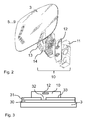
- FIGS. 1 and 2 show a plan view and an exploded view of an outside mirror of a motor vehicle, in which lighting elements are mounted on the mirror glass.
- FIG. 3 shows a section through mirror and light module.
- FIG. 1 shows an exterior mirror 1, which comprises a mirror housing 2, a mirror glass 3, a servomotor 4 for adjusting the mirror and lighting elements 5 to 9.
- the light-emitting elements are in the embodiment shown from the rear of the mirror glass, ie mounted on the not visible from the driver side of the glass, preferably glued. These light-emitting elements are actuated to warn the driver in certain situations, in the preferred embodiment by a blind spot detection system, when it detects a road user in the blind spot of the vehicle. In this case, the lighting elements are illuminated, whereby the driver is made aware of the danger by the illumination of the mirror.
- the lighting elements are mounted in the outer region of the exterior mirror on the side facing away from the motor vehicle.
- the light-emitting elements 5 to 9 represent in the preferred embodiment, light-emitting diodes, which are housed from the back along with their leads in a housing and glued to the mirror glass.
- FIG. 2 shows an exploded view of the in FIG. 1 illustrated exterior mirror with a light module according to the prior art.
- the display symbols 5 to 9 to be displayed can be seen on the left of the mirror glass 3 as a recess from the reflective layer.
- the actual light module 10 has a housing with luminous elements 12, which is covered by a masking plane 13.
- the mask plane 13 has recesses 14, which correspond to the symbols to be displayed.
- Such light modules are provided with an adhesive layer on the mask plane 13 and glued to the back of the mirror glass 3.
- the invention uses a different approach.
- the light module according to the invention has a transparent cover plate which is irradiated over the entire surface.
- the transparent cover plate closes the housing 11 and backlightens the symbols that are to be displayed.
- the light module has no mask function.
- the mirror glass 3 is conventionally mirrored with a metal layer such as a chromium or titanium or aluminum layer 30, special mirror layers or dielectric layers are not necessary.
- the mirror glass is coated after the coating with a colored lacquer or a colored plastic layer 31.
- the coating 31 serves to prevent mirror breakage when the mirror glasses are being assembled.
- this colored, preferably black lacquer layer 31 serves to prevent any reflections from the back of the mirror glass and to prevent residual transparency.
- aspherical lenses are approved. These are convex-curved glasses with an aspherical additional area that has variable radii. This additional area must be marked with a delimitation mark for the approval of the glasses according to the European directives.
- the mirror glass backside is already structured with a laser. Since this manufacturing step is already provided in the manufacture of the outside mirror, it is advantageous to manufacture the symbol to be displayed in the same step.
- the symbol is written with a laser, which is to be displayed.
- the lacquer layer is selectively removed. In this case, a partial removal of the mirror layer 30 is conceivable.
- the reflective layer is partially preserved to achieve a diffuse light appearance. A few nanometers of the metal layer is sufficient.
- the lacquer layer and the reflective material are completely removed from the rear side of the mirror glass.
- the light module 10 is not sealed by a cover plate 13, but is glued or clamped directly on the back of the mirror.
- the end faces of the housing are used. If necessary, these faces are widened to get more adhesive surface.
- the light module contains only the electrical connections of the LED 12, and a housing 11, which terminates flush with the lens. All types of fastening that would be provided by a person skilled in the art for fixing the module are permitted.
- the light module 10 covers a surface 33 of the mirror glass back. In the ready of the surface 33, the colored layer 31 is structured.
- the structure 32 is generated with a laser beam which vaporizes symbols out of the layer.
- Symbols are warning signs, or ISO standardized representations for danger warnings, as well as individual customer-specific displays.
- the advantage of the invention is that the light module does not have to be mounted precisely over the symbol. The assembly of the light module is simplified. If enough light is available, the symbol is sufficiently irradiated.
- Lighting elements and their type depends on the application. In the simplest case, a luminous element is sufficient.
- corresponding display concepts are used in conjunction with other functions, such as parking aids, etc. This applies to all the functions where it is assumed that the driver is looking into one of the mirrors of the vehicle for monitoring the rear area of the vehicle.
- the display is used depending on the design in a suitable selection of existing mirrors or in all existing mirrors.
Abstract
Description
Die Erfindung betrifft eine Anzeige bei einem Kraftfahrzeug, die in einem Außenspiegel positioniert ist. Weiterhin betrifft die Erfindung die Herstellung einer solchen Anzeige.The invention relates to a display in a motor vehicle, which is positioned in an exterior mirror. Furthermore, the invention relates to the production of such a display.
In der Kraftfahrzeugtechnik gibt es eine Vielzahl von Funktionen, welche Anzeigen bedienen, beispielsweise Warnlampen. Ein Beispiel für eine solche Funktion ist ein Tote-Winkel-Detektionssystem. Mittels Sensoren, beispielsweise optischen Sensoren, Ultraschall- oder Radarsensoren, werden bei diesen Detektionssystemen Verkehrsteilnehmer im Tote-Winkel-Bereich erkannt und bei erkanntem Verkehrsteilnehmer in diesem Bereich eine Warnleuchte betätigt, die im Innenraum im Bereich des Außenspiegels an der A-Säule des Fahrzeugs montiert ist, oder sich hinter dem Spiegelglass eines Außenspiegels befindet.
Andere Funktionen, die Anzeigen bedienen, sind beispielsweise Einparkhilfen oder ähnliches, bei denen der Abstand zu einem rückwärtigen Fahrzeug visualisiert wird und/oder eine Warnlampe betätigt wird, wenn der Abstand ein Minimalwert unterschreitet.In automotive engineering, there are a variety of functions that serve displays, such as warning lights. An example of such a function is a dead-angle detection system. By means of sensors, for example optical sensors, ultrasound or radar sensors, road users in the blind spot area are detected in these detection systems and a warning light is actuated when the road user is detected in this area, which is mounted in the interior in the area of the exterior mirror on the A pillar of the vehicle is or is behind the mirror glass of an exterior mirror.
Other functions that serve displays are, for example, parking aids or the like, in which the distance to a rear vehicle is visualized and / or a warning lamp is actuated when the distance is below a minimum value.
Derartige Anzeigen sind aufgrund ihrer Aufgabe so zu gestalten, dass sie vom Fahrer in der jeweiligen Situation nicht übersehen werden. Dies könnte z. B. bei einem Tote- Winkel-Detektionssystem bei dem Anbringen der Warnleuchte im Bereich der A-Säule oder bei Einparkhilfen bei Anzeigen im Bereich des Kombiinstruments des Fahrzeugs jedoch der Fall sein.Such displays are due to their task to be designed so that they are not overlooked by the driver in each situation. This could be z. However, for example, in a blind spot detection system when attaching the warning light in the A-pillar or parking aids in displays in the range of the instrument cluster of the vehicle to be the case.
Aus dem Stand der Technik sind eine Vielzahl solcher Anzeigen hinter dem Spiegelglas bekannt. Dabei werden vorzugsweise dichroische Spiegel oder semitransparente Spiegel eingesetzt.From the prior art, a plurality of such displays are known behind the mirror glass. In this case, dichroic mirrors or semitransparent mirrors are preferably used.
Aus der
Nachteilig ist der komplexe Aufbau des Spiegels mit der Beleuchtung und die Verwendung eines semitransparenten Spiegels.A disadvantage is the complex structure of the mirror with the lighting and the use of a semi-transparent mirror.
Der wesentliche Vorteil der Anzeige ist darin zu sehen, dass zur Anzeige keine sichtbaren Bauteile erforderlich sind, ebenso wenig Sonderbauteile, wie beispielsweise halbdurchlässige Spiegelgläser. Damit können undurchlässige Spiegelgläser weiterhin eingesetzt werden.The main advantage of the display is the fact that no visible components are required to display, as well as special components, such as semi-transparent mirror glasses. This impermeable mirror glasses can continue to be used.
Weiter vorteilhaft ist, dass Heizfolien zur Enteisung der Spiegel im Winter, weiterhin verwendbar sind. Ebenso vorteilhaft ist, dass keine umfangreichen Modifikationen am Spiegelgehäuse notwendig sind, speziell falls die Anzeigeelemente von hinten an das Spiegelglas eines Spiegels angebracht werden. Außerdem kann somit eine Anzeige mit hoher Leuchtstärke bei geringem Energieverbrauch realisiert werden, ohne den Fahrer zu blenden.It is also advantageous that heating films for deicing the mirror in winter, continue to be used. It is also advantageous that no extensive modifications to the mirror housing are necessary, especially if the display elements are attached from the rear to the mirror glass of a mirror. In addition, thus, a display with high luminosity can be realized with low power consumption, without dazzling the driver.
Besonders vorteilhaft ist die Art der Anzeige in Verbindung mit einem Tote-Winkel-Warnsystem, da bei einem Spurwechsel auch bei vorhandenem Warnsystem weiterhin der Blick des Fahrers in den Außenspiegel erforderlich ist, um weiter zurückliegende Fahrzeuge zu erkennen und gegebenenfalls einen Spurwechsel zu unterlassen. Die Anzeige erfolgt bei einem beabsichtigten Spurwechsel in dieser Anwendung daher im direkten Sichtfeld des Fahrers.Particularly advantageous is the type of display in conjunction with a tote-angle warning system, as in a lane change even with existing warning system continues the driver's gaze is required in the exterior mirrors to recognize vehicles further behind and optionally omit a lane change. The display is therefore at an intended lane change in this application in the direct field of view of the driver.
Besonders einfach werden die Leuchtelemente an das Spiegelglas mittels Kleben angebracht. In vorteilhafter Weise werden dabei helle Leuchtdioden verwendet, die eine besonders kostengünstige Realisierung bei hoher Leuchtstärke darstellen. Besonders vorteilhaft ist die Verwendung mehrerer Leuchtelemente, welche im Außenbereich des Spiegels, bei einem Außenspiegel vorzugsweise an einem vom Fahrzeug abgewandten Teil des Außenspiegels angebracht sind. Dadurch wird eine besonders effektive Anzeige mit einer besonders hohen Warnwirkung für den Fahrer erreicht, die zugleich nicht im ständigen Sichtfeld des Fahrers liegt.The light elements are attached to the mirror glass by means of gluing. In this case, light emitting diodes are advantageously used, which represent a particularly cost-effective implementation with high luminous intensity. Particularly advantageous is the use of a plurality of lighting elements which are mounted in the outer region of the mirror, in the case of an exterior mirror, preferably on a part of the exterior mirror facing away from the vehicle. As a result, a particularly effective display with a particularly high warning effect for the driver is achieved, which is also not in the constant field of vision of the driver.
In anderen Anwendungen, beispielsweise bei Einparkhilfen, bei denen die Leuchtdioden im Innenrückspiegel und/oder im Außenspiegel angebracht werden können, zeigen sich die entsprechenden Vorteile. Weitere Vorteile ergeben sich aus der nachfolgenden Beschreibung von Ausführungsbeispielen bzw. aus den abhängigen Ansprüchen.In other applications, such as parking aids, in which the LEDs can be mounted in the interior rearview mirror and / or in the exterior mirror, the corresponding benefits show. Further advantages will become apparent from the following description of exemplary embodiments or from the dependent claims.
Die Erfindung wird nachfolgend anhand der in der Zeichnung dargestellten Ausführungsformen näher erläutert. Die
Im bevorzugten Ausführungsbeispiel sind die Leuchtelemente im Außenbereich des Außenspiegels auf der vom Kraftfahrzeug wegweisenden Seite angebracht.In the preferred embodiment, the lighting elements are mounted in the outer region of the exterior mirror on the side facing away from the motor vehicle.
In anderen Ausführungen hat es sich als geeignet erwiesen, ergänzend oder alternativ andere Bereiche des Außenspiegels mit Leuchtelementen, eventuell auch in verschiedenen Farben, zu versehen. Dadurch wird eine andere, bei gleichmäßiger Verteilung der Leuchtelemente über die Spiegelglasfläche verschiedene Anzeigenmuster dargestellt. Bei der gleichmäßigen Verteilung z. B. wird eine Beleuchtung entlang des gesamten Randes des Spiegelgehäuses erreicht. Bei der Verwendung unterschiedlicher Farben können somit unterschiedliche Informationen vermittelt werden.In other embodiments, it has proven to be suitable to supplement or alternatively provide other areas of the exterior mirror with lighting elements, possibly also in different colors. As a result, a different display pattern is displayed, with uniform distribution of the luminous elements across the mirror glass surface. In the uniform distribution z. B. lighting is achieved along the entire edge of the mirror housing. When using different colors, therefore, different information can be conveyed.
Die Leuchtelemente 5 bis 9 stellen im bevorzugten Ausführungsbeispiel helle Leuchtdioden dar, die von hinten samt ihrer Zuleitungen in einem Gehäuse untergebracht und an das Spiegelglas geklebt sind.The light-emitting
Solche Lichtmodule, die von hinten auf das semitransparente Spiegelglas geklebt werden, sind auch aus der
Das eigentliche Lichtmodul 10 weist ein Gehäuse mit Leuchtelementen 12 auf, das von einer Maskenebene 13 abgedeckt wird. Die Maskenebene 13 weist Aussparungen 14 auf, die den darzustellenden Symbolen entsprechen. Solche Lichtmodule werden mit einer Klebeschicht auf der Maskenebene 13 versehen und auf die Rückseite des Spiegelglases 3 geklebt.The
Demgegenüber verwendet die Erfindung anderen Ansatz. Das erfindungsgemäße Lichtmodul weist in einer Ausführungsform eine transparente Abdeckplatte auf, die vollflächig durchstrahlt wird. Die transparente Abdeckplatte verschließt das Gehäuse 11 und hinterleuchtet die Symbole, die angezeigt werden sollen. Das Lichtmodul weist keine Maskenfunktion auf.In contrast, the invention uses a different approach. In one embodiment, the light module according to the invention has a transparent cover plate which is irradiated over the entire surface. The transparent cover plate closes the
Die darzustellenden Symbole werden direkt auf dem Spiegel eingebracht. Dazu wird das Spiegelglas 3 konventionell mit einer Metallschicht wie einer Chrom- oder Titan- oder Aluminiumschicht 30 verspiegelt, spezielle Spiegelschichten oder dielektrische Schichten sind nicht notwendig.The symbols to be displayed are placed directly on the mirror. For this purpose, the
Das Spiegelglas wird nach der Beschichtung mit einem farbigen Lack oder einer farbigen Kunststoffschicht 31 überzogen. Die Beschichtung 31dient zum einen in der Herstellung zur Vermeidung von Spiegelbruch, wenn die Spiegelgläser konfektioniert werden. Zum anderen dient diese farbige, vorzugsweise schwarze Lackschicht 31 dazu eventuelle Reflektionen von der Rückseite des Spiegelglases zu verhindern und eine Restdurchsichtigkeit zu unterbinden.The mirror glass is coated after the coating with a colored lacquer or a colored
Für Fahrzeuge in der EU sind asphärische Gläser zugelassen. Es handelt sich dabei um konvex gewölbte Gläser mit einem asphärischen Zusatzbereich, der variable Radien aufweist. Dieser Zusatzbereich muss für die Zulassung der Gläser nach den Europäischen Richtlinien mit einem Begrenzungsstrich markiert werden.For vehicles in the EU, aspherical lenses are approved. These are convex-curved glasses with an aspherical additional area that has variable radii. This additional area must be marked with a delimitation mark for the approval of the glasses according to the European directives.
Dazu wird schon heute die Spiegelglasrückseite mit einem Laser strukturiert. Da dieser Herstellungsschritt in der Herstellung des Außenspiegels bereits vorgesehen ist, ist es von Vorteil, das anzuzeigende Symbol in demselben Schritt herzustellen.For this purpose, the mirror glass backside is already structured with a laser. Since this manufacturing step is already provided in the manufacture of the outside mirror, it is advantageous to manufacture the symbol to be displayed in the same step.
In die Lackschicht 31 wird mit einem Laser das Symbol eingeschrieben, das dargestellt werden soll. Die Lackschicht wird dazu selektiv entfernt. Dabei ist auch ein Teilabtrag der Spiegelschicht 30 denkbar. Die reflektierende Schicht bleibt zum Teil erhalten, um eine diffuse Lichterscheinung zu erzielen. Einige Nanometer der Metallschicht reicht dazu aus.In the
In einer weiteren Ausführungsform werden die Lackschicht und das reflektierende Material zur Gänze von der Rückseite des Spiegelglases abgetragen.In a further embodiment, the lacquer layer and the reflective material are completely removed from the rear side of the mirror glass.
In der In
Die ausreichende Beleuchtung kann weitere Maßnahmen im Lichtmodul notwendig machen, wie Reflektoren, oder Optiken. Die Anzahl der verwendetenSufficient illumination may necessitate further measures in the light module, such as reflectors or optics. The number of used
Leuchtelemente und ihre Art ist von der Anwendung abhängig. Im einfachsten Fall reicht ein Leuchtelement aus.Lighting elements and their type depends on the application. In the simplest case, a luminous element is sufficient.
Anstelle der Anwendung in Verbindung mit einem Toten-Winkel- Detektionssystem werden entsprechende Anzeigenkonzepte in Verbindung mit anderen Funktionen, beispielsweise Einparkhilfen, etc. eingesetzt. Dies gilt für alle die Funktionen, bei denen davon auszugehen ist, dass der Fahrer in einen der Spiegel des Fahrzeugs zur Überwachung des rückwärtigen Bereichs des Fahrzeugs blickt. Die Anzeige ist dabei je nach Ausführung in einer geeigneten Auswahl der vorhandenen Spiegel oder in allen vorhandenen Spiegel eingesetzt.Instead of the application in conjunction with a dead-angle detection system corresponding display concepts are used in conjunction with other functions, such as parking aids, etc. This applies to all the functions where it is assumed that the driver is looking into one of the mirrors of the vehicle for monitoring the rear area of the vehicle. The display is used depending on the design in a suitable selection of existing mirrors or in all existing mirrors.
Claims (9)
Applications Claiming Priority (1)
| Application Number | Priority Date | Filing Date | Title |
|---|---|---|---|
| DE102010032026A DE102010032026A1 (en) | 2010-07-13 | 2010-07-13 | Display in the mirror glass and method of manufacture |
Publications (2)
| Publication Number | Publication Date |
|---|---|
| EP2407347A1 true EP2407347A1 (en) | 2012-01-18 |
| EP2407347B1 EP2407347B1 (en) | 2016-05-04 |
Family
ID=44118259
Family Applications (1)
| Application Number | Title | Priority Date | Filing Date |
|---|---|---|---|
| EP11168801.6A Active EP2407347B1 (en) | 2010-07-13 | 2011-06-06 | Display in the mirror glass and process for production |
Country Status (3)
| Country | Link |
|---|---|
| US (1) | US8783881B2 (en) |
| EP (1) | EP2407347B1 (en) |
| DE (1) | DE102010032026A1 (en) |
Cited By (1)
| Publication number | Priority date | Publication date | Assignee | Title |
|---|---|---|---|---|
| WO2017137198A1 (en) * | 2016-02-11 | 2017-08-17 | Magna Mirrors Holding Gmbh | Method for detecting vehicles, and exterior vehicle mirror |
Families Citing this family (13)
| Publication number | Priority date | Publication date | Assignee | Title |
|---|---|---|---|---|
| US8786704B2 (en) | 2007-08-09 | 2014-07-22 | Donnelly Corporation | Vehicle mirror assembly with wide angle element |
| JP5803258B2 (en) | 2010-09-30 | 2015-11-04 | セイコーエプソン株式会社 | UV-curable ink composition for ink jet and ink jet recording method |
| US9056986B2 (en) | 2010-11-09 | 2015-06-16 | Seiko Epson Corporation | Ultraviolet curable type ink-jet ink composition, recording method and recording apparatus using same |
| EP2597634B1 (en) * | 2011-11-25 | 2014-02-26 | SkiData AG | Display device |
| US10744947B2 (en) * | 2012-01-24 | 2020-08-18 | SMR Patents S.à.r.l. | Head section for a rear view device |
| DE102012108480B3 (en) * | 2012-09-11 | 2014-02-20 | SMR Patents S.à.r.l. | headboard |
| CN107379803A (en) | 2012-03-28 | 2017-11-24 | 精工爱普生株式会社 | Ink jet recording method, ultraviolet curable ink, ink-jet recording apparatus |
| JP6191120B2 (en) | 2012-03-29 | 2017-09-06 | セイコーエプソン株式会社 | Ink jet recording method and ink jet recording apparatus |
| US10029483B2 (en) | 2012-04-25 | 2018-07-24 | Seiko Epson Corporation | Ink jet recording method, ultraviolet-ray curable ink, and ink jet recording apparatus |
| JP6236768B2 (en) | 2012-04-27 | 2017-11-29 | セイコーエプソン株式会社 | Ink jet recording method and ink jet recording apparatus |
| JP6065535B2 (en) | 2012-11-15 | 2017-01-25 | セイコーエプソン株式会社 | UV-curable ink composition for ink jet recording, ink container, and ink jet recording apparatus |
| CN107139844A (en) * | 2017-06-22 | 2017-09-08 | 厦门澳仕达电子有限公司 | A kind of vehicle blind zone detection alarm warning light processing method and system |
| US11215922B2 (en) * | 2019-07-12 | 2022-01-04 | E-Lan Car Components (USA) Inc. | Method for manufacturing a color slide for an automobile projection lamp |
Citations (9)
| Publication number | Priority date | Publication date | Assignee | Title |
|---|---|---|---|---|
| US6005724A (en) * | 1998-10-05 | 1999-12-21 | K. W. Muth Company, Inc. | Mirror coating, mirror utilizing same, and a mirror assembly |
| DE29921059U1 (en) * | 1999-11-30 | 2000-03-02 | Ju Chong An | Mirror with a bright pattern or lettering |
| WO2000030893A1 (en) * | 1998-11-23 | 2000-06-02 | Lear Automotive Dearborn, Inc. | Exterior mirror with supplemental turn signal |
| EP1022190A2 (en) * | 1999-01-22 | 2000-07-26 | MEKRA Lang GmbH & Co. KG | Rear view mirror |
| US7327321B2 (en) | 2005-06-27 | 2008-02-05 | K.W. Muth Company, Inc. | Electromagnetic radiation assembly |
| US20080030835A1 (en) * | 1999-05-14 | 2008-02-07 | Tonar William L | Electrochromic rearview mirror incorporating a third surface reflector |
| WO2008051910A2 (en) * | 2006-10-24 | 2008-05-02 | Donnelly Corporation | Display device for exterior mirror |
| EP2042373A2 (en) | 2007-09-28 | 2009-04-01 | Murakami Corporation | Vehicle rear-view mirror |
| US7717596B1 (en) * | 2005-07-15 | 2010-05-18 | Alan Bell | Rearview mirror assembly with running lights |
Family Cites Families (5)
| Publication number | Priority date | Publication date | Assignee | Title |
|---|---|---|---|---|
| US6076948A (en) * | 1998-10-28 | 2000-06-20 | K. W. Muth Company, Inc. | Electromagnetic radiation emitting or receiving assembly |
| US7581859B2 (en) * | 2005-09-14 | 2009-09-01 | Donnelly Corp. | Display device for exterior rearview mirror |
| EP1514246A4 (en) * | 2002-06-06 | 2008-04-16 | Donnelly Corp | Interior rearview mirror system with compass |
| DE20218383U1 (en) * | 2002-11-27 | 2003-02-13 | Fer Fahrzeugelektrik Gmbh | Mirror has a flat surface capacitor built into the rear of the mirror for lighting |
| US7626749B2 (en) * | 2005-05-16 | 2009-12-01 | Donnelly Corporation | Vehicle mirror assembly with indicia at reflective element |
-
2010
- 2010-07-13 DE DE102010032026A patent/DE102010032026A1/en not_active Ceased
-
2011
- 2011-06-06 EP EP11168801.6A patent/EP2407347B1/en active Active
- 2011-07-13 US US13/181,648 patent/US8783881B2/en active Active
Patent Citations (9)
| Publication number | Priority date | Publication date | Assignee | Title |
|---|---|---|---|---|
| US6005724A (en) * | 1998-10-05 | 1999-12-21 | K. W. Muth Company, Inc. | Mirror coating, mirror utilizing same, and a mirror assembly |
| WO2000030893A1 (en) * | 1998-11-23 | 2000-06-02 | Lear Automotive Dearborn, Inc. | Exterior mirror with supplemental turn signal |
| EP1022190A2 (en) * | 1999-01-22 | 2000-07-26 | MEKRA Lang GmbH & Co. KG | Rear view mirror |
| US20080030835A1 (en) * | 1999-05-14 | 2008-02-07 | Tonar William L | Electrochromic rearview mirror incorporating a third surface reflector |
| DE29921059U1 (en) * | 1999-11-30 | 2000-03-02 | Ju Chong An | Mirror with a bright pattern or lettering |
| US7327321B2 (en) | 2005-06-27 | 2008-02-05 | K.W. Muth Company, Inc. | Electromagnetic radiation assembly |
| US7717596B1 (en) * | 2005-07-15 | 2010-05-18 | Alan Bell | Rearview mirror assembly with running lights |
| WO2008051910A2 (en) * | 2006-10-24 | 2008-05-02 | Donnelly Corporation | Display device for exterior mirror |
| EP2042373A2 (en) | 2007-09-28 | 2009-04-01 | Murakami Corporation | Vehicle rear-view mirror |
Cited By (1)
| Publication number | Priority date | Publication date | Assignee | Title |
|---|---|---|---|---|
| WO2017137198A1 (en) * | 2016-02-11 | 2017-08-17 | Magna Mirrors Holding Gmbh | Method for detecting vehicles, and exterior vehicle mirror |
Also Published As
| Publication number | Publication date |
|---|---|
| US20120014005A1 (en) | 2012-01-19 |
| US8783881B2 (en) | 2014-07-22 |
| EP2407347B1 (en) | 2016-05-04 |
| DE102010032026A1 (en) | 2012-01-19 |
Similar Documents
| Publication | Publication Date | Title |
|---|---|---|
| EP2407347B1 (en) | Display in the mirror glass and process for production | |
| EP1970736B1 (en) | Outside rear view mirror for vehicles, especially for motor vehicles | |
| EP1840626B1 (en) | Head-up display, motor vehicle und method for operating a head-up display | |
| EP2762361B1 (en) | Lighting unit | |
| DE102009046325A1 (en) | Instrument panel and instrument with ultraviolet signs | |
| DE102015225343B4 (en) | Means of locomotion and arrangement for a means of locomotion for outputting direction-analogous information on details of the surroundings | |
| DE102015115242A1 (en) | Vehicle with light projection system and method for creating a safety area on a ground surface | |
| DE102009010623A1 (en) | Device for issuing visual warning information to driver of vehicle, particularly motor vehicle, has vehicle window pane, through which vehicle driver visually captures area of environment of vehicle | |
| DE102016212527A1 (en) | Blink unit for an exterior mirror | |
| WO2020043532A1 (en) | Lighting apparatus for a motor vehicle | |
| DE102015008158A1 (en) | Optical fiber and lighting device for generating a floating luminous graphics for ambient lighting in a vehicle, preferably in vehicle attachments | |
| EP1856684B1 (en) | Self-luminous indicator panel and method for the production thereof | |
| DE102012211821A1 (en) | Lamp unit e.g. tail light unit, integrated in mirror housing unit of motor vehicle, has transparent window portion formed in housing shell, and light-guiding elements formed in one-piece with shell during molding process | |
| DE102019125265A1 (en) | Optical arrangement, headlights, vehicle and procedures | |
| DE102013225796A1 (en) | Luminaire unit for a motor vehicle | |
| EP1478546B1 (en) | Display device for a motor vehicle | |
| DE102012005076A1 (en) | Fascia for motor vehicle, has transparent cover that is arranged in vehicle, and display panel comprising transparent light guide plate, where light guide plate comprises light-scattering nanoparticle in its volume | |
| DE102013225795B4 (en) | Optical display in an exterior mirror and method of making an optical display | |
| EP3792111B1 (en) | Lamp | |
| EP2565527A1 (en) | Signal lamp for motor vehicles | |
| DE102011016421A1 (en) | Instrument panel for motor vehicle, has transparent instrument panel cover having transparent light guide plate with volume of light-scattering nanoparticles distributed at region of warning area | |
| DE102011016432A1 (en) | Windscreen for motor vehicle, has cohesively connected glass and plastic layers, and rim surrounding windscreen, where display area has optical fiber material | |
| EP2500629B1 (en) | Rearview mirror for a vehicle with lighting units with micro-optics | |
| DE102013012481A1 (en) | Motor vehicle roof window element with a lighting arrangement | |
| DE102012017346A1 (en) | Lighting device e.g. side marker light for vehicle, has transparent optical component that is arranged between reflector and light-transmitting cover |
Legal Events
| Date | Code | Title | Description |
|---|---|---|---|
| AK | Designated contracting states |
Kind code of ref document: A1 Designated state(s): AL AT BE BG CH CY CZ DE DK EE ES FI FR GB GR HR HU IE IS IT LI LT LU LV MC MK MT NL NO PL PT RO RS SE SI SK SM TR |
|
| AX | Request for extension of the european patent |
Extension state: BA ME |
|
| PUAI | Public reference made under article 153(3) epc to a published international application that has entered the european phase |
Free format text: ORIGINAL CODE: 0009012 |
|
| 17P | Request for examination filed |
Effective date: 20120709 |
|
| 17Q | First examination report despatched |
Effective date: 20140811 |
|
| GRAP | Despatch of communication of intention to grant a patent |
Free format text: ORIGINAL CODE: EPIDOSNIGR1 |
|
| INTG | Intention to grant announced |
Effective date: 20151126 |
|
| GRAR | Information related to intention to grant a patent recorded |
Free format text: ORIGINAL CODE: EPIDOSNIGR71 |
|
| GRAS | Grant fee paid |
Free format text: ORIGINAL CODE: EPIDOSNIGR3 |
|
| GRAA | (expected) grant |
Free format text: ORIGINAL CODE: 0009210 |
|
| INTG | Intention to grant announced |
Effective date: 20160322 |
|
| AK | Designated contracting states |
Kind code of ref document: B1 Designated state(s): AL AT BE BG CH CY CZ DE DK EE ES FI FR GB GR HR HU IE IS IT LI LT LU LV MC MK MT NL NO PL PT RO RS SE SI SK SM TR |
|
| REG | Reference to a national code |
Ref country code: GB Ref legal event code: FG4D Free format text: NOT ENGLISH |
|
| REG | Reference to a national code |
Ref country code: CH Ref legal event code: EP |
|
| REG | Reference to a national code |
Ref country code: AT Ref legal event code: REF Ref document number: 796600 Country of ref document: AT Kind code of ref document: T Effective date: 20160515 |
|
| REG | Reference to a national code |
Ref country code: IE Ref legal event code: FG4D Free format text: LANGUAGE OF EP DOCUMENT: GERMAN |
|
| REG | Reference to a national code |
Ref country code: DE Ref legal event code: R096 Ref document number: 502011009631 Country of ref document: DE |
|
| REG | Reference to a national code |
Ref country code: FR Ref legal event code: PLFP Year of fee payment: 6 |
|
| REG | Reference to a national code |
Ref country code: NL Ref legal event code: MP Effective date: 20160504 |
|
| REG | Reference to a national code |
Ref country code: LT Ref legal event code: MG4D |
|
| PG25 | Lapsed in a contracting state [announced via postgrant information from national office to epo] |
Ref country code: LT Free format text: LAPSE BECAUSE OF FAILURE TO SUBMIT A TRANSLATION OF THE DESCRIPTION OR TO PAY THE FEE WITHIN THE PRESCRIBED TIME-LIMIT Effective date: 20160504 Ref country code: FI Free format text: LAPSE BECAUSE OF FAILURE TO SUBMIT A TRANSLATION OF THE DESCRIPTION OR TO PAY THE FEE WITHIN THE PRESCRIBED TIME-LIMIT Effective date: 20160504 Ref country code: NL Free format text: LAPSE BECAUSE OF FAILURE TO SUBMIT A TRANSLATION OF THE DESCRIPTION OR TO PAY THE FEE WITHIN THE PRESCRIBED TIME-LIMIT Effective date: 20160504 Ref country code: NO Free format text: LAPSE BECAUSE OF FAILURE TO SUBMIT A TRANSLATION OF THE DESCRIPTION OR TO PAY THE FEE WITHIN THE PRESCRIBED TIME-LIMIT Effective date: 20160804 |
|
| PG25 | Lapsed in a contracting state [announced via postgrant information from national office to epo] |
Ref country code: ES Free format text: LAPSE BECAUSE OF FAILURE TO SUBMIT A TRANSLATION OF THE DESCRIPTION OR TO PAY THE FEE WITHIN THE PRESCRIBED TIME-LIMIT Effective date: 20160504 Ref country code: SE Free format text: LAPSE BECAUSE OF FAILURE TO SUBMIT A TRANSLATION OF THE DESCRIPTION OR TO PAY THE FEE WITHIN THE PRESCRIBED TIME-LIMIT Effective date: 20160504 Ref country code: GR Free format text: LAPSE BECAUSE OF FAILURE TO SUBMIT A TRANSLATION OF THE DESCRIPTION OR TO PAY THE FEE WITHIN THE PRESCRIBED TIME-LIMIT Effective date: 20160805 Ref country code: LV Free format text: LAPSE BECAUSE OF FAILURE TO SUBMIT A TRANSLATION OF THE DESCRIPTION OR TO PAY THE FEE WITHIN THE PRESCRIBED TIME-LIMIT Effective date: 20160504 Ref country code: PT Free format text: LAPSE BECAUSE OF FAILURE TO SUBMIT A TRANSLATION OF THE DESCRIPTION OR TO PAY THE FEE WITHIN THE PRESCRIBED TIME-LIMIT Effective date: 20160905 Ref country code: HR Free format text: LAPSE BECAUSE OF FAILURE TO SUBMIT A TRANSLATION OF THE DESCRIPTION OR TO PAY THE FEE WITHIN THE PRESCRIBED TIME-LIMIT Effective date: 20160504 Ref country code: RS Free format text: LAPSE BECAUSE OF FAILURE TO SUBMIT A TRANSLATION OF THE DESCRIPTION OR TO PAY THE FEE WITHIN THE PRESCRIBED TIME-LIMIT Effective date: 20160504 |
|
| PG25 | Lapsed in a contracting state [announced via postgrant information from national office to epo] |
Ref country code: IT Free format text: LAPSE BECAUSE OF FAILURE TO SUBMIT A TRANSLATION OF THE DESCRIPTION OR TO PAY THE FEE WITHIN THE PRESCRIBED TIME-LIMIT Effective date: 20160504 Ref country code: BE Free format text: LAPSE BECAUSE OF NON-PAYMENT OF DUE FEES Effective date: 20160630 |
|
| PG25 | Lapsed in a contracting state [announced via postgrant information from national office to epo] |
Ref country code: SK Free format text: LAPSE BECAUSE OF FAILURE TO SUBMIT A TRANSLATION OF THE DESCRIPTION OR TO PAY THE FEE WITHIN THE PRESCRIBED TIME-LIMIT Effective date: 20160504 Ref country code: CZ Free format text: LAPSE BECAUSE OF FAILURE TO SUBMIT A TRANSLATION OF THE DESCRIPTION OR TO PAY THE FEE WITHIN THE PRESCRIBED TIME-LIMIT Effective date: 20160504 Ref country code: EE Free format text: LAPSE BECAUSE OF FAILURE TO SUBMIT A TRANSLATION OF THE DESCRIPTION OR TO PAY THE FEE WITHIN THE PRESCRIBED TIME-LIMIT Effective date: 20160504 Ref country code: DK Free format text: LAPSE BECAUSE OF FAILURE TO SUBMIT A TRANSLATION OF THE DESCRIPTION OR TO PAY THE FEE WITHIN THE PRESCRIBED TIME-LIMIT Effective date: 20160504 Ref country code: RO Free format text: LAPSE BECAUSE OF FAILURE TO SUBMIT A TRANSLATION OF THE DESCRIPTION OR TO PAY THE FEE WITHIN THE PRESCRIBED TIME-LIMIT Effective date: 20160504 |
|
| REG | Reference to a national code |
Ref country code: CH Ref legal event code: PL |
|
| REG | Reference to a national code |
Ref country code: DE Ref legal event code: R097 Ref document number: 502011009631 Country of ref document: DE |
|
| PG25 | Lapsed in a contracting state [announced via postgrant information from national office to epo] |
Ref country code: SM Free format text: LAPSE BECAUSE OF FAILURE TO SUBMIT A TRANSLATION OF THE DESCRIPTION OR TO PAY THE FEE WITHIN THE PRESCRIBED TIME-LIMIT Effective date: 20160504 Ref country code: PL Free format text: LAPSE BECAUSE OF FAILURE TO SUBMIT A TRANSLATION OF THE DESCRIPTION OR TO PAY THE FEE WITHIN THE PRESCRIBED TIME-LIMIT Effective date: 20160504 |
|
| PLBE | No opposition filed within time limit |
Free format text: ORIGINAL CODE: 0009261 |
|
| STAA | Information on the status of an ep patent application or granted ep patent |
Free format text: STATUS: NO OPPOSITION FILED WITHIN TIME LIMIT |
|
| REG | Reference to a national code |
Ref country code: IE Ref legal event code: MM4A |
|
| PG25 | Lapsed in a contracting state [announced via postgrant information from national office to epo] |
Ref country code: MC Free format text: LAPSE BECAUSE OF FAILURE TO SUBMIT A TRANSLATION OF THE DESCRIPTION OR TO PAY THE FEE WITHIN THE PRESCRIBED TIME-LIMIT Effective date: 20160504 |
|
| 26N | No opposition filed |
Effective date: 20170207 |
|
| PG25 | Lapsed in a contracting state [announced via postgrant information from national office to epo] |
Ref country code: LI Free format text: LAPSE BECAUSE OF NON-PAYMENT OF DUE FEES Effective date: 20160630 Ref country code: CH Free format text: LAPSE BECAUSE OF NON-PAYMENT OF DUE FEES Effective date: 20160630 |
|
| PG25 | Lapsed in a contracting state [announced via postgrant information from national office to epo] |
Ref country code: IE Free format text: LAPSE BECAUSE OF NON-PAYMENT OF DUE FEES Effective date: 20160606 Ref country code: SI Free format text: LAPSE BECAUSE OF FAILURE TO SUBMIT A TRANSLATION OF THE DESCRIPTION OR TO PAY THE FEE WITHIN THE PRESCRIBED TIME-LIMIT Effective date: 20160504 |
|
| REG | Reference to a national code |
Ref country code: FR Ref legal event code: PLFP Year of fee payment: 7 |
|
| REG | Reference to a national code |
Ref country code: AT Ref legal event code: MM01 Ref document number: 796600 Country of ref document: AT Kind code of ref document: T Effective date: 20160606 |
|
| PG25 | Lapsed in a contracting state [announced via postgrant information from national office to epo] |
Ref country code: AT Free format text: LAPSE BECAUSE OF NON-PAYMENT OF DUE FEES Effective date: 20160606 |
|
| PG25 | Lapsed in a contracting state [announced via postgrant information from national office to epo] |
Ref country code: CY Free format text: LAPSE BECAUSE OF FAILURE TO SUBMIT A TRANSLATION OF THE DESCRIPTION OR TO PAY THE FEE WITHIN THE PRESCRIBED TIME-LIMIT Effective date: 20160504 Ref country code: HU Free format text: LAPSE BECAUSE OF FAILURE TO SUBMIT A TRANSLATION OF THE DESCRIPTION OR TO PAY THE FEE WITHIN THE PRESCRIBED TIME-LIMIT; INVALID AB INITIO Effective date: 20110606 |
|
| REG | Reference to a national code |
Ref country code: FR Ref legal event code: PLFP Year of fee payment: 8 |
|
| PG25 | Lapsed in a contracting state [announced via postgrant information from national office to epo] |
Ref country code: TR Free format text: LAPSE BECAUSE OF FAILURE TO SUBMIT A TRANSLATION OF THE DESCRIPTION OR TO PAY THE FEE WITHIN THE PRESCRIBED TIME-LIMIT Effective date: 20160504 Ref country code: MK Free format text: LAPSE BECAUSE OF FAILURE TO SUBMIT A TRANSLATION OF THE DESCRIPTION OR TO PAY THE FEE WITHIN THE PRESCRIBED TIME-LIMIT Effective date: 20160504 Ref country code: LU Free format text: LAPSE BECAUSE OF NON-PAYMENT OF DUE FEES Effective date: 20160606 Ref country code: IS Free format text: LAPSE BECAUSE OF FAILURE TO SUBMIT A TRANSLATION OF THE DESCRIPTION OR TO PAY THE FEE WITHIN THE PRESCRIBED TIME-LIMIT Effective date: 20160504 Ref country code: MT Free format text: LAPSE BECAUSE OF FAILURE TO SUBMIT A TRANSLATION OF THE DESCRIPTION OR TO PAY THE FEE WITHIN THE PRESCRIBED TIME-LIMIT Effective date: 20160504 |
|
| PG25 | Lapsed in a contracting state [announced via postgrant information from national office to epo] |
Ref country code: BG Free format text: LAPSE BECAUSE OF FAILURE TO SUBMIT A TRANSLATION OF THE DESCRIPTION OR TO PAY THE FEE WITHIN THE PRESCRIBED TIME-LIMIT Effective date: 20160504 |
|
| PG25 | Lapsed in a contracting state [announced via postgrant information from national office to epo] |
Ref country code: AL Free format text: LAPSE BECAUSE OF FAILURE TO SUBMIT A TRANSLATION OF THE DESCRIPTION OR TO PAY THE FEE WITHIN THE PRESCRIBED TIME-LIMIT Effective date: 20160504 |
|
| REG | Reference to a national code |
Ref country code: DE Ref legal event code: R084 Ref document number: 502011009631 Country of ref document: DE |
|
| P01 | Opt-out of the competence of the unified patent court (upc) registered |
Effective date: 20230616 |
|
| PGFP | Annual fee paid to national office [announced via postgrant information from national office to epo] |
Ref country code: FR Payment date: 20230627 Year of fee payment: 13 Ref country code: DE Payment date: 20230620 Year of fee payment: 13 |
|
| PGFP | Annual fee paid to national office [announced via postgrant information from national office to epo] |
Ref country code: GB Payment date: 20230622 Year of fee payment: 13 |