EP2407342A1 - Passenger's weight measurement device for vehicle seat - Google Patents
Passenger's weight measurement device for vehicle seat Download PDFInfo
- Publication number
- EP2407342A1 EP2407342A1 EP11181454A EP11181454A EP2407342A1 EP 2407342 A1 EP2407342 A1 EP 2407342A1 EP 11181454 A EP11181454 A EP 11181454A EP 11181454 A EP11181454 A EP 11181454A EP 2407342 A1 EP2407342 A1 EP 2407342A1
- Authority
- EP
- European Patent Office
- Prior art keywords
- frame
- attachment hole
- rod
- bush
- measurement device
- Prior art date
- Legal status (The legal status is an assumption and is not a legal conclusion. Google has not performed a legal analysis and makes no representation as to the accuracy of the status listed.)
- Withdrawn
Links
- 238000005259 measurement Methods 0.000 title claims description 42
- 238000000034 method Methods 0.000 claims description 23
- 230000000149 penetrating effect Effects 0.000 claims description 2
- 238000010586 diagram Methods 0.000 description 14
- 230000008878 coupling Effects 0.000 description 6
- 238000010168 coupling process Methods 0.000 description 6
- 238000005859 coupling reaction Methods 0.000 description 6
- 230000005489 elastic deformation Effects 0.000 description 4
- 239000002184 metal Substances 0.000 description 2
- 229920003002 synthetic resin Polymers 0.000 description 2
- 239000000057 synthetic resin Substances 0.000 description 2
- 210000001217 buttock Anatomy 0.000 description 1
- 230000006835 compression Effects 0.000 description 1
- 238000007906 compression Methods 0.000 description 1
- 230000000694 effects Effects 0.000 description 1
- 230000002708 enhancing effect Effects 0.000 description 1
- 239000004519 grease Substances 0.000 description 1
- 230000000630 rising effect Effects 0.000 description 1
- 238000010079 rubber tapping Methods 0.000 description 1
Images


Classifications
-
- G—PHYSICS
- G01—MEASURING; TESTING
- G01G—WEIGHING
- G01G19/00—Weighing apparatus or methods adapted for special purposes not provided for in the preceding groups
- G01G19/08—Weighing apparatus or methods adapted for special purposes not provided for in the preceding groups for incorporation in vehicles
-
- B—PERFORMING OPERATIONS; TRANSPORTING
- B60—VEHICLES IN GENERAL
- B60N—SEATS SPECIALLY ADAPTED FOR VEHICLES; VEHICLE PASSENGER ACCOMMODATION NOT OTHERWISE PROVIDED FOR
- B60N2/00—Seats specially adapted for vehicles; Arrangement or mounting of seats in vehicles
- B60N2/002—Seats provided with an occupancy detection means mounted therein or thereon
-
- B—PERFORMING OPERATIONS; TRANSPORTING
- B60—VEHICLES IN GENERAL
- B60N—SEATS SPECIALLY ADAPTED FOR VEHICLES; VEHICLE PASSENGER ACCOMMODATION NOT OTHERWISE PROVIDED FOR
- B60N2/00—Seats specially adapted for vehicles; Arrangement or mounting of seats in vehicles
- B60N2/02—Seats specially adapted for vehicles; Arrangement or mounting of seats in vehicles the seat or part thereof being movable, e.g. adjustable
- B60N2/04—Seats specially adapted for vehicles; Arrangement or mounting of seats in vehicles the seat or part thereof being movable, e.g. adjustable the whole seat being movable
- B60N2/06—Seats specially adapted for vehicles; Arrangement or mounting of seats in vehicles the seat or part thereof being movable, e.g. adjustable the whole seat being movable slidable
-
- B—PERFORMING OPERATIONS; TRANSPORTING
- B60—VEHICLES IN GENERAL
- B60N—SEATS SPECIALLY ADAPTED FOR VEHICLES; VEHICLE PASSENGER ACCOMMODATION NOT OTHERWISE PROVIDED FOR
- B60N2/00—Seats specially adapted for vehicles; Arrangement or mounting of seats in vehicles
- B60N2/24—Seats specially adapted for vehicles; Arrangement or mounting of seats in vehicles for particular purposes or particular vehicles
- B60N2/42—Seats specially adapted for vehicles; Arrangement or mounting of seats in vehicles for particular purposes or particular vehicles the seat constructed to protect the occupant from the effect of abnormal g-forces, e.g. crash or safety seats
- B60N2/4249—Seats specially adapted for vehicles; Arrangement or mounting of seats in vehicles for particular purposes or particular vehicles the seat constructed to protect the occupant from the effect of abnormal g-forces, e.g. crash or safety seats fixed structures, i.e. where neither the seat nor a part thereof are displaced during a crash
- B60N2/4256—Seats specially adapted for vehicles; Arrangement or mounting of seats in vehicles for particular purposes or particular vehicles the seat constructed to protect the occupant from the effect of abnormal g-forces, e.g. crash or safety seats fixed structures, i.e. where neither the seat nor a part thereof are displaced during a crash the shape of the seat being specially adapted for a particular purpose or for particular vehicles
- B60N2/4263—Seats specially adapted for vehicles; Arrangement or mounting of seats in vehicles for particular purposes or particular vehicles the seat constructed to protect the occupant from the effect of abnormal g-forces, e.g. crash or safety seats fixed structures, i.e. where neither the seat nor a part thereof are displaced during a crash the shape of the seat being specially adapted for a particular purpose or for particular vehicles with anti-submarining systems
-
- B—PERFORMING OPERATIONS; TRANSPORTING
- B60—VEHICLES IN GENERAL
- B60N—SEATS SPECIALLY ADAPTED FOR VEHICLES; VEHICLE PASSENGER ACCOMMODATION NOT OTHERWISE PROVIDED FOR
- B60N2/00—Seats specially adapted for vehicles; Arrangement or mounting of seats in vehicles
- B60N2/90—Details or parts not otherwise provided for
-
- B—PERFORMING OPERATIONS; TRANSPORTING
- B60—VEHICLES IN GENERAL
- B60R—VEHICLES, VEHICLE FITTINGS, OR VEHICLE PARTS, NOT OTHERWISE PROVIDED FOR
- B60R21/00—Arrangements or fittings on vehicles for protecting or preventing injuries to occupants or pedestrians in case of accidents or other traffic risks
- B60R21/01—Electrical circuits for triggering passive safety arrangements, e.g. airbags, safety belt tighteners, in case of vehicle accidents or impending vehicle accidents
- B60R21/015—Electrical circuits for triggering passive safety arrangements, e.g. airbags, safety belt tighteners, in case of vehicle accidents or impending vehicle accidents including means for detecting the presence or position of passengers, passenger seats or child seats, and the related safety parameters therefor, e.g. speed or timing of airbag inflation in relation to occupant position or seat belt use
- B60R21/01512—Passenger detection systems
- B60R21/01516—Passenger detection systems using force or pressure sensing means
- B60R21/0152—Passenger detection systems using force or pressure sensing means using strain gauges
-
- G—PHYSICS
- G01—MEASURING; TESTING
- G01G—WEIGHING
- G01G19/00—Weighing apparatus or methods adapted for special purposes not provided for in the preceding groups
- G01G19/40—Weighing apparatus or methods adapted for special purposes not provided for in the preceding groups with provisions for indicating, recording, or computing price or other quantities dependent on the weight
- G01G19/413—Weighing apparatus or methods adapted for special purposes not provided for in the preceding groups with provisions for indicating, recording, or computing price or other quantities dependent on the weight using electromechanical or electronic computing means
- G01G19/414—Weighing apparatus or methods adapted for special purposes not provided for in the preceding groups with provisions for indicating, recording, or computing price or other quantities dependent on the weight using electromechanical or electronic computing means using electronic computing means only
- G01G19/4142—Weighing apparatus or methods adapted for special purposes not provided for in the preceding groups with provisions for indicating, recording, or computing price or other quantities dependent on the weight using electromechanical or electronic computing means using electronic computing means only for controlling activation of safety devices, e.g. airbag systems
-
- Y—GENERAL TAGGING OF NEW TECHNOLOGICAL DEVELOPMENTS; GENERAL TAGGING OF CROSS-SECTIONAL TECHNOLOGIES SPANNING OVER SEVERAL SECTIONS OF THE IPC; TECHNICAL SUBJECTS COVERED BY FORMER USPC CROSS-REFERENCE ART COLLECTIONS [XRACs] AND DIGESTS
- Y10—TECHNICAL SUBJECTS COVERED BY FORMER USPC
- Y10S—TECHNICAL SUBJECTS COVERED BY FORMER USPC CROSS-REFERENCE ART COLLECTIONS [XRACs] AND DIGESTS
- Y10S177/00—Weighing scales
- Y10S177/09—Scale bearings
-
- Y—GENERAL TAGGING OF NEW TECHNOLOGICAL DEVELOPMENTS; GENERAL TAGGING OF CROSS-SECTIONAL TECHNOLOGIES SPANNING OVER SEVERAL SECTIONS OF THE IPC; TECHNICAL SUBJECTS COVERED BY FORMER USPC CROSS-REFERENCE ART COLLECTIONS [XRACs] AND DIGESTS
- Y10—TECHNICAL SUBJECTS COVERED BY FORMER USPC
- Y10S—TECHNICAL SUBJECTS COVERED BY FORMER USPC CROSS-REFERENCE ART COLLECTIONS [XRACs] AND DIGESTS
- Y10S411/00—Expanded, threaded, driven, headed, tool-deformed, or locked-threaded fastener
- Y10S411/924—Coupled nut and bolt
- Y10S411/945—Cross key
- Y10S411/946—Spring-seated
Definitions
- the load sensor 21 is fixed to the right upper rail 4. Specifically, a lower surface of the flange portion 21b abuts on the upper surface of the upper rail 4, and two bolts 22 inserted through the upper rail 4 upward from below are screwed to the circular holes 21e and 21f, respectively. Therefore, the load sensor 21 is fixed. Note that the load sensor 21 may be fixed to the upper rail 4 by fastening nuts to the bolts 22 on the flange portion 21b without forming any screw threads in the circular holes 21e and 21f.
Abstract
Description
- The present invention relates to a passenger's weight measurement device for a vehicle seat, which measures a weight of a passenger seated on the vehicle seat, and to an attachment structure for attaching a load sensor to the passenger's weight measurement device.
- In recent years, in some cases, operations of various safety devices such as a seat belt and an air bag have been controlled in accordance with a weight of a passenger seated on a vehicle seat for the purpose of enhancing performance of the safety devices. In a conventional passenger's weight measurement device that measures the weight of the seated passenger, a load sensor is interposed between a vehicle floor and the vehicle seat (for example, refer to Patent Document 1 and Patent Document 2).
- Patent Document 1:
JP A H8-164039 - Patent Document 2:
JP A H9-207638 - However, there is a dimension error or an assembling position error when the passenger's weight measurement device is assembled, when the vehicle seat is fixed to the passenger's weight measurement device or when the passenger's weight measurement device is fixed to the vehicle floor, or the like. Accordingly, it has been difficult to assemble the passenger's weight measurement device.
In this connection, it is an object of the present invention to provide a passenger's weight measurement device for a vehicle seat, which is more easily assembled. Means for Solving the Problems - In order to solve the above-described problem, a passenger' s weight measurement device for a vehicle seat according to the present invention comprises: an upper rail provided on a lower rail fixed to a vehicle floor so as to be movable in a rear and front direction; a load sensor fixed onto the upper rail; and a frame provided on the load sensor and below the vehicle seat, wherein a rod is extended from the load sensor, and the rod sequentially penetrates the frame, a plain washer and a spring holder, and is inserted into a coil spring, a bush is disposed along an edge of a hole of the plain washer, though which the rod is inserted, and a step difference is formed between an upper surface of the plain washer and the bush by protruding the bush from the upper surface, and a nut is screwed to the rod from above the spring holder, and the coil spring is sandwiched between the spring holder and the frame and is compressed and an end portion of the coil spring engages with the step difference by tightening the nut to the spring holder.
- In accordance with the present invention, the frame can be shifted in the vertical direction with respect to the load sensor. Accordingly, even if the lower rail, the upper rail, the frame and the like are distorted during the assembling or the like, an initial load generated by such distortions can be prevented from being applied to the load sensor.
Moreover, the coil spring is sandwiched between the frame and the spring holder in a state of being compressed by tightening the nut. Accordingly, the load sensor is fixed to the frame more stably and appropriately. Therefore, it becomes easier to assemble the passenger's weight measurement device.
Furthermore, the load is stably applied from the coil spring to the nut owing to elastic deformation of the coil spring, which is caused by tightening the nut.
Moreover, by tightening the nut, the end portion of the coil spring engages with the step difference formed between the upper surface of the washer and the bush. Accordingly, the coil spring is centered with respect to the washer without slipping on the upper surface of the washer. -
- [
FIG. 1 ] This is a perspective diagram of a passenger's weight measurement device 1 for a vehicle seat. - [
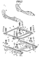
FIG. 2 ] This is an exploded perspective diagram of the passenger's weight measurement device 1. - [
FIG. 3 ] This is a perspective diagram of aload sensor 21. - [
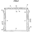
FIG. 4 ] This is a plan diagram of arectangular frame 30. - [
FIG. 5 ] This is a plan diagram of a right front portion of therectangular frame 30. - [
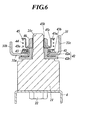
FIG. 6 ] This is a cross-sectional diagram showing a cross section along a line VI-VI ofFIG. 5 . - [
FIG. 7 ] This is a cross-sectional diagram showing a cross section along a line VII-VII ofFIG. 5 . - A best mode for carrying out the present invention will be described below by using the drawings. On embodiments to be described below, a variety of technically preferable limitations are imposed in order to carry out the present invention; however, the scope of the invention is not limited to the following embodiment and illustrated examples.
-
FIG. 1 is a perspective diagram of a passenger's weight measurement device 1 for a vehicle seat, andFIG. 2 is an exploded perspective diagram of the passenger's weight measurement device 1. - As shown in
FIG. 1 andFIG. 2 , aslide adjuster 2 for adjusting a back-and-forth position of the vehicle seat is attached onto a floor of a passenger's room. Theslide adjuster 2 includes a left and right pair oflower rails 3 provided in parallel to each other, a left and right pair ofupper rails 4 engaged with thelower rails 3 so as to be capable of sliding on the respectivelower rails 3 in a rear and front direction with respect to thelower rails 3, alower bracket 5 fixed to lower surfaces of thelower rails 3 by bolt/nut coupling or rivet coupling and bridged between the left and rightlower rails 3, alock mechanism 6 for locking theupper rails 4 to thelower rails 3 and for releasing the locking,brackets 7 attached onto front end portions of the lower surfaces of the respectivelower rails 3, andbrackets 8 attached onto rear end portions of the lower surfaces of the respectivelower rails 3. Thesebrackets lower rails 3 are fixed to the vehicle floor. -
Brackets 9 are fixed to middle positions of upper surfaces of the respectiveupper rails 4 in a rear and front direction by the bolt/nut coupling or the rivet coupling. Thebrackets 9 are provided in a state of being erected with respect to upper surfaces of theupper rails 4. A right end portion of asubmarine pipe 10 is welded to thebrackets 9, and thesubmarine pipe 10 is bridged between the two left andright brackets 9. - A
load sensor 21 is mounted on a front end portion of the upper surface of the rightupper rail 4, and anotherload sensor 21 is mounted on a rear end portion thereof. Also on the upper surface of the leftupper rail 4,load sensors 21 are mounted on a front end portion and rear end portion thereof, respectively. When viewed from the above, these fourload sensors 21 are arranged so as to be apexes of a square or a rectangle. -
FIG. 3 is a perspective diagram of theload sensor 21. All of theload sensors 21 are provided in a similar way. As shown inFIG. 3 , theload sensor 21 includes acolumnar sensing portion 21a that senses a load, a plate-like flange portion 21b extending horizontally in a rear and front direction from a lower end of thesensing portion 21a, arod 21c extending upward from an upper end of thesensing portion 21a, and aconnector 21d extending from thesensing portion 21a so as to be parallel to the flange portion 21b. Therod 21c is formed into a male screw shape. Female screw-shapedcircular holes sensing portion 21a incorporates a strain gauge therein, and the load is converted into an electric signal by the strain gauge. - As shown in
FIG. 2 , theload sensor 21 is fixed to the rightupper rail 4. Specifically, a lower surface of the flange portion 21b abuts on the upper surface of theupper rail 4, and twobolts 22 inserted through theupper rail 4 upward from below are screwed to thecircular holes load sensor 21 is fixed. Note that theload sensor 21 may be fixed to theupper rail 4 by fastening nuts to thebolts 22 on the flange portion 21b without forming any screw threads in thecircular holes - Any
load sensor 21 is fixed to theupper rails 4 as described above. However, with regard to the twoload sensors 21 fixed to the rear portions thereof, theconnectors 21d are directed forward, and with regard to the twoload sensors 21 fixed to the front portions thereof, theconnectors 21d are directed backward. - As shown in
FIG. 1 andFIG. 2 , theframe 30 having a rectangular frame shape is mounted on these fourload sensors 21.FIG. 4 is a top diagram of therectangular frame 30. As shown inFIG. 4 , therectangular frame 30 is composed of a left and right pair ofbeams 31, afront beam 32, and arear cross pipe 33. - Either of the
beams 31 is a metal member having a U-shaped cross section, and has aweb 31a, aninner flange 31b, and anouter flange 31c.Attachment holes 31d are formed in a front portion and a rear portion of theweb 31a, respectively. - The
front beam 32 is a metal member having a U-shaped cross section, and has aweb 32a, afront flange 32b, and arear flange 32c. Thefront beam 32 is bridged between front end portions of the left andright beams 31, and is welded to thesebeams 31. - The
cross pipe 33 is bridged between rear end portions of the left andright beams 31, and is welded to thesebeams 31. - The
rods 21c of theload sensors 21 are inserted into therespective attachment holes 21d upward from below, andnuts 46 are screwed to therods 21c. Therefore, theload sensors 21 are attached onto a right front portion, a right rear portion, a left front portion and a left rear portion of therectangular frame 30, respectively. Referring toFIG. 5 to FIG. 7 , an attachment structure for attaching the rightfront load sensor 21 onto the right front portion of therectangular frame 30 will be described.FIG. 5 is a plan diagram of the right front portion of therectangular frame 30,FIG. 6 is a cross-sectional diagram showing a cross section along a line VI-VI, andFIG. 7 is a cross-sectional diagram showing a cross section along a line VII-VII. As shown inFIG. 5 to FIG. 7 , anannular bush 41 is fitted to an edge of the rightfront attachment hole 31d, and grease is applied on thebush 41. Thebush 41 is made of synthetic resin. Moreover, a steppedcollar 42 composed of acylindrical portion 42a and an annular plate-like flange portion 42b formed on one end surface of thecylindrical portion 42a is inserted through theattachment hole 31d in an inside of thebush 41. Here, thecylindrical portion 42a is inserted through theattachment hole 31d upward from below, and theflange portion 42b engages with a lower surface of theweb 31a via thebush 41. Therefore, the steppedcollar 42 is not pulled out upward. Moreover, thecylindrical portion 42a protrudes from an upper surface of theweb 31a, and an upper end surface of thecylindrical portion 42a is located at a higher position than the upper surface of theweb 31a. Here, thecylindrical portion 42a is fitted to thebush 41, and there is no gap between thecylindrical portion 42a and thebush 41. - The
rod 21c of theload sensor 21 is inserted through the steppedcollar 42 upward from below. An inner diameter of the steppedcollar 42 is designed to be slightly larger than a diameter of therod 21c, and by such designing, a dimension error and an attachment position error are solved. - The
nut 46 is screwed to therod 21c. Aplain washer 43, acoil spring 44 and aspring holder 45 are interposed between the upper surface of theweb 31a of thebeam 31 and thenut 46. Anannular bush 43a is disposed along an edge of a hole of theplain washer 43, and the edge of the hole of theplain washer 43 is sandwiched vertically by this bush. Therefore, thebush 43a is fitted to the edge of the hole of theplain washer 43. In such a way, thebush 43a and theplain washer 43 are integrated with each other. Moreover, thebush 43a protrudes from an upper surface of theplain washer 43. Therefore, astep difference 43b is formed on the upper surface of theplain washer 43 by thebush 43a. Moreover, a lower surface of theplain washer 43 and a lower surface of thebush 43a become flush with each other. Furthermore, therod 21c is inserted through thecoil spring 44, thecoil spring 44 is set in a state of being mounted on theplain washer 43 on a circumference of thebush 43a, and an end portion of thecoil spring 44 engages with thestep difference 43b formed by thebush 43a. Therefore, thecoil spring 44 is centered with respect to theplain washer 43. A portion of thecoil spring 44, which is brought into contact with theplain washer 43, is formed to be flat. Thebush 43a is made of synthetic resin, and a tapping sound is prevented by thebush 43a. - The
spring holder 45 includes acup portion 45c in which a through hole is formed in a bottom 45b, and anannular flange 45a formed on an outer circumferential surface in an opening of thecup portion 45c. Then, therod 21c penetrates through the through hole of the bottom 45b of thecup portion 45c, the bottom 45b of thecup portion 45c is set in a state of being mounted on an end surface of the steppedcollar 42, and thecup portion 45c is inserted into thecoil spring 44. Moreover, thecoil spring 44 and theplain washer 43 are set in a state of being sandwiched between theflange 45a of thespring holder 45 and theweb 31a. - The
nut 46 is screwed to therod 21c in a state of being inserted into thecup portion 45c, and by tightening thenut 46, the bottom 45b of thecup portion 45c is sandwiched between thenut 46 and the upper end surface of thecylindrical portion 42a, and thecoil spring 44 and theplain washer 43 are sandwiched between theflange 45a and theweb 31a of thebeam 31. Moreover, since thecoil spring 44 is compressed by tightening thenut 46, the load is applied to thenut 46, and accordingly, thenut 46 is prevented from being loosened. - Like the right
front load sensor 21, the left front, left rear and rightrear load sensors 21 are attached onto the left front, left rear and rightrear attachment holes 31d, respectively. In a state where the fourload sensors 21 are attached onto therectangular frame 30, thesubmarine pipe 10 is located behind thefront beam 32. - As shown in
FIG. 1 andFIG. 2 , side frames 51 are welded to theouter flanges 31c of the left andright beams 31, respectively. These side frames 51 are parts of a bottom frame of the vehicle seat. - From above, front portions of the side frames 51 are covered with a
pan frame 53, and the side frames 51 and thepan frame 53 are fixed to each other by the bolt/nut coupling or the rivet coupling. Aseat spring 54 is bridged between thecross pipe 33 and thepan frame 53, a cushion is mounted on thepan frame 53 and theseat spring 54, and the cushion, thepan frame 53 and the side frames 51 are entirely covered with a cover. - A backrest frame is coupled to rear ends of the side frames 51, and is capable of rising and falling by a reclining mechanism. Note that the backrest frame and the cushion are not shown in order to make it easy to view the drawings.
- In the passenger's weight measurement device 1 configured as described above, when a passenger is seated on a seat bottom, a weight of the passenger is applied to the four
load sensors 21 through therectangular frame 30, and is converted into electric signals by theseload sensors 21. - Here, the
load sensors 21 are attached between theupper rails 4 and therectangular frame 30, and theload sensors 21 move in a rear and front direction integrally with the vehicle seat. Accordingly, a load inputted from the vehicle seat to theload sensors 21 can be always kept constant irrespective of position of the vehicle seat in a rear and front direction. Therefore, measuring accuracy of the passenger's weight can be enhanced. - Moreover, the
spring holder 45 is mounted on the upper end surface of the steppedcollar 42, and thecoil spring 44 is sandwiched between thespring holder 45 and theweb 31a by tightening thenut 46. Accordingly, therectangular frame 30 can be shifted in the vertical direction with respect to theload sensors 21. Therefore, noise of the load generated by distortion of theslide adjuster 2 and the like becomes smaller. - Moreover, even if the
rectangular frame 30 can be shifted in the vertical direction with respect to theload sensors 21, the coil springs 44 are interposed between the nuts 46 and thewebs 31a, and accordingly, theload sensors 21 can be fixed to therectangular frame 30 more stably and appropriately. Therefore, it becomes easier to assemble the passenger's weight measurement device 1. - Moreover, the load is stably applied from each of the coil springs 44 to each of the nuts 46 owing to elastic deformation of the
coil spring 44, which is caused by tightening thenut 46. - Moreover, the
submarine pipe 10 is located behind thefront beam 32, and accordingly, when forward inertial force is applied to the passenger owing to a frontal collision or the like of the vehicle, buttocks of the passenger seated on the vehicle seat are restrained by thesubmarine pipe 10. Therefore, a so-called submarine phenomenon in which the passenger moves under a waist belt can be prevented. - Note that the present invention is not limited to the above-described embodiment, and various improvements and design changes can be made within the scope without departing from the gist of the present invention.
- As described above, the present invention can be widely used, for example, for seats of an automobile, an electric train and other vehicles.
-
- 1. A passenger's weight measurement device for a vehicle seat, comprising;
an upper rail provided on a lower rail fixed to a vehicle floor so as to be movable in a rear and front direction;
a load sensor fixed onto the upper rail; and
a frame provided on the load sensor and below the vehicle seat,
wherein a rod is extended from the load sensor, and the rod sequentially penetrates the frame, a plain washer and a spring holder, and is inserted into a coil spring,
a bush is disposed along an edge of a hole of the plain washer, through which the rod is inserted, and a step difference is formed between an upper surface of the plain washer and the bush by protruding the bush from the upper surface, and
a nut is screwed to the rod from above the spring holder, and the coil spring is sandwiched between the spring holder and the frame and is compressed and an end portion of the coil spring engages with the step difference by tightening the nut to the spring holder. - 2. A passenger's weight measurement device according to paragraph 1, wherein the frame is configured to be shifted in vertical direction with respect to the load sensor.
- 3. A passenger's weight measurement device according to
paragraph 2, wherein the device is configured to prevent assembling distortions of the upper rail, lower rail and the frame from being applied to the load sensor. - 4. A passenger's weight measurement device according to paragraph 1, wherein the device is configured to stably fix the load sensor to the frame by the coil spring being sandwiched, in compression, between the frame and the spring holder.
- 5. A passenger's weight measurement device according to paragraph 1, wherein the device is configured to stably apply the load from the coil to the nut, the load provided by the elastic deformation of the coil spring, the elastic deformation provided by tightening the nut.
- 6. A passenger's weight measurement device according to paragraph 1, wherein the device is configured such that an end portion of the coil spring engages with the step difference to center the coil spring with respect to the washer without slipping on the upper surface of the washer.
- 7. A passenger weight measurement device (1) for a vehicle seat, comprising:
- an upper rail (4) provided on a lower rail (3) fixed to a vehicle floor so as to be movable in a rear and front direction;
- a load sensor (21) fixed onto the upper rail (4) and
- a frame (30) provided on the load sensor (21) and below the vehicle seat;
wherein - an attachment hole (31d) is formed in the frame (30), and an annular bush (41) is fitted to an edge of the attachment hole (31 d),
- a stepped collar (42), composed of a cylindrical portion (42a) and an annular plate-like flange portion (42b) formed on one end surface of the cylindrical portion (42a), is inserted through the attachment hole (31d) in an inside of the annular bush (41) such that the flange portion (42b) engages with a lower surface of the frame (30) via the annular bush (41),
- a rod (21 c) of the load sensor (21) is inserted through the stepped collar (42),
and - a nut (46) is screwed to the rod (21c).
- 8. The passenger weight measurement device (1) of
paragraph 7, wherein the cylindrical portion (42a) is fitted to the annular bush (41) such that there is no gap between the cylindrical portion (42a) and the bush (41). - 9. The passenger weight measurement device (1) of
paragraph - 10. The passenger weight measurement device (1) of
paragraph 9, wherein the cup portion (45c) of the spring holder (45) comprises a cylindrical edge, and wherein the coil spring (44) is positioned around the cylindrical edge of the cup portion (45c). - 11. The passenger weight measurement device (1) of
paragraph 10, wherein the cylindrical edge of the cup portion (45c) extends in a direction parallel to the axis of the rod. (21 c). - 12. The passenger weight measurement device (1) of any of
paragraphs 9 to 11, wherein one end (45b) of the cup portion (45c) comprises a hole through which the rod (21 c) penetrates, and the other end of the cup portion (45c) is open. - 13. The passenger weight measurement device (1) of any preceding paragraph wherein a side frame (51) contacts to an outer flange (31c) of the frame having the attachment hole (31 d), a front portion of the side frame (51) is covered with a pan frame (53) from above, and the pan frame (53) is fixed to the side frame (51).
- 14. The passenger weight measurement device (1) of any preceding paragraph, wherein the frame (30) comprises left and right beams (31) connected by an adjoining beam (32), the left and right beams (31) each having a U-shaped cross-section comprising inner (31b) and outer (31c) flanges connected by a web (31a), the attachment hole (31d) formed in the web (31a), and wherein the rod (21c) is inserted through the attachment hole (31 d) between the inner (31 b) and outer (31 c) flanges.
- 15. The passenger weight measurement device (1) of paragraph 14, wherein the left and right beams (31) each comprise an attachment hole (31d), and wherein the width of the web (31 a) is greatest at the attachment hole (31 d).
- 16. The passenger weight measurement device (1) of any preceding paragraph, wherein the upper (4) and lower (3) rails each comprise a pair of left and right rails, the left and right rails of the lower rail (3) connected to one another by a bracket (5), and wherein the left and right rails of each pair (3, 4) each comprise a plurality of holes.
- 17. A method of assembling a passenger's weight measurement device (1) for a vehicle seat, the method comprising:
- providing an upper rail (4) on a lower rail (3) fixed to a vehicle floor so as to be movable in a front and rear direction;
- fixing a load sensor (21) onto the upper rail (4);
- providing a frame (30) on the load sensor (21) and below the vehicle seat;
- forming an attachment hole (31d) in the frame (30);
- fitting an annular bush (41) to an edge of the attachment hole (31 d);
- providing a stepped collar (42) composed of a cylindrical portion (42a) and an annular plate-like flange portion (42b) formed on one end surface of the cylindrical portion (42a);
- inserting the stepped collar (42) through the attachment hole (31d) in an inside of the annular bush (41) such that the flange portion (42b) engages with a lower surface of the frame (30) via the annular bush (41);
- inserting a rod (21 c) of the load sensor (21) through the stepped collar (42); and
- screwing a nut (46) to the rod (21 c).
- 18. The method of paragraph 17, wherein the method comprises fitting the cylindrical portion (42a) to the annular bush (41) such that there is no gap between the cylindrical portion (42a) and the annular bush (41).
- 19. The method of paragraph 17 or 18, wherein the method comprises inserting the rod (21c) through the frame (30) and into a spring holder (45) and a coil spring (44), the spring holder (45) comprising a cup portion (45c) for receiving a nut (46), and an annular flange (45a), the method further comprising inserting the nut (46) into the cup portion (45c) of the spring holder (45), screwing the nut (46) to the rod (21 c) such that the coil spring (44) is sandwiched between the frame (30) and the annular flange (45a) of the spring holder (45), and tightening the nut (46) to compress the coil spring (44).
- 20. The method of paragraph 19, wherein the cup portion (45c) of the spring holder (45) comprises a cylindrical edge, the method comprising positioning the coil spring (44) around the cylindrical edge of the cup portion (45c).
- 21. The method of paragraph 20, wherein the cylindrical edge of the cup portion (45c) extends in a direction parallel to the axis of the rod (21 c).
Claims (14)
- A passenger weight measurement device (1) for a vehicle seat, comprising:an upper rail (4) provided on a lower rail (3) fixed to a vehicle floor so as to be movable in a rear and front direction;a load sensor (21) fixed to the upper rail (4); anda frame (30) attached to the load sensor (21) and provided at the vehicle seat; whereinan attachment hole (31d) is formed in the frame (30), and an annular bush (41) is fitted to an edge of the attachment hole (31d),a stepped collar (42), composed of a cylindrical portion (42a) and an annular plate-like flange portion (42b) formed on one end surface of the cylindrical portion (42a), is inserted through the attachment hole (31d) in an inside of the annular bush (41) such that the flange portion (42b) engages with the frame (30) via the annular bush (41) and the cylindrical portion (42a) is fitted to the bush (41) having no gap therebetween,a rod (21c) of the load sensor (21) is inserted through the stepped collar (42), anda nut (46) is screwed to the rod (21c).
- The passenger weight measurement device (1) of claim 1, wherein the annular flange-like portion (42b) is fitted to the annular bush (41) such that there is no gap between the flange portion (42a) and the bush (41).
- The passenger weight measurement device (1) of claim 1 or 2, wherein the rod (21c) extends from the load sensor (21) penetrating the frame (30), and wherein a nut (46) is screwed to the rod (21c).
- The passenger weight measurement device (1) of any preceding claim, wherein a side frame (51) contacts to an outer flange (31c) of the frame having the attachment hole (31d), a front portion of the side frame (51) is covered with a pan frame (53), and the pan frame (53) is fixed to the side frame (51).
- The passenger weight measurement device (1) of any preceding claim, wherein the frame (30) comprises left and right beams (31) connected by an adjoining beam (32), the left and right beams (31) each having a U-shaped cross-section comprising inner (31b) and outer (31 c) flanges connected by a web (31 a), the attachment hole (31 d) formed in the web (31 a), and wherein the rod (21 c) is inserted through the attachment hole (31 d) between the inner (31 b) and outer (31 c) flanges.
- The passenger weight measurement device (1) of claim 5, wherein the left and right beams (31) each comprise an attachment hole (31d), and wherein the width of the web (31 a) is greatest at the attachment hole (31 d).
- The passenger weight measurement device (1) of any preceding claim, wherein the upper (4) and lower (3) rails each comprise a pair of left and right rails, the left and right rails of the lower rail (3) connected to one another by a bracket (5), and wherein the left and right rails of each pair (3, 4) each comprise a plurality of holes.
- A method of assembling a passenger's weight measurement device (1) for a vehicle seat, the method comprising:providing an upper rail (4) on a lower rail (3) fixed to a vehicle floor so as to be movable in a front and rear direction;fixing a load sensor (21) to the upper rail (4);attaching a frame (30) to the load sensor (21) at the vehicle seat;forming an attachment hole (31d) in the frame (30);fitting an annular bush (41) to an edge of the attachment hole (31d);providing a stepped collar (42) composed of a cylindrical portion (42a) and an annular plate-like flange portion (42b) formed on one end surface of the cylindrical portion (42a);inserting the stepped collar (42) through the attachment hole (31d) in an inside of the annular bush (41) such that the flange portion (42b) engages with the frame (30) via the annular bush (41) and the cylindrical portion (42a) is fitted to the bush (41) having no gap therebetween;inserting a rod (21c) of the load sensor (21) through the stepped collar (42); andscrewing a nut (46) to the rod (21 c).
- The method of claim 8, wherein the method comprises fitting the annular flange-like (42b) to the annular bush (41) such that there is no gap between the flange portion (42a) and the annular bush (41).
- The method of claim 8 or 9, wherein the method comprises inserting the rod (21 c) through the frame (30), and screwing a nut (46) to the rod (21 c).
- The method of any of claims 8 to 10, wherein the method comprises contacting a side frame (51) to an outer flange (31c) of the frame (30) having the attachment hole (31 d); covering a front portion of the side frame (51) with a pan frame (53); and fixing the pan frame (53) to the side frame (51).
- The method of any of claims 8 to 11, wherein the method comprises connecting left and right beams (31) of the frame (30) by an adjoining beam (32), the left and right beams (31) each having a U-shaped cross-section comprising inner (31 b) and outer (31 c) flanges connected by a web (31 a), the attachment hole (31 d) formed in the web (31a); and inserting the rod (21c) through the attachment hole (31d) between the inner (31 b) and outer (31 c) flanges.
- The method of claim 12, wherein the left and right beams (31) each comprise an attachment hole (31d), and wherein the width of the web (31 a) is greatest at the attachment hole (31d).
- The method of any of claims 8 to 13, wherein the upper (4) and lower (3) rails each comprise a pair of left and right rails, the left and right rails of each pair (3, 4) comprising a plurality of holes, and wherein the method comprises connecting the left and right rails of the lower rail (3) to one another by a bracket (5).
Applications Claiming Priority (3)
| Application Number | Priority Date | Filing Date | Title |
|---|---|---|---|
| JP2005286881 | 2005-09-30 | ||
| EP06810877A EP1946960B1 (en) | 2005-09-30 | 2006-09-29 | Occupant weight measurement device for vehicle seat |
| EP10007613A EP2241477A1 (en) | 2005-09-30 | 2006-09-29 | Passenger's weight measurement device for vehicle seat |
Related Parent Applications (2)
| Application Number | Title | Priority Date | Filing Date |
|---|---|---|---|
| EP06810877.8 Division | 2006-09-29 | ||
| EP10007613.2 Division | 2010-07-22 |
Publications (1)
| Publication Number | Publication Date |
|---|---|
| EP2407342A1 true EP2407342A1 (en) | 2012-01-18 |
Family
ID=37899795
Family Applications (4)
| Application Number | Title | Priority Date | Filing Date |
|---|---|---|---|
| EP06810877A Expired - Fee Related EP1946960B1 (en) | 2005-09-30 | 2006-09-29 | Occupant weight measurement device for vehicle seat |
| EP10007613A Withdrawn EP2241477A1 (en) | 2005-09-30 | 2006-09-29 | Passenger's weight measurement device for vehicle seat |
| EP06810875A Expired - Fee Related EP1930209B1 (en) | 2005-09-30 | 2006-09-29 | Occupant weight measurement device for vehicle seat and installation structure for load sensor |
| EP11181454A Withdrawn EP2407342A1 (en) | 2005-09-30 | 2006-09-29 | Passenger's weight measurement device for vehicle seat |
Family Applications Before (3)
| Application Number | Title | Priority Date | Filing Date |
|---|---|---|---|
| EP06810877A Expired - Fee Related EP1946960B1 (en) | 2005-09-30 | 2006-09-29 | Occupant weight measurement device for vehicle seat |
| EP10007613A Withdrawn EP2241477A1 (en) | 2005-09-30 | 2006-09-29 | Passenger's weight measurement device for vehicle seat |
| EP06810875A Expired - Fee Related EP1930209B1 (en) | 2005-09-30 | 2006-09-29 | Occupant weight measurement device for vehicle seat and installation structure for load sensor |
Country Status (6)
| Country | Link |
|---|---|
| US (12) | US8051941B2 (en) |
| EP (4) | EP1946960B1 (en) |
| JP (2) | JP4949257B2 (en) |
| CN (3) | CN102009630B (en) |
| DE (2) | DE602006014705D1 (en) |
| WO (2) | WO2007037374A1 (en) |
Families Citing this family (42)
| Publication number | Priority date | Publication date | Assignee | Title |
|---|---|---|---|---|
| JP4695358B2 (en) | 2004-07-30 | 2011-06-08 | テイ・エス テック株式会社 | Vehicle seat occupant weight measurement device |
| JP4050729B2 (en) * | 2004-07-30 | 2008-02-20 | テイ・エス テック株式会社 | Vehicle seat occupant weight measurement device |
| ITBO20050244A1 (en) * | 2005-04-15 | 2006-10-16 | Ferrari Spa | ASSEMBLY SYSTEM WITH OCCUPANT WEIGHT MEASUREMENT FOR A SEAT OF A MOTOR VEHICLE |
| US7455343B2 (en) * | 2005-09-12 | 2008-11-25 | Ts Tech Co., Ltd. | Passenger's weight measurement device for vehicle seat and attachment structure for load sensor |
| EP1946960B1 (en) | 2005-09-30 | 2010-09-08 | TS Tech Co., Ltd. | Occupant weight measurement device for vehicle seat |
| JP5318105B2 (en) * | 2007-09-10 | 2013-10-16 | ジョンソン コントロールズ テクノロジー カンパニー | Enhancement of vehicle seat power truck |
| JP5064973B2 (en) * | 2007-11-02 | 2012-10-31 | 株式会社イシダ | Weight inspection device |
| KR101430195B1 (en) * | 2008-08-18 | 2014-08-18 | 현대모비스 주식회사 | Apparatus for differentiating passengers |
| KR101430196B1 (en) * | 2008-08-18 | 2014-08-18 | 현대모비스 주식회사 | Apparatus for differentiating passengers |
| JP2010139364A (en) * | 2008-12-11 | 2010-06-24 | Calsonic Kansei Corp | Load sensor for vehicle seat |
| KR101181083B1 (en) * | 2009-11-20 | 2012-09-07 | 현대모비스 주식회사 | Weight sensor of weight classification system |
| CN103025576B (en) * | 2010-06-22 | 2015-04-29 | 丰田纺织株式会社 | Vehicle seat mounting structure |
| US9151644B2 (en) * | 2011-07-28 | 2015-10-06 | Ts Tech Co., Ltd. | Load measurement sensor support structure |
| WO2013022063A1 (en) * | 2011-08-10 | 2013-02-14 | テイ・エス テック株式会社 | Support structure for load measurement sensor |
| JP5777250B2 (en) * | 2011-11-04 | 2015-09-09 | 株式会社エー・アンド・デイ | Meter |
| JP5959361B2 (en) * | 2012-07-31 | 2016-08-02 | テイ・エス テック株式会社 | Vehicle seat |
| WO2014084036A1 (en) | 2012-11-30 | 2014-06-05 | テイ・エス テック株式会社 | Seat for vehicle |
| US9400207B2 (en) * | 2013-03-15 | 2016-07-26 | Illinois Tool Works Inc. | Sensor mounting bracket |
| WO2014167639A1 (en) * | 2013-04-08 | 2014-10-16 | テイ・エス テック株式会社 | Seat frame |
| US10017078B2 (en) | 2013-05-30 | 2018-07-10 | Yefim G Kriger | Relocatable/replaceable pad for accurate vehicle occupant weight measurement |
| JP5587477B1 (en) * | 2013-09-10 | 2014-09-10 | 株式会社フジクラ | Seat device |
| JP6200818B2 (en) * | 2014-01-21 | 2017-09-20 | ルネサスエレクトロニクス株式会社 | Manufacturing method of semiconductor device |
| US9227526B2 (en) * | 2014-02-27 | 2016-01-05 | Delphi Technologies, Inc. | Occupant detection device with temperature compensation |
| DE102014214926A1 (en) | 2014-07-30 | 2016-02-04 | Bayerische Motoren Werke Aktiengesellschaft | Motor vehicle with a device for checking the payload and method for checking the payload |
| KR101617801B1 (en) * | 2014-10-16 | 2016-05-03 | 현대모비스 주식회사 | Passenger Identification Device |
| US9891130B2 (en) * | 2015-06-09 | 2018-02-13 | Ford Global Technologies, Llc | System and method for testing seat pressure sensor |
| US10059226B2 (en) * | 2015-10-23 | 2018-08-28 | Ts Tech Co., Ltd. | Vehicle seat |
| LU93159B1 (en) * | 2016-07-22 | 2018-01-23 | Iee Sa | Sensor carrier to carry one or more sensor elements and cabeling |
| EP3379222B1 (en) | 2017-03-22 | 2020-12-30 | Methode Electronics Malta Ltd. | Magnetoelastic based sensor assembly |
| JP6809375B2 (en) * | 2017-05-22 | 2021-01-06 | トヨタ紡織株式会社 | Fastening structure for vehicle seats and fasteners for vehicle seats |
| JP6356882B1 (en) * | 2017-07-31 | 2018-07-11 | テイ・エス テック株式会社 | Sensor arrangement structure on the seat |
| JP6826964B2 (en) * | 2017-08-28 | 2021-02-10 | 株式会社タチエス | Vehicle seat |
| US11491832B2 (en) | 2018-02-27 | 2022-11-08 | Methode Electronics, Inc. | Towing systems and methods using magnetic field sensing |
| US11084342B2 (en) | 2018-02-27 | 2021-08-10 | Methode Electronics, Inc. | Towing systems and methods using magnetic field sensing |
| US11135882B2 (en) | 2018-02-27 | 2021-10-05 | Methode Electronics, Inc. | Towing systems and methods using magnetic field sensing |
| US11014417B2 (en) | 2018-02-27 | 2021-05-25 | Methode Electronics, Inc. | Towing systems and methods using magnetic field sensing |
| EP3758959A4 (en) | 2018-02-27 | 2022-03-09 | Methode Electronics, Inc. | Towing systems and methods using magnetic field sensing |
| US11221262B2 (en) | 2018-02-27 | 2022-01-11 | Methode Electronics, Inc. | Towing systems and methods using magnetic field sensing |
| JP7391873B2 (en) * | 2018-04-19 | 2023-12-05 | フィッシャー ダイナミクス ジャーマニー ゲーエムベーハ― | Automotive drive unit with electric motor, transmission and spindle |
| FR3081399B1 (en) * | 2018-05-25 | 2021-01-08 | Faurecia Sieges Dautomobile | MOTOR VEHICLE SEAT |
| US10744981B2 (en) * | 2018-06-06 | 2020-08-18 | Sensata Technologies, Inc. | Electromechanical braking connector |
| US20220313882A1 (en) * | 2021-04-05 | 2022-10-06 | Simergent Llc | Automated peritoneal dialysis device |
Citations (5)
| Publication number | Priority date | Publication date | Assignee | Title |
|---|---|---|---|---|
| JPH08164039A (en) | 1994-12-14 | 1996-06-25 | Nissan Motor Co Ltd | Condition adjusting method for vehicle seat and condition adjusting device for vehicle seat |
| JPH09207638A (en) | 1996-02-07 | 1997-08-12 | Nippon Soken Inc | Crew detector |
| DE10315400A1 (en) * | 2003-04-04 | 2004-10-14 | Volkswagen Ag | Vehicle seat load detection sensor has magnetic stator element attached to seat or attachment structure, coil element attached to seat or attachment structure, relatively movable under weight loading |
| US20050061643A1 (en) * | 2003-09-22 | 2005-03-24 | Rainey Robert R. | Vehicle seat weight sensor |
| GB2415787A (en) * | 2004-07-02 | 2006-01-04 | Lear Corp | Vehicle seat assembly with occupant sensor system |
Family Cites Families (140)
| Publication number | Priority date | Publication date | Assignee | Title |
|---|---|---|---|---|
| US635620A (en) * | 1899-05-01 | 1899-10-24 | Julius Wm Walters | Motor-wheel for vehicles. |
| US1679620A (en) | 1926-10-04 | 1928-08-07 | Thomas M Moore | Yielding fastener |
| US2252970A (en) | 1940-12-19 | 1941-08-19 | Stanley J Gedris | Chair back construction |
| US2589922A (en) * | 1949-03-01 | 1952-03-18 | Harry A Bowman | Quick detachable anchoring means for chairs and the like |
| US2589570A (en) | 1950-03-28 | 1952-03-18 | Robert L Welch Jr | Mechanical amusement or exercising horse |
| US4178037A (en) | 1975-02-26 | 1979-12-11 | Ferro Manufacturing Corporation | Seat recliner assembly |
| US4182255A (en) | 1978-02-22 | 1980-01-08 | Reid Bruce D | Below waterline deployable hull stabilizing members |
| US4209198A (en) | 1978-09-15 | 1980-06-24 | Metafab Industries, Inc. | Knockdown chair |
| US4281443A (en) | 1979-07-27 | 1981-08-04 | James Threlfall | Position maintaining tool |
| US4353565A (en) | 1980-12-18 | 1982-10-12 | Smith Gary L | Attachment for automotive trailers |
| US4509796A (en) | 1981-12-29 | 1985-04-09 | Tachikawa Spring Co., Ltd. | Seat frame for vehicle seat |
| GB8331260D0 (en) * | 1983-11-23 | 1983-12-29 | Toll I C | Aircraft seats |
| AU563843B2 (en) | 1984-03-23 | 1987-07-23 | Tachikawa Spring Co. Ltd. | Sliding seat adjuster |
| US4588225A (en) * | 1984-03-30 | 1986-05-13 | Tachikawa Spring Co., Ltd. | Height adjustment mechanism for a vehicle seat |
| JPS6274397A (en) | 1985-09-30 | 1987-04-06 | アイシン精機株式会社 | Apparatus for mounting seat cover for car |
| JPS6326466A (en) | 1986-07-16 | 1988-02-04 | Kyushu Denshi Kinzoku Kk | Seal device for rotary machine |
| JPH042113Y2 (en) | 1986-08-06 | 1992-01-24 | ||
| JPH0353384U (en) | 1989-09-30 | 1991-05-23 | ||
| US5240310A (en) | 1989-11-30 | 1993-08-31 | Bayer Aktiengesellschaft | Seat base for vehicle seats |
| US5222399A (en) | 1991-02-01 | 1993-06-29 | Fel-Pro Incorporated | Load washer |
| JP2534247Y2 (en) | 1991-07-02 | 1997-04-30 | 株式会社ユニシアジェックス | Load sensor mounting structure |
| JPH0543031A (en) | 1991-08-14 | 1993-02-23 | Matsushita Electric Works Ltd | Screw conveyor |
| GB9203227D0 (en) * | 1992-02-14 | 1992-04-01 | Gec Avery Technology | Improvements in or relating to force sensors |
| US6242701B1 (en) | 1995-06-07 | 2001-06-05 | Automotive Technologies International, Inc. | Apparatus and method for measuring weight of an occupying item of a seat |
| US5308148A (en) | 1992-09-24 | 1994-05-03 | Indiana Mills And Manufacturing, Inc. | Seat belt module assembly |
| US5286076A (en) | 1992-11-24 | 1994-02-15 | Douglas & Lomason Company | Seat slide device |
| JP2864925B2 (en) | 1992-12-28 | 1999-03-08 | 日産自動車株式会社 | Mounting structure of steering member |
| US5600104A (en) * | 1993-10-20 | 1997-02-04 | Structural Instrumentation, Inc. | Load cell having reduced sensitivity to non-symmetrical beam loading |
| US5421124A (en) | 1994-08-22 | 1995-06-06 | General Motors Corporation | Adjustable vehicle door wedge |
| US6010195A (en) | 1995-11-27 | 2000-01-04 | Lear Corporation | Automotive modular seat frame assembly |
| DE19625821C1 (en) * | 1996-06-28 | 1997-12-18 | Johannes Borngaesser | Stand for a measuring cell |
| US5991676A (en) * | 1996-11-22 | 1999-11-23 | Breed Automotive Technology, Inc. | Seat occupant sensing system |
| US5714695A (en) | 1997-02-04 | 1998-02-03 | Sentek Products | Helical load cell |
| JP3353645B2 (en) | 1997-04-24 | 2002-12-03 | トヨタ自動車株式会社 | Occupant weight detection device |
| US6089478A (en) | 1997-05-22 | 2000-07-18 | Trynex, Inc. | Spreader assembly |
| US5775780A (en) | 1997-07-28 | 1998-07-07 | General Motors Corporation | Auxiliary vehicle seat support rail with dynamic seat belt and seat back anchoring |
| US5921624A (en) | 1997-09-23 | 1999-07-13 | Wu; Chin-Chang | Seat assembly for a bicycle |
| JPH11108746A (en) | 1997-10-07 | 1999-04-23 | Kansei Corp | Vehicle occupant detection device |
| JP3376887B2 (en) | 1997-10-13 | 2003-02-10 | トヨタ自動車株式会社 | Vehicle seat |
| US5942695A (en) | 1997-12-22 | 1999-08-24 | Delco Electronics Corp | Method and apparatus for measuring seat loading by strain gauge |
| FR2772690B1 (en) | 1997-12-24 | 2000-02-18 | Faure Bertrand Equipements Sa | SEAT OF A MOTOR VEHICLE SEAT COMPRISING AN ANTI-SUBMARINE CROSSING |
| US6039344A (en) | 1998-01-09 | 2000-03-21 | Trw Inc. | Vehicle occupant weight sensor apparatus |
| JP3655745B2 (en) | 1998-04-16 | 2005-06-02 | タカタ株式会社 | Seat weight measuring device |
| US20050067828A1 (en) * | 1998-05-19 | 2005-03-31 | Peter Norton | Load cell and seat occupant weight sensing system |
| EP1020320B1 (en) | 1999-01-14 | 2007-08-01 | Toyota Jidosha Kabushiki Kaisha | Sitting passenger detecting apparatus and sitting passenger detecting method |
| JP3633414B2 (en) | 1999-02-19 | 2005-03-30 | トヨタ自動車株式会社 | Seated occupant detection device |
| US6145909A (en) | 1999-02-02 | 2000-11-14 | Asc Incorporated | Automotive vehicle bootwell and drain trough apparatus |
| US6557424B1 (en) * | 1999-02-24 | 2003-05-06 | Siemens Vdo Automotive Corporation | Method and apparatus for sensing seat occupant weight |
| JP2000280813A (en) | 1999-03-30 | 2000-10-10 | Toyota Motor Corp | Seated occupant detection device |
| JP3498177B2 (en) | 1999-07-16 | 2004-02-16 | テイ・エス テック株式会社 | Wiring structure of harness in seat |
| US6405987B1 (en) | 1999-08-05 | 2002-06-18 | Dura Global Technologies, Inc. | Reinforcement member for a seat mounting assembly |
| JP2001050329A (en) | 1999-08-06 | 2001-02-23 | Toyoda Gosei Co Ltd | Cap for shock absorber |
| DE19949728B8 (en) | 1999-10-15 | 2005-06-30 | Daimlerchrysler Ag | Vehicle seat with towing hitch |
| US6231076B1 (en) | 1999-11-16 | 2001-05-15 | Cts Corporation | Automobile seat having seat supporting brackets with a stepped weight sensor |
| TW511409B (en) * | 2000-05-16 | 2002-11-21 | Hitachi Aic Inc | Printed wiring board having cavity for mounting electronic parts therein and method for manufacturing thereof |
| WO2002017753A1 (en) | 2000-08-31 | 2002-03-07 | Ts Tech Co., Ltd. | Vehicle seat |
| JP3694450B2 (en) * | 2000-09-18 | 2005-09-14 | アルプス電気株式会社 | Load sensor |
| JP2002144936A (en) | 2000-11-08 | 2002-05-22 | Nhk Spring Co Ltd | Sitting sensing device for automobile seat |
| US6595570B2 (en) * | 2000-11-22 | 2003-07-22 | Lear Corporation | Vehicle seat assembly having load cell based seat occupant sensing system |
| JP2002166768A (en) | 2000-11-30 | 2002-06-11 | Tachi S Co Ltd | Load detecting structure of vehicle seat |
| JP2002168682A (en) | 2000-11-30 | 2002-06-14 | Tachi S Co Ltd | Load detecting structure of slide seat for vehicle |
| JP2002174556A (en) | 2000-12-08 | 2002-06-21 | Mitsubishi Electric Corp | Crew-detecting device |
| US6616239B2 (en) | 2001-04-18 | 2003-09-09 | Hickory Springs Manufacturing Company | Rail clip for seat bases |
| JP2002333366A (en) | 2001-05-08 | 2002-11-22 | Aisin Seiki Co Ltd | Crew judging device |
| US6499360B1 (en) | 2001-05-22 | 2002-12-31 | Gagetek Technologies Holdings Company | Torsional sensing load cell with overload protection |
| US6644903B1 (en) | 2001-06-12 | 2003-11-11 | Matdan America Corp. | Captive fastener with gradient hardened ferrule |
| US6555765B2 (en) * | 2001-06-12 | 2003-04-29 | Alan Paine | Method and apparatus for determining the weight of the contents of a vessel |
| JP2003011709A (en) * | 2001-07-03 | 2003-01-15 | Delta Kogyo Co Ltd | Seating detector of seat |
| CN1265178C (en) | 2001-07-31 | 2006-07-19 | 古河电气工业株式会社 | Weight sensing device |
| KR100456555B1 (en) * | 2001-08-14 | 2004-11-10 | 현대자동차주식회사 | Pannel structure to prevent submarine for automobile |
| JP4669175B2 (en) | 2001-09-13 | 2011-04-13 | アイシン精機株式会社 | Seat load sensor mounting structure for vehicle seat |
| US6559392B1 (en) | 2001-10-12 | 2003-05-06 | Lear Corporation | Weight-sensing support assembly for automotive seat cushion frame |
| JP2005510394A (en) * | 2001-10-31 | 2005-04-21 | オートモーティブ システムズ ラボラトリー インコーポレーテッド | Occupant detection system |
| KR100442746B1 (en) | 2001-11-08 | 2004-08-02 | 주식회사다스 | Locking system of seat rail for vehicle |
| US6682146B2 (en) * | 2001-11-28 | 2004-01-27 | Taichi-S Co., Ltd. | Structure of seat cushion frame in vehicle seat |
| JP2003227702A (en) | 2001-11-28 | 2003-08-15 | Aisin Seiki Co Ltd | Seat position detector |
| JP2003166872A (en) | 2001-12-04 | 2003-06-13 | Tachi S Co Ltd | Load detection structure of vehicle seat |
| US6916997B2 (en) | 2001-12-07 | 2005-07-12 | Robert Bosch Corporation | Weight sensors having centralized loose tolerance universal force and Mx/My moments overload stops |
| JP3917874B2 (en) | 2002-02-12 | 2007-05-23 | アイシン精機株式会社 | Crew determination device |
| JP2003287458A (en) | 2002-03-27 | 2003-10-10 | Aisin Seiki Co Ltd | Sitting-load detector |
| US6786691B2 (en) | 2002-05-07 | 2004-09-07 | Tyco Electronics Corporation | Load cell for securing electronic components |
| US6637824B1 (en) | 2002-05-30 | 2003-10-28 | Tachi-S Co., Ltd. | Arrangement for securing support springs in vehicle seat frame |
| DE60314059T2 (en) | 2002-07-29 | 2008-01-24 | The Furukawa Electric Co., Ltd. | Vehicle seat with built-in occupant sensor |
| US20040032117A1 (en) | 2002-08-19 | 2004-02-19 | Pinto Nicholas W. | Seat back load sensor |
| JP3818242B2 (en) * | 2002-08-26 | 2006-09-06 | 松下電器産業株式会社 | Mounting device for weight measuring device |
| JP4189463B2 (en) | 2003-01-06 | 2008-12-03 | テイ・エス テック株式会社 | Automotive seat with position sensor |
| DE60336673D1 (en) | 2002-11-12 | 2011-05-19 | Ts Tech Co Ltd | LEVEL SENSOR SYSTEM AND ACCORDING SHIPPING VEHICLE SEAT |
| US7185867B2 (en) | 2002-11-15 | 2007-03-06 | Milsco Manufacturing Company, A Unit Of Jason Incorporated | Vehicle seat suspension and method |
| JP2004224203A (en) | 2003-01-23 | 2004-08-12 | Nhk Spring Co Ltd | Occupant judging method for vehicle seat |
| DE10306920B3 (en) | 2003-02-19 | 2004-06-17 | Dr.Ing.H.C. F. Porsche Ag | Automobile passenger seat has elastic elements providing oscillation isolation for spring elements between front seat shell and rear transverse carrier |
| JP4073803B2 (en) | 2003-03-05 | 2008-04-09 | 株式会社今仙電機製作所 | Occupant load sensor |
| AU2003255011A1 (en) * | 2003-03-05 | 2004-09-28 | Kabushiki Kaisha Imasen Denki Seisakusho | On-board person load sensor |
| JP4133524B2 (en) | 2003-04-09 | 2008-08-13 | 株式会社今仙電機製作所 | Occupant load sensor |
| JP2004271457A (en) | 2003-03-11 | 2004-09-30 | Honda Motor Co Ltd | Weight detector for occupant |
| DE10317239A1 (en) | 2003-04-10 | 2004-10-28 | Brose Fahrzeugteile Gmbh & Co. Kommanditgesellschaft, Coburg | Longitudinal guide for a motor vehicle seat, comprises two slotted link guides, with their guide links and pins being arranged on separate rails |
| US6695379B1 (en) | 2003-04-14 | 2004-02-24 | Tachi-S Co., Ltd. | Structure for load detection element in vehicle seat |
| TW581028U (en) | 2003-04-30 | 2004-03-21 | Selle Tech Ind Co Ltd | Bicycle seat capable of adjusting inclined angle |
| US6994397B2 (en) | 2003-06-26 | 2006-02-07 | Lear Corporation | Vehicle occupant sensing system having sensor assemblies with variable blasing member |
| JP3675458B2 (en) | 2003-07-30 | 2005-07-27 | アイシン精機株式会社 | Seat load detection device |
| JP2005125924A (en) | 2003-10-23 | 2005-05-19 | Fuji Heavy Ind Ltd | Seat device for vehicle |
| DE102004042840A1 (en) | 2003-11-11 | 2005-06-09 | C. Rob. Hammerstein Gmbh & Co. Kg | Seat assembly of motor vehicle, has several vertically disposed weight sensors provided between outer and inner rails and seat to detect force of weight of occupant, exerted downwardly from seat |
| WO2005080931A1 (en) * | 2004-02-23 | 2005-09-01 | Matsushita Electric Industrial Co., Ltd. | Strain sensor |
| JP4560661B2 (en) | 2004-03-31 | 2010-10-13 | テイ・エス テック株式会社 | Vehicle seat with lifter mechanism with adjustable seating height |
| US7047823B2 (en) * | 2004-06-23 | 2006-05-23 | Texas Instruments Incorporated | Apparatus for mounting electronic module assembly in sensor |
| US7112749B2 (en) | 2004-06-23 | 2006-09-26 | Sensata Technologies, Inc. | Sensor mounting apparatus for minimizing parasitic stress |
| JP4621948B2 (en) | 2004-06-30 | 2011-02-02 | テイ・エス テック株式会社 | Retainer for spring end stop |
| JP4776895B2 (en) | 2004-07-05 | 2011-09-21 | 株式会社デルタツーリング | Sheet structure |
| US7322605B2 (en) | 2004-07-09 | 2008-01-29 | Intier Automotive Inc. | Seat track assembly for a motor vehicle having an integrated position sensor |
| US7210358B2 (en) | 2004-07-15 | 2007-05-01 | Honda Motor Co., Ltd. | Force sensor assembly |
| JP4050729B2 (en) | 2004-07-30 | 2008-02-20 | テイ・エス テック株式会社 | Vehicle seat occupant weight measurement device |
| JP4695358B2 (en) | 2004-07-30 | 2011-06-08 | テイ・エス テック株式会社 | Vehicle seat occupant weight measurement device |
| US7793557B2 (en) | 2004-07-30 | 2010-09-14 | Ts Tech Co., Ltd. | Vehicle seat and passenger's weight measurement device for vehicle seat |
| US7373846B2 (en) * | 2004-09-07 | 2008-05-20 | Honda Motor Co., Ltd. | Load cell attachment structure |
| US20060103192A1 (en) * | 2004-11-18 | 2006-05-18 | Peter Norton | Load cell and seat occupant weight sensing system |
| JP4677771B2 (en) | 2004-11-22 | 2011-04-27 | アイシン精機株式会社 | Seat load detection device |
| ITBO20050244A1 (en) | 2005-04-15 | 2006-10-16 | Ferrari Spa | ASSEMBLY SYSTEM WITH OCCUPANT WEIGHT MEASUREMENT FOR A SEAT OF A MOTOR VEHICLE |
| US20090028153A1 (en) * | 2005-05-12 | 2009-01-29 | Koninklijke Kpn N.V. | Method for Transmitting Information in a Multicast Environment |
| US8371665B2 (en) | 2005-05-12 | 2013-02-12 | Freudenberg-Nok General Partnership | Appliance integrated noise attenuator with kick panel |
| US7435918B2 (en) | 2005-07-15 | 2008-10-14 | C. Rob. Hammerstein Gmbh & Co. Kg | Underframe of a motor vehicle seat with weight sensors |
| US20070045986A1 (en) | 2005-08-26 | 2007-03-01 | Lirot Brad T | Hitch accessory receiving mount |
| US7455343B2 (en) | 2005-09-12 | 2008-11-25 | Ts Tech Co., Ltd. | Passenger's weight measurement device for vehicle seat and attachment structure for load sensor |
| EP1946960B1 (en) | 2005-09-30 | 2010-09-08 | TS Tech Co., Ltd. | Occupant weight measurement device for vehicle seat |
| US20070170759A1 (en) * | 2005-12-29 | 2007-07-26 | Graco Children's Products Inc. | Car Seat |
| JP4177390B2 (en) | 2006-05-22 | 2008-11-05 | 本田技研工業株式会社 | Vehicle seat |
| JP4137958B2 (en) | 2006-06-23 | 2008-08-20 | アイシン精機株式会社 | Vehicle seat load detection device |
| US7438350B1 (en) | 2007-06-26 | 2008-10-21 | Honda Motor Company, Ltd. | Vehicles having fastener extending into apertures of respective body panels and methods |
| US7729122B2 (en) | 2006-10-13 | 2010-06-01 | Illinois Tool Works Inc. | Fastener for heat sinks |
| JP4890350B2 (en) | 2007-05-30 | 2012-03-07 | 株式会社タチエス | Resin inside shield |
| KR100837919B1 (en) * | 2007-06-14 | 2008-06-13 | 기아자동차주식회사 | Apparatus and method for detecting passenger in vehicle |
| JP5318105B2 (en) | 2007-09-10 | 2013-10-16 | ジョンソン コントロールズ テクノロジー カンパニー | Enhancement of vehicle seat power truck |
| KR100856987B1 (en) | 2007-09-18 | 2008-09-04 | 현대모비스 주식회사 | Apparatus for differentiating passengers |
| KR20090063583A (en) | 2007-12-14 | 2009-06-18 | 현대자동차주식회사 | Height adjusting apparatus for a vehicle seat |
| KR100941252B1 (en) | 2007-12-17 | 2010-02-10 | 현대모비스 주식회사 | Apparatus for Differentiating Passengers |
| US7488026B1 (en) | 2007-12-28 | 2009-02-10 | Nissan Technical Center North America, Inc. | Guard member for adjustable seat in a vehicle |
| JP2009196414A (en) | 2008-02-19 | 2009-09-03 | Toyota Motor Corp | Vehicular seat |
| US8026786B2 (en) * | 2008-07-25 | 2011-09-27 | Cooper Technologies Company | Touch safe fuse module with improved wiring lugs |
| KR101430195B1 (en) | 2008-08-18 | 2014-08-18 | 현대모비스 주식회사 | Apparatus for differentiating passengers |
| KR101430196B1 (en) | 2008-08-18 | 2014-08-18 | 현대모비스 주식회사 | Apparatus for differentiating passengers |
| US8371655B2 (en) | 2008-10-20 | 2013-02-12 | Nhk Spring Co., Ltd. | Seat cushion frame structure of seat for vehicle and seat for vehicle with seat cushion frame structure |
| JP2010139364A (en) | 2008-12-11 | 2010-06-24 | Calsonic Kansei Corp | Load sensor for vehicle seat |
-
2006
- 2006-09-29 EP EP06810877A patent/EP1946960B1/en not_active Expired - Fee Related
- 2006-09-29 DE DE602006014705T patent/DE602006014705D1/en active Active
- 2006-09-29 CN CN2010105521505A patent/CN102009630B/en not_active Expired - Fee Related
- 2006-09-29 WO PCT/JP2006/319477 patent/WO2007037374A1/en active Application Filing
- 2006-09-29 DE DE602006016838T patent/DE602006016838D1/en active Active
- 2006-09-29 WO PCT/JP2006/319479 patent/WO2007037375A1/en active Application Filing
- 2006-09-29 CN CN200680036316XA patent/CN101277846B/en not_active Expired - Fee Related
- 2006-09-29 US US11/992,418 patent/US8051941B2/en not_active Expired - Fee Related
- 2006-09-29 EP EP10007613A patent/EP2241477A1/en not_active Withdrawn
- 2006-09-29 JP JP2007537703A patent/JP4949257B2/en not_active Expired - Fee Related
- 2006-09-29 JP JP2007537702A patent/JP4949256B2/en not_active Expired - Fee Related
- 2006-09-29 US US11/992,548 patent/US7836997B2/en active Active
- 2006-09-29 CN CN2006800362951A patent/CN101277845B/en not_active Expired - Fee Related
- 2006-09-29 EP EP06810875A patent/EP1930209B1/en not_active Expired - Fee Related
- 2006-09-29 EP EP11181454A patent/EP2407342A1/en not_active Withdrawn
-
2009
- 2009-11-02 US US12/588,922 patent/US8779305B2/en active Active
-
2010
- 2010-09-03 US US12/875,594 patent/US8028786B2/en active Active - Reinstated
-
2011
- 2011-01-06 US US12/985,932 patent/US8820464B2/en active Active
- 2011-07-01 US US13/175,565 patent/US8822849B2/en active Active
- 2011-09-07 US US13/137,713 patent/US8540047B2/en active Active
-
2013
- 2013-03-15 US US13/836,773 patent/US9156384B2/en active Active
-
2015
- 2015-09-01 US US14/842,185 patent/US10126159B2/en active Active
-
2018
- 2018-10-11 US US16/157,379 patent/US10677638B2/en active Active
-
2020
- 2020-06-08 US US16/895,078 patent/US11353356B2/en active Active
-
2022
- 2022-05-13 US US17/743,547 patent/US20220268619A1/en active Pending
Patent Citations (5)
| Publication number | Priority date | Publication date | Assignee | Title |
|---|---|---|---|---|
| JPH08164039A (en) | 1994-12-14 | 1996-06-25 | Nissan Motor Co Ltd | Condition adjusting method for vehicle seat and condition adjusting device for vehicle seat |
| JPH09207638A (en) | 1996-02-07 | 1997-08-12 | Nippon Soken Inc | Crew detector |
| DE10315400A1 (en) * | 2003-04-04 | 2004-10-14 | Volkswagen Ag | Vehicle seat load detection sensor has magnetic stator element attached to seat or attachment structure, coil element attached to seat or attachment structure, relatively movable under weight loading |
| US20050061643A1 (en) * | 2003-09-22 | 2005-03-24 | Rainey Robert R. | Vehicle seat weight sensor |
| GB2415787A (en) * | 2004-07-02 | 2006-01-04 | Lear Corp | Vehicle seat assembly with occupant sensor system |
Also Published As
Similar Documents
| Publication | Publication Date | Title |
|---|---|---|
| EP2407342A1 (en) | Passenger's weight measurement device for vehicle seat | |
| US7455343B2 (en) | Passenger's weight measurement device for vehicle seat and attachment structure for load sensor | |
| WO2006011597A1 (en) | Occupant weight measurement device for vehicle seat | |
| US20130025378A1 (en) | Support structure for load measurement sensor | |
| JP2011218881A (en) | Vehicle seat | |
| JP4452225B2 (en) | Vehicle seat occupant weight measurement device | |
| JP2007076418A (en) | Occupant weighing device of vehicle seat, and mounting structure of load sensor |
Legal Events
| Date | Code | Title | Description |
|---|---|---|---|
| 17P | Request for examination filed |
Effective date: 20110922 |
|
| AC | Divisional application: reference to earlier application |
Ref document number: 1946960 Country of ref document: EP Kind code of ref document: P Ref document number: 2241477 Country of ref document: EP Kind code of ref document: P |
|
| AK | Designated contracting states |
Kind code of ref document: A1 Designated state(s): DE FR GB |
|
| PUAI | Public reference made under article 153(3) epc to a published international application that has entered the european phase |
Free format text: ORIGINAL CODE: 0009012 |
|
| RIC1 | Information provided on ipc code assigned before grant |
Ipc: B60N 2/06 20060101ALI20120824BHEP Ipc: B60N 2/42 20060101ALI20120824BHEP Ipc: G01G 19/414 20060101ALI20120824BHEP Ipc: B60N 2/00 20060101AFI20120824BHEP Ipc: B60R 21/015 20060101ALI20120824BHEP |
|
| GRAP | Despatch of communication of intention to grant a patent |
Free format text: ORIGINAL CODE: EPIDOSNIGR1 |
|
| 17Q | First examination report despatched |
Effective date: 20130801 |
|
| APBK | Appeal reference recorded |
Free format text: ORIGINAL CODE: EPIDOSNREFNE |
|
| APBN | Date of receipt of notice of appeal recorded |
Free format text: ORIGINAL CODE: EPIDOSNNOA2E |
|
| APBR | Date of receipt of statement of grounds of appeal recorded |
Free format text: ORIGINAL CODE: EPIDOSNNOA3E |
|
| APAF | Appeal reference modified |
Free format text: ORIGINAL CODE: EPIDOSCREFNE |
|
| APBX | Invitation to file observations in appeal sent |
Free format text: ORIGINAL CODE: EPIDOSNOBA2E |
|
| APBT | Appeal procedure closed |
Free format text: ORIGINAL CODE: EPIDOSNNOA9E |
|
| STAA | Information on the status of an ep patent application or granted ep patent |
Free format text: STATUS: THE APPLICATION IS DEEMED TO BE WITHDRAWN |
|
| 18D | Application deemed to be withdrawn |
Effective date: 20150409 |