EP2404864A1 - Ampoule breaker - Google Patents
Ampoule breaker Download PDFInfo
- Publication number
- EP2404864A1 EP2404864A1 EP11004745A EP11004745A EP2404864A1 EP 2404864 A1 EP2404864 A1 EP 2404864A1 EP 11004745 A EP11004745 A EP 11004745A EP 11004745 A EP11004745 A EP 11004745A EP 2404864 A1 EP2404864 A1 EP 2404864A1
- Authority
- EP
- European Patent Office
- Prior art keywords
- ampoule
- outer container
- head
- cavity
- connection
- Prior art date
- Legal status (The legal status is an assumption and is not a legal conclusion. Google has not performed a legal analysis and makes no representation as to the accuracy of the status listed.)
- Granted
Links
Images


Classifications
-
- B—PERFORMING OPERATIONS; TRANSPORTING
- B67—OPENING, CLOSING OR CLEANING BOTTLES, JARS OR SIMILAR CONTAINERS; LIQUID HANDLING
- B67B—APPLYING CLOSURE MEMBERS TO BOTTLES JARS, OR SIMILAR CONTAINERS; OPENING CLOSED CONTAINERS
- B67B7/00—Hand- or power-operated devices for opening closed containers
- B67B7/92—Hand- or power-operated devices for opening closed containers by breaking, e.g. for ampoules
-
- Y—GENERAL TAGGING OF NEW TECHNOLOGICAL DEVELOPMENTS; GENERAL TAGGING OF CROSS-SECTIONAL TECHNOLOGIES SPANNING OVER SEVERAL SECTIONS OF THE IPC; TECHNICAL SUBJECTS COVERED BY FORMER USPC CROSS-REFERENCE ART COLLECTIONS [XRACs] AND DIGESTS
- Y10—TECHNICAL SUBJECTS COVERED BY FORMER USPC
- Y10T—TECHNICAL SUBJECTS COVERED BY FORMER US CLASSIFICATION
- Y10T225/00—Severing by tearing or breaking
- Y10T225/30—Breaking or tearing apparatus
- Y10T225/371—Movable breaking tool
Definitions
- the invention relates to a device for opening ampoules comprising an outer container, in which a closed ampoule is arranged with an ampoule body and an ampoule head, and comprising a cavity in the region of the ampoule head, wherein the cavity comprises at least one opening and a connection to the ampoule.
- the invention provides a robust apparatus for storing and opening monomer vials of vacuum cementing systems for polymethyl methacrylate bone cements pre-filled with cement powder and monomer liquid and provided to the medical user as full-pre-pack vacuum cementing systems.
- PMMA bone cements have been known for decades and are based on the fundamental work of Sir Charnley ( Charnley, J .: Anchorage of the femoral head prosthesis of the shaft of the femur. J. Bone Joint Surg. 42 (1960) 28-30 .).
- the basic structure of the PMMA bone cements has remained basically the same since then.
- PMMA bone cements consist of a liquid monomer component and a powder component.
- the monomer component generally contains the monomer methyl methacrylate and an activator (N, N-dimethyl-p-toluidine) dissolved therein.
- the powder component consists of one or more polymers prepared on the basis of methyl methacrylate and comonomers such as styrene, methyl acrylate or similar monomers by polymerization, preferably suspension polymerization, an X-ray opaque and the initiator dibenzoyl peroxide.
- a plastically deformable dough is formed by swelling the polymers of the powder component in the methyl methacrylate.
- the activator reacts N, N-dimethyl-p-toluidine with dibenzoyl peroxide to form radicals.
- the radicals formed initiate the radical polymerization of the methyl methacrylate.
- the viscosity of the cement paste increases until it solidifies.
- Polymethyl methacrylate bone cements may be mixed in suitable mixing cups by means of spatulas by mixing the cement powder with the monomer liquid.
- a disadvantage of this approach that air pockets may be present in the formed cement dough, which may later cause a destabilization of the bone cement.
- the mixing of bone cement powder with the monomer liquid in vacuum mixing systems is preferred because air entrainment from the cement paste is largely removed by mixing in a vacuum and thus optimum cement quality is achieved ( Breusch SJ et al .: The state of cementing technology in Germany. Z Orthop. 1999, 137: 101-07 ). Vacuum mixed bone cements have significantly reduced porosity and therefore exhibit improved mechanical properties.
- the Optipac TM (Biomet Switzerland) full-prep mixing system currently on the market in Europe uses simple tubes placed laterally in the lower part of the cartridge, which pierce the cartridge wall, to apply the monomer liquid approximately in the middle of the cement powder sucked from the vacuum of aluminum composite bags in the cement powder.
- Aluminum composite bags have only been known for the packaging and storage of monomer liquid for a few years. Very good experiences with respect to the storability of monomer liquid are available with glass ampoules. Glass ampoules have been used successfully for decades for conventional polymethyl methacrylate bone cements. Glass ampoules have in addition to the perfect tightness also the advantage that they in large numbers too low prices can be made. Therefore, it makes sense to use glass ampoules for packaging and storage of monomer liquid in pre-pack vacuum cementing systems.
- WO 2010/012114 A1 a device for opening ampoules is described. This is analogous to DE 195 32 015 A1 a rotating mechanism for shearing the ampoule head. The only difference to DE 195 32 015 A1 is that a rotary sleeve is moved against the vial holder and not as in the DE 195 32 015 A1 the ampoule holder against the rotary sleeve.
- a generic opening device in which a glass ampoule is mounted in a pressure-resistant outer container and the head of the glass ampoule can be sheared by the movement of a safety valve engaging in the outer container.
- the safety valve comprises an elastic sealing sleeve and a pot-like lower part, which engages in the head of the ampoule, in order to be able to shear off these reliably.
- the safety valve at its outlet channel handles, such as a coil spring, for actuating the safety valve.
- the opening of the ampoule is very simple by this structure, the complex structure of the safety valve with the large number of individual components is disadvantageous. On the one hand, this leads to increased costs in the production of such an opening device, on the other hand, the ampoule can be opened accidentally in the manufacture of the opening device.
- the object of the invention is the development of a robust, as simple as possible device for storage and opening of monomer vials of Vakuumztementiersystemen for polymethylmethacrylate bone cements, which are already prefilled with cement powder and monomer liquid and can be made available to the medical user as Prepac Vakuumzementiersysteme.
- the device should consist of a minimum number of parts and be inexpensive to manufacture. The production should also be possible reliably without the risk of destroying the ampoules. From the user without special knowledge, the device must be used quickly and safely for the opening of monomer vials. It must be possible in the device no jamming during the opening of the ampoule.
- the ampoule head is at least partially disposed in the connection of the cavity to the ampoule and the walls of the outer container comprise at least one deformable region or consist entirely of a deformable material, whereby a tilting of the ampoule against the compound is enabled, and the diameter of the connection is adapted to the dimensions of the ampoule head such that the ampoule head is breakable when the ampoule is tilted against the connection or can be broken off from the ampoule body.
- the deformable region encloses the entire circumference of the outer container.
- the inner diameter of the connection is the same size or larger, preferably 0.5-1.5 mm larger and in particular 1 mm larger than the outer diameter of the ampoule head.
- a further advantageous embodiment of the invention results when the height 'and the cross section of the cavity are at least as large as the height of the ampoule head to the breaking edge of the ampoule.
- the device is not visually recognizable deformable by applying vacuum to 90 mbar vacuum.
- a particularly advantageous embodiment of the invention provides that the outer container is attached to a hollow body in which the cavity is formed, wherein the hollow body comprises the opening and consists of a solid non-hand deformable material.
- the particular cylindrical hollow body is limited on the upper side by an ampoule pad in which the compound is arranged.
- the outer container is positively and / or positively, in particular with a thread and / or a snap, attached to the hollow body.
- the ampoule has a predetermined breaking point at the connection of the ampoule body to the ampoule head.
- the outer container is formed of rubber-elastic plastic and / or that the outer container is formed bellows-like at least in one area.
- the outer container, the ampoule and / or the connection are rotationally symmetrical, in particular cylindrical.
- the outer container is a cylinder jacket open on both sides, in particular a heat-shrinkable tube, which connects the ampoule and the hollow body to one another in a gastight manner.
- the invention also proposes a cartridge system comprising a device according to one of the preceding claims and a cement cartridge which is connected to the opening via a conduit.
- the device and the cement cartridge are arranged on a foot part and the device is mounted on the foot part such that liquid due to gravity and / or due to a differential pressure from the open ampoule through the cavity and the opening in the line flowing in the foot part.
- the invention is therefore based on the surprising finding that a movable outer container can be used to open an ampoule stored therein when the ampoule head is fixed against the movement of the outer container. This achieves in the simplest way that the ampoule body can be moved against the ampoule head, whereby the ampoule head breaks or breaks off from the ampoule body.
- an ampoule with the ampoule head is loosely placed in a holder with a cylindrical bore below which there is a larger cavity with a hole.
- a flexible outer container is placed over the ampoule and the holder and fixed gas-tight at least on the holder.
- the tight fixation on the bracket is sufficient if the flexible outer container is a hollow cylinder closed on one side. If the outer container is a cylinder open on both sides, such as a heat-shrinkable tube, a tight fixing of the outer container to the ampoule must also be provided.
- the structure is thereby particularly simple and inexpensive to implement. At the same time, the operation is simple and safe. Even in difficult circumstances, such as surgical operations, the application is easy and even by unskilled assistants readily possible.
- a rigid sleeve is arranged over the flexible region of the outer shell.
- This sleeve prevents tilting of the ampoule and must be withdrawn before use.
- the fixation of the ampoule head can be firmly connected to a cartridge system, so that a user of the cartridge system, which holds this in one hand, the ampoule easily with the other hand by tilting the outer container, or the ampoule can open. This will make the entire cartridge system ready for use.
- a cavity in the context of the present invention a simple line is to be understood, which need not necessarily be large enough to accommodate the broken ampoule head.
- the transition from the cavity to the opening can then no longer be distinguished.
- the transition from the connection to the cavity can also be stepless. It only needs to be taken to ensure that the broken ampoule head does not completely prevent the leakage of the contents of the ampoule.
- a cavity sufficiently sized to receive the ampoule head, or even capable of allowing rotation of the broken ampoule head in the cavity is particularly advantageous because then the liquid contents of the broken ampoule head can flow out and so forth Use is usable.
- the compound is mainly used to fix the ampoule head against a tilting movement of the ampoule.
- a negative pressure in the cavity and in the interior of the outer container can also be generated via the opening.
- the contents of the ampoule can also be sucked through the opening, or more precisely pressed through the higher pressure in the ampoule or from the outside.
- gravity can also be used to allow the contents of the ampoule to flow through the connection, the cavity and the opening.
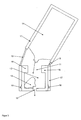
- FIG. 1 shows a schematically illustrated cross-sectional view of a device according to the invention with a compound (1) in which an ampoule head (2) is arranged, wherein the compound (1) connects a cavity (3) with a region in which an ampoule (4) is arranged ,
- the ampoule (4) may for example consist of glass, ceramic or another material.
- On the opposite side of the connection (1) of the cavity (3) has an opening (5) is provided.
- the connection (1) is for example a cylindrical bore in an ampoule pad (6).
- the ampoule pad (6) is part of a cylindrical hollow body, in the bottom surface of which the opening (5) is located.
- Around the ampoule (4) and the cylindrical hollow body around an outer container (7) is arranged.
- the outer container (7) is connected via a thread (8) with the cylindrical hollow body, or with the ampoule pad (6).
- an external thread (8) is provided on the cylindrical hollow body and an internal thread is provided on the outer container (7).
- the outer container (7) is designed as a closed cylindrical hollow body on one side, which consists of a flexible material, such as rubber.
- the cylindrical hollow body with the ampoule pad (6) consists of a stiff, solid material, such as plastic.
- the ampoule (4) is placed upside down in the device, so that a liquid content of the ampoule (4) runs out of this when the ampoule head (2) is broken off.
- the user of such a device can open the ampoule (4) by tilting or bending the upper portion of the outer container (7) against the ampoule support (6). Since the ampoule head (2) can not be tilted out of the connection (1), it remains in the connection (1) stuck and eventually breaks off or breaks completely.
- a predetermined breaking point can be provided at the connection from the ampoule head (2) to the ampoule body, in which, for example, the material from which the ampoule (4) is made is particularly thin or scratched.
- the broken ampoule head (2) falls into the cavity (3).
- the vial head (2) is shaped and weighted to rotate as it descends so that the contents of the vial head (2) can run out of it.
- the contents of the ampoule (4) pours into the cavity (3), since the cavity (3) is arranged below the ampoule (4). Subsequently, the liquid from the cavity (3) passes through the opening (5) and is available to the user.
- the device serves for the liquid contained in the ampoule (4) to be subsequently miscible with a cement in a cement cartridge (not shown).
- the device can be firmly connected to a cartridge system (not shown).
- FIG. 2 shows an alternative embodiment of a device according to the invention in a schematic representation.
- a portion (19) of an outer container (17) is flexible, while the rest of the outer container (17) is inflexible.
- An ampoule (14) is in the upper part of the outer container (17).
- the device shown has already been deformed by a force acting in the figure from the left at the upper end of the outer container (17).
- an ampoule head (12) of the ampoule (14) is broken off.
- the ampoule head (12) could not follow the movement of the ampoule (14) because it is in a compound (11) from a cavity (13) to the upper part of the outer container (17) inserted.
- connection (11) is a recess in an ampoule pad (16), which in turn is part of a hollow body, which is arranged below the ampoule (40).
- the hollow body has a further opening (15).
- the outer container (17) is connected to the hollow body via a snap (18).
- a rigid sleeve (not shown) may be provided, which is arranged around the outer container (17). This sleeve must then be removed before opening the ampoule (14).
- the flexible region (19) may be made of a different material than the rest of the outer container (17).
- both the flexible region (19) and the outer container (17) consist of the same material, wherein the thickness of the material in the flexible region (19) is less than in the walls of the outer container (17) and thereby better deformability in the flexible region (19) is given.
- FIG. 3 shows a schematic representation of the device according to FIG. 2 after the ampoule head (12) has fallen down into the cavity (13).
- the ampoule head (12) When falling, the ampoule head (12) has rotated due to its shape and nature, so that the contents of the ampoule head (12) run out of this into the cavity (13) and finally through the opening (15) expires from the device.
- the contents of the ampoule (14) runs from this into the cavity (13), as indicated by the upper arrow.
- the liquid from the opened ampoule (14) also passes out of the cavity (13) through the opening (15), as indicated by the lower arrow.
- the upper part of the device (outer container (17) with ampoule body) is still in an inclined position.
- the flexible region (19) has thus plastically deformed.
- the upper part but also back to its original position (as in the embodiment according to FIG. 1 and the contents of the ampule (14) would still leak out. So that the ampoule head (12) does not get stuck in the connection (11) in the ampoule support (16), the inner diameter of the connection can be somewhat larger than the outer diameter of the ampoule head (12).
- a suitable form of connection may assist in turning the broken ampule head (12) in the cavity (13) so that the contents of the ampule head (12) will drain.
- the void (13) must be sufficiently large relative to the vial head (12) to allow the vial head (12) to rotate in the void (13).
- the ampoule head (12) may be pointed and elongated, unlike the vial heads shown in the figures. Likewise it can be provided that the ampoule head (12) breaks not only at one, but at several points, so that the contents of the shards of the ampoule head (12) pours into the cavity (13).
- a sieve or a filter (not shown) can be arranged above the opening (15) in the cavity (13).
- FIG. 4 shows a schematic representation of a device according to the invention with an unopened ampoule (24), which is arranged in a cartridge system according to the invention.
- the closed ampoule (24) is mounted in the upper part of an outer container (27), which is connected via a thread (28) with a hollow body which is fixedly arranged on a foot part (50) of the cartridge system.
- the foot part (50) and the hollow body of the device can also be constructed as a common molding, for example made of plastic.
- a cavity (23) is arranged in the hollow body.
- the connection (21) extends through an ampoule support (26) which limits the cavity (23) up to the ampoule (24).
- a filter (60) is placed over an opening (25) intended to separate solid parts, such as shards, from the liquid contents of the ampoule (24).
- the outer container (27) has a circumferentially comprehensive flexible area (29) on which the outer container (27) is deformable. This makes it possible to cancel the ampoule head (22) by the upper portion of the outer container (27) with the body of the ampoule (24) tilted, or is rotated perpendicular to the axis of symmetry of the ampoule (24).
- the opening (25) is connected to a conduit (53) in the foot part (50), which connects the device according to the invention with a cement cartridge (51).
- the liquid from the ampoule (24) can be conveyed by means of a negative pressure through the conduit (53) in the cement cartridge (51). There, the liquid mixes with the cement powder and the mixture can be expelled with the aid of a delivery piston (52) from the cement cartridge (51) and the cement can be applied.
- the movement of the delivery piston can also be forced by applying compressed air.
- the flexible area (29) can also be realized by a bellows.
- the outer container (7, 17, 27) is elastically deformable in the longitudinal direction by mechanical force. This means that the ampoule pad (6, 16, 26) facing away from the closed end of the outer container (7, 17, 27) by a simple movement perpendicular to its axis by a few degrees is movable.
- the in the outer container (7, 17, 27) located ampoule (4, 14, 24) is thus forcibly moved with.
- the ampoule head (2, 12, 22) is located in the hollow cylindrical connection (1, 11, 21) of the ampoule pad (6, 16, 26).
- the ampoule pad (6, 16, 26) is not rubbery. This means that the ampoule body is sheared by movement of the outer container (7, 17, 27) against the non-moving ampoule head (2, 12, 22).
- the inner diameter of the hollow-cylindrical ampoule pad (6, 16, 26) is larger than the ampoule head (2, 12, 22).
- the sheared-off vial head (2, 12, 22) falls through the vial support (6, 16, 26) into the cavity (3, 13, 23) and gives the connection (1, 11, 21) to the vial support (6, 16, 26 ) free for the inflowing monomer liquid.
- This cavity (3, 13, 23) has a height greater than the entire length of the separated ampoule head (2, 12, 22).
- the cross section of the cavity (3, 13, 23) is so large that the sheared ampoule head (2, 12, 22) can lie horizontally at the bottom of the cavity (3, 13, 23).
- the height of the cavity (3, 13, 23) is important so that the separated ampoule head (2, 12, 22) in its fall through the connection (1, 11, 21) in the ampoule pad (6, 16, 26) so can rotate so that it can lie horizontally on the bottom of the cavity (3, 13, 23).
- the volume of monomer liquid present in the ampoule head (2, 12, 22) can run out.
- the cross-section of the break point between the ampoule head (2, 12, 22) and the ampoule body is dimensioned so that a trouble leakage of the ampoule (4, 14, 24) at Gravity is ensured on the monomer liquid.
- the geometry of the ampoule (4, 14, 24) must be adapted to the surface tension of the monomer liquid.
- the outflow of the monomer is made possible by the opening (5, 15, 25) arranged in the bottom of the cavity (3, 13, 23).
- the breaking of the ampoule (4, 14, 24) can be easily followed by the bursting sound, but is also noticeable by the sudden overcoming of the resistance. It is not essential in which direction the outer container (7, 17, 27) is moved perpendicular to the cylinder axis. It is only essential that a relative movement of the upper end of the outer container (7, 17, 27) takes place perpendicular to the ampoule axis.
- the outer container (7, 17, 27) may have a ribbing on the inside parallel to the cylinder axis. As a result, an additional shock absorption of the ampoule (4, 14, 24) during transport is possible.
- the ampoule pad (6, 16, 26) is not elastically deformable.
- the outer container (7, 17, 27) is non-positively and / or positively connected to the ampoule pad (6, 16, 26).
- the outer container (7, 17, 27) can be connected by a simple thread (8, 28) with the ampoule pad (6, 16, 26). It is also possible to form a snapping (18) on the outer container (7, 17, 27), which can be snapped with a circumferential ridge on the vial support (6, 16, 26). It is also possible to put the outer container (7, 17, 27) on the ampoule support (6, 16, 26), so that a fixation by the restoring force of the rubber-elastic outer container (7, 17, 27) is effected.
- the outer container (7, 17, 27) is preferably formed of rubber-elastic plastic.
- the outer container (7, 17, 27) may optionally be formed bellows.
- the outer container (7, 17, 27) may be formed of rubber-elastic material so that only in the height of the break point of the ampoule (4, 14, 24) such a thin wall (19, 29) is present that this is elastomeric and that the rest of the outer container (7, 17, 27) has a thicker wall, which is no longer elastically deformable.
- the deformable regions (19, 29) are then thinner than the walls of the outer container (7, 17, 27).
- the invention also provides a method for opening ampoules, which is characterized in that the outer container (7, 17, 27) with the closed ampoule (4, 14, 24) from its cylinder axis by movement of the ampoule pad (6, 16, 26 ) is moved opposite the end of the outer container (7, 17, 27) so that the ampoule body is moved against the inside of the ampoule support (6, 16, 26) fixed ampoule head (2, 12, 22), whereby the ampoule head (2 , 12, 22) is broken by the ampoule body.
Abstract
Description
Die Erfindung betrifft eine Vorrichtung zum Öffnen von Ampullen umfassend einen Außenbehälter, in dem eine geschlossene Ampulle mit einem Ampullenkörper und einem Ampullenkopf angeordnet ist, und umfassend einen Hohlraum im Bereich des Ampullenkopfs, wobei der Hohlraum zumindest eine Öffnung und eine Verbindung zur Ampulle umfasst.The invention relates to a device for opening ampoules comprising an outer container, in which a closed ampoule is arranged with an ampoule body and an ampoule head, and comprising a cavity in the region of the ampoule head, wherein the cavity comprises at least one opening and a connection to the ampoule.
Damit stellt die Erfindung eine robuste Vorrichtung zur Lagerung und zum Öffnen von Monomerampullen von Vakuumzementiersystemen für Polymethylmethacrylat-Knochenzemente bereit, die mit Zementpulver und Monomerflüssigkeit vorgefüllt sind und als Full-Prepack-Vakuumzementiersysteme dem medizinischen Anwender zur Verfügung gestellt werden.Thus, the invention provides a robust apparatus for storing and opening monomer vials of vacuum cementing systems for polymethyl methacrylate bone cements pre-filled with cement powder and monomer liquid and provided to the medical user as full-pre-pack vacuum cementing systems.
PMMA-Knochenzemente sind seit Jahrzehnten bekannt und gehen auf die grundlegenden Arbeiten von Sir Charnley zurück (
Polymethylmethacrylat-Knochenzemente können in geeigneten Mischbechern mit Hilfe von Spateln durch Vermischen des Zementpulvers mit der Monomerflüssigkeit vermischt werden. Nachteilig ist an dieser Vorgehensweise, dass Lufteinschlüsse im gebildeten Zementteig vorhanden sein können, die später eine Destabilisierung des Knochenzementes verursachen können. Aus diesem Grund wird das Vermischen von Knochenzementpulver mit der Monomerflüssigkeit in Vakuummischsystemen bevorzugt, weil durch Mischen im Vakuum Lufteinschlüsse aus dem Zementteig weitgehend entfernt werden und damit eine optimale Zementqualität erreicht wird (
Eine Weiterentwicklung stellen Zementiersysteme dar, in denen sowohl das Zementpulver als auch die Monomerflüssigkeit bereits in separaten Kompartimenten der Mischsysteme verpackt sind und erst unmittelbar vor der Zementapplikation im Zementiersystem miteinander vermischt werden (
Aluminiumverbundbeutel sind für die Verpackung und Lagerung von Monomerflüssigkeit erst seit wenigen Jahren bekannt. Sehr gute Erfahrungen hinsichtlich der Lagerfähigkeit von Monomerflüssigkeit liegen mit Glasampullen vor. Glasampullen werden seit Jahrzehnten für konventionelle Polymethylmethacrylat-Knochenzemente mit gutem Erfolg eingesetzt. Glasampullen haben neben der perfekten Dichtigkeit auch den Vorteil, dass sie in großen Stückzahlen zu niedrigen Preisen gefertigt werden können. Daher ist es sinnvoll, Glasampullen zur Verpackung und Lagerung von Monomerflüssigkeit in Prepack-Vakuumzementiersystemen einzusetzen.Aluminum composite bags have only been known for the packaging and storage of monomer liquid for a few years. Very good experiences with respect to the storability of monomer liquid are available with glass ampoules. Glass ampoules have been used successfully for decades for conventional polymethyl methacrylate bone cements. Glass ampoules have in addition to the perfect tightness also the advantage that they in large numbers too low prices can be made. Therefore, it makes sense to use glass ampoules for packaging and storage of monomer liquid in pre-pack vacuum cementing systems.
In der
In der
Ein System zum Öffnen von Ampullen bei Zementiersystemen wird in der
In der
Der wesentliche Nachteil der in den zitierten Offenlegungsschriften dargestellten Öffnungsvorrichtungen besteht darin, dass bewegte mechanische Teile notwendig sind, die verklemmen können und deren Fertigung hinsichtlich der Fertigungstoleranzen relativ hohen Ansprüchen genügen müssen, um eine Funktionsfähigkeit zu gewährleisten.The main disadvantage of the opening devices shown in the cited published documents is that moving mechanical parts are necessary, which can jam and whose production must meet relatively high standards in terms of manufacturing tolerances to ensure proper functioning.
Aus der
Obwohl das Öffnen der Ampulle durch diesen Aufbau sehr einfach ist, ist der komplexe Aufbau des Sicherheitsventils mit der Vielzahl an Einzelkomponenten nachteilig. Zum einen führt dies zu erhöhten Kosten bei der Fertigung einer solchen Öffnungsvorrichtung, zum anderen kann bei der Fertigung der Öffnungsvorrichtung die Ampulle versehentlich geöffnet werden.Although the opening of the ampoule is very simple by this structure, the complex structure of the safety valve with the large number of individual components is disadvantageous. On the one hand, this leads to increased costs in the production of such an opening device, on the other hand, the ampoule can be opened accidentally in the manufacture of the opening device.
Die Aufgabe der Erfindung ist die Entwicklung einer robusten, möglichst einfachen Vorrichtung zur Lagerung und zum Öffnen von Monomerampullen von Vakuumzementiersystemen für Polymethylmethacrylat-Knochenzemente, die bereits mit Zementpulver und Monomerflüssigkeit vorgefüllt sind und als Prepac-Vakuumzementiersysteme dem medizinischen Anwender zur Verfügung gestellt werden können. Die Vorrichtung soll aus einer minimalen Anzahl von Teilen bestehen und kostengünstig zu fertigen sein. Die Fertigung soll zudem zuverlässig ohne die Gefahr der Zerstörung der Ampullen möglich sein. Vom Anwender ohne spezielle Vorkenntnisse muss die Vorrichtung schnell und sicher zur Öffnung von Monomerampullen eingesetzt den können. Es darf bei der Vorrichtung keine Verklemmung während des Öffnens der Ampulle möglich sein.The object of the invention is the development of a robust, as simple as possible device for storage and opening of monomer vials of Vakuumztementiersystemen for polymethylmethacrylate bone cements, which are already prefilled with cement powder and monomer liquid and can be made available to the medical user as Prepac Vakuumzementiersysteme. The device should consist of a minimum number of parts and be inexpensive to manufacture. The production should also be possible reliably without the risk of destroying the ampoules. From the user without special knowledge, the device must be used quickly and safely for the opening of monomer vials. It must be possible in the device no jamming during the opening of the ampoule.
Diese Aufgabe wird dadurch gelöst, dass der Ampullenkopf zumindest bereichsweise in der Verbindung des Hohlraums zur Ampulle angeordnet ist und die Wände des Außenbehälters wenigstens einen verformbaren Bereich umfassen oder komplett aus einem verformbaren Material bestehen, wodurch ein Verkippen der Ampulle gegen die Verbindung ermöglicht ist, und der Durchmesser der Verbindung derart an die Abmessungen des Ampullenkopfs angepasst ist, dass der Ampullenkopf bei einem Verkippen der Ampulle gegen die Verbindung zerbrechbar oder vom Ampullenkörper abbrechbar ist.This object is achieved in that the ampoule head is at least partially disposed in the connection of the cavity to the ampoule and the walls of the outer container comprise at least one deformable region or consist entirely of a deformable material, whereby a tilting of the ampoule against the compound is enabled, and the diameter of the connection is adapted to the dimensions of the ampoule head such that the ampoule head is breakable when the ampoule is tilted against the connection or can be broken off from the ampoule body.
Dabei kann vorgesehen sein, dass der verformbare Bereich den gesamten Umfang des Außenbehälters umschließt.It can be provided that the deformable region encloses the entire circumference of the outer container.
Auch kann vorgesehen sein, dass der Innendurchmesser der Verbindung gleich groß oder größer, vorzugsweise 0,5 - 1,5 mm größer und insbesondere 1 mm größer, als der Außendurchmesser des Ampullenkopfs ist.It can also be provided that the inner diameter of the connection is the same size or larger, preferably 0.5-1.5 mm larger and in particular 1 mm larger than the outer diameter of the ampoule head.
Eine weitere vorteilhafte Ausgestaltung der Erfindung ergibt sich, wenn die Höhe'und der Querschnitt des Hohlraums mindestens so groß wie die Höhe des Ampullenkopfs bis zur Bruchkante der Ampulle sind.A further advantageous embodiment of the invention results when the height 'and the cross section of the cavity are at least as large as the height of the ampoule head to the breaking edge of the ampoule.
Es ist auch vorteilhaft, wenn am Boden des Hohlraums über der Öffnung ein Filter und/oder ein Sieb angeordnet ist.It is also advantageous if at the bottom of the cavity above the opening a filter and / or a sieve is arranged.
Ferner kann vorgesehen sein, dass die Vorrichtung durch Anlegen von Vakuum bis 90 mbar Unterdruck nicht visuell erkennbar deformierbar ist.Furthermore, it can be provided that the device is not visually recognizable deformable by applying vacuum to 90 mbar vacuum.
Eine besonders vorteilhafte Ausgestaltung der Erfindung sieht vor, dass der Außenbehälter an einem Hohlkörper befestigt ist, in dem der Hohlraum ausgebildet ist, wobei der Hohlkörper die Öffnung umfasst und aus einem festen nicht mit Hand verformbaren Material besteht.A particularly advantageous embodiment of the invention provides that the outer container is attached to a hollow body in which the cavity is formed, wherein the hollow body comprises the opening and consists of a solid non-hand deformable material.
Dabei kann vorgesehen sein, dass der insbesondere zylindrische Hohlkörper auf der Oberseite durch eine Ampullenauflage begrenzt ist, in der die Verbindung angeordnet ist.It can be provided that the particular cylindrical hollow body is limited on the upper side by an ampoule pad in which the compound is arranged.
Ferner kann vorgesehen sein, dass der Außenbehälter kraftschlüssig und/oder formschlüssig, insbesondere mit einem Gewinde und/oder einer Schnappung, am Hohlkörper befestigt ist.Furthermore, it can be provided that the outer container is positively and / or positively, in particular with a thread and / or a snap, attached to the hollow body.
Für erfindungsgemäße Vorrichtungen wird auch vorgeschlagen, dass die Ampulle an der Verbindung des Ampullenkörpers zum Ampullenkopf eine Sollbruchstelle aufweist.For devices according to the invention it is also proposed that the ampoule has a predetermined breaking point at the connection of the ampoule body to the ampoule head.
Bevorzugt ist auch, dass der Außenbehälter aus gummielastischem Kunststoff ausgebildet ist und/oder dass der Außenbehälter zumindest in einem Bereich balgartig ausgeformt ist.It is also preferred that the outer container is formed of rubber-elastic plastic and / or that the outer container is formed bellows-like at least in one area.
Um die Fertigung weiter zu vereinfachen kann ferner vorgesehen sein, dass der Außenbehälter, die Ampulle und/oder die Verbindung rotationssymmetrisch, insbesondere zylindrisch sind. Eine weitere, besonders einfache Ausgestaltung der Erfindung sieht vor, dass der Außenbehälter ein beidseitig offener Zylindermantel, insbesondere ein Schrumpfschlauch, ist, der die Ampulle und den Hohlkörper gasdicht miteinander verbindet.In order to further simplify the production, it may further be provided that the outer container, the ampoule and / or the connection are rotationally symmetrical, in particular cylindrical. A further, particularly simple embodiment of the invention provides that the outer container is a cylinder jacket open on both sides, in particular a heat-shrinkable tube, which connects the ampoule and the hollow body to one another in a gastight manner.
Mit der Erfindung wird zudem ein Kartuschensystem umfassend eine Vorrichtung nach einem der vorangehenden Ansprüche und eine Zementkartusche, die mit der Öffnung über eine Leitung verbunden ist, vorgeschlagen.The invention also proposes a cartridge system comprising a device according to one of the preceding claims and a cement cartridge which is connected to the opening via a conduit.
Dabei kann vorgesehen sein, dass die Vorrichtung und die Zementkartusche an einem Fußteil angeordnet sind und die Vorrichtung derart auf dem Fußteil befestigt ist, dass Flüssigkeit aufgrund der Schwerkraft und/oder aufgrund eines Differenzdrucks aus der geöffneten Ampulle durch den Hohlraum und die Öffnung in die Leitung im Fußteil fließt.It can be provided that the device and the cement cartridge are arranged on a foot part and the device is mounted on the foot part such that liquid due to gravity and / or due to a differential pressure from the open ampoule through the cavity and the opening in the line flowing in the foot part.
Der Erfindung liegt also die überraschende Erkenntnis zugrunde, dass ein beweglicher Außenbehälter dazu genutzt werden kann, um eine darin gelagerte Ampulle zu öffnen, wenn der Ampullenkopf gegen die Bewegung des Außenbehälters fixiert ist. Dadurch wird auf einfachste Weise erreicht, dass der der Ampullenkörper gegen den Ampullenkopf bewegt werden kann, wodurch der Ampullenkopf zerbricht oder vom Ampullenkörper abbricht.The invention is therefore based on the surprising finding that a movable outer container can be used to open an ampoule stored therein when the ampoule head is fixed against the movement of the outer container. This achieves in the simplest way that the ampoule body can be moved against the ampoule head, whereby the ampoule head breaks or breaks off from the ampoule body.
In ihrer einfachsten Ausgestaltung steckt eine Ampulle mit dem Ampullenkopf lose in einer Halterung mit einer zylindrischen Bohrung unter der sich ein größerer Hohlraum mit einem Loch befindet. Ein flexibler Außenbehälter wird über die Ampulle und die Halterung gestülpt und zumindest an der Halterung gasdicht fixiert. Die dichte Fixierung an der Halterung reicht aus, wenn der flexible Außenbehälter ein einseitig geschlossener Hohlzylinder ist. Ist der Außenbehälter ein beidseitig offener Zylinder, wie beispielsweise ein Schrumpfschlauch, muss auch eine dichte Fixierung des Außenbehälters an der Ampulle vorgesehen sein.In its simplest embodiment, an ampoule with the ampoule head is loosely placed in a holder with a cylindrical bore below which there is a larger cavity with a hole. A flexible outer container is placed over the ampoule and the holder and fixed gas-tight at least on the holder. The tight fixation on the bracket is sufficient if the flexible outer container is a hollow cylinder closed on one side. If the outer container is a cylinder open on both sides, such as a heat-shrinkable tube, a tight fixing of the outer container to the ampoule must also be provided.
Der Aufbau ist dadurch besonders einfach und kostengünstig zu realisieren. Gleichzeitig ist die Bedienung aber einfach und sicher. Auch in schwierigen Umständen, wie bei chirurgischen Operationen, ist die Anwendung einfach und auch von ungelerntem Hilfspersonal ohne weiteres möglich.The structure is thereby particularly simple and inexpensive to implement. At the same time, the operation is simple and safe. Even in difficult circumstances, such as surgical operations, the application is easy and even by unskilled assistants readily possible.
Um ein ungewolltes umknicken und damit eine unerwünschte Öffnung der Ampulle zu verhindern, kann vorgesehen sein, dass eine steife Hülse über den flexiblen Bereich der Außenhülle angeordnet ist.In order to prevent unwanted bending and thus prevent unwanted opening of the ampoule, it can be provided that a rigid sleeve is arranged over the flexible region of the outer shell.
Diese Hülse verhindert ein Verkippen der Ampulle und muss vor der Benutzung abgezogen werden.This sleeve prevents tilting of the ampoule and must be withdrawn before use.
Die Fixierung des Ampullenkopfs kann fest mit einem Kartuschensystem verbunden sein, so dass ein Anwender des Kartuschensystems, der dieses in einer Hand hält, die Ampulle leicht mit der anderen Hand durch Verkippen des Außenbehälters, beziehungsweise der Ampulle öffnen kann. Dadurch wird das gesamte Kartuschensystem einsatzbereit.The fixation of the ampoule head can be firmly connected to a cartridge system, so that a user of the cartridge system, which holds this in one hand, the ampoule easily with the other hand by tilting the outer container, or the ampoule can open. This will make the entire cartridge system ready for use.
Als Hohlraum im Sinne der vorliegenden Erfindung ist auch eine einfache Leitung zu verstehen, die nicht notwendig groß genug sein muss, um den abgebrochenen Ampullenkopf aufzunehmen. Der Übergang vom Hohlraum zur Öffnung kann dann nicht mehr unterschieden werden. Auch der Übergang von der Verbindung zum Hohlraum kann stufenlos sein. Es muss lediglich darauf geachtet werden, dass der abgebrochene Ampullenkopf das Auslaufen des Inhalts der Ampulle nicht vollständig verhindert. Ein Hohlraum, der ausreichend dimensioniert ist, um den Ampullenkopf aufzunehmen, oder der sogar dazu geeignet ist, eine Drehung des abgebrochenen Ampullenkopfs im Hohlraum zu ermöglichen, ist jedoch besonders vorteilhaft, da dann auch der flüssige Inhalt des abgebrochenen Ampullenkopfs ausströmen kann und so zur weiteren Verwendung nutzbar ist.As a cavity in the context of the present invention, a simple line is to be understood, which need not necessarily be large enough to accommodate the broken ampoule head. The transition from the cavity to the opening can then no longer be distinguished. The transition from the connection to the cavity can also be stepless. It only needs to be taken to ensure that the broken ampoule head does not completely prevent the leakage of the contents of the ampoule. However, a cavity sufficiently sized to receive the ampoule head, or even capable of allowing rotation of the broken ampoule head in the cavity, is particularly advantageous because then the liquid contents of the broken ampoule head can flow out and so forth Use is usable.
Die Verbindung dient hauptsächlich der Fixierung des Ampullenkopfs gegen eine Kippbewegung der Ampulle. Zudem soll eine Fluidverbindung zum Hohlraum, beziehungsweise zu der Öffnung und der gegebenenfalls angeschlossenen Leitung hergestellt werden.The compound is mainly used to fix the ampoule head against a tilting movement of the ampoule. In addition, a fluid connection to the cavity, or to the opening and the optionally connected line to be made.
Über die Öffnung kann auch ein Unterdruck im Hohlraum und im Inneren des Außenbehälters erzeugt werden. Dadurch kann der Inhalt der Ampulle auch durch die Öffnung gesaugt, beziehungsweise genauer durch den höheren Druck in der Ampulle oder von außen gedrückt werden. Zudem kann bei geeigneter Stellung der Vorrichtung auch die Schwerkraft genutzt werden, um den Inhalt der Ampulle durch die Verbindung, den Hohlraum und die Öffnung fließen zu lassen.A negative pressure in the cavity and in the interior of the outer container can also be generated via the opening. As a result, the contents of the ampoule can also be sucked through the opening, or more precisely pressed through the higher pressure in the ampoule or from the outside. In addition, when the device is in a suitable position, gravity can also be used to allow the contents of the ampoule to flow through the connection, the cavity and the opening.
Im Folgenden werden Ausführungsbeispiele der Erfindung anhand von vier schematisch dargestellten Zeichnungen erläutert. Dabei zeigt:
- Figur 1:
- eine schematische Querschnittansicht in Längsrichtung einer erfindungsgemäßen Vor- richtung mit verschlossener Ampulle;
- Figur 2:
- eine schematische Querschnittansicht in Längsrichtung einer alternativen erfindungs- gemäßen Vorrichtung mit geöffneter Ampulle;
- Figur 3:
- eine schematische Querschnittansicht der erfindungsgemäßen Vorrichtung nach
Figur 2 mit herabgefallenem Ampullenkopf; und - Figur 4:
- eine schematische Querschnittansicht einer erfindungsgemäßen Vorrichtung, in einem erfindungsgemäßen Kartuschensystem.
- FIG. 1:
- a schematic cross-sectional view in the longitudinal direction of a device according to the invention with closed ampoule;
- FIG. 2:
- a schematic cross-sectional view in the longitudinal direction of an alternative device according to the invention with open ampoule;
- FIG. 3:
- a schematic cross-sectional view of the device according to the invention
FIG. 2 with dropped ampoule head; and - FIG. 4:
- a schematic cross-sectional view of a device according to the invention, in a cartridge system according to the invention.
Die Außenbehälter (7) ist als einseitig geschlossener zylindrischer Hohlkörper ausgebildet, der aus einem flexiblen Material, wie beispielsweise Gummi, besteht. Der zylindrische Hohlkörper mit der Ampullenauflage (6) besteht dagegen aus einem steifen, festen Material, wie beispielsweise Kunststoff. Die Ampulle (4) ist kopfüber in der Vorrichtung angeordnet, so dass ein flüssiger Inhalt der Ampulle (4) aus dieser heraus läuft, wenn der Ampullenkopf (2) abgebrochen wird.The outer container (7) is designed as a closed cylindrical hollow body on one side, which consists of a flexible material, such as rubber. The cylindrical hollow body with the ampoule pad (6), however, consists of a stiff, solid material, such as plastic. The ampoule (4) is placed upside down in the device, so that a liquid content of the ampoule (4) runs out of this when the ampoule head (2) is broken off.
Der Anwender einer solchen Vorrichtung kann die Ampulle (4) öffnen, indem er den oberen Bereich des Außenbehälters (7) gegen die Ampullenauflage (6) kippt beziehungsweise verbiegt. Da der Ampullenkopf (2) nicht aus der Verbindung (1) heraus gekippt werden kann, bleibt er in der Verbindung (1) stecken und bricht schließlich ab oder zerbricht ganz. Dazu kann an der Verbindung vom Ampullenkopf (2) zum Ampullenkörper eine Sollbruchstelle vorgesehen sein, in der beispielsweise das Material, aus dem die Ampulle (4) gefertigt ist, besonders dünn oder angeritzt ist. Der abgebrochene Ampullenkopf (2) fällt in den Hohlraum (3). Idealerweise ist der Ampullenkopf (2) derart geformt und gewichtet, dass er sich beim abfallen dreht, so dass der Inhalt des Ampullenkopfs (2) aus diesem heraus laufen kann.The user of such a device can open the ampoule (4) by tilting or bending the upper portion of the outer container (7) against the ampoule support (6). Since the ampoule head (2) can not be tilted out of the connection (1), it remains in the connection (1) stuck and eventually breaks off or breaks completely. For this purpose, a predetermined breaking point can be provided at the connection from the ampoule head (2) to the ampoule body, in which, for example, the material from which the ampoule (4) is made is particularly thin or scratched. The broken ampoule head (2) falls into the cavity (3). Ideally, the vial head (2) is shaped and weighted to rotate as it descends so that the contents of the vial head (2) can run out of it.
Gleichzeitig ergießt sich auch der Inhalt der Ampulle (4) in den Hohlraum (3), da der Hohlraum (3) unterhalb der Ampulle (4) angeordnet ist. Anschließend läuft die Flüssigkeit aus dem Hohlraum (3) durch die Öffnung (5) und steht dem Anwender zur Verfügung.At the same time, the contents of the ampoule (4) pours into the cavity (3), since the cavity (3) is arranged below the ampoule (4). Subsequently, the liquid from the cavity (3) passes through the opening (5) and is available to the user.
Im vorliegenden Fall dient die Vorrichtung dazu, dass die in der Ampulle (4) enthaltene Flüssigkeit anschließend mit einem Zement in einer Zementkartusche (nicht gezeigt) mischbar ist. Dazu kann die Vorrichtung fest mit einem Kartuschensystem (nicht gezeigt) verbunden sein.In the present case, the device serves for the liquid contained in the ampoule (4) to be subsequently miscible with a cement in a cement cartridge (not shown). For this purpose, the device can be firmly connected to a cartridge system (not shown).
Die Verbindung (11) ist eine Ausnehmung in einer Ampullenauflage (16), die wiederum Teil eines Hohlkörper ist, der unterhalb der Ampulle (40) angeordnet ist. Der Hohlkörper weist eine weitere Öffnung (15) auf. Der Außenbehälter (17) ist mit dem Hohlkörper über eine Schnappung (18) verbunden.The connection (11) is a recess in an ampoule pad (16), which in turn is part of a hollow body, which is arranged below the ampoule (40). The hollow body has a further opening (15). The outer container (17) is connected to the hollow body via a snap (18).
Damit der Ampullenkopf (12) nicht schon bei der Fertigung oder beim Transport abbricht, kann eine steife Hülse (nicht gezeigt) vorgesehen sein, die um den Außenbehälter (17) herum angeordnet ist. Diese Hülse muss dann vor dem öffnen der Ampulle (14) entfernt werden. Der flexible Bereich (19) kann aus einem anderen Material bestehen als der Rest des Außenbehälters (17). Alternativ kann auch vorgesehen sein, dass sowohl der flexible Bereich (19) als auch der Außenbehälter (17) aus dem gleichen Material bestehen, wobei die Stärke des Materials im flexiblen Bereich (19) geringer ist als in den Wänden des Außenbehälters (17) und dadurch eine bessere Verformbarkeit im flexiblen Bereich (19) gegeben ist.So that the ampoule head (12) does not break off during manufacture or during transport, a rigid sleeve (not shown) may be provided, which is arranged around the outer container (17). This sleeve must then be removed before opening the ampoule (14). The flexible region (19) may be made of a different material than the rest of the outer container (17). Alternatively, it can also be provided that both the flexible region (19) and the outer container (17) consist of the same material, wherein the thickness of the material in the flexible region (19) is less than in the walls of the outer container (17) and thereby better deformability in the flexible region (19) is given.
Der obere Teil der Vorrichtung (Außenbehälter (17) mit Ampullenkörper) befindet sich noch immer in Schräglage. Der flexible Bereich (19) hat sich also plastisch verformt. Ebenso könnte bei elastischer Verformbarkeit des flexiblen Bereichs (19) bei nur kurzzeitiger Krafteinwirkung der obere Teil aber auch wieder in seine Ausgangsposition (wie bei dem Ausführungsbeispiel nach
Eine geeignete Form der Verbindung kann unterstützen, dass sich der abgebrochene Ampullenkopf (12) im Hohlraum (13) so dreht, dass der Inhalt des Ampullenkopfs (12) ausläuft. Der Hohlraum (13) muss in Bezug auf den Ampullenkopf (12) ausreichend groß sein, damit der Ampullenkopf (12) sich im Hohlraum (13) drehen kann. Der Ampullenkopf (12) kann dazu, im Gegensatz zu den in den Figuren gezeigten Ampullenköpfen, spitz und länglich geformt sein. Ebenso kann vorgesehen sein, dass der Ampullenkopf (12) nicht nur an einer, sondern an mehreren Stellen bricht, so dass sich der Inhalt aus den Scherben des Ampullenkopfs (12) in den Hohlraum (13) ergießt.A suitable form of connection may assist in turning the broken ampule head (12) in the cavity (13) so that the contents of the ampule head (12) will drain. The void (13) must be sufficiently large relative to the vial head (12) to allow the vial head (12) to rotate in the void (13). The ampoule head (12) may be pointed and elongated, unlike the vial heads shown in the figures. Likewise it can be provided that the ampoule head (12) breaks not only at one, but at several points, so that the contents of the shards of the ampoule head (12) pours into the cavity (13).
Damit keine Scherben durch die Öffnung (15) austreten, kann oberhalb der Öffnung (15) im Hohlraum (13) ein Sieb oder ein Filter (nicht gezeigt) angeordnet sein.So that no broken pieces emerge through the opening (15), a sieve or a filter (not shown) can be arranged above the opening (15) in the cavity (13).
Die geschlossene Ampulle (24) ist in im oberen Teil eines Außenbehälters (27) gelagert, der über ein Gewinde (28) mit einem Hohlkörper verbunden ist, der fest auf einem Fußteil (50) des Kartuschensystems angeordnet ist. Das Fußteil (50) und der Hohlkörper der Vorrichtung können auch als ein gemeinsames Formteil, beispielsweise aus Kunststoff aufgebaut sein.The closed ampoule (24) is mounted in the upper part of an outer container (27), which is connected via a thread (28) with a hollow body which is fixedly arranged on a foot part (50) of the cartridge system. The foot part (50) and the hollow body of the device can also be constructed as a common molding, for example made of plastic.
In dem Hohlkörper ist ein Hohlraum (23) angeordnet. Ein Ampullenkopf (22) der Ampulle (24), die kopfüber in der Vorrichtung gelagert ist, ist in einer Verbindung (21) vom Hohlraum (23) zur Ampulle (24) angeordnet. Die Verbindung (21) erstreckt sich durch eine Ampullenauflage (26), die den Hohlraum (23) nach oben zur Ampulle (24) hin begrenzt. Am Boden des Hohlraums (23) ist ein Filter (60) über einer Öffnung (25) angeordnet, der feste Teile, wie beispielsweise Scherben, von dem flüssigen Inhalt der Ampulle (24) trennen soll. Der Außenbehälter (27) hat einen, den gesamten Umfang umfassenden flexiblen Bereich (29), an dem der Außenbehälter (27) verformbar ist. Dadurch ist es möglich, den Ampullenkopf (22) abzubrechen, indem der obere Bereich des Außenbehälters (27) mit dem Körper der Ampulle (24) verkippt, beziehungsweise senkrecht zur Symmetrieachse der Ampulle (24) gedreht wird.In the hollow body, a cavity (23) is arranged. An ampoule head (22) of the ampoule (24), which is mounted upside down in the device, is arranged in a connection (21) from the cavity (23) to the ampoule (24). The connection (21) extends through an ampoule support (26) which limits the cavity (23) up to the ampoule (24). At the bottom of the cavity (23) a filter (60) is placed over an opening (25) intended to separate solid parts, such as shards, from the liquid contents of the ampoule (24). The outer container (27) has a circumferentially comprehensive flexible area (29) on which the outer container (27) is deformable. This makes it possible to cancel the ampoule head (22) by the upper portion of the outer container (27) with the body of the ampoule (24) tilted, or is rotated perpendicular to the axis of symmetry of the ampoule (24).
Die Öffnung (25) ist mit einer Leitung (53) im Fußteil (50) verbunden, die die erfindungsgemäße Vorrichtung mit einer Zementkartusche (51) verbindet. Die Flüssigkeit aus der Ampulle (24) kann mit Hilfe eines Unterdrucks durch die Leitung (53) in die Zementkartusche (51) gefördert werden. Dort mischt sich die Flüssigkeit mit dem Zementpulver und die Mischung kann mit Hilfe eines Förderkolbens (52) aus der Zementkartusche (51) ausgetrieben und der Zement so appliziert werden. Die Bewegung des Förderkolbens kann auch durch Beaufschlagung mit Druckluft erzwungen werden.The opening (25) is connected to a conduit (53) in the foot part (50), which connects the device according to the invention with a cement cartridge (51). The liquid from the ampoule (24) can be conveyed by means of a negative pressure through the conduit (53) in the cement cartridge (51). There, the liquid mixes with the cement powder and the mixture can be expelled with the aid of a delivery piston (52) from the cement cartridge (51) and the cement can be applied. The movement of the delivery piston can also be forced by applying compressed air.
Der flexible Bereich (29) kann auch durch einen Faltenbalg realisiert werden.The flexible area (29) can also be realized by a bellows.
Eine erfindungsgemäße Vorrichtung zur Lagerung und zum Öffnen von Monomerampullen von Vakuumzementiersystemen kann also dadurch gekennzeichnet sein, dass eine hohlzylinderförmige Ampullenauflage (6, 16, 26) eine Verbindung (1, 11, 21) bildet, deren Innendurchmesser gleich oder größer dem Ampullenkopf (2, 12, 22) ist, dass unterhalb der Ampullenauflage (6, 16, 26) bzw. der Verbindung (1, 11, 21) ein Hohlraum (3, 13, 23) vorhanden ist, dessen Höhe mindestens gleich der Länge des Ampullenkopfs (2, 12, 22) bis zur Bruchkante der Ampulle (4, 14, 24) ist und dessen Querschnitt so groß ist, dass der von der Ampulle (4, 14, 24) am abgebrochene Ampullenkopf (2, 12, 22) horizontal auf der Unterseite des Hohlraums (3, 13, 23) liegen kann, dass an der Unterseite des Hohlraums (3, 13, 23) eine Öffnung (5, 15, 25) angeordnet ist, die den Hohlraum (3, 13, 23) mit der Zementkartusche (51) verbindet, und dass ein in Längsrichtung elastisch verformbarer als einseitig geschlossener Hohlzylinder ausgebildeter Außenbehälter (7, 17, 27) mit der Ampullenauflage (6, 16, 26) so verbunden ist, dass sich der Ampullenkopf (2, 12, 22) in der Verbindung (1, 11, 21) über dem Hohlraum (3, 13, 23) in der Ampullenauflage (6, 16, 26) befindet. Dabei kann vorgesehen sein, dass die Vorrichtung durch Anlegen von Vakuum bis 90 mbar Unterdruck nicht visuell erkennbar deformiert wird.A device according to the invention for storing and opening monomer ampoules of vacuum cementing systems can thus be characterized in that a hollow-cylindrical ampoule support (6, 16, 26) forms a connection (1, 11, 21) whose inner diameter is equal to or greater than the ampoule head (2, 12, 22) is that below the ampoule pad (6, 16, 26) or the connection (1, 11, 21), a cavity (3, 13, 23) is present whose height is at least equal to the length of the ampoule head (2 , 12, 22) to the breaking edge of the ampoule (4, 14, 24) and whose cross section is so large that the from the ampoule (4, 14, 24) at the broken ampoule head (2, 12, 22) horizontally on the Bottom of the cavity (3, 13, 23) may be that on the underside of the cavity (3, 13, 23) an opening (5, 15, 25) is arranged is that connects the cavity (3, 13, 23) with the cement cartridge (51), and that an outer container (7, 17, 27) formed in the longitudinal direction elastically deformable as a hollow cylinder closed on one side with the ampoule support (6, 16, 26) is connected so that the ampoule head (2, 12, 22) in the connection (1, 11, 21) over the cavity (3, 13, 23) in the ampoule pad (6, 16, 26) is located. It can be provided that the device is not deformed visually recognizable by applying vacuum to 90 mbar vacuum.
Der Außenbehälter (7, 17, 27) ist in Längsrichtung elastisch durch mechanische Krafteinwirkung verformbar. Das bedeutet, dass das der Ampullenauflage (6, 16, 26) abgewandte verschlossene Ende des Außenbehälters (7, 17, 27) durch einfache Bewegung senkrecht zu seiner Achse um einige wenige Grad bewegbar ist. Die im Außenbehälter (7, 17, 27) befindliche Ampulle (4, 14, 24) wird damit zwangsweise mit bewegt. Der Ampullenkopf (2, 12, 22) befindet sich in der hohlzylinderförmigen Verbindung (1, 11, 21) der Ampullenauflage (6, 16, 26). Die Ampullenauflage (6, 16, 26) ist nicht gummielastisch. Das bedeutet, der Ampullenkörper wird durch Bewegung des Außenbehälters (7, 17, 27) gegen den sich nicht mitbewegenden Ampullenkopf (2, 12, 22) geschert. Der Innendurchmesser der hohlzylinderfömigen Ampullenauflage (6, 16, 26) ist größer als der Ampullenkopf (2, 12, 22). Der abgescherte Ampullenkopf (2, 12, 22) fällt durch die Ampullenauflage (6, 16, 26) in den Hohlraum (3, 13, 23) und gibt die Verbindung (1, 11, 21) der Ampullenauflage (6, 16, 26) für die nachströmende Monomerflüssigkeit frei. Dieser Hohlraum (3, 13, 23) hat eine Höhe größer als die gesamte Länge des abgetrennten Ampullenkopfs (2, 12, 22). Der Querschnitt des Hohlraums (3, 13, 23) ist so groß, dass der abgescherte Ampullenkopf (2, 12, 22) horizontal am Boden des Hohlraums (3, 13, 23) liegen kann. Die Höhe des Hohlraums (3, 13, 23) ist wichtig, damit der abgetrennte Ampullenkopf (2, 12, 22) bei seinem Fall durch die Verbindung (1, 11, 21) in der Ampullenauflage (6, 16, 26) sich so drehen kann, dass er horizontal auf dem Boden des Hohlraums (3, 13, 23) liegen kann. Dadurch kann das in dem Ampullenkopf (2, 12, 22) befindliche Volumen an Monomerflüssigkeit auslaufen. Es muss jedoch beachtet werden, dass in Abhängigkeit von der Oberflächenspannung der jeweiligen Monomerflüssigkeit der Querschnitt der Bruchstelle zwischen dem Ampullenkopf (2, 12, 22) und dem Ampullenkörper so dimensioniert wird, dass ein problemloses Auslaufen der Ampulle (4, 14, 24) bei Einwirkung von Schwerkraft auf die Monomerflüssigkeit gewährleistet wird. Die Geometrie der Ampulle (4, 14, 24) muss der Oberflächenspannung der Monomerflüssigkeit angepasst sein. Der Abfluss des Monomers wird durch die im Boden des Hohlraums (3, 13, 23) angeordnete Öffnung (5, 15, 25) ermöglicht.The outer container (7, 17, 27) is elastically deformable in the longitudinal direction by mechanical force. This means that the ampoule pad (6, 16, 26) facing away from the closed end of the outer container (7, 17, 27) by a simple movement perpendicular to its axis by a few degrees is movable. The in the outer container (7, 17, 27) located ampoule (4, 14, 24) is thus forcibly moved with. The ampoule head (2, 12, 22) is located in the hollow cylindrical connection (1, 11, 21) of the ampoule pad (6, 16, 26). The ampoule pad (6, 16, 26) is not rubbery. This means that the ampoule body is sheared by movement of the outer container (7, 17, 27) against the non-moving ampoule head (2, 12, 22). The inner diameter of the hollow-cylindrical ampoule pad (6, 16, 26) is larger than the ampoule head (2, 12, 22). The sheared-off vial head (2, 12, 22) falls through the vial support (6, 16, 26) into the cavity (3, 13, 23) and gives the connection (1, 11, 21) to the vial support (6, 16, 26 ) free for the inflowing monomer liquid. This cavity (3, 13, 23) has a height greater than the entire length of the separated ampoule head (2, 12, 22). The cross section of the cavity (3, 13, 23) is so large that the sheared ampoule head (2, 12, 22) can lie horizontally at the bottom of the cavity (3, 13, 23). The height of the cavity (3, 13, 23) is important so that the separated ampoule head (2, 12, 22) in its fall through the connection (1, 11, 21) in the ampoule pad (6, 16, 26) so can rotate so that it can lie horizontally on the bottom of the cavity (3, 13, 23). As a result, the volume of monomer liquid present in the ampoule head (2, 12, 22) can run out. It must be noted, however, that depending on the surface tension of the respective monomer liquid, the cross-section of the break point between the ampoule head (2, 12, 22) and the ampoule body is dimensioned so that a trouble leakage of the ampoule (4, 14, 24) at Gravity is ensured on the monomer liquid. The geometry of the ampoule (4, 14, 24) must be adapted to the surface tension of the monomer liquid. The outflow of the monomer is made possible by the opening (5, 15, 25) arranged in the bottom of the cavity (3, 13, 23).
Der Anwender muss nur kurz das Ende des Außenbehälters (7, 17, 27) um wenige Grad senkrecht gegen die Zylinderachse bewegen, um die Ampulle (4, 14, 24) zu öffnen. Das Brechen der Ampulle (4, 14, 24) kann problemlos durch das Berstgeräusch verfolgt werden, ist aber auch durch die plötzliche Überwindung des Widerstands spürbar. Es ist nicht wesentlich, in welche Richtung der Außenbehälter (7, 17, 27) senkrecht zur Zylinderachse bewegt wird. Wesentlich ist nur, dass eine relative Bewegung des oberen Endes des Außenbehälters (7, 17, 27) senkrecht zur Ampullenachse erfolgt.The user only has to briefly move the end of the outer container (7, 17, 27) by a few degrees perpendicular to the cylinder axis in order to open the ampoule (4, 14, 24). The breaking of the ampoule (4, 14, 24) can be easily followed by the bursting sound, but is also noticeable by the sudden overcoming of the resistance. It is not essential in which direction the outer container (7, 17, 27) is moved perpendicular to the cylinder axis. It is only essential that a relative movement of the upper end of the outer container (7, 17, 27) takes place perpendicular to the ampoule axis.
Wesentliche Vorteile der erfindungsgemäßen Vorrichtung bestehen darin, dass keine drehbaren oder verschiebbaren mechanischen Teile notwendig sind, dass kein Verklemmen oder Verkanten der Vorrichtung möglich ist und dass für die Fertigung keine hohen Ansprüche hinsichtlich der Fertigungstoleranzen eingehalten werden müssen. Es ist nur ein Minimum an Teilen notwendig. Die Bedienung ist extrem vereinfacht und kann auch von ungeschulten Anwendern problemlos durchgeführt werden.Significant advantages of the device according to the invention are that no rotatable or displaceable mechanical parts are necessary, that no jamming or jamming of the device is possible and that no high demands in terms of manufacturing tolerances for the production must be met. There is only a minimum of parts necessary. The operation is extremely simplified and can also be carried out without problems by untrained users.
Der Außenbehälter (7, 17, 27) kann eine Rippung an der Innenseite parallel zur Zylinderachse besitzen. Dadurch ist eine zusätzliche Stoßdämpfung der Ampulle (4, 14, 24) während des Transports möglich.The outer container (7, 17, 27) may have a ribbing on the inside parallel to the cylinder axis. As a result, an additional shock absorption of the ampoule (4, 14, 24) during transport is possible.
Es ist auch vorteilhaft, dass die Ampullenauflage (6, 16, 26) nicht gummielastisch deformierbar ist.It is also advantageous that the ampoule pad (6, 16, 26) is not elastically deformable.
Vorteilhaft ist ferner, dass der Außenbehälter (7, 17, 27) kraftschlüssig und/oder formschlüssig mit der Ampullenauflage (6, 16, 26) verbunden ist. Der Außenbehälter (7, 17, 27) kann durch ein einfaches Gewinde (8, 28) mit der Ampullenauflage (6, 16, 26) verbunden sein. Ebenfalls ist es möglich eine Verschnappung (18) an dem Außenbehälter (7, 17, 27) auszubilden, der mit einem umlaufenden Steg an der Ampullenauflage (6, 16, 26) verschnappt werden kann. Es ist auch möglich, den Außenbehälter (7, 17, 27) auf die Ampullenauflage (6, 16, 26) zu stülpen, so dass eine Fixierung durch die Rückstellkraft des gummielastischen Außenbehälters (7, 17, 27) bewirkt wird.It is also advantageous that the outer container (7, 17, 27) is non-positively and / or positively connected to the ampoule pad (6, 16, 26). The outer container (7, 17, 27) can be connected by a simple thread (8, 28) with the ampoule pad (6, 16, 26). It is also possible to form a snapping (18) on the outer container (7, 17, 27), which can be snapped with a circumferential ridge on the vial support (6, 16, 26). It is also possible to put the outer container (7, 17, 27) on the ampoule support (6, 16, 26), so that a fixation by the restoring force of the rubber-elastic outer container (7, 17, 27) is effected.
Der Außenbehälter (7, 17, 27) ist bevorzugt aus gummielastischem Kunststoff ausgebildet. Der Außenbehälter (7, 17, 27) kann gegebenenfalls balgartig ausgeformt sein. Der Außenbehälter (7, 17, 27) kann aus gummielastischem Material so ausgebildet sein, dass nur in der Höhe des Bruchstelle der Ampulle (4, 14, 24) eine so dünne Wandung (19, 29) vorhanden ist, dass diese gummielastisch ist und dass der übrige Außenbehälter (7, 17, 27) eine dickere Wandung besitzt, die nicht mehr elastisch verformbar ist. Die verformbaren Bereiche (19, 29) sind dann dünner als die Wände des Außenbehälters (7, 17, 27).The outer container (7, 17, 27) is preferably formed of rubber-elastic plastic. The outer container (7, 17, 27) may optionally be formed bellows. The outer container (7, 17, 27) may be formed of rubber-elastic material so that only in the height of the break point of the ampoule (4, 14, 24) such a thin wall (19, 29) is present that this is elastomeric and that the rest of the outer container (7, 17, 27) has a thicker wall, which is no longer elastically deformable. The deformable regions (19, 29) are then thinner than the walls of the outer container (7, 17, 27).
Erfindungsgemäß ist auch ein Verfahren zum Öffnen von Ampullen, das dadurch charakterisiert ist, dass der Außenbehälter (7, 17, 27) mit der geschlossenen Ampulle (4, 14, 24) aus seiner Zylinderachse durch Bewegung des der Ampullenauflage (6, 16, 26) gegenüber liegenden Endes des Außenbehälters (7, 17, 27) so bewegt wird, dass der Ampullenkörper gegen den im Inneren der Ampullenauflage (6, 16, 26) fixierten Ampullenkopf (2, 12, 22) bewegt wird, wodurch der Ampullenkopf (2, 12, 22) vom Ampullenkörper gebrochen wird.The invention also provides a method for opening ampoules, which is characterized in that the outer container (7, 17, 27) with the closed ampoule (4, 14, 24) from its cylinder axis by movement of the ampoule pad (6, 16, 26 ) is moved opposite the end of the outer container (7, 17, 27) so that the ampoule body is moved against the inside of the ampoule support (6, 16, 26) fixed ampoule head (2, 12, 22), whereby the ampoule head (2 , 12, 22) is broken by the ampoule body.
Die in der voranstehenden Beschreibung, sowie den Ansprüchen, Figuren und Ausführungsbeispielen offenbarten Merkmale der Erfindung können sowohl einzeln, als auch in jeder beliebigen Kombination für die Verwirklichung der Erfindung in ihren verschiedenen Ausführungsformen wesentlich sein.The features of the invention disclosed in the foregoing description, as well as the claims, figures and embodiments may be essential both individually and in any combination for the realization of the invention in its various embodiments.
- 1, 11, 211, 11, 21
- Verbindungconnection
- 2, 12, 222, 12, 22
- Ampullenkopfampoule tip
- 3, 13, 233, 13, 23
- Hohlraumcavity
- 4, 14, 244, 14, 24
- Ampulleampoule
- 5, 15, 255, 15, 25
- Öffnungopening
- 6, 16, 266, 16, 26
- Ampullenauflageampoules edition
- 7, 17, 277, 17, 27
- Außenbehälterouter container
- 8, 288, 28
- Gewindethread
- 1818
- SchnappungSchnappung
- 19, 2919, 29
- verformbarer Bereichdeformable area
- 5050
- Fußteilfootboard
- 5151
- Zementkartuschecement cartridge
- 5252
- Förderkolbendelivery piston
- 5353
- Leitungmanagement
- 6060
- Filterfilter
Claims (15)
der Ampullenkopf (2, 12, 22) zumindest bereichsweise in der Verbindung (1, 11, 21) des Hohlraums (3, 13, 23) zur Ampulle (4, 14, 24) angeordnet ist und die Wände des Außenbehälters (7, 17, 27) wenigstens einen verformbaren Bereich (19, 29) umfassen oder komplett aus einem verformbaren Material bestehen, wodurch ein Verkippen der Ampulle (4, 14, 24) gegen die Verbindung (1, 11, 21) ermöglicht ist, und der Durchmesser der Verbindung (1, 11, 21) derart an die Abmessungen des Ampullenkopfs (2, 12, 22) angepasst ist, dass der Ampullenkopf (2, 12, 22) bei einem Verkippen der Ampulle (4, 14, 24) gegen die Verbindung (1, 11; 21) zerbrechbar oder vom Ampullenkörper abbrechbar ist.Device for opening ampoules comprising an outer container (7, 17, 27) in which a closed ampoule (4, 14, 24) with an ampoule body and an ampoule head (2, 12, 22) is arranged, and comprising a cavity (3 , 13, 23) in the region of the ampoule head (2, 12, 22), wherein the cavity (3, 13, 23) at least one opening (5, 15, 25) and a connection (1, 11, 21) to the ampoule ( 4, 14, 24), characterized in that
the ampoule head (2, 12, 22) is arranged at least in regions in the connection (1, 11, 21) of the cavity (3, 13, 23) to the ampoule (4, 14, 24) and the walls of the outer container (7, 17 , 27) comprise at least one deformable region (19, 29) or consist entirely of a deformable material, whereby a tilting of the ampoule (4, 14, 24) against the connection (1, 11, 21) is made possible, and the diameter of the Connection (1, 11, 21) is adapted to the dimensions of the ampoule head (2, 12, 22) such that the ampoule head (2, 12, 22) upon tilting the ampoule (4, 14, 24) against the connection ( 1, 11, 21) is breakable or breakable from the ampoule body.
der verformbare Bereich (9, 19, 29) den gesamten Umfang des Außenbehälters (7, 17, 27) umschließt.Apparatus according to claim 1, characterized in that
the deformable region (9, 19, 29) surrounds the entire circumference of the outer container (7, 17, 27).
der Innendurchmesser der Verbindung (1, 11, 21) gleich groß oder größer, insbesondere 1 mm größer, als der Außendurchmesser des Ampullenkopfs (2, 12, 22) ist.Apparatus according to claim 1 or 2, characterized in that
the inner diameter of the connection (1, 11, 21) is equal to or greater, in particular 1 mm larger than the outer diameter of the ampoule head (2, 12, 22).
der insbesondere zylindrische Hohlkörper auf der Oberseite durch eine Ampullenauflage (6, 16, 26) begrenzt ist, in der die Verbindung (1, 11, 21) angeordnet ist.Apparatus according to claim 7, characterized in that
the particular cylindrical hollow body on the upper side by an ampoule pad (6, 16, 26) is limited, in which the compound (1, 11, 21) is arranged.
der Außenbehälter (7, 17, 27) kraftschlüssig und/oder formschlüssig, insbesondere mit einem Gewinde (8, 28) und/oder einer Schnappung (18), am Hohlkörper befestigt ist.Device according to one of claims 7 or 8, characterized in that
the outer container (7, 17, 27) is positively and / or positively, in particular with a thread (8, 28) and / or a snap (18) attached to the hollow body.
der Außenbehälter (7, 17, 27) aus gummielastischen Kunststoff ausgebildet ist und/oder dass der Außenbehälter (7, 17, 27) zumindest in einem Bereich (19, 29) balgartig ausgeformt ist.Device according to one of the preceding claims, characterized in that
the outer container (7, 17, 27) is formed from rubber-elastic plastic and / or that the outer container (7, 17, 27) at least in a region (19, 29) is formed bellows-shaped.
der Außenbehälter (7, 17, 27), die Ampulle (4, 14, 24) und/oder die Verbindung (1, 11, 21) rotationssymmetrisch, insbesondere zylindrisch sind.Device according to one of the preceding claims, characterized in that
the outer container (7, 17, 27), the ampoule (4, 14, 24) and / or the connection (1, 11, 21) are rotationally symmetrical, in particular cylindrical.
Applications Claiming Priority (1)
| Application Number | Priority Date | Filing Date | Title |
|---|---|---|---|
| DE201010026496 DE102010026496B4 (en) | 2010-07-07 | 2010-07-07 | ampoules breaker |
Publications (2)
| Publication Number | Publication Date |
|---|---|
| EP2404864A1 true EP2404864A1 (en) | 2012-01-11 |
| EP2404864B1 EP2404864B1 (en) | 2017-04-12 |
Family
ID=44508572
Family Applications (1)
| Application Number | Title | Priority Date | Filing Date |
|---|---|---|---|
| EP11004745.3A Active EP2404864B1 (en) | 2010-07-07 | 2011-06-10 | Ampoule breaker |
Country Status (7)
| Country | Link |
|---|---|
| US (1) | US9334147B2 (en) |
| EP (1) | EP2404864B1 (en) |
| JP (1) | JP5698083B2 (en) |
| CN (1) | CN102311079B (en) |
| AU (1) | AU2011203038B2 (en) |
| CA (1) | CA2745126C (en) |
| DE (1) | DE102010026496B4 (en) |
Cited By (4)
| Publication number | Priority date | Publication date | Assignee | Title |
|---|---|---|---|---|
| CN103466525A (en) * | 2013-10-08 | 2013-12-25 | 张建娟 | Medical bottle opener |
| EP2893888A1 (en) * | 2014-01-10 | 2015-07-15 | Heraeus Medical GmbH | Ampoule system with medical liquid and cap with filter facility |
| EP4282518A1 (en) | 2022-05-23 | 2023-11-29 | Heraeus Medical GmbH | Device and method for producing bone cement |
| EP4299169A1 (en) | 2022-06-30 | 2024-01-03 | Heraeus Medical GmbH | Device and method for producing bone cement |
Families Citing this family (15)
| Publication number | Priority date | Publication date | Assignee | Title |
|---|---|---|---|---|
| JP5183806B2 (en) * | 2008-07-29 | 2013-04-17 | メッドミックス システムズ アーゲー | Device for opening sealed liquid containers |
| JP6312652B2 (en) * | 2012-04-03 | 2018-04-18 | シンセス・ゲーエムベーハーSynthes GmbH | Ampoule opening device and opening method |
| DE102014109905B4 (en) | 2014-07-15 | 2017-02-09 | Heraeus Medical Gmbh | Vacuum mixing system and method for mixing polymethyl methacrylate bone cement |
| DE102015106899B3 (en) | 2015-05-04 | 2016-07-14 | Heraeus Medical Gmbh | Device for mixing and storing polymethyl methacrylate bone cement |
| DE102015108783B3 (en) * | 2015-06-03 | 2016-07-14 | Heraeus Medical Gmbh | Device for mixing and storing polymethyl methacrylate bone cement |
| DE102015111320B4 (en) * | 2015-07-13 | 2018-10-18 | Heraeus Medical Gmbh | Vacuum mixing system and method for mixing polymethyl methacrylate bone cement |
| DE102015116245B4 (en) | 2015-09-25 | 2019-01-31 | Heraeus Medical Gmbh | Apparatus and method for opening glass ampoules and cementing apparatus |
| DE102016106261B4 (en) * | 2016-04-06 | 2018-03-15 | Heraeus Medical Gmbh | Device for mixing and storing polymethyl methacrylate bone cement with pressure pump and vial breaker |
| GB2561542B (en) * | 2017-03-17 | 2019-03-20 | Rabmed As | Ampoule closure |
| CN106946203A (en) * | 2017-05-12 | 2017-07-14 | 郇晶晶 | A kind of sterile open method of medical ampoule bottle and device |
| CN108163792A (en) * | 2018-03-21 | 2018-06-15 | 中国人民解放军总医院 | Closed ampoule breaking device |
| CN109734032B (en) * | 2019-03-20 | 2024-02-27 | 上海市东方医院(同济大学附属东方医院) | Ampoule bottle opener |
| CN110054134A (en) * | 2019-05-15 | 2019-07-26 | 四川大学华西医院 | A kind of disposable ampoule disinfection opener |
| EP4049965A1 (en) * | 2021-02-25 | 2022-08-31 | Lutz Packaging GmbH | Ampoule container with integrated ampoule breaker |
| CN114890360B (en) * | 2022-05-12 | 2023-07-25 | 中南大学湘雅医院 | Ampere bottle opener |
Citations (21)
| Publication number | Priority date | Publication date | Assignee | Title |
|---|---|---|---|---|
| GB2081692A (en) * | 1980-07-28 | 1982-02-24 | Wright Sylvia Susan | Device for Opening a Container |
| EP0079983A1 (en) | 1981-11-25 | 1983-06-01 | F.P.D. Future Patents Development Company S.A. | Two-compartment container |
| US4671263A (en) | 1984-07-11 | 1987-06-09 | Klaus Draenert | Device and process for mixing and applying bone cement |
| DE3640279A1 (en) | 1985-12-23 | 1987-06-25 | Mit Ab | DEVICE FOR MIXING BONE CEMENT IN A VACUUM |
| US4973168A (en) | 1989-01-13 | 1990-11-27 | Chan Kwan Ho | Vacuum mixing/bone cement cartridge and kit |
| EP0440354A1 (en) * | 1990-01-20 | 1991-08-07 | The Wellcome Foundation Limited | Improvements relating to ampoule holders |
| US5344232A (en) | 1991-09-30 | 1994-09-06 | Stryker Corporation | Bone cement mixing and loading apparatus |
| WO1994026403A1 (en) | 1993-05-10 | 1994-11-24 | Cemvac System Ab | Method and device for feeding components for bone cement into a mixing vessel for these |
| EP0692229A1 (en) | 1994-07-16 | 1996-01-17 | MERCK PATENT GmbH | Mixing and dispensing device for bone cement |
| US5586821A (en) | 1995-10-10 | 1996-12-24 | Zimmer, Inc. | Bone cement preparation kit |
| DE19532015A1 (en) | 1995-08-31 | 1997-03-06 | Alfred Von Schuckmann | Device for mixing and dispensing multi-component products |
| WO1997018031A1 (en) | 1995-11-13 | 1997-05-22 | Cemvac System Ab | Method and device for feeding components for bone cement into a mixing vessel for these |
| US5997544A (en) | 1997-05-02 | 1999-12-07 | Merck Patent Gesellschaft Mit Beschrankter Haftung | Process and device for producing sterile-packed bone cement |
| WO1999067015A1 (en) | 1997-05-21 | 1999-12-29 | Nikomed Aps | An apparatus for preparing bone cement |
| EP1020167A2 (en) | 1999-01-14 | 2000-07-19 | Bristol-Myers Squibb Company | Apparatus and method for mixing and dispensing bone cement |
| EP1031333A1 (en) | 1999-02-26 | 2000-08-30 | Scandimed International AB | "Mixing device". |
| US6709149B1 (en) | 1998-12-14 | 2004-03-23 | Ao Research Institute Davos | Method of bone cement preparation |
| US6832703B1 (en) * | 2003-05-20 | 2004-12-21 | Howmedica Osteonics Corp. | Monomer vial breaker |
| WO2007042828A2 (en) * | 2005-10-14 | 2007-04-19 | Exchange Supplies Limited | Device for breaking an ampoule |
| US20090152267A1 (en) * | 2007-12-18 | 2009-06-18 | James Alexander Corporation | Container Assembly |
| WO2010012114A1 (en) | 2008-07-29 | 2010-02-04 | Medmix Systems Ag | Device for opening a closed fluid container |
Family Cites Families (4)
| Publication number | Priority date | Publication date | Assignee | Title |
|---|---|---|---|---|
| US3450319A (en) * | 1967-03-16 | 1969-06-17 | Millipore Corp | Ampoule breaker |
| CN2113268U (en) * | 1992-02-14 | 1992-08-19 | 曹灵武 | Ampoule opener |
| JP3717689B2 (en) | 1998-11-27 | 2005-11-16 | 三洋電機株式会社 | Bedding dryer |
| US6257474B1 (en) * | 1999-06-07 | 2001-07-10 | Don R. Jones | Ampoule opener |
-
2010
- 2010-07-07 DE DE201010026496 patent/DE102010026496B4/en not_active Expired - Fee Related
-
2011
- 2011-06-10 EP EP11004745.3A patent/EP2404864B1/en active Active
- 2011-06-22 AU AU2011203038A patent/AU2011203038B2/en active Active
- 2011-06-30 CA CA 2745126 patent/CA2745126C/en active Active
- 2011-07-05 US US13/176,364 patent/US9334147B2/en active Active
- 2011-07-07 CN CN201110193727.2A patent/CN102311079B/en active Active
- 2011-07-07 JP JP2011150979A patent/JP5698083B2/en active Active
Patent Citations (25)
| Publication number | Priority date | Publication date | Assignee | Title |
|---|---|---|---|---|
| GB2081692A (en) * | 1980-07-28 | 1982-02-24 | Wright Sylvia Susan | Device for Opening a Container |
| EP0079983A1 (en) | 1981-11-25 | 1983-06-01 | F.P.D. Future Patents Development Company S.A. | Two-compartment container |
| US4671263A (en) | 1984-07-11 | 1987-06-09 | Klaus Draenert | Device and process for mixing and applying bone cement |
| DE3640279A1 (en) | 1985-12-23 | 1987-06-25 | Mit Ab | DEVICE FOR MIXING BONE CEMENT IN A VACUUM |
| US4973168A (en) | 1989-01-13 | 1990-11-27 | Chan Kwan Ho | Vacuum mixing/bone cement cartridge and kit |
| US5100241A (en) | 1989-01-13 | 1992-03-31 | Chan Kwan Ho | Vacuum mixing/bone cement cartridge and kit |
| EP0440354A1 (en) * | 1990-01-20 | 1991-08-07 | The Wellcome Foundation Limited | Improvements relating to ampoule holders |
| US5344232A (en) | 1991-09-30 | 1994-09-06 | Stryker Corporation | Bone cement mixing and loading apparatus |
| WO1994026403A1 (en) | 1993-05-10 | 1994-11-24 | Cemvac System Ab | Method and device for feeding components for bone cement into a mixing vessel for these |
| EP0692229A1 (en) | 1994-07-16 | 1996-01-17 | MERCK PATENT GmbH | Mixing and dispensing device for bone cement |
| DE19532015A1 (en) | 1995-08-31 | 1997-03-06 | Alfred Von Schuckmann | Device for mixing and dispensing multi-component products |
| US5624184A (en) | 1995-10-10 | 1997-04-29 | Chan; Kwan-Ho | Bone cement preparation kit having a breakable mixing shaft forming an output port |
| US5586821A (en) | 1995-10-10 | 1996-12-24 | Zimmer, Inc. | Bone cement preparation kit |
| WO1997018031A1 (en) | 1995-11-13 | 1997-05-22 | Cemvac System Ab | Method and device for feeding components for bone cement into a mixing vessel for these |
| EP1005901A2 (en) | 1995-11-13 | 2000-06-07 | Cemvac System Aktiebolag | Method and device for mixing components for bone cement in a mixing vessel |
| EP1016452A2 (en) | 1995-11-13 | 2000-07-05 | Cemvac System Aktiebolag | Method and device for mixing components for bone cement in a mixing vessel |
| US5997544A (en) | 1997-05-02 | 1999-12-07 | Merck Patent Gesellschaft Mit Beschrankter Haftung | Process and device for producing sterile-packed bone cement |
| WO1999067015A1 (en) | 1997-05-21 | 1999-12-29 | Nikomed Aps | An apparatus for preparing bone cement |
| US6709149B1 (en) | 1998-12-14 | 2004-03-23 | Ao Research Institute Davos | Method of bone cement preparation |
| EP1020167A2 (en) | 1999-01-14 | 2000-07-19 | Bristol-Myers Squibb Company | Apparatus and method for mixing and dispensing bone cement |
| EP1031333A1 (en) | 1999-02-26 | 2000-08-30 | Scandimed International AB | "Mixing device". |
| US6832703B1 (en) * | 2003-05-20 | 2004-12-21 | Howmedica Osteonics Corp. | Monomer vial breaker |
| WO2007042828A2 (en) * | 2005-10-14 | 2007-04-19 | Exchange Supplies Limited | Device for breaking an ampoule |
| US20090152267A1 (en) * | 2007-12-18 | 2009-06-18 | James Alexander Corporation | Container Assembly |
| WO2010012114A1 (en) | 2008-07-29 | 2010-02-04 | Medmix Systems Ag | Device for opening a closed fluid container |
Non-Patent Citations (2)
| Title |
|---|
| BREUSCH SJ ET AL.: "Der Stand der Zementiertechnik in Deutschland", Z ORTHOP., vol. 137, 1999, pages 101 - 07 |
| CHARNLEY, J.: "Anchorage of the femoral head prosthesis ofthe shaft of the femur", J. BONE JOINT SURG., vol. 42, 1960, pages 28 - 30 |
Cited By (4)
| Publication number | Priority date | Publication date | Assignee | Title |
|---|---|---|---|---|
| CN103466525A (en) * | 2013-10-08 | 2013-12-25 | 张建娟 | Medical bottle opener |
| EP2893888A1 (en) * | 2014-01-10 | 2015-07-15 | Heraeus Medical GmbH | Ampoule system with medical liquid and cap with filter facility |
| EP4282518A1 (en) | 2022-05-23 | 2023-11-29 | Heraeus Medical GmbH | Device and method for producing bone cement |
| EP4299169A1 (en) | 2022-06-30 | 2024-01-03 | Heraeus Medical GmbH | Device and method for producing bone cement |
Also Published As
| Publication number | Publication date |
|---|---|
| CA2745126C (en) | 2015-02-17 |
| EP2404864B1 (en) | 2017-04-12 |
| DE102010026496B4 (en) | 2014-05-22 |
| CN102311079A (en) | 2012-01-11 |
| AU2011203038B2 (en) | 2014-01-16 |
| US20120006874A1 (en) | 2012-01-12 |
| CA2745126A1 (en) | 2012-01-07 |
| CN102311079B (en) | 2015-08-05 |
| AU2011203038A1 (en) | 2012-02-02 |
| JP5698083B2 (en) | 2015-04-08 |
| JP2012017147A (en) | 2012-01-26 |
| US9334147B2 (en) | 2016-05-10 |
| DE102010026496A1 (en) | 2012-01-12 |
Similar Documents
| Publication | Publication Date | Title |
|---|---|---|
| EP2404864B1 (en) | Ampoule breaker | |
| EP3320870B1 (en) | Device and method for storing and mixing of a bone cement | |
| EP3403716B1 (en) | Bone cement applicator with hollow cylinder at the application piston | |
| EP2590597B1 (en) | Vacuum cementation system | |
| EP3643399B1 (en) | Device and method for producing bone cement | |
| EP3584005B1 (en) | Bone cement applicator with retractable mixing rod and method for producing a bone cement | |
| EP2596857B1 (en) | Storage and mixing device for bone cement | |
| EP2618759B1 (en) | Mixing device for prepack vacuum cementing system, vacuum cementing system and method | |
| EP3395274B1 (en) | Bone cement application device with closure means at the output piston | |
| EP3505237B1 (en) | Bone cement mixing apparatus and method with spacer in an ampoule holder | |
| EP3662990A1 (en) | Device for mixing a bone cement with a cavity for monomer transfer | |
| EP2987765A1 (en) | Tensioned opening device for monomer container | |
| EP3584004B1 (en) | Bone cement applicator with retractable mixing rod and method for producing a bone cement | |
| DE102018101041A1 (en) | Bone cement applicator with sealable gassing opening | |
| EP3662991A1 (en) | Device for mixing a bone cement with a cavity for monomer transfer | |
| EP3415226B1 (en) | Bone cement applicator with conduit element and closure holder | |
| DE102018218302A1 (en) | Device for providing bone cement | |
| EP4063007A1 (en) | Method and device for mixing bone cement with pressure relief | |
| EP4309774A1 (en) | Method and device for providing a bone cement mass |
Legal Events
| Date | Code | Title | Description |
|---|---|---|---|
| 17P | Request for examination filed |
Effective date: 20110621 |
|
| AK | Designated contracting states |
Kind code of ref document: A1 Designated state(s): AL AT BE BG CH CY CZ DE DK EE ES FI FR GB GR HR HU IE IS IT LI LT LU LV MC MK MT NL NO PL PT RO RS SE SI SK SM TR |
|
| AX | Request for extension of the european patent |
Extension state: BA ME |
|
| PUAI | Public reference made under article 153(3) epc to a published international application that has entered the european phase |
Free format text: ORIGINAL CODE: 0009012 |
|
| 17Q | First examination report despatched |
Effective date: 20160114 |
|
| GRAP | Despatch of communication of intention to grant a patent |
Free format text: ORIGINAL CODE: EPIDOSNIGR1 |
|
| STAA | Information on the status of an ep patent application or granted ep patent |
Free format text: STATUS: GRANT OF PATENT IS INTENDED |
|
| INTG | Intention to grant announced |
Effective date: 20170126 |
|
| GRAS | Grant fee paid |
Free format text: ORIGINAL CODE: EPIDOSNIGR3 |
|
| GRAA | (expected) grant |
Free format text: ORIGINAL CODE: 0009210 |
|
| STAA | Information on the status of an ep patent application or granted ep patent |
Free format text: STATUS: THE PATENT HAS BEEN GRANTED |
|
| AK | Designated contracting states |
Kind code of ref document: B1 Designated state(s): AL AT BE BG CH CY CZ DE DK EE ES FI FR GB GR HR HU IE IS IT LI LT LU LV MC MK MT NL NO PL PT RO RS SE SI SK SM TR |
|
| REG | Reference to a national code |
Ref country code: GB Ref legal event code: FG4D Free format text: NOT ENGLISH |
|
| REG | Reference to a national code |
Ref country code: CH Ref legal event code: EP |
|
| REG | Reference to a national code |
Ref country code: IE Ref legal event code: FG4D Free format text: LANGUAGE OF EP DOCUMENT: GERMAN |
|
| REG | Reference to a national code |
Ref country code: AT Ref legal event code: REF Ref document number: 883653 Country of ref document: AT Kind code of ref document: T Effective date: 20170515 |
|
| REG | Reference to a national code |
Ref country code: DE Ref legal event code: R096 Ref document number: 502011012003 Country of ref document: DE |
|
| REG | Reference to a national code |
Ref country code: FR Ref legal event code: PLFP Year of fee payment: 7 |
|
| REG | Reference to a national code |
Ref country code: NL Ref legal event code: FP |
|
| REG | Reference to a national code |
Ref country code: SE Ref legal event code: TRGR |
|
| REG | Reference to a national code |
Ref country code: LT Ref legal event code: MG4D |
|
| PG25 | Lapsed in a contracting state [announced via postgrant information from national office to epo] |
Ref country code: HR Free format text: LAPSE BECAUSE OF FAILURE TO SUBMIT A TRANSLATION OF THE DESCRIPTION OR TO PAY THE FEE WITHIN THE PRESCRIBED TIME-LIMIT Effective date: 20170412 Ref country code: FI Free format text: LAPSE BECAUSE OF FAILURE TO SUBMIT A TRANSLATION OF THE DESCRIPTION OR TO PAY THE FEE WITHIN THE PRESCRIBED TIME-LIMIT Effective date: 20170412 Ref country code: LT Free format text: LAPSE BECAUSE OF FAILURE TO SUBMIT A TRANSLATION OF THE DESCRIPTION OR TO PAY THE FEE WITHIN THE PRESCRIBED TIME-LIMIT Effective date: 20170412 Ref country code: NO Free format text: LAPSE BECAUSE OF FAILURE TO SUBMIT A TRANSLATION OF THE DESCRIPTION OR TO PAY THE FEE WITHIN THE PRESCRIBED TIME-LIMIT Effective date: 20170712 Ref country code: GR Free format text: LAPSE BECAUSE OF FAILURE TO SUBMIT A TRANSLATION OF THE DESCRIPTION OR TO PAY THE FEE WITHIN THE PRESCRIBED TIME-LIMIT Effective date: 20170713 Ref country code: ES Free format text: LAPSE BECAUSE OF FAILURE TO SUBMIT A TRANSLATION OF THE DESCRIPTION OR TO PAY THE FEE WITHIN THE PRESCRIBED TIME-LIMIT Effective date: 20170412 |
|
| PG25 | Lapsed in a contracting state [announced via postgrant information from national office to epo] |
Ref country code: RS Free format text: LAPSE BECAUSE OF FAILURE TO SUBMIT A TRANSLATION OF THE DESCRIPTION OR TO PAY THE FEE WITHIN THE PRESCRIBED TIME-LIMIT Effective date: 20170412 Ref country code: LV Free format text: LAPSE BECAUSE OF FAILURE TO SUBMIT A TRANSLATION OF THE DESCRIPTION OR TO PAY THE FEE WITHIN THE PRESCRIBED TIME-LIMIT Effective date: 20170412 Ref country code: PL Free format text: LAPSE BECAUSE OF FAILURE TO SUBMIT A TRANSLATION OF THE DESCRIPTION OR TO PAY THE FEE WITHIN THE PRESCRIBED TIME-LIMIT Effective date: 20170412 Ref country code: IS Free format text: LAPSE BECAUSE OF FAILURE TO SUBMIT A TRANSLATION OF THE DESCRIPTION OR TO PAY THE FEE WITHIN THE PRESCRIBED TIME-LIMIT Effective date: 20170812 Ref country code: BG Free format text: LAPSE BECAUSE OF FAILURE TO SUBMIT A TRANSLATION OF THE DESCRIPTION OR TO PAY THE FEE WITHIN THE PRESCRIBED TIME-LIMIT Effective date: 20170712 |
|
| REG | Reference to a national code |
Ref country code: DE Ref legal event code: R097 Ref document number: 502011012003 Country of ref document: DE |
|
| PG25 | Lapsed in a contracting state [announced via postgrant information from national office to epo] |
Ref country code: DK Free format text: LAPSE BECAUSE OF FAILURE TO SUBMIT A TRANSLATION OF THE DESCRIPTION OR TO PAY THE FEE WITHIN THE PRESCRIBED TIME-LIMIT Effective date: 20170412 Ref country code: EE Free format text: LAPSE BECAUSE OF FAILURE TO SUBMIT A TRANSLATION OF THE DESCRIPTION OR TO PAY THE FEE WITHIN THE PRESCRIBED TIME-LIMIT Effective date: 20170412 Ref country code: MC Free format text: LAPSE BECAUSE OF FAILURE TO SUBMIT A TRANSLATION OF THE DESCRIPTION OR TO PAY THE FEE WITHIN THE PRESCRIBED TIME-LIMIT Effective date: 20170412 Ref country code: CZ Free format text: LAPSE BECAUSE OF FAILURE TO SUBMIT A TRANSLATION OF THE DESCRIPTION OR TO PAY THE FEE WITHIN THE PRESCRIBED TIME-LIMIT Effective date: 20170412 Ref country code: RO Free format text: LAPSE BECAUSE OF FAILURE TO SUBMIT A TRANSLATION OF THE DESCRIPTION OR TO PAY THE FEE WITHIN THE PRESCRIBED TIME-LIMIT Effective date: 20170412 Ref country code: SK Free format text: LAPSE BECAUSE OF FAILURE TO SUBMIT A TRANSLATION OF THE DESCRIPTION OR TO PAY THE FEE WITHIN THE PRESCRIBED TIME-LIMIT Effective date: 20170412 |
|
| PLBE | No opposition filed within time limit |
Free format text: ORIGINAL CODE: 0009261 |
|
| STAA | Information on the status of an ep patent application or granted ep patent |
Free format text: STATUS: NO OPPOSITION FILED WITHIN TIME LIMIT |
|
| PG25 | Lapsed in a contracting state [announced via postgrant information from national office to epo] |
Ref country code: SM Free format text: LAPSE BECAUSE OF FAILURE TO SUBMIT A TRANSLATION OF THE DESCRIPTION OR TO PAY THE FEE WITHIN THE PRESCRIBED TIME-LIMIT Effective date: 20170412 |
|
| REG | Reference to a national code |
Ref country code: DE Ref legal event code: R082 Ref document number: 502011012003 Country of ref document: DE Representative=s name: BRAND, NORMEN, DR. RER. NAT., DE Ref country code: DE Ref legal event code: R082 Ref document number: 502011012003 Country of ref document: DE Representative=s name: BRAND, NORMEN, DIPL.-CHEM. UNIV. DR. RER. NAT., DE Ref country code: DE Ref legal event code: R082 Ref document number: 502011012003 Country of ref document: DE Representative=s name: EULER, MATTHIAS, DR., DE |
|
| 26N | No opposition filed |
Effective date: 20180115 |
|
| REG | Reference to a national code |
Ref country code: IE Ref legal event code: MM4A |
|
| PG25 | Lapsed in a contracting state [announced via postgrant information from national office to epo] |
Ref country code: LU Free format text: LAPSE BECAUSE OF NON-PAYMENT OF DUE FEES Effective date: 20170610 Ref country code: IE Free format text: LAPSE BECAUSE OF NON-PAYMENT OF DUE FEES Effective date: 20170610 |
|
| PG25 | Lapsed in a contracting state [announced via postgrant information from national office to epo] |
Ref country code: SI Free format text: LAPSE BECAUSE OF FAILURE TO SUBMIT A TRANSLATION OF THE DESCRIPTION OR TO PAY THE FEE WITHIN THE PRESCRIBED TIME-LIMIT Effective date: 20170412 |
|
| REG | Reference to a national code |
Ref country code: BE Ref legal event code: MM Effective date: 20170630 |
|
| REG | Reference to a national code |
Ref country code: FR Ref legal event code: PLFP Year of fee payment: 8 |
|
| REG | Reference to a national code |
Ref country code: AT Ref legal event code: MM01 Ref document number: 883653 Country of ref document: AT Kind code of ref document: T Effective date: 20170610 |
|
| PG25 | Lapsed in a contracting state [announced via postgrant information from national office to epo] |
Ref country code: BE Free format text: LAPSE BECAUSE OF NON-PAYMENT OF DUE FEES Effective date: 20170630 |
|
| PG25 | Lapsed in a contracting state [announced via postgrant information from national office to epo] |
Ref country code: MT Free format text: LAPSE BECAUSE OF FAILURE TO SUBMIT A TRANSLATION OF THE DESCRIPTION OR TO PAY THE FEE WITHIN THE PRESCRIBED TIME-LIMIT Effective date: 20170412 |
|
| PG25 | Lapsed in a contracting state [announced via postgrant information from national office to epo] |
Ref country code: AT Free format text: LAPSE BECAUSE OF NON-PAYMENT OF DUE FEES Effective date: 20170610 |
|
| PG25 | Lapsed in a contracting state [announced via postgrant information from national office to epo] |
Ref country code: HU Free format text: LAPSE BECAUSE OF FAILURE TO SUBMIT A TRANSLATION OF THE DESCRIPTION OR TO PAY THE FEE WITHIN THE PRESCRIBED TIME-LIMIT; INVALID AB INITIO Effective date: 20110610 |
|
| PG25 | Lapsed in a contracting state [announced via postgrant information from national office to epo] |
Ref country code: CY Free format text: LAPSE BECAUSE OF NON-PAYMENT OF DUE FEES Effective date: 20170412 |
|
| REG | Reference to a national code |
Ref country code: DE Ref legal event code: R082 Ref document number: 502011012003 Country of ref document: DE Representative=s name: BRAND, NORMEN, DR. RER. NAT., DE Ref country code: DE Ref legal event code: R082 Ref document number: 502011012003 Country of ref document: DE Representative=s name: BRAND, NORMEN, DIPL.-CHEM. UNIV. DR. RER. NAT., DE |
|
| PG25 | Lapsed in a contracting state [announced via postgrant information from national office to epo] |
Ref country code: MK Free format text: LAPSE BECAUSE OF FAILURE TO SUBMIT A TRANSLATION OF THE DESCRIPTION OR TO PAY THE FEE WITHIN THE PRESCRIBED TIME-LIMIT Effective date: 20170412 |
|
| PG25 | Lapsed in a contracting state [announced via postgrant information from national office to epo] |
Ref country code: TR Free format text: LAPSE BECAUSE OF FAILURE TO SUBMIT A TRANSLATION OF THE DESCRIPTION OR TO PAY THE FEE WITHIN THE PRESCRIBED TIME-LIMIT Effective date: 20170412 |
|
| PG25 | Lapsed in a contracting state [announced via postgrant information from national office to epo] |
Ref country code: PT Free format text: LAPSE BECAUSE OF FAILURE TO SUBMIT A TRANSLATION OF THE DESCRIPTION OR TO PAY THE FEE WITHIN THE PRESCRIBED TIME-LIMIT Effective date: 20170412 |
|
| PG25 | Lapsed in a contracting state [announced via postgrant information from national office to epo] |
Ref country code: AL Free format text: LAPSE BECAUSE OF FAILURE TO SUBMIT A TRANSLATION OF THE DESCRIPTION OR TO PAY THE FEE WITHIN THE PRESCRIBED TIME-LIMIT Effective date: 20170412 |
|
| P01 | Opt-out of the competence of the unified patent court (upc) registered |
Effective date: 20230527 |
|
| PGFP | Annual fee paid to national office [announced via postgrant information from national office to epo] |
Ref country code: NL Payment date: 20230620 Year of fee payment: 13 Ref country code: FR Payment date: 20230627 Year of fee payment: 13 Ref country code: DE Payment date: 20230620 Year of fee payment: 13 |
|
| PGFP | Annual fee paid to national office [announced via postgrant information from national office to epo] |
Ref country code: SE Payment date: 20230620 Year of fee payment: 13 |
|
| PGFP | Annual fee paid to national office [announced via postgrant information from national office to epo] |
Ref country code: IT Payment date: 20230623 Year of fee payment: 13 Ref country code: GB Payment date: 20230622 Year of fee payment: 13 Ref country code: CH Payment date: 20230702 Year of fee payment: 13 |